Embed Size (px)
Citation preview
Indian Institute of Technology,
Roorkee
Consultant
Raisings of Ash Dyke of Unit 7&8 from EL.115.25m To 119.25m including
Allied Civil Works at PTPS, Panipat.
Volume-II Technical specifications
HPGCL Panipat Thermal Power Station,
Panipat.
Purchaser
DOCUMENT NO. IITR/PTPS/ CED/1217
REV. : R1 Vol-II/Sheet No. 1 of 99
Indian Institute of Technology,
Roorkee
Consultant
Raisings of Ash Dyke of Unit 7&8 from EL.115.25m To 119.25m including
Allied Civil Works at PTPS, Panipat.
Volume-II Technical specifications
HPGCL Panipat Thermal Power Station,
Panipat.
Purchaser
DOCUMENT NO. IITR/PTPS/ CED/1217
REV. : R1 Vol-II/Sheet No. 2 of 99
Specifications for Raisings of Ash Dyke of Unit 7&8 from EL.115.25m To 119.25m
including Allied Civil Works at PTPS, Panipat.
1.0 Introduction:
1.1 The Panipat Thermal Power Station, Panipat has eight units with the total installed
generating capacity of 1367.8 MW (1x117.8MW +3x110MW+2x210MW+2x250 MW). The
ash being generated from these units is disposed off in the form of slurry in two numbers
ash dykes (one for units 1 to 6 and another for units 7 & 8) located at a distance of about
2 km. away from power house opposite to the thermal plant on the other side of
Panipat – Assan road adjacent to existing raw water reservoirs/ pump houses for the
plant.
Ash generated from Units 7 & 8 is being disposed off to a common ash disposal. Initially
7.0 meter high starter dyke from elevation 100.25M to 107.25M was constructed during
the year 2004-05 having storage capacity of about 26.1 Lac M3. To cater the requirement
of ash slurry disposal and for the purpose of raising the bund height, the ash disposal area
has been divided in two segments “A” (XYKZ) & “B” (ZJMK). Later on to cater the
additional requirement of ash disposal, the height of ash dyke was raised by another 8M
from elevation 107.25M to 115.25M which enhanced the storage capacity to 45.6 Lac M3
(40.7 Lac MT) and the work was completed on 30.09.2009.
1.2 Haryana Power Generation Corporation Ltd. ( HPGCL ) propose to raise the height of the
existing ash dyke of Units 7&8 from bund top EL. 115.25m, done previously in 1st raising
over the starter dyke with lagoon ash at Panipat Thermal Power Station ( PTPS ), Panipat.
HPGCL has appointed Indian Institute of Technology, Roorkee as engineering consultants
for this assignment.
1.3 The scope of work comprises construction of 2nd raising of ash dyke from previously
raised bund top EL. 115.25m to EL. 119.25m including strengthening of starter dyke and
all associated works viz. excavation to required line and levels as per approved design
drawings, providing ash and selected earth from borrow areas, transportation, placing,
watering and compaction to required proctor density for forming the embankment,
construction of RCC Collector Wells, grass turfing of embankment, providing gabion walls,
Indian Institute of Technology,
Roorkee
Consultant
Raisings of Ash Dyke of Unit 7&8 from EL.115.25m To 119.25m including
Allied Civil Works at PTPS, Panipat.
Volume-II Technical specifications
HPGCL Panipat Thermal Power Station,
Panipat.
Purchaser
DOCUMENT NO. IITR/PTPS/ CED/1217
REV. : R1 Vol-II/Sheet No. 3 of 99
Geo textile, Geo-grid, toe drains, aggregate filter, sand filter, peripheral road at top of the
dyke, etc. The contractor shall furnish all labour, equipment, materials, etc., all complete,
as required for completing the work.
1.4 The 2nd raising now in ash dyke of unit 7&8 is proposed to be constructed from ash
borrowed from the settled ash in the existing ash pond and from the stilling ponds shown
in the attached tender drawings. The ash from the stilling ponds is to be lifted first and
then from the ash pond area. The ash bund will have earth protection layer at top. The
proposed raised ash pond will also have collector wells one each for segment A and B for
collecting supernatant water for recycling in the ash disposal system.
2.0 Main components of work :
Primarily the proposed ash pond work constitutes of the following main components :
a. Ash dyke, 4.5 m high from about EL. 114.75m to the proposed bund top level of
119.25m, about 3.1 Km long, constructed from ash borrowed from within the
existing pond of unit 7&8 and stilling ponds. The bund top width will be 6.0 m and
the side slopes will be about 3 horizontal: 1 Vertical. The side slopes will however, be
firmed after detailed engineering and shall be as per the working drawings yet to be
released.
b. Top earth cover, about 500 mm thick, on the sloping faces of the embankments. The
earth is to be arranged from borrow pits to be arranged by the contractor at his own
cost and as approved by Engineer-in-charge.
c. Dry fly ash brick protection on the inside sloping face of the embankment.
d. Protective jute geo-textile 500 GSM with aperture of 100x 100 mm /grass turfing on
the outside face of the embankment.
e. Sand vertical chimney filter duly wrapped in geotextile in centre and sand blanket at
the bottom of the bund.
f. Strengthening of existing starter dyke by providing Gabion walls at the toe of the
Indian Institute of Technology,
Roorkee
Consultant
Raisings of Ash Dyke of Unit 7&8 from EL.115.25m To 119.25m including
Allied Civil Works at PTPS, Panipat.
Volume-II Technical specifications
HPGCL Panipat Thermal Power Station,
Panipat.
Purchaser
DOCUMENT NO. IITR/PTPS/ CED/1217
REV. : R1 Vol-II/Sheet No. 4 of 99
starter dyke comprising of mechanically woven double twisted hexagonal shaped,
zinc plus PVC coated steel gabion boxes of different sizes filled with suitable coal pick
stones (reject coal boulders to be supplied by the purchaser) and passive support of
ash in between gabion wall and starter dyke.
g.
Providing and laying Uniaxial high strength Geo-grid- 250 kn/m (with long term
strength of 150 kN/m) underneath the gabion walls.
h. Providing and laying non woven Geo-textile around the chimney filter and inside
face of the gabion wall.
i. RCC NP3 class pipeline, 900 mm dia, from collector wells to the existing adjacent
stilling ponds and 200mm dia for drainage purposes.
j. WBM road 3.5m wide having subbase of 200 mm thick layer of coal pick stones (
reject coal boulders ) lying in the power plant area and two layers of stone metals
100 mm thick each including screening and binding material.
k. Storm water drainage network.
l. RCC aprons at ash slurry discharge points.
n.
m.
o.
Instrumentation and settlement markers for settlement and pore pressure
measurements and monitoring.
RCC collector wells with steel approach bridges.
Maintenance of existing starter dyke and 1st raising, where ever damaged.
3.0 Miscellaneous items also within the scope of present contract:
3.1 Locating, testing and transporting suitable earth from borrow areas for specific use of top
cover in ash dyke construction as detailed in the technical specifications including the bid
drawings.
Indian Institute of Technology,
Roorkee
Consultant
Raisings of Ash Dyke of Unit 7&8 from EL.115.25m To 119.25m including
Allied Civil Works at PTPS, Panipat.
Volume-II Technical specifications
HPGCL Panipat Thermal Power Station,
Panipat.
Purchaser
DOCUMENT NO. IITR/PTPS/ CED/1217
REV. : R1 Vol-II/Sheet No. 5 of 99
3.2 Jungle clearance, removing trees, shrubs, vegetation, top organic ash / soil, etc. along the
dyke alignment for the required width of the bund at the base.
3.3 Excavating, grading, dressing and compacting the cleared / excavated ash / soil surfaces
in the dyke area to the required profiles as per approved construction drawings.
3.4 Constructing dyke embankments to the required configurations and profiles as per
approved construction drawings. The dyke shall be constructed of settled pond ash and
will have top cover of good earth from borrow areas. The bund section shall also have
central sand chimney, bottom sand blanket, gabion wall at the toe/toe rock, graded
filters, storm water drains, etc.
3.5 The works covered in this specification shall include furnishing of all materials (except
materials supplied by Purchaser, if any, as stipulated in General Conditions of Contract),
labour, tools, plant and equipments, transportation, fabrication, supervision, construction
as per drawings including embedment of bolts, inserts, leaving holes, pockets, grooves,
chamfers as shown therein, site clearance, site grading and all incidental items not shown
or specified but reasonably implied of necessary for satisfactorily completing the project
as a whole.
3.6 It is not the intent to specify completely herein details of all the works covered under this
specification. Contractor’s scope shall include all other works not specifically mentioned in
the tender document but which are necessary for the satisfactory completion of the work as
a whole.
3.7 All works shall be done as per specification and as per approved and in a manner
acceptable to "Engineer”, who shall have the power to reject any work or material, which
in his judgment is not in full accordance therewith. In case of any conflict regarding the
interpretation of the intent or meaning of the specifications or drawings, Engineer shall
interpret such intent or meaning, which will be final and binding on the contractor.
3.8 Rectify and make good all defective work during the defects liability period.
Indian Institute of Technology,
Roorkee
Consultant
Raisings of Ash Dyke of Unit 7&8 from EL.115.25m To 119.25m including
Allied Civil Works at PTPS, Panipat.
Volume-II Technical specifications
HPGCL Panipat Thermal Power Station,
Panipat.
Purchaser
DOCUMENT NO. IITR/PTPS/ CED/1217
REV. : R1 Vol-II/Sheet No. 6 of 99
3.13 The work to be performed under the specification consists of providing all labour,
supervision, materials scaffolding, power, fuel, construction equipment, tools and plant,
supplies, transportation all incidental items as considered essential or specified or
reasonably implied or necessary for successful completion of the work including
contractor's supervision and strictly in accordance with the construction drawings and
specifications and as directed by the Engineer - in - Charge. The scope includes the
performance of all operations necessary for successful completion of works.
3.14 The drawings attached to the bidding document provide a general idea about the work to
be performed under the scope of contract. These are preliminary drawings for bidding
purpose only and are by no means the final drawings or show full range of work under the
scope. The work has to be executed as per construction drawings with addition,
alternation and or/modification made from time to time as required and approved by the
Engineer - in - Charge and also according to any other drawings that would be supplied to
the contractor progressively during the execution of contract.
3.15 The technical specifications are intended to indicate the general description of the work,
quality and workmanship. The specification is not, however, intended to cover the
minute details.
3.9 Attending meetings at Purchaser’s / Consultant's office at Panipat / Panchkula /Roorkee
or at any other place as fixed by Purchaser/Engineer as and when required for review,
discussions, co-ordination meetings, etc.
3.10 Collection & transportation of materials supplied by the Owner / Purchaser, if any, from
his stores located in the plant site or unloading from trolley/trailer.
3.11 Making all necessary arrangements for access to the storage yard from the nearest
approach road and further to the actual site of work including dewatering as necessary,
and maintenance of same in order to facilitate transportation of machinery and
equipment such as cranes etc. assessing the suitability of already existing access roads.
3.12 Mobilization of concrete mixers, as required as per specifications, with all necessary
equipment.
Indian Institute of Technology,
Roorkee
Consultant
Raisings of Ash Dyke of Unit 7&8 from EL.115.25m To 119.25m including
Allied Civil Works at PTPS, Panipat.
Volume-II Technical specifications
HPGCL Panipat Thermal Power Station,
Panipat.
Purchaser
DOCUMENT NO. IITR/PTPS/ CED/1217
REV. : R1 Vol-II/Sheet No. 7 of 99
4.0 Tender Drawings:
4.1 The following tender drawings are appended with the technical specification:
(i) Drg. No. CED/SM/PTPS/01/R1: Dyke General Arrangement & details.
(ii) Drg. No. CED/SM/PTPS/02/R0: Dyke General Arrangement & details.
4.2 The above drawings are representative and only indicate the nature of work included in the
scope of this specification. The contractor shall do the construction only after issue of final
construction drawings by the Engineer - in – Charge after award of work.
5.0 Qualifying Requirement for Bidders:
5.1 The intending bidders should have requisite qualifying requirements as specified in the
detailed NIT. The bidder shall submit documentary evidence in support of his experience and
qualifying requirements.
5.2 The purchaser reserves the right to request for any additional information and services and
reserves the right to reject the proposal of any bidders if in the opinion of the purchaser, the
information/documents furnished by the bidder in support of meeting the qualifying
requirements are incomplete or the bidder is not found qualified to perform the work
satisfactorily.
5.3 Notwithstanding anything stated above, the purchaser reserves the right to assess the
bidder's capability and capacity to perform the work and to relax the qualifying
requirements should the circumstances warrant such relaxation in the overall interest of the
purchaser.
5.4 Over and above the bidder shall be financially sound to execute the job.
6.0 Time of Completion and Schedule of Work:
6.1 Time of completion shall be 12 months. The date of start of work shall be reckoned from
10th day of issue of intimation for acceptance of the tender, irrespective of the date of issue
of detailed letter of allotment. The entire work under scope of this specification including
cleaning of all waste debris etc shall be completed within the specified time duration as
specified in General Terms and Conditions.
Indian Institute of Technology,
Roorkee
Consultant
Raisings of Ash Dyke of Unit 7&8 from EL.115.25m To 119.25m including
Allied Civil Works at PTPS, Panipat.
Volume-II Technical specifications
HPGCL Panipat Thermal Power Station,
Panipat.
Purchaser
DOCUMENT NO. IITR/PTPS/ CED/1217
REV. : R1 Vol-II/Sheet No. 8 of 99
6.2 The work shall commence within 10 days from the date of issue of letter accepting the
tender. This shall supersede such time as given in General Terms and Conditions.
6.3 The work must be preceded within such sections and at such times and in such order and
manner as described in these specifications and as directed by the Engineer - in - Charge.
6.4 The contractor on receipt of work order shall submit to the Engineer - in - Charge for his
approval a detailed work schedule showing how the contractor proposes to carry out the
work at the required pace and such approved schedules shall be strictly adhered to by the
contractor. The schedules are to be reviewed each month with the Engineer - in - charge to
ensure that the completion date shall be met or to indicate corrective steps (at no extra cost
to the Purchaser) as the Engineer - in - Charge may consider necessary in order to maintain
the completion date. The Engineer - in - charge reserves the right to revise the schedule at
his discretion in order to suit project requirements.
6.5 All efforts shall be made to complete the works during daytime and normally no night
working shall be allowed. However, Engineer - in - Charge may consider granting permission
for working during night shifts on specific written request by the contractor. Night work
shall not entitle the contractor to any extra payment or extension of time. Where night
work is in progress, sufficient lights shall be provided to safeguard the workmen and the
public. Excavated areas, which are barricaded, shall be provided with red light to prevent
accidental falls. Where exigencies of work so warrant, the Engineer - in - Charge may also
direct contractor to work in extra shifts on holidays and in over time. It shall not entitle the
contractor to any extra payment.
6.6 If contractor fails to adhere to the stipulated time of completion specified in General Terms
and Conditions, he shall be liable to pay compensation for delay to the Purchaser as per
general terms and conditions.
Indian Institute of Technology,
Roorkee
Consultant
Raisings of Ash Dyke of Unit 7&8 from EL.115.25m To 119.25m including
Allied Civil Works at PTPS, Panipat.
Volume-II Technical specifications
HPGCL Panipat Thermal Power Station,
Panipat.
Purchaser
DOCUMENT NO. IITR/PTPS/ CED/1217
REV. : R1 Vol-II/Sheet No. 9 of 99
7.0 Site Conditions and General Instructions:
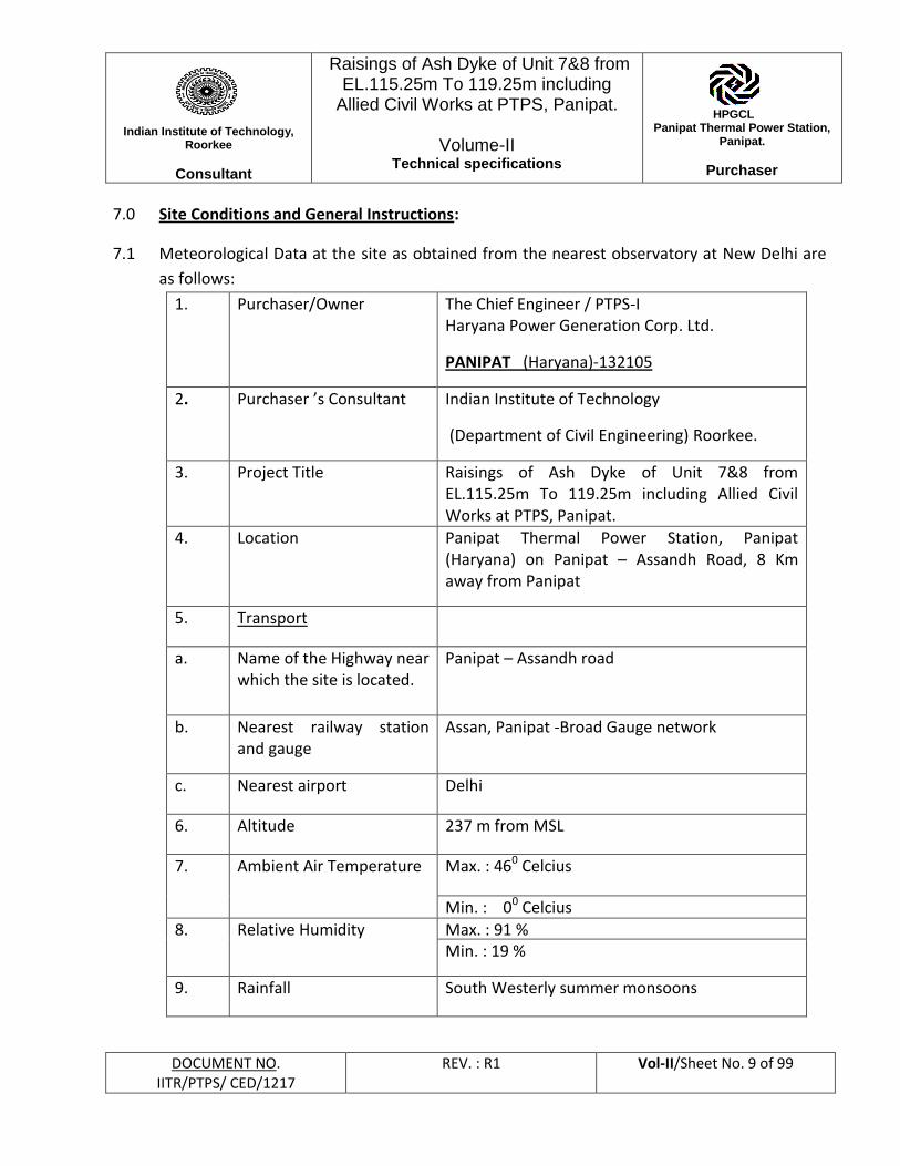
7.1 Meteorological Data at the site as obtained from the nearest observatory at New Delhi are
as follows:
1. Purchaser/Owner The Chief Engineer / PTPS-I Haryana Power Generation Corp. Ltd.
PANIPAT (Haryana)-132105
2. Purchaser ’s Consultant Indian Institute of Technology
(Department of Civil Engineering) Roorkee.
3. Project Title Raisings of Ash Dyke of Unit 7&8 from EL.115.25m To 119.25m including Allied Civil Works at PTPS, Panipat.
4.
Location Panipat Thermal Power Station, Panipat (Haryana) on Panipat – Assandh Road, 8 Km away from Panipat
5. Transport
a. Name of the Highway near which the site is located.
Panipat – Assandh road
b. Nearest railway station and gauge
Assan, Panipat -Broad Gauge network
c. Nearest airport Delhi
6. Altitude 237 m from MSL
7. Ambient Air Temperature Max. : 460 Celcius
Min. : 00 Celcius
8. Relative Humidity Max. : 91 % Min. : 19 %
9. Rainfall South Westerly summer monsoons
Indian Institute of Technology,
Roorkee
Consultant
Raisings of Ash Dyke of Unit 7&8 from EL.115.25m To 119.25m including
Allied Civil Works at PTPS, Panipat.
Volume-II Technical specifications
HPGCL Panipat Thermal Power Station,
Panipat.
Purchaser
DOCUMENT NO. IITR/PTPS/ CED/1217
REV. : R1 Vol-II/Sheet No. 10 of 99
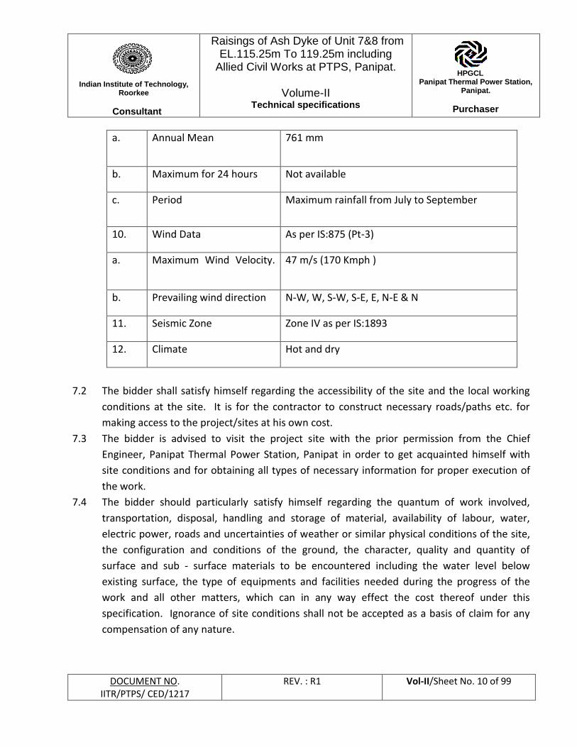
a. Annual Mean 761 mm
b. Maximum for 24 hours Not available
c. Period Maximum rainfall from July to September
10. Wind Data As per IS:875 (Pt-3)
a. Maximum Wind Velocity.
47 m/s (170 Kmph )
b. Prevailing wind direction N-W, W, S-W, S-E, E, N-E & N
11. Seismic Zone Zone IV as per IS:1893
12. Climate Hot and dry
7.2 The bidder shall satisfy himself regarding the accessibility of the site and the local working
conditions at the site. It is for the contractor to construct necessary roads/paths etc. for
making access to the project/sites at his own cost.
7.3 The bidder is advised to visit the project site with the prior permission from the Chief
Engineer, Panipat Thermal Power Station, Panipat in order to get acquainted himself with
site conditions and for obtaining all types of necessary information for proper execution of
the work.
7.4 The bidder should particularly satisfy himself regarding the quantum of work involved,
transportation, disposal, handling and storage of material, availability of labour, water,
electric power, roads and uncertainties of weather or similar physical conditions of the site,
the configuration and conditions of the ground, the character, quality and quantity of
surface and sub - surface materials to be encountered including the water level below
existing surface, the type of equipments and facilities needed during the progress of the
work and all other matters, which can in any way effect the cost thereof under this
specification. Ignorance of site conditions shall not be accepted as a basis of claim for any
compensation of any nature.

Indian Institute of Technology,
Roorkee
Consultant
Raisings of Ash Dyke of Unit 7&8 from EL.115.25m To 119.25m including
Allied Civil Works at PTPS, Panipat.
Volume-II Technical specifications
HPGCL Panipat Thermal Power Station,
Panipat.
Purchaser
DOCUMENT NO. IITR/PTPS/ CED/1217
REV. : R1 Vol-II/Sheet No. 11 of 99
7.5 The contractor shall make his own arrangements for construction and potable water. He
shall also ensure that only the good quality of water as per the requirement of the
specifications is used.
7.6 During the course of contractor's work, other works may also be in progress at site. The
contractor is to use his best efforts to work in harmony with others and in the best over all
interest of the project.
7.7 The information given to the bidders in technical specification comprising of all sections is
meant to serve as a guide, it is, therefore imperative that the bidder shall obtain and
examine himself all the data, information and particulars required for the satisfactory
execution of the work under this specification, however no claim on account of any
deviation in the acual data being at variance with that furnished in the bid shall be
entertained
7.8 All material supplied by the contractor shall be best quality and shall conform to relevant
Indian Standard Codes of Practice, this specification and construction drawings. Approval in
writing from the Engineer - in - Charge shall be obtained by the contractor before any
alternative or equivalent material is used other than that specified in the construction
drawings/specification.
7.9 During inclement weather contractor shall suspend concreting, plastering, laying of ash,
impervious layer, sand layer etc. for such time as the Engineer - in - Charge may direct and
shall protect all works from damage during the construction. No claim whatsoever on this
account shall be entertained.
7.10 If the work is suspended by reason of rain, strike lockout or any other cause, the contractor
shall take the precautions necessary for the protection of wok and at his own expense shall
make good any damage arising from any of these causes.
7.11 Deviation limit for the quantum of works as a whole shall be + 10% of the total quantum of
work as per contract. The quantity for individual items can vary to any extent.
7.12 Guarantee Period: The period of guarantee for work covered in this specification shall be
one year after the completion of the work as a whole and its acceptance by the
Engineer - in - Charge.
7.13 The bidder is expected to get clarified any doubts about the specification, site conditions
and other tender documents etc. before bidding by discussion and the same shall be
recorded in writing with the Purchaser in respect of the interpretation of any portion of
the document.
Indian Institute of Technology,
Roorkee
Consultant
Raisings of Ash Dyke of Unit 7&8 from EL.115.25m To 119.25m including
Allied Civil Works at PTPS, Panipat.
Volume-II Technical specifications
HPGCL Panipat Thermal Power Station,
Panipat.
Purchaser
DOCUMENT NO. IITR/PTPS/ CED/1217
REV. : R1 Vol-II/Sheet No. 12 of 99
7.14 The contractor shall bear the payments required for any of the Royalty/or cost of land/or
rent/or any other charge for the borrow area materials and nothing extra shall be payable
7.15 Testing Laboratory: The contractor shall establish testing laboratory required for the
purpose of carrying out tests regularly during the period of construction and nothing extra
shall be payable to the contractor for establishing the laboratory.
7.16 Escalation: The rates quoted shall be firm and no escalation in the rates and costs shall be
allowed except otherwise specified in General Terms and Conditions. No extra payment
shall be allowed for extra shifts or night shifts etc.
8.0 Purchaser's Scope of Supply
8.1 The Engineer - in - Charge shall hand over site to the contractor within 7 days of the date of
issue of letter accepting the tender for enabling the contractor to make arrangements for his
store sheds, cements sheds, temporary office etc.
8.2 All materials including Cement and reinforcement steel required for the work shall be
arranged by the contractor.
9.0 Layout and Levels
9.1 The layout and levels of the ash dyke shall be made by the contractor at his own cost from
reference point and the benchmark given to him at site by the Engineer - in - Charge. The
contractor shall provide necessary help in instruments materials and men to the Engineer -
in - Charge for checking the correctness of detailed layout and levels. However, checking by
the Engineer - in - Charge shall not relieve the contractor of his responsibility for correct
execution of works as per construction drawing and he shall be solely responsible for
correctness of layout and levels.
9.2 Surveying
9.2.1 As soon as the contract is awarded, the Contractor shall mobilize necessary instruments and
personnel to arrange for accurate surveying of the area where the bunds are to be located in
the presence of the Engineer-in-Charge or his authorized representative. Levels shall be
obtained at every 10m intervals along the length of the bund and at every 5m intervals along
the width of the bund and shall cover the complete plan area likely to be occupied by the
bund. The Contractor shall plot all these levels and prepare longitudinal section at center line
of the proposed bund and cross sections at every 10m interval and shall submit four sets of
the same to the Purchaser.
Indian Institute of Technology,
Roorkee
Consultant
Raisings of Ash Dyke of Unit 7&8 from EL.115.25m To 119.25m including
Allied Civil Works at PTPS, Panipat.
Volume-II Technical specifications
HPGCL Panipat Thermal Power Station,
Panipat.
Purchaser
DOCUMENT NO. IITR/PTPS/ CED/1217
REV. : R1 Vol-II/Sheet No. 13 of 99
9.2.2 The survey shall be repeated after excavation & preparation of foundation for ash bund is
completed as per clause 9.2.1. Four copies each of the longitudinal section and cross
sections shall again be submitted to the Purchaser.
9.2.3 Cross sections and longitudinal section as approved by Purchaser shall from the basis for
calculation of the quantities for the bund for payment purposes.
10.0 Diversion of ash slurry water from construction area and drainage of storm water from
catchments of bunds during execution
10.1 Construction of Diversion Bund for diversion of flow of ash slurry
The construction of work shall be planned in such a way that ash slurry/water in ash pond
remains at safe distance away from construction area. Ash slurry in ash pond is continuously
being discharged from FTPS and clear water after settlement of ash is taken out through 2
nos. decantation wells provided for disposal of decanted water. Construction area shall be
kept dry by providing protection bund of adequate size with locally available pond ash and
soil (to be brought from outside at his own cost) at safe distance away from the construction
area and dewatering, if required. The work shall be proceeded in such a manner that one no.
decantation well is always available for disposing the decanted water from ash pond. After
completion of the entire construction activities, the temporary protection bund shall be
dismantled.
10.2 The catchment area of the pond itself might yield large quantities of water during heavy
rains. This water has to be properly drained off during the execution to facilitate
uninterrupted construction activities. The contractor shall estimate the run-off from
meteorological data as specified above and shall design a scheme for interception and
disposal of this water and submit the same for the approval of the purchaser. After the
scheme has been approved by the purchaser, this temporary, work shall be undertaken by
the contractor at his own cost. However, such approval by purchaser does not absolve the
contractor from his responsibility for the adequacy of the design of the drainage system. This
temporary drainage system shall be dismantled after the bund construction is completed in
all other respects. Sluices or other openings left in the body of the bund shall be plugged
with concrete of grade 1:2:4 and grouted to the complete satisfaction of the purchaser.
Indian Institute of Technology,
Roorkee
Consultant
Raisings of Ash Dyke of Unit 7&8 from EL.115.25m To 119.25m including
Allied Civil Works at PTPS, Panipat.
Volume-II Technical specifications
HPGCL Panipat Thermal Power Station,
Panipat.
Purchaser
DOCUMENT NO. IITR/PTPS/ CED/1217
REV. : R1 Vol-II/Sheet No. 14 of 99
10.3 Dewatering if required during the execution of the entire activities shall be in the scope of
the contractor and nothing extra on this account shall be paid. The contractor is advised to
visit the site of work before submitting the tender to acquaint himself regarding the site
conditions.
10.4 The work to be performed under the specification consists of providing all labour,
supervision, materials, scaffolding, power, fuel, construction equipment, tools and plant etc.
Indian Institute of Technology,
Roorkee
Consultant
Raisings of Ash Dyke of Unit 7&8 from EL.115.25m To 119.25m including
Allied Civil Works at PTPS, Panipat.
Volume-II Technical specifications
HPGCL Panipat Thermal Power Station,
Panipat.
Purchaser
DOCUMENT NO. IITR/PTPS/ CED/1217
REV. : R1 Vol-II/Sheet No. 15 of 99
11.0 Excavation :
11.1 Excavation in Soil
11.1.1 The specifications for excavation in soil shall apply to excavation work in rock also, except for
the bottom of excavation, where depending on the type of rock, over-breaks up to a
maximum depth of 0.3m below the required level may be allowed by the Engineer-in-Charge
at his discretion and paid accordingly.
11.1.2 Sides and bottoms of excavation shall be cut sharp and true to line and level. Undercutting
shall not be permitted. When machines are used for excavation, the last 300 mm before
reaching the required level shall be excavated manually or by such equipment so that soil at
the required final level shall be left in its natural condition. Suitability of strata (at the
bottom of excavations) for laying the foundation thereon shall be determined by the
Engineer - in - Charge.
11.1.3 Excavation for foundation shall be to the bottom level of lean concrete or as shown in
construction drawings and as directed by the Engineer - in - Charge. The bottom level of all
excavations shall be trimmed to required levels and when excavation is carried below such
levels, by error, it shall be brought back to specified level by filling with concrete of nominal
mix 1: 3:6 (cement : fine aggregate : coarse aggregate) as directed by the Engineer - in –
Charge at his own cost.
11.1.4 The Contractor shall ascertain for himself the nature of materials to be excavated and the
difficulties, if any, likely to be encountered in executing this work. Coffer dams, sheeting,
shoring, bracing maintaining suitable slopes, draining etc. shall be provided and installed by
the Contractor, to the satisfaction of the Engineer - in - Charge.
11.1.5 All excavation for installation of underground facilities, such as piping, sewer lines, drain
lines etc. shall be open cuts. For deep and huge excavations and in other excavations, if
required by the Engineer - in - Charge, the Contractor shall submit for approval an
"Excavation Scheme” showing the methodology to be adopted for excavation in order to
maintain the stability of side slopes, means for ensuring safety of existing facilities nearby,
dewatering etc. However, the Contractor shall be fully responsible for the scheme
irrespective of any approvals granted. Benching shall be provided for deeper excavation
whenever required.
11.1.6 When excavation requires bracing, sheeting or shoring etc., the Contractor shall submit to
design and drawings to the Engineer - in - Charge, showing arrangements, details of
proposed installation and structural safety. The Contractor shall also furnish all supporting
Indian Institute of Technology,
Roorkee
Consultant
Raisings of Ash Dyke of Unit 7&8 from EL.115.25m To 119.25m including
Allied Civil Works at PTPS, Panipat.
Volume-II Technical specifications
HPGCL Panipat Thermal Power Station,
Panipat.
Purchaser
DOCUMENT NO. IITR/PTPS/ CED/1217
REV. : R1 Vol-II/Sheet No. 16 of 99
design calculations as called for and shall not proceed until he has received written approval
from the Engineer-in-Charge. However, the responsibility for adequacy of such bracing,
sheeting, shorting etc., shall rest with the contractor, irrespective of any approval of the
Engineer-in-Charge.
11.1.7 The Contractor shall have to constantly pump out any water collected in excavated pits and
other areas due to seepage, rain water, springs etc., and maintain dry working conditions at
all times until the excavation, placement of lean concrete, reinforcement, shuttering,
concreting, backfilling is completed. The Contractor shall remove all sludge / muck from the
excavated areas to keep the work area dry. The Contractor, if required, shall employ sludge
pumps, for this purpose.
11.1.8 The Contractor shall have to remove all materials arising from excavations from the vicinity
of the work either for direct filling, stacking and subsequent filling or for ultimate disposal as
directed by the Engineer-in-Charge. In no case, the excavated soil shall be stacked within a
distance of 1.5m from the edge of excavation or one-third the depth of excavation
whichever is more. Material to be used for filling shall be kept separately.
11.1.9 For purpose of excavation of earthwork, the term soil shall apply to all kind of soil containing
any percentage of kankar, moorum or/and shingle etc.
11.1.10 Disposal of Surplus Earth
The Contractor shall arrange to transport the surplus excavated soil remaining after
backfilling to the area within a total lead of 500m including all lifts etc. as directed by the
Engineer-in-Charge. The soil so transported shall be stacked and levelled neatly. The unit
rate for excavation shall include loading, transporting, unloading and stacking, levelling
complete. The disposal area shall be intimated by the Engineer-in-Charge.
11.1.11Measurement and Payment
(a) All excavation shall be measured net in cubic meter. Dimension for the purpose of
payment shall be reckoned on the horizontal area of the excavation at the base for
foundation of the walls, columns, footings, tanks, rafts, or other foundations/structures
to be built, multiplied by the mean depth from the surface of the ground in accordance
with the drawings. Excavation for side slope wherever provided for safety of excavation
shall not be paid. The contractor shall make such allowance in his rates to provide for
excavation in side slopes keeping in mind the nature of the soil and safety of excavation.
If pay line of adjacent foundations overlap, the over-lapped portion shall be paid only
once. The length, width and depth of excavation shall be measured in meter correct up
Indian Institute of Technology,
Roorkee
Consultant
Raisings of Ash Dyke of Unit 7&8 from EL.115.25m To 119.25m including
Allied Civil Works at PTPS, Panipat.
Volume-II Technical specifications
HPGCL Panipat Thermal Power Station,
Panipat.
Purchaser
DOCUMENT NO. IITR/PTPS/ CED/1217
REV. : R1 Vol-II/Sheet No. 17 of 99
to second place of decimal. The volume of excavation calculated in cum. shall be
rounded of to the second place of decimal. Nothing extra shall be payable for slope,
shoring, strutting, dewatering etc. irrespective of whatever is provided.
12 Filling, Back Filling and Site Grading:
12.1 General:
All fill material will be subject to the Engineer’s approval. If the Engineer rejects any material,
the Contractor shall remove the same forth with from the site at no extra cost to the Owner.
Surplus fill material shall be deposited/ disposed off as directed by the Engineer after the fill
work is completed. No earth fill shall commence until surface water discharges and streams
have been properly intercepted or otherwise dealt with as directed by the Engineer.
12.2 Material:
To the extent available, selected surplus soils from excavated materials shall be used as
backfill. Fill material shall be free from clods, salts, sulphates, and organic or other foreign
material. All clods of earth shall be broken or removed. Where excavated material is mostly
rock, the boulders shall be broken into pieces not larger than 150mm size, mixed with
properly graded fine material consisting of minimum or earth to fill up the voids and the
mixture used for filling.
If any selected fill material is required to be borrowed, the Contractor shall make
arrangements, for bringing such material from outside borrow pits. The material and source
shall be subject to prior approval of the Engineer. The approved borrow pit area shall be
cleared of all bushes, roots of trees, plants rubbish etc. top soil containing salts/ sulphate
and other foreign material shall be removed. The materials so removed shall be burnt or
disposed off as directed by the Engineer. The Contractor shall make necessary access roads
to borrow areas and maintain the same, if such access road does not exist, at his cost.
12.3 Filling in pits and trenches around foundations of structures, walls etc.
As soon as the work in foundations has been accepted and measured, the spaces around the
foundations, structures, pits, trenches etc, shall be cleared of all debris, and filled with earth
in layers not exceeding 15cm., each layer being watered, rammed and properly
consolidated, before the succeeding one is laid. Each layer shall be consolidated to the
Indian Institute of Technology,
Roorkee
Consultant
Raisings of Ash Dyke of Unit 7&8 from EL.115.25m To 119.25m including
Allied Civil Works at PTPS, Panipat.
Volume-II Technical specifications
HPGCL Panipat Thermal Power Station,
Panipat.
Purchaser
DOCUMENT NO. IITR/PTPS/ CED/1217
REV. : R1 Vol-II/Sheet No. 18 of 99
satisfaction of the Engineer. Earth shall be rammed with approved mechanical compaction
machines. Usually no manual compaction shall be allowed unless the Engineer is satisfied
that in some cases manual compaction by tampers cannot be avoided. The final backfill
surface shall be trimmed and leveled to proper profile as directed by the Engineer or
indicated on the drawings.
12.4 Filling in trenches
Filling in trenches for pipes and drains shall be commended as soon as the joints of pipes and
drains have been tested and passed. The backfilling material shall be properly consolidated
by watering and ramming, taking due care that no damage is caused to the pipes.
Where the trenches are excavated in soil, the filling from the bottom of the trench to the
level of the centerline of the pipe shall be done by hand compaction with selected approved
earth in layers not exceeding 8 cm; backfilling above the level of the centerline of the pipe
shall be done with selected earth by hand compaction or other approved means in layers not
exceeding 15 cm.
In case of excavation of trenches in rock, the filling up to a level 30-cm, above the top of the
pipe shall be done with fine materials, such as earth, moorum etc. The filling up of the level
of the centerline of the pipe shall be done by hand compaction in layers not exceeding 8 cm.
whereas the filling above the centerline of the pipe shall be done by hand compaction or
approved means in layers not exceeding 15cm. The filling from a level 30 cm. above the top
of the pipe to the top of the trench shall be done by hand or other approved mechanical
methods with broken rock filling of size not exceeding 15cm mixed with fine material as
available to fill up voids.
Filling of the trenches shall be carried simultaneously on both sides of the pipe to avoid
unequal pressure on the pipe.
12.5 Measurement and Payments
12.5.1 Backfilling on the sides of foundations of columns, footings, structures, walls, tanks, rafts
trenches etc. with available excavated material shall be paid for separately. Measurement
for payment shall be based on volume calculations. The length, width and depth of backfill
shall be measured in meter correct upto second place of decimal. The volume of backfilling
calculated in cu.m. shall be rounded of to the second place of decimal.
Indian Institute of Technology,
Roorkee
Consultant
Raisings of Ash Dyke of Unit 7&8 from EL.115.25m To 119.25m including
Allied Civil Works at PTPS, Panipat.
Volume-II Technical specifications
HPGCL Panipat Thermal Power Station,
Panipat.
Purchaser
DOCUMENT NO. IITR/PTPS/ CED/1217
REV. : R1 Vol-II/Sheet No. 19 of 99
12.5.2 Backfilling to be done with borrowed earth, wherever shown in the drawing shall be paid as
per the actual compacted volume subject to maximum as shown in the drawing which will
include preparation of borrow area, excavation, loading, transportation, unloading, laying in
layers, compacting, royalty/taxes etc. complete as per specification
13.0 Ash Fill Material for Zone – II:
13.1 Borrow Area:
The borrow areas for excavation of the ash fill material required to raise the ash dyke shall
be away from the proposed site of the ash dyke by minimum of 25M. The borrow areas shall
be cleared of all the bushes and any rubbish before actual excavation and placement. All the
borrow areas from where ash is to be removed should be cut into a maximum slope of 1: 2.5
(1 Vertical: 2.5 Horizontal).
13.2 Preparation of Borrow Areas:
All areas required for borrowing pond ash for the construction of ash dyke shall be cleared of
all trees and roots, bushes, rubbish and other objectionable materials. Particular care shall
be taken to exclude all organic matter to be placed in the ash dyke. The cleared areas shall
be maintained free of vegetation growth during progress of the work.
13.3 Stripping of Borrow Areas:
Borrow area shall be stripped of 0.50 M (Minimum) top layer of pond ash and any other
matter which is unsuitable for the purpose for which the borrow area is to be excavated.
The stripping operation shall be limited only to designated borrow areas and dumping of
stripping materials shall be done as per the direction of the Engineer - in - Charge.
13.4 Geo - Technical Properties of the Pond Ash in Zone - II:
13.4.1 The material for placement in Zone - II shall be tested to obtain following geo - technical
properties as per IS 2720.
(i) Grain size distribution analysis and curve;
(ii) Index properties;
(iii) Shear strength parameters;
(iv) Optimum moisture content at SPD;
Indian Institute of Technology,
Roorkee
Consultant
Raisings of Ash Dyke of Unit 7&8 from EL.115.25m To 119.25m including
Allied Civil Works at PTPS, Panipat.
Volume-II Technical specifications
HPGCL Panipat Thermal Power Station,
Panipat.
Purchaser
DOCUMENT NO. IITR/PTPS/ CED/1217
REV. : R1 Vol-II/Sheet No. 20 of 99
(v) Maximum Standard Proctor dry density;
(vi) Permeability at 95% SPD;
(vii) Consolidation parameters.
13.4.1 The tentative values of various properties of pond ash based on available record with project
authorities as considered at tender level design are given in Annexure - II.
14.0 Impervious Materials for Zone – I:
14.1 Borrow Areas:
All the material required for the construction of impervious soil cover in zone - I of ash dyke
should be arranged by the contractor. The borrow area and the soil to be obtained there
from shall be got approved from Engineer - in - Charge before placing the selected
impervious soil in Zone - I of the ash dyke. The soil used for soil cover shall be free from
admixtures of stiff clay, stumps, roots, rock, weeds and other material, which would be
detrimental to the proper development of the vegetative growth. The soil should have
following grading.
Sand - 20% to 75%
Silt- 10% to 60%
Clay- 5% to 30%
The co - efficient of permeability of the impervious soil shall not be more than 5 x 10⁻⁶
cm/sec. (5 lugeons).
14.2 Preparation of Borrow Areas:
All areas required for borrowing earth for ash dyke shall be cleared of all trees and roots,
bushes rubbish and other objectionable materials. Particular care shall be taken to exclude
all organic matter to be placed in the ash dyke. The cleared areas shall be maintained free of
vegetation growth during progress of the work.
14.3 Stripping of Borrow Areas:
Borrow area shall be stripped of topsoil and any other matter which is unsuitable for the
purpose for which the borrow area is to be excavated. The stripping operation shall be
Indian Institute of Technology,
Roorkee
Consultant
Raisings of Ash Dyke of Unit 7&8 from EL.115.25m To 119.25m including
Allied Civil Works at PTPS, Panipat.
Volume-II Technical specifications
HPGCL Panipat Thermal Power Station,
Panipat.
Purchaser
DOCUMENT NO. IITR/PTPS/ CED/1217
REV. : R1 Vol-II/Sheet No. 21 of 99
limited only to designated borrow areas and dumping of stripping materials shall be done as
per the direction of the Engineer - in - Charge.
14.4 Geo - Technical Properties of the Impervious Material in Zone - I:
The material for placement in Zone - I shall be tested so as to conform to the properties as
mentioned in clause 14.1
15.0 Sand for Filter Material in Zone – III:
15.1 Sand to be used shall be clean, sound and durable and should be free from silt and other
impurities. The gradation of sand shall confirm to clause 16.10 of this specification.
16.0 Construction of Ash Dyke:
16.1 Surface Treatment of Pond Ash: The top surface of ash in the pond is at about EL + 115.25m
in general near starter dyke and within the base strip of proposed ash dyke. But due to
uneven filling, the top level of ash may be more or less than EL + 115.25 M in some places
near starter dyke and within the base strip of proposed dyke. The base area for ash dyke
construction shall be treated to ensure satisfactory foundation beneath ash fill by removing
all vegetation and 0.50 M top layer of settled ash within the base strip of the proposed dyke
to ensure satisfactory foundation of ash dyke. In areas where after the removal of 0.5 M of
ash, the level is higher than EL + 114.75 M, in such areas, ash shall be further removed to
achieve the level of EL 114.75M. However, in areas where the level after removal of 0.5 M
of ash is below EL 114.75 M such areas shall be filled up with ash to be obtained from
borrow areas to achieve the level of EL 114.75M and this ash shall be compacted in a similar
fashion as specified for the construction of ash dyke. The payment of the same shall be
made under item at Sr. no.3 of Price schedule.
The vegetation and excavated top settled ash should not be used for construction purpose.
The exposed ash material in the base strip shall be tested by the contractor as specified in
CI.16.13.4. If the excavated surface thus exposed is having higher moisture content than the
Optimum Moisture Content (OMC) shall have to be left exposed to dry up to attain OMC,
and after attainment of OMC or otherwise if the water content of the exposed ash is not
higher than OMC shall immediately be compacted with compaction equipment to achieve
95% compaction of maximum standard proctor dry density. The test for compacted ash in
the base strip shall be carried out as per CI.16.13.4
Indian Institute of Technology,
Roorkee
Consultant
Raisings of Ash Dyke of Unit 7&8 from EL.115.25m To 119.25m including
Allied Civil Works at PTPS, Panipat.
Volume-II Technical specifications
HPGCL Panipat Thermal Power Station,
Panipat.
Purchaser
DOCUMENT NO. IITR/PTPS/ CED/1217
REV. : R1 Vol-II/Sheet No. 22 of 99
16.2 Spreading and Compaction:
The ash dyke shall be constructed from the ash excavated from the ash pond and stilling
ponds. The ash is stockpiled in the dyke area and the same is spread horizontally with
dozers in layers of 20 cm thickness. The spreading shall be done on the entire width of the
dyke. After spreading, ash shall be compacted with 8/10 tones vibratory roller or any other
suitable means to achieve a minimum field density of 95% of maximum proctor dry density
obtained in the field laboratory. The test for ascertaining the geo - technical properties of
the ash shall be carried out as per CI.16.13.4.
16.3 Benching:
On the areas where as embankment is to be constructed adjacent to the natural soil, the
slope should be benched with approximately 200 mm interval to ensure that new ash
embankment is properly tied into the existing slopes.
16.4 Soil Cover (Impervious Zone):
The major risks associated with compacted ash dyke are erosion of the ash both internally
and externally and liquefaction. Ash dyke shall be covered with non - erodible soil cover
(impervious soil cover) of 0.5M thicknesses and compacted to maintain required dry density
of 95% of maximum standard proctor dry density. The permeability of the selected
impervious soil (Zone-I) shall not be more than of 5 x 10⁻⁶ cm/sec. The tests for ascertaining
the geo - technical properties of soil in Zone - I shall be carried out as per C1.14.4
16.5 Compaction Equipment
The compaction shall be carried out using pneumatic rollers or vibratory rollers for
compacting ash/ cohesion less materials and sheep foot rollers or pneumatic rollers for
compacting cohesive materials. Rolling shall be commenced from outer edge and progress
towards centre. The engineer based on the results of the test section shall as finally approve
the number of passes. However, in no case the number of passes shall be less than 8.
16.5.1 Pneumatic Rollers
Pneumatic rollers shall have four wheels equipped with pneumatic tyres, and a body
suitable for ballast loading so that the load per wheel may be varied as necessary from 7 to
11 tonnes. Tyre pressure shall not exceed 2.5 Kg/cm², as greater pressure tends to cut ash
Indian Institute of Technology,
Roorkee
Consultant
Raisings of Ash Dyke of Unit 7&8 from EL.115.25m To 119.25m including
Allied Civil Works at PTPS, Panipat.
Volume-II Technical specifications
HPGCL Panipat Thermal Power Station,
Panipat.
Purchaser
DOCUMENT NO. IITR/PTPS/ CED/1217
REV. : R1 Vol-II/Sheet No. 23 of 99
surface. The tyres shall be of such size and ply as can be maintained during rolling
operations, a tyre pressure not greater than 1.5 Kg/cm² for a 11 tonnes wheel load. The
roller wheels shall be located abreast and each wheel and tyre shall be mounted in such a
way that all wheels exert approximately equal loads, when traversing uneven grounds.
16.5.2 Vibratory Rollers
Vibratory rollers shall have dead weight 7 to 15 tonnes and the vibrators shall have
frequency between 1100 and 1800 pulses minute and amplitude of vibration shall be
between 0.5mm and 1.5mm.
16.5.3 Sheep Foot Rollers
Each drum of a roller shall have an outside diameter of not less than 1.5m and shall not be
more than 1.8m in length. The space between two adjacent drums when on level surface
shall neither be less than 30 cm nor more than 40 cm. Each drum shall be free to pivot
about an axis parallel to the direction of travel.
At least one tamping foot shall be provided for each 600 cm² of drum surface. The shape
measured on the surface of the drum, between the centers of any two adjacent tamping
feet, shall not be less than 25 cm. The length of each tamping foot from the outside surface
of the drum shall be maintained at not less than 25cm. The cross sectional area of each
tamping foot shall not be more than 60 cm² at a plane normal to the axis of the shank 15cm
from the drum surface, and shall be maintained at not less than 45 cm² and not more than
60cm² at a plane normal to the axis of the shank 20 cm from the drum surface.
The weight of a roller when fully loaded shall not be less than 7 tonnes per drum. The
loading used in the roller drums and operating of rollers shall be as required to obtain the
desired breakdown and compaction of materials. If more than one roller is used on any one
layer of fill, all rollers so used shall be of the same type and essentially of the same
dimensions. Tractors used for pulling rollers shall have sufficient power to pull them at a
speed of about 4 Km/hour with drums fully loaded. During the operation of rolling, the
spaces between the tamping feet shall be kept clear of materials, which could impair the
effectiveness of the tamping rollers. If the rollers used are at tandem, the tamper spacing
shall be set so that the circumferential rows of the rear drums are in line with the mid-point
between the circumferential rows on the forward drums.
Indian Institute of Technology,
Roorkee
Consultant
Raisings of Ash Dyke of Unit 7&8 from EL.115.25m To 119.25m including
Allied Civil Works at PTPS, Panipat.
Volume-II Technical specifications
HPGCL Panipat Thermal Power Station,
Panipat.
Purchaser
DOCUMENT NO. IITR/PTPS/ CED/1217
REV. : R1 Vol-II/Sheet No. 24 of 99
16.6 Dressing and Trimming of the Slopes
16.6.1 The outer slopes of the embankment shall be neatly dressed to line as the placing of the fill
progresses. Compaction shall extend over the full width of the embankment and the
material in the slopes shall be compacted as for the rest of structure. To ensure proper
compaction at the outer edge, the fill shall be constructed for a minimum of 500 mm extra
width on edges and the outer edge dressed to true width and slope after compaction. No
soil cover slope shall be left without trimming to design slope. Slopes shall be maintained
until final completion and acceptance. Any material that is lost by weathering or due to any
other cause shall be replaced and make good at his own cost. The trimmed materials are
permitted for reuse in the embankment. No separate payment will, however, be made for
forming extra width offsets or trimming the slopes and the unit rates for the embankment
work shall, therefore, provide for the same.
16.6.2 The soil cover shall be constructed either simultaneously with the ash fill or separately after
the ash fill is compacted in layers of specified thickness. If laid separately the trimmed slopes
of the bund should be scarified and 200mm deep keys should be provided at spacing not
exceeding 3meter center-to-center both across and along the slope with dragline bucket or
other suitable method and nothing extra shall be paid on this account. The soil layer shall be
placed in thickness not more than 200mm and properly compacted using suitable
compactors.
16.6.3 In those parts of the ash bund which are inaccessible to the specified rolling equipment, e.g.
around and in contact with structures, and in proximity to structures where the rolling
equipment will not be permitted to operate, compaction shall be accomplished by
mechanical tampers of approved type. Rollers will not be permitted to operate within three
meter of concrete structures, and all fill within this distance shall be spread in layers not over
75 mm thick when loose. The moisture content of the material and the amount of tamping
shall be such as to produce a degree of compaction equal to that specified for rolled fill.
16.7 Construction Joints
A construction joint shall mean a compacted fill surface made to a slope exceeding the
slope of bonding surface but not exceeding 1 vertical to 3 horizontal. A bonding surface
shall mean a compacted fill surface made to a slope not exceeding 1 vertical to 8 horizontal.
Indian Institute of Technology,
Roorkee
Consultant
Raisings of Ash Dyke of Unit 7&8 from EL.115.25m To 119.25m including
Allied Civil Works at PTPS, Panipat.
Volume-II Technical specifications
HPGCL Panipat Thermal Power Station,
Panipat.
Purchaser
DOCUMENT NO. IITR/PTPS/ CED/1217
REV. : R1 Vol-II/Sheet No. 25 of 99
Prior to placing a layer of fill material against previously placed fill at any construction joint,
the surface materials at the joint shall be cut back horizontally to a distance sufficient to
accommodate a layer of the fill material to be placed; but in any event to a horizontal
distance one meter in excess of that required to expose a dense face of the previously
placed and compacted fill and in height equal to the thickness of the layer to be placed.
All loosened and dried ash/soil from the surface of the construction joint shall be removed
or reconditioned for use. Prior to placing each layer on the freshly exposed surface, such
surface shall be scarified if necessary. The freshly placed fill at construction joints shall be
placed and compacted as specified except that the rolling pattern of the compaction
equipment shall be so adjusted in the region of the joints that compaction shall be carried
over the edge of the newly placed fill into the previously placed fill by a minimum of one
meter measured horizontally.
No cutting back and tying will be required at bonding surfaces, but all loose material shall
be removed from such surfaces, before placing the subsequent layer.
16.8 Internal Drainage System:
For efficient functioning of the raised embankment, the internal drainage system should
operate and continue to operate efficiently. The internal drain consisting of Gabion wall/
rock , geo-textile, 0.50 m thick sand blanket and sand chimney filter shall be provided to
control seepage discharge from internal surface. The seepage discharge from internal
surfaces must be controlled with filters that permit water to escape freely and also hold
particles in places and the piezo - metric surface on the downstream of the dyke.
16.9 Sand Blanket and Sand Chimney:
Sand filters of the dimensions specified in drawings shall be provided on the location shown
in the drawings. The thickness of sand blanket and sand chimney shall be minimum 0.50 M.
Sand filter shall be laid in 20 cm layers and shall be compacted by 8 tones/10 tones vibratory
Roller or other approved equipment. Well-graded sand for filter shall be compacted to a
minimum relative density of 70% as determined by the standard U.S. Bureau of Reclamation
relative density tests for cohesion less free - draining solids.
Indian Institute of Technology,
Roorkee
Consultant
Raisings of Ash Dyke of Unit 7&8 from EL.115.25m To 119.25m including
Allied Civil Works at PTPS, Panipat.
Volume-II Technical specifications
HPGCL Panipat Thermal Power Station,
Panipat.
Purchaser
DOCUMENT NO. IITR/PTPS/ CED/1217
REV. : R1 Vol-II/Sheet No. 26 of 99
16.10 Gradation of Filter Layer and Grain Size Curve:
16.10.1 Scope This section of the specification covers supplying and forming of sand blanket on the foundation of embankment, sand chimney in the bund and sand filters between rock-toe and foundation and along the slope as indicated in the drawings.
16.10.2 General Requirements The Contractor shall furnish all labour and materials required for the complete performance of the work in accordance with the drawings, schedule of item and as described herein.
16.10.3 Sand Blanket
As indicated in the drawing graded sand blanket shall be laid on the foundation. The thickness of graded sand blanket layer shall be as specified or as directed by the Engineer.
16.10.4 Sand Chimney
As indicated in the drawing sand chimney of specified thickness shall be laid as shown in the drawing.
16.10.5 Sand Filter
Graded sand filter of specified thickness shall be laid as indicated in the drawing along the slope of the bund and underneath the rock-toe.
16.10.6 Material
The material for blanket, chimney and sand filters shall consist of clean, sound and well graded coarse sand. The materials shall be free from debris wood, vegetable matter and other deleterious matter. The gradation of sand material shall meet the requirements as specified below: a) D 50 of filter --------------------- < 25 D 50 of base material b) D 50 of filter --------------------- = 6 to 19 D 50 of base material
Indian Institute of Technology,
Roorkee
Consultant
Raisings of Ash Dyke of Unit 7&8 from EL.115.25m To 119.25m including
Allied Civil Works at PTPS, Panipat.
Volume-II Technical specifications
HPGCL Panipat Thermal Power Station,
Panipat.
Purchaser
DOCUMENT NO. IITR/PTPS/ CED/1217
REV. : R1 Vol-II/Sheet No. 27 of 99
(c) D 85 of filter --------------------- > 5 D 15 of filter d) D 15 of filter --------------------- < 5 D 85 of base material e) The gradation curve of the filter material shall be nearly parallel to the
gradation curve of the base material. f) The filters shall not contain more than 5% by weight of materials finer than
0.075 mm size. g) The sand filter layer shall be considered as the base material for coarser filter
layer. h) The filter material shall be suitably compacted to a firm condition to achieve a
relative density of 70%. i) In addition to the above, the provisions for filter as given in “IS:9429 - Code of
practice for drainage system for Earth and Rock Fill dam” also shall be followed.
For sand material, the grading shall be decided as per filter criteria specified above, such that the embankment fill material is prevented from being carried away through the blanket, chimney and filters.
16.10.7 Placing 16.16.7.1 Sand Blanket
Sand blanket shall be laid subsequent to site clearance, stripping and excavation, if any. The foundation area shall be cleared before laying the bottom layer of blanket material. Filter material shall be laid in layers not exceeding 20 cms. Water as found necessary shall be sprinkled before compaction. Care shall be taken to ensure that materials of different layers do not get mixed, both at the time of placing and during compaction. Extreme care shall be taken when placing materials in the zone to
Indian Institute of Technology,
Roorkee
Consultant
Raisings of Ash Dyke of Unit 7&8 from EL.115.25m To 119.25m including
Allied Civil Works at PTPS, Panipat.
Volume-II Technical specifications
HPGCL Panipat Thermal Power Station,
Panipat.
Purchaser
DOCUMENT NO. IITR/PTPS/ CED/1217
REV. : R1 Vol-II/Sheet No. 28 of 99
obtain a fill free from lenses, layers and streaks of segregated materials. After the layers of filter blanket material and intermediate sand layer materials have been laid and compacted as directed by the Engineer earth fill material shall be laid.
16.10.7.2 Sand Chimney
Sand chimney of specified thickness shall be laid at the specified location by excavating and removing the already compacted bund material, exposing sand chimney in the lower layers earlier laid, and refilling the trench with sand within layers. The layer of sand shall be well watered and rammed. The depth of each layer of chimney to be laid shall not be more than 20 cm or as directed by the Engineer. The excavated material can be reused in the bund area. While excavating the earth for filling sand for chimney drain, the top layer of sand, which has been mixed with earth, shall also be removed.
Alternatively, the sand chimney can also be laid in layers simultaneously with the laying of each layer of earth fill. In such case, the top level of sand layer shall always be kept at about 100 cm above earth level on both sides. Each layer of sand shall be well watered and rammed. Care shall be taken to avoid mixing of earth and sand.
16.10.7.3 Sand Filter
The sand filter underneath the rock-toe and between rip rap and the bund shall closely follow the levels of the embankment in the area. Sand filter shall be laid subsequent to stripping of foundation and/or trimming of slope of compacted bund. The excavated earth shall be removed from the working area and stockpiled at a place directed by the Engineer. The surface to receive the sand filter shall be properly cleaned before laying of filter material. The sand filter shall be laid in layers; the thickness of the layers shall not be more than 20 cm or as directed by the Engineer. Water as found necessary shall be sprinkled before compaction. The sand layer shall be well watered and rammed. Care shall be taken that materials of different layers do not get mixed, both at the time of placing and during compaction. The sand filter material shall be clean, sound, durable and well graded. No debris, wood, deleterious material etc. shall be permitted.
16.10.8 Rates & Measurement 16.10.8.1 Rates
The bidder’s quoted rate for each item shall be inclusive of supplying of graded coarse sand materials and providing all plant, equipment, men, materials, skilled and unskilled labour, making observations, establishing the ground level and location of
Indian Institute of Technology,
Roorkee
Consultant
Raisings of Ash Dyke of Unit 7&8 from EL.115.25m To 119.25m including
Allied Civil Works at PTPS, Panipat.
Volume-II Technical specifications
HPGCL Panipat Thermal Power Station,
Panipat.
Purchaser
DOCUMENT NO. IITR/PTPS/ CED/1217
REV. : R1 Vol-II/Sheet No. 29 of 99
each work by carrying level from one established bench mark and distance from one set of grid lines furnished by Owner establishing level before the start and finish of work. Quoted rates shall also include the arrangement made for taking a safety measures as required by codal provisions, local regulations etc. and the execution to the satisfaction of the Engineer.
16.10.8.2 Measurement for payment
Measurement for sand blanket, sand chimney and sand filter shall be in cubic meter (m³). The quantity shall be calculated from the drawing and as Executed quantity shall be obtained by applying the as executed thickness of these to the Levels and cross-section of earthen dyke. Lesser of the two quantities shall be considered for payment. Payment shall be made at the rate for relevant item of schedule for the quantity arrived above.
16.10.9 Protection of Filter
During and/or after placement of materials in filter zones, the materials shall be
protected against contamination of clay, top ash/soil, and other objectionable
material from the passage of construction machinery or by any other means. Extreme
care shall be at all times be taken to preserve the homogeneity and permeability of
filter zone. The prime consideration in this regard shall be to prevent entry of the fine
material placed in the adjacent zones. For this purpose the surface of the bund layers
shall be sloped so the water will drain towards the upstream and downstream faces
of embankment, throughout the entire construction of the bund embankment.
16.11 Toe Drain:
Brick masonry toe drain shall be provided along the dyke as indicated in the drawings and as
directed by the Engineer - in - Charge.
16.12 Turfing:
After completion of the final section including earth cover, brick on edge turfing shall be
provided on the upstream slopes.
Laying of jute geo-textile 500 GSM with aperture size100mmx100mm on the downstream
slopes of ash dyke to be held in position by wooden pegs/8mm dia MS bars at 3 meter
centre to center followed by providing and spreading, seedlings of grass, watering etc.
Indian Institute of Technology,
Roorkee
Consultant
Raisings of Ash Dyke of Unit 7&8 from EL.115.25m To 119.25m including
Allied Civil Works at PTPS, Panipat.
Volume-II Technical specifications
HPGCL Panipat Thermal Power Station,
Panipat.
Purchaser
DOCUMENT NO. IITR/PTPS/ CED/1217
REV. : R1 Vol-II/Sheet No. 30 of 99
complete till the grass establishes itself uniformly. The specifications for these works are
covered in subsequent clauses.
16.13 Inspection & Tests
It is necessary to maintain a thorough check on the quality of fill material placed in the dyke
and that the in - situ properties of the materials after compaction shall be obtained for
comparison with design assumptions. To achieve these objectives, a programme of field -
testing and inspection shall be planned by contractor to affect quality control.
16.13.1 Scope of Testing and Inspection:
Field control of fill materials will require visual and laboratory checks. The checks on the
effectiveness of placement and compaction procedures shall require to be made by field
density tests at prescribe intervals. The control shall be both of the method type and/or an
end result basis.
16.13.2 Field Test Laboratory, Data, Records and Reports
The contractor shall establish a test laboratory at site where the tests can be performed
regularly. The results of these tests shall act as a guideline for day to day working.
Experienced staff that is approved by Engineer -in - Charge shall carry out the tests. Nothing
extra shall be payable to the contractor for establishing the laboratory.
16.13.3 Record of tests carried out for the borrow area materials and embankment placing
operations shall be maintained in order to have a continuous check on suitability of fill
materials and quality of the fill. The record shall be maintained on the forms specified in
Annexure - I. The rates quoted for the various items shall be inclusive of cost of carrying
out the operations as specified in this specification.
16.13.4 Frequency of Testing:
16.13.4.1 Control tests shall be carried out as indicated below:
(a) Testing of Ash in the Base Strip: Before the commencement of the work of ash dyke
construction, 5 nos. ash samples from the proposed dyke locations after removing
500mm(minimum) top ash shall be taken and tests as given below shall be got
carried out to establish the Geotechnical properties as per IS 2720.
Indian Institute of Technology,
Roorkee
Consultant
Raisings of Ash Dyke of Unit 7&8 from EL.115.25m To 119.25m including
Allied Civil Works at PTPS, Panipat.
Volume-II Technical specifications
HPGCL Panipat Thermal Power Station,
Panipat.
Purchaser
DOCUMENT NO. IITR/PTPS/ CED/1217
REV. : R1 Vol-II/Sheet No. 31 of 99
i. Grain size distribution analysis and curve;
ii. Index properties;
iii. Shear strength parameters;
iv. Optimum moisture content at SPD;
v. Maximum Standard Proctor dry density;
vi. Permeability at 95% SPD;
vii. Consolidation parameters.
After stripping by removing top 0.5 m (minimum) of ash and compacting the stripped
surface the compacted ash samples in two rows from every 100 m R.D shall be tested
to confirm the attainment of 95% of maximum standard proctor density.
(b) In the tentative borrow area in the ash pond from where the ash would be excavated
for construction of dyke, 5 nos. holes shall be made and ash samples shall be
collected from 0.5,1.5&2.5m depth as per IS 2132. The tests as given above shall be
got carried out as per IS-2720 to check the geotechnical properties as specified
above.
The above tests shall be got conducted through any specialized agency in
Geotechnical investigations like CSMRS/IIT Delhi or Roorkee/NIT Kurukshetra and
report of investigation with recommendations of soil experts for various properties
to be considered in the design/construction shall be submitted within 30 days from
the date of issue of letter of acceptance of tender. Nothing extra on this account shall
be paid.
(c) Field density tests shall be particularly and specially made in the following areas:
(i) Wherever embankment operations are concentrated i.e. where two or more
layers are placed one over the other on the same day.
(ii) Wherever the degree of compaction is doubtful.
(iii) To represent every 1000 cubic meters of embankment up to EL.116.75m and
500 cubic meters above EL.116.75m.
(iv) To represent each shift of filling by at least one test consisting of 3 samples in
each layer for each zone.
Indian Institute of Technology,
Roorkee
Consultant
Raisings of Ash Dyke of Unit 7&8 from EL.115.25m To 119.25m including
Allied Civil Works at PTPS, Panipat.
Volume-II Technical specifications
HPGCL Panipat Thermal Power Station,
Panipat.
Purchaser
DOCUMENT NO. IITR/PTPS/ CED/1217
REV. : R1 Vol-II/Sheet No. 32 of 99
16.14 Settlement Allowance:
16.14.1 The settlement allowance of 2% of proposed height of dyke shall be provided by increasing
the height of dyke. The base width of dyke shall not be increased to maintain the design
slopes indicated in the drawing for additional height as settlement allowance. If the dyke is
raised in more than one season, provision for settlement shall be made in the last season's
construction by slight steeping slopes near the top. Nothing extra on this account shall be
paid.
16.15 Method of Measurement and Payments:
16.15.1 The proposed embankment section consists of three zones as described below and also
shown in the tender drawings.
Zone I : Impervious Materials
Zone II : Previous Materials
Zone III : Filter
16.15.2 Separate measurement shall be made for the material of each zone. No separate payment
for lead or lift involved in the work shall be made. The length, breadth and height shall be
measured in meter correct up to second place of decimal. The volume arrived at from these
measurements in cu.m. shall be rounded off to the second place of decimal. Deduction for
settlement shall be made and net quantity payable shall be calculated. The contractor shall
pay the royalty the cost of land/rent or any other charges for the borrow area/material and
shall include in his unit rate. The rates quoted for the various items shall be inclusive of cost
for establishment of the testing laboratory and carrying out the test as specified in this
specification.
Indian Institute of Technology,
Roorkee
Consultant
Raisings of Ash Dyke of Unit 7&8 from EL.115.25m To 119.25m including
Allied Civil Works at PTPS, Panipat.
Volume-II Technical specifications
HPGCL Panipat Thermal Power Station,
Panipat.
Purchaser
DOCUMENT NO. IITR/PTPS/ CED/1217
REV. : R1 Vol-II/Sheet No. 33 of 99
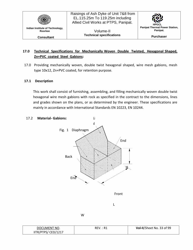
17.0 Technical Specifications for Mechanically Woven Double Twisted, Hexagonal Shaped,
Zn+PVC coated Steel Gabions:
17.0 Providing mechanically woven, double twist hexagonal shaped, wire mesh gabions, mesh
type 10x12, Zn+PVC coated, for retention purpose.
17.1 Description
This work shall consist of furnishing, assembling, and filling mechanically woven double twist
hexagonal wire mesh gabions with rock as specified in the contract to the dimensions, lines
and grades shown on the plans, or as determined by the engineer. These specifications are
mainly in accordance with International Standards EN 10223, EN 10244.
17.2 Material- Gabions: Li
d
Fig. 1 Diaphragm
End
Back
H
End
Front
L
W
Indian Institute of Technology,
Roorkee
Consultant
Raisings of Ash Dyke of Unit 7&8 from EL.115.25m To 119.25m including
Allied Civil Works at PTPS, Panipat.
Volume-II Technical specifications
HPGCL Panipat Thermal Power Station,
Panipat.
Purchaser
DOCUMENT NO. IITR/PTPS/ CED/1217
REV. : R1 Vol-II/Sheet No. 34 of 99
17.2.1 Wire:
All tests on the mesh, lacing wire and selvedge wire must be performed prior to
manufacturing the mesh.
Tensile strength: The wire used for the manufacture of Mesh shall have a tensile strength
minimum 350 N/mm2 in accordance with EN 10223-3. Wire tolerances (Table 3) are in
accordance with EN 10218 (Class T1).
Elongation: Elongation shall not be less than 10%, in accordance with EN 10223-3. Test must
be carried out on a sample of at least 25 cm length.
17.2.2 Internal Connecting Wires:
Cross Ties/ stiffener wire: Diameter 2.2 mm, Zinc coated wire with PVC coating,
3.2mm when measured with PVC coating.
17.2.3 Zinc Coating
i). Zinc coating: Minimum quantities of Zinc shown at Table 1 shall meet the requirements of
EN 10244-2 (Table 1 and Class A).
ii). Adhesion of zinc coating: The adhesion of the zinc coating to the wire shall be such that,
when the wire is wrapped six turns around a mandrel having four times the diameter of the
wire, it does not flake or crack when rubbing it with the bare fingers in accordance with
EN 10244.
17.2.4 PVC (Polyvinyl Chloride) Coating
PVC coating thickness: Nominal – 0.5 mm, Minimum – 0.38 mm; Specific weight: 1.3 kg/dm3
– 1.35 kg/m3 in accordance with ISO 1183. Hardness: between 50 and 60 Shore D, according
to ISO 868.
Tensile strength: Higher than 21 MPa, according to ISO 527 Elongation at
break: not less than 200% in accordance with ISO 527. UV Stabilized
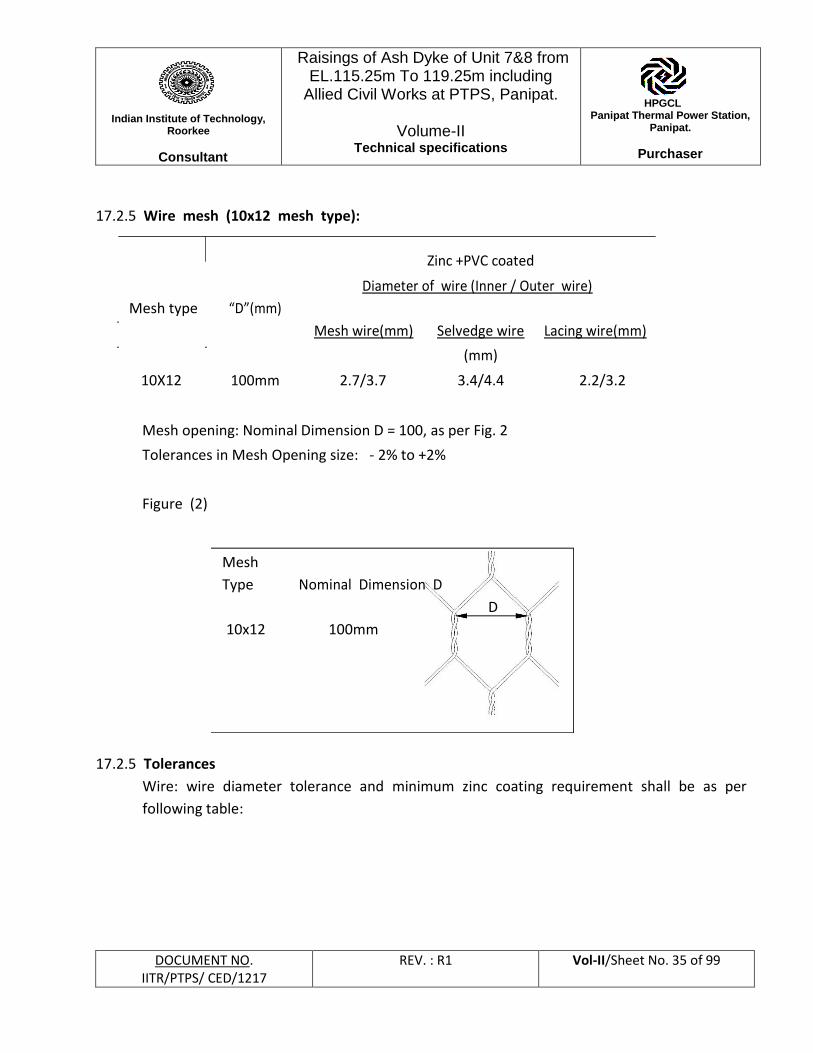
Indian Institute of Technology,
Roorkee
Consultant
Raisings of Ash Dyke of Unit 7&8 from EL.115.25m To 119.25m including
Allied Civil Works at PTPS, Panipat.
Volume-II Technical specifications
HPGCL Panipat Thermal Power Station,
Panipat.
Purchaser
DOCUMENT NO. IITR/PTPS/ CED/1217
REV. : R1 Vol-II/Sheet No. 35 of 99
17.2.5 Wire mesh (10x12 mesh type):
Zinc +PVC coated
Mesh type “D”(mm)
Diameter of wire (Inner / Outer wire)
Mesh wire(mm) Selvedge wire Lacing wire(mm)
(mm)
10X12 100mm 2.7/3.7 3.4/4.4 2.2/3.2
Mesh opening: Nominal Dimension D = 100, as per Fig. 2
Tolerances in Mesh Opening size: - 2% to +2%
Figure (2)
Mesh
Type Nominal Dimension D
10x12 100mm
D
17.2.5 Tolerances
Wire: wire diameter tolerance and minimum zinc coating requirement shall be as per
following table:
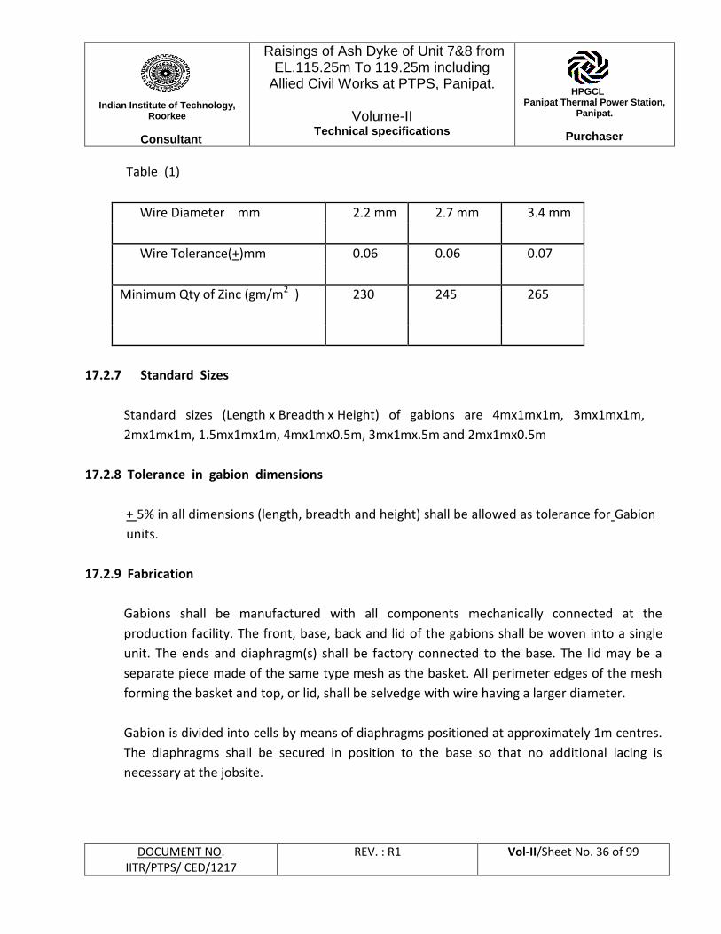
Indian Institute of Technology,
Roorkee
Consultant
Raisings of Ash Dyke of Unit 7&8 from EL.115.25m To 119.25m including
Allied Civil Works at PTPS, Panipat.
Volume-II Technical specifications
HPGCL Panipat Thermal Power Station,
Panipat.
Purchaser
DOCUMENT NO. IITR/PTPS/ CED/1217
REV. : R1 Vol-II/Sheet No. 36 of 99
Table (1)
Wire Diameter mm 2.2 mm 2.7 mm 3.4 mm
Wire Tolerance(+)mm 0.06 0.06 0.07
Minimum Qty of Zinc (gm/m2 ) 230 245 265
17.2.7 Standard Sizes
Standard sizes (Length x Breadth x Height) of gabions are 4mx1mx1m, 3mx1mx1m,
2mx1mx1m, 1.5mx1mx1m, 4mx1mx0.5m, 3mx1mx.5m and 2mx1mx0.5m
17.2.8 Tolerance in gabion dimensions
+ 5% in all dimensions (length, breadth and height) shall be allowed as tolerance for Gabion
units.
17.2.9 Fabrication
Gabions shall be manufactured with all components mechanically connected at the
production facility. The front, base, back and lid of the gabions shall be woven into a single
unit. The ends and diaphragm(s) shall be factory connected to the base. The lid may be a
separate piece made of the same type mesh as the basket. All perimeter edges of the mesh
forming the basket and top, or lid, shall be selvedge with wire having a larger diameter.
Gabion is divided into cells by means of diaphragms positioned at approximately 1m centres.
The diaphragms shall be secured in position to the base so that no additional lacing is
necessary at the jobsite.
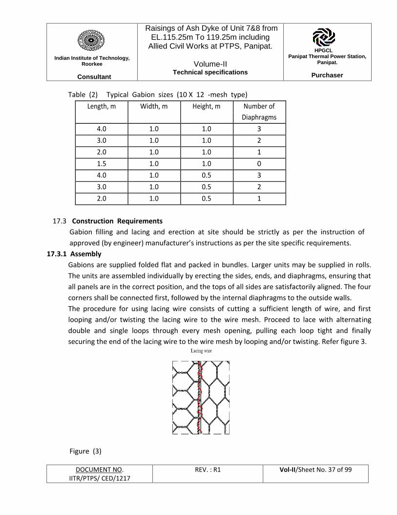
Indian Institute of Technology,
Roorkee
Consultant
Raisings of Ash Dyke of Unit 7&8 from EL.115.25m To 119.25m including
Allied Civil Works at PTPS, Panipat.
Volume-II Technical specifications
HPGCL Panipat Thermal Power Station,
Panipat.
Purchaser
DOCUMENT NO. IITR/PTPS/ CED/1217
REV. : R1 Vol-II/Sheet No. 37 of 99
Table (2) Typical Gabion sizes (10 X 12 -mesh type)
Length, m Width, m Height, m Number of
Diaphragms
4.0 1.0 1.0 3
3.0 1.0 1.0 2
2.0 1.0 1.0 1
1.5 1.0 1.0 0
4.0 1.0 0.5 3
3.0 1.0 0.5 2
2.0 1.0 0.5 1
17.3 Construction Requirements
Gabion filling and lacing and erection at site should be strictly as per the instruction of
approved (by engineer) manufacturer’s instructions as per the site specific requirements.
17.3.1 Assembly
Gabions are supplied folded flat and packed in bundles. Larger units may be supplied in rolls.
The units are assembled individually by erecting the sides, ends, and diaphragms, ensuring that
all panels are in the correct position, and the tops of all sides are satisfactorily aligned. The four
corners shall be connected first, followed by the internal diaphragms to the outside walls.
The procedure for using lacing wire consists of cutting a sufficient length of wire, and first
looping and/or twisting the lacing wire to the wire mesh. Proceed to lace with alternating
double and single loops through every mesh opening, pulling each loop tight and finally
securing the end of the lacing wire to the wire mesh by looping and/or twisting. Refer figure 3.
Figure (3)
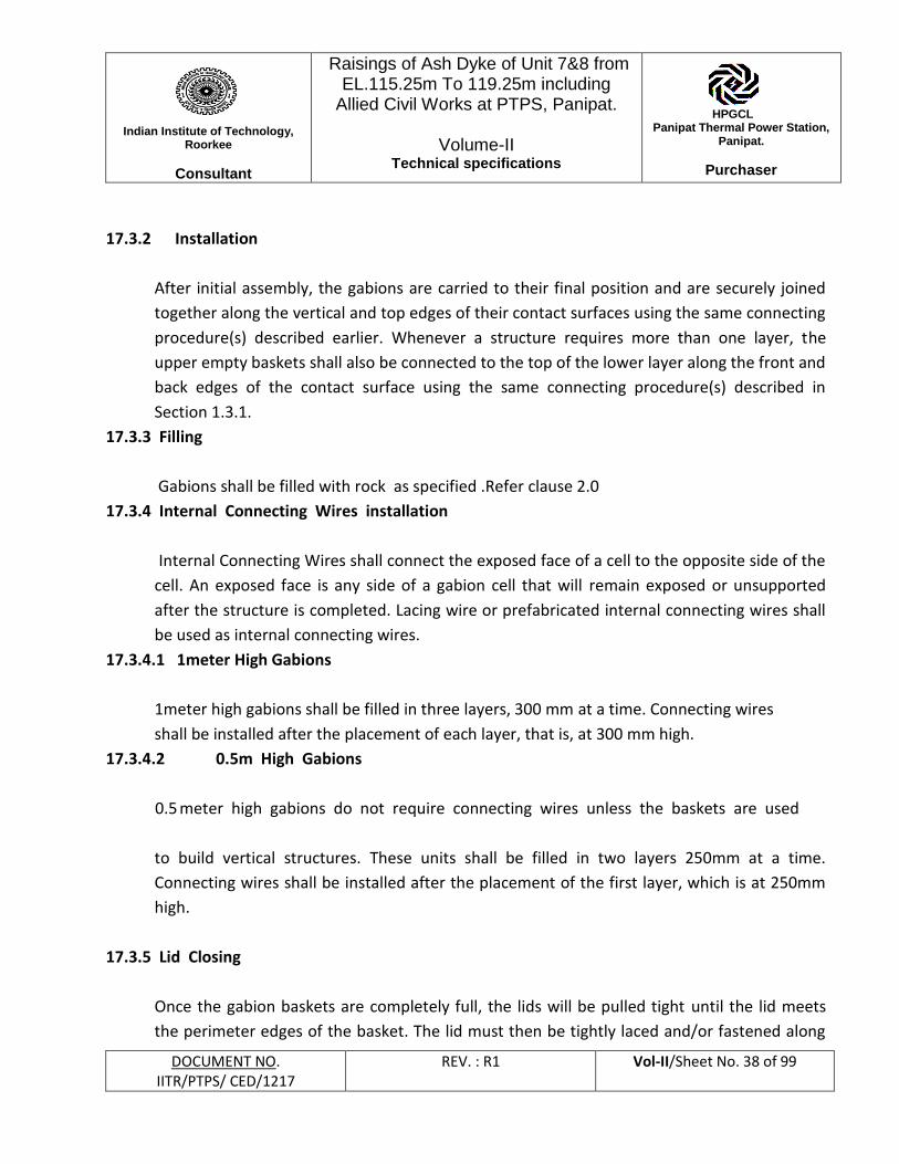
Indian Institute of Technology,
Roorkee
Consultant
Raisings of Ash Dyke of Unit 7&8 from EL.115.25m To 119.25m including
Allied Civil Works at PTPS, Panipat.
Volume-II Technical specifications
HPGCL Panipat Thermal Power Station,
Panipat.
Purchaser
DOCUMENT NO. IITR/PTPS/ CED/1217
REV. : R1 Vol-II/Sheet No. 38 of 99
17.3.2 Installation
After initial assembly, the gabions are carried to their final position and are securely joined
together along the vertical and top edges of their contact surfaces using the same connecting
procedure(s) described earlier. Whenever a structure requires more than one layer, the
upper empty baskets shall also be connected to the top of the lower layer along the front and
back edges of the contact surface using the same connecting procedure(s) described in
Section 1.3.1.
17.3.3 Filling
Gabions shall be filled with rock as specified .Refer clause 2.0
17.3.4 Internal Connecting Wires installation
Internal Connecting Wires shall connect the exposed face of a cell to the opposite side of the
cell. An exposed face is any side of a gabion cell that will remain exposed or unsupported
after the structure is completed. Lacing wire or prefabricated internal connecting wires shall
be used as internal connecting wires.
17.3.4.1 1meter High Gabions
1meter high gabions shall be filled in three layers, 300 mm at a time. Connecting wires
shall be installed after the placement of each layer, that is, at 300 mm high.
17.3.4.2 0.5m High Gabions
0.5 meter high gabions do not require connecting wires unless the baskets are used
to build vertical structures. These units shall be filled in two layers 250mm at a time.
Connecting wires shall be installed after the placement of the first layer, which is at 250mm
high.
17.3.5 Lid Closing
Once the gabion baskets are completely full, the lids will be pulled tight until the lid meets
the perimeter edges of the basket. The lid must then be tightly laced and/or fastened along
Indian Institute of Technology,
Roorkee
Consultant
Raisings of Ash Dyke of Unit 7&8 from EL.115.25m To 119.25m including
Allied Civil Works at PTPS, Panipat.
Volume-II Technical specifications
HPGCL Panipat Thermal Power Station,
Panipat.
Purchaser
DOCUMENT NO. IITR/PTPS/ CED/1217
REV. : R1 Vol-II/Sheet No. 39 of 99
all edges, ends and tops of diaphragm(s) in the same manner as described in earlier sections.
17.3.6 Mesh cutting and folding
Where shown on the drawings or otherwise directed by the engineer, the gabions shall be
cut, folded and fastened together to suit existing site conditions. The mesh must be cleanly
cut and surplus mesh either folded back or overlapped so that it can be securely fastened
together with lacing wire or fasteners in the manner described in earlier Section. Any
reshaped gabions shall be assembled, installed, filled and closed as specified in the previous
sections.
17.4 Method of Measurement
The payment quantities for excavation shall be determined by the outside limits of the
gabion structure. Quantities will be determined from cross sections and the linear distance,
and paid for under the appropriate bid items.
The quantity to be paid for “In place gabions” shall be the number of gabions of respective
sizes. Project conditions and material availability will determine the actual size of gabions to
be used.
Excavated material beyond the limits of the gabions shall be backfilled with gravel, crushed
rock or other material approved by the engineer.
17.5 Basis of Payment
Accepted gabions will be paid for at the unit price for each pay item included in the
contract.
17.6 Testing and Acceptance criteria
The material should get approval from the Consultant/ Purchaser before the actual supply
start. The manufacturer of the Gabion facing unit should provide “Manufacturers Test
Certificate’ and Quality Conformity Certificate for the material with every lot/shipment.
Indian Institute of Technology,
Roorkee
Consultant
Raisings of Ash Dyke of Unit 7&8 from EL.115.25m To 119.25m including
Allied Civil Works at PTPS, Panipat.
Volume-II Technical specifications
HPGCL Panipat Thermal Power Station,
Panipat.
Purchaser
DOCUMENT NO. IITR/PTPS/ CED/1217
REV. : R1 Vol-II/Sheet No. 40 of 99
Tensile strength test and zinc coating test on basic wire shall be done on one sample per
every 10,000 numbers of units supplied. Before approval of the material at least one sample
shall be got tested from Indian Institute of Technology, Roorkee in the presence of the
consultant/ Purchaser.
PVC Coating Thickness: The thickness of the PVC coating shall be determined on a randomly
chosen individual piece of wire removed from the coil at 3 places 1 metre apart.
Measure with a micrometer the diameter of the galvanized steel wire with PVC coating.
Determine the thickness of the PVC coating by stripping the PVC coating from the wire and
measure the reduced diameter with a micrometer. The thickness of the coating is the
difference between the diameter of the galvanized steel wire with PVC coating and the
measured diameter of the galvanized steel wire divided by two. The thickness values should
be as per clause 1.2.4. While removing the PVC coating by stripping, take care not to remove
any of the metallic surfaces.
17.6.1 Selvedge strength test:
i. A tensile test on mesh sample shall be carried out in order to estimate selvedge
strength test. The test shall be carried out as per procedure outlined below. The
selvedge strength shall be minimum 25 kN/m.
ii. Take a DT mesh of approximately 1.0 m width.
iii. The height of the sample shall be such that after selvedging on both the sides (1m),
there shall be at least two mesh repetitions between the two selvedged wires, so
that effective height of the sample shall be more than 300 mm.
iv. Sample shall be loaded on the UTM in a direction parallel to twist, with the samples
being gripped at the two selvedged wires & not mesh twist.
vi. The distance between the two selvedge wires shall be recorded as Initial gauge
length.
Indian Institute of Technology,
Roorkee
Consultant
Raisings of Ash Dyke of Unit 7&8 from EL.115.25m To 119.25m including
Allied Civil Works at PTPS, Panipat.
Volume-II Technical specifications
HPGCL Panipat Thermal Power Station,
Panipat.
Purchaser
DOCUMENT NO. IITR/PTPS/ CED/1217
REV. : R1 Vol-II/Sheet No. 41 of 99
Distance between the two end gripping points (pins) along the width of the sample shall be
recorded as the unit width under test. The width shall be at least 700 mm. The load shall be
applied gradually to the sample and the test be continued till the break point.
The peak load and the % elongation shall be recorded.
The strength of the selvedge connection shall be (peak load/unit width under test) expressed
in kN/m.
NB. If the sample slips at any of the gripping point during the test, such a test shall be
discarded and a new sample shall be taken.
17.6.2 Eligibility of Manufacturer:
Manufacturer of woven steel wire double twist hexagonal mesh gabions shall have:
• In-house facility to test the tensile strength of the basic GI wire and Mesh Panels using
computerized testing facilities which forms mechanically woven double twisted mesh
panels
• In-house test facility for zinc coating test.
• A valid ISO 9001:2008 accreditation from an internationally accredited organization
such as Lloyd’s Register for its Gabion manufacturing facilities.
• Manufacturing experience of mechanically woven Gabions of minimum 7 years
internationally or in India as per International standards.
• The Manufacturer / Supplier shall have existence in India for more than 7 years from
the date of this tender notice.
• Manufacturer of woven double twist hexagonal steel wire mesh gabions shall have
proven experience in supply and designing of retention works in India for at least
7 years.
• Experience of supplying minimum 20,000 cum of Gabions. Supplier shall provide
performance certificate of material supplied to government department/Public sector
undertaking.
The Manufacturer / Supplier should not have a history of poor performance such as
abandoning the works, financial failures, blacklisting. If it is observed, Manufacturer /
Supplier will be automatically disqualified.
Indian Institute of Technology,
Roorkee
Consultant
Raisings of Ash Dyke of Unit 7&8 from EL.115.25m To 119.25m including
Allied Civil Works at PTPS, Panipat.
Volume-II Technical specifications
HPGCL Panipat Thermal Power Station,
Panipat.
Purchaser
DOCUMENT NO. IITR/PTPS/ CED/1217
REV. : R1 Vol-II/Sheet No. 42 of 99
18. Providing and placing stones in Gabions:
18.1 Material Rock:
Rock for the Gabion facia shall be hard, angular to round, durable and of such quality that
they shall not disintegrate on exposure to water or weathering during the life of the
structure. The rocks shall range between 150 mm to 250 mm for 10x12 type mesh. Each
range of sizes may allow for a variation of 5% oversize rock by number of particles, or 5%
undersize rock by number of particles, or both. The size of any oversize rock shall allow for
the placement of minimum of three layers of rock must be achieved when filling the 1 m high
units and a minimum of two layers for the 0.50 m high units. Suitable coal pick stone (reject
coal boulders) available in Panipat Thermal Plant area shall be used as rock for gabion wall.
The coal pick stone shall be issued free of cost to the contractor on ‘as is where is’ basis
and contractor shall arrange for breaking them further in the require sizes. Loading,
Unloading, handling and transportation of the same from Power Plant to work site shall be at
contractors own cost and deemed to be covered in his quoted unit rate.
18.2 Placement of stones in Gabion Facia Section.
The facing section shall be filled with rock in a careful way to get good horizontal and vertical
alignment. During the filling operation skilled manual stone placement is required to
minimize voids. The maximum permitted porosity of stone filling shall be 40%. For vertical or
near vertical structures the exterior of the basket may be carefully hand placed to give a
neat, flat, and compact appearance. Care shall be taken when placing fill material to ensure
that the sheathing on the PVC coated baskets is not damaged. The facing stones should
orient in such a way to get their flat surfaces facing to the front.
The cells shall be filled in stages so that local deformation may be avoided. At no time shall
any cell be filled to a depth exceeding 0.30 m higher than the adjoining cell. It is also
recommended to slightly overfill the baskets by 25mm to 50 mm to allow for settlement of
the rock
Internal Connecting Wires with lacing wire shall connect the exposed face of a cell to the
opposite side of the cell. Internal Connecting performed stiffeners shall connect the exposed
face of a cell to the adjacent side of the cell. Preformed stiffeners are installed at 45° to the
Indian Institute of Technology,
Roorkee
Consultant
Raisings of Ash Dyke of Unit 7&8 from EL.115.25m To 119.25m including
Allied Civil Works at PTPS, Panipat.
Volume-II Technical specifications
HPGCL Panipat Thermal Power Station,
Panipat.
Purchaser
DOCUMENT NO. IITR/PTPS/ CED/1217
REV. : R1 Vol-II/Sheet No. 43 of 99
face (side of the unit), extending an equal distance along each side to be braced
(approximately 300 mm). An exposed face is any side of Gabion facia and tail with double
twist hexagonal mesh units that will be exposed or unsupported after the structure is
completed.
18.3 Method of Measurement:
Measurement shall be in volume from cross sections and longitudinal sections.
18.4 Basis of Payment:
Payment should be per unit of cubic meter.
18.5 Acceptance:
The size of the stone for filling in 10x12 mesh shall be 150 mm-250mm.
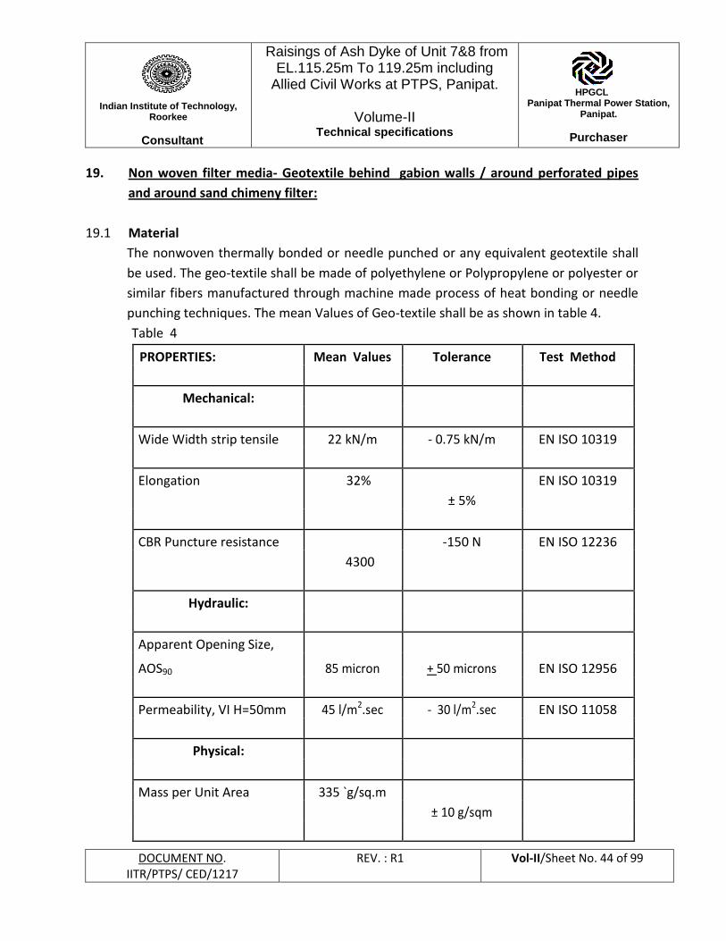
Indian Institute of Technology,
Roorkee
Consultant
Raisings of Ash Dyke of Unit 7&8 from EL.115.25m To 119.25m including
Allied Civil Works at PTPS, Panipat.
Volume-II Technical specifications
HPGCL Panipat Thermal Power Station,
Panipat.
Purchaser
DOCUMENT NO. IITR/PTPS/ CED/1217
REV. : R1 Vol-II/Sheet No. 44 of 99
19. Non woven filter media- Geotextile behind gabion walls / around perforated pipes
and around sand chimeny filter:
19.1 Material
The nonwoven thermally bonded or needle punched or any equivalent geotextile shall
be used. The geo-textile shall be made of polyethylene or Polypropylene or polyester or
similar fibers manufactured through machine made process of heat bonding or needle
punching techniques. The mean Values of Geo-textile shall be as shown in table 4.
Table 4
PROPERTIES: Mean Values Tolerance Test Method
Mechanical:
Wide Width strip tensile 22 kN/m - 0.75 kN/m EN ISO 10319
Elongation 32%
± 5%
EN ISO 10319
CBR Puncture resistance
4300
-150 N EN ISO 12236
Hydraulic:
Apparent Opening Size,
AOS90 85 micron + 50 microns EN ISO 12956
Permeability, VI H=50mm 45 l/m2.sec - 30 l/m2.sec EN ISO 11058
Physical:
Mass per Unit Area 335 `g/sq.m
± 10 g/sqm
Indian Institute of Technology,
Roorkee
Consultant
Raisings of Ash Dyke of Unit 7&8 from EL.115.25m To 119.25m including
Allied Civil Works at PTPS, Panipat.
Volume-II Technical specifications
HPGCL Panipat Thermal Power Station,
Panipat.
Purchaser
DOCUMENT NO. IITR/PTPS/ CED/1217
REV. : R1 Vol-II/Sheet No. 45 of 99
Composition:
About 70% polypropylene and rest shall be polyethylene or any other equivalent
material.
19.2 Method of measurement :
Quantity of filter geotextile shall be determined from cross sections and the linear
distance, and paid for under the appropriate bid items.
19.3 Basis of Payment :
Accepted filter geotextile shall be paid for at the unit price (per square metre area) for each
pay item included in the contract.
19.4 Method of Testing:
The supplier has to submit a Quality conformity certificate and Manufactures test certificate
for the parameters indicated in table 3 for every lot/shipment. Before approval of the
material by the consultant/ Purchaser at least one sample shall be got tested from IIT
Roorkee in the presence of the consultant/ Purchaser.
Indian Institute of Technology,
Roorkee
Consultant
Raisings of Ash Dyke of Unit 7&8 from EL.115.25m To 119.25m including
Allied Civil Works at PTPS, Panipat.
Volume-II Technical specifications
HPGCL Panipat Thermal Power Station,
Panipat.
Purchaser
DOCUMENT NO. IITR/PTPS/ CED/1217
REV. : R1 Vol-II/Sheet No. 46 of 99
20. High strength Geogrid as basal reinforcement:
20.1 Description:
This work shall consist of furnishing and placing uniaxial high strength geogrid or approved
equivalent Geogrid over a soft foundation soil to construct an embankment over it. This
geogrid layer acts as a reinforcement layer between soft soil and embankment fill soil.
20.2 Materials:
High strength geogrids, with low creep characteristics and stress-strain characteristics to
mobilize the desired tension at 5% strain shall be used the geogrids may be made from
Polyester (PET). The geogrids shall have on outer protective coating of low density
polyethylene sheath. The tensile strength of geogrid at 5% strain shall not be less than 250
kN/m, which value is the required tensile strength of the reinforcing geogrid, shall be on
basis of long term design strength value of the particular grade of geogrid proposed. The
long term design strength shall be obtained by reducing the short term or ultimate tensile
strength by the reduction factors as specified in BS 8006-1995. viz. reduction factor for
creep, mechanical damage, environmental damage and extrapolation of data.
20.3 Acceptance of Geogrids:
Geogrids specified as reinforcement in the basal mattress for ground improvement are high
strength geogrids. These have to develop the requisite design tensile strength at less than
5% strain on long term strength basis. Geogrids made from polyester (PET) or Polyvinyl
Alcohol (PVA / PA) are recommended because they have superior stress – strain and creep
properties. The manufacturer shall provide the following data and certificates:
Note: At least one sample shall be got tested from IIT Roorkee in the presence of the
consultant/ Purchaser and only then approval shall be accorded by the purchaser.
20.3.1 Partial material factors as per BS 8006:1995;
Partial reduction factors of creep of 120 years design life as well as of shorter durations.
Partial reduction factors of mechanical damage.
Partial reduction factors of environmental effects.
Partial material factors to extrapolate the data
20.3.2 Stress strain curves of different loading durations.
Indian Institute of Technology,
Roorkee
Consultant
Raisings of Ash Dyke of Unit 7&8 from EL.115.25m To 119.25m including
Allied Civil Works at PTPS, Panipat.
Volume-II Technical specifications
HPGCL Panipat Thermal Power Station,
Panipat.
Purchaser
DOCUMENT NO. IITR/PTPS/ CED/1217
REV. : R1 Vol-II/Sheet No. 47 of 99
20.3.3 The manufacturer shall provide BBA certificate to use the geogrids as reinforcing geogrids.
20.3.4 The manufacturer shall provide ISO: 9002 certificate of manufacturing process.
20.3.5 The manufacturer/ supplier shall have experience to use in similar ground improvement
projects in India and/ or abroad geogrids of the type he proposes to use in the project. He
shall provide proof of the same, by providing adequate information concerning such
projects. Geogrids shall not be accepted in the absence of such information
20.4 Geogrid shall be supplied in roll length of not less than 100m and roll width not less
than 4.5m.
Note: Uncertified geogrids whose quality and stress – strain properties are not established shall not
be accepted. Use of lower quality geogrids may result to higher strains in the geogrids such
as over – stress may even lead to the rupture of geogrids and instability of the earth
structure.
Quality of geogrids is very important in this application, as
I. The geogrid may be subjected certain amount unanticipated strains due to local settlements
of clay in some places.
II. The geogrids used in the basal mattress would be under water table for most part of the year
and the water is likely to be having some salts etc. Over a period of years, the salts may act
to reduce the strength of the geogrids. Hence adequate partial reduction factor against
environmental damage has to be used.
20.5 Eligibility Criteria for Manufacturer:
The manufacturing unit of geogrid should have ISO 9001:2008 accreditation from an
internationally accredited organization such as Lloyd’s Register or equivalent certification for
its quality procedures. In-house facility to test the tensile strength of the geogrid using
computerized testing facilities.
20.6 Delivery and Storage:
Each roll delivered to site shall be clearly labeled with grade, batch number and wrapped in
material that will protect the geogrid including the ends of rolls from damage due to
Indian Institute of Technology,
Roorkee
Consultant
Raisings of Ash Dyke of Unit 7&8 from EL.115.25m To 119.25m including
Allied Civil Works at PTPS, Panipat.
Volume-II Technical specifications
HPGCL Panipat Thermal Power Station,
Panipat.
Purchaser
DOCUMENT NO. IITR/PTPS/ CED/1217
REV. : R1 Vol-II/Sheet No. 48 of 99
shipment, water, sunlight and contaminants. The protective wrapping shall be maintained
during shipment and storage.
20.7 Equipment:
All equipment necessary for the placing of the geogrid shall be approved before work will be
permitted to begin.
20.8 Construction Requirements:
20.8.1 Geogrid packaging and storing – During storage, geogrid rolls shall be elevated off the
ground and adequately covered to protect them from site construction damage,
precipitation, extended ultraviolet radiation including sunlight, chemicals that are strong
acids or strong bases, flames including welding sparks, and any other environmental
condition that may damage the physical property values of the geogrid.
20.8.2 Site preparation – The top foundation soil shall be free from undulations and
prepared to the level as indicated in the construction drawings or as directed by the
Engineer.
20.8.3 Installation – The geogrid shall be laid at the proper elevation and alignment as shown on
the construction drawings. It shall be placed with main strength direction oriented
perpendicular to centerline of the embankment.
The geogrid shall be installed in accordance with the installation guidelines provided by the
manufacturer or as directed by the Engineer. It may be temporarily secured in place with
ties, staples, pins, sand bags as required by fill properties, fill placement procedures or
weather conditions or as directed by the Engineer.
20.8.4 Joints, and overlaps – An overlap of 300 mm or as indicated by Engineer shall be
provided between the adjacent rolls. There shall be no joints along the length of geogrid.
20.9 Method of Measurement:
The Geogrid shall be measured by the square meter or fraction thereof in place. Excavation,
Indian Institute of Technology,
Roorkee
Consultant
Raisings of Ash Dyke of Unit 7&8 from EL.115.25m To 119.25m including
Allied Civil Works at PTPS, Panipat.
Volume-II Technical specifications
HPGCL Panipat Thermal Power Station,
Panipat.
Purchaser
DOCUMENT NO. IITR/PTPS/ CED/1217
REV. : R1 Vol-II/Sheet No. 49 of 99
backfill, bedding and cover material are separate pay items.
20.10 Basis of Payment:
Unless otherwise noted in the Plans, the accepted quantity of Geogrid complete in place
shall be paid for at the contract unit price per square meter. This price shall constitute full
compensation for all work materials, labor and other incidentals required to complete the
work in accordance with these Specifications.
Indian Institute of Technology,
Roorkee
Consultant
Raisings of Ash Dyke of Unit 7&8 from EL.115.25m To 119.25m including
Allied Civil Works at PTPS, Panipat.
Volume-II Technical specifications
HPGCL Panipat Thermal Power Station,
Panipat.
Purchaser
DOCUMENT NO. IITR/PTPS/ CED/1217
REV. : R1 Vol-II/Sheet No. 50 of 99
21.0 Grass Turfing:
21.1 Doob Grass:
Grass shall be fresh 'Doob' grass free from weed and rank vegetation but having 'Rhizomes'
with sufficient nodes shall be approved by the Engineer-in-Charge before planting.
21.2 Operations:
The soil shall be suitably moistened and then operation of planting grass shall be
commenced. The grass shall be dibbed at 5 cm. or other spacing as described in the drawing.
Planting shall be done in either direction at 5 cm spacing or as specified in the drawing. The
grass shall be maintained for 30 days or more till the grass forms a thick lawn free from dead
grass and weeds.
21.3 Precautions:
During the maintenance period, any irregularities arising in ground levels due to watering or
due to trampling by labour or due to cattle straying thereon, shall be constantly maintained
up to the proper levels, with earth as available at site or brought from outside as necessary.
Constant watch shall be maintained to ensure that dead patches are replanted and
undesirable growth such as weeds, rhizomes and tubes are weeded out.
21.4 Turfing with jute geo textile and seedlings of grass:
Jute geo textile 500 GSM with aperture size100mmx100mm shall be laid on the
downstream slopes of ash dyke. Jute geo textile to be held in position by wooden
pegs/8mmdia MS bars at 3 meter centre to center followed by providing and spreading,
seedlings of grass, watering etc. complete till the grass establishes itself uniformly. The rate
shall include the cost of all materials; watering charges and maintenance etc. till the grass
forms a thick lawn free from dead grass and weeds. Constant watch shall be maintained to
ensure that dead patches are replanted and undesirable growth such as weeds, rhizomes
and tubes are weeded out.
21.5 Measurement & Payment: Length and breadth shall be measured in meters correct to the
second place of decimal. The area of the turfing shall be measured for payment in sq.m.
correct to the second place of decimal.
Indian Institute of Technology,
Roorkee
Consultant
Raisings of Ash Dyke of Unit 7&8 from EL.115.25m To 119.25m including
Allied Civil Works at PTPS, Panipat.
Volume-II Technical specifications
HPGCL Panipat Thermal Power Station,
Panipat.
Purchaser
DOCUMENT NO. IITR/PTPS/ CED/1217
REV. : R1 Vol-II/Sheet No. 51 of 99
22.0 Brick Masonry Works:
22.1 Scope:
This section covers the furnishing of all labour, materials and equipments and performing of
all operations required for the supply of materials and erection work and incidental items
pertinent thereto in drains, road curbs etc. all in accordance with the drawings and these
specifications.
22.2 General requirements:
22.2.1 Masonry products such as face bricks, common bricks and tiles shall be products of
producers or suppliers approved by the Engineer.
22.2.2 Delivery, storage and handling of Materials shall be as follows:
(i) All materials shall be delivered to the site, stored and handled so as to prevent
inclusion of foreign substances, damage by breakage, exposure to the weather and
contact with the soil.
(ii) Cementatious materials shall be delivered in unbroken containers or packages and
stored in weatherproof enclosures.
22.3 Materials:
22.3.1 Cement shall be ordinary Portland cement of 33-Grade and 43-Grade conforming to IS: 269
and IS: 8112 or any other type approved by the Purchaser.
22.3.2 Water for mortar shall be clean and potable and free of salts, iron and injurious amounts of
organic matter.
22.3.3 Sand shall conform to the requirements of IS -2116 (Latest edition)
22.3.4 Fly Ash Bricks conforming to relevant IS Code only shall be used. In case of non-availability of
Fly Ash Bricks, common clay bricks may be used with the written approval of Engineer-in-
Charge. Common burnt clay bricks and face bricks shall conform to the requirements of IS:
1077 and shall be of uniform colour, strength and size. Bricks shall not absorb more than
20% of their own dry weight when soaked in water.
22.3.5 Crushing strength bricks shall not be less than 100 kg/sq.cm.
Indian Institute of Technology,
Roorkee
Consultant
Raisings of Ash Dyke of Unit 7&8 from EL.115.25m To 119.25m including
Allied Civil Works at PTPS, Panipat.
Volume-II Technical specifications
HPGCL Panipat Thermal Power Station,
Panipat.
Purchaser
DOCUMENT NO. IITR/PTPS/ CED/1217
REV. : R1 Vol-II/Sheet No. 52 of 99
22.3.6 Wall ties shall be 6mm mild steel "U" or "Z" shaped 50mm less in depth than the width of
the wall into which they are built, spaced 400mm centers vertically or provided at every fifth
course.
22.3.7 Reinforcement for masonry walls wherever required shall be of mild steel 8mm diameter tor
steel bars welded/tied to the wall ties at every fifth course of brickwork.
22.3.8 Samples of all materials shall be submitted for the approval of the Engineer.
22.3.9 Mortar of specified proportions as shown in the construction drawings shall be mixed by
volume with just enough water added to produce a workable mixture. Only freshly prepared
mortar shall be used. Mortar shall conform the requirements of IS: 1925.
22.4 Bond & Coursing:
22.4.1 All masonry walls shall be laid with horizontal courses level and true in English bond. All
masonry units shall be laid up in full beds of mortar with all units butted solidly against
adjacent units with mortar in between.
22.4.2 All masonry units having appreciable water absorption potential shall be soaked as per
relevant IS code.
22.4.3 Vertical surfaces of all masonry walls and partitions shall be plumb and true to line on
uneven surface with maximum total variation of 25mm in any plane or 12.5 mm in 5 meters.
22.4.4 Where two walls meet or intersect, the masonry course shall be carried up together,
bonding at least fifty percent of the units at the intersection.
22.4.5 Horizontal surfaces of masonry not being worked on shall be protected from the natural
elements by the use of non-staining waterproof coverings, properly secured in place.
22.4.6 Brick tiles where shown in drawings shall be laid with staggered vertical joints and shall be
bonded to the brick walls.
22.4.7 Masonry in contact with structural steel including beams and columns shall be anchored to
the steel works as indicated in the drawings.
22.5 Masonry joints:
22.5.1 All joints in masonry wall surfaces to receive cement plaster shall be raked out to a depth of
12mm to create mechanical bond for the plaster finish.
22.5.2 Joints in exterior walls to be left exposed shall be neatly tooled with a weathered joint.
22.5.3 Where masonry shuts penetrating built-in-terms such as doors frames etc. the joints shall be
6mm wide and raked to a depth of 20mm for subsequent caulking.
Indian Institute of Technology,
Roorkee
Consultant
Raisings of Ash Dyke of Unit 7&8 from EL.115.25m To 119.25m including
Allied Civil Works at PTPS, Panipat.
Volume-II Technical specifications
HPGCL Panipat Thermal Power Station,
Panipat.
Purchaser
DOCUMENT NO. IITR/PTPS/ CED/1217
REV. : R1 Vol-II/Sheet No. 53 of 99
22.5.4 Where openings are left in masonry fixing doors, windows etc. or where masonry is
discontinued for extending at a later date, the masonry work should be left at an angle not
steeper than 60 degree.
22.6 Cleaning:
22.6.1 All exposed brickwork shall be scrubbed down with clean water and rinsed thoroughly.
22.6.2 All work stained or discolored during the process of cleaning shall be replaced by the
Contractor at his own expenses.
22.6.3 Green work shall be protected from the effects of sun, rain etc. by suitable covering. All the
masonry work shall be kept constantly moist on the faces for a period of seven days.
22.6.4 The contractor shall carry out all scaffolding and planking necessary for efficient execution of
work at all levels. The scaffolding and planking shall be of the best material and the
contractor shall be responsible to ensure safety of personnel working on them at all levels.
22.6.5 At the end of construction, the contractor shall ensure proper plugging of all openings made
for supporting the scaffolding.
22.7 Measurement & Payment.
The length, height and thickness of Brick Masonry work shall be measured in meter correct
to third place of decimal. The thickness of wall shall be measured excluding the thickness of
plaster. Only specified dimension shall be owed, anything extra shall be ignored. The
quantity shall be calculated in cubic meter nearest to third place of decimal. No deduction
shall be made nor extra payment made for making grooves and weep holes in masonry. The
cost of testing of all materials shall be borne by the contractor and no separate payment
shall be made on account of this.
Indian Institute of Technology,
Roorkee
Consultant
Raisings of Ash Dyke of Unit 7&8 from EL.115.25m To 119.25m including
Allied Civil Works at PTPS, Panipat.
Volume-II Technical specifications
HPGCL Panipat Thermal Power Station,
Panipat.
Purchaser
DOCUMENT NO. IITR/PTPS/ CED/1217
REV. : R1 Vol-II/Sheet No. 54 of 99
23.0 Dry Brick Pitching:
23.1 Burnt clay bricks, for general turfing work shall be conforming to IS: 1077 (latest). Fly ash
lime brick and clay – fly ash bricks shall conform to IS: 12894 (latest) and IS: 13757(latest)
respectively. The class of bricks shall be a minimum of class-10. The ash brick’ conforming to
relevant IS codes only shall be used. In case of non- availability of fly ash bricks within a lead
of 100 km, common clay bricks may be used with the written permission of Engineer-in-
charge.
23.2 Bricks for turfing work shall be hand/machine made, well burnt of uniform size, shape, edges
and uniform cherry red colour. Bricks shall give a clear ringing sound when struck and have a
minimum crushing strength of 10 N/sq. mm unless specified in the item. The average water
absorption shall not be more than 20 percent by weight up to class 12.5 and 15 percent by
weight for higher classes. Bricks, which do not conform to this requirement, shall be
rejected. Over or under burnt bricks are not acceptable for use in the works. Sample of
bricks shall be submitted to the Engineer-in- Charge for approval and bricks supplied shall
conform to approved samples. If demanded by Engineer brick samples shall be got tested as
per IS: 3495 by Contractor in any laboratory approved by the Engineer at no extra cost to
purchaser. Bricks rejected by Engineer shall be removed from the site of works within 24
hours.
23.3 The size of bricks used shall be either modular size as per IS: 1077 (latest edition) and IS:
12894 (latest edition) or locally available conventional size as approved by Engineer-in-
Charge. The nominal size of the modular brick shall be 200mm x 100mm x 100mm with the
permissible tolerances over the actual size of 190mm x 90mm x 90mm as per IS: 1077. The
nominal thickness of one brick and half brick walls using modular bricks shall be considered
as 200mm and 100mm respectively. In the event of use of traditional bricks of nominal size
230mm x 115mm x 75mm with tolerance up to 13mm in each dimension, one brick and half
brick walls shall be considered as 230mm and 115mm respectively.
23.4 Each bricks shall have the manufactures identification marks clearly marked on the frog. Clay
and fly ash brick not found upto the satisfaction of the Engineer-in-Charge shall be removed
immediately from site by the contractor.
23.5 Burnt clay bricks/fly ash lime bricks for pitching work shall be laid inside the 3 M X 3 M grid
made of brick masonry panels of size as shown in the construction drawing and shall be
Indian Institute of Technology,
Roorkee
Consultant
Raisings of Ash Dyke of Unit 7&8 from EL.115.25m To 119.25m including
Allied Civil Works at PTPS, Panipat.
Volume-II Technical specifications
HPGCL Panipat Thermal Power Station,
Panipat.
Purchaser
DOCUMENT NO. IITR/PTPS/ CED/1217
REV. : R1 Vol-II/Sheet No. 55 of 99
bonded inside the impervious layer. For specification of brick masonry refer to respective
clause.
23.6 Measurement & Payment:
The Length and breadth for pitching shall be measured in meters correct up to second place
of decimal. The measurement for payment of dry brick pitching shall be done in sq.m.
correct up to second place of decimal. The measurement and payment of brick masonry
work shall be as per respective clause.
24.0 Dismantling Work:
24.1 The dismantling implies, carefully taking up or down and removing without damage. This
shall consist of dismantling the plain/ reinforced cement concrete, Rock toe etc as per
drawing and the direction of the Engineer-in-Charge.
24.2 Measurement & Payment:
The Length, width and thickness shall be measured in meters correct up to third place of
decimal. The measurement for payment of dismantling concrete/Rock toe shall be done in
cu.m. correct up to the second place of decimal.
Indian Institute of Technology,
Roorkee
Consultant
Raisings of Ash Dyke of Unit 7&8 from EL.115.25m To 119.25m including
Allied Civil Works at PTPS, Panipat.
Volume-II Technical specifications
HPGCL Panipat Thermal Power Station,
Panipat.
Purchaser
DOCUMENT NO. IITR/PTPS/ CED/1217
REV. : R1 Vol-II/Sheet No. 56 of 99
25.0 Cement Concrete:
25.1 Scope
25.1.1 This specification deals with Cement Concrete, plain or reinforced for general use, and
covers the requirements for concrete materials, their storage, grading, mix design, strength
and quality requirements, pouring at all levels, reinforcements, protection, curing, form
work, finishing, painting, admixtures, inserts and other miscellaneous works.
25.1.2 The provision of the latest revision of IS: 456 shall be complied with unless permitted
otherwise and any other Indian Standard Code (latest revision) shall form a part of this
specification to the extent that it has been referred to or applicable within this specification.
This specification shall have precedence in case anything contrary to this is stated anywhere
in this bidding document.
25.2 General requirements:
(a) The contractor shall furnish all labour, materials and equipment to mix, place and
finishing all concrete complete, as indicated on the construction drawings and as
directed by Engineer-in-Charge.
(b) All materials, tests, mixing, placing, formwork shall conform to the code of practice
for plan concrete IS: 456 (latest edition).
(c) Ordinary port-land cement shall be of 33 Grade or 43 Grade conforming to IS: 269
(latest edition) and IS: 8112 (latest edition) respectively or Portland Pozzolana
Cement conforming to IS: 1489 or any other type as approved by the Purchaser
(d) Concrete aggregates shall conform IS: 383 (latest edition).
(e) Water used in mixing concrete shall be clean and free from injurious amount of oils,
acid, alkalis, organic materials or other deleterious substances.
25.3 Materials:
25.3.1 Cement:
Cement used shall be Ordinary Portland Cement of 33-Grade and 43-Grade conforming to IS:
269 and IS: 8112 respectively or Portland Pozzolana Cement conforming to IS: 1489 or any
other type as approved by the Purchaser. Rapid hardening Portland cement can be used
under special circumstances, if permitted by the Engineer -in-Charge.
Indian Institute of Technology,
Roorkee
Consultant
Raisings of Ash Dyke of Unit 7&8 from EL.115.25m To 119.25m including
Allied Civil Works at PTPS, Panipat.
Volume-II Technical specifications
HPGCL Panipat Thermal Power Station,
Panipat.
Purchaser
DOCUMENT NO. IITR/PTPS/ CED/1217
REV. : R1 Vol-II/Sheet No. 57 of 99
The cement to be used shall be of the repute brand such as (i) Gujrat Ambuja; (ii) L & T; (iii)
J. K. Cement; (iv) Shree Cement; (v) Aditya Birla. Cement,(vi) ACC.
25.3.2 Aggregates:
All aggregates shall conform to the provisions and tests methods of IS: 383 (latest revision)
and/or IS: 515 (latest revision). Samples of aggregates proposed to be used shall be
submitted free of charge in sufficient quantities to the Engineer-in-Charge with sieve analysis
data for his approval. He will preserve approved samples for his future reference. This
approval will not in any way relieve the contractor of his responsibility of producing concrete
of specified qualities.
25.3.4 Coarse Aggregates:
The maximum size of coarse aggregate shall be as follows:
For thin RCC members with very narrow shape : 12mm
For Reinforced Concrete including foundations : 20mm
For ordinary Plain Concrete : 20mm
For Lean Concrete : 40mm (max.)
Grading of coarse aggregates for a particular size shall generally conform to relevant IS
codes and shall also be such as to produce a dense concrete of the specified proportions
and/or strength and consistency that will work readily into position without segregation.
25.3.5 Fine aggregates (Sand):
Coarse and fine sand shall be well graded within the limits by weight as specified in IS: 383
(latest revision). Fineness modulus shall not vary by more than plus or minus 0.20 from that
of the approved sample. Fineness modulus for sand should not be less than 2.25. Washing
of aggregates by approved means shall be carried out, if desired by the Engineer at no extra
cost to the Purchaser.
Indian Institute of Technology,
Roorkee
Consultant
Raisings of Ash Dyke of Unit 7&8 from EL.115.25m To 119.25m including
Allied Civil Works at PTPS, Panipat.
Volume-II Technical specifications
HPGCL Panipat Thermal Power Station,
Panipat.
Purchaser
DOCUMENT NO. IITR/PTPS/ CED/1217
REV. : R1 Vol-II/Sheet No. 58 of 99
25.3.6 Water:
Water shall be clean, fresh and free from organic or other deleterious matters in solution or
in suspension in such amounts that may impair the strength or durability of the concrete.
Potable water is generally satisfactory and shall conform to the requirements of IS: 456-2000.
IS: 3025 and 3550 may be followed for testing, if required.
25.3.7 Admixtures:
The use of admixtures in concrete for promoting workability, improving strength, entraining
air or for any other purpose may be used only with the approval of the Engineer-in-Charge.
Addition of admixture should not reduce the specified strength of concrete in any case.
25.3.8 Reinforcement:
(a) Reinforcing steel shall be clean and free from loose mill scales, dust, loose rust and coats
of paints, oil, grease or other coating, which may impair or reduce bond. It shall conform
to the following IS specifications:
i) Mild steel & medium tensile steel bars and hard drawn steel wire conforming to
Grade-I IS: 432
ii) High strength deformed steel bars conforming to IS: 1786
iii) Structural steel conforming to Gr. A of IS: 2062
iv) Thermo- mechanically treated bars (TMT Bars):
Reinforcement and structural steel of the main producers e.g. SAIL, TISCO and
Rastriya Ispat Nigam Ltd. shall only be used.
(b) All steel reinforcements, including and above 6mm diameter shall necessarily be of
tested quality.
(c) The contractor shall furnish reinforcement accessories. Binding wire shall be annealed
iron wire quality not less than No. 16 SWG (1.65mm dia).
(d) Bar supports, chairs and bolsters (as approved by Engineer) shall be sufficiently strong to
support the steel properly.
Indian Institute of Technology,
Roorkee
Consultant
Raisings of Ash Dyke of Unit 7&8 from EL.115.25m To 119.25m including
Allied Civil Works at PTPS, Panipat.
Volume-II Technical specifications
HPGCL Panipat Thermal Power Station,
Panipat.
Purchaser
DOCUMENT NO. IITR/PTPS/ CED/1217
REV. : R1 Vol-II/Sheet No. 59 of 99
25.4 Formwork:
Formwork shall be composed of steel and/or best quality shuttering wood of non-absorbent
type. Timber shall be free from knots and shall be of medium grain as far as possible. Hard
woods shall be used as caps and wedges under or over posts. Plywood or equivalent shall be
used where specified to obtain smooth surfaces for exposed concrete work. Struts shall
generally be mild tubes and strong sal-ballahs 150mm in diameter or above. Bamboos, small
diameter ballahs etc. shall not be used unless approved by the Engineer-in-Charge in specified
cases.
25.5 Storage of Materials:
25.5.1 Storage of materials shall be as described in IS: 4082. All materials shall be so stored as to
prevent deterioration or intrusion of foreign matter and to ensure the preservation of their
quality and fitness for the work. Any material which has deteriorated or has been damaged
or as otherwise considered defective by the Engineer-in-Charge shall not be used and shall
be removed from site immediately falling which, the Engineer shall be at liberty to get the
materials removed and the cost of there of shall be realized from the contractors dues. The
contractor shall maintain up to date accounts of receipt issue and balance (stock wise) of all
materials.
25.5.2 General storage shall be carried out by the Contractor in a manner affording convenient
access for identification and inspection of all items. The storage facilities shall be subject to
approval of the Engineer-in-Charge.
25.5.3 Cement (to be furnished by the Contractor) shall be stored by Contractor in silos or suitable
weather proof, properly ventilated buildings with dry floors in a manner to prevent
deterioration. Cement held in storage for a period of 90 days or longer shall be tested at an
approved laboratory before being put to use.
25.5.4 Aggregates shall be stored by the Contractor in areas floored with tightly laid wooden
planks or other approved hard, smooth and clean surface, in a manner precluding intrusion
of foreign materials. Aggregate of different classes shall be stored in separate piles
sufficiently away from each other to prevent the material of edges of piles from getting
inter-mixed.
Indian Institute of Technology,
Roorkee
Consultant
Raisings of Ash Dyke of Unit 7&8 from EL.115.25m To 119.25m including
Allied Civil Works at PTPS, Panipat.
Volume-II Technical specifications
HPGCL Panipat Thermal Power Station,
Panipat.
Purchaser
DOCUMENT NO. IITR/PTPS/ CED/1217
REV. : R1 Vol-II/Sheet No. 60 of 99
25.5.5 Reinforcement shall be stored off the ground in a manner to prevent objectionable changes
in original surface characteristics, in separate piles or racks above grade.
25.6 Grade of Concrete:
25.6.1 General:
Concrete shall be either nominal mix or design mix and in grades designated as M-15 and M-
20 etc. as specified in IS: 456-2000. In case of liquid retaining structures, IS: 3370 (latest) will
be followed. Lean concrete shall be of nominal mix 1:3:6 (M-10) with aggregate of nominal
size 40mm maximum or as indicated in drawings.
25.6.2 Nominal Mix Concrete:
Nominal mix concrete is recommended only when accurate control is impracticable and not
necessary. However, if nominal mix concrete is allowed by the Engineer-in-Charge, it shall
be used for the concrete upto the grade of M15. Nominal mix concrete does not require
preparation of trial mixes.
25.6.3 In general, concrete mix may be used for concrete of M15 or lower. The proportion of
materials for nominal mix concrete shall be as per IS: 456-2000.
25.6.4 If nominal mix concrete made in accordance with the proportions given in IS: 456-2000 for a
particular grade does not yield the specified strength and fails to satisfy the requirements of
"Acceptance criteria for concrete" as specified in IS: 456, (latest edition) the cement content
shall be increased as directed by the Engineer to obtain a specified strength at no extra cost
to the Purchaser. This richer mix shall continue until the Engineer instructs otherwise.
25.6.5 Nominal mix concrete proportion of a given grade specified under relevant para above shall
not however be classified as a higher grade on the ground that the test strengths were found
higher than the minimum specified.
25.7 Design Mix Concrete:
25.7.1 This concrete shall be used on all concrete works, except where specified otherwise. Design
mix concrete for use in plain and reinforced concrete structures shall be in grade M-15, M-
20 and above, with minimum cement content and maximum water cement ratio shall be
decided as per IS 456 based on type of exposure. The type of exposure shall be considered
not less than moderate.
Indian Institute of Technology,
Roorkee
Consultant
Raisings of Ash Dyke of Unit 7&8 from EL.115.25m To 119.25m including
Allied Civil Works at PTPS, Panipat.
Volume-II Technical specifications
HPGCL Panipat Thermal Power Station,
Panipat.
Purchaser
DOCUMENT NO. IITR/PTPS/ CED/1217
REV. : R1 Vol-II/Sheet No. 61 of 99
25.7.2 The mix proportions for all grades of concrete shall be designed to obtain strengths
corresponding to the values specified hereinafter for respective grades of concrete.
Preliminary tests as specified in the IS code and required by the Engineer-in-Charge shall be
carried out sufficiently ahead of the actual commencement of the work with different grades
of concrete made from representative samples of aggregates and cement expected to be
used on the job to ascertain the ratios by weight of cement to total quantity of fine and
coarse aggregates and the water cement ratio required to produce a concrete of specified
strength and desired workability.
25.7.3 As a guide to perform the mix design properly, the relationship between water/cement ratio,
aggregate to cement ratio, workability and strength of concrete are furnished in Table-1 &
Table –2.
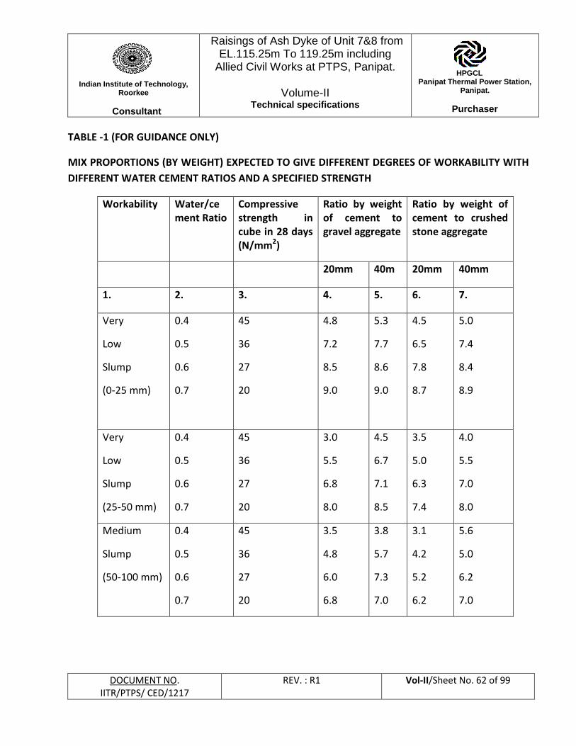
Indian Institute of Technology,
Roorkee
Consultant
Raisings of Ash Dyke of Unit 7&8 from EL.115.25m To 119.25m including
Allied Civil Works at PTPS, Panipat.
Volume-II Technical specifications
HPGCL Panipat Thermal Power Station,
Panipat.
Purchaser
DOCUMENT NO. IITR/PTPS/ CED/1217
REV. : R1 Vol-II/Sheet No. 62 of 99
TABLE -1 (FOR GUIDANCE ONLY)
MIX PROPORTIONS (BY WEIGHT) EXPECTED TO GIVE DIFFERENT DEGREES OF WORKABILITY WITH
DIFFERENT WATER CEMENT RATIOS AND A SPECIFIED STRENGTH
Workability Water/cement Ratio
Compressive strength in cube in 28 days (N/mm2)
Ratio by weight of cement to gravel aggregate
Ratio by weight of cement to crushed stone aggregate
20mm 40m 20mm 40mm
1. 2. 3. 4. 5. 6. 7.
Very
Low
Slump
(0-25 mm)
0.4
0.5
0.6
0.7
45
36
27
20
4.8
7.2
8.5
9.0
5.3
7.7
8.6
9.0
4.5
6.5
7.8
8.7
5.0
7.4
8.4
8.9
Very
Low
Slump
(25-50 mm)
0.4
0.5
0.6
0.7
45
36
27
20
3.0
5.5
6.8
8.0
4.5
6.7
7.1
8.5
3.5
5.0
6.3
7.4
4.0
5.5
7.0
8.0
Medium
Slump
(50-100 mm)
0.4
0.5
0.6
0.7
45
36
27
20
3.5
4.8
6.0
6.8
3.8
5.7
7.3
7.0
3.1
4.2
5.2
6.2
5.6
5.0
6.2
7.0
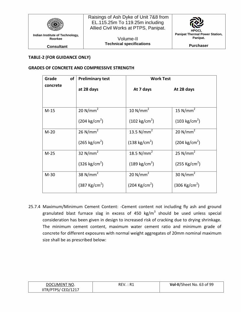
Indian Institute of Technology,
Roorkee
Consultant
Raisings of Ash Dyke of Unit 7&8 from EL.115.25m To 119.25m including
Allied Civil Works at PTPS, Panipat.
Volume-II Technical specifications
HPGCL Panipat Thermal Power Station,
Panipat.
Purchaser
DOCUMENT NO. IITR/PTPS/ CED/1217
REV. : R1 Vol-II/Sheet No. 63 of 99
TABLE-2 (FOR GUIDANCE ONLY)
GRADES OF CONCRETE AND COMPRESSIVE STRENGTH
Grade of
concrete
Preliminary test
at 28 days
Work Test
At 7 days At 28 days
M-15 20 N/mm2
(204 kg/cm2)
10 N/mm2
(102 kg/cm2)
15 N/mm2
(103 kg/cm2)
M-20 26 N/mm2
(265 kg/cm2)
13.5 N/mm2
(138 kg/cm2)
20 N/mm2
(204 kg/cm2)
M-25 32 N/mm2
(326 kg/cm2)
18.5 N/mm2
(189 kg/cm2)
25 N/mm2
(255 Kg/cm2)
M-30 38 N/mm2
(387 Kg/cm2)
20 N/mm2
(204 Kg/cm2)
30 N/mm2
(306 Kg/cm2)
25.7.4 Maximum/Minimum Cement Content: -Cement content not including fly ash and ground
granulated blast furnace slag in excess of 450 kg/m3 should be used unless special
consideration has been given in design to increased risk of cracking due to drying shrinkage.
The minimum cement content, maximum water cement ratio and minimum grade of
concrete for different exposures with normal weight aggregates of 20mm nominal maximum
size shall be as prescribed below:
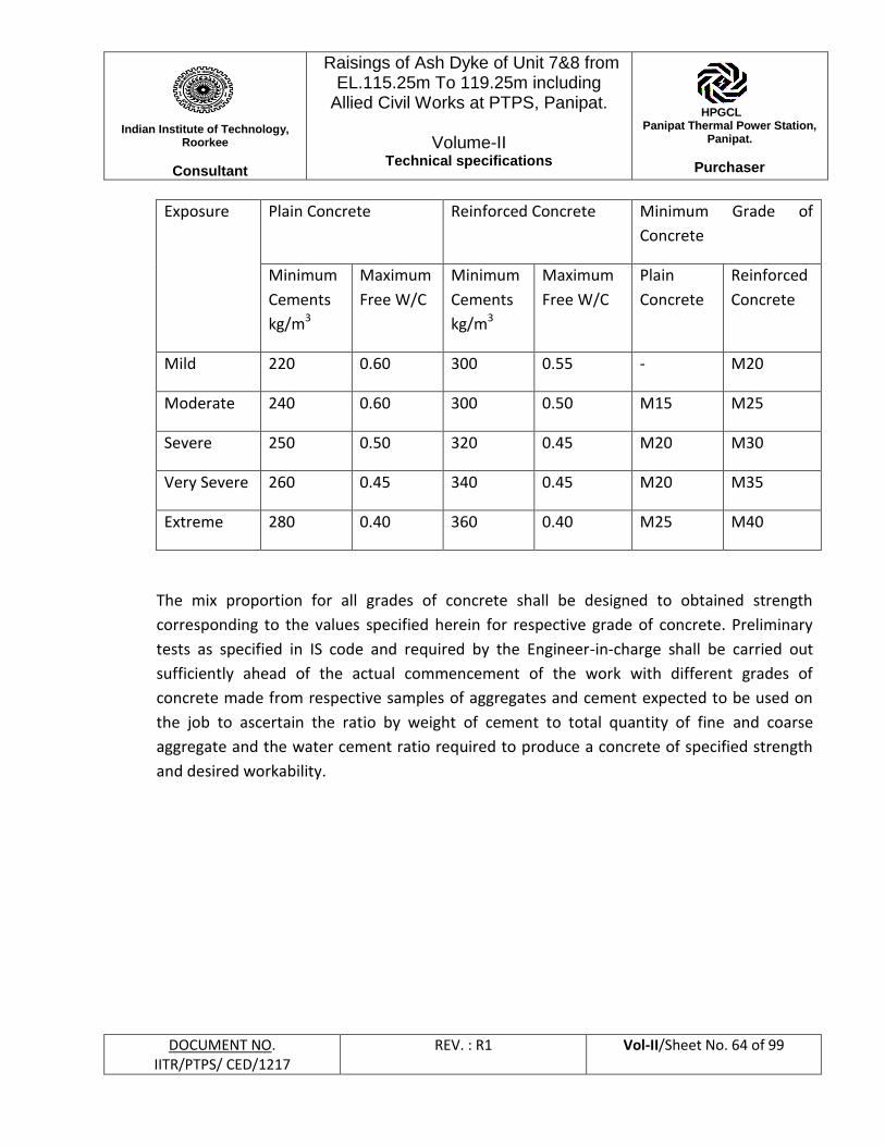
Indian Institute of Technology,
Roorkee
Consultant
Raisings of Ash Dyke of Unit 7&8 from EL.115.25m To 119.25m including
Allied Civil Works at PTPS, Panipat.
Volume-II Technical specifications
HPGCL Panipat Thermal Power Station,
Panipat.
Purchaser
DOCUMENT NO. IITR/PTPS/ CED/1217
REV. : R1 Vol-II/Sheet No. 64 of 99
Exposure Plain Concrete Reinforced Concrete Minimum Grade of
Concrete
Minimum
Cements
kg/m3
Maximum
Free W/C
Minimum
Cements
kg/m3
Maximum
Free W/C
Plain
Concrete
Reinforced
Concrete
Mild 220 0.60 300 0.55 - M20
Moderate 240 0.60 300 0.50 M15 M25
Severe 250 0.50 320 0.45 M20 M30
Very Severe 260 0.45 340 0.45 M20 M35
Extreme 280 0.40 360 0.40 M25 M40
The mix proportion for all grades of concrete shall be designed to obtained strength
corresponding to the values specified herein for respective grade of concrete. Preliminary
tests as specified in IS code and required by the Engineer-in-charge shall be carried out
sufficiently ahead of the actual commencement of the work with different grades of
concrete made from respective samples of aggregates and cement expected to be used on
the job to ascertain the ratio by weight of cement to total quantity of fine and coarse
aggregate and the water cement ratio required to produce a concrete of specified strength
and desired workability.
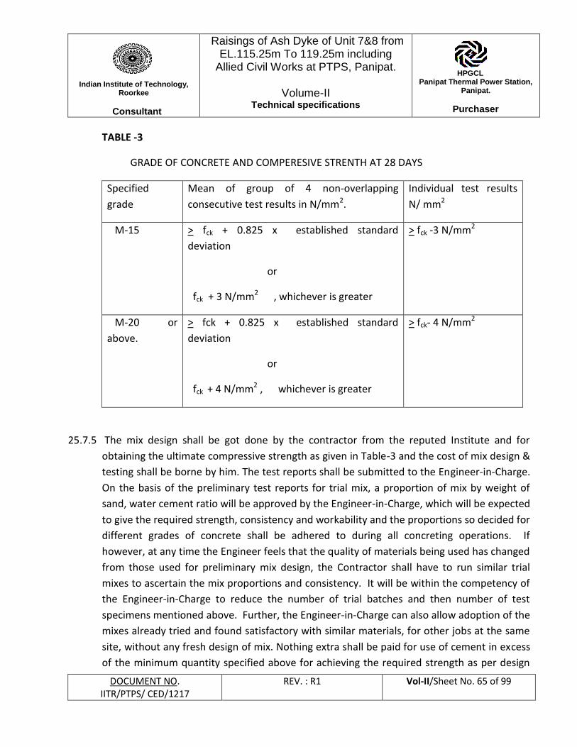
Indian Institute of Technology,
Roorkee
Consultant
Raisings of Ash Dyke of Unit 7&8 from EL.115.25m To 119.25m including
Allied Civil Works at PTPS, Panipat.
Volume-II Technical specifications
HPGCL Panipat Thermal Power Station,
Panipat.
Purchaser
DOCUMENT NO. IITR/PTPS/ CED/1217
REV. : R1 Vol-II/Sheet No. 65 of 99
TABLE -3
GRADE OF CONCRETE AND COMPERESIVE STRENTH AT 28 DAYS
Specified
grade
Mean of group of 4 non-overlapping
consecutive test results in N/mm2.
Individual test results
N/ mm2
M-15 > fck + 0.825 x established standard
deviation
or
fck + 3 N/mm2 , whichever is greater
> fck -3 N/mm2
M-20 or
above.
> fck + 0.825 x established standard
deviation
or
fck + 4 N/mm2 , whichever is greater
> fck- 4 N/mm2
25.7.5 The mix design shall be got done by the contractor from the reputed Institute and for
obtaining the ultimate compressive strength as given in Table-3 and the cost of mix design &
testing shall be borne by him. The test reports shall be submitted to the Engineer-in-Charge.
On the basis of the preliminary test reports for trial mix, a proportion of mix by weight of
sand, water cement ratio will be approved by the Engineer-in-Charge, which will be expected
to give the required strength, consistency and workability and the proportions so decided for
different grades of concrete shall be adhered to during all concreting operations. If
however, at any time the Engineer feels that the quality of materials being used has changed
from those used for preliminary mix design, the Contractor shall have to run similar trial
mixes to ascertain the mix proportions and consistency. It will be within the competency of
the Engineer-in-Charge to reduce the number of trial batches and then number of test
specimens mentioned above. Further, the Engineer-in-Charge can also allow adoption of the
mixes already tried and found satisfactory with similar materials, for other jobs at the same
site, without any fresh design of mix. Nothing extra shall be paid for use of cement in excess
of the minimum quantity specified above for achieving the required strength as per design
Indian Institute of Technology,
Roorkee
Consultant
Raisings of Ash Dyke of Unit 7&8 from EL.115.25m To 119.25m including
Allied Civil Works at PTPS, Panipat.
Volume-II Technical specifications
HPGCL Panipat Thermal Power Station,
Panipat.
Purchaser
DOCUMENT NO. IITR/PTPS/ CED/1217
REV. : R1 Vol-II/Sheet No. 66 of 99
mix for various grades of concrete even though the design mix is approved by the Engineer-
in Charge.
25.7.6 In designing, the mixes once approved must not be varied without prior approval of the
Engineer. Should, however, the Contractor anticipate any change in the quality of future
supply of materials than that has been used for preliminary mix design, he shall inform the
same to the Engineer and bring fresh samples sufficiently ahead to carry out fresh trial
mixes. The Engineer-in-Charge shall have access at all places and laboratory where design
mix is prepared.
25.7.7 Design mix will indicate the extent of variation in grade of aggregate, which can be allowed
by means of graphs and curves etc.
25.7.8 In designing, the mix proportions of concrete, the quantity of both cement and aggregate
shall be determined by weight. The Engineer-in-Charge may allow the quantity of aggregate
to be determined by equivalent volume basis after the relationship between the weight and
volume is well established by trial and the same shall be calibrated in tanks or weighed. All
measuring equipment shall be maintained in a clean and serviceable condition, and their
accuracy periodically checked.
25.7.9 To keep the water cement ratio to the designed value, allowance shall be made for the
moisture contents in both fine and coarse aggregates and determination of the same shall
be made as frequently as directed by the Engineer. The determination of moisture contents
shall be according to IS: 2386 (Part-III) (Latest edition).
25.8 Mixing and placing of concrete:
25.8.1 General:
Concrete shall not be placed in any unit of the work until after the forms, bracing, reinforcing
steel and other preparations for casting have been approved by the Engineer-in-Charge and
approval given to proceed with the casting.
25.8.2 Supervision:
No concrete shall be placed except in the presence of the Engineer-in-Charge or his
authorized representative. Concrete which is not placed in accordance with the
Indian Institute of Technology,
Roorkee
Consultant
Raisings of Ash Dyke of Unit 7&8 from EL.115.25m To 119.25m including
Allied Civil Works at PTPS, Panipat.
Volume-II Technical specifications
HPGCL Panipat Thermal Power Station,
Panipat.
Purchaser
DOCUMENT NO. IITR/PTPS/ CED/1217
REV. : R1 Vol-II/Sheet No. 67 of 99
specifications or which is of inferior quality as determined by the Engineer-in-Charge shall be
removed and replaced by the Contractor without any extra cost to the owner.
25.8.3 Mixing:
All concrete shall be mixed until there is a uniform distribution of materials and shall be
discharged completely before the mixer is recharged. Mixing shall be done in a mechanical
mixer and the type and size shall be subject to the approval of the Engineer-in-Charge. The
mixer shall be rotated at a speed recommended by the manufacturer and mixing shall be
continued for at least two minutes after all materials are in the drum. For batches larger
than 0.75 cum. mixing time shall be increased by 15 seconds for each additional 0.75 cum. or
fraction thereof. All concrete shall be discharged within 3 minutes after the introduction of
mixing water to the cement and aggregates or the introduction of cement to the aggregate
unless a different time is specified by the Engineer.
25.8.4 Before beginning a run of concrete all hardened concrete and foreign materials shall be
removed from the inner surfaces of mixing and conveying equipments. All conveyances,
buggies and barrows shall be thoroughly cleaned at frequent intervals during the placing of
concrete. Concrete shall be rapidly handled from the mixers to the place of final deposit and
shall not be delivered by spout or trough nor dumped into carriers with a free fall from the
mixer of more than one meter. Every possible precaution shall be taken to prevent
separation of loss of the ingredients while transporting the Concrete.
25.8.5 Each time the work stops, the mixer shall be thoroughly cleaned and when the next mixing
commences, the first batch shall have 10% additional cement at no extra cost to the owner
to allow for loss in the drum.
25.8.6 The workability of the concrete shall be checked at frequent intervals by slump test, where
facilities exist and if required by the Engineer-in-Charge, alternatively the compacting factor
test in accordance with IS: 1199 be carried out.
25.9 Transporting, Placing, compacting & curing:
25.9.1 Procedure for transporting, placing, compacting and curing shall conform to IS 456 (latest
edition). The placing of concrete shall be a continuous operation with no interruption in
excess of 30 minutes between the placing of continuous portions of concrete. Concrete shall
Indian Institute of Technology,
Roorkee
Consultant
Raisings of Ash Dyke of Unit 7&8 from EL.115.25m To 119.25m including
Allied Civil Works at PTPS, Panipat.
Volume-II Technical specifications
HPGCL Panipat Thermal Power Station,
Panipat.
Purchaser
DOCUMENT NO. IITR/PTPS/ CED/1217
REV. : R1 Vol-II/Sheet No. 68 of 99
be deposited in a manner to prevent displacing facilities, forms or reinforcement above the
level of the fresh concrete and the formation of seams or planes of weakness within the
sections. Each layer shall be plastic where a new layer is placed upon it. Concrete shall be
deposited close to its final position as practicable in order to prevent segregation. After
initial set of concrete the forms shall be jarred and no strain or vibrating equipment shall be
placed on the ends of projecting reinforcement.
25.9.2 Concrete shall not ordinarily be placed under water. In unavoidable cases, such concreting
shall be done only with, the specific approval of procedure and application by the Engineer.
Additional cement shall be to the extent of 10% and relevant clauses of IS: 456 (latest
edition) adhered to.
25.9.3 To secure maximum density and eliminate formation of all pockets, the concrete shall be
thoroughly vibrated and worked around all reinforcement, embedded facilities and into
corners of forms during and immediately after placing. Unless other methods are authorized
by the Engineer, mechanical vibrators shall be used for this purpose, the type and operation
of which is subjected to the approval of Engineer-in-charge. The extent of vibration shall be
through the entire depth of each new layer and several centimeters into layer below, with
vibration applied at the point of deposit and uniformly throughout the freshly placed
concrete, no farther apart than radius over which the vibration is visibly effective. Duration
of vibration shall be sufficient to accomplish through compaction and complete embedment
of reinforcement. Due to vibration the tendency for large aggregate to gravitate to lower
elevations shall not relieve the contractor from his responsibility of obtaining a uniform
density throughout the mass. Excess cement paste thus formed at the top of each layer shall
be removed before the succeeding layer is deposited. Hand tamping shall not be permitted.
Contractor shall provide proper equipment or methods for compaction of concrete at
corners or other similar area where conventional methods would not be adequate.
25.9.4 Retamping of concrete or mortar, which has partially hardened, shall not be permitted.
25.9.5 Before pouring the concrete in any work, the written approval of Engineer -in-charge shall be
obtained by the contractor.
Indian Institute of Technology,
Roorkee
Consultant
Raisings of Ash Dyke of Unit 7&8 from EL.115.25m To 119.25m including
Allied Civil Works at PTPS, Panipat.
Volume-II Technical specifications
HPGCL Panipat Thermal Power Station,
Panipat.
Purchaser
DOCUMENT NO. IITR/PTPS/ CED/1217
REV. : R1 Vol-II/Sheet No. 69 of 99
25.10 Construction joints:
25.10.1 The locations and details of construction joints not indicated on the drawing must be
approved by the Engineer-in-Charge before concrete is poured. . The construction joints
should be complying with IS 11817.
25.10.2 At the construction joint, a key and extra reinforcement will have to be provided. In
addition to this 12mm dia threaded nozzles of suitable length at spacing not more than
1.50m c/c will have to be provided along with construction joint. The top of the nozzle will
be kept closed by providing plugs. After pouring of concrete, the plug of the nozzles will be
removed & non-shrink water proof grouting compound mixed with neat cement slurry shall
be injected through the nozzles under pressure by pump to seal all pores cracks and
shrinkages. The nozzles shall be sealed after the injection operation. The pressure grouting
shall be got executed by specialists in this field.
25.10.3 The vertical construction joint in a RCC wall should be formed at pre-determined position
with a temporary particle board form work having suitable openings for the continuity of
reinforcement. This particleboard shall be removed after the concrete has set-in sufficiently
to retain its verticality and shape, before concreting is resumed in the adjacent portion.
25.10.4 At least two hours must lapse after depositing concrete in the columns or wall before
depositing in beams, girders or slabs supported thereon. Beams, girders, brackets and
haunches shall be considered as part of the floor system and shall be placed monolithic
therewith.
25.10.5 Construction joint between pile caps/equipment foundations etc. and floor shall be
provided with PVC water stops. Concurrence and approval of the Engineer will have to be
obtained before providing such joints.
25.10.6 When the work has to be resumed on a surface, which has hardened such surface shall be
roughened. It shall then be swept clean, thoroughly wetted and covered with a 15mm layer
of mortar composed of cement and sand in the same ratio as the cement and sand in the
concrete mix. This 15mm layer of mortar shall be freshly mixed & placed immediately
before the placing of the concrete.
25.10.7 Where the concrete has not fully hardened, all laitance shall be removed by dislodging of
particles of aggregate. The surface shall be thoroughly wetted and all free water removed.
Indian Institute of Technology,
Roorkee
Consultant
Raisings of Ash Dyke of Unit 7&8 from EL.115.25m To 119.25m including
Allied Civil Works at PTPS, Panipat.
Volume-II Technical specifications
HPGCL Panipat Thermal Power Station,
Panipat.
Purchaser
DOCUMENT NO. IITR/PTPS/ CED/1217
REV. : R1 Vol-II/Sheet No. 70 of 99
The surface shall then be coated with neat cement grout. The first layer of concrete to be
placed on this surface shall not exceed 150mm in thickness and shall be well rammed against
old work particular attention being paid to corners and close spots.
25.11 Inserts:
All anchors, anchor bolts, inserts, pipe, conduit, sleeves, floor angles, frames, nosing bolts
etc. and any other items that are required to be cast into the concrete shall be placed in
correct position before pouring. Extra care shall be taken during pouring operation to
maintain their locations. Block-outs and openings shall be kept wherever required.
25.12 Cleaning and finishing:
Except where a special finish is called for, all exposed concrete shall be finished as follows:
25.12.1 All fins and other projections shall be neatly chipped, rubbed down and made smooth, form
oil shall be entirely removed by stiff fiber brushes. The use of acid shall not be permitted.
All exposed corners shall be slightly rounded or chamfered. Air holes, cavities and similar
imperfections shall be first saturated with water and filled with a mortar mixture of the same
composition as that used in the concrete. After initial set of mortar, the surface shall be
rubbed down with burlap. A stucco coat shall be allowed to be applied to the surfaces. The
inside surfaces shall be ground smooth with carborundum stone.
25.12.2 Except where a separate finish is to be applied, or where a trowel finish is called for
horizontal concrete surfaces shall be floated.
25.12.3 Where a trowel finish is called for the surface shall be floated and steel troweled after
achieving initial set to prevent excess fine materials from working to the surface. The finish
shall be brought to a smooth dense surface free from defects and blemishes. No dry cement
or mixture of dry cement and sand shall be done after the concrete is so hard that no mortar
accumulates on the trowel and a ringing sound is produced as the trowel is drawn over the
surface.
25.13 Curing:
25.13.1 Unless otherwise specified all concrete shall be cured by keeping all exposed surfaces, edges
and corners continuously moist for at least seven days after being placed, by spraying,
ponding or covering with waterproof paper or moisture retaining fabric.
Indian Institute of Technology,
Roorkee
Consultant
Raisings of Ash Dyke of Unit 7&8 from EL.115.25m To 119.25m including
Allied Civil Works at PTPS, Panipat.
Volume-II Technical specifications
HPGCL Panipat Thermal Power Station,
Panipat.
Purchaser
DOCUMENT NO. IITR/PTPS/ CED/1217
REV. : R1 Vol-II/Sheet No. 71 of 99
25.13.2 Immediately after stripping of the forms, water shall be applied directly to the concrete
surfaces. The wetting down operations shall be continuous within the curing time specified.
25.13.3 As an alternative to continual wetting down of walls, the use of a sprayed-on membrane
may be substituted subject to approval by the Engineer-in-Charge.
25.14 Form work:
25.14.1 All details of formwork, placing, tying etc., shall be subject to the approval of the Engineer
and the Contractor shall submit drawings, when requested, showing details of form
construction. The Contractor shall be responsible for the adequacy of the formwork to
withstand the pressure of freshly placed concrete, or other loads imposed without failure,
movement or deflections of the components parts. Forms shall be true to the shape, lines
and dimensions of the concrete work.
25.14.1 For concrete surfaces that are exposed to view and for all other concrete surfaces that are to
be finished smooth, the lining of forms shall be of smooth non-absorbent lining material.
The type and conditions of such lining for forms shall be subject to the approval of the
Engineer-in-Charge. All edges of panels shall be square and straight in both directions and
all panels shall match perfectly in length, width and alignment as required.
25.14.2 All forms shall be sufficiently tight to prevent the loss of liquid from the concrete. All
rubbish particularly chipping, shaving and saw dust shall be removed from the interior of the
forms before the concrete is placed and the form work in contact with concrete shall be
cleaned and thoroughly wetted or treated with an approved composition to prevent
absorption of water from the concrete. Such composition shall be kept out of concrete with
reinforcement and shall be non-staining and not injurious to concrete.
25.14.3 Form lumber may be reused, provided that it is true, unwrapped, thoroughly clean and
without broken or damaged edges and equal in use in every respect to a new lumber. All
reform lumber shall have the contact surfaces recoiled or re-coated with an approved
composition prior to usage.
25.14.4 Contractor shall keep an accurate record of the date on which the concrete is cast for each
part of the work and the date upon which the formwork is removed.
Indian Institute of Technology,
Roorkee
Consultant
Raisings of Ash Dyke of Unit 7&8 from EL.115.25m To 119.25m including
Allied Civil Works at PTPS, Panipat.
Volume-II Technical specifications
HPGCL Panipat Thermal Power Station,
Panipat.
Purchaser
DOCUMENT NO. IITR/PTPS/ CED/1217
REV. : R1 Vol-II/Sheet No. 72 of 99
25.14.5 Removal of forms shall be in accordance with the following requirements:
i) No supporting forms should be removed suddenly in such a manner as to create
shock loading.
ii) In normal circumstances and where ordinary Portland cement is used, forms may
generally be removed after the expiry of the followings:
a) Walls, columns and vertical faces
of all structural members 24 to 48 hrs as may be decided by
Engineer
b) Slabs (props left under) 3 days
c) Beam soffits (props left under) 7 days
d) Removal of props under slabs:
Spanning up to 4.5m 7 days
Spanning over 4.5m 14 days
20.4.1 Removal of props under beams
and arches
Spanning up to 6m 14 days
Spanning over 6m 21 days
iii) For cement other than ordinary portland cement, the stripping time required as per
25.14.5 shall be suitably modified as per Engineer-in-Charge instruction.
25.14.7 Dimensional Tolerances:
The tolerance on the shapes, lines and diversion are given below:
( a) Sectional dimensions of column &Beam + 5mm
Indian Institute of Technology,
Roorkee
Consultant
Raisings of Ash Dyke of Unit 7&8 from EL.115.25m To 119.25m including
Allied Civil Works at PTPS, Panipat.
Volume-II Technical specifications
HPGCL Panipat Thermal Power Station,
Panipat.
Purchaser
DOCUMENT NO. IITR/PTPS/ CED/1217
REV. : R1 Vol-II/Sheet No. 73 of 99
(b) Plumb 3mm for every meter Max. 10 meter for
the concrete structure
(c) Levels & height + 5mm before any deflection has taken
(d)Unevenness of any surface + 3mm
(e) Length & breath +12mm
(f) Diagonals +1 5mm
25.15 Testing and acceptance criteria:
25.15.1 General:
The testing shall be carried out either at site laboratory to be set up by the contractor or at
any other NABL approved laboratory in accordance with the relevant Indian Standards. The
mould and material for cubes and cylinder shall be supplied by the Contractor, who shall also
arrange to transport the cubes/cylinders to the laboratory at his cost. Samples should be
taken in presence of the representative from the Purchaser and the Contractor. The cost of
testing shall be borne by the contractor.
25.15.2 Cement:
Cement shall be Ordinary Portland Cement of 33grade and 43grade conforming to IS: 269
and IS: 8112 respectively or Pozzolona Portland Cement and shall be obtained from
recognized supplier. The cement to be used shall be of the repute brand such as (i) Gujrat
Ambuja; (ii) L & T; (iii) J. K. Cement; (iv) Shree Cement; (v) Aditya Birla. Cement,(vi) ACC.
The test results in triplicate within three days (3) after completion of test.
25.15.3 Aggregates:
The aggregates shall be tested as and when required by the Engineer in accordance with IS:
2386 Part-I to VIII. The acceptance criteria of the samples tested shall be in accordance with
the requirements of relevant Indian Standards.
Indian Institute of Technology,
Roorkee
Consultant
Raisings of Ash Dyke of Unit 7&8 from EL.115.25m To 119.25m including
Allied Civil Works at PTPS, Panipat.
Volume-II Technical specifications
HPGCL Panipat Thermal Power Station,
Panipat.
Purchaser
DOCUMENT NO. IITR/PTPS/ CED/1217
REV. : R1 Vol-II/Sheet No. 74 of 99
25.15.4 Water:
Sampling and testing of water being used for concrete work as per IS: 3550 will be carried
out at regular intervals and wherever directed by the Engineer. The final acceptance criteria
shall be as per IS: 3025.
25.15.5 Admixtures:
Tests for establishing the various properties of any admixtures, which may be required to be
added, shall be carried out by the contractor free of charge to the owner.
25.15.6 Concrete:
25.15.6.1 The sampling of concrete, making the test specimen and testing procedure etc. shall be in
accordance with IS: 1199 and IS: 516. The size of the specimen shall be 15cm cube.
Normally only compression tests shall be performed but under special circumstances the
Engineer may require other tests to be performed in accordance with IS: 516.
25.15.6.2 Procedure laid down other wise in IS: 456 shall be followed for sampling and strength test
of concrete.
25.15.6.3 The acceptance criteria for the compressive strength shall be as per IS: 456 in subsequent.
25.15.6.4 Concrete of each grade shall be assessed separately.
25.15.6.5 Concrete shall be assessed daily for compliance.
25.15.6.6 Concrete is liable to be rejected if it is porous or honey combed it’s placing has been
interrupted without providing a proper construction joint; the reinforcement has been
displaced beyond the tolerances specified or construction tolerances have not been met.
However, the hardened concrete may be accepted after carrying out suitable remedial
measures to the satisfaction of the Engineer-in-Charge.
25.15.6.7 However, in exceptional circumstances, the Engineer-in-Charge may, at his discretion,
accept a concrete of lower strength than specified and which is otherwise acceptable
according to IS: 456.
25.15.6.8 Concrete work found unsuitable for acceptance shall have to be dismantled and
replacement is to be done, as per specification by the Contractor. No payment for the
dismantled concrete, the relevant formwork and reinforcement, embedded fixtures etc.
wasted in the dismantled portion shall be made. In the course of dismantling, if any
Indian Institute of Technology,
Roorkee
Consultant
Raisings of Ash Dyke of Unit 7&8 from EL.115.25m To 119.25m including
Allied Civil Works at PTPS, Panipat.
Volume-II Technical specifications
HPGCL Panipat Thermal Power Station,
Panipat.
Purchaser
DOCUMENT NO. IITR/PTPS/ CED/1217
REV. : R1 Vol-II/Sheet No. 75 of 99
damage is done to the embedded items or adjacent structures, the same shall be made
good, free of charge by the Contractor to the satisfaction of the Engineer-in-Charge.
25.15.6.9 The entire cost of load testing shall be borne by the Contractor. If a portion of the
Structure is found to be unacceptable, it shall be dismantled and replaced by a new
structure as per specification. The entire cost of dismantling and replacement and
restoration of the site shall be borne by the Contractor.
25.15.6.10 Payment for concrete which is normally unacceptable as per the criteria laid down in
above Para, but which has been accepted by the Engineer-in-Charge shall be made at a
reduced rate prorate to the strength obtained.
25.15.6.11 If, in the course of dismantling, any damage is done to the embedded items and/or other
adjacent structures, the same, shall be made good free of charge by the contractor to
the satisfaction of the Engineer-in-Charge.
25.16 Measurements and Payment:
25.16.1 The length, breadth and height of concrete shall be measured in metre correct to third
place of decimal. The quantity shall be calculated in cum. correct up to third place of
decimal. Deductions shall be made for all block outs and openings but not for embedments
and reinforcement.
25.16.2 Measurement of formwork shall be based on the contact area of concrete work from
dimensions shown on the drawings. The unit of measurement shall be sqm. Correct up to
second place of decimals.
Indian Institute of Technology,
Roorkee
Consultant
Raisings of Ash Dyke of Unit 7&8 from EL.115.25m To 119.25m including
Allied Civil Works at PTPS, Panipat.
Volume-II Technical specifications
HPGCL Panipat Thermal Power Station,
Panipat.
Purchaser
DOCUMENT NO. IITR/PTPS/ CED/1217
REV. : R1 Vol-II/Sheet No. 76 of 99
26.0 Reinforcement:
26.1 (a) Reinforcing steel shall be clean and free from loose mill scales, dust, loose rust and coats
of paints, oil, grease or other coating, which may impair or reduce bond. It shall conform to the
following IS specifications:
(i) Mild steel & medium tensile steel bars and hard drawn steel wire conforming to
Grade-I IS: 432
ii) High strength deformed steel bars conforming to IS: 1786
iii) Structural steel conforming to Gr. A of IS: 2062
iv) Thermo- mechanically treated bars (TMT Bars):
Reinforcement and structural steel of the main producers e.g. SAIL, TISCO and
Rastriya Ispat Nigam Ltd. Shall only be used.
(b) All steel reinforcements, including and above 6mm diameter shall necessarily be of
tested quality. The untested steel reinforcement shall not be allowed to be used.
(c) Reinforcement accessories shall be furnished by the contractor. Binding wire shall be
annealed iron wire quality not less than No. 16 SWG (1.65mm dia).
(d) Bar supports, chairs and bolsters (as approved by Engineer) shall be sufficiently strong to
support the steel properly.
26.2 Reinforcement steel required for all the works shall be in the scope of contractor.
26.3 The contractor shall furnish reinforcement accessories. Binding wire shall be annealed iron
wire quality not less than No. 16 SWG. (1.65mm dia). Bar support, chairs and bolsters as
required and as approved by the Engineer-in-Charge shall be sufficiently strong to support
the steel reinforcement properly. The cost of all reinforcement accessories shall be included
in the price bid.
26.4 Contractor shall fabricate and place reinforcement to shapes and dimensions, as per IS:
2502 "Code of Practice for Bending and Fixing Bars for concrete Reinforcement” and as
indicated in approved drawings of the contractor. The reinforcement shall be either plain or
deformed mild steel bars conforming to relevant I.S. specifications.
Indian Institute of Technology,
Roorkee
Consultant
Raisings of Ash Dyke of Unit 7&8 from EL.115.25m To 119.25m including
Allied Civil Works at PTPS, Panipat.
Volume-II Technical specifications
HPGCL Panipat Thermal Power Station,
Panipat.
Purchaser
DOCUMENT NO. IITR/PTPS/ CED/1217
REV. : R1 Vol-II/Sheet No. 77 of 99
26.5 The contractor shall prepare bar bending schedule on the basis of the approved drawings
marked released for construction and submit the same for approval to the Engineer-in-
Charge. No work shall be commenced without the approval of the Schedule.
26.6 The contractor shall adhere strictly to requirements for concrete cover over steel
reinforcement, protection of bars for bonding with future extensions, columns, ties, splices,
laps, spacer bars, temperature reinforcement, mesh reinforcement and other items in
connection with proper placing.
26.7 Reinforcement shall be placed accurately, tied or welded securely at intersections and
splices and held in position with spacers or other approved supports during concrete
placement. The wire ends should point away from surface.
26.8 Bending and Placing of Reinforcement:
26.8.1 Contractor shall fabricate and place reinforcement to shapes and dimensions, as indicated or
required to carry out intent of drawings and specifications. The reinforcement shall be
either plain or deformed mild steel bars conforming to relevant IS Specifications. The
reinforcements shall be bent and fixed in accordance with procedure specified in IS: 2502.
26.8.2 The Contractor shall prepare bar-bending schedule on the basis of the drawings marked,
released for construction and submit the same for approval of Engineer-in-Charge. No work
shall be commenced without the approval of the bar-bending schedule.
26.8.3 Any adjustments in reinforcement to suit field conditions and construction joints other than
shown on drawings shall be subject to approval of Engineer-in-Charge.
26.8.4 The Contractor shall adhere strictly to requirements for concrete cover over steel
reinforcement, protection of bars for bending with future extensions, columns, ties, splices,
laps, spacer bars, temperature reinforcement, mesh reinforcement and other items in
connection with proper placing.
Indian Institute of Technology,
Roorkee
Consultant
Raisings of Ash Dyke of Unit 7&8 from EL.115.25m To 119.25m including
Allied Civil Works at PTPS, Panipat.
Volume-II Technical specifications
HPGCL Panipat Thermal Power Station,
Panipat.
Purchaser
DOCUMENT NO. IITR/PTPS/ CED/1217
REV. : R1 Vol-II/Sheet No. 78 of 99
26.8.5 Reinforcement shall be placed accurately tied or welded securely at intersections and
splices and held in position with spacers or other approved supports during concrete
placement. Tie wire ends shall be pointed away from surface.
26.8.6 The Contractor shall furnish the reinforcement accessories. The wire shall be annealed iron
wire quality. Bar supports, chairs, spreaders, spacers and bolsters shall be sufficiently heavy
to support the reinforcement steel properly and shall be approved by the Engineer-in-
Charge. No separate payment shall be made on account of the binding wire.
26.9 Measurement and Payment:
Measurement of reinforcement steel shall be based on the calculated weight of steel
actually used in tones correct up to third place of decimal. No allowance shall be made for
wastage. No separate payment shall be made for binding wire. The chairs, lap lengths and
spacers as approved by the Engineer-in-Charge shall be measured as per the measurement
of reinforcement and shall be payable. The weight of reinforcement shall be calculated on
the basis of standard weights given in IS: 1786.
Any adjustments in reinforcement to suit field conditions and construction joints other than
shown on approved drawings shall be subject to approval of the Engineer-in-Charge.
Indian Institute of Technology,
Roorkee
Consultant
Raisings of Ash Dyke of Unit 7&8 from EL.115.25m To 119.25m including
Allied Civil Works at PTPS, Panipat.
Volume-II Technical specifications
HPGCL Panipat Thermal Power Station,
Panipat.
Purchaser
DOCUMENT NO. IITR/PTPS/ CED/1217
REV. : R1 Vol-II/Sheet No. 79 of 99
27.0 Miscellaneous Steel Supply and Erection:
27.1 Scope:
The specification covers the technical requirement for the supply, fabrication, erection and
installation of all miscellaneous steel by the contractor. Supply of miscellaneous steel shall
be in the scope of contractor. The extent and type of miscellaneous steel to be fabricated,
erected etc. shall be as per the detailed construction drawings.
Miscellaneous steel shall include items such as rolled sections like angles, joists, channels,
plates, etc. bolts set in concrete as for in pedestals, anchor blocks etc.
The above list is provided only as an illustration of the type of steel items to be considered as
miscellaneous steel and some items listed may not appear in the actual list. It shall also not
be construed as limiting to such items only.
27.2 Materials:
The steel shall conform to IS: 226 & IS: 2062 and bolts, nuts, electrodes etc. shall conform to
relevant Indian Standards. Supply of all structural steel shall be in the scope of contractor.
27.3 Fabrication:
27.3.1 The fabrication drawing along with bill of the materials for structural steel shall be
prepared by the contractor in accordance with the requirements as indicated in detailed
construction drawings and will be submitted to the purchaser/consultant for approval. After
approval of the fabrication drawing Contractor shall furnish electrodes at his own cost and
welding shall conform to IS: 816. The fabrication work shall generally conform to IS: 800.
27.3.2 The electrode for welding purpose shall confirm to IS 814 and shall be either of the following
make:
(i) Advani Oerlikon;
(ii) Indian Oxygen Ltd;
(iii) Phillips Industries Ltd. and their subsidiaries “PIECO”;
(iv) D & H Secheron Electrodes (P) Ltd.
Indian Institute of Technology,
Roorkee
Consultant
Raisings of Ash Dyke of Unit 7&8 from EL.115.25m To 119.25m including
Allied Civil Works at PTPS, Panipat.
Volume-II Technical specifications
HPGCL Panipat Thermal Power Station,
Panipat.
Purchaser
DOCUMENT NO. IITR/PTPS/ CED/1217
REV. : R1 Vol-II/Sheet No. 80 of 99
27.4 Erection:
The contractor shall erect all miscellaneous steel in accordance with the drawings and these
specifications including setting materials in concrete or grouting pieces in place, furnishing
all labour, materials, scaffolding, tools and services necessary for and incidental to its
transporting, unloading, storing, handling and erection. Contractor shall furnish welding
rods and arrange for field welding as required in accordance with IS: 816.
27.5 Installation & Safety Requirements:
27.5.1 During erection, contractor shall provide necessary temporary bracing or supports to ensure
proper installation of the materials. All material shall be erected in the true locations as
shown on the drawings with accurate plum and level. All installations shall be carried out
within the tolerances specified in the drawings.
27.5.2 All operations connected with welding and cutting, equipments shall confirm to the safety
requirements given in IS: 818.
27.5.3 Inspection and testing of the welds shall be as per IS: 822.
27.6 Painting:
All structural steel member surface shall be provided a shop coat of red oxide zinc chromate
primer touch up, a second coat of primer after erection and thereafter with three coats of
synthetic enamel paints of approved quality and shade confirming to relevant IS code.
27.7 Measurement and Payments:
27.7.1 The contractor along with fabrication drawings shall submit bill of quantities for approval.
The structural weight for various components shall be calculated on the basis of standard
steel table published by BIS in Kg correct up to second place of decimal. No payment for the
weight of bolts, nuts, washers, erection bolts and making fabrication drawings shall be
payable. The weight for payment purpose shall be considered as per the approved bill of
material.
Indian Institute of Technology,
Roorkee
Consultant
Raisings of Ash Dyke of Unit 7&8 from EL.115.25m To 119.25m including
Allied Civil Works at PTPS, Panipat.
Volume-II Technical specifications
HPGCL Panipat Thermal Power Station,
Panipat.
Purchaser
DOCUMENT NO. IITR/PTPS/ CED/1217
REV. : R1 Vol-II/Sheet No. 81 of 99
27.7.2 The rate to be quoted shall be inclusive of preparation of fabrication drawings, bill of
materials, supply of all materials, fabrication, erection, installation, painting, consumables,
labour, T & P etc specified above. The payment of structural steel shall be as under:
(i) 5% of quoted rates on submission and approval of fabrication drawings.
(ii) 70% of quoted rates on supply and fabrication of structural steel as per drawing.
(iii) 15% of quoted rates on erection, installation and welding of structural steel in
position as per drawing.
(iv) Balance 10% of quoted rates on painting and on completion of works in all respects.
Indian Institute of Technology,
Roorkee
Consultant
Raisings of Ash Dyke of Unit 7&8 from EL.115.25m To 119.25m including
Allied Civil Works at PTPS, Panipat.
Volume-II Technical specifications
HPGCL Panipat Thermal Power Station,
Panipat.
Purchaser
DOCUMENT NO. IITR/PTPS/ CED/1217
REV. : R1 Vol-II/Sheet No. 82 of 99
28.0 Plastering:
28.1 Scope of Work
The scope of work includes the plastering of specified thickness on RR Stone masonry/ Brick
masonary works at ash pond area with cement sand mortar in single / double coats as
specified in drawing including all labour, material, T & P, required for successful completion
of the work.
28.2 Material
(a) Ordinary Portland cement shall be of 33 Grade or Grade 43 Grade conforming to IS:
269 (Latest) and IS: 8112 (Latest) respectively.
(b) The sand of plastering shall conform to IS: 1542-1977.
(c) Water proofing compound of approved make @ 2% of quantity of cement / as
recommended by the manufacturer shall be used.
(d) The ingredients for mortar shall be mixed in specified proportion by volume (1 Cement: 4
Fine sand).
28.3 Preparation of Surface
The obtain satisfactory bond between the masonry and the plaster, the joints of RR Stone
masonry/ brick masonry shall be raked out with a hook to a depth of about 20 mm if not
done earlier. The wall shall be damped evenly before applying the plaster.
28.4 Laying
After the surface has been prepared dabs or reference marks of mortar shall be fixed to
ensure that the plastered surface shall be truly plain and that the plaster coat shall have the
required thickness. Cement plaster 20 mm average thick shall be applied in two coats. The
thickness of under coat shall be 13mm (app.) and that of finishing coat shall be 7mm (app.).
Cement plaster 15 mm thick shall be applied in single layer. The mortar of specified mix shall
be applied uniformly between the mortar dabs and finished off with a wooden straight edge
reaching across the dabs and shall be finished of with dasterar wooden float.
Indian Institute of Technology,
Roorkee
Consultant
Raisings of Ash Dyke of Unit 7&8 from EL.115.25m To 119.25m including
Allied Civil Works at PTPS, Panipat.
Volume-II Technical specifications
HPGCL Panipat Thermal Power Station,
Panipat.
Purchaser
DOCUMENT NO. IITR/PTPS/ CED/1217
REV. : R1 Vol-II/Sheet No. 83 of 99
After preparing the surface and laying the dabs as detailed above, the under coat shall be
applied uniformly thick by laying on or throwing from the trowel. The mortar shall be well
pressed so that the raked joints are properly filled. The surface shall be left rough and
furrowed 2 mm deep with a scratching tool diagonally both ways to form a key for the
finishing coat so as to have a proper bondage. The surface shall be kept wet till the finishing
coat is applied. The finishing coat shall be started within 48 hrs. of the first coat applied.
For the finishing coat the mortar shall be applied uniformly between the mortar dabs and
finished off with a wooden straight edge reaching across the dabs and shall be finished off
with wooden float.
28.5 Curing
Curing shall be started as soon as the plaster has hardened sufficiently not to be damaged
when watered.
28.6 Defects
Any cracks in the plaster, or parts which sound hollow when tapped or are found to be soft
or otherwise defective after the plaster has dried, shall be cut out in rectangle or square and
re-plastered by the contractor as directed by Engineer-in-Charge.
28.7 Measurement & Payment
Length and breadth shall be measured in meter correct to the second place of decimal and
its area shall be calculated in square meters correct to second place of decimal. The
operations for plaster includes plastering of RR stone masonry surface with the specified
mortar, preparing, cleaning and watering the surface to be plastered, provision for erection
and removal of scaffolding / staging for all leads and lifts and provision of all T & P labour,
material and all such incidental items required for the completion of the work.
Indian Institute of Technology,
Roorkee
Consultant
Raisings of Ash Dyke of Unit 7&8 from EL.115.25m To 119.25m including
Allied Civil Works at PTPS, Panipat.
Volume-II Technical specifications
HPGCL Panipat Thermal Power Station,
Panipat.
Purchaser
DOCUMENT NO. IITR/PTPS/ CED/1217
REV. : R1 Vol-II/Sheet No. 84 of 99
29.0 R.C.C. Pipes of Class ‘NP3’:
29.1 Scope:
The work shall comprise of providing all material/T&P/ labour, etc. and doing all operations
necessary to complete for supply and laying R.C.C. non-pressure pipes NP3 type in
accordance with drawings and specifications.
29.2 Material:
Pipes shall conform to IS: 458. They shall be manufactured by centrifugal (or spun) process.
All pipes shall be true to shape, strength, perfectly sound and free from cracks and flows.
The external and internal surface of the pipes shall be smooth and hard. The pipes shall be
free from defects resulting from imperfect grading or the aggregate mixing or molding.
Concrete used for the manufacture of RCC pipes and collars shall not be leaner than M-15.
The maximum size of aggregate should not exceed 1/3rd of the thickness of the pipe or 20
mm whichever is smaller. The reinforcement shall extend throughout the length of the pipe.
The circumferential and longitudinal reinforcements shall be adequate to withstand the
specified hydrostatic pressure and further bending stresses due to the weight of water when
running full across a span equal to the length of pipe plus three times its own weight. These
will conform to provisions laid down in IS: 458.
29.3 Laying of Pipes:
Loading, transporting and unloading of concrete pipes shall be done with care. Handling
shall be such as to avoid impact. Gradual unloading by inclined plane or by chain block is
recommended. All pipe sections and connections shall be inspected carefully before being
laid. Broken or defective pipes of connections shall not be used.
Pipes shall be lowered into the trenches carefully. Mechanical appliances may be used.
Pipes shall be laid true to line and grade as specified. Laying of pipes shall proceed up-grade
of a slope. The socket end shall face upstream.
In cases where the natural foundation is inadequate, the pipe shall be laid either in concrete
cradle supported on proper foundations or on any other suitably designed structure. If a
concrete cradle bedding is used the depth of concrete below the bottom of the pipe shall be
at least ¼ of the internal dia. of the pipe subject to the minimum of 10cm and a maximum
Indian Institute of Technology,
Roorkee
Consultant
Raisings of Ash Dyke of Unit 7&8 from EL.115.25m To 119.25m including
Allied Civil Works at PTPS, Panipat.
Volume-II Technical specifications
HPGCL Panipat Thermal Power Station,
Panipat.
Purchaser
DOCUMENT NO. IITR/PTPS/ CED/1217
REV. : R1 Vol-II/Sheet No. 85 of 99
30cm. The concrete shall extend up the sides of the pipe at least to a distance of ¼ of the
outside diameter of pipes 300 mm and over in dia. The pipe shall be laid in this concrete
bedding before the concrete has set. Pipes laid in trenches in earth shall be bedded evenly
and firmly and as far up the haunches of the pipe as to safely transmit the load expected
from the backfill through the pipe to the bed. This shall be done either by excavating the
bottom of the trench to fit the curve of the pipe to form an even bed. Necessary provision
shall be made for joints wherever required.
When the pipes are laid completely above the ground, the foundations shall be made even
and sufficiently compacted to support the pipeline without any material settlement.
Alternatively, the pipeline shall be supported on rigid foundations at intervals. Suitable
arrangements shall be made to retain the pipeline in the proper alignment, such as by
shaping the top of the supports to fit the lower part of the pipe. The distance between the
supports shall in no case exceed the length of the pipe. The pipe shall be supported as far
as possible close to joints. In no case shall the joint come in the centre of the span. Care
shall be taken to see that superimposed loads greater than the total load equivalent to the
weight of the pipe when running full shall not be permitted.
29.4 Jointing of Pipes:
As described in the working drawings, the specific joint will be provided. Some of the
typical joints are described below:
29.4.1 Collar Joint (Rigid):
The two adjoining pipes shall be butted against each other adjusted in correct position. The
collar shall then be slipped over the joint, covering equally both the pipes. The annular
space shall be filled with stiff mixture of cement mortar 1:2 (1 cement: 2 fine sand), which
shall be rammed with caulking tool. After a day’s work any extraneous materials shall be
removed from the inside of the pipe and the newly made joint shall be cured.
29.4.2 Flush Joint (Internal):
This joint is generally used for culvert pipe of 60 cm dia. and over. The ends of the pipe are
specially shaped to form a self-centering joint with an internal jointing space 1.3 cm wide the
finished joint is flush with both inside and outside with the pipe wall. The jointing space is
Indian Institute of Technology,
Roorkee
Consultant
Raisings of Ash Dyke of Unit 7&8 from EL.115.25m To 119.25m including
Allied Civil Works at PTPS, Panipat.
Volume-II Technical specifications
HPGCL Panipat Thermal Power Station,
Panipat.
Purchaser
DOCUMENT NO. IITR/PTPS/ CED/1217
REV. : R1 Vol-II/Sheet No. 86 of 99
filled with cement mortar 1:2 (1 cement: 2 fine sand) mixed sufficiently dry to remain in
position when forced with a trowel or hammer.
After a day’s work any extraneous material shall be removed from the inside of the pipe and
the newly made joint shall be cured.
29.4.3 Flush Joint (External):
This joint is suitable for pipes which are too small for jointing from inside. This joint is
composed of specially shaped pipe ends. Each end shall be butted against each other and
adjusted in correct position. The jointing space shall then be filled with cement mortar 1:2
(1 cement : 2 fine sand) sufficiently dry and finished off flush. Great care shall be taken to
ensure that the projecting ends are not damaged as no repairs can be readily affected from
inside the pipe.
29.5 Opening to Traffic:
No traffic shall be permitted to cross the pipeline unless concrete around the pipe is
completed and cured for ten days.
29.6 Measurement and Payment:
The measurement of different type of pipe shall be made in running meter correct up to
second place of decimal. The rate shall be inclusive of supplying, laying and jointing etc.
However, the concrete bedding, if required, shall be paid as per the item of concreting. The
other items shall be measured as per the item specified in the schedule. The quoted price
shall also include supply of materials including special pieces, relevant erection with relevant
sealing, hangers of any kind, length and size as required for fastening the single piece as well
as any masonry work for embedding the hangers and testing of joints by relevant methods.
Indian Institute of Technology,
Roorkee
Consultant
Raisings of Ash Dyke of Unit 7&8 from EL.115.25m To 119.25m including
Allied Civil Works at PTPS, Panipat.
Volume-II Technical specifications
HPGCL Panipat Thermal Power Station,
Panipat.
Purchaser
DOCUMENT NO. IITR/PTPS/ CED/1217
REV. : R1 Vol-II/Sheet No. 87 of 99
30.0 Metallic Roads:
30.1 Preparation of Sub-grade
30.1.1 Earthen Sub-grade
The surface of the formation for a width equal to that of sub-base course shall be first cut to
a depth below the proposed finished level, equal to the combined depth of Sub-base and
wearing course, due allowance being made for compaction, It shall then be cleaned of all
foreign substances. Any ruts of soft yielding places that appear due to improper drainage
conditions, traffic hauling and other cause shall be corrected and the sub-grade dressed off
parallel to the finished profile. The sub-grade shall then be sprinkled with water and rolled
with minimum of 5 numbers of passes of 8-10 tonne smooth wheeled roller till the soil is
evenly and densely compacted. All undulations in the surface that might develop due to
rolling shall be made good with earth or quarry spoils as the case may be, and sub-grade
rolled.
30.2 Sub-base
30.2.1 Material
Suitable cool pick stone (reject coal boulders) available in Panipat Thermal Plant area shall
be used in 200m m thick sub base course of road. The cool pick stone shall be issued free of
cost to the contractor on as is where is bases and contractor shall arrange for breaking them
further in the require sizes. Loading, Unloading, handling and transportation of the same
from Power Plant to work site shall be at contractors own cost and deemed to be covered in
his quoted unit rate for sub base course of road specified in the price schedule.
30.2.2 Immediately prior to laying of sub-base, the sub-grade already finished shall be prepared by
removing all vegetation and other extraneous matters, lightly sprinkled with water, if
necessary and rolled with one pass of 8-10 tonne smooth wheeled roller.
30.2.3 Sub-base shall be of 200mm compacted thickness to be laid in two layer layers of 100mm
thick each.
30.2.4 The coarse aggregate shall be spread uniformly upon the prepared base in such quantities
that the thickness of compacted layer is 100mm. The spreading shall be done from stack
Indian Institute of Technology,
Roorkee
Consultant
Raisings of Ash Dyke of Unit 7&8 from EL.115.25m To 119.25m including
Allied Civil Works at PTPS, Panipat.
Volume-II Technical specifications
HPGCL Panipat Thermal Power Station,
Panipat.
Purchaser
DOCUMENT NO. IITR/PTPS/ CED/1217
REV. : R1 Vol-II/Sheet No. 88 of 99
piles along the sides of the roadway and not directly from vehicles. In no time shall the
aggregate be dumped in heaps directly on the surface prepared to receive the aggregate
nor shall hauling over uncompacted or partially compacted base is permitted. Surface of the
aggregate spread shall be carefully checked with templates and all high or low spots
remedied by removing or adding aggregate as may be required. No segregation of large or
fine particles shall be allowed and the coarse aggregate, as spread shall be of uniform
gradation with no pockets of fine material. The coarse shall be spread more than 3 days in
advance of the subsequent construction operation.
30.2.5 Immediately following the spreading of the coarse aggregates, rolling shall be started with
three-wheeled power rollers of 8 to 10 tonne capacity or tandom or vibratory rollers of
approved type. Expect on super-elevated portions where rolling shall proceed from inner
edge to the outer, rolling shall begin from edges gradually progressing towards the centre.
First the edge/edges shall be compacted with roller running forward and backward. The
roller shall then move inwards parallel to the centre line of the road, in successive passes
uniformly overlapping preceding tracks by at least one half width. Rolling shall be
discontinued when aggregates are partially compacted with sufficient void space in them to
permit application of screenings. During rolling light sprinkling of water may be done if
necessary. Rolling shall not be done when sub-grade is soft or yielding or when sub-grade is
soft or yielding or when it causes a wave likes motion in sub-grade or sub-base course.
30.2.6 After coarse aggregate has been rolled, screenings of above material (Coal pick stones) to
completely fill the voids shall be applied gradually on the surface. These shall not be damp or
wet at the time of application. Dry rolling shall be done while screenings are being spread so
that vibrations of the roller cause to settle into the voids of the coarse aggregate. The
screening shall be applied at a slow and uniform rate (in three or more applications) so as to
ensure filling of all voids. This shall be accompanied by dry rolling and brooming with
mechanical broom, hand brooms or gunny bags. These operations shall continue until no
more screenings can be forced into voids of the coarse aggregate. The applications of
screenings shall be carried out in only lengths of roads, which could be completed within one
day’s operation. After screenings have been applied, the surface shall be copiously sprinkled
with water, swept and rolled. Hand brooms shall be used to sweep wet screenings into voids
and to distribute them evenly. The sprinkling, sweeping and rolling operations shall be
continued with additional screenings applied, if necessary, until the coarse aggregate had
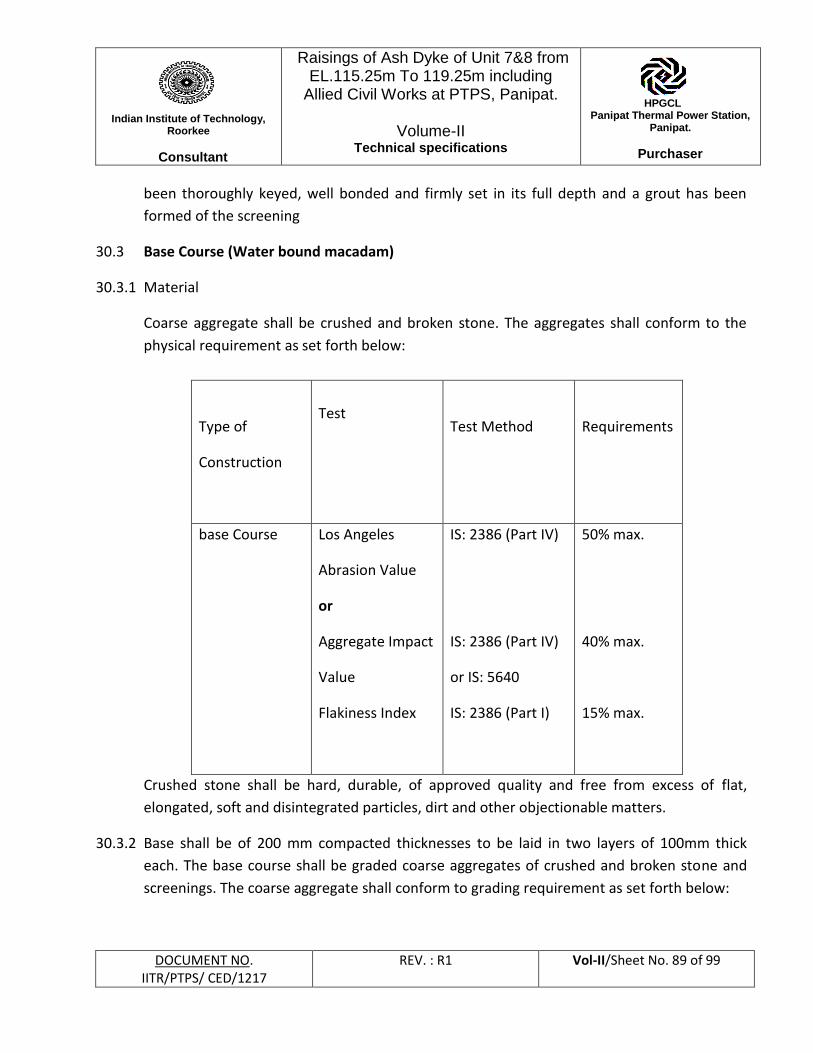
Indian Institute of Technology,
Roorkee
Consultant
Raisings of Ash Dyke of Unit 7&8 from EL.115.25m To 119.25m including
Allied Civil Works at PTPS, Panipat.
Volume-II Technical specifications
HPGCL Panipat Thermal Power Station,
Panipat.
Purchaser
DOCUMENT NO. IITR/PTPS/ CED/1217
REV. : R1 Vol-II/Sheet No. 89 of 99
been thoroughly keyed, well bonded and firmly set in its full depth and a grout has been
formed of the screening
30.3 Base Course (Water bound macadam)
30.3.1 Material
Coarse aggregate shall be crushed and broken stone. The aggregates shall conform to the
physical requirement as set forth below:
Type of
Construction
Test
Test Method
Requirements
base Course Los Angeles
Abrasion Value
or
Aggregate Impact
Value
Flakiness Index
IS: 2386 (Part IV)
IS: 2386 (Part IV)
or IS: 5640
IS: 2386 (Part I)
50% max.
40% max.
15% max.
Crushed stone shall be hard, durable, of approved quality and free from excess of flat,
elongated, soft and disintegrated particles, dirt and other objectionable matters.
30.3.2 Base shall be of 200 mm compacted thicknesses to be laid in two layers of 100mm thick
each. The base course shall be graded coarse aggregates of crushed and broken stone and
screenings. The coarse aggregate shall conform to grading requirement as set forth below:
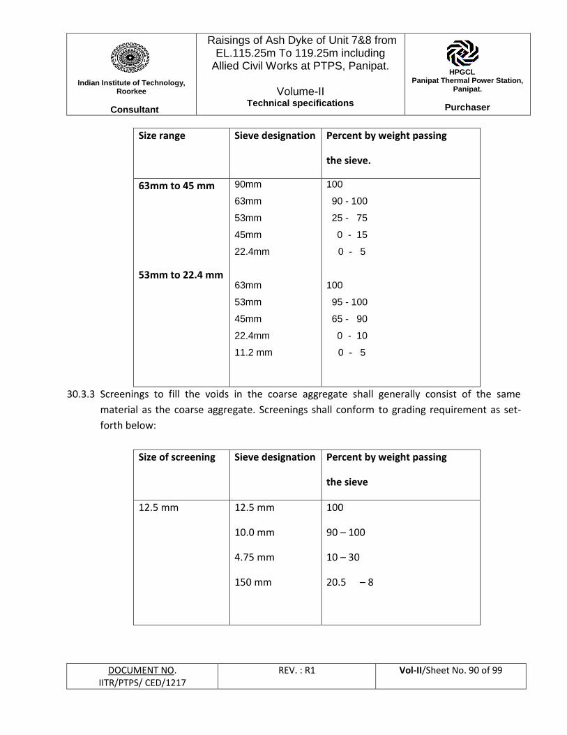
Indian Institute of Technology,
Roorkee
Consultant
Raisings of Ash Dyke of Unit 7&8 from EL.115.25m To 119.25m including
Allied Civil Works at PTPS, Panipat.
Volume-II Technical specifications
HPGCL Panipat Thermal Power Station,
Panipat.
Purchaser
DOCUMENT NO. IITR/PTPS/ CED/1217
REV. : R1 Vol-II/Sheet No. 90 of 99
Size range
Sieve designation Percent by weight passing
the sieve.
63mm to 45 mm
53mm to 22.4 mm
90mm
63mm
53mm
45mm
22.4mm
63mm
53mm
45mm
22.4mm
11.2 mm
100
90 - 100
25 - 75
0 - 15
0 - 5
100
95 - 100
65 - 90
0 - 10
0 - 5
30.3.3 Screenings to fill the voids in the coarse aggregate shall generally consist of the same
material as the coarse aggregate. Screenings shall conform to grading requirement as set-
forth below:
Size of screening Sieve designation Percent by weight passing
the sieve
12.5 mm 12.5 mm
10.0 mm
4.75 mm
150 mm
100
90 – 100
10 – 30
20.5 – 8
Indian Institute of Technology,
Roorkee
Consultant
Raisings of Ash Dyke of Unit 7&8 from EL.115.25m To 119.25m including
Allied Civil Works at PTPS, Panipat.
Volume-II Technical specifications
HPGCL Panipat Thermal Power Station,
Panipat.
Purchaser
DOCUMENT NO. IITR/PTPS/ CED/1217
REV. : R1 Vol-II/Sheet No. 91 of 99
30.3.4 Immediately prior to laying of sub-base, the sub-grade already finished shall be prepared by
removing all vegetation and other extraneous matters, lightly sprinkled with water, if
necessary and rolled with one pass of 8-10 tonne smooth wheeled roller.
30.3.5 The coarse aggregate shall be spread uniformly upon the prepared base in such quantities
that the thickness of compacted layer is 100mm. The spreading shall be done from stack
piles along the sides of the roadway and not directly from vehicles. In no time shall the
aggregate be dumped in heaps directly on the surface prepared to receive the aggregate nor
shall hauling over uncompacted or partially compacted base is permitted. Surface of the
aggregate spread shall be carefully checked with templates and all high or low spots
remedied by removing or adding aggregate as may be required. No segregation of large or
fine particles shall be allowed and the coarse aggregate, as spread shall be of uniform
gradation with no pockets of fine material. The coarse shall be spread more than 3 days in
advance of the subsequent construction operation.
30.3.6 Immediately following the spreading of the coarse aggregates, rolling shall be started with
three-wheeled power rollers of 8 to 10 tonne capacity or tandom or vibratory rollers of
approved type. Expect on super-elevated portions where rolling shall proceed from inner
edge to the outer, rolling shall begin from edges gradually progressing towards the centre.
First the edge/edges shall be compacted with roller running forward and backward. The
roller shall then move inwards parallel to the centre line of the road, in successive passes
uniformly overlapping preceding tracks by at least one half width. Rolling shall be
discontinued when aggregates are partially compacted with sufficient void space in them to
permit application of screenings. During rolling light sprinkling of water may be done if
necessary. Rolling shall not be done when sub-grade is soft or yielding or when sub-grade is
soft or yielding or when it causes a wave likes motion in sub-grade or sub-base course.
30.3.7 The rolled surface shall be checked transversely and longitudinally with templates and any
irregularities corrected by loosening the surface, adding or removing necessary amounts of
aggregate and re-rolling until the entire surface conforms to the desired camber and grade.
In no case, shall the use of screenings be permitted to make up depressions.
30.3.8 After coarse aggregate has been rolled, screenings to completely fill the voids shall be
applied gradually on the surface. These shall not be damp or wet at the time of application.
Dry rolling shall be done while screenings are being spread so that vibrations of the roller
Indian Institute of Technology,
Roorkee
Consultant
Raisings of Ash Dyke of Unit 7&8 from EL.115.25m To 119.25m including
Allied Civil Works at PTPS, Panipat.
Volume-II Technical specifications
HPGCL Panipat Thermal Power Station,
Panipat.
Purchaser
DOCUMENT NO. IITR/PTPS/ CED/1217
REV. : R1 Vol-II/Sheet No. 92 of 99
cause to settle into the voids of the coarse aggregate. The screening shall be applied at a
slow and uniform rate (in three or more applications) so as to ensure filling of all voids. This
shall be accompanied by dry rolling and brooming with mechanical broom, hand brooms or
gunny bags. These operations shall continue until no more screenings can be forced into
voids of the coarse aggregate. The applications of screenings shall be carried out in only
lengths of roads, which could be completed within one day’s operation. After screenings
have been applied, the surface shall be copiously sprinkled with water, swept and rolled.
Hand brooms shall be used to sweep wet screenings into voids and to distribute them
evenly. The sprinkling, sweeping and rolling operations shall be continued with additional
screenings applied, if necessary, until the coarse aggregate had been thoroughly keyed, well
bonded and firmly set in its full depth and a grout has been formed of the screenings.
30.3.9 Second layer of 100mm thick sub base shall be laid as per procedure and manner specified
above.
30.3.10 The binding material used shall consist of suitable material approved by Engineer having a
plasticity index value less than 6 as determined in accordance with IS: 2770 (Part – V).
Application of binding material will not be necessary, when the screenings used are of
crushable type such as morrum or gravel.
30.3.11 Water bound macadam base course shall be of a consolidated thickness of 100mm laid in
one layer.
30.3.12 Construction operation for above bound macadam base course shall be similar to that
detailed herein above for sub-base course.
30.3.13 Binder material as defined in Clause 4.3.2 shall be applied successively in two or more thin
layers at a slow and uniform rate. After each application, the surface shall be copiously
sprinkled with water, the resulting slurry swept in with hand broom or mechanical brooms
to fill the voids properly and rolled during which, water shall be applied to the wheels of the
rollers. if necessary, to wash down the binding material sticking to them. These operations
shall continue until the resulting slurry of the filling of voids from a wave ahead of the
wheels of the moving roller.
Indian Institute of Technology,
Roorkee
Consultant
Raisings of Ash Dyke of Unit 7&8 from EL.115.25m To 119.25m including
Allied Civil Works at PTPS, Panipat.
Volume-II Technical specifications
HPGCL Panipat Thermal Power Station,
Panipat.
Purchaser
DOCUMENT NO. IITR/PTPS/ CED/1217
REV. : R1 Vol-II/Sheet No. 93 of 99
30.3.14 After the final compaction of WBM course, the same shall be allowed to dry over night. Next
morning, hungry spots shall be filled with screenings and binding materials as directed and
lightly sprinkled with water and if necessary, rolled. No traffic shall be allowed on the road
until the macadam surface has set for at least 4 days. Road shall be kept watered so that it
remains in a damp condition under traffic for at least 14 days.
30.3.15 Rectification: Where the surface irregularity fall outside the specified tolerances the
contractor shall be liable to rectify it to the satisfaction of Engineer – in – Charge by adding
fresh material and recompacting to specifications where the surface is low. Where the
surface is high the full depth of the layer shall be removed and replaced with fresh material
and compacted to specifications.
30.3.16 Measurement
Formation of sub-grade, sub-base and water bound macadam base shall be measured as
finished work in position in cubic meters correct up to three places of decimal.
The longitudinal profile shall be checked during execution with a three meter long
straight edge and graduated wedge at the middle of each traffic lane along the road.
Similarly the transverse profile shall be checked with adjustable templates at intervals of 10
meters
31. Toe Drains:
Brick masonry toe drains shall be provided throughout the length of dyke at the downstream
toe of Ash Dyke as indicated in the drawings and as per the details shown therein.
Indian Institute of Technology,
Roorkee
Consultant
Raisings of Ash Dyke of Unit 7&8 from EL.115.25m To 119.25m including
Allied Civil Works at PTPS, Panipat.
Volume-II Technical specifications
HPGCL Panipat Thermal Power Station,
Panipat.
Purchaser
DOCUMENT NO. IITR/PTPS/ CED/1217
REV. : R1 Vol-II/Sheet No. 94 of 99
32. HIGH DENSITY POLYTHYLENE PIPES (HDPE)
32.1 Scope:- The scope of work includes providing and laying of HDPE pipes for drainage of
water from the blanket filter of Ash Dyke including all labour, material T & P,
supervision etc.
32.2 Material:- HDPE pipes shall conform to IS: 4984:1995 (latest edition) having pressure
rating of pipes PN 6 (Maximum permissible working pressure 0.60 MPa), and PE 80
Material Grade. The upper half portion of the pipe shall be perforated as per drawings
& direction of Engineer- In- charge. The material shall be got approved from the
purchaser/ consultant before laying at site. The necessary test results of the material
shall be supplied by the contractor. Material shall be ISI marked.
32.3 Laying:- HDPE pipes shall be laid on the firm ground as per drawing. Pipes shall be
wrapped with non-woven geotextile before laying in position.
32.4 Measurement:- Pipe laid at site shall be measured correct upto a centimetre and paid
as per contractual rates.
Indian Institute of Technology,
Roorkee
Consultant
Raisings of Ash Dyke of Unit 7&8 from EL.115.25m To 119.25m including
Allied Civil Works at PTPS, Panipat.
Volume-II Technical specifications
HPGCL Panipat Thermal Power Station,
Panipat.
Purchaser
DOCUMENT NO. IITR/PTPS/ CED/1217
REV. : R1 Vol-II/Sheet No. 95 of 99
ANNEXURE - I
Raisings of Ash Dyke of Unit 7&8 from EL.115.25m To 119.25m including Allied Civil Works
at PTPS, Panipat
Ash/Earthwork Inspector's daily Report
Date………………………
Shift……………………………
Weather……………………………..
Name of Contractor's Supervisor……………………………………………
Type of Roller Equipment used……………………………………………..
Weight of Roller……………………………………………………………..
(A) EXCAVATION
1. Type of Excavator
2. Depth of Cut
3. Type of Soil
4. Borrow Pit Location
5. Whether Water added at Borrow Pit
6. Moisture Content (%)
(B) FILL CONDITIONS
1. Location of Fill
2. Elevation
3. Whether Water added at the Fill
4. Moisture Condition before Rolling
5. Roller passes
(C) TEST DATA
1. Field
(a) Location of Sampling Point
(i) R.D.
(ii) Off Set
(b) Serial No.
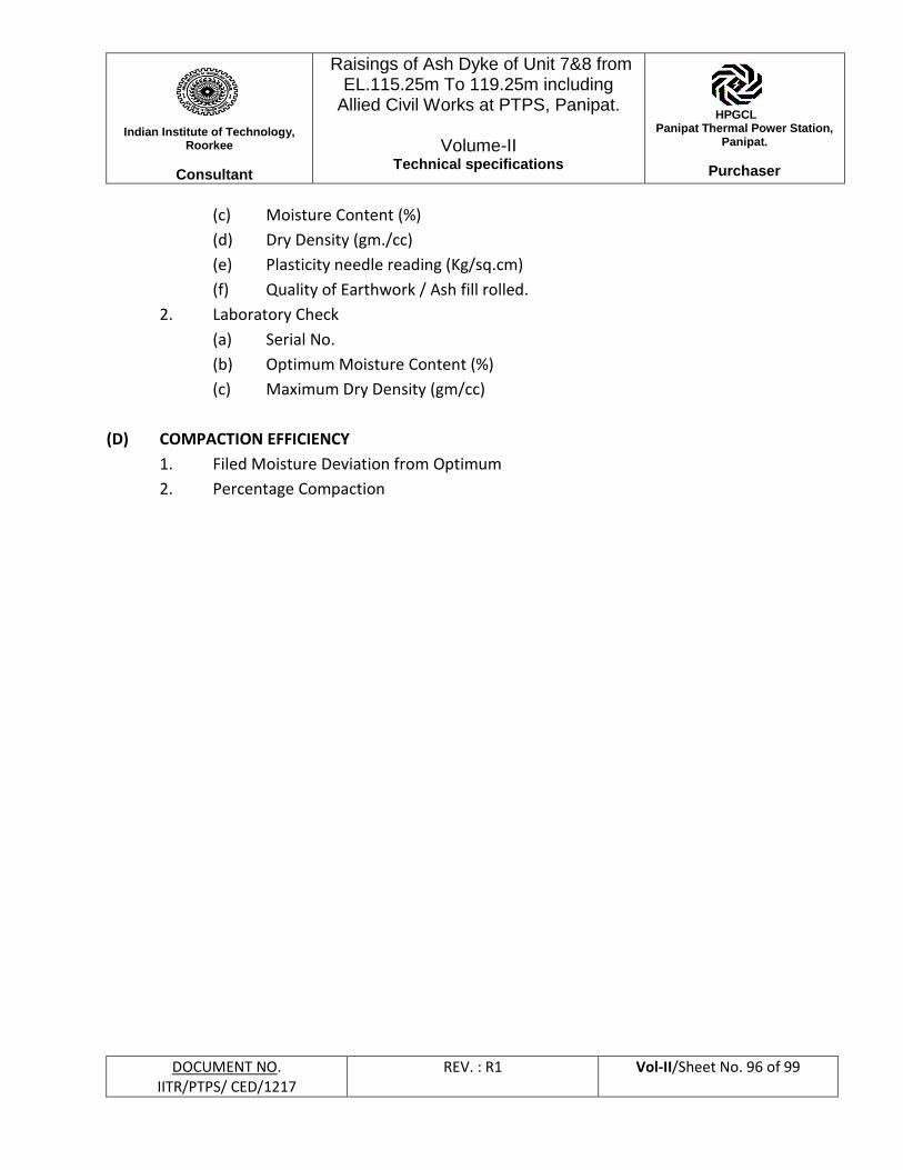
Indian Institute of Technology,
Roorkee
Consultant
Raisings of Ash Dyke of Unit 7&8 from EL.115.25m To 119.25m including
Allied Civil Works at PTPS, Panipat.
Volume-II Technical specifications
HPGCL Panipat Thermal Power Station,
Panipat.
Purchaser
DOCUMENT NO. IITR/PTPS/ CED/1217
REV. : R1 Vol-II/Sheet No. 96 of 99
(c) Moisture Content (%)
(d) Dry Density (gm./cc)
(e) Plasticity needle reading (Kg/sq.cm)
(f) Quality of Earthwork / Ash fill rolled.
2. Laboratory Check
(a) Serial No.
(b) Optimum Moisture Content (%)
(c) Maximum Dry Density (gm/cc)
(D) COMPACTION EFFICIENCY
1. Filed Moisture Deviation from Optimum
2. Percentage Compaction
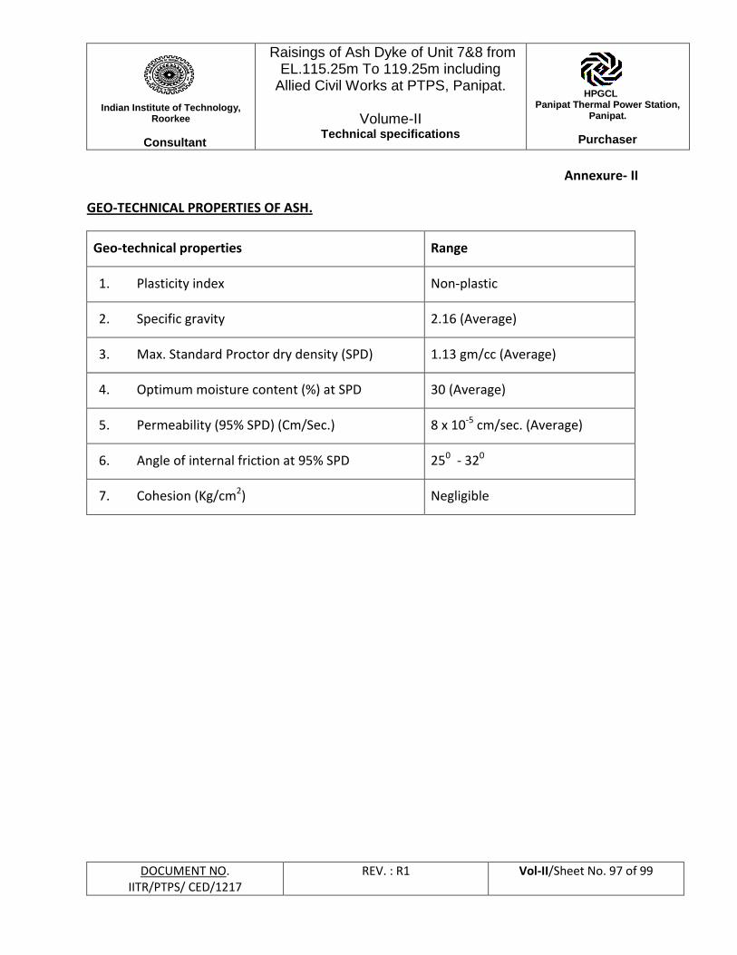
Indian Institute of Technology,
Roorkee
Consultant
Raisings of Ash Dyke of Unit 7&8 from EL.115.25m To 119.25m including
Allied Civil Works at PTPS, Panipat.
Volume-II Technical specifications
HPGCL Panipat Thermal Power Station,
Panipat.
Purchaser
DOCUMENT NO. IITR/PTPS/ CED/1217
REV. : R1 Vol-II/Sheet No. 97 of 99
Annexure- II
GEO-TECHNICAL PROPERTIES OF ASH.
Geo-technical properties Range
1. Plasticity index Non-plastic
2. Specific gravity 2.16 (Average)
3. Max. Standard Proctor dry density (SPD) 1.13 gm/cc (Average)
4. Optimum moisture content (%) at SPD 30 (Average)
5. Permeability (95% SPD) (Cm/Sec.) 8 x 10⁻⁵ cm/sec. (Average)
6. Angle of internal friction at 95% SPD 250 - 320
7. Cohesion (Kg/cm2) Negligible

Indian Institute of Technology,
Roorkee
Consultant
Raisings of Ash Dyke of Unit 7&8 from EL.115.25m To 119.25m including
Allied Civil Works at PTPS, Panipat.
Volume-II Technical specifications
HPGCL Panipat Thermal Power Station,
Panipat.
Purchaser
DOCUMENT NO. IITR/PTPS/ CED/1217
REV. : R1 Vol-II/Sheet No. 98 of 99
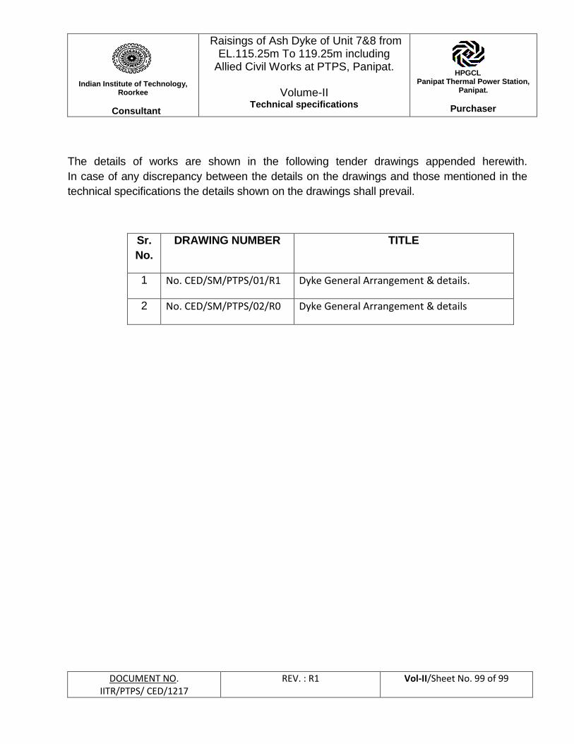
Indian Institute of Technology,
Roorkee
Consultant
Raisings of Ash Dyke of Unit 7&8 from EL.115.25m To 119.25m including
Allied Civil Works at PTPS, Panipat.
Volume-II Technical specifications
HPGCL Panipat Thermal Power Station,
Panipat.
Purchaser
DOCUMENT NO. IITR/PTPS/ CED/1217
REV. : R1 Vol-II/Sheet No. 99 of 99
The details of works are shown in the following tender drawings appended herewith.
In case of any discrepancy between the details on the drawings and those mentioned in the
technical specifications the details shown on the drawings shall prevail.
Sr.
No.
DRAWING NUMBER TITLE
1 No. CED/SM/PTPS/01/R1 Dyke General Arrangement & details.
2 No. CED/SM/PTPS/02/R0 Dyke General Arrangement & details


![]Three raisings from the dead vol 2](https://img.pdfslide.us/doc/110x75/5a6493ac7f8b9a76568b4b91/three-raisings-from-the-dead-vol-2.jpg)