Embed Size (px)
Citation preview

1 / 24
87045 LIMOGES Cedex Phone : 05 55 06 87 87 – Fax : 05 55 06 88 88
Raised Floor system Number(s) :
6897 55/67/70/71/73/74/77/78/80/81/82/83/85/86/87/88/89,
6896 30/31/32/33/38/39/40/41/42/43/48/49/60/61/92/93
COCOCOCONTENTS NTENTS NTENTS NTENTS PAGES
1.Range 1 to 3 2.Installation process 4 to 10 3.Products détails 11 to 22 4.Technical characteristics 22 to 24
1 RANGE.
Data sheet : F01021EN/00 Updated : 19/05/10 Created : 19/05/10
Flat angle
Trunking
Riser
End cap
Lid & trim
Junction box
Coupler
Full backbox
Support frame
Fixing brackets
Wiring accessory plates

2 / 24
Raised Floor system Number(s) :
6897 55/67/70/71/73/74/77/78/80/81/82/83/85/86/87/88/89,
6896 30/31/32/33/38/39/40/41/42/43/48/49/60/61/92/93
CONTENTS
1 RANGE pages 1 to 3 1- Raised Floor provides adaptable power, data, aud io & video distribution in raised floors. 2- Raised Floor System 3- Cable Capacity Guide 2 INSTALLATION PROCESS pages 4 to 10 1- Installation. 2- Junction box ref 6896 78/80/81 3- Support frame ref 6896 39/49 4- Full backbox (frame + support) ref 6896 38/48 5- Lid & trim ref 6896 30/31/32/33/40/41/42/43 3 PRODUCT DETAILS pages 11 to 22 1- Junction Boxes ref 6897 78/80/81 2- Riser ref 6897 82/83 3- Trunkings ref 6897 70/71 4- Fixing brackets ref 6897 55 5- Coupler ref 6897 77 6- Leveling brackets ref 6897 87/89 7- Flat angle ref 6897 73/74 8- End cap ref 6897 85/86 9- Modules ref 6896 60/61 10- Full backbox ref 6896 38/48 11- Support frame ref 6896 39/49 12- Wiring Accessory Plates 13- Lid & trim ref 6896 30/31/32/33/40/41/42/43 14- Stainless steel insert ref 6896 92/93 4 TECHNICAL CHARACTERISTICS page 23
1 RANGE. 1- Raised Floor box provides adaptable power and da ta distribution in raised floors. The system ensures a fast and simple installation. Designed to support Cat 6 structured cabling systems. Lid & trim are IP20 rated in accordance with EN 50085-2-2 and EN 60670-23 Choice of 3 or 4 compartments lid & trim. Self Closing lid in accordance with IEC 61534-22. Lid & trim: plastic material ABS/PA 6.6 FV Rigid & flexible exits: plastic material ABS/TPEE Stainless steel insert: stainless steel material AISI 304 2- Raised Floor System: Materials Pre-galvanised steel (DX51D Z275 MAC) Fire: The outer casing of the floor outlet box is manufactured from metal and is no-combustible. Chemical resistance: Non corrosive. Water absorption: The floor outlet boxes are for use in situations where the cleaning method used does not result in the formation of pools of liquid or soaking of the floor surface. Degree of protection: Enclosure classification of IP20 when installed in accordance with the instructions set out in the installation guide. Ambient Temperature Range: Handling and storage -25°C minimum During installation -5°C 60°C Application -5°C 40°C Metal trunking and Accessories: Material Pre-galvanised sheet steel (DX51D Z275 MAC) Cleaning: The exterior should only be cleaned using a damp cloth
Data sheet : F01021EN/00 Updated : 19/05/10 Created : 19/05/10

3 / 24
Raised Floor system Number(s) :
6897 55/67/70/71/73/74/77/78/80/81/82/83/85/86/87/88/89,
6896 30/31/32/33/38/39/40/41/42/43/48/49/60/61/92/93
1 RANGE. 3- Cable Capacity Guide: The number and location of boxes will depend on the end user requirements. If the furniture layout is available, a lid & trim should be considered for each workstation or desk. If the final furniture layout is not available, the minimum recommended distribution is one lid & trim for every 10m², and the maximum being one lid & trim per 4m². Compartment 1, 2 and 3 have the same capacity
45% available cross section
for power cables
Number of PVC stranded
Twin & earth
Metal
trunking
Section 45% Fill
mm²
1,5² Ø3.3 mm
2,5² Ø4 mm
4² Ø4.6 mm
6² Ø5.2 mm
10² Ø6.7 mm
16² Ø7.8 mm
25² Ø9.7 mm
2,5² Ø10.5 mm
4² Ø11.2 mm
6² Ø13.7 mm
225x38
1 2 3 1134 132 90 68 53 32 24 15 13 11 8
300x38
1 2 3 1584 184 126 95 75 45 33 21 18 16 11
for data cables
Number of Data cables
Metal
trunking
Section
45% Fill mm² cat 5E UTP Ø5.5mm
cat 5E STP Ø6mm
cat 6 UTP Ø6.5mm cat 6 STP Ø7mm
225x38
1 2 3 1134 38 32 27 23
300x38
1 2 3 1584 52 44 38 32
Raised trunking system complies with EN50085-1: 2005 and draft EN50085 Part 2-2. The above table gives the available capacity units on 45% factor, applied to the internal wiring area.
Data sheet : F01021EN/00 Updated : 19/05/10 Created : 19/05/10
1 2
3

4 / 24
Raised Floor system Number(s) :
6897 55/67/70/71/73/74/77/78/80/81/82/83/85/86/87/88/89,
6896 30/31/32/33/38/39/40/41/42/43/48/49/60/61/92/93
2 INSTALLATION PROCESS 1- Installation. A- Remove the raised access floor tiles along the required pathway
Fix the junction boxes, risers and flat angles to the slab at the required location
(level if required, use leveling brackets cat.No 6897 88)
Data sheet : F01021EN/00 Updated : 19/05/10 Created : 19/05/10

5 / 24
Raised Floor system Number(s) :
6897 55/67/70/71/73/74/77/78/80/81/82/83/85/86/87/88/89,
6896 30/31/32/33/38/39/40/41/42/43/48/49/60/61/92/93
2 INSTALLATION PROCESS (continued) 1- Installation (continued) B- Fix trunking and all accessories with fixing brackets to the slab (1- with levelling, 2- without levelling)
C- Remove all covers for cabling
D- Cut raised access floor tiles according to backbox size and earth the system (maximum every 10meters)
Data sheet : F01021EN/00 Updated : 19/05/10 Created : 19/05/10
Full Backbox Support frame
11188
11188
1
2

6 / 24
Raised Floor system Number(s) :
6897 55/67/70/71/73/74/77/78/80/81/82/83/85/86/87/88/89,
6896 30/31/32/33/38/39/40/41/42/43/48/49/60/61/92/93
2 INSTALLATION PROCESS (continued) 2- Junction box ref 6896 78/80/81
The junction box is used for simple junction or connection point. The junction box should be positioned directly on the slab and provides access to cables at the intersection of trunkings or changes of direction. The junction box allows deviation of power and data cable, adjustable height with 4 leveling brackets ref 6897 88 (details on page 5) Junction Boxes are supplied as a base with a lid and flyovers 1- Fix the junction box on the slab and remove the lid 2- pull the flyovers out of the junction
3- Connect to the trunking with screws and remove the covers 4- cable the trunking
4- Refix the lid and cover of the trunking
Data sheet : F01021EN/00 Updated : 19/05/10 Created : 19/05/10

7 / 24
Raised Floor system Number(s) :
6897 55/67/70/71/73/74/77/78/80/81/82/83/85/86/87/88/89,
6896 30/31/32/33/38/39/40/41/42/43/48/49/60/61/92/93
2 INSTALLATION PROCESS (continued) 3- Support frame ref 6896 39/49
Tolerance for dimensions A and B = 0 / +2mm 1- Remove all covers for cabling and cut raised floor tiles according to backbox size
2- Backbox installation in the raised access floor tile is a push and fit principle. 3- cable the trunking
Fixing by means for screw also possible
Data sheet : F01021EN/00 Updated : 19/05/10 Created : 19/05/10

8 / 24
Raised Floor system Number(s) :
6897 55/67/70/71/73/74/77/78/80/81/82/83/85/86/87/88/89,
6896 30/31/32/33/38/39/40/41/42/43/48/49/60/61/92/93
2 INSTALLATION PROCESS (continued) 3- Support frame ref 6896 39/49 (continued) 4 - On trunking, remove knockouts to fit flexible conduit (Ø21mm)
5- Fix the wiring accessory plates and earth the system
6- For the modular backbox, clip the individual modules to desired depth
Data sheet : F01021EN/00 Updated : 19/05/10 Created : 19/05/10

9 / 24
Raised Floor system Number(s) :
6897 55/67/70/71/73/74/77/78/80/81/82/83/85/86/87/88/89,
6896 30/31/32/33/38/39/40/41/42/43/48/49/60/61/92/93
2 INSTALLATION PROCESS (continued) 4- Full backbox (frame + support) ref 6896 38/48
Tolerance for dimensions A and B = 0 / +2mm 1- Remove all covers for cabling and cut raised floor tiles according to backbox size 2- cable the trunking
3- Backbox installation in the raised access floor tile is a push and fit principle, on trunking, remove knockouts to fit flexible conduit. 4 - Fix the wiring accessory plates and earth the system.
fixing by means of screw also possible
Data sheet : F01021EN/00 Updated : 19/05/10 Created : 19/05/10
10 / 24
Raised Floor system Number(s) :
6897 55/67/70/71/73/74/77/78/80/81/82/83/85/86/87/88/89,
6896 30/31/32/33/38/39/40/41/42/43/48/49/60/61/92/93
2 INSTALLATION PROCESS (continued) 5- Lid & trim ref 6896 30/31/32/33/40/41/42/43
Finally, to install the finish flooring:
Locking system: The floor box can be locked by means of a locking system (hidden under the opening handle); For safety reasons, floor box should not be locked when in use.
Data sheet : F01021EN/00 Updated : 19/05/10 Created : 19/05/10
After installing wiring the accessory plates, push down the lid & trim onto the full backbox/support frame
1 – To fit carpet, pull the levers upwards on both sides to take out the lid and trim.
2 – Fit the carpet and push down the lid and trim on the full backbox/support frame (push and fit principle)
11 / 24
Raised Floor system Number(s) :
6897 55/67/70/71/73/74/77/78/80/81/82/83/85/86/87/88/89,
6896 30/31/32/33/38/39/40/41/42/43/48/49/60/61/92/93
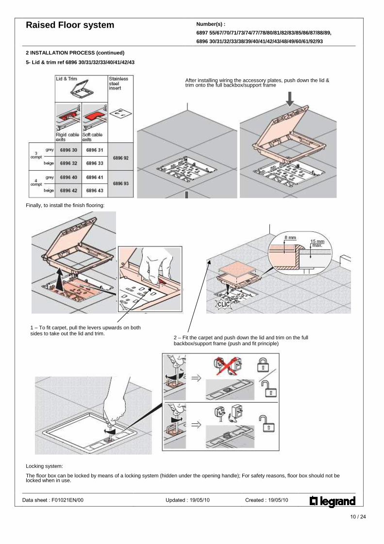
3 PRODUCT DETAILS 1- Junction Boxes ref 6897 78/80/81
Reference
To use with junction of
6897 80
2 trunkings 225x38mm
6897 81
2 trunkings 300x38mm
6897 78
1 trunking 225x38mm and
1 trunking 300x38mm Dimensions (mm):
Reference
X
Y
Z
6897 80
285
285
39.2
6897 81
360
360
39.2
6897 78
285
360
39.2
Data sheet : F01021EN/00 Updated : 19/05/10 Created : 19/05/10
12 / 24
Raised Floor system Number(s) :
6897 55/67/70/71/73/74/77/78/80/81/82/83/85/86/87/88/89,
6896 30/31/32/33/38/39/40/41/42/43/48/49/60/61/92/93
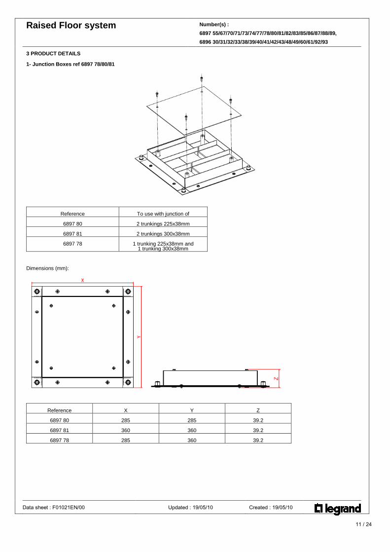
3 PRODUCT DETAILS (continued) 2- Riser ref 6897 82/83 The riser allows the change of direction (horizontal to vertical). Conduit or trunking can be run vertically or horizontally from the riser Allows the junction in interior angle (between the floor/wall) of two trunkings of the same section:
Reference
Use for trunking
6897 82
225x38mm metal
6897 83
300x38mm metal
Dimensions (mm):
Reference
X
Y
Z
6897 82
225
38
201
6897 83
300
38
201
Installation of riser: 1- Fit the riser against the wall 2- Connect the trunking to the riser with the coupler
Data sheet : F01021EN/00 Updated : 19/05/10 Created : 19/05/10
Coupler

13 / 24
Raised Floor system Number(s) :
6897 55/67/70/71/73/74/77/78/80/81/82/83/85/86/87/88/89,
6896 30/31/32/33/38/39/40/41/42/43/48/49/60/61/92/93
3 PRODUCT DETAILS 3- Trunkings ref 6897 70/71
Provides EMC Screening Manufactured from pre-galvanised steel sheet Delivered in standard length 2.44m Standard thickness: 1mm for body/dividers/cover Number of compartments: 3 compartments. Standard depth: 38mm Metal trunkings allows: - distribution of power data underneath to the raised floor. The trunking has 12 knockouts Ø 21mm (for connection of the flexible conduits)length of 2.44m
Center distance between knockouts:
Dimensions (mm) a b Trunking 225x38 74 74 Trunking 300x38 100 100
Data sheet : F01021EN/00 Updated : 19/05/10 Created : 19/05/10
225x38 metal
knockouts
a b

14 / 24
Raised Floor system Number(s) :
6897 55/67/70/71/73/74/77/78/80/81/82/83/85/86/87/88/89,
6896 30/31/32/33/38/39/40/41/42/43/48/49/60/61/92/93
3 PRODUCT DETAILS (continued) 4- Fixing brackets ref 6897 55
Dimensions To fix trunking on the slab.
Reference
Use for trunking
6897 55
225/300x38mm metal
Thickness: 1.5mm 5- Coupler ref 6897 77
Used to connect two trunking lenghts
Reference
Use for trunking
6897 77
225/300x38mm metal
Dimensions (mm):
Reference
X
Y
6897 77
55
32
Thickness: 1mm Comes with 2 screws M6x10
Data sheet : F01021EN/00 Updated : 19/05/10 Created : 19/05/10

15 / 24
Raised Floor system Number(s) :
6897 55/67/70/71/73/74/77/78/80/81/82/83/85/86/87/88/89,
6896 30/31/32/33/38/39/40/41/42/43/48/49/60/61/92/93
3 PRODUCT DETAILS (continued) 6- Leveling brackets ref 6897 87/89
- To raise trunking level up to 10mm - To connect two trunking lenghts - To fix the levelling brackets, please used the screws M6x10 delivered with the couplers
Reference
Use for trunking
6897 87
225x38mm metal
6897 89
300x38mm metal
Dimensions (mm):
Reference
X
W
6897 87
225
25
6897 89
300
25
Thickness: 1.5mm Leveling brackets ref 6897 88: To raise junction box/backbox level up to 10mm
Dimensions (mm) Delivered in set of 4
Data sheet : F01021EN/00 Updated : 19/05/10 Created : 19/05/10
X
W
5.5mm

16 / 24
Raised Floor system Number(s) :
6897 55/67/70/71/73/74/77/78/80/81/82/83/85/86/87/88/89,
6896 30/31/32/33/38/39/40/41/42/43/48/49/60/61/92/93
3 PRODUCT DETAILS (continued) 7- Flat angle ref 6897 73/74
Allows the junction in a flat angle of two equal sized trunking: - fix to the trunking by means of couplers - flat angles are 90° - flat angles are delivered with base, cover and partitions
Reference
Use for trunking
6897 73
225x38mm metal
6897 74
300x38mm metal
Dimensions (mm):
Reference
X
Y
Z
6897 73
225
273
38
6897 74
300
348
38
Data sheet : F01021EN/00 Updated : 19/05/10 Created : 19/05/10
Cover
Dividers
Base
Y
17 / 24
Raised Floor system Number(s) :
6897 55/67/70/71/73/74/77/78/80/81/82/83/85/86/87/88/89,
6896 30/31/32/33/38/39/40/41/42/43/48/49/60/61/92/93
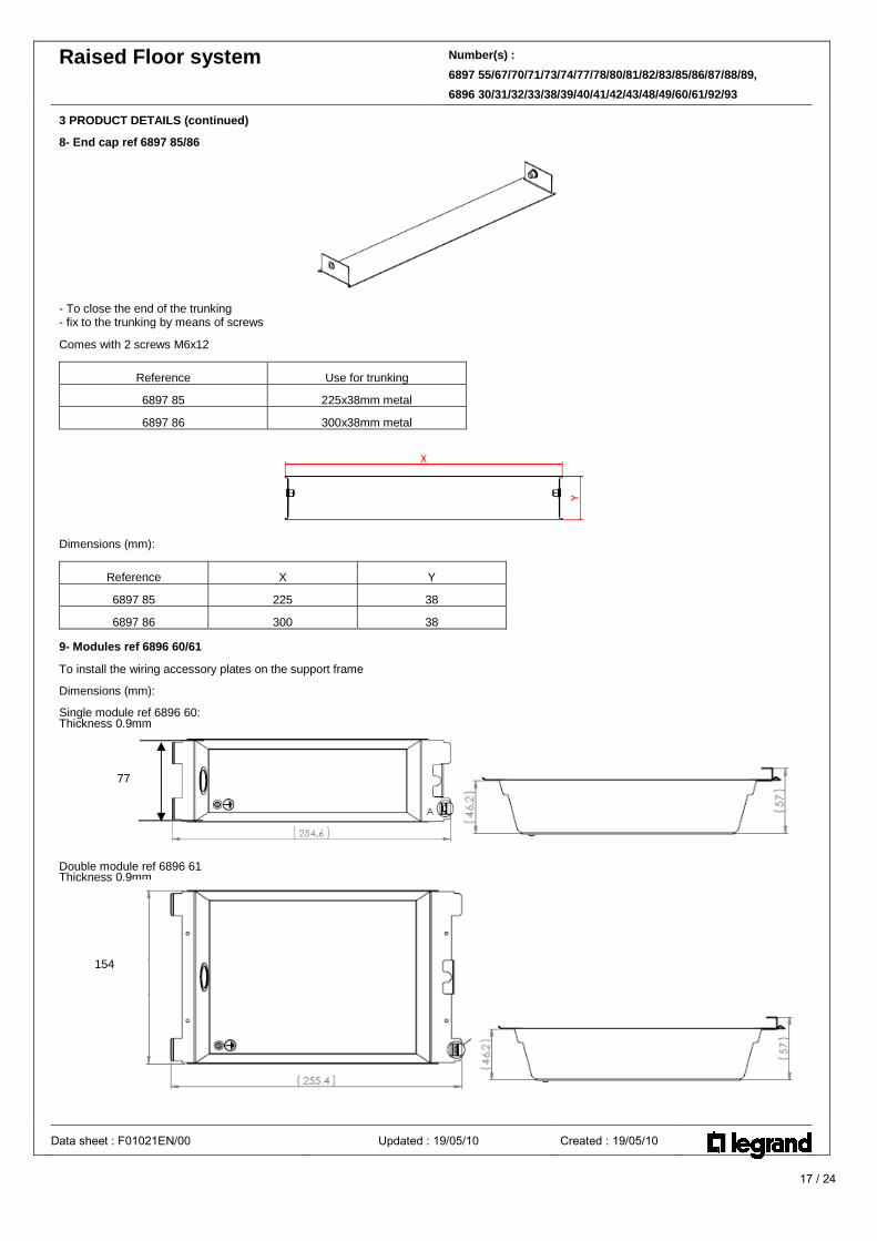
3 PRODUCT DETAILS (continued) 8- End cap ref 6897 85/86
- To close the end of the trunking - fix to the trunking by means of screws Comes with 2 screws M6x12
Reference
Use for trunking
6897 85
225x38mm metal
6897 86
300x38mm metal
Dimensions (mm):
Reference
X
Y
6897 85
225
38
6897 86
300
38
9- Modules ref 6896 60/61 To install the wiring accessory plates on the support frame Dimensions (mm): Single module ref 6896 60: Thickness 0.9mm
Double module ref 6896 61 Thickness 0.9mm
Data sheet : F01021EN/00 Updated : 19/05/10 Created : 19/05/10
77
154
18 / 24
Raised Floor system Number(s) :
6897 55/67/70/71/73/74/77/78/80/81/82/83/85/86/87/88/89,
6896 30/31/32/33/38/39/40/41/42/43/48/49/60/61/92/93
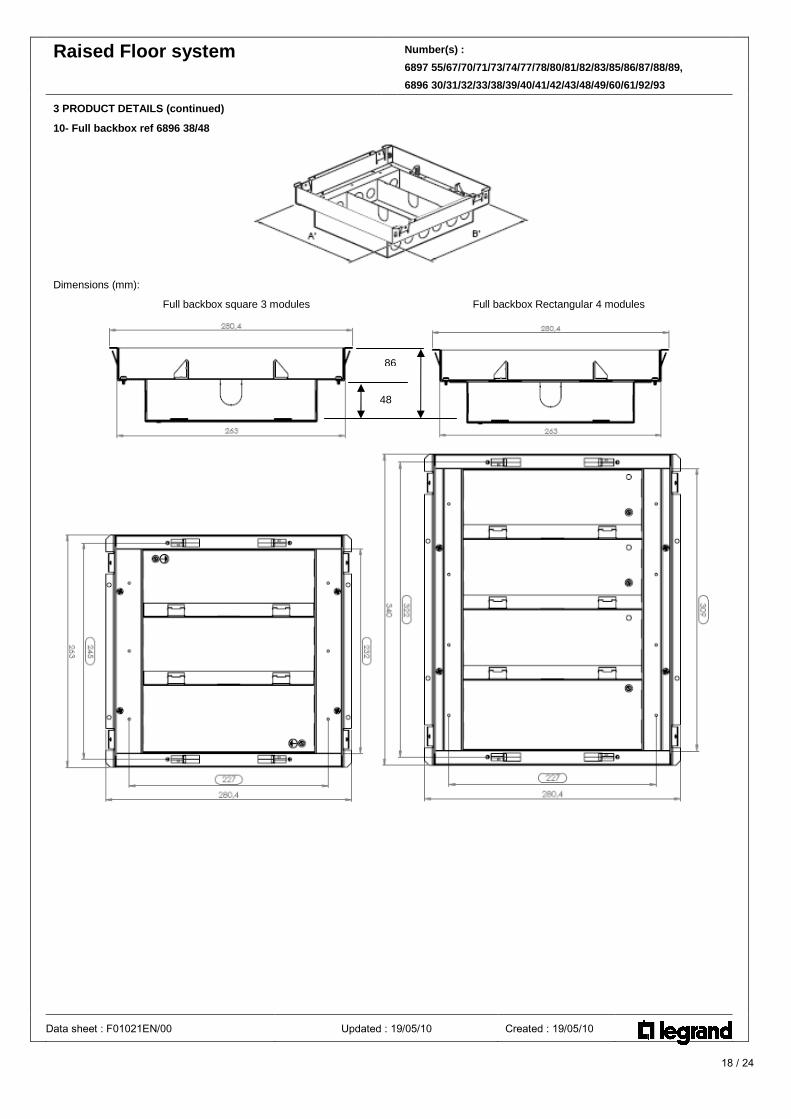
3 PRODUCT DETAILS (continued) 10- Full backbox ref 6896 38/48
Dimensions (mm): Full backbox square 3 modules Full backbox Rectangular 4 modules
Data sheet : F01021EN/00 Updated : 19/05/10 Created : 19/05/10
48
86

19 / 24
Raised Floor system Number(s) :
6897 55/67/70/71/73/74/77/78/80/81/82/83/85/86/87/88/89,
6896 30/31/32/33/38/39/40/41/42/43/48/49/60/61/92/93
3 PRODUCT DETAILS (continued) 11- Modular backbox ref 6896 39/49 Allow installation of power and data plates and fitting of a lid & trim : Adjustable height of the modules to 4 positions on the support frame.
Dimensions (mm): dular backbox square, 3 modules Modular backbox Rectangle, 4 modules
Module in high position Module in low position
Note: dimensions of the different positions of the modules can be found on the page 23 (technical characteristics)
Data sheet : F01021EN/00 Updated : 19/05/10 Created : 19/05/10
263 340
86 107

20 / 24
Raised Floor system Number(s) :
6897 55/67/70/71/73/74/77/78/80/81/82/83/85/86/87/88/89,
6896 30/31/32/33/38/39/40/41/42/43/48/49/60/61/92/93
3 PRODUCT DETAILS (continued) 12- Wiring Accessory Plates Standard Plates compatible with all backboxes.
6896 62 Wiring Accessory Plate - 77mm - blank 6896 63
Wiring Accessory Plate - 154mm - double
6896 65 Wiring Accessory Plate - 77mm - twin unswitched socket 13 A
6896 66 Wiring Accessory Plate - 77mm - twin switched socket double pole13 A
6896 67 Wiring Accessory Plate - 77mm - twin switched socket clean earth13 A 689668
Wiring Accessory Plate - 154mm - 2 twin switched sockets double pole13 A
6896 69 Wiring Accessory Plate - 77mm - twin switched socket staggered double pole
6896 70 Wiring Accessory Plate - 77mm - 2x6C knockouts
6896 71 Wiring Accessory Plate - 77mm - 4x6C knockouts
6896 72 Wiring Accessory Plate - 77mm - 2x1mod Artéor
6896 73 Wiring Accessory Plate - 77mm - 2x2mod Artéor
6896 74 Wiring Accessory Plate - 77mm - 3x2mod Artéor
6896 75 Wiring Accessory Plate - 77mm - 2x6C knockouts wave
6896 76 Wiring Accessory Plate - 77mm - 4x6C knockouts wave
6896 77 Wiring Accessory Plate - 77mm - 2x3mod Artéor
6896 78 Wiring Accessory Plate - 77mm - 2x2mod Artéor wave Dimensions for wiring accessory plates: single plate 237x77mm, double plate237x154mm Single and double Plates are supplied with epoxy power coating Silver Grey colour Wiring accessory plates are delivered with 2 screws M3x8 Designed to be compatible with Cat 6 structured cabling systems. Earth the wiring accessory plates by using the screw on bottom side
Note: Staggered Wiring Accessory Plate to avoid interferance of plug cords.
Data sheet : F01021EN/00 Updated : 19/05/10 Created : 19/05/10
Earth marking
Technical information sockets : - Mechanism Synergy - 250V - Terminal screws - Compact mechanism for easy fitting - British standard1363-2
21 / 24
Raised Floor system Number(s) :
6897 55/67/70/71/73/74/77/78/80/81/82/83/85/86/87/88/89,
6896 30/31/32/33/38/39/40/41/42/43/48/49/60/61/92/93
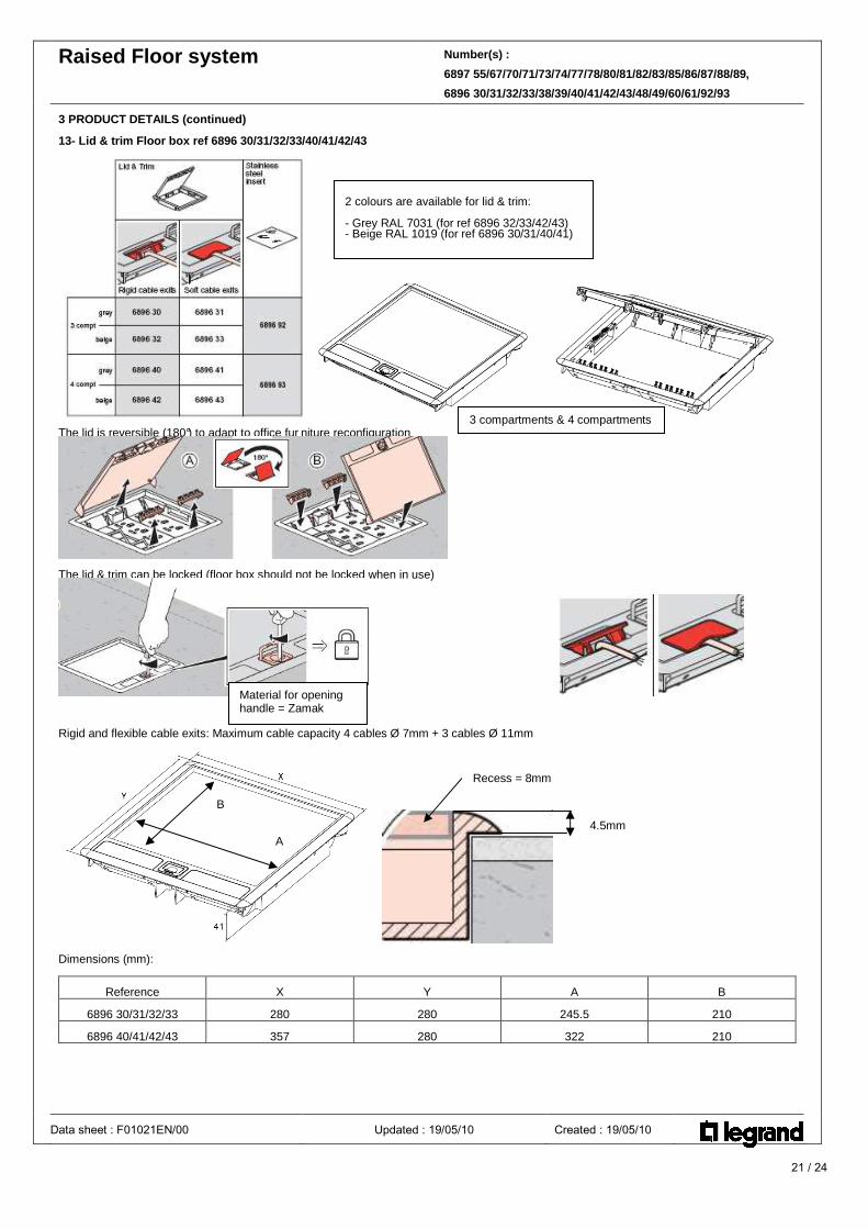
3 PRODUCT DETAILS (continued) 13- Lid & trim Floor box ref 6896 30/31/32/33/40/41 /42/43
The lid is reversible (180°) to adapt to office fur niture reconfiguration
The lid & trim can be locked (floor box should not be locked when in use)
Rigid and flexible cable exits: Maximum cable capacity 4 cables Ø 7mm + 3 cables Ø 11mm
Dimensions (mm):
Reference
X
Y
A
B
6896 30/31/32/33
280
280
245.5
210
6896 40/41/42/43
357
280
322
210
Data sheet : F01021EN/00 Updated : 19/05/10 Created : 19/05/10
4.5mm
Recess = 8mm
B
A
2 colours are available for lid & trim: - Grey RAL 7031 (for ref 6896 32/33/42/43) - Beige RAL 1019 (for ref 6896 30/31/40/41)
3 compartments & 4 compartments
Material for opening handle = Zamak
22 / 24
Raised Floor system Number(s) :
6897 55/67/70/71/73/74/77/78/80/81/82/83/85/86/87/88/89,
6896 30/31/32/33/38/39/40/41/42/43/48/49/60/61/92/93
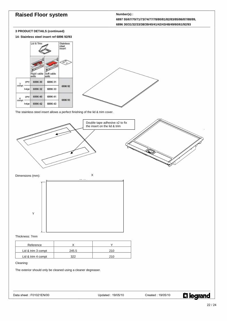
3 PRODUCT DETAILS (continued) 14- Stainless steel insert ref 6896 92/93
The stainless steel insert allows a perfect finishing of the lid & trim cover.
Dimensions (mm):
Thickness: 7mm
Reference
X
Y
Lid & trim 3 compt
245.5
210
Lid & trim 4 compt
322
210
Cleaning: The exterior should only be cleaned using a cleaner degreaser.
Data sheet : F01021EN/00 Updated : 19/05/10 Created : 19/05/10
Y
X
Double tape adhesive x2 to fix the insert on the lid & trim
23 / 24
Raised Floor system Number(s) :
6897 55/67/70/71/73/74/77/78/80/81/82/83/85/86/87/88/89,
6896 30/31/32/33/38/39/40/41/42/43/48/49/60/61/92/93
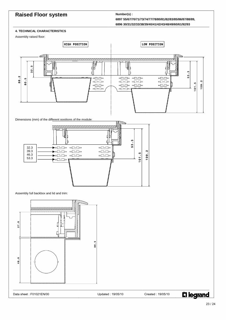
4. TECHNICAL CHARACTERISTICS Assembly raised floor:
Dimensions (mm) of the different positions of the module:
Assembly full backbox and lid and trim:
Data sheet : F01021EN/00 Updated : 19/05/10 Created : 19/05/10
32.3 39.3 46.3 53.3

24 / 24
Raised Floor system Number(s) :
6897 55/67/70/71/73/74/77/78/80/81/82/83/85/86/87/88/89,
6896 30/31/32/33/38/39/40/41/42/43/48/49/60/61/92/93
4. TECHNICAL CHARACTERISTICS Classification for Raised floor (standard EN 50085-2-2)
6.2 Resistance to impact for installation and application 2.0J 6.3 Minimum storage and transport temperature - 25°C 6.3 Minimum installation and application temperature - 5°C 6.3 Maximum application temperature + 60°C 6.4 Resistance to flame propagation Non-flame propagating 6.5 Electrical continuity characteristic With electrical continuity characteristic (Metal ducting &
accessories) 6.6 Electrical insulating characteristic Without electrical insulating characteristic (Metal ducting &
accessories) 6.7 Degrees of protection provided by enclosure IP 20 6.9 The system access cover retention With a tool 6.101 Floor treatment for dry-treatment of floor 6.102 Resistance to vertical load applied through small surface area
1500 N*
6.103 Optional classification: resistance to vertical load applied through large surface area
3 000 N
Rated voltage (PVC ducting) 500V Protection against mechanical impact IK08 Linear impedance in mΩ/m of trunking length 5 mΩ/m
*for 4 compartment, resistance to vertical load applied over a small surface area = 750N Composition and functions for Raised floor system:
Important: Every 10meters maximum, earth the system (with ref 11188)
Metal trunking and Accessories:
CAT N° Designation to earth the system
689770 Trunking Yes
689771 Trunking Yes
689638 Full Backbox 3 compt Yes
689648 Full Backbox 4 compt Yes
689660 Single Basket Yes
689661 Double Basket Yes Note: earth the wiring accessory plates ( by using the screw on bottom side ) page 20
Data sheet : F01021EN/00 Updated : 19/05/10 Created : 19/05/10