Embed Size (px)
Citation preview

WR-CLIK Wireless Rain-ClikWRF-CLIK Wireless Rain/Freeze-Clik
Rain Sensor Shutoff for Automatic Irrigation Systems
Owner’s Manual and Installation Instructions

Table of ConTenTs
Features .................................................................................................................................................................3Wireless Rain-Clik™ Components ........................................................................................................................4Mounting the Receiver .........................................................................................................................................6Mounting the Transmitter ..................................................................................................................................10Adjustments and Operation ..............................................................................................................................11FCC Notice..........................................................................................................................................................17FCC Declaration of Conformity .........................................................................................................................18Industry of Canada Notice .................................................................................................................................20CE & Australia Notice .........................................................................................................................................21Notes ...................................................................................................................................................................22
3
feaTures
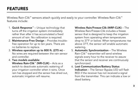
Wireless Rain-Clik™ sensors attach quickly and easily to your controller. Wireless Rain-Clik™ features include:
1. Quick Response™ – Unique technology that turns off the irrigation system immediately rather than after it has accumulated a fixed amount of rain. No calibration is required.
2. Maintenance-Free Design – Provides trouble-free operation for up to ten years. There are no batteries to replace.
3. Wireless operation up to 800 ft. (275 m) – No wires are required between the rain sensor and controller.
4. Two models available: Wireless Rain-Clik™ (WR-CLIK) – Acts as a switch to deactivate automatic watering of your irrigation controller when it rains. Once rain has stopped and the sensor has dried out, automatic irrigation will resume.
Wireless Rain/Freeze-Clik (WRF-CLIK) – The Wireless Rain/Freeze-Clik includes a freeze sensor that is designed to keep the irrigation system from operating when temperatures drop to 37˚F or below. When temperatures rise above 37˚F, the sensor will enable automatic watering.
5. Automatic Synchronization – The Wireless Rain-Clik™ transmitter will send wireless signals every hour to the receiver to assure that the sensor and receiver are continuously synchronized.
6. Lost Communication/Battery Status Indication – The Sensor Bypass LED will flash RED if the receiver has not received a signal from the transmitter. This can indicate a low or dead battery.
4
Wireless rain-Clik™ ComponenTs
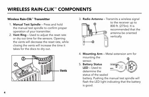
Wireless rain-Clik™ Transmitter
1. Manual Test Spindle – Press and hold the manual test spindle to confirm proper operation of your transmitter.
2. Vent Ring – Used to adjust the reset rate or dry out time for the sensors. Opening the vents will decrease the reset rate, while closing the vents will increase the time it takes for the discs to dry out.
3. Radio Antenna – Transmits a wireless signal to the receiver up to 800 ft. (275m). It is recommended that the antenna be oriented vertically
4. Mounting Arm – Metal extension arm for mounting the sensor.
5. Battery Status LED – Used to determine the status of the sealed battery. Pushing the manual test spindle will flash the LED light indicating that the battery is good.
2
1
Vents
4
3
5
5
Wireless rain-Clik™ ComponenTs
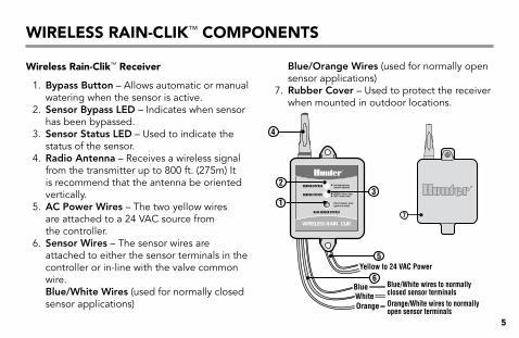
Wireless rain-Clik™ receiver
1. Bypass Button – Allows automatic or manual watering when the sensor is active.
2. Sensor Bypass LED – Indicates when sensor has been bypassed.
3. Sensor Status LED – Used to indicate the status of the sensor.
4. Radio Antenna – Receives a wireless signal from the transmitter up to 800 ft. (275m) It is recommend that the antenna be oriented vertically.
5. AC Power Wires – The two yellow wires are attached to a 24 VAC source from the controller.
6. Sensor Wires – The sensor wires are attached to either the sensor terminals in the controller or in-line with the valve common wire. Blue/White Wires (used for normally closed sensor applications)
Blue/Orange Wires (used for normally open sensor applications)
7. Rubber Cover – Used to protect the receiver when mounted in outdoor locations.
WhiteBlue
Yellow to 24 VAC Power
Orange
SENSOR STATUS
SENSOR BYPASS
Press to bypass, press again to re-enable
GREEN = Sensor is dryRED = Sensor is wet
Red light indicatessensor is bypassed
RAIN SENSOR BYPASS
Blue/White wires to normallyclosed sensor terminalsOrange/White wires to normallyopen sensor terminals
23
5
6
4
17
6
mounTing The reCeiver
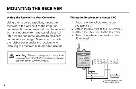
Wiring the receiver to Your Controller
Using the hardware supplied, mount the receiver to the wall next to the irrigation controller. It is recommended that the receiver be installed away from sources of electrical interference and metal objects to maximize communication range. Make sure to attach the rubber cover under the receiver when installing the receiver in an outdoor location.
Warning: This unit is designed to be installed in conjunction with 24 VAC circuits only. Do not use with 110 or 220 VAC circuits.
Wiring the receiver to a hunter srC
1. Attach the two yellow wires to the AC terminals.
2. Attach the blue wire to the RS terminal.3. Attach the white wire to the C terminal.4. Attach the valve common wire to the
RS terminal.
O Used for normally open sensor applications
R RS C 1 AC AC 2 3
W
B
Y
Y
Common Wire to all Valves
SENSOR STATUS
SENSOR BYPASS
Press to bypass, press again to re-enable
GREEN = Sensor is dryRED = Sensor is wet
Red light indicatessensor is bypassed
RAIN SENSOR BYPASS

7
mounTing The reCeiver
Wiring the receiver to a hunter X-Core, pro-C, iCC and i-Core
1. Remove the sensor jumper across the two SEN terminals in the controller.
2. Attach the two yellow wires to the 24 VAC terminals.
3. Attach the blue wire to one SEN terminal and the white wire to the other SEN terminal.
SEN
SEN
C
TEST
P MV
AC
AC
G
REM
B
W
Y
Y
SENSOR STATUS
SENSOR BYPASS
Press to bypass, press again to re-enable
GREEN = Sensor is dryRED = Sensor is wet
Red light indicatessensor is bypassed
RAIN SENSOR BYPASS
Wiring the receiver to a hunter aCC
1. Connect the blue and white wire to any of the four Sensor Terminal pairs (Sen 1 shown).
2. Attach yellow wires to 24VAC and COM terminals.
3. Use features at the “Set Sensor Operation” dial position on ACC to complete setup.
4. See ACC owner’s manual for further details.
8
mounTing The reCeiver
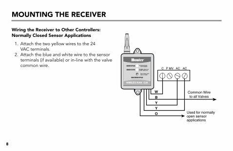
Wiring the receiver to other Controllers: normally Closed sensor applications
1. Attach the two yellow wires to the 24 VAC terminals.
2. Attach the blue and white wire to the sensor terminals (if available) or in-line with the valve common wire.
P MV C AC AC
W
B
Y
Y
O
Common Wire to all Valves
Used for normally open sensor applications
SENSOR STATUS
SENSOR BYPASS
Press to bypass, press again to re-enable
GREEN = Sensor is dryRED = Sensor is wet
Red light indicatessensor is bypassed
RAIN SENSOR BYPASS
9
mounTing The reCeiver
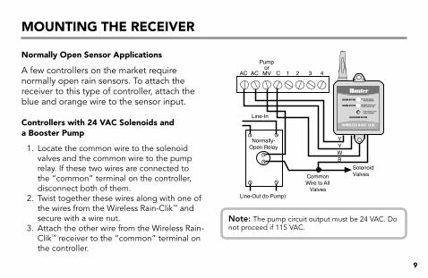
normally open sensor applications
A few controllers on the market require normally open rain sensors. To attach the receiver to this type of controller, attach the blue and orange wire to the sensor input.
Controllers with 24 vaC solenoids and a booster pump
1. Locate the common wire to the solenoid valves and the common wire to the pump relay. If these two wires are connected to the “common” terminal on the controller, disconnect both of them.
2. Twist together these wires along with one of the wires from the Wireless Rain-Clik™ and secure with a wire nut.
3. Attach the other wire from the Wireless Rain-Clik™ receiver to the “common” terminal on the controller.
Normally- Open Relay
1 2 3 4 C
Solenoid Valves Common
Wire to All Valves
Pump or
MV
Line-In
Line-Out (to Pump)
AC AC
YYWB
SENSOR STATUS
SENSOR BYPASS
Press to bypass, press again to re-enable
GREEN = Sensor is dryRED = Sensor is wet
Red light indicatessensor is bypassed
RAIN SENSOR BYPASS
Note: The pump circuit output must be 24 VAC. Do not proceed if 115 VAC.
10
mounTing The TransmiTTer
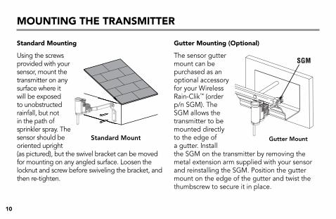
standard mounting
Using the screws provided with your sensor, mount the transmitter on any surface where it will be exposed to unobstructed rainfall, but not in the path of sprinkler spray. The sensor should be oriented upright (as pictured), but the swivel bracket can be moved for mounting on any angled surface. Loosen the locknut and screw before swiveling the bracket, and then re-tighten.
gutter mounting (optional)
The sensor gutter mount can be purchased as an optional accessory for your Wireless Rain-Clik™ (order p/n SGM). The SGM allows the transmitter to be mounted directly to the edge of a gutter. Install the SGM on the transmitter by removing the metal extension arm supplied with your sensor and reinstalling the SGM. Position the gutter mount on the edge of the gutter and twist the thumbscrew to secure it in place.
SGM
Standard Mount Gutter Mount
11
adjusTmenTs and operaTion
hints for mounting the transmitter
• Choose a location such as the side of a building or post. The closer the transmitter is to the receiver, the better the reception. Do not exceed 800 ft (275 m).
• To assure maximum range in communication, mount the receiver and transmitter away from sources of electrical interference (i.e. control panels, transformers, etc.) or metal objects. Best performance is obtained when no physical obstruction is between the transmitter and receiver.
• Correct placement of the Wireless Rain/Freeze-Clik model is important for accurate temperature sensing. The best location would be out of direct sunlight.
• The reset rate refers to the amount of time it takes for the sensor to dry out sufficiently for the sprinkler system to be allowed to come back on. The mounting location will affect this rate. For example, mounting the transmitter in a very sunny location may cause the sensor to dry out sooner than desired. Similarly, mounting the sensor in constant shade may keep the sensor from drying out sooner.
12
adjusTmenTs and operaTion
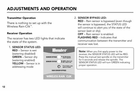
Transmitter operation
There is nothing to set up with the Wireless Rain-Clik™.
receiver operation
The receiver has two LED lights that indicate the state of the system.
1. SENSOR STATUS LED: RED – Sensor is wet (watering disabled) GREEN – Sensor dry (watering enabled) YELLOW – Sensor is in addressing mode
2. SENSOR BYPASS LED: RED – Rain sensor is bypassed (even though the sensor is bypassed, the STATUS LED will continue to alert you of the state of the sensor (wet or dry). OFF – Rain sensor is enabled. FLASHING RED – Indicates that communication between the transmitter and receiver was lost.
SENSOR STATUS
SENSOR BYPASS
Press to bypass, press again to re-enable
GREEN = Sensor is dryRED = Sensor is wet
Red light indicatessensor is bypassed
RAIN SENSOR BYPASS
Note: When you first apply power to the receiver, the SENSOR STATUS LED will be RED. Press the manual test spindle on the transmitter for 5 seconds and release the spindle. The SENSOR STATUS LED will turn GREEN indicating proper operation.
13
adjusTmenTs and operaTion
bypassing the sensor
The sensor may be bypassed by using the built in bypass feature on the receiver. To bypass the sensor, press the SENSOR BYPASS button on the receiver. The bypass status light will turn red when the sensor is bypassed. Pressing the SENSOR BYPASS button again will re-enable the sensor and the sensor bypass light will go out.
setting the Transmitter address at the receiver
Each transmitter is produced with a unique address. A receiver must learn this address to work with that transmitter. This step is only necessary if transmitters and receivers are purchased separately.
Note: Units purchased as a kit will already have their communication address preset. No addressing is necessary, however, if the receiver or transmitter is replaced you need to reset the address.
14
adjusTmenTs and operaTion
1. Prior to applying power (yellow wires) to the receiver, press and hold the bypass button on the receiver.
2. While the bypass button is depressed, apply power to the receiver. The sensor status indicator light should light up yellow indicating that the receiver is ready to learn a new address.
3. Press and hold the quick response button on the transmitter.
4. Within 4 seconds, the receiver’s sensor status indicator light should turn red. The receiver has now learned the address and it will be retained even in the event of a power outage.
5. Release the button on the transmitter. The sensor status indicator light should turn green.
battery life
The Wireless Rain-Clik™ transmitter is designed to operate up to ten years with it’s sealed, maintenance-free battery. The transmitter is available as a replacement part. (WRCLIK-TR) Should you need to change the transmitter, the receiver will have to learn the new transmitter address.
15
adjusTmenTs and operaTion
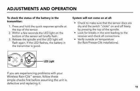
To check the status of the battery in the transmitter:
1. Press and hold the quick response spindle at the top of the sensor.
2. Within a few seconds the LED light on the bottom of the sensor will briefly flash.
3. Release the spindle and the LED light will flash again. If the LED flashes, the battery in the transmitter is good.
If you are experiencing problems with your Wireless Rain-Clik™ sensor, follow these simple checks first before assuming the unit is defective and replacing it.
system will not come on at all:
• Check to make sure that the sensor discs are dry and the switch “clicks” on and off freely by pressing the top of the spindle.
• Look for breaks in the wire leading to the receiver and check all connections.
• Verify outside air temperature (for Rain/Freeze-Clik installations).
LED Light
16
adjusTmenTs and operaTion
system will not shut off even after heavy rainfall:
• Remove the sensor jumper across the two SEN terminals.
• Check to make sure that rainfall is hitting the sensor.
• Look for breaks in the wire leading to the receiver and check all connections.
• Check the battery in the transmitter (See page 15).
sensor bypass led is flashing red:
• Check that the battery in the transmitter is good (See page 15).
• Check for obstructions around the transmitter or receiver antenna.
17
fCC noTiCe
sensor fCC id:m3uWrCe
This device complies with FCC rules Part 15. Operation is subject to the following two conditions:1. This device may not cause harmful interference and2. This device must accept any interference received, including interference that may cause undesired operation.
This equipment has been tested and found to comply with the limits for class B digital devices, pursuant to part 15 of the FCC Rules. These limits are designed to provide reasonable protection against harmful interference in a residential installation. This equipment generates, uses, and can radiate radio frequency energy and if not installed and used in accordance with the instructions, may cause harmful interference to radio communications. However, there is no guarantee that interference will not occur in a particular installation. If this equipment does cause harmful interference to radio or television reception, which can be determined by turning the equipment on and off, the user is encouraged to try to correct the interference by one or more of the following measures:• Reorient or relocate the receiving antenna• Increase the separation between the equipment and the receiver• Connect the equipment to an outlet on a circuit different from that to which the receiver is connected• Consult the dealer or an experienced radio/TV technician for help
The user is cautioned that changes and modifications made to the equipment without the approval of the manufacturer could void the user’s authority to operate this equipment.
18
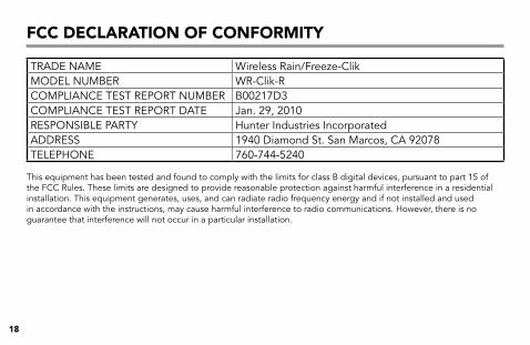
TRADE NAME Wireless Rain/Freeze-ClikMODEL NUMBER WR-Clik-RCOMPLIANCE TEST REPORT NUMBER B00217D3COMPLIANCE TEST REPORT DATE Jan. 29, 2010RESPONSIBLE PARTY Hunter Industries IncorporatedADDRESS 1940 Diamond St. San Marcos, CA 92078TELEPHONE 760-744-5240
This equipment has been tested and found to comply with the limits for class B digital devices, pursuant to part 15 of the FCC Rules. These limits are designed to provide reasonable protection against harmful interference in a residential installation. This equipment generates, uses, and can radiate radio frequency energy and if not installed and used in accordance with the instructions, may cause harmful interference to radio communications. However, there is no guarantee that interference will not occur in a particular installation.
fCC deClaraTion of ConformiTY

19
fCC deClaraTion of ConformiTY
If this equipment does cause harmful interference to radio or television reception, please refer to you user’s manual for instructions on correcting the problem. The undersigned, hereby declare that the equipment specified above conforms to the above requirements.
Signature:
Place: San Marcos, CA Full Name: Peter Woytowitz
Date: March 18, 2010 Position: Engineering Manager
20
indusTrY of Canada noTiCe
Sensor - IC:2772A-WRCE Receiver - IC:2772A-WRCER
Operation is subject to the following two conditions:1. This device may not cause harmful interference and2. This device must accept any interference received, including interference that may cause undesired
operation.

21
Ce & ausTralia noTiCe
Hunter Industries hereby declares that this remote control device is in compliance with the essential requirements and other relevant provisions of Directive 1999/5/CE. Declaration of Conformity: We, Hunter Industries Incorporated, 1940 Diamond Street, San Marcos, CA 92078, declare under our own responsibility that the Wireless Rain/Freeze-Clik, model numbers WR-Clik-TR, WRF-Clik-TR and WR-Clik-R, to which this declaration refers, conforms with the relevant standards:
Emissions: ETSI EN 300 220-1 V2.1.1 ETSI EN 300 220-2 V2.1.1 ETSI EN 301 489-1 (per EN55022) EN 61000-3-2 EN61000-3-3Immunity: ETSI EN 301 489-1 V1.4.1 (per IEC61000-4-2 through IEC61000-4-6, and IEC61000-4-11)
Signature:
Place: San Marcos, CA Full Name: Peter Woytowitz
Date: March 18, 2010 Position: Engineering Manager

22
noTes

23
noTes

hunter industries incorporated • The irrigation innovators © 2011 Hunter Industries Incorporated
1940 Diamond Street • San Marcos, California 92078 USA P/N 715182 23-594 C 02/11
www.hunterindustries.com