Embed Size (px)
Citation preview
Rain Harvesting Tank Package A & B Guidelines for Use & Installation
Rev. 1 January 2009
Phone: 402-467-5221 • Fax: 402-465-1220 Corporate Headquarters: P.O. Box 4583 • Lincoln, Nebraska • 68504
Other Manufacturing Locations: Marked Tree, Arkansas • Mancelona, Michigan • Philippi, West Virginia • Chowchilla, California
Snyder Industries, Inc. Rev 1 - January 2009 1
Table of Contents Package Descriptions 2 Tank Packages 2 Water Diverter Packages 2 Pump Packages 2 Additional Accessories 3 Tanks System Overviews 4
Vertical Tank System w/ Internal Pump Overview 4 Slimline Tank System w/ External Pump Overview 5 Cistern Tank System w/ Internal Pump Overview 6
Installation Instructions 7 Above Ground Tank Package Installation Instruction 7 Below Ground Tank Package Installation Instruction 8 Internal Pump Package Installation Instructions 10 External Pump Package Installation Instructions 12 Cistern Manifold Installation Instructions 14
Snyder Industries, Inc. Rev 1 - January 2009 2
Package Descriptions Tank Packages
Above Ground Tank Package A [simplex part number for each size tank] • SII Tank (300 to 5000 gallons vertical and 400 gallon Slimline) • 18” non-vented threaded manway (15” access) w/ 5” diameter hole • Strainer Basket • 2” Bottom drain fitting • 3” Overflow fitting w/ gasket • 3” Screened overflow adaptor • Rain Harvesting Installation Instructions
Above Ground Tank Package B [simplex part number for each size tank] • Above Ground Tank Package A • Leaf Eater • Water Diverter
o For tanks < 1000 gallons: Water Diverter o For tanks > 1000 gallons: Post Mounted Water Diverter
• External pump w/ pump control • 1” bulkhead fitting Below Ground Cistern Package A [simplex part number for each size tank] • SII Cistern (575 to 1700 gallons) • SII Lid (20” access) w/ (4) SS gasketed screws • SII 12” Riser • 3” Screened cistern vent w/ 3” bulkhead fitting • 4” gasket (to plumb overflow) • 4” Screened overflow adaptor (shipped loose inside of tank) • Rain Harvesting Installation Instructions • Tank Installation Instructions
Below Ground Tank Package B [simplex part number for each size tank] • Below Ground Tank Package A • Leaf Eater • In Ground Water Diverter • Submersible pump • Pump control • 3 Cord Seal • 1” bulkhead fitting *Note: A below ground Filter Pit Kit can be purchased as an option. See Additional Accessories Below.
Snyder Industries, Inc. Rev 1 - January 2009 3
Additional Accessories
Above Ground: • 18” non-vented threaded manway • 1” bulkhead fitting • 1 ½” bulkhead fitting • 2” bulkhead fitting • 3” bulkhead fitting • 2” bolted fitting • 3” bolted fitting Below Ground: • 20” lid • Tamper Resistant screw kit • 2” ¼-14 SS gasketed hex head screw (for lid or riser) • 6” riser • 12” riser • 18” riser • 3” cistern vent • 3” rubber gasket • 4” rubber gasket • 6” rubber gasket • 22” filter pit kit Rainwater: • Leaf Eater • Water Diverter • Post Mounted Water Diverter • In Ground Water Diverter • Strainer Basket • Rain Alert (ultrasonic tank gauge) • Tank Gauge (float tank gauge) • Canale Adaptor • ¾ hp Ecodiver 1000A (submersible pump) • ½ hp Ecotronic 230 (external pump w/pump controls) • Hydrotronic (pump controls) • Filter housing • 20 micron filter • 60 micron filter • 3” overflow fitting • 3” overflow adaptor • 4” overflow adaptor • Pump buddy float valve • External pump cover • Cord seal
*Note: See Pricelist for all part number and ordering information.
Snyder Industries, Inc. Rev 1 - January 2009 4
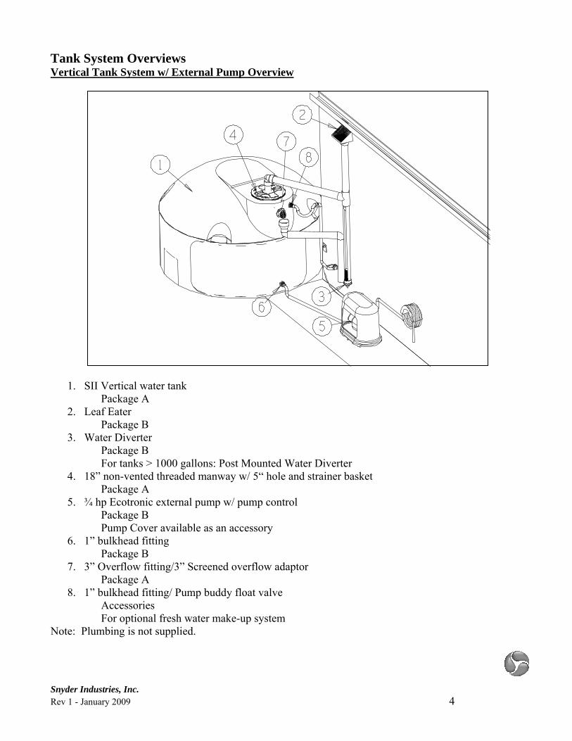
Tank System Overviews Vertical Tank System w/ External Pump Overview
1. SII Vertical water tank Package A
2. Leaf Eater Package B
3. Water Diverter Package B For tanks > 1000 gallons: Post Mounted Water Diverter
4. 18” non-vented threaded manway w/ 5“ hole and strainer basket Package A
5. ¾ hp Ecotronic external pump w/ pump control Package B Pump Cover available as an accessory
6. 1” bulkhead fitting Package B
7. 3” Overflow fitting/3” Screened overflow adaptor Package A
8. 1” bulkhead fitting/ Pump buddy float valve Accessories For optional fresh water make-up system
Note: Plumbing is not supplied.
Snyder Industries, Inc. Rev 1 - January 2009 5
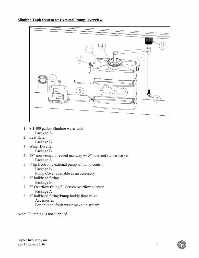
Slimline Tank System w/ External Pump Overview
1. SII 400 gallon Slimline water tank Pacakge A
2. Leaf Eater Package B
3. Water Diverter Package B
4. 18” non-vented threaded manway w/ 5” hole and stainer basket Package A
5. ¾ hp Ecotronic external pump w/ pump control Package B Pump Cover available as an accessory
6. 1” bulkhead fitting Package B
7. 3” Overflow fitting/3” Screen overflow adaptor Package A
8. 1” bulkhead fitting/Pump buddy float valve Accessories For optional fresh water make-up system
Note: Plumbing is not supplied
Snyder Industries, Inc. Rev 1 - January 2009 6
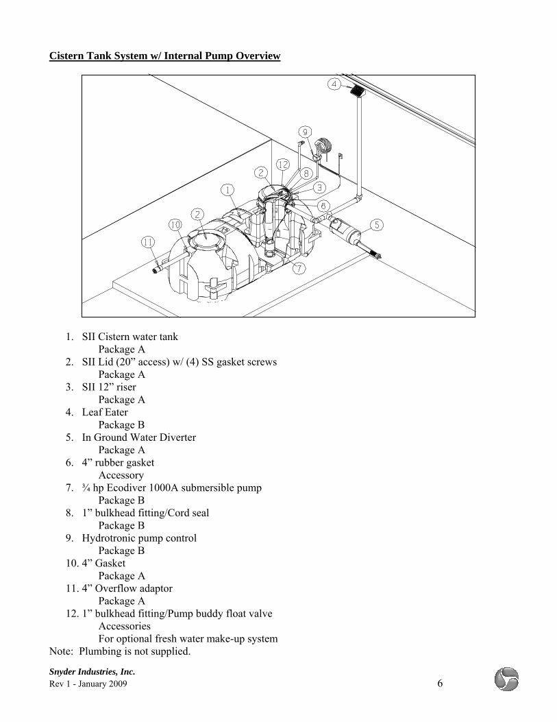
Cistern Tank System w/ Internal Pump Overview
1. SII Cistern water tank
Package A 2. SII Lid (20” access) w/ (4) SS gasket screws
Package A 3. SII 12” riser
Package A 4. Leaf Eater
Package B 5. In Ground Water Diverter
Package A 6. 4” rubber gasket
Accessory 7. ¾ hp Ecodiver 1000A submersible pump
Package B 8. 1” bulkhead fitting/Cord seal
Package B 9. Hydrotronic pump control
Package B 10. 4” Gasket
Package A 11. 4” Overflow adaptor
Package A 12. 1” bulkhead fitting/Pump buddy float valve
Accessories For optional fresh water make-up system
Note: Plumbing is not supplied.
Snyder Industries, Inc. Rev 1 - January 2009 7
Installation Instructions Above Ground Tank Package Installation Instruction
1. Pre-Installation Notes a. Temperature – All SII water tanks are designed for a maximum continuous service
temperature of 100ºF. i. Temperature above 100ºF will reduce the strength of the tank.
ii. Failure to adhere to this criterion will void warranty. b. Pressure – All SII water tanks are designed for use at atmospheric pressure.
i. Positive or negative (vacuum) pressure situations may damage or deform the tank. ii. Failure to adhere to this criterion will void warranty.
c. Location - All SII water tanks are to be placed in a suitable location on a firm base capable of bearing the weight of the tank and its maximum content.
i. Be certain to reference SII’s Guidelines for Use and Installation of Above Ground Water Tanks available at www.snydernet.com.
ii. Failure to adhere to the criteria in the referenced document will void warranty. d. Plumbing – All plumbing to and from the SII water tank must be independently
supported and allow for 4% dimensional movement. i. SII recommends the use of flex hose or expansion joints for all tank connections.
ii. Failure to adhere to this criterion will void warranty. 2. Install Inlet plumbing.
a. Plumb PVC inlet plumbing through 5” hole in manway. i. If utilizing a Water Diverter, install per instructions supplied with Water Diverter
[not supplied in tank package A]. ii. Be certain to allow for 2” air space from the overflow fitting and the bottom of the
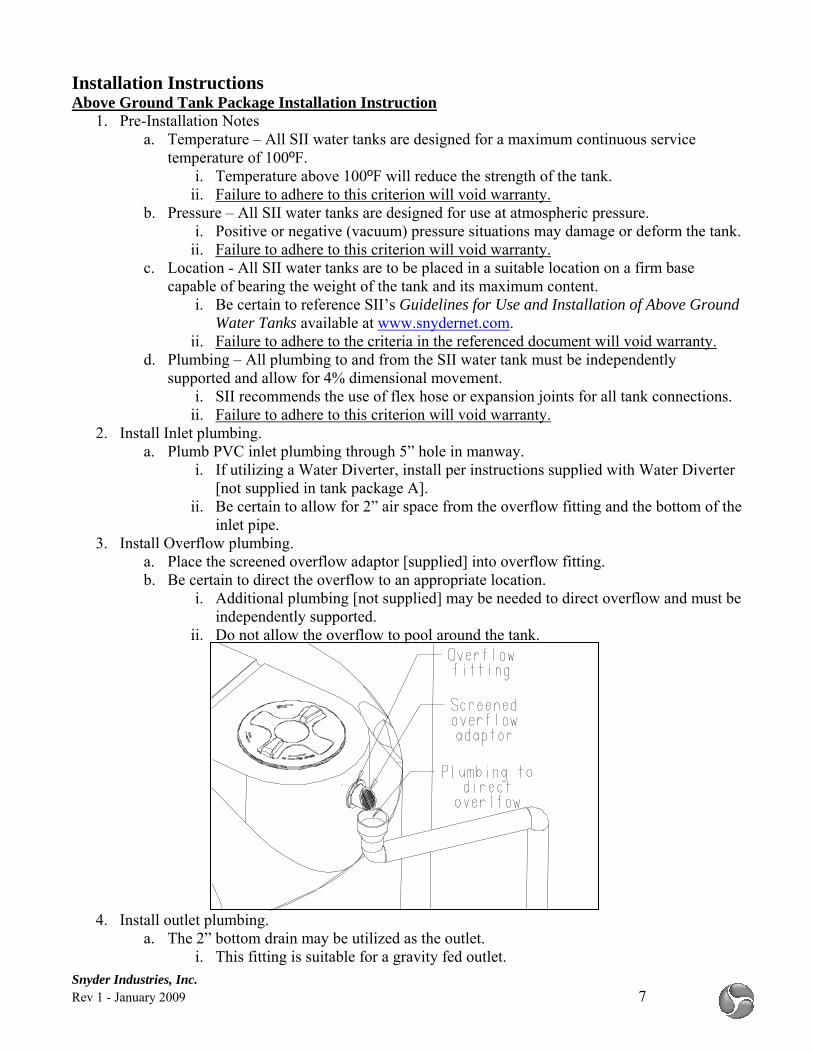
inlet pipe. 3. Install Overflow plumbing.
a. Place the screened overflow adaptor [supplied] into overflow fitting. b. Be certain to direct the overflow to an appropriate location.
i. Additional plumbing [not supplied] may be needed to direct overflow and must be independently supported.
ii. Do not allow the overflow to pool around the tank.
4. Install outlet plumbing.
a. The 2” bottom drain may be utilized as the outlet. i. This fitting is suitable for a gravity fed outlet.
Snyder Industries, Inc. Rev 1 - January 2009 8
ii. This fitting is suitable for a pump [not supplied in tank package A] delivered outlet.
b. Outlet plumbing may be installed in many different locations on the tank. i. Transitions through the wall of the tank must be made with either a bulkhead or
bolted fitting. ii. All plumbing must be independently supported and allow for 4% dimensional
movement. 1. SII recommends the use of flex hose or expansion joints for all tank
connections. Below Ground Tank Package Installation Instruction
1. Pre-Installation Notes a. Temperature – All SII cistern tanks are designed for a maximum continuous service
temperature of 100ºF. i. Temperature above 100ºF will reduce the strength of the tank.
ii. Failure to adhere to this criterion will void warranty. b. Pressure – All SII cistern tanks are designed for use at atmospheric pressure.
i. Positive or negative (vacuum) pressure situations may damage or deform the tank. ii. Failure to adhere to this criterion will void warranty.
c. Location - All SII cistern tanks are to be placed in a suitable location. i. Be certain to reference SII’s Site Selection/Preparation & Septic Do’s and Don’ts
available at www.snydernet.com. ii. Failure to adhere to the criteria in the referenced document will void warranty.
d. Installation – All SII Cistern tanks are to be installed in strict accordance to SII’s installation instructions.
i. Be certain to read and follow SII’s NuConSept Low Profile Cistern Tank Installation Procedures [99800014] available at www.snydernet.com.
e. Plumbing - All plumbing to and from the SII water tank must be independently supported and allow for 4% dimensional movement.
i. SII recommends the use of flex hose or expansion joints for all tank connections. ii. Failure to adhere to this criterion will void warranty.
2. Install cistern. a. Following SII’s NuConSept Low Profile Cistern Tank Installation Procedures
[99800014] sections 1-3, place the tank into the excavation and attach the 12” riser [supplied].
b. Be certain that credence is paid to locating the tank, proper bedding of the tank, managing any sources of water runoff, and the maximum 36” burial depth.
3. Install inlet plumbing prior to completing section 4 of SII’s NuConSept Low Profile Cistern Tank Installation Procedures [99800014].
a. If utilizing Filter Pit [not supplied in tank package A] or In Ground Water Diverter install per instructions supplied with Filter Pit or In Ground Water Diverter [not supplied in tank package A].
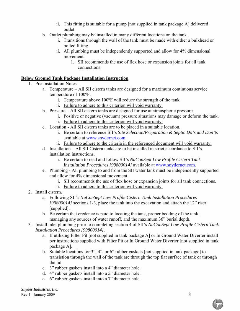
b. Suitable locations for 3”, 4”, or 6” rubber gaskets [not supplied in tank package] to transistion through the wall of the tank are through the top flat surface of tank or through the lid.
c. 3” rubber gaskets install into a 4” diameter hole. d. 4” rubber gaskets install into a 5” diameter hole. e. 6” rubber gaskets install into a 7” diameter hole.
Snyder Industries, Inc. Rev 1 - January 2009 9
f. Be certain to allow for 2” air space from the invert of the overflow fitting and the bottom
of the inlet pipe. g. Complete the rest of the inlet plumbing [not supplied].
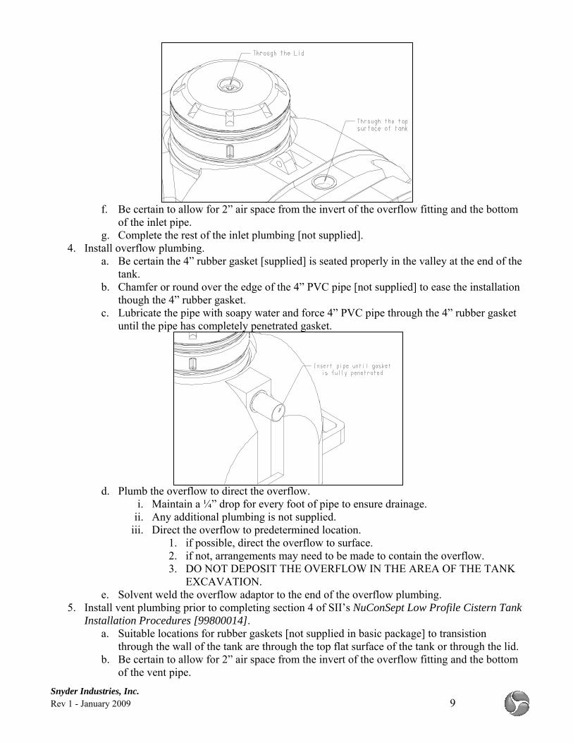
4. Install overflow plumbing. a. Be certain the 4” rubber gasket [supplied] is seated properly in the valley at the end of the
tank. b. Chamfer or round over the edge of the 4” PVC pipe [not supplied] to ease the installation
though the 4” rubber gasket. c. Lubricate the pipe with soapy water and force 4” PVC pipe through the 4” rubber gasket
until the pipe has completely penetrated gasket.
d. Plumb the overflow to direct the overflow.
i. Maintain a ¼” drop for every foot of pipe to ensure drainage. ii. Any additional plumbing is not supplied.
iii. Direct the overflow to predetermined location. 1. if possible, direct the overflow to surface. 2. if not, arrangements may need to be made to contain the overflow. 3. DO NOT DEPOSIT THE OVERFLOW IN THE AREA OF THE TANK
EXCAVATION. e. Solvent weld the overflow adaptor to the end of the overflow plumbing.
5. Install vent plumbing prior to completing section 4 of SII’s NuConSept Low Profile Cistern Tank Installation Procedures [99800014].
a. Suitable locations for rubber gaskets [not supplied in basic package] to transistion through the wall of the tank are through the top flat surface of the tank or through the lid.
b. Be certain to allow for 2” air space from the invert of the overflow fitting and the bottom of the vent pipe.
Snyder Industries, Inc. Rev 1 - January 2009 10
6. Install outlet plumbing prior to completing section 4 of SII’s NuConSept Low Profile Cistern Tank Installation Procedures [99800014].
a. Outlet plumbing may be installed in many different locations on the tank. i. Transitions through the wall of the tank or riser must be made with either a
bulkhead fitting, bolted fitting, or rubber gasket (if transition is completely above water level).
ii. All plumbing must be independently supported and allow for 4% dimensional movement.
1. SII recommends the use of flex hose or expansion joints for all tank connections.
7. SII recommends partially filling the tank with water to test the system prior to backfilling the tank.
8. Complete the installation of the tank per SII’s NuConSept Low Profile Cistern Tank Installation Procedures [99800014].
a. Clean, free-flowing, debris-free soil may be used as backfill material. i. Failure to adhere to this criterion will void warranty.
b. Backfill material containing any clay will void warranty. c. Mound over the excavation to create positive drainage away for the tank installation.
Internal Pump Package Installation Instructions
1. Determine the location for the exit for the pump line out of the tank. a. For above ground tanks, SII recommends exiting the tank through the sidewall of the
tank. b. For below ground tanks SII recommends exiting the tank through the riser.
2. Install a 1” bulkhead [supplied] fitting to transition from inside to outside of the tank. a. Locations for 1” bulkhead fittings must follow the following rules
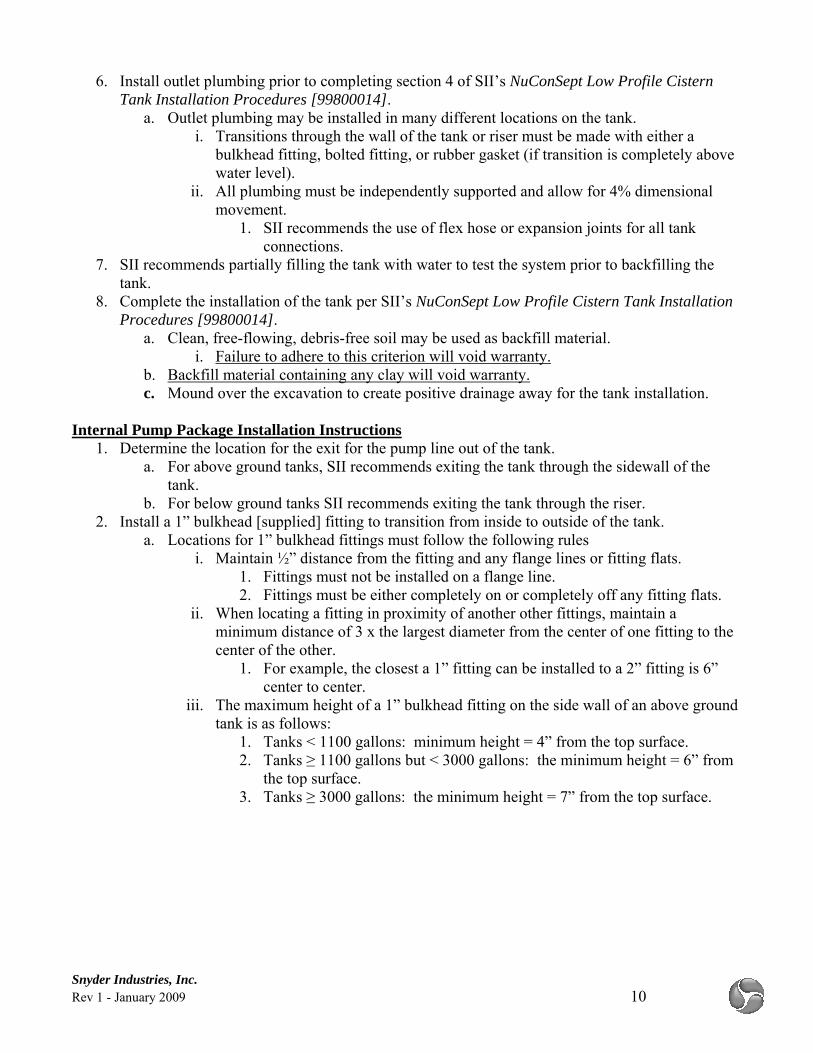
i. Maintain ½” distance from the fitting and any flange lines or fitting flats. 1. Fittings must not be installed on a flange line. 2. Fittings must be either completely on or completely off any fitting flats.
ii. When locating a fitting in proximity of another other fittings, maintain a minimum distance of 3 x the largest diameter from the center of one fitting to the center of the other.
1. For example, the closest a 1” fitting can be installed to a 2” fitting is 6” center to center.
iii. The maximum height of a 1” bulkhead fitting on the side wall of an above ground tank is as follows:
1. Tanks < 1100 gallons: minimum height = 4” from the top surface. 2. Tanks ≥ 1100 gallons but < 3000 gallons: the minimum height = 6” from
the top surface. 3. Tanks ≥ 3000 gallons: the minimum height = 7” from the top surface.
Snyder Industries, Inc. Rev 1 - January 2009 11
b. Install 1” bulkhead fitting. i. Using a 2 ¼” hole saw cut a hole at the location of the fitting.
ii. De-burr the hole iii. From the inside of the tank, remove the nut from the fitting neck and place fitting
neck through the hole with the gasket between inside wall of the tank and the flange of the fitting neck.
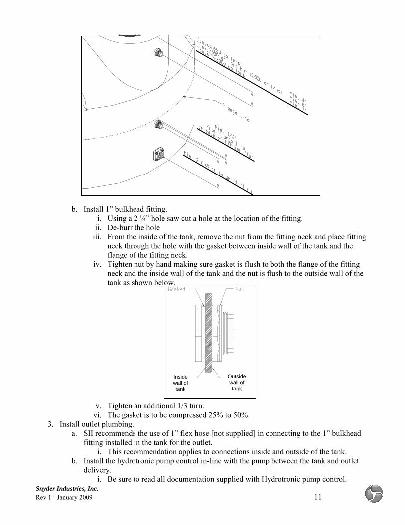
iv. Tighten nut by hand making sure gasket is flush to both the flange of the fitting neck and the inside wall of the tank and the nut is flush to the outside wall of the tank as shown below.
v. Tighten an additional 1/3 turn. vi. The gasket is to be compressed 25% to 50%.
3. Install outlet plumbing. a. SII recommends the use of 1” flex hose [not supplied] in connecting to the 1” bulkhead
fitting installed in the tank for the outlet. i. This recommendation applies to connections inside and outside of the tank.
b. Install the hydrotronic pump control in-line with the pump between the tank and outlet delivery.
i. Be sure to read all documentation supplied with Hydrotronic pump control.
Outside wall of tank
Inside wall of tank
Snyder Industries, Inc. Rev 1 - January 2009 12
ii. Be sure to locate the hydrotronic pump control in an accessible yet protected location.
4. Install pump. a. Read all documentation supplied with pump. b. Place the submersible pump at the bottom of the tank. c. Connect the pump to the flex hose connected to the 1” bulkhead fitting inside of the tank. d. Connect the power cord from the pump to the hydrotronic pump control.
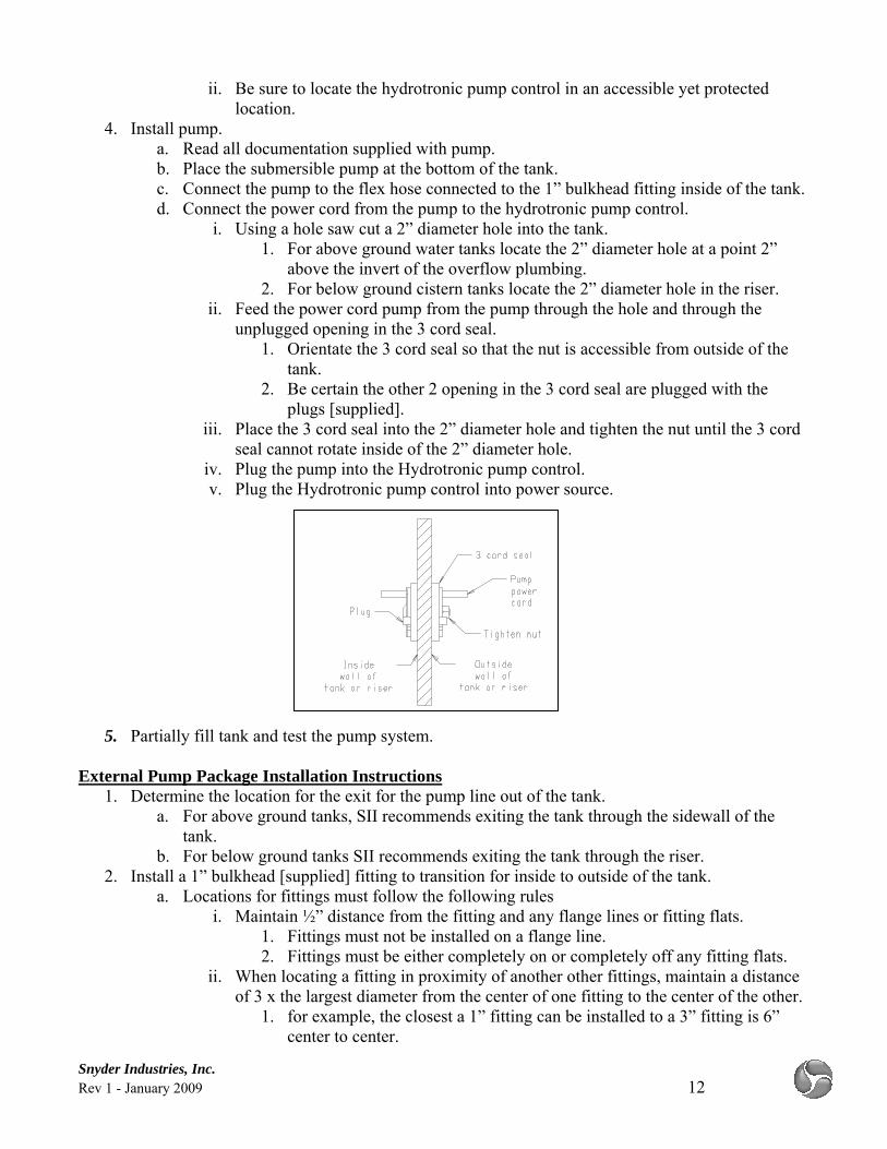
i. Using a hole saw cut a 2” diameter hole into the tank. 1. For above ground water tanks locate the 2” diameter hole at a point 2”
above the invert of the overflow plumbing. 2. For below ground cistern tanks locate the 2” diameter hole in the riser.
ii. Feed the power cord pump from the pump through the hole and through the unplugged opening in the 3 cord seal.
1. Orientate the 3 cord seal so that the nut is accessible from outside of the tank.
2. Be certain the other 2 opening in the 3 cord seal are plugged with the plugs [supplied].
iii. Place the 3 cord seal into the 2” diameter hole and tighten the nut until the 3 cord seal cannot rotate inside of the 2” diameter hole.
iv. Plug the pump into the Hydrotronic pump control. v. Plug the Hydrotronic pump control into power source.
5. Partially fill tank and test the pump system. External Pump Package Installation Instructions
1. Determine the location for the exit for the pump line out of the tank. a. For above ground tanks, SII recommends exiting the tank through the sidewall of the
tank. b. For below ground tanks SII recommends exiting the tank through the riser.
2. Install a 1” bulkhead [supplied] fitting to transition for inside to outside of the tank. a. Locations for fittings must follow the following rules
i. Maintain ½” distance from the fitting and any flange lines or fitting flats. 1. Fittings must not be installed on a flange line. 2. Fittings must be either completely on or completely off any fitting flats.
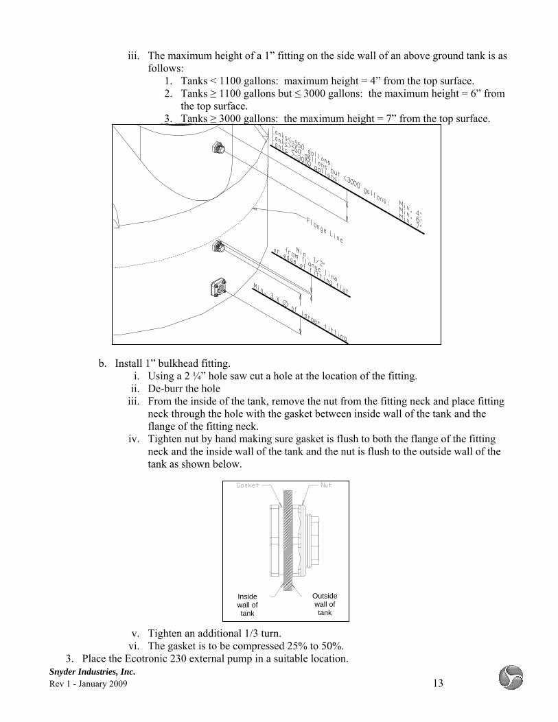
ii. When locating a fitting in proximity of another other fittings, maintain a distance of 3 x the largest diameter from the center of one fitting to the center of the other.
1. for example, the closest a 1” fitting can be installed to a 3” fitting is 6” center to center.
Snyder Industries, Inc. Rev 1 - January 2009 13
iii. The maximum height of a 1” fitting on the side wall of an above ground tank is as follows:
1. Tanks < 1100 gallons: maximum height = 4” from the top surface. 2. Tanks ≥ 1100 gallons but ≤ 3000 gallons: the maximum height = 6” from
the top surface. 3. Tanks ≥ 3000 gallons: the maximum height = 7” from the top surface.
b. Install 1” bulkhead fitting. i. Using a 2 ¼” hole saw cut a hole at the location of the fitting.
ii. De-burr the hole iii. From the inside of the tank, remove the nut from the fitting neck and place fitting
neck through the hole with the gasket between inside wall of the tank and the flange of the fitting neck.
iv. Tighten nut by hand making sure gasket is flush to both the flange of the fitting neck and the inside wall of the tank and the nut is flush to the outside wall of the tank as shown below.
v. Tighten an additional 1/3 turn. vi. The gasket is to be compressed 25% to 50%.
3. Place the Ecotronic 230 external pump in a suitable location.
Outside wall of tank
Inside wall of tank
Snyder Industries, Inc. Rev 1 - January 2009 14
a. Read all documentation supplied with pump. b. Raise the pump slightly off the ground. c. Place pump cover over the pump.
4. Install outlet plumbing. a. Install plumbing [not supplied] from the 1” bulkhead fitting to no closer than 4” from the
bottom of the tank b. Install plumbing [not supplied] from the tank to the external pump.
5. Connect pump to outlet delivery. 6. Connect Pump to Hydrotonic and the Hydrotronic to power source. 7. Partially fill tank and test pump system.
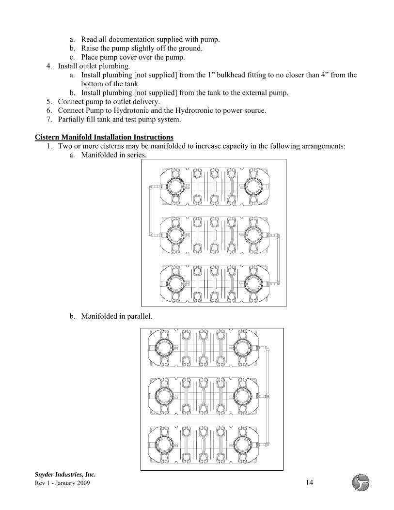
Cistern Manifold Installation Instructions 1. Two or more cisterns may be manifolded to increase capacity in the following arrangements:
a. Manifolded in series.
b. Manifolded in parallel.
Snyder Industries, Inc. Rev 1 - January 2009 15
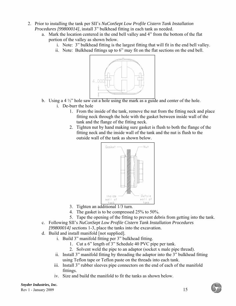
2. Prior to installing the tank per SII’s NuConSept Low Profile Cistern Tank Installation Procedures [99800014], install 3” bulkhead fitting in each tank as needed.
a. Mark the location centered in the end bell valley and 4” from the bottom of the flat portion of the valley as shown below.
i. Note: 3” bulkhead fitting is the largest fitting that will fit in the end bell valley. ii. Note: Bulkhead fittings up to 6” may fit on the flat sections on the end bell.
b. Using a 4 ½” hole saw cut a hole using the mark as a guide and center of the hole.
i. De-burr the hole 1. From the inside of the tank, remove the nut from the fitting neck and place
fitting neck through the hole with the gasket between inside wall of the tank and the flange of the fitting neck.
2. Tighten nut by hand making sure gasket is flush to both the flange of the fitting neck and the inside wall of the tank and the nut is flush to the outside wall of the tank as shown below.
3. Tighten an additional 1/3 turn. 4. The gasket is to be compressed 25% to 50%. 5. Tape the opening of the fitting to prevent debris from getting into the tank.
c. Following SII’s NuConSept Low Profile Cistern Tank Installation Procedures [99800014] sections 1-3, place the tanks into the excavation.
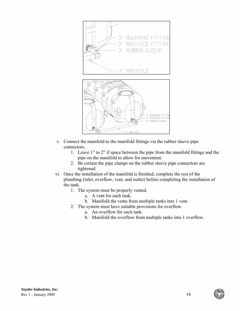
d. Build and install manifold [not supplied]. i. Build 3” manifold fitting per 3” bulkhead fitting.
1. Cut a 6” length of 3” Schedule 40 PVC pipe per tank. 2. Solvent weld the pipe to an adaptor (socket x male pipe thread).
ii. Install 3” manifold fitting by threading the adaptor into the 3” bulkhead fitting using Teflon tape or Teflon paste on the threads into each tank.
iii. Install 3” rubber sleeves pipe connectors on the end of each of the manifold fittings.
iv. Size and build the manifold to fit the tanks as shown below.
Snyder Industries, Inc. Rev 1 - January 2009 16
v. Connect the manifold to the manifold fittings via the rubber sleeve pipe connectors.
1. Leave 1” to 2” if space between the pipe from the manifold fittings and the pipe on the manifold to allow for movement.
2. Be certain the pipe clamps on the rubber sleeve pipe connectors are tightened.
vi. Once the installation of the manifold is finished, complete the rest of the plumbing (inlet, overflow, vent, and outlet) before completing the installation of the tank.
1. The system must be properly vented. a. A vent for each tank. b. Manifold the vents from multiple tanks into 1 vent.
2. The system must have suitable provisions for overflow. a. An overflow for each tank. b. Manifold the overflow from multiple tanks into 1 overflow.