Embed Size (px)
DESCRIPTION
Railways, Rails
Citation preview
7/21/2019 Railways, Rails
http://slidepdf.com/reader/full/railways-rails 1/77
Rails
• Rails provide a smooth path for the
movement of trains at high speed.1
7/21/2019 Railways, Rails
http://slidepdf.com/reader/full/railways-rails 2/77
Functions of Rails
• The rails provide a level, smooth andcontinuous surface for the movement oftrains.
• The friction between the wheels of thetrain and the rail is about 20% of thefriction between the pneumatic tyres andthe roads.
• The rail serves as a lateral guide for therunning of wheels.
2
7/21/2019 Railways, Rails
http://slidepdf.com/reader/full/railways-rails 3/77
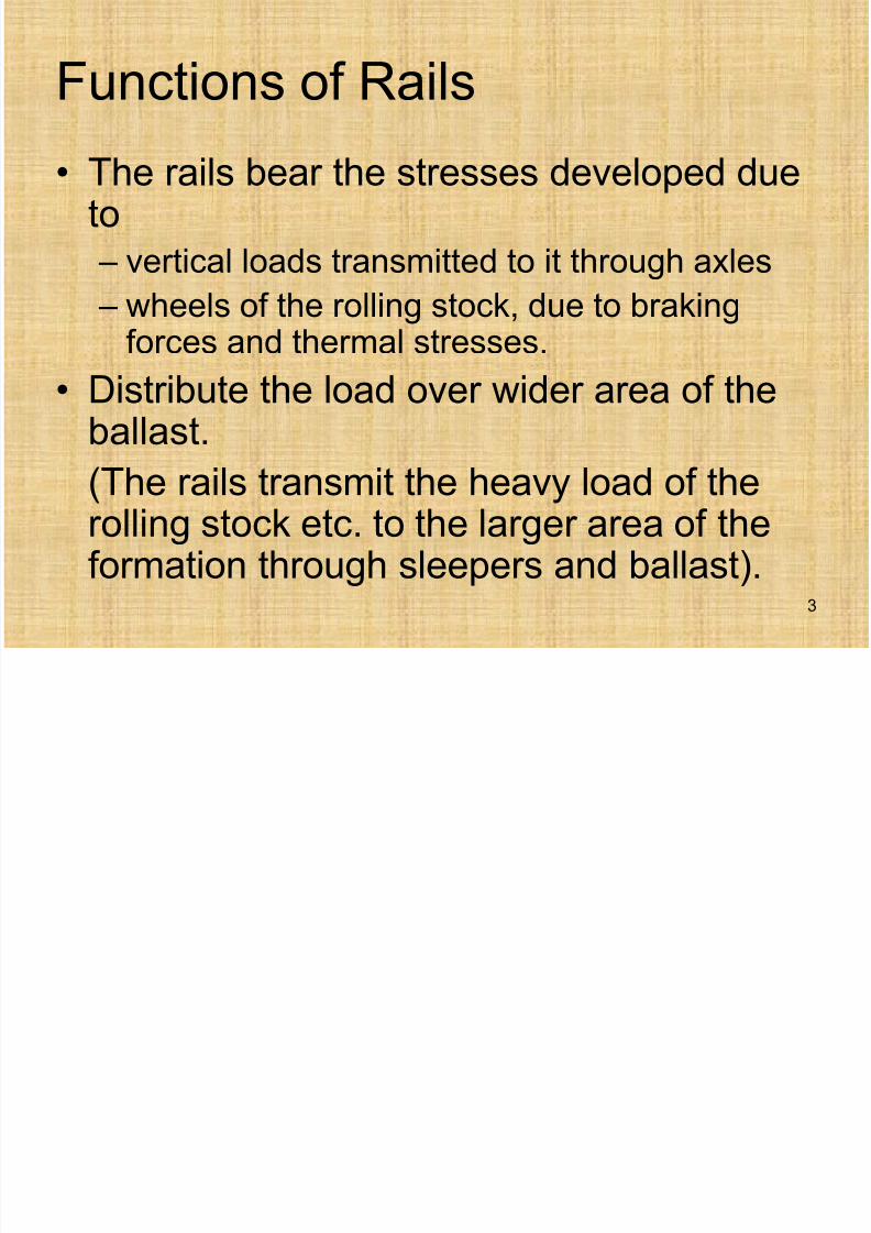
Functions of Rails
• The rails bear the stresses developed dueto
– vertical loads transmitted to it through axles
– wheels of the rolling stock, due to brakingforces and thermal stresses.
• Distribute the load over wider area of theballast.
(The rails transmit the heavy load of therolling stock etc. to the larger area of theformation through sleepers and ballast).
3
7/21/2019 Railways, Rails
http://slidepdf.com/reader/full/railways-rails 4/77
Types of Rail Section
• Double Headed
• Bull Headed
• Flat Footed
4
7/21/2019 Railways, Rails
http://slidepdf.com/reader/full/railways-rails 5/77
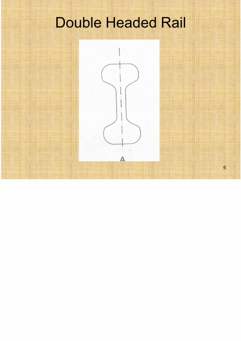
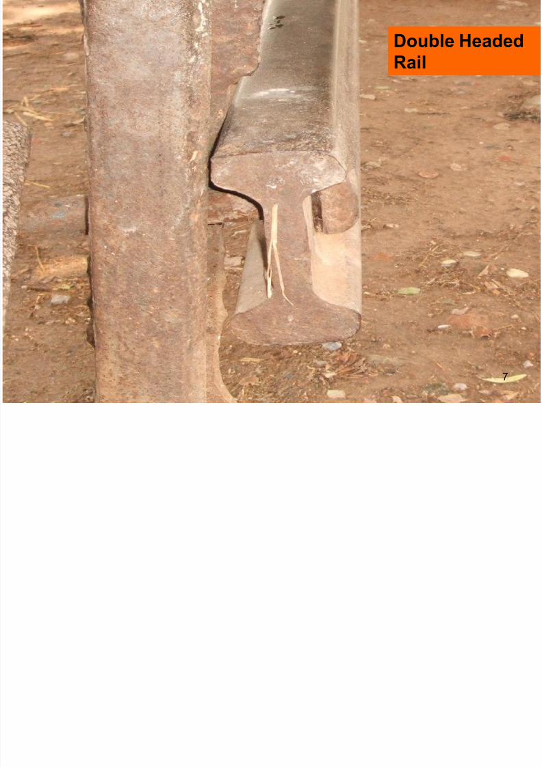
Double Headed Rail:
• The original rails used were double headed
made of I section or dumb-bell section.
• The idea being that when the top of the double
headed rail was worn, the rail could be invertedand re-used.
• Such rails are supported in chairs, which rest on
sleepers.
• It was found that the lower head was dented by
the chairs and could not be re-used effectively.
5
7/21/2019 Railways, Rails
http://slidepdf.com/reader/full/railways-rails 6/77
Double Headed Rail
6
7/21/2019 Railways, Rails
http://slidepdf.com/reader/full/railways-rails 7/77
Double Headed
Rail
7
7/21/2019 Railways, Rails
http://slidepdf.com/reader/full/railways-rails 8/77
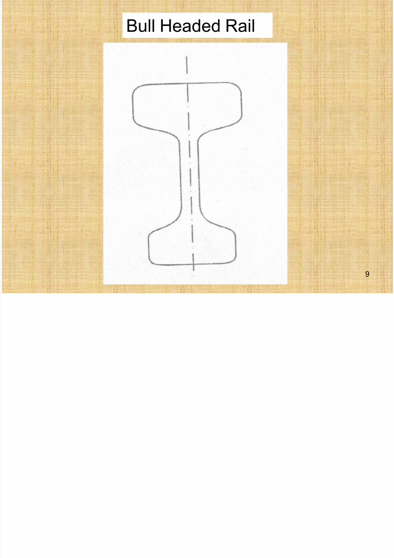
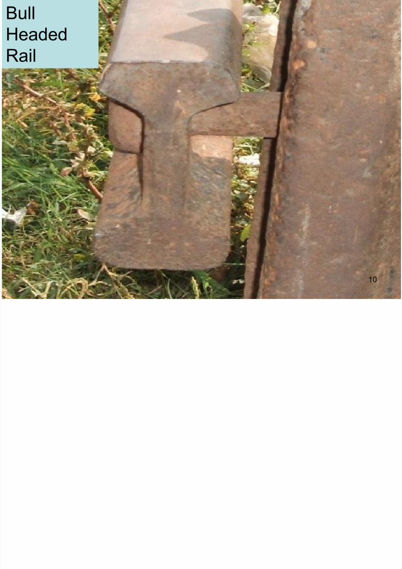
Bull Headed Rail:
• The bull headed rails have more metal
mass added to the head, which permits
more resistance to wear.
• The lower face was of sufficient size to be
able to bear the stresses, which are
induced in it by the moving loads.
8
7/21/2019 Railways, Rails
http://slidepdf.com/reader/full/railways-rails 9/77
Bull Headed Rail
9
7/21/2019 Railways, Rails
http://slidepdf.com/reader/full/railways-rails 10/77
Bull
Headed
Rail
10
7/21/2019 Railways, Rails
http://slidepdf.com/reader/full/railways-rails 11/77
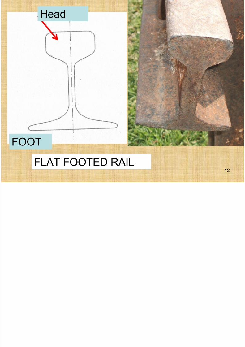
Flat Footed Rail
• A flat footed rail is of an inverted T shape.
• The advantage of these rails lies in the
fact that they are stronger than the bull
headed rails and no chairs are necessary
and the foot of the rail is spiked directly to
the sleeper.
11
7/21/2019 Railways, Rails
http://slidepdf.com/reader/full/railways-rails 12/77
FLAT FOOTED RAIL
Head
FOOT
12
C i f Fl F d d B ll H d d
7/21/2019 Railways, Rails
http://slidepdf.com/reader/full/railways-rails 13/77
Comparison of Flat Footed and Bull Headed
Rail Sections
• B.H. rail keeps better alignment of the
track than the F.F. rail.
• F.F. rails provide more lateral stability than
the B.H. rails.
• F.F. rails are less costly.
• Flat footed rails are easier to lay andrequire less number of fastenings.
13
7/21/2019 Railways, Rails
http://slidepdf.com/reader/full/railways-rails 14/77
Comparison of Flat Footed and Bull Headed
Rail Sections (cont’d)
• Maintenance of F.F. rail is easier.
• The fastenings attached with the F.F. rails
have a greater tendency than the B.H.rails to get loose, particularly if they are
laid on wooden sleepers.
14
7/21/2019 Railways, Rails
http://slidepdf.com/reader/full/railways-rails 15/77
Weight of the Rail Sections
A rail is designated by its weight per yard.
Thus, a 90 lb. rail is a rail weighing 90 lb.
per yard of its length.Weight of the rail is governed by
• Axle loads
• Gauge of the track• Maximum speed which is permitted
• Sleeper Density15
7/21/2019 Railways, Rails
http://slidepdf.com/reader/full/railways-rails 16/77
Weight of the Rail Sections
• As a rule on a BG track, a rail may beexpected to carry an axle load 560 timesthe weight of the rail per yard.
• Heavier sections proved to be economicalin the long run as it has longer life and lessmaintenance.
• Stability of heavier sections will be moreand chances of buckling of the tracks areless.
16
7/21/2019 Railways, Rails
http://slidepdf.com/reader/full/railways-rails 17/77
Weight of the Rail Sections
• Heavier sections result in smooth riding.
• When a loaded wheel moves over the rail,
it depresses the rail and if the rail is light in
weight then it has to bear that greater load
in the depression. The wheel has to be
dragged continuously on such depression
and as a result power of locomotive iswasted.
17
7/21/2019 Railways, Rails
http://slidepdf.com/reader/full/railways-rails 18/77
Length of Rail
• As the rail joint is the weakest part of thetrack structure, its strength is about onehalf that of rails. So it is desirable to use
as long rails as possible.• Wear and tear of vehicles decrease and
comfort of the passengers increases byusing the longer rails (as the number ofblows experienced at the joints by amoving vehicle are diminished).
18
7/21/2019 Railways, Rails
http://slidepdf.com/reader/full/railways-rails 19/77
Length of Rail
The length of the rail is however governed by
• Lengths, which can be produced at reasonable
cost by the manufacturer.
• Handling
• Transportation
• If a defect is found in a rail, a much longer length
has to be wasted in renewal than in case ofshort rails.
19
7/21/2019 Railways, Rails
http://slidepdf.com/reader/full/railways-rails 20/77
Length of Rail
• In Pakistan, the length of the rail used is20 ft. – 42 ft.
• The standard lengths of rails are 42 ft. for
BG and 39 ft. for MG track.• The shortest length of the rail, which may
be used in the track is that which is not
shorter than the longest wheel base of thewagon i.e., the distance between twoadjacent axles which is 12 ft. (generally).
20
7/21/2019 Railways, Rails
http://slidepdf.com/reader/full/railways-rails 21/77
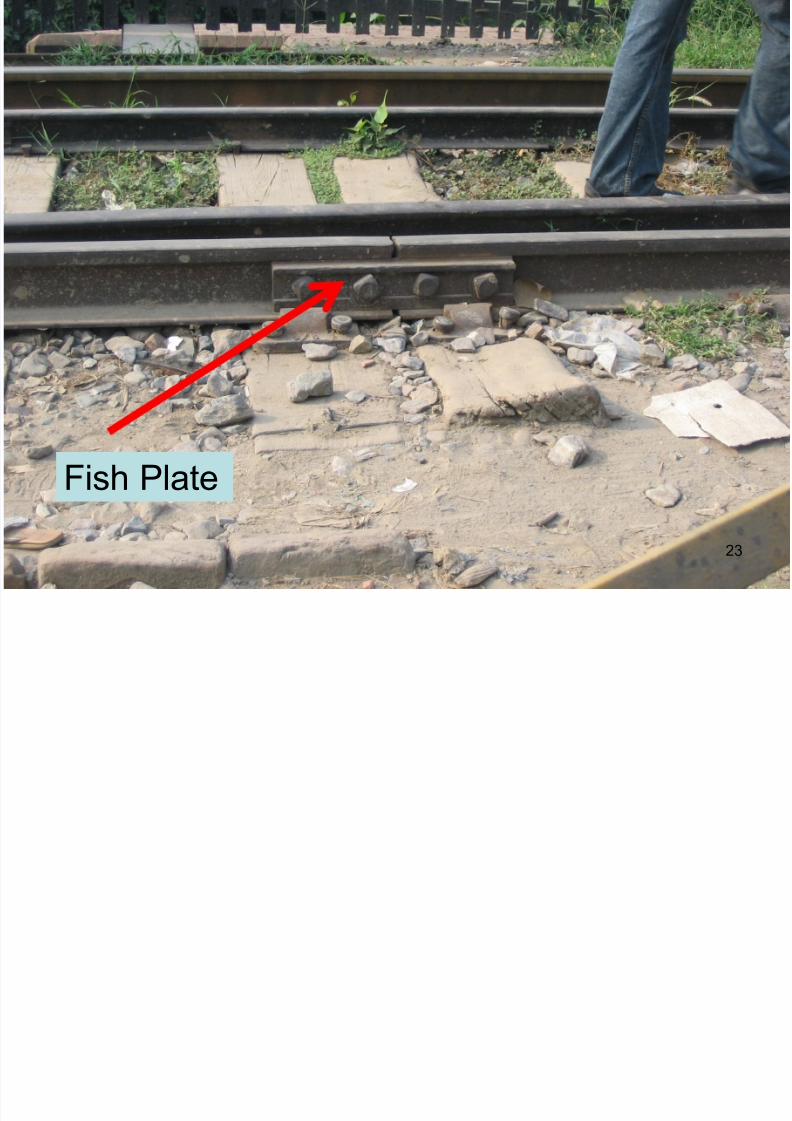
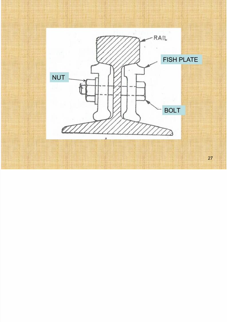
Fish Plates
• The function of a fish plate is to hold tworails together accurately, evenly and firmlyin place with reference to surface and
alignment.• It absorbs the blows which the ends of
rails receive when the wheels negotiatethe gap at the joints.
• The material used for making the fishplates is same as that of rails.
21
7/21/2019 Railways, Rails
http://slidepdf.com/reader/full/railways-rails 22/77
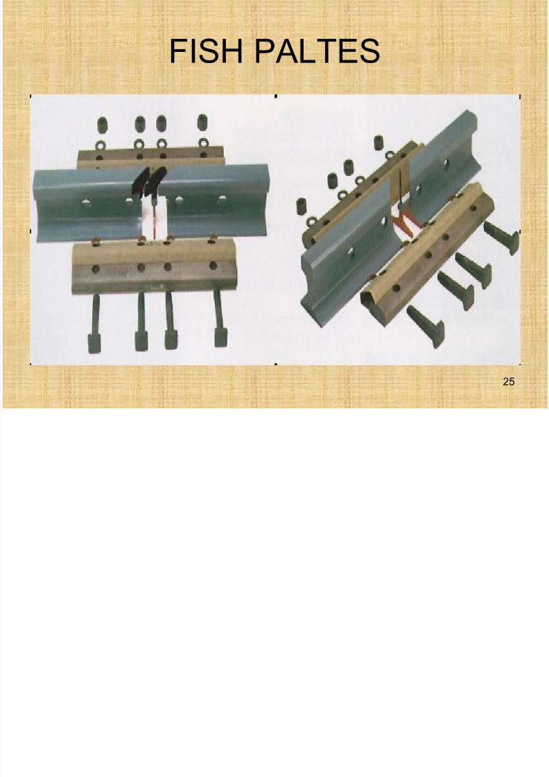
Fish Plates
• The shape of the fish plates is such thatthey fit under the side of rail head and on
top of rail foot.
• Fish plates are designed such that theygive maximum support to the rail ends and
also allow the free expansion and
contraction of the rails.• For this reason the contact surfaces of the
fish plates and the rails are cleaned and
lubricated.22
7/21/2019 Railways, Rails
http://slidepdf.com/reader/full/railways-rails 23/77
Fish Plate
23
7/21/2019 Railways, Rails
http://slidepdf.com/reader/full/railways-rails 24/77
7/21/2019 Railways, Rails
http://slidepdf.com/reader/full/railways-rails 25/77
FISH PALTES
25
7/21/2019 Railways, Rails
http://slidepdf.com/reader/full/railways-rails 26/77
Requirements for Fish Plate
• It should hold the two rails at the samelevel and in the same straight line.
• It should permit easy change of rail
whenever this may be necessary.• It should as far as possible has same
strength and same stiffness as that of rail.
• Their shape should be such that freemovement of rail for expansion orcontraction should not be stopped.
26
7/21/2019 Railways, Rails
http://slidepdf.com/reader/full/railways-rails 27/77
27
FISH PLATE
BOLT
NUT
7/21/2019 Railways, Rails
http://slidepdf.com/reader/full/railways-rails 28/77
Types of Joints
• w.r.t position of joints on track
• w.r.t position of sleepers
Types of joints w.r.t position of joints ontrack
• Square Joints
• Staggered Joints
28
7/21/2019 Railways, Rails
http://slidepdf.com/reader/full/railways-rails 29/77
Square Joint
• When the joint in one rail is exactly
opposite to the joint in the other parallel
rail, it is called square joint.
• It is common in straight tracks.
• On curves, the centrifugal force, tend to
push the track out and at the joint effect is
more, resulting in the formation of kinks.
29
7/21/2019 Railways, Rails
http://slidepdf.com/reader/full/railways-rails 30/77
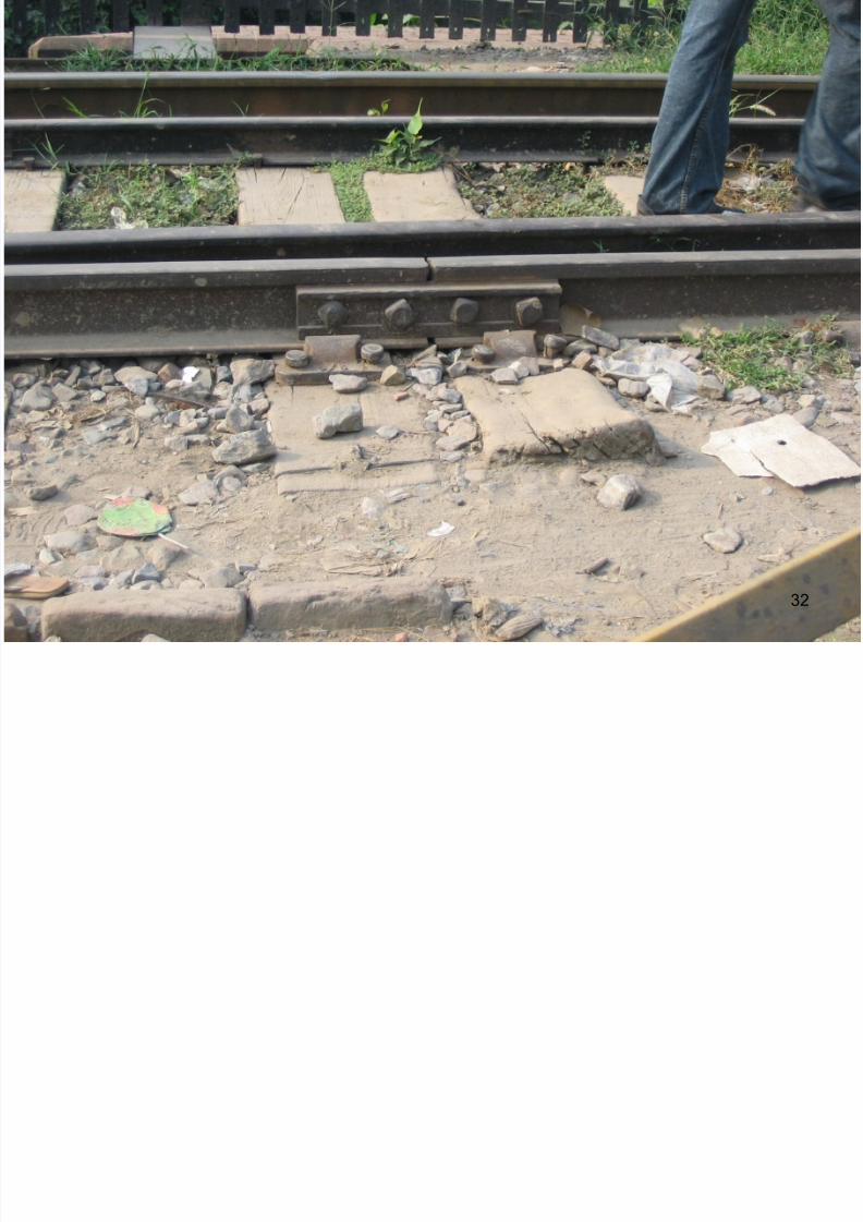
Staggered Joint
• When joint in one rail is not exactlyopposite to the joint of the other parallelrail, then it is called staggered joint. The
joint of one rail is kept facing the center ofthe opposite rail.
• With staggered joints, the number ofhammer blows at the joints are doubledbut the intensity is halved.
. 30
7/21/2019 Railways, Rails
http://slidepdf.com/reader/full/railways-rails 31/77
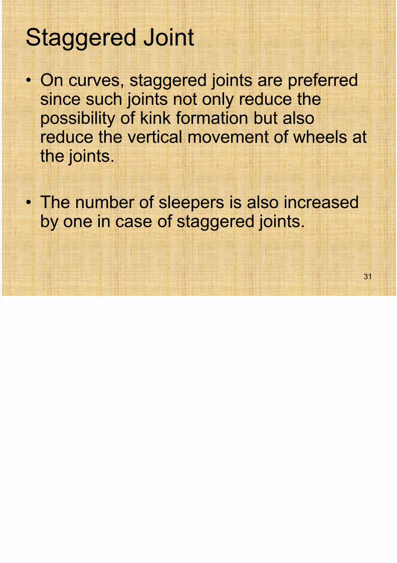
Staggered Joint
• On curves, staggered joints are preferredsince such joints not only reduce thepossibility of kink formation but also
reduce the vertical movement of wheels atthe joints.
• The number of sleepers is also increasedby one in case of staggered joints.
31
7/21/2019 Railways, Rails
http://slidepdf.com/reader/full/railways-rails 32/77
32
7/21/2019 Railways, Rails
http://slidepdf.com/reader/full/railways-rails 33/77
Types of Joints w.r.t position of Sleepers
• Supported Joints
• Suspended Joints• Bridge Joints
33
7/21/2019 Railways, Rails
http://slidepdf.com/reader/full/railways-rails 34/77
7/21/2019 Railways, Rails
http://slidepdf.com/reader/full/railways-rails 35/77
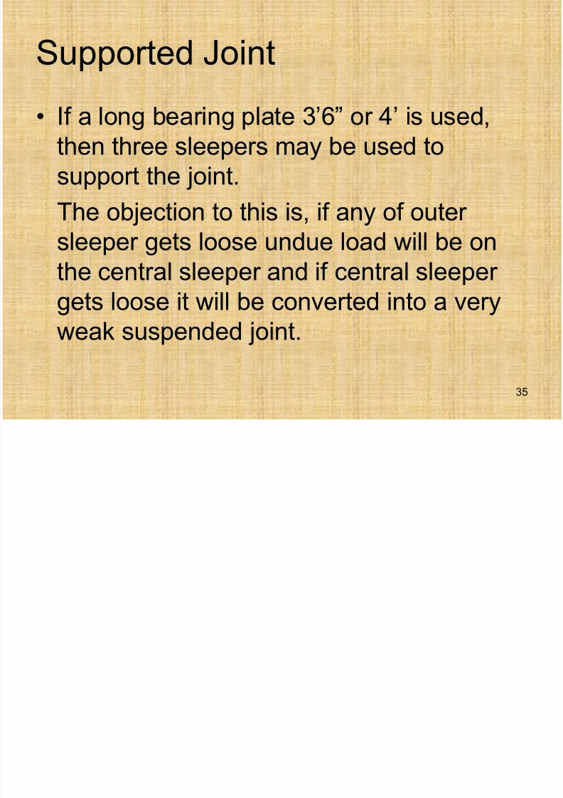
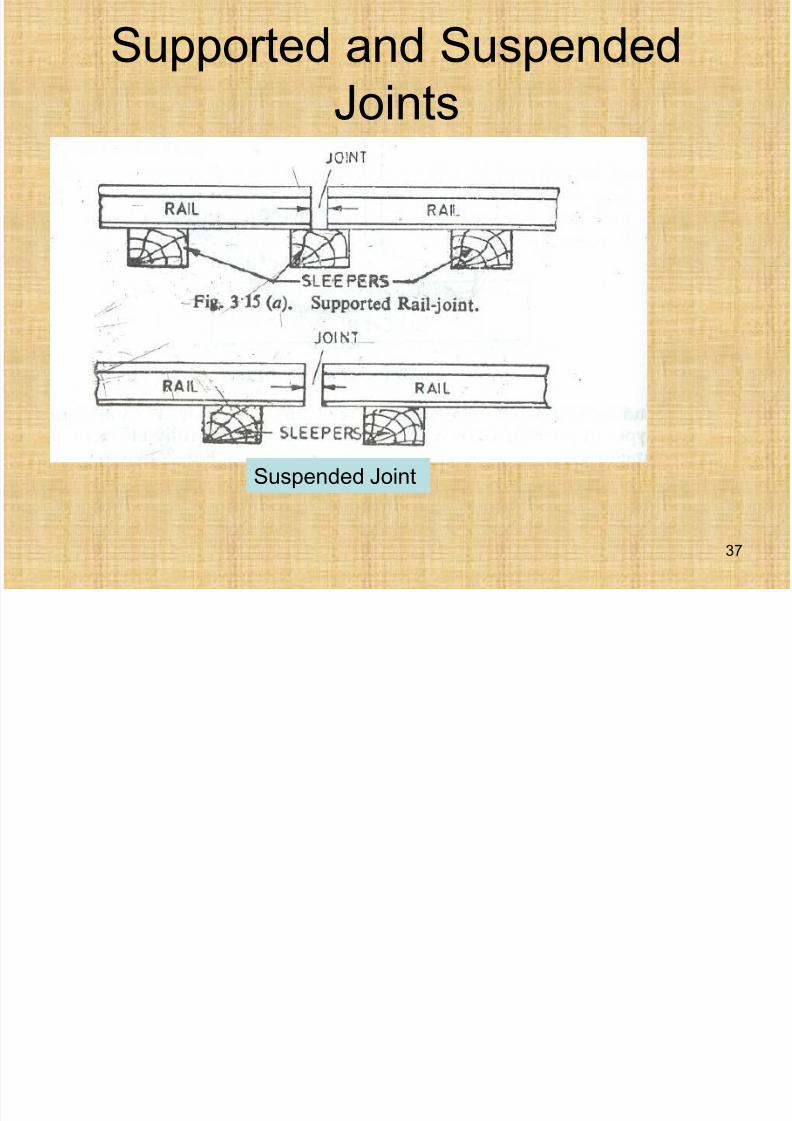
Supported Joint
• If a long bearing plate 3’6” or 4’ is used,
then three sleepers may be used to
support the joint.
The objection to this is, if any of outer
sleeper gets loose undue load will be on
the central sleeper and if central sleeper
gets loose it will be converted into a veryweak suspended joint.
35
7/21/2019 Railways, Rails
http://slidepdf.com/reader/full/railways-rails 36/77
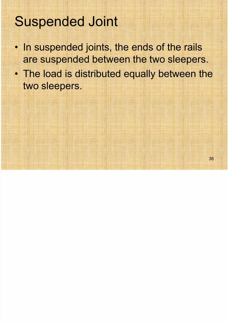
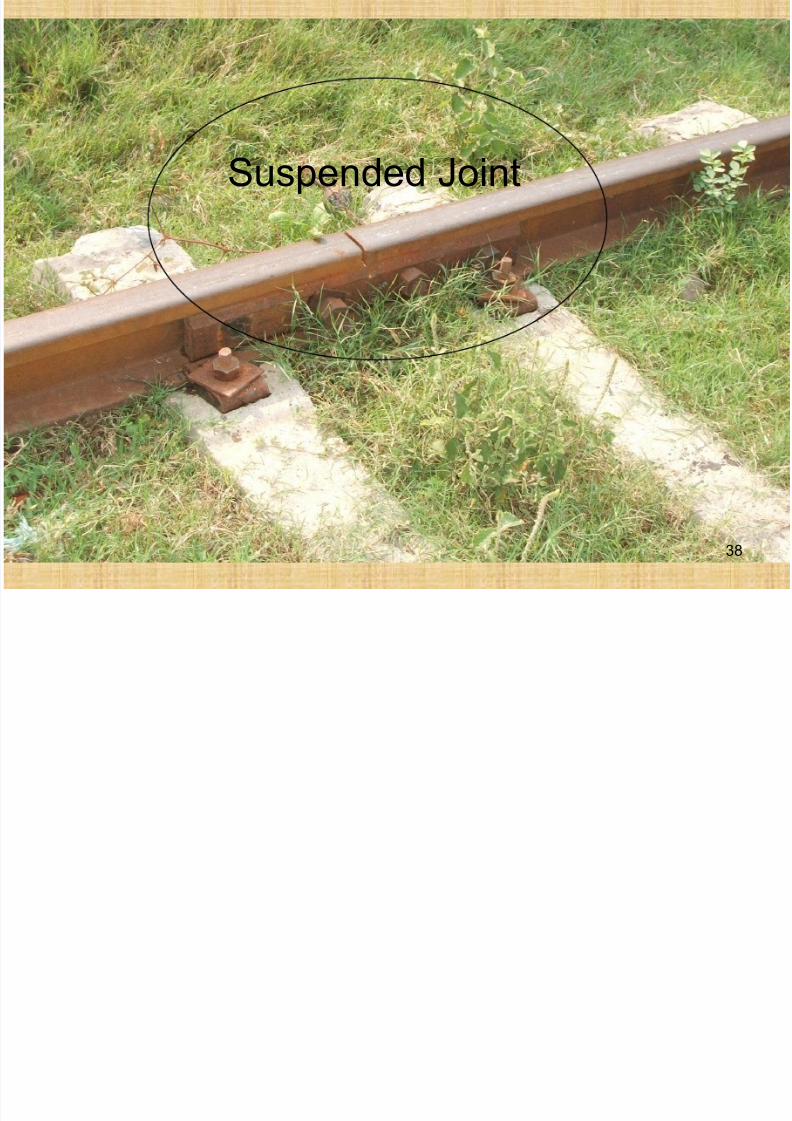
Suspended Joint
• In suspended joints, the ends of the rails
are suspended between the two sleepers.
• The load is distributed equally between the
two sleepers.
36
7/21/2019 Railways, Rails
http://slidepdf.com/reader/full/railways-rails 37/77
Supported and Suspended
Joints
37
Suspended Joint
7/21/2019 Railways, Rails
http://slidepdf.com/reader/full/railways-rails 38/77
Suspended Joint
38
7/21/2019 Railways, Rails
http://slidepdf.com/reader/full/railways-rails 39/77
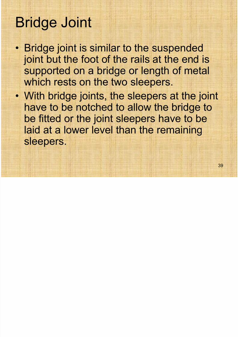
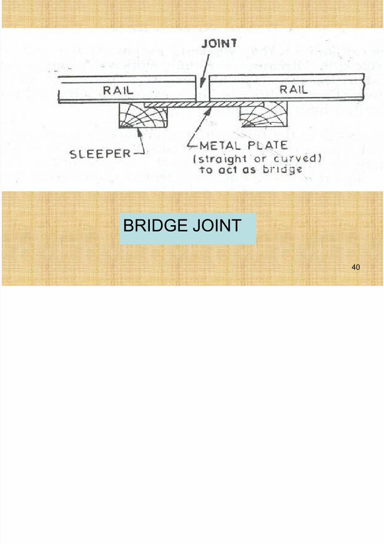
Bridge Joint
• Bridge joint is similar to the suspended joint but the foot of the rails at the end issupported on a bridge or length of metal
which rests on the two sleepers.• With bridge joints, the sleepers at the joint
have to be notched to allow the bridge tobe fitted or the joint sleepers have to belaid at a lower level than the remainingsleepers.
39
7/21/2019 Railways, Rails
http://slidepdf.com/reader/full/railways-rails 40/77
BRIDGE JOINT
40
7/21/2019 Railways, Rails
http://slidepdf.com/reader/full/railways-rails 41/77
Wear of the Rails
Wear of the rails may be divided into three
categories
• Wear on top or head of rail
• Wear at the ends of rail
• Wear on the sides of head
41
7/21/2019 Railways, Rails
http://slidepdf.com/reader/full/railways-rails 42/77
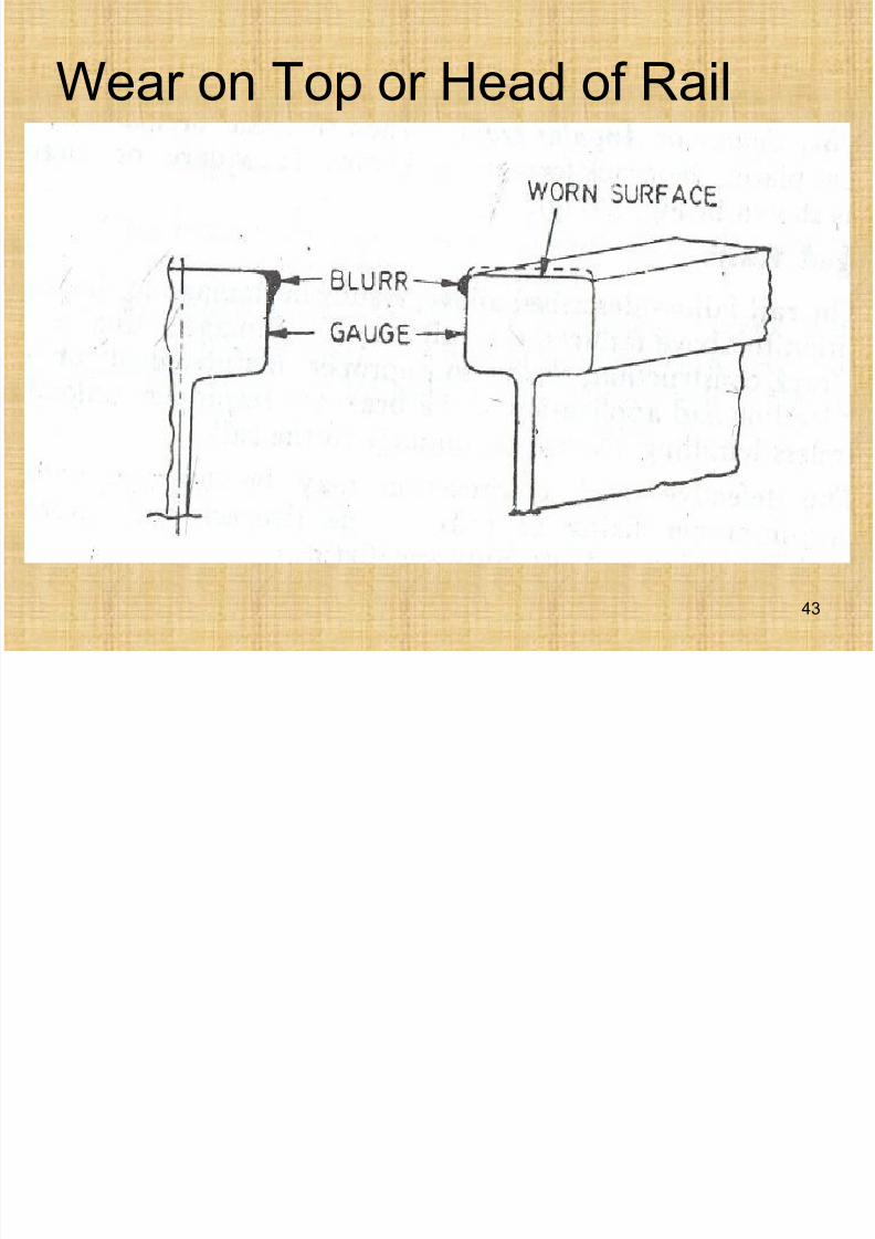
Wear on Top or Head of Rail
• The top surface of rails gets direct impactof the load from the wheels and henceabrasion, grounding and corrosion add to
the wearing of surface.• Sometimes the metal from the top moves
towards the sides and if it projects towardsthe gauge end, it disturbs the gauge.
• Head of the rail becomes worn due toabrasive action of the moving wheel.
42
7/21/2019 Railways, Rails
http://slidepdf.com/reader/full/railways-rails 43/77
Wear on Top or Head of Rail
43
7/21/2019 Railways, Rails
http://slidepdf.com/reader/full/railways-rails 44/77
Wear on Top or Head of Rail
• Impact of the moving load due to which head ofrail gets battered and chipped.
• Grinding action of sand or dust particlesbetween the wheels and the rails.
• If wheels are just slipping during starting, themetal in the rails head is burnt due to much heat.When brakes are applied to stop the train andsliding takes place, wear occurs.
• Wear is also increased by any loosenessbetween rails and sleepers and also due toloose packing of ballast.
44
7/21/2019 Railways, Rails
http://slidepdf.com/reader/full/railways-rails 45/77
Wear on Top or Head of Rail
• In case of gradient especially with curves,
the resistance is very much increased.
• Corrosion of rails on tracks adjoining to
sea and corrosion due to the action of the
acids contained in the refuse falling from
the trains, wear the top of the rail.
Remedy
• Use special alloy steel.
45
W th id f H d
7/21/2019 Railways, Rails
http://slidepdf.com/reader/full/railways-rails 46/77
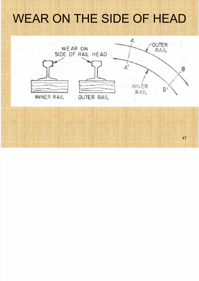
Wear on the sides of Head
This type of wear occurs along curved tracks.• On curves, due to centrifugal force the gauge
running face of the outer rail is rubbed by theflanges.
• Also the vehicles on the curve, do not bend tothe shape of curvature, so the head of the outerrail bends towards the gauge face therefore ishit by the flanges of the wheels
• On curve, the outer wheel has to cover moredistance but since wheels are rigidly fixed soinner wheel slides over the rail causing the wearof the rail.
46
7/21/2019 Railways, Rails
http://slidepdf.com/reader/full/railways-rails 47/77
WEAR ON THE SIDE OF HEAD
47
7/21/2019 Railways, Rails
http://slidepdf.com/reader/full/railways-rails 48/77
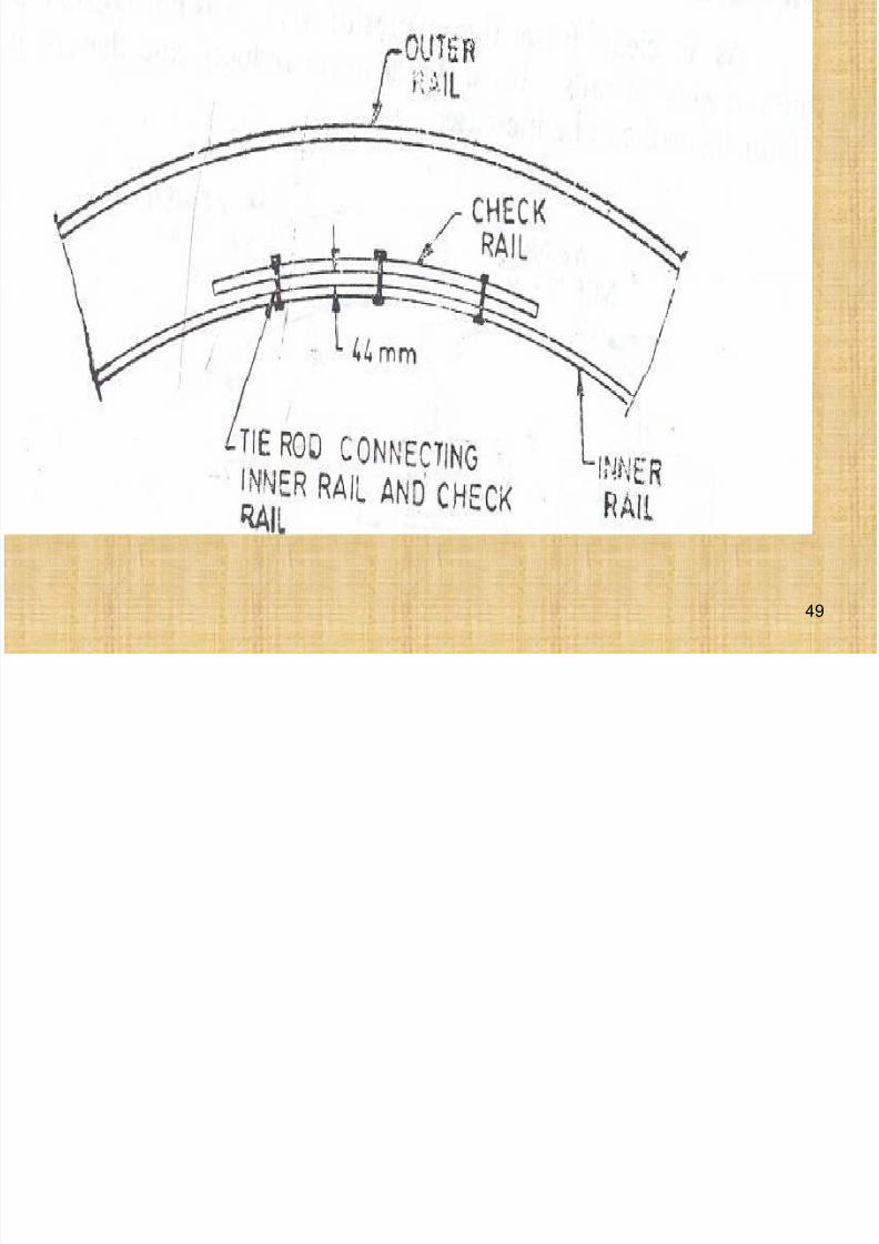
Remedies
• Use curves with larger radii if possible.
• Lubricate the side of the rail head.
• Exchange of inner and outer rails on the
curves.• If the curves are sharper than 8 degrees in
BG and 14 degrees or above in MG, use
check rails. The flange of the wheel isbetween the main rail and check rail socheck rail will be worn out.
48
7/21/2019 Railways, Rails
http://slidepdf.com/reader/full/railways-rails 49/77
49
W t th d f R il
7/21/2019 Railways, Rails
http://slidepdf.com/reader/full/railways-rails 50/77
Wear at the end of Rails
• This type of wear will be at the joints due tohammer blows which the end of the rail receiveswhen the wheel jumps the gap between the tworails. So the ends of the rails are battered.
• The surface of contact between rails andsleepers are worn and the effect of blow isincreased.
Remedial Measures
• Proper maintenance of joints.• Make the fittings tight.
• Minimize the joints.
50
7/21/2019 Railways, Rails
http://slidepdf.com/reader/full/railways-rails 51/77
Measuring wear of rails
Rail wear is determined by
• By measuring the actual weight and
comparing it to the standard weight.
• Profile of worn out rail is compared to the
standard profile. The reduction in the
cross-sectional area is compared to the
original x-sectional area to obtain % lossof weight.
51
7/21/2019 Railways, Rails
http://slidepdf.com/reader/full/railways-rails 52/77
Rail Corrugations
• Sometimes due to defects in laying out of the
track or due to poor maintenance of the track, or
due to steep gradient resulting in sudden
application of brakes, the head of the railsdevelops a wavy surface. Rails which develop
this defect are called corrugated rails.
• When train passes over such rails a roaring
noise is created and for this reason these railsare known as roaring rails.
52
7/21/2019 Railways, Rails
http://slidepdf.com/reader/full/railways-rails 53/77
Locations of Rail Corrugations
These defects generally develop in the following
locations:
- At starting and termination point of the track due
to braking action.- In long tunnels due to presence of humidity.
- On yielding formations or rails laid on soft
material like brick ballast.
• The only remedy for rail corrugations is to grind
the corrugation with special machines.
53
7/21/2019 Railways, Rails
http://slidepdf.com/reader/full/railways-rails 54/77
Hogging of Rails
• The battering action of the wheels over the
ends of the rails results in the rails getting
bent and deflected at the ends.
• The loose packing under the joint or theloose fish plates are primarily responsible
for the development of this defect.
54
7/21/2019 Railways, Rails
http://slidepdf.com/reader/full/railways-rails 55/77
Hogging of Rails
To rectify this defect any of the following
may be adopted.
- Cutting of the end of the rail by power saw.
- Replacing the hogged rail by the new one.
(Uneconomical but most effective)
- The worn out ends of the rails may be
improved by welding.
- By using dehogging machine.
55
B ckling of Rails
7/21/2019 Railways, Rails
http://slidepdf.com/reader/full/railways-rails 56/77
Buckling of Rails
• When the expansion joint is inadequate or the joint is very tight, free movement of the rails dueto temperature changes is prevented. Thisresults in the buckling of rails.
Remedial measures to prevent buckling:- Joint should not prevent expansion and
contraction of rails.
- The surface of contact between fish plates and
rails should be lubricated.- If rails are welded then either steel sleepersshould be provided or rails should be properlyanchored.
56
7/21/2019 Railways, Rails
http://slidepdf.com/reader/full/railways-rails 57/77
Rail Failures
• Horizontal cracks : This defect occurs at
the rail ends where worn out fish plates
are used for joining or the ballast is not
properly packed.Such crack develops due to shearing
stresses at the critical section i.e., the
junction between rail head and web.
57
7/21/2019 Railways, Rails
http://slidepdf.com/reader/full/railways-rails 58/77
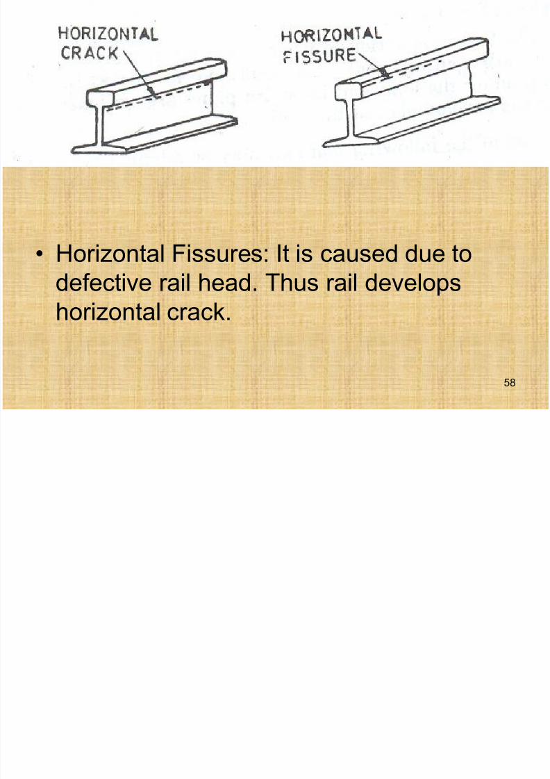
• Horizontal Fissures: It is caused due to
defective rail head. Thus rail developshorizontal crack.
58
7/21/2019 Railways, Rails
http://slidepdf.com/reader/full/railways-rails 59/77
Rail Failures
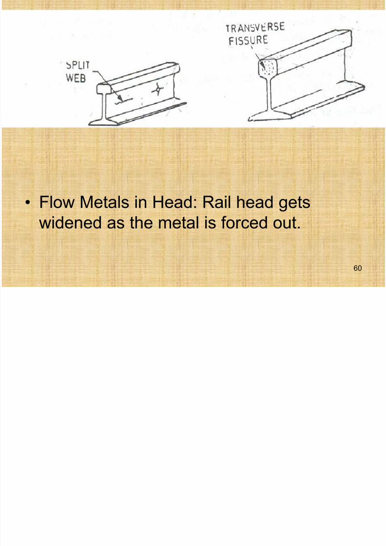
• Split Web: This is a horizontal crack
between the bolt holes in the web. It may
be propagated from the strained bolt hole.
The crack may be horizontal or verticalradiating from the bolt hole.
• Transverse Fissures: This is a
manufacturing defect. It starts from thecentre of head and spreads round the
head.59
7/21/2019 Railways, Rails
http://slidepdf.com/reader/full/railways-rails 60/77
• Flow Metals in Head: Rail head getswidened as the metal is forced out.
60
7/21/2019 Railways, Rails
http://slidepdf.com/reader/full/railways-rails 61/77
Rail Failures
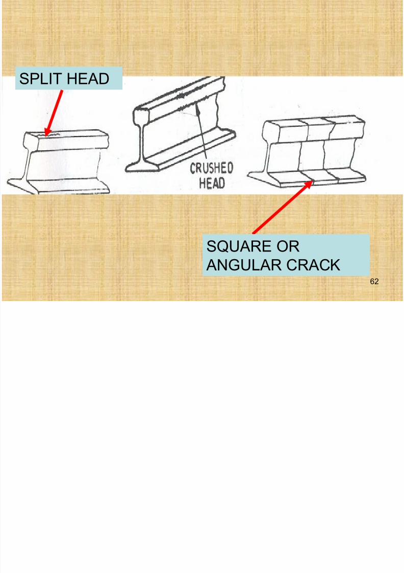
• Split Head: This is also a manufacturing
defect indicated by a crack on the top.
• Crushed Head: Head gets sagged or
flattened. This is due to skidding, slippingor due to weak end support.
• Square or angular crack: When rail breaks
through a vertical plane, the crack formedis known as square or angular.
61
7/21/2019 Railways, Rails
http://slidepdf.com/reader/full/railways-rails 62/77
SPLIT HEAD
SQUARE OR
ANGULAR CRACK62
7/21/2019 Railways, Rails
http://slidepdf.com/reader/full/railways-rails 63/77
Creep of Rails
Creep is the longitudinal movement of railsin the track.
Causes of Creep:
• Wave motion set up in the track by a moving
train.• Expansion and contraction of the rails due to
temperature.
• Starting, accelerating and slowing down or
stopping of a train. Rails of a track tend to creepbackward, when the train starts. Rails creep inthe forward direction when brakes are applied.
63
7/21/2019 Railways, Rails
http://slidepdf.com/reader/full/railways-rails 64/77
Creep due to Wave Motion
• Wave motion is set up in the track by amoving train. Portions of the railimmediately under the wheels of the trainare depressed slightly due to load on the
wheels.
• As the wheels move, the depressions
move with them, the previous depressedportions spring back to their original level.This wave motion tends to move the railforward with the train.
64
7/21/2019 Railways, Rails
http://slidepdf.com/reader/full/railways-rails 65/77
Creep due to Wave Motion
• The pitch and depth of the waves aregoverned by the condition of the formation,the stiffness of the track, the weight of therails, the spacing of the sleepers, the
quality and quantity of the ballast, thecondition of drainage and the standard ofmaintenance.
• Creep is reduced by increasing stiffness ofthe track, stability of soil in formation andangular ballast (which interlocks well).Thus wave motion is reduced. 65
Factors governing the Magnitude
7/21/2019 Railways, Rails
http://slidepdf.com/reader/full/railways-rails 66/77
g g gand Direction of Creep
- Alignment of Track : Creep is found to be greater onthe curves than on straight sections.
- Grade of Track : Creep is found to be more on the downgrade.
- Direction of the Heaviest Traffic: For places connectedto seaport, wagons are carrying more load. Creep isfound to be more in the direction heavier wagons aremoving.
- Condition of Formation: Creep is more in the newly
constructed formation. - Weight of the Rail Section: Creep is found more in the
lighter section.
66
Factors governing the Magnitude
7/21/2019 Railways, Rails
http://slidepdf.com/reader/full/railways-rails 67/77
g g gand Direction of Creep
• Creep is not constant at a point and it
does not vary at a uniform rate.
• Two rails of the track do not creep by the
same magnitude.
• Direction and magnitude of creep cannot
be predicted because both rails may creep
in one direction or in opposite directions.
67
7/21/2019 Railways, Rails
http://slidepdf.com/reader/full/railways-rails 68/77
Results of Creep
• Widening of gaps: At some places therail joints open beyond their limits and theintensity of hammer blows increases
resulting in greater stresses in the fishplates and bolts. At some places, joints get jammed preventing the expansion, whichresults in the buckling of the rail.
• The sleepers are moved out of square andout of position and consequently thegauge and alignment of the track is
disturbed.68
7/21/2019 Railways, Rails
http://slidepdf.com/reader/full/railways-rails 69/77
Results of Creep
• Points and crossings get distorted and it isvery difficult to keep them back to correctgauge or to correct alignment.
69
7/21/2019 Railways, Rails
http://slidepdf.com/reader/full/railways-rails 70/77
Methods to correct Creep
• Pull Back Method
• Creep Anchors
70
7/21/2019 Railways, Rails
http://slidepdf.com/reader/full/railways-rails 71/77
Pull Back Method
• The track to be pulled back is inspected and theextent of pulling back necessary at variousplaces is noted. The point from which to start isalso determined; usually the starting point is at
widely opened rail joints.• Pulling back should be regulated in such a way
that rail joints are made central over thesleepers. It is not enough to obtain only the
necessary expansion gaps but also position ofone rail joint relative to the joint on opposite sideof the rail must also be maintained.
71
7/21/2019 Railways, Rails
http://slidepdf.com/reader/full/railways-rails 72/77
Pull Back Method
• Fish plates or fish bolts at one end of therail are removed and at the other end areloosened. Fittings, which hold the rail with
sleepers are also made loose. The rail isthen pushed backed by using a lever rod.
• Mechanical devices can also be used forthis purpose.
72
7/21/2019 Railways, Rails
http://slidepdf.com/reader/full/railways-rails 73/77
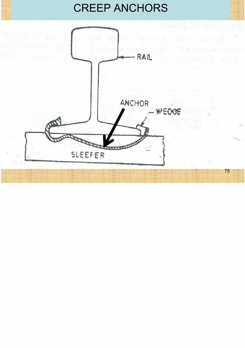
Creep Anchors or Anti Creepers
• After pulling back, there is no guarantee that therails will not creep again. Infact, they startcreeping immediately after pulling back.
• Creep is prevented or reduced by devices
known as creep anchors or anti-creepers. Suchanchors are fastened to the foot of the rail bymeans of spring grip and bear against the sideof the sleepers. When the rails tend to creep,
they have to drag the sleepers also through theballast and the ballast offers sufficient resistanceto prevent the creep of rails.
73
7/21/2019 Railways, Rails
http://slidepdf.com/reader/full/railways-rails 74/77
Number of Creep Anchors
• Minimum No. of Creep Anchors = 2 in one
rail panel
• Maximum No. of Creep Anchors = 2 x No.
of sleepers in one rail panel
• Creep anchors should resist the stresses
due to the creep of the rails.
74
CREEP ANCHORS
7/21/2019 Railways, Rails
http://slidepdf.com/reader/full/railways-rails 75/77
75
7/21/2019 Railways, Rails
http://slidepdf.com/reader/full/railways-rails 76/77
Bearing Plates
• Bearing Plates are simply the metallicplates and are placed between the foot ofthe rail and sleeper, in order to minimize
the injury to the wooden sleepers.Functions of Bearing Plates
• Protect the wooden sleeper
• Distribute the load over wider area of thewooden sleepers
• Reduce the maintenance
76
7/21/2019 Railways, Rails
http://slidepdf.com/reader/full/railways-rails 77/77
Bearing Plates
• The shape of the bearing plate is rectangularand made of mild steel, cast iron or wrought
iron.
• The size of the bearing plate is 9”x10”x3/8”.
• It has 4 holes for spikes.