Embed Size (px)
Citation preview
RAILWAY INVESTIGATION REPORT R07T0323
MAIN TRACK DERAILMENT
CANADIAN NATIONAL TRAIN NUMBER M-38461-29
MILE 9.30, HALTON SUBDIVISION MALPORT, ONTARIO
30 OCTOBER 2007
The Transportation Safety Board of Canada (TSB) investigated this occurrence for the purpose of advancing transportation safety. It is not the function of the Board to assign fault or determine civil or criminal liability.
Railway Investigation Report Main Track Derailment Canadian National Train Number M-38461-29 Mile 9.30, Halton Subdivision Malport, Ontario 30 October 2007 Report Number R07T0323
Summary On 30 October 2007 at approximately 0856 eastern daylight time, eastward Canadian National (CN) railway train number M-38461-29 stopped at Mile 8.00 of the Halton Subdivision to set off a block of intermodal cars at Malport, Ontario. The cars were marshalled at the head-end of the train. After completing the set-out, the locomotives were re-coupled to the remainder of the train, a brake test was performed, and the train attempted to depart. After four unsuccessful attempts, the conductor detrained and determined that 32 cars had derailed and approximately 2500 feet of track was damaged or destroyed. There were no injuries and no dangerous goods were released.
Ce rapport est également disponible en français.
- 2 -
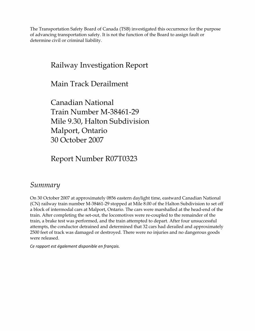
Other Factual Information On 30 October 2007, at 0344 eastern daylight time (EDT), 1eastward Canadian National (CN) freight train M-38461-29 (train 384) departed Sarnia, Ontario, destined for Toronto. The train consisted of 4 locomotives and 131 car bodies (59 loads and 72 empties). It weighed 7810 tons and was 7839 feet in length. The train contained a block of 16 intermodal cars (34 car bodies) that were marshalled directly behind the locomotives and destined for set-out at the Brampton Intermodal Terminal 2 (BIT) in Malport, Ontario (see Figure 1).
BIT is one of the largest intermodal terminals in Canada. The terminal handles approximately 60 million gross tons (mgt) of traffic annually, with 16 train movements per day. On occasion, blocks of intermodal cars scheduled for set-out at BIT are handled in mixed freight consists such as on train 384. For these set-outs, the train stops on the main-line, the block of intermodal cars is cut out and delivered to the terminal, and then the locomotives re-couple to the remaining cars and continue their journey. Eastbound traffic enters and departs BIT using a connecting wye that joins the north track of the Halton Subdivision at Mile 8.81 and Mile 8.70.
1 All times are EDT (Coordinated Universal Time minus four hours). 2 An intermodal terminal is a railroad facility designed for loading and unloading containers
and trailers to and from flat cars for movement on the railroad and subsequent or prior movement on streets or highways.
Figure 1. Derailment location map (Source: Railway Association of Canada,
Canadian Railway Atlas)
- 3 -
At Mile 8.80, there is a triple-track grade crossing at Goreway Drive. This north-south arterial road, with frequently-scheduled public transportation vehicles travelling and a speed limit of 60 km/h, crosses both tracks of the Halton Subdivision and BIT wye Track 1. The Goreway Drive crossing is protected by flashing lights, bells, and gates, with signal activation circuits located approximately 2500 feet west of the crossing. The Halton Subdivision extends eastward from Mile 49.5, the junction with the Oakville Subdivision in Burlington, Ontario, to Mile 0.0, where it joins the York Subdivision in Toronto. In the vicinity of the derailment, the Halton Subdivision consists of double main track with a maximum permissible speed of 50 mph for freight and passenger trains. At the time of the derailment, there were no speed restrictions in the vicinity of the derailment. Thirty-six freight trains and four passenger trains traverse the Halton Subdivision each day, accounting for 87 mgt of traffic annually. Train movements on this subdivision are controlled by centralized traffic control (CTC), authorized by the Canadian Rail Operating Rules (CROR) and supervised by a rail traffic controller located in Toronto. The train crew consisted of a locomotive engineer and a conductor. Both crew members met fitness and rest standards, were qualified for their respective positions, and were familiar with the subdivision and the procedures for setting out intermodal cars at BIT. On the day of the occurrence, the train was travelling east on the north main track of the Halton Subdivision. The train was slowed using dynamic braking to allow the conductor to detrain in the vicinity of Mile 9.0. The train then pulled forward approximately 3000 feet and was brought to a stop using the train air brakes. The locomotive’s independent brake was not bailed off. 3 The conductor made the cut, entrained, and the cars were shoved in to BIT (see Figure 2).
3 The air brakes on a diesel or electric locomotive are “independent” of the brakes used on the
rest of the train. When a train (“automatic”) brake application is made, the locomotive will react the same as any other rolling stock (apply its brakes). However, braking force at the locomotive will develop faster than at other locations throughout the train. This can result in elevated buff (compression) forces during braking, leading to skidding of the locomotive wheels. To prevent this situation, the engineer can override or “bail-off” the brake application on the locomotive(s).
- 4 -
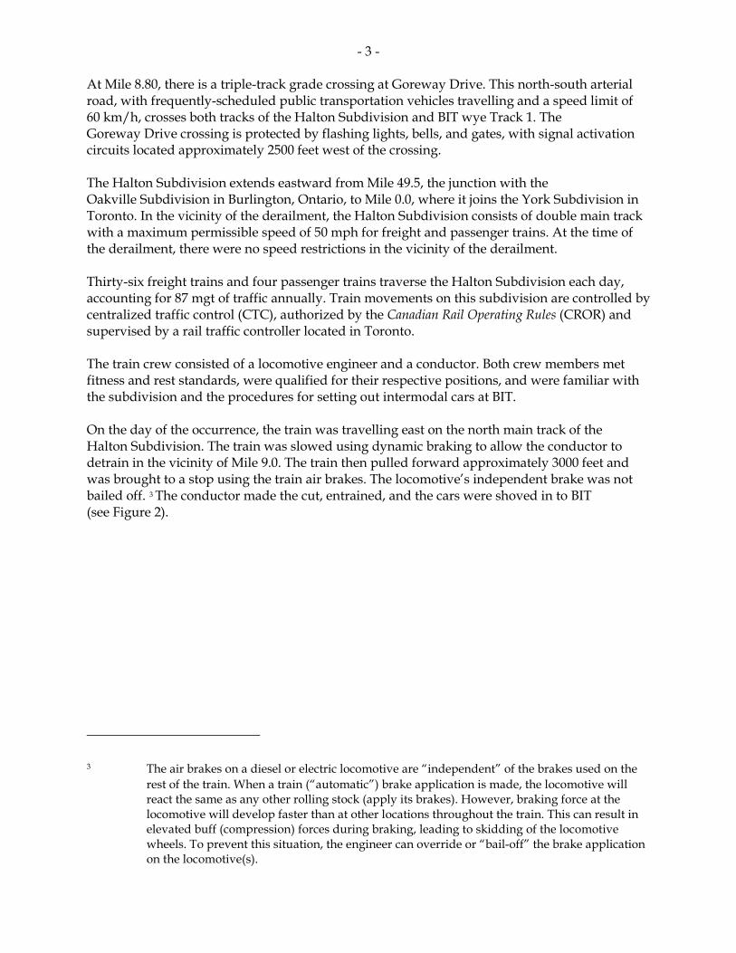
After completing the set-out, the train crew returned to the portion of the train that had been left on the main-line and coupled the locomotives to the remaining cars, consisting of 25 loaded cars and 72 empty cars. The train then weighed approximately 5336 tons and was 5323 feet long. After charging the air brake system, the crew attempted to depart. Train 384 accelerated to a speed of 11 mph in throttle 6, but forward movement could not be sustained. The train movement stopped after travelling 0.35 miles (1848 feet). Three subsequent attempts to pull were made. Although there was continuity in the air brake system, the train would not move. The conductor then looked back towards the tail-end of the train and observed derailed cars. Approximately one hour and ten minutes had elapsed between the time the train first came to a stop and when the derailment was discovered. There were no injuries and no release of product. The head-end portion of the train that was not derailed was pulled clear of the crossing at Goreway Drive. At the time of the derailment, the weather was clear and sunny with a temperature of 12°C and a slight wind. Site Examination Site examination revealed that the 20th to the 51st cars had derailed, including seven dangerous commodity residue cars. All cars remained upright with minimal damage. Approximately 2500 feet of main-line track was damaged or destroyed.
Figure 2. Derailment site at entrance to BIT
Gauge side wheel marks on rail head and web of rail
- 5 -
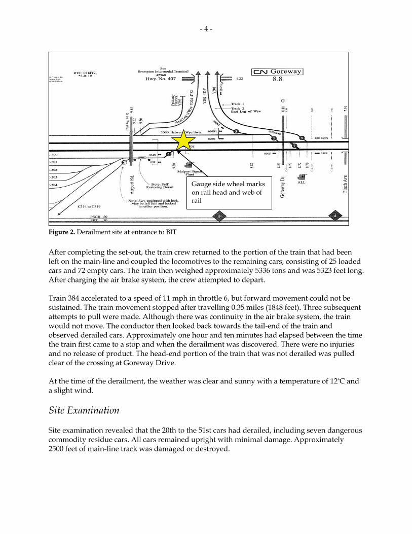
The derailed cars were stretched east to west along the north main-line between the crossing at Goreway Drive and the signal structure at Mile 9.3. The derailed cars did not obstruct the south main track. Examination of the rail revealed multiple wheel flange marks on the gauge side of the north and south rail. Some wheelsets were straddling the south rail, east of where the rail had fractured at thermite welds. Damage to crossties, anchors, and spikes was predominantly to the gauge side of both rails. The wheel marks were traced back to the vicinity of Mile 9.3, where there were marks on the head and gauge side of the south rail (see Photo 1). Approximately 20 feet to the east, there were similar wheel marks on the north rail. In the vicinity of these wheel marks, spikes on the gauge side were lifted, consistent with the rail having canted out.
Wheel marks on gauge side of south rail at Mile 9.3
Photo 1. Mile 9.3 of the north track of the Halton
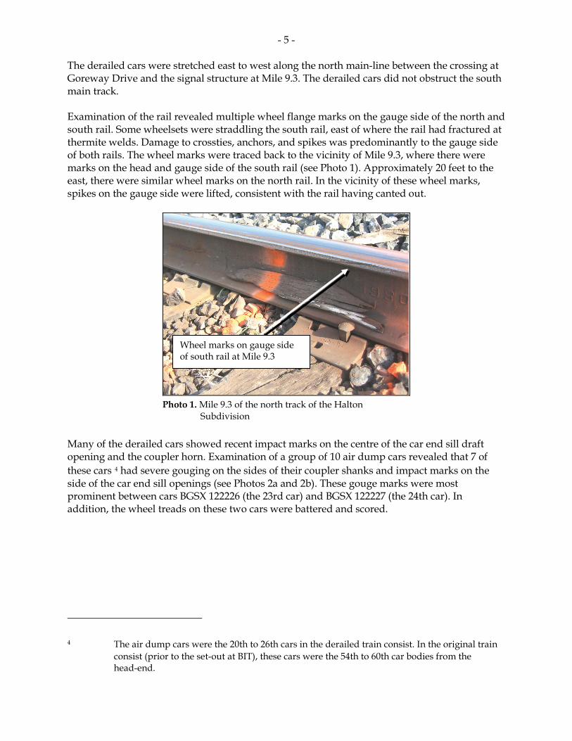
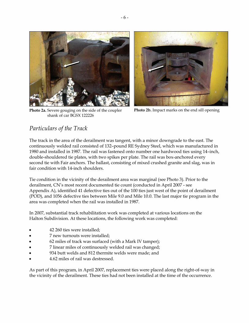
Subdivision Many of the derailed cars showed recent impact marks on the centre of the car end sill draft opening and the coupler horn. Examination of a group of 10 air dump cars revealed that 7 of these cars 4 had severe gouging on the sides of their coupler shanks and impact marks on the side of the car end sill openings (see Photos 2a and 2b). These gouge marks were most prominent between cars BGSX 122226 (the 23rd car) and BGSX 122227 (the 24th car). In addition, the wheel treads on these two cars were battered and scored.
4 The air dump cars were the 20th to 26th cars in the derailed train consist. In the original train
consist (prior to the set-out at BIT), these cars were the 54th to 60th car bodies from the head-end.
- 6 -
Photo 2a. Severe gouging on the side of the coupler
shank of car BGSX 122226
Photo 2b. Impact marks on the end sill opening
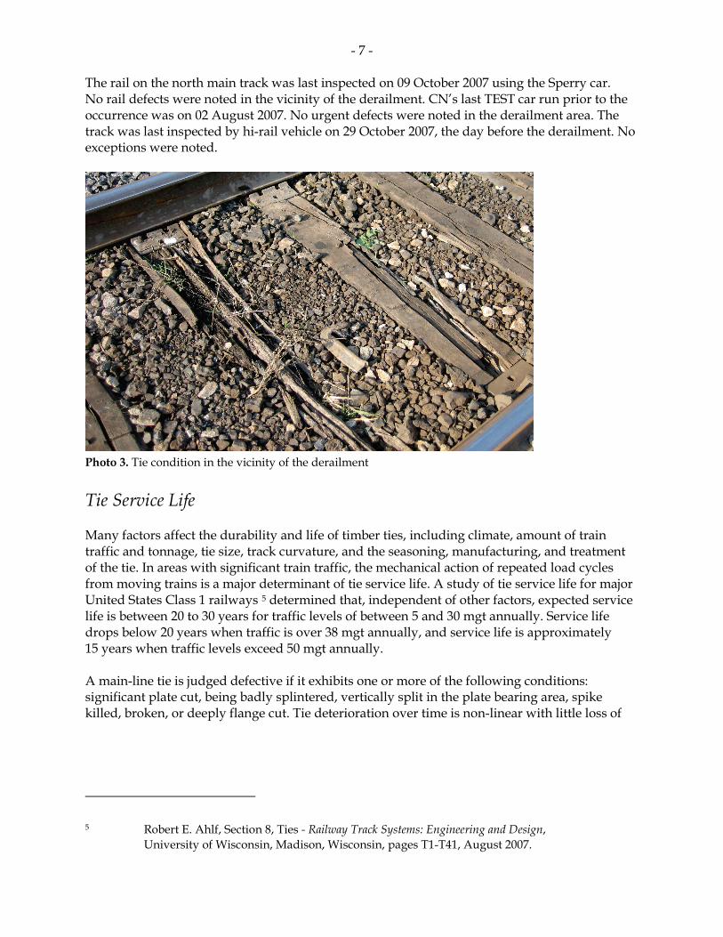
Particulars of the Track The track in the area of the derailment was tangent, with a minor downgrade to the east. The continuously welded rail consisted of 132–pound RE Sydney Steel, which was manufactured in 1980 and installed in 1987. The rail was fastened onto number one hardwood ties using 14–inch, double-shouldered tie plates, with two spikes per plate. The rail was box-anchored every second tie with Fair anchors. The ballast, consisting of mixed crushed granite and slag, was in fair condition with 14-inch shoulders. Tie condition in the vicinity of the derailment area was marginal (see Photo 3). Prior to the derailment, CN’s most recent documented tie count (conducted in April 2007 - see Appendix A), identified 41 defective ties out of the 100 ties just west of the point of derailment (POD), and 1056 defective ties between Mile 9.0 and Mile 10.0. The last major tie program in the area was completed when the rail was installed in 1987. In 2007, substantial track rehabilitation work was completed at various locations on the Halton Subdivision. At these locations, the following work was completed: • 42 260 ties were installed; • 7 new turnouts were installed; • 62 miles of track was surfaced (with a Mark IV tamper); • 7 linear miles of continuously welded rail was changed; • 934 butt welds and 812 thermite welds were made; and • 4.62 miles of rail was destressed. As part of this program, in April 2007, replacement ties were placed along the right-of-way in the vicinity of the derailment. These ties had not been installed at the time of the occurrence.
- 7 -
The rail on the north main track was last inspected on 09 October 2007 using the Sperry car. No rail defects were noted in the vicinity of the derailment. CN’s last TEST car run prior to the occurrence was on 02 August 2007. No urgent defects were noted in the derailment area. The track was last inspected by hi-rail vehicle on 29 October 2007, the day before the derailment. No exceptions were noted.
Tie Service Life Many factors affect the durability and life of timber ties, including climate, amount of train traffic and tonnage, tie size, track curvature, and the seasoning, manufacturing, and treatment of the tie. In areas with significant train traffic, the mechanical action of repeated load cycles from moving trains is a major determinant of tie service life. A study of tie service life for major United States Class 1 railways 5 determined that, independent of other factors, expected service life is between 20 to 30 years for traffic levels of between 5 and 30 mgt annually. Service life drops below 20 years when traffic is over 38 mgt annually, and service life is approximately 15 years when traffic levels exceed 50 mgt annually. A main-line tie is judged defective if it exhibits one or more of the following conditions: significant plate cut, being badly splintered, vertically split in the plate bearing area, spike killed, broken, or deeply flange cut. Tie deterioration over time is non-linear with little loss of
5 Robert E. Ahlf, Section 8, Ties - Railway Track Systems: Engineering and Design,
University of Wisconsin, Madison, Wisconsin, pages T1-T41, August 2007.
Photo 3. Tie condition in the vicinity of the derailment
- 8 -
usefulness in the first 2/3 to 3/4 of its life. However, once wood fibres begin to break down, further deterioration can be rapid. On heavy tonnage main-lines, once ties display signs of visible or functional deterioration, failure can occur within one to two years. 6 Track Safety Rules and Inspections The Rules Respecting Track Safety (TSR) 7 prescribe minimum safety requirements for railway track that is part of the general railway system of transportation. Part II A establishes the maximum allowable operating speeds (in mph) for various classes of track (see Table 1). The railway operates the Halton Subdivision as Class 4 track. Over track that meets all of the requirements prescribed in this part for:
The maximum allowable operating speed for freight trains is:
The maximum allowable operating speed for passenger trains is:
Class 1 track 10 15
Class 2 track 25 30
Class 3 track 40 60
Class 4 track 60 80
Class 5 track 80 95 (for Light, Rapid, Comfortable (LRC) trains, 100)
Class 6 track 110 110
Table 1. Maximum Allowable Operating Speeds Part II D-II establishes the minimum standards for tie condition for each class of track. It states (in part):
(c) Each 39-foot segment of: Class 1 track shall have 5 crossties; Class 2 track shall have 8 crossties; Class 3 track shall have 10 crossties; Class 4 and 5 tracks shall have 12 crossties; and Class 6 track shall have 14 crossties,
6 See footnote number 5. 7 Rules Respecting Track Safety, also known as the Track Safety Rules, revised July 2000, TC E-26,
since revised 17 March 2008 (TC E-30).
- 9 -
which are not:
(1) Broken through;
(2) Split or otherwise impaired to the extent the crossties will allow ballast to work through, or will not hold spikes or rail fasteners;
(3) So deteriorated that the tie plate or base of rail can move laterally more than ½ inch relative to the crossties; or
(4) Cut by the tie plate through more than 40 per cent of a tie’s thickness.
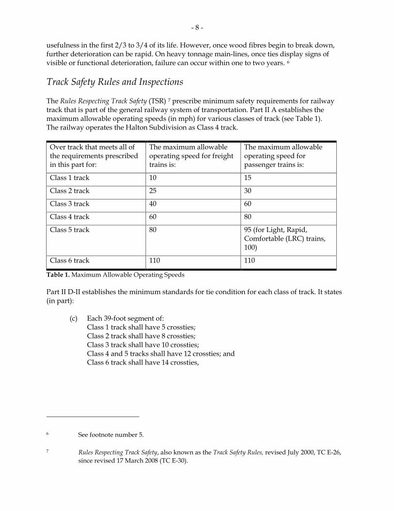
Transport Canada’s (TC) last inspection of the south track of the Halton Subdivision occurred on 15 June 2006. Eight defects were documented, including five for defective crossties on the south track. CN remediation work on the south track, including the installation of safety ties, plugging, and extra spiking was completed between June 16th and June 29th 2006. There are no TC inspection records indicating that the north track, in the vicinity of the derailment, had been inspected within the 2-year period prior to the occurrence. Air Dump Cars Air dump cars (see Photo 4) are used for carrying bulk materials such as iron ore and ballast. The typical air dump car is comprised of a steel frame on trucks and a pivotally-connected hopper body. The hopper body consists of side doors that open when the body is tilted at an angle sufficient to discharge the bulk material. Once activated, pneumatic rams attached to the frame of the car will initiate the dumping function. A piston raises the bed on one side, discharging the material over the other side of the car through the opened side door.
The air dump cars (BGSX series) involved in this derailment were designed and manufactured for use in the mining industry. These cars had been custom designed to operate on severe curvature track and on track built on loose fill (for example, temporary track). To minimize the possibility of a derailment, the cars were equipped with Association of American Railroads
Photo 4. BGSX series air dump cars
- 10 -
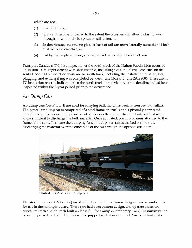
(AAR) Type E bottom-operated couplers. These couplers consisted of a locomotive-type, heavy-duty swivel butt and solid vertical swivel pin. The couplers were designed to swing to a maximum of 13 degrees to each side of the centreline. Some of the air dump cars involved in this occurrence were designed to carry a cab unit for controlling car dumping activities. However, the cab unit on these cars had either been removed or had not been installed. These cars, such as BGSX 122226 had an extended end sill (see Photo 5).
The Quebec Cartier Mining Company had purchased these air dump cars for use in its closed loop mining operation. The cars were purchased from Strata Mining in Grand Forks, North Dakota, and were en route to Baie-Comeau, Quebec. On arrival, the cars were to be loaded onto road trailers and transported to their final destination at Port-Cartier, Quebec. CN Train Handling Policy CN trains are marshalled to be compliant with CN’s train handling guidelines, policies, practices, and procedures. Cars are marshalled into blocks, by destination. Train crews tasked with lifting or setting-out specific blocks of cars at various locations en route are encouraged to conduct these activities as efficiently and as safely as possible. CN’s train handling procedures are set out in its Locomotive Engineer Operating Manual – Form 8960, section G1, Train Handling Policy. The policy specifies (in part):
• Locomotive engineers should have a thorough knowledge of the physical characteristics of the territory they will be operating and use this knowledge and good judgement to ensure proper train handling techniques;
• Locomotive engineers must utilize “forward planning” in consideration of territory profiles, planned stops, required speed adjustments and slack control, avoiding aggressive use of the locomotive throttle and train braking systems;
Photo 5. Side view of BGSX 122226 (extended end sill) and BGSX 122227
Extended End
- 11 -
• Throttle manipulation must be used as the primary means of controlling the train; and
• Dynamic brake must be fully utilized as the initial braking force.
AAR Guidelines for Potentially Troublesome Equipment It is widely recognized in the rail industry that there are specific cars and special loads that require special handling. The AAR has described these cars as “potentially troublesome”. In 1979, the AAR published a train handling guideline for the industry based on research conducted into the behaviour of cars. According to AAR Research Reference R-185, section 3.9, Special Type and Potentially Troublesome Equipment, specifies (in part):
Many specific cars and special loads require special handling due to the design of the equipment, the lading on the cars or the configuration of a series of these cars. Equipment which is recognized as potentially troublesome should be analysed dynamically, considering the loading of the car, the location of the car within the train and the physical features of the track to be traversed.
AAR Requirements for the Testing and Certification of Railcars AAR M1001 8 Chapter II, paragraph 2.1.6, specifies that rail cars should produce a truck side lateral force to vertical force (L/V) ratio of less than 0.82 under a pull force of 200 000 lbf (pound force) when on a 10-degree curve. In the AAR guideline, there is no requirement to check the L/V ratio for buff conditions (such as the jackknife scenario). In this occurrence, the swivel-butt coupler on the BGSX cars, which permit drawbar angles up to 13 degrees, is compliant with AAR requirement M1001, paragraph 2.1.6. TSB Laboratory Analysis TSB Engineering Laboratory examination included: • the identification of the suspected first derailed cars; • the calculation of in-train force and transformed lateral force during the derailment
event; • the evaluation of the effects of car design on the derailment; • the evaluation of the effects of brake application on the derailment; and • the evaluation of the effects of track condition on the derailment.
8 AAR Manual of Standards and Recommended Practices, section II, M1001.
- 12 -
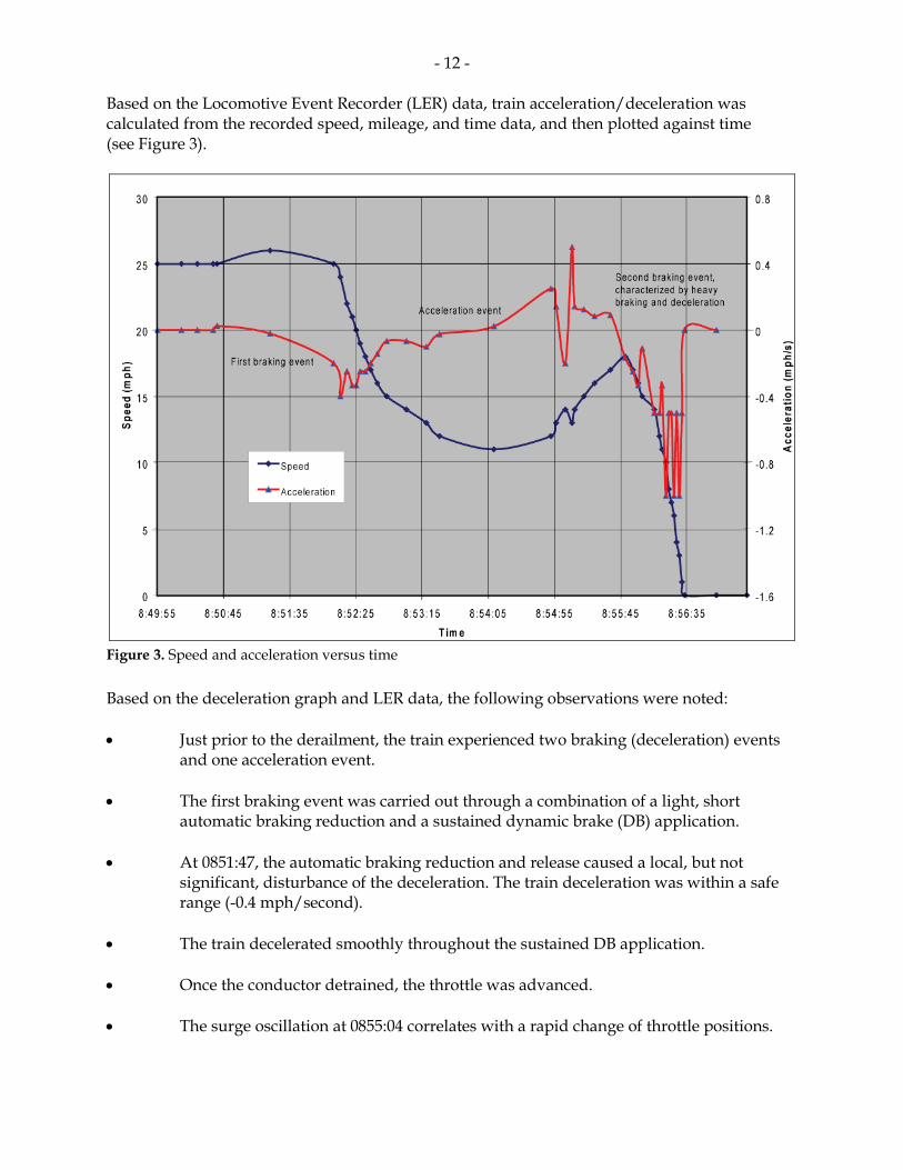
Based on the Locomotive Event Recorder (LER) data, train acceleration/deceleration was calculated from the recorded speed, mileage, and time data, and then plotted against time (see Figure 3).
Figure 3. Speed and acceleration versus time Based on the deceleration graph and LER data, the following observations were noted: • Just prior to the derailment, the train experienced two braking (deceleration) events
and one acceleration event. • The first braking event was carried out through a combination of a light, short
automatic braking reduction and a sustained dynamic brake (DB) application. • At 0851:47, the automatic braking reduction and release caused a local, but not
significant, disturbance of the deceleration. The train deceleration was within a safe range (-0.4 mph/second).
• The train decelerated smoothly throughout the sustained DB application. • Once the conductor detrained, the throttle was advanced. • The surge oscillation at 0855:04 correlates with a rapid change of throttle positions.
- 13 -
• The second braking event was characterized by heavy braking and deceleration. The locomotive independent brake was not bailed off, allowing a rapid build-up of the locomotive independent brake. As brake cylinder pressure approached a full nominal application of 80 pounds per square inch just before the final stop, three deceleration peaks of approximately 1 mph/s occurred.
By correlating train location with the deceleration events, it was determined that two air dump cars (BGSX 122226 and BGSX 122227) were in the vicinity of the POD (approximately Mile 9.3) during the deceleration peaks. The laboratory analysis also determined: • For the suspected first derailed cars (BGSX 122226 and BGSX 122227), the maximum
in-train buff force following the heavy independent brake application was estimated to be approximately 175 kips (1 kip = 1000 pounds).
• The couplers of BGSX 122227 were longitudinally aligned off the car centreline. • Cars BGSX 122227 and BGSX 122226 were equipped with couplers which can swing
to a maximum drawbar angle of 13 degrees. • At the maximum 13 degree drawbar angle, the transformed truck side L/V ratios for
cars BGSX 122226 and BGSX 122227 were between 1.9 and 2.1. • The 100 track ties just west of the POD were in marginal condition with a 41 per cent
failure rate. For such track, the estimated rail roll over resistance (L/V ratio) is approximately 1.3. In comparison, for new track with the same spike pattern, the rail roll over resistance is approximately 2.77. For 10-year old track, the rail roll over resistance is approximately 2.34.
Other Related Occurrences Since 2002, there have been a number of derailments involving cars with draft/coupler systems that permit large drawbar angles. These occurrences include: • On 02 March 2005, CN freight train M31031-02 (train 310) derailed 16 cars while being
brought to a controlled stop on tangent track at Coteau, Quebec. The derailed cars included 10 BGSX air dump cars, which were part of an order of 27 air dump cars en route to Quebec Cartier Mining Company in Baie-Comeau, Quebec. The air dump cars were equipped with couplers that permitted a maximum drawbar angle of 13 degrees. The empty air dump cars, the 4th to the 31st cars behind the locomotives, had been placed on the head-end of the train, with 67 loaded grain cars at the tail-end.
• On 28 April 2007, CN freight train M36321-26, travelling at 46 mph, experienced a
train-initiated emergency brake application, resulting in the derailment of 23 cars in the town of Cobourg, Ontario. The first derailed car was a track maintenance machine that was equipped with a non-standard coupler permitting drawbar angles in the range of 30 degrees (TSB report R07T0110).
- 14 -
• On 08 July 2002, CN freight train A44251-08 derailed 2 locomotives and the first
27 car bodies. Under braking, the non-alignment couplers on the derailed locomotives permitted maximum drawbar angles of approximately 19 degrees. Buff forces translated through these couplers generated lateral forces which were sufficient to cause rail roll and wheel lift, leading to the derailment (TSB report R02C0050).
• On 27 May 2005, Canadian Pacific Railway freight train 277-26 derailed 2 locomotives
and the first 24 cars, including 3 residue tank cars (last containing anhydrous ammonia). A combination of high buff forces during an abrupt dynamic brake application and a large drawbar angle (up to 19 degrees) due to couplers without alignment control produced excessive transformed lateral forces that rolled the rail, leading to the derailment (TSB report R05C0082).
Analysis Introduction Train 384 was not particularly long or heavy. The crew members were experienced and were familiar with the territory and the procedures for setting out cars at this location. There were no pre-existing urgent rail or track geometry defects. There was no train-initiated or crew-initiated emergency braking. However, 32 cars derailed and approximately 2500 feet of track was damaged or destroyed. The derailment of train 384 was not a single derailment, but rather two derailments occurring approximately one hour apart. The analysis will examine the sequence of events encompassing the derailments. It will consider the contribution of equipment, track, and train-handling factors to the derailment. In doing so, the analysis will consider: • special handling instructions for potentially troublesome cars; • requirements for testing couplers/draft systems; and • prioritization of planned track maintenance. The Accident The First Derailment Event Impact marks on the coupler shank and end sill opening in a group of derailed air dump cars were consistent with a train slack run-in event. Track damage was consistent with rail roll out and wheel drop in. A dynamic analysis was conducted, focusing on the two air dump cars with the most damage: BGSX 122226 and BGSX 122227 (the 39th and 40th cars in the train consist, prior to the setoff of cars at BIT). Based on analysis of detailed track, equipment, and event recorder data, it appears that an elevated buff force event occurred when the train originally came to a stop on the Halton Subdivision. The timing of the buff force event placed the two air
- 15 -
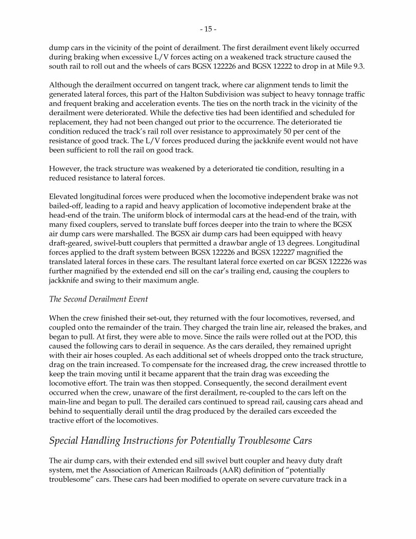
dump cars in the vicinity of the point of derailment. The first derailment event likely occurred during braking when excessive L/V forces acting on a weakened track structure caused the south rail to roll out and the wheels of cars BGSX 122226 and BGSX 12222 to drop in at Mile 9.3. Although the derailment occurred on tangent track, where car alignment tends to limit the generated lateral forces, this part of the Halton Subdivision was subject to heavy tonnage traffic and frequent braking and acceleration events. The ties on the north track in the vicinity of the derailment were deteriorated. While the defective ties had been identified and scheduled for replacement, they had not been changed out prior to the occurrence. The deteriorated tie condition reduced the track’s rail roll over resistance to approximately 50 per cent of the resistance of good track. The L/V forces produced during the jackknife event would not have been sufficient to roll the rail on good track. However, the track structure was weakened by a deteriorated tie condition, resulting in a reduced resistance to lateral forces. Elevated longitudinal forces were produced when the locomotive independent brake was not bailed-off, leading to a rapid and heavy application of locomotive independent brake at the head-end of the train. The uniform block of intermodal cars at the head-end of the train, with many fixed couplers, served to translate buff forces deeper into the train to where the BGSX air dump cars were marshalled. The BGSX air dump cars had been equipped with heavy draft-geared, swivel-butt couplers that permitted a drawbar angle of 13 degrees. Longitudinal forces applied to the draft system between BGSX 122226 and BGSX 122227 magnified the translated lateral forces in these cars. The resultant lateral force exerted on car BGSX 122226 was further magnified by the extended end sill on the car’s trailing end, causing the couplers to jackknife and swing to their maximum angle. The Second Derailment Event When the crew finished their set-out, they returned with the four locomotives, reversed, and coupled onto the remainder of the train. They charged the train line air, released the brakes, and began to pull. At first, they were able to move. Since the rails were rolled out at the POD, this caused the following cars to derail in sequence. As the cars derailed, they remained upright with their air hoses coupled. As each additional set of wheels dropped onto the track structure, drag on the train increased. To compensate for the increased drag, the crew increased throttle to keep the train moving until it became apparent that the train drag was exceeding the locomotive effort. The train was then stopped. Consequently, the second derailment event occurred when the crew, unaware of the first derailment, re-coupled to the cars left on the main-line and began to pull. The derailed cars continued to spread rail, causing cars ahead and behind to sequentially derail until the drag produced by the derailed cars exceeded the tractive effort of the locomotives. Special Handling Instructions for Potentially Troublesome Cars The air dump cars, with their extended end sill swivel butt coupler and heavy duty draft system, met the Association of American Railroads (AAR) definition of “potentially troublesome” cars. These cars had been modified to operate on severe curvature track in a
- 16 -
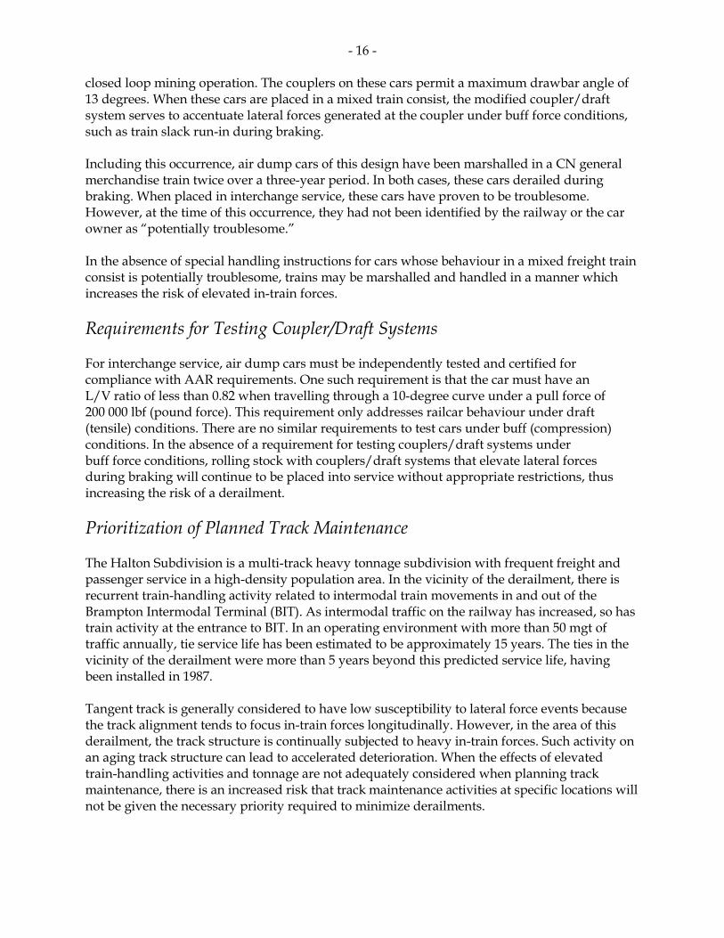
closed loop mining operation. The couplers on these cars permit a maximum drawbar angle of 13 degrees. When these cars are placed in a mixed train consist, the modified coupler/draft system serves to accentuate lateral forces generated at the coupler under buff force conditions, such as train slack run-in during braking. Including this occurrence, air dump cars of this design have been marshalled in a CN general merchandise train twice over a three-year period. In both cases, these cars derailed during braking. When placed in interchange service, these cars have proven to be troublesome. However, at the time of this occurrence, they had not been identified by the railway or the car owner as “potentially troublesome.” In the absence of special handling instructions for cars whose behaviour in a mixed freight train consist is potentially troublesome, trains may be marshalled and handled in a manner which increases the risk of elevated in-train forces. Requirements for Testing Coupler/Draft Systems For interchange service, air dump cars must be independently tested and certified for compliance with AAR requirements. One such requirement is that the car must have an L/V ratio of less than 0.82 when travelling through a 10-degree curve under a pull force of 200 000 lbf (pound force). This requirement only addresses railcar behaviour under draft (tensile) conditions. There are no similar requirements to test cars under buff (compression) conditions. In the absence of a requirement for testing couplers/draft systems under buff force conditions, rolling stock with couplers/draft systems that elevate lateral forces during braking will continue to be placed into service without appropriate restrictions, thus increasing the risk of a derailment. Prioritization of Planned Track Maintenance The Halton Subdivision is a multi-track heavy tonnage subdivision with frequent freight and passenger service in a high-density population area. In the vicinity of the derailment, there is recurrent train-handling activity related to intermodal train movements in and out of the Brampton Intermodal Terminal (BIT). As intermodal traffic on the railway has increased, so has train activity at the entrance to BIT. In an operating environment with more than 50 mgt of traffic annually, tie service life has been estimated to be approximately 15 years. The ties in the vicinity of the derailment were more than 5 years beyond this predicted service life, having been installed in 1987. Tangent track is generally considered to have low susceptibility to lateral force events because the track alignment tends to focus in-train forces longitudinally. However, in the area of this derailment, the track structure is continually subjected to heavy in-train forces. Such activity on an aging track structure can lead to accelerated deterioration. When the effects of elevated train-handling activities and tonnage are not adequately considered when planning track maintenance, there is an increased risk that track maintenance activities at specific locations will not be given the necessary priority required to minimize derailments.
- 17 -
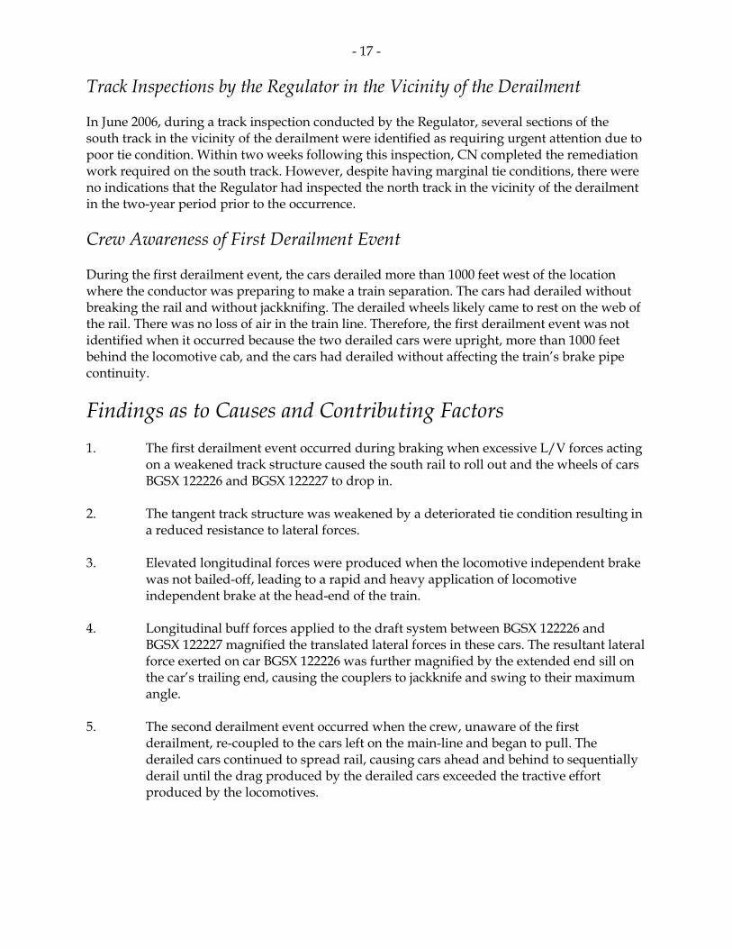
Track Inspections by the Regulator in the Vicinity of the Derailment In June 2006, during a track inspection conducted by the Regulator, several sections of the south track in the vicinity of the derailment were identified as requiring urgent attention due to poor tie condition. Within two weeks following this inspection, CN completed the remediation work required on the south track. However, despite having marginal tie conditions, there were no indications that the Regulator had inspected the north track in the vicinity of the derailment in the two-year period prior to the occurrence. Crew Awareness of First Derailment Event During the first derailment event, the cars derailed more than 1000 feet west of the location where the conductor was preparing to make a train separation. The cars had derailed without breaking the rail and without jackknifing. The derailed wheels likely came to rest on the web of the rail. There was no loss of air in the train line. Therefore, the first derailment event was not identified when it occurred because the two derailed cars were upright, more than 1000 feet behind the locomotive cab, and the cars had derailed without affecting the train’s brake pipe continuity.
Findings as to Causes and Contributing Factors 1. The first derailment event occurred during braking when excessive L/V forces acting
on a weakened track structure caused the south rail to roll out and the wheels of cars BGSX 122226 and BGSX 122227 to drop in.
2. The tangent track structure was weakened by a deteriorated tie condition resulting in
a reduced resistance to lateral forces. 3. Elevated longitudinal forces were produced when the locomotive independent brake
was not bailed-off, leading to a rapid and heavy application of locomotive independent brake at the head-end of the train.
4. Longitudinal buff forces applied to the draft system between BGSX 122226 and
BGSX 122227 magnified the translated lateral forces in these cars. The resultant lateral force exerted on car BGSX 122226 was further magnified by the extended end sill on the car’s trailing end, causing the couplers to jackknife and swing to their maximum angle.
5. The second derailment event occurred when the crew, unaware of the first
derailment, re-coupled to the cars left on the main-line and began to pull. The derailed cars continued to spread rail, causing cars ahead and behind to sequentially derail until the drag produced by the derailed cars exceeded the tractive effort produced by the locomotives.
- 18 -
Findings as to Risk 1. In the absence of special handling instructions for cars whose behaviour in a mixed
freight train consist is potentially troublesome, trains may be marshalled and handled in a manner which increases the risk of elevated in-train forces.
2. In the absence of a requirement for testing couplers/draft systems under buff force
conditions, rolling stock with couplers/draft systems that elevate lateral forces during braking will continue to be placed into service without appropriate restrictions, thus increasing the risk of a derailment.
3. When the effects of elevated train traffic and tonnage are not adequately considered
when planning track maintenance, there is an increased risk that track maintenance activities at specific locations will not be given the necessary priority required to minimize derailments.
Other Findings 1. Despite having marginal tie conditions, there were no indications that the regulator
had inspected the north track in the vicinity of the derailment in the two-year period prior to the occurrence.
2. The first derailment event was not identified when it occurred because the two
derailed cars were upright, more than 1000 feet behind the locomotive cab, and the cars had derailed without affecting the train’s brake pipe continuity.
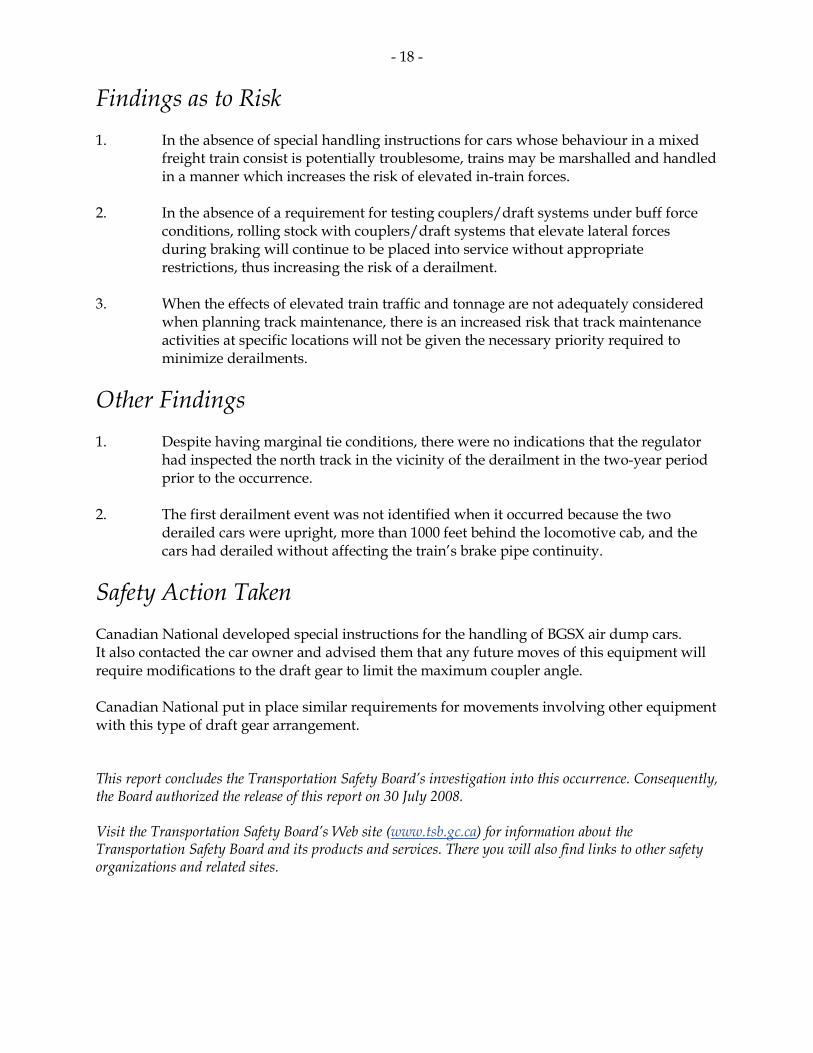
Safety Action Taken Canadian National developed special instructions for the handling of BGSX air dump cars. It also contacted the car owner and advised them that any future moves of this equipment will require modifications to the draft gear to limit the maximum coupler angle. Canadian National put in place similar requirements for movements involving other equipment with this type of draft gear arrangement. This report concludes the Transportation Safety Board’s investigation into this occurrence. Consequently, the Board authorized the release of this report on 30 July 2008. Visit the Transportation Safety Board’s Web site (www.tsb.gc.ca) for information about the Transportation Safety Board and its products and services. There you will also find links to other safety organizations and related sites.
- 19 -
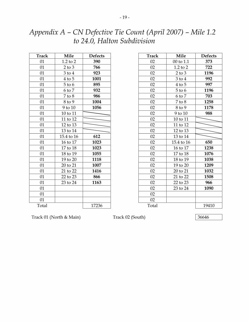
Appendix A – CN Defective Tie Count (April 2007) – Mile 1.2 to 24.0, Halton Subdivision
Track Mile Defects Track Mile Defects
01 1.2 to 2 390 02 00 to 1.1 373 01 2 to 3 766 02 1.2 to 2 722 01 3 to 4 923 02 2 to 3 1196 01 4 to 5 1001 02 3 to 4 992 01 5 to 6 895 02 4 to 5 997 01 6 to 7 932 02 5 to 6 1196 01 7 to 8 986 02 6 to 7 703 01 8 to 9 1004 02 7 to 8 1258 01 9 to 10 1056 02 8 to 9 1178 01 10 to 11 02 9 to 10 988 01 11 to 12 02 10 to 11 01 12 to 13 02 11 to 12 01 13 to 14 02 12 to 13 01 15.4 to 16 612 02 13 to 14 01 16 to 17 1023 02 15.4 to 16 650 01 17 to 18 1023 02 16 to 17 1238 01 18 to 19 1055 02 17 to 18 1076 01 19 to 20 1118 02 18 to 19 1038 01 20 to 21 1007 02 19 to 20 1209 01 21 to 22 1416 02 20 to 21 1032 01 22 to 23 866 02 21 to 22 1508 01 23 to 24 1163 02 22 to 23 966 01 02 23 to 24 1090 01 02 01 02
Total 17236 Total 19410 Track 01 (North & Main) Track 02 (South) 36646