Embed Size (px)
Citation preview
C H A P T E R 9 � R A I L W A Y E L E C T R I F I C A T I O N
395395395395
RAILWAY ELECTRIFICATION
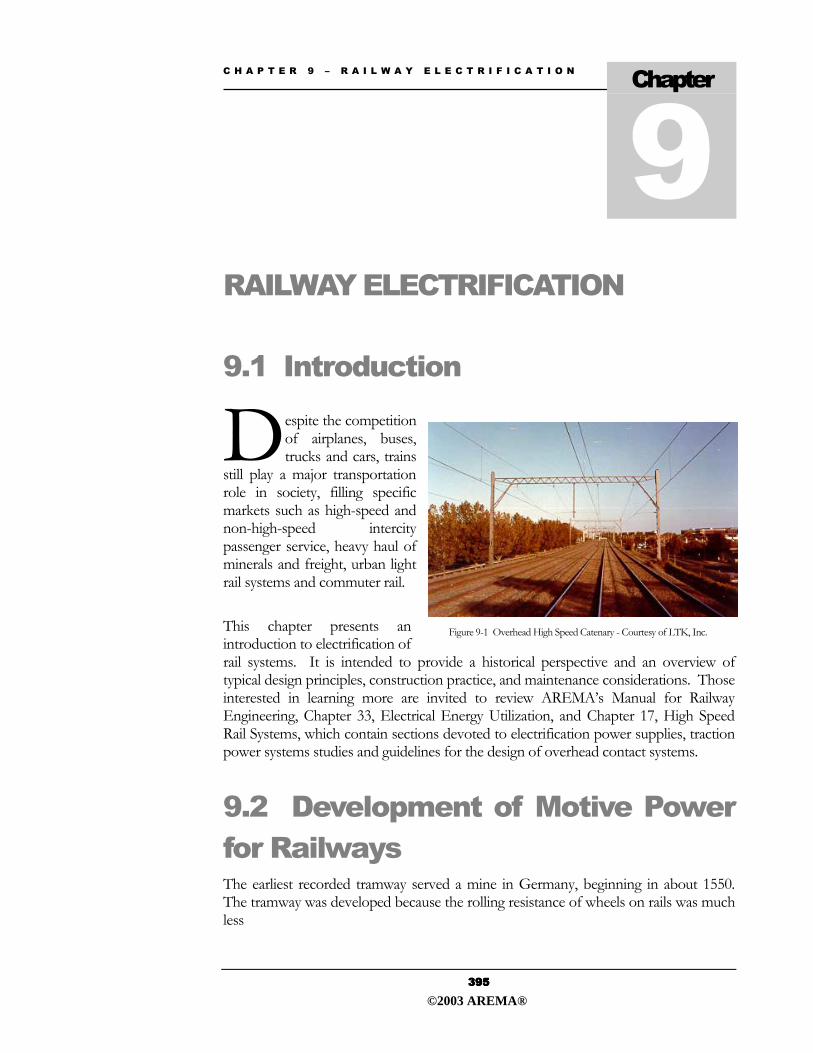
9.1 Introduction espite the competition of airplanes, buses, trucks and cars, trains
still play a major transportation role in society, filling specific markets such as high-speed and non-high-speed intercity passenger service, heavy haul of minerals and freight, urban light rail systems and commuter rail.
This chapter presents an introduction to electrification of rail systems. It is intended to provide a historical perspective and an overview of typical design principles, construction practice, and maintenance considerations. Those interested in learning more are invited to review AREMA�s Manual for Railway Engineering, Chapter 33, Electrical Energy Utilization, and Chapter 17, High Speed Rail Systems, which contain sections devoted to electrification power supplies, traction power systems studies and guidelines for the design of overhead contact systems.
9.2 Development of Motive Power for Railways The earliest recorded tramway served a mine in Germany, beginning in about 1550. The tramway was developed because the rolling resistance of wheels on rails was much less
Chapter
D
Figure 9-1 Overhead High Speed Catenary - Courtesy of LTK, Inc.
©2003 AREMA®
C H A P T E R 9 � R A I L W A Y E L E C T R I F I C A T I O N
406406406406
��Does not create possible electrical safety hazards to the public due to the presence of the bare conductors of the contact system.
When the cost of diesel fuel was 9 cents a gallon and the supply seemed unlimited, United States railways were not interested in alternative methods of propulsion. Railway electrification interest peaks during times of uncertainty in the energy industry. When fuel rose to 34 cents per gallon and the oil embargos occurred, much effort was expended studying alternatives to hydrocarbon fuels. Studies showed that "an estimated 34% savings in energy could be achieved by using electric power. Electrification of just 10% of the (then) present rail trackage (in the densest traffic corridors) could result in a 40% reduction in railway diesel fuel consumption.�
Studies made in the 1970�s also showed that approximately 6 years after electrifying a route, the operating cost would break even when compared to the operating cost of diesel service. At 30 years, the annual operating cost of an electrified system would be one-third that of diesel service. In other words, over the effective life of a railway, the cost to operate a diesel-electric system far exceeds that of an electric system. These increased costs mainly come from the price of fuel and maintenance. Diesel locomotives average 3 to 10 gallons or more of fuel per mile and three times the amount of maintenance of straight electric locomotives.
The most significant aspect arising from these studies is that in order to realize the long-term savings, a huge capital investment is needed. Even when engineering economic studies show that an electrified system would be beneficial, raising enough money to perform the capital upgrade is a daunting challenge. Private railways would most likely require government assistance or financing from the utilities.
9.4.2 Mainline Infrastructure Compatibility
The electrification of a section of existing mainline cannot be undertaken without considering the requirements that the electric locomotives, substations, overhead or third rail power distribution systems and traction return system will place on the existing rail infrastructure.
The more significant issues are noted below:
��Tracks may need to be upgraded, including new track work or re-alignment. Sites must be found and real estate acquired for substations. In rights-of-way with restrictive width, the location of the system-wide ductbank requires coordination with track drainage, the foundations for OCS poles and emergency walkways. In all cases, maintenance access must be provided.
��If DC traction is used, the effects of electrolytic corrosion due to leakage (stray) currents must be mitigated.
©2003 AREMA®
C H A P T E R 9 � R A I L W A Y E L E C T R I F I C A T I O N
407407407407
��Additional clearance may need to be provided in tunnels and at bridges. Existing civil structures may have insufficient clearance to accommodate the proposed electrification system. It may be necessary to lower tracks through overhead crossing bridges. New bridges resulting from grade-crossing elimination will need to be built with adequate electrical clearance. Future widening of existing overhead bridges must be considered.
��Tunnels may be suitable for electrification, or may require costly remedial work, enlargement or �daylighting.�
��Integration of the electrification support structures with existing station canopies must be considered. Station canopies that project over platform edges may need modification.
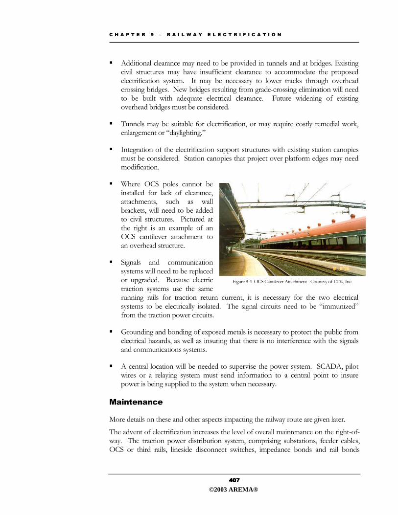
��Where OCS poles cannot be installed for lack of clearance, attachments, such as wall brackets, will need to be added to civil structures. Pictured at the right is an example of an OCS cantilever attachment to an overhead structure.
��Signals and communication systems will need to be replaced or upgraded. Because electric traction systems use the same running rails for traction return current, it is necessary for the two electrical systems to be electrically isolated. The signal circuits need to be �immunized� from the traction power circuits.
��Grounding and bonding of exposed metals is necessary to protect the public from electrical hazards, as well as insuring that there is no interference with the signals and communications systems.
��A central location will be needed to supervise the power system. SCADA, pilot wires or a relaying system must send information to a central point to insure power is being supplied to the system when necessary.
Maintenance
More details on these and other aspects impacting the railway route are given later.
The advent of electrification increases the level of overall maintenance on the right-of-way. The traction power distribution system, comprising substations, feeder cables, OCS or third rails, lineside disconnect switches, impedance bonds and rail bonds
Figure 9-4 OCS Cantilever Attachment - Courtesy of LTK, Inc.
©2003 AREMA®
C H A P T E R 9 � R A I L W A Y E L E C T R I F I C A T I O N
425425425425
urban areas, the structures are often relegated to sidewalks. To help the structures fit into the urban environment, the structures will often serve double duty by acting as light poles, traffic signal poles, etc. On straight or slightly curved track, either cantilevers or cross-spans support the trolley wire such that it is placed over the center of the track. When the track requires tight curves, the trolley wire is held in place with cross-spans, pull-offs and back bones. Although trolley poles pivot at the base, the trolley harp does not pivot so that the trolley wire must be placed towards the center of the curve on sharp curves to allow the trolley shoe to track efficiently. The trolley shoe must be drawn tangentially along the trolley wire, thereby not rubbing against the �cheeks� of the groove. Only by using rigid harps can the trolley shoe diverge onto the correct trolley wire at turnouts, as the pole operates passively being positioned only by the direction of the streetcar on its tracks.
Catenary Systems
Two-wire systems are referred to as simple catenary and utilize a contact wire and above it, a messenger wire. The messenger wire serves two purposes (1) to support the contact wire vertically between structures by use of hangers and (2) to provide more electrical conductivity.
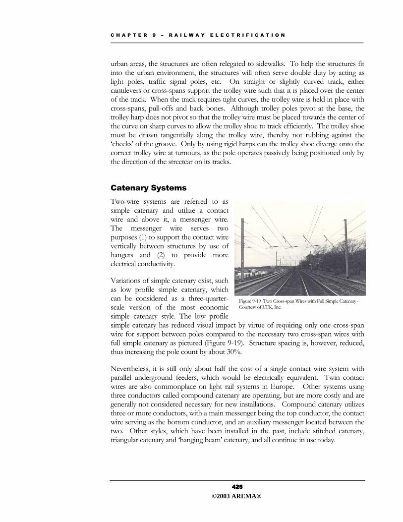
Variations of simple catenary exist, such as low profile simple catenary, which can be considered as a three-quarter-scale version of the most economic simple catenary style. The low profile simple catenary has reduced visual impact by virtue of requiring only one cross-span wire for support between poles compared to the necessary two cross-span wires with full simple catenary as pictured (Figure 9-19). Structure spacing is, however, reduced, thus increasing the pole count by about 30%.
Nevertheless, it is still only about half the cost of a single contact wire system with parallel underground feeders, which would be electrically equivalent. Twin contact wires are also commonplace on light rail systems in Europe. Other systems using three conductors called compound catenary are operating, but are more costly and are generally not considered necessary for new installations. Compound catenary utilizes three or more conductors, with a main messenger being the top conductor, the contact wire serving as the bottom conductor, and an auxiliary messenger located between the two. Other styles, which have been installed in the past, include stitched catenary, triangular catenary and �hanging beam� catenary, and all continue in use today.
Figure 9-19 Two Cross-span Wires with Full Simple Catenary -Courtesy of LTK, Inc.
©2003 AREMA®
C H A P T E R 9 � R A I L W A Y E L E C T R I F I C A T I O N
426426426426
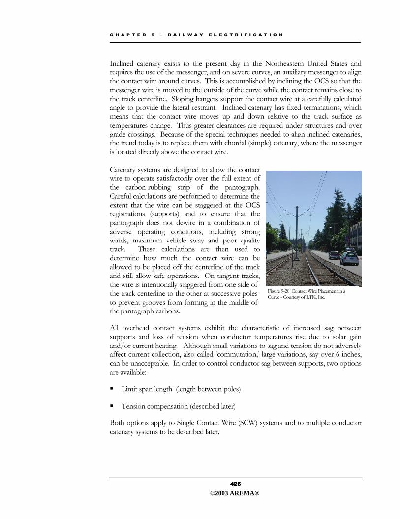
Inclined catenary exists to the present day in the Northeastern United States and requires the use of the messenger, and on severe curves, an auxiliary messenger to align the contact wire around curves. This is accomplished by inclining the OCS so that the messenger wire is moved to the outside of the curve while the contact remains close to the track centerline. Sloping hangers support the contact wire at a carefully calculated angle to provide the lateral restraint. Inclined catenary has fixed terminations, which means that the contact wire moves up and down relative to the track surface as temperatures change. Thus greater clearances are required under structures and over grade crossings. Because of the special techniques needed to align inclined catenaries, the trend today is to replace them with chordal (simple) catenary, where the messenger is located directly above the contact wire. Catenary systems are designed to allow the contact wire to operate satisfactorily over the full extent of the carbon-rubbing strip of the pantograph. Careful calculations are performed to determine the extent that the wire can be staggered at the OCS registrations (supports) and to ensure that the pantograph does not dewire in a combination of adverse operating conditions, including strong winds, maximum vehicle sway and poor quality track. These calculations are then used to determine how much the contact wire can be allowed to be placed off the centerline of the track and still allow safe operations. On tangent tracks, the wire is intentionally staggered from one side of the track centerline to the other at successive poles to prevent grooves from forming in the middle of the pantograph carbons.
All overhead contact systems exhibit the characteristic of increased sag between supports and loss of tension when conductor temperatures rise due to solar gain and/or current heating. Although small variations to sag and tension do not adversely affect current collection, also called �commutation,� large variations, say over 6 inches, can be unacceptable. In order to control conductor sag between supports, two options are available:
��Limit span length (length between poles)
��Tension compensation (described later)
Both options apply to Single Contact Wire (SCW) systems and to multiple conductor catenary systems to be described later.
Figure 9-20 Contact Wire Placement in a Curve - Courtesy of LTK, Inc.
©2003 AREMA®
C H A P T E R 9 � R A I L W A Y E L E C T R I F I C A T I O N
434434434434
9.8 Electrification Interfaces with Other Rail Elements When an established railway is to be electrified, there can be significant engineering and operational impacts on the existing infrastructure. The more significant impacts involve:
��Right-of-Way
��Track Structure
��Civil Structures
��Signaling and Communications
9.8.1 Right-of-Way
Track Layout/Realignment It is desirable that track alignment and modifications to track crossovers and turnouts be completed before route electrification occurs. Additionally, track renewals and track lowering measures, as described below, should have been finished. Future track improvements may need to be accelerated to avoid the need for later changes. Old redundant track should be removed before initiating electrification so that cranes are not impeded by the presence of high voltage catenary wires, conductor rails or cables.
Substations
Typically, 25kV substations require a site area of about an acre in size, with road access suitable for trucks delivering the largest piece of substation equipment. DC substations are smaller, ranging in size from 2000 to 5000 square feet, but are generally more numerous than AC substations.
Supporting Structures for the Contact System
On existing main line routes, particularly those with more than two tracks, there will probably not be enough room between tracks to install OCS pole foundations. Therefore, the poles will be allocated to the outside of the line. The right-of-way needs to be examined to insure that structures and any supporting back guys fall within the
©2003 AREMA®
C H A P T E R 9 � R A I L W A Y E L E C T R I F I C A T I O N
435435435435
ROW without impeding drainage. Since third rail is attached to the end of the ties, ROW limits are not as critical for third rail systems as for overhead systems.
Systemwide Ductbanks
Ductbanks are required for power distribution cables and should be designed to accommodate new signal or communication cables, should existing aerial signal and communication cables need replacement. The location of parallel track and cross-track ductbanks will need to be coordinated with drainage pipes, foundations for signals and OCS poles, and emergency walkways.
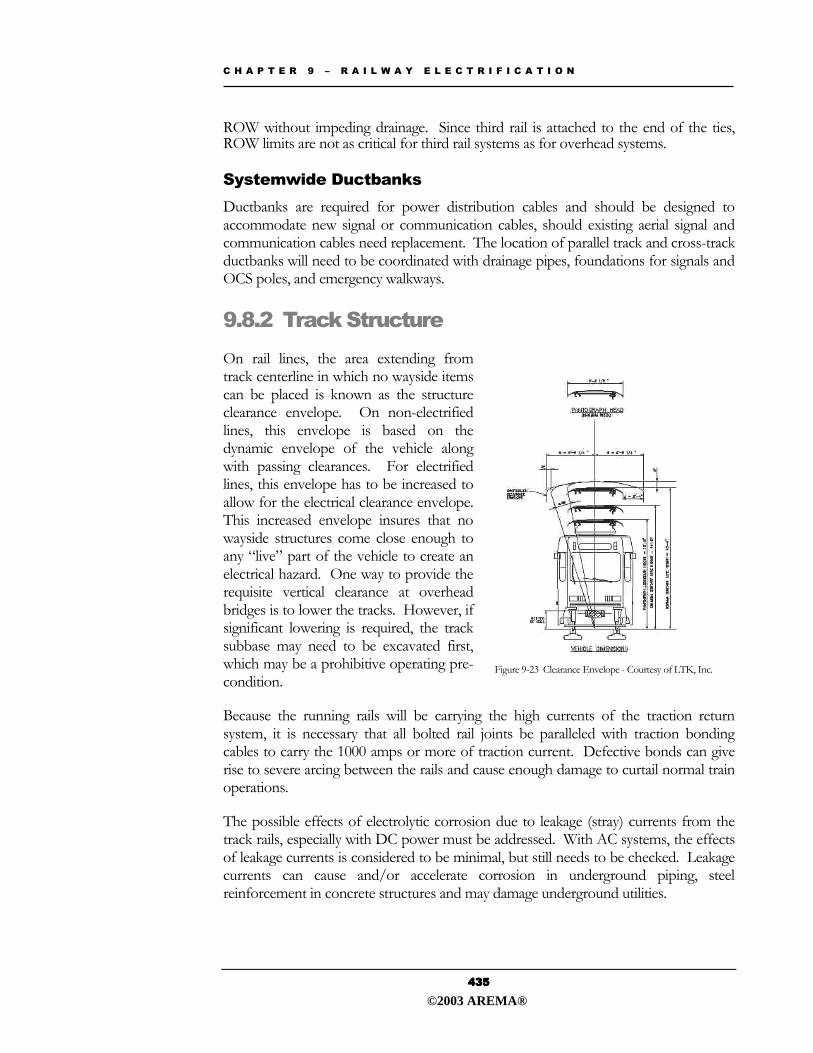
9.8.2 Track Structure On rail lines, the area extending from track centerline in which no wayside items can be placed is known as the structure clearance envelope. On non-electrified lines, this envelope is based on the dynamic envelope of the vehicle along with passing clearances. For electrified lines, this envelope has to be increased to allow for the electrical clearance envelope. This increased envelope insures that no wayside structures come close enough to any �live� part of the vehicle to create an electrical hazard. One way to provide the requisite vertical clearance at overhead bridges is to lower the tracks. However, if significant lowering is required, the track subbase may need to be excavated first, which may be a prohibitive operating pre-condition.
Because the running rails will be carrying the high currents of the traction return system, it is necessary that all bolted rail joints be paralleled with traction bonding cables to carry the 1000 amps or more of traction current. Defective bonds can give rise to severe arcing between the rails and cause enough damage to curtail normal train operations.
The possible effects of electrolytic corrosion due to leakage (stray) currents from the track rails, especially with DC power must be addressed. With AC systems, the effects of leakage currents is considered to be minimal, but still needs to be checked. Leakage currents can cause and/or accelerate corrosion in underground piping, steel reinforcement in concrete structures and may damage underground utilities.
Figure 9-23 Clearance Envelope - Courtesy of LTK, Inc.
©2003 AREMA®