Embed Size (px)
Citation preview

BC MoTI SUPPLEMENT TO TAC GEOMETRIC DESIGN GUIDE MoTI Section 1100 TAC Section Not Applicable
July, 2014 Page 1100-i
1100 RAILWAY CROSSINGS & UTILITIES CHAPTER
1110 RAILWAY CROSSINGS
1110.01 GENERAL ........................................................................................................................... 1110‐1 1110.02 SUMMARY OF RESPONSIBILITY CENTRES FOR RAILWAY CROSSING ISSUES .................... 1110‐2 1110.03 OVERVIEW OF LEVEL RAILWAY CROSSINGS ..................................................................... 1110‐3 1110.04 JURISDICTION AND ADMINISTRATIVE LEVELS
AND TYPES OF RAILWAY CROSSINGS ............................................................................... 1110‐5 1110.05 SUMMARY OF RESPONSIBILITIES OF ADMINISTRATION
OF LEVEL RAILWAY CROSSINGS ........................................................................................ 1110‐6 1110.06 TYPES OF WORKS, OPERATIONAL CHANGES, AND
STATUS CHANGES AT RAILWAY CROSSINGS .................................................................... 1110‐7 1110.07 APPROVALS FOR WORKS OR STATUS CHANGES AT RAILWAY CROSSINGS ...................... 1110‐8 1110.08 CONSTRUCTION COSTS AND GRANTS RESPONSIBILITIES AT
LEVEL RAILWAY CROSSINGS ............................................................................................. 1110‐9 1110.09 LEVEL RAILWAY CROSSING CONSTRUCTION APPLICATION REQUIREMENTS ................ 1110‐10 1110.10 TYPES OF CROSSING SIGNALS AND SIGNAGE ................................................................. 1110‐12 1110.11 CLEAR VIEW TRIANGLE ................................................................................................... 1110‐15 1110.12 LEVEL RAILWAY CROSSING SURFACE SELECTION ........................................................... 1110‐17 1110.13 TYPES OF LEVEL RAILROAD CROSSINGS ......................................................................... 1110‐18 1110.14 PUBLIC NOTICE EXAMPLE ............................................................................................... 1110‐19
1120 POLE RELOCATIONS
1120.01 GENERAL ........................................................................................................................... 1120‐1 1120.02 RECOMMENDED GUIDELINES FOR POLE LOCATIONS ..................................................... 1120‐1 1120.03 EXCEPTIONS TO HORIZONTAL OR VERTICAL CLEARANCES .............................................. 1120‐1 1120.04 RELOCTION OF UTILITY POLES .......................................................................................... 1120‐1 1120.05 RELOCATION COSTS OF UTILITY POLES ............................................................................ 1120‐1

SUPPLEMENT TO TAC GEOMETRIC DESIGN GUIDE BC MoTI MoTI Section 1100 TAC Section Not Applicable
Page 1100-ii July, 2014
1100 RAILWAY CROSSINGS & UTILITIES CHAPTER ‐ FIGURES
1110 RAILWAY CROSSINGS
FIGURE 1110.A SAMPLE LEVEL CROSSING APPLICATION LAYOUT .................................................... 1110‐20 FIGURE 1110.B TYPICAL CROSSING SECTIONS .................................................................................. 1110‐21 FIGURE 1110.C TYPICAL CROSS SECTIONS ......................................................................................... 1110‐22 FIGURE 1110.D TYPICAL CROSS SECTIONS CONTINUED .................................................................... 1110‐23 FIGURE 1110.E CLEAR VIEW TRIANGLE REQUIREMENTS .................................................................. 1110‐24 FIGURE 1110.F TYPICAL DETAIL FOR CROSSING SIGNALS ................................................................. 1110‐25 FIGURE 1110.G TYPICAL DETAIL FOR CROSSING WITH GATES .......................................................... 1110‐26
1120 POLE RELOCATIONS
FIGURE 1120.A UTILITY POLE LEGEND SAMPLE................................................................................... 1120‐2

BC MoTI SUPPLEMENT TO TAC GEOMETRIC DESIGN GUIDE MoTI Section 1110 TAC Section Not Applicable
July, 2014 Page 1110-1
1110 RAILWAY CROSSINGS
1110.01 GENERAL Any roadworks that revise, reconstruct, or relocate an existing crossing, or create a new crossing, must be approved by the appropriate Federal or Provincial Regulatory bodies. This approval process is co‐ordinated through the Rail, Navigable Waters Specialist of Engineering Branch, in Headquarters. The principal contact is:
Rail, Navigable Waters Specialist HQ Engineering Branch c/o Kevin Baskin, Chief Bridge Engineer Mailing address; PO Box 9850 Stn Prov Govt Victoria BC V8W 9T5 Physical address; 4B ‐ 940 Blanshard Street Victoria BC V8W 3E6 Email: [email protected] Ph: 387‐7737 Fax: 387‐7735
Drawings: A special purpose drawing, called an "Application Layout" drawing, must be prepared to accompany an application for new at‐grade railway crossings, as well as reconstruction, relocation, or revision of an existing crossing. Drawing information and crossing requirements shall be in accordance with sample Figure 1110.A, at the end of this section. Clear view lines are a function of railway speed and roadway speed. Refer to Section 1110.11 and Figure 1110.E for the roadway and railway approach distances respectively. It is expected that all road design issues will meet the requirements of the BC Ministry of Transportation Supplement to TAC Geometric Design Guide.
Time Frames: For simple crossing revisions, that require no action or work by the Railway, other than approval, and where all costs are being borne by the Ministry, approvals to proceed can take at least 3 months. For crossings requiring track work the process can take at least 5 months. For crossings requiring significant railway signal work, the process can take at least 10 months. For any crossings where grants and/or cost sharing are required (to be determined by the Rail, Navigable Waters Specialist), the process can take 6 months at the very least. Read the rest of this section to familiarize yourself with the background, process and guidelines. Prologue: This standard provides guidance in level railway crossing design and also provides information that will help you decide whether it is possible to construct a public crossing at a specific site. It is not the intention of this section to promote the construction of new crossings but to ensure that necessary crossings are designed to the latest standards. Poorly conceived crossings may create safety concerns not only at the crossing, but also to the road network directly adjacent to the crossing.
SUPPLEMENT TO TAC GEOMETRIC DESIGN GUIDE BC MoTI MoTI Section 1110 TAC Section Not Applicable
Page 1110-2 July, 2014
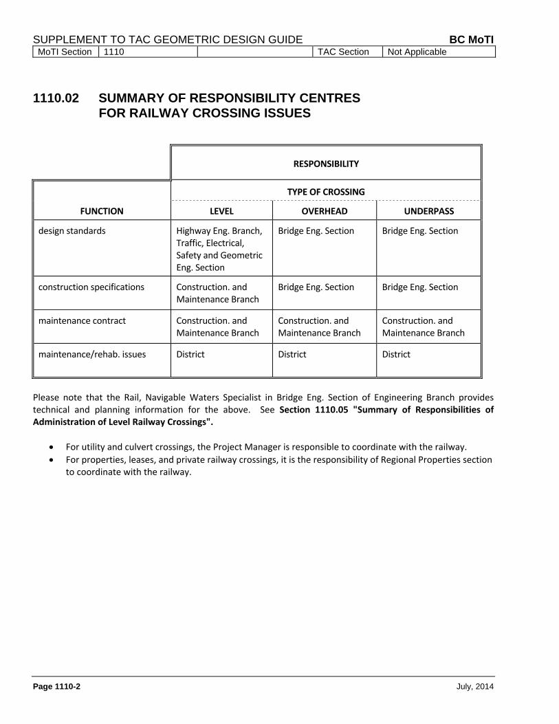
1110.02 SUMMARY OF RESPONSIBILITY CENTRES FOR RAILWAY CROSSING ISSUES
RESPONSIBILITY
FUNCTION
TYPE OF CROSSING
LEVEL OVERHEAD UNDERPASS
design standards Highway Eng. Branch, Traffic, Electrical, Safety and Geometric Eng. Section
Bridge Eng. Section Bridge Eng. Section
construction specifications Construction. and Maintenance Branch
Bridge Eng. Section Bridge Eng. Section
maintenance contract Construction. and Maintenance Branch
Construction. and Maintenance Branch
Construction. and Maintenance Branch
maintenance/rehab. issues District District District
Please note that the Rail, Navigable Waters Specialist in Bridge Eng. Section of Engineering Branch provides technical and planning information for the above. See Section 1110.05 "Summary of Responsibilities of Administration of Level Railway Crossings".
For utility and culvert crossings, the Project Manager is responsible to coordinate with the railway.
For properties, leases, and private railway crossings, it is the responsibility of Regional Properties section to coordinate with the railway.
BC MoTI SUPPLEMENT TO TAC GEOMETRIC DESIGN GUIDE MoTI Section 1110 TAC Section Not Applicable
July, 2014 Page 1110-3
1110.03 OVERVIEW OF LEVEL RAILWAY CROSSINGS
The history of railways in British Columbia predates most of the Province's roads. Many railways were in operation before vehicles were manufactured. As a result, during the initial railway and roadway construction, engineering was not concerned with the intricacies of crossing design. The advent of vehicles, and larger and faster trains, leaves many of the existing crossings poorly located and designed. INCOMPATIBLE MODES OF TRANSPORTATION Physical differences between railway operating equipment and roadway operating equipment lead to conflicts because of the manner in which they operate. Railway equipment, which tends to be very heavy, large, and therefore not very adaptable to directional and speed changes, require rigidly set operating rules and timetables. A train cannot vary direction and is on a two way path which requires coordinated movements. The rules and timetables tend to dictate when and how the equipment is operated. Therefore, the employees are trained in a strict manner to ensure safe operations. Railway equipment is, for the most part, well maintained to a specific operational standard. Since a breakdown can lead to the closure of the trackage, equipment tests are performed regularly. Roadway equipment, which is comparatively light, manoeuvrable and can vary speed rapidly, have only operational guidelines which limit speed and provide directional rules. The rules and speed limits tend to only emphasize maximum operational limits. Steerage is controlled by the operator. Vehicular operators are given a test which judges adaptability and can therefore, be subjective or change after a license is granted. Since vehicles are privately owned and must be adaptable for the operator's varied usage, the condition and characteristics can vary tremendously from vehicle
to vehicle. Road conditions can also vary the operational characteristics of vehicles. Right of passage for trains at level crossings has been an operational fact since cars were invented. Therefore, operators on roadways must vary operation when a crossing is occupied, or about to be occupied, by rail equipment. From a practical standpoint, it is preferable for a train to continue unabated. Crossing occupancy time is reduced in this manner. Determination of crossing safety must be made by the driver each and every time a crossing is approached. In order to allow this decision to be rendered without distraction, the crossing should have clear sightlines to the rail approaches and/or signals. The crossing should have forgiving and smooth horizontal and vertical alignments, laning and number of tracks clearly marked to avoid confusion. Roadside clutter, lane changing, nearby intersections and congestion can also lead to driver distraction. Wherever possible, a crossing and approaches should be designed to provide the driver with only that information required for safe passage. STRUCTURAL DIFFERENCES Railway equipment travels on ribbons of steel attached to ties which are on a "roadbed". The wheel flange rides on the inside or gauge side of the rail which maintains alignment and also maintains the railway equipment's ability to travel on the railway. These rails are approximately six to seven inches high. Due to the sizes and weights of railway equipment, the alignments and grades of the railway are not very flexible. Roadway equipment travels on a paved or prepared gravel surface. This allows vehicles of various sizes and characteristics to travel a common route.

SUPPLEMENT TO TAC GEOMETRIC DESIGN GUIDE BC MoTI MoTI Section 1110 TAC Section Not Applicable
Page 1110-4 July, 2014
The crossing is a discontinuation of the normal road and rail roadbed structures. The requirement for a flangeway on the inside of the rails disrupts the continuous roadway surface. This "gap" increases the roughness of the roadway. Since the ties, supporting the rail, move up and down with the impacts and weights of the rail traffic, it is difficult to maintain a structurally sound surface in smooth condition. Maintenance difficulties arise out of the operational and physical differences at level crossings. All work must be scheduled and coordinated so it does not conflict with the operation requirements of either facility. The physical differences generally make repairs inaccessible for either party. For example, the railway cannot run a continuous re‐ballasting program through a level crossing without close coordination with the road authority. Conversely, the road authority cannot continue a paving program through a crossing without close coordination with the rail authority. As an example, both these programs may require raising the elevation of the crossing. This would be reflected in the approach gradients and may be restricted by other facilities (i.e. bridges, underpasses, intersections and drainage patterns) whose elevations may be fixed. Underground utility maintenance necessary for the safety and operation of either road or rail may also be inconvenient. Drainage problems are caused on the roadway surface by the flangeway or the grade and crossfall of the railway. The flangeway acts like a flue collecting surface runoff and depositing it on the railway track adjacent to the crossing disturbing the integrity of the rail bed. A break in road profile can cause water and debris to collect on the roadway. Integrity of the road surface and railway are difficult to maintain. A variety of forces all act to varying degrees at every crossing. Impacts of road traffic on the rail and pavement "creep" can break, overturn and move rails so they no longer function at a safe standard. Train impact loading and rail "creep" can pull and crack the road surface, which can cause an unsafe crossing condition for motorists.
LEGAL CONSIDERATIONS Level crossings, by their very nature, are considered to be amongst the most expensive section of roadway per square meter to construct and maintain. The liabilities can also be amongst the most severe, especially when safety considerations of a proposal or maintenance is not given the highest priority. The strength of a liability claim increases through incompetence and negligence. When inspecting a facility or considering routes, a brief rationalization of the alternatives, considerations and effects must be made. If a fault is found, it must be acted on in a response time that is expedient and reasonable. Inspections must be carried out at intervals, which reflect the usage, history and importance of the crossing. The right of passage, which permitted the installation of the crossing by either party, usually in the form of an Agreement, Order or Certificate, indicates that a crossing is maintained in accordance with various Railway Acts and the Regulations pursuant thereto. Both railway and roadway authorities have a legal duty to ensure crossing safety. TODAY'S PRACTICES In order to reflect the developing technology of modern level railway crossings, many of the old crossings should be re‐evaluated to determine their future prospects and alternatives (remedial measures) to provide an effective investment.

BC MoTI SUPPLEMENT TO TAC GEOMETRIC DESIGN GUIDE MoTI Section 1110 TAC Section Not Applicable
July, 2014 Page 1110-5
1110.04 JURISDICTION AND ADMINISTRATIVE LEVELS AND TYPES OF RAILWAY CROSSINGS
Two Charters control various railway crossings by means of Acts, Regulations and/or policies. The following table indicates the appropriate charter.
FEDERAL CHARTER PROVINCIAL CHARTER
Railway Companies
Burlington Northern Santa Fe Railway Canadian National Railway Canadian Pacific Railway Kettle Falls International Railway
British Columbia Railway (Port Subdivision) Canadian Forest Products Railway Canfor Englewood Logging Division Southern Railway of BC various logging railways industrial/resource spurs
Acts and Regulations
Canadian Transportation Act Railway Safety Act Railway Crossing and Relocation Act Supporting standards and regulations
Canadian Transportation Act (specific sections) Railway Safety Act (specific sections) Federal Standards and Regulations (specific sections)
Administrative Levels of Railway Crossings
Three basic administrative levels of railway crossings exist. 1) Unrestricted or Public railway crossings are
generally recognized as public roads or walkways intersecting a railway.
2) Restricted or Private railway crossings
(temporary or permanent) are generally vehicular or pedestrian crossings with controlled access, serving only one facility or property.*
3) Farm railway crossings allow farmers continued
access to their lands which were severed by the railway.*
Types of Railway Crossings
Three physical types of railway crossings exist. 1) The most common crossing, because of initial
cost and level of engineering involved, is at grade and is most commonly referred to as a level crossing.
2) The second most common crossing is the
roadway overhead structure (road over rail). Since the highway has more flexible horizontal and vertical alignments, this is the most popular grade separated crossing.
3) The roadway underpass structure (road under
rail) is preferable when the railway is on a fill or near an escarpment, allowing easy passage of the roadway under the trackage with minimal structure size.
*Restricted (or Private) and Farm crossings are not covered in this section and are not administered by the Rail, Navigable Waters Specialist. Engineering considerations for Restricted (or Private) and Farm crossings can be similar to minor public roads.

SUPPLEMENT TO TAC GEOMETRIC DESIGN GUIDE BC MoTI MoTI Section 1110 TAC Section Not Applicable
Page 1110-6 July, 2014
1110.05 SUMMARY OF RESPONSIBILITIES OF ADMINISTRATION OF LEVEL RAILWAY CROSSINGS
Function Specific Function Responsibility Area
1. Identify need a) increase road capacity
or convenience
Area Manager/District/Region
b) increase safety Area Manager/District
(Fed/Prov) Agencies responsible for administering the Railway Acts
Railway company
Rail, Navigable Waters Specialist
2. Develop plan and proposal Area Manager/District/ Region/Design company
3. Communication for facility/clearance provisions with railway/regulatory agencies
Rail, Navigable Waters Specialist
4. Allocate funds Area Manager/District/Region/Rail, Navigable Waters Specialist
5. Engineering a) ‐ Level crossings Area Manger/District/ Region/Design company
b) ‐ Railway signals Railway company
c) – Traffic lights, signals Regional Traffic Engineer
6. Application and Negotiation Rail, Navigable Waters Specialist
7. Agreement by Rail and Road Authorities
Rail, Navigable Waters Specialist
8. Approval (Order, Decision etc.)
(Fed/Prov) Agencies responsible for administering the Railway Acts
9. Maintenance work in accordance with approval; work is carried out by:
Highway Approaches = road authority
Signals = railway company
Crossing Surface = as arranged
BC MoTI SUPPLEMENT TO TAC GEOMETRIC DESIGN GUIDE MoTI Section 1110 TAC Section Not Applicable
July, 2014 Page 1110-7
1110.06 TYPES OF WORKS, OPERATIONAL CHANGES, AND STATUS CHANGES AT RAILWAY CROSSINGS
TYPES OF WORKS Eight basic types of railway works are defined although some activities on existing crossings combine more than one type.
1) Construction of a new public crossing.
2) Alteration of a crossing including works which vary geometry or dimension of the crossing (within 10 metres of trackage or modifying road/rail approaches that may impact stopping, signal or crossing sight distances) such as revising the alignment, adding track switches, multiple tracks or adding a sidewalk.
3) Reconstruction of a level crossing usually indicates that an existing crossing is to be totally renewed without substantial alteration.
4) Relocation of a level crossing is usually done to upgrade a section of road or replace an unsafe crossing with one at a more suitable site.
5) Removal or closure of an existing crossing. Road closure or railway abandonment.
6) Signalization of a crossing indicates that some form of an active warning or protective device has been installed at a level crossing.
7) Interconnection/pre‐emption modification to a railway or traffic signal will require a review by the Regional Traffic Engineer of the timing sheets and may require modifications to signal operations to maintain a safe crossing environment. Prior to signal/sign reconfiguration, the effect to crossing safety must be evaluated by the Regional Traffic Engineer.
8) Maintenance work is a repair or partial renewal to an existing crossing or signal to provide safe and unencumbered passage.
OPERATIONAL CHANGES Operational changes including speed changes (rail or road), lane reconfiguration or changing direction, increasing volumes due to other factors such as development, detours etc. and whistling cessation.
STATUS CHANGES Status Changes include changes in:
a) road authority b) jurisdiction c) maintenance responsibilities.

SUPPLEMENT TO TAC GEOMETRIC DESIGN GUIDE BC MoTI MoTI Section 1110 TAC Section Not Applicable
Page 1110-8 July, 2014
1110.07 APPROVALS FOR WORKS OR STATUS CHANGES AT RAILWAY CROSSINGS
These are the actions/approvals required before undertaking railway works and status changes.
RAILWAY WORKS/STATUS CHANGES REGULATORY ACTIONS REQUIRED
Construction Public notice/Agreement/Order
Alteration Public notice/Agreement/Order
Reconstruction Notify Railway
Relocation Public notice/Agreement/Order
Removal or closure Notify Railway*
Signalization Public notice/Agreement/Order
Interconnection/pre‐emption Notify Railway
Maintenance Notify Railway
Operational Public notice/Agreement/Safety study
Status Agreement/Order
NOTE: Public notices are to be forwarded to landowners immediately abutting the crossing works at least 60 days before the work commences. See Section 1110.14 for a Public Notice Example. * May require Agreement, Order or Certificate if not in connection with a relocation or not included in an Agreement, Order or Certificate for related work. Federal Grant monies may be available through the Rail, Navigable Waters Specialist. If an agreement between the Road Authority and a Federally‐Regulated Railway is not possible due to a dispute over cost, location or design, a Decision by the Canadian Transportation Agency (CTA) may be required. An Environmental Assessment, in accordance with the Canadian Environment and Assessment Act, may be required to allow the CTA to issue a Decision or Order. The CTA may be able to help the parties resolve the issues through its mediation process before a Decision is rendered. An Environmental Assessment would not be required if the dispute is resolved through mediation. Projects may have other Canadian Environment and Assessment Act triggers.

BC MoTI SUPPLEMENT TO TAC GEOMETRIC DESIGN GUIDE MoTI Section 1110 TAC Section Not Applicable
July, 2014 Page 1110-9
1110.08 CONSTRUCTION COSTS AND GRANTS RESPONSIBILITIES AT LEVEL RAILWAY CROSSINGS
The following table describes the basic responsibilities in accordance with activity:
ACTIVITY FEATURE COST TO WORK DONE OR
DIRECTED BY
WORK PROTECTION REQUIRED
Level Crossing Surface Per Agreement or Order
Rail & Road Rail & Road
Road Approach Road* Road Road & Rail within 10 m of Rail
Construction & Maintenance
Rail Approach Rail* Rail Road & Rail Shoulder to Shoulder
Road Culvert/Ditches on road right‐of‐way
Road* Road Road & Rail within 10 m of Rail
Rail Culvert/Ditches on railway right‐of‐way
Rail* Rail Road & Rail Shoulder to Shoulder
RR Whistle Post/Flange Sign
Rail Rail None
RR Crossing Sign "Crossbuck" /Number of Tracks Signs
Rail Rail None
Installation & Maintenance
Stop Sign/Stop Ahead Sign Road* Road None
Railway Crossing Advance Warning Sign
Road Road None
Rail Signals Per Agreement or Order
Rail Rail & Road
* Unless otherwise ordered or agreed.
Crossing must be public for at least three years and be eligible for Federal Funding, after determination by Transport Canada, for a safety enhancement. Cross‐product (trains per day X vehicles per day) should be over 1,000 to have a chance of receiving federal grants for up to 50% of eligible works.
If the road authority is senior in a Municipality, City, Town or Village, the road authority shall pay maintenance costs of the crossing surface beyond the original highway right‐of‐way width.
Please note: Supply and installation of rail, ties, plates, spikes, etc. are a railway maintenance (work) and cost responsibility [Canadian Transportation Agency Decision No. 642‐R‐2003, Railway‐Highway Crossing at Grade Regulations (SOR/80‐748)]. Pavement removal, flagging, public notice, crossing surface materials, grading and repaving are Road Authority responsibility with costs being the responsibility of the junior party or as directed in the Order/Agreement. There can be incremental track costs to accommodate crossings (i.e. longer ties, rail size increases, etc.) for the rehabilitation/reconstruction of a railway crossing that can be invoiced to the Road Authority.
SUPPLEMENT TO TAC GEOMETRIC DESIGN GUIDE BC MoTI MoTI Section 1110 TAC Section Not Applicable
Page 1110-10 July, 2014
1110.09 LEVEL RAILWAY CROSSING CONSTRUCTION APPLICATION REQUIREMENTS
Level Railway Crossing Construction Approval Procedures
For the re/construction of railway crossings, a drawing should be completed, as shown on sample layout Figure 1110.A, and forwarded to the Rail, Navigable Waters Specialist. Drawings in PDF format are preferred. Some information, which cannot normally be included on the drawing, is required for the application. Please advise of:
the proposed date of commencement and the projected time for completion of the works;
the roadway speed limit; and
the number of vehicles per day and type of traffic (school buses, logging trucks, bicycles, etc.).
NOTE: Every reasonable attempt must be made to meet the standards. It is required that the design engineer apply for Federal Minister exemption (or delegates) for those crossing elements that do not meet the Federal Standards. Chief Engineer’s signoff is required for design elements that do not meet these standard requirements. For reconstruction, safety improvements will be favourably considered even if not all design elements meet standard design requirements.
Road-Railway Crossing Requirements
Note: If tracks are more than 30.5 metres (100 feet) apart they should be considered as separate crossings. If vehicle queuing between tracks comes within 5 metres of any track, it should be considered a single crossing.
Overhead luminaires should be installed when an unsignalised crossing has any of the following conditions:
train switching movements at the crossing;
spur crossing in urban areas;
vehicle headlights do not illuminate the crossing due to approach alignments and grades.
Railway crossing signals shall be required if:
within three years of opening, the cross‐product (trains per day times vehicles per day) is 1000 or over;
sight‐lines are inadequate (see Section 1110.11);
the tangential direction of the road alignment at any point within the desirable distance from the crossing (specified in Table A of Section 1110.11) is more acute than a 70 degree intersection angle with the railway;
there is a pedestrian/cyclist crossing of two or more tracks where trains can pass each other;
the centre line of a pedestrian/cyclist crossing is more than 3.6 metres (12 feet) from a road crossing signal.
A level railway crossing, road intersection, roundabout or property access shall not be constructed where:
there is less than 30 metres between the level railway crossing and road intersection stop or yield point or a property access;
there is more than 30 metres and less than 200 metres between the level railway crossing and a road intersection with a stop sign, traffic signal, crosswalk or a roundabout yield point for traffic departing the crossing unless traffic signals are installed and interconnected to railway signals providing a pre‐emption clear out phase;
a study indicates that vehicle queuing will approach within 5 metres of the nearest rail unless the pre‐empted traffic signals can provide an effective clear out phase in accordance with latest standards.

BC MoTI SUPPLEMENT TO TAC GEOMETRIC DESIGN GUIDE MoTI Section 1110 TAC Section Not Applicable
July, 2014 Page 1110-11
Railway crossing signals with gates shall be required if:
within three years of opening, the cross‐product exceeds 50,000;
there are two or more passing tracks or railway equipment is stopped within the required sight distance for the departure time (time it takes to clear all tracks) plus at least 5 seconds before the train arrives;
there is a roadway intersection within 60 metres of the crossing;
train speeds are 50 mph or more;
the crossing angle is more acute than 70 degrees;
pedestrian sight distance 8 metres from the nearest rail is less than the departure time (time it takes to clear all tracks) plus at least 5 seconds before the train arrives.
Pedestrian/Cyclist crossing approaches shall have:
grades less than 2% within 5 metres of the nearest rail or from a point 2 metres in advance of railway crossing signs, stop signs, signals or gate arms to the nearest rail (less than 1% for crossings with persons depending on mobility assistive devices). This provides a safe (almost level) stopping area at skewed crossings where the stop location/signals are further from the tracks.
grades of less than 10% for 8 metres beyond the above.
Road grades on each approach lane shall not be more than 2% (positive or negative) within 8 m and 5% (positive or negative) within 18 m of the nearest rail. Within 10 m of the nearest rail and through the crossing surface, each lane of the road shall have a maximum grade differential between road grade and railway superelevation (cross‐slope between top of rails) of:
0% for ≥ 60 km/h (road speed);
1% for 40 to 59 km/h (road speed);
2% for < 40 km/h (road speed);
Zero grade differential is preferred.
Road crossfall on tangent approaches shall be transitioned at a maximum rate of 2% per 30 metres to match the track grade at the crossing. Road superelevation on curved approaches shall be transitioned over the appropriate length of spiral and tangent run out (refer to Section 330 of the BC MoT Supplement to TAC Geometric Design Guide). A grade separation may be required if the cross‐product is 200,000 or over within three years or if on a divided highway or major arterial. (“Cross‐product” is trains per day times vehicles per day. This is a general requirement and there are other significant issues to be taken into account when assessing the need for a grade separated crossing.)

SUPPLEMENT TO TAC GEOMETRIC DESIGN GUIDE BC MoTI MoTI Section 1110 TAC Section Not Applicable
Page 1110-12 July, 2014
1110.10 TYPES OF CROSSING SIGNALS AND SIGNAGE
Types of Automatic Signalized Protective Devices for Level Railway Crossings To provide protection from vehicular traffic, the centre of the signal post foundation should be at least 1.5 metres from the face of a curb and when there is no curb/roadside barrier 1.5 metres from the outer edge of road shoulder and a minimum of 2.6 metres from the edge of the travelled way. If signals are subject to damage from vehicle strikes, and relocation is not practical, protection such as concrete barriers is advisable. The post foundation should also be at least 3 to 5 metres from the nearest rail and positioned to stop road traffic at least 5 metres from the nearest rail. No part of a signal or gate may be less than 3 metres from the nearest rail. These are usually installed and maintained by the rail authority. If stop bars are required for traffic control, they should be placed 2.0 metres in front of the signal or gate, whichever precedes the other and be at right angles to the lane. 1) Floodlights are installed at railway crossings in
areas of railway switching activities and when the highway approach gradients or alignment do not allow the vehicle headlights to illuminate the crossing. Floodlights are also used in areas with weather caused visibility problems.
2) Automatic Signals usually consist of flashing
lights and bells on a simple post or mast located to the right of the lane they are intended to control. Generally these devices control only one lane of traffic.
3) Cantilevered Signals are used;
over multiple lanes;
when the roadway geometry obscures the signal for approaching traffic;
when road speed exceeds 80 km/h;
when the signal foundation is more than 7.6 metres from the roadway centreline.
(Cantilevers should extend from the foundation/mast at right angles to the road lanes and position the lights over the near edge of any lane it is intended to control.)
4) Gates, when required, usually are part of the
previously mentioned signals. In the lowered horizontal position, the gate should be positioned at right angles to the roadway and extend to within 0.3 metres of the far side of any lane it is intended to control. Gates are used for crossings of multiple tracks, in heavily congested areas, and when the speed and volume of rail and/or road traffic is high. Islands or Median Barriers at the centreline are advisable to ensure driver compliance. Gates will typically begin to descend about 8 to 20 seconds or more after railway signals begin to flash. Some older installations have less than 8 seconds; these should be reviewed with consideration to meet the latest Transport Canada standards. If on a major route, a route with truck traffic, or a route with a grade over +4% this should be at least 12 seconds or more.
5) Interconnection of automatic signals and
highway intersection traffic lights is usually required if the facilities are less than 60 metres apart and beyond 60 metres if studies indicate traffic queuing will reach within 5 metres of the trackage. This circuit is used to provide a pre‐emptive clearing of all highway traffic from the railway crossing prior to the train’s arrival.
6) Active Advance Warning Signs (railway) should
be employed on approach lanes when a signalized railway crossing is located within a highway speed zone above 60 km/h, or where sight distance to the signal does not allow sufficient stopping distance to a signalised crossing.

BC MoTI SUPPLEMENT TO TAC GEOMETRIC DESIGN GUIDE MoTI Section 1110 TAC Section Not Applicable
July, 2014 Page 1110-13
7) Optically Programmable Signs (Light Emitting Diode most common) "NO LEFT/RIGHT TURN TRAIN XING" signs may be used when signalized roadway intersections are within 30 m of a signalized level railway crossing, to ensure that drivers are aware of crossing use by rail equipment before turning toward the crossing. This averts stopped vehicles from blocking lanes or impacting rail equipment. These should not be used in conjunction with or to replace "Protected" turn signals where warranted.
8) Optically Programmable Signs (Light Emitting
Diode most common) "STOP ‐ TRAIN APPROACHING" signs may be used when railway pre‐empted signalized roadway intersections are within 250 m of a signalized level railway crossing, to ensure that drivers are aware that a train is approaching during the traffic light green clear out phase before the railway signals start. This allows queue advance to clear vehicles from the track area and keeps drivers from being trapped on the tracks when a train is approaching. This can be used in conjunction with queue cutter phasing. Pre‐signals (traffic light heads preceding the crossing) may also be considered in this scenario.
9) “LEFT TURN ARROW – RAILWAY CLEARANCE ONLY” sign tabs may be used when the green clear out phase has a dedicated left turn signal head. This is placed on the mast adjacent to the signal head. This informs drivers turning left that they have the right of way to proceed and there are no opposing traffic movements. This reduces the delay for drivers trying to clear the track area when a train is approaching.
Note: Should any crossing or interconnected traffic signal system fail, the railway should immediately provide qualified flag persons until the signal is again operational. At no time should the interconnection/pre‐emption be disconnected or made inoperative without an approved traffic plan.

SUPPLEMENT TO TAC GEOMETRIC DESIGN GUIDE BC MoTI MoTI Section 1110 TAC Section Not Applicable
Page 1110-14 July, 2014
Types of Level Railway Crossing Advisory Signage Three types of advisory signs are used. 1) Railway Advance Warning Signs are required at
all public level railway crossings (all approaches) and should be placed where most practical, on the right hand side of the road and facing the approaching traffic in accordance with the Ministry’s signing manual. On multilane approaches, left side or overhead installations may also be required as necessary. These should also be installed on approaches to intersections where the crossing is within 35 metres of the intersection. These are installed and maintained by the road authority.
2) Reflectorized Crossing Signboard is required at
all public level railway crossings and should be installed, where practical, at least 3 metres from the nearest trackage, on the right hand side of the road and facing the approaching traffic. When the crossing has automatic signals, this sign is usually attached to the signal post. Small advisory signs are attached to the post below the sign at crossings with multiple tracks to indicate the number of tracks to be traversed.
These are usually installed and maintained by the rail authority; they are also known as "crossbucks". On federally regulated railways it is common to find the railway mileage noted on the back of the signboard or on the post.
3) Stop Signs (R1) and Stop Bars should be at least
5 metres from the nearest track and, where possible, they should not pre‐empt good sight‐lines or the introduction of automatic signalization, if either is warranted. These are usually installed and maintained by the road authority. Stop signs should not be removed unless an engineering study indicates otherwise. Stop signs may also be required for unsignalised level railway crossings within 60 metres of a major road intersection.
Stop bars should be at right angles to the road. Stop Signs should be attached to the Reflectorized Crossing Signboard post. Other signs used at railway crossings are "No Stopping On Tracks" or "No Stopping Foul Of Tracks". These are usually used when railway crossings and roadway intersections are less than 60 metres apart or where vehicles frequently stop in the trackage area. At intersections near railways, it may be necessary to install "No Right Turn On Red" signs to ensure motorists do not cross the railway when rail equipment is present. The railway provides Whistle Posts on the railway approaches to a road crossing. If the Ministry agrees, these posts are removed in areas where an Anti‐Whistling By‐Law has been approved by the railway and Municipality. Studies must be conducted in accordance with Federal Whistling Cessation Regulations before it can be considered. Anti‐Whistling is coordinated by the Rail, Navigable Waters Specialist. “NO TRAIN HORN” signs may be used at crossings where trains are not required to whistle. Level Cyclist Railway Crossings Advance warning signs are installed at all railway crossings to warn the cyclist of the crossing. All bike paths and bike lanes have pavement stencils to warn cyclists of railway crossings. Pedestrian Crossings Pedestrian crossing should have clear view of any adjacent road crossing signals or signs. When the centre line of a pedestrian crossing is not within 3.6 metres (12 feet) of a road crossing, separate warning signs are required. Signals dedicated to pedestrian crossing use may be required when the pedestrian crossing centre line is more than 3.6 metres (12 feet) from a public road crossing with signals. Maze barriers may also be warranted to: remind people of train traffic, slow down cyclists, and block other vehicles from entering the crossing.

BC MoTI SUPPLEMENT TO TAC GEOMETRIC DESIGN GUIDE MoTI Section 1110 TAC Section Not Applicable
July, 2014 Page 1110-15
1110.11 CLEAR VIEW TRIANGLE Clear view is defined as a sight line without obstruction from 1.1 metres above the road surface to 1.2 metres above track level in a quadrant. Allowance should be made to account for vegetation growth between seasonal trimmings. Table A is used for all crossings to calculate the distance along the road approach from the railway crossing the driver must be able to see the train. Table B is the distance from the crossing, along the track, that the driver must be able to see the train for crossings that do not have stop signs or signals. Use Table C at all crossings without gates and at crossings with road design speeds less than 10 km/h. Reference Figure 1110.E.
Table A Distance Along Road Approach to the Nearest Rail (m)
Maximum Road Operating Speed (4)
(km/h)
Road Grade 0%
(or positive grade)
Road Grade ‐3%
Road Grade ‐5%
Road Grade ‐8%
Stop Sign / Signal 10 10 10 10
0‐10 35 35 35 35
11‐20 50 50 51 51
21‐30 60 60 61 62
31‐40 70 71 73 74
41‐50 110 113 115 118
51‐60 130 134 138 144
61‐70 180 187 193 203
71‐80 210 219 227 341
81‐90 265 278 288 307
91‐100 330 345 356 378
101‐110 360 377 391 416
The above distances exceed Transport Canada RTD‐10 & meets Proposed CRRGCS Jan 10, 2012. Table B Distance Along The Track From Crossing (No Signals or Stop Signs)
Track speed (mph) 20 25 30 35 40 45 50 55 60 65 70 75 80 85 90 Sight Distance (m) 90 113 135 158 180 203 225 248 270 293 315 338 360 383 405
Table C Distance Along The Track From Crossing With Stop Sign or Signal (No Gates)
Track speed (mph) 20 25 30 35 40 45 50 55 60 65 70 75 80 85 90 Sight Distance (m) 156 194 233 272 311 350 389 428 467 506 544 583 622 661 700
Correction value for multiple tracks in Table B and C
Distance between outside track centrelines (m) as measured along centreline of each lane ~ ‘round up’
5 10 15 20 25 30 35 40
Multiply Table B Sight Distance (m) by this factor for required sight distance
1.25 1.33 1.42 1.50 1.60 1.70 1.80 1.90
Multiply Table C Sight Distance (m) by this factor for required sight distance
1.10 1.20 1.30 1.39 1.48 1.57 1.67 1.77
See notes on the following page.

SUPPLEMENT TO TAC GEOMETRIC DESIGN GUIDE BC MoTI MoTI Section 1110 TAC Section Not Applicable
Page 1110-16 July, 2014
Notes: 1. Gates are considered to be a compulsory stop condition used to mitigate the effects of very poor sightlines,
nearby intersections and high road and/or rail speeds. Signals without gates are a mandatory stop condition but allow drivers to proceed when they determine it is safe to do so. Therefore crossings with gates do not normally have a sightline requirement.
2. Correction to the above values should be made for slow moving equipment, very large/long loads and
where road geometry may cause road vehicles to occupy the trackage area for longer than 17 seconds. Corrections for cyclists over multiple tracks may also be required.
3. Pedestrian sightlines are based on the ability of a pedestrian to see the train a sufficient distance from a
point 8 metres from the closest rail or 2 metres in advance of railway crossing signs, stop signs, signals or gate arms to allow the pedestrian to clear all tracks (departure time) plus at least 5 seconds before the train arrives. Pedestrian departure times are based on a travel speed of 1.1 m/s. Where sidewalks/pathways have maze barriers requiring cyclists to dismount, sightlines shall be from the maze barrier. Maze barriers should be no closer than 5 metres and normally no more than 8 metres from the nearest rail.
4. “maximum road operating speed” in respect of a grade crossing, means the actual vehicle speed at the safe
stopping sight distance, and is: (a) the legal maximum speed limit (posted or unposted); (b) the posted advisory speed; or (c) the reported operating speed where constraints such as traffic control devices at intersections on
the road approaches or physical restrictions such as curves restrict speed, or as determined by a traffic engineering study.

BC MoTI SUPPLEMENT TO TAC GEOMETRIC DESIGN GUIDE MoTI Section 1110 TAC Section Not Applicable
July, 2014 Page 1110-17
1110.12 LEVEL RAILWAY CROSSING SURFACE SELECTION
When constructing a new crossing, or when upgrading, widening and/or relocating a level crossing, determination of the crossing surface type should be made. On upgrading (some widening projects) or relocation projects, where the railway is the junior party, they should be given the opportunity to upgrade the surface to a more suitable type given the traffic and environment. Some cost sharing may be applicable for crossings where rideability and liabilities are paramount. Roadway speed is a very important consideration in the selection process. Drivers in urban environments, with slow moving traffic, do not consider a rough crossing surface as anything more than a nuisance. On rural routes and highways where speeds exceed 50 km/h, a well designed and maintained crossing will be more likely viewed as a safety issue. Rail speed increases the requirement for the trackage to be stable and exactly positioned. Most railway mainlines have portions of trackage with speed exceeding 50 mph. Since the track flexes under each wheel, speed can cause the wheel flange to climb the track and cause a derailment if the railway gauge is not exact or due to lateral forces in a curve. The characteristics of a crossing have a direct bearing on the rideability, safety, and level of maintenance required. Rideability and safety are enhanced if road and railway approaches are level, at a right angle crossing, and in good condition. The crossing life, maintenance costs and rideability suffer a great deal if the crossing is skewed, has super‐elevated curves, or poor approach grades, in any combination (common in B.C. due to geography). Crossing surfaces should incorporate flangeways with dimensions not greater than 3.9 inches (100 mm) or less than 2.5 inches (65 mm). Note: 4.75 inches (120 mm) width is grandfathered to first renewal.
In urban areas and on crossings with regular pedestrian/cyclist use or in areas with persons depending on mobility (assistive) devices, the flange way should be 65 to 75 mm (2.5 to 3.0 inches) wide and 50 mm (2 inches) deep. This minimum flangeway width is preferred for accommodating the above noted users; therefore, skewed crossings should be avoided. Some railways require a flange way width of 75 mm (3.0 inches) minimum. For sidewalks, trails or paths separated from a road crossing, the crossing surface shall be at least 0.5 metres wider (each side) than the approaches but not less than a total width of 2.7 metres measured at right angles to the trail or path. For two lane roads, the crossing surface shall be at least 0.5 metres wider (each side of the shoulder break points) but not less than a total width of 8.0 metres (not including width for sidewalks). All dimensions are at right angles to the road, sidewalk or trail. Deviation for the crossing surface elevation to the top of rail elevation should not exceed 1 inch (25 mm). For crossings with regular pedestrian or cyclist use, or in areas with persons depending on mobility (assistive) devices or where road speed exceeds 60 km/h, this deviation should not be greater than 0.4 inches (10 mm). Outside “mud rails” are no longer permitted. There may be some rail equipment wear outside of the rail head on the crossing surface but this should not exceed 0.4 inches (10 mm) in depth. The environment of a crossing can affect safety and maintenance costs/rideability of a crossing. The environment can be defined as the weather patterns of the crossing area and its effect on the surface and subgrade. If there is poor subgrade/subsoil and harsh weather patterns that act on a crossing, more frequent inspection and maintenance is required. Good drainage, as with any weight bearing material, is paramount.

SUPPLEMENT TO TAC GEOMETRIC DESIGN GUIDE BC MoTI MoTI Section 1110 TAC Section Not Applicable
Page 1110-18 July, 2014
If weather patterns affect surface traction for vehicles, then safety is an increased concern. A crossing with good traction, especially on curves, becomes one of the highest priorities.
1110.13 TYPES OF LEVEL RAILROAD CROSSINGS
See "TYPICAL CROSSING SECTIONS" FIGURE 1110.B BITUMINOUS The asphalt paved crossing surface is popular because of the availability of the bituminous material and the construction techniques are universal to all road authorities. They are often paved from the tie level, full depth, to the top of rail or an appropriate lift of gravel is placed to allow paving. In areas of heavy rail or roadway traffic, the pavement often cracks or buckles allowing the creation of potholes in the surface. Cracks and potholes allow the introduction of water into the railway ballast leading to track pumping which, in turn, compounds the problem. Where pavement potholes and cracking are obvious, often the pressure of vehicles is enough to break or overturn a rail which, if not immediately remedied, would certainly cause a train derailment. CONCRETE PANEL Concrete panel crossings are normally used at crossings with heavy road traffic or when road speeds are 60 km/h or greater. Generally there are panels between the rails, one on each outer side of the rail. As with all crossings, the railway structure, including ballast, should be renewed. Rubber flangeway "rail seal" products are often attached to the panels but separate (unattached) flangeway materials are satisfactory. RUBBER The rubber crossing surface is usually made up of full depth panels, pre‐formed to abut directly to the rail, forming a seal against water. Some types of
rubber crossings are not full depth and require shims to ensure the proper road surface elevation. Full depth rubber crossings provide a flexible member between the pumping of the trackage and rutting of the pavement. Due to the nature of rubber in wet weather, discretion should be used when considering its use near or at curves and intersections/cross‐walks. TIMBER Timber is the most common type of crossing surface and is especially prevalent on rural roads or crossings with low vehicular speeds and/or volumes. Generally, there are five or six planks between the rails with two on each outer side. The timbers are usually attached to the ties by a spike, although screws are occasionally used. Shims are sometimes placed between the wooden plank and the ties to obtain the proper elevation. The timber planks should not rest on the tie plate and spikes as this may cause a tilting of the plank resulting in a rough crossing surface. Since traction may be poor on wet timber surfaces, use of this type of crossing in curves or near intersections is not recommended. TREATED TIMBER Treated hardwood timber planks are usually installed at locations where road traffic is heavy. Generally, six to eight planks are used between the rails with two on each outer side. Since they are made of hardwood, and are engineered for each placement, high speed highway use is acceptable. Timber sections are screwed into hardwood rail ties. Some manufacturers may provide crossing panels that are made up of several planks fastened with structural rods and post tensioned. Note: All crossings should be used in conjunction with flangeway designs meeting the requirements noted in the previous section, “Level Railway Crossing Surface Section”.

BC MoTI SUPPLEMENT TO TAC GEOMETRIC DESIGN GUIDE MoTI Section 1110 TAC Section Not Applicable
July, 2014 Page 1110-19
1110.14 PUBLIC NOTICE EXAMPLE Example of a Notice for distribution to the Railway Safety Directorate, Railway Company and Municipality for federal railway crossing works. For new crossings, it must also be forwarded to land owners immediately abutting the project. NOTICE date: Please be advised that the Ministry of Transportation is proposing to "A" "B" road/highway to "C" at the railway crossing of "D" Railway at Mile "E" Subdivision. The location of the proposed work will be from lot to lot in the Land Registry District of ‐or‐ all within the railway right‐of‐way. Attached is a copy of Drawing No. dated which indicates the location and design of the proposed works. The crossing will be lanes wide and provide "F" . The road will cross the track at an angle of _______ degrees. This railway crossing has been designed in accordance with design standards passed in support of the Railway Act with the exception of the "G" which is required due to the geography on the "H" . This project will provide "J" to more safely accommodate traffic. This project is scheduled to start date and be completed by date . For further information contact "I" . Please provide written objections based on safety of persons or property to "I" within 60 days of the Notice date; copies of written objections should be forwarded to:
Director General Railway Safety Directorate Transport Canada 427 Laurier Avenue West ‐ Suite 1410 Ottawa Ontario K1A 0N5 Canada
A ‐ construct, relocate, etc. B ‐ name of road crossing C ‐ enhance safety, increase capacity etc. D ‐ name of railway company E ‐ mileage (including Subdivision name) on railway
F ‐ sidewalks, lighting, etc. G ‐ % grades, crossing angles, sightlines, etc. H ‐ indicate approach, quadrant etc. I ‐ project manager name and address J ‐ more lanes, better alignment, better sightlines, etc.


BC MoTI SUPPLEMENT TO TAC GEOMETRIC DESIGN GUIDE MoTI Section 1120 TAC Section Not Applicable
July, 2014 Page 1120-1
1120 POLE RELOCATIONS
1120.01 GENERAL Read this section of the BC Supplement in conjunction with the Utility Policy Manual. Where any discrepancy occurs, the Utility Policy Manual shall govern, unless otherwise stipulated.
1120.02 RECOMMENDED GUIDELINES FOR POLE LOCATIONS
Minimum Offset for Utility Poles are as follows:
1. For Curb and Gutter Projects with Posted Speed of 60 km/h or less, at least 0.3 m behind the sidewalk (if there is one) or a minimum of 2.0 m from the outside face of the curb, whichever is greater.
2. For Curb and Gutter Projects with Posted Speed greater than 60 km/h, outside the Clear Zone as per Section 620, or protected by approved guardrail.
3. For Open Shoulder Projects, outside the Clear Zone, as per Section 620, where applicable (preferably within 2.0 m of edge of R/W), or protected by approved guardrail.
Every effort shall be made to avoid poles within traffic islands.
Street lighting is a possibility on all highways through urban areas. Therefore, minimum clearances from Overhead Power Lines shall be established in accordance with the Utility Policy Manual.
Minimum vertical clearances above the ground surface or from the pavement crown shall be in accordance with the Utility Policy Manual.
1120.03 EXCEPTIONS TO HORIZONTAL OR VERTICAL CLEARANCES
Exceptions to offset requirements are discussed in the Utility Policy Manual.
In addition, the Corridor Ambient Geometric Design Elements Guidelines Policy (BC Supplement to TAC, Tab 13) may be applied to utility setbacks to ensure uniformity within the specific corridor under review. See the Project Design Criteria.
1120.04 RELOCATION OF UTILITY POLES
For Active Projects:
1. It is desirable to contact each Utility Owner during the design stage, advising that highway improvements are proposed, and to discuss the affects of the design on the utility in question.
2. As soon as plans showing location of proposed streets, limits of cuts and fills, and proposed R/W limits are available, supply a set of prints to each Utility Owner, indicating the poles to be relocated.
3. A legend similar to Figure 1120.A shall be affixed to the first sheet (key plan) of each set of prints showing the poles to be relocated.
4. Correspondence to the Utility Owner should:
a) Give a general project description;
b) Query the accuracy of the utility locations as shown and ask to be advised of any errors or omissions;
c) Indicate minimum acceptable distance from face of curb to face of pole on curb and gutter projects;
d) For telephone pole relocation, request an estimate of the number of spliced sheath metres involved;
e) State Construction Scheduling, if known.
5. If the project is to be a contract, send a copy of each Utility Owner's accompanying letter, with a copy of the Pole Relocation List (H‐96) to the Contract Documents Officer.
1120.05 RELOCATION COSTS OF UTILITY POLES
Where the Ministry requests relocation of pole lines, the Ministry's contribution shall be in accordance with the appropriate Protocol Agreement.


![Measurement innovations in railway infrastructure safety … · railway crossings. In turn, it is unambiguously stated in the paper [6] entitled: “An Automated System to Mitigate](https://img.pdfslide.us/doc/110x75/5fff160332e6df0ff74d87c4/measurement-innovations-in-railway-infrastructure-railway-crossings-in-turn.jpg)