Embed Size (px)
Citation preview
1
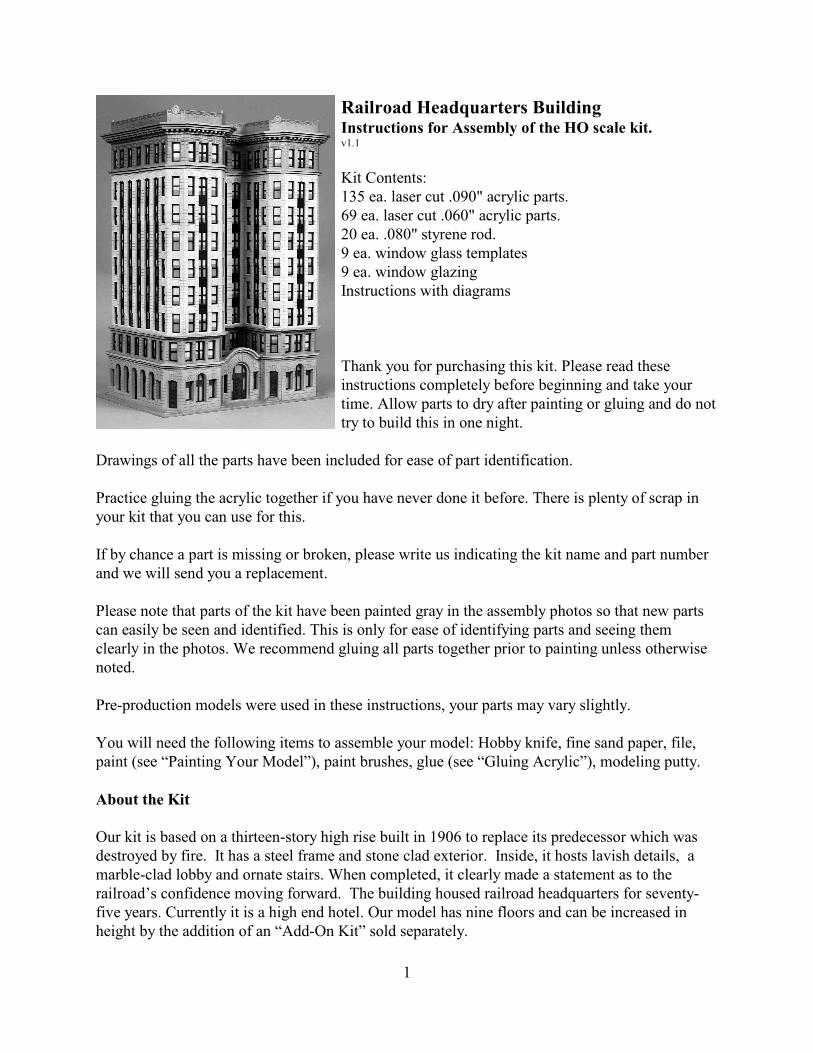
Railroad Headquarters BuildingInstructions for Assembly of the HO scale kit.v1.1
Kit Contents:135 ea. laser cut .090" acrylic parts. 69 ea. laser cut .060" acrylic parts. 20 ea. .080" styrene rod.9 ea. window glass templates9 ea. window glazingInstructions with diagrams
Thank you for purchasing this kit. Please read theseinstructions completely before beginning and take yourtime. Allow parts to dry after painting or gluing and do nottry to build this in one night.
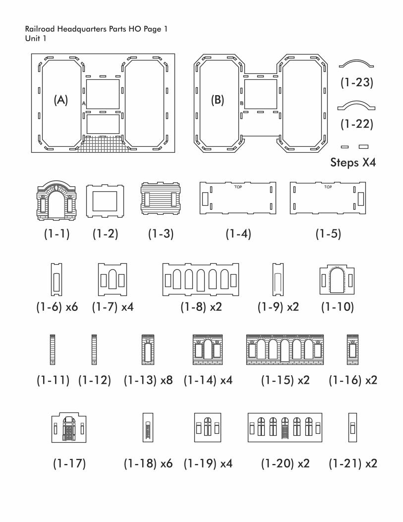
Drawings of all the parts have been included for ease of part identification.
Practice gluing the acrylic together if you have never done it before. There is plenty of scrap inyour kit that you can use for this.
If by chance a part is missing or broken, please write us indicating the kit name and part numberand we will send you a replacement.
Please note that parts of the kit have been painted gray in the assembly photos so that new partscan easily be seen and identified. This is only for ease of identifying parts and seeing themclearly in the photos. We recommend gluing all parts together prior to painting unless otherwisenoted.
Pre-production models were used in these instructions, your parts may vary slightly.
You will need the following items to assemble your model: Hobby knife, fine sand paper, file,paint (see “Painting Your Model”), paint brushes, glue (see “Gluing Acrylic”), modeling putty.
About the Kit
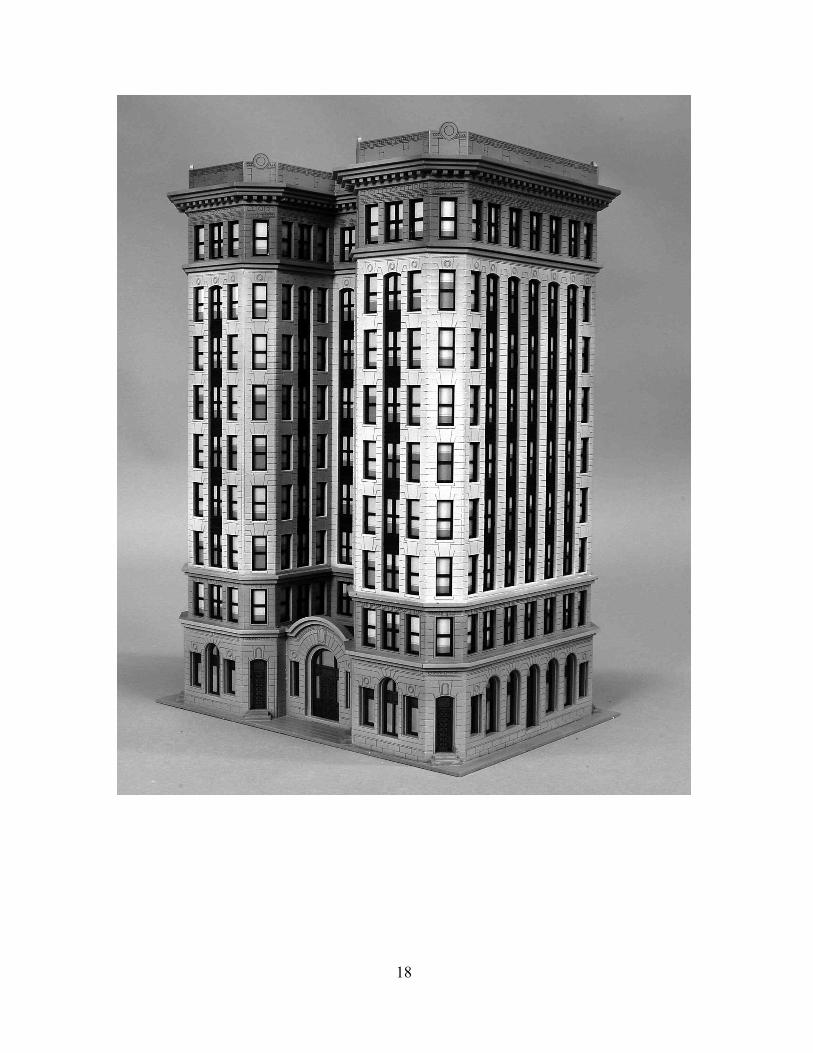
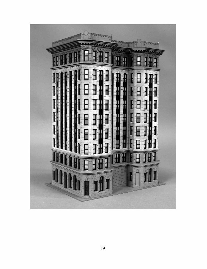
Our kit is based on a thirteen-story high rise built in 1906 to replace its predecessor which wasdestroyed by fire. It has a steel frame and stone clad exterior. Inside, it hosts lavish details, amarble-clad lobby and ornate stairs. When completed, it clearly made a statement as to therailroad’s confidence moving forward. The building housed railroad headquarters for seventy-five years. Currently it is a high end hotel. Our model has nine floors and can be increased inheight by the addition of an “Add-On Kit” sold separately.

2
Gluing Acrylic
Always glue acrylic in a well-ventilated area, and read the glue manufacturer’s label forinstructions.
We recommend using Scalecoat brand “Probond”, “Tenax-7R”, Plastruct brand “BondeneSolvent Cement” or “Plastic Weld Cement”. Most hobby shops carry these products. Or theymay be ordered directly from the manufacturer.
Acrylic must be glued together using a solvent that will melt the two edges and literally fusethem together. To do this, place the two pieces to be joined together and run a bead of solventdown the edge. Capillary action will suck the solvent into the joint and after several seconds thepieces will be fused. After only a few minutes the pieces will be strong enough to work with. Thebond will be completely dry within twenty-four hours using the above-mentioned products.Solvent can be dispensed two ways.
Typically the solvent comes in a small bottle with a brush in the lid. The brush allows you todispense a drop or two of solvent at a time.
You may want to use a polyethylene bottle or syringe with a blunt needle dispenser. This allowslarger amounts of solvent to be dispensed quickly and cleanly. Be sure the bottle you are using isapproved for the solvent you are using or you may melt through it. These bottles may bepurchased from CMR.
Super GlueCyanoacrylate (CA) Super Glue
Parts that are not plastic or are painted prior to gluing must be glued together using a non solventbased glue. This means the parts are held together by the glue and not the process of fusing orwelding them together with solvent. For this we recommend using CA where noted in theinstructions.
Craft Glue
Some parts are easier to glue using craft glue such as “Sobo”. We use craft glue to stickpreviously painted parts together when we want a little working time.
3
Preparing Your Model for Painting
We recommend lightly sanding all parts to remove the raised edge created during the lasercutting process. In order to hide the seams we recommend using “hobbyist putty” such as GreenSquadron modeling putty. Do this in a very well-ventilated area. Apply the putty over the seamsand allow to dry overnight. Once the putty has dried, place a sheet of fine sandpaper on a flatsurface and sand smooth. You may need to apply a second coat of putty and sand again.
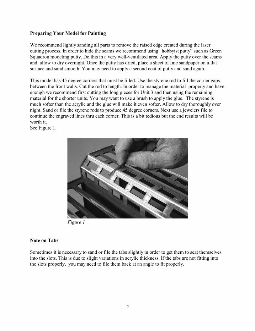
This model has 45 degree corners that must be filled. Use the styrene rod to fill the corner gapsbetween the front walls. Cut the rod to length. In order to manage the material properly and haveenough we recommend first cutting the long pieces for Unit 3 and then using the remainingmaterial for the shorter units. You may want to use a brush to apply the glue. The styrene ismuch softer than the acrylic and the glue will make it even softer. Allow to dry thoroughly overnight. Sand or file the styrene rods to produce 45 degree corners. Next use a jewelers file tocontinue the engraved lines thru each corner. This is a bit tedious but the end results will beworth it. See Figure 1.
Note on Tabs
Sometimes it is necessary to sand or file the tabs slightly in order to get them to seat themselvesinto the slots. This is due to slight variations in acrylic thickness. If the tabs are not fitting intothe slots properly, you may need to file them back at an angle to fit properly.
Figure 1
4
Painting Your Model
After building each unit we primed our building with Krylon Gray spray paint. We also primedthe window frames. For our building paint scheme, we used acrylic hobby paints which areavailable in hobby stores.
We painted the building with two different stone colors. The lower and upper units were paintedwith a sandstone color. The shaft (unit 3) was painted very light gray. The building was thenlightly airbrushed with dirt and grime to give it an aged look. The roof was painted black. Finally we clear coated the building with matte spray to protect the paint finish.
The first floor windows and doors were painted a dark bronze. The upper story windows werepainted black.
Window Glass
There are printed window shades included with your kit. These are designed to be laminated withacetate window glazing prior to installing in your model. The printed window shades arenumbered to correspond with the window frame parts.
Lightly spray glue the window shade pages on the printed side with spray mount and apply asheet of acetate to them. Press in place. We used 3M Spray Mount part number 6065 which isavailable at craft and office supply stores. After painting the window frames glue them to theacetate using super glue (CA).
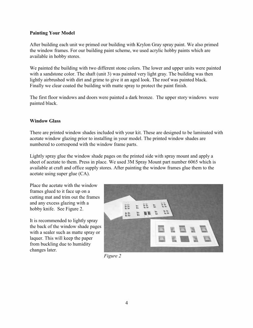
Place the acetate with the windowframes glued to it face up on acutting mat and trim out the framesand any excess glazing with ahobby knife. See Figure 2.
It is recommended to lightly spraythe back of the window shade pageswith a sealer such as matte spray orlaquer. This will keep the paperfrom buckling due to humiditychanges later.
Figure 2
5
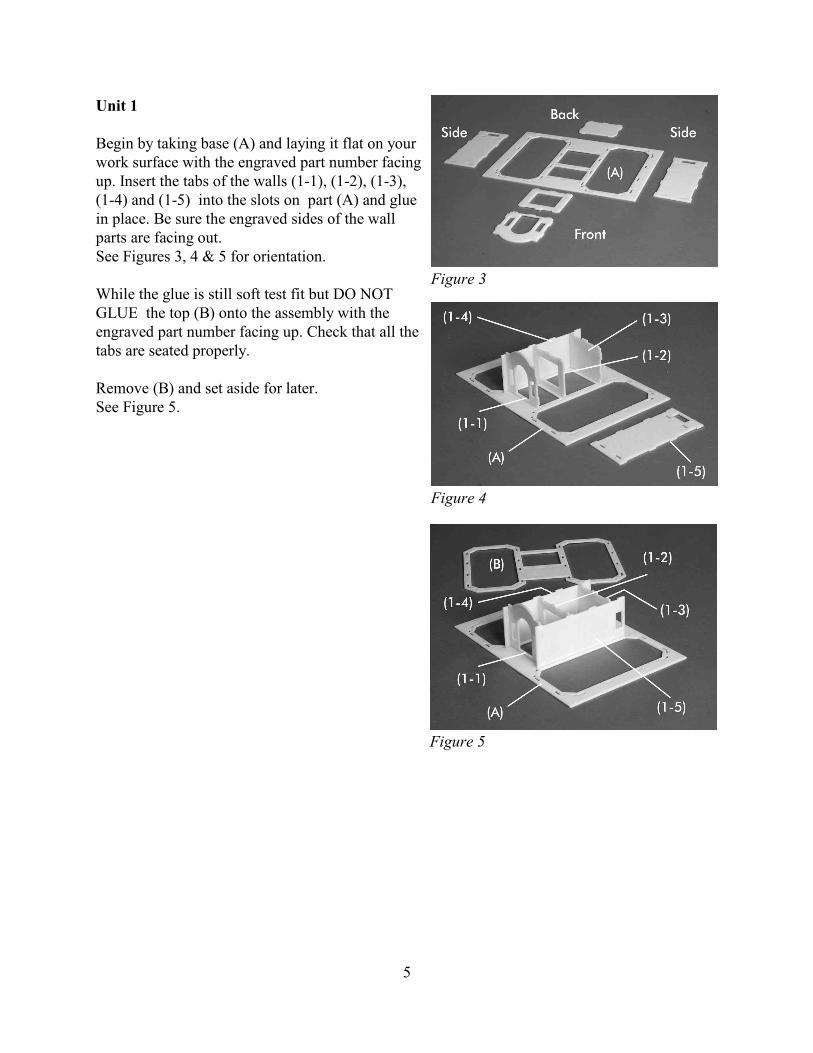
Unit 1
Begin by taking base (A) and laying it flat on yourwork surface with the engraved part number facingup. Insert the tabs of the walls (1-1), (1-2), (1-3),(1-4) and (1-5) into the slots on part (A) and gluein place. Be sure the engraved sides of the wallparts are facing out.See Figures 3, 4 & 5 for orientation.
While the glue is still soft test fit but DO NOTGLUE the top (B) onto the assembly with theengraved part number facing up. Check that all thetabs are seated properly.
Remove (B) and set aside for later.See Figure 5.
Figure 3
Figure 4
Figure 5
6
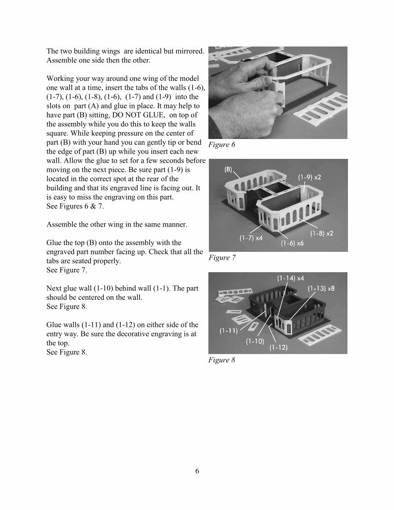
The two building wings are identical but mirrored.Assemble one side then the other.
Working your way around one wing of the modelone wall at a time, insert the tabs of the walls (1-6),(1-7), (1-6), (1-8), (1-6), (1-7) and (1-9) into theslots on part (A) and glue in place. It may help tohave part (B) sitting, DO NOT GLUE, on top ofthe assembly while you do this to keep the wallssquare. While keeping pressure on the center ofpart (B) with your hand you can gently tip or bendthe edge of part (B) up while you insert each newwall. Allow the glue to set for a few seconds beforemoving on the next piece. Be sure part (1-9) islocated in the correct spot at the rear of thebuilding and that its engraved line is facing out. Itis easy to miss the engraving on this part.See Figures 6 & 7.
Assemble the other wing in the same manner.
Glue the top (B) onto the assembly with theengraved part number facing up. Check that all thetabs are seated properly. See Figure 7.
Next glue wall (1-10) behind wall (1-1). The partshould be centered on the wall. See Figure 8.
Glue walls (1-11) and (1-12) on either side of theentry way. Be sure the decorative engraving is atthe top. See Figure 8.
Figure 7
Figure 8
Figure 6

7
Working your way around one wing of the model one wall at a time, glue the walls (1-13), (1-14), (1-13), (1-15), (1-13), (1-14), (1-13) and (1-16) to the assembly. Be sure each wall isperfectly centered on the wall below it using the window openings as guides. The windowopening in the front wall is just slightly larger than the wall behind it and a slight step backshould be visible. Part (1-16) should be flush at the back corner where it meets part (1-3). See Figures 9 & 10
Glue the cornice arch (1-22) over the entryway. It should be flush on the top and tuck into theslots on part (B).See Figure 9.
Glue the small cornice arch part (1-23) to the faceof part (1-22), they should be flush on the top. Youmay want to fill any seams with modelers putty,allow to dry and sand smooth.See Figure 11.
Glue two steps in front of each of the six side doorways as shown.See Figure 11.
You may want to build the rest of the building units before proceeding with the next step. Wehave included the next step here so as to keep the progress in order and show the completion ofone unit before moving on to the next.
See “Preparing Your Model for Painting” for moredetailed information.
Use the .080 styrene rod to fill the corner gapsbetween the walls. Allow to dry thoroughly overnight. Sand or file the styrene rods to produce 45degree corners. Next use a jewelers file to continuethe engraved lines thru each corner.See Figures 1 & 12.
Figure 9 Figure 10
Figure 11
Figure 12
8
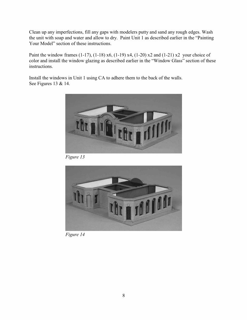
Clean up any imperfections, fill any gaps with modelers putty and sand any rough edges. Washthe unit with soap and water and allow to dry. Paint Unit 1 as described earlier in the “PaintingYour Model” section of these instructions.
Paint the window frames (1-17), (1-18) x6, (1-19) x4, (1-20) x2 and (1-21) x2 your choice ofcolor and install the window glazing as described earlier in the “Window Glass” section of theseinstructions.
Install the windows in Unit 1 using CA to adhere them to the back of the walls.See Figures 13 & 14.
Figure 13
Figure 14

9
Unit 2
Take part (C) and lay it flat on your work surfacewith the engraved part number facing up. Insert thetabs of the walls (2-1) x2, (2-2) and (2-3) into theslots on part (C) and glue in place. Be sure theengraved sides of the wall parts are facing out andthat the decorative strip is at the top of each part,See Figures 15.
While the glue is still soft test fit but DO NOTGLUE the top (D) onto the assembly with theengraved part number facing up. Check that all thetabs are seated properly. Remove (D) and set asidefor later.
Working your way around one wing of the modelone wall at a time insert the tabs of the walls (2-4),(2-5), (2-4), (2-6), (2-4), (2-5) and (2-4) into theslots on part (C) and glue in place.See Figure 16.
Assemble the other wing in the same manner.See Figure 16.
Glue the top (D) onto the assembly with theengraved part number facing up. Check that all thetabs are seated properly.
Use the .080 styrene rod to fill the corner gapsbetween the walls. Allow to dry thoroughly overnight. Sand or file the styrene rods to produce 45degree corners. Next use a jewelers file to continuethe engraved lines thru each corner.See Figure 17.
Figure 15
Figure 16
Figure 17
10
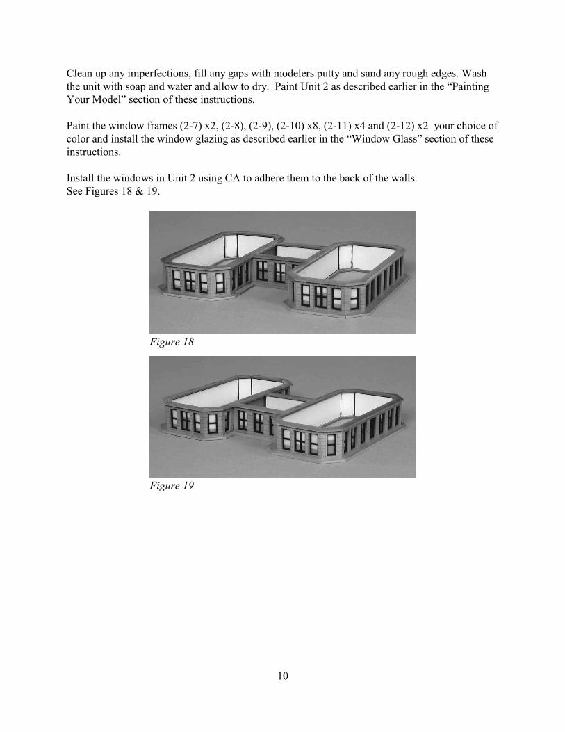
Clean up any imperfections, fill any gaps with modelers putty and sand any rough edges. Washthe unit with soap and water and allow to dry. Paint Unit 2 as described earlier in the “PaintingYour Model” section of these instructions.
Paint the window frames (2-7) x2, (2-8), (2-9), (2-10) x8, (2-11) x4 and (2-12) x2 your choice ofcolor and install the window glazing as described earlier in the “Window Glass” section of theseinstructions.
Install the windows in Unit 2 using CA to adhere them to the back of the walls.See Figures 18 & 19.
Figure 18
Figure 19
11
Unit 3
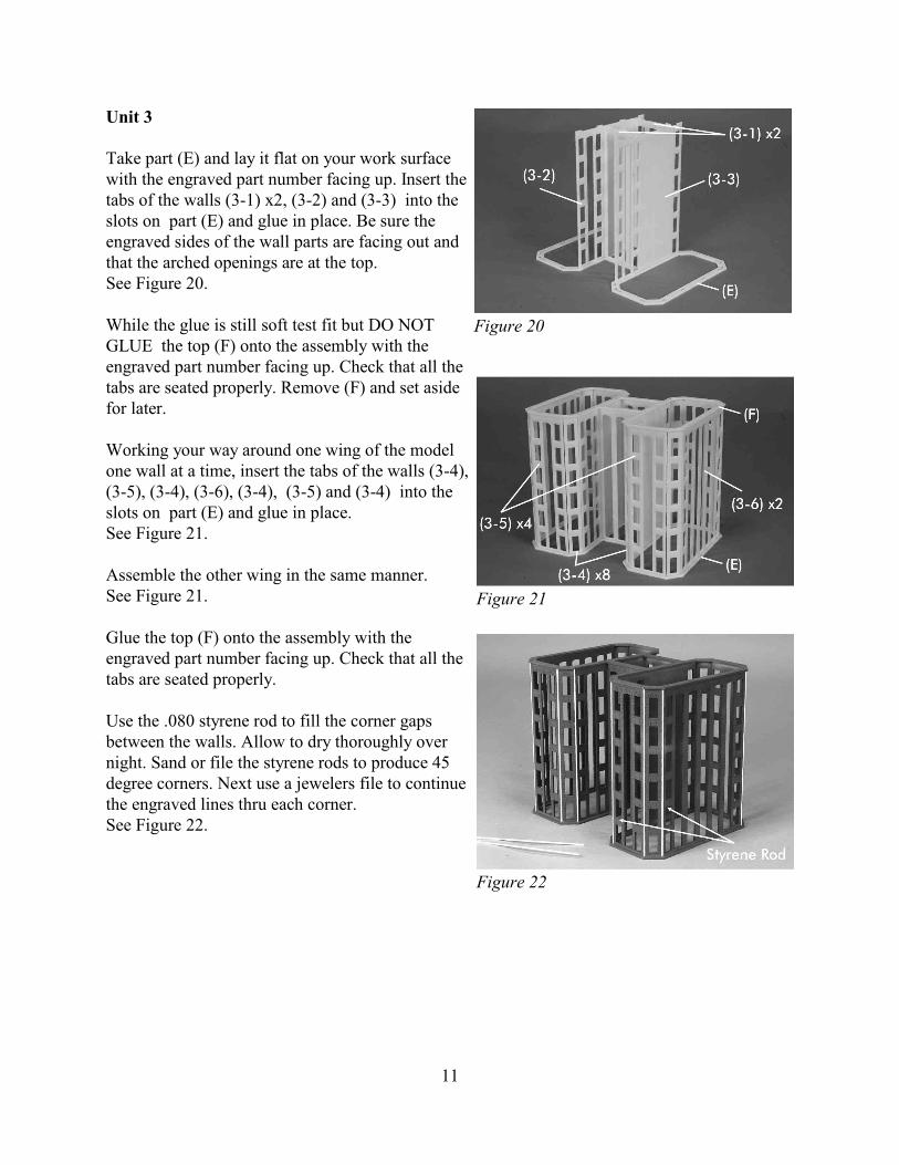
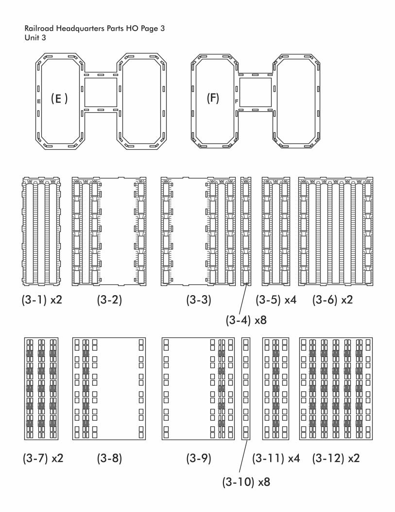
Take part (E) and lay it flat on your work surfacewith the engraved part number facing up. Insert thetabs of the walls (3-1) x2, (3-2) and (3-3) into theslots on part (E) and glue in place. Be sure theengraved sides of the wall parts are facing out andthat the arched openings are at the top.See Figure 20.
While the glue is still soft test fit but DO NOTGLUE the top (F) onto the assembly with theengraved part number facing up. Check that all thetabs are seated properly. Remove (F) and set asidefor later.
Working your way around one wing of the modelone wall at a time, insert the tabs of the walls (3-4),(3-5), (3-4), (3-6), (3-4), (3-5) and (3-4) into theslots on part (E) and glue in place.See Figure 21.
Assemble the other wing in the same manner.See Figure 21.
Glue the top (F) onto the assembly with theengraved part number facing up. Check that all thetabs are seated properly.
Use the .080 styrene rod to fill the corner gapsbetween the walls. Allow to dry thoroughly overnight. Sand or file the styrene rods to produce 45degree corners. Next use a jewelers file to continuethe engraved lines thru each corner.See Figure 22.
Figure 20
Figure 21
Figure 22
12
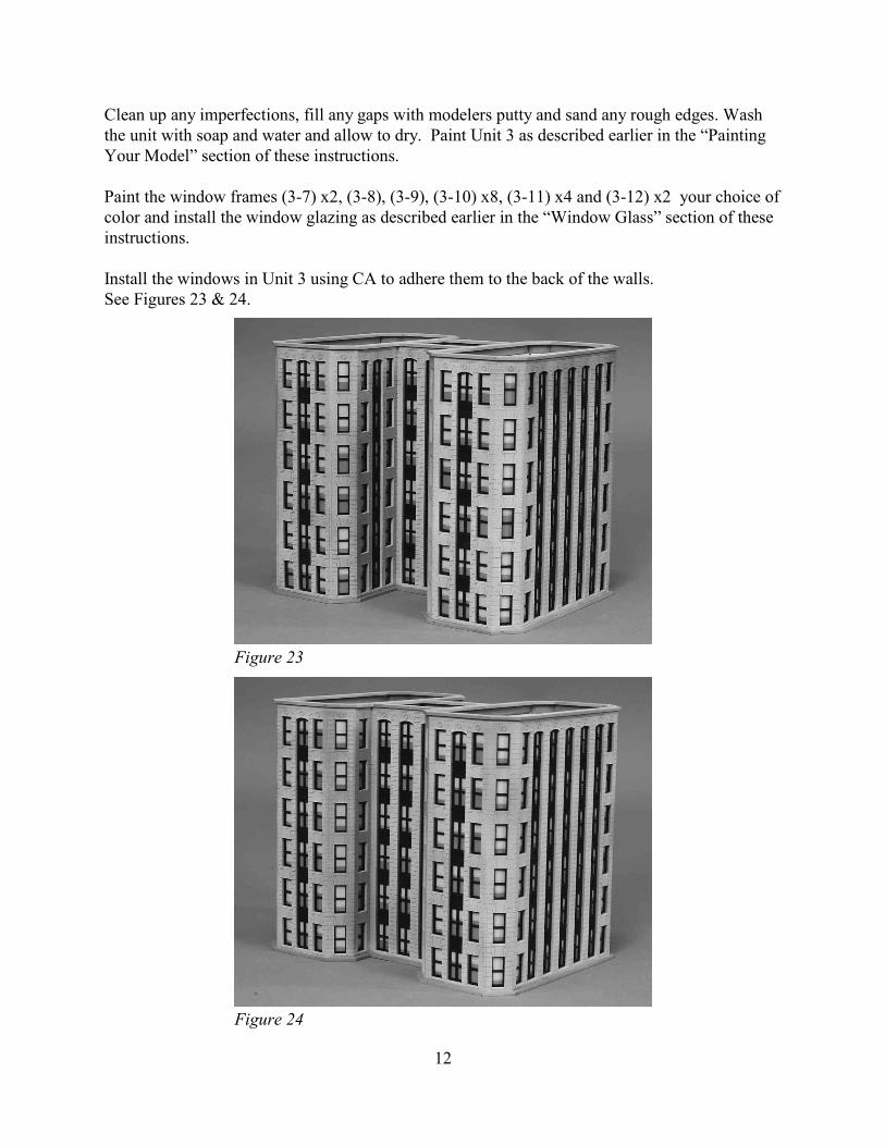
Clean up any imperfections, fill any gaps with modelers putty and sand any rough edges. Washthe unit with soap and water and allow to dry. Paint Unit 3 as described earlier in the “PaintingYour Model” section of these instructions.
Paint the window frames (3-7) x2, (3-8), (3-9), (3-10) x8, (3-11) x4 and (3-12) x2 your choice ofcolor and install the window glazing as described earlier in the “Window Glass” section of theseinstructions.
Install the windows in Unit 3 using CA to adhere them to the back of the walls.See Figures 23 & 24.
Figure 23
Figure 24
13
Unit 4
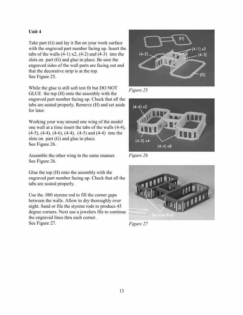
Take part (G) and lay it flat on your work surfacewith the engraved part number facing up. Insert thetabs of the walls (4-1) x2, (4-2) and (4-3) into theslots on part (G) and glue in place. Be sure theengraved sides of the wall parts are facing out andthat the decorative strip is at the top.See Figure 25.
While the glue is still soft test fit but DO NOTGLUE the top (H) onto the assembly with theengraved part number facing up. Check that all thetabs are seated properly. Remove (H) and set asidefor later.
Working your way around one wing of the modelone wall at a time insert the tabs of the walls (4-4),(4-5), (4-4), (4-6), (4-4), (4-5) and (4-4) into theslots on part (G) and glue in place.See Figure 26.
Assemble the other wing in the same manner.See Figure 26.
Glue the top (H) onto the assembly with theengraved part number facing up. Check that all thetabs are seated properly.
Use the .080 styrene rod to fill the corner gapsbetween the walls. Allow to dry thoroughly overnight. Sand or file the styrene rods to produce 45degree corners. Next use a jewelers file to continuethe engraved lines thru each corner.See Figure 27.
Figure 25
Figure 26
Figure 27
14
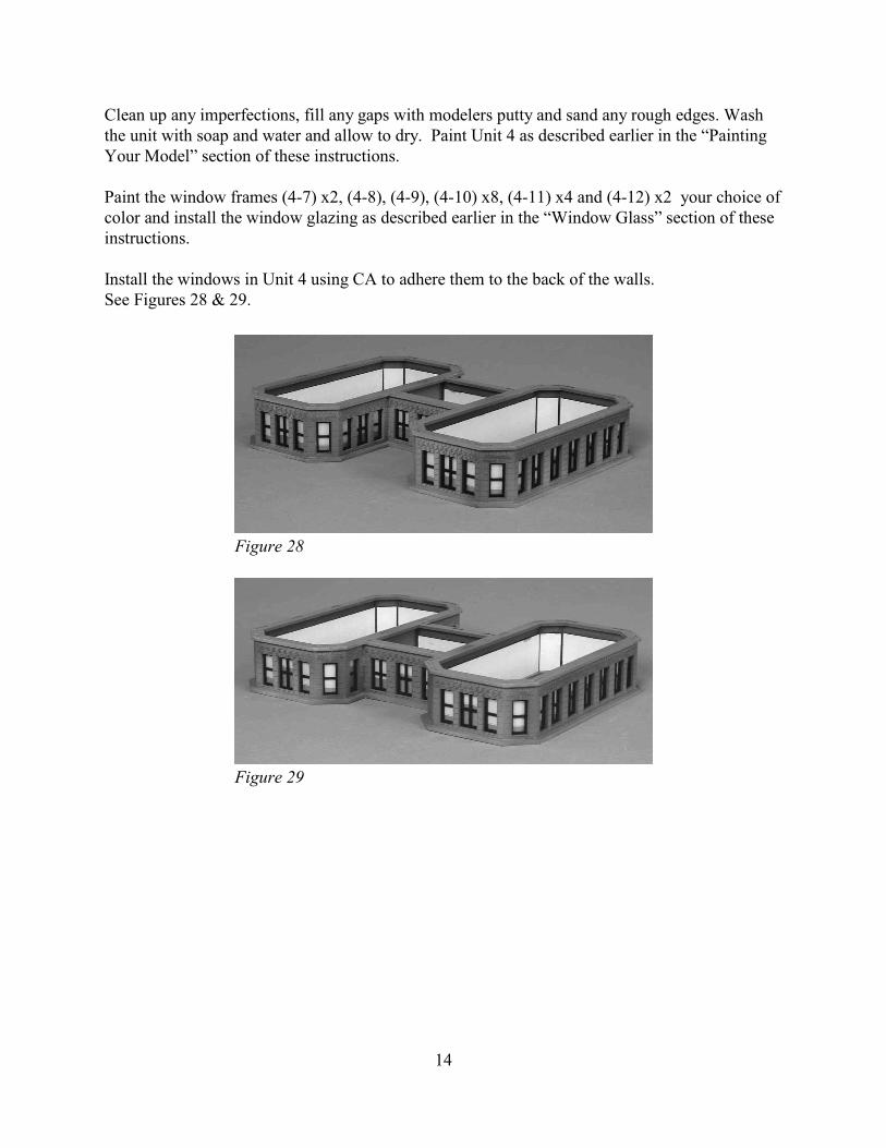
Clean up any imperfections, fill any gaps with modelers putty and sand any rough edges. Washthe unit with soap and water and allow to dry. Paint Unit 4 as described earlier in the “PaintingYour Model” section of these instructions.
Paint the window frames (4-7) x2, (4-8), (4-9), (4-10) x8, (4-11) x4 and (4-12) x2 your choice ofcolor and install the window glazing as described earlier in the “Window Glass” section of theseinstructions.
Install the windows in Unit 4 using CA to adhere them to the back of the walls.See Figures 28 & 29.
Figure 28
Figure 29

15
Unit 5
To build the roof, place part (L) with the numberfacing up on your work surface. Glue part (K) to itwith the engraved number facing down. Make surethe parts are perfectly centered. Next glue part (J)to part (K) with the engraved number facing down.Use the center holes in the parts for alignment.Finally glue Part (I) to (J) with the engravednumber facing down.See Figure 30.
To build the parapet wall around the roof begin inthe center. Make sure the engraved side of eachpart is always facing out. Insert the tabs of wall(5-1) in the center slots at the front of the building.Next glue walls (5-2) and (5-3) into the slots oneither side of part (5-1). The parts should overlapthe ends of part (5-1) and form a nice squarecorner.
Do the same at the back of the building with part(5-1) in the center sandwiched between parts (5-4)and (5-5).See Figure 31.
Working your way around one wing of the modelone wall at a time insert the tabs of the walls (5-6),(5-7), (5-6), (5-8), (5-6), (5-7) and (5-6) into theslots on part (L) and glue in place.See Figure 32.
Assemble the other wing in the same manner.See Figure 32.
Figure 30
Figure 31
Figure 32

16
Use the .080 styrene rod to fill the corner gapsbetween the walls. Allow to dry thoroughly overnight. Sand or file the styrene rods to produce 45degree corners. Next use a jewelers file to continuethe engraved lines thru each corner.See Figure 33.
Clean up any imperfections, fill any gaps withmodelers putty and sand any rough edges. Glue theroof hatch (5-9) to the top of the roof. If youaccidentally placed part (L) upside down and the engraved letter is showing you can cover it withthe roof hatch. Wash the unit with soap and water and allow to dry. Paint Unit 5 as describedearlier in the “Painting Your Model” section of these instructions.See Figure 34.
Figure 33
Figure 34

17
Final Assembly
Now that you have built all of the building units, it is time to assemble them. Make sure that thebottom and top of each unit is perfectly flat and smooth. Sand or file any imperfections off asnecessary.
Glue the units together one at a time and allow to dry before proceeding to the next unit. You canrun a bead of glue along the cornice where the two pieces meet. The interior rectangular openingsshould align from one unit to the next. Continue gluing the units together in this fashion makingsure that everything is straight and true as you go along.
Once completed touch up any glue and paint imperfections along the cornices.
Your building is finished and ready to install on your layout. You may add roof details, awnings,lights and other details. We thank you for purchasing this kit from CMR and hope that you haveenjoyed building it. Be sure to see our other kits at www.cmrtrain.com.
18
19
BA
Railroad HeadquartersUnit 1
Parts HO Page 1
(1-1)
(A) (B)
(1-2) (1-3) (1-4) (1-5)
(1-6) x6 (1-7) x4 (1-8) x2 (1-9) x2 (1-10)
(1-16) x2
(1-17) (1-18) x6 (1-19) x4 (1-20) x2 (1-21) x2
(1-22)
Steps X4
(1-23)
(1-13) x8 (1-14) x4 (1-15) x2(1-11) (1-12)
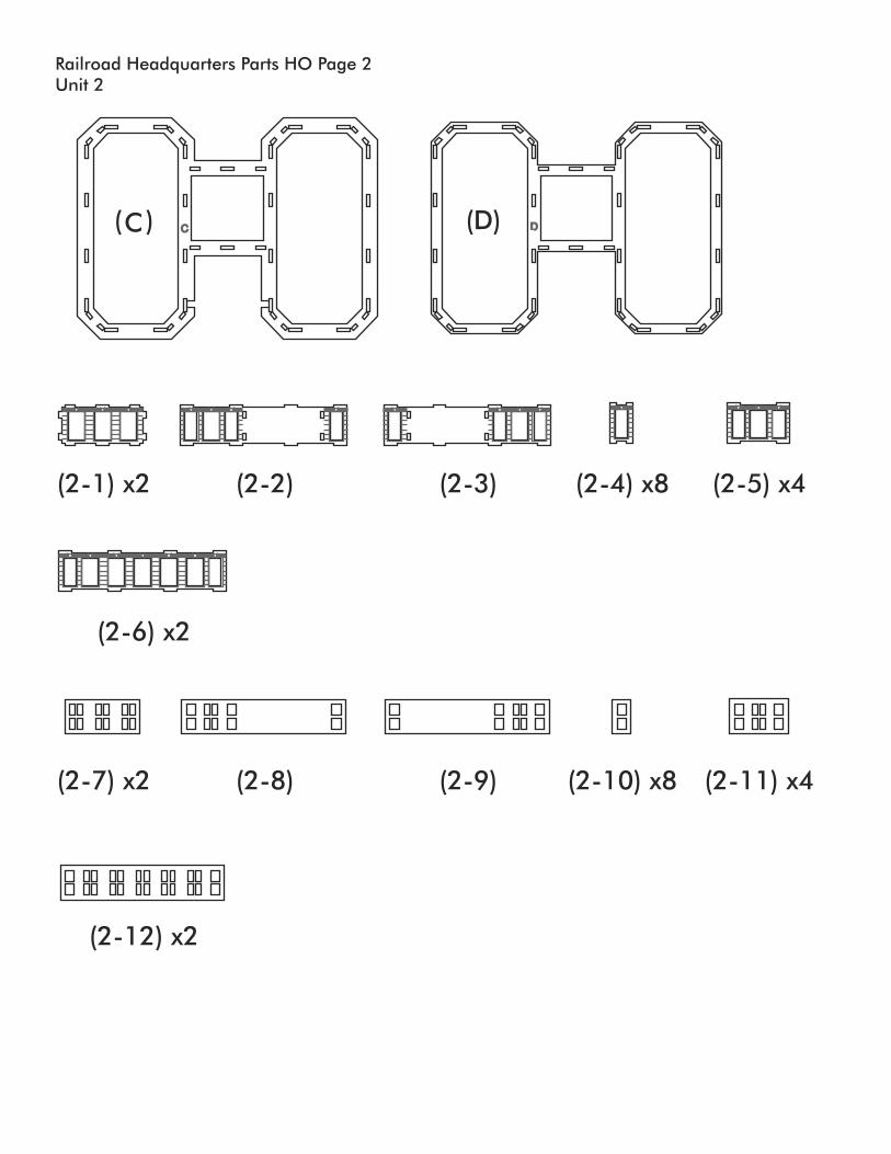
Railroad HeadquartersUnit 2
Parts HO Page 2
DC (D)( )C
(2-1) x2
(2-7) x2
(2-2)
(2-8)
(2-3)
(2-9)
(2-6) x2
(2-12) x2
(2-5) x4
(2-11) x4
(2-4) x8
(2-10) x8
FE
Railroad HeadquartersUnit 3
Parts HO Page 3
(F)( )E
(3-1) x2 (3-6) x2
(3-7) x2 (3-8) (3-9)
(3-10) x8
(3-11) x4 (3-12) x2
(3-2) (3-3) (3-5) x4
(3-4) x8

G H
Railroad HeadquartersUnit 4
Parts HO Page 4
(H)(G)
(4-1) x2
(4-7) x2
(4-2)
(4-8)
(4-3)
(4-9)
(4-6) x2
(4-12) x2
(4-5) x4
(4-11) x4
(4-4) x8
(4-10) x8
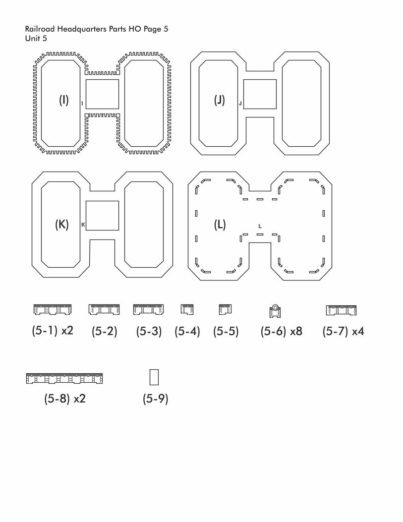
Railroad HeadquartersUnit 5
Parts HO Page 5
(J)
(L)
(I)
(K)
I J
K L
(5-1) x2 (5-2) (5-3) (5-4) (5-5)
(5-8) x2 (5-9)
(5-7) x4(5-6) x8