Embed Size (px)
Citation preview

RAIL THROUGH-
PLATE GIRDER 3-D
ANALYSIS FOR
FUNDAMENTAL
EVALUATION OF
KNEE BRACE
BEHAVIOR
STEPHEN DICK
PE PHD
DUNCAN PATERSON
PE PHD
ANNA M. RAKOCZY
PHD
BIOGRAPHY
Stephen Dick has 36 years of
experience in railroad design,
construction, and special studies
with emphasis in bridge and
structural design. His expertise
is in the area of railroad
loadings and their effects on
fatigue life and overall
capacity. He is a Principal
Investigator with the
Transportation Technology
Center, Inc. in Pueblo, Colorado
and is an adjunct professor at
Colorado State University -
Pueblo.
Duncan Paterson is the Bridge
Section Manager for HDR’s
Cincinnati office. He is a
graduate of Michigan State
University with an MS and PhD
from Lehigh University. Dr.
Paterson is currently a member
of AREMA Committee 15 –
Steel Structures, a member of
the TRB Standing Committee
on Fabrication and Inspection of
Metal Structures, and Co-chairs
the AASHTO/NSBA Steel
Bridge Collaboration Task
Group for Orthotropic Decks.
Anna M. Rakoczy is a Senior
Engineer II at Transportation
Technology Center, Inc. She
earned her Ph. D. degree in
Civil Engineering from the
University of Nebraska -
Lincoln, and her B.S. and M.S.
degrees from the University of
Technology and Live Science in
Poland. Dr. Rakoczy is
currently a member of the TRB
Standing Committee on Steel
Bridges, a member of AREMA
and ASCE.
SUMMARY
Through-plate girders (TPGs)
are a common structural choice
for medium span railroad
bridges, in particular where
clearance below the structure
needs to be maximized. Integral
to TPG behavior is the knee
brace connection from the
girder web and top flange to the
floorbeam or floor system. The
Knee Brace acts as a multi-
function structural element. It
restrains the top compression
flange from lateral displacement
as a bracing device and it is a
load transfer mechanism
between the floorbeams and the
TPG. Design manuals provide
limited guidance on loads to
proportion knee braces that have
led to overly conservative
designs and severely poor
ratings that did not accurately
reflect the behavior of the
structures. In order to better
understand the knee brace
behavior and their effect on the
structure, two full-scale 3-
dimensional finite element
models were developed to
evaluate the actual behavior of
TPGs subjected to Cooper E-80
design loads. Concurrently,
instrumentation was applied to
an existing TPG which
corroborated the results of the
finite element studies. The
results have led to a more
refined understanding of knee
brace behavior.
1
RAIL THROUGH-PLATE GIRDER 3-D ANALYSIS FOR
FUNDAMENTAL EVALUATION OF KNEE BRACE
BEHAVIOR
Duncan Paterson PE PhD, HDR Inc. (Corresponding Author)
Anna Rakoczy PhD, AAR Transportation Technology Center, Inc.
Stephen Dick, PE PhD, AAR Transportation Technology Center, Inc.
ABSTRACT
Through-plate girders (TPGs) are a common
structural choice for medium span railroad
bridges, in particular where clearance below the
structure needs to be maximized. Integral to TPG
behavior is the knee brace connection from the
girder web and top flange to the floorbeam or floor
system. The Knee Brace is defined by the
American Railway Engineering and Maintenance-
of-way Association (AREMA) (1) as a “stiffened
diagonal plate connecting the top of a floorbeam to
a girder or truss vertical” and it acts as a multi-
function structural element. First, it restrains the
top compression flange from lateral displacement
as a bracing device. Second, it is a load transfer
mechanism between the floorbeams and the TPG.
The American Association of State Highway and
Transportation Officials (AASHTO) (2) indicates
that knee braces need to be designed in the same
manner as gusset plates, but does not provide
guidance on loads. AREMA provides limited
guidance on loads to proportion knee braces, but
leaves room for interpretation on their application.
During a review of designs and ratings, AREMA
Committee 15 for Steel Structures discovered that
engineers were misinterpreting current
recommendations for knee brace evaluation, likely
as a result of the lack of available guidance. This
led to overly conservative designs and severely
poor ratings that did not accurately reflect the
behavior of the structures. In order to better
understand the knee brace behavior and their
effect on the structure, two full-scale 3-
dimensional finite element models were developed
to evaluate the actual behavior of TPGs subjected
to Cooper E-80 design loads. Concurrently,
instrumentation was applied to an existing TPG
which corroborated the results of the finite
element studies. The results have led to a more
refined understanding of knee brace behavior and
are the subject of proposed ballot language for the
AREMA Manual for Railway Engineering (2017
ed.). The results of the finite element study, the
field instrumentation results, and the proposed
change to the AREMA Manual are presented.
BACKGROUND
Specification Guidance Through-plate girders (TPGs) are a common
structural choice for medium span railroad
bridges, in particular where clearance below the
structure needs to be maximized. And although
less common, TPGs can also be found on highway
systems. Integral to TPG behavior is the knee
brace connection from the girder web and top
flange to the floorbeam or floor system. The
American Railway Engineering and Maintenance-
of-way Association Chapter 15 (AREMA) (1)
defines a knee brace as a “stiffened diagonal plate
connecting the top of a floorbeam to a girder or
truss vertical.” The knee braces primarily acts as a
stiffening strut that restrains the top compression
flange from lateral displacement.
For the design of knee braces, AREMA Chapter
15 has guidance in two sections. Article 15-1.11.1
states:
“The top flanges of through plate
girders shall be braced at the panel
points by brackets with web plates (knee
braces). The brackets shall extend to the
top flange of the main girder and be as
wide as clearance will allow. They shall
be attached securely to a stiffener on the
girders and to the top flange of the
floorbeam. On solid floor bridges the
brackets shall not be more than 12 feet

2
apart. The brackets shall be designed for
the bracing force specified in Article
1.3.11.”
Article 1.3.11 states:
“The lateral bracing of the compression
chords or flanges of trusses, deck girders
and through girders and between the
posts of viaduct towers shall be
proportioned for a transverse shear
force in any panel equal to 2.5% of the
total axial force in both members in that
panel, in addition to the shear force from
the specified lateral loads.”
There is currently no associated commentary
language for these articles. The implication by
these two articles is that bracing of the TPG flange
should be proportioned to carry a notional load
that is 2.5% of the axial load in the compression
flange. For example, if the compression flange
stress is 19 ksi for a 3” x 24” flange, the required
notional load would be:
2.5%�19� ∙ 3 ∙ 24 � = 34.2��
This notional load would then be applied at the
compression flange elevation, perpendicular to the
flange, to be resisted by the knee brace (Figure 1).
Figure 1. TPG section showing knee brace
notional load
The American Association of State Highway and
Transportation Officials (AASHTO) (2) does not
provide nearly as specific guidance on knee
braces, indicating that knee braces need to be
designed in the same manner as gusset plates, but
does not provide guidance on loads. Article 6.14.1
states:
“6.14.1—Through-Girder Spans
Where beams or girders comprise the
main members of through-spans, such
members shall be stiffened against
lateral deformation by means of gusset
plates or knee braces with solid webs
connected to the stiffeners on the main
members and the floorbeams.”
This information is not particularly useful to the
designer, other than the acknowledgement that the
knee brace must be designed for the appropriate
loads.
Additional References Chapter 12 of the Guide to Stability Design
Criteria for Metal Structures by Galambos (3) is
on bracing systems for compression members, and
contains additional guidance for designers. The
chapter states that the bracing force (Fbr) for
strength design is related to the applied moment
(M), the depth (h) of the girder and a factor
relative to single curvature or reverse curvature of
the girder (Cd):
��� =0.01 ∙ � ∙ ��
ℎ
Eq. 1
It can be seen that this guidance is similar to that
of AREMA, with the flange force (M/h) multiplied
by a factor (0.01·Cd). The chapter also
recommends for discrete bracing of columns, that
a bracing force of 0.01P should be used, which is
equivalent to the flange force at a point using Eq.
1. It should be noted that this chapter references
load and resistance factored design (LRFD)
methodology, while AREMA is based on
allowable stress design (ASD).
AREMA Bracing Notional Load Further understanding of the AREMA notional
load comes from Nattere et al (4). The paper
presents a more direct derivation of bracing based
on an initial out of straightness and adjacent point
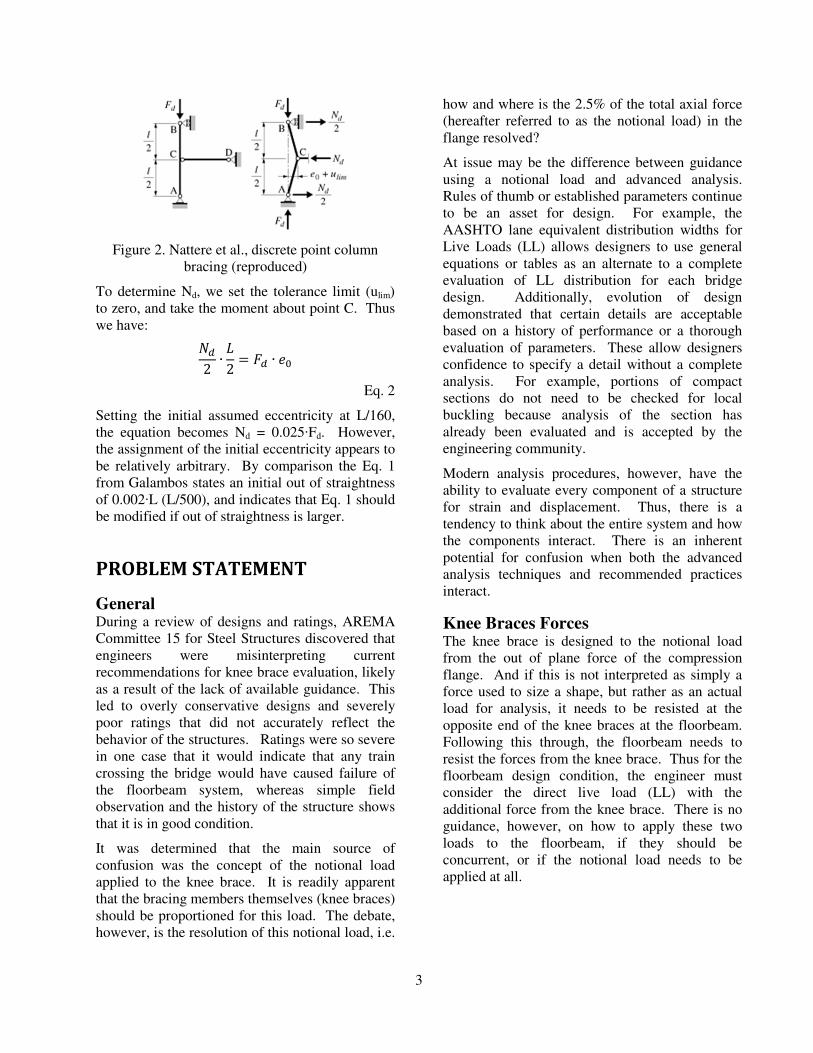
of support (Figure 2).
3
Figure 2. Nattere et al., discrete point column
bracing (reproduced)
To determine Nd, we set the tolerance limit (ulim)
to zero, and take the moment about point C. Thus
we have:
��
2∙�
2= �� ∙ ��
Eq. 2
Setting the initial assumed eccentricity at L/160,
the equation becomes Nd = 0.025·Fd. However,
the assignment of the initial eccentricity appears to
be relatively arbitrary. By comparison the Eq. 1
from Galambos states an initial out of straightness
of 0.002·L (L/500), and indicates that Eq. 1 should
be modified if out of straightness is larger.
PROBLEM STATEMENT
General During a review of designs and ratings, AREMA
Committee 15 for Steel Structures discovered that
engineers were misinterpreting current
recommendations for knee brace evaluation, likely
as a result of the lack of available guidance. This
led to overly conservative designs and severely
poor ratings that did not accurately reflect the
behavior of the structures. Ratings were so severe
in one case that it would indicate that any train
crossing the bridge would have caused failure of
the floorbeam system, whereas simple field
observation and the history of the structure shows
that it is in good condition.
It was determined that the main source of
confusion was the concept of the notional load
applied to the knee brace. It is readily apparent
that the bracing members themselves (knee braces)
should be proportioned for this load. The debate,
however, is the resolution of this notional load, i.e.
how and where is the 2.5% of the total axial force
(hereafter referred to as the notional load) in the
flange resolved?
At issue may be the difference between guidance
using a notional load and advanced analysis.
Rules of thumb or established parameters continue
to be an asset for design. For example, the
AASHTO lane equivalent distribution widths for
Live Loads (LL) allows designers to use general
equations or tables as an alternate to a complete
evaluation of LL distribution for each bridge
design. Additionally, evolution of design
demonstrated that certain details are acceptable
based on a history of performance or a thorough
evaluation of parameters. These allow designers
confidence to specify a detail without a complete
analysis. For example, portions of compact
sections do not need to be checked for local
buckling because analysis of the section has
already been evaluated and is accepted by the
engineering community.
Modern analysis procedures, however, have the
ability to evaluate every component of a structure
for strain and displacement. Thus, there is a
tendency to think about the entire system and how
the components interact. There is an inherent
potential for confusion when both the advanced
analysis techniques and recommended practices
interact.
Knee Braces Forces The knee brace is designed to the notional load
from the out of plane force of the compression
flange. And if this is not interpreted as simply a
force used to size a shape, but rather as an actual
load for analysis, it needs to be resisted at the
opposite end of the knee braces at the floorbeam.
Following this through, the floorbeam needs to
resist the forces from the knee brace. Thus for the
floorbeam design condition, the engineer must
consider the direct live load (LL) with the
additional force from the knee brace. There is no
guidance, however, on how to apply these two
loads to the floorbeam, if they should be
concurrent, or if the notional load needs to be
applied at all.
4
EVALUATION OF KNEE BRACE
AND FLOORBEAMS IN TPG
SYSTEMS
General Concept The live load is eccentric to both of the supporting
TPGs and creates a rotation of the TPG-floorbeam
frame structure. The loads create an inward
rotation (torsion force) with the system deforming
to the shape (exaggerated) show in Figure 3.
Figure 3. TPG Frame-action rotation
The rotation is resisted by both the out of plane
stiffness of the flange plate and the frame
structure. The knee braces contribute to the
stiffness and resistance of the frame. The inward
rotation can create a compression force between
the compression flange and the floorbeam as it
resist the inward rotation. Conversely, as the
floorbeam is loaded by the axles, this can induce
tension between the floorbeam and the
compression flange. The key to evaluating how
the system works is to evaluate how the whole
TPG system acts in three-dimensional (3D) space.
Or in other words, how are knee braces and
floorbeams loaded relative to the position of the
LL along the span.
In order to better understand the knee brace
behavior and their effect on the structure, two full-
scale 3-dimensional finite element models were
developed to evaluate the actual behavior of TPGs
subjected to Cooper E-80 design loads. Both are
modeled as open deck systems (no ballast), the
first using a floorbeam-stringer configuration, the
second using a floorbeam only configuration.
Concurrently, instrumentation was applied to an
existing TPG which corroborated the results of the
finite element studies.
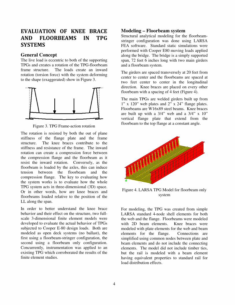
Modeling – Floorbeam system Structural analytical modeling for the floorbeam-
stringer configuration was done using LARSA
FEA software. Standard static simulations were
performed with Cooper E80 moving loads applied
along the bridge. The bridge is a simply supported
span, 72 feet 6 inches long with two main girders
and a floorbeam system.
The girders are spaced transversely at 20 feet from
center to center and the floorbeams are spaced at
two feet center to center in the longitudinal
direction. Knee braces are placed on every other
floorbeam with a spacing of 4 feet (Figure 4).
The main TPGs are welded girders built up from
1” x 120” web plates and 2” x 24” flange plates.
Floorbeams are W16x89 steel beams. Knee braces
are built up with a 3/4” web and a 3/4” x 10”
vertical flange plate that extend from the
floorbeam to the top flange at a constant angle.
Figure 4. LARSA TPG Model for floorbeam only
system
For modeling, the TPG was created from simple
LARSA standard 4-node shell elements for both
the web and the flange. Floorbeams were modeled
with 2D beam elements. Knee braces were
modeled with plate elements for the web and beam
elements for the flange. Connections are
simplified using common nodes between plate and
beam elements and do not include the connecting
elements. The model did not include timber ties,
but the rail is modeled with a beam element
having equivalent properties to standard rail for
load distribution effects.

5
Model – Floorbeam-stringer system Structural analytical modeling for the floorbeam-
stringer configuration was done using LUSAS
FEA software. Standard static simulations were
performed with Cooper E80 moving loads applied
along the bridge. The bridge is a simply supported
span, 64 feet long with two main girders and
system of floorbeams and stringers.
The girders are spaced transversely at 16 feet 1
inch from center to center, the floorbeams are
spaced at 15 feet 8 inches in the longitudinal
direction and the stringers are spaced transversely
with 2 feet 9 inches from exterior stringers to the
interior stringer and 2 feet 2 inches between
internal stringers (Figure 5).
The main girders are built up from 3/8” x 73” web
plates total depth, 3/8” x 14” upper and lower
cover plates, with 6” x 6” x 3/8” angles. Vertical
web stiffeners are spaced at approximately 7 ft.
intervals. The floor-beams are also built up
sections with 3/8”x42-1/4” web plates and 6” 6”
angles: external floor-beams have 6” x 6” x 9/16”
double angles, while internal floorbeams L1 and
L2 have 6” x 6” x 3/4” double angles. At the
connection with the plate girder, knee bracing is
extended to the web plates up to the top of the
girders. The knee brace plates are 3/8” x 32” long
x 30” tall. The stringers are historic rolled S20x75
beams. All connections between members within
the structure are made using rivets with a nominal
diameter of 7/8”. The stringer-to-floorbeam
connection is made using double angles riveted to
stringer and floor-beam webs. All parts of main
girders were created as thin shell elements.
Regular quadrilateral shape (QSI4) of elements
was used to mesh all parts.
Timber ties and the rail were modeled for load
distribution effects. Rail is modeled by a beam
element with equivalent properties to standard rail.
Timber ties are modeled as 10” x 10” x 9’-0”,
spaced 16 in. from center to center. Volume
elements were used to create ties in LUSAS.
Regular hexahedral shape (HX8M) of elements
was used to mesh all parts.
(a)
(b)
Figure 5. LUSAS TPG Model for floorbeam-
stringer system (a) overall model, and (b) framing
plan layout
The overall system mesh is shown in Figure 6.
Figure 6. Finite element mesh for TPG floorbeam-
stringer system
Modeling Results Deflected Shape
For both models, the deflected shape is as
expected. Notably, the TPG deflects as a pinned
6
supported girder and the girder rotates inward
towards the eccentric LL (Figure 7).
(a) (knee braces not shown)
(b)
Figure 7. TPG deflected shapes and torsional
rotation for (a) LARSA Model and (b) LUSAS
Model
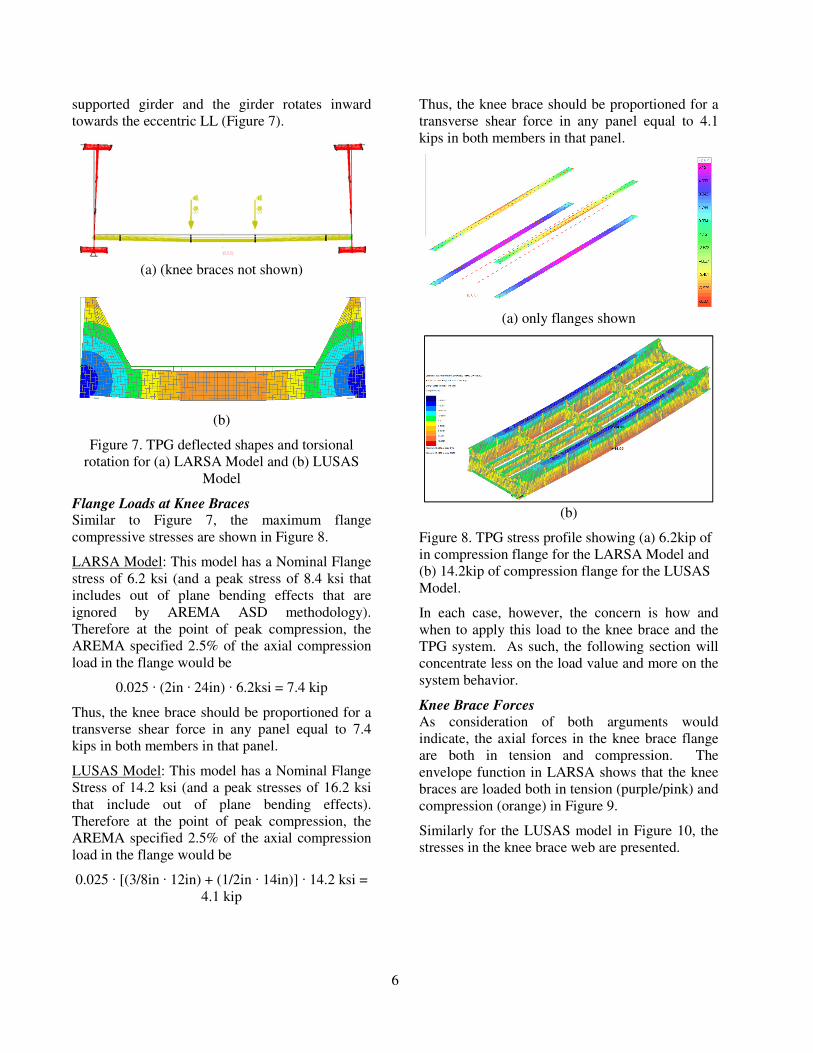
Flange Loads at Knee Braces Similar to Figure 7, the maximum flange
compressive stresses are shown in Figure 8.
LARSA Model: This model has a Nominal Flange
stress of 6.2 ksi (and a peak stress of 8.4 ksi that
includes out of plane bending effects that are
ignored by AREMA ASD methodology).
Therefore at the point of peak compression, the
AREMA specified 2.5% of the axial compression
load in the flange would be
0.025 · (2in · 24in) · 6.2ksi = 7.4 kip
Thus, the knee brace should be proportioned for a
transverse shear force in any panel equal to 7.4
kips in both members in that panel.
LUSAS Model: This model has a Nominal Flange
Stress of 14.2 ksi (and a peak stresses of 16.2 ksi
that include out of plane bending effects).
Therefore at the point of peak compression, the
AREMA specified 2.5% of the axial compression
load in the flange would be
0.025 · [(3/8in · 12in) + (1/2in · 14in)] · 14.2 ksi =
4.1 kip
Thus, the knee brace should be proportioned for a
transverse shear force in any panel equal to 4.1
kips in both members in that panel.
(a) only flanges shown
(b)
Figure 8. TPG stress profile showing (a) 6.2kip of
in compression flange for the LARSA Model and
(b) 14.2kip of compression flange for the LUSAS
Model.
In each case, however, the concern is how and
when to apply this load to the knee brace and the
TPG system. As such, the following section will
concentrate less on the load value and more on the
system behavior.
Knee Brace Forces
As consideration of both arguments would
indicate, the axial forces in the knee brace flange
are both in tension and compression. The
envelope function in LARSA shows that the knee
braces are loaded both in tension (purple/pink) and
compression (orange) in Figure 9.
Similarly for the LUSAS model in Figure 10, the
stresses in the knee brace web are presented.

7
Figure 9. LARSA Knee Brace flange force
showing both tension and compression
Figure 10. LUSAS Knee Brace plate stresses
showing both tension and compression
The knee braces are distributing forces that are
clearly being resisted by the floorbeam, otherwise,
this would be a zero force member. It is therefore
how those loads affect the floorbeam that is
investigated. That is, does the load being resolved
impart an increase (or decrease) in moment on the
floorbeam, or does it act as a separate system away
from the loaded floorbeam? Also, of note is that
the largest knee-brace axial force shown is
representative of the resolved forces for a
transverse load of approximately 1.75% of the
applied axial compression flange force as
predicted by the model (within the LARSA
model).
Interestingly, the force distribution in the LUSAS
TPG for the maximized load condition shows that
the knee brace web plate transitions from
compression to tension through the depth of the
section indicating that a notional force at the top of
the knee brace is not the controlling function for
the stress.
The difference in the models is most likely the
large difference in knee brace stiffness relative to
the floorbeam and TPG system.
TPG System (3D) response to load To look at how the TPG system is reacting, the
controlling load case was selected that (1)
maximized the load on the TPGs and (2) the
floorbeams, and (3) also placed one knee brace in
near-maximum tension force and one in near-
maximum compression force. For reference, the
selected case places the second grouping of 80 kip
axles for the Cooper E80 load near the center of
the span. The resulting knee brace forces are
shown in Figure 11. It can be seen in the figure
that the force in the knee brace varies with the
position of the load. In various locations adjacent
knee-braces have one loaded in compression
(orange) and the other in tension (purple/pink).
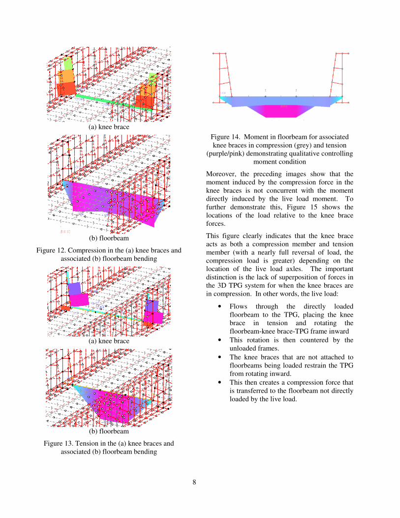
To further evaluate the system behavior, the
maximum compression condition (Figure 12) and
maximum tension (Figure 13) conditions are
isolated with their respective floorbeam bending.
Figure 11. Knee Brace flange forces for E80
Cooper loading
In Figure 12, the moment in floorbeam induced by
the compression knee braces; that is, the live load
is not directly loading the floorbeam.
In Figure 13, the moment is slightly reduced at the
knee braces. For this case the 80 kip axle from the
Cooper E-80 loading is directly over the
floorbeam and the moment is created directly by
live load from the rail.
For scale, the floorbeam bending moments shown
in the previous images are superimposed in Figure
14. The live load induced moments (purple/pink)
are more than double the knee brace-induced
moments (blue/grey).
8
(a) knee brace
(b) floorbeam
Figure 12. Compression in the (a) knee braces and
associated (b) floorbeam bending
(a) knee brace
(b) floorbeam
Figure 13. Tension in the (a) knee braces and
associated (b) floorbeam bending
Figure 14. Moment in floorbeam for associated
knee braces in compression (grey) and tension
(purple/pink) demonstrating qualitative controlling
moment condition
Moreover, the preceding images show that the
moment induced by the compression force in the
knee braces is not concurrent with the moment
directly induced by the live load moment. To
further demonstrate this, Figure 15 shows the
locations of the load relative to the knee brace
forces.
This figure clearly indicates that the knee brace
acts as both a compression member and tension
member (with a nearly full reversal of load, the
compression load is greater) depending on the
location of the live load axles. The important
distinction is the lack of superposition of forces in
the 3D TPG system for when the knee braces are
in compression. In other words, the live load:
• Flows through the directly loaded
floorbeam to the TPG, placing the knee
brace in tension and rotating the
floorbeam-knee brace-TPG frame inward
• This rotation is then countered by the
unloaded frames.
• The knee braces that are not attached to
floorbeams being loaded restrain the TPG
from rotating inward.
• This then creates a compression force that
is transferred to the floorbeam not directly
loaded by the live load.

9
Fig
ure
15
. T
hro
ugh
pla
te g
ird
er k
nee
bra
ce f
orc
es d
ispla
yed
rel
ativ
e to
po
siti
on
of
the
Liv
e L
oad
s.
Knee
bra
ces
sho
w t
ensi
on (
purp
le/p
ink
)
wh
ere
the
floo
rbea
ms
are
dir
ectl
y l
oad
ed a
nd
com
pre
ssio
n (
ora
ng
e/re
d)
wh
en i
n c
om
pre
ssio
n.
(No
te t
hat
the
purp
le s
ho
wn
at
the
cen
ter
of
the
spa
n i
s th
e ra
il d
um
my
mem
ber
fo
r lo
ad
dis
trib
uti
on
)
10
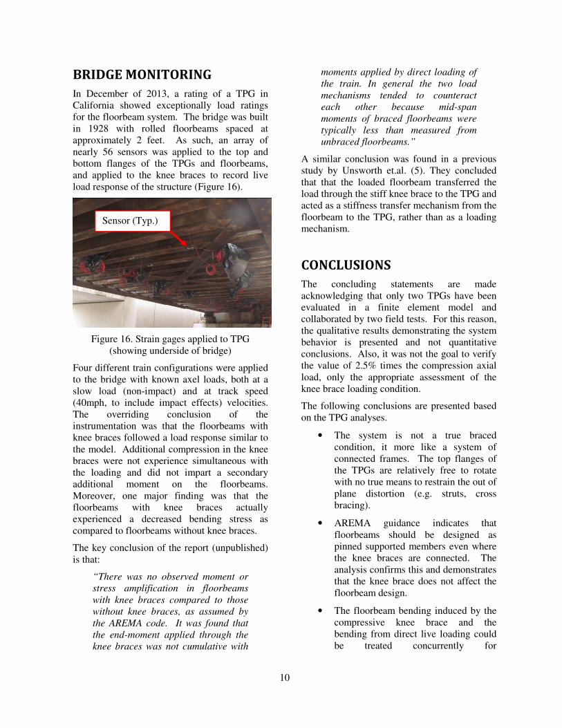
BRIDGE MONITORING
In December of 2013, a rating of a TPG in
California showed exceptionally load ratings
for the floorbeam system. The bridge was built
in 1928 with rolled floorbeams spaced at
approximately 2 feet. As such, an array of
nearly 56 sensors was applied to the top and
bottom flanges of the TPGs and floorbeams,
and applied to the knee braces to record live
load response of the structure (Figure 16).
Figure 16. Strain gages applied to TPG
(showing underside of bridge)
Four different train configurations were applied
to the bridge with known axel loads, both at a
slow load (non-impact) and at track speed
(40mph, to include impact effects) velocities.
The overriding conclusion of the
instrumentation was that the floorbeams with
knee braces followed a load response similar to
the model. Additional compression in the knee
braces were not experience simultaneous with
the loading and did not impart a secondary
additional moment on the floorbeams.
Moreover, one major finding was that the
floorbeams with knee braces actually
experienced a decreased bending stress as
compared to floorbeams without knee braces.
The key conclusion of the report (unpublished)
is that:
“There was no observed moment or
stress amplification in floorbeams
with knee braces compared to those
without knee braces, as assumed by
the AREMA code. It was found that
the end-moment applied through the
knee braces was not cumulative with
moments applied by direct loading of
the train. In general the two load
mechanisms tended to counteract
each other because mid-span
moments of braced floorbeams were
typically less than measured from
unbraced floorbeams.”
A similar conclusion was found in a previous
study by Unsworth et.al. (5). They concluded
that that the loaded floorbeam transferred the
load through the stiff knee brace to the TPG and
acted as a stiffness transfer mechanism from the
floorbeam to the TPG, rather than as a loading
mechanism.
CONCLUSIONS
The concluding statements are made
acknowledging that only two TPGs have been
evaluated in a finite element model and
collaborated by two field tests. For this reason,
the qualitative results demonstrating the system
behavior is presented and not quantitative
conclusions. Also, it was not the goal to verify
the value of 2.5% times the compression axial
load, only the appropriate assessment of the
knee brace loading condition.
The following conclusions are presented based
on the TPG analyses.
• The system is not a true braced
condition, it more like a system of
connected frames. The top flanges of
the TPGs are relatively free to rotate
with no true means to restrain the out of
plane distortion (e.g. struts, cross
bracing).
• AREMA guidance indicates that
floorbeams should be designed as
pinned supported members even where
the knee braces are connected. The
analysis confirms this and demonstrates
that the knee brace does not affect the
floorbeam design.
• The floorbeam bending induced by the
compressive knee brace and the
bending from direct live loading could
be treated concurrently for
Sensor (Typ.)
11
conservatism. In this case however, it
would be recommended to treat them as
a combination of longitudinal and
lateral forces (as indicated in 1.3.14.3)
with an increase in allowable of 25%.
This would still be considered
conservative since the estimated knee
brace induced moment on the
floorbeam is on the order of one half of
the direct live load bending moment.
• The resolution of the transverse force is
not such that a moment of (M = 2.5%
Axial x Depth of TPG) is created. The
force is resolved through the knee brace
frame action and imposed on the
floorbeam as a point load at the
connection away from the main point
of load.
• The model was also checked for a
continuously distributed E80 force of
8k per linear foot. In this load
condition, there were relatively small
tensile loads in the knee brace along the
member, and relatively small
compression force at bearings. The
floorbeam moments are not affected by
the knee brace loads, consistent with
the Cooper E-80 load conditions. This
would seem to indicate that when
evenly loaded, the floorbeam-knee
brace-TPG frame rotates inward evenly
along the length of the structure.
• It may be more appropriate to think of
the knee brace as a stiffness transfer
mechanism as noted in Galambos and
to avoid the confusion of the resolution
of the 2.5% notional load.
RECOMMENDATIONS
Based on the evidence from the model, the
transverse force of 2.5% times the axial load in
the braced compression member is appropriate,
but not be incorporated into the floorbeam
design. This force should, however, be used to
proportion the knee bracing.
Stated similarly, do not use the bracing force as
an induced moment, rather an axial force
resolved through the knee brace flange
(stiffened free edge). Conservatively, a 2.5%
axial load that represents the triangular
distribution of the 2.5% lateral load can be
placed as an additional axial force on the
floorbeam.
Don’t superimpose a knee brace moment of (M
= lateral load x depth of TPG) for the floorbeam
design with the bending moment induced by
direct live load.
It has been recommended to AREMA
Committee 15 for Steel Structures that the
following commentary language be
incorporated:
“The 2.5% proportioning force for
the brace is derived from a fixed point
restraint of the compression member
with an assumed initial out-of-
straightness. The intent of the article
is to establish the proper restraining
force imparted on the bracing
members that restrain against out-of-
plane displacement. For through
plate girders (TPG), the
proportioning force is not intended as
an additional design load to be
imparted on the structure, it is only a
value used to ensure that the
floorbeam-knee brace-TPG system
acts as a frame.”
FURTHER STUDY
During the investigation, it was noted that the
peak stresses in the knee brace are more
concentrated toward the outstanding portion of
the brace. This location is also the most
prevalent location of broken welds and popped
rivet heads as noted by field inspections. It is
recommended that further investigation could
improve this detail for increased TPG service
life.
Additionally, this project was limited to tangent
bridges without skew. The effects of curved
track and skew should also be investigated.
12
REFERENCES
1. Manual for Railway Engineering (2014),
Chapter 15, American Railway Engineering
and Maintenance-of-Way Association
(AREMA).
2. AASHTO (2012). LRFD bridge design
specifications, 6th Edition, American
Association of State Highway and
Transportation Officials, AASHTO,
Washington, DC.
3. Guide to Stability Design Criteria for Metal
Structures 5th Edition (1998), Theodore V.
Galambos, Wiley
4. Construction en bois: matériau,
technologie et Dimensionnement, Vol 13,
2004, Julius Natterer, Jean Luc Sandoz et
Martial Rey
5. Unsworth, J. Small, G., Afhami, S., Service
Load Investigation of the Composite
Behavior of a Ballasted Though Plate
Girder, Proceedings of the AREMA 2005
Annual Conference, June 15, 2005.