Embed Size (px)
Citation preview

Revision B
August 2018 TTKK 5566443333--55--MMMM--EENN
Rail EditionSLXi-DRCSingle Temperature Units
Maintenance Manual
©2020 Trane Technologies TK 56433-5-MM-EN
IntroductionThis manual is published for informational purposesonly. Thermo King® makes no representationswarranties express or implied, with respect to theinformation recommendations and descriptionscontained herein. Information provided should not beregarded as all-inclusive or covering all contingencies.If further information is required, Thermo KingCorporation Service Department should be consulted.
TThheerrmmoo KKiinngg’’ss wwaarrrraannttyy sshhaallll nnoott aappppllyy ttoo aannyyeeqquuiippmmeenntt wwhhiicchh hhaass bbeeeenn ““ssoo iinnssttaalllleedd,,mmaaiinnttaaiinneedd,, rreeppaaiirreedd oorr aalltteerreedd aass,, iinn tthheemmaannuuffaaccttuurreerr’’ss jjuuddggmmeenntt,, ttoo aaffffeecctt iittss iinntteeggrriittyy..””
MMaannuuffaaccttuurreerr sshhaallll hhaavvee nnoo lliiaabbiilliittyy ttoo aannyy ppeerrssoonnoorr eennttiittyy ffoorr aannyy ppeerrssoonnaall iinnjjuurryy,, pprrooppeerrttyy ddaammaaggeeoorr aannyy ootthheerr ddiirreecctt,, iinnddiirreecctt,, ssppeecciiaall,, oorrccoonnsseeqquueennttiiaall ddaammaaggeess wwhhaattssooeevveerr,, aarriissiinngg oouutt oofftthhee uussee ooff tthhiiss mmaannuuaall oorr aannyy iinnffoorrmmaattiioonn,,rreeccoommmmeennddaattiioonnss oorr ddeessccrriippttiioonnss ccoonnttaaiinneeddhheerreeiinn.. TThhee pprroocceedduurreess ddeessccrriibbeedd hheerreeiinn sshhoouullddoonnllyy bbee uunnddeerrttaakkeenn bbyy ssuuiittaabbllyy qquuaalliiffiieedd ppeerrssoonnnneell..FFaaiilluurree ttoo iimmpplleemmeenntt tthheessee pprroocceedduurreess ccoorrrreeccttllyymmaayy ccaauussee ddaammaaggee ttoo tthhee TThheerrmmoo KKiinngg uunniitt oorrootthheerr pprrooppeerrttyy oorr ppeerrssoonnaall iinnjjuurryy..
Revision HistoryRevision A (08/17) Original release
Revision B (08/18) Update R-404A to R-452A.
General InformationThe maintenance information in this manual covers unit models:
System SLXi-DRC (903708)
For further information, refer to:
SLXi-DRC Operator’s Manual TK 56402
SLXi-DRC Parts Manual TK 56471
SR-3 Trailer Single Temperature SL-400e, SLX/SLXe/SLXi Series Diagnostic Manual TK 56487
SLXi-DRC Diagrams Manual TK 56504
SLXi-DRC Single Temperature Installation Manual TK 56403
TK482 and TK486 Engine Overhaul Manual TK 50136
X214, X418, X426 and X430 Compressor Overhaul Manual TK 6875
Diagnosing Thermo King Truck and Trailer Refrigeration Systems TK 5984
Tool Catalog TK 5955
Evacuation Station Operation and Field Application TK 40612
The information in this manual is provided to assist owners, operators and service people in the proper upkeep and maintenance of ThermoKing units.

TK 56433-5-MM-EN 3
Recover RefrigerantNNoottee:: In the USA, EPA Section 608 Certification is
required to work on refrigeration systems. In theEU, local F-gas Regulations must be observedwhen working on refrigeration systems.
At Thermo King®, we recognize the need to preservethe environment and limit the potential harm to theozone layer that can result from allowing refrigerant toescape into the atmosphere.
We strictly adhere to a policy that promotes therecovery and limits the loss of refrigerant into theatmosphere.
When working on transport temperature controlsystems, a recovery process that prevents or minimizesrefrigerant loss to the atmosphere is required by law. Inaddition, service personnel must be aware of theappropriate European Union, National, Federal, State,and/or Local regulations governing the use ofrefrigerants and certification of technicians. Foradditional information on regulations and technicianprograms, contact your local THERMO KING dealer.
SSeerrvviiccee TToooollss - Use the proper service tools. Gaugemanifold sets should include appropriate shutoffvalves or disconnects near the end of each service line.
RReeccoovveerryy EEqquuiippmmeenntt - Recovery equipment must beused. Proper recovering, storing and recycling ofrefrigerants is an important part of all service work.
SSeerrvviiccee PPrroocceedduurreess - Recommended procedures mustbe used to minimize refrigerant loss.
CCoommppoonneennttss mmaayy bbee iissoollaatteedd by closing servicevalves and performing system pump-downs.
CCoommppoonneennttss uunnaabbllee ttoo bbee iissoollaatteedd for service mustbe repaired only after refrigerant is properly recovered.
Customer Satisfaction SurveyLet your voice be heard!
Your feedback will help improve our manuals. Thesurvey is accessible through any internet-connecteddevice with a web browser.
Scan the Quick Response (QR) code or click or type theweb address https://tranetechnologies.iad1.qualtrics.com/jfe/form/SV_2octfSHoUJxsk6x?Q_CHL=qr&Q_JFE=qdg to complete the survey.
IInnttrroodduuccttiioonn
4 TK 56433-5-MM-EN
SSaaffeettyy PPrreeccaauuttiioonnss .. .. .. .. .. .. .. .. .. .. .. .. .. .. .. .. .. .. .. .. .. .. .. .. 88Danger, Warning, Caution, andNotice . . . . . . . . . . . . . . . . . . . . . . . . . . . . . . . . . . . 8
General Practices . . . . . . . . . . . . . . . . . . . . . . . . . 8
Battery Installation and CableRouting . . . . . . . . . . . . . . . . . . . . . . . . . . . . . . . . . . 9
Battery Removal. . . . . . . . . . . . . . . . . . . . . . . . . . 9
Refrigerant Hazards. . . . . . . . . . . . . . . . . . . . . . 10
Refrigerant Oil Hazards. . . . . . . . . . . . . . . . . . . 10
Electrical Hazards. . . . . . . . . . . . . . . . . . . . . . . . 10Low Voltage . . . . . . . . . . . . . . . . . . . . . . . . . 10
Microprocessor Service Precautions . . . . . . 11
Welding Precautions . . . . . . . . . . . . . . . . . . . . . 11
First Aid . . . . . . . . . . . . . . . . . . . . . . . . . . . . . . . . 12
SSppeecciiffiiccaattiioonnss .. .. .. .. .. .. .. .. .. .. .. .. .. .. .. .. .. .. .. .. .. .. .. .. .. .. .. .. 1133Engine . . . . . . . . . . . . . . . . . . . . . . . . . . . . . . . . . . 13
Belt Tension. . . . . . . . . . . . . . . . . . . . . . . . . . . . . 14
Refrigeration System . . . . . . . . . . . . . . . . . . . . 14
Electrical Control System. . . . . . . . . . . . . . . . . 14
Electrical Components . . . . . . . . . . . . . . . . . . . 15
MMaaiinntteennaannccee IInnssppeeccttiioonnSScchheedduullee .. .. .. .. .. .. .. .. .. .. .. .. .. .. .. .. .. .. .. .. .. .. .. .. .. .. .. .. .. .. .. .. .. 1166
UUnniitt DDeessccrriippttiioonn.. .. .. .. .. .. .. .. .. .. .. .. .. .. .. .. .. .. .. .. .. .. .. .. .. .. 1188Unit Overview . . . . . . . . . . . . . . . . . . . . . . . . . . . 18
Design Features . . . . . . . . . . . . . . . . . . . . . . . . . 18Diesel Engine . . . . . . . . . . . . . . . . . . . . . . . . 18Thermo King X430 SeriesReciprocating Compressor. . . . . . . . . . . . 18Electronic Throttling Valve . . . . . . . . . . . . 18SMART REEFER 3 (SR-3) ControlSystem. . . . . . . . . . . . . . . . . . . . . . . . . . . . . . 19CYCLE-SENTRY™ Start-StopControls. . . . . . . . . . . . . . . . . . . . . . . . . . . . . 19Data Logging . . . . . . . . . . . . . . . . . . . . . . . . 19TK BlueBox. . . . . . . . . . . . . . . . . . . . . . . . . . 20CargoLink™ . . . . . . . . . . . . . . . . . . . . . . . . . 20OptiSet Plus™ . . . . . . . . . . . . . . . . . . . . . . . 21FreshSet™ . . . . . . . . . . . . . . . . . . . . . . . . . . 21
Sequence of Operation. . . . . . . . . . . . . . . . . . . 21Operating Modes . . . . . . . . . . . . . . . . . . . . 21
Defrost . . . . . . . . . . . . . . . . . . . . . . . . . . . . 21
Engine Compartment Components. . . . . . . . 22
Unit Protection Devices . . . . . . . . . . . . . . . . . . 22
Serial Number Locations . . . . . . . . . . . . . . . . . 22
EElleeccttrriiccaall MMaaiinntteennaannccee .. .. .. .. .. .. .. .. .. .. .. .. .. .. .. .. .. .. 2255Alternator Diagnostic Procedures . . . . . . . . . 25
General Information. . . . . . . . . . . . . . . . . . 25Alternator Identification . . . . . . . . . . . . . . 25Base Controller Fuse F4. . . . . . . . . . . . . . . 25Test Equipment for Checking Voltageand Current. . . . . . . . . . . . . . . . . . . . . . . . . . 25Alternator Load Test . . . . . . . . . . . . . . . . . 26General Diagnostic and WarrantyEvaluation Procedure. . . . . . . . . . . . . . . . . 26Field Current Test . . . . . . . . . . . . . . . . . . . . 27
Battery. . . . . . . . . . . . . . . . . . . . . . . . . . . . . . . . . . 27Filler Cap Batteries . . . . . . . . . . . . . . . . . . . 27Maintenance Free Batteries . . . . . . . . . . . 27Battery Load Test . . . . . . . . . . . . . . . . . . . . 28
Battery Cables. . . . . . . . . . . . . . . . . . . . . . . . . . . 28
Base Controller . . . . . . . . . . . . . . . . . . . . . . . . . . 28Base Controller Fuse Size &Function . . . . . . . . . . . . . . . . . . . . . . . . . . . . 28
Fuse F10 . . . . . . . . . . . . . . . . . . . . . . . . . . . 28Fuse F15 . . . . . . . . . . . . . . . . . . . . . . . . . . . 29
LED Functions . . . . . . . . . . . . . . . . . . . . . . . 29Smart FET Outputs . . . . . . . . . . . . . . . . . . . 29
SMART REEFER 3 (SR-3) MicroprocessorController . . . . . . . . . . . . . . . . . . . . . . . . . . . . . . . 29
Fuse Link . . . . . . . . . . . . . . . . . . . . . . . . . . . . . . . 29
Air Heater . . . . . . . . . . . . . . . . . . . . . . . . . . . . . . . 30
Unit Wiring . . . . . . . . . . . . . . . . . . . . . . . . . . . . . 30
Wire Harness Routing . . . . . . . . . . . . . . . . . . . . 30
EEnnggiinnee MMaaiinntteennaannccee .. .. .. .. .. .. .. .. .. .. .. .. .. .. .. .. .. .. .. .. .. 3311EMI 3000. . . . . . . . . . . . . . . . . . . . . . . . . . . . . . . . 31
Engine Lubrication System . . . . . . . . . . . . . . . 31Engine Oil Change . . . . . . . . . . . . . . . . . . . 31Oil Filter Change . . . . . . . . . . . . . . . . . . . . . 31Low Oil Pressure . . . . . . . . . . . . . . . . . . . . . 31
Engine Cooling System . . . . . . . . . . . . . . . . . . 32Extended Life Coolant (ELC). . . . . . . . . . . 33
Table of Contents

TK 56433-5-MM-EN 5
Antifreeze MaintenanceProcedure . . . . . . . . . . . . . . . . . . . . . . . . . . . 33
Checking the Antifreeze. . . . . . . . . . . . . . . 33Changing the Antifreeze . . . . . . . . . . . . . . 33
Bleeding Air from the CoolingSystem. . . . . . . . . . . . . . . . . . . . . . . . . . . . . . 33Engine Thermostat . . . . . . . . . . . . . . . . . . . 34Coolant Level Switch . . . . . . . . . . . . . . . . . 34
Testing the Coolant Level Switch . . . . . . . 34Checking the Float . . . . . . . . . . . . . . . . . . . 35Replacing the Coolant LevelSwitch . . . . . . . . . . . . . . . . . . . . . . . . . . . . . 35
Engine Fuel System. . . . . . . . . . . . . . . . . . . . . . 35Operation . . . . . . . . . . . . . . . . . . . . . . . . . . . 35Fuel Line Routing . . . . . . . . . . . . . . . . . . . . 35Maintenance . . . . . . . . . . . . . . . . . . . . . . . . 35Fuel Return Line Replacement. . . . . . . . . 37Bleeding the Fuel System. . . . . . . . . . . . . 37Draining Water from Fuel Tank . . . . . . . . 38Fuel Pre-Strainer . . . . . . . . . . . . . . . . . . . . . 38Fuel Filter/Water Separator . . . . . . . . . . . 39Fuel Filter/Water SeparatorReplacement . . . . . . . . . . . . . . . . . . . . . . . . 39Engine Speed Adjustments . . . . . . . . . . . 39
High Speed. . . . . . . . . . . . . . . . . . . . . . . . . 39Low Speed . . . . . . . . . . . . . . . . . . . . . . . . . 39
Injection Pump Timing . . . . . . . . . . . . . . . 40Injection Pump Removal. . . . . . . . . . . . . . 43Injection Pump Reinstallation . . . . . . . . . 44Fuel Solenoid . . . . . . . . . . . . . . . . . . . . . . . . 44
Testing the Fuel Solenoid . . . . . . . . . . . . . 45Fuel Solenoid Replacement . . . . . . . . . . . 46
Trochoid Feed Pump . . . . . . . . . . . . . . . . . 46Trochoid Feed Pump Leaks . . . . . . . . . . . . 47Trochoid Feed PumpReplacement . . . . . . . . . . . . . . . . . . . . . . . 47
Cold Start Device . . . . . . . . . . . . . . . . . . . . 48Checking Cold Start DeviceOperation . . . . . . . . . . . . . . . . . . . . . . . . . . 48Cold Start Device Replacement . . . . . . . . 48
Engine Valve Clearance Adjustment. . . . . . . 49
Crankcase Breather . . . . . . . . . . . . . . . . . . . . . . 50
EMI 3000 Air Cleaner. . . . . . . . . . . . . . . . . . . . . 51
Belts. . . . . . . . . . . . . . . . . . . . . . . . . . . . . . . . . . . . 51Fan Drive Belt. . . . . . . . . . . . . . . . . . . . . . . . 52
Fan Drive Belt Replacement . . . . . . . . . . . 52Fan Drive Belt Adjustment . . . . . . . . . . . . 54
Engine/Cross Shaft Belt. . . . . . . . . . . . . . . 55
Assembly of Tensioner Clutch . . . . . . . . . 56Engine/Cross Shaft BeltReplacement . . . . . . . . . . . . . . . . . . . . . . . 56
Water Pump Belt . . . . . . . . . . . . . . . . . . . . . 58
RReeffrriiggeerraattiioonn MMaaiinntteennaannccee .. .. .. .. .. .. .. .. .. .. .. .. .. .. 5599Refrigerant Charge . . . . . . . . . . . . . . . . . . . . . . 59
Testing The Refrigerant Charge WithAn Empty Trailer . . . . . . . . . . . . . . . . . . . . . 59Testing the Refrigerant Charge witha Loaded Trailer . . . . . . . . . . . . . . . . . . . . . 59Testing for an Overcharge . . . . . . . . . . . . 59
Moisture Indicating Sight Glass . . . . . . . . . . . 60
Refrigerant Leaks . . . . . . . . . . . . . . . . . . . . . . . . 60
Checking Compressor Oil . . . . . . . . . . . . . . . . 60
High Pressure Cutout Switch(HPCO) . . . . . . . . . . . . . . . . . . . . . . . . . . . . . . . . . 61
Three-Way Valve Condenser PressureBypass Check Valve. . . . . . . . . . . . . . . . . . . . . . 61
Electronic Throttling Valve (ETV) . . . . . . . . . . 62
Pressure Transducers . . . . . . . . . . . . . . . . . . . . 63
Hot Gas Bypass Valve . . . . . . . . . . . . . . . . . . . . 63
RReeffrriiggeerraattiioonn SSeerrvviiccee OOppeerraattiioonnss .. .. .. .. .. .. .. 6644Refrigeration System Components . . . . . . . . 64
Compressor . . . . . . . . . . . . . . . . . . . . . . . . . . . . . 65Removal . . . . . . . . . . . . . . . . . . . . . . . . . . . . 65Installation . . . . . . . . . . . . . . . . . . . . . . . . . . 65Compressor Coupling Removal(Standard Units) . . . . . . . . . . . . . . . . . . . . . 65Compressor Coupling Installation(Standard Units) . . . . . . . . . . . . . . . . . . . . . 66
Compressors with Pressurized SealCavity . . . . . . . . . . . . . . . . . . . . . . . . . . . . . . . . . . 67
Hex Drive Compressor SealReplacement . . . . . . . . . . . . . . . . . . . . . . . . . . . . 68
Condenser Coil . . . . . . . . . . . . . . . . . . . . . . . . . . 70Removal . . . . . . . . . . . . . . . . . . . . . . . . . . . . 70Installation . . . . . . . . . . . . . . . . . . . . . . . . . . 70
Discharge Vibrasorber . . . . . . . . . . . . . . . . . . . 70Removal . . . . . . . . . . . . . . . . . . . . . . . . . . . . 70Installation . . . . . . . . . . . . . . . . . . . . . . . . . . 70
In-Line Condenser Check Valve . . . . . . . . . . . 71
TTaabbllee ooff CCoonntteennttss

6 TK 56433-5-MM-EN
Condenser Check ValveReplacement . . . . . . . . . . . . . . . . . . . . . . . . . . . . 71
Removal . . . . . . . . . . . . . . . . . . . . . . . . . . . . 71Installation . . . . . . . . . . . . . . . . . . . . . . . . . . 71
Bypass Check Valve. . . . . . . . . . . . . . . . . . . . . . 71Removal . . . . . . . . . . . . . . . . . . . . . . . . . . . . 71Installation . . . . . . . . . . . . . . . . . . . . . . . . . . 71
Receiver Tank . . . . . . . . . . . . . . . . . . . . . . . . . . . 71Removal . . . . . . . . . . . . . . . . . . . . . . . . . . . . 71Installation . . . . . . . . . . . . . . . . . . . . . . . . . . 71
Filter-Drier . . . . . . . . . . . . . . . . . . . . . . . . . . . . . . 72Removal . . . . . . . . . . . . . . . . . . . . . . . . . . . . 72Installation . . . . . . . . . . . . . . . . . . . . . . . . . . 72
Expansion Valve Assembly . . . . . . . . . . . . . . . 72Removal . . . . . . . . . . . . . . . . . . . . . . . . . . . . 72Installation . . . . . . . . . . . . . . . . . . . . . . . . . . 72
Heat Exchanger . . . . . . . . . . . . . . . . . . . . . . . . . 72Removal . . . . . . . . . . . . . . . . . . . . . . . . . . . . 72Installation . . . . . . . . . . . . . . . . . . . . . . . . . . 73
Evaporator Coil Assembly . . . . . . . . . . . . . . . . 73Removal . . . . . . . . . . . . . . . . . . . . . . . . . . . . 73Installation . . . . . . . . . . . . . . . . . . . . . . . . . . 73
Accumulator . . . . . . . . . . . . . . . . . . . . . . . . . . . . 73Removal . . . . . . . . . . . . . . . . . . . . . . . . . . . . 73Installation . . . . . . . . . . . . . . . . . . . . . . . . . . 73
Three-Way Valve Repair. . . . . . . . . . . . . . . . . . 74Removal/Disassembly . . . . . . . . . . . . . . . . 74End Cap Checks. . . . . . . . . . . . . . . . . . . . . . 75
Check Valve Bleed Hole Diameter . . . . . . 75Assembly/Installation . . . . . . . . . . . . . . . . 76
Three-Way Valve Condenser PressureBypass Check Valve Repair . . . . . . . . . . . . . . . 77
Removal . . . . . . . . . . . . . . . . . . . . . . . . . . . . 77Installation . . . . . . . . . . . . . . . . . . . . . . . . . . 77
Pilot Solenoid . . . . . . . . . . . . . . . . . . . . . . . . . . . 77Removal . . . . . . . . . . . . . . . . . . . . . . . . . . . . 77Installation . . . . . . . . . . . . . . . . . . . . . . . . . . 77
Suction Vibrasorber . . . . . . . . . . . . . . . . . . . . . 77Removal . . . . . . . . . . . . . . . . . . . . . . . . . . . . 77Installation . . . . . . . . . . . . . . . . . . . . . . . . . . 78
High Pressure Cutout Switch . . . . . . . . . . . . . 78Removal . . . . . . . . . . . . . . . . . . . . . . . . . . . . 78Installation . . . . . . . . . . . . . . . . . . . . . . . . . . 78
High Pressure Relief Valve. . . . . . . . . . . . . . . . 78Removal . . . . . . . . . . . . . . . . . . . . . . . . . . . . 78Installation . . . . . . . . . . . . . . . . . . . . . . . . . . 78
Discharge Pressure Transducer . . . . . . . . . . . 78Removal . . . . . . . . . . . . . . . . . . . . . . . . . . . . 78Installation . . . . . . . . . . . . . . . . . . . . . . . . . . 78
Suction Pressure Transducer . . . . . . . . . . . . . 78Removal . . . . . . . . . . . . . . . . . . . . . . . . . . . . 78Installation . . . . . . . . . . . . . . . . . . . . . . . . . . 78
Electronic Throttling Valve (ETV) . . . . . . . . . . 79Removal . . . . . . . . . . . . . . . . . . . . . . . . . . . . 79Installation of Service Kit . . . . . . . . . . . . . 80Installation of Complete ETVAssembly . . . . . . . . . . . . . . . . . . . . . . . . . . . 81
Hot Gas Bypass Valve . . . . . . . . . . . . . . . . . . . . 81Removal . . . . . . . . . . . . . . . . . . . . . . . . . . . . 81Installation . . . . . . . . . . . . . . . . . . . . . . . . . . 81
Compressors with Internal Oil Filter . . . . . . . 81Internal Oil Filter Replacement . . . . . . . . 81
Checking Compressor Oil Pressure. . . . . . . . 82
SSttrruuccttuurraall MMaaiinntteennaannccee.. .. .. .. .. .. .. .. .. .. .. .. .. .. .. .. .. .. 8844Unit and Engine Mounting Bolts . . . . . . . . . . 84
Unit Inspection . . . . . . . . . . . . . . . . . . . . . . . . . . 84
Condenser, Evaporator, and RadiatorCoils. . . . . . . . . . . . . . . . . . . . . . . . . . . . . . . . . . . . 84
Micro-Channel Coil CleaningRecommendations . . . . . . . . . . . . . . . . . . . 84
Cleaning Intervals . . . . . . . . . . . . . . . . . . . 84Cleaning Methods . . . . . . . . . . . . . . . . . . . 84
Defrost Drains . . . . . . . . . . . . . . . . . . . . . . . . . . . 85
Unit Installation . . . . . . . . . . . . . . . . . . . . . . . . . 85
Defrost Damper . . . . . . . . . . . . . . . . . . . . . . . . . 85Testing Defrost Damper . . . . . . . . . . . . . . 86Troubleshooting DefrostDamper . . . . . . . . . . . . . . . . . . . . . . . . . . . . . 86Replacing Damper Gear Motor . . . . . . . . 87
Condenser and Evaporator FanLocation . . . . . . . . . . . . . . . . . . . . . . . . . . . . . . . . 87
Condenser Inlet OrificeAlignment . . . . . . . . . . . . . . . . . . . . . . . . . . . 87Evaporator Fan BlowerAlignment . . . . . . . . . . . . . . . . . . . . . . . . . . . 87
TTaabbllee ooff CCoonntteennttss

TK 56433-5-MM-EN 7
Fan Shaft Assembly. . . . . . . . . . . . . . . . . . . . . . 88Removal . . . . . . . . . . . . . . . . . . . . . . . . . . . . 88Disassembly. . . . . . . . . . . . . . . . . . . . . . . . . 88Reassembly . . . . . . . . . . . . . . . . . . . . . . . . . 88Installation . . . . . . . . . . . . . . . . . . . . . . . . . . 90
Lower Condenser Blower Assembly. . . . . . . 90Removal . . . . . . . . . . . . . . . . . . . . . . . . . . . . 90Disassembly. . . . . . . . . . . . . . . . . . . . . . . . . 90Reassembly . . . . . . . . . . . . . . . . . . . . . . . . . 91Installation . . . . . . . . . . . . . . . . . . . . . . . . . . 91
Cross Shaft Assembly. . . . . . . . . . . . . . . . . . . . 91Removal . . . . . . . . . . . . . . . . . . . . . . . . . . . . 91Disassembly. . . . . . . . . . . . . . . . . . . . . . . . . 91Reassembly . . . . . . . . . . . . . . . . . . . . . . . . . 92
Installation . . . . . . . . . . . . . . . . . . . . . . . . . . 92
Idler Assemblies. . . . . . . . . . . . . . . . . . . . . . . . . 92Disassembly. . . . . . . . . . . . . . . . . . . . . . . . . 92Reassembly . . . . . . . . . . . . . . . . . . . . . . . . . 93
MMeecchhaanniiccaall DDiiaaggnnoossiiss .. .. .. .. .. .. .. .. .. .. .. .. .. .. .. .. .. .. .. 9944
RReeffrriiggeerraattiioonn DDiiaaggnnoossiiss .. .. .. .. .. .. .. .. .. .. .. .. .. .. .. .. .. 9977
RReeffrriiggeerraattiioonn DDiiaaggrraammss.. .. .. .. .. .. .. .. .. .. .. .. .. .. .. .. .. .. 9999Cool Cycle . . . . . . . . . . . . . . . . . . . . . . . . . . . . . . 99
Heat/Defrost Cycle . . . . . . . . . . . . . . . . . . . . . . 101
DDiiaaggrraamm IInnddeexx.. .. .. .. .. .. .. .. .. .. .. .. .. .. .. .. .. .. .. .. .. .. .. .. .. .. ..110033
TTaabbllee ooff CCoonntteennttss
8 TK 56433-5-MM-EN
Safety PrecautionsDanger, Warning, Caution, andNoticeThermo King® recommends that all service beperformed by a Thermo King dealer and to be aware ofseveral general safety practices.
Safety advisories appear throughout this manual asrequired. Your personal safety and the properoperation of this unit depend upon the strictobservance of these precautions.
Indicates an imminently hazardoussituation which, if not avoided, willresult in death or serious injury.
Indicates a potentially hazardoussituation which, if not avoided, couldresult in death or serious injury.
Indicates a potentially hazardoussituation which, if not avoided, couldresult in minor or moderate injury andunsafe practices.
Indicates a situation that could resultin equipment or property-damage onlyaccidents.
General PracticesDDAANNGGEERR
HHaazzaarrdd ooff EExxpplloossiioonn!!NNeevveerr aappppllyy hheeaatt ttoo aa sseeaalleedd rreeffrriiggeerraattiioonn ssyysstteemmoorr ccoonnttaaiinneerr.. HHeeaatt iinnccrreeaasseess iinntteerrnnaall pprreessssuurree,,wwhhiicchh mmiigghhtt ccaauussee aann eexxpplloossiioonn rreessuullttiinngg iinn ddeeaatthhoorr sseerriioouuss iinnjjuurryy..
DDAANNGGEERRHHaazzaarrddoouuss GGaasseess!!RReeffrriiggeerraanntt iinn tthhee pprreesseennccee ooff aann ooppeenn ffllaammee,,ssppaarrkk,, oorr eelleeccttrriiccaall sshhoorrtt pprroodduucceess ttooxxiicc ggaasseess tthhaattaarree sseevveerree rreessppiirraattoorryy iirrrriittaannttss wwhhiicchh ccaann ccaauusseesseerriioouuss iinnjjuurryy oorr ppoossssiibbllee ddeeaatthh..
DDAANNGGEERRRRiisskk ooff IInnjjuurryy!!KKeeeepp yyoouurr hhaannddss,, ccllootthhiinngg,, aanndd ttoooollss cclleeaarr ooff ffaannssaanndd//oorr bbeellttss wwhheenn wwoorrkkiinngg oonn aa uunniitt tthhaatt iissrruunnnniinngg oorr wwhheenn ooppeenniinngg oorr cclloossiinngg ccoommpprreessssoorrsseerrvviiccee vvaallvveess.. LLoooossee ccllootthhiinngg mmiigghhtt eennttaanngglleemmoovviinngg ppuulllleeyyss oorr bbeellttss,, ccaauussiinngg sseerriioouuss iinnjjuurryy oorrppoossssiibbllee ddeeaatthh..
DDAANNGGEERRRReeffrriiggeerraanntt VVaappoorr HHaazzaarrdd!!DDoo nnoott iinnhhaallee rreeffrriiggeerraanntt.. UUssee ccaauuttiioonn wwhheennwwoorrkkiinngg wwiitthh rreeffrriiggeerraanntt oorr aa rreeffrriiggeerraattiioonn ssyysstteemmiinn aannyy ccoonnffiinneedd aarreeaa wwiitthh aa lliimmiitteedd aaiirr ssuuppppllyy..RReeffrriiggeerraanntt ddiissppllaacceess aaiirr aanndd ccaann ccaauussee ooxxyyggeennddeepplleettiioonn,, rreessuullttiinngg iinn ssuuffffooccaattiioonn aanndd ppoossssiibblleeddeeaatthh..
DDAANNGGEERRCCoonnffiinneedd SSppaaccee HHaazzaarrddss!!AAvvooiidd eennggiinnee ooppeerraattiioonn iinn ccoonnffiinneedd ssppaacceess aannddaarreeaass oorr cciirrccuummssttaanncceess wwhheerree ffuummeess ffrroomm tthheeeennggiinnee ccoouulldd bbeeccoommee ttrraappppeedd aanndd ccaauussee sseerriioouussiinnjjuurryy oorr ddeeaatthh..
WWAARRNNIINNGGHHaazzaarrdd ooff EExxpplloossiioonn!!NNeevveerr cclloossee tthhee ccoommpprreessssoorr ddiisscchhaarrggee sseerrvviicceevvaallvvee wwhheenn tthhee uunniitt iiss ooppeerraattiinngg.. NNeevveerr ooppeerraatteetthhee uunniitt wwiitthh tthhee ddiisscchhaarrggee vvaallvvee cclloosseedd ((ffrroonnttsseeaatteedd)).. TThhiiss ccoonnddiittiioonn iinnccrreeaasseess iinntteerrnnaallpprreessssuurree,, wwhhiicchh ccaann ccaauussee aann eexxpplloossiioonn..
WWAARRNNIINNGGPPrrooppeerr EEqquuiippmmeenntt CCoonnddiittiioonn!!GGaauuggee mmaanniiffoolldd hhoosseess mmuusstt bbee iinn ggoooodd ccoonnddiittiioonnbbeeffoorree uussiinngg tthheemm.. NNeevveerr lleett tthheemm ccoommee iinn ccoonnttaaccttwwiitthh mmoovviinngg bbeellttss,, ffaannss,, ppuulllleeyyss oorr hhoott ssuurrffaacceess..DDeeffeeccttiivvee ggaauuggee eeqquuiippmmeenntt ccaann ddaammaaggeeccoommppoonneennttss oorr ccaauussee sseerriioouuss iinnjjuurryy..
WWAARRNNIINNGGPPeerrssoonnaall PPrrootteeccttiivvee EEqquuiippmmeenntt ((PPPPEE))RReeqquuiirreedd!!AAllwwaayyss wweeaarr ggoogggglleess oorr ssaaffeettyy ggllaasssseess wwhheennwwoorrkkiinngg oonn aa uunniitt.. RReeffrriiggeerraanntt lliiqquuiidd,, ooiill,, aannddbbaatttteerryy aacciidd ccaann ppeerrmmaanneennttllyy ddaammaaggee yyoouurr eeyyeess..SSeeee ““FFiirrsstt AAiidd””..
WWAARRNNIINNGGEEqquuiippmmeenntt DDaammaaggee aanndd RRiisskk ooffIInnjjuurryy!!NNeevveerr ddrriillll hhoolleess iinnttoo tthhee uunniitt uunnlleessss iinnssttrruucctteedd bbyyTThheerrmmoo KKiinngg.. HHoolleess ddrriilllleedd iinnttoo hhiigghh vvoollttaaggeeccaabblleess ccoouulldd ccaauussee aann eelleeccttrriiccaall ffiirree,, sseevveerreeppeerrssoonnaall iinnjjuurryy,, oorr eevveenn ddeeaatthh..

TK 56433-5-MM-EN 9
WWAARRNNIINNGGRRiisskk ooff IInnjjuurryy!!WWhheenn uussiinngg llaaddddeerrss ttoo iinnssttaallll oorr sseerrvviicceerreeffrriiggeerraattiioonn ssyysstteemmss,, aallwwaayyss oobbsseerrvvee tthhee llaaddddeerrmmaannuuffaaccttuurreerr’’ss ssaaffeettyy llaabbeellss aanndd wwaarrnniinnggss.. AA wwoorrkkppllaattffoorrmm oorr ssccaaffffoollddiinngg iiss tthhee rreeccoommmmeennddeeddmmeetthhoodd ffoorr iinnssttaallllaattiioonnss aanndd sseerrvviicciinngg..
CCAAUUTTIIOONNSShhaarrpp EEddggeess!!EExxppoosseedd ccooiill ffiinnss ccaann ccaauussee llaacceerraattiioonnss.. SSeerrvviicceewwoorrkk oonn tthhee eevvaappoorraattoorr oorr ccoonnddeennsseerr ccooiillss iiss bbeessttlleefftt ttoo aa cceerrttiiffiieedd TThheerrmmoo KKiinngg tteecchhnniicciiaann..
NNOOTTIICCEEEEqquuiippmmeenntt DDaammaaggee!!AAllll mmoouunnttiinngg bboollttss mmuusstt bbee tthhee ccoorrrreecctt lleennggtthh ffoorrtthheeiirr aapppplliiccaattiioonnss aanndd ttoorrqquueedd ttoo ssppeecciiffiiccaattiioonn..IInnccoorrrreecctt bboolltt lleennggtthhss aanndd iimmpprrooppeerr ttoorrqquueessppeecciiffiiccaattiioonnss ccaann ddaammaaggee eeqquuiippmmeenntt..
Battery Installation and CableRouting
WWAARRNNIINNGGHHaazzaarrdd ooff EExxpplloossiioonn!!AAnn iimmpprrooppeerrllyy iinnssttaalllleedd bbaatttteerryy ccoouulldd rreessuulltt iinn aaffiirree,, eexxpplloossiioonn,, oorr iinnjjuurryy.. AA TThheerrmmoo KKiinngg aapppprroovveeddbbaatttteerryy mmuusstt bbee iinnssttaalllleedd aanndd pprrooppeerrllyy sseeccuurreedd ttootthhee bbaatttteerryy ttrraayy..
WWAARRNNIINNGGHHaazzaarrdd ooff EExxpplloossiioonn!!IImmpprrooppeerrllyy iinnssttaalllleedd bbaatttteerryy ccaabblleess ccoouulldd rreessuulltt iinnaa ffiirree,, eexxpplloossiioonn,, oorr iinnjjuurryy.. BBaatttteerryy ccaabblleess mmuusstt bbeeiinnssttaalllleedd,, rroouutteedd,, aanndd sseeccuurreedd pprrooppeerrllyy ttoo pprreevveenntttthheemm ffrroomm rruubbbbiinngg,, cchhaaffffiinngg,, oorr mmaakkiinngg ccoonnttaaccttwwiitthh hhoott,, sshhaarrpp,, oorr rroottaattiinngg ccoommppoonneennttss..
WWAARRNNIINNGGFFiirree HHaazzaarrdd!!DDoo nnoott aattttaacchh ffuueell lliinneess ttoo bbaatttteerryy ccaabblleess oorreelleeccttrriiccaall hhaarrnneesssseess.. TThhiiss hhaass tthhee ppootteennttiiaall ttooccaauussee aa ffiirree aanndd ccoouulldd ccaauussee sseerriioouuss iinnjjuurryy oorrddeeaatthh..
WWAARRNNIINNGGPPeerrssoonnaall PPrrootteeccttiivvee EEqquuiippmmeenntt ((PPPPEE))RReeqquuiirreedd!!AA bbaatttteerryy ccaann bbee ddaannggeerroouuss.. AA bbaatttteerryy ccoonnttaaiinnss aaffllaammmmaabbllee ggaass tthhaatt ccaann iiggnniittee oorr eexxppllooddee.. AAbbaatttteerryy ssttoorreess eennoouugghh eelleeccttrriicciittyy ttoo bbuurrnn yyoouu iiff iittddiisscchhaarrggeess qquuiicckkllyy.. AA bbaatttteerryy ccoonnttaaiinnss bbaatttteerryy aacciiddtthhaatt ccaann bbuurrnn yyoouu.. AAllwwaayyss wweeaarr ggoogggglleess oorr ssaaffeettyyggllaasssseess aanndd ppeerrssoonnaall pprrootteeccttiivvee eeqquuiippmmeenntt wwhheennwwoorrkkiinngg wwiitthh aa bbaatttteerryy.. IIff yyoouu ggeett bbaatttteerryy aacciidd oonnyyoouu,, iimmmmeeddiiaatteellyy fflluusshh iitt wwiitthh wwaatteerr aanndd ggeettmmeeddiiccaall aatttteennttiioonn..
WWAARRNNIINNGGHHaazzaarrdd ooff EExxpplloossiioonn!!AAllwwaayyss ccoovveerr bbaatttteerryy tteerrmmiinnaallss ttoo pprreevveenntt tthheemmffrroomm mmaakkiinngg ccoonnttaacctt wwiitthh mmeettaall ccoommppoonneennttssdduurriinngg bbaatttteerryy iinnssttaallllaattiioonn.. BBaatttteerryy tteerrmmiinnaallssggrroouunnddiinngg aaggaaiinnsstt mmeettaall ccoouulldd ccaauussee tthhee bbaatttteerryyttoo eexxppllooddee..
CCAAUUTTIIOONNHHaazzaarrddoouuss SSeerrvviiccee PPrroocceedduurreess!!SSeett aallll uunniitt eelleeccttrriiccaall ccoonnttrroollss ttoo tthhee OOFFFF ppoossiittiioonnbbeeffoorree ccoonnnneeccttiinngg bbaatttteerryy ccaabblleess ttoo tthhee bbaatttteerryy ttoopprreevveenntt uunniitt ffrroomm ssttaarrttiinngg uunneexxppeecctteeddllyy aannddccaauussiinngg ppeerrssoonnaall iinnjjuurryy..
NNOOTTIICCEEEEqquuiippmmeenntt DDaammaaggee!!DDoo nnoott ccoonnnneecctt ootthheerr mmaannuuffaaccttuurreerr’’ss eeqquuiippmmeenntt oorraacccceessssoorriieess ttoo tthhee uunniitt uunnlleessss aapppprroovveedd bbyyTThheerrmmoo KKiinngg.. FFaaiilluurree ttoo ddoo ssoo ccaann rreessuulltt iinn sseevveerreeddaammaaggee ttoo eeqquuiippmmeenntt aanndd vvooiidd tthhee wwaarrrraannttyy..
Battery Removal
WWAARRNNIINNGGHHaazzaarrdd ooff EExxpplloossiioonn!!WWhheenn rreemmoovviinngg bbaatttteerryy ccaabblleess,, AALLWWAAYYSSddiissccoonnnneecctt tthhee nneeggaattiivvee bbaatttteerryy tteerrmmiinnaall ffiirrsstt..TThheenn rreemmoovvee tthhee ppoossiittiivvee tteerrmmiinnaall.. WWhheennrreeccoonnnneeccttiinngg tthhee bbaatttteerryy tteerrmmiinnaallss,, ccoonnnneecctt tthheeppoossiittiivvee tteerrmmiinnaall ((++)) ffiirrsstt,, aanndd ccoonnnneecctt tthheenneeggaattiivvee ((--)) tteerrmmiinnaall llaasstt..
This order is important because the frame is groundedto the negative battery terminal. If the negativeterminal is still connected, a complete circuit existsfrom the positive terminal of the battery to the frame.Metal objects contacting the positive side and theframe simultaneously will cause sparks or arcing. Ifthere are sufficient hydrogen gases emitted from the
SSaaffeettyy PPrreeccaauuttiioonnss
10 TK 56433-5-MM-EN
battery, an explosion might occur, causing equipmentdamage, serious injury, even death.
Refrigerant Hazards
DDAANNGGEERRHHaazzaarrddoouuss PPrreessssuurreess!!AAllwwaayyss ssttoorree rreeffrriiggeerraanntt iinn pprrooppeerr ccoonnttaaiinneerrss,, oouuttooff ddiirreecctt ssuunnlliigghhtt aanndd aawwaayy ffrroomm iinntteennssee hheeaatt..HHeeaatt iinnccrreeaasseess pprreessssuurree iinnssiiddee ssttoorraaggee ccoonnttaaiinneerrss,,wwhhiicchh ccaann ccaauussee tthheemm ttoo bbuurrsstt aanndd ccoouulldd rreessuulltt iinnsseevveerree ppeerrssoonnaall iinnjjuurryy..
DDAANNGGEERRCCoommbbuussttiibbllee HHaazzaarrdd!!DDoo nnoott uussee ooxxyyggeenn ((OO22 )) oorr ccoommpprreesssseedd aaiirr ffoorr lleeaakktteessttiinngg.. OOxxyyggeenn mmiixxeedd wwiitthh rreeffrriiggeerraanntt iissccoommbbuussttiibbllee..
WWAARRNNIINNGGHHaazzaarrddoouuss GGaasseess!!DDoo nnoott uussee aa HHaalliiddee ttoorrcchh.. WWhheenn aa ffllaammee ccoommeess iinnccoonnttaacctt wwiitthh rreeffrriiggeerraanntt,, ttooxxiicc ggaasseess aarree pprroodduucceedd..TThheessee ggaasseess ccaann ccaauussee ssuuffffooccaattiioonn,, eevveenn ddeeaatthh..
WWAARRNNIINNGGPPeerrssoonnaall PPrrootteeccttiivvee EEqquuiippmmeenntt ((PPPPEE))RReeqquuiirreedd!!RReeffrriiggeerraanntt iinn aa lliiqquuiidd ssttaattee eevvaappoorraatteess rraappiiddllyywwhheenn eexxppoosseedd ttoo tthhee aattmmoosspphheerree,, ffrreeeezziinnggaannyytthhiinngg iitt ccoonnttaaccttss.. WWeeaarr bbuuttyyll lliinneedd gglloovveess aannddootthheerr ccllootthhiinngg aanndd eeyyee wweeaarr wwhheenn hhaannddlliinnggrreeffrriiggeerraanntt ttoo hheellpp pprreevveenntt ffrroossttbbiittee..
NNOOTTIICCEEEEqquuiippmmeenntt DDaammaaggee!!WWhheenn bbeeiinngg ttrraannssffeerrrreedd,, rreeffrriiggeerraanntt mmuusstt bbee iinnlliiqquuiidd ssttaattee ttoo aavvooiidd ppoossssiibbllee eeqquuiippmmeenntt ddaammaaggee..
Refrigerant Oil Hazards
WWAARRNNIINNGGPPeerrssoonnaall PPrrootteeccttiivvee EEqquuiippmmeenntt ((PPPPEE))RReeqquuiirreedd!!PPrrootteecctt yyoouurr eeyyeess ffrroomm ccoonnttaacctt wwiitthh rreeffrriiggeerraanntt ooiill..TThhee ooiill ccaann ccaauussee sseerriioouuss eeyyee iinnjjuurriieess.. PPrrootteecctt sskkiinnaanndd ccllootthhiinngg ffrroomm pprroolloonnggeedd oorr rreeppeeaatteedd ccoonnttaaccttwwiitthh rreeffrriiggeerraanntt ooiill.. TToo pprreevveenntt iirrrriittaattiioonn,, wwaasshhyyoouurr hhaannddss aanndd ccllootthhiinngg tthhoorroouugghhllyy aafftteerr hhaannddlliinnggtthhee ooiill.. RRuubbbbeerr gglloovveess aarree rreeccoommmmeennddeedd..
NNOOTTIICCEEEEqquuiippmmeenntt DDaammaaggee!!UUssee tthhee ccoorrrreecctt ooiill iinn TThheerrmmoo KKiinngg ssyysstteemmss ttooaavvooiidd ddaammaaggiinngg eeqquuiippmmeenntt aanndd nnuulllliiffyyiinngg iittsswwaarrrraannttyy..
NNOOTTIICCEEEEqquuiippmmeenntt DDaammaaggee!!DDoo nnoott mmiixx rreeffrriiggeerraanntt ooiillss.. MMiixxiinngg iinnccoommppaattiibblleeooiillss wwiillll ddaammaaggee tthhee ssyysstteemm..
NNOOTTIICCEEEEqquuiippmmeenntt DDaammaaggee!!UUssee ddeeddiiccaatteedd rreeffrriiggeerraattiioonn eeqquuiippmmeenntt ttoo pprreevveennttccoonnttaammiinnaattiinngg rreeffrriiggeerraattiioonn ssyysstteemmss wwiitthh tthheewwrroonngg ttyyppee ooff ooiill oorr rreeffrriiggeerraanntt..
NNOOTTIICCEESSyysstteemm CCoonnttaammiinnaattiioonn!!DDoo nnoott eexxppoossee tthhee rreeffrriiggeerraanntt ooiill ttoo tthhee aaiirr aannyylloonnggeerr tthhaann nneecceessssaarryy.. SSttoorree rreeffrriiggeerraanntt ooiill iinn aannaapppprroovveedd sseeaalleedd ccoonnttaaiinneerr ttoo aavvooiidd mmooiissttuurreeccoonnttaammiinnaattiioonn.. TThhee ooiill wwiillll aabbssoorrbb mmooiissttuurree,,wwhhiicchh rreessuullttss iinn mmuucchh lloonnggeerr eevvaaccuuaattiioonn ttiimmeessaanndd ppoossssiibbllee ssyysstteemm ccoonnttaammiinnaattiioonn..
NNOOTTIICCEEMMaatteerriiaall DDaammaaggee!!WWiippee uupp ssppiillllss iimmmmeeddiiaatteellyy.. RReeffrriiggeerraanntt ooiill ccaannddaammaaggee ppaaiinnttss aanndd rruubbbbeerr mmaatteerriiaallss..
Electrical HazardsLow VoltageIImmppoorrttaanntt:: Some components are connected directly
to un-switched battery power. Allconnections and circuits labeled with a “2”prefix are connected directly to batterypower. Always disconnect the batterybefore servicing the unit.
WWAARRNNIINNGGLLiivvee EElleeccttrriiccaall CCoommppoonneennttss!!CCoonnttrrooll cciirrccuuiittss uusseedd iinn rreeffrriiggeerraattiioonn uunniittss aarree lloowwvvoollttaaggee ((1122 ttoo 2244 vvoollttss ddcc)).. HHoowweevveerr,, tthhee llaarrggeeaammoouunntt ooff aammppeerraaggee aavvaaiillaabbllee ccaann ccaauussee sseevveerreebbuurrnnss iiff aacccciiddeennttaallllyy sshhoorrtteedd ttoo ggrroouunndd wwiitthh mmeettaalloobbjjeeccttss,, ssuucchh aass ttoooollss.. DDoo nnoott wweeaarr jjeewweellrryy,,wwaattcchheess,, oorr rriinnggss bbeeccaauussee tthheeyy iinnccrreeaassee tthhee rriisskk ooffsshhoorrttiinngg oouutt eelleeccttrriiccaall cciirrccuuiittss aanndd ddaammaaggiinnggeeqquuiippmmeenntt oorr ccaauussiinngg sseevveerree bbuurrnnss..
SSaaffeettyy PPrreeccaauuttiioonnss
TK 56433-5-MM-EN 11
Microprocessor ServicePrecautionsTake precautions to prevent electrostatic dischargewhen servicing the microprocessor and its relatedcomponents. Even tiny amounts of current canseverely damage or destroy electronic components.
Observe the following precautions when servicing amicroprocessor control system to avoid damagingelectronic components. Refer to the appropriatemicroprocessor diagnosis manual for moreinformation.
• If the microprocessor has a power switch, turn itOFF before connecting or disconnecting the battery.
• Disconnect power to the unit.
• Avoid wearing clothing that generates staticelectricity (wool, nylon, polyester, etc.).
• Wear a wrist strap (P/N 204-622 or equivalent) withthe lead end connected to the microprocessor’sground terminal. These straps are available frommost electronic equipment distributors. DO NOTwear these straps with power applied to the unit.
• Avoid unnecessary contact with the electroniccomponents.
• Store and ship electronic components in antistaticbags and protective packaging.
• Leave electronic components in their antistaticpacking materials until you’re ready to use them.
• After servicing any electronic components, checkthe wiring for possible errors before restoringpower to the unit.
• Never use a battery and a light bulb to test circuitson any microprocessor-based equipment.
Welding PrecautionsTake precautions before electrically welding anyportion of the unit or the vehicle to which it is attached.Verify that welding currents are not allowed to flowthrough the unit’s electronic circuits.
Observe the following precautions when welding toavoid damaging electronic components.
• If the microprocessor has a power switch, turn itOFF before connecting or disconnecting the battery.
• Disconnect power to the unit.
• Disconnect all wire harnesses from themicroprocessor. Disconnect the ECU and thebattery charger if so equipped.
• If there are any electrical circuit breakers in thecontrol box, switch them OFF.
• Close the control box.
• Components that could be damaged by weldingsparks should be removed from the unit.
• Use normal welding procedures, but keep theground return electrode as close to the area beingwelded as practical. This will reduce the likelihoodof stray welding currents passing through anyelectronic circuits.
SSaaffeettyy PPrreeccaauuttiioonnss

12 TK 56433-5-MM-EN
First AidRREEFFRRIIGGEERRAANNTT
• EEyyeess:: For contact with liquid, immediately flusheyes with large amounts of water and get promptmedical attention.
• SSkkiinn:: Flush area with large amounts of warm water.Do not apply heat. Remove contaminated clothingand shoes. Wrap burns with dry, sterile, bulkydressing to protect from infection. Get promptmedical attention. Wash contaminated clothingbefore reuse.
• IInnhhaallaattiioonn:: Move victim to fresh air and use CardioPulmonary Resuscitation (CPR) or mouth-to-mouthresuscitation to restore breathing, if necessary. Staywith victim until emergency personnel arrive.
• FFrroosstt BBiittee:: In the event of frost bite , the objectivesof First Aid are to protect the frozen area fromfurther injury, warm the affected area rapidly, andto maintain respiration.
RREEFFRRIIGGEERRAANNTT OOIILL
• EEyyeess:: Immediately flush with large amounts ofwater for at least 15 minutes. Get prompt medicalattention.
• SSkkiinn:: Remove contaminated clothing. Washthoroughly with soap and water. Get medicalattention if irritation persists.
• IInnhhaallaattiioonn:: Move victim to fresh air and use CardioPulmonary Resuscitation (CPR) or mouth-to-mouthresuscitation to restore breathing, if necessary. Staywith victim until emergency personnel arrive.
• IInnggeessttiioonn:: Do not induce vomiting. Immediatelycontact local poison control center or physician.
EENNGGIINNEE CCOOOOLLAANNTT
• EEyyeess:: Immediately flush with large amounts ofwater for at least 15 minutes. Get prompt medicalattention.
• SSkkiinn:: Remove contaminated clothing. Washthoroughly with soap and water. Get medicalattention if irritation persists.
• IInnggeessttiioonn:: Do not induce vomiting. Immediatelycontact local poison control center or physician.
BBAATTTTEERRYY AACCIIDD
• EEyyeess:: Immediately flush with large amounts ofwater for at least 15 minutes. Get prompt medicalattention. Wash skin with soap and water.
EELLEECCTTRRIICCAALL SSHHOOCCKK
Take IMMEDIATE action after a person has received anelectrical shock. Get quick medical assistance, ifpossible.
The source of the shock must be quickly stopped, byeither shutting off the power or removing the victim. Ifthe power cannot be shut off, the wire should be cutwith an non-conductive tool, such as a wood-handleaxe or thickly insulated cable cutters. Rescuers shouldwear insulated gloves and safety glasses, and avoidlooking at wires being cut. The ensuing flash can causeburns and blindness.
If the victim must be removed from a live circuit, pullthe victim away with a non-conductive material. Usewood, rope, a belt or coat to pull or push the victimaway from the current. DO NOT TOUCH the victim. Youwill receive a shock from current flowing through thevictim’s body. After separating the victim from powersource, immediately check for signs of a pulse andrespiration. If no pulse is present, start CardioPulmonary Resuscitation (CPR). If a pulse is present,respiration might be restored by using mouth-to-mouth resuscitation. Call for emergency medicalassistance.
AASSPPHHYYXXIIAATTIIOONN
Move victim to fresh air and use Cardio PulmonaryResuscitation (CPR) or mouth-to-mouth resuscitation torestore breathing, if necessary. Stay with victim untilemergency personnel arrive.
SSaaffeettyy PPrreeccaauuttiioonnss

TK 56433-5-MM-EN 13
SpecificationsEngineModel TK486V25X (Tier 4)
Number of Cylinders 4
Cylinder Arrangement In-line vertical, number 1 on flywheel end
Firing Order 1-3-4-2
Direction of Rotation Counterclockwise viewed from flywheel end
Fuel Type No. 2 diesel fuel under normal conditionsNo. 1 diesel fuel is acceptable cold weather fuel
Oil Capacity 13 quarts (12.3 liters/litres) crankcase and oil filterFill to full mark on dipstick
Oil Type API Classification CJ-4 or CK-4ACEA Rating E6
Oil Viscosity 14 F to 122 F (-10 C to 50 C): SAE 15W-40 (Synthetic)5 to 104 F (-15 to 40 C): SAE 15W-405 to 104 F (-15 to 40 C): SAE 10W-30 (Synthetic orSynthetic Blend)-13 to 104 F (-25 to 40 C): SAE 10W-40-13 to 86 F (-25 to 30 C): SAE 10W-30-22 to 122 F (-30 to 50 C): SAE 5W-40 (Synthetic)Below -22 F (-30 C): SAE 0W-30 (Synthetic)
Engine RPM Low Speed OperationHigh Speed Operation
1450 ± 25 rpmAdjusted so throttle bracket is tight against high speedstop screw. Engine speed will be well above 2200 rpm inlight refrigeration load situations.
Engine Oil Pressure 18 psig (127 kPa) minimum in low speed45 to 57 psig (310 to 390 kPa) in high speed
Intake Valve Clearance 0.006 to 0.010 in. (0.15 to 0.25 mm)
Exhaust Valve Clearance 0.006 to 0.010 in. (0.15 to 0.25 mm)
Valve Setting Temperature 70 F (21 C)
Low Oil Pressure Switch (NormallyClosed)
17 ± 3 psig (117 ± 21 kPa)
Engine Coolant Thermostat 160 F (71 C)
Engine Coolant Type
NNOOTTIICCEESSyysstteemm CCoonnttaammiinnaattiioonn!!DDoo nnoott aadddd ootthheerr ttyyppeess ooff ccoooollaanntt ttoo ccoooolliinngg ssyysstteemmss uussiinnggCChheevvrroonn//DDeelloo XXLLCC eexxcceepptt iinn aann eemmeerrggeennccyy.. IIff aannootthheerr ttyyppee ooffccoooollaanntt iiss aaddddeedd,, tthhee ccoooollaanntt mmuusstt bbee cchhaannggeedd ttoo CChheevvrroonn//DDeelloo XXLLCC wwhheenn aavvaaiillaabbllee..
Chevron/Delo XLC (Havoline XLC for Europe) - a nitrite-free Extended Life Coolant (ELC)Use a 50/50 concentration
Coolant System Capacity 7 quarts (6.6 liters/litres) with overflow tank
Radiator Cap Pressure 7 psi (0.48 bar)
Drive Direct to compressor; belts to fans, alternator, and waterpump

14 TK 56433-5-MM-EN
Belt TensionUse of Frequency Gauge P/N 204-1903 to measurefrequency (Hz) is recommended.
Model 30/50 New Belt Field Reset
Electric Motor/Compressor DriveBelt
Units fitted with original SLX clutch (up until builddate 13 August 2013)
73-76 67-72
Units fitted with SLX clutch retrofit (P/N 78-1884) Use service tool P/N 204-2436 to set belt tension.Distance of 139.0 mm as set by service tool equatesto 78-81 Hz for a new belt, and 69-73 Hz for a fieldreset belt.
Units fitted with SLXe/SLXi clutch (P/N 77-3189) Use service tool P/N 204-2436 to set belt tension.Distance of 139.0 mm as set by service tool equatesto 95 Hz for a new belt.
Fan Drive Belt SLX/SLXe/SLXi 106-118 95-106
Water Pump Belt Tension Number on TK Gauge 204–427 Field Reset: 35-40
Use of Frequency Gauge P/N 204-1903 to measurefrequency (Hz) is recommended.
Model 30 New Belt Field Reset
Engine/Cross Shaft (Jackshaft)Belt
Clutch Tensioner (P/N 77-3189) Use service tool P/N 204-2436 to set belt tension.Distance of 139.0 mm as set by service tool equatesto 95 Hz for a new belt.
Fan Drive Belt TK Belt Tension Tool 204-3185 106-118 Hz 95-106 Hz
Water Pump Belt Tension Number on TK Gauge 204-0427 Field Reset: 35-40
Refrigeration SystemCompressor Thermo King X430P®
Refrigerant Charge - Type 12.5 lb (5.7 kg) – R452A
Compressor Oil Charge 4.3 qt (4.1 liters/litres)*
Compressor Oil Type Polyol Ester type P/N 203-513
Heat/Defrost Method Hot gas
High Pressure Cutout 470 +/-7 psi (3241 +/-48 kPa)Automatic reset @ 375 ± 38 psi (2586 ±262 kPa)
* When the compressor is removed from the unit, oil level should be noted or the oil removed from the compressor should be measured so thatthe same amount of oil can be added before placing the replacement compressor in the unit.
Electrical Control SystemVoltage 12.5 Vdc (nominal)
Battery One, Group C31, 12 volt battery (950 CCA recommended for operation below -15°F or -26°C)
Fuses See Fuses in “Electrical Maintenance”
Battery Charging (Alternator) 37 ampere brush type
Voltage Regulator Setting(Alternator)
13.8 to 14.2 volts @ 25°C
SSppeecciiffiiccaattiioonnss

TK 56433-5-MM-EN 15
Electrical Components
Note: Disconnect components from the unit circuit to check resistance.
Component Current Draw (Amps) at 12.5Vdc
Resistance — Cold (Ohms)
Fuel Solenoid Pull-in CoilHold-in Coil
35 to 450.5 or 1.0
0.2 to 0.324 to 29
High Speed (Throttle) Solenoid 2.9 4.3
Air Heater 60 to 70* 0.14
Damper Gear Motor 2.5 to 3.1 4.0 to 5.0
Pilot Solenoid 0.7 17.0
Electronic Throttling Valve Coil A (Red [EVA] and Blue [EVB]Wires)
- 20 to 35
Coil B (Black [EVC] and White[EVD] Wires)
- 20 to 35
Hot Gas Bypass Valve 1.5 8.0
Starter Motor 350 to 475**
* Typical current draw during preheat.** On-the-engine cranking check. Bench test is approximately 140 amps.
SSppeecciiffiiccaattiioonnss

16 TK 56433-5-MM-EN
Maintenance Inspection Schedule
Pretrip Every1,500Hours
Every3,000Hours*
Annual/4,500Hours
Inspect/Service These Items
Microprocessor
• Run Pretrip Test.
Engine
• Check fuel supply.
• • • • Check engine oil level.
• • • • Inspect belts for condition and proper tension.
• • • • Inspect all belt tensioners and belt idler pulleys for condition and correctoperation. Lubricate as needed.
• • • • Check engine oil pressure hot, on high speed (should display “OK”).
• • • • Listen for unusual noises, vibrations, etc.
• • Visually inspect exhaust system for leakage and abnormal smoke or particulateemissions.
• • • • Check engine coolant level and antifreeze protection (-30 F [-40 C]).
• • • Drain water from fuel tank and check vent.
• • • Inspect/clean fuel transfer pump inlet strainer.
• • • Check and adjust engine speeds (high and low speed).
• • • Check condition of drive coupling bushings per Service Bulletin TT171.
• Inspect air filter element - Dependent on operating conditions, assess fitness tocontinue to next service.
• Check engine mounts for wear.
• Replace EMI 3000 air cleaner element (see “EMI 3000 Air Cleaner”) at 3,000hours or two years (whichever occurs first).
• Replace EMI 3000 fuel filter/water separator. See Note.
• Change engine oil and oil filter (hot). Requires oil with API Classification CJ-4 orCK-4 (ACEA Rating E9).
• Adjust engine valve clearance.
• Test fuel injection nozzles at least every 3,000 hours. Based on EPA 40 CFR Part89.
— Replace all belts every 6,000 hours or every 48 months (whichever occursfirst).
— Change ELC (red) engine coolant every 5 years or 12,000 hours. Unitsequipped with ELC have an ELC nameplate on the expansion tank (see “EngineCooling System”).
— Replace fuel return lines between fuel injection nozzles every 10,000 hours.
Electrical
• • • • Check operation of defrost damper (closes on defrost initiation and opens ondefrost termination).
• • • Inspect battery terminals.
• • • Inspect wire harness for damaged wires or connections.
• Inspect alternator wire connections for tightness and corrosion.

TK 56433-5-MM-EN 17
Pretrip Every1,500Hours
Every3,000Hours*
Annual/4,500Hours
Inspect/Service These Items
• Inspect alternator brushes.
— Change alternator brushes and regulator at 6,000 hours.
Refrigeration
• • • • Check refrigerant level.
• • • Visually inspect condenser/radiator and evaporator coils for damage and dirtingress.
• • • Check for proper suction and discharge pressures and ETV operation.
• • • Check compressor oil level and condition.
• Check compressor efficiency and pump down refrigeration system.
• — Replace dehydrator and check discharge and suction pressure every two (2)years or 3,000 hours.
Structural
• • • • Visually inspect unit for fluid leaks.
• • • • Visually inspect unit for damaged, loose, or broken parts (includes air ductsand bulkheads).
• • • Inspect cross shaft, fanshaft, and idlers for bearing wear (noise).
• • • Clean entire unit including condenser and evaporator coils and defrost drains.
• • • Check all unit and fuel tank mounting bolts, brackets, lines, hoses, etc.
NNoottee:: * 3,000 hours or two years, whichever occursfirst.
MMaaiinntteennaannccee IInnssppeeccttiioonn SScchheedduullee

18 TK 56433-5-MM-EN
Unit DescriptionUnit OverviewThe Thermo King SLXi-DRC is a one piece, self-contained, diesel powered, air cooling/heating unitsoperating under the control of the SMART REEFER 3(SR-3) programmable microprocessor controller. Theunit mounts on the front of the container with theevaporator extending through an opening in the frontwall.
The unit features the quiet running Thermo KingTK486V25X engine, and the Thermo King X430Preciprocating compressor.
Figure 1. Front View
Design Features• SMART REEFER SR-3 Controller
• OptiSet™ Plus
• ServiceWatch™ Data Logger
• CargoWatch™ Data Logger
• Electronic Throttling Valve (ETV)
• EMI-3000
• Solar Panel (36 W)
Diesel EngineThe unit uses the TK486V25X, a 4-cylinder, watercooled, direct injection diesel engine.
The engine is coupled directly to the compressor. Beltstransmit power to the unit fans, alternator, and waterpump.
Figure 2. TK486V25X
Thermo King X430 Series ReciprocatingCompressorThe unit is equipped with a Thermo King X430 Seriesfour cylinder reciprocating compressor with 30.0 cu. in.(492 cm3) displacement.
Electronic Throttling ValveThe Electronic Throttling Valve (ETV) is a variableposition valve operated by a stepper motor. The ETV islocated in the suction line between the accumulatorand the suction vibrasorber. Discharge and suctionpressure transducers supply pressure information tothe microprocessor control system. Themicroprocessor controls the electronic throttling valvedirectly. The ETV replaces the mechanical throttlingvalve used in other units.
The ETV system provides enhanced control of therefrigeration system as follows:
• SSuuccttiioonn PPrreessssuurree CCoonnttrrooll:: The suction pressurecontrol algorithm is the primary control used toobtain maximum capacity. This allows therefrigeration system to fully utilize the powercapabilities of the engine under varying conditions.
• DDiisscchhaarrggee PPrreessssuurree PPrrootteeccttiioonn:: This protectionalgorithm provides an additional measure ofprotection against high discharge pressures andpossible compressor damage. It will preventshutdowns in high ambient temperatures by

TK 56433-5-MM-EN 19
allowing continued operation of the unit at atemporarily reduced refrigeration capacity.
• EEnnggiinnee CCoooollaanntt TTeemmppeerraattuurree PPrrootteeccttiioonn:: Thisprotection algorithm protects the engine from highcoolant temperature shutdowns and possibleengine damage. It will reduce the load on theengine by temporarily reducing refrigerationcapacity. This lowers the engine temperature whilestill allowing continued unit operation.
• MMoodduullaattiioonn CCoonnttrrooll:: Modulation control providesprecise control of the temperature in the cargo area.As the return air temperature begins to approachthe setpoint, the microprocessor begins to close theETV to reduce the capacity. The microprocessorcloses the ETV more as the return air temperaturegets closer to the setpoint. When the return airtemperature is near setpoint, the ETV may close toits limit and the hot gas bypass valve may open.When the return air temperature begins to moveaway from the setpoint, the ETV begins to open andthe hot gas bypass valve closes (if it was open).This provides very smooth and steady temperaturecontrol and the temperature does not oscillateabove and below setpoint as much as it does in aunit that does not have modulation control.
SMART REEFER 3 (SR-3) Control System
CCAAUUTTIIOONNRRiisskk ooff IInnjjuurryy!!DDoo nnoott ooppeerraattee tthhee SSRR--33 CCoonnttrroolllleerr uunnttiill yyoouu aarreeccoommpplleetteellyy ffaammiilliiaarr wwiitthh iittss ffuunnccttiioonn..
The SR-3 is a microprocessor control system designedfor a transport refrigeration system. The SR-3integrates the following functions:
• Changing setpoint and operating mode
• Viewing gauge, sensor, and hourmeter readings
• Initiating Defrost cycles
• Viewing and clearing alarms
The microprocessor components are located inside thecontrol box, which is located inside the lower roadsideservice door. The microprocessor is connected to aHuman Machine Interface (HMI) Control Panel. It isused to operate the unit. The HMI control panel ismounted on the face of the control box. It is clearlyvisible through an opening in the lower roadsideservice door.
Refer to the SR-3 Trailer Single Temperature SL-400e,SLX/SLXe/SLXi Series Diagnostic Manual TK 56487 forcomplete operation and service information about theSR-3 Control System and the related components.
Refer to the Operator’s Manual for information aboutbasic unit operation.
CYCLE-SENTRY™ Start-Stop ControlsThe CYCLE-SENTRY Start-Stop fuel saving systemprovides optimum operating economy.
WWAARRNNIINNGGRRiisskk ooff IInnjjuurryy!!TThhee uunniitt ccaann ssttaarrtt aatt aannyy ttiimmee wwiitthhoouutt wwaarrnniinngg..PPrreessss tthhee OOFFFF kkeeyy oonn tthhee HHMMII ccoonnttrrooll ppaanneell aannddppllaaccee tthhee mmiiccrroopprroocceessssoorr OOnn//OOffff sswwiittcchh iinn tthhee OOffffppoossiittiioonn bbeeffoorree iinnssppeeccttiinngg oorr sseerrvviicciinngg aannyy ppaarrtt oofftthhee uunniitt..
When CYCLE-SENTRY Mode is selected, the unit willstart and stop automatically to maintain setpoint, keepthe engine warm, and the battery charged. WhenContinuous Mode is selected, the unit startsautomatically and runs continuously to maintainsetpoint and provide constant airflow.
NNoottee:: The SR-3 Controller provides a wide range ofcontrol and programming flexibility. However,pre-programming of the unit controller mayprohibit operation in certain temperature rangeswithin some modes and may also prohibitcertain modes of operation. Refer to the SR-3Trailer Single Temperature SL-400e, SLX/SLXe/SLXi Series Diagnostic Manual TK 56487 forinformation about controller programming.
In CYCLE-SENTRY, if the block temperature falls below30 F (-1 C), the engine will start and run until the blocktemperature is above 90 F (32 C). If the battery voltagefalls to the programmed limit selected by CYCLE-SENTRY Battery Voltage (typically 12.6 volts) andDiesel CYCLE-SENTRY mode is selected, the enginewill start and run until the charge rate falls below thatprogrammed by CYCLE-SENTRY Amps (typically 2amperes).
Features of the CYCLE-SENTRY system are:
• Offers either CYCLE-SENTRY or Continuous Runoperation.
• Controller regulated all season temperaturecontrol.
• Maintains minimum engine temperature in lowambient conditions.
• Battery Sentry keeps batteries fully charged duringunit operation.
• Variable preheat time.
• Preheat indicator buzzer.
Data LoggingThere are two separate data loggers. The data isdownloaded through one of the data ports using a flashdrive or a PC and WinTrac software.
UUnniitt DDeessccrriippttiioonn

20 TK 56433-5-MM-EN
Figure 3. HMI Controller and Data Ports
1. CargoWatch Port
2. USB Port
SSeerrvviicceeWWaattcchh™™:: ServiceWatch is standardequipment. It records operating events, alarm codes,and compartment temperatures as they occur and atpreset intervals. This information is typically used toanalyze unit performance. Use a USB port to downloadthe ServiceWatch data.
IImmppoorrttaanntt:: A ServiceWatch download can be helpfulwhen diagnosing a problem in a unit withan SR-3 Controller. Therefore, it isrecommended that a ServiceWatchdownload be performed to help diagnose aproblem. A ServiceWatch download mustbe preformed before contacting theThermo King Service Department forassistance in diagnosing a problem. Referto the SR-3 Trailer Single Temperature SL-400e, SLX/SLXe/SLXi Series DiagnosticManual TK 56487 for information aboutdownloading the ServiceWatch DataLogger and viewing the data.
CCaarrggooWWaattcchh™™:: CargoWatch data logging requires theinstallation of optional sensors. Up to six temperaturesensor/probes and four door switches can be installed.CargoWatch also logs the setpoint. Use the USB Port todownload the CargoWatch data. If optionaltemperature sensors are installed, the readings aredisplayed as Datalogger Sensor (1-6) Temperature inthe sensor readings. See the appropriate Diagnostic orOperator’s Manual for more information.
A printer can also be used to print a report of theoptional sensor readings. See the appropriateDiagnostic or Operator’s Manual for more information.
UUSSBB PPoorrtt:: A Universal Serial Bus (USB) port isprovided on certain units. If installed, it is located onthe unit control panel. Standard USB flash drives thathave been programmed with WinTrac can be used. Use
of a flash drive eliminates the need for an on-sitecomputer and does not require cables.
IImmppoorrttaanntt:: The flash drive must be properlyconfigured and the desired features mustbe enabled using WinTrac software.
Using a properly configured and enabled flash drive,the following functions may be available:
• Download the ServiceWatch Data Logger
• Download the CargoWatch Data Logger
• Flash load Base Controller Software
• Flash load HMI Control Panel Software
• Send OptiSet Plus Files
• Retrieve OptiSet Plus Files
CCaarrggooWWaattcchh PPoorrtt:: The CargoWatch port is used todownload the CargoWatch Data Logger and to flashload software to the HMI Control Panel. It is located onthe Control Panel.
SSeerrvviicceeWWaattcchh PPoorrtt:: The ServiceWatch port is used todownload the ServiceWatch data logger and to flashload software to the Base Controller. It is located insidethe engine bay above the engine.
PPrriinntteerr PPoorrtt:: This port is used to print trip records fromthe CargoWatch Data Logger. It is located inside thecontrol box.
TK BlueBoxThe TK BlueBox is standard equipment on this unit.
This is a wireless communication platform for the SR-3/SR-4 Controller that offers fleet owners the ability tomonitor their refrigerated units. Cellular, GPS, andBluetooth capabilities communicate with ThermoKing’s web-based TracKing™ application, andBluetooth with the TK Reefer App. A third partyinterface with the TK BlueBox offers a gateway fortelematics providers to communicate with the ThermoKing unit. Refer to the applicable TK BlueBoxDiagnostic Manual (TK 56391 or TK 56469) for moreinformation about the TK BlueBox.
CargoLink™CargoLink™ is a wireless sensor system. The maincomponents are the coordinator module, interconnectharness, antenna, and wireless sensors. Thecoordinator module receives information from thewireless sensors through the antenna, andcommunicates with the controller through theinterconnect harness. Currently, only wireless doorswitches are available. Other wireless sensors will beavailable in the future. Refer to the Truck and TrailerEdition CargoLink Installation Manual (TK 55151) forinformation about installing the CargoLink system andsensors, and troubleshooting problems with thesystem.
UUnniitt DDeessccrriippttiioonn

TK 56433-5-MM-EN 21
OptiSet Plus™OptiSet Plus is a group of programmable functions thatcontrol how the unit will operate with specific setpointsor named products. This assures that when a particularsetpoint or named product is selected, the unit willalways operate the same way. This allows an entirefleet to be configured to match customers’ needs. Referto the SR-3 Trailer Single Temperature SL-400e, SLX/SLXe/SLXi Series Diagnostic Manual TK 56487 andOptiSet Plus Help for configuration instructions..
FreshSet™FreshSet is included in OptiSet Plus. FreshSet is ademand base temperature control for fresh products.FreshSet modifies and adjusts unit airflow operation tocontrol temperature and to maximize protection ofcargo, while keeping operating costs to a minimum.Refer to the SR-3 Trailer Single Temperature SL-400e,SLX/SLXe/SLXi Series Diagnostic Manual TK 56487 forconfiguration instructions.
Sequence of OperationWhen the Microprocessor On/Off switch is turned onand Controller ON key is pressed, the LCD display isilluminated and shows the setpoint and the return airtemperature. If the CYCLE-SENTRY mode has beenselected, the unit will start and stop automatically. Ifthe Continuous mode has been selected, the unit willstart and run automatically.
Operating ModesThe microprocessor uses a complex program todetermine which operating mode the unit should be in.Therefore, it is difficult to predict which operatingmode the unit should be in by comparing the setpointto the box temperature.
The diesel engine operates at either low speed or highspeed as determined by the microprocessor. The unitwill Cool or Heat in either high or low speed. The unitwill Defrost in low speed only. Heat and Defrostconsists of hot gas delivered to the evaporator coildistributor.
The microprocessor will select the operating modefrom the following:
• High Speed Cool
• Low Speed Cool
• Low Speed Modulated Cool
• Null (CYCLE-SENTRY operation only)
• Low Speed Modulated Heat
• Low Speed Heat
• High Speed Heat
• Defrost
DefrostFrost gradually builds-up on evaporator coils as aresult of normal operation. The unit uses hotrefrigerant to defrost the evaporator coils. Hotrefrigerant gas passes through the evaporator coil andmelts the frost. The water flows through collectiondrain tubes onto the ground. The methods of Defrostinitiation are Automatic and Manual.
AAuuttoommaattiicc DDeeffrroosstt:: The controller is programmed toautomatically initiate timed or demand defrost cycles.The controller can be programmed to initiate timeddefrost cycles at intervals of 2, 4, 6, 8, or 12 hours.Demand defrost cycles occur if the differences betweenthe return air temperature, discharge air temperature,and coil temperature exceed certain limits. The unit canenter defrost cycles as often as every 30 minutes ifrequired.
MMaannuuaall DDeeffrroosstt:: In Manual Defrost Mode, the operatorinitiates a defrost cycle. See the appropriate Diagnosticor Operator’s Manual.
NNoottee:: The unit will not perform a Manual Defrost cycleunless the unit has been turned on with the ONkey, the unit is running in Continuous or CYCLE-SENTRY mode (or shut down in CYCLE-SENTRYNull mode), and the coil temperature is below 45F (7 C).
The evaporator coil temperature must be below 45 F (7C) to allow defrost.
The following four defrost timers are used. Thesetimers can be set for intervals of 2, 4, 6, 8 or 12 hours.
• Defrost Interval In Range with Fresh Setpoint(standard setting 6 hours)
• Defrost Interval Not In Range with Fresh Setpoint(standard setting 4 hours)
• Defrost Interval In Range with Frozen Setpoint(standard setting 6 hours)
• Defrost Interval Not In Range with Frozen Setpoint(standard setting is 4 hours)
This feature allows a shorter Defrost interval to be usedwhen the unit is out of range during a pull-down andmore frequent Defrost cycles may be beneficial.
Normally, longer defrost timer intervals are used forcolder loads. The defrost interval may need to bechanged if the unit will not hold the compartmenttemperature at setpoint.
Use a longer defrost interval if defrost is not beinginitiated on demand.
Use a shorter defrost interval if defrost is frequentlybeing initiated on demand.
If the unit is in CYCLE-SENTRY Null mode, the enginewill start when defrost is initiated. The unit will stay indefrost until the evaporator coil temperature rises to 58F (14 C).
UUnniitt DDeessccrriippttiioonn
22 TK 56433-5-MM-EN
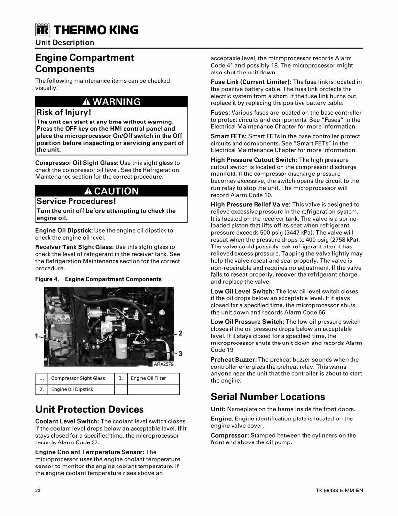
Engine CompartmentComponentsThe following maintenance items can be checkedvisually.
WWAARRNNIINNGGRRiisskk ooff IInnjjuurryy!!TThhee uunniitt ccaann ssttaarrtt aatt aannyy ttiimmee wwiitthhoouutt wwaarrnniinngg..PPrreessss tthhee OOFFFF kkeeyy oonn tthhee HHMMII ccoonnttrrooll ppaanneell aannddppllaaccee tthhee mmiiccrroopprroocceessssoorr OOnn//OOffff sswwiittcchh iinn tthhee OOffffppoossiittiioonn bbeeffoorree iinnssppeeccttiinngg oorr sseerrvviicciinngg aannyy ppaarrtt oofftthhee uunniitt..
CCoommpprreessssoorr OOiill SSiigghhtt GGllaassss:: Use this sight glass tocheck the compressor oil level. See the RefrigerationMaintenance section for the correct procedure.
CCAAUUTTIIOONNSSeerrvviiccee PPrroocceedduurreess!!TTuurrnn tthhee uunniitt ooffff bbeeffoorree aatttteemmppttiinngg ttoo cchheecckk tthheeeennggiinnee ooiill..
EEnnggiinnee OOiill DDiippssttiicckk:: Use the engine oil dipstick tocheck the engine oil level.
RReecceeiivveerr TTaannkk SSiigghhtt GGllaassss:: Use this sight glass tocheck the level of refrigerant in the receiver tank. Seethe Refrigeration Maintenance section for the correctprocedure.
Figure 4. Engine Compartment Components
1. Compressor Sight Glass 3. Engine Oil Filter
2. Engine Oil Dipstick
Unit Protection DevicesCCoooollaanntt LLeevveell SSwwiittcchh:: The coolant level switch closesif the coolant level drops below an acceptable level. If itstays closed for a specified time, the microprocessorrecords Alarm Code 37.
EEnnggiinnee CCoooollaanntt TTeemmppeerraattuurree SSeennssoorr:: Themicroprocessor uses the engine coolant temperaturesensor to monitor the engine coolant temperature. Ifthe engine coolant temperature rises above an
acceptable level, the microprocessor records AlarmCode 41 and possibly 18. The microprocessor mightalso shut the unit down.
FFuussee LLiinnkk ((CCuurrrreenntt LLiimmiitteerr)):: The fuse link is located inthe positive battery cable. The fuse link protects theelectric system from a short. If the fuse link burns out,replace it by replacing the positive battery cable.
FFuusseess:: Various fuses are located on the base controllerto protect circuits and components. See “Fuses” in theElectrical Maintenance Chapter for more information.
SSmmaarrtt FFEETTss:: Smart FETs in the base controller protectcircuits and components. See “Smart FETs” in theElectrical Maintenance Chapter for more information.
HHiigghh PPrreessssuurree CCuuttoouutt SSwwiittcchh:: The high pressurecutout switch is located on the compressor dischargemanifold. If the compressor discharge pressurebecomes excessive, the switch opens the circuit to therun relay to stop the unit. The microprocessor willrecord Alarm Code 10.
HHiigghh PPrreessssuurree RReelliieeff VVaallvvee:: This valve is designed torelieve excessive pressure in the refrigeration system.It is located on the receiver tank. The valve is a spring-loaded piston that lifts off its seat when refrigerantpressure exceeds 500 psig (3447 kPa). The valve willreseat when the pressure drops to 400 psig (2758 kPa).The valve could possibly leak refrigerant after it hasrelieved excess pressure. Tapping the valve lightly mayhelp the valve reseat and seal properly. The valve isnon-repairable and requires no adjustment. If the valvefails to reseat properly, recover the refrigerant chargeand replace the valve.
LLooww OOiill LLeevveell SSwwiittcchh:: The low oil level switch closesif the oil drops below an acceptable level. If it staysclosed for a specified time, the microprocessor shutsthe unit down and records Alarm Code 66.
LLooww OOiill PPrreessssuurree SSwwiittcchh:: The low oil pressure switchcloses if the oil pressure drops below an acceptablelevel. If it stays closed for a specified time, themicroprocessor shuts the unit down and records AlarmCode 19.
PPrreehheeaatt BBuuzzzzeerr:: The preheat buzzer sounds when thecontroller energizes the preheat relay. This warnsanyone near the unit that the controller is about to startthe engine.
Serial Number LocationsUUnniitt:: Nameplate on the frame inside the front doors.
EEnnggiinnee:: Engine identification plate is located on theengine valve cover.
CCoommpprreessssoorr:: Stamped between the cylinders on thefront end above the oil pump.
UUnniitt DDeessccrriippttiioonn

TK 56433-5-MM-EN 23
Figure 5. Compressor Serial Number Location
1. Serial Number Location
Figure 6. Engine Serial Number Location
1. Serial Number Location
Figure 7. Unit Serial Number Location
RAJ724
1
1. On Frame In Engine Compartment
UUnniitt DDeessccrriippttiioonn

24 TK 56433-5-MM-EN
Figure 8. Laminated Serial Number Plate (LocatedWhere Shown Above)
1. Unit Serial Number
2. Unit Model
3. Bill of Material Number
UUnniitt DDeessccrriippttiioonn

TK 56433-5-MM-EN 25
Electrical MaintenanceAlternator DiagnosticProceduresGeneral InformationPoor charging performance may not be caused by abad alternator. The following conditions can causeimproper battery charging, even with a good alternator(See Service Bulletin T&T 388 for more information):
• A problem may exist in the 2A output circuit fromthe alternator to the base controller or in the 2circuit from the base controller to the battery. Checkfor an open 2 or 2A circuits, fuses FS8 and FS10 ifused, loose connections, defective battery cables,or dirty battery terminals.
• The battery must be in good condition and capableof accepting a charge. Check for a damaged battery,correct electrolyte level, and loose or corrodedconnections.
• The alternator charging output will be low if thealternator belt or pulleys are defective or the belt isnot properly adjusted. Verify the belt is not loose orcracked and the pulleys are the correct size and ingood condition.
• The excitation circuit (EXC circuit) must supplyvoltage to the excite terminal of the alternator.
• The sense circuit (2Y circuit) must supply voltage tothe sense terminal of the alternator.
• The alternator must be properly grounded.
• The unit control circuits or installed accessoriesmay be drawing excessive current.
• An overcharged battery is usually caused by adefective voltage regulator.
Alternator IdentificationThese units use Thermo King Alternators (Figure 9, p.25), which are painted black.
Figure 9. Thermo King Alternator Terminal andComponent Locations
1. B+ Terminal (PositiveOutput - 2AWire)
5. F2 Terminal (Do Not Ground)
2. B- Terminal (NegativeGround - CHWire)
6. Voltage Regulator and BrushAssembly
3. S Terminal (RegulatorSense - 2 Wire)
7. W Terminal (AC Output)
4. L Terminal (RegulatorExcite - 7K/EXC Wire)
Base Controller Fuse F4The base controller has a 300 ohm resistor and aresistor bypass fuse (F4) in the alternator excitationcircuit. The fuse and resistor are connected in paralleland are located on the base controller. Removing theresistor bypass fuse places the 300 ohm resistor in theexcitation circuit as required for Thermo Kingalternators (and Australian Bosch alternators).Installing the resistor bypass fuse removes the 300ohm resistor from the excitation circuit as required forPrestolite alternators. See the specific unit wiringdiagram for exact details.
NNoottee:: The F4 fuse must be removed from the basecontroller on units equipped with Thermo Kingalternators. The voltage regulator on the ThermoKing alternators will be damaged if the unit isturned On with the F4 fuse in place on the basecontroller.
Test Equipment for Checking Voltageand CurrentAlways use accurate test equipment such as the Fluke23 Digital Multi-Meter and the Fluke Clamp-OnAmmeter accessory when checking alternator circuitvoltage and amperage. See the table below for Thermo

26 TK 56433-5-MM-EN
King service part numbers. Verify voltages aremeasured from the designated terminal to thealternator chassis ground. All voltages are DC voltagesunless otherwise noted.
Meter Service Part Number
Fluke 23 Digital Multi-Meter 204-1079
Clamp-On Ammeter for above Meter 204-947
Alternator Load TestThermo King no longer recommends a full field test fordetermining the alternator current output. Full fieldingan alternator can cause increases in alternator outputvoltage that may damage internal alternator or unitcomponents. This damage may not be readilyapparent.
To test the alternator under load, Thermo Kingrecommends the use of a clamp-on ammeter tomonitor output current, both on initial startup andunder full unit load conditions. For example, on multi-temp units, all remote evaporators should be turnedon.
General Diagnostic and WarrantyEvaluation ProcedureComplete the following diagnostic procedures beforereplacing an alternator or the voltage regulator:
1. When testing an alternator, use accurateequipment such as a Thermo King P/N 204-1079digital multimeter and a Thermo King P/N 204-947amp clamp or equivalent.
2. Verify the drive belts and pulleys of the chargingsystem are in good condition and are adjustedproperly before testing the alternator. Verify thepulleys are the correct size. Worn belts, loose belts,and worn or improperly sized pulleys will lower theoutput of the alternator.
3. The battery must be charged and in goodcondition, the battery cable connections must beclean and tight, and the 2A, 2 (sense), and EXC(excitation) circuits must be connected properly. Allcharging circuit connections must be clean andsecure.
NNoottee:: If the unit battery is questionable, a knowngood jumper battery should be substitutedfor alternator testing.
NNoottee:: Do not perform this test with a batterycharger connected to the unit battery.
NNoottee:: All voltage readings should be taken betweenthe chassis ground on the alternator and theterminals indicated, unless stated otherwise.
NNOOTTIICCEEEEqquuiippmmeenntt DDaammaaggee!!EEnneerrggiizziinngg tthhee cciirrccuuiitt wwiitthh tthhee rreessiissttoorr bbyyppaassss ffuusseeiinnssttaalllleedd wwiillll ddaammaaggee TThheerrmmoo KKiinngg aalltteerrnnaattoorrss..TThhee rreessiissttoorr bbyyppaassss ffuussee mmuusstt bbee rreemmoovveedd ffoorrTThheerrmmoo KKiinngg aalltteerrnnaattoorrss..
4. Check that the resistor bypass fuse (F4) has beenremoved. Units with Thermo King alternators musthave the resistor bypass fuse (F4) removed.
5. Check and note the battery voltage at the batterywith the unit turned off.
6. With the unit off, check the voltage at the B+terminal on the alternator. Battery voltage must bepresent. If not, check the 2A circuit and fuse F2 ifused.
7. Disconnect the alternator harness from the voltageregulator. On Thermo King alternators, carefullypush on the spring clip to release the plug lock.
8. Turn the unit on, enter the Interface Board TestMode, and energize the Alternator Excite Output.Refer to the appropriate Diagnostic Manual forinformation about the Interface Board Test Mode.
9. Check the voltage at the sense circuit (2 circuit).Battery voltage should be present. If not, check thesense circuit (2 circuit) in the alternator harness andthe main wire harness, and fuse F20 on the basecontroller.
10. Check the voltage at the excitation circuit (EXCcircuit). 10 Vdc or more should be present. If not,check the excitation circuit (EXC circuit) in thealternator harness and the unified harness.
NNoottee:: LED 18 lights up when the EXC circuit isenergized. The EXC circuit is operated by aSmart FET so during normal operation theunit must be running for the EXC circuit to beenergized.
11. Turn the unit off and reconnect the alternatorharness.
12. Attach a clamp-on ammeter around the 2A wireconnected to the B+ terminal on the alternator. Allwires connected to the B+ terminal must passthrough the clamp-on ammeter.
13. Connect a digital multi-meter between the B+terminal at the alternator and chassis ground.
14. Turn the unit on and allow it to start. Using theclamp-on ammeter, check the current flow in the 2Awire.
• A positive reading indicates the alternator ischarging. On unit startup, the current flowshould momentarily increase to allow forbattery current used during preheat andcranking. Within a short time the current shouldfall to normal unit load plus charge current tothe unit battery (typically 5-10 amps).
EElleeccttrriiccaall MMaaiinntteennaannccee

TK 56433-5-MM-EN 27
• A reading on the clamp-on ammeter at or near 0amps indicates the alternator is not charging.Checking the unit ammeter will show adischarge condition. The alternator is defectiveif there are no problems in the wiring. Recheckthe wiring before assuming the alternator isdefective.
15. Check the voltage at the B+ terminal. The voltageshould increase until it reaches the anticipatedvoltage regulator setting as shown in the tablebelow. Record the voltage.
• The voltage regulator setting varies inverselywith the temperature as shown in the tablebelow. Regulator voltage can vary fromapproximately 15.2 Vdc at -40 F (-40 C) toapproximately 13.2 Vdc at 176 F (80 C).
Tempera-ture
Anticipated RegulatorVoltage
-40 F (-40 C) From 15.2 Vdc to 14.0 Vdc
77 F (25 C) From 14.4 Vdc to 13.6 Vdc
176 F (80 C) From 14.2 Vdc to 13.2 Vdc
• If the voltage does not increase to theanticipated voltage regulator setting, thealternator is defective if there are no problemsin the wiring. Recheck the wiring beforereplacing the alternator.
16. If the voltage does increase until it reaches theanticipated voltage regulator setting, compare thevoltage at the B+ terminal to the voltage betweenthe battery terminals. The voltage at the B+ terminalshould be no more than 1.0 Vdc higher than thevoltage between the battery terminals.
a. If the voltage at the B+ terminal is no more than1.0 Vdc higher than the voltage between thebattery terminals, continue with Step 17.
b. If the voltage at the B+ (POS) terminal is morethan 1.0 Vdc higher than the voltage betweenthe battery terminals, clean and check the wiresand connections in the 2A and 2 circuits andrepeat this check.
17. Increase the charging system load as much aspossible by running the unit in high speed heat.
18. Monitor the alternator output voltage.
a. With the increased load, the alternator outputvoltage should decrease no more than 0.5 Vdc.The voltage may increase as much as 1.0 Vdc. Ifthe alternator output voltage decreases no morethan 0.5 Vdc the alternator is good.
b. If the alternator output voltage decreases morethan 0.5 Vdc, the alternator is defective if thereare no problems in the wiring. Recheck thewiring before replacing the alternator.
19. AAlltteerrnnaattoorr DDiiooddee QQuuiicckk CChheecckk::
NNoottee:: This check confirms proper diode function.
a. With the unit still running, set the digital multi-meter connected from the alternator B+ outputto chassis ground for AC volts. No more than 1.0Vac should be present. A reading of more than1.0 Vac indicates damaged alternator diodes.
20. Turn the unit off.
Field Current TestUse this test to determine if the alternator can berepaired. Perform this test with the unit turned off.
1. Attach a clamp-on ammeter to the 2A wire near theB+ terminal on the alternator.
2. Energize the field on the Thermo King alternator byconnecting a jumper wire between the F2 terminaland the B+ terminal. Do not connect the F2 terminalto ground or the alternator will be damaged.
3. Note the ammeter reading. The ammeter readingindicates the field current, which should be 2.0 to6.0 amps at 12 volts.
a. No field current or a low field current indicatesan open circuit or excessive resistance in thefield circuit. Remove the voltage regulator andbrush assembly and inspect the slip rings. If theslip rings and are acceptable, install a newvoltage regulator and brush assembly andrepeat the test. If the brushes are not theproblem, replace the alternator.
b. High field current indicates a short in the fieldcircuit. Replace the rotor or the alternator.
BatteryFiller Cap Batteries1. Inspect/clean the battery terminals and check the
electrolyte level during scheduled maintenanceinspections.
2. A dead or low battery can be the cause of anammeter indicating discharge due to lack of initialexcitation of the alternator even after the unit hasbeen boosted for starting.
3. The minimum specific gravity should be 1.235.
4. Add distilled water as necessary to maintain theproper water level.
Maintenance Free Batteries1. Inspect/clean the battery terminals and check the
electrolyte level using the integrated sight glassduring scheduled maintenance inspections.
2. A dead or low battery can be the cause of anammeter indicating discharge due to lack of initialexcitation of the alternator even after the unit hasbeen boosted for starting.
EElleeccttrriiccaall MMaaiinntteennaannccee

28 TK 56433-5-MM-EN
Battery Load Test1. Verify battery voltage of at least 12.5v before load
testing.
2. Apply 50% Cold Cranking Amps (CCA) load for 15seconds and verify minimum voltage of 9.6v.
Battery CablesThe units use 0-gauge battery cables to ensure reliablestarting in extremely cold weather. Verify the use of the0-gauge battery cables when replacing the batterycables. Refer to the unit Parts Manual for the correctpart numbers.
Base ControllerFigure 10. SR-3 Base Controller
Base Controller Fuse Size & FunctionFuse Size Function
F2 15A Power to On/Off Switch
F3 40A Power to Fuel Sol Pull-In/Starter Solenoid
F4 Noneor 2A
No fuse - all Bosch and TK alternators (SeeNote)2A fuse - all Prestolite alternators (See Note)
F5 60A Preheat Circuit (See Note)
F6 15A Power to Damper and High Speed Solenoids
Fuse Size Function
F7 2A Switch On Power to CAN Bus
F8 5A 2A power to CAN Connector J12
F9 5A 2A power to CAN Connector J14
F10 10A Power to On Relay (Right Position)Bypass HMI Control of Power (Left Position)
F11 10A Power to Auto Fresh Air Solenoid
F12 5A 2A power to CAN Connector J13
F13 2A Power to Remote Lights
F15 P/S On/Off Relay (See Note)
F20 2A Power to Alternator Sense
F25 7.5A Power to HPCO
Notes:
1. Fuse F4 must be in place for Prestolite alternators tocharge. Fuse F4 must be removed for Bosch andThermo King alternators. Service Parts BaseControllers are shipped without the F4 fuse.
2. The F5 preheat fuse is a “slow blow” type fuse. It isdesigned for use with the engine air pre-heater.Always replace the fuse with the TK specified fuse.Service Parts Base Controllers are shipped withoutthe F5 fuse.
3. The device identified as F15 is a polyswitch. Thispolyswitch provides over-current protection for theOn/Off relay. The polyswitch will reset automaticallyand is not field repairable.
Fuse F10There are three in-line fuse clips that allow for twoconfigurations of the F10 fuse. The right position is thenormal position. This position has a white bar below iton the circuit board. When fuse F10 is installed in theright position, control power is routed to the K9 On/OffRelay contacts. The On/Off keys on the HMI ControlPanel energize and de-energize the K9 On/Off Relay.When the K9 On/Off Relay is energized, power issupplied through the normally open K9 contacts to turnthe unit on.
When fuse F10 is installed in the left position, powerbypasses the K9 On/Off relay contacts and the unit willstart and run without the HMI Control Panel connected.TThhiiss ffuussee ppoossiittiioonn iiss ffoorr eemmeerrggeennccyy bbyyppaassssooppeerraattiioonn oonnllyy.. Do not operate the unit with the F10fuse installed in the left position unless absolutelynecessary.
IImmppoorrttaanntt:: If fuse F10 is installed in the left position,the unit may start and run. If the HMIControl Panel is connected and functional,the On and Off keys will still work. The Offkey will turn the unit off if fuse F10 is in theleft position, but the Base Controller willremain powered up.
EElleeccttrriiccaall MMaaiinntteennaannccee

TK 56433-5-MM-EN 29
IImmppoorrttaanntt:: If fuse F10 is installed in the left positionand the unit is turned off using the Off key,the unit will shut down but the BaseController will remain powered up. Leavingthe unit turned off in this manner for anextended period may result in a deadbattery.
Fuse F15The device identified as F15 is a poly switch. This over-current device resets automatically and is notreplaceable.
LED FunctionsThe LED is illuminated when the associated circuitoutput is energized. Not all output LEDs shown areused on single temperature trailer applications.
LED # Function LED # Function
LED 3 K2 Preheat LED 19 Liquid InjectionValve (Not Used)
LED 4 K4 Damper Solenoid LED 20 Loader Valve 3 (NotUsed)
LED 5 K3 High SpeedSolenoid
LED 21 Heartbeat (Note 1)
LED 6 K1 Run Relay LED 22 K8 Auto Fresh AirSolenoid (Optional)
LED 7 K5 Diesel/ElectricRelay
LED 23 K9 On/Off Relay
LED 8 Pilot Solenoid orCondenser InletSolenoid
LED 24 K6 Fuel SolenoidPull-In
LED 9 Receiver TankPressure Solenoid/Liquid Line Solenoid
LED 25 K7 Starter Relay
LED 10 Hot Gas Bypass/Loader Valve 2
LED 27 ETV-D (Note 2)
LED 11 Purge Valve (NotUsed)
LED 28 ETV-B (Note 2)
LED 17 Loader Valve 1 (NotUsed)
LED 29 ETV-A (Note 2)
LED 18 Alternator Excite LED 30 ETV-C (Note 2)
Notes:
1. The Status LED flashes once per second when theBase Controller is powered and operating normally.The Status LED flashes several times per secondduring a flash load. The Status LED is on withoutflashing during reboot and when the Base Controlleris under test. The Status LED flashes twice withinone second followed by one second off if a CANcommunication error is present.
2. ETV LEDs are illuminated when the respective ETVoutput is energized. On applications without ETV,the LEDs may be illuminated.
Smart FET OutputsA Smart FET is a self protecting output device used forthe functions shown in the table. Smart FETs haltcurrent flow if an over-current condition exists andgenerate an alarm. The Smart FET will resume normaloperation when the alarm is cleared and current flow iswithin limits. Smart FETs are not field repairable. Afuse is not required.
Output Function
EVA, EVB, EVC, EVD ETV Outputs
26/PS Pilot Solenoid
HG/HGS Hot Gas/Hot Gas Bypass Solenoid
LV1 Not Used
LV3 Not Used
EXC Alternator Excitation
LQI Liquid Injection Valve
LLS Not Used
GM1, GM2 Damper Gear Motor (See Note)
CIS Not Used
RTPS Not Used
PV Not Used
Note: Gear motor circuitry not present on all BaseControllers.
SMART REEFER 3 (SR-3)Microprocessor ControllerRefer to the SR-3 Trailer Single Temperature SL-400e,SLX/SLXe/SLXi Series Diagnostic Manual TK 56487 forcomplete service information about theMicroprocessor Controller and related components.
IImmppoorrttaanntt:: A ServiceWatch download can be helpfulwhen diagnosing a problem in a unit withan SR-3 Controller. Therefore, it isrecommended that a ServiceWatchdownload be preformed to help diagnose aproblem. A ServiceWatch download mustbe preformed before contacting theThermo King Service Department forassistance in diagnosing a problem. Referto the SR-3 Trailer Single Temperature SL-400e, SLX/SLXe/SLXi Series DiagnosticManual TK 56487 for information aboutdownloading the ServiceWatch DataLogger and viewing the data.
Fuse LinkThe fuse link is located in the positive battery cable.The fuse link protects the electric system from a shortin the 2 circuit. If the fuse link burns out, check for a
EElleeccttrriiccaall MMaaiinntteennaannccee

30 TK 56433-5-MM-EN
grounded 2 wire before replacing the fuse link. Replacethe fuse link by replacing the positive battery cable.
Air HeaterThe air heater is mounted on the open end of the intakemanifold. It heats the intake air to help the engine startin cold weather. The air heater is energized by themicroprocessor during preheat, just before the engineis started.
The heater is probably defective if the resistance ismore than 0.2 ohms and the current draw is less than60 amps, or if the current draw is more than 100 amps.
Check the resistance of the air intake heater with anohmmeter between the M6 terminal on the front of theheater and the screw on the back of the heater (or theheater case). The resistance should be 0.14 ± 0.02ohms.
Check the current draw of the heater with a clamp-onammeter at the H1 wire near the M6 terminal on thefront of the heater. During preheat the current drawshould be approximately 70 amps.
Figure 11. Air Heater
1. M6 Terminal
Unit WiringInspect the unit wiring and the wire harnesses duringscheduled maintenance inspections for loose, chafed,or broken wires to protect against unit malfunctionsdue to open or short circuits.
Wire Harness RoutingDo not change the factory routing of the wire harnessesinside the unit.
EElleeccttrriiccaall MMaaiinntteennaannccee

TK 56433-5-MM-EN 31
Engine MaintenanceEMI 3000EMI 3000 is an extended maintenance interval package.The EMI 3000 package consists of the following keycomponents:
• EMI 3000-Hour Cyclonic Air Cleaner Assembly andAir Cleaner Element
• EMI 3000-Hour 5-Micron Fuel Filter
• EMI 3000-Hour Dual Element Oil Filter (blue withwhite lettering)
• API Classification CJ-4 or CK-4 Oil
• Five Year or 12,000 Hour Extended Life Coolant(ELC)
The EMI package allows standard maintenanceintervals to be extended to 3,000 hours, or 2 years,whichever occurs first.
NNoottee:: Units equipped with the EMI 3000 package dorequire regular inspection in accordance withThermo King's maintenance recommendations.
NNoottee:: The new EMI 3000 oil filters and new EMI 3000air cleaners are NOT interchangeable with the oilfilters and air cleaners previously used in trailerunits.
Engine Lubrication SystemThe TK486 family of engines use a pressure lubricationsystem. Refer to the TK482 and TK486 Engine OverhaulManual (TK 50136-2-OM) for a detailed description ofthe engine lubrication system.
Engine Oil ChangeThe engine oil should be changed according to theMaintenance Inspection Schedule.
1. Drain the oil only when the engine is hot to verifythat all the oil drains out.
2. When changing oil, keep unit and trailer level so allthe oil can flow from the oil pan.
NNoottee:: It is important to get as much of the oil out aspossible because most of the dirt particles arecontained in the last few quarts of oil thatdrain out of the pan.
3. Refill the pan with oil and check the dipstick level.The new oil filter must also be filled with oil beforeit is installed, therefore use a total of approximately13 quarts (12.3 liters/litres) to fill the oil filter andrefill the pan.
4. Run the unit, and recheck the oil level.
5. The engine oil level should be at the FULL markwith the dipstick turned (threaded) into the oil pan.Never overfill.
6. See Specifications for correct type of oil.
Oil Filter ChangeThe oil filter should be changed along with the engineoil. Use a genuine Thermo King extended maintenanceoil filter.
1. Remove the filter.
2. Fill the new oil filter with clean engine oil.
3. Apply oil to the two inner O-rings of the new filterand install the filter.
4. Hand tighten the filter until it seats firmly. Theexposed dust seal ring, if equipped, does not needto be compressed.
5. Start the unit and check for leaks.
Low Oil PressureOil pressure is affected by oil temperature, oil viscosity,and engine speed.
• Low oil pressure can usually be traced to the lack ofoil, a faulty oil pressure regulating valve, or wornbearings.
• Low oil pressure is not normally caused by a faultyoil pump.
• Use the “Low Oil Pressure Flow Chart” (Figure 12,p. 32) to help diagnose low oil pressure.

32 TK 56433-5-MM-EN
Figure 12. Low Oil Pressure Flow Chart
Engine Cooling SystemThe engine employs a closed, circulating type,pressurized cooling system. Correct enginetemperatures are controlled and maintained by aradiator, fan, and thermostat. The coolant is circulatedthrough the system by a belt driven centrifugal pump.The pump draws the coolant from the side of theradiator, circulates it through the cylinder block andhead and returns it to the radiator. A thermostatmounted in the coolant outlet line from the cylinderhead to the radiator automatically maintains coolanttemperature within the specified temperature range.
All water cooled engines are shipped from the factorywith a 50 percent permanent type antifreezeconcentrate and 50 percent water mixture in the enginecooling system.
This provides the following:
1. Prevents freezing down to -30 F (-34 C).
2. Retards rust and mineral scale that can causeengine overheating.
3. Retards corrosion (acid) that can attack accumulatortanks, water tubes, radiators, and core plugs.
4. Provides lubrication for the water pump seal.
EEnnggiinnee MMaaiinntteennaannccee

TK 56433-5-MM-EN 33
Extended Life Coolant (ELC)Chevron/Delo XLC is currently the only Extended LifeCoolant approved by Thermo King for use in theseunits for five years or 12,000 hours:
NNOOTTIICCEESSyysstteemm CCoonnttaammiinnaattiioonn!!DDoo nnoott aadddd ootthheerr ttyyppeess ooff ccoooollaanntt ttoo ccoooolliinnggssyysstteemmss uussiinngg CChheevvrroonn//DDeelloo XXLLCC eexxcceepptt iinn aanneemmeerrggeennccyy.. IIff aannootthheerr ttyyppee ooff ccoooollaanntt iiss aaddddeedd,, tthheeccoooollaanntt mmuusstt bbee cchhaannggeedd ttoo CChheevvrroonn//DDeelloo XXLLCCwwhheenn aavvaaiillaabbllee..
NNoottee:: The use of 50/50 percent pre-mixed ExtendedLife Coolant (ELC) is recommended to assurethat de-ionized water is being used. If 100percent full strength concentrate is used, de-ionized or distilled water is recommended overtap water to insure the integrity of the coolingsystem is maintained.
Antifreeze Maintenance ProcedureAs with all equipment containing antifreeze, periodicinspection on a regular basis is required to verify thecondition of the antifreeze. Inhibitors become worn outand must be replaced by changing the antifreeze.Change ELC (red) engine coolant every five years or12,000 hours (whichever occurs first).
Do not mix green or blue-green engine coolant withELC (red) engine coolant. See “Extended Life Coolant(ELC)” for more information about ELC.
The factory recommends the use of a 50/50 antifreezemixture in all units even if they are not exposed tofreezing temperatures. This antifreeze mixture willprovide the required corrosion protection andlubrication for the water pump.
Checking the AntifreezeCheck the solution concentration by using atemperature compensated antifreeze hydrometer or arefractometer (P/N 204-754) designed for testingantifreeze. Maintain a minimum of 50 percentpermanent type antifreeze concentrate and 50 percentwater solution to provide protection to -30 F (-34 C). Donot mix antifreeze stronger than 68 percent permanenttype coolant concentrate and 32 percent water for usein extreme temperatures.
Changing the Antifreeze1. Run the engine until it is up to its normal operating
temperature. Stop the unit.
CCAAUUTTIIOONNRRiisskk ooff IInnjjuurryy!!AAvvooiidd ddiirreecctt ccoonnttaacctt wwiitthh hhoott ccoooollaanntt..
2. Open the engine block drain and completely drain
the coolant. Observe the coolant color. If thecoolant is dirty, proceed with steps a, b, and c.Otherwise proceed to step 3.
a. Run clear water into the radiator and allow it todrain out of the block until it is clear.
b. Close the block drain and install a commerciallyavailable radiator and block flushing agent, andoperate the unit in accordance with instructionsof the flushing agent manufacturer.
CCAAUUTTIIOONNRRiisskk ooff IInnjjuurryy!!AAvvooiidd ddiirreecctt ccoonnttaacctt wwiitthh hhoott ccoooollaanntt..
c. Open the engine block drain to drain the waterand flushing solution.
3. Run clear water into the radiator, and allow it todrain out of the block until it is clear.
4. Inspect all hoses for deterioration and hose clamptightness. Replace if necessary.
5. Loosen the water pump belt. Check the waterpump bearing for looseness.
6. Inspect the radiator cap. Replace the cap if thegasket shows any signs of deterioration.
7. If using ELC concentrate, mix one gallon of ELCconcentrate and one gallon of de-ionized or distilledwater in a container to make a 50/50 mixture (Donot add antifreeze and then water to the unit. Thisprocedure may not give a true 50/50 mixturebecause the exact cooling system capacity may notalways be known).
8. Refill the radiator with the 50/50 antifreeze mixtureand verify to bleed the air from the cooling systemas needed.
Bleeding Air from the Cooling SystemJiggle pin thermostats are original equipment on unitsthat have engines from the TK486 family of engines.Jiggle pin thermostats make it unnecessary to bleedthe air out of the engine block because they keep airfrom being trapped in the engine block. Normally, allbut about 1.5 qt (1.4 liters) of coolant drain out of thecooling system when it is drained. If approximately halfof the Cooling System Capacity (see SpecificationsChapter) seems to fill the cooling system after it hasbeen drained, air has been trapped in the block. Bleedthe air out of the block using the following procedure:
NNOOTTIICCEEEEqquuiippmmeenntt DDaammaaggee!!DDoo nnoott ssttaarrtt tthhee eennggiinnee wwiitthhoouutt bblleeeeddiinngg tthhee aaiirroouutt ooff tthhee bblloocckk..
EEnnggiinnee MMaaiinntteennaannccee

34 TK 56433-5-MM-EN
NNoottee:: If an engine runs with air trapped in the block,the engine may be damaged. The high watertemperature switch may not protect an enginethat has air trapped in the block, because thehigh water temperature switch is designed toprotect an engine from overheating due tofailures in the cooling system.
1. Remove the plug from the front end of the waterpump below the thermostat housing as shown(Figure 13, p. 34).
2. Slowly pour the coolant into the system until yousee coolant at the plug fitting.
3. Reinstall the plug.
4. Pour coolant into the system until it appears to befull.
Figure 13. Remove Plug fromWater Pump
1. Plug
5. Verify that the amount of coolant that goes backinto the system is approximately equal to theamount of coolant that came out of the system.
6. Start the engine and monitor the coolanttemperature with the unit engine coolanttemperature gauge, or by using a non-contactthermometer pointed at the thermostat housing inthe location of the high water temperature switch orsensor.
a. When the temperature reaches 150 F (66 C),shut the engine off for two minutes.
NNoottee:: This allows time for the thermostat toheat soak and open fully, ensuring thatany remaining air will be purged out ofthe engine block when the engine isrestarted.
7. Restart the engine and run it in low speed.
a. Remove the cap from the expansion tank andslowly pour coolant into expansion tank until itis full, then reinstall the expansion tank cap.
8. Repeat steps 6 and 7 until the coolant levelstabilizes.
Engine ThermostatFor the best engine operation, use a 160 F (71 C)thermostat year-round.
Coolant Level SwitchThe expansion tank uses a reed type coolant levelswitch. The coolant level switch senses the position ofthe magnetic float inside the expansion tank. When thecoolant level is above the switch, the float is in theupper position and the switch is closed. When thecoolant level is below the switch, the float is in thelower position and the switch is open.
Figure 14. Expansion Tank
1. Coolant Level Switch
Testing the Coolant Level SwitchTesting the switch in the unit is accomplished byadjusting the coolant level and also by removing theexpansion tank from the unit by flipping the tankupside down and right side up.
1. Remove the wire harness connector from thecoolant level switch.
2. Use an ohmmeter to check the continuity of theswitch at the connection pins.
3. Verify the coolant level is above the switch andcheck the continuity of the switch. The switchshould be closed. If the tank was removed from theunit, accomplish this check with the tank upsidedown.
4. Drain coolant from the expansion tank until thecoolant level is well below the switch level andcheck continuity of the switch. The switch should beopen. If the tank was removed from the unit,
EEnnggiinnee MMaaiinntteennaannccee

TK 56433-5-MM-EN 35
accomplish this check with the tank right side up.
5. Replace the switch if it is does not close in step 3and does not open in step 4.
Checking the FloatThe float is made of polypropylene foam. It is unlikelythat the float would fail unless it sticks inside the tankso it cannot move.
1. Verify the coolant level is above the float.
2. Slowly drain coolant from the expansion tank andwatch the float. The float should drop with thecoolant level.
3. If the float did not drop with the coolant level,remove the expansion tank from the unit.
4. Flip the expansion tank upside down and right sideup to see if the float moves inside the expansiontank. Replace the expansion tank with a new one ifthe float is stuck or does not move with the coolantlevel.
Replacing the Coolant Level Switch1. Disconnect the wire harness connector from the
coolant level switch.
2. Pull the coolant level switch straight up to removeit from the tank. It may be necessary to use a smallpry bar or screwdriver. Take care to avoid damageto the tank or switch.
3. Place the new coolant level switch in the tank andpress it straight down until it snaps into place.Check to make sure it is securely in place.
4. Connect the wire harness connector to the coolantlevel switch.
Engine Fuel SystemThe TK486V25X engine uses a mono-plunger anddistributor injection pump.
The components of the fuel system are:
• Fuel tank
• Fuel pre-strainer
• Inlet strainer (in fuel transfer pump)
• Priming pump
• Fuel transfer pump
• Fuel filter/water separator
• Injection pump
• Trochoid feed pump
• Injection nozzles
The priming pump is used to manually draw fuel fromthe tank up to the fuel transfer pump if the unit shouldrun out of fuel.
OperationFuel is drawn from the fuel tank and through the fuelpre-strainer and inlet strainer by the fuel transferpump. The fuel transfer pump delivers fuel to the fuelfilter/water separator. Two orifices in the filter headcontrol the pressure in the fuel system by allowing acertain amount of fuel to return to the tank. One orificeis located in the center of the filter head. It bleeds offwater. The other orifice is located off-center on the filterhead. It bleeds off air. Filtered fuel passes through aline from the outlet fitting on the filter base to theinjection pump.
The injection pump forces the fuel, at a very highpressure, through the injection nozzles. The injectionnozzles atomize the fuel as it is injected directly into thecombustion chambers.
Injection pump leakage, injection nozzle overflow andexcess fuel from the fuel filter orifice are then all sentback to the fuel tank in the return line.
Fuel Line RoutingThe fuel lines from the fuel tank connect to the fittingson the fuel filter. Do not change the factory routing ofthe fuel lines from the fuel filter to the injection pump.
MaintenanceThe injection pump and fuel transfer pump arerelatively trouble-free and if properly maintained willusually not require major service repairs betweenengine overhauls.
Contamination is the most common cause of fuelsystem problems. Therefore, to ensure best operatingresults, the fuel must be clean and fuel tanks must befree of contaminants. Change the fuel filter/waterseparator regularly, inspect/clean the fuel pre-strainer,and clean the inlet strainer on the inlet side of the fueltransfer pump.
IImmppoorrttaanntt:: Do not open the fuel system unlessrequired.
NNoottee:: The injection nozzles must be cleaned and tested(and repaired if necessary) at least every 3,000hours in accordance with EPA 40 CFR Part 89.Normal conditions are considered to be the useof clean high quality fuel, no used oil blending,and regular maintenance of the fuel systemaccording to the Maintenance InspectionSchedule. Refer to the TK482 and TK486Overhaul Manual TK 50136 for injection nozzletesting and repair procedures.
Whenever the fuel system is opened, take the followingprecautions to prevent dirt from entering the system:
• Cap all fuel lines.
• Work in a relatively clean area whenever possible.
• Complete the work in the shortest possible time.
EEnnggiinnee MMaaiinntteennaannccee

36 TK 56433-5-MM-EN
Any major injection pump or nozzle repairs should bedone by a quality diesel injection service shop. Thenecessary service equipment and facilities are notfound in most engine rebuild shops because of thelarge investment required.
The following procedures can be accomplished underfield conditions:
• Bleeding air from the fuel system.
• Fuel tank and filter systemmaintenance.
• Priming pump (hand) replacement or repair.
• Fuel transfer pump replacement or repair.
• Injection line replacement.
• Engine speed adjustments.
• Injection pump timing.
• Nozzle spray pattern testing and adjustment.
• Injection nozzle testing, adjustment, and minorrepair.
• Trochoid feed pump replacement.
Figure 15. Fuel System SLXi DRC
1. Fuel Pre-Strainer 6. Priming Pump
2. Filter Head 7. Fuel Filter/Water Separator
3. Bleed Screw 8. Return Line (To Fuel Tank)
4. Mono-plunger and Distributor Injection Pump 9. Inlet Line (From Fuel Tank)
5. Fuel Transfer Pump
EEnnggiinnee MMaaiinntteennaannccee

TK 56433-5-MM-EN 37
Fuel Return Line ReplacementThe fuel return lines (hoses) and end cap on the fuelinjection nozzles should be changed every 10,000engine operating hours. The return line kit (P/N 10-373)contains new return lines, clamps, an end cap, and adecal like the one shown below. The decal is locatednear the unit serial plate. The date and engine hoursmust be entered on the decal when the fuel return linesare changed.
Figure 16. Fuel Return Line Replacement Decal
Use the following procedure to replace the fuel returnlines and end cap.
1. Remove the clamps, the end cap, the short fuelreturn lines between the injection nozzles, and thelong fuel return line from the injection nozzle to thebanjo fitting on the injection pump.
Figure 17. Fuel Return Line Replacement
1. End Cap 4. Short Fuel Return Lines
2. Larger Clamp 5. Long Fuel Return Lines
3. Smaller Clamps
2. Discard the old clamps, end cap, and fuel returnlines.
3. Install the end cap and clamp. Note that the end caphas a larger OD than the other hoses and requires
the larger clamp.
4. Install the fuel return lines and clamps. It may benecessary to adjust the banjo fitting slightly toobtain the straightest routing for the long returnline.
5. Be sure all the fittings are tight and check for leaks.
6. Write the date and engine hours on the decal.
Bleeding the Fuel SystemIf the engine runs out of fuel, repairs are made to thefuel system, or if air gets into the system for any otherreason, the air must be bled out of the fuel system.
NNoottee:: Make sure the fuel tank vent is kept open. If thevent becomes clogged, a partial vacuumdevelops in the tank, and this increases thetendency for air to enter the system.
To bleed air from the fuel system:
1. Loosen the bleed screw about one turn.
Figure 18. Injection Pump
1. Bleed Screw
2. Priming Pump
2. Unscrew the priming pump handle and manuallyprime the fuel system until air bubbles are nolonger visible in the fuel coming out of the bleedscrew.
3. Tighten the bleed screw and screw the primingpump handle back in.
4. Loosen the injection lines at the injection nozzles.
5. Crank the engine until fuel appears at the nozzles.
6. Tighten the injection lines.
7. Start the engine and observe the engine run for a
EEnnggiinnee MMaaiinntteennaannccee

38 TK 56433-5-MM-EN
few minutes. If the engine fails to start, or starts butstops in a few minutes, repeat the procedure.
Draining Water from Fuel TankWater run through the system may damage the fuelinjection system components. Damage to the fuelinjection system will subsequently cause moreexpensive damage to the engine. A large accumulationof water in the bottom of the fuel tank will stop a dieselengine. Water should be drained during scheduledmaintenance inspections to prevent breakdowns. Drainthe water after the fuel tank and unit have remainedidle for an hour.
1. Place a container under the fuel tank to catch thedraining water and fuel.
2. Remove the drain plug from the bottom of the fueltank.
NNoottee:: Some fuel tanks have a check valve in thedrain plug fitting. Push the check valve openwith a small screwdriver to drain the tank.
3. Let the water and fuel drain into the container untilno water is visible in the fuel draining from the tank.
a. If the water and fuel do not drain freely, thevent may be plugged. If so, clean or replace thevent.
4. Install the drain plug.
Fuel Pre-StrainerThe fuel pre-strainer removes the larger contaminantparticles from the fuel before it goes through the fueltransfer pump and the fuel filter/water separator.Inspect the fuel pre-strainer during pretrip inspectionsand scheduled maintenance inspections. Remove thebowl and clean the screen if it looks dirty. Fill the bowlwith clean fuel when reinstalling the screen and bowl.
Figure 19. Fuel Pre-Strainer Components
1. Head 3. Seal
2. Screen 4. Bowl
NNoottee:: You must lubricate the seal with diesel fuel andreseat the seal fully into the groove in the bowlwhen reinstalling the screen and bowl. Properlubrication of the seal is necessary to insure anair tight seal between the pre-strainer head andthe plastic bowl.
Figure 20. Reseat Seal Fully in Groove in Bowl
1. Lubricate seal with diesel fuel and reseat seal fullyinto groove in bowl.
EEnnggiinnee MMaaiinntteennaannccee

TK 56433-5-MM-EN 39
Fuel Filter/Water SeparatorThe fuel filter/water separator filters the fuel, andremoves water from the fuel and returns it to the fueltank.
Fuel Filter/Water Separator ReplacementReplace the fuel filter/water separator at intervalsaccording to the Maintenance Inspection Schedule.
1. Unscrew the fuel filter/water separator canister witha strap wrench. Drain, and dispose of properly.
2. Clean the filter head seal surface.
3. Lubricate the canister seal with clean fuel.
4. Through one of the small openings in the top of thecanister, fill the new fuel filter/water separatorcanister with clean fuel. This will purge the air fromthe canister. Do not fill canister through the centerhole.
Figure 21. Filling Fuel Filter/Water Separator
1. Fill Through Small Openings
2. Do Not Fill Through Center Hole
5. Screw the new canister on hand-tight. Using a strapwrench, tighten another 1/4 turn.
Engine Speed AdjustmentsWhen the diesel engine fails to maintain the correctengine speed, check the following before adjusting thespeed:
1. Check the fuel pre-strainer and the inlet strainer.Check the speed.
2. Bleed the air out of the fuel system. Check thespeed.
3. Bleed the air out of the nozzles. Check the speed.
Make the engine speed adjustments with the enginefully warmed up.
High SpeedNNoottee:: To achieve proper refrigeration system capacity
in High Speed engine operation, it is importantto ensure the engine high speed throttle is setproperly.
1. Shut the unit off.
2. Remove the ball socket from the throttle bracketball.
3. Energize the high speed solenoid by using theInterface Board Test Mode to energize the highspeed solenoid while the engine is not running.
4. Adjust the ball socket on the end of the linkage rodas necessary to make it align with the throttlebracket ball with the throttle bracket held tightagainst the high speed stop screw.
5. If alignment is not possible or there is a slight gapbetween the high speed stop screw and throttlebracket, de-energize the solenoid and shorten thelinkage by threading the ball socket in up to oneturn. Reassemble and energize the solenoid. Verifythat the throttle bracket is tight against the highspeed stop screw.
NNoottee:: The engine speed will be well above 2200RPM in light refrigeration load situations.
Figure 22. Engine Speed Adjustments
1. High Speed Solenoid 4. Throttle Bracket Ball
2. Linkage Rod 5. Low Speed AdjustmentScrew
3. High Speed StopScrew
6. Ball Socket
Low Speed1. Start the unit and use the Service Test Mode to run
the unit in Defrost. The engine should run in lowspeed.
2. Go to the Gauges Menu, select Suction Pressure,and lock it on the display.
3. Wait until the Suction Pressure rises to 40 psig (276kPa) or higher.
4. Set the low speed to 1450 ± 25 rpm.
a. Loosen the jam nut on the low speedadjustment screw (see Figure “Engine Speed
EEnnggiinnee MMaaiinntteennaannccee

40 TK 56433-5-MM-EN
Adjustments” above).
b. Adjust the low speed adjustment screw toobtain the correct speed.
c. Tighten the jam nut and recheck the speed.
5. Exit the Service Test Mode.
Injection Pump TimingUse this timing procedure when installing a newinjection pump. It is not necessary to use this timingprocedure when removing and reinstalling the originalinjection pump. In that case, align the index marks onthe injection pump and the gear case as they werebefore removing the injection pump.
1. Before removing the old injection pump, note thealignment of the index marks on the injection pumpand the gear case. The index mark on the injectionpump is usually aligned with the index mark on thegear case. If not, make a mark on gear case in linewith the index mark on the injection pump (seeFigure 25, p. 40).
Figure 23. Index Mark Location
1. Index Marks
Figure 24. Index Mark Alignment
1. Index Mark on Injection Pump
2. Index Mark on Gear Case
Figure 25. Marking Gear Case
1. Index Mark on Injection Pump
2. Existing Index Mark on Gear Case
3. Make New Mark on Gear Case If Needed
2. Clean the area with brake cleaner or somethingsimilar. Place an injection angle sticker on the gearcase so the center line on the sticker is aligned withthe index mark on the injection pump. An injectionangle sticker is provided with the new injectionpump.
Figure 26. Place Injection Angle Sticker on GearCase
1. Index Mark on Injection Pump
2. Injection Angle Sticker
Figure 27. Injection Angle Sticker
EEnnggiinnee MMaaiinntteennaannccee
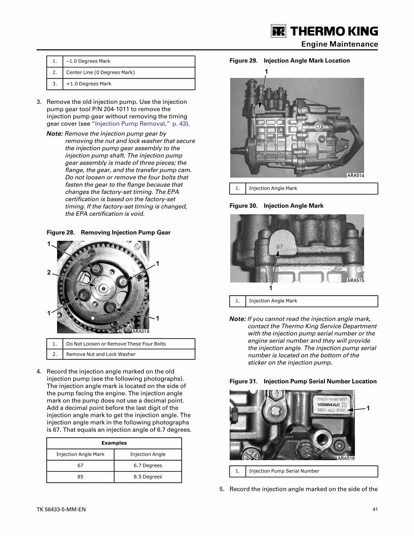
TK 56433-5-MM-EN 41
1. –1.0 Degrees Mark
2. Center Line (0 Degrees Mark)
3. +1.0 Degrees Mark
3. Remove the old injection pump. Use the injectionpump gear tool P/N 204-1011 to remove theinjection pump gear without removing the timinggear cover (see “Injection Pump Removal,” p. 43).
NNoottee:: Remove the injection pump gear byremoving the nut and lock washer that securethe injection pump gear assembly to theinjection pump shaft. The injection pumpgear assembly is made of three pieces; theflange, the gear, and the transfer pump cam.Do not loosen or remove the four bolts thatfasten the gear to the flange because thatchanges the factory-set timing. The EPAcertification is based on the factory-settiming. If the factory-set timing is changed,the EPA certification is void.
Figure 28. Removing Injection Pump Gear
1. Do Not Loosen or Remove These Four Bolts
2. Remove Nut and Lock Washer
4. Record the injection angle marked on the oldinjection pump (see the following photographs).The injection angle mark is located on the side ofthe pump facing the engine. The injection anglemark on the pump does not use a decimal point.Add a decimal point before the last digit of theinjection angle mark to get the injection angle. Theinjection angle mark in the following photographsis 67. That equals an injection angle of 6.7 degrees.
Examples
Injection Angle Mark Injection Angle
67 6.7 Degrees
85 8.5 Degrees
Figure 29. Injection Angle Mark Location
1. Injection Angle Mark
Figure 30. Injection Angle Mark
1. Injection Angle Mark
NNoottee:: If you cannot read the injection angle mark,contact the Thermo King Service Departmentwith the injection pump serial number or theengine serial number and they will providethe injection angle. The injection pump serialnumber is located on the bottom of thesticker on the injection pump.
Figure 31. Injection Pump Serial Number Location
1. Injection Pump Serial Number
5. Record the injection angle marked on the side of the
EEnnggiinnee MMaaiinntteennaannccee

42 TK 56433-5-MM-EN
new injection pump.
6. Calculate the injection angle difference bysubtracting the injection angle of the old injectionpump from the injection angle of the new injectionpump.
Examples
Injection Angle of NewInjection Pump (Degrees) 8.5 6.1
– Injection Angle of OldInjection Pump (Degrees) – 6.7 – 6.7
= Injection Angle Difference(Degrees) = +1.8 = –0.6
7. Install the new injection pump on the gear case andposition it so the index mark on the injection pumpis aligned with the mark equal to the injection angledifference on the injection angle sticker (see thefollowing examples). Tighten the injection pumpmounting nuts when the index mark is aligned asnecessary with the injection angle sticker.
Figure 32. Examples of Injection Pump Index MarkAlignment with Injection Angle Sticker
1. Injection Pump Index Mark at –0.6 Degrees
2. Injection Pump Index Mark at +1.8 Degrees
8. Install the injection pump gear, lock washer, andnut. Torque the nut to 58 to 65 ft-lb (78 to 88 N•m).
NNoottee:: If the timing gear cover was removed to removethe injection pump gear, make sure the timingmarks on the timing gears are aligned as shownbelow. It helps to install the idler gear last whenaligning the timing marks.
Figure 33. Timing Mark Alignment
1. Fuel Injection Pump Gear
2. Idler Gear
3. Camshaft Gear
4. Crankshaft Gear
NNoottee:: The oil pump is located in the timing gear coveron TK486V25/TK486V25L/TK486VHA engines.The inner rotor of the oil pump fits around thecrankshaft gear. Make sure that the flat sides ofthe inner rotor are aligned with the flat sides onthe crankshaft gear when installing the timinggear cover.
Figure 34. Align Flat Sides of Crankshaft Gear withFlat Sides of Inner Rotor in Timing Gear Cover
1. Crankshaft Gear
2. Oil Pump Cover
3. Outer Rotor
4. Inner Rotor
5. Timing Gear Cover
6. Flat Sides on Inner Rotor
7. Flat Side on Crankshaft Gear
EEnnggiinnee MMaaiinntteennaannccee

TK 56433-5-MM-EN 43
Injection Pump RemovalThe injection pump drive gear will not fit through thegear housing when removing the pump, the gear mustbe separated from the pump. Using tool P/N 204-1011,it will not be necessary to remove the belts, crankshaftpulley, crankshaft seal or front plate. See Figure 37, p.44.
1. Note the alignment of the index marks on theinjection pump and the gear case. The index markon the injection pump is usually aligned with thesingle index mark on the gear case. If not, mark it sothe injection pump can be returned to the sameposition when it is reinstalled.
Figure 35. Index Mark Location
1. Index Marks
Figure 36. Index Mark Alignment
1. Index Mark on Injection Pump
2. Index Mark on Gear Case
2. Remove the starter for clearance, remove throttlelinkage, fuel lines, harness and mounting hardwarefrom injection pump.
3. Remove the cover plate from the gear case.Remove the nut and lock washer which secure thegear to the injection pump shaft. Use a shop rag toprevent the lock washer or nut from falling into thegear case.
NNoottee:: The injection pump gear assembly is made ofthree pieces; the flange, the gear, and thetransfer pump cam. Do not loosen or removethe four bolts that fasten the gear to theflange because that changes the timing.
4. Use the hardware from the cover plate to attach thetool plate (with the marked side pointing up andout) to the gear case.
5. Align the threaded holes in the injection pump gearwith the two holes in the tool plate by rotating theengine crankshaft. Attach the gear to the tool platewith the screws provided with the tool plate.
6. Thread the long screw supplied with the tool plateinto the small end of the adapter, also supplied withthe tool plate. Insert the adapter into the tool plateand rotate to provide a solid position to force theinjection pump shaft from the gear. Caution shouldbe made to align the screw over the center of theinjection pump shaft.
7. Remove the screw and adapter leaving the toolplate in place. This holds the gear in proper toothalignment until the injection pump is re-installed.
EEnnggiinnee MMaaiinntteennaannccee

44 TK 56433-5-MM-EN
Figure 37. Injection Pump Gear Tool
1. Injection Pump 5. Adapter (Tool)
2. Gear Case 6. Tool Long Screw (Tool)
3. Cover Plate 7. Tool Short Screw (Tool)
4. Cover Plate Bolt 8. Tool Plate (Tool)
Injection Pump Reinstallation1. Position injection pump shaft into gear, rotating
shaft to mate key with keyway in gear. Take care tomake sure the key mates with the keyway.
2. Secure injection pump to gear case with previouslyremoved hardware. Make sure to align the indexmarks on the injection pump and the gear case likethey were in step 1 of “Injection PumpRemoval,” p. 43.
NNoottee:: If a different injection pump is being installed,see “Injection Pump Timing,” p. 40 to set thetiming.
3. Remove hardware holding gear to tool plate, thenremove tool plate.
4. Secure the gear to the injection pump shaft with thelock washer and nut. Use a shop rag, as before, toprevent the lock washer or nut from falling into thegear case. Torque the nut to 58 to 65 ft-lb (78 to 88N•m).
5. Fasten cover plate to gear case and reinstall allcomponents removed previously to facilitateinjection pump removal.
Fuel SolenoidThe fuel solenoid is located on the end of the injectionpump. It contains two coils: the pull-in coil, and thehold-in coil. The pull-in coil draws approximately 35 to45 amps at 12 volts. The hold-in coil drawsapproximately 0.5 amps at 12 volts.
The pull-in coil must be energized to move the injectionpump governor linkage to the fuel on position. Oncethe injection pump governor linkage has been movedto the fuel on position, the hold-in coil will keep it infuel on position until the 8D circuit is de-energized. Thepull-in coil must be de-energized after a few seconds tokeep it from being damaged. The pull-in coil iscontrolled by the microprocessor through the fuelsolenoid pull in relay (K6).
EEnnggiinnee MMaaiinntteennaannccee
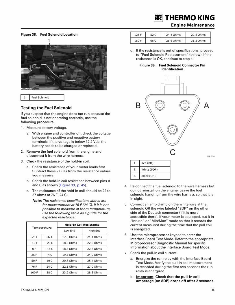
TK 56433-5-MM-EN 45
Figure 38. Fuel Solenoid Location
1. Fuel Solenoid
Testing the Fuel SolenoidIf you suspect that the engine does not run because thefuel solenoid is not operating correctly, use thefollowing procedure:
1. Measure battery voltage.
a. With engine and controller off, check the voltagebetween the positive and negative batteryterminals. If the voltage is below 12.2 Vdc, thebattery needs to be charged or replaced.
2. Remove the fuel solenoid from the engine anddisconnect it from the wire harness.
3. Check the resistance of the hold-in coil.
a. Check the resistance of your meter leads first.Subtract these values from the resistance valuesyou measure.
b. Check the hold-in coil resistance between pins Aand C as shown (Figure 39, p. 45).
c. The resistance of the hold-in coil should be 22 to27 ohms at 76 F (24 C).
NNoottee:: The resistance specifications above arefor measurement at 76 F (24 C). If it is notpossible to measure at room temperature,use the following table as a guide for theexpected resistance:
TemperatureHold-In Coil Resistance
Low End High End
-25 F -32 C 17.3 Ohms 21.1 Ohms
-10 F -23 C 18.0 Ohms 22.0 Ohms
0 F -18 C 18.5 Ohms 22.6 Ohms
25 F -4 C 19.6 Ohms 24.0 Ohms
50 F 10 C 20.8 Ohms 25.4 Ohms
76 F 24 C 22.1 Ohms 27.0 Ohms
100 F 38 C 23.2 Ohms 28.3 Ohms
125 F 52 C 24.4 Ohms 29.8 Ohms
150 F 66 C 25.6 Ohms 31.2 Ohms
d. If the resistance is out of specifications, proceedto “Fuel Solenoid Replacement” (below). If theresistance is OK, continue to step 4.
Figure 39. Fuel Solenoid Connector PinIdentification
B A
CRAJ528
1. Red (8D)
2. White (8DP)
3. Black (CH)
4. Re-connect the fuel solenoid to the wire harness butdo not reinstall on the engine. Leave the fuelsolenoid hanging from the wire harness so that it isin sight.
5. Connect an amp clamp on the white wire at thesolenoid OR the wire labeled “8DP” on the otherside of the Deutsch connector (if it is moreaccessible there). If your meter is equipped, put it in“Inrush” or “Min/Max” mode so that it records thecurrent measured during the time that the pull coilis energized.
6. Use the microprocessor keypad to enter theInterface Board Test Mode. Refer to the appropriateMicroprocessor Diagnostic Manual for specificinformation about the Interface Board Test Mode.
7. Check the pull-in coil current.
a. Energize the run relay with the Interface BoardTest Mode. Verify the pull-in coil measurementis recorded during the first two seconds the runrelay is energized.
b. IImmppoorrttaanntt:: CChheecckk tthhaatt tthhee ppuullll--iinn ccooiillaammppeerraaggee ((oonn 88DDPP)) ddrrooppss ooffff aafftteerr 22 sseeccoonnddss..
EEnnggiinnee MMaaiinntteennaannccee

46 TK 56433-5-MM-EN
IIff tthhiiss ccooiill ccoonnttiinnuueess ddrraawwiinngg ccuurrrreenntt ffoorrmmoorree tthhaann 33 sseeccoonnddss tthheerree iiss aa rreellaayy,,ccoonnttrroolllleerr,, oorr wwiirriinngg iissssuuee.. CChheecckk uunniitt rreeppaaiirrhhiissttoorryy ffoorr ssiimmiillaarr iissssuueess..
c. The current through the pull-in coil should be 26to 32 amps at 76 F (24 C).
NNoottee:: The current specifications above are formeasurement at 76 F (24 C). If it is notpossible to measure at room temperature,use the following table as a guide for theexpected current:
TemperaturePull-In Coil Current
Low End High End
-25 F -32 C 31.8 Amps 38.9 Amps
-10 F -23 C 30.8 Amps 37.7 Amps
0 F -18 C 30.4 Amps 37.2 Amps
25 F -4 C 28.7 Amps 35.0 Amps
50 F 10 C 27.2 Amps 33.2 Amps
76 F 24 C 26.0 Amps 31.8 Amps
100 F 38 C 24.9 Amps 30.4 Amps
125 F 52 C 23.3 Amps 28.4 Amps
150 F 66 C 23.3 Amps 28.5 Amps
d. If the current is out of specifications, examinethe circuit (fuses, relays, wires, etc.) for faults. Ifthe circuit is OK, proceed to “Fuel SolenoidReplacement” (below).
e. If the current is within specifications, proceed tostep 8 for a visual check.
8. Visual functionality check (no measurementsrequired).
CCAAUUTTIIOONNRRiisskk ooff IInnjjuurryy!!TThhee ffuueell ssoolleennooiidd ccaassiinngg mmaayy ggeett hhoott dduurriinnggtthhiiss rraappiidd ccyycclliinngg,, uussee ccaauuttiioonn wwhheenn hhaannddlliinngg..
a. Using the microprocessor keypad, energize thefuel solenoid circuit for 4 seconds. Turn off.Repeat ten times.
b. During each of these cycles, watch that the fuelsolenoid plunger retracts completely and staysretracted until you de-energize the circuit.
c. If the fuel solenoid plunger fails to actuate orhold during this test, check that the circuit is OK.If it appears normal, proceed to “Fuel SolenoidReplacement” (below).
Fuel Solenoid Replacement1. Disconnect the fuel solenoid wire connector from
the main/unified wire harness and remove the old
fuel solenoid.
2. Connect the new fuel solenoid wire connector tothe main/unified wire harness.
3. Press the ON Key to turn the unit on.
4. Use the microprocessor keypad to enter theInterface Board Test Mode. Refer to the appropriateMicroprocessor Diagnostic Manual for specificinformation about the Interface Board Test Mode.
5. Perform a visual functionality check per step 8 in“Testing the Fuel Solenoid” above to verify the fuelsolenoid operates correctly.
6. Energize the fuel solenoid by energizing the runrelay with the Interface Board Test Mode.
NNoottee:: The fuel solenoid must be energized when itis installed. If not, the plunger and the linkagemay not line up correctly and the fuelsolenoid will not function properly.
7. Place the O-ring in the groove in the end of the fuelinjection pump. Make sure that the O-ring ispositioned correctly during installation to avoiddamage and leaks.
Figure 40. Fuel Solenoid Components
1. Fuel Solenoid
2. O-ring
3. Groove in Fuel Injection Pump
8. Install the new fuel solenoid.
9. Press the OFF Key to turn the unit off after installingthe fuel solenoid.
Trochoid Feed PumpThe TK486V25X engine has a trochoid feed pump onthe fuel injection pump. The trochoid feed pumpsupplies fuel to the injection pump at a pressure of 65to 87 psi (450 to 600 kPa). Check the outlet pressure ofthe trochoid feed pump by removing the plug andattaching a pressure gauge to the port shown in Figure41, p. 47. The plug has M12x1.25 threads. You will haveto make an adaptor to attach a pressure gauge. Replacethe trochoid feed pump if the outlet pressure is belowthe pressure specifications in the following table.
EEnnggiinnee MMaaiinntteennaannccee

TK 56433-5-MM-EN 47
Trochoid Feed PumpOutlet Pressure
Cranking 15-30 psi (103-206 kPa)
Low Speed 30-50 psi (206-345 kPa)
High Speed 65-87 psi (450-600 kPa)
Figure 41. Trochoid Feed Pump Location
1. Trochoid Feed Pump Outlet Pressure Port
2. Trochoid Feed Pump
Trochoid Feed Pump LeaksInternal – If the seal in the trochoid feed pump fails, itcould allow some fuel to leak into the engine oil. Afaulty injection nozzle can also dilute the engine oilwith fuel. Replace the trochoid feed pump if the engineoil is being diluted with fuel and a faulty injectionnozzle or fuel transfer pump is not the cause.
External – Replace the O-ring seal between the trochoidfeed pump and the injection pump if oil is leaking.Torque the bolts to prevent leaks (6 to 7 ft-lb [8 to 10N•m]).
Replace all O-rings if fuel is leaking. Torque the Allenhead screws and Hex head bolts to prevent leaks (6 to 7ft-lb [8 to 10 N•m]).
Trochoid Feed Pump ReplacementUse the following procedure to replace the trochoidfeed pump.
1. Remove the four hex head screws that attach thetrochoid feed pump to the injection pump (seeFigure 42, p. 47). Do not remove the two Allen headscrews.
Figure 42. Trochoid Feed Pump Removal
1. Allen Head Screws (Do Not Remove)
2. Hex Head Screws
2. Remove the trochoid feed pump from the injectionpump.
NNoottee:: The gear on the trochoid feed pump islubricated with engine oil. Some engine oilmight leak out of the injection pump whenthe trochoid feed pump is removed. Thetrochoid feed pump does not need to betimed when it is installed.
3. Clean the area on the injection pump from whichthe trochoid feed pump was removed.
4. Place new O-rings on the new trochoid feed pumpand make sure it is clean.
Figure 43. Trochoid Feed Pump
1. O-Rings
5. Place the new trochoid feed pump on the injectionpump.
EEnnggiinnee MMaaiinntteennaannccee

48 TK 56433-5-MM-EN
6. Install and tighten four hex head screws that attachthe trochoid feed pump to the injection pump.Torque the hex head screws to 6 to 7 ft-lb (8 to 10N•m).
Cold Start DeviceThe TK486V25X engine has a cold start device locatedon the fuel injection pump. The cold start device has aplunger that retracts at engine coolant temperaturesbelow 41 F (5 C) to advance the injection timingapproximately 2 degrees. The plunger controls theposition of a piston in the injection pump to change thetiming. The plunger is extended and the injectiontiming is normal at engine coolant temperatures above41 F (5 C). Check the operation of the cold start device ifit is difficult to start the engine in cold weather.
NNoottee:: Do not pull the plunger out of a cold start devicebecause that will damage it.
Figure 44. Cold Start Device
1. Plunger (Extended)
Checking Cold Start Device OperationUse the following procedure to check the operation ofthe cold start device. The engine coolant temperaturemust be below 32 F (0 C) to start the procedure.
1. Press the ON Key to turn the unit on.
2. Enter the Gauges Menu before the engine startsand check the coolant temperature to make sure itis below 32 F (0 C).
3. Let the engine start, then check the engine rpm inthe Gauges Menu. The engine rpm should beapproximately 100 rpm higher than normal (seeSpecifications).
4. Let the engine run to warm up and use the GaugesMenu to check the coolant temperature and enginerpm. When the coolant temperature rises above 41F (5 C), the engine rpm should drop back to normal.Replace the cold start device if the engine rpm doesnot drop approximately 100 rpm when the enginewarms up.
Cold Start Device Replacement1. Drain the engine coolant.
2. Remove the banjo bolt that fastens the enginecoolant fitting to the cold start device. Use a backupwrench on the cold start device if necessary.
Figure 45. Remove Engine Coolant Fitting
1. Banjo Bolt
2. Engine Coolant Fitting
3. Coolant Hoses to Cold Start Device
3. Remove the cold start device from the injectionpump fitting. Use a backup wrench on the injectionpump fitting if necessary.
Figure 46. Remove Cold Start Device
1. Cold Start Device
2. Injection Pump Fitting
4. Make sure the piston inside the injection pumpfitting is clean.
EEnnggiinnee MMaaiinntteennaannccee

TK 56433-5-MM-EN 49
Figure 47. Clean Piston
1. Piston
5. Install the new cold start device with a new O-ringin the injection pump fitting. Torque the cold startdevice to 22 to 26 ft-lb (30 to 35 N•m).
6. Install the coolant fitting and banjo bolt on the coldstart device. Torque the banjo bolt to 16 to 18 ft-lb(22 to 25 N•m).
7. Refill the engine cooling system and make sure tobleed the air from the cooling system.
Engine Valve ClearanceAdjustmentThe valve clearance should be adjusted every 3,000hours.
1. Remove the rocker arm cover.
2. Remove the round cover (plug) from the timingmark access hole on the front of the bell housing.
WWAARRNNIINNGGRRiisskk ooff IInnjjuurryy!!LLoooosseenn aallll ooff tthhee iinnjjeeccttiioonn lliinneess aatt tthhee iinnjjeeccttiioonnnnoozzzzlleess ttoo pprreevveenntt tthhee ppoossssiibbiilliittyy ooff tthhee eennggiinneeffiirriinngg wwhhiillee iitt iiss bbeeiinngg rroottaatteedd..
3. Place the engine at top dead center of thecompression stroke for the number one cylinder.See steps a through d.
a. Rotate the engine in the normal direction ofrotation (clockwise viewed from the water pumpend) until the 1-4 timing mark on the flywheellines up with the index mark in the timing markaccess hole.
Figure 48. Top Dead Center One and Four
1. Index Mark
2. Top Dead Center Mark for 1 and 4
b. Check the rocker arms on the number onecylinder to see if they are loose.
c. If the rocker arms are loose, the engine is at topdead center of the compression stroke for thenumber one cylinder.
d. If the rocker arms are tight, the engine is at topdead center of the exhaust stroke for thenumber one cylinder. Rotate the engine 360degrees to place the engine at top dead centerof the compression stroke for the number onecylinder.
4. Use a feeler gauge to check the valve clearance onboth valves for the number one cylinder, the intakevalve for the number two cylinder, and the exhaustvalve for the number three cylinder. The valveclearance for both the intake valve and the exhaustvalve should be 0.006 to 0.010 in. (0.15 to 0.25 mm).
a. Check to verify that the valve stem cap is ingood condition and is positioned squarely onthe top of the valve stem. Replace the valvestem cap if it shows significant wear.
5. Adjust the valves if necessary by loosening thelocknut and turning the adjustment screw until thevalve clearance is correct.
EEnnggiinnee MMaaiinntteennaannccee
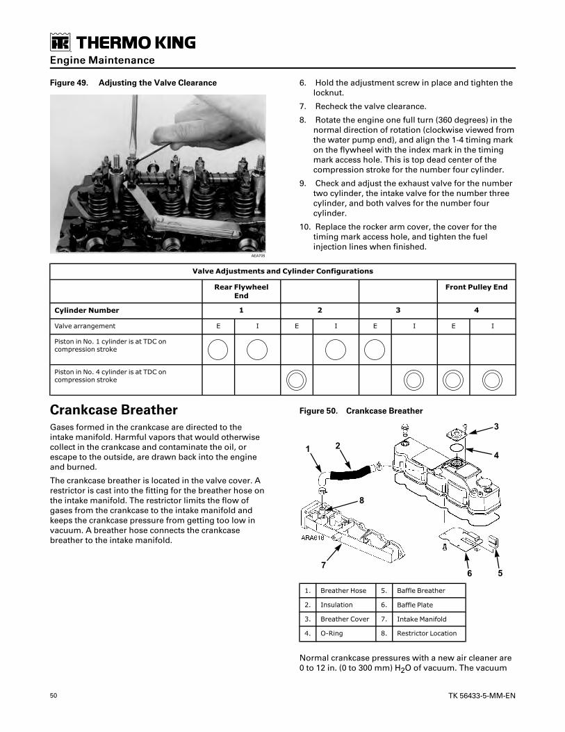
50 TK 56433-5-MM-EN
Figure 49. Adjusting the Valve Clearance 6. Hold the adjustment screw in place and tighten thelocknut.
7. Recheck the valve clearance.
8. Rotate the engine one full turn (360 degrees) in thenormal direction of rotation (clockwise viewed fromthe water pump end), and align the 1-4 timing markon the flywheel with the index mark in the timingmark access hole. This is top dead center of thecompression stroke for the number four cylinder.
9. Check and adjust the exhaust valve for the numbertwo cylinder, the intake valve for the number threecylinder, and both valves for the number fourcylinder.
10. Replace the rocker arm cover, the cover for thetiming mark access hole, and tighten the fuelinjection lines when finished.
Valve Adjustments and Cylinder Configurations
Rear FlywheelEnd
Front Pulley End
Cylinder Number 1 2 3 4
Valve arrangement E I E I E I E I
Piston in No. 1 cylinder is at TDC oncompression stroke
Piston in No. 4 cylinder is at TDC oncompression stroke
Crankcase BreatherGases formed in the crankcase are directed to theintake manifold. Harmful vapors that would otherwisecollect in the crankcase and contaminate the oil, orescape to the outside, are drawn back into the engineand burned.
The crankcase breather is located in the valve cover. Arestrictor is cast into the fitting for the breather hose onthe intake manifold. The restrictor limits the flow ofgases from the crankcase to the intake manifold andkeeps the crankcase pressure from getting too low invacuum. A breather hose connects the crankcasebreather to the intake manifold.
Figure 50. Crankcase Breather
1. Breather Hose 5. Baffle Breather
2. Insulation 6. Baffle Plate
3. Breather Cover 7. Intake Manifold
4. O-Ring 8. Restrictor Location
Normal crankcase pressures with a new air cleaner are0 to 12 in. (0 to 300 mm) H2O of vacuum. The vacuum
EEnnggiinnee MMaaiinntteennaannccee

TK 56433-5-MM-EN 51
will increase as the air cleaner gets dirty and becomesmore restrictive. Check the air restriction indicatorbefore checking the crankcase pressure. Replace the aircleaner if the reading on the air restriction indicatorexceeds 20 in. (508 mm) H2O of vacuum. A dirty aircleaner may cause excessive vacuum, leading to oilcarry over and high oil consumption.
The crankcase breather and the breather hose shouldbe inspected when the air cleaner element is replacedto verify they are not plugged or damaged. Inspect theinsulation to verify it is in place and undamaged. Theinsulation is used to prevent freezing in cold weather.
The following items can affect the crankcase pressurereadings:
CrankcasePressureEffect
Typical Cause
Increase Piston Rings Stuck or Worn
Increase Breather Hose or Restrictor Pluggedwith Dirt or Ice
Decrease Air Cleaner Dirty or Plugged
EMI 3000 Air CleanerThe EMI 3000 air cleaner is a dry element air cleaner.Replace the EMI 3000 air cleaner element at 3,000hours or 2 years, whichever occurs first.
NNoottee:: The severe duty air cleaner is similar to the EMI3000 air cleaner but allows the air cleanerelement to be replaced at 4,000 hour intervalsunder normal operating conditions.
Figure 51. EMI 3000 Air Cleaner Assembly
Figure 52. EMI 3000 Air Filter Element
BeltsBelts should be regularly inspected during unit pretripinspections for wear, scuffing, or cracking. Belt tensionshould also be checked during scheduled maintenanceinspections. Belts that are too loose will whip and beltsthat are too tight put too much strain on the belt fibersand bearings.
Using Frequency Gauge P/N 204-1903 is the bestmethod to check belt tension. Other commerciallyavailable tension gauges that measure the frequency orthe tension in pounds are also acceptable.
NNoottee:: When using the frequency gauge P/N 204-1903,place the probe near the belt with the LEDshining on the belt. Pluck the belt with a metaltab as shown below to get an accurate reading.Take three readings and average them.
Figure 53. Using Frequency Gauge P/N 204-1903
1. Probe
2. Metal Tab
NNoottee:: Do not attempt to remove or install belts withoutloosening adjustments. Belts that are installedby prying over pulleys will fail prematurely dueto internal cord damage.
EEnnggiinnee MMaaiinntteennaannccee

52 TK 56433-5-MM-EN
Fan Drive BeltFigure 54. Belt Arrangement
1. Fan Shaft 10. Fan Drive Belt Tensioner
2. Upper Condenser Blower 11. Idler Pulley
3. Condenser Inlet Orifice 12. Sliding Idler Pulley
4. Alternator 13. Cross Shaft/Fan Pulley
5. Fan Drive Belt 14. Idler Pulley
6. Alternator Pulley 15. Engine/Cross Shaft Belt Tensioner Clutch
7. Lower Condenser Blower 16. Compressor/Clutch Belt
8. Cross Shaft/Engine Pulley 17. Compressor Coupling
9. Cross Shaft (Jackshaft)
Fan Drive Belt Replacement1. Place a 17 mm socket wrench over the head of the
fan drive belt tensioner bolt in a horizontal startingposition. Slowly pull down on the tensioner untilthe belt is loose enough to remove from the
tensioner. Do not pull the tensioner down fartherthan needed to remove the belt.
EEnnggiinnee MMaaiinntteennaannccee

TK 56433-5-MM-EN 53
WWAARRNNIINNGGRRiisskk ooff IInnjjuurryy!!DDoo nnoott ppuutt ffiinnggeerrss bbeettwweeeenn tthhee bbeelltt aanndd tthheetteennssiioonneerr ppuulllleeyy..
2. Slide the belt from the tensioner pulley by hand inthe direction shown below.
Figure 55. Remove Belt from Tensioner Pulley
3. Slowly release the downward pressure on thewrench to remove it from the tensioner bolt. Thewrench will rise above the horizontal startingposition under the force of the spring.
4. Loosen (or remove) the mounting screws for theupper blower condenser spinning enough to allowthe condenser spinning to be moved away from theupper blower and the belt to be passed between theupper blower and its condenser spinning.
5. Remove the old belt.
6. Slide the new belt between the upper blower and itscondenser spinning and install the new belt on thepulleys in stages as shown below, and to tightenthe mounting screws for the upper blowercondenser spinning.
Figure 56. Stage 1
Figure 57. Stage 2
Figure 58. Stage 3
7. Ensure that the new belt is fitted correctly into thegrooves on all pulleys except the tensioner pulleyprior to beginning next step.
8. Slowly pull down on the tensioner bolt with a 17mm socket wrench and slide the new belt onto thetensioner pulley until it is correctly fitted into thegrooves of the pulley.
9. Slowly release the downward pressure on thewrench to remove it from the tensioner bolt. Thebelt should be aligned as shown below.
EEnnggiinnee MMaaiinntteennaannccee

54 TK 56433-5-MM-EN
Figure 59. Final Fan Drive Belt Alignment
10. Check the belt tension with Frequency Gauge P/N2041903. The recommended setting for a new beltis 106-118 Hz. If the tension is in this range, themark on the tensioner arm should align close to thelower mark on the tensioner housing as shownbelow. If the belt tension frequency is not in therecommended range, the sliding idler pulleyposition can be adjusted to increase/decrease belttension. See “Fan Drive Belt Adjustment” below.
NNoottee:: The belt tension frequency measurement shouldbe the primary method used to determine thecorrect belt tension. The markings on thetensioner arm and housing exist to provide arough visual reference of the belt tension.
Figure 60. Tensioner Mark Alignment
11. Monitor belt tension regularly during the run inperiod (initial 10 hours). After the belt has run in,the mark on the tensioner arm should rest betweenthe two marks on the tensioner housing.
Fan Drive Belt AdjustmentThe sliding idler pulley position is set during factoryproduction for the correct belt tension. If required, itsposition can be adjusted in the field to achieve therequired tension as follows.
NNoottee:: The distance given below is the nominal startingpoint and the exact location will depend on thevariation of the drive system layout.
1. Measure from the center of the sliding idler pulleybolt to the center of the end of the slot in the frameas shown below. The factory setting is 2.81 in. (71.5mm).
Figure 61. Sliding Idler Pulley Position
2. Perform steps 1-3 of “Fan Drive Belt Replacement”above to loosen the belt tension.
3. Loosen the sliding idler pulley bolt and adjustsliding idler position as required.
4. Tighten the sliding idler pulley bolt.
5. Perform steps 7-10 of “Fan Drive Belt Replacement”above (reset belt position and measure beltfrequency to ensure correct belt tension).
EEnnggiinnee MMaaiinntteennaannccee

TK 56433-5-MM-EN 55
Figure 62. Sliding Idler Pulley Adjustment
1. Tensioner Pulley
2. Sliding Idler Pulley – Move Forward/Backward
Engine/Cross Shaft BeltIImmppoorrttaanntt:: When replacing the compressor belt,
service tool (2042436 - Tension Tool,139mm) must be used to set the belttension, this will ensure that the correcttension is set at all times.
IImmppoorrttaanntt:: When checking the alignment of the pulleysthe service tool (2042435 - PulleyAlignment Tool) must be used to verify thecorrect positioning of theCross Shaft/Engine Pulley / Electric Motor Belt so thatalignment is maintained.
Figure 63. Engine/Cross Shaft Belt Arrangement
1. Cross Shaft/EnginePulleyCross Shaft /Electric Motor Pulley
4. Compressor Coupling
2. Engine to Motor/CrossShaft Belt
5. Tensioner Clutch
3. Back Idler Pulley
EEnnggiinnee MMaaiinntteennaannccee

56 TK 56433-5-MM-EN
Figure 64. Tensioner Clutch Components
1. Plate Adjustment Bolt 6. Grooved Idler
2. Eccentric Plate 7. Flat Idler
3. 1/2 in. Square Hole 8. Arm
4. Spring Damper Strut 9. Arm Pivot Bolt
5. Support Bracket
Assembly of Tensioner Clutch1. Remove the retainer from the arm pivot bolt.
2. Place the tensioner components on the supportbracket.
1. Eccentric Plate Pivot Bolt
2. Eccentric Plate Adjustment Bolt
3. Arm Pivot Bolt
3. Install the arm pivot bolt, and the eccentric plateadjustment and pivot bolts, and tighten them fingertight.
1. Eccentric Plate Pivot Bolt
2. Eccentric Plate Adjustment Bolt
3. Arm Pivot Bolt
4. Torque the arm pivot bolt to 106 to 114 ft-lb (144 to155 N•m). Do not tighten the eccentric plate bolts,they will be tighten when the belt is installed.
5. Install the cross shaft/engine pulley. Position pulleyaxially using block P/N 2042435 between the pulleyand the cross shaft mounting bracket. This should
place the pulley 0.65 in. (16.6 mm)from the end ofthe cross shaft housing). Tighten the pulley.
1. Cross Shaft/Engine Pulley
2. Cross Shaft Mounting Bracket
RAJ714
21
3
1. Cross Shaft / Engine Pulley
2. Cross Shaft Mounting Bracket
3. Pulley Alignment Tool 2042435
6. Install the belt following steps 10-15 of “Engine/Cross Shaft Belt Replacement” below.
Engine/Cross Shaft Belt Replacement1. Loosen the pivot bolt for the eccentric plate. The the
pivot bolt is located behind the cross shaft/enginepulley (see below).
Figure 65. Eccentric Plate Bolts
EEnnggiinnee MMaaiinntteennaannccee

TK 56433-5-MM-EN 57
1. Adjustment Bolt 2. Pivot Bolt
2. Place a 1/2 in. drive wrench in the 1/2 in. squarehole in the eccentric plate use it to hold theeccentric plate when the adjustment bolt isloosened in the next step.
3. Loosen the adjustment bolt for the eccentric plateand use the 1/2 in. drive wrench to slowly raise theeccentric plate to its highest position and releasethe belt tension.
4. Remove the belt from the cross shaft/engine pulleyand the idler pulleys.
5. Support the compressor and unbolt the compressormounting flange from the engine (leave therefrigeration lines connected).
6. Slide the compressor assembly away from theengine.
7. Remove the belt through the gap between thecompressor coupling and the flywheel.
8. Install the new belt on the compressor couplingthrough the gap between the compressor couplingand the flywheel.
9. Slide the compressor back into position and installthe mounting bolts.
10. Use use the 1/2 in. drive wrench to slowly raise theeccentric plate its highest position.
11. Place the new belt on the cross shaft/engine pulleyand idler pulleys. Verify the belt fits on the pulleyscorrectly and is fitted correctly into the grooves inthe grooved pulleys.
12. Use use the 1/2 in. drive wrench to slowly lower theeccentric plate against the belt pressure until theGauge Tool P/N 2042436 fits over the heads of thespring damper strut bolts.
IImmppoorrttaanntt:: Care must be taken when installing the beltto ensure it s correctly seated in pulleygrooves. The belt will be damaged if thecorrect installation into the pulley groovesis not observed. The belt only has to be outof place on the grooved idler by one groovefor it to fail.
IImmppoorrttaanntt:: The gauge tool must not be locked on thebolt heads but must move freely on and offthe bolt heads. The center to centerdimension of 5.472 in. (139.0 mm) betweenthe bolt heads of the spring damper strut isverified using Gauge Tool P/N 2042436,which is a checking gauge not a settinggauge and should not be used to hold thespring damper strut in position prior totightening the holding hardware.
Figure 66. Place Gauge Tool on Strut Bolts
1. Gauge Tool P/N 2042436
Figure 67. Gauge Tool on Strut Bolts
1. Gauge Tool P/N 2042436
13. Once the gauge tool fits perfectly and freely on thescrew heads of the spring damper strut, remove itand tighten the adjustment bolt and the pivot boltto lock the eccentric plate in that position.
14. Place the gauge tool over the heads of the springdamper strut bolts again to verify the setting iscorrect.
15. Remove the gauge tool and torque the strut bolts to20–24 ft-lbs (27 to 33 N•m).
EEnnggiinnee MMaaiinntteennaannccee

58 TK 56433-5-MM-EN
Water Pump BeltThe water pump pulley is a split type. Adjust thetension by adding or removing shims between thepulley sheaves. See “Belt Tension,” p. 14 for thecorrect water pump belt tension settings.
WWAARRNNIINNGGRRiisskk ooff IInnjjuurryy!!TThhee uunniitt ccaann ssttaarrtt aatt aannyy ttiimmee wwiitthhoouutt wwaarrnniinngg..PPrreessss tthhee OOFFFF kkeeyy oonn tthhee HHMMII ccoonnttrrooll ppaanneell aannddppllaaccee tthhee mmiiccrroopprroocceessssoorr OOnn//OOffff sswwiittcchh iinn tthhee OOffffppoossiittiioonn bbeeffoorree iinnssppeeccttiinngg oorr sseerrvviicciinngg aannyy ppaarrtt oofftthhee uunniitt..
CCAAUUTTIIOONNRRiisskk ooff IInnjjuurryy!!DDoo nnoott aatttteemmpptt ttoo aaddjjuusstt bbeellttss wwiitthh tthhee uunniittrruunnnniinngg..
1. Remove the bolts from the water pump pulley.
2. Remove the pulley sliding section and add orremove shims to adjust the belt tension.
3. Reinstall the belt on the pulley and replace thesliding pulley section on the pulley.
4. Tighten the mounting bolts on the water pumppulley.
5. Check the belt tension setting and readjust ifnecessary.
EEnnggiinnee MMaaiinntteennaannccee

TK 56433-5-MM-EN 59
Refrigeration MaintenanceNNoottee:: The following procedures involve servicing the
refrigeration system. Some of these serviceprocedures are regulated by Federal, and insome cases, by State and Local laws.
In the USA all regulated refrigeration serviceprocedures must be performed by an EPAcertified technician, using approved equipmentand complying with all Federal, State, and Locallaws.
Refrigerant ChargeTesting The Refrigerant Charge With AnEmpty TrailerIf the unit has an insufficient charge of refrigerant, theevaporator will be “starved” and the box temperaturewill rise even though the unit is operating. The suctionpressure will drop as the refrigerant charge decreases.If the unit has an overcharge of refrigerant, the unitmay not cool properly and the suction and dischargepressure may be high. The charge may be determinedby inspection of the refrigerant through the receivertank sight glasses with the following conditionsestablished:
1. Place a test box over the evaporator.
2. Install a gauge manifold.
3. Use the Service Test Mode to run the unit in highspeed cool. Refer to the appropriate DiagnosticManual for specific information about the ServiceTest Mode.
4. Use the microprocessor thermometer to monitorthe return air temperature.
5. Run the unit on high speed cool until the air in thebox is at 0 F (-18 C). By allowing the box to leak asmall amount, you will be able to maintain 0 F (-18C).
6. The suction pressure should be 15 to 20 psig (103 to138 kPa).
7. The discharge pressure should be at least 290 psig(2000 kPa). If the pressure is below this, it can beraised by covering a portion of the condenser grillewith a piece of cardboard to block condenserairflow.
8. Under these conditions, refrigerant should bevisible in the receiver tank sight glass. If refrigerantis not visible in the receiver tank sight glass, theunit is low on refrigerant.
Testing the Refrigerant Charge with aLoaded Trailer1. Install a gauge manifold.
2. Use the Service Test Mode to run the unit in highspeed cool. Refer to the appropriate DiagnosticManual for specific information about the ServiceTest Mode.
3. Build up and maintain 290 psig (2000 kPa) of headpressure. If the pressure is below this, it can beraised by covering the roadside condenser grillewith a piece of cardboard to block condenser airflow.
4. Cool the compartment to the lowest temperaturerequired.
5. Check suction pressure. It should be 15 to 20 psig(103 to 138 kPa).
6. Under these conditions, refrigerant should bevisible in the receiver tank sight glass. If refrigerantis not visible in the receiver tank sight glass, theunit is low on refrigerant.
Testing for an OverchargeUse the following procedure to identify a Thermo Kingunit with an excessive refrigerant charge:
1. Install a calibrated gauge manifold on thecompressor.
2. Use the Service Test Mode to run the unit in highspeed cool. Refer to the appropriate DiagnosticManual for specific information about the ServiceTest Mode.
3. Operate the unit in high speed cool long enough tostabilize system pressures and reduce the boxtemperature to approximately 60 F (16 C) or colder.
4. Observe discharge pressure and cover thecondenser to increase the discharge pressureapproximately 75 to 100 psig (500 to 690 kPa) aboveobserved pressure.
NNoottee:: If the liquid level in the receiver sight glassdrops during step 4, the unit is notovercharged and it is not necessary tocomplete the rest of the procedure.
5. Remove the condenser cover to rapidly reducedischarge pressure.
6. Observe the receiver tank sight glass and the unitdischarge pressure.
7. By the time the discharge pressure dropsapproximately 50 psig (345 kPa), the liquid level inthe receiver tank should drop.
a. When the discharge pressure stabilizes, theliquid level will rise.
b. If the liquid level will not drop, the unit mostlikely has an overcharge of refrigerant. Therefrigerant level should be adjusted.
To adjust the refrigerant level:

60 TK 56433-5-MM-EN
1. Stop the unit and remove some refrigerant with anapproved refrigerant recovery device.
2. Perform a refrigerant level check and repeat theovercharge test.
3. If the liquid level is low, add refrigerant as follows:
a. Connect a refrigerant tank to the gaugemanifold service line and purge the line.
b. Mid seat the compressor suction service valve.
c. Set the refrigerant tank for liquid removal andopen the hand valve.
d. Operate the unit in high speed cool.
e. Observe the suction pressure and slowly openthe gauge manifold low pressure hand valve toallow liquid refrigerant to flow into thecompressor suction service valve.
f. Control the liquid flow so the suction pressureincreases approximately 20 psig (138 kPa).
g. Maintain a discharge pressure of at least 290psig (2000 kPa) while adding refrigerant.
h. Close the hand valve on the refrigerant tankwhen the liquid level approaches the top of thereceiver sight glass.
4. Repeat the overcharge test.
Moisture Indicating Sight GlassThe receiver tank is equipped with a moistureindicating sight glass. The outer edge of the sight glasshas a colored ring approximately 0.1 in. (2.5 mm) thick.The color of the ring indicates the moisture content ofthe refrigerant, but it is not completely reliable.
• Green = Dry
• Chartreuse = Caution
• Yellow = Wet
Figure 68. Moisture Indicating Sight Glass
1. Floating Ball
2. Colored Ring
A system has to run for at least 15 minutes to changethe color of the indicator ring after the moisture contentof the system has been changed. For example,evacuating a system to remove the moisture will not
change the color of the indicator ring until the systemhas been recharged and then operated for at least 15minutes.
Refrigerant LeaksUse a reliable leak detector that is suitable for R-452Ato leak test the refrigeration system. Inspect for signs ofoil leakage, which is the first sign of a leak in therefrigeration system.
NNoottee:: It is normal for compressor shaft seals to have aslightly oily film.
Checking Compressor OilThe compressor oil should be checked when there isevidence of oil loss (oil leaks) or when components inthe refrigeration system have been removed for serviceor replacement.
Figure 69. Compressor Oil Sight Glass - Location
1. Sight Glass
CChheecckk CCoommpprreessssoorr OOiill LLeevveell -- AAmmbbiieenntt AAiirr TTeemmppAAbboovvee 5500 FF ((1100 CC))
1. Install a gauge manifold on the compressor.
2. Operate the unit on cool with a 20 psig (138 kPa)minimum suction pressure and a 185 psig (1275kPa) minimum discharge pressure for 15 minutes ormore.
3. After the unit has maintained the above conditionsfor 15 minutes, observe the oil level. The oil shouldbe 1/4 to 1/2 up in the sight glass.
CChheecckk CCoommpprreessssoorr OOiill LLeevveell -- AAmmbbiieenntt AAiirr TTeemmppBBeellooww 5500 FF ((1100 CC))
1. Run the unit through a complete defrost cycle.
NNoottee:: If the box is empty, you can run the unit onthe heat cycle instead of the defrost cycle.
2. After completing the defrost cycle, run the unit oncool for ten minutes.
RReeffrriiggeerraattiioonn MMaaiinntteennaannccee

TK 56433-5-MM-EN 61
3. Observe the oil level. The oil should be 1/4 to 1/2 upin the sight glass.
AAddddiinngg CCoommpprreessssoorr OOiill
NNoottee:: Use refrigeration compressor oil ONLY. PolyolEster P/N 203-513 is required for R-404A or R-452A.
1. Pump down the compressor and equalize thepressure to slightly positive.
2. Disconnect the compressor oil filter return line orremove the oil fill plug from the top of thecompressor and add the oil.
3. Reattach the oil filter return line to the compressoror reinstall the oil fill plug.
4. Evacuate the compressor before opening theservice valves.
High Pressure Cutout Switch(HPCO)The High Pressure Cutout Switch (HPCO) is located onthe compressor discharge manifold. If the dischargepressure rises above 470 psig (3241 kPa), the HPCOopens the HPCO circuit to the run relay and stops theunit. To test the HPCO, rework a gauge manifold asshown (Figure 70, p. 61) and use the followingprocedure:
1. Connect the gauge manifold to the compressordischarge service valve with a heavy duty, blackjacketed thick wall #HCA 144 hose with a 900 psig(6204 kPa) working pressure rating.
2. Use the Service Test Mode to run the unit (or hostunit) in high speed cool.
CCAAUUTTIIOONNHHaazzaarrddoouuss PPrreessssuurreess!!IIff tthhee ddiisscchhaarrggee pprreessssuurree rreeaacchheess 447777 ppssiigg ((33228899kkPPaa)),, sshhuutt tthhee uunniitt ooffff iimmmmeeddiiaatteellyy.. DDoo nnoott aalllloowwtthhee ddiisscchhaarrggee pprreessssuurree ttoo eexxcceeeedd 447777 ppssiigg ((33228899kkPPaa))..
3. Raise the discharge pressure of the compressor byblocking the condenser coil air flow by covering thecondenser grilles with pieces of cardboard. Thisshould increase the discharge pressure enough tocause the HPCO to cut out.
4. If the HPCO does not open to de-energize the runrelay and stop the unit, it must be replaced.
Figure 70. High Pressure Cutout Manifold
1. Relief Valve (66-6543)
2. O-Ring (33-1015)
3. Adapter Tee Weather Head No. 552X3
Three-Way Valve CondenserPressure Bypass Check ValveA three-way valve condenser pressure bypass checkvalve is used in this unit. This check valve controls thebypass flow of refrigerant gas between the condenserinlet line and the compressor discharge line.
The check valve is closed when the unit is running oncool, or whenever the discharge pressure is higherthan the condenser pressure.
When the unit is running on defrost or heat, if thecondenser pressure is higher than the dischargepressure, the check valve opens and the condenserpressure is bled off until it drops to the level of thedischarge pressure. The purpose of the valve is toimprove the three-way valve response time whenshifting from heat to cool.
If a three-way valve does not shift back to coolimmediately after the pilot solenoid closes, and finallyshifts to cool when the temperature rise puts the unitinto high speed, the three-way valve end cap should bechecked. See “Three-Way Valve Repair,” p. 74 inRefrigeration Service Operations.
Check the operation of the condenser pressure bypass
RReeffrriiggeerraattiioonn MMaaiinntteennaannccee

62 TK 56433-5-MM-EN
check valve as follows:
1. Remove the condenser pressure bypass checkvalve cap from the three-way valve.
2. Using a screwdriver, gently turn the check valvestem in until the valve is front seated.
3. Install a gauge manifold set on the compressor.
4. Close (front seat) the receiver tank outlet valve.
Figure 71. Three-way Valve Condenser PressureBypass Check Valve
1. Check Valve
2. Heating/Defrost Position
3. Cooling Position
5. Operate the unit on cool and pump down the lowside to 20 in. Hg (-68 kPa)of vacuum.
6. Stop the unit. The condenser and suction pressuresshould remain stable, indicating no leaks.
7. Shift the three-way valve to the heat position. Thelow side gauge will raise slightly. The high sidegauge will drop to approximately zero. The gaugeswill equalize.
8. The gauges will remain in this position,approximately zero, if the three-way valve sealsproperly toward the condenser and the condenser
pressure bypass check valve seals properly.
9. Back seat condenser pressure bypass check valvestem against the snap ring. Both gauges should riseindicating the condenser pressure bypass checkvalve is properly releasing condenser pressure intothe discharge tube and evaporator.
10. Replace the cap on the condenser pressure bypasscheck valve.
NNoottee:: Valve stem MUST be back seated duringnormal unit operation.
11. Open the receiver tank return outlet valve, removethe gauges and return the unit to normal operation.
Electronic Throttling Valve (ETV)The Electronic Throttling Valve (ETV) is standard on thethese units. The ETV is a variable position valveoperated by a stepper motor. The ETV is located in thesuction line between the accumulator and the suctionvibrasorber. The ETV system also uses discharge andsuction pressure transducers, and a hot gas bypassvalve.
The ETV has two internal coils. The microprocessoroperates the valve by energizing the coils with avariable frequency AC signal. The valve position can bemonitored with the Gauges Menu. Zero (0) indicatesthe valve is fully closed and 800 indicates the valve isfully open.
The microprocessor tests the ETV if required when theunit is started. Alarm Code 89 indicates therefrigeration system pressures did not respond asexpected during the test. This may be caused by amalfunction of the ETV or by a refrigeration systemproblem such as low refrigerant level, a frozenexpansion valve, or a restriction in suction line. Themicroprocessor ignores the test results if the boxtemperature or the ambient temperature is below 10 F(-12 C). The ETV test can also be performed using theService Test Mode.
Use the Gauges Menu to observe the ETV positionduring the ETV test. The expected ETV positionobservation is a decrease followed by an increase. Thesuction pressure should decrease when the valveposition decreases and increase when the valveposition increases.
Refer to the appropriate Diagnostic Manual forcomplete information about the testing and operationof the ETV.
Refer to “Electronic Throttling Valve” in RefrigerationService Operations for removal and installationprocedures.
RReeffrriiggeerraattiioonn MMaaiinntteennaannccee
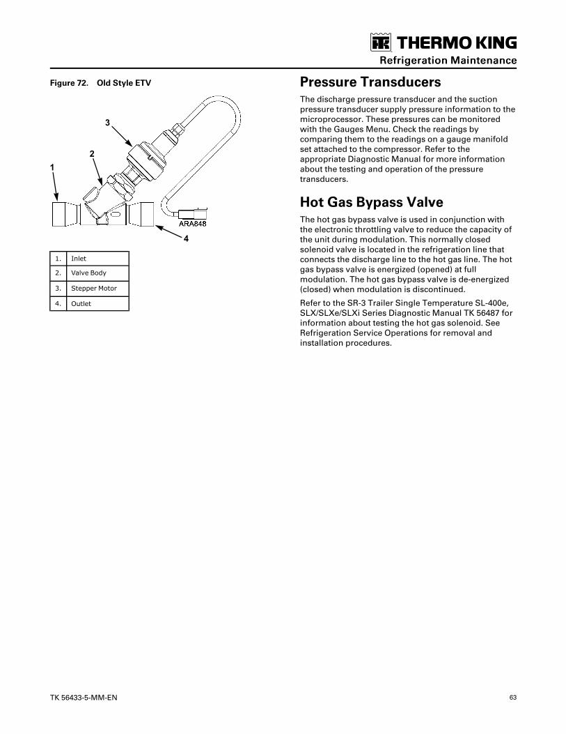
TK 56433-5-MM-EN 63
Figure 72. Old Style ETV
1. Inlet
2. Valve Body
3. Stepper Motor
4. Outlet
Pressure TransducersThe discharge pressure transducer and the suctionpressure transducer supply pressure information to themicroprocessor. These pressures can be monitoredwith the Gauges Menu. Check the readings bycomparing them to the readings on a gauge manifoldset attached to the compressor. Refer to theappropriate Diagnostic Manual for more informationabout the testing and operation of the pressuretransducers.
Hot Gas Bypass ValveThe hot gas bypass valve is used in conjunction withthe electronic throttling valve to reduce the capacity ofthe unit during modulation. This normally closedsolenoid valve is located in the refrigeration line thatconnects the discharge line to the hot gas line. The hotgas bypass valve is energized (opened) at fullmodulation. The hot gas bypass valve is de-energized(closed) when modulation is discontinued.
Refer to the SR-3 Trailer Single Temperature SL-400e,SLX/SLXe/SLXi Series Diagnostic Manual TK 56487 forinformation about testing the hot gas solenoid. SeeRefrigeration Service Operations for removal andinstallation procedures.
RReeffrriiggeerraattiioonn MMaaiinntteennaannccee

64 TK 56433-5-MM-EN
Refrigeration Service OperationsNNoottee:: The following procedures involve servicing the
refrigeration system. Some of these serviceprocedures are regulated by Federal, and insome cases, by State and Local laws.
In the USA all regulated refrigeration serviceprocedures must be performed by an EPAcertified technician, using approved equipmentand complying with all Federal, State and Locallaws.
Refrigeration SystemComponentsThe following figure shows various refrigerationsystem components.
Figure 73. Refrigeration System Components

TK 56433-5-MM-EN 65
1. Evaporator Coil 11. Suction Pressure Transducer
2. Heat Exchanger 12. Suction Vibrasorber
3. Expansion Valve 13. ETV
4. Condenser Coil 14. Accumulator
5. Discharge Pressure Transducer 15. Filter-Drier
6. Three-Way Valve 16. Receiver Tank
7. Discharge Vibrasorber 17. Condenser Check Valve
8. Hot Gas Bypass Valve 18. High Pressure Relief Valve
9. Pilot Solenoid 19. Bypass Check Valve
10. Compressor
CompressorRemoval1. Pump down the low side and equalize the pressure
to slightly positive.
2. Loosen the engine/cross shaft belt.
3. Front seat the discharge and suction service valves.
4. Recover the refrigerant remaining in thecompressor.
5. Unbolt the discharge and suction service valvesfrom the compressor.
6. Disconnect the high pressure cutout switch, thesuction pressure transducer, and the pilot solenoidline.
7. Support the compressor and unbolt thecompressor mounting flange from the engine.
8. Lift the service valves out of the way.
9. Slide the compressor to the left until the couplingpins are clear, and remove the engine/cross shaftbelt
10. Remove the compressor from the front of the unit.Keep the compressor ports covered to prevent dust,dirt, etc., from falling into the compressor.
NNoottee:: When the compressor is removed from theunit, the oil level should be noted, or the oilremoved from the compressor should bemeasured so that the same amount of oil canbe added before placing the replacementcompressor in the unit.
Installation1. Slide the compressor into the unit.
2. Place the compressor in position, install theengine/cross shaft belt, and install the mountinghardware.
NNoottee:: The compressor drive coupling will only slideonto the coupling pins in either of twopositions, which are 180 degrees apart.
3. Install the service valves using new gaskets soakedin compressor oil. Connect the high pressure cutoutswitch, the suction pressure transducer, and thepilot solenoid valve line.
4. Pressurize the compressor and test for refrigerantleaks.
5. If no leaks are found, evacuate the compressor.
6. Back seat the suction and discharge service valves.
7. Tighten the engine/cross shaft belt.
8. Operate the unit at least 30 minutes and inspect theoil level in the compressor. Add or remove oil ifnecessary.
9. Check the refrigerant charge and add refrigerant ifneeded.
Compressor Coupling Removal(Standard Units)NNoottee:: If the puller tool 2040991 is unavailable or does
not fit, a suitable commercially available pullertool can be used.
1. After the compressor has been removed from theunit, use the appropriate Allen tool provided withremoval tool P/N 2040991 to loosen the center boltwhich holds the coupling to the compressor shaft.
2. Attach the tool to the coupling with the providedsocket head screws and spacers. Two sets ofspacers are provided with the tool, use the shortspacers with shallow compressor mounting flangesand the longer set for deeper flanges. The side withthe countersunk holes should be toward thecoupling.
3. To prevent the tool and crankshaft from rotating,use an appropriately sized bolt to pin the tool to theflange. If a nut is used to prevent the bolt fromfalling out, the nut should not be tightened.
4. Use the appropriate Allen tool to loosen thecoupling mounting screw.
5. Once the center screw has been loosened, back thehead against the tool and it should push the
RReeffrriiggeerraattiioonn SSeerrvviiccee OOppeerraattiioonnss
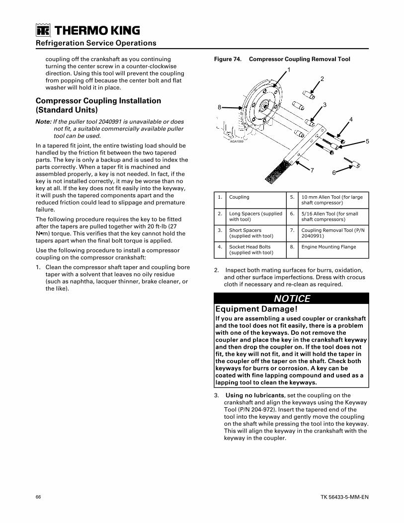
66 TK 56433-5-MM-EN
coupling off the crankshaft as you continuingturning the center screw in a counter-clockwisedirection. Using this tool will prevent the couplingfrom popping off because the center bolt and flatwasher will hold it in place.
Compressor Coupling Installation(Standard Units)NNoottee:: If the puller tool 2040991 is unavailable or does
not fit, a suitable commercially available pullertool can be used.
In a tapered fit joint, the entire twisting load should behandled by the friction fit between the two taperedparts. The key is only a backup and is used to index theparts correctly. When a taper fit is machined andassembled properly, a key is not needed. In fact, if thekey is not installed correctly, it may be worse than nokey at all. If the key does not fit easily into the keyway,it will push the tapered components apart and thereduced friction could lead to slippage and prematurefailure.
The following procedure requires the key to be fittedafter the tapers are pulled together with 20 ft-lb (27N•m) torque. This verifies that the key cannot hold thetapers apart when the final bolt torque is applied.
Use the following procedure to install a compressorcoupling on the compressor crankshaft:
1. Clean the compressor shaft taper and coupling boretaper with a solvent that leaves no oily residue(such as naphtha, lacquer thinner, brake cleaner, orthe like).
Figure 74. Compressor Coupling Removal Tool
1. Coupling 5. 10 mm Allen Tool (for largeshaft compressor)
2. Long Spacers (suppliedwith tool)
6. 5/16 Allen Tool (for smallshaft compressors)
3. Short Spacers(supplied with tool)
7. Coupling Removal Tool (P/N2040991)
4. Socket Head Bolts(supplied with tool)
8. Engine Mounting Flange
2. Inspect both mating surfaces for burrs, oxidation,and other surface imperfections. Dress with crocuscloth if necessary and re-clean as required.
NNOOTTIICCEEEEqquuiippmmeenntt DDaammaaggee!!IIff yyoouu aarree aasssseemmbblliinngg aa uusseedd ccoouupplleerr oorr ccrraannkksshhaaffttaanndd tthhee ttooooll ddooeess nnoott ffiitt eeaassiillyy,, tthheerree iiss aa pprroobblleemmwwiitthh oonnee ooff tthhee kkeeyywwaayyss.. DDoo nnoott rreemmoovvee tthheeccoouupplleerr aanndd ppllaaccee tthhee kkeeyy iinn tthhee ccrraannkksshhaafftt kkeeyywwaayyaanndd tthheenn ddrroopp tthhee ccoouupplleerr oonn.. IIff tthhee ttooooll ddooeess nnoottffiitt,, tthhee kkeeyy wwiillll nnoott ffiitt,, aanndd iitt wwiillll hhoolldd tthhee ttaappeerr iinntthhee ccoouupplleerr ooffff tthhee ttaappeerr oonn tthhee sshhaafftt.. CChheecckk bbootthhkkeeyywwaayyss ffoorr bbuurrrrss oorr ccoorrrroossiioonn.. AA kkeeyy ccaann bbeeccooaatteedd wwiitthh ffiinnee llaappppiinngg ccoommppoouunndd aanndd uusseedd aass aallaappppiinngg ttooooll ttoo cclleeaann tthhee kkeeyywwaayyss..
3. UUssiinngg nnoo lluubbrriiccaannttss, set the coupling on thecrankshaft and align the keyways using the KeywayTool (P/N 204-972). Insert the tapered end of thetool into the keyway and gently move the couplingon the shaft while pressing the tool into the keyway.This will align the keyway in the crankshaft with thekeyway in the coupler.
RReeffrriiggeerraattiioonn SSeerrvviiccee OOppeerraattiioonnss

TK 56433-5-MM-EN 67
Figure 75. Keyway Tool P/N 204–972
4. Remove the Keyway Tool and check the fit of thekey (P/N 55-9024). It should fit into the keyway witha light press fit requiring only a minimum of lighttapping. If the key does not fit properly, remove thecoupler and inspect the keyways and key for burrsor other problems. Recheck the fit as shown above.
5. When the key fits properly, remove the couplingand key from the shaft.
6. Re-install the coupling and align the keyways withthe Keyway Tool.
7. DDoo nnoott iinnssttaallll tthhee kkeeyy aatt tthhiiss ttiimmee. Install the flatwasher and bolt and pre-torque to 20 ft-lb (27 N•m).Remove the bolt and washer.
8. Install the key in the keyway. As above, it should fitwith a light press fit requiring only a minimum oflight tapping. DDoo nnoott iinnssttaallll tthhee kkeeyy iinnttoo tthheekkeeyywwaayy bbeeyyoonndd tthhee ffrroonntt ffaaccee ooff tthhee ccoouupplliinngg. Iftapped in farther, it may cause the coupling tomove off center on the shaft.
Figure 76. Compressor Coupling Installation
1. Compressor Coupling or Clutch
2. Key tapped flush with outside face of coupling. Do not tapkey any farther into keyway.
3. Torque bolt to 90 ft-lb (122 N•m)
4. Washer
5. Spray this area with corrosion inhibitor after assembling.
9. Re-install the bolt and heavy flat washer and snugthe bolt down by hand. Torque the bolt to 90 ft-lb(122 N•m).
10. Spray a corrosion inhibitor (such as spray paint) onthe exposed part of the shaft and the joint betweenthe shaft and the coupling. This prevents moisturefrom wicking into the joint and causing corrosion.
Compressors with PressurizedSeal CavityStarting in the first quarter of 2017, the pressurized sealcavity was phased into use on large shaft four cylindercompressors. Compressors with a pressurized sealcavity can be identified by the “P” on the seal cover asshown (Figure 77, p. 67). The model number of thecompressor has been changed to X430P to signify thePressurized Seal Cavity as shown (Figure 78, p. 68).The pressurized seal cavity uses a new compressorseal with a hex drive and a new crankshaft with a hexdrive collar. See “Hex Drive Compressor SealReplacement,” p. 68 for the replacement procedure.
Figure 77. Seal Cover for Compressor withPressurized Seal Cavity
1. “P” Indicates Pressurized Seal Cavity
RReeffrriiggeerraattiioonn SSeerrvviiccee OOppeerraattiioonnss

68 TK 56433-5-MM-EN
Figure 78. Model Number Location
1. “X430P” Indicates Pressurized Seal Cavity
Hex Drive Compressor SealReplacement1. Remove the compressor from the unit.
2. Remove the six mounting flange bolts and removethe mounting flange.
3. Remove the three seal plate bolts and use a slidehammer to remove the seal plate.
NNoottee:: Use slide hammer P/N 204-638 and adapter P/N 204-640 to obtain the 5/16-18 male threadneeded to fit the seal plate.
4. Place the seal plate gasket side down on a workbench and push the hard ring out of the seal plate.
NNoottee:: Provide a clean soft surface for hard ring tofall onto when pushed out of the seal plate.
5. Remove the small lip seal from the seal plate, butdo not remove the larger, internal lip seal unless itis damaged.
6. Remove the bellows assembly from the shaft byprying evenly on each side with small pry bar.
7. Retain all old seal parts for warranty return ifrequired.
8. Clean all parts thoroughly to remove all oil andgaskets.
9. Polish the crankshaft with crocus cloth if it is rustedor dirty. Do not allow abrasives to contaminate thecompressor.
10. Install the new lip seal in the seal plate with the lipside facing out and the flat side facing toward thecompressor.
Figure 79. Lip Seal Installation
1. Lip Side Facing Out
2. Flat Side Toward Compressor
NNOOTTIICCEEEEqquuiippmmeenntt DDaammaaggee!!DDOO NNOOTT ttoouucchh oorr ddaammaaggee tthhee ppoolliisshheedd sseeaall ffaacceessuurrffaacceess oonn tthhee hhaarrdd rriinngg.. KKeeeepp tthhee pprrootteeccttiivvee ccaappiinn ppoossiittiioonn oonn tthhee bbeelllloowwss uunnttiill ffiinnaall aasssseemmbbllyy..
11. Apply clean compressor oil to the new O-ring andinstall it in the seal plate. Apply clean compressoroil to the new hard ring. Verify the hard ringinstallation tool (P/N 204-953) is clean. Use the hardring installation tool to push the hard ring (with thepolished surface toward the installation tool) fullyinto the seal plate. Do not pinch the O-ring.
NNoottee:: If the installation tool is not available, use thepad in the new seal packaging to protect thepolished surface of the hard ring duringassembly.
Figure 80. Hard Ring Positions
1. This Side Toward Seal Plate
2. This Side Toward Compressor
RReeffrriiggeerraattiioonn SSeerrvviiccee OOppeerraattiioonnss

TK 56433-5-MM-EN 69
Figure 81. Hard Ring Installation
1. Seal Plate
2. O-ring
3. Hard Ring - Install with Polished SurfaceToward Compressor
4. Hard Ring Installation Tool P/N 204-953
5. Internal Lip Seal
12. If damaged, replace the internal lip seal by pryingthe old one out and press the new one into placewith the lip facing into the seal plate. Verify the lipseal is pressed all the way down into the seal plate.Oil the lip seal with supplied compressor oil.
NNoottee:: Do not replace the internal lip seal unless it isdamaged.
Figure 82. Internal Lip Seal Installation
1. Lip Facing Into Seal Plate
13. Apply clean compressor oil to the O-ring inside the
bellows. Slide the bellows on the crankshaft, alignthe hex drive on the bellows with the hex drivecollar, and push the bellows firmly against the hexdrive collar. Leave the protective cap in placeduring installation. If the hex drive does not slide oneasily, rotate the assembly 30 degrees.
Figure 83. Hex Drive Bellows Installation (ShownWithout Protective Cap)
1. Hex Drive Collar
2. Hex Drive
Figure 84. Hex Drive Type Bellows Seal
1. O-ring (Inside Bellows)
2. Hex Drive
3. Seal Faces
4. Hard Ring
5. O-ring (In Seal Plate)
6. Bellows
RReeffrriiggeerraattiioonn SSeerrvviiccee OOppeerraattiioonnss

70 TK 56433-5-MM-EN
NNOOTTIICCEEEEqquuiippmmeenntt DDaammaaggee!!OOiill aapppplliieedd ttoo tthhee sseeaall ffaacceess mmuusstt bbee aabbssoolluutteellyycclleeaann..
14. Remove the yellow protective cap. Clean the hardring and the primary ring (bronze ring) with thealcohol wipes found in package labeled “1”. Cleanthe polished mating surfaces of both rings with thelint free dry wipes from package number “2”. Applyclean compressor oil to the polished surfaces of theseal, the lip seals, and the seal plate gasket from thepackage number “3” before assembling.
15. Install the seal plate and gasket to the compressorbody. Do not bump the seal hard ring on the end ofthe crankshaft during assembly.
16. Install the seal plate mounting bolts and washers.Torque the seal plate bolts to 28 ft-lb (38 N•m) intwo steps using a criss-cross pattern.
17. Install the mounting flange and torque the bolts to28 ft-lb (38 N•m) in two steps using a criss-crosspattern.
18. Install the compressor in the unit.
Condenser CoilRemoval1. Recover the refrigerant charge.
2. Remove the condenser grille and belt panel.
3. Unsolder the inlet and outlet refrigeration lineconnections from the copper stub tubes on themicro-channel condenser coil. Use a heat sink onthe copper stub tubes.
IImmppoorrttaanntt:: This unit uses a micro-channelcondenser coil. Micro-channel coils aremade of aluminum but have copperstub tubes at the inlet and outletconnections. Use a heat sink on thecopper stub tubes to prevent damage tothe uniseal tape and brazed connections(and the aluminum) that attach thecopper stub tubes to the aluminummicro-channel coil. The uniseal tape isused to prevent corrosion between thecopper and aluminum.
4. Remove the condenser coil mounting bolts andremove the coil from the unit.
Figure 85. Top View of Curbside Condenser Coil
1. Copper Stub Tube
2. Uniseal Tape (Protects Brazed Connection between CopperStub Tube and Aluminum Micro-Channel Condenser Coil)
3. Aluminum Micro-Channel Condenser Coil
Installation1. Clean the fittings for soldering.
2. Place the coil in the unit and install the mountingbolts.
3. Solder the inlet and outlet refrigeration lineconnections to the copper stub tubes on the micro-channel condenser coil. Use a heat sink on thecopper stub tubes.
IImmppoorrttaanntt:: This unit uses a micro-channelcondenser coil. Micro-channel coils aremade of aluminum but have copperstub tubes at the inlet and outletconnections. Use a heat sink on thecopper stub tubes to prevent damage tothe uniseal tape and brazed connections(and the aluminum) that attach thecopper stub tubes to the aluminummicro-channel coil. The uniseal tape isused to prevent corrosion between thecopper and aluminum.
4. Pressurize the refrigeration system and test forleaks. If no leaks are found, evacuate the system.
5. Reinstall the condenser grille and belt panel..
6. Recharge the unit with proper refrigerant andcheck the compressor oil.
Discharge VibrasorberRemoval1. Recover the refrigerant charge.
NNOOTTIICCEEEEqquuiippmmeenntt DDaammaaggee!!UUssee aa hheeaatt ssiinnkk,, PP//NN 220044--558844,, oorr wwrraapp tthheevviibbrraassoorrbbeerr wwiitthh wweett rraaggss ttoo pprreevveenntt ddaammaaggiinngg tthheevviibbrraassoorrbbeerr..
2. Heat the connections on the vibrasorber until thevibrasorber can be removed.
Installation1. Prepare the vibrasorber and tubing fittings by
RReeffrriiggeerraattiioonn SSeerrvviiccee OOppeerraattiioonnss

TK 56433-5-MM-EN 71
cleaning thoroughly.
NNOOTTIICCEEEEqquuiippmmeenntt DDaammaaggee!!UUssee aa hheeaatt ssiinnkk,, PP//NN 220044--558844,, oorr wwrraapp tthheevviibbrraassoorrbbeerr wwiitthh wweett rraaggss ttoo pprreevveenntt ddaammaaggiinngg tthheevviibbrraassoorrbbeerr..
2. Solder the vibrasorber connections.
3. Pressurize the system and test for leaks. If no leaksare found, evacuate the system.
4. Charge the unit with the proper refrigerant andcheck the compressor oil level.
In-Line Condenser Check ValveThis unit uses an in-line condenser check valve. The in-line check valve is not repairable and must be replacedif it fails. A heat sink must be used on the in-line checkvalve when it is being soldered in place to preventdamage to the neoprene seal.
Figure 86. Cross Section of In-line Condenser CheckValve
1. Valve 3. Valve Seat
2. Neoprene Seal 4. Spring
Condenser Check ValveReplacementRemoval1. Recover the refrigerant charge.
2. Place a heat sink on the check valve.
3. Unsolder the lines and remove the check valve.
InstallationNNoottee:: A heat sink must be used on the in-line check
valve when it is being soldered in place toprevent damage to the neoprene seal.
1. Clean the tubes for soldering.
2. Place the check valve in position. The arrow on thevalve body indicates the direction of refrigerantflow through the valve.
3. Place a heat sink on the check valve.
4. Solder the inlet and outlet connections.
5. Pressurize the refrigeration system and test forleaks.
6. If no leaks are found, evacuate the system.
7. Recharge the unit with proper refrigerant andcheck the compressor oil.
Bypass Check ValveRemoval1. Pump down the low side and equalize the pressure
to slightly positive.
2. Close the bypass service valve.
3. Unsolder the bypass check valve line from thebypass check valve. Use a heat sink on the bypasscheck valve.
4. Unsolder and remove the bypass check valve fromthe receiver tank. Use a heat sink on the bypasscheck valve.
Installation1. Solder the bypass check valve onto the receiver
tank. Use a heat sink on the bypass check valve.
2. Solder the bypass check valve line to the bypasscheck valve. Use a heat sink on the bypass checkvalve.
3. Pressurize the low side and test for leaks. If noleaks are found, evacuate the system.
4. Open the suction service valve and the bypassservice valve and place the unit in operation.
Receiver TankRemoval1. Recover the refrigerant charge.
2. Unsolder the inlet, outlet, and bypass check valvelines from the receiver tank. Use a heat sink on thebypass check valve.
3. Unsolder and remove the bypass check valve fromthe receiver tank. Use a heat sink on the bypasscheck valve.
4. Remove the high pressure relief valve from thereceiver tank.
5. Unbolt the mounting brackets and remove thereceiver tank from the unit.
Installation1. Install the high pressure relief valve in the receiver
RReeffrriiggeerraattiioonn SSeerrvviiccee OOppeerraattiioonnss

72 TK 56433-5-MM-EN
tank.
2. Solder the bypass check valve onto the receivertank. Use a heat sink on the bypass check valve.
3. Place the receiver tank in the unit and install themounting bolts and nuts loosely.
4. Solder the inlet, outlet, and bypass check valvelines to the receiver tank. Use a heat sink on thebypass check valve.
5. Tighten the receiver tank mounting hardwaresecurely.
6. Pressurize the refrigeration system and check forleaks. If no leaks are found, evacuate the system.
7. Recharge the unit with proper refrigerant andcheck the compressor oil.
Filter-DrierRemoval1. Pump down the low side and equalize the pressure
to slightly positive.
2. Disconnect the nuts at the ends of the drier.
3. Loosen the mounting hardware and remove thedrier.
Installation1. Place the new O-rings in the ORS fittings on the
ends of the drier.
2. Install the new drier and tighten the mountinghardware.
3. Install and tighten the ORS nuts by holding thedrier with a back-up wrench on the hex behind theORS fitting.
4. Pressurize the low side and inspect for leaks. If noleaks are found, evacuate the low side.
5. Open the refrigeration valves and place the unit inoperation.
Expansion Valve AssemblyRemoval1. Pump down the low side and equalize the pressure
to slightly positive.
2. Remove the evaporator access panels as needed.
3. Remove the feeler bulb from the clamp. Note theposition of the feeler bulb on the suction line.
4. Unsolder the equalizer line, inlet liquid line, anddistributor from the expansion valve.
5. Remove the expansion valve mounting bolt andremove the expansion valve from the unit.
Installation1. Install and bolt the expansion valve assembly in
the unit.
2. Solder the equalizer line, inlet liquid line, anddistributor to the expansion valve.
3. Clean the suction line to a bright polishedcondition. Install the feeler bulb clamps and thefeeler bulb on the side of the suction line in itsformer position. The feeler bulb must make goodcontact with the suction line or operation will befaulty. Wrap with insulating tape.
Figure 87. Location of Expansion Valve Bulb
1. End View
2. Side View
4. Pressurize the low side and test for leaks. If noleaks are found, evacuate the low side.
5. Reinstall the access panels.
6. Open the refrigeration valves and place the unit inoperation.
7. Test the unit to see that the expansion valve isproperly installed.
Heat ExchangerRemoval1. Pump down the low side and equalize the pressure
to slightly positive.
2. Remove the evaporator access panels.
3. Remove the mounting bolts that hold the heatexchanger on the bulkhead.
4. Unsolder the equalizer line from the suction line.
5. Unsolder the liquid outlet line from the expansionvalve.
6. Note the position of the feeler bulb on the side ofthe suction line. Remove the expansion valve feeler
RReeffrriiggeerraattiioonn SSeerrvviiccee OOppeerraattiioonnss

TK 56433-5-MM-EN 73
bulb from the suction tube.
7. Unsolder the suction line at the evaporator coilend.
8. Unsolder the remaining outlet suction line and inletliquid line connections. Remove any putty fromaround the lines before unsoldering theconnections.
9. Slide the heat exchanger assembly out of theevaporator housing.
Installation1. Clean the tubes for soldering.
2. Place the heat exchanger assembly in theevaporator housing and install the mountinghardware loosely.
3. Solder the liquid inlet and the suction outlet lineconnections on the curbside of the evaporator. Sealthe openings through the bulkhead with putty whenthe refrigerant lines have cooled off.
4. Solder the suction line connection to theevaporator coil.
5. Solder the equalizer line to the suction line and theliquid outlet line to the expansion valve.
6. Tighten the heat exchanger mounting hardwaresecurely.
7. Pressurize the low side and test for leaks. If noleaks are found, evacuate the low side.
8. Clean the suction tube to a brightly polishedcondition. Install the feeler bulb clamps and thefeeler bulb on the side of the suction line in itsformer position. The feeler bulb must make goodcontact with the suction line or the operation will befaulty. Wrap with insulating tape.
9. Replace the evaporator access panels.
10. Open the refrigeration valves and place the unit inoperation.
11. Check refrigerant charge and compressor oil level
Evaporator Coil AssemblyRemoval1. Pump down the low side and equalize the pressure
to slightly positive.
2. Remove the evaporator access panels.
3. Remove the sensors.
4. Remove the heat exchanger mounting hardware.
5. Remove the feeler bulb from the suction line clamp.Note the position of the feeler bulb on the suctionline.
6. Unsolder the distributor from the expansion valve.
7. Unsolder the hot gas line and the suction line fromthe evaporator coil.
8. Remove the mounting bolts and remove the coilfrom the evaporator housing.
Installation1. Place the evaporator coil assembly in position and
install the mounting bolts.
2. Solder the hot gas line and suction line connectionsto the evaporator coil.
3. Solder the distributor to the expansion valveassembly.
4. Reinstall the heat exchanger mounting hardware.
5. Reinstall the sensors.
6. Pressurize the low side and test for leaks. If no leaksare found, evacuate the low side.
7. Clean the suction line to a bright polishedcondition. Install the feeler bulb on the side of thesuction line in its former position. The feeler bulbmust make good contact with the suction line or itsoperation will be faulty. Wrap with insulating tape.
8. Pressurize the low side and test for leaks. If no leaksare found, evacuate the low side.
9. Reinstall the evaporator access panels.
10. Open the refrigeration valves and place the unit inoperation. Check the refrigerant charge and thecompressor oil. Add as required.
AccumulatorRemoval1. Pump down the low side and equalize the pressure
to slightly positive.
NNOOTTIICCEEEEqquuiippmmeenntt DDaammaaggee!!UUssee aa hheeaatt ssiinnkk oorr wwrraapp EETTVV wwiitthh wweett rraaggss ttoopprreevveenntt ddaammaaggiinngg tthhee EETTVV..
2. Unsolder the inlet and outlet suction lines from theaccumulator.
3. Unbolt and remove the accumulator from the unit.
Installation1. Place the accumulator in the unit and tighten the
mounting bolts and nuts.
NNOOTTIICCEEEEqquuiippmmeenntt DDaammaaggee!!UUssee aa hheeaatt ssiinnkk oorr wwrraapp EETTVV wwiitthh wweett rraaggss ttoopprreevveenntt ddaammaaggiinngg tthhee EETTVV..
2. Solder the inlet and outlet suction lines to theaccumulator.
3. Pressurize the low side and test for refrigerant
RReeffrriiggeerraattiioonn SSeerrvviiccee OOppeerraattiioonnss

74 TK 56433-5-MM-EN
leaks. If no leaks are found, evacuate the low side.
4. Open the refrigeration valves and place the unit inoperation. Check the refrigerant charge and thecompressor oil. Add as required.
Three-Way Valve RepairNNoottee:: The three-way valve can be repaired in the unit if
leakage or damage to the PTFE seals shouldoccur. There is usually enough give in the coppertubing to separate the three sections of the valvewithout unsoldering any tubes.
Figure 88. Three-Way Valve
1. Cap 7. Clip
2. End Cap 8. Seat
3. Check Valve 9. Gaskets
4. Spring 10. Stem Assembly
5. Piston 11. Screen
6. Seal 12. Bottom Cap
Removal/Disassembly1. Recover the refrigerant charge.
2. Clean the exterior surface of the valve.
3. Remove the line from the three-way valve to thepilot solenoid.
NNOOTTIICCEEEEqquuiippmmeenntt DDaammaaggee!!DDoo nnoott ffoorrccee tthhee ttooooll iinnttoo tthhee bbrraassss oorr aaggaaiinnsstt tthheebboollttss..
4. Loosen the four 1/4 inch Allen head screws (DONOT REMOVE OR CAP MAY POP OFF); use tool P/N204-424 to break the gasket at each side of thecenter section.
Figure 89. Gasket Tool P/N 204-424
5. Remove the four bolts from the valve.
6. Remove the end cap and spring.
7. Remove the spring clip which secures the stem tothe piston. Slide piston off the stem.
8. Remove the seat and stem assembly.
9. Inspect the following parts for wear or damage:
• Bottom cap, sealing, and support area.
• Seat, sealing surface.
• End cap, sealing, and support surface.
The following parts will be discarded:
• Stem assembly.
• All gaskets.
• Piston seal.
10. Remove the screen. If any particles drop from thescreen into the discharge line, the discharge linemust be removed at the compressor.
NNoottee:: The valve body cannot be reconditioned.Seat positions change and improper sealingwill result.
RReeffrriiggeerraattiioonn SSeerrvviiccee OOppeerraattiioonnss

TK 56433-5-MM-EN 75
Figure 90. Piston and Stem Parts
1. Seal Groove in Piston
2. Connecting Notch in Piston
3. Internal Spring in Seal
4. Connecting Groove in Stem
5. Retaining Clip
End Cap ChecksAll end caps, even new ones, should be checked asfollows. See Service Bulletin T&T 260 for moreinformation.
Check Valve Bleed Hole Diameter1. Remove the condenser pressure bypass check
valve snap ring, stem, spring, and piston from theend cap.
2. Use a number 43 (0.089 in. [2.26 mm]) drill bit tocheck the size of the hole from the end cap gasketface to the check valve piston bore as shown.
3. If the drill does not go all the way into the bore, drillthe hole completely through.
4. Deburr the hole in the check valve piston bore. Aused drill bit can be modified to use as a deburringtool.
Figure 91. Check Bleed Hole Diameter
1. Number 43 Drill Bit
Piston Bleed Orifice Check1. Use a number 66 (0.033 in. [0.84 mm]) drill bit to
check the orifice in the bleed hole from the gasketsurface to the groove in the bottom of the pistonbore.
2. Carefully check to see that the drill projects downinto the groove and that there are no burrs at theend of the hole in the groove. Do not enlarge thishole.
Figure 92. Check Piston Bleed Orifice
1. Number 66 Drill Bit
2. Check for Burr Here
Check Valve Piston Check1. Reassemble the end cap using a new check valve
piston, spring, stem, and snap ring (Kit P/N 60-163).
2. Leave the stem back seated against the snap ring.Use a paper clip bent into a 90 degree angle to pushthe check valve piston back in its bore. Verify youcan feel the piston working against the spring.
3. With the piston pushed all the way back in its bore,use a strong light to look down the 0.089 in. (2.26mm) hole towards the back of the piston and
RReeffrriiggeerraattiioonn SSeerrvviiccee OOppeerraattiioonnss

76 TK 56433-5-MM-EN
determine how much of the end of the hole iscovered by the piston. If the piston covers morethan three-quarters of the hole replace the end cap.
NNoottee:: When front seating a condenser bypasscheck valve DO NOT over-tighten the stem.Excessive torque will deform the piston andthe deformed piston can increase the holeblockage.
Seat (Center Section) Orifice CheckThere are three 0.033 in. (0.84 mm) holes located in thethree-way valve seat (center section). Only one is useddepending on how the valve is configured.
• If the hole is too large the valve will be slow to shiftfrom heat to cool when the condenser pressure ishigher than discharge pressure because gas willflow to the discharge line instead of behind thepiston.
• If the hole is too small the valve will be slow to shiftfrom heat to cool when discharge pressure ishigher than condenser pressure because the flow isrestricted.
DDoo nnoott eennllaarrggee tthhiiss hhoollee llaarrggeerr tthhaann 00..003333 iinn.. ((00..8844mmmm))..
Whenever you disassemble a three-way valve youshould check that all three of the holes are drilledcleanly.
Figure 93. Check Seat Orifice
1. Number 66 Drill Bit
Assembly/InstallationAfter cleaning and inspecting all parts, reassemble thevalve as follows:
1. Install the screen in the bottom cap.
2. Install the new stem in the bottom cap.
3. Install new gaskets on both sides of the seat. Oilthe gaskets in compressor oil before installing.
4. Use the three-way valve seal installation tool P/N204-1008 to install a new seal on the piston. Thisprevents the seal from being stretched and
damaged.
a. Place the tapered tool over the piston.
b. Lubricate the seal with refrigeration oil.
c. Slide the seal onto the tapered tool with thespring side facing away from the piston.
d. Use the pipe to hand press the seal onto thepiston.
Figure 94. Seal Installation with Tool P/N 204-1008
1. Press by Hand 4. Tapered Tool
2. Pipe 5. Piston
3. Seal
5. Place the piston slot on the stem and secure withspring clip. The open part of the clip should be onthe opposite side of the piston slot.
6. Install the spring and end cap.
7. Line up the passageways in the cap and body.Failure to line up the holes will result in improperoperation of the valve.
8. Install the bolts and tighten in rotating sequence.Torque to 160 in-lb (18 N•m).
9. Install the pilot solenoid line and pressurize thesystem with refrigerant to check for leaks.
10. If there are no leaks, evacuate the system andrecharge with the proper refrigerant.
11. Run the unit to check for proper three-way valveoperation.
RReeffrriiggeerraattiioonn SSeerrvviiccee OOppeerraattiioonnss

TK 56433-5-MM-EN 77
Three-Way Valve CondenserPressure Bypass Check ValveRepairRemoval1. Recover the refrigerant charge.
2. Unscrew the condenser pressure bypass checkvalve cap from the three-way valve.
3. Remove the snap ring.
Figure 95. Check Valve Assembly
1. Piston 4. Stem
2. Snap Ring 5. O-ring
3. Cap 6. Spring
4. Unscrew the check valve stem by using ascrewdriver in the slot provided.
NNoottee:: The spring and piston are held in by the stem.While removing the stem, use care so thespring and piston are not lost.
5. Remove the spring and piston.
6. Inspect the check valve seat in the three-way valve.
7. If replacement parts are needed, a kit P/N 60-163must be used which includes the piston, spring, O-ring, valve stem, and snap ring.
Installation1. Coat the O-ring with compressor oil and install it
on the check valve stem.
2. Insert the spring into the hole in the check valvestem and then install the piston on the other end ofthe spring with the hole in the piston towards thespring.
NNOOTTIICCEEEEqquuiippmmeenntt DDaammaaggee!!TThhee ppiissttoonn mmuusstt bbee iinnsseerrtteedd wwiitthh tthhee ffllaatt ssiiddeeaaggaaiinnsstt tthhee vvaallvvee sseeaatt ttoo eennssuurree pprrooppeerr sseeaalliinngg..
3. Coat the entire assembly with compressor oil andinstall the assembly into the check valve seat in thethree-way valve.
4. Screw the check valve stem into the three-wayvalve until the snap ring can be installed.
5. Install the snap ring.
6. Unscrew (back seat) the check valve stem againstthe snap ring.
NNoottee:: The valve stem must be back seated duringnormal unit operation.
7. Coat the sealing area in the cap with compressoroil, install and tighten the cap on the three-wayvalve.
8. Pressurize the refrigeration system and test forleaks. If no leaks are found, evacuate the system.
9. Recharge the unit with the proper refrigerant.
Pilot SolenoidRemoval1. Recover the refrigerant charge.
2. Disconnect the wires and remove the coil from thevalve.
3. Unsolder the refrigeration lines.
4. Remove the mounting bolts and remove the valve.
Installation1. Remove the coil from the valve.
2. Place the valve in the unit and install the mountingbolts. The arrow on the valve indicates the directionof flow through the valve. Verify that the arrowpoints in the proper direction.
3. Solder the refrigeration lines to the valve.
4. Install the coil and connect the wires.
5. Pressurize the refrigeration system and test forleaks. If no leaks are found, evacuate the system.
6. Recharge the unit with the proper refrigerant andcheck the compressor oil.
Suction VibrasorberRemoval1. Pump down the low side and equalize pressure to
slightly positive.
2. Unsolder the suction vibrasorber from the suctionservice valve.
RReeffrriiggeerraattiioonn SSeerrvviiccee OOppeerraattiioonnss
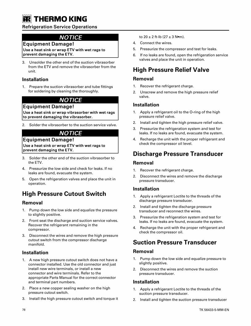
78 TK 56433-5-MM-EN
NNOOTTIICCEEEEqquuiippmmeenntt DDaammaaggee!!UUssee aa hheeaatt ssiinnkk oorr wwrraapp EETTVV wwiitthh wweett rraaggss ttoopprreevveenntt ddaammaaggiinngg tthhee EETTVV..
3. Unsolder the other end of the suction vibrasorberfrom the ETV and remove the vibrasorber from theunit.
Installation1. Prepare the suction vibrasorber and tube fittings
for soldering by cleaning the thoroughly.
NNOOTTIICCEEEEqquuiippmmeenntt DDaammaaggee!!UUssee aa hheeaatt ssiinnkk oorr wwrraapp vviibbrraassoorrbbeerr wwiitthh wweett rraaggssttoo pprreevveenntt ddaammaaggiinngg tthhee vviibbrraassoorrbbeerr..
2. Solder the vibrasorber to the suction service valve.
NNOOTTIICCEEEEqquuiippmmeenntt DDaammaaggee!!UUssee aa hheeaatt ssiinnkk oorr wwrraapp EETTVV wwiitthh wweett rraaggss ttoopprreevveenntt ddaammaaggiinngg tthhee EETTVV..
3. Solder the other end of the suction vibrasorber tothe ETV.
4. Pressurize the low side and check for leaks. If noleaks are found, evacuate the system.
5. Open the refrigeration valves and place the unit inoperation.
High Pressure Cutout SwitchRemoval1. Pump down the low side and equalize the pressure
to slightly positive.
2. Front seat the discharge and suction service valves.Recover the refrigerant remaining in thecompressor.
3. Disconnect the wires and remove the high pressurecutout switch from the compressor dischargemanifold.
Installation1. A new high pressure cutout switch does not have a
connector installed. Use the old connector and justinstall new wire terminals, or install a newconnector and wire terminals. Refer to theappropriate Parts Manual for the correct connectorand terminal part numbers.
2. Place a new copper sealing washer on the highpressure cutout switch.
3. Install the high pressure cutout switch and torque it
to 20 ± 2 ft-lb (27 ± 3 N•m).
4. Connect the wires.
5. Pressurize the compressor and test for leaks.
6. If no leaks are found, open the refrigeration servicevalves and place the unit in operation.
High Pressure Relief ValveRemoval1. Recover the refrigerant charge.
2. Unscrew and remove the high pressure reliefvalve.
Installation1. Apply a refrigerant oil to the O-ring of the high
pressure relief valve.
2. Install and tighten the high pressure relief valve.
3. Pressurize the refrigeration system and test forleaks. If no leaks are found, evacuate the system.
4. Recharge the unit with the proper refrigerant andcheck the compressor oil level.
Discharge Pressure TransducerRemoval1. Recover the refrigerant charge.
2. Disconnect the wires and remove the dischargepressure transducer.
Installation1. Apply a refrigerant Loctite to the threads of the
discharge pressure transducer.
2. Install and tighten the discharge pressuretransducer and reconnect the wires.
3. Pressurize the refrigeration system and test forleaks. If no leaks are found, evacuate the system.
4. Recharge the unit with the proper refrigerant andcheck the compressor oil.
Suction Pressure TransducerRemoval1. Pump down the low side and equalize pressure to
slightly positive.
2. Disconnect the wires and remove the suctionpressure transducer.
Installation1. Apply a refrigerant Loctite to the threads of the
suction pressure transducer.
2. Install and tighten the suction pressure transducer
RReeffrriiggeerraattiioonn SSeerrvviiccee OOppeerraattiioonnss

TK 56433-5-MM-EN 79
and reconnect the wires.
3. Pressurize the low side and check for leaks. If noleaks are found, evacuate the low side.
4. Open the refrigeration valves and place the unit inoperation.
Electronic Throttling Valve (ETV)Removal1. Pump down the low side and equalize the pressure
to slightly positive.
2. The ETV must be open to remove the stepper motorand piston assembly. Open the ETV by placing theunit in the Evacuation Mode/Test, anddisconnecting the four-pin connector on the main/unified harness from the four-pin connector on theETV before turning the unit off. The microprocessorcloses the ETV when the unit is turned off. Refer tothe appropriate Diagnostic Manual for informationabout the Evacuation Mode/Test.
Figure 96. ETV
1. Four-Pin Connector
2. Stepper Motor
3. Valve Body
CCAAUUTTIIOONNRRiisskk ooff IInnjjuurryy!!IIff tthhee EETTVV iiss ssttuucckk iinn tthhee cclloosseedd ppoossiittiioonn,, mmuucchh oofftthhee rreeffrriiggeerraanntt cchhaarrggee mmaayy bbee ttrraappppeedd iinn tthheeeevvaappoorraattoorr aanndd aaccccuummuullaattoorr.. IIff yyoouu hheeaarrrreeffrriiggeerraanntt bbeeggiinn ttoo ffllooww tthhrroouugghh tthhee vvaallvvee wwhheenntthhee sstteeppppeerr mmoottoorr aanndd ppiissttoonn aasssseemmbbllyy aarreelloooosseenneedd,, uunnssccrreeww tthhee ffoouurr ssccrreewwss oonn tthhee sstteeppppeerrmmoottoorr nnoo mmoorree tthhaann ffoouurr ttuurrnnss eeaacchh aanndd cchheecckk tthheessuuccttiioonn ((llooww ssiiddee)) pprreessssuurree oonn tthhee ggaauuggee mmaanniiffoolldd..IIff tthhee ssuuccttiioonn pprreessssuurree hhaass iinnccrreeaasseedd ffrroomm tthheepprreessssuurree ttoo wwhhiicchh iitt wwaass eeqquuaalliizzeedd aafftteerr tthhee lloowwssiiddee ppuummpp ddoowwnn,, rreeffrriiggeerraanntt iiss ttrraappppeedd aanndd mmuussttbbee rreeccoovveerreedd.. SSccrreeww tthhee sstteeppppeerr mmoottoorr aanndd ppiissttoonnaasssseemmbbllyy bbaacckk iinnttoo tthhee vvaallvvee bbooddyy.. AAttttaacchh aarreeffrriiggeerraanntt rreeccoovveerryy ddeevviiccee ttoo tthhee sseerrvviiccee ppoorrtt oonntthhee rreecceeiivveerr ttaannkk oouuttlleett vvaallvvee.. MMiiddsseeaatt tthhee rreecceeiivveerrttaannkk oouuttlleett vvaallvvee,, aanndd rreeccoovveerr tthhee rreeffrriiggeerraannttcchhaarrggee.. TThhee sstteeppppeerr mmoottoorr aanndd ppiissttoonn aasssseemmbbllyymmaayy tthheenn bbee rreemmoovveedd..
3. Remove the four screws that attach the steppermotor to the valve body.
Figure 97. Removing Stepper Motor
1. Remove Four Screws
4. If the complete ETV assembly is being replaced,unsolder and remove the valve body. It may benecessary to unsolder the tubes above or below thevalve body to obtain enough clearance to removethe valve body. Note the position of the valve bodyso the new one will be placed in the same position.The new ETV could interfere with othercomponents if it is not placed in the same positionas the old one.
RReeffrriiggeerraattiioonn SSeerrvviiccee OOppeerraattiioonnss
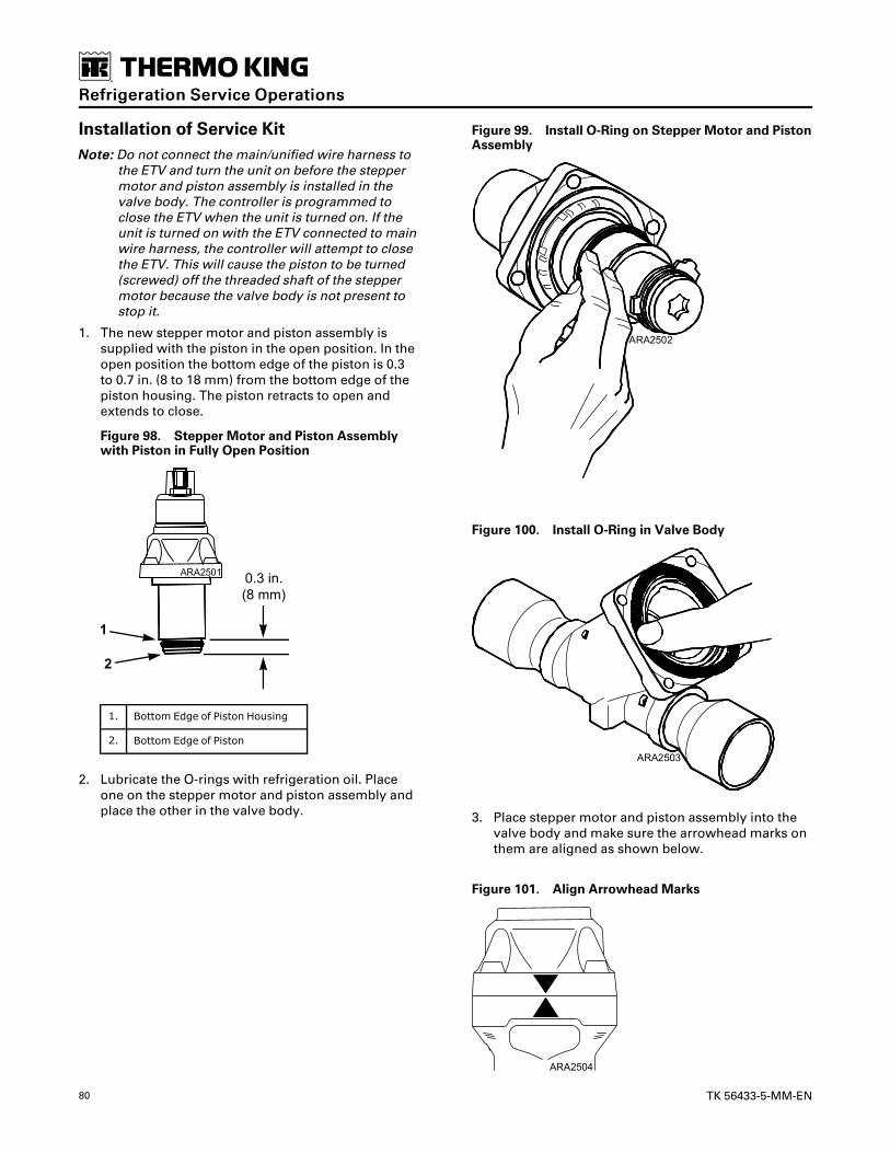
80 TK 56433-5-MM-EN
Installation of Service KitNNoottee:: Do not connect the main/unified wire harness to
the ETV and turn the unit on before the steppermotor and piston assembly is installed in thevalve body. The controller is programmed toclose the ETV when the unit is turned on. If theunit is turned on with the ETV connected to mainwire harness, the controller will attempt to closethe ETV. This will cause the piston to be turned(screwed) off the threaded shaft of the steppermotor because the valve body is not present tostop it.
1. The new stepper motor and piston assembly issupplied with the piston in the open position. In theopen position the bottom edge of the piston is 0.3to 0.7 in. (8 to 18 mm) from the bottom edge of thepiston housing. The piston retracts to open andextends to close.
Figure 98. Stepper Motor and Piston Assemblywith Piston in Fully Open Position
1. Bottom Edge of Piston Housing
2. Bottom Edge of Piston
2. Lubricate the O-rings with refrigeration oil. Placeone on the stepper motor and piston assembly andplace the other in the valve body.
Figure 99. Install O-Ring on Stepper Motor and PistonAssembly
Figure 100. Install O-Ring in Valve Body
3. Place stepper motor and piston assembly into thevalve body and make sure the arrowhead marks onthem are aligned as shown below.
Figure 101. Align Arrowhead Marks
RReeffrriiggeerraattiioonn SSeerrvviiccee OOppeerraattiioonnss
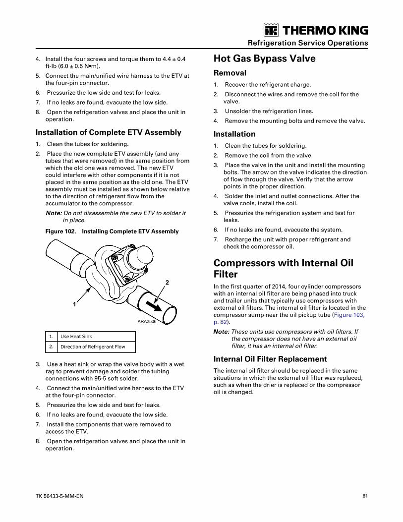
TK 56433-5-MM-EN 81
4. Install the four screws and torque them to 4.4 ± 0.4ft-lb (6.0 ± 0.5 N•m).
5. Connect the main/unified wire harness to the ETV atthe four-pin connector.
6. Pressurize the low side and test for leaks.
7. If no leaks are found, evacuate the low side.
8. Open the refrigeration valves and place the unit inoperation.
Installation of Complete ETV Assembly1. Clean the tubes for soldering.
2. Place the new complete ETV assembly (and anytubes that were removed) in the same position fromwhich the old one was removed. The new ETVcould interfere with other components if it is notplaced in the same position as the old one. The ETVassembly must be installed as shown below relativeto the direction of refrigerant flow from theaccumulator to the compressor.
NNoottee:: Do not disassemble the new ETV to solder itin place.
Figure 102. Installing Complete ETV Assembly
1. Use Heat Sink
2. Direction of Refrigerant Flow
3. Use a heat sink or wrap the valve body with a wetrag to prevent damage and solder the tubingconnections with 95-5 soft solder.
4. Connect the main/unified wire harness to the ETVat the four-pin connector.
5. Pressurize the low side and test for leaks.
6. If no leaks are found, evacuate the low side.
7. Install the components that were removed toaccess the ETV.
8. Open the refrigeration valves and place the unit inoperation.
Hot Gas Bypass ValveRemoval1. Recover the refrigerant charge.
2. Disconnect the wires and remove the coil for thevalve.
3. Unsolder the refrigeration lines.
4. Remove the mounting bolts and remove the valve.
Installation1. Clean the tubes for soldering.
2. Remove the coil from the valve.
3. Place the valve in the unit and install the mountingbolts. The arrow on the valve indicates the directionof flow through the valve. Verify that the arrowpoints in the proper direction.
4. Solder the inlet and outlet connections. After thevalve cools, install the coil.
5. Pressurize the refrigeration system and test forleaks.
6. If no leaks are found, evacuate the system.
7. Recharge the unit with proper refrigerant andcheck the compressor oil.
Compressors with Internal OilFilterIn the first quarter of 2014, four cylinder compressorswith an internal oil filter are being phased into truckand trailer units that typically use compressors withexternal oil filters. The internal oil filter is located in thecompressor sump near the oil pickup tube (Figure 103,p. 82).
NNoottee:: These units use compressors with oil filters. Ifthe compressor does not have an external oilfilter, it has an internal oil filter.
Internal Oil Filter ReplacementThe internal oil filter should be replaced in the samesituations in which the external oil filter was replaced,such as when the drier is replaced or the compressoroil is changed.
RReeffrriiggeerraattiioonn SSeerrvviiccee OOppeerraattiioonnss

82 TK 56433-5-MM-EN
Figure 103. Internal Oil Filter
1. Oil Discharge Tube 4. Pressure Relief Valve
2. O-Ring 5. Oil Pickup Tube
3. Internal Oil Filter 6. Stud On Oil Pickup Tube Bracket
1. Remove the compressor from the unit if needed toaccess the oil sump.
2. Remove the oil sump.
3. Remove the nut that fastens the internal oil filter tothe stud on the oil pickup tube bracket.
Figure 104. Remove Nut from Stud
1. Stud On Oil Pickup Tube Bracket
4. Remove the internal oil filter from the oil dischargetube.
Figure 105. Remove Internal Oil Filter from OilDischarge Tube
1. Internal Oil Filter
2. Oil Discharge Tube
5. Place the new internal oil filter on the oil dischargetube and the stud on the oil pickup tube bracket. Becareful to avoid damaging the O-ring in the oil filter.
6. Install and tighten the nut that fastens the internaloil filter to the stud on the oil pickup tube bracket.
7. Install the oil sump.
8. Install the compressor in the unit if it was removed.
Checking Compressor OilPressureThe oil pressure at the oil pressure access port varieswith the suction pressure in the compressor. Therefore,we need to calculate the “net oil pressure” todetermine the actual compressor oil pressure. The netoil pressure is the pressure at the oil pressure accessport minus the suction pressure below the throttlingvalve. Use the following procedure to check thecompressor oil pressure.
1. Attach a suitable oil pressure gauge to the oilpressure access port on the compressor oil filter, orto the oil pressure access port on the oil pumpcover.
2. Attach the low pressure gauge of a gauge manifoldto the fitting on the side of the throttling valve (orsuction valve adapter). This fitting allows you tomonitor the suction pressure in the compressorbelow the throttling valve.
3. Start the unit and note the pressure at the oilpressure access port and the suction pressurebelow the throttling valve.
4. Subtract the suction pressure below the throttlingvalve from the pressure at the oil pressure access
RReeffrriiggeerraattiioonn SSeerrvviiccee OOppeerraattiioonnss
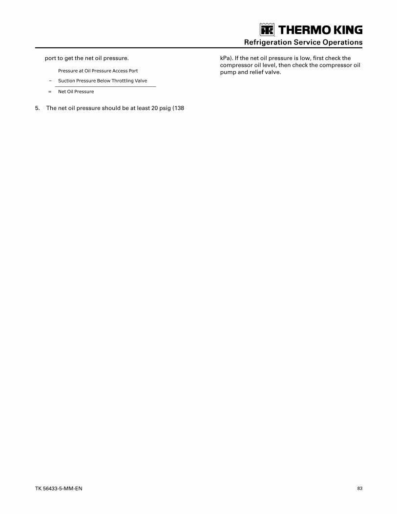
TK 56433-5-MM-EN 83
port to get the net oil pressure.
Pressure at Oil Pressure Access Port
– Suction Pressure Below Throttling Valve
= Net Oil Pressure
5. The net oil pressure should be at least 20 psig (138
kPa). If the net oil pressure is low, first check thecompressor oil level, then check the compressor oilpump and relief valve.
RReeffrriiggeerraattiioonn SSeerrvviiccee OOppeerraattiioonnss

84 TK 56433-5-MM-EN
Structural MaintenanceUnit and Engine Mounting BoltsCheck and tighten all unit and engine mounting boltsduring scheduled maintenance inspections.Torque theunit mounting bolts to 60 ft-lb (81 N•m). Torque theengine mounting bolts to 150 ft-lb (203 N•m).
Figure 106. Unit and Engine Mounting Bolts
1. Check Bolts for Tightness
Unit InspectionInspect the unit during pretrip inspection andscheduled maintenance inspections for loose or brokenwires or hardware, compressor oil leaks, or otherphysical damage which might affect unit performanceand require repair or replacement of parts.
Condenser, Evaporator, andRadiator CoilsClean the coils during scheduled maintenanceinspections. Remove any debris (e.g., leaves or plasticwrap) that reduces the air flow. Clean dirty coils withcompressed air or a pressure washer. Be careful not tobend the fins when cleaning a coil. If possible, blow theair or water through the coil in the direction oppositethe normal airflow. Repair bent fins and any othernoticeable damage.
Micro-Channel Coil CleaningRecommendations
Cleaning Intervals• The coils should be cleaned a Minimum of once a
year.
• It is recommended that any time the unit is in forservice or maintenance that the coils be inspectedand cleaned if needed.
• The coil should be cleaned if there are visibleaccumulations that obstruct the view of the fins ortubes of the coil.
• The coils should be cleaned if there is debrisimbedded in the tubes and fins.
The area and conditions in which the unit operates willdictate the cleaning intervals and method(s) needed.
Cleaning MethodsNNoottee:: Listed in order of recommended method.
• Take a cloth or towel and wipe the air side of thecoil going with the fins, across the tubes. See(Figure 108, p. 85) for results. The coil will clean in amanner similar to the way lint cleans from the linttrap of a household clothes dryer.
• Use a soft bristled brush (DO NOT USE AWIREBRUSH) and brush the coil going with the fins,across the tubes. The coil will clean in a mannersimilar to the way lint cleans from the lint trap of ahousehold clothes dryer.
• A vacuum with a soft attachment can be used tosuck the debris off the face as well as in the fins andtubes from the air side of the coil.
• Compressed air can be used and will work bestwhen blown thru the coil from the non-air sidewhen possible. Blowing thru from the airside mayimbed debris in the coil that was only on thesurface. It is recommended to start with one of thefirst three options before using compressed air ifthe non-air side is not accessible. The angle atwhich the air should be directed at the coil shouldnot be less than 75 degrees (Figure 109, p. 85).

TK 56433-5-MM-EN 85
• Power water sprayer may be used in pressuresunder 600 psi. Water will work best when blownthru the coil from the non-air side when possible.Spraying thru from the airside may imbed debris inthe coil that was only on the surface. It isrecommended to start with one of the first threeoptions before using water if the non-air side is notaccessible. The angle at which the water should bedirected at the coil should not be less than 75degrees (Figure 109, p. 85). The spray nozzle shouldbe kept between 1 inch and 3 inches (25 to 75millimetres) from the coil surface.
NNootteess::
1. Chemicals to aid in cleaning WILL VOIDWARRANTY and are NOT RECOMMENDED.
2. In some instances, it may take acombination of two methods to result in aclean coil. Such as, first wiping the coil toclean the surface and then using a vacuum,water or compressed air to clean down inthe fins. This will depend on the type ofdebris that needs to be cleaned from the coil.
3. Do not contact the coil with any hardvacuum nozzle, air nozzle, or any other tool.This will damage the tubes of the coil.
NNOOTTIICCEEEEqquuiippmmeenntt DDaammaaggee!!FFaaiilluurree ttoo ccoommppllyy wwiitthh aabboovvee mmeennttiioonneeddgguuiiddeelliinneess wwiillll lleeaadd ttoo aa sshhoorrtteenneedd lliiffee oofftthhee eeqquuiippmmeenntt ttoo aann iinnddeetteerrmmiinnaabbllee ddeeggrreeee..
Figure 107. Coil Before Cleaning
Figure 108. Coil after Wiping Right Hand Side withCloth
Figure 109. Source Angle for Cleaning with Air orWater
Defrost DrainsClean the defrost drains during scheduled maintenanceinspections to verify the lines remain open.
Unit InstallationAll nuts that hold the unit to the trailer are accessibleusing an impact wrench with a 10 inch (25 cm)extension, ball-type swivel, and a deep-well socket.
NNoottee:: The nuts for mounting the unit should be elasticstop nuts (Nylock type).
Defrost DamperThis unit uses a defrost damper that is actuated by adamper gear motor. The damper door is attacheddirectly to the damper gear motor shaft to simplify thelinkage.
SSttrruuccttuurraall MMaaiinntteennaannccee

86 TK 56433-5-MM-EN
Figure 110. Evaporator Blower Housing
1. Damper Stop 3. Damper Gear Motor
2. Damper Door (Open) 4. Scroll Panel
The unit is equipped with a base controller thatcontains a a damper gear motor drive to control thedamper gear motor. The base controller used in trailerunits without the damper gear motor will not work withthe damper gear motor. Make sure to order the correctbase controller if it is being replaced.
The defrost damper is open when the unit is in Cool orHeat, and closes when the unit is in Defrost. To close,the damper gear motor moves the damper door downuntil it contacts the top of the scroll panel. To open, thedamper gear motor moves the damper door up until itcontacts the damper stops.
Alarm Code 29 – Check Defrost Damper Circuit andAlarm Code 30 – Defrost Damper Stuck are associatedwith the defrost damper.
• Alarm Code 29 is set during the Pretrip Test if thecontroller senses a fault in the damper gear motoroperation.
• Alarm Code 30 is set any time the controller tries tomove the damper and the damper gear motordraws excessive current for a specified time.
In some conditions, such as when the unit is turned off,the damper is left in the last position to minimizeoperation and wear on the damper gear motor.
Testing Defrost DamperThe damper operation can be tested as part of thePretrip Test, or by using the Interface Board Test Mode.
PPrreettrriipp TTeesstt
• Closes then opens the damper
• Checks amp draw while damper moving
• Alarm Code 29 is recorded if the damper fails thetest.
IInntteerrffaaccee BBooaarrdd TTeesstt MMooddee
• This test is used to verify the damper will move.
• LED 31 Damper Door Open and LED 32 DamperDoor Close illuminate as required.
• The initial (breakaway) current draw occurs over avery short period of time and cannot be accuratelymeasured. Once the motor is running, the currentdraw should not exceed 0.8 amps.
• A technician must visually verify the damper willmove.
Troubleshooting Defrost DamperA problem with a damper will usually generate AlarmCode 29 or Alarm Code 30.
AAllaarrmm CCooddee 2299 –– CChheecckk DDeeffrroosstt DDaammppeerr CCiirrccuuiitt
Alarm Code 29 indicates that the amp draw on thedamper gear motor circuit was out of the expectedrange.
1. Visually check the damper door to see that is notdamaged and is attached to the damper gear motorshaft.
2. Use the Interface Board Mode to see if the dampermoves. Verify LED 31 Damper Door Open and LED32 Damper Door Close illuminate as required.
3. Check the continuity of the GMRED and GMBLKcircuits from the J15 connector on the basecontroller to damper gear motor.
4. Disconnect the damper gear motor harness fromthe main harness at the J16 connector near thedamper motor. Check the resistance of the dampergear motor between pins 1 and 2 in connector onthe damper gear motor harness. The resistanceshould be 4 to 5 ohms. If the resistance is out of thisrange, check the continuity of the wires from theconnector to the damper gear motor. If these wireshave good continuity, the damper gear motor isprobably defective.
AAllaarrmm CCooddee 3300 –– DDeeffrroosstt DDaammppeerr SSttuucckk
1. Visually check the damper door to see that is notdamaged, stuck, or frozen in place.
2. Use the Interface Board Mode to see if the dampermoves. Verify LED 31 Damper Door Open and LED32 Damper Door Close illuminate as required.
3. Check the continuity of the GMRED and GMBLKcircuits for a short to ground.
4. Disconnect the damper gear motor harness fromthe main harness at the J16 connector near thedamper motor. Check the resistance of the dampergear motor between pins 1 and 2 in connector onthe damper gear motor harness. The resistanceshould be 4 to 5 ohms. If the resistance is out of thisrange, check the continuity of the wires from the
SSttrruuccttuurraall MMaaiinntteennaannccee

TK 56433-5-MM-EN 87
connector to the damper gear motor. If these wireshave good continuity, the damper gear motor isprobably defective.
Replacing Damper Gear Motor1. Remove the evaporator access panels as necessary
to access the damper gear motor and damper door.
2. Remove the two bolts that attach the damper doorto the damper door shaft.
Figure 111. Removing Damper Door and GearMotor
1. Remove Bolts from Damper Door Shaft
2. Remove Bolts from Damper Gear Motor Shaft
3. Remove Screws from Damper Gear Motor (one notshown)
3. Remove the two bolts that attach the damper doorto the damper gear motor shaft and removedamper door.
4. Disconnect the damper gear motor harness fromthe main harness.
5. Remove the three screws that attach the dampergear motor to the evaporator blower housing andremove the damper gear motor. These screws arelocated on the inside of the evaporator blowerhousing.
6. Place the new damper gear motor in position andfasten it to the evaporator blower housing with thethree screws.
7. Reconnect the damper gear motor harness to themain harness.
8. Place the damper door in position and fasten it tothe damper gear motor shaft with the two bolts.
9. Fasten the damper door to the damper door shaftwith the two bolts.
10. Replace the evaporator access panels that wereremoved to access the damper gear motor anddamper door.
Condenser and Evaporator FanLocationWhen mounting the condenser or evaporator fan andhub assembly on the fanshaft, the blowers and inletorifices must be properly aligned for proper air flowand to prevent damage to the blower.
Condenser Inlet Orifice Alignment1. Loosen the condenser inlet orifice on the condenser
coil bulkhead.
2. Center the inlet orifice in the condenser blower andtighten the inlet orifice mounting hardware to holdthe inlet orifice in this position.
3. Check the radial clearance of the blower by passinga 0.09 in. (2.3 mm) gauge wire completely aroundthe circumference of the condenser orifice and thecondenser blower.
Figure 112. Condenser Inlet Orifice Alignment
1. Condenser Blower 4. Condenser CoilBulkhead
2. Check Clearance withWire
5. Radial Clearance
3. Inlet Orifice 6. Overlap 0.10-0.15 in.(2.5-3.8 mm)
Evaporator Fan Blower Alignment1. Loosen the inlet orifices on the sides of the blower
housing.
2. Center the blower wheel in the blower housing withequal overlap on both inlet orifices. The overlap oneach orifice should be approximately 0.15 in. (3.8mm).
3. Tighten the hub pinch bolts that hold the blower
SSttrruuccttuurraall MMaaiinntteennaannccee

88 TK 56433-5-MM-EN
wheel on the fan shaft to a torque of 13 ft-lb (18N•m).
4. Center the inlet orifices in the blower orifices.Tighten the inlet orifices securely.
5. Check the radial clearance by passing a 0.187 in.(4.75 mm) gauge wire completely around thecircumference of the inlet rings and the blowerwheel.
Figure 113. Evaporator Fan Location
1. Check Clearance withWire
4. Evaporator Blower
2. Blower Housing Sides 5. Radial Clearance
3. Inlet Orifices 6. Equalize Blower InletOverlap
Fan Shaft AssemblyThe unit is equipped with a fan shaft assembly thatcontains special sealed bearings. The bearings shouldbe checked when the belt is replaced. Spin the fan shaftwith the belt removed and listen. Unusually loudbearing noise indicates the fan shaft bearings shouldbe replaced.
Removal1. Remove the fan drive belt. See “Fan Drive Belt” in
the Engine Maintenance Chapter.
2. Remove the mounting hardware for the uppercondenser inlet orifice and remove it.
3. Loosen the hub pinch bolts on the upper condenserblower, slide the blower off the fan shaft andremove it. Make sure to remove and keep the key.
4. Loosen the hub pinch bolts on the evaporatorblower so it can slide on the fan shaft.
5. Remove the fan shaft mounting bolts.
6. Remove the fan shaft while sliding the evaporatorblower off the end of the fan shaft. Make sure toremove and keep the key.
NNoottee:: Make sure to avoid hitting the machinedsurface of the shaft against the structurebecause that could cause damage, making itdifficult to remove/install the bearings andcreate a starting point for further corrosion.
Disassembly1. Remove the snap ring from the condenser end.
2. Press the fan shaft out from condenser end to theevaporator end.
3. Remove the snap ring from the evaporator end.
4. Remove the bearings from the shaft by supportingthe bearing and tapping on the end of the shaft witha soft hammer. Make sure to avoid damaging theend of the shaft, which can make it difficult toremove/install the bearings.
5. Remove the bearing from the housing with ahammer and punch.
6. Clean and inspect the parts, but do not clean thebearings in solvent. Replace the parts that showsignificant wear or damage.
Figure 114. Fan Shaft Assembly
1. Snap Ring 6. Fan Shaft
2. Bearing (CondenserEnd)
7. Bearing (EvaporatorEnd)
3. Wave Washer 8. Wave Washer
4. Housing 9. Washer
5. Key
ReassemblyIImmppoorrttaanntt:: To prevent damage to the bearings, use
bearing drivers (or other suitable tools) onthe bearing races when installing thebearings.
1. Install one of the bearings on the evaporator end ofthe fan shaft.
SSttrruuccttuurraall MMaaiinntteennaannccee

TK 56433-5-MM-EN 89
2. Install the two washers on the evaporator end of thefan shaft.
3. Install the wave washer on the evaporator end ofthe fan shaft.
4. Install the other bearing on the evaporator end ofthe fan shaft (with the washers between the twobearings).
5. Install the snap ring on the evaporator end of thefan shaft.
6. Use a wire brush in the machined bore in theevaporator end of the housing to remove oxide andother contaminants.
Figure 115. Fan Shaft Housing
1. Use Wire Brush to Clean Bore
7. Clean the machined bore in the evaporator end ofthe housing and the outer races of the bearings onthe evaporator end of the fan shaft with Loctite 7063cleaner. The cleaner needs to be sprayed on, wipeddown and then allowed to evaporate dry.
IImmppoorrttaanntt:: The cleaner must be allowed toevaporate before the next step.
Figure 116. Fan Shaft and Housing
1. Clean Bore with Loctite 7063 Cleaner
2. Clean Outer Races with Loctite 7063 Cleaner
8. Apply Loctite 7240 (activator) to the machined bore(inner surface) in the evaporator end of the housingand allow it to dry by evaporation.
Figure 117. Fan Shaft Housing
1. Apply Loctite 7240 (Activator) to Machined Bore (InnerSurface)
9. Apply a bead of Loctite 603 to the leading edge ofthe machined bore in the evaporator end of thehousing and to the outer races of the bearings onthe evaporator end of the fan shaft.
Figure 118. Fan Shaft Housing
1. Apply Bead of Loctite 603 to Leading Edge of MachinedBore
SSttrruuccttuurraall MMaaiinntteennaannccee

90 TK 56433-5-MM-EN
Figure 119. Fan Shaft and Housing
1. Apply Bead of Loctite 603 to Leading Edge
2. Apply Bead of Loctite 603 to Outer Races
10. Insert the fan shaft and bearings into the evaporatorend of the housing. Make sure the bonding surfacesof the housing and bearings are well covered withLoctite 603.
NNoottee:: Loctite 603 and Loctite 7240 (activator) willbegin to bond within seconds upon contact.
NNoottee:: Curing time for Loctite 603 is 6 hours whenLoctite 7240 (activator) has been used. Do notinstall the fan shaft in the unit until the Loctitehas cured.
11. Install the wave washer on the condenser end of thefan shaft.
12. Install the bearing on the condenser end of the fanshaft.
13. Install the snap ring on the condenser end of the fanshaft.
Installation1. Make sure the key is in place in the evaporator end
of the fan shaft.
2. Install the fan shaft while sliding the evaporatorblower onto the end of the fan shaft.
3. Install and tighten the fan shaft mounting bolts.
4. Center the evaporator blower in the blower housingwith equal overlap on both inlet orifices and tightenthe hub pinch bolts (see “Evaporator Fan BlowerAlignment” above).
5. Make sure the key is in place in the condenser endof the fan shaft.
6. Place the upper condenser blower on the fan shaftand slide it into position to where its pulley isaligned correctly with the other pulleys and tightenthe hub pinch bolts.
7. Install the upper condenser inlet orifice. Center it inthe upper condenser blower and tighten the
mounting hardware (see “Condenser Inlet OrificeAlignment” above).
8. Install the fan drive belt. See “Fan Drive Belt” in theEngine Maintenance Chapter.
Lower Condenser BlowerAssemblyThe lower condenser blower assembly contains specialsealed bearings. The bearings should be checked whenthe belt is replaced. Spin the lower condenser blowerwith the belt removed and listen. Unusually loudbearing noise indicates the lower condenser blowerbearings should be replaced.
Removal1. Remove the fan drive belt. See “Fan Drive Belt” in
the Engine Maintenance Chapter.
2. Remove the mounting hardware for the lowercondenser inlet orifice and remove it.
3. Remove the hardware that fastens the blowerspindle to the spindle mounting bracket andremove the lower condenser blower assembly.
Disassembly1. Remove the snap ring.
2. Remove the spindle and wave washers from theblower hub.
3. Remove the bearings from the blower hub with ahammer and punch.
4. Clean and inspect the parts, but do not clean thebearings in solvent. Replace the parts that showsignificant wear or damage.
SSttrruuccttuurraall MMaaiinntteennaannccee

TK 56433-5-MM-EN 91
Figure 120. Lower Condenser Blower Assembly
1. Spindle MountingBracket
5. Bearing
2. Blower Spindle 6. Blower Hub
3. Wave Washer 7. Snap Ring
4. Blower Pulley 8. Blower
ReassemblyIImmppoorrttaanntt:: To prevent damage to the bearings, use
bearing drivers (or other suitable tools) onthe bearing races when installing thebearings.
1. Install the bearings in the hub.
2. Place the wave washers on the spindle.
3. Insert the spindle and wave washers into theblower hub.
4. Install the snap ring.
Installation1. Place the lower condenser blower assembly in
position and install the hardware that fastens theblower spindle to the spindle mounting bracket.
2. Install the lower condenser inlet orifice. Center it inthe lower condenser blower and tighten themounting hardware (see “Condenser Inlet OrificeAlignment” above).
3. Install the fan drive belt. See “Fan Drive Belt” in theEngine Maintenance Chapter.
Cross Shaft AssemblyThe unit is equipped with a cross shaft assembly thatcontains special sealed bearings. The bearings shouldbe checked when the belt is replaced. Spin the crossshaft with the belt removed and listen. Unusually loudbearing noise indicates the cross shaft bearings shouldbe replaced.
Removal1. Remove the fan drive belt. See “Fan Drive Belt” in
the Engine Maintenance Chapter.
2. Remove the engine/cross shaft belt. See “Engine/Cross Shaft Belt” in the Engine MaintenanceChapter.
3. Loosen the pinch bolts on the cross shaft/fan pulleyand remove it from the cross shaft.
4. Loosen the pinch bolts on the cross shaft/enginepulley and remove it from the cross shaft.
5. Mark one or both ends of the cross shaft housing toidentify which is the engine pulley end and which isthe fan pulley end.
6. Remove the cross shaft mounting bolts and removethe cross shaft.
Disassembly1. Remove the snap rings.
2. Remove the cross shaft from the housing bytapping on either end of the cross shaft with a softhammer. Make sure to avoid damaging the end ofthe shaft, which can make it difficult to remove/install the bearings.
NNoottee:: The engine pulley end of the cross shaft has athreaded hole in it, and the fan pulley enddoes not.
3. Remove the bearing from the shaft by supportingthe bearing and tapping on the end of the shaft witha soft hammer.
4. Remove the bearing from the housing with ahammer and punch.
5. Clean and inspect the parts, but do not clean thebearings in solvent. Replace the parts that showsignificant wear or damage.
SSttrruuccttuurraall MMaaiinntteennaannccee

92 TK 56433-5-MM-EN
Figure 121. Cross Shaft Assembly
1. Snap Ring 5. Cross Shaft
2. Bearing 6. Key
3. Wave Washer 7. Engine Pulley End
4. Housing 8. Fan Pulley End
ReassemblyIImmppoorrttaanntt:: To prevent damage to the bearings, use
bearing drivers (or other suitable tools) onthe bearing races when installing thebearings.
NNoottee:: Place a thin layer of grease (Mobil 28 or itsequivalent) on the inner and outer bearing racesbefore assembly.
1. Install a bearing on the fan pulley end of the crossshaft. The fan pulley end does not have a threadedhole.
2. Install the snap ring on the fan pulley end of thecross shaft.
3. Insert the cross shaft and bearing into the fan pulleyend of the housing.
4. Install the wave washer on the engine pulley end ofthe cross shaft.
5. Install the other bearing on the engine pulley end ofthe cross shaft.
6. Install the snap ring on the engine pulley end of thecross shaft.
Installation1. Place the cross shaft in position. Make sure with the
engine pulley end is located on the engine/crossshaft belt side.
2. Install and tighten the cross shaft mounting bolts.
3. Make sure the key is in place in the engine pulleyend of the cross shaft.
4. Place the cross shaft/engine pulley on the crossshaft. Position it axially using block P/N 2042435between the pulley and the cross shaft mountingbracket and tighten the pinch bolts.
5. Make sure the key is in place in the fan pulley end ofthe cross shaft.
6. Place the cross shaft/fan pulley on the cross shaft,slide it into position to where it is aligned correctlywith the other pulleys and tighten the pinch bolts.
7. Install the engine/cross shaft belt. See “Engine/Cross Shaft Belt” in the Engine MaintenanceChapter.
8. Install the fan drive belt. See “Fan Drive Belt” in theEngine Maintenance Chapter.
Idler AssembliesThe idler assemblies contains special sealed bearings.The bearings should be checked when the belt isreplaced. Spin the idler pulley with the belt removedand listen. Unusually loud bearing noise indicates theidler bearings should be replaced. The idler assemblyfor the idler pulley in the engine/cross shaft belt isshown below. The other idler assemblies are similar.See the appropriate Parts Manual.
Figure 122. Typical Idler Assembly
1. Spindle 4. Idler Pulley
2. Washer 5. Snap Ring
3. Bearing
Disassembly1. Remove the appropriate belt. See “Engine/Cross
Shaft Belt” or “Fan Drive Belt” in the EngineMaintenance Chapter.
2. Remove the snap ring and discard it.
3. Remove the idler pulley and bearings from thespindle.
4. Remove the washers from the spindle and discardthem.
SSttrruuccttuurraall MMaaiinntteennaannccee
TK 56433-5-MM-EN 93
5. Remove the bearings from the idler pulley with ahammer and punch.
6. Clean and inspect the parts, but do not clean thebearings in solvent. Replace the parts that showsignificant wear or damage.
ReassemblyIImmppoorrttaanntt:: To prevent damage to the bearings, use
bearing drivers (or other suitable tools) onthe bearing races when installing thebearings.
1. Install the bearings in the idler pulley.
2. Place new washers on the spindle.
3. Place the idler pulley and bearings on the spindle.
4. Install a new snap ring.
5. Install the belt. See “Engine/Cross Shaft Belt” or“Fan Drive Belt” in the Engine MaintenanceChapter.
SSttrruuccttuurraall MMaaiinntteennaannccee

94 TK 56433-5-MM-EN
Mechanical Diagnosis
CONDITION POSSIBLE CAUSE REMEDY
Engine will not crank Electrical problem Check and repair electrical system
Defective starter solenoid Replace solenoid
Defective starter Repair starter
Water in cylinders Check for hydrostatic lock. Remove injectors and turnengine slowly
Starter motor turns but engine doesnot crank
Starter clutch defective Replace
Engine cranks but fails to start Fuel solenoid not energized Check 8D and 8DP and CHF circuits and fuel solenoidpull-in relay. Check that controller is configured forthe correct engine. Refer to appropriateMicroprocessor Diagnostic Manual.
Fuel solenoid defective or stuck Replace
Fuel injection pump defective Replace pump
Air heater defective Replace
No fuel or wrong fuel Fill with proper fuel
Fuel transfer pump defective Replace transfer pump
Air in fuel system Bleed air
Compression low Overhaul engine
Injection nozzles defective Replace nozzles
Incorrect timing Adjust timing
Air cleaner clogged Replace air filter
Exhaust plugged Clean exhaust
Engine stops after starting Air in injection pump Bleed fuel system
Fuel filter obstructed Replace filter element
Vent of fuel tank obstructed Unclog vent
Clogged fuel tank or fuel lines Clean fuel tank and fuel lines
High head pressure Eliminate cause of high head pressure

TK 56433-5-MM-EN 95
CONDITION POSSIBLE CAUSE REMEDY
Engine does not develop full power Air intake system clogged Clean air intake system
Fuel tank vent clogged Unclog vent
Clogged fuel tank or fuel lines Clean fuel tank and fuel lines
Speed adjustment wrong Adjust speed
Insufficient fuel volume leaving filter Check for dirty filter or air in system
Air cleaner clogged Replace air filter
Delivery of fuel pump insufficient Repair pump
Injection pump timing off Adjusting timing
Injection nozzles defective Repair or replace nozzles
Worn injection pump plungers, deliveryvalve defective, injection rate too low,gum formations
Repair or replace pump
Compression low or unbalanced Overhaul engine
Engine speed too high Misadjusted high speed solenoid Adjust high speed solenoid
Defective injection pump Repair injection pump
Engine fails to stop when unit is OFF Fuel solenoid defective Replace
Injection pump defective Replace pump
Engine knocks heavily Air in system Bleed fuel system
Wrong fuel Change fuel
Injection pump not timed Retime injection pump
Injection nozzles fouled or openingpressure too low
Clean, repair or replace injection nozzles
Delivery valve spring broken Replace spring or repair injection pump
Compression too low Overhaul engine
Valve out of adjustment Adjust valves
Fuel return line plugged Remove return line restriction
Rod or main bearing worn Replace rod or main bearings
Engine runs hot Dirty radiator Wash radiator
Coolant level is low Add coolant
Cooling system heavily scaled Clean cooling system
Cylinder head gasket leaks Replace cylinder head gasket. Use correct gasket
Faulty thermostat Check or replace thermostat
Loose or worn water pump belt Replace belt
Oil pressure low Insufficient oil in pan Add oil
Faulty oil pressure switch Check oil pressure switch. Replace if necessary
Oil control valve defective Check oil pressure control valve
Worn oil pump, camshaft, main orconnecting rod bearings, loose oil galleryplug
Repair engine
MMeecchhaanniiccaall DDiiaaggnnoossiiss

96 TK 56433-5-MM-EN
CONDITION POSSIBLE CAUSE REMEDY
High oil consumption 10 hour engine break in running was notsuccessfully completed
Run unit for 10 hours on high speed continuous runwith trailer doors open as described in the “Unit CheckList” section at the end of the appropriate InstallationManual
Oil leakage Check and eliminate possible causes at rocker armcover, oil lines, oil filter, front timing cover, orcrankshaft seals
Damaged valve seals Replace seals on valve stem
Worn valve stem Replace valves
Broken piston rings or cylinder bore wornor scored
Have engine repaired and rebored. Replace brokenpiston rings
Clogged air cleaner system Unclog air cleaner
Engine Emits Excessive Smoke
White Smoke Black Smoke Blue Smoke
Fuel is not burning Excessive Fuel to Air Ratio Oil Consumption
• Air or water in fuel
• Incorrect timing
• Poor compression
• Faulty injectors
• Type of fuel used
• Cold engine
• Excessive load
• Clogged air intake system
• Faulty nozzles
• Poor compression
• Restricted exhaust
• Faulty injection pump
• Poor compression
• Defective valve seals
MMeecchhaanniiccaall DDiiaaggnnoossiiss

TK 56433-5-MM-EN 97
Refrigeration Diagnosis
Rapidcyclingbetweencoolandheat
Unitcoolsinheatanddefrostcycle
Unitheatsinrefrigerationcycle
Highheadpressure
Lowheadpressure
Highsuctionpressure
Lowsuctionpressure
Nosuctionpressure
Unitoperatinginavacuum
Receiversightglassempty
Suctionlinefrostingback
Unabletopumpdownsystem
Unabletopullvacuuminlowside
Unabletoholdvacuuminlowside
Noisycompressor
Unitnotrefrigerating
Unitnotheatingordefrosting
SYMPTOM
POSSIBLE CAUSES
• • • • Overcharge of refrigerant
• • • • • • Shortage of refrigerant
• • • • • No refrigerant
• Air through condenser too hot (ambient)
• Air flow through condenser restricted
• • • Air through condenser too cold (ambient)
• • • Air in refrigerant system
• Condenser fan blades bent or broken
• Air short cycling around evaporator coil
• Air through evaporator restricted
• • • • Evaporator needs defrosting
• • Compressor discharge valves leaking
• • Compressor suction valves leaking
• Too much compressor oil in system
• Faulty oil pump in compressor
• Faulty compressor drive coupling
• Compressor bearing loose or burned out
• • • • • Broken valve plate in compressor
• • Expansion valve power element lost its charge
• • Expansion valve feeler bulb improperly mounted
• • • Expansion valve feeler bulb making poor contact
• • Expansion valve open too much
• • Expansion valve closed too much
• • Expansion valve needle eroded or leaking
• • • Expansion valve partially closed by ice, dirt or wax
• • • Liquid refrigerant entering compressor
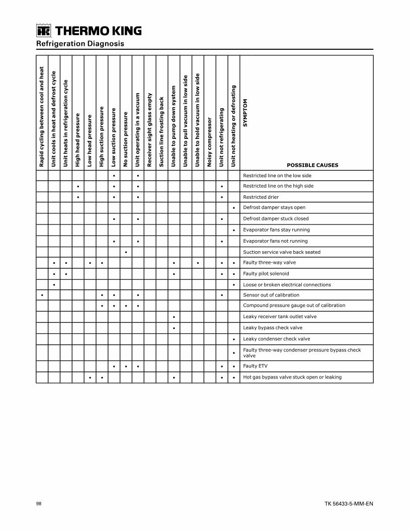
98 TK 56433-5-MM-EN
Rapidcyclingbetweencoolandheat
Unitcoolsinheatanddefrostcycle
Unitheatsinrefrigerationcycle
Highheadpressure
Lowheadpressure
Highsuctionpressure
Lowsuctionpressure
Nosuctionpressure
Unitoperatinginavacuum
Receiversightglassempty
Suctionlinefrostingback
Unabletopumpdownsystem
Unabletopullvacuuminlowside
Unabletoholdvacuuminlowside
Noisycompressor
Unitnotrefrigerating
Unitnotheatingordefrosting
SYMPTOM
POSSIBLE CAUSES
• • Restricted line on the low side
• • • • Restricted line on the high side
• • • • Restricted drier
• Defrost damper stays open
• • • Defrost damper stuck closed
• Evaporator fans stay running
• • • Evaporator fans not running
• Suction service valve back seated
• • • • • • • • Faulty three-way valve
• • • • • Faulty pilot solenoid
• • Loose or broken electrical connections
• • • • • Sensor out of calibration
• • • • Compound pressure gauge out of calibration
• Leaky receiver tank outlet valve
• Leaky bypass check valve
• Leaky condenser check valve
• Faulty three-way condenser pressure bypass checkvalve
• • • • • Faulty ETV
• • • • • Hot gas bypass valve stuck open or leaking
RReeffrriiggeerraattiioonn DDiiaaggnnoossiiss

TK 56433-5-MM-EN 99
Refrigeration DiagramsCool Cycle

100 TK 56433-5-MM-EN
1. Compressor 18. Equalizer Line
2. Discharge Service Valve 19. Distributor
3. Discharge Vibrasorber 20. Evaporator Coil
4. Discharge Line 21. Suction Line
5. Three-Way Valve 22. Accumulator
6. Three-Way By-pass Check Valve 23. Suction Vibrasorber
7. Condenser Coil 24. Suction Service Valve
8. Condenser check valve 25. Hot Gas Bypass Solenoid
9. High Pressure Relief Valve 26. Pilot Solenoid
10. Receiver Tank 27. Hot Gas Line
11. Sight Glass 28. Defrost Pan Heater
12. Receiver outlet valve 29. Bypass Check Valve
13. Liquid Line 30. Bypass Service Valve
14. Drier 31. Electronic Throttling Valve
15. Heat Exchanger 32. Suction Solenoid
16. Expansion Valve 33. Discharge Transducer
17. Feeler Bulb
RReeffrriiggeerraattiioonn DDiiaaggrraammss

TK 56433-5-MM-EN 101
Heat/Defrost Cycle
RReeffrriiggeerraattiioonn DDiiaaggrraammss

102 TK 56433-5-MM-EN
1. Compressor 18. Equalizer Line
2. Discharge Service Valve 19. Distributor
3. Discharge Vibrasorber 20. Evaporator Coil
4. Discharge Line 21. Suction Line
5. Three-Way Valve 22. Accumulator
6. Three-Way By-pass Check Valve 23. Suction Vibrasorber
7. Condenser Coil 24. Suction Service Valve
8. Condenser check valve 25. Hot Gas Bypass Solenoid
9. High Pressure Relief Valve 26. Pilot Solenoid
10. Receiver Tank 27. Hot Gas Line
11. Sight Glass 28. Defrost Pan Heater
12. Receiver outlet valve 29. Bypass Check Valve
13. Liquid Line 30. Bypass Service Valve
14. Drier 31. Electronic Throttling Valve
15. Heat Exchanger 32. Suction Solenoid
16. Expansion Valve 33. Discharge Transducer
17. Feeler Bulb
RReeffrriiggeerraattiioonn DDiiaaggrraammss

TK 56433-5-MM-EN 103
Diagram Index
The following table lists the diagrams that are relevantto this unit.
The diagrams are available on TSA Info Central and inthe SLXi-DRC Diagrams Manual TK 56504.
Drawing No. Drawing Title
3E31534 Schematic Diagram
2E98198 Wiring Diagram

Thermo King – by Trane Technologies (NYSE: TT), a global climate innovator – is a worldwide leader in sustainabletransport temperature control solutions. Thermo King has been providing transport temperature control solutionsfor a variety of applications, including trailers, truck bodies, buses, air, shipboard containers and railway cars since1938. For more information, visit www.thermoking.com or www.tranetechnologies.com.
Thermo King has a policy of continuous product and product data improvements and reserves the right to change design and specificationswithout notice. We are committed to using environmentally conscious print practices.
TK 56433-5-MM-EN 01 Aug 2018
Supersedes TK 56433-5-MM-EN (August 2017) ©2020 Trane Technologies