Embed Size (px)
Citation preview

Report 03/2015April 2015
Rail Accident Report
Derailment of an empty passenger train at Paddington station25 May 2014

This investigation was carried out in accordance with:
l the Railway Safety Directive 2004/49/EC;l the Railways and Transport Safety Act 2003; and l the Railways (Accident Investigation and Reporting) Regulations 2005.
© Crown copyright 2015 You may re-use this document/publication (not including departmental or agency logos) free of charge in any format or medium. You must re-use it accurately and not in a misleading context. The material must be acknowledged as Crown copyright and you must give the title of the source publication. Where we have identified any third party copyright material you will need to obtain permission from the copyright holders concerned. This document/publication is also available at www.raib.gov.uk.
Any enquiries about this publication should be sent to:
RAIB Email: [email protected] Wharf Telephone: 01332 253300Stores Road Fax: 01332 253301 Derby UK Website: www.gov.uk/raibDE21 4BA
This report is published by the Rail Accident Investigation Branch, Department for Transport.

Report 03/2015Paddington
3 April 2015
Derailment of an empty passenger train at Paddington station, 25 May 2014
Contents
Summary 5Introduction 6
Preface 6Key definitions 6
The accident 7Summary of the accident 7Context 9Events preceding the accident 15Events during the accident 15Events following the accident 16
The investigation 17Sources of evidence 17
Key facts and analysis 18Post-tyre turning procedure 18Identification of the immediate cause 19Identification of causal and underlying factors 20Observations 36
Summary of conclusions 37Immediate cause 37Causal factors 37Underlying factors 38Additional observations 38
Previous RAIB recommendations relevant to this investigation 39Actions reported as already taken or in progress relevant to this report 40
Actions reported that address factors which otherwise would have resulted in a RAIB recommendation 40Other reported actions 40
Recommendations 42

Report 03/2015Paddington
4 April 2015
Appendices 44Appendix A - Glossary of abbreviations and acronyms 44Appendix B - Glossary of terms 45Appendix C - Urgent Safety Advice 48

Report 03/2015Paddington
5 April 2015
Summary
At around 05:20 hrs on Sunday 25 May 2014, the third vehicle of an empty five car class 360/2 passenger train manufactured by Siemens and operated by Heathrow Express derailed while it was running along platform 3 at London Paddington station. All four wheels on the leading bogie of the third vehicle became derailed on a track defect which, according to Network Rail’s standards, required a repair within 36 hours. No one was injured as a result of the derailment.The derailment occurred because the bogies of the third vehicle were incorrectly set up, which resulted in the left-hand wheels of the leading bogie being partially unloaded even when stationary. The track defect along platform 3 exacerbated this unloading and contributed to the derailment.The investigation has found that the incorrect setup was the result of the repeated implementation by Siemens technicians of a procedure aimed at setting the vehicle ride heights following tyre turning or bogie replacement. This procedure did not clearly instruct the technicians on how to adjust one of the bogie components (the anti-roll bar) which resulted in the technicians setting it in such a way as to create the wheel load imbalance. None of the checks in the procedure identified the incorrect setup because these checks were not monitoring parameters likely to provide a clear indication of a wheel load imbalance. An underlying factor was the lack of effective transfer of design information about the role and importance of the anti-roll bars between the vehicle designers (Siemens Germany) and the vehicle maintainers (Siemens UK).The track defect had been repeatedly identified by Network Rail’s measurements of track geometry for at least three years. However the required processes to remedy the defect were not followed and this was not picked up by Network Rail’s assurance process. As a result of this investigation, the RAIB has made four recommendations to Siemens and one to Network Rail. The recommendations to Siemens relate to the revision of the procedure used to set the vehicle ride heights, training materials and competence assessments to capture the function of anti-roll bars, their method of adjustment and the risks associated with incorrect setup. The recommendations also cover a review of other maintenance procedures and a review of the effectiveness of Siemens’ recently developed processes for transfer of design information into maintenance procedures.The recommendation on Network Rail is to review its supervision and self-assurance arrangements to identify shortcomings which led to the non-compliances with a mandated standard going unnoticed.
Sum
mar
y

Report 03/2015Paddington
6 April 2015
Introduction
Preface1 The purpose of a Rail Accident Investigation Branch (RAIB) investigation is to
improve railway safety by preventing future railway accidents or by mitigating their consequences. It is not the purpose of such an investigation to establish blame or liability.
2 Accordingly, it is inappropriate that RAIB reports should be used to assign fault or blame, or determine liability, since neither the investigation nor the reporting process has been undertaken for that purpose.
3 The RAIB’s investigation (including its scope, methods, conclusions and recommendations) is independent of all other investigations, including those carried out by the safety authority or railway industry.
Key definitions4 The report contains abbreviations and technical terms (shown in italics the first
time they appear in the report). These are explained in appendices A and B.5 All dimensions in this report are given in metric units, except speeds and locations
which are given in imperial units, in accordance with normal railway practice. Where appropriate the equivalent metric value is also given. All locations in this report are relative to a zero reference point located within London Paddington station. The buffer stops at Paddington station are reported as being located 5 chains from this reference point. The directions left and right in this report are relative to the direction of travel of the train.
Introduction

Report 03/2015Paddington
7 April 2015
The
acci
dentThe accident
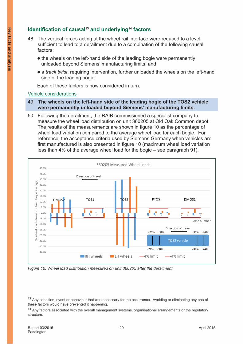
Summary of the accident 6 On Sunday 25 May 2014 train reporting number 5T081, the 05:04 hrs Heathrow
Express empty stock movement from Old Oak Common to Paddington, derailed in platform 3 at Paddington station. As this was the first move of the day in preparation for the train entering passenger service, the only person on board was the driver. He was not hurt during the derailment. The RAIB has investigated this accident as it had the potential, under slightly different circumstances, for more serious consequences.
Figure 1: Location of the derailment
7 Train 5T08 was a five-car electric multiple unit. Both wheelsets on the leading bogie of the third vehicle derailed to the left, in the six-foot, on a right-hand curve (figure 2). The vehicle ran derailed for approximately 100 metres and damaged some track components in the process. There was only minimal damage to the vehicle itself.
1 An alphanumeric code, known as the train reporting number, is allocated to every train operating on Network Rail’s infrastructure for the purpose of tracking train movement on the network.
Location of accident
© Crown Copyright. All rights reserved. Department for Transport 100039241. RAIB 2015

Report 03/2015Paddington
8 April 2015
Figure 2: Final resting position of derailed vehicle at Paddington station platform 3
The accident

Report 03/2015Paddington
9 April 2015
Point of derailment
Platform 3
Direction of travel
ContextLocation8 Paddington station has 14 mainline platforms. It is the London terminus for First
Great Western services to and from the west of England and South Wales. It is also the terminus for local services including Heathrow Express services to and from London Heathrow airport.
9 The derailment of the third vehicle of train 5T08 took place adjacent to platform 3, approximately 153 metres from the buffer stops (figure 3). The track at this location and in the direction of travel is on a transition from a 300 metre radius right-hand curve to straight track. The curve radius at the point of derailment is approximately 500 metres and according to Network Rail’s Sectional Appendix, the maximum linespeed at this location is 40 mph (64 km/h). Trains in and out of Paddington station travel slower than this as they are either slowing down to stop or accelerating from rest.
Figure 3: Overview of the derailment location
Organisations involved10 The train was owned and operated by Heathrow Express, who also employed the
driver. Its unit number is 360205 and it is one of five class 360/2 trains maintained at Old Oak Common depot by Siemens, who also employed the technicians and supervisors in charge of maintenance. Heathrow Express’ class 332 fleet is also maintained at Old Oak Common depot by the same technicians and supervisors.
11 Network Rail owns, operates and maintains the infrastructure where the derailment took place. Paddington station, part of Network Rail’s western route, is maintained by the Reading maintenance delivery unit.
The
acci
dent

Report 03/2015Paddington
10 April 2015
Primary suspension
Secondary suspension
(hidden)
DMOS1 - 78435 PTOS - 63425 TOS2 - 72435 TOS1 - 72425 DMOS2 - 78445
Direction of travel
Driving motor open standard
Driving motor open standard
Trailer open standard
Trailer open standard
Pantograph trailer open standard
12 All parties freely co-operated with the investigation and provided assistance during the course of the investigation.
Train involved13 The class 360/2 fleet was designed and manufactured by Siemens in Germany
based on the Desiro UK family of multiple unit vehicles. These vehicles are fitted with bogies of the SF5000 type, which was designed and manufactured by Siemens in Austria.
14 The formation of unit 360205 is shown in figure 4. The derailed vehicle was the TOS2 vehicle, number 72435.
Figure 4: unit 360205 formation
Rail equipment/systems involved15 Railway passenger vehicles, including the class 360/2 vehicles, are designed with
two stages of suspension to maximise the comfort of the passengers. These are known as the primary and secondary suspensions (figures 5, 6 and 7).
Figure 5: SF5000 bogie
The accident

Report 03/2015Paddington
11 April 2015
Primary Spring
Bush
Axlebox
Primary Damper
Z1 dimension
Bogie frame
16 The primary suspension is normally formed by a set of springs and dampers located between the axleboxes and bogie frame. The primary suspension reduces the accelerations transferred to the bogie frame. Figure 6 shows the primary suspension using a radial arm axlebox as fitted to the SF5000 bogie. Figure 6 also illustrates the dimension known on the SF5000 bogie design as the Z1 dimension: this is the distance between the top of the axlebox and the underside of the bogie frame.
Figure 6: Primary suspension (SF5000 bogie)
17 The secondary suspension is an air suspension system with two large airbags fitted between each bogie frame and the carbody. The airbags are moderately soft springs which further reduce the accelerations transferred to the carbody and hence to the passengers. The airbags are fed from one, or two, auxiliary reservoirs. The pressure inside the airbags is automatically adjusted depending on the passenger loading condition to maintain the ride height of the carbody (paragraph 20). The airbags sit on auxiliary springs (made out of rubber on the class 360/2) which ensure a minimum comfort and safety level if the airbags should unexpectedly deflate or the air supply is lost. As the wheel diameter reduces through tyre turning following wear, the height of the carbody can be maintained by packing under the auxiliary spring using shims. At Siemens, this operation is called the post tyre turning (PTT) intervention. Figure 7 shows the secondary suspension on the SF5000 bogie.
18 With this secondary suspension arrangement, the carbody will tend to roll even under moderate lateral accelerations (eg going round a gentle curve). In order to control the amount of roll experienced by the carbody (and its passengers), the class 360/2 vehicles, like most other railway passenger vehicles, are fitted with a mechanical restraint between the carbody and each bogie known as an anti-roll bar.
The
acci
dent

Report 03/2015Paddington
12 April 2015
Bogie frame
Airbag
Secondary packing (shims)
Auxiliary spring
Bolster
Bearings (hidden)
Offset connection
Anti-roll bar links
(adjustable)
Anti-roll bar
Figure 7: Secondary suspension (SF5000 bogie)
Figure 8: Anti-roll bar on SF5000 bogie (bolster mounted)
The accident

Report 03/2015Paddington
13 April 2015
Levelling valve
Operating lever
Operating lever
Levelling valve
19 The anti-roll bar is a round bar (51 mm diameter solid steel bar on class 360/2) which runs transversely beneath the carbody (figure 8). The bar is supported by bearings connecting it to the carbody at either end which means that it can freely rotate along its axis. There is normally one anti-roll bar per bogie (two per vehicle). The ends of the bar are formed to create an off-centre connection to the bogie frame via the anti-roll bar links. It is this offset connection which defines the behaviour of the anti-roll bar. As the carbody bounces up and down, both ends of the bar are pushed up or pulled down by the links and the bar rotates in its bearings without adding any resistance to the vertical movement. As the body rolls, one end of the bar is pushed up by the link and the other side is pulled down by the other link. This has the effect of loading the bar in torsion. As the bar is torsionally stiff, it limits the differential movement that can be experienced at the ends and hence it controls the amount of roll seen by the carbody. This is a fairly typical arrangement on a modern passenger vehicle2.
20 Another important connection between the carbody and the bogie frame is the levelling valve. For gauge clearance purposes and to maintain the ride quality, it is necessary to keep the carbody at a consistent height for all loading conditions (ie from an empty vehicle to a vehicle full of passengers). This is achieved by the levelling valve and its operating lever. The operating lever actuates the levelling valve in response to changes in the vertical distance between the underside of the carbody and the bogie. If the distance decreases because of an increase in passenger load, the lever activates the valve to increase the pressure in the airbags which raises the carbody. If the distance increases because of a decrease in passenger load, the lever activates the valve to reduce the pressure in the airbags which lowers the carbody. In normal running, the levelling valve is designed to ignore small vertical movements and responds only to large deflections. On the SF5000 bogie, in common with many other Siemens’ designs, both airbags are interconnected through the bolster on each bogie and the air pressure controlled by a single levelling valve, as shown on figure 9. Other designs may have separate levelling valves independently controlling the pressure to each airbag.
Figure 9: Single levelling valve system (SF5000 bogie)
2 On class 360/2, the anti-roll bar is built into the bolster and hence becomes an integral part of the carbody once fully assembled. On many other vehicles, the anti-roll bar is held within the bogie frame and connected to the underside of the carbody but the principle remains the same.
The
acci
dent

Report 03/2015Paddington
14 April 2015
21 Railway vehicles are also designed so that the weight on the bogies from the carbody and all its equipment is evenly distributed. This is to ensure that all wheels carry an even amount of load to the track, hence minimising track damage while controlling the risk of derailment due to wheel unloading.
22 Train manufacturers design vehicles to ensure that the centre of gravity is as close as possible to the geometrical centre of the vehicle but practical limitations due to the size and mass of the equipment fitted on the carbody means that it can sometimes be difficult to achieve a perfect outcome. Therefore the centre of gravity of the carbody and equipment may not be centrally positioned. With the carbody resting on its inflated secondary suspension which is relatively soft, this might result in a permanent carbody roll onto one side. On bogies fitted with two levelling valves (one per airbag), this permanent roll can be compensated by adjusting the individual levelling valves. For bogies fitted with a single levelling valve (like the SF5000 bogie), this can be compensated by small extensions made equally to both anti-roll bar links on the low side of the vehicle. Correcting the roll induced by an offset centre of gravity in this way will have no effect on the wheel load distribution.
23 On bogies fitted with a single levelling valve, care must be taken when setting the vehicle up not to induce twist into the carbody when adjusting the anti-roll bar links3. Anti-roll bar links set at different length on opposite sides will locally roll the carbody. Any difference in the induced roll angle from one end of the vehicle to the other will result in a twist on the carbody. In extreme cases, induced roll angles in opposite directions at either end of the vehicle will severely twist the carbody.
24 The torsional stiffness of the carbody (ie its ability to react forces that are trying to twist it) is very high (of the order of 15 to 40 MN.m/rad on class 360/2 according to Siemens). The high torsional stiffness of the carbody will work against the roll stiffness of the anti-roll bars and airbags (a combined roll stiffness of 3 to 4 MN.m/rad with the majority of the stiffness provided by the anti-roll bar) which in turn will work against the roll stiffness of the primary suspension (again 3 to 4 MN.m/rad). As the torsional stiffness of the carbody is much greater than the roll stiffness of the suspensions, it is primarily the suspension components that will deflect to accommodate any load in the complete system. Any significant displacement in the primary suspension components affects the wheel load distribution.
Staff involved25 The driver of train 5T08 had three years driving experience with Heathrow
Express. He had joined the railway industry in 2010 and was qualified by his employer’s training scheme as a train driver.
26 The Siemens technicians and supervisors responsible for the maintenance of the class 360/2 at Old Oak Common rolling stock maintenance depot had previous experience of maintaining railway vehicles ranging from one to ten years. This experience was mainly gained on the class 332 fleet because this class of trains has been in operation for longer and there are more units in this fleet than in the class 360/2 fleet (14 class 332 units against 5 class 360/2).
3 On bogies fitted with two separate levelling valves such as those on the class 332 fleet, also maintained at Old Oak Common depot, the anti-roll bars are usually disconnected during the post-tyre turning activities to reduce the risk of inducing twist into the carbody (see paragraph 70).
The accident

Report 03/2015Paddington
15 April 2015
27 The track maintenance team and technical team were both based at Network Rail’s West Ealing depot, which reports to the delivery unit at Reading. Both teams report to the track maintenance engineer (TME) for West Ealing.
External circumstances28 The weather was fine and dry and played no part in the derailment. The station’s
ambient light and the rising sun provided reasonable visibility.
Events preceding the accident29 On 9 April 2014, following an in-service report of wheel flats on the DMOS2
vehicle, unit 360205 was inspected at Old Oak Common depot. This inspection revealed that the wheels of all vehicles needed to be tyre turned4. The tyre turning was undertaken by First Great Western5 employees using its wheel lathe facility at the depot.
30 On 12 April 2014, Siemens’ technicians carried out a PTT intervention on unit 360205 to restore the vehicle ride height following tyre turning (paragraph 17). During this operation, the technicians discovered that they could not attain the required ride heights on several vehicles without exceeding the amount of shimming under the secondary suspension (figure 7) that is allowed on class 360/26. A decision was made to replace the bogies on all vehicles except the TOS2 vehicle which had achieved the required ride height.
31 On 19 April 2014, following the replacement of the bogies on the four vehicles, Siemens’ technicians attempted to carry out the PTT intervention on all five vehicles. During this intervention, difficulties were encountered in setting the vehicle ride heights on some of the vehicles including the TOS2 vehicle (similar to the difficulties described in paragraph 62). Eventually the depot personnel signed off the complete unit as having been set with acceptable ride heights on 20 April 2014.
Events during the accident 32 At 04:37 hrs on Sunday 25 May 2014, the driver of train 5T08 booked on duty
at the depot at Old Oak Common. He then proceeded to carry out routine pre- departure checks. At the same time, unit 360202 departed Old Oak Common as train 5T09 heading towards Paddington station. Train 5T09 arrived at platform 3 of Paddington station at 04:52 hrs without any reported problem.
33 At 05:05 hrs, after the driver had successfully completed his checks, train 5T08 left Old Oak Common for Paddington station7.
34 At 05:12 hrs, unit 360202 departed platform 3 at Paddington station as train 2T108, the 05:12 hrs Heathrow Express service to Heathrow airport Terminal 4.
4 The inspection found no sign of wheel flats but found evidence of rolling contact fatigue as well as thin flanges on several vehicles.5 First Great Western operates another part of the maintenance depot at Old Oak Common.6 On class 360/2, the maximum height of shims that is acceptable is 60 mm.7 The last time that unit 360205 visited platform 3 before the day of the accident was on 8 September 2013. 8 It is normal on the UK network for the train reporting number to change for each service.
The
acci
dent

Report 03/2015Paddington
16 April 2015
35 At 05:19 hrs, train 5T08 entered platform 3 at approximately 25 mph (40 km/h). The driver had already applied the brakes and the train was decelerating. When the leading bogie of the TOS2 vehicle was approximately 153 metres from the buffer stops, its leading wheelset derailed as the left-hand wheel flange climbed over the rail head and fell in the six-foot. At the same time the right-hand wheel dropped in the four-foot. Shortly afterwards the trailing wheelset followed the same path.
Events following the accident 36 At the time of the derailment, the driver felt a jolt and noticed that the sanding
light9 on his display momentarily came on and then the train came to a stand. As there was no indication or alarm on his displays, the driver re-applied traction and moved forward.
37 When the train started to move, the driver sensed that something was wrong with his train so he stopped it again. He stated that he thought the problem was possibly associated with wheel flats. This time he got out of his cab, stepped onto the platform and looked around the front end of his train. As he could not detect anything wrong, he went back into his cab and continued to move his train forward until he eventually stopped approximately 10 metres from the buffer stops.
38 At this point a member of staff on the platform attracted the driver’s attention by pointing along the train. Having stepped out of his cab, the driver looked along his train and realised that one of the vehicles had derailed.
9 Railway vehicles are fitted with sanding equipment to improve friction during braking in poor adhesion conditions. Activation of the sanding light was triggered by the wheel slide protection system which detected the change in adhesion at the time of the derailment.
The accident

Report 03/2015Paddington
17 April 2015
The investigation
Sources of evidence39 The following sources of evidence were used:
l witness statements;l the on-train data recorder (OTDR) data;l closed circuit television (CCTV) recordings taken from Paddington station;l site photographs and measurements;l weather reports and observations at the site;l a weighing report of unit 360205 commissioned by the RAIB;l a report on the alignment check of the TOS2 carbody commissioned by
Siemens and witnessed by the RAIB;l a vehicle dynamic study commissioned and undertaken by Network Rail and
reviewed by the RAIB; l the maintenance records for unit 360205; l the maintenance procedures for unit 360205; l the training materials for technicians and supervisors;l the competence assessments for technicians and supervisors;l the manual measurement records for the track at Paddington station; l Network Rail’s standards; andl a review of previous RAIB investigations that had relevance to this accident.
The
inve
stig
atio
n

Report 03/2015Paddington
18 April 2015
Key facts and analysis
Post-tyre turning procedure40 The PTT procedure10 was implemented by Siemens’ technicians every time
they replaced a bogie or turned the tyre on the wheels of a bogie. One of the objectives of the PTT procedure was to control the height of the carbody for the purpose of gauge clearance and achieving stepping distances at platforms. The procedure was first developed in 2002 at the time of the introduction of the first Desiro vehicles into the UK (class 360/1) and revised in 2004 (paragraph 97). It was updated several times following this but the content was not fundamentally altered.
41 The method used to adjust the height at a particular corner of the vehicle was to add or remove shims under the secondary suspension at that corner. In order for the technicians to add or remove the shims, the weight of the body and bolster must be lifted off the secondary suspension. The only way to do this is to deflate the secondary suspension and to raise the body and bolster on jacks.
42 The PTT procedure required the technicians to measure the heights of the carbody from rail level to datum plates at the four corners with the secondary suspension deflated. It then required the technicians to calculate the quantity of shims that needed to be added or removed to bring the heights within a tolerance of an absolute height (940 mm +/-2 mm above rail height). The RAIB noted that the form used by the technicians to record the measurements used a different tolerance of +4/-13 mm. Although the permissible tolerance is different from that indicated in the PTT procedure, Siemens has stated that +4/-13 mm was the correct tolerance (paragraph 127). In practice, at Old Oak Common depot, the technicians were working to the tolerance of +/-2 mm on all measurements.
43 The procedure also required the technicians to ensure that the measured heights to the datum plates on opposite sides were within +/-2 mm of each other. Finally the procedure required that the measured heights from end to end were also within +/-2 mm of each other (see paragraphs 81 to 83 and table 1 for theoretical examples of how these checks were intended to be carried out).
44 Unlike the procedure for the other fleet of trains maintained at Old Oak Common depot (class 332), the procedure for the class 360/2 was ambiguous in defining the requirements for adjusting the amount of secondary packing (shims). As a result, the technicians generally used shims with the thickness they believed was needed to achieve the required deflated ride heights of the vehicle, regardless of whether this introduced uneven shimming. Once the shimming activity had been completed, the technicians re-measured the deflated heights in the expectation that the ride heights had been achieved. If this was not the case, the shim thicknesses were changed until all four corners were measured to have deflated heights within the required 940 mm +/-2 mm above rail height as stated in the PTT procedure. At that point, the four corners were all on the same horizontal plane (within a 2 mm tolerance).
10 Maintenance procedure UOP001 ‘Post tyre turning procedure‘, issue 10, used on all Desiro UK vehicles except class 185.
Key facts and analysis

Report 03/2015Paddington
19 April 2015
45 Once this had been achieved, the technicians inflated the secondary suspension and measured the inflated ride heights. The procedure assumed that the inflation would not alter the horizontal plane and that all that was required was to adjust the single levelling valve (on each bogie) to control the height above rail level of this horizontal plane to the stated value of 965 mm +/-2 mm.
Identification of the immediate cause11 46 The immediate cause of the derailment was that the vertical forces acting
at the wheel-rail interface were too low to prevent the flange of the leading left- hand wheel of the TOS2 vehicle climbing the outer rail of the curve at this location.
47 The following evidence supports this:l The two sets of marks on the track and the final resting position of the TOS2
vehicle, which were consistent with the left-hand wheel flanges climbing the outer rail of the curve and into derailment.
l A computer vehicle dynamics simulation using characteristics of the TOS2 vehicle at the time of the derailment (paragraphs 49 to 53) operating over the measured track geometry (paragraphs 101 to 105). This showed that the flange of the leading left-hand wheel of the leading bogie of the TOS2 vehicle was at risk of climbing the outer rail of the curve under realistic wheel-rail friction conditions. There is a risk of derailment by flange climb when the ratio of the lateral force to the vertical force at the wheel-rail interface exceeds a critical limit value. The critical limit value is dependent on the level of wheel-rail contact friction and the flange contact angle; the higher the friction, or the lower the flange contact angle, the lower the critical limit, and therefore the greater the risk of derailment. The computer simulation showed that, close to the point of derailment, the ratio of the lateral and vertical forces exceeded the critical limit value for long enough for these wheels to be at risk of derailment.
l The evidence available to the RAIB provided no indication of the presence of factors (eg wide gauge, tight curvature, high bogie rotational resistance, etc.) that are known to cause abnormally high lateral forces on the wheelset. The only slight uncertainty was the lateral track alignment which could not be quantified as the track was not measured12 although there was no evidence on site that the lateral track alignment was an issue. In any case, the simulation indicated that a derailment was predicted regardless of the actual lateral track alignment.
11 The condition, event or behaviour that directly resulted in the occurrence.12 The lateral track alignment was not measured on site at the time of the derailment. The dynamic measurements carried out by Network Rail using the Track Line 2 equipment (paragraph 144) in August 2014 stopped approximately 3 metres short of the point of derailment.
Key
fact
s an
d an
alys
is
Report 03/2015Paddington
20 April 2015
-35.0%
-30.0%
-25.0%
-20.0%
-15.0%
-10.0%
-5.0%
0.0%
5.0%
10.0%
15.0%
20.0%
25.0%
30.0%
35.0%
40.0%
1 2 3 4 4 3 2 1 4 3 2 1 4 3 2 1 4 3 2 1
% w
heel
load
(dev
iatio
n fr
om b
ogie
ave
rage
)
Axle number
360205 Measured Wheel Loads
RH wheels LH wheels 4% limit -4% limit
Direction of travel
DMOS2 TOS1 TOS2 PTOS DMOS1
Direction of travel
TOS2 vehicle
+29% +30%
-29% -30%
-31% -24%
+32% +24%
Identification of causal13 and underlying14 factors 48 The vertical forces acting at the wheel-rail interface were reduced to a level
sufficient to lead to a derailment due to a combination of the following causal factors:l the wheels on the left-hand side of the leading bogie were permanently
unloaded beyond Siemens’ manufacturing limits; andl a track twist, requiring intervention, further unloaded the wheels on the left-hand
side of the leading bogie.Each of these factors is now considered in turn.
Vehicle considerations49 The wheels on the left-hand side of the leading bogie of the TOS2 vehicle
were permanently unloaded beyond Siemens’ manufacturing limits.50 Following the derailment, the RAIB commissioned a specialist company to
measure the wheel load distribution on unit 360205 at Old Oak Common depot. The results of the measurements are shown in figure 10 as the percentage of wheel load variation compared to the average wheel load for each bogie. For reference, the acceptance criteria used by Siemens Germany when vehicles are first manufactured is also presented in figure 10 (maximum wheel load variation less than 4% of the average wheel load for the bogie – see paragraph 91).
Figure 10: Wheel load distribution measured on unit 360205 after the derailment
13 Any condition, event or behaviour that was necessary for the occurrence. Avoiding or eliminating any one of these factors would have prevented it happening. 14 Any factors associated with the overall management systems, organisational arrangements or the regulatory structure.
Key facts and analysis

Report 03/2015Paddington
21 April 2015
51 The measurements showed a large imbalance in the wheel loads on the TOS2 vehicle and to a lesser extent on the DMOS2 vehicle. In particular, the left-hand wheels of the leading bogie of the TOS2 vehicle were permanently unloaded when static by 1,250 kg (measuring 3,000 kg instead of 4,250 kg, an imbalance of nearly 30%). The left-hand wheels of the trailing bogie of the DMOS2 vehicle were unloaded by 700 kg (measuring 4,700 kg instead of 5,400 kg, an imbalance of 13%).
52 The vehicle dynamics simulation showed that the permanent wheel load imbalance on the leading bogie of the TOS2 vehicle was a causal factor in this derailment (this was validated by the RAIB’s own modelling of the derailment). It also showed that, had the wheel load imbalance been reduced to the acceptance criteria used by Siemens at first manufacture (4%), the TOS2 vehicle would not have derailed.
53 The left-hand wheels of the leading bogie of the TOS2 vehicle were permanently unloaded because:l the bogies of the TOS2 vehicle were incorrectly set up; andl the incorrect setup of the TOS2 bogies had not been identified.Each of these factors is now considered in turn.
Incorrect bogie setup54 The bogies of the TOS2 vehicle were incorrectly set up.55 Following the derailment, the RAIB examined the TOS2 vehicle with Siemens at
Old Oak Common depot. The examination revealed that:l the anti-roll bar links were of different lengths on opposite sides (51 mm
difference on both bogies) and this variation was in opposite directions from end to end (longer anti-roll bar link on the right-hand side on the leading bogie in the direction of travel and on the left-hand side on the trailing bogie);
l the shims were of uneven thickness on opposite sides (22 mm difference in shim thickness on the leading bogie and 17 mm on the trailing bogie) and this variation was again in opposite directions from end to end (higher shim thickness on the right-hand side on the leading bogie and on the left-hand side on the trailing bogie); and
l the Z1 dimensions (figure 6) were high on the left-hand side (150 mm instead of the nominal 141 mm) and low on the right-hand side (130 mm instead of 141 mm) of the leading bogie and the opposite way round on the trailing bogie.
Figure 11 schematically represents the setup on the leading and trailing bogies.56 The RAIB constructed a mathematical representation of the vehicle based on the
characteristics (vehicle dimensions, stiffness of springs and anti-roll bars, etc.) provided by Siemens. The objective was to determine whether the difference in length of anti-roll bar links and shim heights had caused the wheel load imbalance witnessed on the derailed vehicle.
Key
fact
s an
d an
alys
is

Report 03/2015Paddington
22 April 2015
Z1 high(by 9 mm)
Z1 low(by 11 mm)
ARB links of different length
side to side (by 51 mm)
Height of secondary shim
different side to side(by 17 mm)
Height of secondary shim
different side to side(by 22 mm)
Z1 low(by 11 mm)
Leading bogie Trailing bogie
Figure 11: bogie setup as viewed from the front of the vehicle
57 The model showed a good level of correlation with the real life situation as it predicted that the left-hand wheels of the leading bogie would be permanently unloaded by 1,200 kg (in comparison with the measured 1,250 kg). This confirmed that the setup of anti-roll bar links and shims had led to the leading left-hand wheel of the leading bogie being permanently unloaded. The analysis indicated that the dominant factor was the difference in anti-roll bar link length but the difference in shim height also contributed.
58 Siemens measured the wheel load distribution on each bogie in isolation using a bogie press following removal from the vehicle with the anti-roll bar link lengths and shim heights re-adjusted to the as-built condition. The wheel load distribution was within tolerance on all wheels, except one which was only marginally over the acceptance criteria (2% of the bogie average when measured under a bogie press). In any case, the simulation (paragraph 47) demonstrated that a wheel load imbalance of 4% would not have led to a derailment.
59 Siemens also undertook a controlled disassembly of both bogies from the TOS2 vehicle and arranged independent testing of critical suspension components, both of which confirmed the absence of mechanical defects in the bogies. The RAIB concluded that the bogies of the TOS2 vehicle were incorrectly set up and that it should have been possible to set these bogies up to provide an even wheel load distribution under the TOS2 vehicle within acceptable limits (4% limit for a complete vehicle at first manufacture).
60 The bogie setup was adjusted (in terms of anti-roll bar link length and shim height) after tyre turning or bogie replacement when the Siemens’ technicians implemented the PTT procedure (paragraphs 17 and 40). The bogies under the TOS2 vehicle had been fitted to this vehicle in February 2012. Between February 2012 and May 2014, the TOS2 vehicle had been subjected to four PTT interventions (February 2012, June 2013, 12 April 2014 and 19 April 2014 – paragraphs 30 and 31) as part of routine maintenance interventions in response to wheel wear.
Key facts and analysis

Report 03/2015Paddington
23 April 2015
61 The RAIB reviewed the PTT maintenance records for the above interventions. However, because of inconsistent use of Siemens’ vehicle reference systems in the maintenance documentation (paragraph 127), it was difficult to rely on the maintenance records as it was never certain that they related to the TOS2 vehicle. As a result the RAIB could not determine when the bogie setup was misadjusted.
62 Nevertheless, the records of the various PTT interventions seemed to indicate that the technicians were having difficulties setting up some of the vehicles, including the TOS2 vehicle, as early as February 2012. The records indicate that the technicians would manage to set the deflated height within the tolerance (940 mm +/-2 mm) but would get inflated heights widely out of tolerance (records suggested inflated ride height between 8 and 10 mm away from the expected 965 mm at one corner when the corner on the other side of the vehicle was within specification). After intervention from several maintenance teams, the complete unit was eventually signed off as having been set with acceptable ride heights. The initial difficulties in achieving the required inflated heights could have indicated that the anti-roll bar links were already not correctly adjusted or that the carbody was rolling to one side on inflation (paragraph 22).
63 The RAIB concluded that the bogies of the TOS2 vehicle were incorrectly set up during the PTT interventions between February 2012 and April 2014. The RAIB recognises that it is possible that the bogies that were fitted to the TOS2 vehicle in February 2012 were incorrectly set up before being installed under the vehicle. However, independent of that, the correct vehicle setup should have been achieved and maintained during the PTT interventions between February 2012 and April 2014.
64 The bogies of the TOS2 vehicle were incorrectly set up during the PTT interventions because:l the PTT procedure introduced the risk of the bogie setup being disturbed; andl the technicians did not realise that they could potentially disturb the bogie setup.Each of these factors is now considered in turn.
PTT procedure65 The PTT procedure introduced the risk of the bogie setup being disturbed.66 There is a potential need for technicians to adjust the anti-roll bar link lengths
to correct any carbody roll when setting up the vehicle for the first time (paragraph 22). Indeed, the TOS2 carbody was showing signs of permanent roll when Siemens’ technicians released the load in the anti-roll bar links under the supervision of the RAIB after the derailment. Siemens Austria, the bogie designer, confirmed to the RAIB that it was its intention to use the anti-roll bars to compensate for any initial carbody roll. This potential need to alter the setup of the anti-roll bar links introduces the risk that they are incorrectly adjusted and a twist introduced into the carbody if the adjustment is not carried out correctly (paragraph 23).
Key
fact
s an
d an
alys
is

Report 03/2015Paddington
24 April 2015
67 The German procedure for initial assembly of the vehicles recognises the function of the anti-roll bars and guides the technicians in how to use the anti-roll bar links to compensate for roll. The procedure requires that the carbody is centred on the bogies before setup and explains that, if a vehicle is showing carbody roll on inflation, technicians must carefully lengthen both anti-roll bar links on the low side of the vehicle only by the same amount to correct the roll. This should ensure that no twist is introduced into the carbody. In addition, the procedure clearly identifies the risk associated with incorrect adjustment of the anti-roll bar links by warning the technicians not to introduce any twist across the carbody.
68 The PTT procedure used by the Siemens technicians at Old Oak Common depot did not recognise the misadjustment of anti-roll bars as a risk. Unlike the German procedure for first assembly, the PTT procedure assumed that adjustment of the levelling valves was all that was needed to get acceptable inflated heights. It did not explain to the technicians what to do if the carbody rolled out of tolerance after the levelling valves had been adjusted. Moreover, it did not require the centring of the carbody on the bogies, a condition required to limit any carbody roll due to any lateral offset of the centre of gravity. The procedure did not recognise the intended role of the anti-roll bar links for correcting initial roll and it did not warn technicians about the risk of incorrectly adjusting the anti-roll bar links and hence introducing twist into the carbody. Overall the RAIB concluded that the PTT procedure introduced the risk of the bogie setup being disturbed in such a way as to cause the uneven distribution of wheel loads.
Implementation of the PTT procedure69 The technicians did not realise that they could potentially disturb the bogie
setup.70 Technicians at Old Oak Common depot maintained the class 360/2 and class
332, but were more familiar with the latter (paragraph 26). Class 332 vehicles use a multi-levelling valve system in which the anti-roll bars are disconnected at the start of the implementation of the PTT procedure. This is to ensure that they do not carry any load and accidentally introduce twist into the carbody. Uneven shimming is not allowed on class 332. Any carbody roll on this fleet is compensated by adjusting the levelling valves on inflation (paragraph 22). The anti-roll bar links are only reconnected at the end of the procedure, once the vehicle is fully levelled. This procedure ensures that the anti-roll bars carry no load, and therefore do not introduce any twist into the carbody.
71 As a consequence, the technicians never needed to understand the anti-roll bar system on the class 332. By contrast, on the class 360/2, the technicians needed to understand how the anti-roll bars work in order to use them to compensate for any initial roll of the carbody. Siemens did not foresee that, following some maintenance interventions such as after bogie replacements, the technicians would be required to compensate for any roll of the carbody.
Key facts and analysis

Report 03/2015Paddington
25 April 2015
72 Witness evidence indicates that some of the technicians involved in the maintenance of the class 360/2 at Old Oak Common depot did not understand or were unaware of the concept of anti-roll bars or how they work. The RAIB witnessed the technicians’ implementation of the PTT procedure which showed that technicians were not considering the vehicle as a complete system. Technicians tended to work on one vehicle end and then moved to the other end, without necessarily understanding that adjustment on one bogie would have an effect on the other bogie. However, it also became apparent that technicians understood that adjusting the anti-roll bar link length on one side of a bogie had a direct effect on the inflated ride height measurement at that same corner of the carbody.
73 The RAIB investigated how the training and competence of technicians were managed by Siemens at its maintenance depots. According to Siemens, all technicians and supervisors undertook a class specific vehicle basic training (VBT) course. The class 360/2 training course included a section on anti-roll bars. The course material explained that the anti-roll bars ‘allow the static setting of the carbody in terms of roll’. However, there was no mention of how they work or how to adjust them safely to compensate for the initial roll. Moreover, there was no warning that any incorrect adjustment of the anti-roll bar links might introduce a twist into the carbody.
74 The RAIB reviewed the training records for the technicians involved in the last PTT intervention on unit 360205. There was no record that one of the two technicians involved had completed the VBT course for the class 360/2 (or any other class of vehicles). The other technician had attended the VBT course in November 2012 but stated that he had never carried out the PTT intervention unsupervised on class 360/2 before April 2014.
75 The RAIB also sought to understand how the technicians were trained on the implementation of procedures. Witness evidence suggests that the technicians would tend to shadow someone else for the first time that they were implementing the procedure and would then undertake it on their own at the next available opportunity under the normal monitoring of a shift supervisor.
76 Finally, the RAIB looked at the competence management system (CMS) for technicians and supervisors. In accordance with Siemens’ CMS, technicians who undertake maintenance work were required to demonstrate competence to Siemens’ safety critical assessments 1 and 2 (SCA1 and SCA2). SCA1 is titled ‘Carrying out routine maintenance’ and SCA2 is titled ‘Preparing a vehicle for safe operation’. SCA2 is about inspecting rail vehicles for potentially hazardous defects and ensuring all appropriate electrical safety precautions have been carried out. It is not directly relevant to the bogie setup.
77 SCA1 is the main competence assessment for technicians. It defines a wide range of topics that technicians might be asked to deal with as part of routine maintenance. It covers more than 80 topics, but none of them are related to anti-roll bars. The only topic relating to bogie setup requires the technicians to demonstrate that they can ‘differentiate between and identify the primary and secondary suspension systems’. On this basis, the RAIB has concluded that Siemens’ CMS did not adequately cover the anti-roll bar system, its function and its importance.
Key
fact
s an
d an
alys
is

Report 03/2015Paddington
26 April 2015
The lack of identification of the incorrect setup78 The incorrect setup of the TOS2 bogies had not been identified.79 The incorrect setup of the bogies was only identified during the examination of the
TOS2 vehicle after the derailment (paragraph 55) because:l the checks during the PTT interventions were not effective as they were not
monitoring parameters likely to provide a clear indication of a wheel load imbalance; and
l there was no other check (during maintenance or operation).Checks during PTT interventions80 The checks during the PTT interventions were not effective as they were not
monitoring parameters likely to provide a clear indication of a wheel load imbalance.
81 The PTT procedure required checks to be carried out. For example, it required the technicians to measure the ride heights at the four corners of the carbody. The measurements, according to the procedure, had to be within a given tolerance of +/-2 mm of an absolute value (940 mm in deflated condition and 965 mm in inflated condition). The maintenance records from February 2012 to April 2014 for unit 360205 indicated that this requirement was always assessed by the technicians.
82 In addition, the measurements had to be compared side to side and the difference also had to be within +/-2 mm (see table 1 for theoretical examples of how these checks were intended to be used). This requirement was always assessed by the technicians in the above-mentioned maintenance records.
83 Finally, the measurements had to be compared end to end and the combined difference of the measurements taken at each end also had to be within +/-2 mm. However, this requirement was not routinely checked by the technicians as indicated in the maintenance records provided by Siemens from February 2012 to April 2014 for unit 36020515 (table 1 also shows how this requirement was intended to be assessed). This was not checked on the vehicle that derailed and the bogie setup which resulted in end to end differences exceeding 2 mm did not get identified by technicians. This is relevant as a difference between the end to end measurements would have indicated a twist in the body which was likely to have been introduced by uneven shimming and/or loads in the anti-roll bars. The measurements of the TOS2 vehicle after the PTT intervention on 19/20 April 2014 showed that the vehicle in the deflated condition failed to meet this requirement.
15 This requirement was only checked once in the four sets of maintenance records provided by Siemens.
Key facts and analysis

Report 03/2015Paddington
27 April 2015
Measurements (examples)
Height = 940 mm +/- 2 mm
Side to side diff. within +/-2 mm +1 mm -1 mm +2 mm -1 mm +3 mm -1 mm
End to end diff. within +/-2 mm (based on side to side diff.)
+2 mm
+3 mm
+4 mm
Table 1: theoretical examples of measurements against the checks in the PTT procedure
84 However, as described in paragraph 24, any load in the complete system resulting from bogies incorrectly set up was more likely to be evident in the displacement of the suspension components than in the position adopted by the carbody.
85 The investigation established that there is a strong link between uneven wheel loads and the distance between the axleboxes and the bogie frame (the Z1 dimension, see figure 6). This was confirmed on the TOS2 vehicle when these dimensions were measured after the derailment. The measurements showed that on one side of the bogies, the Z1 dimensions were significantly lower than the expected value (130 mm instead of 141 mm) whereas the measurements were significantly higher on the other side (150 mm instead of 141 mm). In comparison, the carbody was only showing an apparent twist of 2-3 mm at the same time which was probably lost in the inaccuracy of the measuring technique of the ride heights.
86 The measurement of the Z1 dimensions is included as one of the checks carried out when the bogies are first manufactured and after bogie overhaul, but it was not included as a final check in the PTT procedure.
87 The PTT procedure did not require the technicians to monitor the thickness of shims under the secondary suspensions on each bogie nor did the procedure offer guidance on identifying unusual differences in shim thickness. The examination of the bogie post-derailment showed a 22 mm difference in thickness between the two sides on the leading bogie and 17 mm on the trailing bogie (paragraph 55). Had an assessment of the shim thicknesses been required by the procedure, the large difference in shim thickness between the two sides would have been identified.
88 The PTT procedure stated that the anti-roll bar links should be of equal length side-to-side (which cannot be complied with if there is an initial carbody roll and the anti-roll bar links have been adjusted to compensate for this). This assessment of the lengths of anti-roll bar links was not routinely carried out by the technicians at Old Oak Common depot, probably because it is difficult to accurately measure their lengths (paragraph 127) and also because technicians and supervisors did not understand the importance of this check.
Vehicle Vehicle Vehicle 941 mm 940 mm 940 mm 940 mm942 mm 942 mm
940 mm 941 mm 941 mm 941 mm940 mm 939 mm
Key
fact
s an
d an
alys
is
Report 03/2015Paddington
28 April 2015
Other checks89 There was no other check (during maintenance or operation).90 It is normal practice for Siemens to test newly manufactured or overhauled
bogies under a press to confirm that the wheel loads are near-evenly distributed. Siemens provided the RAIB with records to show that the bogies that were fitted to the TOS2 vehicle in February 2012 had been tested under a press in 2006 in Austria. These records show that the wheel load distribution at the time was within tolerance (within 2% of the average load on the bogie when under a press).
91 It is also normal practice for Siemens to repeat the wheel weighing exercise once the bogies have been fitted to a newly-built vehicle. When measuring under a completely assembled vehicle (ready to be used), the tolerance defined by Siemens Germany on wheel load distribution is 4% of the average load on the bogie to reflect the fact that the body might be loading the bogies less evenly than a press would. Siemens stated that this limit is derived from UIC16 standards. The limit used by Siemens compares favourably with the limit found in the current technical specification for interoperability for locomotives and passenger rolling stock (which defines a limit of 5% of the axleload). This technical specification for interoperability was not in existence at the time of design of the class 360/2 fleet.
92 However, Siemens did not routinely carry out any vehicle weighing after the replacement of bogies on an existing vehicle or after PTT maintenance interventions. Had Siemens weighed the TOS2 vehicle after the last PTT intervention, it would have identified that the wheel load distribution was significantly imbalanced. This could have led to further investigation of the reasons why the distribution was imbalanced and the eventual identification that the bogie setup was incorrect.
93 Heathrow Express operates on a small network which is not fitted with any in- service wheel load measurement system (eg Gotcha). These systems can be tailored to identify vehicles that are operating with a significant load imbalance from side to side on a wheelset.
Transfer of design intent94 The transfer of design intent concerning anti-roll bars and their function
from Siemens Germany/Austria to Siemens UK was not fully effective and this was an underlying factor.
95 The PTT procedure used in the UK did not directly reflect the procedure used by Siemens in Germany when first assembling the vehicles and ignored the risk associated with incorrect adjustment of the anti-roll bar links. The training materials and competence assessments also failed to suitably advise the technicians of the risks associated with the setup of the anti-roll bar links. The intent of the original vehicle designer in terms of the function of the anti-roll bars in compensating initial vehicle roll was not understood within Siemens UK before this derailment.
16 UIC stands for ‘Union International des Chemins de fer’, a worldwide organisation for railway co-operation.
Key facts and analysis

Report 03/2015Paddington
29 April 2015
96 Siemens UK provided the RAIB with its understanding of the development of the PTT procedure in 2002 for the introduction of class 360/1 (paragraph 40). According to Siemens UK, a team of production engineers and supervisors used drawings provided by Siemens Germany and Austria, as well as the procedure for class 332 (which was already maintained at Old Oak Common at the time) to develop the PTT procedure for class 360/1. The only practical validation of the procedure was trials on the pre-series trains during the commissioning phase (a time when no adjustment would have been required to these vehicles). Siemens advised that commissioning engineers from Germany and Austria would have been in the UK overseeing the introduction of the vehicles into service in 2002 but these engineers would not necessarily have possessed the specialist knowledge of how to set the bogies up.
97 The PTT procedure was significantly revised in 2004 when class 450 units17 started to require their first PTT interventions, as it was identified at Southampton depot that the original procedure was inadequate. Siemens advised that a small team comprising representatives from Siemens UK engineering and its Southampton depot18 rewrote the content of the PTT procedure to something similar to its current form. Siemens stated that the procedure was validated by successfully applying it to the class 450 vehicles. The RAIB found no evidence that the original and revised PTT procedures were validated by Siemens Germany as the vehicle designers to confirm that they reflected the original design intent. None of Siemens’ internal assurance processes in place at the time of the introduction of the procedure captured the relevant deficiencies in the PTT procedure19.
98 Under the requirements in the regulations which were applicable at the time of the introduction of the vehicles20, the procedure was also reviewed by an external body as part of engineering acceptance. In accordance with the standard defining the engineering acceptance process at the time21, the level of scope and depth of the scrutiny of the maintenance arrangements was to be based on an assessment of the areas of risk associated with maintenance. However, the standard did not explicitly require that detailed checks be carried out to confirm that the maintenance procedures correctly reflected the design intent. It is considered reasonable that the approvals body (a vehicle acceptance body at the time) did not identify the deficiencies at this level of detail.
17 Class 450 fleet was introduced approximately at the same time as class 360/1 and came to require tyre turning before class 360/1.18 Siemens has indicated that a representative from Siemens Germany assisted the team during a brief visit in April 2004.19 Since 2004, Siemens’ assurance process has captured and implemented other improvements to the PTT procedure.20 Railway and Other Transport Systems (Approval of Works, Plant and Equipment) Regulations 1994.21 Railway Group standard GM/RT2000 issue 2 dated October 2000 – Engineering acceptance of rail vehicles.
Key
fact
s an
d an
alys
is

Report 03/2015Paddington
30 April 2015
99 The approval arrangements changed in 2006 to reflect the requirements of the Railways (Interoperability) Regulations22. Before a national safety authority (ie the Office of Rail Regulation for Great Britain) gives authorisation for the introduction of new rolling stock there is now a requirement that a notified body checks its compliance with the technical specifications for interoperability. These include a requirement for vehicle manufacturers to prepare a ‘maintenance design justification file’ as well as a ‘maintenance description file’ (this latter file being the main document describing how maintenance activities shall be conducted). The maintenance design justification file should include the principles and methods used to design the maintenance processes for the vehicles. However, there is no explicit requirement for the maintenance design justification file to provide evidence that the design intent has been captured in the maintenance processes. Although the maintenance files are reviewed by the notified body, the RAIB believes it is unrealistic to expect that a high level check of this type would always capture the types of deficiency that have been identified in this report.
100 The RAIB observes that, although not factors in the derailment, the following is further evidence that the intent of the vehicle designer had not been communicated to or understood by Siemens UK and that the transfer of knowledge from Siemens Germany/Austria to Siemens UK was not fully effective. l Bogies are prepared by Siemens Austria to be fitted to one specific vehicle
type at one specific end (eg bogie prepared to fit under a DMOS1 vehicle as a leading bogie). This dictates the carbody load used during the final setup and testing on the bogie press. This is intended to avoid the need for further adjustment of this setup immediately after installation. The maintenance staff at Old Oak Common were unaware that this was the case and had swapped the bogies when fitting them in February 201223.
l Bogies manufactured by Siemens Austria are supplied with a set of secondary suspension shims which is intended to remain with that bogie until such time as its setup is disturbed (eg during overhaul or exchange of suspension components). The maintenance staff at Old Oak Common were unaware that this was the case and in some cases removed all the shims before sending them for wheelset renewal at Unipart Rail24 in Doncaster.
Track considerations101 A track twist further unloaded the wheels on the left-hand side of the
leading bogie.102 Track twist is the variation in cross-level over a given distance, where cross-level
is a measure of the height that one rail of a track is above the other. Ideally, the cross-level is measured when the track is under load from a train, so the dynamic track twist can be determined.
103 Network Rail’s standards and processes for track inspection and maintenance call for track twist to be measured over a base distance of 3 metres and all limits for track twist are based on this.
22 The Railways (Interoperability) Regulations 2006 converted European directives, which are binding on individual member states, into UK law.23 The bogies were also destined to be TOS1 bogies instead of TOS2 bogies but the pressing loads are the same on both vehicles for the same bogie location (ie a TOS1 leading bogie is pressed to the same load as a TOS2 leading bogie).24 Unipart Rail was an approved supplier to Siemens in the UK for maintenance and overhaul of SF5000 bogies.
Key facts and analysis

Report 03/2015Paddington
31 April 2015
Figure 12: Track twist along platform 3
105 The track twist (with or without voids) measured on site in the vicinity of the point of derailment was significantly in excess of the intervention limit (15 mm over 3 metres) set in Network Rail’s standard NR/L2/TRK/00125. According to the standard, this level of track twist should have been attended to by Network Rail’s maintenance team within 36 hours26.
106 The vehicle dynamics study (paragraph 47) showed that the existing track twist was a causal factor in this derailment27. Had the twist been reduced to the intervention limit set in NR/L2/TRK/001, the TOS2 vehicle would not have derailed. The simulation also demonstrated that the derailment would have taken place even if there had been no voiding in the area.
107 Network Rail’s track recording vehicles require a minimum speed for recording operations which cannot be achieved in terminal stations such as Paddington. Consequently, the track geometry was monitored at Paddington station using an Amber trolley. Network Rail provided the RAIB with the Amber trolley track measurement records since September 201128. These records had been produced by the technical team which was responsible for these measurements. When analysed, these records suggested that the same track twist had been present at the location since at least September 2011 (figure 13).
25 NR/L2/TRK/001 issue 6 dated December 2012 – Inspection and maintenance of permanent way.26 NR/L2/TRK/001 also defines an immediate action limit for a 3 metres track twist of 33 mm beyond which the line should be immediately blocked. 27 The simulation demonstrated that the track twist over the distance between the wheel centres of the leading bogie (2.6 metres) and the track twist over the length of the vehicle (14.173 metres between bogie centres) contributed equally to the unloading of the derailed wheel.28 It is believed that September 2011 coincided with the introduction of the Amber trolley at this delivery unit.
104 Following the derailment, the RAIB measured the track geometry on the approach to and along platform 3 using an Amber trolley. This identified a track twist in the immediate vicinity of the point of derailment (figure 12). The RAIB measured this track twist to be 22 mm over 3 metres. The RAIB also measured the voids at the derailment site to determine the dynamic track twist. Accounting for voids, the track twist became 24 mm over 3 metres.
Key
fact
s an
d an
alys
is

Report 03/2015Paddington
32 April 2015
-35
-30
-25
-20
-15
-10
-5
0
5
10
15
0 20 40 60 80 100 120 140 160
Distance (metre)
3 metres track twist
May 2014
Sept 2011
No action
Plan maintenance
Correct within 7/14 days
Correct within 36 hrs
Poin
t of d
erai
lmen
t
Block the line
Direction of travel
Figure 13: Comparison of 3 metres track twist in September 2011 and May 2014
108 Between September 2011 and the time of the derailment, the track at this location had been measured four times by the technical team (14 September 2011, 30 August 2012, 29 May 2013 and 26 November 2013 which was the last time the track was measured before the derailment). Since 2011, the frequency of these measurements had gradually increased to once every six months, which means that a measurement was due shortly after the date of the derailment29.
109 All of these measurements had identified various twist faults in the area. However, none had resulted in the track twist at the point of derailment being rectified. The track twist had remained unrectified because:l the process to plan and implement the work required following the identification
of the track twist was not followed;l Network Rail’s assurance process did not identify that the process to plan and
implement the work required following identification of the track twist was not followed; and
l the twist fault was not spotted by any of the visual inspections30 that took place over the 3-year period leading up to the derailment.
Each of these factors is now considered in turn.
29 NR/L2/TRK/001 module 11 requires the track of category 2 to be measured nominally every 12 weeks but with a maximum interval between measurements of 26 weeks (only the last round of manual measurements complied with the frequency requirement).30 In accordance with Network Rail’s processes, the identification during visual inspection of a track fault leads to the planning and implementation of remedial work.
Key facts and analysis

Report 03/2015Paddington
33 April 2015
Process for planning and implementation of work following the identification of track twist110 The process to plan and implement the work required following
identification of the track twist was not followed.111 The management of track geometry recordings is described in Network Rail’s
standard NR/L3/TRK/320231 which breaks the process down into two main stages. The track geometry measurements must first be captured and processed by the technical team, and the faults identified must then be reviewed and addressed on site by the maintenance team (paragraph 27). The process is driven by Network Rail’s computer based asset management system (Ellipse). The track geometry measurement activities using the Amber trolley are defined as periodic maintenance scheduled tasks in Ellipse. Any fault identified by the measurements should also be input as separate activities into Ellipse by the maintenance team after review by the section manager responsible for the track, the SM(T). The RAIB investigated the reasons why this process did not result in the required rectification work at the site of the derailment.
112 The RAIB found that in two cases (out of the four opportunities), the process stalled because the technical team did not process the track geometry information. As a result, it was not passed onto the maintenance team. This was the case on 26 November 2013 (the last opportunity to identify and address the fault) when the track measurements were carried out but not immediately processed by the Amber trolley operator. Witness evidence indicates that the operator was unsure how to process the data and hence left it with one of his colleague to complete. However, his colleague, who knew how to process the information as he had done so in the past, forgot to do so. In the end, no information was ever passed onto the maintenance team following this round of measurements.
113 The maintenance scheduled tasks for track geometry measurements should only have been closed out by the technical team in Ellipse after the faults identified by the measurements had been passed over to the maintenance team. However, the RAIB found that they were in fact closed out immediately after the measurements. As a result, the records in Ellipse did not act as a reminder to the technical team that it still needed to communicate this information to the maintenance team.
114 The RAIB found that in the two previous cases (30 August 2012 and 29 May 2013), the twist faults identified during the measurements were communicated to the maintenance team but not acted upon. The SM(T), who took up his post shortly before the May 2013 measurements, was at the time having to carry out all of the supervisory visual inspections (paragraph 125) as his supervisors were not yet qualified to carry out the inspections. The faults identified were communicated to him shortly before his holiday. He did not act immediately upon receipt of the information and then forgot to commission one of his teams to carry out the rectification work. NR/L3/TRK/3202 clearly states that all identified faults which are intended to be rectified should be input into Ellipse to act as a reminder. Unfortunately, the faults identified on 29 May 2013 were never entered into Ellipse. A review of Ellipse post-derailment actually showed that there were no tasks in Ellipse associated with correcting twist faults identified during track geometry measurements32.
31 NR/L3/TRK/3202 issue 3 dated 26 August 2008 – Management of track recording and remedial actions.32 Some rectification work had taken place as shown on figure 13 but this was not captured in Ellipse.
Key
fact
s an
d an
alys
is

Report 03/2015Paddington
34 April 2015
115 Witness evidence indicates that the lack of actions by the West Ealing depot in response to the identified track faults could be the result of the perceived low priority of the track along the platforms at Paddington. The West Ealing depot has many assets that are critical to maintain operations at Paddington including the approaches to the station where there are many critical switches and crossings. This is a possible underlying factor.
Supervision and audit116 Network Rail’s assurance process did not identify that the process to plan
and implement the work required following identification of the track twist was not complied with.
117 Network Rail’s current standard NR/SP/ASR/03633 defines a hierarchy of auditing interventions, supplemented by manager and supervisor level inspections and monitoring, which aim to confirm compliance with Network Rail’s own processes. Network Rail stated that this process is being replaced with a revised assurance framework; this started in 2012/2013.
118 Network Rail’s revised assurance framework defines three levels of auditing and self-assurance arrangements aimed at ensuring that it complies with its own company standards. Other than its corporate audit programme (level 1) which tends to focus on key strategic topics across the business, the highest level of audits that an individual maintenance delivery unit will be subjected to is the functional audit programme (level 2). The functional audit programme, led by an auditor from the business audit team and supported by engineers from other routes, covers the audit of management systems, track, signalling and telecommunication, and electrification and plant. The last time that the Reading delivery unit was subjected to a functional audit programme was in July 2013. The July 2013 audit covered track maintenance arrangements at Reading but not at Paddington. None of the non-conformance reports (NCR) raised in the Reading area about track maintenance during the 2013 functional audit programme had any relevance to the Paddington area.
119 The next level of Network Rail’s assurance framework (level 3) is carried out within the route and is based on the self-assurance process (ie it is the responsibility of the route to audit itself and confirm that it complies with Network Rail’s processes). This is intended to cover all functions within a delivery unit from the patrollers up to the managers.
120 Despite the recent changes, the revised assurance framework did not lead to the identification of longstanding non-compliances by the technical team and maintenance team at West Ealing depot with respect to the management of track faults identified by Amber trolley measurements.
121 Following an issue unrelated to this derailment, the Reading delivery unit commissioned a one-off internal audit in February 2014 to review its compliance levels with Network Rail’s processes at West Ealing depot. The audit identified that there had been no apparent actions in response to the track faults identified by the Amber trolley measurements and this was raised as a NCR.
33 NR/SP/ASR/036 issue 4 dated April 2007 - Network Rail Assurance Framework.
Key facts and analysis

Report 03/2015Paddington
35 April 2015
122 The NCR was acted upon by the technical team who gathered the faults that had been communicated to the maintenance team in the previous months into a spreadsheet. This spreadsheet was then passed to the maintenance team for action. However, as the measurements from 26 November 2013 had not been processed by the operator (paragraph 112), the track faults were not captured in this spreadsheet. Because of this, no remedial work took place at this location along platform 3 at Paddington station.
Visual inspections123 The twist fault was not spotted by any of the visual inspections that took
place over the three-year period leading up to the derailment.124 The primary means of identifying track geometry faults along platform 3 at
Paddington station was by use of the Amber trolley measurements in accordance with Network Rail’s standard NR/L3/TRK/3202. However, in accordance with Network Rail’s standard NR/L2/TRK/001, the track along platform 3 is also subject to regular visual inspections. There are different types of visual inspections which all have a different aim. The basic visual inspection carried out by a patroller every week at this location aims to identify defects which, if unaddressed before the next inspection, could affect safety or reliable operation of the railway. The patroller does not carry any tools that would enable him to measure cross-levels and hence to quantify twist, but an experienced patroller is expected to be able to detect a severe twist through visual inspection. The RAIB has reviewed the basic visual inspection records at this location34 and none of them identified the track twist at the location of the derailment.
125 The supervisor’s visual inspection carried out every 16 weeks at this location by the SM(T), or one of his delegated supervisors, aims to review the output of the basic visual inspections to confirm their effectiveness. The supervisor’s visual inspection also aims to identify work to be planned and carried out in the longer term, review faults that are part of a trend and identify items to be proposed for renewals. The SM(T) or his delegate is expected to carry equipment to measure cross-level and gauge along the track at locations where his visual inspection identified that there might be a geometry fault. It is therefore reasonable to expect the SM(T) or his delegate to have been able to capture the track twist at the location of the derailment. The RAIB has reviewed the supervisor visual inspection records at this location35 and none of them identify the track twist. This is possibly because the track along the platforms at Paddington station is usually inspected from the space between the platform edge and the rail nearest the platform as the four-foot is contaminated with human effluent from train toilets. This space is limited in width and littered with cables and troughs which are likely to divert the attention of the person inspecting the track away from the inspection.
34 The last basic visual inspection at this location was carried out on 19 May 2014, 6 days before the derailment.35 The last supervisor’s visual inspection at this location was carried out on 17 March 2014, 10 weeks before the derailment.
Key
fact
s an
d an
alys
is
Report 03/2015Paddington
36 April 2015
126 The engineer’s visual inspection carried out every two years at this location by the track maintenance engineer is used to confirm the integrity of the track asset, review proposals for renewals and check that other inspections are adequate and effective. Network Rail stated that it also would expect an experienced track maintenance engineer to visually identify track faults in need of further investigation. The RAIB has reviewed the engineer’s visual inspection records at this location36 and none of them identify the track twist, again possibly because of the location from which the inspection was taking place.
Observations37
The PTT procedure127 During this investigation, the RAIB has made a number of observations in relation
to the PTT procedure which, whilst not directly relevant to the derailment, ought to be considered by Siemens:l The form that needs to be completed by the technicians during the
implementation of the PTT procedure refers to the vehicles by a number (+100, +200, +300, etc.) instead of the vehicle type (DMOS1, DMOS2, PTOS, etc.). This may be acceptable if the vehicles were presented on the form in the same order as they are actually ordered in a train (figure 4) but they are not. As a result, it is difficult to rely on the information recorded on the forms.
l The PTT procedure and form are inconsistent with respect to the tolerance on the height measurements (the procedure quotes a tolerance of +/-2 mm and the form quotes +4/-13 mm).
l Accurate measurement of the length of the anti-roll bar links in-situ is difficult as there is no reference point on the pin joints.
36 The last engineering visual inspection at this location was carried on 16 October 2012, 19 months before the derailment.37 An element discovered as part of the investigation that did not have a direct or indirect effect on the outcome of the accident but does deserve scrutiny.
Key facts and analysis

Report 03/2015Paddington
37 April 2015
Summary of conclusions
Immediate cause 128 The immediate cause of the derailment was that the vertical forces acting at the
wheel-rail interface were too low to prevent the flange of the leading left-hand wheel of the TOS2 vehicle climbing the outer rail of the curve at this location (paragraph 46).
Causal factors129 The following causal factors combined to lead to the derailment:
a. the wheels on the left-hand side of the leading bogie were permanently unloaded (paragraph 49, Recommendation 1); and
b. a track twist further unloaded the wheels on the left-hand side of the leading bogie (paragraph 101, Recommendation 5).
130 The wheels on the left-hand side of the leading bogie were permanently unloaded because:l The bogies of the TOS2 vehicle were incorrectly set up (paragraph 54). This
happened because:i. the PTT procedure introduced the risk of the bogie setup being disturbed
(paragraph 65, Recommendation 1); andii. the technicians did not realise that they could potentially disturb the bogie
setup (paragraph 69, Recommendation 2).l The incorrect setup of the TOS2 bogies had not been identified (paragraph 78).
This happened because:iii. the checks during the PTT interventions were not effective as they were not
monitoring parameters likely to provide a clear indication of a wheel load imbalance (paragraph 80, Recommendation 1); and
iv. there was no other check (during maintenance or operation) (paragraph 89, Recommendation 1).
131 A track twist further unloaded the wheels on that side of the leading bogie because:a. the process to plan and implement the work required following identification of
the track twist was not followed (paragraph 110);b. Network Rail’s assurance process did not identify that the process to plan and
implement the work required following identification of the track twist was not complied with (paragraph 116, Recommendation 5); and
c. the twist fault was not spotted by any of the visual inspections that took place over the three-year period leading up to the derailment (paragraph 123).
Sum
mar
y of
con
clus
ions

Report 03/2015Paddington
38 April 2015
Underlying factors132 The underlying factors were:
a. the lack of effective transfer of design intent regarding anti-roll bars and their function from Siemens Germany/Austria to Siemens UK (paragraph 94, Recommendations 3 and 4); and
b. the likely perception within the maintenance team of the West Ealing depot that the tracks along the platforms at Paddington station were of low priority (paragraph 115).
Additional observations 133 Although not linked to the derailment on 25 May 2014, the RAIB has made
a number of observations in relation to the PTT procedure which ought to be considered by Siemens when addressing recommendation 1 of this report (paragraph 127).
Summ
ary of conclusions

Report 03/2015Paddington
39 April 2015
Previous RAIB recommendations relevant to this investigation134 The RAIB has reviewed its previous investigation reports involving the derailment
of passenger trains and has found no vehicle-related recommendation with direct relevance to this investigation.
135 The RAIB has investigated many derailments of freight wagons on track twist faults and has made many previous recommendations to Network Rail on the management of track twist faults on its infrastructure. These are not repeated here as none of the recommendations were directly relevant.
136 Instead the RAIB has focused on the management of longstanding non- compliances within Network Rail’s West Ealing depot as this is not the first time that the RAIB has identified it (see RAIB report (15/2009): ‘Collision between a passenger train and two rail mounted grinding machines at Acton West – 24 June 2008’). In that investigation, which also concerned West Ealing depot, the RAIB raised concerns about the adequacy of the audit arrangements as applied to possession planning and made the following recommendation:
‘Network Rail should conduct a review of its audit arrangements as applied to possession planning to establish how it was possible for the PICOP’s briefing meeting at Paddington to have been non-compliant with the requirements of NR/PRC/MTC/PL0056 for an extended period of time, making changes, as necessary, for adequate scrutiny of possession planning arrangements nationally.’
The Office of Rail Regulation (ORR) informed the RAIB that implementation of this recommendation is still in progress. As described in paragraphs 117 to 119, Network Rail stated that it started revising its assurance process in 2012/2013. On 23 June 2014, Network Rail advised the ORR that it had commissioned a corporate audit for January 2015 on the planning and implementation of possessions and line blockages. Network Rail also advised the ORR that compliance with the standard that covers the briefings of the person in charge of a possession will be included in the functional audit programme for 2014/2015.
Prev
ious
RA
IB re
com
men
datio
ns re
leva
nt to
this
inve
stig
atio
n
Report 03/2015Paddington
40 April 2015
Actions reported as already taken or in progress relevant to this reportActions reported that address factors which otherwise would have resulted in a RAIB recommendation 137 On 19 June 2014, Siemens initiated a programme to measure the Z1 dimensions
and anti-roll bar link lengths on all Desiro vehicles in the UK (1473 vehicles) in order to identify vehicles set up incorrectly. This initial checking exercise was reported as 75% complete by 25 July 2014 and reported as completed on 24 October 2014. Although a number of anti-roll bar vertical links and Z1 dimensions were outside Siemens’ tolerances, only two vehicles38 were found with uneven side to side Z1 measurements similar to the TOS2 vehicle of unit 360205 before the derailment (but to a lesser degree). The Siemens engineering bulletin which instigated the programme also contained information highlighting the controls concerning the addition, or removal, of equal amounts of secondary suspension shims on both sides of each bogie, and a check for freedom of the anti-roll bar links to confirm that excessive pre-torsion was not present.
Other reported actions138 On 18 June 2014, the RAIB issued an urgent safety advice (USA) to the railway
industry advising it of the initial findings of the investigation (appendix C). 139 As an interim mitigation during Siemens’ on-going investigation, the engineering
function within Siemens UK has carried out face-to-face briefings of the maintenance technicians and supervisors at all Siemens depots in the UK highlighting the warning signs (eg unusual adjustment) and checks (eg balance of secondary suspension shims, anti-roll bar link length and Z1 measurements) that can be carried out to reduce the risk of a repeat incident.
140 At the time of the publication of this report, Siemens’ internal investigation into the derailment is on-going. Nevertheless Siemens has already revised the PTT procedure in November 2014 to address the discrepancy in tolerances between the procedure and the form (paragraph 127, second bullet point). Siemens has indicated that it intends to further revise the procedure in due course to clarify the acceptable limits on uneven shim heights (paragraph 87), to provide clear instructions to technicians on how to adjust the anti-roll bar links (paragraph 68) and to incorporate checks to ensure that a wheel load imbalance will be identified (paragraph 80).
141 Separately Siemens has stated that it is assessing its maintenance activities to ensure that those which must be performed correctly for the train to operate safely, reflect the original vehicle designer’s intent. Further consideration will be given to the associated training and competence assessment arrangements.
38 This included the DMOS2 vehicle of unit 360205.
Actions reported as already taken or in progress relevant to this report
Report 03/2015Paddington
41 April 2015
142 Siemens has stated that it has improved its process for ensuring that all necessary information from the design process is correctly incorporated in maintenance procedures and training materials (paragraph 132a). Siemens used the Thameslink project to demonstrate that its revised process for the preparation of maintenance and operating documentation39 now includes direct verification by the design authority that the intent has been correctly captured.
143 Network Rail’s Reading maintenance delivery unit has reported to be now fully compliant with Network Rail’s process for the management of the data generated by manual recording (as described in NR/L3/TRK/320240). This includes:l The Amber trolley runs are not closed out in Ellipse until reported using the
appropriate form to the SM(T).l The track faults found are entered into Ellipse as soon as they are reported to
the SM(T).144 Since August 2014, and following a successful testing and commissioning phase,
the Track Line 2 equipment has been deployed by Network Rail on its network at terminal stations. Track Line 2 is a system that can be fitted to a maintenance vehicle which enables automatic track geometry measurements to be carried out at locations where the track recording vehicles cannot operate (such as Paddington station). Network Rail stated that as of December 2014, the Track Line 2 equipment will be used to measure track quality at all major terminal stations every 13 weeks and at all minor terminal stations every 26 weeks. The data generated by the Track Line 2 equipment will be processed in the same way as for data generated by the track geometry recording trains. This will include the automatic distribution of the output to the maintenance teams.
39 Desiro City (Thameslink) Class 700 – Documentation guide – A6Z00033462342 Version 2 dated January 2015.40 Network Rail is carrying out an exercise of updating its standards. Network Rail stated that NR/L3/TRK/3202 will be replaced by MoC 3256 (currently piloted in some delivery units, including Reading since December 2014).
Act
ions
repo
rted
as
alre
ady
take
n or
in p
rogr
ess
rele
vant
to th
is re
port

Report 03/2015Paddington
42 April 2015
Recommendations
145 The following recommendations are made41:
1 The intent of this recommendation is for the load distribution to remain evenly spread across all wheels on Siemens Desiro vehicles following tyre turning or bogie replacement.
Siemens’ procedure for setting the vehicle ride heights after tyre turning or bogie replacement should be revised to reflect the original design intent, including the function of the anti-roll bars and the risks associated with incorrectly setting the anti-roll bar links. The revised procedure should also include checks of the bogie setup post-intervention to ensure that the wheel load distribution is maintained within Siemens’ acceptable limit. These checks could be direct wheel load measurements, measurements of other indicators such as the Z1 dimensions or any other checks which positively confirm that the wheel load distribution has been maintained within Siemens’ acceptable limit (paragraphs 129a, 130i, 130iii and 130iv).
2 The intent of this recommendation is for Siemens’ maintenance staff to fully understand the role and importance of anti-roll bars.
Siemens’ training materials and competence assessments for technicians and supervisors should be revised to capture the function of anti-roll bars, their method of adjustment and the risks associated with incorrectly setting the anti-roll bar links (paragraph 130ii). Siemens should also make this information available to maintenance and overhaul contractors working on its behalf.
continued
41 Those identified in the recommendations, have a general and ongoing obligation to comply with health and safety legislation and need to take these recommendations into account in ensuring the safety of their employees and others. Additionally, for the purposes of regulation 12(1) of the Railways (Accident Investigation and Reporting) Regulations 2005, these recommendations are addressed to the Office of Rail and Road (ORR) to enable it to carry out its duties under regulation 12(2) to:
(a) ensure that recommendations are duly considered and where appropriate acted upon; and (b) report back to RAIB details of any implementation measures, or the reasons why no implementation
measures are being taken.Copies of both the regulations and the accompanying guidance notes (paragraphs 200 to 203) can be found on RAIB’s website www.gov.uk/raib.
Recom
mendations
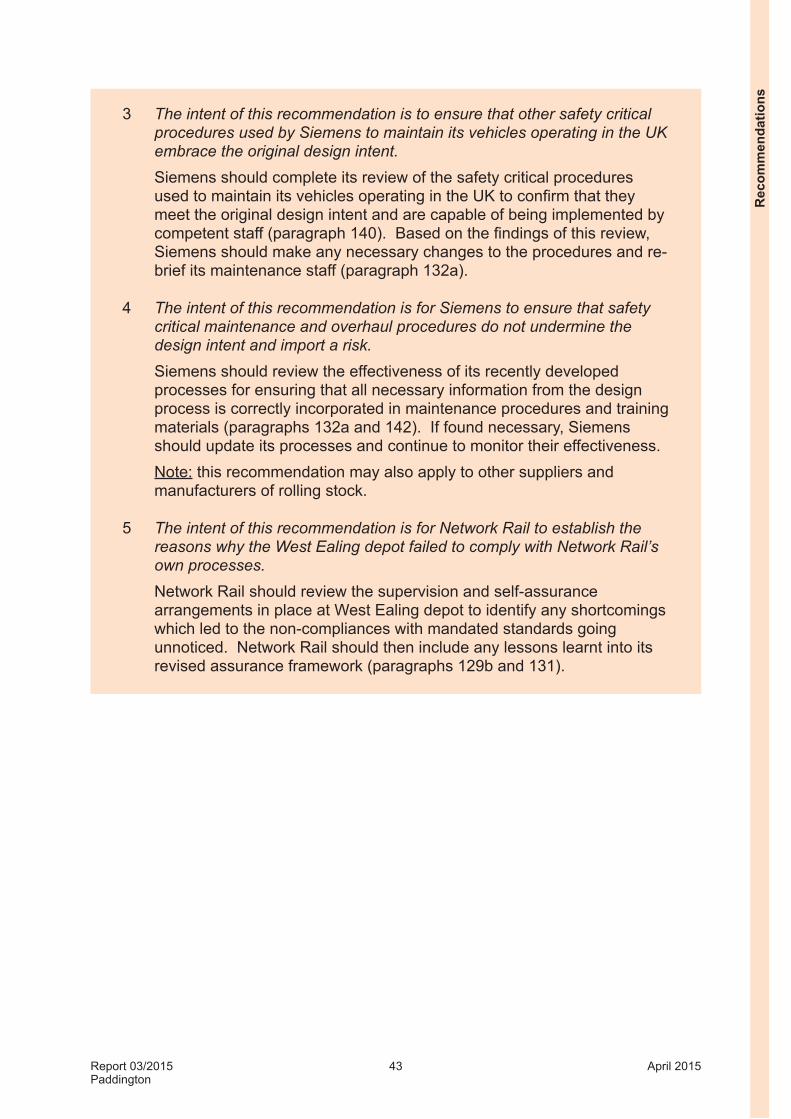
Report 03/2015Paddington
43 April 2015
3 The intent of this recommendation is to ensure that other safety critical procedures used by Siemens to maintain its vehicles operating in the UK embrace the original design intent.
Siemens should complete its review of the safety critical procedures used to maintain its vehicles operating in the UK to confirm that they meet the original design intent and are capable of being implemented by competent staff (paragraph 140). Based on the findings of this review, Siemens should make any necessary changes to the procedures and re-brief its maintenance staff (paragraph 132a).
4 The intent of this recommendation is for Siemens to ensure that safety critical maintenance and overhaul procedures do not undermine the design intent and import a risk.
Siemens should review the effectiveness of its recently developed processes for ensuring that all necessary information from the design process is correctly incorporated in maintenance procedures and training materials (paragraphs 132a and 142). If found necessary, Siemens should update its processes and continue to monitor their effectiveness. Note: this recommendation may also apply to other suppliers and manufacturers of rolling stock.
5 The intent of this recommendation is for Network Rail to establish the reasons why the West Ealing depot failed to comply with Network Rail’s own processes.
Network Rail should review the supervision and self-assurance arrangements in place at West Ealing depot to identify any shortcomings which led to the non-compliances with mandated standards going unnoticed. Network Rail should then include any lessons learnt into its revised assurance framework (paragraphs 129b and 131).
Rec
omm
enda
tions

Report 03/2015Paddington
44 April 2015
Appendices
Appendix A - Glossary of abbreviations and acronymsCCTV Closed circuit television
CMS Competence management system
DMOS2 Driving motor open standard 2
NCR Non-conformance report
OTDR On-train data recorder
PTT Post-tyre turning
SCA Safety critical assessment
SM(T) Section manager (track)
TME Track Maintenance Engineer
TOS2 Trailer open standard 2
VBT Vehicle basic training
Appendices

Report 03/2015Paddington
45 April 2015
Appendix B - Glossary of termsAll definitions marked with an asterisk, thus (*), have been taken from Ellis’s British Railway Engineering Encyclopaedia © Iain Ellis. www.iainellis.com.
Adhesion The friction produced between a rail and a rail wheel.
Alignment check In the context of this report, a set of measurements to confirm that the carbody is straight and flat.
Amber trolley A light trolley manufactured by Geismar pushed along the track to measure the track gauge and cross-level.
Auxiliary reservoir A pressure vessel fitted to rail vehicle, which stores compressed air to supply in this context the secondary suspension when required.
Axlebox The axle bearing housing which connects the wheelset to a rail vehicle via the primary suspension. There is one axlebox at each end of a wheelset.*
Basic visual inspection
A visual inspection of the track, carried out on foot, which aims to identify any immediate or short term actions that are required. Often referred to as a track patrol.
Bogie An assembly of two wheelsets in a frame which is pivoted at the end of a long vehicle to enable the vehicle to go round curves.
Bogie press A press used to mimic the loads imposed on a bogie by a carbody and to settle the suspension so that no further adjustment is needed when the carbody is fitted.
Bogie rotational resistance
A measure of the torque needed to rotate the bogie under the carbody around its vertical axis.
Bolster The transverse member between the bogie frame and carbody underframe (see figure 8). Once assembled, it is an integral part of the carbody.
Buffer stop A device used to stop the progress of rail vehicles at the end of a line.*
Chain(s) A unit of length, being 66 feet or 22 yards (approximately 20.117 metres). There are 80 chains in one standard mile.*
Cross-level The measured difference in level between the two running rails of a track.*
Dynamic track twist The track twist accounting for the voids under the sleepers to correct the cross-levels.
Electric multiple unit
A train consisting of one or more vehicles, semi-permanently coupled together, with a driving cab at each end and whose motive power is electricity supplied externally from overhead line equipment or conductor rails.*
App
endi
ces

Report 03/2015Paddington
46 April 2015
Ellipse A computer based asset management system used by Network Rail to record and prioritise what maintenance is work required to be done and when it needs to be done by.
Engineering Acceptance
The process whereby conformance of railway vehicles to the mandatory requirements of Railway Group standards is scrutinised and certificated.*
Flange The extended portion of a rail wheel that provides it with direction guidance.
Flange contact angle
The angle, relative to the horizontal, of the plane that passes through the point at which the flange (of a rail wheel) contacts the railhead.
Four-foot The space between the rails of a track.
Gauge (of a vehicle)
The maximum permissible dimensions of rail vehicles.
Gauge clearance In the context of this report, it is the size of the gap between a train and a permanent structure.
In-service wheel load measurement system
A system in which both rails on a section of straight and level track are instrumented and measure the load imparted by a moving wheel.*
Intervention limit The threshold value of a defect at which remedial action is required.
Maintenance delivery unit
A Network Rail unit consisting of staff responsible for the maintenance of an area of the railway network.
Maintenance scheduled task
A cyclic inspection or maintenance task which has a frequency prescribed in Network Rail standards and which is scheduled using the Ellipse system.
National safety authority
Under European law, each member state has to establish a safety authority which is independent from railway companies. In the UK, the Office of Rail Regulation is the national safety authority.
Notified body A body given authority to undertake an assessment of compliance with the technical specification for interoperability.
On-train data recorder (OTDR)
A data recorder fitted to a train that records information on the status of train equipment, including speed and brake applications.
Patroller A competent person whose duties are to carry out a basic visual track inspection and minor maintenance.
Appendices
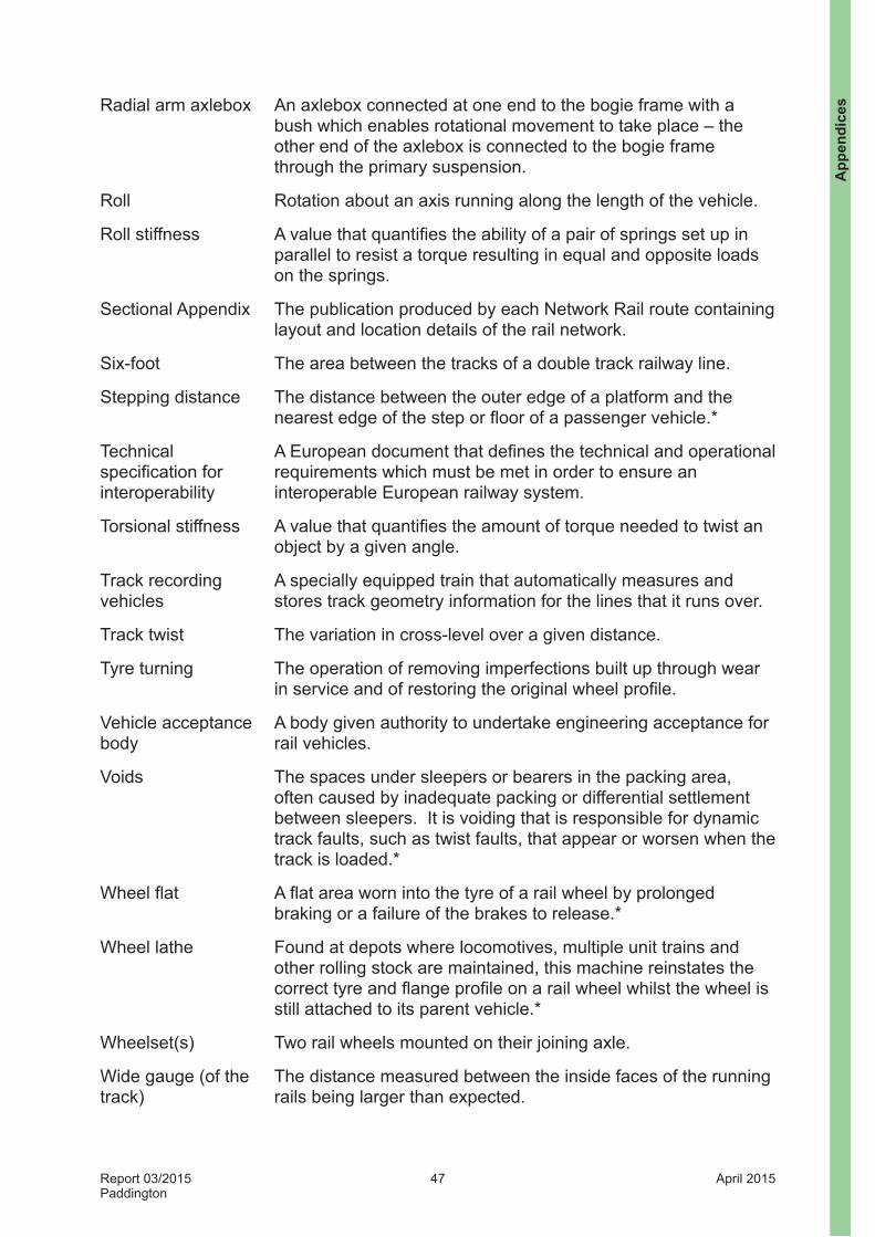
Report 03/2015Paddington
47 April 2015
Radial arm axlebox An axlebox connected at one end to the bogie frame with a bush which enables rotational movement to take place – the other end of the axlebox is connected to the bogie frame through the primary suspension.
Roll Rotation about an axis running along the length of the vehicle.
Roll stiffness A value that quantifies the ability of a pair of springs set up in parallel to resist a torque resulting in equal and opposite loads on the springs.
Sectional Appendix The publication produced by each Network Rail route containing layout and location details of the rail network.
Six-foot The area between the tracks of a double track railway line.
Stepping distance The distance between the outer edge of a platform and the nearest edge of the step or floor of a passenger vehicle.*
Technical specification for interoperability
A European document that defines the technical and operational requirements which must be met in order to ensure an interoperable European railway system.
Torsional stiffness A value that quantifies the amount of torque needed to twist an object by a given angle.
Track recording vehicles
A specially equipped train that automatically measures and stores track geometry information for the lines that it runs over.
Track twist The variation in cross-level over a given distance.
Tyre turning The operation of removing imperfections built up through wear in service and of restoring the original wheel profile.
Vehicle acceptance body
A body given authority to undertake engineering acceptance for rail vehicles.
Voids The spaces under sleepers or bearers in the packing area, often caused by inadequate packing or differential settlement between sleepers. It is voiding that is responsible for dynamic track faults, such as twist faults, that appear or worsen when the track is loaded.*
Wheel flat A flat area worn into the tyre of a rail wheel by prolonged braking or a failure of the brakes to release.*
Wheel lathe Found at depots where locomotives, multiple unit trains and other rolling stock are maintained, this machine reinstates the correct tyre and flange profile on a rail wheel whilst the wheel is still attached to its parent vehicle.*
Wheelset(s) Two rail wheels mounted on their joining axle.
Wide gauge (of the track)
The distance measured between the inside faces of the running rails being larger than expected.
App
endi
ces

Report 03/2015Paddington
48 April 2015
URGENT SAFETY ADVICE
1. INCIDENT DESCRIPTION
LEAD INSPECTOR CONTACT TEL. NO.
INCIDENT REPORT NO
723/01 DATE OF INCIDENT 25/05/2014
INCIDENT NAME London Paddington Station, Platform 3TYPE OF INCIDENT Derailment of empty passenger train
INCIDENT DESCRIPTION
At 05:20 hrs on Sunday 25 May 2014, the third vehicle of an empty five car class 360/2 passenger train manufactured by Siemens and operated by Heathrow Express derailed on its approach to platform 3 at London Paddington station. The train was travelling from Old Oak Common to Paddington in preparation for entering passenger service.
Both sets of wheels on the leading bogie of the third vehicle derailed to the left when the vehicle was about 150 metres from the buffer stops in platform 3 and travelling at between 12 and 14 mph (19.3 and 22.5 km/h). The vehicle derailed on an exit transition following a right hand curve in an area where there was a track twist which, according to Network Rail’s standards, required a repair within 36 hours.
The train ran nearly 100 metres in a derailed state and was finally stopped with the right side of the derailed bogie in a pit that was located between the rails, which lifted both wheels on the left side of the rear bogie off the rails. No one was injured.
Platform 3 remained closed for the remainder of the day.SUPPORTING REFERENCES
Figure 1 The derailed vehicle at Paddington stationFigure 2 Description of the anti-roll bar systemFigure 3 Distance between bogie frame and axlebox
2. URGENT SAFETY ADVICE
USA DATE: 18/06/2014TITLE: Setup of SF5000 bogies and other bogies with similar suspension arrangements
SYSTEM /EQUIPMENT:
Bogie, anti-roll bar
SAFETY ISSUE DESCRIPTION:
Class 360/2 trains are fitted with SF5000 bogies. These bogies have anti-roll bars to react any dynamic roll in the body as a vehicle travels along the track. On each bogie, the anti-roll bar sits inside the bolster and is fitted with an offset connection at both ends (see figure 2).As the body rolls, the offset connection loads the bar inside the bolster in torsion which transfers loads from the body to the bogie frame.
On flat and level track, the anti-roll bars should be set so as not to carry any load. This is checked by the maintainer post-tyre turning or after wheelset replacement as part of Siemens’ procedure for setting the vehicle ride height (Maintenance Procedure No. UOP001). The procedure describes the actions needed if the anti-roll bars are found to be under loadafter setting the correct body height following tyre turning or wheelset replacement. This involves adjusting the length of the links connecting the anti-roll bar to the bogie frame. The procedure also states that the operator should ensure that the links are set to the same length on either side of the bogie.
If the links have been set incorrectly and are of different length, it is possible for the anti-roll bars to permanently carry a load even on flat and level track. This load in the anti-roll bar system will result in the vehicle body loading the bogie frame in a manner which will lead to an uneven wheel load distribution.
Appendix C - Urgent Safety Advice
Appendices

Report 03/2015Paddington
49 April 2015
URGENT SAFETY ADVICE
CIRCUMSTANCES: The RAIB is conducting a full investigation into the incident. As part of this investigation, the unit involved in the derailment was tested with the assistance of the industry parties.
The vehicle that derailed had its tyre turned in April 2014 when Siemens’ procedure UOP001 should have been followed. The other four vehicles in the unit had their wheelsets replaced at the same time. These vehicles would also have been subjected to procedure UOP001.
Post-incident testing on the vehicle that derailed confirmed that the left hand wheels on the leading bogie in the direction of travel at the time of the derailment were significantly lessloaded than the wheels on the right hand side (the load on the left hand side was approximately 3,000 kg per wheel and the load on the right hand side was approximately 5,500 kg per wheel). The trailing bogie on the same vehicle was showing the reversesituation (the load on the left hand side was approximately 5,500 kg per wheel and the load on the right hand side was approximately 3,100 kg per wheel).
Measurements confirmed that the anti-roll bar links were of significantly different length from side to side (approximately 50mm difference on both bogies) and that the links were under load. The uneven settings will have caused the anti-roll bars to carry loads between the body and the bogies, even on flat and level track and appear to be consistent with the uneven load distribution between the wheels on either side of the vehicle.
Further measurements of the distances between the axleboxes and bogie frames (distance Z1 on figure 3) confirmed that the bogie frames were sitting with one side higher than the other one (high on the left hand side and low on the right hand side on the derailed bogie and vice versa on the trailing bogie).
The track twist and the bogie setup both resulted in unloading of the leading left hand wheel of the vehicle and are likely to have combined, possibly with other factors, to cause the derailment.
Post-incident testing on the other vehicles confirmed that the left hand wheels on the leading bogie in the direction of travel on one of the vehicles was significantly more loaded than the wheels on the right hand side (the load on the left hand side was approximately 6,200 kg per wheel and the load on the right hand side was approximately 5,100 kg per wheel). Again the trailing bogie on the same vehicle was showing the reverse situation (the load on the left hand side was approximately 4,700 kg per wheel and the load on the right hand side was approximately 6,100 kg per wheel). Again the anti-roll bars were found to be under-load.
CONSEQUENCES Risk of derailment of passenger vehicles.
App
endi
ces

Report 03/2015Paddington
50 April 2015
URGENT SAFETY ADVICE
REASONS FORISSUE
AND SAFETY ADVICE:
This USA is being issued to raise awareness of these initial bogie-related findings amongowners, operators and maintainers of Siemens Desiro trains, and owners, operators and maintainers of trains with similar bogie design.
The RAIB investigation will include an examination of the methods of bogie setup on Class 360/2 units. It will also assess the condition of the track and the contribution of the track twist that was detected close to the point of derailment.
In the interim we advise that owners, operators and maintainers of Siemens Desiro trains, and owners, operators and maintainers of trains with similar bogie designs to:
gather information on the length of anti-roll bar links on each bogie and how they compare side-to-side;
gather information on the position of the bogie frame in relation to the axleboxes by measuring the distance Z1 (or equivalent) on all corners (see figure 3);
confirm whether anti-roll bars are loaded in the way described in this urgent safety advice; and
establish measures for ensuring that the anti-roll bar links are correctly adjusted so as to avoid uneven wheel loading.
As the data relates to an on-going investigation, the RAIB will need access to this data once it has been collated.
USA SIGN-OFF*INSPECTOR NAME: CI / DCI NAME:
INSPECTOR SIGNATURE: Electronic copy
CI / DCISIGNATURE: Electronic copy
DATE: DATE
Figure 1 Unit 360205 standing at Paddington station immediately after the derailment
Appendices

Report 03/2015Paddington
51 April 2015
URGENT SAFETY ADVICE
Figure 2 Anti-roll bar system
Figure 3 Distance axlebox to bogie frame
Distance Z1
Anti-rollbar link
Offset connection
Anti-roll bar (hidden inside
bolster)
App
endi
ces

Report 03/2015Paddington
52 April 2015
This page is intentionally left blank

This report is published by the Rail Accident Investigation Branch, Department for Transport.
© Crown copyright 2015
Any enquiries about this publication should be sent to:
RAIB Telephone: 01332 253300The Wharf Fax: 01332 253301Stores Road Email: [email protected] UK Website: www.gov.uk/raibDE21 4BA


![MTS Bogie Frame Test System · MTS Bogie Frame Test System Locomotive or passenger car tests [one of the most common standards is UIC 615] requires at least 4-5 actuators of different](https://img.pdfslide.us/doc/110x75/5e86a82558f7f502e224f506/mts-bogie-frame-test-system-mts-bogie-frame-test-system-locomotive-or-passenger.jpg)