Embed Size (px)
Citation preview
Royal Adelaide Hospital General ICU ECMO Guidelines
Authors: Richard Strickland Intensivist Jo Buttery. Nurse Educator Peter Frantzis. Perfusionist October 2009.
1
General ICU ECMO Guidelines
Royal Adelaide Hospital General ICU ECMO Guidelines
Authors: Richard Strickland Intensivist Jo Buttery. Nurse Educator Peter Frantzis. Perfusionist October 2009.
2
This document describes the standardised management of adult patients receiving Extracorporeal Membrane Oxygenation (ECMO) in ICU. Although well established there is very little high grade evidence on which to base recommendations. The information contained within this document is predominantly derived from expert opinion. The RAH would like to thank Dr V. Pelligrino (The Alfred), Mr A Perevolos (The Alfred), Ms E Harris (The Alfred), The Royal Childrens Hospital Melbourne, Liverpool Hospital Sydney, The Rikshospitalet Oslo and the Freeman Hospital Newcastle on Tyne.
Contents
1. Introduction
2. Indications and Contraindications
3. Equipment • Pumps and Circuits • Cannulation trolley • Circuit connections
4. Cannulation
5. Maintenance and staffing
• Circuit management • Respiratory management • Sedation • Anticoagulation • Temperature management • Ward rounds • Nursing care • Weaning
6. Nursing Policies and Procedures
7. Troubleshooting
• V-V ECMO • V-A ECMO
8. Emergency responses
• V-V ECMO • V-A ECMO
9. Changing the Circuit
Royal Adelaide Hospital General ICU ECMO Guidelines
Authors: Richard Strickland Intensivist Jo Buttery. Nurse Educator Peter Frantzis. Perfusionist October 2009.
3
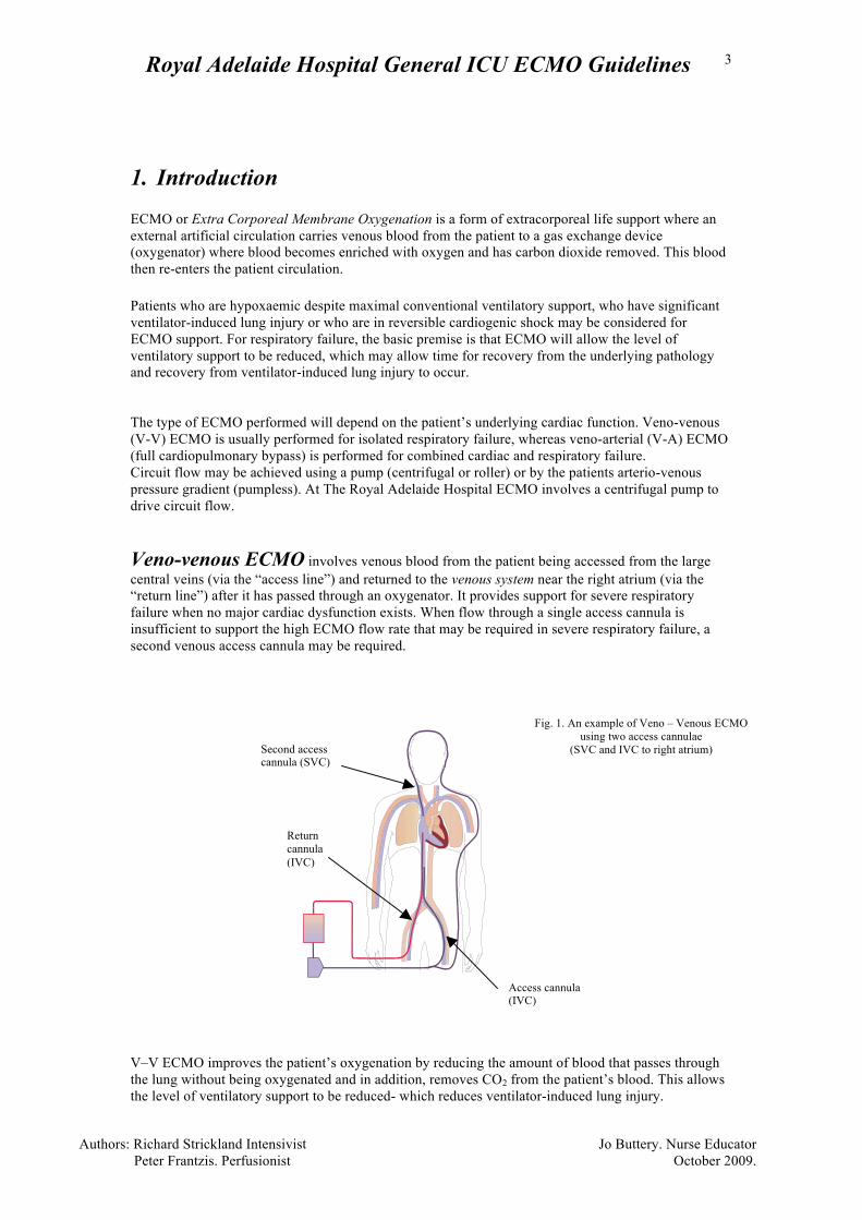
1. Introduction ECMO or Extra Corporeal Membrane Oxygenation is a form of extracorporeal life support where an external artificial circulation carries venous blood from the patient to a gas exchange device (oxygenator) where blood becomes enriched with oxygen and has carbon dioxide removed. This blood then re-enters the patient circulation. Patients who are hypoxaemic despite maximal conventional ventilatory support, who have significant ventilator-induced lung injury or who are in reversible cardiogenic shock may be considered for ECMO support. For respiratory failure, the basic premise is that ECMO will allow the level of ventilatory support to be reduced, which may allow time for recovery from the underlying pathology and recovery from ventilator-induced lung injury to occur. The type of ECMO performed will depend on the patient’s underlying cardiac function. Veno-venous (V-V) ECMO is usually performed for isolated respiratory failure, whereas veno-arterial (V-A) ECMO (full cardiopulmonary bypass) is performed for combined cardiac and respiratory failure. Circuit flow may be achieved using a pump (centrifugal or roller) or by the patients arterio-venous pressure gradient (pumpless). At The Royal Adelaide Hospital ECMO involves a centrifugal pump to drive circuit flow. Veno-venous ECMO involves venous blood from the patient being accessed from the large central veins (via the “access line”) and returned to the venous system near the right atrium (via the “return line”) after it has passed through an oxygenator. It provides support for severe respiratory failure when no major cardiac dysfunction exists. When flow through a single access cannula is insufficient to support the high ECMO flow rate that may be required in severe respiratory failure, a second venous access cannula may be required. V–V ECMO improves the patient’s oxygenation by reducing the amount of blood that passes through the lung without being oxygenated and in addition, removes CO2 from the patient’s blood. This allows the level of ventilatory support to be reduced- which reduces ventilator-induced lung injury.
Fig. 1. An example of Veno – Venous ECMO using two access cannulae
(SVC and IVC to right atrium)
Second access cannula (SVC)
Access cannula (IVC)
Return cannula (IVC)
Royal Adelaide Hospital General ICU ECMO Guidelines
Authors: Richard Strickland Intensivist Jo Buttery. Nurse Educator Peter Frantzis. Perfusionist October 2009.
4
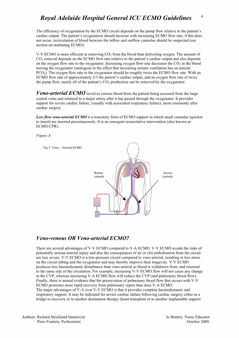
The efficiency of oxygenation by the ECMO circuit depends on the pump flow relative to the patient’s cardiac output. The patient’s oxygenation should increase with increasing ECMO flow rate, if this does not occur, recirculation of blood between the inflow and outflow cannulae should be suspected (see section on instituting ECMO). V-V ECMO is more efficient at removing CO2 from the blood than delivering oxygen. The amount of CO2 removal depends on the ECMO flow rate relative to the patient’s cardiac output and also depends on the oxygen flow rate to the oxygenator. Increasing oxygen flow rate decreases the CO2 in the blood leaving the oxygenator (analogous to the effect that increasing minute ventilation has on arterial PCO2). The oxygen flow rate to the oxygenator should be roughly twice the ECMO flow rate. With an ECMO flow rate of approximately 2/3 the patient’s cardiac output, and an oxygen flow rate of twice the pump flow, nearly all of the patient’s CO2 production can be removed by the oxygenator. Veno-arterial ECMO involves venous blood from the patient being accessed from the large central veins and returned to a major artery after it has passed through the oxygenator. It provides support for severe cardiac failure, (usually with associated respiratory failure), most commonly after cardiac surgery Low flow veno-arterial ECMO is a transitory form of ECMO support in which small cannulae (quicker to insert) are inserted percutaneously. It is an emergent resuscitative intervention (also known as ECMO-CPR). Figure A Veno-venous OR Veno-arterial ECMO? There are several advantages of V-V ECMO compared to V-A ECMO. V-V ECMO avoids the risks of potentially serious arterial injury and also the consequences of air or clot embolisation from the circuit are less severe. V-V ECMO is a low-pressure circuit compared to veno-arterial, resulting in less stress on the circuit tubing and the oxygenator and may thereby improve their longevity. V-V ECMO produces less haemodynamic disturbance than veno-arterial as blood is withdrawn from, and returned to the same side of the circulation. For example, increasing V-V ECMO flow will not cause any change in the CVP, whereas increasing V-A ECMO flow will reduce the CVP (and pulmonary blood flow). Finally, there is animal evidence that the preservation of pulmonary blood flow that occurs with V-V ECMO promotes more rapid recovery from pulmonary sepsis than does V-A ECMO. The major advantages of V-A over V-V ECMO is that it provides complete haemodynamic and respiratory support. It may be indicated for severe cardiac failure following cardiac surgery either as a bridge to recovery or to another destination therapy (heart transplant or to another implantable support
Fig 2. Veno – Arterial ECMO
Access cannula
Return cannula
Royal Adelaide Hospital General ICU ECMO Guidelines
Authors: Richard Strickland Intensivist Jo Buttery. Nurse Educator Peter Frantzis. Perfusionist October 2009.
5
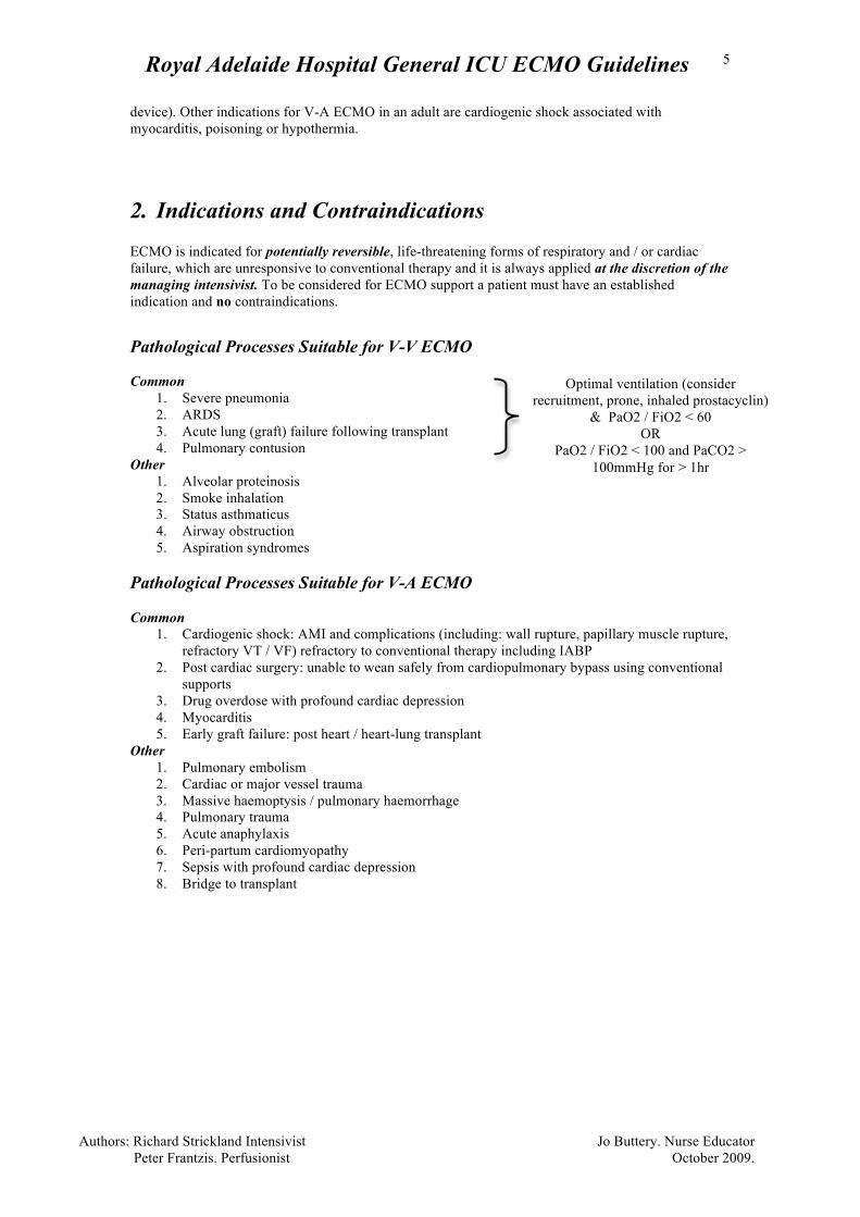
device). Other indications for V-A ECMO in an adult are cardiogenic shock associated with myocarditis, poisoning or hypothermia. 2. Indications and Contraindications ECMO is indicated for potentially reversible, life-threatening forms of respiratory and / or cardiac failure, which are unresponsive to conventional therapy and it is always applied at the discretion of the managing intensivist. To be considered for ECMO support a patient must have an established indication and no contraindications.
Pathological Processes Suitable for V-V ECMO Common
1. Severe pneumonia 2. ARDS 3. Acute lung (graft) failure following transplant 4. Pulmonary contusion
Other 1. Alveolar proteinosis 2. Smoke inhalation 3. Status asthmaticus 4. Airway obstruction 5. Aspiration syndromes
Pathological Processes Suitable for V-A ECMO Common
1. Cardiogenic shock: AMI and complications (including: wall rupture, papillary muscle rupture, refractory VT / VF) refractory to conventional therapy including IABP
2. Post cardiac surgery: unable to wean safely from cardiopulmonary bypass using conventional supports
3. Drug overdose with profound cardiac depression 4. Myocarditis 5. Early graft failure: post heart / heart-lung transplant
Other 1. Pulmonary embolism 2. Cardiac or major vessel trauma 3. Massive haemoptysis / pulmonary haemorrhage 4. Pulmonary trauma 5. Acute anaphylaxis 6. Peri-partum cardiomyopathy 7. Sepsis with profound cardiac depression 8. Bridge to transplant
Optimal ventilation (consider recruitment, prone, inhaled prostacyclin)
& PaO2 / FiO2 < 60 OR
PaO2 / FiO2 < 100 and PaCO2 > 100mmHg for > 1hr
Royal Adelaide Hospital General ICU ECMO Guidelines
Authors: Richard Strickland Intensivist Jo Buttery. Nurse Educator Peter Frantzis. Perfusionist October 2009.
6
Selecting the form of ECMO
1. V-A ECMO: applied for the management of cardio-respiratory failure or cardiac failure where use of a ventricular assist device (VAD) is deemed inappropriate. • Central V-A ECMO: In cases where V-A ECMO is required for cardiac support and
where lung function is poor (large shunt) peripheral V-A ECMO should be avoided. This is because any native cardiac output present will deliver hypoxic blood from the pulmonary veins preferentially to the cerebral circulation (potentially causing severe cerebral hypoxia). Central V-A ECMO is most often employed in patients undergoing cardiac surgery.
• Peripheral V-A ECMO is appropriate when reasonable lung function exists and cardiac surgery is not required
2. Low-flow V-A ECMO (ECMO-CPR) is used only for initial support and stabilisation in emergent conditions requiring V-A support
3. V-V ECMO is used for isolated respiratory failure when adequate heart function for the duration of ECMO is anticipated
4. Hi-flow V-V ECMO is used when circuit flow via a single access cannula is inadequate to maintain safe oxygenation. This may be required if smaller access cannulae have been placed percutaneously (although 25FR percuataneous cannulae have recently become available), in which case a second venous access cannula may be required (eg. from an internal jugular vein).
Royal Adelaide Hospital General ICU ECMO Guidelines
Authors: Richard Strickland Intensivist Jo Buttery. Nurse Educator Peter Frantzis. Perfusionist October 2009.
7
Contraindications Absolute Contraindications to all forms of ECMO
• Age > 65yrs • Non-recoverable cardiac disease • Non-recoverable respiratory disease • Non-recoverable neurological disease • Chronic severe pulmonary hypertension • Active malignancy, graft vs host disease or significant immunosupression
o Post bone marrow, renal, liver transplant or heart/lung transplant beyond 30 days
• Weight > 140 kg • Advanced liver disease • AIDS as defined by:
o Secondary malignancy, prior hepatic or renal (Crt > 250umol/l) impairment or need for salvage anti-retroviral therapy
• Unwitnessed cardiac arrest or CPR > 60min prior to commencement of ECMO (this includes set up - cannulation time)
Relative Contraindications to all forms of ECMO
• Trauma with multiple bleeding sites • Multiple organ failure
Absolute Contraindications to VV ECMO for Respiratory Failure
• Severe pulmonary hypertension (mPAP > 50mmHg) • Severe right or left heart failure (EF< 25%) • Cardiac arrest
Absolute Contraindications to VA ECMO
• Aortic dissection • Severe aortic valve regurgitation
Royal Adelaide Hospital General ICU ECMO Guidelines
Authors: Richard Strickland Intensivist Jo Buttery. Nurse Educator Peter Frantzis. Perfusionist October 2009.
8
3. Equipment
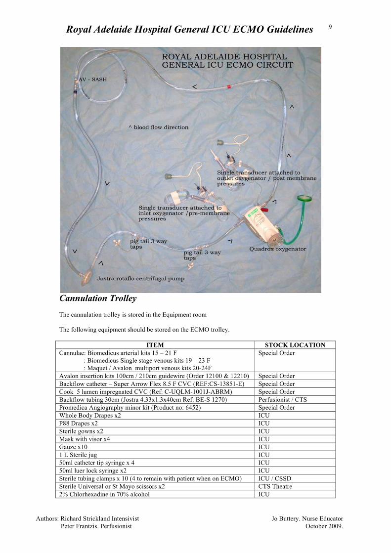
Pumps and Circuits ECMO pumps are stored in the ICU equipment room. Circuits are not stored in ICU but are stored by the Perfusion Service in their pump room. The Perfusion Service should be contacted as soon as possible when a decision is made to initiate ECMO. Out of hours the on call perfusionist should be contacted, the roster is stored on the ECMO trolley or in CT ICU. The perfusionist is responsible for obtaining a pump from the ICU equipment room and priming the circuit. Priming ECMO circuits are primed by the perfusionist. If using a Maquet Prolonged Life Support (PLS) circuit, the priming points from the access line are removed and the access line re joined to the pump head. The excised segment of access line with the priming ports is interposed between the pump head and the oxygenator and secured with cable ties. This is not necessary if using an ‘Alfred’ circuit. The circuit is then flushed with CO2 and primed with heparinised saline according to standard perfusion practice. If time permits the circuit should be coated with albumin. 10cm extension tubing and three way taps will be attached to the access points between the pump and oxygenator. Pre and post oxygenator pressure monitoring requires flush type pressure transducers and sampling manifold be mounted on the arm immediately above the oxygenator and attached via manometer tubing to the luer connectors on the oxygenator. There should be no other connection in the monitoring system or circuit.
Royal Adelaide Hospital General ICU ECMO Guidelines
Authors: Richard Strickland Intensivist Jo Buttery. Nurse Educator Peter Frantzis. Perfusionist October 2009.
9
Cannulation Trolley The cannulation trolley is stored in the Equipment room The following equipment should be stored on the ECMO trolley.
ITEM STOCK LOCATION Cannulae: Biomedicus arterial kits 15 – 21 F : Biomedicus Single stage venous kits 19 – 23 F : Maquet / Avalon multiport venous kits 20-24F
Special Order
Avalon insertion kits 100cm / 210cm guidewire (Order 12100 & 12210) Special Order Backflow catheter – Super Arrow Flex 8.5 F CVC (REF:CS-13851-E) Special Order Cook 5 lumen impregnated CVC (Ref: C-UQLM-1001J-ABRM) Special Order Backflow tubing 30cm (Jostra 4.33x1.3x40cm Ref: BE-S 1270) Perfusionist / CTS Promedica Angiography minor kit (Product no: 6452) Special Order Whole Body Drapes x2 ICU P88 Drapes x2 ICU Sterile gowns x2 ICU Mask with visor x4 ICU Gauze x10 ICU 1 L Sterile jug ICU 50ml catheter tip syringe x 4 ICU 50ml luer lock syringe x2 ICU Sterile tubing clamps x 10 (4 to remain with patient when on ECMO) ICU / CSSD Sterile Universal or St Mayo scissors x2 CTS Theatre 2% Chlorhexadine in 70% alcohol ICU
Royal Adelaide Hospital General ICU ECMO Guidelines
Authors: Richard Strickland Intensivist Jo Buttery. Nurse Educator Peter Frantzis. Perfusionist October 2009.
10
Aqueous Povidionine Iodine ICU 10ml syringes x4 ICU 23G needles x4 ICU 1 L sterile saline ICU Tape to secure cannulae CTS Theatre 1.0 Silk x4 and 2.0 silk x2 ICU Large opsite x4 ICU Roll of Hypafix ICU Duoderm squares x2 ICU Electric razor with spare heads x3 ICU 3 way tap on 10cm extension line (BD Connecta Ref : 394995) x4 Perfusion 30cm monitoring extension line ICU Hi flow 3 way tap (Maquet Ref: BE-PLS 2050)) x3 Perfusionist / CTS 3/8 – 3/8 inch connector and Y connector Perfusionist / CTS B Braun ‘Transofix’ sterile fluid transfer set CTS Heparin 5000u x 5 ICU Haemochron ACT machine and Kaolin ACT tubes Special Order Maquet Rotaflow sensor paste Special order Perfusion on call roster Perfusionist Further items that should remain with the patient: • White board with perfusion and Medical contact numbers • Spare ECMO circuit • 2x single transducer kits • ECMO operating notes, trouble-shooting guide and observation chart • Rota-flow manual • 4 tubing clamps • Rota-flow paste • ACT machine and tubes • 30cm monitoring extension lines for use with CVVHD
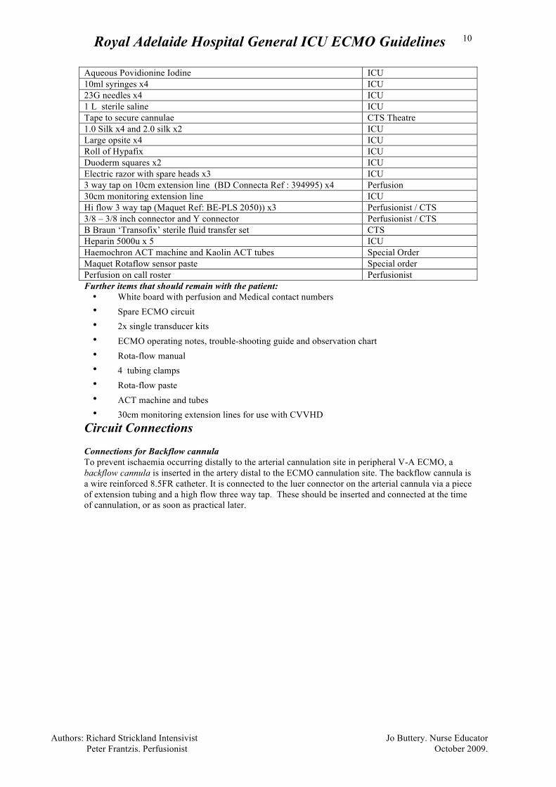
Circuit Connections Connections for Backflow cannula To prevent ischaemia occurring distally to the arterial cannulation site in peripheral V-A ECMO, a backflow cannula is inserted in the artery distal to the ECMO cannulation site. The backflow cannula is a wire reinforced 8.5FR catheter. It is connected to the luer connector on the arterial cannula via a piece of extension tubing and a high flow three way tap. These should be inserted and connected at the time of cannulation, or as soon as practical later.
Royal Adelaide Hospital General ICU ECMO Guidelines
Authors: Richard Strickland Intensivist Jo Buttery. Nurse Educator Peter Frantzis. Perfusionist October 2009.
11
Connections for Continuous Renal Replacement Therapy (CRRT or CVVHD) Ideally, the CVVHD circuit is connected to the ECMO circuit to prevent risk associated with dialysis catheter (e.g. Vascath) insertion. Connecting the CVVHD circuit to the ECMO circuit is usually performed by perfusion staff, although it may be performed by an ICU nurse if they have been trained in this procedure. If the nurse is unsure how to make the connections, they must contact perfusion staff for assistance (this is a high-pressure circuit, opening the taps to air will result in a spray of blood). The commonest way to connect the CVVHD circuit to the ECMO circuit is to attach the access and return lines for CVVHD to the two three-way taps between the outlet of the pump head and the oxygenator. The return line for the CVVHD circuit is connected to the three –way tap closest to the oxygenator and the access line for CVVHD goes to the three-way tap closest to the centrifugal pump. This part of the ECMO circuit (between the pump and the oxygenator) has the highest positive pressure and may interfere with the functioning of the CVVHD (“PRISMA-FLEX”) circuit:
• High CRRT access pressure: If the pressure within the ECMO circuit causes the access pressure in the CVVHD circuit to exceed the alarm limits for access pressure, the dialysis machine (“PRISMA-FLEX”) alarm sounds, and stops CVVHD. To prevent this from occurring select positive access pressures from the set-up menu, then if needed attach at least one 30cm monitoring extension line to the access side of the PRISMA-FLEX, this will lower the pressure and allow the PRISMA-FLEX to function. If the pressure on the access is still too high a second and even a third extension can be added. This may have implications for anticoagulation targets.
• High CVVHD return pressure: If the pressure within the ECMO circuit causes the return
pressure in the CVVHD circuit to exceed the alarm limits for return pressure, the dialysis machine alarm sounds and stops CVVHD. No extension lines should be added to the return side or the CVVHD circuit (this will only increase return pressures). Options to decrease pressure on the return side of the CVVHD circuit:
1. If the ECMO circuit has a backflow cannula: this can be accessed as a return site for the CVVHD circuit. See diagram in section 4.1
2. The CVVHD circuit return blood can be connected to an alternative venous access (eg: appropriate peripheral IV access)
In central ECMO (no backflow cannula) the return line could be attached to a peripheral line. If this is not possible, a Perfusionist may be able to reduce the length of the return line by cutting it and interposing another connector. If there is no alternative, separate dialysis catheter access may be required.
Return Cannula (Arterial)
Tubing to backflow cannula Access Cannula
(Venous)
Royal Adelaide Hospital General ICU ECMO Guidelines
Authors: Richard Strickland Intensivist Jo Buttery. Nurse Educator Peter Frantzis. Perfusionist October 2009.
12
Monitoring of trans-membrane pressures The trans-membrane pressure is derived by subtracting the post- membrane pressure from the pre- membrane pressure. The pre-membrane pressure is measured at a connector near the venous inlet of the oxygenator. The post-membrane pressure is measured at a connector on the oxygenator’s arterial outlet. These connections will be made by the perfusionist. The pressures are displayed on the ICU monitor and the pre and post membrane pressure and trans-membrane pressure should be recorded every 6 hours on the ECMO observation chart. The trans-membrane pressure gradient should be less than 60mmHg, an increase in the pressure drop across the membrane oxygenator can indicate the formation of thrombus within the oxygenator. A steadily increasing trans-membrane pressure without a concomitant increase in the circuit flows is a sign that the oxygenator may need to be replaced.
Royal Adelaide Hospital General ICU ECMO Guidelines
Authors: Richard Strickland Intensivist Jo Buttery. Nurse Educator Peter Frantzis. Perfusionist October 2009.
13
4. Cannulation Cannulation should be performed only by medical specialists who are trained in this procedure. Preparation of the Patient
• New lines should be inserted prior to ECMO cannulation: o arterial line (preferably right radial for peripheral veno-arterial) o long term CVC (5 lumen CVC on trolley) and / or pulmonary artery catheter. Note
right femoral vein is preferable to left for ECMO cannulae. Check CVO2 or SVO2. • A faecal management system should be inserted and sorbitol and flushes charted. • Hair should be clipped from knees to umbilicus (femoral cannulation) and from neck and
scalp if jugular access is required. • If indicated chest drains should be inserted prior to ECMO cannulation • Inotropes and vasopressor infusions made up and connected to patient • Order red blood cells to ensure a “post connection to circuit” Hb of 100g/L (minimum of 2
units immediately available). • Adequate sedation and paralysis • Cannulae selection should be made with the assistance of the cannulae blood flow table. Aim
should be to insert canulae able to capture 70% of cardiac output. • Vein selection, guidewire placement and cannulae positioning should be assisted by
ultrasound and either transthoraic or transoesophageal echocardiography (TOE).
Cannulae Blood Flow Table
Diameter (Fr)
Arterial Catheter
Venous Catheter
15 2.3 1.5 17 3.0 2.0 19 3.9 2.7 21 5.0 3.5 23 6.5 4.5
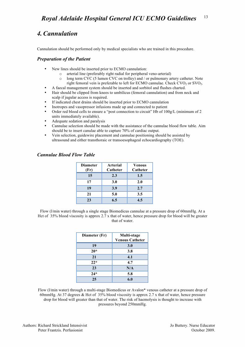
Flow (l/min water) through a single stage Biomedicus cannulae at a pressure drop of 60mmHg. At a
Hct of 35% blood viscosity is approx 2.7 x that of water, hence pressure drop for blood will be greater that of water.
Diameter (Fr) Multi-stage Venous Catheter
19 3.0 20* 3.8 21 4.1
22* 4.7 23 N/A
24* 5.8 25 6.0
Flow (l/min water) through a multi-stage Biomedicus or Avalon* venous catheter at a pressure drop of 60mmHg. At 37 degrees & Hct of 35% blood viscosity is approx 2.7 x that of water, hence pressure
drop for blood will greater than that of water. The risk of haemolysis is thought to increase with pressures beyond 250mmHg.
Royal Adelaide Hospital General ICU ECMO Guidelines
Authors: Richard Strickland Intensivist Jo Buttery. Nurse Educator Peter Frantzis. Perfusionist October 2009.
14
Cannulation
• Percutaneous cannulation is preferable to cut-down, to minimise bleeding from the cannulation sites.
• Decide on cannulation sites (femoral is preferable to jugular). Percutaneous subclavian arterial cannulation (for ECMO) is not performed (but may be performed by surgical cut-down or with a Gore-Tex graft).
• Wash cannulation site with Chlorhexidine (2.0% in 70% alcohol) and wait until dry. • Prepare heparin solution (for heparin locking cannulae and cleaning guidewires): 10,000(u) in
one litre of saline. A sterile 1 litre jug is kept on the cannulation trolley • Move all equipment and monitoring cables so as to allow safe movement of the operator
around the bed. • Full body drapes must be aseptically applied and when IJ cannulation is planned, the bed head
should be draped to the floor. • Medtronic cannulae kits contain all equipment required for insertion of cannulae. Avalon
cannulae require an insertion kit supplied on the trolley. • For peripheral VA ECMO, backflow cannulae should , if possible, be inserted into the femoral
artery percutaneously and heparin-locked prior to ECMO arterial cannula insertion. o An Arrow 8.5F wire-wound cannula is to be used for backflow cannulation of the
femoral artery. This is kept on the cannulation trolley along with a 30cm connection line for attachment to the arterial cannula.
• After successful guide-wire insertion for ECMO cannulae a 70 u/kg bolus of heparin should be given to maintain an ACT of >200. The patient will receive additional heparin as the cannulae are flushed and from the Bioline circuit, hence it is not usually necessary to give larger or repeated doses during cannulation.
• Large skin incisions are to be avoided with percutaneous dilation attempts as this weakens the tightness of the fit around the cannulae once inserted
• In V-A ECMO: the arterial (short) cannula should be fully inserted (to the length of the cannula)
• In V-V ECMO: the return cannula should be positioned in the right atrium with TOE guidance.
• In V-V ECMO: the access cannula should be at the level of the diaphragm (femoral insertion) or in the SVC (internal jugular insertion). Final position will be determined by degree of recirculation and TOE guidance.
• Heparin- lock cannulae immediately after insertion and clamp. Flush regularly if second access is delayed.
• In Hi-flow V-V ECMO: Y-connector should be heparin primed and connected
Commencement of ECMO
• Check ACT and ensure >200 seconds • Ensure oxygen line is connected to oxygenator. Gas flow should be commenced at a rate equal
to or greater than the anticipated circuit blood flow (usually 5-6/min) with 100% O2. • Clean loop is opened and handed to the cannulating physician • The circuit is cut between two clamps allowing sufficient length on the access line and return
line to prevent any tension on the circuit. Note the pump trolley is best kept at the “foot” end of the patient’s bed
• Circuit is connected to cannulae ensuring no air is introduced • Clamps removed as circuit flows are gradually increased • Target flow rates are determined by the cannulating Physician • For V-V ECMO target flows must provide adequate arterial oxygenation • For V-A ECMO target flows must provide adequate oxygen delivery • Check patient and circuit arterial blood gases • Reduce ventilator settings as indicated (see below) • Establish baseline anticoagulation sampling times.
Royal Adelaide Hospital General ICU ECMO Guidelines
Authors: Richard Strickland Intensivist Jo Buttery. Nurse Educator Peter Frantzis. Perfusionist October 2009.
15
Securing Access and Return lines
• Once cannulae position have been confirmed femoral lines should be secured using a two stage prep to the patient’s leg and covering with fabric tape or Hypafix provided on the cannulation trolley as a mesentery dressing. The internal jugular line is directed over the patient’s head. The loop around the head is immobilised by strapping around the patient’s forehead. The cannulae are sutured to the dressing.
Positioning the Pump Head and Oxygenator
• The pump head is kept with outlet at “6 o’clock” to limit bubble transfer • The oxygenator is positioned in the oxygenator arm • The flow sensor should be appropriately coated with ultrasound paste and once in the pump
head covered with Glad-wrap. • Flow sensor zeroing should be performed 30-60min after initiation of ECMO. This requires
transient cessation of circuit flow. This should be performed by the cannulation team once the lines are secure, prior to leaving the patient.
It is the responsibility of the cannulation physician to ensure all cannulae are appropriately positioned and secured, equipment is set and secured up appropriately, flows are optimized and anticoagulation orders completed prior to leaving the patient.
Royal Adelaide Hospital General ICU ECMO Guidelines
Authors: Richard Strickland Intensivist Jo Buttery. Nurse Educator Peter Frantzis. Perfusionist October 2009.
16
5. Maintenance of ECMO and Staffing The ward ICU consultant is the primary Intensivist. The ECMO Intensivist is responsible for all medical decisions involving ECMO while the patient is in ICU and must also be notified of any changes. They can be contacted 24 hours. Whilst on ECMO details of the medical ECMO specialist (Intensivist) and perfusionist on call will be kept by the patient’s bedside. Both will be present during initiation of ECMO. The perfusionist will review the patient with the medical team each morning and again before leaving for the evening. The ECMO Intensivist will review the patient daily and set the ECMO plan in conjunction with the primary Intensivist. Circuit Management In the “ECMO troubleshooting guide” there are algorithms for the management of line problems and the management of unexpected hypoxia and hypercarbia. The Jostra Quadrox D oxygenator is remarkably robust and is capable of several weeks of continuous function. Performance of the oxygenator should be monitored by recording the trans-membrane pressure gradient (the difference in pressure between the inflow and outflow side of the oxygenator) and blood gas analysis of the oxygenator outflow every 12 hours. Circuit change-out is indicated if there is a trend towards increasing transmembrane pressures and / or worsening oxygenator function (oxygenator outflow PaO2 < 150mmHg). A normal transmembrane pressure gradient is <60mmHg. There is no absolute transmembrane pressure value that indicates the need for oxygenator replacement as this value will vary with the flow rate. The decision to change the oxygenator will be based on the trend of transmembrane pressures and oxygenator performance and should also be considered if the ECMO circuit is thought to be a source of sepsis. With V-V ECMO, pre-membrane blood gases may be performed after the initiation of ECMO to identify recirculation of blood between the access and return cannulae. It is not necessary to perform pre-membrane blood gases in patients on V-A ECMO. The Jostra Rotaflow pump is also capable of several weeks of continuous operation. It is important to ensure that the pump RPM rate is not too high for the maximum flow that can be delivered (“over-spinning” the pump). When the maximum pump flow rate has been attained (which is determined by the rate of venous drainage in the access line), increasing the RPM further will increase the negative pressure in the access line, producing ‘line-shake’ and increasing the risk of haemolysis. “Over-spinning” of the pump is corrected by dropping the pump RPM until the flow rate starts to drop. Because the rate of venous drainage in the access line is variable, if the pump RPM is constant and the venous drainage falls (eg. due to decreased preload), the pump will over-spin and access flow limitation will start to occur. Increased noise from the pump head may indicate that it is starting to fail. The other indications for changing the pump head are the development of haemolysis (producing haematuria and an increased plasma free haemoglobin) and large thrombus formation within the pump head. Respiratory management Once adequate ECMO flows have been established and the patient’s oxygenation has improved, the level of ventilatory support is reduced. Typical ventilatory goals would be FiO2 <0.7, Pplt < 30cmH2O, PEEP < 16cmH2O and respiratory rate < 12bpm. In patients on V-V ECMO, reverse diffusion of oxygen may occur if the oxygen tension in the pulmonary artery (due to ECMO and native blood flow) exceeds alveolar pO2. As a rule of thumb, maintaining an FiO2 of 0.5 - 0.6 while the patient is on V-V ECMO should avoid this problem. The commonest respiratory management problem during V-V ECMO arises from the conflicting goals of maintaining adequate oxygenation (which may require a high flow rate) and a low CVP (which is benificial for the lungs, but may cause access limitation of ECMO flow). Hence the goal should be to
Royal Adelaide Hospital General ICU ECMO Guidelines
Authors: Richard Strickland Intensivist Jo Buttery. Nurse Educator Peter Frantzis. Perfusionist October 2009.
17
maintain adequate patient oxygenation at the lowest CVP possible. In practice, an arterial PaO2 of 50-55mmHg or an oxygenation saturation of 85-90% is acceptable. Pushing fluids to maintain a high ECMO flow rate and an oxygen saturation of more than 90% may ultimately result in severe fluid overload. If adequate oxygenation cannot be maintained at a low or normal CVP, a second access line should be inserted. Sedation Deep sedation sufficient to inhibit respiratory movement is required initially. This requires an infusion of midazolam / fentanyl. Tolerance may develop and high doses may be necessary. Addition of ketamine or propofol may be required. In some instances thiopentone infusion is needed. In all patients on high dose opiates a weaning plan should be developed and initiated after cannulae removal. Muscle relaxation may be necessary. In some patients on VV ECMO sedation may be lightened to that needed for endotracheal tube tolerance. This requires an extremely cooperative patient and should only be attempted at the discression and in the presence of the treating ECMO Intensivist. Anticoagulation Although the ECMO circuit has an anticoagulant lining, low-dose heparin is usually administered to prevent clot formation. The lowest effective level of anticoagulation is not known and heparin may be avoided altogether if the risks of heparin therapy are considered excessive. Some patients with severe haemorrhage have safely undergone several days of ECMO without any systemic anticoagulation at all, although in this situation it would be advisable to avoid prolonged periods of low ECMO flow rates (less than 2 lpm). For V-A ECMO following cardiopulmonary bypass, excessive bleeding due to coagulopathy is managed as usual. A note of caution about the use of rFVIIa in patients on ECMO- it has been associated with acute generalised intravascular thrombosis, producing acute circuit failure and death. Following cardiac surgery, heparin is commenced when chest tube drainage is <100ml/h for 2-3hours, the patient is normothermic and coagulation parameters are acceptable. Heparin should ideally be commenced within 24 hours postoperatively and this is usually possible within 12 hours. The dose is titrated to maintain an ACT of 150-180, which should be measured 2nd hourly until it reaches a stable level. Heparin resistance is usually due to ATIII deficiency – this may be treated with fresh frozen plasma. Tranexamic acid may be infused whilst on ECMO. For V-V ECMO, heparin infusion is commenced at 12u/kg/hr once the post cannulation Kaolin ACT has fallen below 200s. Kaolin ACT should be measured 2 hrly for the first 24hrs and heparin infusion adjusted as per the table below. The target Kaolin ACT in patients with platelets > 80000 is 150-180 sec. Anticoagulation in patients with platelet counts < 80000 should be discussed with the ICU consultant, in general heparin would be ceased in these patients. In most instances thrombocytopenia prolongs the ACT, hence this may still be a suitable marked of anticoagulation in mild to moderate thrombocytopenia.
ACT Response < 130 Bolus 1000u and increase infusion 200u/hr.
130 - 150 Increase infusion 100u/hr 150-180 No change 180-200 Decrease infusion 100u/hr 200-250 Decrease infusion 200u/hr
> 250 Cease infusion for 1 hr. Check ACT hourly and recommence when ACT <200s at 300u/hr less
than the original rate. After 24 hours the aPTT is used to monitor anticoagulation (target range of 55-75seconds) as in some patients the aPTT may become excessively prolonged and excessive anticoagulation may occur. aPTT
Royal Adelaide Hospital General ICU ECMO Guidelines
Authors: Richard Strickland Intensivist Jo Buttery. Nurse Educator Peter Frantzis. Perfusionist October 2009.
18
and ACT should be checked 6 hrly and heparin dose adjusted to the APTT as per the hospital protocol. Fibrinogen and d-dimer should be checked daily. Bleeding from around ECMO cannulation sites can be a problem, pressure dressing may be required, as may be blood or factor transfusion and on occasion, surgical exploration may be necessary. Any patient on ECMO must have a current Group and X match and 2 units of blood must be immediately available. The circuitry must be regularly checked for clot formation, which may develop within the pump head and on the inflow side of the oxygenator. Flow below 2 lpm. for prolonged periods must be avoided. Small clots may be seen in the pump head or on the inflow side of the oxygenator. This does not seem to adversely affect oxygenator function and therefore may not necessarily warrant oxygenator change-out. In the past, significant haemolysis occurred due to blood trauma from the centrifugal pump. This appears to occur much less frequently with the Jostra impeller pump although the absolute incidence is not known. Rapidly fluctuating pump flow due to inadequate venous drainage (“line shake” of the access line) may increase the risk of haemolysis, as may the presence of a second access cannula (due to areas of low flow). Plasma-free haemoglobin should be measured twice daily and when clinically indicated. Acceptable values are 0.05-0.1g/l, Care must be taken when collecting and transporting the sample as forceful aspiration of blood or other trauma may produce significant haemolysis. If a valid plasma-free haemoglobin is >0.1g/l, reasons for haemolysis should be sought and corrected and consideration given to changing the pump head. Temperature Management As a heater-cooler is attached to the oxygenator, the patient’s temperature may be regulated. The aim is usually to maintain normothermia but where clinically indicated, mild hypothermia (to 35Cº) may be performed. While the heater cooler is running, the setting on its LED display should be set to about 37C.º The heater-cooler component of the oxygenator may fail after a few days, however this is not usually an indication for changing out the oxygenator as normothermia should be attainable with conventional techniques (Bair Hugger). The heater-cooler settings should only be altered by the perfusion staff unless the nurse has been trained to do this. Should the patient become unexpectedly hypo- or hyperthermic while on ECMO, the ECMO Intensivist on call must be contacted immediately. Ward Rounds and Documentation All ECMO patients should be reviewed on the morning ward round by the primary Intensivist, an ECMO Intensivist and a Perfusionist. Joint decisions about the management plan for that day will be made at this round. • Daily objectives. A list of objectives MUST be detailed on the patient chart by the medical team
each day of ECMO support at each ward round. This specifies o the times routine blood must be taken o sets the daily objectives o the management changes planned o will form part of the medical record
• ECMO observation chart The paper Nursing ECMO Observation chart must be maintained
and reviewed by the rostered medical Perfusionist. Nursing staff can communicate any difficulties with observations with the rostered Perfusionist.
Medical management Investigations required for patients on ECMO include:
• CXR as indicated • Daily bloods: FBE; Ur, Cr, Elect; Mg; PO4; LFT including LDH, APTT, INR, Fibrinogen
Royal Adelaide Hospital General ICU ECMO Guidelines
Authors: Richard Strickland Intensivist Jo Buttery. Nurse Educator Peter Frantzis. Perfusionist October 2009.
19
• APTT is performed 6 hourly as determined by the ECMO Intensivist while the patient is on ECMO.
• The ACT is usually used to titrate heparin in the first 24 hours and is measured 2 hourly over the first day. It is performed by the attending nurse, using 2 mls of arterial or venous blood. A usual target for ACT in the non-bleeding patient with platelet count > 80,000 is 150–180.
• Beyond 24 hours, the APTT performed in the Haematology lab is primarily used to guide heparin therapy. It is performed 4 times per day and is labelled as urgent to ensure safe response times. A usual target for APTT in the non -bleeding patient with platelet count > 80,000 is 55-75.
• Plasma free Hb is performed twice daily and when clinically indicated. The safe range for this is < 0.1g/L. Levels above this MUST be discussed with ECMO Intensivist and Perfusionist.
• Blood cultures daily from the arterial line and as indicated. Do NOT perform venipuncture for the collection of blood cultures.
• Other cultures as indicated
Doppler examination of the blood flow in the back-flow cannula is indicated if deteriorating leg perfusion is observed in the cannulated leg. Antibiotics (vancomycin) to prevent line sepsis are recommended for the duration of ECMO. Other antibiotics are prescribed as indicated. Stress ulcer prophylaxis with iv pantoprazole is recommended No procedure can be performed on a patient on ECMO without the consent of the primary ICU consultant. Protamine is contraindicated for patients on ECMO as it can cause serious circuit related thrombosis Changes to circuit flows are determined by the ECMO Intensivist in discussion with the Perfusionist. Nursing care Nursing education available to further knowledge of ECMO care includes
• ECMO Education Program • Bedside consultation with a medical Perfusionist
Nursing responsibilities are to patient care. Responsibility for technical maintenance of the ECMO circuit lies with the Perfusionists. Patient positioning and the safe performance of pressure area care are affected by ECMO support.
• Patients with ECMO support with an “open sternum” may not be rolled and require alternate means of preventing pressure area care eg: KCI mattress. Patient moves require a Jordan Frame and the presence of medical staff and/or Perfusionist to ensure no change in circuit flows result as a consequence of movement.
• Other patients on ECMO support can be log-rolled and moved for chest x-rays. These moves can be safely performed but require a designated staff member to ensure no tension is transmitted to the cannulae and the circuit tubing is not kinked. This includes patients with surgical grafts for femoral artery access but extra care is required to prevent obstruction to ECMO flow at this site. Moves are scheduled between the hours of 13.00 and 14.00 when double staffing is available and not during the night (unless there is an urgent patient need).
• No elective changes in patient position are to occur between 18.00 – 08.00hrs • All moves are to be performed with medical staff knowledgeable in ECMO immediately
available to assess any circuit changes that may occur. CVVHD connection to the ECMO circuit should be performed by perfusion staff or by a nurse who is trained in this procedure. CVVHD disconnection can be performed by nursing staff. The three- way tap is turned off to the CVVHD circuit and the CVVHD circuit can then be disconnected and a sterile bung applied. The three
Royal Adelaide Hospital General ICU ECMO Guidelines
Authors: Richard Strickland Intensivist Jo Buttery. Nurse Educator Peter Frantzis. Perfusionist October 2009.
20
way tap is NOT to be flushed with any solution including normal saline. Betadine solutions must be used to wipe the connection points when disconnecting the ECMO circuit. No component of the circuit can be cleaned with alcohol containing solutions, as alcohol may damage the circuit tubing. If alcohol containing solutions do contact the circuit, the Perfusionist on call must be immediately notified. Dressings over the cannulation site should be changed if there is significant accumulation of blood beneath the dressing or if the dressing is loose. Dressings should be removed in a toe to head direction to minimize the chance of catheter extraction. Dressing changes should be performed between 08.00 and 18.00hrs. Perfusionists Perfusionists are responsible for the technical support required for all phases of ECMO support. They are in attendance for all cases of ECMO initiation and in the event of patient instability and their contact details should be available at the patient’s bedside. The Perfusionist should attend the morning ward round and review the patient prior to leaving the hospital Monday-Friday. The Perfusionist on –call should also attend the patient Saturday and Sunday, communicating with the primary and ECMO intensivist, preferably at the morning ward round (08.00 – 09.00hrs) Circuit blood gases from the post-membrane pressure line should be taken twice a day and additionally as determined by the Perfusionist. Transports out of ICU are supervised by the Perfusionist and medical staff. All non-emergent transports are performed “in hours” (08.00 – 18.00hrs) Nursing education at scheduled daily visits, to review observations and address nursing concerns related to ECMO Weaning ECMO The decision to wean ECMO is made by the ECMO Intensivist, and in cardio-thoracic patients, it is made in conjunction with cardiac surgeons. The principals of V-A ECMO weaning:
• A period of prolonged low flow (~1 lpm.) is advisable while native heart function is carefully assessed (TOE). As this increases the risk of stasis and clotting within the circuit, additional heparin is required to increase the ACT of about 400s.
• If respiratory function is a concern, it is possible to turn off gas flow to the oxygenator (only at circuit flows ≤1.5L/min) and assess oxygenation achieved using the ventilator exclusively. Note: in this situation the circuit flow acts as a right-to-left shunt. If adequate oxygenation and CO2 removal can be maintained in the presence of this shunt it is likely that respiratory failure can be managed without ECMO.
Principals of V-V ECMO weaning:
• Circuit flow need not be reduced at any stage. Full ventilation is re-established, then the oxygen flow to the oxygenator is turned off and clamped (as oxygen can leak around the flowmeter even when appears to be off). TOE is not required. No additional heparin is required. After 6 hrs of stable native ventilation with adequate gas exchange without oxygenator gas flow consideration may be given to decannulation. Heparin should not be ceased until decannulation, when a small dose of protamine (50-100mg) may be given if required.
Removal of cannulae: Removal of arterial ECMO cannulae should always be removed as an “open” surgical procedure and be accompanied with the vessel wall repair. For removal of venous cannula, a purse –string suture is inserted around the cannulation site and local pressure then applied for 20 minutes.
Royal Adelaide Hospital General ICU ECMO Guidelines
Authors: Richard Strickland Intensivist Jo Buttery. Nurse Educator Peter Frantzis. Perfusionist October 2009.
21
Post-decannulation Doppler: Lower limb venous Doppler studies should be performed following decannulation as prolonged femoral venous cannulation promotes distal DVT formation.
Nursing Management; ECMO The patient care nurse should be someone trained or experienced in ECMO management. Nursing Responsibilities Prior to cannula insertion Assist with the insertion of new lines and infusions, CVC, Arterial lines etc. Remove old lines and non-essential peripheral cannula Insert FMS Insert core temp probe Prepare and position patient Secure ET so access can be maintained during the procedure
Ensure emergency equipment is in close proximity and supplemental fluid is prepared and readily available
Configure monitor with 2 extra pressure cables, labelled UVP, pre and UAP, post. Cannulation Prepare necessary equipment on ECMO Cannulation trolley as guided by medical staff. Scrub and assist with cannulation. Post Cannulation Care Routine observation and documentation of vital signs
o Systolic BP o MAP o Heart Rate o Sa O2 o Pulsatility V/A ECMO.
Hourly assessment
o Neuro Vascular observations of cannulated limbs o ET CO2 o Routine ventilation observations o Urine output. o Core temperature
Circuit Observations Hourly
o Insertion site/ dressing security o Integrity of the circuit o Pump flow (L/min) o FiO2 o Pump Speed (RPM) o Fresh Gas Flow o Functioning of the Heat Exchanger o Assess access line for movement/kicking • Colour of access blood in V/V ECMO
Circuit Observations 4 hourly
Royal Adelaide Hospital General ICU ECMO Guidelines
Authors: Richard Strickland Intensivist Jo Buttery. Nurse Educator Peter Frantzis. Perfusionist October 2009.
22
• Assess for clot formation, lines, pumps and oxygenator, look closely at any
connectors within the circuit. • Assess and record pre/post oxygenator pressures. Record the gradient. Inform MO if
gradient is > 60mmHg • Complete the ‘Rotaflow Pump Checklist’ each shift.
Bloods
Pre and post oxygenator bloods will be taken by the Perfusionists. All other bloods should be taken via the arterial line Anticoagulation For the first 12-24 hrs the Kaolin ACT should be checked every 2 hrs. It is important to have the correct technique when performing this test, if uncertain please ask the Perfusionist for assistance. In brief:
o The ACT should be promptly undertaken following blood aspiration. o Fill the ACT with exactly 2mls of blood, mix by turning the tube end to end 6 times. o Activate machine. o Insert tube into the appropriate test well. Ensure the machine has detected the
sample, the green detector light is on and the tube is turning. The tube may require some gentle manipulation for the sample to be detected.
The target ACT is 150 – 180 sec in patients with platelet counts > 80000. Heparin should be adjusted according to the guidelines in the anticoagulation section. If the platelet count is <80000 or there are other contraindications to anticoagulation the ECMO Intensivist may alter the target ACT, change or cease anticoagulation. After 24 hours and when the ACT is stable anticoagulation is guided by aPTT performed in the lab. The target aPTT is 55-75 unless altered by the ECMO Intensivist. This should be checked every 6 hrs.
Plasma Free Hb (green top) BD with APTT samples, target <0.1 g/L. The blood should be taken through the arterial line. It should be gently and slowly aspirated to prevent false haemolysis of the sample, do not use vacuette. The sample should be gently taken by hand to the laboratory.
Routine Daily Bloods U&E / Mg/ LFT/ FBC should be taken BD to monitor Hb and platelet counts. Venopuncture should be avoided at all times. Blood cultures Are sent daily from the arterial line, if cultures thorough the circuit are required the perfusionists will undertake the procedure. Do not use alcohol on the circuit as it can damage the circuit integrity. Sterilisation of access points should be undertaken with betadine. Cross Match the patient should have a current cross match at all times. (cross match lasts for 72 hours).
Royal Adelaide Hospital General ICU ECMO Guidelines
Authors: Richard Strickland Intensivist Jo Buttery. Nurse Educator Peter Frantzis. Perfusionist October 2009.
23
Other Care
Patient
Sedation levels, as prescribed. Assessment of sedation requirements should be directed by the need to maintain cannula and circuit integrity.
3/24 Neurological observations
3/24 CVP
General Nursing Care
Pressure area care is to be undertaken with an extra staff member designated to monitor the tubing and circuit, ensuring there is no kinking or tension. This should only be undertaken when medical personnel are readily available to manage circuit/flow or oxygenation problems. Turning should be timed, where possible, for the early/late shift overlap where double staff are present to assist. Nocturnal turning, 18.00 – 08.00hrs, should be avoided unless it is essential.
Positioning for the puffy patient
Cannula dressings must be undertaken by 2 nurses with 1 person responsible for cannula security. This should only be undertaken when there are medical personnel present to manage accidental cannula dislodgement (between 08.00hrs and 18.00hrs). Always pull the dressing off towards the insertion site to minimise the risk of cannula displacement Minimise procedures which may cause bleeding, avoid traumatising tissue during mouth care, suction, pressure area and hygiene care. Use mouth swabs, or soft toothbrushes, for mouth care. Do not shave with wet razor. Use electric razor or clippers. Do not dislodge clots on wounds or cannula insertion sites. Have a supply of haemostatic dressings for use when required. Minimise the number of personnel surrounding the patient to those essential for the person’s care and management. Ensure there are medical orders for base line rest ventilation and also for rescue ventilation if ECMO suddenly needs to be abruptly discontinued.
Shift Check
Use Maquet Jostra-Rotaflow Pump Checklist Position pump, oxygenator and tubing to minimise potential knocks and unintended contact.
Alarms Low flow set within .5L of current flow High/Low rev limit set within 500 rpm of current revs
Rev mode Check battery/ connection to AC power/ red power point with LED on Check Gas blender is securely connected to gas flow. Ensure all connection points in the circuit are secure Re-check the above following patient movement.
ENSURE THERE ARE ALWAYS 4 LARGE TUBING CLAMPS LOCATED WITH NEAR THE CIRCUIT TO RAPIDLY STOP THE PUMP IN EMERGENCY SITUATIONS. Hand crank is available Battery is charging or charged
Royal Adelaide Hospital General ICU ECMO Guidelines
Authors: Richard Strickland Intensivist Jo Buttery. Nurse Educator Peter Frantzis. Perfusionist October 2009.
24
Ensure rescue ventilation orders are attached to the ventilator.
CRRT
CRRT can be run through the circuit when the patient’s condition warrants its application. The CRRT circuit should not added before the pump as this part of the circuit is running under negative pressure and adding sidelines will increase the risk of introducing air emboli. Ideally the circuit will be attached between the pump head and the oxygenator through 2 pigtail connectors attached to an inline adaptor, this will be done by the Perfusionist. The CRRT access cannula should be attached to the connector closest to the Pump head and the return to the one closet to the oxygenator. The Prismaflex will be run under positive pressure and the machine must be confirmed that it is being run in this mode If access pressures are too positive for the alarms on the Prismaflex the Prefusionists can add extension tubing to the circuit. This will reduce the pressure and should enable the machine to run. If the return pressures are too positive for the alarms on the Prismaflex the Perfusionists may be able to reduce the length of the tubing and reduce the pressure. If this cannot be done another venous access is necessary. See notes on CVVHDF section. There is no need to add the heating line to the Prismaflex as the blood is heated when is passes through the oxygenator.
Jo Buttery (A) NEF
Royal Adelaide Hospital General ICU ECMO Guidelines
Authors: Richard Strickland Intensivist Jo Buttery. Nurse Educator Peter Frantzis. Perfusionist October 2009.
25
ECMO Troubleshooting VENO-VENOUS ECMO Worsening hypoxia Causes:
• Decreased circuit flows • Increased Cardiac Output (increasing the shunt from the ECMO circuit) • Recirculation of returned oxygenated blood into the access line • Decreased FiO2 • Oxygenator failure • Gas tubing leak or disconnection
Ensure: • Pump flow is adequate (> 2/3 cardiac output) • 100% oxygen is being supplied to the oxygenator • Oxygenator is functioning correctly (outflow pO2 > 150mmHg) • Recirculation minimized (see below)
Consider: Increasing pump flow / increasing ventilation / cooling patient to 35ºC. These changes MUST NOT be performed without the approval of the ECMO Intensivist or medical Perfusionist on-call. Worsening hypercarbia Causes
• Decreased gas flow • Oxygenator failure
Ensure: • Pump flow is adequate (>2/3 cardiac output) • Oxygen flow to oxygenator is at least twice the pump flow rate
Consider: Increasing ECMO flow rate / increasing ventilation /cooling patient to 35ºC Low Flows Causes
• Hypovolaemia (look for a kicking access line) • Clot in oxygenator (look for increased transmembrane pressures) • Kinked tubing • Catheter against vessel wall • Clot in access line
Action • Give fluid, monitor CVP • Reposition tubing • Assess for clot formation and inform ECMO Intensivist and Perfusionist.
Increasing flow rate does not improve oxygenation Ensure recirculation is not occurring: If the access and return cannulae are too close together, recirculation of blood may occur between them (oxygenated blood is drawn down the access cannula). Hence increasing ECMO flow may not improve the patient’s oxygenation. To diagnose recirculation, take a blood gas from the venous side of the oxygenator. This should have a venous pO2. If the pO2 is higher than the patient’s venous pO2, reposition (withdraw) the access line. Consider adding a second access access line via a Y-connector.
Royal Adelaide Hospital General ICU ECMO Guidelines
Authors: Richard Strickland Intensivist Jo Buttery. Nurse Educator Peter Frantzis. Perfusionist October 2009.
26
VENO-ARTERIAL ECMO Worsening hypoxia
Differential hypoxaemia (lower pO2 in the upper body compared to the lower body) can occur during peripheral veno-arterial ECMO when there is severe respiratory failure combined with a high cardiac output. In this situation, the heart is supplying the upper body with de-oxygenated blood, while the ECMO circuit supplies the lower body with oxygenated blood. To detect this problem, patient blood gases should be sampled as close to the heart as possible (hence a right radial arterial line is preferable to a left radial line). Similarly, monitoring of the oxygen saturation of the upper body should be performed with a pulse oximeter on the right hand or with a transcutaneous oximeter attached to the patient’s forehead. To treat differential hypoxaemia, the following steps may be necessary: • Ensure the oxygenator is functioning correctly (return line pO2 > 150mmHg) • Ensure the ECMO flow is as high as possible (within constraints of return line pressure) • Increasing the patient’s ventilation/ PEEP / FiO2 • Consider central cannulation or return via subclavian gortex graft
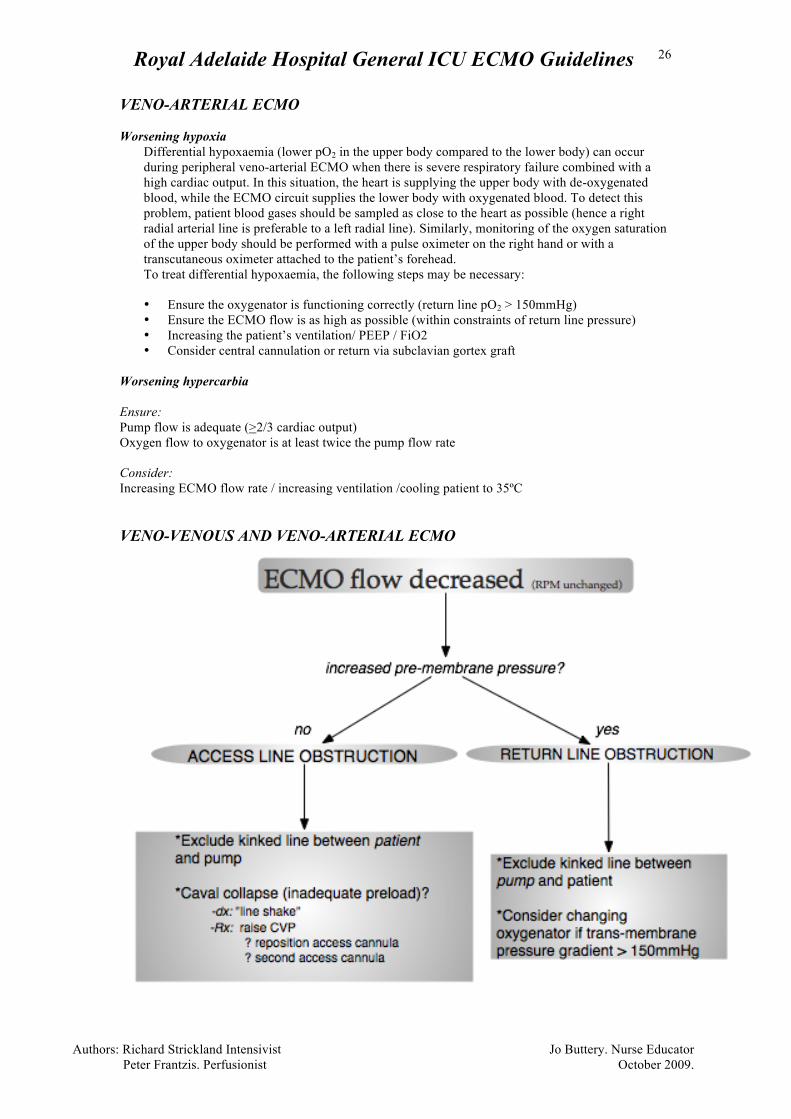
Worsening hypercarbia Ensure: Pump flow is adequate (>2/3 cardiac output) Oxygen flow to oxygenator is at least twice the pump flow rate Consider: Increasing ECMO flow rate / increasing ventilation /cooling patient to 35ºC VENO-VENOUS AND VENO-ARTERIAL ECMO
Royal Adelaide Hospital General ICU ECMO Guidelines
Authors: Richard Strickland Intensivist Jo Buttery. Nurse Educator Peter Frantzis. Perfusionist October 2009.
27
“SIG” alarm on pump console This alarm may occur on the Jostra pump console. The flow rate indicator on the pump says “SIG” while the pump is still functioning normally (RPM rate unchanged). The pump continues to function normally, although flow rate is not displayed. This occurs when the cream that is applied to the flow sensor (under the black clip at the outlet of the centrifugal Jostra pump) has dried out and needs to be replaced. This may be prevented by wrapping the flow sensor in cling-wrap whenever the Rotafow pump is used.
Response: Assess patient saturation and perfusion. If unchanged this is not a critical situation. In hours
contact the Perfusionist or ECMO Intensivist, then if trained in the procedure re-apply ultrasound gel
to the sensor as below:
• Stop pump slowly and clamp inflow and outflow lines to the centrifugal pump.
• Unclip the black clip on the flow sensor and remove the pump head. • Re-apply silicone cream to flow sensor. • Unclamp lines and slowly increase flow back to normal level.
After hours defer the re-application of gel to 08.00h
Royal Adelaide Hospital General ICU ECMO Guidelines
Authors: Richard Strickland Intensivist Jo Buttery. Nurse Educator Peter Frantzis. Perfusionist October 2009.
28
ECMO Complications Haemolysis If haemolysis is suspected while on ECMO, the following steps should be taken: Plasma free-haemoglobin testing: Samples are taken carefully and very slowly through the shortest and widest available sampling port (preferably venous). Samples are labelled as urgent and must be hand delivered to the lab to avoid shaking that will falsely raise the plasma free-haemoglobin. Normal operating plasma free-haemoglobin level is <0.1 g/L. A confirmed plasma free-haemoglobin at or above 0.1 or any high reading associated with clinical evidence of intravascular haemolysis (see below) or circuit malfunction (such as “access insufficiency”) demands a rapid response and must be communicated to perfusion services and the ICU Consultant urgently. Elevated plasma free-haemoglobin readings: Any elevated readings should be re-checked immediately with a repeat sample from a venous port (NOT a stab) and handled meticulously. Repeatedly high readings are confirmation of intravascular haemolysis. Causes are:
• Clot within the circuit or near the cannulae orifices; • Inadequate venous return (poor circulation) • Inappropriate pump speed settings
Signs of haemolysis: Red (or dark brown in extreme cases) urine; high potassium; renal failure; jaundice (late sign). Signs of access insufficiency: Access insufficiency occurs when flow into the circuit from the patient is inadequate for the pump speed settings. This may occur if the venous return is insufficient or there is obstruction near the inlet of the cannulae. Blood flow into the circuit becomes episodic and pressure swings can be very large resulting in damage to red blood cells. The access line tubing may visibly shake or have a palpable “kick”. Continuous, hourly observation of the access line is part of routine nursing care of a patient on ECMO. Management of haemolysis may include:
• Increase volume state and review pump settings (if signs of access insufficiency present) • TOE to ensure cannula not obstructed • Consider changing the circuit • Reset anticoagulation targets
Royal Adelaide Hospital General ICU ECMO Guidelines
Authors: Richard Strickland Intensivist Jo Buttery. Nurse Educator Peter Frantzis. Perfusionist October 2009.
29
Emergency Complications with ECMO Care Emergency complications are dramatic, life threatening changes involving the ECMO circuit that demand immediate responses. They are largely preventable: see accompanying section: The responses required for a range of possible (but extremely rare) emergency complications in patient requiring veno- arterial and veno-venous ECMO are given in the accompanying section:
• Emergency ECMO Responses: Veno-venous ECMO • Emergency ECMO Responses: Veno-arterial ECMO
EmergencyECMOResponses:Veno‐VenousECMO
Emergency ECMO responses are fortunately rare. In general these
complications are almost entirely preventable.
Possible complications are:
Pump Failure Decannulation Circuit Rupture Air Embolism Cardiac Arrest Oxygenator Failure
Royal Adelaide Hospital General ICU ECMO Guidelines
Authors: Richard Strickland Intensivist Jo Buttery. Nurse Educator Peter Frantzis. Perfusionist October 2009.
30
Pump failure (Veno – Venous Response) Definition:
• This is a no flow state due to failure of the electrical pump to drive pump head.
Effects:
• Hypoxia / hypercarbia
• Haemodynamic collapse may occur as a result of severe hypoxia.
Causes:
• Pump head disengagement: eg. accidental contact with pump-head or incorrect initial
placement of pump head or pump head adaptor
• Electrical motor failure
• Battery failure (no AC power connected)
Prevention:
• Always maintain the pump head in a position to minimise the risk of contact especially with
devices such as portable x-ray, haemofilter and Echo
• Minimise time on battery
• Ensure AC “Power Off” alarm is turned on when using wall power
• Console not in use, needs to be plugged into AC power and “on Switch” turned on in order to
recharge battery
Response:
• Re-establish rescue ventilation with 100% oxygen
• Call for help. Contact perfusion services
• Examine circuit: identify pump head disengagement; exclude torsion, kinking or
compression of tubing
• Pump head disengagement
1. Clamp line (anywhere on ECMO circuit) and turn off pump
2. Re-engage pump head
3. Turn pump on to 1000 rpm and remove clamp
4. Gradually increase rpm to previous setting
• Electrical motor failure
1. Clamp line (anywhere on ECMO circuit) and turn off pump
2. Commence manual cranking whilst obtaining spare blood pump (console)
2. Re-engage pump head in new blood pump
3. Turn on blood pump to 1000 rpm and remove clamp
4. Gradually increase revs to previous settings
• Battery failure:
1. Commence manual cranking
2. Re-establish AC power – check
Wall connection – (UPS source)
Circuit breaker and plug at base of ECMO trolley
Power cord connection to pump console
NOTE: If ECMO is off for any period of time, clotting in the circuit is a possibility
Royal Adelaide Hospital General ICU ECMO Guidelines
Authors: Richard Strickland Intensivist Jo Buttery. Nurse Educator Peter Frantzis. Perfusionist October 2009.
31
Decannulation (Veno – Venous Response) Definition:
• This is the removal of either the access or return cannula
Effect:
• Hypoxaemia
• Haemodynamic collapse and hypoxaemia of varying severity (depending on underlying
cardiac and respiratory reserve)
• In central cannulation, right atrial and vena caval damage resulting in catastrophic blood loss
• In peripheral cannulation, massive blood loss from cannulation site
Causes:
• Extreme tension being placed on tubing and hence cannulae and cannulation sites
Prevention:
• Anchoring the cannulae to the patient
• Use of a spotter to ensure that lines remain free during patient manoeuvres
Response:
• Clamp the circuit proximal to the disconnected cannulae and apply pressure to the cannulation
site
• Call for help
i. Contact ECMO Intensivist, Perfusionist
• Assign roles for concurrent patient and circuit management
Patient Management
• Apply pressure to the cannulation site
• Position patient head down
• Give volume to replace blood loss
• Increase the ventilator settings and inotropes to compensate for loss of support.
Circuit Management
• Turn the pump off
Royal Adelaide Hospital General ICU ECMO Guidelines
Authors: Richard Strickland Intensivist Jo Buttery. Nurse Educator Peter Frantzis. Perfusionist October 2009.
32
Circuit Rupture (Veno – Venous Response) Definition:
• This is the disruption of any part of the circuit
Effects:
• Massive blood loss
• Haemodynamic collapse and hypoxia of varying severity (depending on underlying cardiac
and respiratory reserve)
• Circuit or patient air embolus
Causes:
• Fracture and breakdown of polycarbonate components after being cleaned with alcohol
• Broken three way tap
• Accidental cutting or puncturing of circuit tubing
Prevention:
• Do not allow any part of the circuit to come into contact with alcohol or other organic solvent
such as volatile anaesthetic
• Allocated person to act as “spotter” to ensure that three way taps are not snagged on anything
during patient manoeuvres
• Care with needles and instruments near tubing
Response:
• Clamp the circuit on either side of the circuit disruption
• Call for help.
• Contact Perfusionist and ECMO Intensivist
• Assign roles for concurrent patient and circuit management
• Patient Management
- Establish rescue ventilator settings and increase inotropes to compensate for loss
of support.
- Give volume to replace blood loss
• Circuit Management
- If fractured three way tap: if possible place sterile gloved finger over leak
- Connection change
Royal Adelaide Hospital General ICU ECMO Guidelines
Authors: Richard Strickland Intensivist Jo Buttery. Nurse Educator Peter Frantzis. Perfusionist October 2009.
33
Circuit Air Embolism (Veno – Venous Response) Definition:
• This is the introduction of air into the ECMO circuit.
Effects:
• Introduction of air embolus into the patient
• Massive air embolus into the pump head will de-prime the pump, this will lead to
• Severe hypoxaemia
• Haemodynamic collapse and hypoxaemia of varying severity (depending on underlying
cardiac and respiratory reserve)
Causes:
• Introduction of air into the circuit via a peripheral cannulation site
• Fracture of connector or circuit rupture on the access side of the pump
Prevention:
• Only ECMO trained consultants or cardiac surgeons to perform ECMO cannulation
• Only Perfusionist to manipulate the inlet side of the pump
• Do not allow connectors to come into contact with alcohol or organic solvents
Response:
• Clamp the circuit (anywhere on circuit) and switch off pump to prevent further introduction of
air into the patient
• Call for help.
• Contact Perfusionist and ECMO Intensivist
• Assign roles for concurrent patient and circuit management
Patient Management
• Position patient head down
• Inotropic support to maintain MAP
• Establish rescue ventilation
• Volume load
• For air embolus consider
• aspiration of the right heart using existing lines
• hypothermia to 34°, barbiturates, steroids, mannitol, lignocaine, HBO
Circuit Management (removal of air)
• Clamp arterial return line • Turn pump off • Examine circuit for site of air introduction; seal if possible or replace
If no air on the return side of oxygenator: • Rotate pump head outlet to 12 o’clock. • Ensure air vent on oxygenator is open and attach a 60 ml luer lock syringe to circuit
venting port distal to oxygenator and aspirate air and blood. If pump head is not deprimed, slowly turn on pump, using partial clamp release to help control flow; the air will be vented from the oxygenator provided the flow is low. Aspirate any air distal to oxygenator using 60ml syringe.
• Return pump head to 6 o’clock position.
Royal Adelaide Hospital General ICU ECMO Guidelines
Authors: Richard Strickland Intensivist Jo Buttery. Nurse Educator Peter Frantzis. Perfusionist October 2009.
34
If air on the return side of oxygenator: • Clamp both the return cannula and access line • Attach a 60 ml luer lock syringe to the post oxygenator luer conector. • Whilst aspirating partially release the clamp on the return cannulae to allow blood
flow back down the return line and enable aspiration of air via the luer lock 60ml syringe.
• Once all air is removed from circuit and the site of air entry fixed, remove clamps and
resume ECMO
Royal Adelaide Hospital General ICU ECMO Guidelines
Authors: Richard Strickland Intensivist Jo Buttery. Nurse Educator Peter Frantzis. Perfusionist October 2009.
35
Cardiac Arrest (Veno – Venous Response) Definition:
• This is the cessation of patient’s circulation. ECMO flow will diminish accordingly
Effects:
• Patient will be in cardiac arrest.
Causes:
• Usual causes of cardiac arrest
Prevention:
• Identify risk factors and treat
Response:
• Call for help
• Commence ACLS
• Notify Primary Intensivist, ECMO Intensivist and Perfusionist
• Continue ECMO although reduce ECMO flows if signs of circuit access insufficiency
Royal Adelaide Hospital General ICU ECMO Guidelines
Authors: Richard Strickland Intensivist Jo Buttery. Nurse Educator Peter Frantzis. Perfusionist October 2009.
36
Oxygenator failure (Veno – Venous Response) Definition:
• Gas transfer failure is a gradual process that is identified through routine blood gas
analysis and requires elective responses by perfusion services.
• Sudden causes of oxygenator failure are :
i. Water leak external (heat exchanger rupture)
ii. Water to blood leak
Effects:
• Heat Exchanger Rupture : Water spraying everywhere, loss of ability to control blood
temperature through oxygenator
• Water to Blood Leak : Massive haemolysis and sepsis
Causes:
• Heat Exchanger Rupture
• Excessive water pressure in heat exchanger
• Tension on heater hoses
• Manufacturing defect
Prevention:
• Ensure that no equipment is rolled over or obstructs the heater hoses attached to the
oxygentaor
Response:
• Heat Exchanger Rupture:
• Turn off Heater Unit
• Contact Perfusionist and ECMO Intensivist
• Use warming blanket to control patient temperature
• Water to blood leak (Evident as massive haemolysis / cardiovascular instability)
• Turn off Heater Unit
• Contact ECMO Intensivist and Perfusion
Royal Adelaide Hospital General ICU ECMO Guidelines
Authors: Richard Strickland Intensivist Jo Buttery. Nurse Educator Peter Frantzis. Perfusionist October 2009.
37
Emergency ECMO Responses: Veno-Arterial ECMO
Emergency ECMO responses are fortunately rare. In general these complications are almost entirely preventable. Possible complications are:
Pump Failure
Decannulation
Circuit Rupture
Air Embolism
Cardiac Arrest
Oxygenator Failure
Royal Adelaide Hospital General ICU ECMO Guidelines
Authors: Richard Strickland Intensivist Jo Buttery. Nurse Educator Peter Frantzis. Perfusionist October 2009.
38
Pump failure (Veno – Arterial Response)
Definition:
• This is a no flow state due to failure of the electrical pump to drive pump head.
Effects:
• If the circulation is mainly mechanically driven: this is associated with haemodynamic
collapse • If a significant non-mechanical (native) circulation is present: The ECMO circuit becomes a
passive conduit as it contains no valves or occlusive rollers. Hence reversal of blood flow
(from the aorta to the central veins -along its pressure gradient) will occur, which will reduce
the cardiac output and increase the preload to the right heart. The extent of hypotension and
hypoxia that may result will depend on the underlying cardiac function. Causes:
• Pump head disengagement: eg. accidental contact with pump-head or incorrect initial
placement of pump head or pump head adaptor
• Electrical motor failure
• Battery failure (no AC power connected)
Prevention:
• Always maintain the pump head in a position to minimise the risk of contact especially with
devices such as portable x-ray, haemofilter and TOE
• Minimise time on battery
• Ensure AC “Power Off” alarm is turned on when using wall power
• Console not in use, needs to be plugged into AC power and “on Switch” turned on in order to
recharge battery
Response:
• Clamp lines
• Call for help. Contact Perfusionist and ECMO Intensivist
• Assign roles for concurrent patient and circuit management
Patient Management
• Establish rescue ventilation +/- CPR if haemodynamic collapse
Circuit Management
• Examine circuit: identify power failure, motor failure or pump head disengagement;
exclude torsion, kinking or compression of tubing,
• Pump head disengagement
1. Clamp line (anywhere on ECMO circuit) and turn off pump
2. Re-engage pump head
3. Turn pump on to 1000 rpm and remove clamp
4. Gradually increase rpm to previous setting
• Electrical motor failure
1. Clamp line (anywhere on ECMO circuit) and turn off pump
2. Establish manual cranking whilst obtaining spare blood pump (console)
Royal Adelaide Hospital General ICU ECMO Guidelines
Authors: Richard Strickland Intensivist Jo Buttery. Nurse Educator Peter Frantzis. Perfusionist October 2009.
39
3. Re-engage pump head in new blood pump
4. Turn on blood pump to 1000 rpm and remove clamp.
5. Gradually increase revs to previous settings
• Battery failure:
3. Commence manual cranking
4. Re-establish AC power – check
Wall connection – (UPS source)
Circuit breaker and plug at base of ECMO trolley
Power cord connection to pump console
NOTE: If ECMO is off for any period of time, clotting in the circuit is a possibility
Royal Adelaide Hospital General ICU ECMO Guidelines
Authors: Richard Strickland Intensivist Jo Buttery. Nurse Educator Peter Frantzis. Perfusionist October 2009.
40
Decannulation (Veno – Arterial Response) Definition:
• This is the removal of either the access or return cannula
Effect:
1. Haemodynamic collapse and hypoxia of varying severity (depending on underlying cardiac
and respiratory reserve)
2. In centrally cannulated, immediate loss of ECMO support and:
a. if arterial, cannula would be pulled out of or torn off Aorta resulting in catastrophic
blood loss
b. if venous, cannula would be pulled out of Right Atrium.
3. In peripherally cannulated, massive blood loss from cannulation site (may be controllable)
4. Possible introduction of air into ECMO circuit and patient
Causes:
• Extreme tension being placed on tubing and hence cannulae and cannulation sites
Prevention:
• Anchoring the cannulae to the patient
• Use of a spotter to ensure that lines remain free during patient manoeuvres
Response:
• Clamp the circuit
• Call for help. Contact ECMO Intensivist, Perfusionist and Cardiothoraic surgeon.
• Assign roles for concurrent patient and circuit management
Patient Management
• If peripheral cannulation apply pressure to the cannula site
• Position patient head down
• Give volume to replace blood loss
• Increase the ventilator settings and inotropes to compensate for loss of support.
• If central cannulation
i. prepare for chest opening in ICU
ii. Give fentanyl 500ug iv
Circuit Management
• Turn the pump off
Royal Adelaide Hospital General ICU ECMO Guidelines
Authors: Richard Strickland Intensivist Jo Buttery. Nurse Educator Peter Frantzis. Perfusionist October 2009.
41
Circuit Rupture (Veno – Arterial Response) Definition:
• This is the disruption of any part of the circuit
Effects:
• Massive blood loss
• Haemodynamic collapse and hypoxaemia of varying severity (depending on underlying cardiac
and respiratory reserve)
• Circuit or patient air embolus
Causes:
• Fracture and breakdown of polycarbonate components after being cleaned with alcohol
• Broken three way tap
• Accidental cutting or puncturing of circuit tubing
Prevention:
• Do not allow any part of the circuit to come into contact with alcohol or other organic solvent
such as volatile anaesthetic
• Allocated person to act as “spotter” to ensure that three way taps are not snagged on anything
during patient manoeuvres
• Care with needles and instruments near tubing
Response:
• Clamp the circuit on either side of the circuit disruption
• Call for help. Contact Perfusionist and ECMO Intensivist
• Assign roles for concurrent patient and circuit management
Patient Management:
• Increase the ventilator settings and inotropes to compensate for loss of support.
• Give volume to replace blood loss
Circuit Management:
• If fractured three way tap: if possible place sterile gloved finger over leak
- Connection change
Royal Adelaide Hospital General ICU ECMO Guidelines
Authors: Richard Strickland Intensivist Jo Buttery. Nurse Educator Peter Frantzis. Perfusionist October 2009.
42
Circuit Air Embolism (Veno – Arterial Response) Definition:
• This is the introduction of air into the ECMO circuit.
Effects:
1. Massive air embolus into the pump head will deprime the pump and stop it pumping
leading to haemodynamic collapse and hypoxaemia of varying severity (depending on
underlying cardiac and respiratory reserve)
2. Possible introduction of air embolus into the patient
Causes:
• Introduction of air into the circuit via a peripheral cannulation site
• Fracture of connector on the inlet side of the pump (Vent port on arterial cannulae or Y connector if on
Hi-flow VV)
Prevention:
• Only ECMO trained consultants to perform cannulae insertion
• Only perfusionist to manipulate the inlet side of the pump
• Do not allow connectors to come into contact with alcohol or organic solvent
Response:
• Clamp the circuit (anywhere on circuit)
• Switch off pump to prevent further introduction of air into the patient
• Call for help. Contact Perfusionist and ECMO Intensivist
• Assign roles for concurrent patient and circuit management
• Patient Management
• Position patient head down
• Inotropic support to maintain MAP
• Establish rescue ventilation
• Volume load
• For patient air embouls
• Consider aspiration of the right heart using existing lines (if venous air
embolus via access cannulae. This is unlikley)
• Consider hypothermia to 34°, barbiturates, steroids, mannitol, iv
lignocaine, HBO for air embolus
• Circuit Management (removal of air)
• Clamp arterial return line • Turn pump off • Examine circuit for site of air introduction; seal if possible or replace
If no air on the return side of oxygenator:
• Rotate pump head outlet to 12 o’clock. • Ensure air vent on oxygenator is open and attach a 60 ml luer lock syringe to circuit
venting port distal to oxygenator and aspirate air and blood. If pump head is not deprimed, slowly turn on pump, using partial clamp release to help control flow; the air will be vented from the oxygenator provided the flow is low. Aspirate any air distal to oxygenator using 60ml syringe.
Royal Adelaide Hospital General ICU ECMO Guidelines
Authors: Richard Strickland Intensivist Jo Buttery. Nurse Educator Peter Frantzis. Perfusionist October 2009.
43
• Return pump head to 6 o’clock position.
If air on the return side of oxygenator: • Clamp the arterial return cannula on the patient side of the luer lock port; remove
first clamp. • Attach a 60 ml luer lock syringe to the luer lock port and aspirate air and blood.
• Once all air is removed from circuit, remove clamps and resume ECMO
Royal Adelaide Hospital General ICU ECMO Guidelines
Authors: Richard Strickland Intensivist Jo Buttery. Nurse Educator Peter Frantzis. Perfusionist October 2009.
44
Cardiac Arrest (Veno – Arterial Response) Definition:
• This is the cessation of native cardiac function. Pulseless circulation
Effects:
• Little haemodynamic effect if circuit flow is above 4 L/min
Causes:
• Cardiac stunning
• Hyperkalaemia
• Arrhythmia ie: VF
Prevention:
• Need to exclude reversible factors
Response:
• Establish adequate circuit flow
• Notify Primary and ECMO Itensivist and Perfusionists
• Address reversible factors
• Defibrilate if indicated / consider antiarryhthmics
• Vasopressor if indicated
Royal Adelaide Hospital General ICU ECMO Guidelines
Authors: Richard Strickland Intensivist Jo Buttery. Nurse Educator Peter Frantzis. Perfusionist October 2009.
45
Oxygenator failure (Veno – Arterial Response)
Definition:
• Gas transfer failure is a gradual process that is identified by worsening pO2 values in the
post-membrane blood gases or by an increasing trans-membrane pressure gradient. It
requires an elective response by perfusion services.
• Sudden causes of oxygenator failure are:
• Water leak external (heat exchanger rupture)
• Water to blood leak
Effects:
• Heat Exchanger Rupture: Water spraying everywhere, loss of ability to control blood
temperature through oxygenator
• Water to Blood Leak: Massive haemolysis and sepsis
Causes:
• Heat Exchanger Rupture:
• Excessive water pressure in heat exchanger
• Excess tension on heater hoses
• Manufacturing defect
Prevention:
• Ensure that no equipment is rolled over or obstructs the heater hoses attached to the
oxygentaor
• Avoid excess traction on the heater hoses
Response:
• Heat Exchanger Rupture:
• Turn off Heater Unit
• Contact Perfusionist and ECMO Intensivist
• Use warming blanket to control patient temperature
• Water to blood leak (Evident as massive haemolysis / cardiovascular instability)
• Turn off Heater Unit
• Contact ECMO Intensivist and Perfusion
Royal Adelaide Hospital General ICU ECMO Guidelines
Authors: Richard Strickland Intensivist Jo Buttery. Nurse Educator Peter Frantzis. Perfusionist October 2009.
46
Changing the circuit
Change the whole circuit in the event of either an oxygenator or pump failure. It should take less than 60 seconds to cut and change the tubing. This will usually be performed by the Perfusionist with assistance from ICU. Indications • Increasing transmembrane pressure gradient; it should be <50 mmHg • Oxygenator outflow PaO2 <150 mmHg • Heat exchanger rupture • Increased noise from pump head • Large thrombus formation within pump head • Development of haemolysis
Method • Re-establish full ventilation. • Apply defib pads - (as some patients will arrest due to hypoxia - especially respiratory cases). • Prime the new ECMO circuit, as per the above guidelines in a second pump. • If the new circuit has been primed in the hand crank, remove the pump head from the hand
crank. • Use a four person technique with appropriate PPE and sterile field, scissors and gloves. Prep
the circuit with aqueous betadine, not alcohol. • Position two people on each side, one to cut and change the tubing and one with a 1 L jug of
sterile saline and 4 filled 60ml catheter tipped syringes to fill the circuit as required. • Double-clamp the new patient loop, divide it between the connectors, remove the interposing
tubing to expose the straight ⅜” connectors and prime the connectors with a syringe of saline. • Stop the old pump slowly and double clamp the arterial return and venous access lines close to
the patient (clamp on the coloured tapes, cut between the tapes) • Divide the lines close to the clamps on the side of the clamps away from the patient and prime
their ends using a syringe of saline. • Connect the new lines to the ends of the old lines. If using the same pump, • Disconnect the heater-cooler tubing from the old oxygenator. • Disconnect the fresh gas line from the old oxygenator. whilst the new connections are being made • Remove the old pump head from the pump and insert the new pump head • Connect the fresh gas line to the new oxygenator. • Connect the heater-cooler tubing to the new oxygenator. • Unclamp the lines and slowly increase flow back to normal level. • Apply gun-ties to the new connections in the lines. The blood remaining in the old circuit may be drained into citrate bags for re-infusion, unless there is thrombus in the circuit.
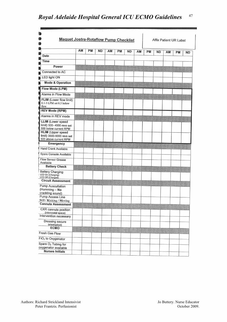
Royal Adelaide Hospital General ICU ECMO Guidelines
Authors: Richard Strickland Intensivist Jo Buttery. Nurse Educator Peter Frantzis. Perfusionist October 2009.
47