Embed Size (px)
Citation preview

ABB Network Partner AB
General
• Complete stator earth-fault protection for unearthed or high impedance earthed generators
• Cost-effective and simple to apply; does not require additional high voltage equipment
• Designed in COMBIFLEX® modular system and equipped with COMBITEST® test switch
• RAGEK 95%
- earth-fault protection covering 95% of the stator winding- two stage measuring of filtered fundamental frequency neutral point voltage- each stage has delayed output with three make contacts and red indicating flag- dimension: 4U 24C
• RAGEK 100%
- earth-fault protection covering 100% of the stator winding- measures filtered fundamental frequency neutral point voltage to protect 95% of the stator winding- measures filtered third harmonic neutral point voltage to protect 95-100% of the stator winding- as little as 1% generator third harmonic voltage enables full protection- delayed outputs with three make contacts and red indicating flag- the 95-100% function is supervised by generator voltage or current- dimension: 4U 42C
RAGEK 100 % and 95 % stator earth-fault protection for generators.
1MRK 504 006-UEN
Version 1August 1997
Replaces
User´s Guide

ABB Network Partner ABRAGEK 100 % and 95 % stator earth-fault protection for generators. Version 1
August 1997
1MRK 504 006-UENPage 2
List of contents1 Application.................................................................................. 3
2 Measurement principles ............................................................ 42.1 Example 1: Generator with neutral point resistor ........................ 52.2 Example 2: Generator without neutral point resistor ................... 7
3 Design .......................................................................................... 83.1 RAEGK 95 % stator earth-fault protection.................................. 83.2 RAEGK 100 % stator earth-fault protection with voltage
supervision ................................................................................... 83.3 RAEGK 100 % stator earth-fault protection with current
supervision ................................................................................... 9
4 Setting........................................................................................ 104.1 95 % relay .................................................................................. 104.2 100 % relay ................................................................................ 104.3 Voltage supervision relay........................................................... 104.4 Current supervision relay ........................................................... 10
5 Technical data .......................................................................... 11
6 Receiving, Handling and Storage ........................................... 136.1 Receiving and Handling............................................................. 136.2 Storage ....................................................................................... 13
7 Installation, Testing and Commissioning............................... 147.1 Installation.................................................................................. 147.2 Testing........................................................................................ 147.3 Commissioning .......................................................................... 14
8 Maintenance ............................................................................. 14
9 Terminal and Circuit diagrams .............................................. 159.1 RAGEK 95% stator E/F protection............................................ 169.2 RAGEK 100% stator E/F protection with voltage supervision . 189.3 RAGEK 100% stator E/F protection with current supervision.. 20
Appendix A: Calculation of generator neutral point voltage in case of an earth-fault in the HV network 22

RAGEK 100 % and 95 % stator earth-fault protection for generators.
ABB Network Partner AB 1MRK 504 006-UENPage 3
Version 1August 1997
1 ApplicationCommon practice in most countries is to earth the generator neutralthrough a resistor. The current through the neutral point resistor will nor-mally be 5 - 10 A when subjected to the rated phase to earth voltage. Forgenerators with step-up transformer, a neutral point voltage relay withtypical setting 5 % of generator phase voltage will provide earth-fault pro-tection for 95 % of the stator winding. It also covers the generator bus,the low-voltage winding of the step-up transformer and other ancillariesgalvanically interconnected with the stator winding.
An earth-fault close to the neutral point of the generator will not give suf-ficient neutral point voltage to activate the neutral point voltage (95 %)relay. Generators which produce about 1 % or more third harmonic volt-age under all service conditions, can have the entire stator winding,including the neutral point, protected using a scheme which combines theneutral point voltage function (95 % relay) and a third harmonic under-voltage function. Under normal service, typically 40 - 60 % of the gener-ated third harmonic phase voltage will appear across the neutral pointresistor and will activate the third harmonic voltage relay. If an earth-faultoccurs close to the neutral point, the third harmonic voltage drops to a lowvalue and the undervoltage relay operates. The relay must have a filterwhich prevents the fundamental frequency neutral point voltage fromaffecting the third harmonic voltage function.
The 100 % stator earth-fault protection can also be used for generatorswith unearthed neutral. The third harmonic voltage between the neutralpoint and earth will increase compared to generators with earthing resistorand the third harmonic undervoltage (100 %) function can cover a largerpart of the stator winding. However, in case of an earth-fault in the highvoltage (HV) network, the zero-sequence voltage transferred to the statorcircuit via the capacitance between the HV and LV windings of the step-up transformer increases compared to generators with neutral point resis-tor. The voltage setting or the time delay of the generator neutral pointvoltage (95 %) relay must then be increased to get selectivity againstearth-fault relays on the HV side.
The 100 % stator earth-fault protection can even be used for generatorswith neutral point tuned reactor. The third harmonic voltage between theneutral point and earth will increase, compared to generators with earth-ing resistor. The zero-sequence voltage transferred to the stator circuit incase of an earth-fault in the HV network will generally be so high thatselectivity of the 95 % relay can not be obtained by a reasonable increaseof the voltage setting.
A generator bus voltage supervision relay is included to prevent unwantedoperation of the third harmonic (100 %) relay when the generator is out ofservice and during running up/down. Alternatively, a stator current super-vision relay is used to block the third harmonic voltage relay until the gen-erator is in service.

ABB Network Partner ABRAGEK 100 % and 95 % stator earth-fault protection for generators. Version 1
August 1997
1MRK 504 006-UENPage 4
The generator should be the only third harmonic voltage source galvani-cally interconnected with the stator circuits. An exception is contra-rotat-ing (twin) generators which always have the same loading and henceproduce the same amount of third harmonic voltage.
2 Measurement principlesIn case of an earth-fault on the stator winding and no additional faultresistance, the fundamental frequency neutral point voltage is increasingin proportion to the distance of the fault from the neutral point. Hence avoltage relay set to 5 % of the stator phase voltage will protect 95 % of thestator winding.
The third harmonic voltage induced in the stator windings has basicallythe same phase angle and same magnitude in all three phases. A closedloop for third harmonic currents is made up by the phase-to-earth capaci-tance and the earthing impedance in the generator neutral. A good repre-sentation of the distributed stator winding capacitance to earth is obtainedby placing one half of the total winding capacitance on the neutral pointside and one half on the terminal side, see Figure 1. The capacitance CLcomprises the phase-to-earth capacitance on the terminal side, includinggenerator bus, the low voltage winding of the step-up transformer andsurge voltage capacitors that may be installed.
Cw = total stator winding capacitance to earth per phase
CL = total capacitance to earth per phase on the terminal side
Ze = neutral point earthing impedance, normally a resistance.
Fig. 1 Practical representation of capacitances to earth
The circuits can be further simplified to a single-phase system to facilitatethe calculation of the third harmonic voltage distribution, see Figure 2.
Ze E3
E3
12---
E3
CL
CL
CL
(X80112-1)
CW
12--- CW
12--- CW
12--- CW
12--- CW
12--- CW
RAGEK 100 % and 95 % stator earth-fault protection for generators.
ABB Network Partner AB 1MRK 504 006-UENPage 5
Version 1August 1997
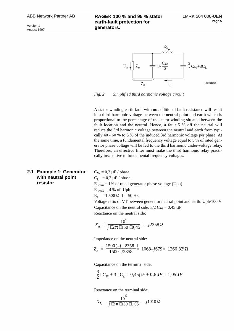
Fig. 2 Simplified third harmonic voltage circuit
A stator winding earth-fault with no additional fault resistance will resultin a third harmonic voltage between the neutral point and earth which isproportional to the percentage of the stator winding situated between thefault location and the neutral. Hence, a fault 5 % off the neutral willreduce the 3rd harmonic voltage between the neutral and earth from typi-cally 40 - 60 % to 5 % of the induced 3rd harmonic voltage per phase. Atthe same time, a fundamental frequency voltage equal to 5 % of rated gen-erator phase voltage will be fed to the third harmonic under-voltage relay.Therefore, an effective filter must make the third harmonic relay practi-cally insensitive to fundamental frequency voltages.
2.1 Example 1: Generator with neutral point resistor
CW = 0,3 µF / phaseCL = 0,2 µF / phaseE3min = 1% of rated generator phase voltage (Uph)E3max = 4 % of Uph Re = 1 500 Ω f = 50 HzVoltage ratio of VT between generator neutral point and earth: Uph/100 VCapacitance on the neutral side: 3/2 CW = 0,45 µFReactance on the neutral side:
Impedance on the neutral side:
Capacitance on the terminal side:
Reactance on the terminal side:
Ze 3x32---
E3
i3Zn
CW+3CLUnCW
2
(X80112-2)
Xn10
6
j 2π 150 0 45,⋅ ⋅ ⋅----------------------------------------- j2358Ω–==
Zn1500 j– 2358⋅( )
1500 j– 2358-------------------------------------- 1068 j– 679 1266 32°Ω===
32--- CW 3 CL⋅ 0 45µF, 0 6,+ µF 1 05µF,==+⋅
XL10
6
j 2π 150 1 05,⋅ ⋅ ⋅----------------------------------------- j– 1010Ω==

ABB Network Partner ABRAGEK 100 % and 95 % stator earth-fault protection for generators. Version 1
August 1997
1MRK 504 006-UENPage 6
Total loop impedance, Zloop:
Fig. 3 Simplified third harmonic circuit, example 1
Hence voltage across the neutral point resistor:
that is, under normal service conditions, 63 % of the induced third har-monic voltage per phase will appear across the neutral point resistor.Hence, when the generator is producing minimum third harmonic voltage,E3= 1% of Uph, the third harmonic voltage U3n will be 0,63 % of Uph.On the relay side of the voltage transformer, the minimum third harmonicvoltage will be:
A typical relay setting would be 75 % of the minimum voltage = 0,47 V.
With the standard setting 5 % of generator phase voltage for the neutralpoint voltage (95 %) relay, the third harmonic undervoltage relay shouldoperate for faults up to say 1,5 x 5 = 7,5 % off the neutral to get overlap-ping of the 100 % and 95 % functions. When the generator is producingmaximum third harmonic voltage, U3 = 4%, an earth-fault 7,5 % off theneutral point will give a third harmonic voltage of:
across the neutral point resistor. On the relay side of the VT, the third har-monic voltage will be:
An earth fault 7,5 % off the neutral also gives a 50 Hz voltage equal to:
on the relay side.
j– 1010 1068( j679) 1068 j1689Ω– 199858°Ω==–+
E3
i3Zn=1266
Un
Ω
-j2358 Ω -j1010 Ω1500 Ω
(X80112-3)
U3n E3=Zn
Zloop---------------⋅ E3
12661998------------ 0 63, E3⋅=⋅=
100V0 63,100---------- 0 63V,=⋅
U3n 4%7 5,100--------- 0 3% of Uph,=⋅=
100V0 3,100--------- 0 30 V,=⋅
100 V7 5,100--------- 7 5 V,=⋅

RAGEK 100 % and 95 % stator earth-fault protection for generators.
ABB Network Partner AB 1MRK 504 006-UENPage 7
Version 1August 1997
From Fig. 5 it is seen, that with third harmonic relay operate value 0,40 V(U2=0,2V), the relay would operate when the combination of 0,30 V thirdharmonic and 7,5 V fundamental frequency voltage is fed to the relay.Hence, with the higher setting of 0,47 V, there is an overlapping from 5 %up to more than 7,5 % off the neutral.
2.2 Example 2: Generator without neutral point resistor
The same capacitance as in Example 1, but the generator has no earthingresistor. The simplified circuit is shown in Figure 4.
Fig. 4 Simplified third harmonic circuit, example 2
Hence third harmonic voltage between the neutral point and earth:
It is obvious that the third harmonic voltage between the neutral point andearth under normal service conditions increases with increasing neutralpoint impedance.
E3
(X80112-4)i3
Un -j2358 Ω -j1010 Ω
U3n E32358
2358 1010+------------------------------ 0 7, E3⋅=⋅=

ABB Network Partner ABRAGEK 100 % and 95 % stator earth-fault protection for generators. Version 1
August 1997
1MRK 504 006-UENPage 8
3 Design
3.1 RAEGK 95 % stator earth-fault protection
The RAEGK 95 % stator earth-fault protection according to enclosed cir-cuit diagram 1MRK 001 054-AB comprises a test device RTXP 18, a DC/DC converter RXTUG 22, a voltage relay RXEDK 2H with filter formeasuring of the fundamental frequency voltage (50 or 60 Hz) and a sig-nal relay RXSF 1. The modules of the 95 % protection are also a part ofthe 100 % protection which is described below.
3.2 RAEGK 100 % stator earth-fault protection with voltage supervision
The RAEGK 100 % stator earth-fault protection acc. to enclosed circuitdiagram 1MRK 054-BB comprises a test device RTXP 18, a DC/DC-con-verter RXTUG 22H, three voltage measuring relays RXEDK 2H, a volt-age limiting unit RXTDA 1, one auxiliary relay RXMB 1 and one signalrelay RXSF 1.
Pos 101: RTXP 18, test switch according to Catalogue 1MRK 512 001-BEN.
When the test-plug handle RTXP 18 is inserted into the test switch, prepa-rations for testing are automatically carried out in the proper sequence, i.e.blocking of tripping circuits, opening of voltage circuits and making ter-minals available for secondary injection testing.
Pos 107: RXTUG 22H, DC/DC-converter acc. to Catalogue 1MRK 513001-BEN.
Input voltage 24 - 250 V, output voltage ±24 V. The converter can beloaded with up to 15 W.
Pos 113: RXEDK 2H, micro-processor based voltage relay acc. to Cata-logue 1MRK 509 004-BEN for the voltage supervision function. Therelay is equipped with filter 50-60 Hz sharp for measuring of the funda-mental frequency voltage (50 or 60 Hz) and is connected to measure volt-age between phases. On delivery, the relay is connected for rated voltageUr = 200 V, which gives scale range 20 - 320 V for stage U1 and 10 -480 V for U2. The relay is set for over-voltage function.
When the time delayed stage U2 of the voltage supervision relay operates,the third harmonic under-voltage relay is released for function. The delayis settable 0,03 - 10 s.
The time delayed voltage stage U1 can be used for generator overvoltagefunction. The definite time delay is settable 0,05 - 16 s.
For remaining technical data, see the catalogue.
Pos 119: RXEDK 2H, micro-processor based voltage relay (set for meas-uring overvoltage) for the fundamental frequency neutral point voltage( 95%) function. The relay is equipped with filter 50-60 Hz sharp formeasuring of the fundamental frequency voltage (50 or 60 Hz). On deliv-

RAGEK 100 % and 95 % stator earth-fault protection for generators.
ABB Network Partner AB 1MRK 504 006-UENPage 9
Version 1August 1997
ery, the relay is connected for rated voltage Ur = 50 V, which gives scalerange 5 - 80 V for stage U1. The definite time delay of the trip output fromstage U1 is settable 0,05 - 16 s.
Pos 125: RXEDK 2H, micro-processor based voltage relay for the thirdharmonic undervoltage function. The relay is supplied with filter 150-180Hz sharp for measuring of the third harmonic voltage (150 or 180 Hz).On delivery, the relay is connected for rated voltage Ur = 2 V, which givesscale range 0,1 -4,8 V for stage U2. Note that the voltage limiting unitRXTDA 1 increases the operate value to twice the value set onRXEDK 2H. The time delay of stage U2 is settable 0,03 - 10 s.
Pos 137: RXSF 1, signal relay with indicating flag according to Catalogue1MRK 508 015-BEN. The unit contains two smaller relays, each withthree make contacts and a red indicating flag. The flag is reset manuallywith an external knob.
Pos 131: RXMB 1, auxiliary relay acc. to Catalogue 1MRK 508 006-BEN. Break contacts with short operate time disconnect the measuringcircuit and open the output circuit of the third harmonic voltage relaywhen the instantaneous stage of the 95% relay operates. A make contactindicates start of the 95 % relay.
Pos 331: RXTDA 1, voltage limiting unit with series capacitor and volt-age regulator diodes.The unit increases the voltage withstand capabilityof the third harmonic relay with Ur = 2 V to 20 V continuously and 120 Vfor 10 s.
3.3 RAEGK 100 % stator earth-fault protection with current supervision
The RAEGK 100 % protection with current supervision function acc. tocircuit diagram 1MRK 001 054-CB includes a micro-processor based cur-rent relay type RXIDK 2H on pos. 113 instead of the voltage supervisionrelay. The current relay is connected to a stator phase current measuringCT. Stage I1 is used for current supervision and I2 can be used for genera-tor overcurrent function. Stage I2 is definite time delayed up to 1s. Fortechnical data, see catalogue 1MRK 509 002-BEN.
The remaining units are the same as those used in RAEGK with voltagesupervision function.
ABB Network Partner ABRAGEK 100 % and 95 % stator earth-fault protection for generators. Version 1
August 1997
1MRK 504 006-UENPage 10
4 SettingSetting of the operating voltages and time delays for relay RXEDK 2H aremade as shown in Connection and Setting Guide 1MRK 509 022-WEN.Observe that the operating voltage for the 3rd harmonic 100% relay isabout twice the setting for U2 due to the voltage drop in the voltage limit-ing unit RXTDA 1.
For RAGEK with current supervision, the operate value of relayRXIDK 2H, is for stage 1: 0,75 - 3,25 A and 0,375 - 16,25 A and for stage2: 0,1 - 40 A and 0,5 - 200 A for protection with rated current 1A and 5Arespectively.
4.1 95 % relay The operating value of the 95 % voltage relay must be set higher thanmaximum neutral point voltage on the generator side in case of an earth-fault on the HV side. When the necessary data are known, the voltage canbe calculated as shown in Appendix A.
Alternatively, the time delay of the 95 % relay is increased to give selec-tivity for earth-faults on the HV side. For block connected generators withneutral point resistor, the setting 5 % of generator phase voltage and timedelay 0,3 - 0,5 s is normally applicable.
4.2 100 % relay The third harmonic voltage will normally vary substantially with the load-ing of the generator. In general, it is recommended to measure the 3rd har-monic voltage to the relay under different loading conditions. Theminimum value will often be obtained when the generator is runningunderexcited with a low active load.
Recommended settings are 70 -75 % of minimum third harmonic voltageand time delay 5 - 10 s.
If the minimum third harmonic voltage of the generator under serviceconditions and the capacitance of the stator circuit are known, the settingof the 3rd harmonic relay can be calculated as shown under chapter 2.
4.3 Voltage supervision relay
The operating value of stage U2 is normally set to 90 % of rated generatorvoltage. The time delay of stage U2 is set to override possible time differ-ence between the activation of stage U2 and the third harmonic relay dur-ing generator running-up. A normal setting is 4 - 5 s.
4.4 Current supervision relay
A normal setting of stage 1 of the RXIDK 2H current supervision relay is20% of rated generator current. The time delay is normally set on 4 - 5 s.
RAGEK 100 % and 95 % stator earth-fault protection for generators.
ABB Network Partner AB 1MRK 504 006-UENPage 11
Version 1August 1997
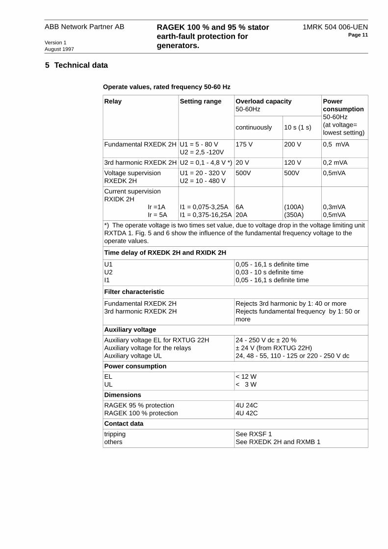
5 Technical data
Operate values, rated frequency 50-60 Hz
Relay Setting range Overload capacity 50-60Hz
Power consumption50-60Hz(at voltage=lowest setting)
continuously 10 s (1 s)
Fundamental RXEDK 2H U1 = 5 - 80 VU2 = 2,5 -120V
175 V 200 V 0,5 mVA
3rd harmonic RXEDK 2H U2 = 0,1 - 4,8 V *) 20 V 120 V 0,2 mVA
Voltage supervision RXEDK 2H
U1 = 20 - 320 VU2 = 10 - 480 V
500V 500V 0,5mVA
Current supervision RXIDK 2H
Ir =1AIr = 5A
I1 = 0,075-3,25AI1 = 0,375-16,25A
6A20A
(100A)(350A)
0,3mVA 0,5mVA
*) The operate voltage is two times set value, due to voltage drop in the voltage limiting unit RXTDA 1. Fig. 5 and 6 show the influence of the fundamental frequency voltage to the operate values.
Time delay of RXEDK 2H and RXIDK 2H
U1U2I1
0,05 - 16,1 s definite time0,03 - 10 s definite time0,05 - 16,1 s definite time
Filter characteristic
Fundamental RXEDK 2H3rd harmonic RXEDK 2H
Rejects 3rd harmonic by 1: 40 or moreRejects fundamental frequency by 1: 50 or more
Auxiliary voltage
Auxiliary voltage EL for RXTUG 22HAuxiliary voltage for the relaysAuxiliary voltage UL
24 - 250 V dc ± 20 %± 24 V (from RXTUG 22H)24, 48 - 55, 110 - 125 or 220 - 250 V dc
Power consumption
ELUL
< 12 W< 3 W
Dimensions
RAGEK 95 % protectionRAGEK 100 % protection
4U 24C4U 42C
Contact data
trippingothers
See RXSF 1See RXEDK 2H and RXMB 1

ABB Network Partner ABRAGEK 100 % and 95 % stator earth-fault protection for generators. Version 1
August 1997
1MRK 504 006-UENPage 12
Operate values, third harmonic relayThe influence of the fundamental frequency voltage varies with the phaseangle between the fundamental and the third harmonic voltages. Fig. 5and Fig. 6 show the worst case, that is, when the fundamental frequencyvoltage has maximum influence on the relay undervoltage operate value.
Fig. 5 Operate values for third harmonic relay when subjected to mixture of third harmonic and fundamental frequency voltages. f = 50 Hz
Fig. 6 Operate values for third harmonic relay when subjected to mixture of third harmonic and fundamental frequency voltages. f = 60 Hz

RAGEK 100 % and 95 % stator earth-fault protection for generators.
ABB Network Partner AB 1MRK 504 006-UENPage 13
Version 1August 1997
Detailed technical data for the components of RAEGK are given in thecatalogues:
6 Receiving, Handling and Storage
6.1 Receiving and Handling
Remove the protection package from the transport case and make a visualinspection for transport damages. Check that all screws are firmly tight-ened and all relay elements are securely fastened.
Check that all units are included in accordance with the apparatus list.
Normal ESD (Electrostatic Discharge) precautions for microprocessorrelays should be observed when handling the packages and separaterelay units.
6.2 Storage If the protection package is to be stored before installation, this must bedone in a dry and dust-free place, preferably in the original transport case.
Component Catalogue
RXEDK 2H 1MRK 509 004-BEN
RXIDK 2H 1MRK 509 002-BEN
RXMB 1 1MRK 508 006-BEN
RXSF 1 1MRK 508 015-BEN
RTXP 18 1MRK 512 001-BEN
RXTUG 22H 1MRK 513 001-BEN

ABB Network Partner ABRAGEK 100 % and 95 % stator earth-fault protection for generators. Version 1
August 1997
1MRK 504 006-UENPage 14
7 Installation, Testing and Commissioning
7.1 Installation The RAGEK relay can be mounted on the support frame in a 19” equip-ment frame or in a RHGX -type relay case.
The height and width of the relays are indicated in the enclosed circuitdiagrams with height (U) and width (C) modules, where U= 44.45 mmand C= 7mm. The depth of the relays, including the connection wires, isapproximately 200 mm. Detailed information about the Combiflex con-nection and installation components are given in the catalogue 1MRK 513003-BEN.
The external connections (which are indicated with dotted lines on the ter-minal and circuit diagrams) are done with leads, equipped with 20ACombiflex sockets, to the RTXP 18 test switch and with 10A sockets tothe relay terminal bases.
Information about the identification system for relays and relay terminalsis given in the catalogue 1MRK 514 005-BEN.
7.2 Testing Insert the RTXP 18 testplug-handle into the test switch, pos 101. WhenRTXP 18 is fully inserted, the banana-plug sockets on the test handle areconnected to the relay circuits, for example, terminals 9 and 10 on the testhandle are connected to terminals 9B-10B for injection of test voltage torelay RXEDK 2H, pos 113 in circuit diagram 1MRK 001 054-AB.
Secondary injection testing with fundamental frequency and third har-monic voltages should be made to verify the set operating voltages andtime delays. Correct output of all alarm and trip functions should be veri-fied.
7.3 Commissioning Secondary testing according to above is a part of the commissioningwork. The function of the protection should be checked when the genera-tor is run up and also when taken out of service. If possible, the third har-monic voltage to the relay should be measured at different generatorloads.
The commissioning work also includes checking of external circuits con-nected to the protection and checking that correct secondary voltages (andcurrent when current supervision is used) are obtained at the relay termi-nals.
8 MaintenanceUnder normal conditions, RAGEK requires no special maintenance. Thecovers of the relay modules should always be installed in place. Mainte-nance testing should be made at regular intervals, say every four years.The testing is suitably carried out with injection apparatus that can gener-ate both fundamental frequency and third harmonic frequency voltages.
RAGEK 100 % and 95 % stator earth-fault protection for generators.
ABB Network Partner AB 1MRK 504 006-UENPage 15
Version 1August 1997
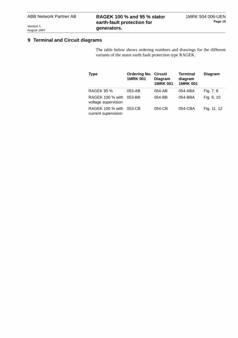
9 Terminal and Circuit diagrams
The table below shows ordering numbers and drawings for the differentvariants of the stator earth fault protection type RAGEK.
Type Ordering No. 1MRK 001
Circuit Diagram 1MRK 001
Terminal diagram 1MRK 001
Diagram
RAGEK 95 % 053-AB 054-AB 054-ABA Fig. 7, 8
RAGEK 100 % with voltage supervision
053-BB 054-BB 054-BBA Fig. 9, 10
RAGEK 100 % with current supervision
053-CB 054-CB 054-CBA Fig. 11, 12
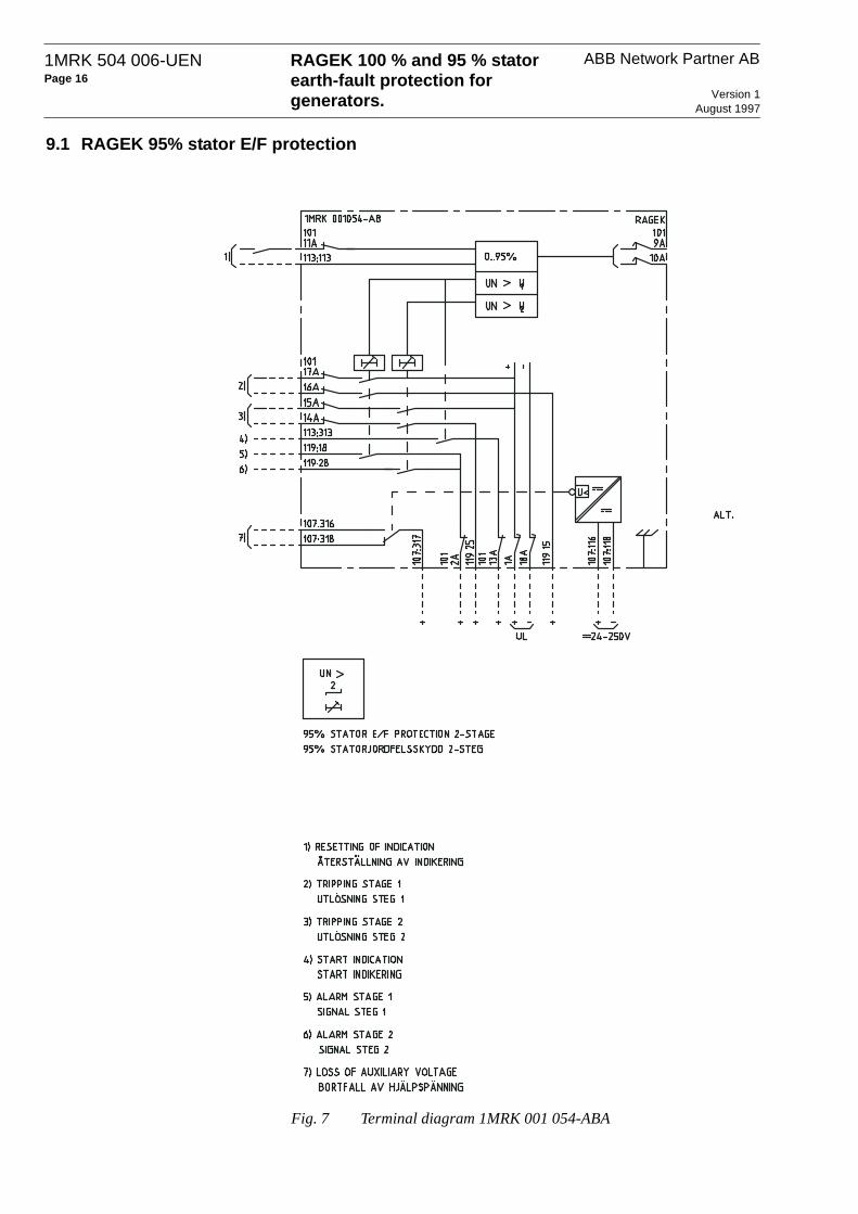
ABB Network Partner ABRAGEK 100 % and 95 % stator earth-fault protection for generators. Version 1
August 1997
1MRK 504 006-UENPage 16
9.1 RAGEK 95% stator E/F protection
Fig. 7 Terminal diagram 1MRK 001 054-ABA

RAGEK 100 % and 95 % stator earth-fault protection for generators.
ABB Network Partner AB 1MRK 504 006-UENPage 17
Version 1August 1997
Fig. 8 Circuit diagram 1MRK 001 054-AB

ABB Network Partner ABRAGEK 100 % and 95 % stator earth-fault protection for generators. Version 1
August 1997
1MRK 504 006-UENPage 18
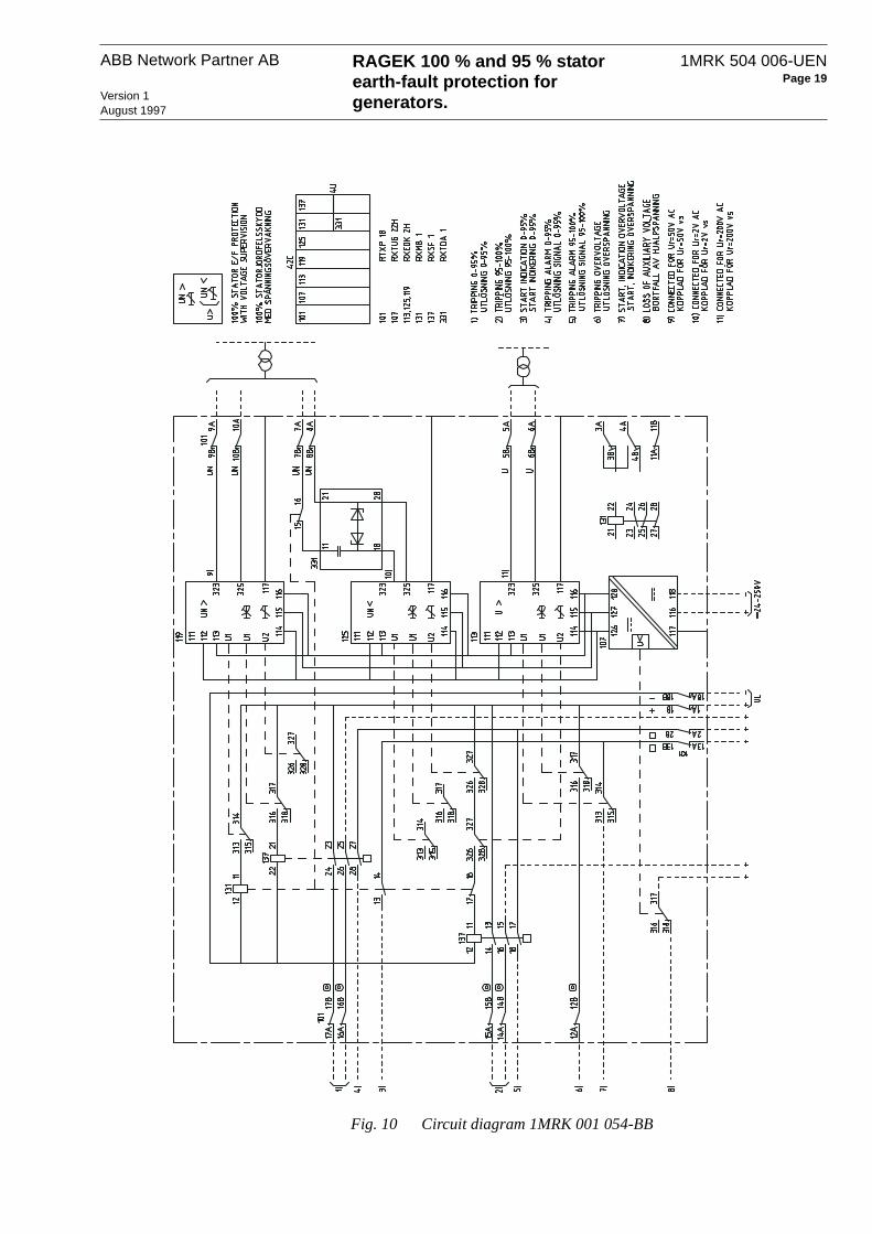
9.2 RAGEK 100% stator E/F protection with voltage supervision
Fig. 9 Terminal diagram 1MRK 001 054-BBA
RAGEK 100 % and 95 % stator earth-fault protection for generators.
ABB Network Partner AB 1MRK 504 006-UENPage 19
Version 1August 1997
Fig. 10 Circuit diagram 1MRK 001 054-BB

ABB Network Partner ABRAGEK 100 % and 95 % stator earth-fault protection for generators. Version 1
August 1997
1MRK 504 006-UENPage 20
9.3 RAGEK 100% stator E/F protection with current supervision
Fig. 11 Terminal diagram 1MRK 001 054-CBA

RAGEK 100 % and 95 % stator earth-fault protection for generators.
ABB Network Partner AB 1MRK 504 006-UENPage 21
Version 1August 1997
Fig. 12 Circuit diagram 1MRK 001 054-CB

ABB Network Partner ABRAGEK 100 % and 95 % stator earth-fault protection for generators. Version 1
August 1997
1MRK 504 006-UENPage 22
Appendix A: Calculation of generator neutral point voltage in case of an earth-fault in the HV network
If sufficient data are available, the neutral point voltage transmitted to thegenerator stator circuits in case of an earth fault in the HV network can becalculated as shown below. If the HV side network is direct earthed andthe generator is provided with a neutral point resistor, the transmitted volt-age is normally reduced to max. 2-3% of rated generator phase voltageand a standard setting of UN=5% is used. For generators connected tounearthed or high impedance earthed networks, the application of an earthfault in the HV net an measurement of the generator neutral point voltagecan be a better alternative than to collect the necessary data for a calcula-tion.
Calculation of the transmitted neutral point voltage:
Fig. 13 Principle circuit for neutral point voltage transmitted
Rg = Generator neutral point resistanceXCT = Impedance of the capacitive coupling between the HV and
the LV winding of the step-up transformer
ohms per phase
XCg = Impedance of the capacitive coupling between the stator cir-cuits and earth
ohms per phase
ω = 2πf (f =50 or 60 Hz)CT = capacitance per phase between the HV and the LV winding
of the step-up transformerCg = capacitance per phase between the stator circuits and earthk = 0,5 for direct earthed step-up transformer HV side, 1 for high
impedance earthed HV systemU0 = zero-sequence voltage on the HV side of the step-up trans-
former.
kU0
1ωCT-----------
1ωCg-----------

RAGEK 100 % and 95 % stator earth-fault protection for generators.
ABB Network Partner AB 1MRK 504 006-UENPage 23
Version 1August 1997
Fig. 14 Circuit data for UN calculation
f = 50 HzCT = 0,009 µF per phaseCg = 0,3 µF per phase
XT kohm
Xg kohm
Impedance referred to 110 kV side:
X” g ohms per phase
X2g ohms per phase
XIT ohms per phase
X0T ohms
Draw the positive, negative and zero sequence networks, simplify and cal-culate the zero sequence voltage U0 as shown in Fig. 16.
0,1 pu20 Ω/phase
60 Ω/phase
1ωCT----------- 10
6
2π 50 0 009,⋅ ⋅---------------------------------- 354= ==
1ωCg----------- 10
6
2π 50 0 3,⋅ ⋅---------------------------- 10 6,= ==
1102
26------------ 0 12,⋅ 56==
1102
26------------ 0 15,⋅ 70==
1102
26------------ 0 1,⋅ 47==
X1T 47==

ABB Network Partner ABRAGEK 100 % and 95 % stator earth-fault protection for generators. Version 1
August 1997
1MRK 504 006-UENPage 24
Fig. 15 Positive, negative and zero sequence network
Fig. 16 Simplified network
kV
kV
j16,7
j17,1
j26,4
E110
3---------=
U0110
3---------
26 4,16 7, 17 1, 26 4,+ +------------------------------------------------ 27 9,=⋅=

RAGEK 100 % and 95 % stator earth-fault protection for generators.
ABB Network Partner AB 1MRK 504 006-UENPage 25
Version 1August 1997
Fig. 17
kΩ
The current I0 is basically determined by the high impedance XCT.
The standard setting UN = 5% will give ample margin.
j10,63,6 27,9
Zg3 6, j10 6,–( )⋅3 6, j10 6,–
---------------------------------- 3 2, j1 1,– 3 38,= = =
I0
k U0⋅XCT
---------------≈ 0 5 27 9,⋅,354
-------------------------= A
U0g0 5 27 9,⋅,
354------------------------- 3 38,⋅≈ 0 134,= kV
0 134 100⋅,10 5,
3------------
---------------------------- 2 2,=≈ % of generator phase voltage

ABB Network Partner ABRAGEK 100 % and 95 % stator earth-fault protection for generators. Version 1
August 1997
1MRK 504 006-UENPage 26
ABB Network Partner ABS-721 71 VästeråsSwedenTel +46 21 321300Fax +46 21 146918