Embed Size (px)
Citation preview
RADIOSCIENCE EXPERIMENTS WITH "MOON-GLOB" ORBITER RECEIVER AND
BEACONS ON MOON'S LANDERS• A.S. Kosov1, O.N. Andreev1, V.M. Aniskovich1, I.A. Babushkin1, S.V.
Fedorov1, L.I. Gurvits3, R.S. Kalandadze1, V.V. Korogod1, S.M. Maleev1, V.G. Nechaev1, S.V. Pogrebenko3, V.S. Rozhkov1, D.P. Skulachev1, I.A Strukov1, Y. Sun5, V.K. Sysoev2, S.G. Turyshev4, V.A. Zotov1.
• 1 Space Research Institute RAS, 84/32 Profsouznaya, 117997, Russia; • 2 Lavochkin Science Production Association, Chimky, Moscow Region, 24,
Leningradskaya St., 141400, Russia; • 3Joint Institute for VLBI in Europe, Dwingeloo, The Netherlands;• 4 JPL, 4800 Oak Grove Drive, 91109-8099 Pasadena California Dwingeloo,
USA; • 5Center for Space Science and Applied Research, Chinese Academy of
Sciences, No.1 Nanertiao Zhongguancun, P.O.BOX:8701 Beijing 100080, China.
• Contact: [email protected]
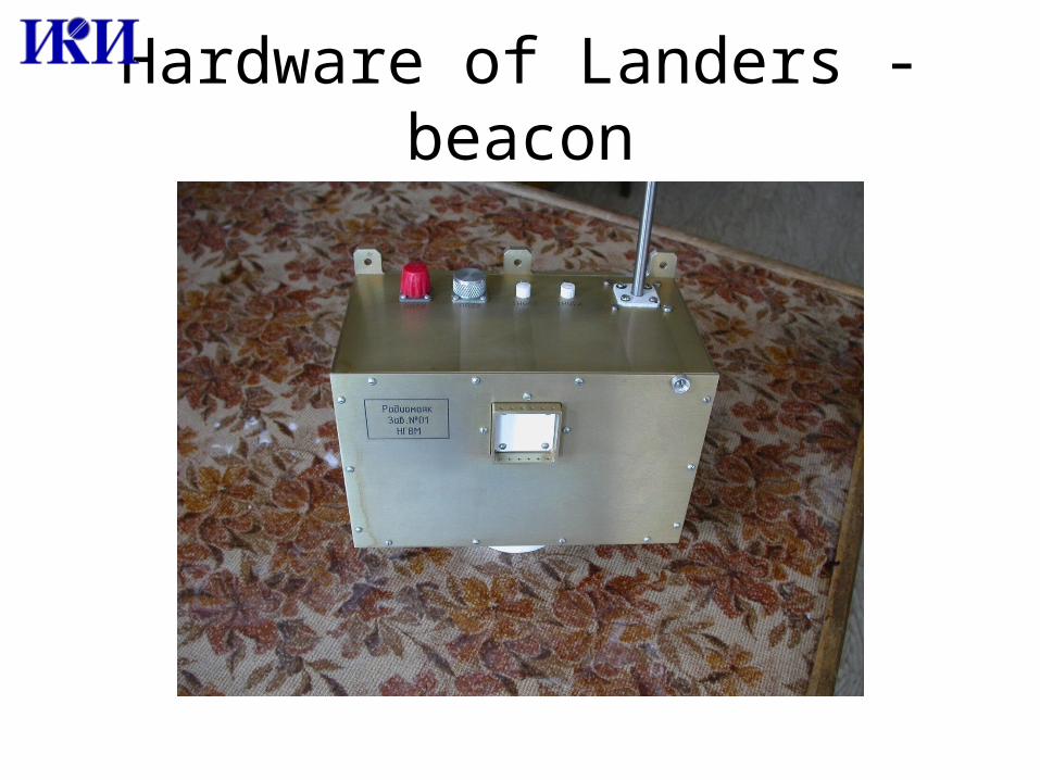
Hardware of Landers - beacon
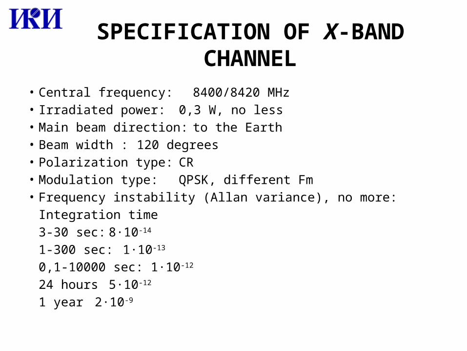
SPECIFICATION OF X-BAND CHANNEL
• Central frequency: 8400/8420 MHz• Irradiated power: 0,3 W, no less• Main beam direction: to the Earth• Beam width : 120 degrees• Polarization type: CR• Modulation type: QPSK, different Fm• Frequency instability (Allan variance), no more:
Integration time 3-30 sec: 8·10-14
1-300 sec: 1·10-13
0,1-10000 sec: 1·10-12
24 hours 5·10-12
1 year 2·10-9
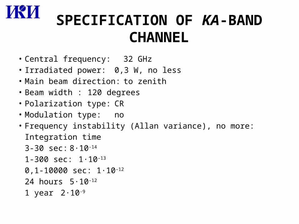
SPECIFICATION OF KA-BAND CHANNEL
• Central frequency: 32 GHz• Irradiated power: 0,3 W, no less• Main beam direction: to zenith • Beam width : 120 degrees• Polarization type: CR• Modulation type: no• Frequency instability (Allan variance), no more:
Integration time 3-30 sec: 8·10-14
1-300 sec: 1·10-13
0,1-10000 sec: 1·10-12
24 hours 5·10-12
1 year 2·10-9
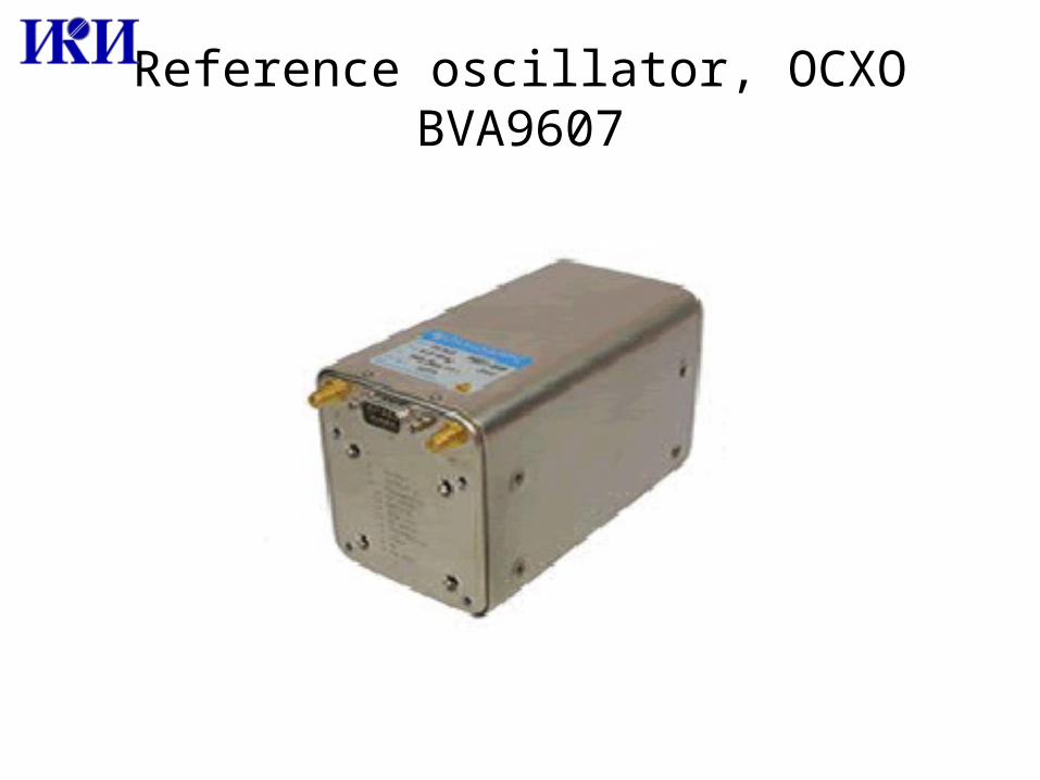
Reference oscillator, OCXO BVA9607
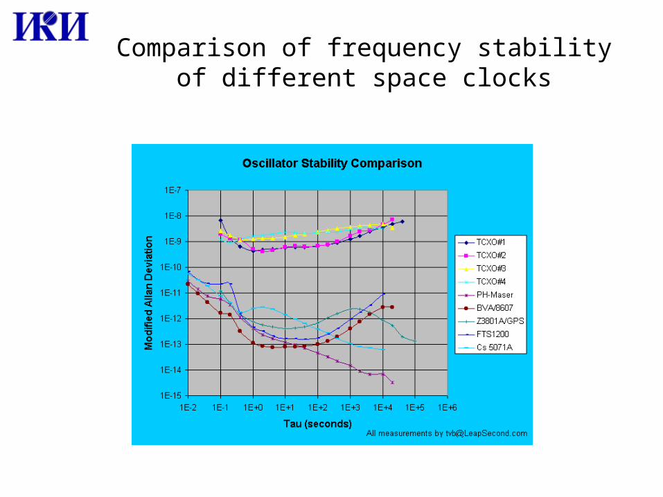
Comparison of frequency stability of different space clocks
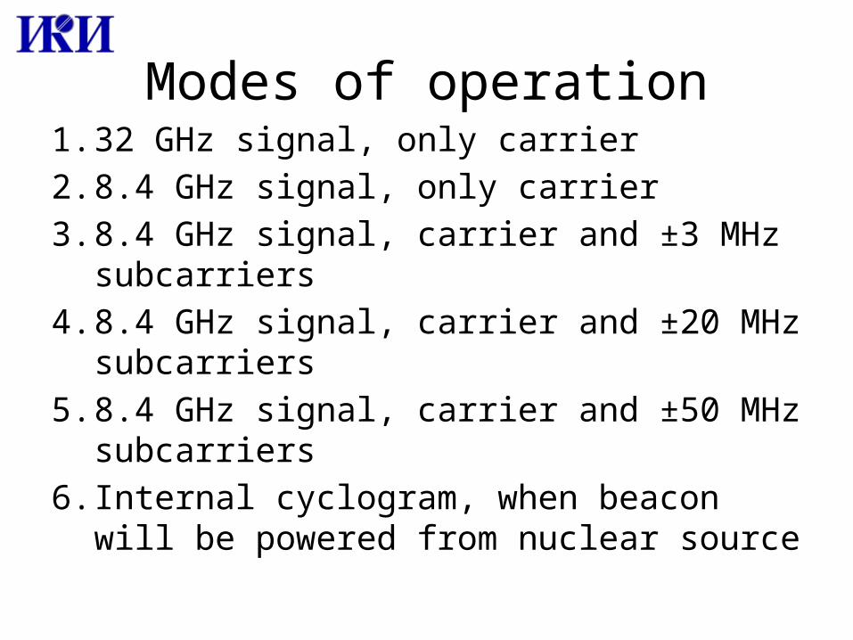
Modes of operation1. 32 GHz signal, only carrier2. 8.4 GHz signal, only carrier3. 8.4 GHz signal, carrier and ±3 MHz subcarriers4. 8.4 GHz signal, carrier and ±20 MHz
subcarriers5. 8.4 GHz signal, carrier and ±50 MHz
subcarriers6. Internal cyclogram, when beacon will be
powered from nuclear source
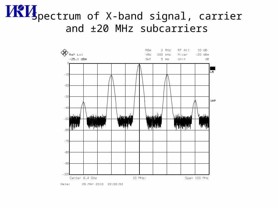
Spectrum of X-band signal, carrier and ±20 MHz subcarriers
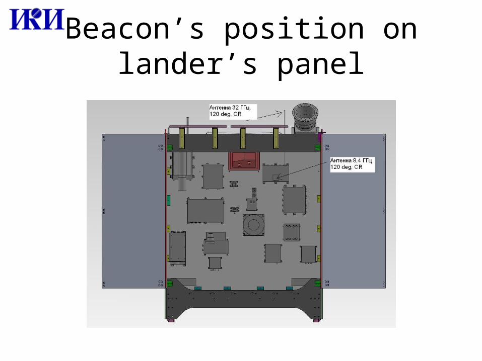
Beacon’s position on lander’s panel
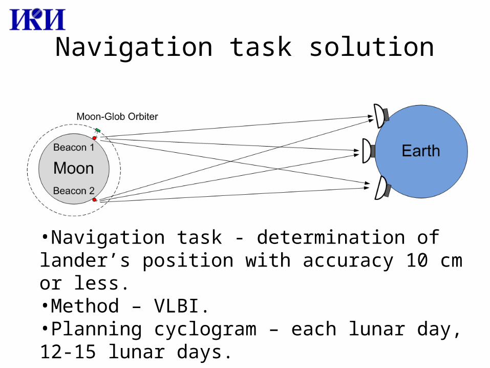
Navigation task solution
•Navigation task - determination of lander’s position with accuracy 10 cm or less. •Method – VLBI.•Planning cyclogram – each lunar day, 12-15 lunar days.
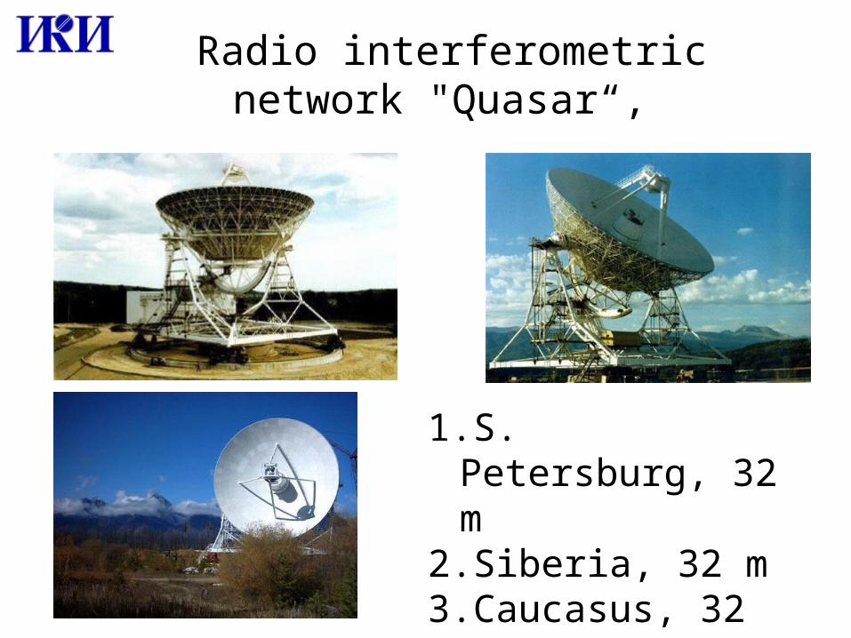
Radio interferometric network "Quasar“,
1.S. Petersburg, 32 m2.Siberia, 32 m3.Caucasus, 32 m
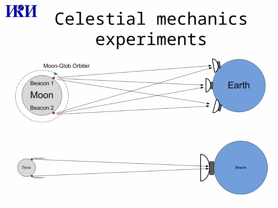
Celestial mechanics experiments
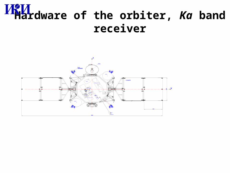
Hardware of the orbiter, Ka band receiver
161
0
8630
1130
Î Í À
Áëî êäâè ãàòåëåé
Ï àí åëè ÑÁ
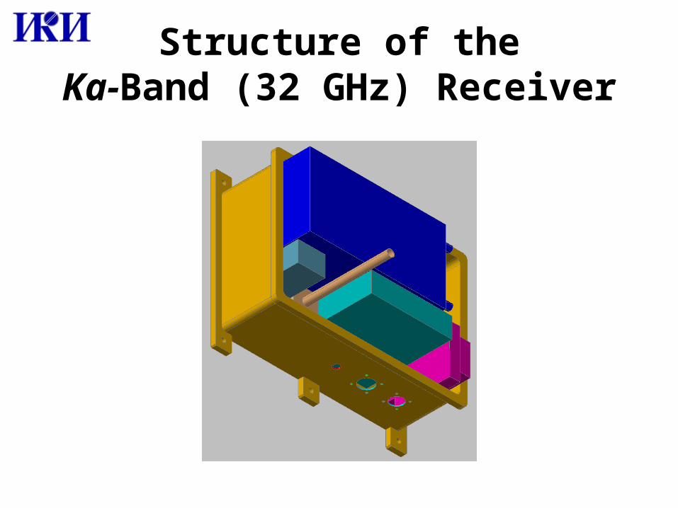
Structure of theKa-Band (32 GHz) Receiver
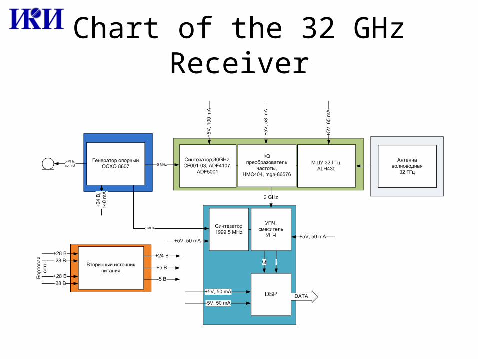
Chart of the 32 GHz Receiver
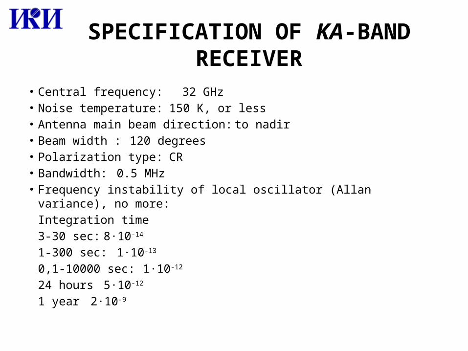
SPECIFICATION OF KA-BAND RECEIVER
• Central frequency: 32 GHz• Noise temperature: 150 K, or less• Antenna main beam direction: to nadir• Beam width : 120 degrees• Polarization type: CR• Bandwidth: 0.5 MHz• Frequency instability of local oscillator (Allan variance), no more:
Integration time 3-30 sec: 8·10-14
1-300 sec: 1·10-13
0,1-10000 sec: 1·10-12
24 hours 5·10-12
1 year 2·10-9
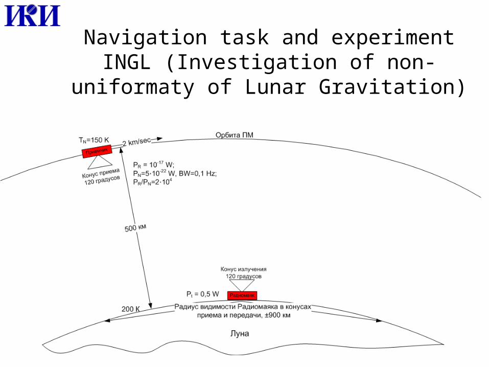
Navigation task and experiment INGL (Investigation of non-uniformaty of
Lunar Gravitation)
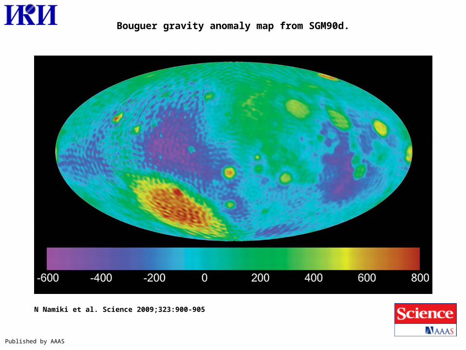
Bouguer gravity anomaly map from SGM90d.
N Namiki et al. Science 2009;323:900-905
Published by AAAS
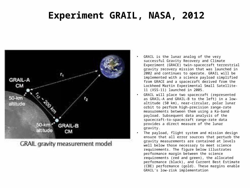
Experiment GRAIL, NASA, 2012
• GRAIL is the lunar analog of the very successful Gravity Recovery and Climate Experiment (GRACE) twin-spacecraft terrestrial gravity recovery mission that was launched in 2002 and continues to operate. GRAIL will be implemented with a science payload simplified from GRACE and a spacecraft derived from the Lockheed Martin Experimental Small Satellite-11 (XSS-11) launched in 2005.
• GRAIL will place two spacecraft (represented as GRAIL-A and GRAIL-B to the left) in a low-altitude (50 km), near-circular, polar lunar orbit to perform high-precision range-rate measurements between them using a Ka-band payload. Subsequent data analysis of the spacecraft-to-spacecraft range-rate data provides a direct measure of the lunar gravity.
• The payload, flight system and mission design ensure that all error sources that perturb the gravity measurements are contained at levels well below those necessary to meet science requirements. The figure below illustrates performance margin between the science requirements (red and green), the allocated performance (black), and Current Best Estimate (CBE) performance (gold). These margins enable GRAIL's low-risk implementation
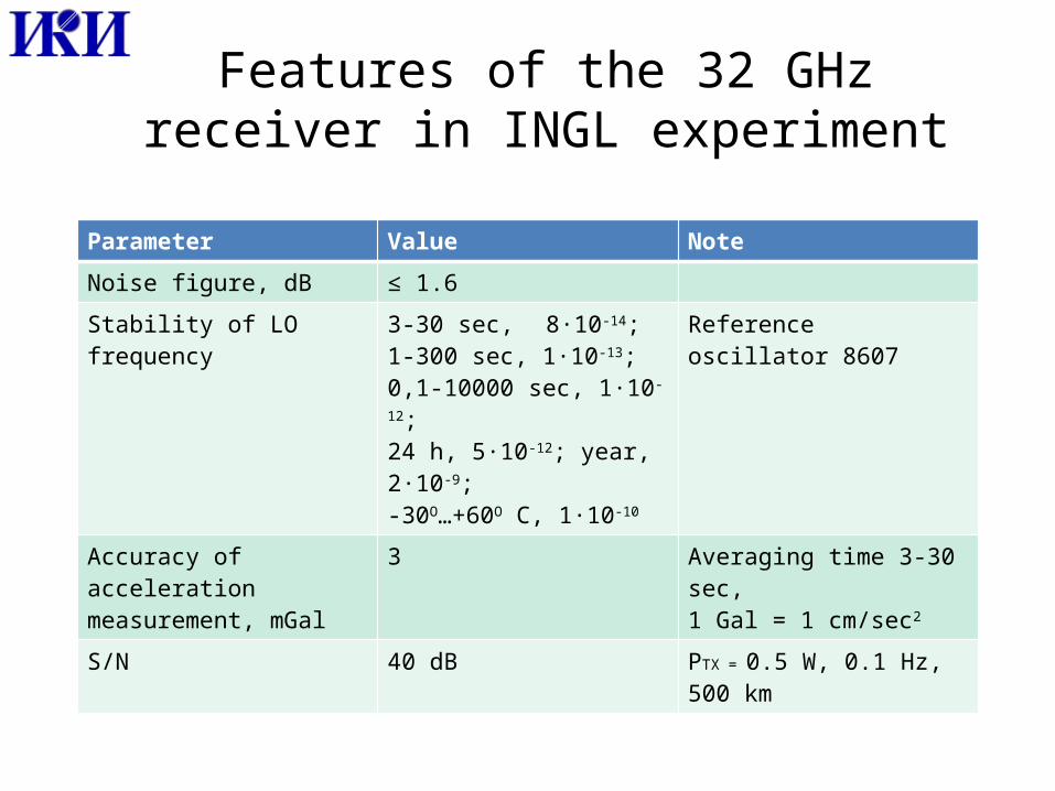
Features of the 32 GHz receiver in INGL experiment
Parameter Value Note
Noise figure, dB ≤ 1.6
Stability of LO frequency 3-30 sec, 8·10-14; 1-300 sec, 1·10-13;0,1-10000 sec, 1·10-12;24 h, 5·10-12; year, 2·10-9; -30О…+60О С, 1·10-10
Reference oscillator 8607
Accuracy of acceleration measurement, mGal
3 Averaging time 3-30 sec,1 Gal = 1 cm/sec2
S/N 40 dB PTX = 0.5 W, 0.1 Hz, 500 km
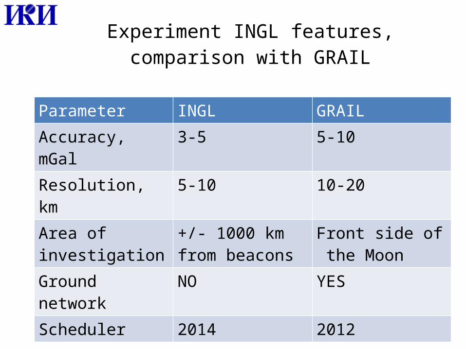
Experiment INGL features, comparison with GRAIL
Parameter INGL GRAILAccuracy, mGal 3-5 5-10Resolution, km 5-10 10-20Area of investigation
+/- 1000 km from beacons
Front side of the Moon
Ground network NO YESScheduler 2014 2012
Mutual operation with another instruments
• Optical instrument and Ka-band receiver on orbiter could measure 3D displacement of the with respect to lander’s position.
• Laser corner reflectors and light emitting beacons on landers will support navigation task.
• It is possible to use precise clock of beacons and receiver to synchronize the navigation complex instruments.
Thanks for attention Questions?