Embed Size (px)
Citation preview

RADIO'S GREATEST MAGAZINE
A 'IG-CRAF
ßAGK, Editor
CANADA 30$ OVER 125 ILLUSTRATIONS
www.americanradiohistory.com

&11rj IA; Siqna/' Ci
For training -for action - the U. S. Army Signal Corps demands sensitive, reliable Radio Phones.
Precision -built Murdock Radio Phones are impor- t ant aids to communica- tion wherever the Arm'
urdoek goes. In peace -in war - since 1904, Murdock has
RADIO furnished `scientific ears' PHONES for the Signal Corps.
MURDOCK MANUFACTURING COMPANY- Chelsea, Mass.
www.americanradiohistory.com

-- I GveYou Both TRAINING AND EXPERIENCE
when I Train You at Home to BE A RADIO TECHNICIAN
lf, BUILD RADIO EQUIPMENT LEARN RADIO THOROUGHLY
from My Easy-to-Under-
stand Lesson Texts
\ Radio Technicians t earn good P
and hold good jobs,
because they now the
Radio - operation of various
know where acircuits- know
wr to trouble when it occurs
and how to perform most efficiently. ently. That st why
tufts to capable Radio Tech -
nic background thorough of every
theory and practice MY 67 Lesson Texts give
theory practical. easy- to -un- der this knowledge in accompanied by hun- dreds
of explanations, diagrams, examples.
hun-
dreds illustrations, ause my Lessons arc You learn quickly at home-with more
than especially for study at
in home more than n7 years of expo
instruction behind them.
With Standard Radio Parts and Tubes 1 Send You
You get, as part of my Course. my 6 Experi- mental Kits of Radio Parts. They contain more than 100 standard Radio parts. including tubes, condens-
ers, resistors, punched chassis bases. hardware, soldering iron. solder, wire, with which you assemble many Radio receiver, Radio transmitter and other Radio circuits, including Fre- quency Modulation circuits. You will assemble a superheterodyne receiver and actually test it with a tester which you assemble. This tester is useful in spare time Radio repair and service work while learning. You get practical experi- ence assembling and testing these cir- cuits -learn how to identify, wire, in- stall standard Radio parts, to test, align Radio circuits you will encounter on actual work as a Radio Technician. This actual work with Radio parts makes the study of my Course fascinating, and gives you valuable practical experience.
And Earn $5 to $10 a Week Ex-
tra in Spare Time While
Learning
o
I show you how to get and handle R dio
service work -how to make $5, $ in
spare time a few months after enrolling. his
gives you practical experience e ithD actual Radios, gives you confidence,
y u u for a good
special "Extra Money Radio
Money JobSheets" show-
ing you how to do more than 60 Spare Time
Radio Jobs. Course
get id Experiments and gain
with m- Ma knowledge paid
skill for their Course with
Maur spare time money earned this way.
GET SAMPLE LESSON FREE
MAIL THE COUPON I want to prove our Course gives practical, money -making information that it is easy to understand -what you need to master Ra- dio. My Sample Lesson Text, "Radio Re- ceiver Troubles -Their Cause and Remedy," covers a long list of Radio receiver troubles in A.C., D.C., battery, universal, auto, T.R.F., superheterodyne, all -wave and other types of sets. And a cross reference system gives you the probable cause and a quick way to locate and remedy these set troubles. A special sec- tion is devoted to receiver check -up, align- ment, balancing, neutralizing, testing.
PROVE YOUR KNOWLEDGE By Tests and Experiments on Equipment You Build
My Special Lesson Texts supplied with my 6 Experi- mental Kits of Radio Parts
show you how to test the per- formance of the circuits you build and how to use the test ecluipment in measuring voltage, current, resistance, amplification -how to test and align the circuits for most efficient operation -how to detect trou- bles in circuits and how to correct them. You learn these facts quickly by actually working with real Radio equipment in- stead of simply reading books. You get both the knowledge and experience you need to make extra money in spare time while learning -and to fix commercial Radio equipment when you become a Radio technician. Mail the Coupon NOW.
Why More Radio Technicians Now Make
$30, $40, $50 a Week Than Ever Before It takes both Training and Experience to qualify
A
a a killed Radio Technician. You get BOTH with my Course. That Is why Radin Technielans I
trained are cashing in on the booming Radio repair business existing now due to the shortage of new
lame and auto Radio sets. Keeping the country's 7.100,000 Radios playing, repaired and furnishing
new tubes and parts gives good Jobs to thousands of
part time and full time Radio Technicians; enables many to open their wen Radio businesses. N. It. I. Trained Teehniclaus and Operators hold good jobs in many of the country's 882 Broadcasting Stations. and in Aviation. Pollee. Commercial. Marine and Ibn Brament Radio. Loud -Speaker Systems give goal ions to many. Others are getting good Civilian Radio jabs with the Government ; winning extra rank and pay In the Army. Navy: holding gaol jobs in fac- tories which are busy making n11111° is of dollars worth of Government Radio Equipment. Because my
graduates are thoroughly trained. they will cash in on Radio developments such as Televlsbm and
"g.M." after the war.
RADIO-CRAFT for MAY, 1942
77 EXTRA
',fit PAY INS ARMY, NAVY, T00
Men likely to go Into military sere- tre. soldiers. sailors. narines, should mail tito Coupon Now' Learning Radio helps men get ex- tra rank, extra prestige, more in- teresting d u t y at several times a prl- rato's baso pay. Also prepares for good It a d I o jobs after service ends. ITS SMART TO TRAIN FOR RADIO NOWT
Beginners Extra Fixing Radios In Spare Tiesea
Nearly every neighborhood offer, opportunities for to
money 1 fixing liRa Radio sets. Because of the make extra
demand for Radio repairs. these opportunit lea aro
Increasing rapidly. I trails you to take advantage of these
n h st lea-to extra vl ling
a few mo after you enroll- -to gain valuable ex-
perience In practical Radio work.
MAIL THE COI-PON -get my Sample Lesson and
64 -page Rook "Rich Rewards in Radio- NOW.
trained Techo See
cianora Radio Learn
you ow how
WY Course really is. Read letters from more
than 100 men I have trained so you can see what NOW-
in are
nvelope or earning.
pasted i alt la penny po NO stal\V-
1. E. SMITH. President. Dept. 2EX
NATIONAL RADIO INSTITUTE, Washington, D. C.
600D TOR Rom S6A4 ON FREE J. E. SMITH. President. National Radio Institute Dept. 2EX. Washington, D. C. Without ohlirating me. mall your Sample Leeson
e,Ì in then branch kif Radio checked heckedrb below. (NnU let -
w,ll call. Write plainly.) osa sales-
man Radio Service Cuti Aviation Radio
Sersvice My
Technician ing rStations roideat4
for Radio stores and Army. Navy. Radio Factories O Operating Police Ra-
o Spare Time Radio dio Stations Servicing D Operating Ship and
D Auto Radio Technician Harbor Radio irf you nave not decided which branch von prefer
-mail coupon for facts to help you decide.)
Name
Address
City State
r r, ,,;,
` R REWARaS
'V RADIO ,y t/' .
f
513
www.americanradiohistory.com

Incorporating
H. W. SECOR Managing Editor
HUGO GERNSBACK Editor -in -Chief
G. ALIQUO Circulation Manager
Contents MAY, 1942 Issue
VOLUME XIII -- NUMBER 9
Mailbag 516
Editorial: A Communications Paradox Hugo Gernsback 519
The Radio Month in Review 520
RADIO DEFENSE Hand Radiophone (Front Cover Feature) H W. Secor 522
The Radioman Keeps 'em Flying E. H. Leftwich 523
SERVICING "War-Time" Servicing Willard Moody A Line Voltage- Booster Lionel Haid What Condenser Ratings Mean J W. Straede, B.Sc
Servicing Personal Radios in Institutions Floyd D. Goff RADIO SERVICE DATA SHEET:
No. 322. Pilot Model 340 Series
SOUND A Complete P.A. System .. Ricardo Muniz, E.E.,
and Robert J. Bergemann, Jr.
Using Theater Sound Systems for "Hearing Aids ".. G. R. LaPoint
Paper -Disc Sound Recorder
Build YOUR OWN Experimental Electronic Organ.. W. K. Allan
A Modern High -School Sound System ... ...Mahlen Moore
IN THE ISSUE from
Signal Odd Indic °"
"Magic EN e" Indic
for Measure-
ments Rectifier
Nrcr °ft Detector Am-
plifier
voltQge
DEPARTMENTS, ETC. Mailbag .. 516
The Radio Moth in Review 520
Operating Notes 537
Book Reviews 553
RADIO SERVICE DATA SHEETS (See Servicing) 532
Latest Radio Apparatus .. 560
RADIO & TELEVISION 524 A.C. Variable Pitch Code Oscillator J. S. Lee, W8C2P 563
526 A 2 -Band Midget -Tube Receiver .... L. M. Dezettel, W9SFW 564
528 Talking on a Light Beam James Solms 566
530 Experimental "Chew -Box" Mike 568
Radio Hook -ups 569
532 Question Box 570 Radio Patents Review 571, 572
Amateur Radio 575
534
537
538
540
544
ENGINEERING What Happens in Resonant Circuits? Willard Moody 546
EXPERIMENTERS Constructing a Simple Photo -Electric Cell Louis Castelli 548
Home -Made Arc Lamp Joe Nonwicz 550
Automatic Voltage Regulator S Gordon Taylor 551
TEST INSTRUMENTS A Portable U.H.F. Oscillator George F. Baptiste 554
D.C. Vacuum Tube Voltmeter Harry S. Bixby 556
FM
Published by Radcraft Publications, Inc. Publication office: 29 Worthington Street, Springfield, Mass. Editorial and Advertising Offices: 25 West Broadway, New York City. Chicago Advertising Office: RADIO -CRAFT, 520 North Michigan Avenue, Chicago, Ill.
RADIO -CRAFT is published monthly, on the first of the month preceding that of date; subscription price is $2.50 per year in U. S. (In foreign countries, 75c additional per year to cover postage; Canada, 50c additional.) Entered at the post office at Springfield as second -class matter under the act of March 3, 1879. All communications about subscriptions should be addressed to: 29 Worthington Street, Springfield, Mass., or Director of Circulation, 25
West Brcedva., New York, N. Y.
* Foreign Agents:
London -Gorringe's American News Agency, 9A Green St., Leicester Square, W. C. 2, England.
Paris -Messageries Dawson, 4 Rue Faubourg, Poissonniere, France.
Melbourne -McGill's Agency, 179 Elizabeth St., Australia.
Dunedin -lames Johnston, Ltd., New Zealand.
* Text and illustrations of this magazine are copyright and must not be
reproduced without permission of the copyright owners.
* Simplified "FM" Receiver Alignment.. L. M. Dezettel, W9SFW 557 Copyright 1942 Radcraft Publications, Inc.
514
www.americanradiohistory.com

"THERE IS A BRIGHT SIDE " --] An Open Letter to Users of Electrical Measuring Instruments
Much more than instruments is needed to fill the vast require- ments of America's gigantic production program. Experience gained by many years of actual instrument manufacturing is vital. Triplett's broad experience in filling peace -time needs is answering the call to arms -is doing its part in re- establishing in the world
the Democratic ideals of freedom.
Private business must undergo restrictions for the sake of
National security. As good Americans we will bear these willingly.
And there is a bright side. Rapid expansion, new fields and improved processes mark today's instrument program. New de-
velopments unbelievably revolutionary in their scope are growing out of the vast proving ground of war -time production. When war ends, these advantages will be passed on to all of you. From the experience of today will come many new and greatly improved instruments to better serve the peaceful world of tomorrow.
° DEFENSE
BUY UNITED STATES SAVINGS RONDS ND STAMPS
Sales Manager
THE TRIPLETT ELECTRICAL INSTRUMENT CO.
We Can All Help .. . Buy Defense Stamps and Bonds. Buying them
regularly is the best way you can help General MacArthur and our fighting men. We must all pull together now, and your dollars can best serve in stamps and bonds.
THE TROPLETT ELECTROCAL INSTRUMENT CO. BLUFFTON, OHIO
RADIO -CRAFT for MAY, 1942 515
www.americanradiohistory.com
MAILBAG
mSAN /N SERVICEMA
5tRVIGE
by FRANK FAX
ASHORT time ago Uncle Sam told the radio-buying public, "That's
all there is, there isn't anymore." That puts it up to you servicemen to keep the nation's radio sets -57 million of them -in trim for the duration. Yes sir, there's plenty of work ahead, but to get your share, you've still got to scratch for it. And that's why we've prepared a couple of new sales helps to add to the long list now available to you. One is a set of "Radio Alen" post- cards. These emphasize the importance of good radio reception in air raids and black -outs, pointing out that radio may be the only open means of com- munication during alerts. The price of the cards to you is just a penny apiece for postage. The other new item is a booklet of radio caretaking hints for housewives -a timely reminder to the ladies that their annual spring scouring should include a look -in at the radio, too. Every one of the thirty helps listed below - including the two new ones - is obtainable at your local jobber. Or, if you prefer, write direct to me, Frank Fax, Dept. C- 5,Hygrade Sylvania Corporation, Emporium, Pa.
I. Window displays, dummy tube cartons, timely window stream. ers, etc. (From your Sylvania jobber only) 2. Counter displays 3. Electric clock signs 4. Electric window signs 5. Outdoor metal signs 6. Window cards 7. Personalized postal cards 8. Imprinted match books 9. imprinted tube stickers 10. Staines, cards 11. Doorknob hangers 12. Newspaper mots
13. Store stationery 14. Billheads 15. Service hints booklets
16. Technical manual 17. Tube base charts 18. Price cords 19. Sylvania News 20. Characteristics sheets 21.Interchangeable tobe charts ' 22. Tube complement books 23. Floor model cabinet 24. Large and small serv- ice carrying kits 25. Customer card Index Rles 26. Service garments 27.3 -in -1 business forms 28. Job record cards (with customer receipt) 29. "Radio Alert" Post. cards 30. Radio Caretaking Hints to the Housewife
SYLVANIA RADIO TUBE DIVISION
HYGRADE SYLVANIA CORPORATION
316
REPAIRING CONDENSERS Dear Editor:
I have a low -loss ceramic- insulated mid- get condenser which fell off my work bench and the insulating material was broken. Being the only one of its kind that I had I needed it very badly. I took a piece of good masonite and cut it just a little larger than the condenser when open and drilled the shaft hole in the muddle. A smaller hole was drilled at the bottom also and then I bushed it up until the rotor plates moved freely.
This little condenser can now be mounted by drilling small holes at the top and the bottom of the masonite strip.
HOMER L. DAVIDSON, Fort Dodge, !a.
RE: RADIO BEAMS Dear Editor:
In reference to your article on "Radio in Aviation" and Radio beams in your Jan.-Feb. Radio- Craft. This was very in- teresting and I, for one, would like to see lots more such articles. This article should prove of interest to flyers as well as Radio- men. Keep up the good work!
LESTER L. WILLIAMS, Las l'egas, New Mexico.
HEAD -PHONE RECEPTION FOR HOSPITALS
Dear Editor: Since Mr. Shaney answered my letter to
him about how to get good phone reception, in your July, 1941, issue, I have been work- ing with output transformers, different pairs of phones, condensers, tone controls, etc., and I am beginning to get pretty good phone reception. So I am becoming inter- ested in the thing which, next to good phone reception will, I believe, help me more than anything else to get the doctors and super- visors here to make a rule requiring the use of phones with all private radios; in fact many hospitals require the use of phones with all private radios.
I wrote Mr. C. Seymour who mentioned in his letter published in your July, 1941, issue, that he maintained radios in a hos- pital where loudspeakers were not permit- ted, but I want to come in contact with more servicemen who also maintain radios in hospitals where phones are required with all the private radios used by patients.
Will you please publish this letter, ex- cerpts from it or a small notice asking any serviceman who knows of hospitals or sanitariums which require the use of phones with all private radios to write me about them, giving their names and ad- dresses?
JEROM E FOWLER, Tuscaloosa, Ala.
WAR -TIME USES FOR FM Dear Editor:
In the January- February issue of Radio - Craft Mr. Hugo Gernsback, in his editorial "U. S. Radio At War" mentions the neces- sity for reliable, short range communica- tion between planes and subs. Also "Only new radio ideas of course can be used."
I believe that there are possibilities in "FM" which may have been overlooked in this particular case. In saying this I am not criticising. Humans can be compared to the monkey who had his hand caught in the jar of nuts. They often overlook a solution that is close by, while racking their brains for an idea which will fill the bill.
FM has already joined the U. S. Army for use in tanks and scouting units, where interference makes the use of AM difficult or impossible. (No. I didn't learn this from the Fifth Columnists.) Just to refresh your
memory, some of the advantages of FM which make it a good solution to the "plane -sub" problem are:
(1) Short -range transmission (2) Easy adjustment of range (3) Compactness of -units (4) Low -power operation (5) Low -cost operation (6) Reduced interference (7) Complete absence of distortion due
to station interference, and ability to "blank -out" an enemy unit by slight- ly increasing power.
(8) Simplicity of equipment as com- pared to the ultra- shortwave trans- mission as suggested by Mr. Gerns- back.
Frequency Modulation lends itself almost perfectly to such wartime needs, and the United States has the jump on the Axis in being able to put it to work immediately!
We are shoulder to shoulder in the fight for freedom. Let's all swing together to put the axe to the Axis and the boots to the Japs!
H. L. HEwirr, Grenfell, Sask., Can.
SUCCESSFUL WITHOUT THEORY
Dear Editor: I have noted what some readers have
been writing, 'that all Servicemen are "gyps," and should be forced to get a Gov- ernment license. That is what I call the "bunk." I believe that 80 or 90 per cent of the radio mechanics who really fix radios do not know theory. I have worked on the same bench with a man who knew radio theory and yet could not repair a radio as rapidly as I. Practical experience is what counts -and that certainly is the best school. I acquired my knowledge of radio from practical experience and yet am making a good living without theory.
As to what we would call a "quack," I believe he should keep on ; he makes busi- ness good for a good mechanic. This is due to the fact that when people get to know him, they will not go back to him, but will go to a reliable mechanic.
So, men, why not let's all pitch together and not try to "knock" the so- called me- chanic. There is enough work and business for us all. Let us hear from some more of your RSMA members. I would like to have one of those buttons myself.
CONRAD ADIIRIGHT, JR., Texarkana, Arkansas.
NEW BUSINESS! SERVICING "DIATHERMY" MACHINES
Dear Editor: We operate a Radio-Electric shop here
in this city of 5,000 population. I am the radio Serviceman and have a first -class line- up of equipment and a very good record for service. I am not saying this to "brag," but only to state my position.
I recently had the opportunity to service a diathermy machine for one of the local doctors. I sent the tubes in to Chicago for test and found that one was bad, so the remedy was easy. However, after talking to several of the doctors and the superin- tendent of the local hospital, I have come to the conclusion that I have been passing up some good business in this line. There are many of these diathermy machines and X -Ray apparatus both here and in the sur- rounding smaller towns. Whenever they need service, they have to ship them in to Chicago. Naturally this takes quite a bit of time, so they are all willing and anxious to have them repaired locally.
Will someone advise me how to break into this business, where to get the neces-
RADIO -CRAFT for MAY, 1942
www.americanradiohistory.com
sary technical service bulletins, diagrams and instructions? Can you also tell me what type of testing equipment is necessary, etc.? Can you give me something on the price schedules for labor on this type of equip- ment? I presume this type of work would command a much better price than ordinary radio work.
I believe there are lots of us who are passing up service work like this, either because we have never thought of it or have hesitated to go into it. After all it is
in our line and should be "right down our alley." It should be worked up into a
profitable source of income. I am a regular reader of Radio -Craft but
do not remember seeing any article on this type of service. e
Any help you can give will be greatly appreciated.
By the way -after replacing the tube in the aforementioned diathermy it worked perfectly. The doctor wrote to the company and told them I had "repaired" it very effi- ciently, and asked for service notes and a
diagram. They answered by saying that they did not divulge any information con- cerning their machines and did not publish diagrams. But, would he contact his serv- iceman, ask him to write to them and tell them what the trouble was and how he corrected it, so that they in the factory might try to remedy that in future ma- chines before they left the factory! Now, isn't that nice! They will not even offer to help, but expect the poor Serviceman to give them all the hard -earned information he has gained!
R. H. JURGENS, Madison, S. Dak.
HELP THE "HOME EXPERIMENTER"
Dear Editor: I think the beginner in radio is due a
good deal of attention and encouragement from others who have preceded him in this field. A good many of these beginners are handicapped by lack of money in their endeavors to get ahead and, as a result, some become discouraged and turn towards something else that, although less money is involved may not be as profitable in the end.
Many of these beginners become whole- heartedly interested ¡jl radio, and, as a result, do a good deal of experimenting, if they can obtain the equipment with which to work. Quite often one reads of some person interested in certain type of work, experimenting with simple equipment in his 'home workshop," and suddenly making a discovery that astounded learned scien- tists, with their great modern laboratories filled with the best and most expensive equipment. If that person had given us his experimenting and turned in another direc- tion, because of difficulties in obtaining his simple equipment, and because no one en- couraged him in his endeavors, the world would have gone on for scores of years, perhaps, ignorant of what might be the greatest discovery of all time.
I don't mean to say that all "home work- shops" would turn out famous inventors, but I do say that there would very likely be a greater percentage, if these beginners were given encouragement from such sources as the local servicemen, the ama- teurs and the schools. The schools could provide simple, inexpensive equipment and, although not including it in the curriculum, they could encourage students to carry out experiments and do simple set -building, in order to master the first principles of radio. In this manner the beginner would have access to equipment that would, perhaps, be too expensive for him to own.
RADIO-CRAFT for MAY,
Many servicemen, amateurs and other people have old discarded sets using the old type tubes, such as the 27's, 35's, etc. I f they would turn these over to the experi- menting beginner in radio, they would do much to encourage him at this stage of his education. -
These old tubes and other parts are not as nice to work with, I grant you, as the newer ones; but they will work -and in using them he can carry out quite a num- ber of excellent experiments. For one thing the parts cost him next to nothing, for most people are glad to get rid df them; also, if he burns out a tube or breaks a
part, he does not suffer much expense in replacing it.
As time goes on he can save more money and purchase better equipment with which to work. Eventually he will want to take a course in radio engineering and become a
full -fledged radio technician. However, without that little bit of attention and en- couragement from others, he would, per- haps, still be an insignificant figure among the millions, working away at a low -paying job he may not like. It is needless to repeat that in these days of war there can't be too many well -trained radio technicians.
So, how about it, you people that are able to help these would -be radio hams? Are you going to hand out that old dis- carded radio and electric equipment from your attics or cellars, and hand it over with your best wishes? You have nothing to lose and everything to gain, so get busy right away, won't you?
GERALD CHASE, Burford, Ont., Can.
THE RADIO REPAIR MAN Dear Editor:
Every day throughout the country, hun- dreds of radios are repaired. Back of all this repairing you will find the "repair man." Although few people realize it, this man controls, to a certain extent, whether or not the public hears the news, their favorite music or actor, and public leaders. Prob- ably the servicemen did not 'think of this angle of their work themselves.
Actually the radio repair man is per- forming a public service. He represents one
of the pillars of democracy. His never- ceasing work may be compared to a doc- tor's practice. No matter what hour the need arises, the radio repair man is ready to go anywhere to repair anyone's radio. Of course as with doctors, so with repair men, you will find men who are not up- holding the honor of the radio trade, but merely working for themselves. This kind of man you will find in every profession, but fortunately, they are few and far be- tween.
Too many people take the repair man as a "standardized" member of the com- munity, little realizing what they would do without him. He is one man in your town you can depend on to be ready at all times for whatever might come along. In the summer you will find him stocked up with batteries for your portable radio. Yes, and most likely he will be ready to rent you a portable radio for your fishing trip, or a small mantel set for summer cottage use. Then again he will have plenty of flashlight batteries, because the summer time is the time when more flashlights are used.
But no matter what time of year you take your radio to him, you will find him ready to give you the prompt and courteous service he advertises. Yes, you can truth - fully say that the radio repair man is a
credit to and a builder of our country. D. MCBRIDE, Newmarket, Ontario, Can.
1942
MAILBAG
TECHNICAL BULLETINS
Technical bulletins give reliable information in ea y -to- fellow form, and save valuable time otherwise spent in laborious reading of numerous books. Every subject is treated briefly and con -
cisely. yet completely. No complicated math- ematics, chemistry, electricity, or theory. Each
bulletin la written in simple language.
PRICE $1.00 EACH POSTPAID ORDER BY NUMBER
D10I -USING NICHROME RESISTANCE WIRE. -How to repair electric Rat irons. toasters, rheostats. resistors
and six Ire r htic heating devices Figuring
le
0113 -NOW TO DESIGN SOLENOIDS AND PLUN- GER MAGNETS.-Anyone
cannot aR dlat interested
without this solenoids
simple and practical information.
0.129- COLORING METALS CHEMICALLY.-Form- ulas for producing colored finishes on brass. copper. true. aluminum and alloys by simple chemical prooesees.
0- 132 -WORKING WITH PLASTICS. - Information about new material that combines advantages or wood and metal.
D -141 -R E C O R D I N G THERMOMETER EASILY MADE.- lnforotation on building device to record tem- perature over 12 arrL stat a clock anti a sensitive element carrying pen that mrks temperature fluctuations on s paper chart.
O .104- SILVER SOLDERING AND BRAZING.- Practical ptethmis of brazing, silver soldering. and hard soldering. Tables giving the composition of brazing' and soldering alloys, and fluxes.
D 119- ELECTROPLATING WITH ALLOYS. -New practical pureases for bronze brass and cadmium direr silos. -
D- 121 -CORROSION, CAUSES AND PREVENTION. -Information about corrosion and methods of controlling its destruetIse eieds ma plumbing and heating system., tools and machinery, automobiles.
0139 -RUBBER MOLDS FOR CASTINGS.-rnetruc- tlone for making the original model. preparing the rubber mold, and casting useful articles front liquid Plastic, magnesite and other materials.
D -105- ELECTROPLATING WITH GOLD AND SIL- VER.- Formulae and Instructions for electroplating with gold and silver by efficient proms.. Formulas for green gold, red gold and other finishes.
0122- STAINLESS STEEL EASILY SOLDERED. BRAZED OR WELDED. -Complete practical methods of soldering. brazing and welding stainless steel. including formulas for solders and fluxes.
1)-128 -HOW TO DESIGN AND BUILD HY- DRAULIC RAMS.-t'omplete directions for surveying springs and stream,. flow to build and Install hydraulic rams.
0.146-SIMPLIFIED CASTING METHODS. -SImpIa and rapid methods of making castings in soft metals without sand molds. for models, ornaments, toe. and many useful articles.
Each Bulletin consists of a set of large sheets.
assembled in one packet. size 9 z 14./e: weight v. lb. Numerous illustrations. diagrams. charts to
Supplement text.
Ì f .CHNIM 1917 S. STATE ST. (DEPT. 542) CHICAGO, ILL.
r
i
DEPT. 542
TECHNIFAX 1917 so. state. Chicago. ul.
Enclosed find S for which please send me postpaid the following Technical Bulletins:
Nos.
Name
Street and Number
City and Stata d
.5I7
www.americanradiohistory.com
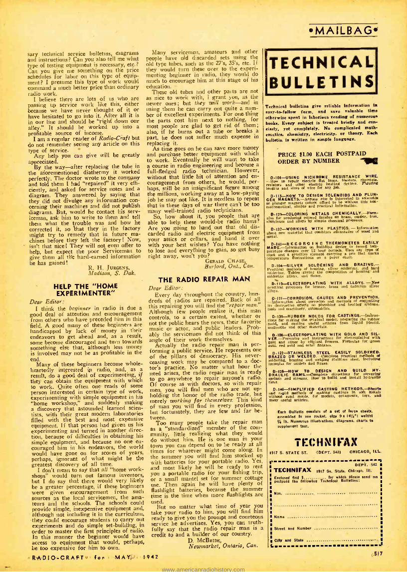
EXTRA QUALITY COUNTS MORE THAN EVER
THESE DAYS...
W'-" EO lflEtA\`\ZEO -be on \Y t ''eoe wilti It ¢
among Mela \\ ae - ype e \amen\ ls, s'ç.' V a \o: l e
ana a\
\tgb -power ana \stq\s- co\la9s \Yp P veal . Comp \ele\y saa\ee, ana inen\a ea Von.
a a 2 w \a\\ e tee. Mo \e \uie -Ptoo\ ana v "bc a\on- Atoo \. /2.
POWER W\RE WOVNOS-TtieY ataétpale \tea\ \aslac
-a\end ovet\Daos b¢t\ec-a<e plolec\ea a9á,nal òy
an ex \uéwe C\lmalaRcao\¢a emen\ Coal.c.q. S3 alanaaca
...as ana a\.apee, :Also ab\¢nYnanc\we lopnon- avG<iva.- walla, bxea oc aa\ue
RC Resistors anti Controls represent the greatest values for your money - not that they cost less, but because they are built to perform better and last longer.
Quality and dependability are now more important than ever in keeping the nation's radios in good working order when almost every day brings War news and other broadcasts of utmost significance, no radio owner will want to miss.
BUILDING BUSINESS -FOR YOU! This little tag, packed with all IAC Volume Controls sold through the jobbing trade, is designed to hang
on the control knob whenever you make a replacement. No cus- tomer will fail to see it. None will fail to be impressed with the fact that you have used a replace -, ment of the highest quality. The reverse side has space for your name, address and 'phone num- ber and suggests that satisfied customers recommend your ser- vices to friends.
C. ON tROLS- POEENZ\OMEtERS- Qntc\-ara Mill lo stay sel. ibe on\y Co nco\s w' l\t l\ta nóae-e \mmahnq
tea\utea o\ !Asia\ \».ea -type e \emenl òonaaa lo a mósalnie-
pcoo\ base, 5- ltngec h.nea- achar' co nadar, ana spics\
connec\ot w\ìtc\t eVmtnalea mala \ -lo -male\ wipinq contad.
PREC\S\ON W\RE WOVNOS-Deáv9nea to comtiine
a\ttq\taegceeo\accneacy wst\ttee\aepana billy anamoat \ COW,. Maae in \4 lypes. \nanc\wa of non=cnandwa wino -mqa. Slanaata accniad \a at oc lo as \ow as \ 1\O o\ \°/a
on spec.a\ otawl \mpcegn .¢a agdtna\ a\moap\t¢t\c conahona.
518
INTERNATIONAL RESISTANCE CO. 401 N. BROAD ST., PHILA,, PENNA.
RADIO -CRAFT for MAY, 1942
www.americanradiohistory.com

. . Radio in War is both Vital and Useless .. .
THE present war has been termed a mechanized war and a war of communications. One without the other is unthinkable.
Coordination of land, sea and air forces is a tremendously vital matter and -as has been shown repeatedly in this war
-battles begin to be lost when there is no rapid coordination between the various forces. But, you cannot have rapid coordina- tion without radio nowadays.
Yet paradoxically enough, the all- important radio communica- tion frequently becomes quite useless and we are plunged once more back into the days of the sailing ship, particularly where war -time naval communications with land is concerned. Both in the Atlantic and in the Pacific, it has been demonstrated repeatedly that neither surface vessel's nor submarines (nor airplanes for that matter) car( safely use radio transmitters during war except under especially favorable conditions. Submarines are wary of using radio lest they betray their position, which usually means quick sinking of the submersible. Nor does a naval armada use radio except in home waters, and often not even then. A naval fleet in enemy waters would commit suicide if it were to transmit radio messages indiscriminately.
Particularly in the Pacific both American and Japanese naval forces cannot use radio transmission at all when it comes to communicate with the home bases. When Japan sent her fleet on their nefarious task which ended on December 7th with Pearl Harbor, they did not betray their whereabouts by radio signal- ling.
And, when late in April American bombers struck at Japan proper, bombing Tokio, Yokohama and Kobe, paradoxically enough the news to the world did not come from American sources, but from Japanese broadcasts! As we go to press, five days have elapsed and still the United States Navy Department is silent. Of course there are excellent reasons for this. The American Task Force which performed the remarkable feat of bombing Japan proper. cannot be so foolish as to reveal its position by using radio. It should be remembered that the enemy listens! He listens always -and he has most excellent ears. Not only does he listen but if the American Task Force had given away their location by radio, the Japanese listening posts would have known the exact spot from which the broadcast originated by what is known as triangulation. By having two Japanese stations several hundreds of miles apart draw a bead on American naval vessels on the high seas, its exact location is divulged within a matter of minutes. Then it would be a simple matter for the Japanese War Depart- ment to notify its naval units in order to intercept the American Squadrons -and that is precisely the reason why an attacking force not in its own home waters cannot use its radio transmitters safely. While our Navy has ears too, and excellent ones, with which to listen it cannot talk back except under unusual circum- stances.
-
Remember also that we have a terrific disadvantage when we attack Japan, on account of the vast distances which our Navy must traverse in order to get at the enemy. Therefore it will take days and perhaps weeks for the Navy Department to finally
RADIO -CRAFT for MAY, 1942
Incorporating RADIO & TELEVISION
"RADIO'S GREATEST MAGAZINE"
A COMMUNICATIONS PARADOX
By the Editor - HUGO GERNSBACK
announce a victory or a battle that took place long ago, with the results which may already have been broadcast by the enemy.
Thus during war time, even with the modern instrumentality of radio, we are back to the sailing vessel days, as far as quick communication with the home land is concerned.
That is a regrettable matter but in war safety comes first and I firmly believe that the odd situation in which we find ourselves today will not prevail in the future.
I am certain that before very long American naval units will find a way to overcome this great silence handicap. I suggest one method how the problem may be solved with perfect safety to the Navy.
I refer to the Radio Sonde, which has been used and is still being used a great deal to make meteorological observations. These radio Sondes are small balloons, only a few feet in diameter which take aloft an extremely light- weight radio transmitter. Nowadays they are sent up into the stratosphere where the balloon bursts. The radio Sonde then descends by a small silk parachute. Going up as well as coming down a small radio transmitter sends a series of signals to earth which give the listening scientists certain information as to air conditions up in the stratosphere.
Suppose in the future the Navy, after completing its task, wishes to transmit a complete communique to a distant or home base. The message is prepared on a perforated paper tape with the code punched in holes. This tape is wound on a light spring motor and the radio Sonde is then liberated from the Naval Task Force, whenever the naval vessels have reached the point which they know will be suitable for the purpose. Remember that the radio Sonde now is an independent transmitter that floats in the air and is carried along by the steady winds of the upper strato- sphere. The balloon is adjusted in such a manner that it can stay aloft as long as necessary before bursting. A small clock -work which can be set for any pre- determined time will begin to operate the short wave radio transmitter within 12 or 24 hours or what- ever lapse of time unit is considered safe. A few non -radio trial balloons will have been sent aloft first to find out the direction of the wind. Then when the radio Sonde is ready to transmit its message to the world it may be a thousand miles or more distant from the ship that released it. It therefore can not reveal a vital position nor can it possibly give aid to the enemy.
More important than the actual official message from our own fighting forces at sea, it will give us concrete facts rather than vague talk. Broadcasts by the enemy to those interested always understate or minimize facts rather than to tell the full truth.
The radio Sonde cost only a trifling amount of money and can be sent aloft at a cost of less than $100. It is destroyed when it sinks into the sea, or for that matter some means can be used to destroy it by explosives, if this should be deemed necessary, upon landing either on land or sea. There appears to be no valid reason why such radio Sondes should not be used soon.
519
www.americanradiohistory.com
THE RADIO MONTH IN REVIEW The "radio news" paper for busy radio men. An illustrated digest of the important happenings of the month in every branch of the radio field.
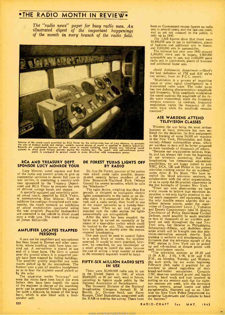
Interior of the sound coach provided by RCA Victor for the nation -wide tour of Lucy Monroe, to promote the sale of defense bonds and stamps, exhibits several phases of sound as applied to defense industries. Records are emphasixed because of their value in morale building, when played over industriel sound systems to offset peak fatigue periods during the working day. The coach, with self- contained power
plant, is equipped to project sound in every direction with tremendous power.
RCA AND TREASURY DEPT. SPONSOR LUCY MONROE TOUR
Lucy Monroe, noted soprano and first of the radio and concert artists to give up commercial activities to devote full time to war service, is conducting a country -wide tour sponsored by the Treasury Depart- ment and RCA Victor to promote the sale of defense savings bonds and stamps.
A specially equipped and colorfully paint- ed sound coach, supplied by RCA Victor, is accompanying Miss Monroe. Used to publicize the meetings throughout each com- munity, the coach contains an exhibition of sound amplification equipment aiding the war program. Powerful loudspeakers are concealed in the vehicle to direct sound over a wide area. The coach is in charge of James McCarville.
AMPLIFIER LOCATES TRAPPED PERSONS
A new use for amplifiers and microphones has been found in Europe and other coun- tries, where bombing raids have been car- ried out. A microphone is placed at one end of a large horn. The horn is moved over the ground where it is suspected peo- ple have been trapped by falling buildings. The amplifier greatly magnifies any weak voices picked up by the microphone. The listener uses a pair of sensitive headphones so as to hear the slightest sound picked up by the mike.
The apparatus works "two-way" and once the voices have been heard (or even before they have been heard) the voice of the engineer in charge of the searching party can be projected through the ground for quite a distance, by means of the large horn, which is also fitted with a loud- speaker unit.
520
DE FOREST TURNS LIGHTS OFF BY RADIO
Dr. Lee De Forest, inventor of the audion tube which made radio possible, demon- strated recently before members of the New Brunswick- Highland Park Defense Council his newest invention, which he calls the "blaekouter."
The radio device, weighing less than five pounds, is designed to extinguish electric lights automatically in the home or on dis- play signs. It is connected to the light cur- rent and a radio aerial, then tuned to one of the major networks on a twenty -four- hour basis. When an air raid signal is sounded over the radio station the lights automatically are extinguished.
After the alert has been sounded, the lights may be turned on manually or by means of a time -delay switch which could be hooked to the unit. This switch would turn the lights on shortly after the station resumed broadcasting.
One unit could be used to control lights in a whole block of stores, the inventor asserted. It would be more practical, how- ever, he remarked, for one storekeeper or a small group to install the units because the cost of wiring a large number of stores in the necessary sequence would be large.
FIFTY -SIX MILLION RADIO SETS IN USE
There were 56,000,000 radio sets in use in the United States in 1941, of which 30,600,000, or 86 per cent, were in homes, according to figures made public by the National Association of Broadcasters.
The Research Division of the National Broadcasting Company, through H. M. Seville, Jr., Division head, and Barry Rumple, Chief Statistician, cooperated with the NAB in making the survey. There have
been no Government census figures on radio sets in several years, and the last one made, and as yet not released to the public, is only up to 1940.
The NAB figures show that there were 16,400,000 sets in use in institutions, places of business and additional sets in homes, and 9,000,000 sets in automobiles.
The increase last year over 1940 showed 1,300,000 more sets in homes, 1,000,000 automobile sets in use, and 3,600,000 more radio sets in institutions, places of business and additional home sets.
Avoid dictionaries department : -Here's the best definition of FM and AM we've run across; from an F.C.C. report:
"Modulation is a process of imparting sound or other signal (intelligence) to a transmitted radio wave. The radio wave has two defining characteristics -amplitude and frequency. With amplitude modulation the sound controls the amplitude of the ra- dio wave transmitted, while the frequency remains constant. In contrast, frequency modulation varies the frequency of the radio wave while the amplitude remains constant."
AIR WARDENS ATTEND TELEVISION CLASSES
Winning the war being the most serious business at hand, television has now en- listed for the duration. Its first assignment is the training of some 54,000 air wardens in the New York, Philadelphia, and Sche- nectady- Albany metropolitan areas, which air wardens in turn will be better prepared to train hundreds of thousands of others.
"Because our organization believes firm- ly, and has always felt from the beginning of our television pioneering, that video broadcasting has tremendous educational possibilities, we are happy indeed to join NBC, RCA, GE and Philco in the present television training course for air wardens," states Allen B. Du Mont. "We have in- stalled Du Mont television receivers in collaboration with the other organizations, so as to equip the 84 precinct classrooms in the five boroughs of Greater New York.
"From our own observations we have every reason to believe that television in- struction is not only highly practical in sav- ing much manpower and equipment, but is the only feasible means whereby this ex- cellent defense course, under the super- vision of Commissioner Lewis J. Valentine and Deputy Commissioner John H. Morris, Coordinator of Police Department Civilian .
Defense, could possibly be made available to tens of thousands of air wardens scat- tered not only throughout the vast New York area, but likewise in Philadelphia, Schenectady -Albany, and doubtless other areas which will be brought into this tele- vision- instruction network shortly. Such training is uniform and simultaneous. It is fcrtunate that the television signals of the NBC station in New York can be picked up and rebroadcast at distant points with such satisfactory results.
"The television sessions at 10:30 and 11:30 A.M.; 3:00, 4:00, 8:00 and 9:00 P.M., on Monday, Tuesday and Wednes- day each week, for six weeks beginning February 23rd, make it practical for air wardens to attend regardless of their bread- and -butter occupations. Certainly NBC deserves unstinted praise and thanks for the hard work and cost involved in putting on six sessions each day for eight- een sessions per week, with the necessary actors, scenery, actual bombs and other paraphernalia, diagrams and so on. Like- wise the New York Police Department for assigning Lieutenants and Captains to head the lectures."
RADIO -CRAFT for MAY, 1942
a www.americanradiohistory.com

WHEN TWO MIKES BEAT ONE! Frank Forest, tenor on the "Double or
Nothing" show heard over KHJ- Mutual Don Lee Mondays 8:30 p.m. PWT, is in- debted to the Mutual engineer who sug- gested that he use two microphones to accommodate his voice range. One is placed in the usual place in front of the singer with the other one about 10 feet away. When Forest goes into a high note, microphone number one is closed and the other micro- phone is depended on to pick up his voice.
NEW DEVICES TEST AIRLINE SETS
Two new devices for testing aircraft radio equipment have been designed and produced by United Air Lines for use in service shops along its routes.
One of the devices, designed by H. N. Wilcox of the laboratory staff, is a vibration generator for testing radio equipment under conditions considerably in excess of tho, encountered in flight. An air- operated gen- erating unit with an electrical frequency control is connected with a test table which can be rotated through 3t0 degrees for inspection of equipment during test. A means is provided for increasing or decreasing the amplitude of vibration, with a maximum intensity of 3 g's for a 100 -pound load. The frequency of vibration is constant at 30 cycles per second.
The other device, designed by E. A. Jen- sen, also of the laboratory staff, is a signal generator for aligning and measuring the frequencies of all radio receivers carried aboard United's Mainliners. The equipment is made for the operation of 24 crystal - controlled frequencies but can be adapted to as many as 40. It has an output ranging from one millionth of a volt to one volt and is capable of modulation up to 100 per cent at six different audio frequencies.
NEW "SHAKE TEST" FOR RADIO: Here is United Alr Lines' newly- designed vibration generator for testing aircraft radio equipment under conditions considerably in excess of those encountered in flight.
THE RADIO MONTH IN REVIEW
NAVY BOMBER RADIOMAN AT WORK: The accompanying official U. S. Navy hoto shows the radio operator on the lob, aboard one of our Navy bombers. Radio today is tremendously important in all operations, especially where bombers are engaged on long flights. Radio keeps the plane in contact with the "home base' and conversations are also carried on between the various planes in the bombing squadron. In some cases the bombing plane checks on its objective by taking directional bearings on
broadcast or other stations operating in the enemy territory.
LAST RADIO -PHONOGRAPH COMES OFF RCA LINE
The last radio- phonograph for civilian use rolled off RCA Victor's Camden as- sembly line on Tuesday, April 7. It was also revealed that the final commercial ra- dio chassis to be built at the Company's Camden factory for the duration was com- pleted 50 days ahead of the deadline set by the War Production Board.
The WPB on March 7 ordered the man- ufacture of radins and phonographs for home use to be discontinued after April 22. A provision in this order permits the com- panies to complete the instruments on which they had begun assembly on or before \pril 22, under the limited production quota provided for in a previous order. However, with the completion of the last chassis on March 5 and its installation on April 7, all phonograph and cabinet assembly opera- tions at the Camden plant ceased that day.
According to Robert Shannon, president of the RCA Manufacturing Company, the WPB order did not find his company- un- preixi red. -
`As far back as September, 1939, when the Nazi hordes began to over -run the European continent, our Company's leaders foresaw that radio and sound would be called upon to play a more important role in our country's history than ever before.
"Long -range plans were laid then for the conversion of plants, machinerv, ma- terials, and man -power to our country's re- quirements as they would become needed."
By pushing its commercial radio work out of the way at the Camden plant weeks ahead of the WPB deadline, Mr. Shannon declared, the company gained valuable time in its conversion process. Immediately after the last radio -phonograph instrument was taken from the final assembly line, demoli- tion squads went into action in the first step toward converting the remaining fa- cilities of the radio plant at Camden to total production of radio and sound equipment for the armed forces.
RADIO -CRAFT for MAY. 1942
TIGHT SEAL BETWEEN IRON AND GLASS
Tight seals between iron and glass, eliminating the need for nickel and cobalt, critical war metals, for wires leading into certain types of vacuum tubes, are now being made with a new development of General Electric scientists. Dr. Albert W. Hull and Dr. Louis Navias, of the G -E Research Laboratory, have just been granted a patent for their invention.
Prom early days of the electric lamp, a problem of construction has been to make a tight seal between metal and glass. It is also involved in making radio tubes. Even with tubes in which the glass shell is re- placed by one of metal, the lead -in wires pass through glass insulating bushings.
Since nickel and cobalt (previously used for the purpose) are used in many ways for war equipment, and their supply is ex- tremely limited, the new invention of Dr. Hull and Dr. Navias is an important one, since for certain applications, it permits tight seals to glass without their use. They have devised a series of glass compositions which can be used with iron and certain iron alloys. One consists of 45 per cent silicon dioxide, 14 per cent potassium oxide, six per cent sodium oxide, 30 per cent lead oxide and five per cent calcium fluoride. The rate of expansion of these glasses is very close to that of iron.
In seals using these glasses a further and separately patented invention of Dr. Navias also proves useful: When a glass contain- ing lead is sealed in contact with iron, some of the lead atoms migrate from the glass into the metal. This weakens the joint, and may let air leak into the tube. Dr. Navias proposed placing a thin layer of lead -free glass directly over the metal, then sealing the lead -containing glass to that. The thin glass layer prevents the lead from reaching the iron, yet it is not thick enough to crack and let air in.
521
www.americanradiohistory.com
RADIO DEFENSE
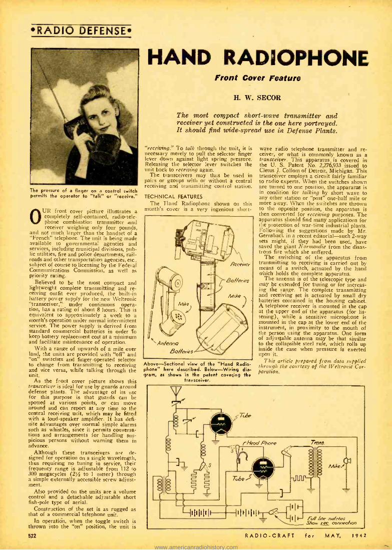
The pressure of a finger on a control switch permits the operator to "talk" or "receive."
R front cover picture illustrates a completely self -contained, radio-tele- phone phone combination transmitter .end receiver weighing only four pounds,
and not much larger than the handset of a "French" telephone. The unit is being made available to governmental agencies and services, including municipal divisions, pub- lic utilities, fire and police departments, rail- roads and other transportation agencies, etc.. subject of course to licensing by the Federal Communications Commission, as well as priority rating.
Believed to be the most compact and lightweight complete transmitting and re- ceiving outfit ever produced, the built -in battery power supply for the new Weltronic "transceiver, "" under continuous opera- tion, has a rating of about 8 hours. This is equivalent to approximately a week to a month's operation under normal intermittent service. The power supply is derived from standard commercial batteries in order 'to keep battery replacement cost at a minimum and facilitate maintenance of operation.
With a range of upwards of a mile over land, the units are provided with "off" and "on" switches and finger -operated selector to change from transmitting to receiving and vice versa, while talking through the unit.
As the front cover picture shows this transceiver is ideal for use by guards around defense plants. The advantage of its use for this purpose is that guards can be spotted at various points, or can move around and can report at any time to the central receiving unit, which may be fitted with a loud- speaker amplifier. It has defi- nite advantages over normal simple alarms such as whistles, since it permits conversa- tions and arrangements for handling sus- picious persons without warning them in advance.
Although these transceivers are de- signed for operation on a single wavelength, thus requiring no tuning in service, their frequency range is adjustable from 112 to 300 megacycles (2% to 1 meter) through a simple externally accessible screw adjust- ment.
Also provided on the units are a volume control and a detachable adjustable short fish -pole type of aerial.
Construction of the set is as rugged as that of a commercial telephone unit.
In operatidn, when the toggle switch is thrown into the "on" position, the unit is
HAND RADOPHONE Front Cover Feature
H. W. SECOR
The most compact short -wave transmitter and receiver yet constructed is the one here portrayed. It should find wide -spread use in Defense Plants.
"receiving." To talk through the unit, it is necessary merely to pull the selector finger lever down against light spring pressure. Releasing the selector lever switches the unit back to receiving again.
The transceivers may thus be used in pairs or groups with or without a central receiving and transmitting control station.
TECHNICAL FEATURES
The Hand Radiophone shown on this month's cover is a very ingenious short-
Above-Sectional view of the "Hand Radio- phone" here described. Below- Wiring dia- g am, as shown in the patent covering the
transceiver.
wave radio telephone transmitter and re- ceiver, or what is commonly known as a transceiver. This apparatus. is covered in the U. S. Patent No. 2,276,933 issued to Cletus J. Collom of Detroit, Michigan. This transceiver employs a circuit fairly familiar to radio experts. When the switches shown are turned to one position, the apparatus is in condition for talking by short wave to any other station or "post" one -half mile or more away. When the switches are thrown to the opposite position, the apparatus is then converted for receiving purposes. The apparatus should find many applications for Cie protection of war -time industrial plants. Following the suggestions made by Mr. t;crnsback in a recent editorial -such 2 -way sets might, if they had been used, have saved the giant Rrorrnandie from the disas- trous fire which she suffered.
The switching of the apparatus from transmitting to receiving is carried out by means of a switch, actuated by the hand which holds the complete apparatus.
The antenna is of the telescopic type and may be extended for tuning or for increas- ing the range. The complete transmitting and receiving set is actuated by small dry batteries contained in the housing cabinet. A telephone receiver is mounted in the cap at the upper end of the apparatus (for lis- tening), while a sensitive microphone is mounted in the cap at the lower end of the instrument, in proximity to the mouth of the person using the apparatus. One form of adjustable antenna may be that similar to the collapsible steel rule, which rolls up inside the case when pressure is exerted upon it.
This article prepared front data supplied through the courtesy of the Weltronic Cor- poration.
RADIO -CRAFT for MAY, 1942
www.americanradiohistory.com

RADIO DEFENSE
ri,n, to, U. .. er. 1, > ,..,i -..n,.
Left: -Col. A. Robert Ginsburgh recently led a group of Army officers on a visit to the Vultee Aircraft plant. Sgt. D. Symington is seen talking to C. A. Phillips, a Vultee employee, on the electrical installa Lion bench. Right: -The author soldering radio switch panel.
The RADIO MAN B. H. LEFTWICH Keeps 'em Flying
The excellent opportunities open to the Serviceman in the aircraft industry are explained by the author. Men aré needed, at good pay, for assembling radio sets for planes and installing them in the planes. Don't fail to read
Mr. Le f twich's article.
THE foreman turned from the blue- prints at his desk and faced me. I wondered if I had stuck my neck out again. But he laid a friendly hand on
my shoulder and grinned. "Tomorrow, Ed," he told me, "I'm mak-
ing you a lead -man." For a moment everything went haywire
all around me. Things began to whirl and swim about in mad confusion. While I grabbed the back of the foreman's chair to steady myself, something choked up inside of me. A few seconds ... and I came back to earth.
"Thanks, a lot, Jim," I managed to breathe, and the staccato pounding of the riveters in the next department almost drowned out my words. "I'll do the best job I can."
"I know you will, Ed. You'll have charge of all the soldering on oyir ships." Again, he grinned. "Now, fly into it and show me what you can do."
Sitting at my desk, going over my jobs for the night, I looked over my own crew .. , the crew of ex- servicemen, amateurs and electricians, whose work I was now responsible for in the tremendous bomber plant. I'd wanted this job.... Lord how I'd wanted it, worked for it and looked forward to it as a goal of real achievement.
It wasn't hard for me to look back, just a year ago, to the time when I'd first start- ed in the aircraft plant. Then, I wouldn't have dreamed of a job such as this. A few yards away, on my right, stood my super- visor, the same one I'd had when I started, and he knew all the answers.
A big, jolly ex -radio serviceman, who formerly owned his own shop, Ken was okay then, just as he is now. The night I started to work, Ken had said, "I've heard about you, Ed. You're one of the old - time servicemen, and I'm glad to have you
RADIO -CRAFT for MAY, I
here in Radio and Electrical Sub -assembly. Your radio knowledge will help you a lot, but you'll have to learn to do things our way, of course."
And did he put me through! Night after night, I sat at my bench learning to solder the way aircraft assemblies have to be soldered, and believe me that soldering has to be just about perfect. There were dozens of different assemblies, radio and electrical to wire, and these jobs were a long way from the auto -radios, midget broadcast sets, haywire transmitters and receivers I'd been wiring.
You see, aircraft equipment has to be right. It's a matter of life and death, and now that we are in the war, it means more than ever before.
Even to an old -time radio man, the many different jobs in our department looked complicated and confusing. I wondered if I'd ever be able to thoroughly master all of the different assemblies. You think that wiring tip a super -het is a tough job? I used to think so, too. But just wait until you see an aircraft assembly for the first time!
Ken put me through the mill ... and I liked it. Any man who likes to do a real job, one that he is proud of, would have liked it, and after a while my work began to stick and stopped coming back from In- spection department.
In the modern aircraft plant, the radio serviceman can be easily trained to fit in like the cellophane wrapper on a cigarette pack. From his former experience, he knows how to solder, to wire and install equipment. If he likes to build equipment, Sub -assembly is where he belongs. If he'd rather install wiring and equipment, there are places for him on the Final- assembly line. Then, there are Testing and Inspection departments where the radio serviceman
942
will surely feel perfectly at home. Almost without exception, our Inspectors
are hams and former servicemen. Our fore- man is an ex -navy radio operator and speaks our own language.
Working conditions in an aircraft plant are ideal, and even though our war pro- gram calls for intensive all -hour produc- tion, officials realize the importance of the human element. These things are never neglected for a moment, and there is full co- operation between the company and the employees. Everything possible is done to promote safe, sanitary and harmonious working conditions.
Personal problems which arise from time to time are taken care of without delay and in a manner which takes into considera- tion the personality of the particular work- er. The amazing progress of the American aircraft industry is largely due to this al- most unbelievable spirit of co- operation, which I do not hesitate to say was present long before we got into the war. Aircraft officials never take the "know -it -all" atti- tude. Rather, their viewpoint is that, "5000 heads are better than one."
In our plant there are from ten to twenty - five cash awards made each month to em- ployees for original devices which do a cer- tain job better and quicker.
It is certainly advisable that a great num- ber of servicemen stay on their jobs to "keep 'em playing," because Uncle Sam wants the public to know about things, especially in cases of emergency, but there are many jobs open in the aircraft field for the radio serviceman.
After the war, the aircraft industry will come into its own, in a big way, and thousands of responsible jobs will be made here for the radio serviceman, because
you can't "keep 'em flying" without radio equipment!
www.americanradiohistory.com

SERVICING
"WAR- TIME" SERVICING
THE radio serviceman on the home iront is going to be called on to repair sets for which exact replacement parts are no longer obtainable. To many men
t this will mean the exercise of an ingenuity which in former years might have been lacking and unused. The most common question which arises in the minds of radio men is the effect of using a condenser which is larger or smaller in capacity than the original.
Let's take a practical example. A certain receiver has a power supply using an 8 mf. input filter, followed by a field coil serving as a choke. The second filter condenser is also an 8 mf. unit. Now, the voltage rating of the original units is 450 volts. A service- man has a dual condenser having a capacity of 16-8 mfs. at 450 volts. How should he connect the replacement condenser? It is assumed that the choke is in the positive leg of the circuit.
We know, from radio theory, that the peak current to the rectifier tube will be a function of the first filter condenser ca- pacity and other factors. Therefore, we appreciate that it is not wise to install a larger unit capacity than the original for the first filter condenser than about 10 mf. (plus 20% roughly). We therefore take the 8 mf. section of our replacement and connect it from the rectifier filament to ground and the second condenser of 16 mf. from B plus to ground. The 16 mf. unit results in better filtering and gives slightly improved bass response since the lower audio frequencies are more readily shunted to ground through the lower reactance of the 16 mf. in comparison with the original 8 mf. condenser. A safe rule to follow is that the rating of the condenser used as a replacement should equal the voltage rating of the original, but should never be less than the original. It may, on the other hand, exceed in voltage rating the original unit. The capacity of the first filter condenser should not be increased by more than 20 per cent over the original for the first filter input condenser and for grid coupling condensers or condensers in A.V.C. cir- cuits. Plate return or screen return by -pass condensers are not critical and may have larger capacities than the original, but the voltage rule given above must always apply.
In many cases smaller capacities than the original will be available. Suppose, for example, that we had a triple section condenser of 4-4-8 mf. (Fig. 3) and wanted to use it in the above power supply. The voltage rating of the condensers is 450 volts. By oining the two 4 mf. units to- gether and connecting to the rectifier fila- ment and ground we have the first filter condenser and the 8 mf. unit takes care of the B plus. The 4 mf. unit was installed along with its twin at the input for the reason that if one 4 mf. unit opens up the set will still play with the remaining one. Of course, there is also the danger that if one unit shorts the other will be worth- less, but if the first condenser shorted the power supply would be inoperative if the 8 mf. unit were used -anyhow. 524
WILLARD MOODY
Re men/
B+ 1_11 TTTT TTTT y 4
1.:"-':-.p5 MI' Oo6 Me I 400 V.
400 V r > > > fg. S 4/ M! S 28
F,g .3
= 025 .05 400V. 200 v.
F,9 7 each
: li) 1200Y. 600 V.
A--,9 8 eaten
'f/y lO
C, C Aobfd cvvoa,/y ca/J jj' and V4 ° %
Fewer sizes of replacement condensers and resistors are available to the "wartime" Serviceman. In many cases he will find it necessary to substitute a couple of low- voltage condensers, connected in series, in place of a single condenser of higher voltage rating. Many interesting and practical prob- lems concerning substitute resistors and condensers are discussed by the author and shown in the
accompanying diagrams.
How may the Serviceman safely substitute low voltage condensers for those of higher rating? How does one calculate the relative carrying capacity of substi- tute resistors? These and many other questions fac- ing the War -Time Service- man are answered in the accompanying timely article
by Mr. Moody.
If we had had a number of condensers, each of 2 mf. capacity and 450 volt rating, it would have been perfectly feasible if not economical, to connect a number of them in parallel. (Fig. 4) Two 4 mf. con- densers in parallel are equivalent to one 8 mf. condenser. Two 16 tuf. condensers in parallel are equivalent to one 32 mf. condenser.
Probably the most common trouble will be in getting condensers of odd sizes in the paper series. That is, a condenser of .006 mf. may be difficult to get. (Fig. 5) In such cases a .005 mf. in parallel with .001 mf. will give the necessary capacity. If a .012 mf. unit is needed for a critical tone control circuit, two .006 mf. units can be substituted.
In certain cases a .5 mf. condenser of 400 volts is needed to withstand the mo- mentary peak voltage which is present in a circuit when the current is first turned on. The operating voltage may be only 160 or 170 volts when the set is operating, (Fig. 6) but a 200 volt condenser can't be used. When a circuit such as this is en- countered, it is possible in many cases to shunt a resistor across the condenser to limit the voltage peak. As the voltage is high when the set is turned on, the current in the resistor will be high and the effect of the voltage will be cut down. The re- sistor can be determined experimentally for a given set, by connecting a high re- sistance voltmeter (5,000 ohms per volt or better) across the condenser. The peak voltage can be measured with a test ca- pacity in the circuit and then a resistor can be tried and a new measurement made.
The capacity of two condensers in series is given by the formula,
1 1 1 -- -F- -.... etc. C G Ce
For example, two .05 mf. condensers of 200 volts hooked in series would be equiva- lent to a .025 mf. condenser rated at 400 volts. (Fig. 7) Two .01 mf. condensers rated at 200 volts each would be equiva- lent, if hooked in series, to a .005 mf. con- denser rated at 400 volts. (The voltage strain is divided between the two con- densers.)
In the automobile sets there are con- densers across the high voltage secondary which have small capacities but high volt- age ratings. Where there is sufficient space it is permissible to hook a couple of 600 volt condensers in series (Fig. 8) to get 1200 volt equivalent ratings.
RESISTORS
Suppose that we have a cathode circuit requiring a 400 ohm resistor rated at 5 watts. We have on hand a 100 ohm unit rated at a % watt and a 300 ohm unit rated at 2 watts. We are to assume that the original unit in the circuit is a 5 watt unit, but that 2.5 watts is the actual power in the resistor. Since the power is 2.5 watts and the resistance is 400 ohms, the current is
RADIO -CRAFT for MAY. 1942
www.americanradiohistory.com
From the formula P = PR, P
P = - and I = V P/R R
Then, I = V 2.5/400 = .079 ampere
.079 x .079 X 100 = .625 watt .079 X .079 X 300 = 1.875 watt
Therefore, the-Y2-watt would need to be changed to a 1- wat>resistor, or 2 -watt re- sistor- depending on the ventilation. The 300 ohm unit would need to have a 4 or 5 watt rating. A wattage rating equal to twice the normal circuit power is standard, com- mercial practice.
A 6F5 tube requires a 100,000 ohm plate load resistor for a certain type operation of the tube. The original load was a 100,000 ohm ,/2 watt type. Can a 1 watt carbon type be used as a replacement ? Yes, since the increase is in the right direction towards higher rather than towards lower wattage. Can a wire -wound type be used? Yes, since the inductance of such a unit,, even though non -inductively wound, would be negligible (audio).
I have a special form of line cord which has a tapped resistance of 40 ohms from one end. The total series resistance of the cord is 160 ohms. The current in the circuit is .3 ampere (typical A.C.-D.C. heater circuit). I have on hand a 40 ohm 10 watt resistor and a 120 ohm wirewound resistor having a rating of 20 watts. Can these resistors be used in place of the original line cord, pro- vided the job of installation is done in a rugged, workmanlike manner?
First of all, the power in the resistor is for 120 ohms at .3 ampere,
P =PR =.3 X .3 X 120 =10.8 watts The power in the. 40 ohm resistance is,
P= I'R= .3X.3X40 =3.6 watts Thus, it is definitely established that the 20 watt, 120 ohm resistor and the 10 watt, 40 ohm resistor could safely be used as a re- placement for the special line cord.
Suppose that we have two 1 watt re- sistors of 300 ohms and wish to know if they may be substituted for a resistor of 600 ohms and 2 watt rating. The power in the circuit is 1 watt. Since the power is 1
watt, the current is I = V P/R = V1/600 = .04 ampere
then 300 X .04 X .04 = .48 watt X2 .96 watt total
The resistors, obviously, could safely be used.
If we have two 250,000 ohm resistors and one 50,000 ohm resistor, what is the net resistance if the resistors are all connected in parallel? From the formula,
1 1 1 1 - -+ --F- RN R, R, R.
1
RN = .000004 -I- .000004 + .00002 1
RN = .000024 1
RN = .000028
RN = 35,714 ohms I have an audio transformer with a
burned out primary. The unit is used to couple a 56 plate to two type 45 tubes in push -pull. How may I make a repair which will give fairly good service without re- placement or redesign? A simple way of doing it is to shunt a 100,000 ohm 1 watt resistor (Fig. 9) across the primary and to connect a .05 mfd. 400 volt condenser from the 56 plate to one of the 45 grids. By auto -transformer action, the second 45 grid will receive an audio signal. Since the pri-
t
mary of the transformer is open, the sec- ondary impedance will be higher than it should be. Therefore, shunt a 200,000 ohm resistor across each half of the secondary.
I have a burned out speaker field having a resistance of 500 ohms. The set is an A.C.-D.C. job using a 25Z5 rectifier. The only replacement i can get is a 3,000 ohm (field) speaker. How should I connect the set?
Substituting a resistor of 500 ohms for the speaker field, a voltage measurement is made on the set and a reading of 16.5 volts is obtained. The power in the field must, then, be
E' 16.5' P = -_ = .5245 watts
R 500 The power in the 3000 ohm field. is
E' 100' P = = = 3.3 watts
R 3000 The current is
I = V P/R = V 3.3/3000 = .0332 amp. The current in S00 ohms is
E 16.5 I = - =- =.033 amp.
R 500
The currents are the same, but the powers are widely different.
Since the original speaker field power was .5245 watts and the speaker, having a 3000 ohm field, draws an excessive amount of current, what is to be done?
Adding another rectifier tube would be the only practical answer. At 100 volts out- put, the field would receive more energy than the original field received from its power source. However, the new speaker would have more reserve strength and greater power -handling capability% so that better tone would probably result when the heavier speaker field is used.
A choke coil would be used in place of the original field or a resistor could be used. If the resistor is employed, additional filter capacity will be needed to keep the hum - level down, due to loss of filtering action with the speaker field removed, or the choke inductance replaced by the low impedance resistor. The choke or field would have a high reactance and high impedance for A.C. -much greater than that of a resistor.
A quick way of checking the relative ef- ficacy of the filter with resistance of 500 ohms in place of the S00 ohm field would be to use a vacuum -tube voltmeter or A.C. voltmeter across the second filter conden- ser. A voltage measurement of A.C. is first made, (500 ohm choke) A.C. voltage being checked across the first and second filter condensers. The 500 ohm resistor is then substituted and the A.C. voltage across first and second filter condensers is again checked. The second and first filter con- densers are then shunted with additional capacity until the A.C. voltage appearing across the second filter condenser is no larger than the voltage which appears across the second filter condenser when the choke is used.
In some cases it may be necessary, due to the impossibility of obtaining a special transformer, to substitute a standard power transformer for a tapped transformer. Some sets, not many, use a 1 -V rectifier and tapped secondary winding on the trans- former, A type 80 rectifier can be substi- tuted, with an improvement in hum reduc- tion since for the same amount of capacity the full wave rectifier system has less hum output. The hum frequency is twice the power supply frequency, or 60 X 2 is 120 cycles. Condensers have j4 as much react- ance at 120 as at 60 and so they are more efficient by -pass agents.
RADIO -CRAFT for MAY, 1942
SERVICING
MR JOHN GEO. COLEMAN
tenance of Westchester ,t
Radio Main on Ave.. Mt. Vernon. N.
110 Mt. Vern
products have always been
f. highest quality. those mu h
plan has helped tile get
needed pieces of testing equipment
WHERE YOU FIND
nATIOnALunion YOU FIND BETTER RADIO SERVICE
BATTERIES
CONDENSERS Transmitting tubes, panel
lamps, cathode ray tubes, ex- citer lamps, sound equipment, photo electric cells, sound ac- cessories. dry batteries, flash light bulbs.
NATIONAL UNION invites .. .
All radio service dealers to enjoy the benefits of the N. U. Shop Equipment Plan. The latest in tube testers and test equipment are available to you ... prompt delivery. More than 60,000 corn - pleted deals prove the success of this plan. Investigate now.
NATIONAL unión RADIO6
57 STATE ST.,fEWARH.A.J.
525
www.americanradiohistory.com

SER "ii`iNG
The photos above show front and rear views of the home -made line voltage "booster."
y
A LINE VOLTAGE -BOOSTER With 4 -Range A.C. Voltmeter
In many localities the line voltage rises and falls periodically, making the testing of the radio set a very dubious matter. The line voltage "booster" here described
will be found most useful for correcting the voltage to the proper value.
(O.vA,r.
LIONEL HAID
i.OV(i,yc Souer-
Je r.
N the writer's locality (Indiana) we have had considerable trouble in the rural districts with intermittent operating sets. The steady flow of sets into our
service shop with this complaint seemed to indicate that there was some trouble in the locality where these sets were used, especially when they would play perfectly for hours on our bench. To arrive at the source of the trouble, periodic checks of the line voltage in the customer's homes throughout the day were made, and we found that at certain times when there was the least load on the lines, the line voltage soared as high as 135 volts.
As it was impossible to work on the receivers in the home it was decided that we should design and build a suitable in- strument for boosting the normal city line voltage to that equal to what the set must operate on. As we had no good A.C. volt- meter in the shop it was planned to combine
uu.suo 3J
Muir/P[KR 50,
Wiring diagram for the easily -built line voltage "booster" is
shown above.
Right -Panel layout diagram for the volt-
age "booster."
Wi.etG/kt
[4.urr0
TiP,AMh3
the two instruments. The construction of the instrument is here described.
The first thing to do is to secure all of the necessary parts. Next, lay out and drill
,..50 the front panel as in figure 1. Mount the auto -transformer on the chassis deck, as far back as it will go. Then fasten the deck to the panel by means of two 6 -32 round- head screws. Next mount all of the remain- ing parts on the panel. We are now ready to begin the wiring. A much neater job will be had, if all of the wires are grouped and tied with string. The multipliers furnished with the A.C. voltmeter come mounted in a perforated metal box 6$" long, 5'' /z" wide and 3%" deep. This box is bolted with small screws to the back of the Bud metal cabinet. The meter selector switch is con- nected to the terminals on the multiplier
.o
t.0
526 RADIO -CRAFT for MAY, 1942
www.americanradiohistory.com
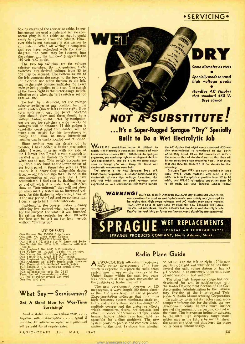
box by means of the four -wire cable. In our instrument we used a male and female con- nector plug in this cable, so that it could easily be removed from the cabinet. How- ever this is not necessary if one desires to eliminate it. When all wiring is completed and you have rechecked with the circuit diagram, the panel may be fastened into the cabinet and the line cord plugged in the 110 volt A.C. outlet.
The two top switches are the voltage selector switches. By manipulating these switches, any desired voltage from 85 to 150 may be secured. The bottom switch at the left connects the meter to the tip -jacks, for external use when thrown to the left, and in the right position indicates the exact voltage being applied to the set. The switch at the lower right is the meter -range switch, effective only when the left switch is set for external use.
To test the instrument, set the voltage selector switches at any position, turn the meter switch (lower left) to the right. Now turn instrument on ; the panel indicator light should glow and there should be a voltage reading on the meter. By manipulat- ing the two top switches a wide variety of voltages will be obtained. If this gadget is carefully constructed the builder will be more than repaid for his investment in money and labor, as many intermittent troubles can be easily located and remedied.
Since sending you the details of the booster, I have added a flasher mechanism which I wired in series with one side of the 110 volt line. I used a rotary switch in parallel with the flasher to "short" it out when not in use. This switch accounts for the large black knob at the lower center of the front panel in these later pictures. The flasher is a heavy -duty adjustable device from an old electric sign that I found in the conglomeration of odd parts that I have accumulated. I find that by flashing the set on and off while it is under test, will often show up "intermittents" that will not show up when merely tested on an increased vol- tage. As this flasher is adjustable, I can set it for any period of off and on contacts that I desire, up to half minute intervals.
Incidentally, the booster makes a dandy soldering iron control when not being used for the purpose for which it was intended. By setting the controls for about 80 volts the iron can be left on for long periods without "burning up ".
LIST OF PARTS One Stancor No. P -5068 Auto-former One Bud No. C -993 Metal Cabinet One Bud No. CB -522 Chassis Deck One Bud No. JL -1698F 110 V. Lamp and Socket One Triplett No. 337A A.C. voltmeter with mul-
tipliers One Amphenol No. 61 -F A.C. receptacle Two Yaxley No. 32112J 12 -point tap switches One Yaxley No. 32151 5 -point tap switch One Yaxley No. 32227 S.P.D.T. switch One Amphenol No. MPM4 male cable connector One Amphenol No. MPF4 female cable connector Two Centralab 1-5 numbered switch plates Two Centralab 1-10 numbered switch plates One toggle switch Two Amphenol tip jacks No. 78 -1P Three feet of four-conductor cable Six feet of rubber- covered line cord One line cord ping
What Say- Servicemen?
Got A Good Idea for War -Time Servicing?
Send a sketch .... we redraw them .... together with a description . . . . typed if possible. All articles accepted and published will be paid for at regular rates.
SERVICING
Same diameter as wets
Specially made to stand high voltage peaks
Handles AC ripples that standard 450 V.
Drys cannot
SUBSTITUTE' ...It's a Super- Rugged Sprague "Dry" Specially
Built to Do a Wet Electrolytic Job
WARTIME restrictions make it difficult to supply wet electrolytic condensers because of their aluminum thread -neck cans -but, thanks to Sprague engineers, you can keep right on making wet electro- lytic replacements, and do it with the some assur- once as though you were using the finest wet electrolytic condensers ever built.
The answer is the new Sprague Type WR Replacement Capacitor -a tubular cardboard dry electrolytic of very high voltage formation. Not only will WR's stand the peak voltages often impressed on wet electrolytics, but they'll handle
the AC ripples that might cause standard 450 -volt dry electrolytics to overheat to the point where they break down. The diameter of WR's is the some as that of standard wets so that they will fit the screw -type can mounting holes. Their metal feet con then be soldered to the chassis for firm mounting.
Sprague Type WR's are now available in three sizes -WR -8 which replaces wets from 4 to 8 mfds.; WR -I6 to replace capacities from 12 to 18 mfds., and WR -25 to replace capacities from 20 to 40 mfds. Ask your Sprague jobber today!
WARNING! Don't be fooled! Although standard dry electrolytic condensers can sometimes be used as wet replacements, your safety margin is apt to be mighty thin. High surge voltages and AC ripples may cause trouble. That's why it pays to ploy safe by using the new Sprague WR Types. They're not substitutes. They're actually built to do a wet electrolytic job. They're the real thing as for as performance and durability are concerned.
E(SPECIAL WR TUBULAR DRYS)
WET REPLACEMENTS
SPRAGUE PRODUCTS COMPANY, North Adams, Mass.
Radio Plane Guide
ATWO- COURSE ultra -high frequency radio range development of a type
which is expected to replace the radio beam system now in use on the airways of the United States within the next few years was described at the winter convention of the Institute of Radio Engineers.
The new development operates on 125 megacycles, a wave length 400 times short- er than the wave length in use at present. Experimentation indicates that this ultra high frequency system eliminates static en- tirely and greatly diminishes the danger of multiple courses and the distortive effects which mountains, rivers, ore deposits and other influences of terrain exert upon radio beams, factors which have been held re- sponsible for airline accidents. The new system provides precise and complete infor- mation to the pilot. I shows him whether
RADIO -CRAFT for MAY, I942
or not he is to the left or right of his cor- rect line of flight and whether he has flown beyond the radio range station or has not yet reached it, an extremely important point of information in bad weather.
The ultra high f requency range has been developed for and in collaboration with the Radio Development Section of the Civil Aeronautics Administration by the Labora- tory Division of the International Tele- phone & Radio Manufacturing Corporation.
In addition to its safety factors and more complete information for the pilots, the new development points the way much further toward the automatic gyroscopic control of the plane. The instrument indicator actuated by the ultra high frequency range trans- mitter may in the future be used to direct the automatic pilot and thus keep the plane on its course automatically.
527
www.americanradiohistory.com
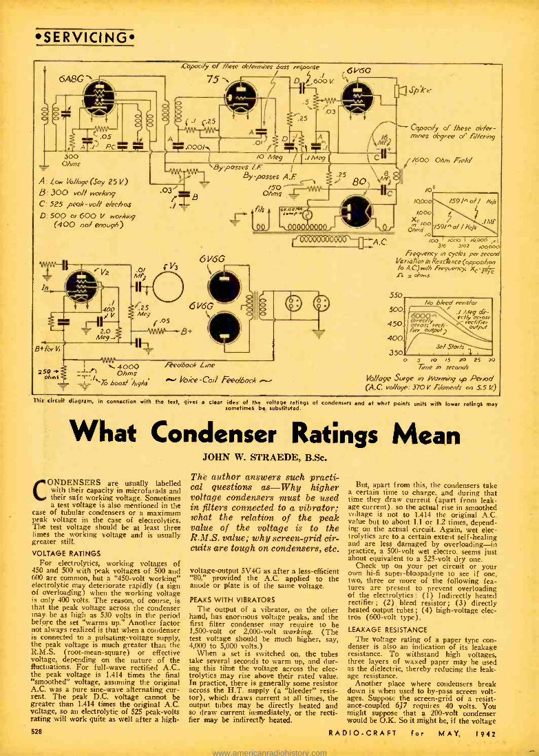
SERVICING
6A8G
J 1
1
C .05 AT/ PCT.= . vim
Cgoacv'/y of /hese of./ermass bass response
751 D, 6610 V.
k-I
II r03 (./ 4-.25
11111
212.000/s\
.5
.25
DI;/ A
/ T) 1 T.l 300
Ohms
A: Low 1/0/loge (Soy 250 8: 300 vo// working
C: 525 peak -rob' eleek s
D 500 or 600 V workv/g (400 no/ enough)
2.0 Mey
O/ AO)
/O Meg ./ Mcg 1
6,
i' V3
1.25 Meg
r.05
B+ for Vi
250 ohms
`By posses /.F. By posses A.F
O/5.n0
6V6G ` 6 V6
f//s
A.C.
-h 4000 Ohms
1-11.-J"-7.3 boos/ high;
Feedback Line
Voree -Coil Feedback
Spk/-
Copocdy of /hese 0'e/er- mines degree oc /lerin9
¡/600 Ohm Field
/0 /0000
lß00 , c /00
Ohms /o
/00 I /000 I /0.000 ,. 3/6 3/62 pt000
Frequency in cycks pe, second Variation in Reactance (oppose /ion 10 A.C)wi /h Freguenc/c Xc.=2n c fi c ohms
/59/^a// Ik/r
.iaiP 159/. a/ /ifc/s
550
500
450
400
350
No bleed res/s/or 1 ./ Meg air - ecJ /y ocrosr x rec./ f,er
ouJpu/ dree /y \ across tech - fier output)
Se/ S /arts
o S /o /5 20 25 30 Time in seconds
Vo//vge Surge In Worming up Peréod (A.C. vo / %ge: 370V / kmenls on 5.5 V)
TMs circul diagram. in connection with the teat, gives a clear idea of the voltage ratings of condensers and at what points units with Tower ratings may sometimes be substituted.
What Condenser Ratings Mean
CONDENSERS are usually labelled with their capacity in microfarads and their safe working voltage. Sometimes a test voltage is also mentioned in the
case of tubular condensers or a maximum peak voltage in the case of electrolytics. The test voltage should be at least three rimes the working voltage and is usually greater still.
VOLTAGE RATINGS For electrolytics, working voltages of
450 and 500 with peak voltages of 500 and 600 are common, but a "450 -volt working" electrolytic may deteriorate rapidly (a sign of overloading) when the working voltage is only 400 volts. The reason, of course, is that the peak voltage across the condenser may be as high as 530 volts in the period before the set "warms up." Another factor not always realized is that when a condenser is connected to a pulsating -voltage supply, the peak voltage is much greater than the R.M.S. (root- mean -square) or effective voltage, depending on the nature of the fluctuations. For full -wave rectified A.C., the peak voltage is 1.414 times the final "smoothed" voltage, assuming the original A.C. was a pure sine -wave alternating cur- rent. The peak D.C. voltage cannot be greater than 1.414 times the original A.C. vcltage, so an electrolytic of 525 peak -volts rating will work quite as well after a high-
528
JOHN W. STRAEDE, B.Sc.
The author answers such practi- cal questions as -Why higher voltage condensers must be used in filters connected to a vibrator; what the relation of the peak value of the voltage is to the R.M.S. value; why screen -grid dr- cuits are tough on condensers, etc.
voltage- output 5V4G as after a less -efficient "80," provided the A.C. applied to the anode or plate is of the same voltage.
PEAKS WITH VIBRATORS The output of a vibrator, on the other
hand, has enormous voltage peaks, and the first filter condenser may require to be 1,500 -volt or 2,000 -volt working. (The test voltage should be much higher, say, 4,000 to 5,000 volts.)
When a set is switched on, the tubes take several seconds to warm up, and dur- ing this time the voltage across the elec- trolytics may rise above their rated value. In practice, there is generally some resistor across the H.T. supply (a "bleeder" resis- tor), which draws current at all times, the output tubes may be directly heated and so draw current immediately, or the recti- fier may be indirectly heated.
But, apart from this, the condensers take a certain time to charge, and during that time they draw current (apart from leak- age current). so the actual rise in smoothed vr,ltage is not to 1.414 the original A.C. value but to about 1.1 or 1.2 times, depend- ing on the actual circuit. Again, wet elec- trolytics are to a certain extent self -healing and are less damaged by overloading -in practice, a 500 -volt wet electro. seems just about equivalent to a 525 -volt dry one.
Check up on your pet circuit or your own hi -fi super- bloopadync to see if one, two, three or more of the following fea- tures are present to prevent overloading of the electrolytics: (1) Indirectly heated rectifier ; (2) bleed resistor ; (3) directly heated output tubes; (4) high -voltage elec- tros (600 -volt type).
LEAKAGE RESISTANCE The voltage rating of a paper type con-
denser is also an indication of its leakage resistance. To withstand high voltages, three layers of waxed paper may be used as the dielectric, thereby reducing the leak- age resistance.
Another place where condensers break down is when used to by -pass screen volt- ages. Suppose the screen -grid of a resist- ance- coupled 6J7 requires 40 volts. You might suppose that a 200 -volt condenser would be O.K. So it might be, if the voltage
RADIO -CRAFT for MAY, 1942
www.americanradiohistory.com

came from a divider but if a dropping re- sistor is employed, then the condenser will certainly break down, because there is no voltage drop across the resistor when the set is switched on (and the 6J7 is cold), and the full H.T. voltage (then at its high- est, say, 500 volts) is across the screen by -pass condenser.
Sometimes condensers are connected in series to increase the voltage rating. This is very satisfactory in the case of wet electrolytics. For other types, bleeder re- sistances (about .1 meg. 1 -watt or 25 meg.
-watt) should be connected across each condenser to equalize the voltages. The catch, of course, is that if two equal con- densers are connected in series, the capacity is halved. Two 8 mf. 500 -volt condensers in series give a 4 mf. 1,000 -volt combina- tion.
CAPACITY RATING The use of a condenser depends on its
ability to store small amounts of elec- tricity, the amount stored depending on the voltage across the condenser and its capacity. We say that A.C. passes through a condenser -what really happens is that the charging and discharging of the con- denser permits the A.C. to keep flowing. D.C. (apart from a momentary surge, when the condenser becomes charged) does not pass through a condenser, so a common use of a condenser is to separate A.C. from D.C. Smoothing condensers across the H.T. supply by -pass the A.C. portions or the "ripple." The D.C. passes to the set.
The "reactance" or opposition of a con- denser to A.C. depends on the size of the condenser and the frequency or rate of variation of the A.C.
To separate A.C. and D.C., the condenser should be as large as possible. In practice there are limits, the physical size and the leakage generally increasing with capacity.
RADIO FREQUENCY High - frequency alternating currents
(R.F.) pass more readily than low -fre- quency (A.F.), so a condenser may be used to separate them. The size of the condenser here is important. If too large. too much A.F. gets through with the R.F. If too small, only part of the R.F. gets through, the remainder continuing with the A.F. In other words, there is always an "optimum size." A classical example of this is the condenser across the grid -leak in a grid detector circuit. For many years this was .00025 mf. which by- passed some of the higher audio- frequency signals. When the demand for quality slowly arose, like some dinosaur dragging itself out of the primeval mud, people began to demand these "highs" and the condenser was reduced to about .0001 mf. with a slight loss of volume, because part of the R.F. did not "get through."
RESISTANCE -CAPACITY COUPLING Because the reactance of a condenser
varies with frequency, resistance -capacity coupling between tubes tends to weaken the low notes. The actual loss at any frequency depends on the size of the coupling con- denser and the size of the grid resistor. The product of these two values (one in mfd., the other in megohms) gives an indication of the fidelity. The reciprocal of this prod- uct indicates the frequency at which re- sponse starts to fall off. (The response is approximately 3 db. down at a frequency six times the reciprocal, e.g., if C = .002 mfd., R = .5 meg., then the reciprocal is 1,000. The response is 3 db. down at about 150 c /s.) The circuit shown has a total loss of less than 1 db. at 20 c /s. from diode load to output, excluding speaker losses. - Reproduced through the courtesy of The Australasian Radio World, -
RADIO -CRAFT for MAY,
SERVICING
Now more than ever the jobber and service man must protect the standing which he has built. Condenser replacements account for about 40% of all radio repair jobs. Dependable condensers are therefore essential to the building of the utmost in customer satisfaction and in holding your clientele.
CONTINUOUS DEPENDABLE SERVICE For 21 years the manufacturers of POLYMET electrolytic and by- pass condensers have striven to improve quality and service.
Add to this a liberal and reasonable mark -up and the fact that no fly -by -night "bargain catalogs" can undersell you on POLYMET. You're protected, your customer is satisfied, your profits and volume increase. Were conserving vital defense materials by limiting sixes to those most universally used. These will practically every need, repairing larger electrolytics when proper capacity and voltage are used.
Complete listing of available types and prices will be forwarded upon request.
OLYMET CONDENSER CO.
DIATHERMY MACHINE USED BY SPIES
The use of short -wave diathermy ma- chines (of the type used by physicians for treating human ailments) by spies in war- time was described in considerable detail by H. Gernsback in his editorial in this magazine for May, 1940, page 645. In that article Mr. Gernsback also described an effective means for shielding the short - wave diathermy apparatus, so that it could not radiate electrical waves.
This editorial also pointed out that short- wave diathermy machines had been known to cause a radio disturbance 3,000 miles away and even further.
In a recent feature article published in the New York Daily Mirror, all of these facts are once more brought to the atten- tion of the public. The claim is made by this newspaper that a checkup by govern- ment agents has shown that Jap "Fifth Columnists" were using a whole series of these diathermy machines to transmit data on ship sailings, etc., to Japan. The article also claims that a very ingenious scheme was utilized to synchronize a dozen or more of these machines, so that they would all operate as one powerful transmitter, and at the same time make it much more difficult for F.B.I. radio listeners to locate exactly the origin of the secret signals.
One thing is certain -our government authorities should pass a law requiring that all short -wave diathermy machines be licensed, or else carefully and minutely checked up by F.C.C. inspectors, every machine of this type to be placed within a metal shielding cage, or else a room whose walls are covered with wire mesh or screen, and the screen thoroughly grounded.
It is interesting to point out that investi- gations made a few years ago showed that it is not sufficient to place a single wire - screen cage around such a diathermy ma- chine, but that to positively eliminate any radiation of radio waves from the appara- tus, that it is necessary to use two wire - mesh screens or cages, the two cages or screens separated a few inches apart, and both of them thoroughly grounded.
1942
4 STANDARD TYPES of Aaxperite Regulators replace over
s of AC -DC Ballast Tubes now in u
rites are real REGULATORS ... Automatic Starting Resistor initial surge and saves pilot
. . Ask Your Jobber.
WAY TO REPLACE
BALLII5T5 WRITE FOR REPLACEMENT CHART
AMPERITE 6. so uoow, law rose a r
RADIO TECHNOLOGY RCA instilutee offer an intensive emiree of high standard embracing ell phases of Radio and Television. Practical training with modem auipment at New York and Chicago scheMi.
Also specialised courses to Aviation Communi- cations, Radin Servicing and Commercial Oper- ating. For Free Catalog write Dept. 11C-42.
RCA INSTITUTES, Inc. A Radio Corporation of America Service
75 Varick St.. New York. 1154 Merchandise Mart, Chiang*
529
www.americanradiohistory.com
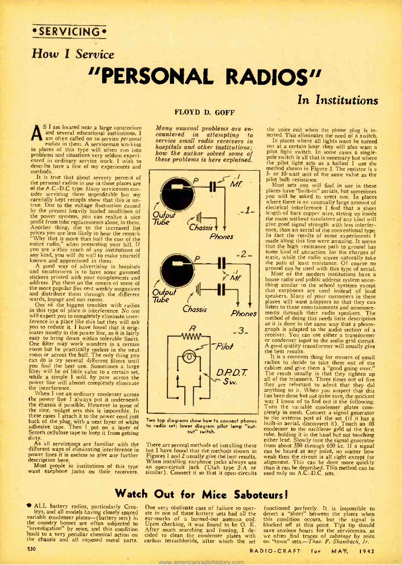
SERVICING
How I Service
"PERSONAL RADIOS"
As I am located near a large sanatorium and several educational institutions, I am often called on to service personal radios in them. A serviceman working
in places of this type will often run into problems and situations very seldom experi- enced in ordinary service work. I wish to describe here a few of my experiences and methods.
It is true that about seventy percent of the personal radios in use in these places are of the A.C. -D.C. type. Many servicemen con- sider servicing them unprofitable but my carefully kept records show that this is un- true. Due to the voltage fluctuation caused by the present heavily loaded conditions of the power systems, you can realize a nice profit from tube replacements alone, in them. Another thing, due to the increased list prices you are less likely to hear the remark "Why that is more than half the cost of the entire radio," when presenting your bill. If you are within reach of any institutions of any kind, you will do well to make yourself known and appreciated in them.
A good way of advertising in hospitals and sanatoriums is to have some gummed stickers printed with your complements and address. Put them on the covers of some of the more popular five cent weekly magazines and distribute them through the .different wards, lounge and sun rooms.
One of the biggest troubles with radios in this type of place is interference. No one will expect you to completely eliminate inter- ference in a place like this but they will ask you to reduce it. I have found that it orig- inates mostly in the power line, so it is fairly easy to bring down within tolerable limits. One filter may work wonders in a certain room but be practically useless in the next room or across the hall. The only thing you can do is try several different filters until you find the best one. Sometimes a large filter will be of little value to a certain set, while a simple I mfd. by pass across the power line will almost completely eliminate the interference.
When I use an ordinary condenser across the power line I always put it underneath the chassis if possible. However in some of the tiny, midget sets this is impossible. In these cases I attach it to the power cord just back of the plug, with a neat layer of white adhesive tape. Then I put on a layer of Scotch cellulose tape to keep it from getting dirty.
As all servicemen are familiar with the different ways of eliminating interference in power lines it is useless to give any further description here.
Most people in institutions of this type want earphone jacks on their receivers.
FLOYD D. GOFF
Many unusual problems are en- countered in attempting to service small radio receivers in hospitals and other institutions; how the author solved some of these problems is here explained.
"p ( Mf
IW Oulpul I
Tube ChasSis
._1-
ó
P
III
Phones
, ' 2
Mf
Tube Chassis
D.PD. T. Sw.
Two fop diagrams show how to connect phones to radio set; lower diagram pilot lamp "cut-
out" switch.
There are several methods of installing these but I have found that the methods shown in Figures 1 and 2 usually give the best results. When installing earphone jacks always use an open- circuit jack (Utah type 2 -A or similar). Connect it so that it open -circuits
In Institutions
the voice coil when the phone plug is in- serted. This eliminates the need of a switch.
In places where all lights must be turned out at a certain hour they will also want a pilot light switch. In some cases a single - pole switch is all that is necessary but where the pilot light acts as a ballast I use the method shown in Figure 3. The resistor is a 5- or 10 -watt unit of the same value as the pilot bulb resistance.
Most sets you will find in use in these places have "built -in" aerials, but sometimes you will be asked to erect one. In places where there is an unusually large amount of electrical interference I find that a short length of bare copper wire, strung up inside the room without insulators of any kind will give good signal strength with less interfer- ence, than an aerial of the conventional type. In fact the results of some experiments I made along this line were amazing. It seems that the high resistance path to ground has some kind of attraction for the charges of static, while the radio waves naturally take the path of least resistance. Of course no ground can be used with this type of aerial.
Most of the modern institutions have a house radio and public address system some- thing similar to the school systems except that earphones are used instead of loud speakers. Many of your customers in these places will want adaptors so that they can listen to these entertainments and announce- ments through their radio speakers. The method of doing this needs little description as it is done in the same way that a phono- graph is adapted to the audio section of a receiver. You can use either a transformer or condenser input to the audio grid circuit. A good quality transformer will usually give the best results.
It is a common thing for owners of small radios to decide to take them out of the cabinet and give them a "good going over." The result usually is that they tighten up all of the trimmers. Three times out of five they are reluctant to admit that they did anything to it. When you suspect that this has been done but not quite sure, the quickest way I know of to find out is the following. Turn the variable condenser plates com- pletely in mesh. Connect a signal generator to the antenna post of the set (if it has a built -in aerial, disconnect it). Touch an .05 condenser to the oscillator grid of the first tube, holding it in the hand but not touching either lead. Slowly tune the signal generator from about 550 through 650 kc. If a signal can be heard at any point, no matter how weak then the circuit is all right except for alignment. This can be done more quickly than it can be described. This method can be used only on A.C.-D.C. sets.
Watch Out for Mice Saboteurs I ALL battery radios, particularly Cros - leys, and all models having closely spaced
variable condenser plates- (battery sets) in the country homes are often subjected to "investigation" by mice, and this condition leads to a very peculiar chemical action on the chassis and all exposed metal parts.
530
One very obstinate case of failure to oper- ate in one of these battery sets had all the ear -marks of a burned -out antenna coil. Upon checking, it was found to be O. K. After much searching and fuming, I de- cided to clean the condenser plates with carbon tetrachloride, after which the set
functioned perfectly. It is impossible to detect a "short" between the plates when this condition occurs, but the signal is blocked off at this point. This tip should save anxious hours for the serviceman, as we often find traces of sabotage by mice on "town" sets. -Thos. F. Shambach, Jr.
RADIO -CRAFT for MAY. 1942
www.americanradiohistory.com

Off the PRESS! MODERN RADIO
SERVICING TECHNIQUE An Aid te Ouidw, Mwe hN'daV
S.rvi.inr TMm.yk tk. Apeli.eno
e( Med... M.tkedt
New RADIO -CRAFT Library Books lfl four latest books of our well -known RADIO-CRAFT Bed Books -
Ncs, 24, 25, 26 and 27 -have Just come off the press. These four books are all on timely subjects and we recommend even'
M them to you strongly. Now, more than ever. radio education has beempe a burning question.
If you are to be in the National Service: In the Army, Nav) ur Air Form - practical radio knowledge is of paramount importance. YOU CAN GET BETTER RATINGS AND ADVANCE QUICKER IF YOU HAVE A GOOD RADIO BACKGROUND.
Conversely, of you are not with tho armed forces. there is a whale of a jot to be dono at hone. With more and more men going into the service, the demand for practical servicemen becomes greater each day. Therefore we say: PROFIT BY THESE UNIQUE BOOKS. WHICH ARE PRICED SO LOW THAT THEY ARE WITHIN THE REACH OF EVERYONE'S PURSE.
No. 24- AUTOMOBILE RADIO PRINCIPLES AND PRACTICE A complete compilation of pertinent data on how to Install and aeretce the
modern automobile radio receiver. All of the non -essential details which have crept into the profession have been weeded out. Each topic is treated so as to contain a proviso statement M the fundamental principle involved, to assure the reader's clear understanding. without distracting his attention by the discussion of a multitude of details and mathematical expression /, which are primarily for the engineer: and tend to confuse rather than clarify a statement for the auto- radiotechnician. A practical treatise based on practical experience by practical radio people for the practical radio-technician. This book contains C5 Illu.stratiuns.
Outline of Contents: Introduction -The Auto -Radio Art- Features of the Modern Automobile Receiver -Installations of Automobile Radios and Antenna - The Automobile High and Low Tension Electrical Systems -Automobile Elec- trical Disturbances -Vibrator Convertors and Motor Generators -Service Hints. Classified Automobile Installation Notes. and Conclusion.
No. 25 -HOME -MADE RADIO TEST INSTRUMENTS This book Includes articles covering a wide range of test apparatus Of live
Interest to every radio man. Servicemen will find many rlrcuiti in this hook to make their work more profitable. New ideas in test equipment make It possible to s
r rvice radio receivers more quickly.
Laboratory and experimenters will find many articles which describe In detail construct len and use of all essential radio test units- multi - meters. oscillators, Stage -analysis testers. oscilloscope equipment. V. -T. voltmeter etc. Feen advanced technicians will he Interested In the circuit arrangements sling the new and improved variations of well-known. haste test equipment. A MUST for every sernicemo n. This book contains 80 illustrations.
Outline of Contents: A Low -Cost Signal Chaser-Signal Tracer Test Unit - Simplified Practical Signal Tracer -A Home Made Infinite Resistance Tube Checker -Build This Direct- Reading V. -T. Voltmeter -How to Make a Modern V. -T. Voltmeter -Measuring High Values of A.C. Voltage and Current With a Low -Range Meter -How to Make a Meter -Range Extender -How to Build a Practical Tube Tester and Set -Analyzer Adapter -The Beginners' Simple Volt - Mllllammeter -Build This Simplified Neon -Type Test Unit -Midget Oscillo scope -How to Make and Use a Frequency Wobbler -Double Tracing Your Oscilloscope -Home -Made Frequency Modulator.
No. 26- MODERN BATTERY RADIO SETS Whether ymt are n radio man or a beginner. the articles In thin book give
you basic circuit arrangements or elementary radio receiver: which serve the dual role of teaching the elements of radio reception. as well as making Perfectly-operating 1- and 2 -tube radio receivers. Picture diagrams and bread- board layout. Kainre.
Advanced radio set builders are offered more omplicate:1 arrangements laboratory workers and engineers will Rid In many M the articles circuit and constructional features which have become commercial practice. Many entirely new ideas are Riven in this book. One M the most important volumes we recently Issued. This book contains 70 Illustrations.
Outline of Contents: Beginner's I Tube High -Gain All -Wave Receiver- Beginners-Build This 1 -Tube Loop Recelver-A "3 -in -1" Battery Portable -An Easily -Built "Flewelling Superregenerative" 2 -in -I "Card File' Battery Set-
A 2.Tube Superhit. With Pentagrid Regenerative 2nd Detector -The 4 -Tube Superhit. Vacation Portable -The ' LUnehbox 5" Battery Portable- "The Sea- farer" Loop-Type Boat Radio Set -4Tube Permeability Portable -An All -
Purpose Portable -A Typical Commercial 3Way Portable (Pilot Models X -1452 and X- 1453) -Switch for Varying "C" Bias on Battery Radio Sets -Making a
Simple Portable Aerial- Making a Pilot -Light Fuse -Old Auto Sets for New Cars -Using a Loop Portable In Cars -Quasi- Electric Soldering Iron -Lamp Bulbs as Resistors.
No. 27- MODERN RADIO SERVICING TECHNIQUE Here H a honk M great importance to every radio man, every radio engineer.
and particularly all radio servicemen. :s list of the contents which follows shows the importance of this teatk. literally Jampadæd to overfiowing with radio -meat. Whether you are servicing beginner o
r whether you are an
experienced Heft-Iceman-you re
tinti many important helps in this volume. Rook is eminently practical and will noire make' problems for you. More
important: It ill how you many shot -ruts. all calculated to save your time and pat lente. Practical everyday data on standard receivers appears throughout the book. A whale of a book compressed into a minimum of snare. Contains 90 Important illustrations.
Outline of Contents: Elementary Serviti na Terhni que- Correct Procedure for the Servicing Beginner -Elementary Procedure for Servicing Radio Sets - A.F.C. Alignment Made Easy -Dynamic Servicing -Dynamic Testing Simplifies Servicing- Modern Receiver Test Requirements- Servicing Uni I A.C.D.C. Receivers -Servicing "Orphans" and Private -Brand Sets -Emergency Servieing Without Test Meters -Servicing Coils -,Servicing R.F. Coils- Servicing Oscil- lator Coils -General Information -RMA Transformer Color Code -What Causes Echo. Fading? -Radio Service Puzzlers.
SPECIAL SEND -NO -MONEY OFFER It is not t ecessar- that you send money with order. If you fait to take
advantage oft our C.O.D. plan. simply cut out the coupon. paste it on a post card and send lt to us hooks will be sent to you Immediately.
All four books are listed uniformly at 50e each. No discount of less than three hook.
If you wish to take Advantage of our special offer. ordering three books or more, we make an unusual low price to you as follows:
3 beok1.25 4 books -51.50
Do not fall to send coupon today! RADCRAFT PUBLICATIONS. INC. 25 West Broadway, New York, N. Y.
r Raecraft publication, Inc.. 25 West Sroadway. New York. N. Y. Gentlemen:
Rusk to me by return mall. as per your special offer. Ne following hooks: ,Check hooks selected.i C No. 24- AUTOMOSILE RADIO PRINCIPLES AND PRACTICE.
L, No. 2a -MOD[ NA SATT[R RADIO INSTRUMENTS.
No. 27- MODERN RADIO SERVICING TECHNIQUE. 1 will pay postman 50e for each book, (If two. on only
. IeraU phis a few cents postage and charges. 51.25 for three books. a few cents postage and charges. 51.50 for four books. plus
few cents pontage and charges.
NAME
ADDRESS
CITY STATE Save shipping and C.O.D. charges: Check here If you send ash with O
(Cash, U.S. postage stamps. money Order, check.) Foreign countries rie C.O.D. Add 20% to all prices quoted.
RADIO -CRAFT for MAY, 1942 531
www.americanradiohistory.com
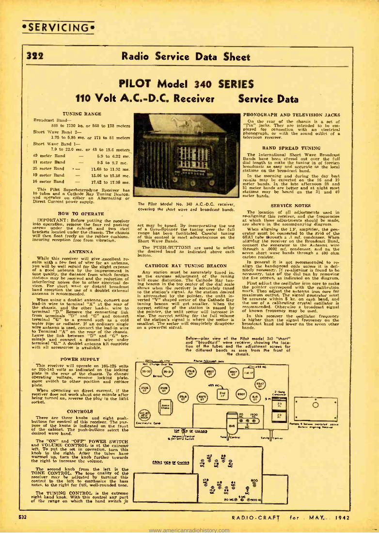
SERVICING
322 Radio Service Data Sheet
PILOT Model 340 SERIES
110 Volt A.C. -D.C. Receiver Service Data TUNING RANGE
Broadcast Band - 636 to 1730 kc. or 560 to 173 meters
Short Wave Band 2- 1.75 to 6.85 mc. or 171 to 61 meters
Short Wave Band 1- 7.0 to 22.0 me. or 43 to 18.6 meters
49 meter Band - 6.9 to 6.22 mc. 31 meter Band - 9.6 to 9.7 mc. 25 meter Band - 11.68 to 11.92 mc. 19 meter Band - 16.06 to 15.88 mc. 16 meter Band - 17.62 to 17.98 mc.
This Pilot Superheterodyne Receiver ha, 10 tubes and a Cathode Ray Tuning Beacon. and operates on either an Alternating or Direct Current power supply.
HOW TO OPERATE IMPORTANT: Before putting the receiver
into operation, remove the four red packing screws under the cabinet and two steel brackets located under the chassis. The chassis will then float freely on the rubber cushions, insuring reception free from vibration.
ANTENNA While this receiver will give .excellent re-
sults with a few feet of wire for an antenna. you will be well repaid for the slight expense of a good antenna by the improvement in tone quality, the distance from which foreign stations may be received and the reduction of interfering noises due to other electrical de- vices. For short wave or distant broadcast band reception the use of a doublet external antenna is recommended.
When using a doublet antenna, connect one lead -in wire to terminal "A" at the rear of the chassis. and the other lead -in wire to terminal "D." Remove the connecting link from terminals "D" and "G" and connect terminal "G" to a ground such as a cold water pipe or radiator. If an ordinary single wire antenna is used, connect the lead -in wire to Terminal "A" on the rear of the chassis. Leave the link between "D" and "G" ter- minals and connect a ground wire under terminal "G." A doublet antenna kit complete with all accessories is available.
POWER SUPPLY This receiver will operate on 106 -125 volts
or 200 -240 volts as indicated on the locking plate in the rear of the chassis. To change operating voltage, remove locking plate. move switch to other position and replace plate.
When operating on direct current, if the receiver does not work about one minute after being turned on, reverse the plug in the light socket.
CONTROLS There are three knobs and eight push-
buttons for control of this receiver. The pur- pose of the knobs is indicated on the front of the cabinet.. The push -buttons select the desired wave band.
The "ON" and "OFF" POWER SWITCH and VOLUME CONTROL is at the extreme left. To put the set in operation, turn this knob to the right. After the tubes have warmed up, turn the knob further towards the right to increase the volume.
The second knob from the left is the TONE CONTROL. The tone quality of the receiver may be adjusted by turning this control to the left to emphasize the bass notes, to the right for full. well -rounded tone.
The TUNING CONTROL is the extreme right hand knob. With this control any part of the range on which the band switch is
The Pilot Model No. 340 A.C.-D.C. receiver, covering the short wave and broadcast bands.
set may be tuned. By incorporating the use of a Gyro-Spinner the tuning over the full range has been facilitated. Careful tuning of this control is most advantageous on the Short Wave Bands.
The PUSH -BUTTONS are used to select the desired band as indicated above each button.
CATHODE RAY TUNING BEACON Any station must be accurately tuned in,
as the careless adjustment of the tuning will cause distortion. The Cathode Ray tun- ing beacon in the top center of the dial scale shows when the receiver is accurately tuned to the station's signal. As the station desired is approached by the pointer, the unlit in- verted "V" shaped sector of the Cathode Ray tuning beacon will get smaller. When the correct setting of the station is passed by the pointer, the unlit sector will increase in size. The correct setting for the full volume of the station's signal is where the sector is smallest. The sector will completely disappear on a powerful signal.
nov ,y,,,v , C..,. -O..r s.
PHONOGRAPH AND TELEVISION JACKS On the rear of the chassis is a set of
"Pin" jacks. They are intended to be em- ployed for connection with an electrical Phonograph. or with the sound outlet of a television receiver.
BAND SPREAD TUNING The International Short Wave Broadcast
Bands have been spread out over the full dial length to make the tuning in of foreign broadcasts as easy and accurate as the local stations on the broadcast band.
In the morning and during the day best results may be expected on the 16 and 19 meter bands. In the late afternoon 26 and 31 meter bands are better and at night most stations may be heard on the 81 and 49 meter bands.
SERVICE NOTES The location of all adjustments used in
re- aligning this receiver, and the frequencies at which these adjustments should be made. are shown in the accompanying diagram.
When aligning the I.F. amplifier, the gen- erator must be connected to the grid of the 6SA7 tube *rough a .1 mf. condenser. When aligning the receiver on the Broadcast Band. connect the generator to the Antenna wire through a .0002 mf. condenser. and on the seven short wave bands through a 400 ohm carbon resistor.
In general it is not recommended to re- align the bandspread coils unless it is defi- nitely necessary. If re- aligning is found to be necessary, take off the dial pan by removing the five screws, as indicated on the diagram.
First adjust the oscillator iron core to make the pointer correspond with the calibration mark. Then adjust the antenna iron core for maximum output. The signal generator must be accurate within 5 kc. on each hand, and the use of a calibrating crystal oscillator is recommended. Otherwise a broadcast signal of known frequency may be used.
In this receiver the oscillator frequency is higher than the signal frequency on the broadcast band and lower on the seven other bands.
Below -plan view of the Pilot model 340 "short" and "broadcast" wave receiver showing the loca- tion of the tubes and the adjustment screws for the different bands as seen from the front of
Me chassis.
1313..,..3 Josh
r
a!f .C1 r'
ahn 12 C7Aila Pce,... O.Or, s_nm
20 iYOo
0 sc
..233/52e., .,
...,.3 s se... ,ti. e.,. , s..,,c .....e
532 RADIO -CRAFT for MAY, 1942
www.americanradiohistory.com

SERVICING
Radio Service Data Sheet 322
V
1.1
o
V
N
Aooa COO
o
floc
011 Of
flOR fl[ floc
<.r w r c wr szl du
V
fIt
mflzz
o[
Jflfl SLI 1
o
w7 J
INDI Of
D
R . V
0
' .
.p Iii,--1
P
+st,- 1 p üü P d P Pe
/ íó
s
RADIO -CRAFT for MAY. 1942 533
www.americanradiohistory.com

SOUND
A Complete P.A. System At Very Low Cost
RICARDO MUNIZ, E.E. *` and ROBERT J. BERGEMANN, JR. **
HIGH fidelity, wide -range tone control, accessibility and portability are here made available to the home con - structor at extremely low cost. In
this modern Address System costly components have been kept at an absolute minimum. The circuit design together with the wide range electronic tone control give fidelity rivaling that found in Broadcast Station amplifiers.
For the constructor wishing a complete system which can be readily carried around from job to job without the need of hauling a multitude of cases and packages this unit is the ideal one. In spite of the great com- pactness it is found that the accessibility of components is greater than that in the more usual designs. The chasses arc mounted in a vertical position on the two sides of the case and these two sides are removable. The sides of the cases are arranged as slid- ing panels which, when removed, expose the "innards" of each chassis. The tubes are easily reached for test or replacement when the back is removed.
The constructor will be pleased to know that drawings for the speaker cabinet will appear in the second part of the article in next issue. The plans given contain the de- tails for the speaker cabinet which is of the bass reflex type, and also the main case, with its chassis and panels.
Since each chassis is a separate unit and Engineer WNYE: Radio Instructor Brooklyn Technical H. S. Graduated June, 1940 from Brooklyn Techni- cal H. S. Fortner President of the Radio Club at B.T.H.S.
534
Above -The complete portable P.A. system with the high -fidelity speaker mounted in the bass re-
flex cabinet. Photo at left shows view of the main chassis array, with ampli- fiers and phono motor. The sec- tional unit construction makes re-
pairs a simple matter.
each panel is also a separate unit, they may be removed individually for changes, im- provements, repairs, etc. This feature is a very important one. Experience has taught us that obsolescence is the bogeyman of the radio trade. Here is a unit that is as nearly obsolescence -proof as it is possi- ble to come.
Heater type tubes have been used throughout so that tNe horizontal place- ment of the tubes will do no harm.
SPEAKER CABINET: This cabinet is adequately pictured in the sketches. It is de- signed so that the black wave reinforces the front ware of the speaker at the lower frequencies, thus improving the bass re- sponse. A Utah 12P speaker was found to give very satisfactory performance. The cabinet should be stained and should be given two coats of shellac and one of var- nish, to preserve the wood and keep it from warping. It is made of 3 ply Y4" fir and is lined with %" celotex. The celotex covers practically all the inside. The details of the joinery will be shown.
"MIKE" CABINET: This cabinet was designed to house a small Utah 3P speaker and Thordarson T -14583 transformer, used as a step up and impedance -matching trans- former. A wide variation in the final ap- pearance is possible with this unit, so as to suit the individual taste, provided one important principle is adhered to: Do not close the back of the cabinet with a piece of wood. Leave the back of the mike cab- inet open. A grill cloth may be used on the back to make it look neat.
Another trick which will improve the
The portable P.A. system here de- scribed can be built from spare parts, where this is neces- sary; the circuit used is so flexible that practically every requirement can be met. The Serviceman as well as the Experimenter will find this uni- versal P.A. system extremely valuable and he should file the data in his hand-
book.
performance of the Utah 3P (used as a mike) is to insert a small piece of soft sponge rubber be- tween the back of the cone and the back frame- work of the speaker unit. This will practically elim- inate "cone resonance." This piece may be ad- justed while listening to
the output of the amplifier off a pair of phones -until quality sounds best. Having found the best position of the piece of rubber it will be found that the electronic control will enable you to make this home- made microphone sound like an expensive dynamic mike.
The unit herein described was built in large measure from parts found in old ra- dios, the junkbox and "bargain counters." Since then these parts are being replaced by standard equivalents, these equivalents are given in the parts list, so that the re- sults attained can be readily duplicated. The constructor may use "junk" tempo- rarily as was done by the authors -and later replace a unit at a time with stand- ard parts.
The record -Player used by the authors was, as can be seen in the photographs, mounted on top of the "CASE." It con- sists of a crystal pick -up and a small self - starting motor having a ten -inch turn- table.
Perhaps the most' outstanding feature of this P.A. system next to the unique hous- ing "CASE" is the electronic tone control. It will give a 15 db. boost or cut off either bass or treble or both at SEPARATE con- trols; there is little interaction between the controls. It will be noted that the tone - control circuit in the pre -amplifier chassis is very simple indeed. Many constructors will want to incorporate this simple elec- tronic tone control in existing P.A. ampli- fiers. It works very well. You will note that a T -14C70 tone control choke is used in the cathode of the 6C5 for bass and a
RADIO -CRAFT for MAY, 1942
www.americanradiohistory.com

SOUND!
MI Rodio Too- CAosra `íñxJ5 l 6H7 RFC / l
.6CO365 / \ ï0,?Ó5
6. f 1 Qj i,
` ¡ C1 óQ, o 4V m A- x /j y x
_ R38 Ss i
C 13 4V Model O.7 As/a/
zro/ "clew
C411 AO MT 25 V
%/R45 7oO M BTi
C/04 R47 / 400V T
111
A 25 MR RTC
f cR %r
400 V
re P.ewp Te.p..,eb a
C.d
R
ToRod.° Jocó
2 250M 8171 a
"._IJ l9 OM
j6p9 87 ;
I R 4
BO/J I NMAti C50 - 4MT
400 V
ÓÉkr7.o/y/,r
//0 V Juryon MoF - A C M tAuv3and
V/d./r Ou/k/s Power Sugdy C/,ass>'s (Fo. PAdpMOb.s. I / ek) g7 O-/MA SOOM' 150oV
V i _ryyyyl osv wA?sov /OM/ OV J P
5MJ sV R rfr,czc Level Aaron, x
r/ E.
84 ii.J
EI,sr
Vrr
Y Y
111
III mosF&
50 M Poled
2 A.rpl F(374.
^
To 500
C/+3 C'/4
Rrc%! s (
6 3 V Cr
83-V J
CR7
16, /0/ M 3
S1
400 V
6C5
'Pre- ARp Cñassis
L°OC o 6SFS
C7 4cov
6.5,17 i
R32
Y Y
zrA641 2 5 V
R5) 3 80, 87 1W /
CL PCIM
- 818 él 50 M
R 35
R20 50 M 871!
IpMf/ 25V
-e SMT R46 400V
art ./
400 V CB C0
C 8 rot-
R64
A
/RC 75000 Cv.+,s CSA./BSá C Shun/
-34 .100V
65J7
ti Tone
Cond.,/
96
Mr9%
Posrr. Amp14c. Chnssm
5IXJM AC CS SlaMwd
a i Mr-
R9/ RCi' CS
lR 54 3 BT 1 w
R50 BW 046
8 MT RT/ 1 HI. 450V 50M-13T7 Ì
8 15 OM 3 O
1141 0 1
37s-
8.275 V
R40
ir If
400 V ! 6LGC FYo/
C27 .25 00V,/
C30 CJ1C32 C33 C34
rr gR 8V ;,, D
.O
sc,,,7 pa.a467 o v
S Wall ,..r..a.doeb.41464 Se/ ol bwved 5.
V P.M 86
F
box rte1 9bf:H9 12SJ7 - R J9
200
Ohms I
oo 45Z5GT 25M7
P,/o/ f 25 V
0
//O V AC -DC
znnf--+ V V W A BC
CH 5
C 2 os-
400 V
SMC9 /2$1-5 /Lo,vCa..,/,vH./ VO/Con/ 1 J
` NO i
5OL6CT R6/
Re Ctg /400V
/ 414
400V
e C
ÁJ7 3M
R 5/ SMeg /W
6
1 C/51
400V
RIO .5A4y 87i
C42 I 10 Mr 2 5 V
4 M/' 400 VJ
'' R25 50 M j
W A
5 MT- 400V)
lRJ6 '- 3000 Ohm6 BTi
""R2J 50 M B7i
11124 50 M eri
C 5/ :op
C52 c.55
711 / `Ti
/6Mf 200V
1122 % 50 M I W
C 48 4 MT
7 400V
r5
T4
L./ V
C43 JOAN 25 V
R55
Óh,f I W
R65
75000 4-'000 ,
A°sñ,/ aC'9ms
ói5fI R 66 C 2
400V 050 V
A.0 DC - /tkan /h* Amp C/osss
I 436 Q,p S/.,°
Diagrams above show the various microphone and phono pickup circuits, as well as the amplifier stages.
etc., used in the complete portable P.A. system designed by Messrs. Munit and Bergemann.
RADIO -CRAFT for MAY, 1942 535
www.americanradiohistory.com
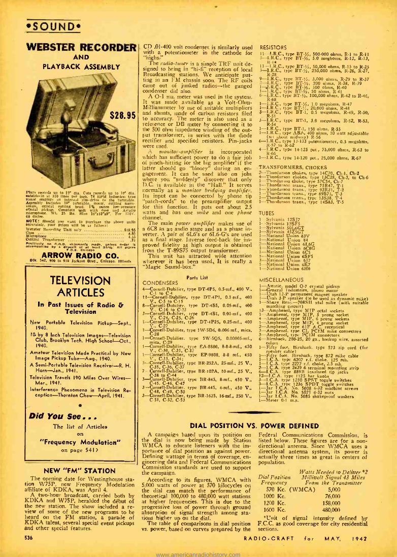
SOUND WEBSTER RECORDER
AND PLAYBACK ASSEMBLY
Plays records up to 1 die. Cuts records up to 10' die. outside -In at 110 lines per Inch. 714 RPM induction type motor employs an internal rim -drive to the turntable. Assembly includes M" turntable motor, cutting mech- anism. crystal cutting head. 1st ounce low -pressure crystal pickup. Complete unit with cane and Asiatic microphone. Wt. 25 lbs. Elise 19":13 "s9 ". For 110V. 60 cycle.. NOTE: Should you want to purchase the above units separately, your prices will be as follows: Webster Recording Unit only $19.95 Case 4.95 Microphone 4.45 Cutting Transformer .75 Positively o C.O.D. shipments ade, unless der is accompanied by a deposit of at least seep. all Price.
F.O.U. Chicago
ARROW RADIO CO. Div. 542, 900 to 910 Jackson Blvd., Chicago. 1111.01$
TELEVISION ARTICLES
In Past Issues of Radio & Television
New Portable Television Pickup -Sept., 1940.
10 by 8 Inch Television Images- Television Club, Brooklyn Tech. High School-Oct., 1940.
Amateur Television Made Practical by New Image Pickup Tube -Aug., 1940.
A Semi -Portable Television Receiver -R. H. Horn -Jan., 1941.
Television Travels 190 Miles Over Wires - Mar., 1941.
Interference Phenomena in Television Re- ception- Thornton Chew - April, 1941.
Did You See... The list of Articles
on
"Frequency Modulation" on page 541 ?
NEW "FM" STATION The opening date for Westinghouse sta-
tion W75P, new Frequency Modulation affiliate of KDKA, was April 4.
A two -hour broadcast, carried both by KDKA and W75P, heralded the début of the new station. The show included a re- view of some of the new programs to be heard on the FM station, a parade of KDKA talent, several special event pickups and other special features.
536
CD .01 -400 volt condenset is similarly used with a potentiometer in the cathode for "highs,"
The radio -tuner is a simple TRF unit de- signed to bring in "hi -fi" reception of local Broadcasting stations. We anticipate put- ting in an FM chassis soon. The RF coils came out of junked radios -the ganged condenser did also.
A O -1 ma. meter was used in the system. It was made available as a Volt -Ohm- Millianuneter by use of suitable multipliers and shunts, trade of carbon resistors filed to accuracy. The meter is also used as a reference or DB meter by connecting it to the 500 ohms impedance winding of the out- put transformer, in series with the diode rectifier and specified resistors. Pin -jacks were used.
.1. monitor- amplifier is incorporated which has sufficient power to do a fair job of pinch- hitting for the big amplifier if the latter should go "blooey" during an en- gagement. It can be used also on jobs where you "suddenly" discover that only D.C. is available in the "Hall." It serves normally as a monitor bridging amplifier. Its input can be connected by phone tip "patch- cords" to the preamplifier output for this function. It puts out about 2.5 watts and has one mike and one phone channel.
The main power amplifier makes use of a 6C8 as an audio stage and as a phase in- verter. A pair of 6L6's or 6L6 -G's are used as a final stage. Inverse feed -back for im- proved fidelity at high output is obtained from the T -89575 output transformer.
This unit has attracted wide attention wherever it has been used.. It is really a "Magic Sound-box."
Parts List CONDENSERS 4- Cornell- Dubilier, type DT -4P5, 0.3 -mf., 400 V.,
C -I to C -4 11.Cornell- Dubilier, type DT-4P1, 0.1mf., 400
V., C -5 to CI5 8- CornellDubilier, type DT -4S5, 0.05 -mf., 400 V., C -16 to C -23 3- Cornell -Duhilier, type DT -4S1, 0.01 -mf., 400 V., C -24.- C -25, C -26
1- .-CornellDubilier, type DT -4P25, 0.25-mf., 400 V., C -27 1- Cornell -Dubilier, type IW-5D6, 0.006mf., mica, C -28 1- Cornell -Dubilier, type 5W-5Q5, 0.00005 -mf., mica, C -29 1- Cornell -Duhilier, type EA -8880, 8.8.8 -mf., 450 V., C -30 C -31, C -32 1- Cornellfiubilier, type EP -9808, 8.8 inf.. 450 V., C -33, C -34; 3- CornellDubilier, type BR -252A, 25 -mf., 25 V., C -35, C -36, C -37
7-Cornell-Dubilier, type BR-102A, 10 -mf., 25 V., C -38 to C-44
3 -Cornell- Dubilier, type BR -845, 8-mf., 450 V., C-45. C -46, C -47 3- Cornell -Dubilier, type BR -445, 4 -mf., 450 V., C-48, C -49, C -50 3- Cornell -Dubilier, type BR -1625, 16 -mf., 250 V., C51, C -52, C -53
RESISTORS 11-- LR.C., type BT -/, 500 -000 ohms, R -1 to R -11 3 -- I.R.C., type BT -/, 5.0 megooms, R -12, R -13,
R -14 11- I.R.C., type BT -/,, 50,000 ohms, R -15 to R -25 3- I.R.C., type BT -y,, 250,000 ohms, R -26, R -27,
R -28 9- I.R.C., type BT -/, 3,000 ohms, R -29 to R -37 2- I.R.C., type BT -/, 200 ohms, R -38, R -39 1-, I.R.C., type BT -/, 500 ohms R -40 1- I.R.C., type BT -/, 50 ohms, k -41 6- I.R.C., type BT -' /a, 100,000 ohms, R -42 to R-46, R -68 1- I.R.C., type BT -/, 1.0 megohms, R -47 1- I.R.C., type BT -;í, 20,000 ohms, R -48 3- I.R.C., type BT -1, 0.5 megohms, R -49, R -50.
. R -51 3- I.R.C., type 11T -1, 3.0 megohms, R -52, R -53, R -54 1- I.R.C., type 11T -1, 150 ohms, R -55 1- I.R.C., type ABA, 400 ohms, 10 watt adjustable (set about midway) R -56 6- 1.R.C., type 13 -133 potentiometer, 0.5 megohms, R -57 to R -62 4- I.R.C., type 14 -125 pot., 75,000 ohms, R -63 to R -66 1- I.R.C., type 14-120 pot., 25,000 ohms, R -67
. TRANSFORMERS, CHOKES 2- Thordarson chokes, type 14C70, Ch -1, Ch -2 4- Thordarson chokes, type 13C28 Ch -3, to Ch-6 1- Thordarson choke, type 57C54, ch -7 1-- Thordarson trans., type 75R47, T -1 1- Thordarson trans., type 92R21, T -2 1 -Thordarson trans., type 89S75, T -3 1- Thordarson trans., type 13S38, T -4 1- Thordarson trans., type 14S83, T -5
TUBES I Sylvania 12S77 I- Sylvania 12SF5 1- Sylvania 50I.6GT 1-Sylvania 45Z5GT 1- National Union 83V 1- National Union 84 2- National Union 6L6G 1- National Union 6C8G 1- National Union 6C5 1- National Union 6SF5 3- National Union 6]]7 1- National Union 6K7 1- National Union 6116
MISCELLANEOUS 1- Astatic. model O.7 crystal pickup 1-- General Industries, phono motor 1 -Utah 12 -P permanent magnet speaker 1 -Utah 3.P speaker (to be used as dynamic mike) 1 -Shure Bros. 708SH xtal mike (with suitable
matching circuit) 13 -Amphenol, type IMP octal sockets 1 -Amphenol, type 111íP, 5 prong socket 4 -Amphenol, type MIP, 6 prong sockets 1-- Amphenol, type MIP, 4 prong socket 2- Amphenol, type 61F A.C. receptical 3- Amphenol, type CL PCIM mike connectors 3- Amphenol, type PCI111 connectors 6- Hirnback, 280 -25, 20 ga., hookup wire, assorted
colors 1-Fifty foot, Birnbaek, type 573 zip cord (for
speaker cable) 1 -Fifty foot. Birnhack, type 872 mike cable I- I.C.A. type 6207 r.f. choke, 125 mh. 1- P.C.A. type 2277 r.f. choke, 2.5 mh. 2- I.C.A. type 2439 6 terminal mounting strip 6- I.C.A. type 889B insulated tip jacks 12- P.C.A. type 1125 bar knobs 3- T.C.A. type 1230 SPST toggle switches 3- T.C.A. type 1236 SPDT toggle switches 1- ar I.C.A. No. 5008 6 -32 machine screws 1- ar I.C.A. No. 5071 6 -32 nuts 1- ar I.C.A. No. 5085 shakeproof washers 1- Peter 0 -1 m.a.
DIAL POSITION VS. POWER DEFINED A campaign based upon its position on
the dial is now being made by Station WMCA to educate listeners with the im- portance of dial position as against power. Defining wattage in terms of coverage, en- gineering data and Federal Communications Commission standards are used to support the campaign.
According to its figures, WMCA with 5,000 watts of power at 570 kilocycles on the dial can match the performance of theoretical 100,000 to 480,000 watt stations at higher frequencies. This is due to the progressive loss of power through ground absorption of signal strength among sta- tions higher up on the dial.
The table of comparisons in dial position vs. power, based on curves prepared by the
Federal Communications Commission, is listed below. These figures are for a non - directional antenna. Since WMCA uses a directional antenna system, its power is actually three times as great in centers of population.
Watts Needed to Deliver *2 Dial Position Millivolt Signal 43 Miles
Frequency From the Transmitter 570 Kc. (WMCA) 5,000
1000 Kc. 76,000 1200 Kc. 158,000 1600 Kc. 480,000
*Unit of signal intensity defined by F.C.C. as good coverage for city residential sections.
RADIO -CRAFT for MAY, 1942
www.americanradiohistory.com
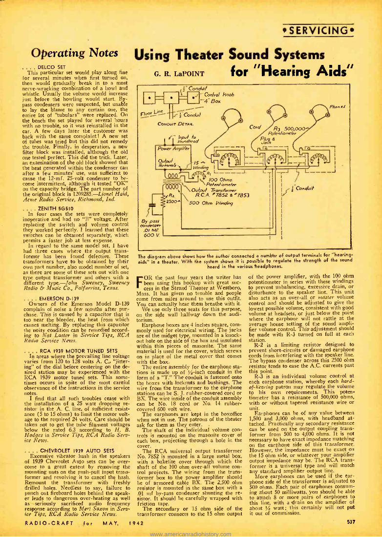
Operating Notes .. . DELCO SET
This particular set would p lay along fine for several minutes when first turned on. then would gradually break in to a most nerve -wracking combination of a howl and whistle. Usually the volume would increase just before the howling would start. By- pass condensers were suspected, but unable to lay the blame to any certain one, the entire lot of "tubulars" were replaced. On the bench the set played for several hours with no trouble, so it was reinstalled in the car. A few days later the customer was back with the same complaint! A new set of tubes was tried but this did not remedy the trouble. Finally, in desperation, a new filter block was installed, although the old one tested perfect. This did the trick. Later, an examination of the old block showed that the heat generated within the condenser can after a few minutes' use, was sufficient to cause the 12 -mf. 25 -volt condenser to be- come intermittent, although it tested "OK" on the capacity bridge. The part number of the original block is 1209285.- Lionel Haid, Acme Radio Service, Richmond, Ind.
. . ZENITH 56510 In four cases the sets were completely
inoperative and had no "B" voltage. After replacing the switch and volume control they worked perfectly. I learned that these switches can be obtained separately, which permits a faster job at less expense.
In regard to the same model set, I have had three cases where the output trans- former has been found defective. These transformers have to be obtained by their own part number, also model number of set, as there are some of these sets out with one type output transformer and others with a different type.-John Sweeney, Sweeney Radio & Music Co., Falfurrias, Texas.
.. EMERSON D -139 Owners of the Emerson Model D -139
complain of noise a few months after pur- chase. This is caused by a capacitor that is too near the bleeder, the heat from which causes melting. By replacing this capacitor the noisy condition can be remedied accord- ing to Nat Laster in Service Tips, RCA Radio Service News.
.. RCA 1939 MOTOR TUNED SETS In areas where the prevailing line voltage
varies from 120 to 128 volts A. C,, "jitter - ing" of the dial before centering on the de- sired station may be experienced with the RCA 1939 motor tuned sets. This some- times occurs in spite of the most careful observance of the instructions in the service notes.
I find that all such troubles cease with the installation of a 25 watt dropping re- sistor in the A. C. line, of sufficient resist- ance (5 to 15 ohms) to limit the motor volt- age to the required 24 volts. Care should be taken not to get the tube filament voltages below the rated 6.3 according to H. B. Hodges in Service Tips, RCA Radio Serv- ice News.
.. CHEVROLET 1939 AUTO SETS Excessive vibrator hash in the speakers
of 1939 Chevrolet Aglo sets can be over- come to a great extent by removing the mounting nuts on the push -pull input trans- former and revolving it to cancel the hash. Remount the transformer with freshly drilled holes. Needless to say, failure to punch out fireboard holes behind the speak- er leads to dangerous over -heating as well as seriously sacrificed audio frequency response according to Merl Saxon in Serv- ice Tips, RCA Radio Service News.
RADIO -CRAFT for
SERVICING
Using Theater Sound Systems G. R. LaPOINT for "Hearing Aids"
3" Conduit Conked knob 4" Box 111-U_11
Fioor Li2!"-- I Coiwi117
CONDUIT QETAe. Cord R3 500,000
Polenhomekr Plug &
Phonss
/5 Winoóny I
Re L - - - -J 100 Ohms.
Po/tnhi me /er Oulpu/ Transformer
R.C.A. "7852 &'7853 500 Ohm Winding
By pos. Condenser
.0I Mf 600 V
y Re 2500
X Conduit
The diagram above shows how the author connected a number of output terminals for "hearing - aids" in a theater. With the system shown it is possible to regulate the strength of the sound
heard in the various headphones.
FOR the past four years the writer has been using this hookup with great suc- cess in the Strand Theater at Westboro,
Mass. It has given no trouble and people come from miles around to use this outfit. You can actually hear them breathe with it.
We use only three seats for this purpose, on the side wall halfway down the audi- torium.
Earphone boxes are 4 inches square, com- monly used for electrical wiring. The jacks are of the midget type, mounted in a knock- out hole on the side of the box and insulated within thin pieces of masonite. The same material is used for the cover, which screws on in place of the metal cover that comes with the box.
The entire assembly for the earphone sta- tions is made up of % -inch conduit in the form of a "T." The conduit is fastened onto the boxes with locknuts and bushings. The wire from the transformer to the earphone stations can be S. J. rubber -covered cord or BX. The wire inside of the conduit assembly can be No. 18 cord or No. 14 rubber - covered 600 volt wire.
The earphones are kept in the boxoffice when not in use. The patrons of the theater ask for them as they enter. .
The shaft of the individual volume con- trols is mounted on the masonite cover of each box, projecting through a hole in the cover.
The RCA universal output transformer No. 7852 is mounted in a large metal box, with a bakelite cover through which the shaft of the 100 ohm over -all volume con- trol projects. The wiring from the trans- former box to the power amplifier should be of armored cable BX. The 2,500 ohm resistor is mounted in the same box with a .01 mf by -pass condenser shunting the re- sistor. It should be carefully wrapped with friction tape.
The secondary or 15 ohm side of the transformer connects to the 15 ohm output
MAY, 1942
of the power amplifier, with the 100 ohm potentiometer in series with these windings to prevent unbalancing, excessive drain, or disturbance to the speaker line. This unit also acts as an over -all or master volume control and should be adjusted to give the lowest possible volume, consistent with good volume at headsets, or just below the point where the earphone will not rattle at the average house setting of the sound ampli- fier volume control. This adjustment should be made with R -3 turned on full at each station.
R -2 is a limiting resistor designed to prevent short- circuits or damaged earphone cords from interfering with the speaker line. The bypass condenser across this 2500 ohm resistor tends to ease the A.C. currents past this point.
R -3 is an individual volume control at each earphone station, whereby each hard - of- hearing patron may regulate the volume to his own requirements. This poten- tiometer has a resistance of 500,000 ohms, with or without tapered resistance wire or unit.
Earphones can be of any value between 1,500 and 3,000 ohms, with headband at- tached. Practically any secondary resistance can be used on the output coupling trans- former from 500 to 4,000 ohms. It is not necessary to have exact impedance matching on the earphone side of this transformer. However, the impedance must be exact on the 15 ohm side, or whatever your amplifier output impedance may be. The RCA trans- former is a universal type and will match any standard amplifier output line.
More earphones can be used if the ear- phone side of the transformer is adjusted to 500 ohms. Each pair of earphones consum- ing about 50 milliwatts, you should be able to attach 8 or more pairs of earphones to this line, with a drain on the amplifier of about IA watt; this certainly will not put it out of commission.
537
www.americanradiohistory.com

SOUND
Two different models of the Sound Recorder; the voice is recorded on unbreakable paper discs.
PAPER -DISC SOUND RECORDER The Memovox is a newly developed "sound- recording" apparatus suitable for use in office or board room, etc. Long recordings may be made on paper discs at slight cost. These discs may be played back as many times as re-
quired, and they may also be mailed for transcription by the recipient.
THE accompanying photos and diagrams show one of the latest developments in sound recording for use in offices, board meetings, etc., and known as the
Memovox. Through a microphone (placed in any convenient location in a room) the apparatus records voice or music. The re- cordings are made on a durable light plas- tic disc, ideal for air mailing or compact filing. Each side of the disc records one full hour without interruption (or may be stopped and started at will). When one hour of recording on the disc is completed, the disc is simply turned over and record- ing begins on the reverse side. The cost of one hour of recording is only a frac- tional part of a dollar. There is absolutely no processing -one can record and repro- duce simultaneously! By utilizing a set- back mechanism, one can play -back what was being recorded several minutes earlier, while the device is still continuously re- cording-or one may listen to the full hour when the recording has been completed.
For transcribing purposes the operator using the system can employ either ear- phones or loudspeaker, whichever she wishes. The transcriber presses the run foot pedal, listens to as many words as she thinks she can retain and then lifts her foot. As soon as the foot is lifted and the contact broken, the turntable becomes sta- tionary at the point of the last word she heard. When she presses the run pedal again, she immediately picks up the dext word. If the transcriber desires to set back and repeat what she heard or typed, she places her foot on the setback pedal. The turntable then runs in the reverse
638
direction until it has traversed the neces- sary distance to repeat the desired words. To proceed, as before, she merely presses the run pedal.
Whether the recorded voice discs are to be reproduced in group meetings, in homes, or private offices, this instrument is as simple to operate as any radio set. The volume can be turned up or down without loss of any clear tone reception.
It is not necessary to run through the entire record to find a specific part. The operator simply sets the reproducer head to the point where the subject is indicated on the log card, and will repeat only that portion of the record desired. Through the simple pedal mechanism, in operation any part of the disc may be repeated as many times as necessary.
Over 120 hours of continuous recording may be stored in one inch of filing space. Either side of every disc is capable of re- cording over a full hour's material, and 60 of these discs may be stored away com- fortably in a single inch of filing space. The discs are tough, flexible, and almost indestructible under any reasonable usage, the manufacturers claim. There are no threads or shavings with this machine. The discs used to record the speech are non- inflammable and safe to handle. The discs will not break if they are dropped and may be mailed anywhere. The discs may be played back at any time and also through many reproductions, with no ap- preciable change in the high fidelity re- production. The discs are impervious to ordinary changes in temperature and hu- midity and are not affected by weather.
The photographs show large and small models of the special recording apparatus here described and the loud speaker is built into the apparatus. A headphone jack is provided with a foot control pedal and also a microphone jack. A feature of this apparatus is that it is not necessary to talk close to the microphone. It may be placed in any convenient location in the room.
The automatic repeat mechanism makes it simple for any stenographer to transcribe the recorded voice with
FUNCTIONAL CHART OF MODEL AA CONTINUOUS RECORDER
1. Recording Level Indicator: Shows the re- cording level amplitude in arbitrary markings on an easy -to-read minimum and maximum scale.
2. Master Switch: This switch controls the pow- er supply to the entire instrument.
3. Microphone Jack: Permits the conn,etion of a high impedance microphone to the record- ing system.
4. Microphone Gain Control: Regulates the sound level from either a local microphone or a high impedance input.
5. Input Channel Gam Controls: These are mix- ers from three 20.000 -ohm bridging circuits, which allow any one of three signals of dif- ferent intensities to be equalized and re- corded.
6. Log Card: This card is inserted on the log card deck, and indicates the elapsed recording time. Space is provided on the card for no- tations by the operator. Card is then filed with the record and remains available for accurate reference when needed.
7. Log Card Clamp: Holds the log card in place.
8. Log Indicator: Follows along the log card as the recording head moves across the rec- ord, and is used in indexing the record.
9. Carriage Safety Stop: Used to lock the re- corder head into a fixed position when machine
RADIO -CRAFT for MAY, 1942
www.americanradiohistory.com
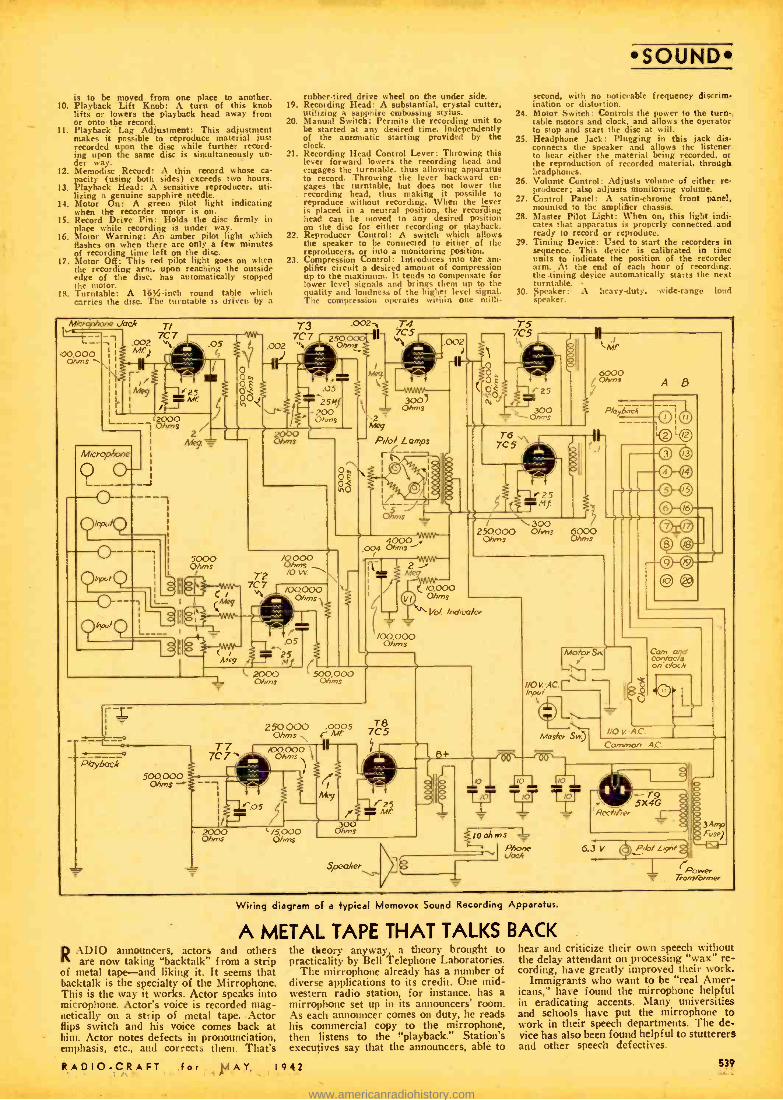
is to be moved from one place to another. 10. Playback Lift Knob: A turn of this knob
lifts or lowers the playback head away from or onto the record.
11. Playback Lag Adjustment: This adjustment makes it possible to reproduce material just recorded upon the disc while further record- ing upon the same disc is simultaneously un- der way.
12. Memodisc Record: A thin record whose ca. pacity (using both sides) exceeds two hours.
13. Playback Head: A sensitive reproducer. uti- lizing a genuine sapphire needle.
14. Motor On: A green pilot light indicating when the recorder motor is on.
15. Record Drive Pin: Holds the disc firmly in place while recording is under way.
16. Motor Warning: An amber pilot light which flashes on when there are only a few minutes of recording time left on the disc.
17. Motor Off: This red pilot light goes on when the recording arm, upon reaching the outside edge of the disc, has automatically stopped the motor.
lg. Turntable: A 16% -inch round table which carries the disc. The turntable is driven by a
rubber -tired drive wheel on the under side. 19. Recording Head: A substantial, crystal cutter,
utilizing a sapphire embossing stylus. 20. Manual Switch: Permits the recording unit to
be started at any desired time, independently of the automatic starting provided by the clock.
21. Recording Head Control Lever: Throwing this lever forward lowers the recording head and engages the turntable, thus allowing apparatus to record. Throwing the lever backward en- gages the turntable, but does not lower the
. recording head, thus making it possible to reproduce without recording. When the lever is placed in a neutral position, the recording head can be moved to any desired position on the disc for either recording or playback.
22. Reproducer Control: A switch which allows the speaker to be connected to either of the reproducers, or into a monitoring position.
23. Compression Control: Introduces into the am- plifier circuit a desired amount of compression up to the maximum. It tends to coni pensate for lower level signals and brings them up to the quality and loudness of the higher level .ig nab. The compression operates within one milli-
SOUND second, with no noticeable frequency discrim- ination or distortion.
24. Motor Switch: Controls the power to the turn- table motors and clock, and allows the operator to stop and start the disc at will.
25. Headphone Jack: Plugging in this jack dis- connects the speaker and allows the listener to hear either the material being recorded, or the reproduction of recorded material, through headphones.
26. Volume Control: Adjusts volume of either re- producer; also adjusts monitoring volume.
27. Control Panel: A satin -chrome front panel, mounted to the amplifier chassis.
28. Master Pilot Light: When on, this light indi- cates that apparatus is properly connected and ready to record or reproduce.
29. Timing Device: Used to start the recorders in sequence. This device is calibrated in time units to indicate the position of the recorder arm. At the end of each hour of recording, the -timing device automatically starts the next turntable.
30. Speaker: A heavy -duty, -wide -range loud speaker.
i00 000 Ohms
'Jack T/
-, I
.002 77
M T3
7C7 .002 y
1
.002- CS
.002 J
L
4/4
2000 s
2 Meg.
.05 251
Ohms
..E' t
t
4`/4o Ó
2000 Ohms
O *- /0000 O/0
vv.
j004 Ohms 4000 -'
il.
III
_.05 #
Meg 1- fl-S pt L 2000
Ohms (500,000
Ohms
2 Meg
C A7.000 Ohms
\``.. fra/. /nd,co/ae
/00.000 Ohms
r- I
-0
P.(ryóac.4 500.000
Ohms
T7 250000 0M005 7C5 Qhms
L
Speaker
a ;O
tt
Motor$w.) ! .-11
110 V. AC .I lnp.l
Mask, S )
0
Cam ana conlocls on clock
01/ AC Common AC
t0 l° y TIT TKT
1.
/oohms Phone- 6.3 V
Wiring diagram of a Typical Memovox Sound Recording Apparatus.
A METAL TAPE THAT TALKS BACK RA1)l0 announcers, actors and others
are now taking "backtalk" from a strip of metal tape -and liking it. It seems that backtalk is the specialty of the Mirrophone. This is the way it works. Actor speaks into microphone. Actor's voice is recorded mag- netically on a strip of metal tape. Actor Hips switch and his voice comes back at him. Actor notes defects in pronounciation, emphasis, etc., and corrects them. That's
RADIO -CRAFT for MAY, I
the theory anyway, a theory brought to practicality by Bell Telephone Laboratories.
The mirrophone already has a number of diverse applications to its credit. One mid- western radio station, for instance, has a microphone set up in its announcer; room. As each announcer comes on duty, he reads his commercial copy to the mirrophone, then listens to the "playback." Station's executives say that the announcers, able to
942
hear and criticize their own speech without the delay attendant on processing "wax" re- cording, have greatly improved their work.
Immigrants who want to be "real Amer- icans," have found the mirrophone helpful in eradicating accents. Malty universities and schools have put the mirrophone to work in their speech departments. The de- vice has also been found helpful to stutterers and other speech defectives.
539
www.americanradiohistory.com
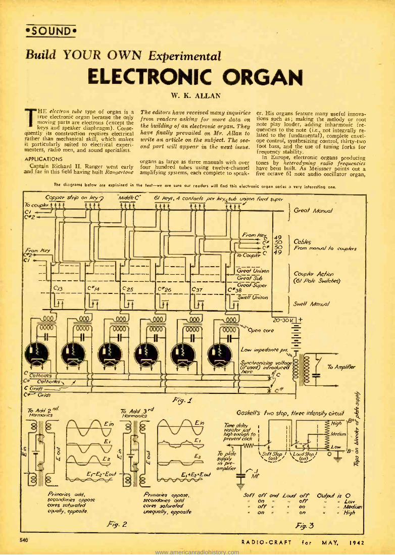
SOUND
Build YOUR OWN Experimental
ELECTRONIC ORGAN
THE
electron tube type of organ is a truc electronic organ because the only moving parts are electrons (except the keys and speaker diaphragm). Conse-
quently its construction requires electrical rather than mechanical skill, which makes it particularly suited to electrical experi- menters, radio men, and sound specialists.
APPLICATIONS Captain Richard H. Ranger went early
and far in this field having built Rangcrtone
W. K. ALLAN
The editors have received many inquiries from readers asking for more data on the building of an electronic organ, They have finally prevailed on Mr. Allan to write an article on the subject. The sec- ond part will appear in the next issue.
organs as large as three manuals with over four hundred tubes using twelve- channel amplifying systems, each complete to speak-
er. His organs feature many useful innova- tions such as; making the melody or root note play louder, adding inharmonic fre- quencies to the note (i.e., not integrally re- lated to the fundamental), complete envel- ope control, synthesizing control, thirty -two foot bass, and the use of tuning forks for frequency stability.
In Europe, electronic organs producing tones by heterodyning radio frequencies have been built. As Meissner points out a five octave 61 note audio oscillator organ,
The diagrams below are explained in the test -we are sure our readers will find this electronic organ series a very Interesting one.
Copper sfr? on key 2 76c r
CI Cß'2 i
Middle C 6/ keys, 4 con/acfs per key, sub unsan feed super f f ft"
From Ney. e M r 00
76 Comma` C
Gres/ Unison
Greo1 Sub Greñ/ Super
C*38 we // Unison
ToApN2/gI Harmonics
Primaries odd, secondaries oppose cores saturated equally, opposite.
To Add 3rd Harmonics
W
Fig. 2
Primaries oppose. seconcóries add cores saturated unequv /y, opposite
1 Great Manua/
49 .50
I
CQ6/es 50 From manual to capers 49
Cocpkr Ac/'.an (6/ Pa/e Switches)
Swe// Monty/
20-30 t! _L+
Open core
Low impedance pri. T
Synchronii g to /huge
here caused) introduced
C
* C#
To Amplifier
Gasket /s two slop, three intensity circui/
Time aiky I
resaforjust high enough io I
preven / chck I
,Topla pre-
amplifier y.,.1
High +s6
tiled
Low "Son Slop / \LoudS/opI O \(on) / (on) /
S Mf
Soft off and Loud off on . off off on On - On
F.y: 3
B
O211put is O Low Medrán
- High
540 RADIO -CRAFT for MAY, 1942
www.americanradiohistory.com
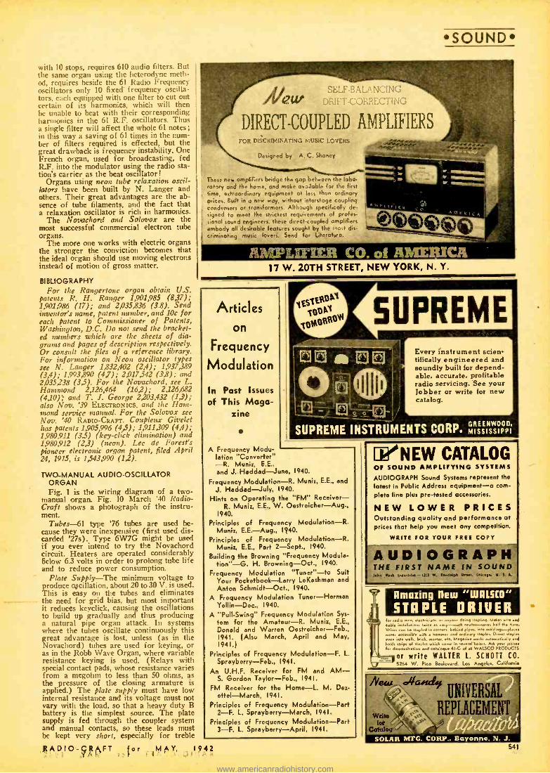
with 10 stops, requires 610 audio filters. But the same organ using the heterodyne meth- od, requires beside the 61 Radio Frequency oscillators only 10 fixed frequency oscilla- tors, each equipped with one filter to cut out certain of its harmonics, which will then he unable to beat with their corresponding harmonics in the 61 R.F. oscillators. Thus a single filter will affect the whole 61 notes; in this way a saving of 61 times in the num- ber of filters required is effected, but the great drawback is frequency instability. One French organ, used for broadcasting, fed RF. into the modulator using the radio sta- tion's carrier as the beat oscillator!
Organs using neon tube relaxation oscil- lators have been built by N. Langer and others. Their great advantages are the ab- sence of tube filaments, and the fact that a relaxation oscillator is rich in harmonics.
The Novachord and Solovox are the most successful commercial electron tube organs.
The more one works with electric organs the stronger the conviction becomes that the ideal organ should use moving electrons instead of motion of gross matter.
BIBLIOGRAPHY For the Rangertone organ obtain U.S.
patents R. H. Ranger 1,901,985 (8,37); 1,901,986 (17); and 2,035,836 (3.8). Send inventor's name, patent number, and 10c for each patent to Commissioner of Patents, Washington, D.C. Do not send the bracket- ed numbers which are the sheets of dia- grams and pages of description respectively. Or consult the files of a reference library. For information on Neon oscillator types see N. Langer 1,832,402 (2,4); 1,937,389 (3,4); 1,993,890 (47); 2,017,542 (3,8); and 2,035,238 (3,5). For the Novachord, see L. Hammond 2,126,464 (16 ,2); 2,126,682 (4,10); and T. 1. George 2 ,203,432 (1,ï'); also Nov. '39 ELECTRONICS, and the Ham- mond service manual. For the Solovox see Nov. '40 RADIO- CRAFT. Conpleux Givelet has patents 1,905,996 (4,5); 1,911,309 (4,4); 1,980,911 (3.5) (key -click elimination) and 1,980,912 (2,3) (neon). Lee de Forest's pioneer electronic organ patent, filed April 24, 1915, is 1,543,990 (1,2).
TWO- MANUAL AUDIO -OSCILLATOR ORGAN Fig. 1 is the wiring diagram of a two -
manual organ. Fig. 10 March '40 Radio - Craft shows a photograph of the instru- ment.
Tubes -61 type '76 tubes are used be- cause they were inexpensive (first used dis- carded '27s). Type 6W7G might be used if you ever intend to try the Novachord circuit. Heaters are operated considerably below 6.3 volts in order to prolong tube life and to reduce power consumption.
Plate Supply-The minimum voltage to produce o,scillation, about 20 to 30 V. is used. This is easy on the tubes and eliminates the need for grid bias, but most important it reduces keyclick, causing the oscillations to build up gradually and thus producing a natural pipe organ attack. In systems where the tubes oscillate continuously this great advantage is lost, unless (as in the Novachord) tubes are used for keying, or as in the Robb Wave Organ, where variable resistance keying is used. (Relays with special contact pads, whose resistance varies from a megohm to less than 50 ohms, as the pressure of the closing armature is applied.) The plate supply must have low internal resistance and its voltage must not vary with the load, so that a heavy duty B battery is the simplest source. The plate supply is fed through the coupler system and manual contacts, so these leads must be kept very short, especially for treble
RADIO -CRAFT for 1MAY, 1942
SOUND
. (Jew
DIRECT- COUPLED AMPLIFIERS
'.ELF-BAL AiVCifdc, i[..i..
Eon DISCRIMINATING MUSIC LOVERS
{
Designed by A. C. Shoney
These new amplifiers bridge the gap between the lobo. rotary and the home, and make avoilable for the first time, extraordinary equipment at less than ordinary prices. Built in a new way, without lnterstage coupling condensers or transformers. Although specifically de- signed to meet the strictest requirements of profes- sional sound engineers. these direct-coupled amplifiers embody all desirable features sought by the hoe d s.
criminating music lovers. Send for Literata':.
A41'LlrltR L\Ih.RII
A
7,IEIarIER CO. of AMERICA 17 W. 20TH STREET, NEW YORK, N. Y.
Articles on
Frequency
Modulation
In Past Issues of This Maga-
zine
Every Instrument scien- tifically engineered and soundly built for depend- able, accurate, profitable radio servicing. See your Jobber or write for new catalog.
SUPREME INSTRUMENTS CORP. MISSISSIPPI
A Frequency Modu- lation "Converter" -R. Munit, E.E., and J. Haddad -June, 1940.
Frequency Modulation -R. Muni:. E.E., and J. Haddad -July, 1940.
Hints on Operating the "FM" Receiver - R. Munit, E.E., W. Oestreicher -Aug.,
1940.
Principles of Frequency Modulation -R. Muni; E.E. -Aug., 1940.
Principles of Frequency Modulation -R. Munir, E.E., Part 2- Sept., 1940.
Building the Browning "Frequency Module - tion"-G. H. Browning -Oct., 1940.
Frequency Modulation "Tuner " -to Suit Your Pocketbook -Larry LeKashman and Anton Schmidt -Oct., 1940.
A Frequency Modulation Tuner- Herman Yellin -Dec., 1940.
A "Pull- Swing" Frequency Modulation Sys- tem for the Amateur -R. Muni:, E.E.,
Donald and Warren Oestreicher -Feb., 1941. (Also March, April and May, 1941.)
Principles of Frequency Modulation -F. L. Sprayberry -Feb., 1941.
An U.H.F. Receiver for FM and AM- S. Gordon Taylor -Feb., 1941.
FM Receiver for the Home -L. M. De:- ettel- March, 1941.
Principles of Frequency Modulation -Part 2 -F. L. Sprayberry- March, 1941.
Principles of Frequency Modulation -Part 3 -F. L. Sprayberry -April, 1941.
1'NEW CATALOG OF SOUND AMPLIFYING SYSTEMS
AUDIOGRAPH Sound Systems represent the latest in Public Address equipment -a com-
plete line plus pre -tested accessories.
NEW LOWER PRICES Outstanding quality and performance at prices that help you meet any competition.
WRITE FOR YOUR FREE COPY
AUDIOGRAPH THE FIRST NAME iN SOUND Ulm utr 1Pdemle4 -1.1.17 w. oedetpb Strew, Ornse, U. f..
Amazing new "W111.510"
STAPLE DRIVER Ior radio n,eb electrician. or 'wane doing ,rapbng. Makes -ire and
cable rnOaliations ha. a -.ouch neater-say., k.11 r n
w,. n be stapled at co y. beh,nd pipes o .naldngsl -.plat accessible with I,.n,ner and ordinary staple.. Dives ...plat
even into .ell,, bricl, mortar. c. Magazine or I. ,cally .4 holds strips of staples .filch cane .n ..naval colors.
auto Ask your jobber
lot 4em660..66n end cah.legue U.0 of oil WALSCO PRODUCTS
or write WALTER L. SCHOTT CO. 5264 W. Pico F- Los Ant,.. .. Californie
JV "dia4s `j UNIVERSAL
wri REPLACEME
541
e
www.americanradiohistory.com

Çó réPourses
SOUND New Direct - Coupled FM - AM
AMPLIFIER MANUAL By A. C. SHANEY
Chief Engineer, :1 mptiRrr Co. .: Americo
For the Layman, Serviceman Recordist and Engineer
Regardleas of whether you are interested In the final. type of phonograph reproduction, high fidelity recording. round -ofilm applications. FM or AM programs. you will find invaluable information in (hie practical handbook.
Written by the leading exponent of direct-coupled am- plifiers who has spent more than 10 years improving and perfecting the famous Loftin-White circuit. Explains the theory and peer eked application of: Variable Speed Non -Overloading Push -Pull Expansion
Non - Frequency D iswlminating Scratch Suppression Push -Pull Balanced Direct- Coupled Amplification
. Push -Pull High -Frequency Equalization PushPull Low- Frequency Equalization
Push -Pull Volume Compression Automatic Volume Limitation
Automatic Volume Control Calibrated V.U. Indicator Audio Spectrum Control
Remote Control If you are interested in the latest audio developments. You
authentic oartl to lee. onwithout Dlrert1'Coucomplete l
Dc compilation 32
8t4 a 11'. Over 100 diagram. and illustration.. Pelted to Cover Cost of Z Printing and Mailing
If Send Stamps Or Coin
AMPLIFIER CO. of AMERICA 17 WEST 20TH STREET, NEW YORK. N. Y.
e . NIBN EFFICIENCY
Sound Notional Defense
that i NATIONAL
why DE-
FENSE SOUND SYSTEMS
am equipped With University Reflex
HIGH POWER LOUDSPEAKERS
UNIVERSITY UNS. in MIME ST. N.Y.C.
Inventions Wanted Pdtented or Unpdtented We have been successfully selling Invention,. patented and unpatented, since 1924. Write us, if a practical- useful idea for sale.
CHARTERED INSTITUTE of AMERICAN INVENTORS
Dept. 109 Barrister Building. Washington. D.C.
PATENTS - TRADE MARKS Booklet concerning Inventions & Patents
Form "Evidence of Conception" with instructions for use and "Schedule of Government and Attorneys Fees" -Free
LANCASTER. ALLWINE & ROMMEL Registered Patent Attorneys
416 Bowen Bldg. Washington, D. C.
COMPLETE NOME STUDY COURSES educational books, Slightly weed. Sold.
subject Money All guarantee. ash paid for
tused urse*. Full de- ail, and Illustrated 70- Page bargain catalog FREE. Write today!
. 500 Sherman. Dept. E -210. Chicano
542
notes, in order that changes in length in the plate circuit e.g., via sub or super coupler, will not affect oscillator pitch. For this rea- son a Wick's Action or Casavant Roller Action manual in which the couplers are part of the keyboard would be much superior to the cable type. Used manuals may often be obtained from organ builders advertising in organ magazines. (A sample copy of The Diapason is 15c from "The Diapason," 1511 Kimball Building, 306 South Wabash Are., Chicago, 111.)
Coils -For the lowest octaves audio transformers are used, with various frac- tions of the laminations omitted, and the remainder restacked to leave a large air gap, because open cores show less varia- tion in frequency with changing tubes and battery, since the plate current can't saturate the core. The coils are grouped so that magnetic leakage will occur between all C's, all C #'s, etc., to aid in keeping the octaves perfectly in tune. All the tubes of one note (e.g., C's) are placed next to those a fifth away, e.g. G's, all G's near D's, etc. This, because a fifth is the great- est harmony after an octave. The capacity on the bottom CI is .15 mf. and on the top C61 about ..0005 mf. Dual- winding tele- phone line- switch coils were used for the higher octaves but doubtless audio trans- formers would do. Interchanging coils, tubes, and condensers will come very close to the note; if you cannot get it, .001 mf. condensers serve as trimmers around C25 and compression type mica trimmer con- densers can be used on the top octave. It is essential that the primary of the output transformer have a very low impedance, and its core an air gap, to prevent change in pitch when additional notes are played. An extra heavy audio transformer with a one square inch Cbre and approximately 150 turns of #24 in place of the primary is used. A car ignition coil will work. If the primary has appreciable impedance compared to the oscillator's output, the signal output will drop as more notes are played, due to the shunting action of oscil- lators.
TUNING The oscillators are tuned by (1) varying
the number of laminations, (2) sliding a lamination in or out, (3) moving coil along the core, which is the central piece of the "E ", (4) varying the air gap, (5) varying The capacity (trimmer condensers are used on the top octaves). Changing the plate voltage will upset the tuning, so deter- mine it before starting to tune. Keeping the cathode leads and grid returns of all C's, all C #'s, etc., in groups, helps to keep the octaves in tune. It has hitherto seemed impossible to build an instrument which would play true diatonic scales in all keys, so equal tempering is used as a compromise. However, the tendency of vacuum tube oscillators to ''pull in" to a frequency harmonically related, makes it possible for a tube to be a diatonic C# in one chord and a diatonic Db in another. This may account for the beautiful tone of this in- strument.
TONE QUALITY Tubes having no bias produce a beautiful
"string" tone, but a small suggestion of keyclick is present. Capacity connected across the output transformer changes this to "diapason" tone, with no keyclick, and still more capacity produces a clear "flute" tone, which is so free of harmonics that it sounds much better with an octave coupler (i.e., IOOD /o second harmonics. 2mf. across the primary of the audio transformer de- scribed above, or .15 mf. across the second- ary of an ignition coil will do). Changing
the amount of air gap in the output trans- former alters the tone quality. New tonal effects can be produced by saturating the cones of two amplifier transformers con- nected in series, Fig. 2. Primaries aiding, secondaries opposing, cores saturated equal- ly, adds a second harmonic; primaries opposing, secondaries aiding, core legs saturated unequally, adds a third harmonic. Also full -wave rectification, followed by passage through a transformer, changes the tone; a pentode with wrong values of volt- age on its grid produces striking effects. In these cases, while a single note sounds fine, when other notes are added to form a chord the non -linearity of the system pro- duces cross -modulation tones, which create unbearable harshness, so these tones must be limited to a single note at one time (e.g., by a melody coupler, or use of a separate channel for each note, like the Rangertone.)
COUPLERS Some type of coupler is necessary in
order to make one manual (Melody or Great) sound louder than the other manual (Accompaniment or Swell). Sub, unison, super and two octave higher couplers, as well as the twelfth and seventeenth require seven contacts per key including the feed (see Fig. 1). If you desire unified fake stop names they could be called Bourdon 16', Diapason 8', Flute 4', Piccolo 2', Nazard 2 2/3' and Tierce 1 3/5' with the connections such that when middle C25 is played C13, C25, C37, C49, G44 and E53 as the case may be, sound. They pro- duce the sub fundamental, fundamental, second harmonic, fourth harmonic, third harmonic, and fifth harmonic respectively.
When used in conjunction with other types of stops e.g., reed, electrostatic, elec- tromagnetic, or photoelectric, it is an ad- vantage to have the electron tube oscillator tones available in two or three different intensities. Three intensities may be ob- tained from two stops when wired by F. Gaskell's system, using a S.P.D.T. switch on the soft stop and a D.P.D.T. switch on the loud stop, see Fig. 3. This makes it louder to add a soft stop when the loud stop is on, a thing not true of some commercial electric organs.
Systems for Controlling Pitches -The Novachord uses iron core high Q oscilla- tor coils for the top octave, and subdivides their frequencies for the lower octaves. Rangertone stabilizes the bass with tuning forks and doubles their frequencies for octaves.
Instead of 48 tubes for 4 octaves, 12 would do if they were dual triodes (6A6, 6N7, 6C8 or 6F8) and George's double con- tacts were used. This depends on the prin- ciple that two adjacent notes are rarely required simultaneously, so for C the tube is rendered operative while for C# it is rendered operative and the frequency changed by the additional contact. (See Patent 2,203,432.)
The results obtained from tube oscilla- tors can be duplicated by other sources, e.g rotating tone generators, and much more striking effects can be obtained from the tubes used as keying controls. For this reason the writer no longer uses tubes as oscillators, but has converted them to key- ing controls and highly recommends them for this purpoe.
Part II- Conclusion in Next Issue.
Electronic Organ Let's Hear from YOU -Electronic Organ
FANS! The Editors are anxious to receive articles
on simple vacuum tube organs, as well as the more complex.
RADIO -CRAFT for MAY.. 1942
www.americanradiohistory.com

{ Akut "Type o S¢tvie¢ A't'cznual/
RADIO CIRCUIT MANUAL -1941 The Only EDITED Manual
Ever Published !
DIRECTORY OF RECEIVERS MANUFAC- TURED IN 1940 AND UP TO JUNE, 1941
MORE INFORMATION IN HALF THE NUMBER OF PAGES
The value of a service manual le measured not by the number of pages
but by the amount of useful information. Thus. in only 736 pages this Radio Circuit Manual covers over 200 receiver mode's MORE than does
any other competitive manual In twice the number of pages. HOW DID WE DO IT? . ,
By Increasiop the size of our page; by discarding non- essentlal
data and editing the balance: by listing only those receivers which the
Service Engineer will definitely have to repair (no oommunicatlons er
export receivers, no shortwave sets or amplifiers, no electronic devices.
etc.): by many months of hard work based on a definite plan of procedure
end a clear understanding of the actual requirements of the Service Engi- neer. There is no "dead weight" information to add bulk to this Manual. Every word counts. Every minute of reading time is well spent.
THE OLD TYPE MANUALS -Bulky. 4.-. heavy. hard to handle. space consum-
ing. less USEFUL data despite greater number of palm.
OUR NEW MANUAL -Lighter. com- pact, easy to handle. takes half as much room on the shelf- more USEFUL information despite fewer number of 1 Pages.
OUTSTANDING FEATURES Contains data on more than 1800 receiver models 1--more then any other radio service manual.
Only 736 pages less than half the bulk of any other manual and more than 1/3 lighter.
the balance information
c
hecked EDITED
cor elataed withntthe schematics and and sketches. 4096 larger page permits listing of all Information on one page. (A few unavoidable cases excepted.)
I.F. peaks for all superhet circuits are boldly displayed in black bone.? -erne missing, all accurate.
1Nr,, electronic
wasted musical minstruments. ate. ---ap 1)0% Service Engi-
neer's Manual.
A "CUSTOM- TAILORED" MANUAL FOR SERVICE ENGINEERS
Here, at last, is a Service Manual deliberately PLANNED for the Service Engineer. Instead of a mere hodge -podge collection of service data, as manuals have been in the past, this RADIO CIRCUIT MANUAL is an orderly compilation of essential radio diagrams and service information, carefully edited and uniformly presented for the maximum convenience of the busy Service Engineer. All time-consuming, non -essential data have been weeded out, and the remaining information. vitally important to the rapid and efficient servicing of modern radio receivers, has been laid out in a logical. easy -reading style which cuts time from the day's work. Because of this and other features which are self- evident upon first observation. it has been possible to list all information pertaining to a given model on a single page. In 736 page. this Manual presents essential service data on over 1800 receiver models;-more than any other existing service manual on the market!
ONLY ONE MANUAL PER YEAR! The new technique used in compiling this RADIO CIRCUIT MANUAL - 1941 makes it possible to include in a single book all the new receiver models which the radio industry can produce in a single year. This factor alone represents an important saving to all Service Engineers.
MANUALS NOW READY! ORDER YOUR MANUAL IMMEDIATELY -NOW! r
RADCRAFT PUBLICATIONS. INC.. 25 West Broadway. New York. N. Y. Gentlemen: Enclosed find my remittance of $10.00. for which sand me. POSTPAID. my Copy of the RADIO CIRCUIT MANUAL -1941.
Name
Address
CRY State RC4.42
(Send remittance in farm of check or money order; register your letter If you fond rash)
Get Your copy dirsetly from us by filling out and mailing the
° convenient coupon shown t
left. get it directly from your favorite distributor. 730 pages; size 31 * 10K * 2 in thick; loose leaf, letáeroid -covered of binder: net weight 0V. lbs.
ONLY
1000
A PERMANENT INSTITUTION
This Radio Circuit Manual -19al is NOT a e- timr roposition. Near year there will be a Radio Circuit Manual -1942. the /olloWing year, 1941] and o o
n indefinitely -each Manual better
than the other as new methods are rked out for -expedition and
simplifying the wove of the
RADCRAFT PUBLICATIONS, INC. 25 WEST BROADWAY NEW YORK, N. Y.
RADIO -CRAFT for MAY, 9 42 543
www.americanradiohistory.com

SOUND
The photos at left and above show the Sound System installed at the Midland Senior High School, Midland, Mich., and here described by Prof. Moore, Instructor of Physics. The circuit arrangements shown in the diagram on the opposite page will be found interesting to all sound service installation men.
A MODERN HIGH -SCHOOL SOUND SYSTEM
HE sound system in the Midland High School is of the two channel type. Each channel contains a multi - wave super -het tuner and a 30 watt
amplifier. The speaker circuits from each of the 49 class rooms, shops, auditorium and the gymnasiums terminate at the cen- tral panel in the principal's office. At the principal's office any room may be switched to either channel. The microphone circuits all terminate at the central panel and they can be switched to either panel. The cen- tral panel contains a monitor speaker, which can be used to "listen in" on radio programs or programs originating in other rooms. The monitor speaker can also be used to make announcements to other rooms. The sound system contains an emer- gency switch so that the principal can turn one switch and reach all rooms, re- gardless of the setting of the individual room switches. The central panel contains a vis- indicating device which indicates the approximate level or volume of the sound reaching the rooms.
SPEAKERS All speakers are the permanent- magnet
dynamic type, because of reversing the speakers for use as "microphones" during talk -back. The speakers in the ordinary class rooms are 1/3 watt. The speaker is flush mounted and enclosed in a panel with the clock in each room. When possible the speaker should not be installed in such a position that it faces the windows. The reflection from the windows will set up echoes in the room. Lowering the venetian blinds and closing them only partially will help to break up these reflections. In those rooms where noise -level is high, probably a 3 or 5 watt speaker is desirable. After one has been listening to a high level of 544
MAHLEN MOORE Instructor of Physics, Midland, Senior
High School (Midland, Michigan)
noise, the ear appears quite insensitive to sounds of ordinary level for a few min- utes. During these few minutes an an- nouncement may be made and .students will miss it unless a higher wattage speak- er is used. The speakers in the gymnasium are 5 watt speakers mounted in an alumi- num baffle. Probably some deadening ma- terial should be used on the baffles to destroy the natural resonance of the baffle. The auditorium speakers are 15 watt high fidelity speakers in exponential- horns, to give them a more uniform frequency re- sponse.
Any serviceman knows that only rosin core solder should be used on such instal- lations. Flux or paste causes a chemical deposit which blocks the circuit. If some slips in we have found an easy way out, especially if the trouble is in a speaker circuit: disconnect the speaker from the amplifier and connect in a 10 watt lamp in such a way that the 110 A.C. flows through the lamp and through the speaker circuit. The alternating current will fry out the chemical deposit; and so far as we know, the deposit will not form again.
MICROPHONES We are using dynamic microphones with
a modified velocity section. In the audi- torium we are using both floor outlets for microphones on the stage and outlets for suspended microphones above the stage. Since the angle of coverage for a micro- phone is small, we are using three micro- phones suspended from above and so di- rected that they will cover the stage. The
microphone circuits should consist of two wires, and not a single wire and its shield as a two wire circuit. The latter was tried in our installation and it stood inspection O.K., but when other A.C. circuits began operating in conduit near the microphone circuit, we had a nice A.C. hum. We found what it was by disconnecting the micro- phone from its circuit; the hum was pres- ent. Then we disconnected the microphone from the amplifiers, and the hum was gone. This meant that the pick -up was in the microphone circuit from the mike to the amplifier.
When this happened we were in the mid- dle of a dedication program, so we ran an ordinary drop cord around through the rooms to the microphone, and finished our dedication with this microphone circuit. Next day we pulled one more wire into each microphone circuit and grounded the shield on each wire. We have had no fur- ther trouble. We know that the one -wire practice is a common one in remote radio hook -ups, but in permanent installations, we would not take the chance.
When microphones are to be switched from one amplifier to another, both sides of the microphone circuit should be switched. We are using a microphone out- let in the auditorium projection booth to be attached to the sound head on a sound projector. The pickup from here will be sent to the central amplifiers and then back to the auditorium speakers. In the gymna- sium the pickup may be sent to the gym- nasium amplifiers, or it may be sent to the central amplifiers and from here to the class rooms.
VOLUME CONTROLS Volume controls should be used on the
large speakers in the "gym" and the audi- RADIO -CRAFT for MAY, 1942
www.americanradiohistory.com

torium. They probably should control the volume from 50% to full volume and not from 0 to full volume. If they, control from 0 to full volume and somcòne sets them at O. volume, this is equivalent to turning the speaker off; then the principal cannot reach the room through the sound system. Older teachers who do not like new -fangled ideas are quite liable to do this. When dual volume controls are used, such as shown in the diagram of the auditorium, you must switch -out both the amplifier and the speaker side of the volume control when the control is not in use. The reason for this is that the volume controls are in parallel and if one of the controls is at low volume, the volume will be low, re- gardless of where the other volume control is set. Volume controls that are to be adjusted frequently should be in locked compartments, where students cannot tam- per with them. Other volume controls can be in back of the speaker grill. Probably 1/3 and 3 or 5 watt speakers can be used
without volume controls on the large speakers, if the proper impedance -match - ing transformers are used.
SUPERVISORY SYSTEM IN THE MUSIC DEPARTMENT This is not shown on the diagram, but
the music department has six small prac-
THE EDITORS WANT more articles, such as this one, on Prac- tical Sound Installations and Operating Hints. Tell us the principal features in your own way .... type the manuscript if possible . . . . draw the diagrams neatly with pen or pencil . enclose clear photos . . . . Well do the rest!
rire rooms and there is an inter -office com- munication system between these rooms and the instructor's office. Thus the students are separated for practice and the music
SOUND supervisor can listen in and give instruc- tions to each student, without wasting his time going from one room to another.
RECORDING EQUIPMENT It appears that recording equipment
would be quite practical for a school. The social science classes like to listen in on the President's address to Congress, etc.; but during the time the President is speak- ing, only one or two social science classes are meeting. We have tried sending the speech to all the rooms, but this disturbs all the classes. The best solution that we can see is to have a recorder and make a record of the speech. Then the record can be played in any or all of the social science classes and the teacher can stop and point out important parts that are to follow, or they may replay important parts. This recorder would be used by the vocal and instrumental music departments. It would also be used by the ; "public speaking" department.
Wiring diagram of the sound installation at the Midland Senior High School, Midland, Mich.
Furnace Room
Plant) 9 (24
d ) Sfy General /
(//9)
Ct
o rree iv e
` (4ÿ (/5 ' P °d (22) l Gym
ria/ Shop P
b 3 .,
Girls' Gym
Girls I
hacher Gym
I dl s b I 4k1
31 31 I 3I 3¡
1Y 4'113 4113
Ì I I Ì hI A
I 1 ------
www.americanradiohistory.com
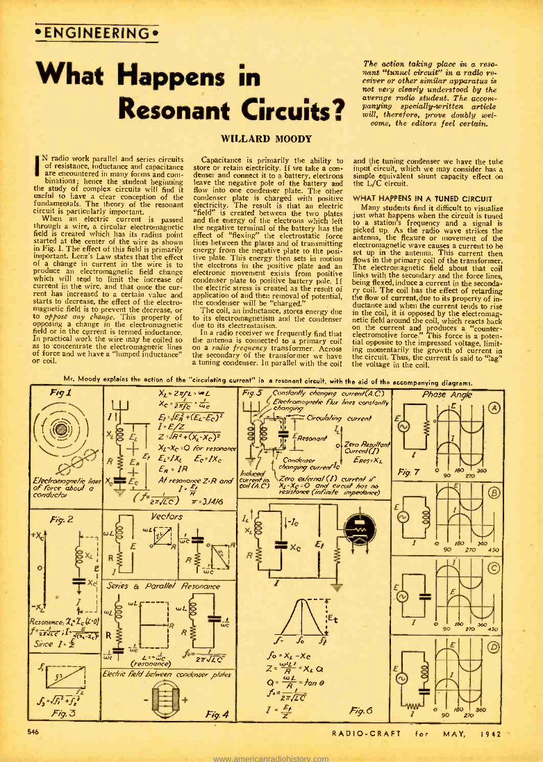
ENGINEERING
What Happens in Resonant Circuits?
N radio work parallel and series circuits of resistance, inductance and capacitance are encountered in many forms and com- binations; hence the student beginning
the study of complex circuits will find it useful to have a clear conception of the fundamentals. The theory of the resonant circuit is particularly important.
When an electric current is passed through a wire, a circular electromagnetic field is created which has its radius point started at the center of the wire as shown in Fig. 1. The effect of this field is primarily important. Lenz's Law states that the effect of a change in current in the wire is to produce an electromagnetic field change which will tend to limit the increase of current in the wire, and that once the cur- rent has increased to a certain value and starts to decrease, the effect of the electro- magnetic field is to prevent the decrease, or to oppose any change. This property of opposing a change in the electromagnetic field or in the current is termed inductance. In practical work the wire may be coiled so as to concentrate the electromagnetic lines of force and we have a "lumped inductance" or coil.
WILLARD MOODY
Capacitance is primarily the ability to store or retain electricity. If we take a con- denser and connect it to a battery, electrons leave the negative pole of the battery and flow into one condenser plate. The other condenser plate is charged with positive electricity. The result is that an electric "field" is created between the two plates and the energy of the electrons which left the negative terminal of the battery has the effect of "flexing" the electrostatic force lines between the plates and of transmitting energy from the negative plate to the posi- tive plate. This energy then sets in motion the electrons in the positive plate and an electronic movement exists from positive condenser plate to positive battery pole. If the electric stress is created as the result of application of and then removal of potential, the condenser will be "charged."
The coil, an inductance, stores energy due to its electromagnetism and the condenser due to its electrostatism.
In a radio receiver we frequently find that the antenna is connected to a primary coil on a radio frequency transformer. Across the secondary of the transformer we have a tuning condenser. In parallel with the coil
Mr. Moody explains the action of the "circulating current" in a resonant circuit, wi
The action taking place in a reso- nant "tunnel circuit" in a radio re- ceiver or other similar apparatus is not very clearly understood by the average radio student. The accom- panying specially - written article will, therefore, prove doubly wel-
come, the editors feel certain..
and the tuning condenser we have the tube input circuit, which we may consider has a simple equivalent shunt capacity effect on the L/C circuit.
WHAT HAPPENS IN A TUNED CIRCUIT Many students find it difficult to visualize
just what happens when the circuit is tuned to a station's frequency and a signal is picked up. As the radio wave strikes the antenna, the flexure or movement of the electromagnetic wave causes a current to be set up in the antenna. This current then flows in the primary coil of the transformer. The electromagnetic field about that coil links with the secondary and the force lines, being flexed,induce a current in the seconda- ry coil. The coil has the effect of retarding the flow of current,due to its property of in- ductance and when the current tends to rise in the coil, it is opposed by the electromag- netic field around the coil, which reacts back on the current and produces a "counter - electromotive force." This force is a poten- tial opposite to the impressed voltage, limit- ing momentarily the growth of current in the circuit. Thus, the current Is said to "lag" the voltage in the coil.
Fig - ̀ \\ / C % )) \\ -i `
J J E/x/rarroçne/ic of force ghoul' conduclor
J
Mes a
1 t
XL, 2nfG = u+L
Xc 2ñfc `"c
Fig S Cons/on/6r ohongr2y a.,,renr(A.C.) E/ecr,cvn /c Aix /vies MnsMn//
Phase Angle / c/,ongnr y E
E o OA ! ,.1----F--- Crowó/inq Gurren/ Er',Eq +(EL-EG)2
tt t t
EResmgn/ c
-r 1 ° Zero Resw//on/ Curren!(I)
E=Xr.
currenl if
Of 1
Fig. 7
pq ° /eo
,r no
MO
Xc
R
X=
t Ec
E. Er
+. E °
1'E/z Z °Rs+(Xc XG)z Xe -Xc :O rôr resonance Ec=lXc Ec=IXe Ert = IR A! resonance Z=R and j ,
I R
_j___
-7 1 Conaé.wvr /1 t c/ronyirg cvawd c
currn+rin l`Zero
px%rna/ (!) ca/(A. C) Xc -Xc = 0 and circui! hor x
reS/s/ance (inrïni/e imoeotsxe) 2n ,479 7r=3/4/6
J +x el C
o
-XL Resonurrce:
f°..;I=.t-=or
Fig. 2
I 2" z,
--, xc :
1
E 1
X ci
1 -- (Z0)
WL
wL
Yecfors
ZL-; t 1 Ic
xc
1
- ° 0 ó
50
r , £! / o /80 3oo
I
E
wc
\ I N I
'
-
-_ I E
© p'T .. Series a Para//e/ f7esonanee
wC w!
,
----1 I wL I
ig we AtEt f % It
.Ìo ' XL-Xe wR L
Q' R=}on B
ieo z sa0 ,g ' R
Since I i E 0 __
© I \
1 î I
wcT ...--wc `fOp,7'+ C (resonance) E/ec/rrc nie/óóefien cwxnser ,o/m'es
r f 27/ I- Et Fi9 6 o
90 /80 960 sao
My % + z f r, +f, Fi9 3
. % Fist 4 546 RADIO -CRAFT for MAY, 1942
www.americanradiohistory.com

However, as soon as an appreciable cur- rent flows in the coil, a potential difference builds up across it (impedance drop = E = IZ) This voltage is then impressed on the condenser, but the condenser has the property of requiring electrons to flow into its plates before it can assume a potential difference between plates. Thus, in the condenser the action is exactly opposite to the action in the coil. The current leads the voltage or the voltage "lags the current" in a condenser circuit.
MEANING OF "Q" AND POWER FACTOR For a pure condenser or coil having no
resistance the angle of lag or lead is 90 degrees. When resistance is introduced this angle is cut down. In a high grade coil or condenser we desire a phase angle as near to 90 degrees as we can get it. In radio work we express the phase angle of a coil in terms of "Q" and of a condenser in terms of "power factor." We desire HIGH Q and low power factor.*
The condenser, once it has become charged from the coil, tends to discharge through the coil and then the coil tends to return the energy to the condenser, so that in effect there is a continuous current trans- fer between coil and condenser, which we call the "circulating current." In a pure condenser or inductance no energy is wasted or lost, and once started the cycle would continue forever. In a practical circuit the coil has a certain amount of resistance and the condenser also has a small amount, so that power is lost in the circuit and new energy must be supplied to it from time to time. In an oscillator this supply of new energy comes from the anode or plate cir- cuit and in our example it comes from the antenna, so that a "fly -wheel action" may take place.
As the result of the voltage lead of the coil and the voltage lag of the condenser, the effect of one is to cancel the other and to make the circuit behave at "resonance" in much the same way as a pure resistance. The condenser lag effect and the coil lead effect, with respect to voltage, is called reactance. The net reactance in the circuit is said to be zero at resonance. This condi- tion holds either for series or parallel reson- ance. The diagram in Fig. 2 illustrates this principle.
At resonance in the parallel of series circuit, the voltage across the coil and con- denser rises, due to the current flowing in the coil and in the condenser. In the parallel resonant circuit these heavy resonant cur- rents balance out, in the series circuit the reactance of coil and condenser exactly balance at resonance but the current in each is identical.
Because for parallel L and C the current is zero externally, when neither coil nor con- denser has resistance, the impedance of the circuit is practically infinite and the line current is zero.
In the series circuit there is zero im- pedance (if coil and condenser have no re- sistance) at resonance and the series current is infinitely great for an infinitely large value of applied voltage.
The use of simple vectors for showing direction of forces is helpful. A vector is a line which indicates by virtue of its direc- tion and length the magnitude and direction of an electric quantity. If we have two forces acting at right -angles, the resultant force will be given by a diagonal as shown in the parallelogram of Fig. 3. Also, if two forces are acting in the same direction or in opposite directions, they will add or sub- tract, according to their relative positions.
WL tanB = -=Q
n c D = B/Z = Power Piaui
RADIO -CRAFT for MAY.
If we have a force of 10 volts acting in a north or positive direction and a force of 5 volts acting in a south or negative direc- tion, the net force will be 10-5 or 5 volts.
The reactance of a condenser or of a coil may be stated in the form of mathematical formulas as shown in Fig. 4. The symbols used and their meanings are given below. I current in amperes E potential in volts Z impedance in ohms R resistance in ohms Xi. inductive reactance in ohms Xe capacitive reactance in ohms e Greek letter (thay -ta) represents phase
angle in degrees L inductance in henries, mh (microhenry
is henry /1,000,000) C capacitance in farads (mf. is farad/ -
1,000,000) w Greek letter (o-mee -ga) represents 2 of f frequency in cycles, kilocycle is 1,000
cycles n a constant, being the ratio of the cir-
cumference of a circle to its diameter or 3.1416
When a parallel circuit of L and C is used in a radio receiver, the impedance of the circuit is a maximum at resonance and is essentially resistive. From ohm's law, we know that the voltage across any circuit is proportional to the product of the current times the resistance. If we know, and we do, that at resonance the line or external cur- rent will be a minimum and that the imped- ance will be infinite for pure inductance and capacitance in parallel (no-resistance in the coil or the condenser) we can readily see that multiplying zero line current by infinite impedance will give a value of voltage across the tank that is also infinite. Because in practice we don't encounter perfect coils or condensers, i.e., units having zero re- sistance, and because the tube input capacity causes detuning and gas within the tube produces a conductive path, there is a cer- tain amount of loading on the tuned circuit, which reduces the theoretical efficiency.
The paradox of infinite impedance at resonance, or very high impedance, and maximum signal seems difficult to grasp for some people. If the action is thought of in terms of energy the matter is greatly sim- plified. The time rate of energy is power - that is so many watts per second. If we assume simply that we have a certain volt- age and current, we can readily see that if the current is reduced to zero (or a very low value) that the voltage in the circuit will rise to a higher value, assuming con- stant power. Thus, E X I equals W. At resonance we have a high current in either branch of L or C, but the net current is zero, since coil current is positive and condenser current is negative (vector quantities). Re- member we are dealing with a voltage in such a circuit. It is the voltage that swings the grid of the tube (the tube is a voltage - operated device) and catrces a plate current variation.
ATTENTION! SERVICEMEN!
Till the Editors what kind of articles you want!
Also send along an article of your own now and then, describing your "pet ideas" for War -Time servicing.
1942
ENGINEERING RADIO MEN! THE "MARINES"
WANT YOU! Lucrative positions are being offered by
the United States Marine Corps to radio specialists between the ages of 17 and 35 who can qualify.
Radio men in this democracy are being urged by their government, through the United States Marine Corps, to help win the war. The leathernecks want all kinds of radio men, from amateurs, right on up to experienced technicians. There's real money in it, too, for men who qualify and - make the grade.
Any radio hobbyist, technician, repair - man-or even a "ham" operator -between the ages of 17 and 35 who can measure up to the qualifications specified by the "devil- dogs ", can take advantage of this opportunity to aid his country and to make some money for himself by enlisting at the nearest Marine Corps recruiting station, as either a Regular, a Class III (c) Re- serve, or a Class V (b) Reserve.
Here's the official word from Marine Corps Headquarters :
Any physically fit man from 17 to 35 who holds or has held an Amateur Radio Operator's License, Class A or B, or a Commercial Radio Telegraph or Telephone Operator's License, First or Second Class, or has certain experience qualifications, can enlist in either of two groups.
In order to make the first, or special radio duty group coming under the Class V (b) Reserves, a radio man must have a high school diploma. And if he hasn't held the licenses called for, he still can qualify. At least three months' experience in radio repairing and servicing, or work in connection with designing or construct- ing high frequency or ultra high frequency transmitting or receiving equipment will put him in this special class, providing, of course, that he's a high school graduate.
With what is called a special warrant, such men will be ranked as Staff Sergeants right after enlisting, without having to go through recruit training. They will be as- signed immediately to a signal battalion for special training in Radio Aircraft Warning maintenance, known as RADAR.
The second opportunity covers those who haven't finished high school but who can qualify as to the license requirements ap- plying to the special warrant group, or if they lack those, can meet the specifica- tions on the basis of a certain amount of practical experience.
This experience can be actual repair and service of radio equipment for at least three months. They can join the Marine Corps either as regulars or reserves. The reserves in this group would come under Class III (c).
These men, without a high school diplo- ma but with some practical radio experi- ence, are sent through recruit training, just like men in line for general military duty. After learning marching drill and the correct Marine way of handling rifle, pistol and bayonet, they attend radio school to prepare themselves for general radio duties. Failure in radio school would put these men into general line duty, for they are not entitled to special rank upon en- listment.
Men in both groups, however, must meet the regular physical requirements for en- listment, although in special cases where a radio man's experience would prove ex- ceptionally valuable, some of the qualifi- cations might be waived.
Anyone interested in radio duty with the United States Marine Corps can go today to the nearest recruiting station or to his local post office.
547
www.americanradiohistory.com
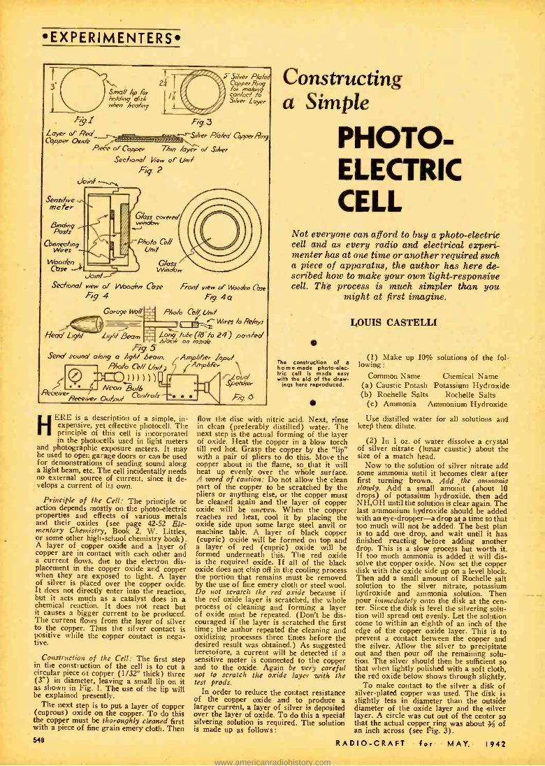
EXPERIMENTERS
F%91
Layer d' Red Cgoper Anote
Small /p /'« hotd,ng drk ss/ien heohn9
Sensi /rve reefer
Binding
Conrrec%ng Wires n, Secírono/ view of Nboohn Cose
fig 4
Garoge MS/
/ï i S Silver Pl /fd / eI Coppe. Ring / / /br moti g / con /oc/ fo S,/ve. Layer
Fg.3 s-_ ---'-Biser Rieke' CcyPerRng
Piere of Copper Tho /ayer of Shier
Secf,onm/ 1/-row of !/+r/
Joint Fi'y. 2
G/oss covered w,ndo..
-P/rk Ce// C/o//
Head Lgr,/
.4.
Fion/ view of Psboof n (bee
44 P/ro% Ce Uni/
q Wires lo Pe /qs
Lrgrf/ Beam LNoong:;te (/s 24) panted Fig. 5
Send srounod along o /ig/ hewn. Ample Per P/ra/o Ce/ Und; f A^mpbFer \
>>))))g:. dti Spee.
fì{iK`eirer Neon Bu/6
Con/ro/s -L.l\
Receivei tr/prd --. Fig 6
ERE is a description of a simple, in- expensive, expensive, yet effective photocell. The pnnciple of this cell is incorporated in the photocells used in light meters
and photographic exposure meters. It may be used to open garage doors or can be used for demonstrations of sending sound along a light beam, etc. The cell incidentally needs no external source of current, since it de- velops a current of its own.
Principle of the Cell: The principle or action depends mostly on the photo-electric properties and effects of various metals and their oxides (see page 42 -52 Ele- mentary Chemistry, Book 2, W. Littles, or some other high -school chemistry book). A layer of copper oxide and a layer of copper are in contact with each other and a current flows, due to the electron dis- placement in the copper oxide and copper when they are exposed to light. A layer of silver is placed over the copper oxide. It does not directly enter into the reaction, but it acts much as a catalyst does in a chemical reaction. It does not react but it causes a bigger current to be produced. The current flows from the layer of silver to the copper. Thus the silver contact is positive while the copper contact is nega- tive.
Construction of the Cell: The first step in the construction of the cell is to cut a circular piece or copper (1/32" thick) three (3 ") in diameter, leaving a small lip on it as shown in Fig. 1. The use of the lip will be explained presently.
The next step is to put a layer of copper (cuprous) oxide on the copper. To do this the copper must be thoroughly cleaned first with a piece of fine grain emery cloth. Then 544
Constructing a Simple
PHOTO- ELECTRIC CELL
Not everyone can afford to buy a photo -electric cell and as every radio and electrical experi- menter has at one time or another required such a piece of apparatus, the author has here de- scribed how to make your own light-responsive cell. The process is much simpler than you
might at first imagine.
The construction of a h o m e -made photo -elec- tric cell is made easy with the aid of the draw-
ings here reproduced.
LOUIS CASTELLI
(1) Make up 10% solutions of the fol- lowing :
Common Name Chemical Name (a) Caustic Potash Potassium Hydroxide (b) Rochelle Salts Rochelle Salts
(c) Ammonia Ammonium Hydroxide
flow the disc with nitric acid. Next, rinse in clean (preferably distilled) water. The next step is the actual forming of the layer of oxide. Heat the copper in a blow torch till red hot. Grasp the copper by the "lip" with a pair of pliers to do this. Move the copper about in the flame, so that it will heat up evenly over the whole surface. A word of caution: Do not allow the clean part of the copper to be scratched by the pliers or anything else, or the copper must be cleaned again and the layer of copper oxide will be uneven. When the copper reaches red heat, cool it by placing the oxide side upon some large steel anvil or machine table. A layer of black copper (cupric) oxide will be formed on top and a layer of red (cupric) oxide will be formed underneath this. The red oxide is the required oxide. If all of the black oxide does not chip off in the cooling process the portion that remains must be removed by the use of fine emery cloth or steel wool. Do not scratch the red oxide because if the red oxide layer is scratched, the whole process of cleaning and forming a layer of oxide must be repeated. (Don't be dis- couraged if the layer is scratched the first time ; the author repeated the cleaning and oxidizing processes three times before the desired result was obtained.) As suggested heretofore, a current will be detected if a sensitive meter is connected to the copper and to the oxide. Again be very careful not to scratch the oxide layer with the test prods.
In order to reduce the contact resistance of the copper oxide and to produce a larger current, a layer of silver is deposited over the layer of oxide. To do this a special silvering solution is required. The solution is made up as follows:
Use distilled water for all solutions and keep them dilute.
(2) In 1 oz. of water dissolve a crystal of silver nitrate (lunar caustic) about the size of a match head.
Now to the solution of silver nitrate add some ammonia until it becomes clear after first turning brown. Add _the ammonia slowly. Add a small amount (about 10 drops) of potassium hydroxide, then add NH.OH until the solution is clear again. The last ammonium hydroxide should be added with an eye -dropper -a drop at a time so that too much will not be added. The best plan is to add one drop, and wait until it has finished reacting before adding another drop. This is a slow process but worth it. If too much ammonia is added it will dis- solve the copper oxide. Now set the copper disk with the oxide side up on a level block. Then add a small amount of Rochelle salt solution to the silver nitrate, potassium hydroxide and ammonia solution. Then pour immediately onto the disk at the cen- ter. Since the disk is level the silvering solu- tion will spread out evenly. Let the solution come to within an eighth of an inch of the edge of the copper oxide layer. This is to prevent a contact between the copper and the silver. Allow the silver to precipitate out and then pour off the remaining solu- tion. The silver should then be sufficient so that when lightly polished with a soft cloth, the red oxide below shows through slightly.
To make contact to the silver a disk of silver -plated copper was used. The disk is slightly less in diameter than the outside diameter of the oxide layer and the silver layer. A circle was cut out of the center so that the actual copper ring was about h of an inch across (see Fig. 3).
RADIO -CRAFT for MAY, 1942
www.americanradiohistory.com

A method quite satisfactory for plating the copper with a layer of silver is to place the copper in a solution (dilute) of silver nitrate. A gray scum will collect about the copper and some of it will collect and plate on the copper. When the first scum has col- lected on the copper, remove the copper and rinse in distilled water. Then place in the 'solution again. Continue this until the copper is completely covered with silver. The cop- per ring can also be plated by using a solu- tion of silver and potassium cyanide and a bar of silver as a positive electrode.
It is perhaps more satisfactory to enclose the unit in a wooden case, turned up on a lathe especially for the purpose. The silver side of the unit must face toward the light in order to have the device generate a cur- rent.
USES OF THE METER (1) The unit can be used as an exposure
meter by merely connecting the unit across a sensitive meter and calibrating the meter scale, by using some meter of standard manufacture as a calibrating standard. To make the meter easy to carry around it can be placed in a specially made wooden case, which can be turned on a lathe (see Figs. 4 and 4a).
(2) The unit can be used to open garage doors and by using the suggested hookup, the unit will operate both day and night- (see Fig. 5).
(3) The unit can also be used to demon- strate the "sending of sound along a light beam." This is accomplished by connecting a neon bulb directly across the output of a receiver and having it focus onto the photo- cell, which is connected to the input of a small amplifier.'The variations in the voice current at the output of the receiver are manifested as variations in intensity in the light emitted by the neon bulb. The neon bulb will follow these rapid variations. When the photocell picks up these varia- tions ii intensity of the light, it re -forms the light variations into changing varying electric current, and this is amplified by the amplifier and changed into sound again by the loudspeaker (see Fig. 6).
THE
EDITORS
WANT
good constructional articles Iw i t h clear photos and diagrams), Radio Receivers and other sets, especially "FM" Tuners and Adapters. We also are anxious to see con- structional articles on Short Wave Receivers; also general articles on Antennas, etc.
RADIO -CRAFT for MAY, I
EXPERIMENTERS
5 -Tube AC -DC Super -het Kit Using a small number of tubes. this Meiss- ner engineered 5 tube AC-DC super -het is compact in size and contains a factory wound loop antenna. Only two controls are used, making the set very simple to operate. It's simple to build .. you can easily follow the schematic and pictorial wiring diagram. The Kit is complete -there is nothing else to buy. Kit with tube-- $51.25 list.
5 -Tube AC T. R. F. Kit llare's a It that is lose in cost and high in quality. Operates from 110 soit '0 -60 AC with a frequency range of 530 to 1600 ke. 1187 to 565 meters). Complete. kit includes all parts necessary for construction of the receiver with exception of tubes and speaker. Meissner pictorial diagrams make this set extremely easy to build. Kit -$27.00 list.
4 -Tube AC -DC T. R. F. Kit here is a very small ffKIIDICI, receiver with exceptional sensitivity and tone quality. Frequency coverage of 53M
to 1600 kc. Compact. high gain shielded mils are tuned with two gang precision toning condenser. Provision for mounting 5' dynamic speaker. Kit contains all pane exrept tubes and speaker. Pictorial diagrams aid you to construct this receiver easily and quickly. Kit -$19.50 list.
See your t Meissner jobber. Write for complete new catalog.
Address Dept. CT -5.
MT. CARMEL. ILLINOIS
"PRECISION -BUILT PRODUCTS"
NEW SAN FRANCISCO SHORT- ' WAVE STATION
O. F. Walker, radio engineer of the Gen- eral Electric Company, has been supervising the installation of a 100,000 -watt short- wave transmitter in San Francisco, which will be another gun in a kilocyclic battery "shooting" from the United States across the Pacific in the propaganda war with Japan.
The powerful transmitter, built by Gen- eral Electric and operated previously at its Schenectady station WGEO for short- wave broadcasts to Europe and Latin Amer- ica, will be operated in San Francisco un- der call letters KWID. Operators of the station will be Associated Broadcasters, Inc., operators of long -wave station KSFO. Gen- eral Electric is completing another 100,000-
942
watt transmitter for WGEO at Schenec- tady and meanwhile is on the air there with two other short-wave transmitters, WGEO and WGEA.
KWID, which will have studios and offi- ces at the Hotel Mark Hopkins, will render additional short -wave service to that now being given by General Electric's 50,000 - watt San Francisco station KGEI, with studios and offices at the Fairmont Hotel. KGEI has been broadcasting to Latin America, Asia, the Antipodes, and Africa for more than three years, and is at pres- ent the only United States short-wave broadcasting station west of the Missis- sippi. KGEI is now broadcasting in eight languages and two foreign dialects.
549
www.americanradiohistory.com

EXPERIMENTERS
HOME -MADE ARC LAMP JOE NONWICZ
From a few scrap parts easily found in your "junk box," this home -made arc lamp can be constructed.
THIS simple arc lamp with automatic feed is suitable for use as a sun tan lamp, and can be built entirely of junk parts found in the average experi-
menter's shack. The frame for the lamp is made of a
strip of metal 3" wide and 32" long, another piece 3" wide by 6" long is needed to hold in place the porcelain tube on which the coil is wound, and two more 2" by 10" strips are required for braces. The base is a piece of 1" by 12" wood, which must be large enough to house the lamp, the switch, and the choke or resistance, which- ever is used. A 7%" piece of V" iron rod together with the coil serves as the auto- matic feed. Two condenser shaft couplings %" to 4" or %" to %" (the size depend- ing on the size of the carbons used) are the carbon holders, the %" to a" size being suitable for use with flashlight bat- tery carbons, since they are about h" in diameter.
Construction is started by drilling %" hole in the center of the 3" by 32" strip and also in the center of the 3" by 6" piece, both of these strips are then bent to make a right -angle 2" each side of cen- ter, then 2" from each end of the 3" by 32" strip, another right -angle is made. A porcelain tube of the type used in wiring is now inserted into the hole in the frame and the 3" by 6" piece of iron or other metal is so placed inside the frame, that the bot- tom of the tube is even with the bottom 550
of the strip. This position is marked and holes are drilled for bolts to hold it here. A hole slightly larger than %" is drilled in a 1%" by 1%" piece of brass and a %" bushing is mounted directly over the hole and the whole piece is bolted onto the 3" by 6" strip directly over the ;/2" hole. the braces are made by folding the two 2" by 10" strips lengthwise into a right- angle, and then cutting along this fold for l %" and folding these two halves into a box corner, holes are then drilled in the braces and frame and the braces are bolted to the base. A piece of asbestos is put over the hole of the frame, the porcelain tube is inserted and a coil of about ten layers of No. 16 wire is wound on the tube. The 3" by 6" piece with the bushing on it is now bolted in place and the frame is bolted to the base. The rod is inserted into the coil, the place where the rod touches the base is marked and a %" hole is drilled here. A 1" piece of %" bolt is put through a 1%" by 1%" piece of brass, which is bolted to the base so that the bolt falls directly over the '" hole in the base. Condenser shaft couplings are now put on, one on the shaft and the other on the '4" bolt, carbons are inserted into the empty ends of the couplings and the lamp is wired according to the diagram.
When the lamp is wired plug it into the 110 volt outlet and turn it on. The lamp should strike an arc and keep it going, but if the arc does not strike and the ends of
A self - feeding arc -lamp suit- able for sun -tan treatment, etc:, is illustrated and de- scribed by the author. Stan- dard arc carbons are used and the cost of building the lamp is very lote -a good "de- fense" project, as it can be built from "scrap box" parts.
the carbons get hot, this means that the rod or the carbons are too long. When this happens, the rod or carbons should be shortened, but care should be taken not to cut too much of the rod off, as it will fall out of the coil when the carbons burn clown.
If the lamp is to be used on D.C. a re- sistance of about 6 to II ohms should be substituted for the choke. If the lamp is turned on and the top carbon jumps up and down without striking an arc, the carbons are too large and smaller carbons should be substituted.
The lamp will work entirely without attention, once the proper size and length carbons are in place, as the solenoid (suc- tion) coil will lower the top carbon auto- matically as the carbons burn down.
The iron rod which holds the carbon and which slides freely in the coil is 7;4" lung, so theoretically it would be possible to use carbons 1a" long, since the coil would pull the iron rod up until she rod was in the center of the coil, but I use carbons approximately 2" long as part of each carbon is taken up by each coupling, thus leaving a little less than la" of use- ful carbon. \When the lamp is turned on, the resistance between the carbons is very low; this causes the carbon to jump up since the coil current is high, thus striking the arc. Sometimes the carbon doesn't vaporize instantly and the carbon jumps up and down, but once the carbon vapor- izes and the arc starts, the lamp keeps a steady arc going, because as the top carbon gets too close to the bottom one the re- sistance is lowered and more current flows through the coil. This increases the attrac- tion of the coil for the rod, thus raising the iron rod to which the carbon is at- tached and thus pulling the carbons apart, until the coil current drops to a certain value, at which the carbon becomes prac- tically stationary. As the carbons burn down the resistance increases and the coil current drops, causing the carbon to drop until a certain current value is reached, when the carbon again becomes practically stationary.
Those interested in making a very smooth- working arc lamp will do well to study one of the commercial arcs. Pay special atten- tion to the simple but effective design of the clutch used to lift the carbon in the com- mercial apparatus. Also a dashpot is desir- able to prevent the spasmodic, jerky action of the arc mechanism usually encountered when the dashpot is not employed.
Also experiment with the amount of re- sistance in series with the are; increasing this ballast resistance will sometimes vastly improve the action of the art. Ed.
RADIO -CRAFT for MAY, 194;
www.americanradiohistory.com

ALMOST everyone whose interest in radio extends beyond that of the ordi- nary radio listener realizes the dis- advantages of fluctuating line voltage
when applied to a radio transmitter, re- ceiver, test oscillator, vacuum -tube volt- meter or almost any other line- operated radio or test equipment. Usually if one finds that his line voltage varies materially from hour to hour or day to night, he simply considers himself unfortunate -and suffers in silence.
If he is a ham whose transmitter tubes require constant filament voltage for proper life and operation, he sticks a rheostat and voltmeter in the circuit and, keeping an eagle eye on the voltmeter during operation, manually adjusts the rheostat from time to time as line voltage variations require. If he is either a ham or short -wave listener he may find that his communications type re- ceiver varies in sensitidlty, or if it has an "S" meter, that the zero setting of this meter refuses to "stay put," with the result that he must make frequent adjustments of the zero-setting control if the meter is to continue to give anything like its normal indications for given signal inputs. In test work any test equipment which employs vacuum -tubes will very probably have its calibrations thrown off when the line supply voltage varies.
It isn't by any means necessary to grin and bear such bothersome variations. At very little cost anyone who has the ability to build and wire the simplest type of radio equipment can build himself an automatic line -voltage regulator that will do an ex- cellent job. The simple unit to be described here, for instance, proved capable of holding the voltage applied to a communications receiver constant within plus or minus 2 volts, with the line varying between 105 and 130 volts.
The heart of this regulator is the Am- perite self- adjusting line voltage control. In appearance this is similar to a 6L6G tube, but its internal element is a grid of re- sistance wire which has as its most note-
EXPERIMENTERS
Build Your Own
Automatk VOLTAGE
REGULATOR High -class receivers, such as those of the "Com- munications" type, require a fairly constant line voltage for their proper operation. The automatic home -built voltage regulator here described by Mr. Taylor was found on actual test to hold the line voltage extremely constant.
Fig. 2 One of the photos shows the voltage regulator at right of SX -28 receiver. Other photo shows ap- pearance of home -built automatic voltage reg-
ulator.
worthy characteristic the ability to auto- matically vary its resistance over a wide range in order to maintain current flow constant. Thus, this is a real "ballast" tube and is not to be confused with the resistance tubes employed in many AC /DC receivers, sometimes incorrectly called "ballast" tubes, but which in reality are just another form of fixed resistor.
When a ballast tube is connected in series with the load to be controlled, a rise in line - voltage will cause the resistance of the Amperite to increase. This in turn results in an increase in the voltage drop across the tube approximately equal to the increase in line voltage. The voltage applied to the load therefore remains unchanged. On the other hand, should the line voltage fall below its normal level the resistance of the ballast will automatically decrease, and also the voltage drop across it.
t9ne can think of these ballast tubes either as constant- current devices, or as voltage regulators. The important thing is not the terminology but the performance. The per- formance characteristic of a typical Am- perite is shown in Figure 1. Here it will be seen that as the applied voltage is increased from zero the current flow increases rapidly at first, then remains constant during con- tinued voltage increase and finally again starts to rise. The best regulation is, of course, obtained over the flat portion of the current -voltage characteristic which, in the particular ballast represented in Figure 1
(and applies to all other ballast as well) shows variation of 200 percent or more in the voltage drop for a 10 percent change in current flow.
The ballast tube always presents some re- sistance to the circuit in which it is included. Thus if the ballast of Figure 1 were in- cluded between a 115 -volt line and a load rated at 0.63 amp., 115 volts, the load would not receive its normal voltage, but instead would have applied to it the voltage of the line, less the drop across the Amperite. In order to apply 115 volts to the load, there- fore, it is necessary to first provide means
S. GORDON TAYLOR
for stepping up the line voltage to a higher level. An alternative would be to include in the controlled device a power transformer having a primary rating of some value lower than 115 volts.
From the curve of Figure 1 it is seen that at the midpoint of its flat portion, there is a drop of 20 volts across the ballast. If a trans- former were connected to first raise the line voltage by this amount then the voltage ap- plied to the load would be the required 115 volts. Or the transformer in the load could have a 95 -volt primary, in which case the load would receive its proper supply from the 115 -volt line, after the ballast drop.
It is rather difficult for the home con- structor or experimenter to alter the pri- mary winding of the power transformer in the receiver or other equipment to which the control is to be applied. It is a simple matter, however to step up the line voltage to the required higher level by means of a small transformer, which adds anywhere from 20 to 25 volts to the line.
HOME -BUILT REGULATOR Figure 2 shows a home -built regulator
unit utilizing such a transformer. The circuit is shown in Figure 3. The transformer is a standard filament type with three second- aries of 7.5 volts each. These are connected in series- aiding to provide 22.5 volts, and also in series with the primary so that this voltage is added to that of the line. In effect, the unit thus connected is an autotransformer giving a total output of 137.5 volts from a 115 -volt line.
The only other essential components are the ballast tube and a standard 4 -prong tube socket into which it mounts. As a matter of convenience a standard 2 -prong receptacle was also included in the regulator shown and the load plugs into this.
This unit was built to control the supply voltage to a Hallicrafters SX -28 communi- cations receiver when used in a location where the line voltage was abnormally high during the day, and dropped way below its rated value when the lighting load went on at nightfall, only to rise to abnormal levels again when the neighborhood went to bed. Its effectiveness is shown by the figures of Table 1.
In employing a voltage regulator of this
RADIO -CRAFT for MAY, 1942 551
www.americanradiohistory.com

EXPERIMENTERS type to control the supply to vacuum -tube equipment there is just one precaution to be taken. This is made necessary by the fact that the ballast does not vary its resistance instantaneously, nor do vacuum -tube devices draw full current at once. The operating principle of the ballast tubes is based on (1) the rise of temperature of the resistance wire with current flow, and (2) an increase in the resistance of this wire as its temperature increases. Its cold resistance is very low. When the power is turned on it requires a few seconds for the wire to heat and its resistance to rise to the required level. This means that very nearly the full stepped -up voltage will be applied to the load during these few seconds. Then, the load itself may not draw full current at once (in the case of a radio set that does not start drawing plate current until after the filaments have warmed up, for instance). In that case the subnormal load current will result in rela- tively small drop across the ballast and will continue to allow excessive voltage to be applied to the load until the filaments are completely warmed.
A simple way to overcome both of these difficulties at the same time is to utilize a 3- position switch for the power switch, as shown in Figure 4. l'osition 1 is the off position. When turned to position 2 the line voltage (without boost) is applied directly to the load. But more than this, the 22.5 -volt output of the booster transformer is applied
In order to select the proper ballast for regulating the voltage to any particular load it is necessary to determine the current drawn by that load at its normal 115 -120 volt input. Then it is necessary to understand the method of rating standard ballast tubes.
HOW "BALLASTS" ARE RATED Ballasts are rated according to their effec-
tive threshold current, or that which will bring them to the beginning of the flat por- tion of their current -voltage characteristics, such as the point (A) in Figure 1. Their most effective current range extends upward 10 percent from their rated values and at this higher extreme the voltage drop devel- oped will be at least 200 percent greater than the threshold voltage. There are 12 standard types available, with ratings of 0.2, 0.3, 0.4 and so on up to 1.3 amperes. These ratings are indicated by the type numbers 2A5, 3A5, 4A5, etc.
Now, suppose we have a device which we wish to control and measurement shows that at normal rated line voltage it draws 0.75 amp. The 7A5 ballast is suitable inasmuch as its effective range extends from 0.7 to about 0.77 amp. (threshold rating plus 10 percent). The range of voltage regulation would be somewhat better if the normal load current fell more nearly in the center of this current range but nevertheless will be good. I f, on the other hand, the normal load cur- rent of the device were 0.7 amp. instead of
last types are better than that indicated by the curve of Figure 1, in that many of them will show voltage drops extending to 40 volts or more before passing current 10 per- cent in excess of their threshold rating. This is particularly true of ballast designed for use with currents below 0.5 ampere.
These voltage regulator tubes are capable of dissipating 40 watts in continuous service, which means that they are suitable for con- trolling loads up to 150 watts and higher.
They need not, of course, be employed externally. The components of a unit such as that of Figure 2 could in many cases be included right in the assembly of the device that is to be controlled. Thus where such a combination is included to regulate the volt- age to the filaments in a transmitter, the booster transformer and ballast tube could be mounted on the transmitter chassis. In such an application the same regulator could be employed to control the supply to several filament transformers as shown in Figure 5. In this case however, no provision should be made for switching off any of the individual filament circuits separately, because this would result in the application of higher than rated voltage to the filaments left in the circuit.
It should be obvious that, because they are pure resistive devices, these ballast tubes are applicable to both AC and DC circuits. Their only limitation in DC circuits is that there is no means for boosting the supply voltage
h-Over 2170% increase -+1 A 1
n vd/oSx oto,o across bal/arti
6
4 v .2
s I._. c:o'c:oc
/0 /5 20 25 30 35 Vo //age Drop Across Ba //as/
Fiq.1
IO
To AC Line
Load Receplock
O A. . L ine
7.5V.
7.51/
7.5 V.
Amper /e 6A5
F,y: 3
Fig. 5
To Trorxsnx%//ei Fi/amends
Fig. I: Control characteristic of a typical ballast regulator tube (Amperite type 6A5). Any tendency toward current change as a result of increasing line voltage causes compensating increase in the voltage drop across the ballast, thus maintaining substantially constant voltage at the load. Fig. 3: Circuit of the unit shown in photos. A filament transformer, with all windings in series, provides the booster voltage. Fey. 4: The circuit of Fig. 3 with 3- position power switch added to prevent application of excessive voltage while ballast and receiver tubes are warming up. Fig. 5: Several "load" circuits can be controlled through a single regulator unit.
directly across the ballast. Thus if the switch is left in this position for 20 seconds or so, the tube filaments will heat up and plate current will start to flow. In the meantime the voltage applied to the ballast will have brought it up to approximately the required operating temperature. Thus when . at the end of about 20 seconds the switch is thrown to position 3 both the load and resistor are ready for the application of the higher supply voltage.
The SX -28 receiver draws about 0.85 ampere from the line and the ballast em- ployed in the unit of Figures 2 and 3 is there- fore the Amperite type 8A5 (the first num- ber of the type designation indicating that it is for use with loads drawing about 0.8 ampere).
552
0.75 the regulation would be less satisfactory because downward variations of line voltage would carry the ballast onto the sloping portion of its curve. However, in this case it would be a simple matter to increase the load current slightly by means of a shunt resistor so that the total drain at normal input voltage would be about 0.735 amp. This would bring the load right into the center of the operating range of this ballast, with maximum range of regulation as a result. Likewise if the normal load current were say 0.77 or 0.78 amp. better regulation would be obtained by shunting a resistor across the load to increase the total current to about 0.84, then use a type 8A5 ballast which has an effective current range of 0.8 to 0.88 amp.
Actually the effective range of many bal-
to compensate for the drop inherent in the ballast. \Vherc the required load voltage is less than the line voltage, these automatic ballasts make perfect voltage dropping re- sistors because they not only drop the volt- age, but regulate it as well. Two of them can be used in series if necessary to provide large drops.
Line Voltage 105 110 115 120 125 130
RADIO -CRAFT
TABLE I Regulated Voltage
Applied to Load 111 ' 113 113 113 114 115
for MAY, 1942
www.americanradiohistory.com

BOOK REVIEW
MATHEMATICS -ITS MAGIC AND MASTER. by Aaron Bakst. Published by D. Van Nostrand Company, Inc., Cloth covers. size 5% z 8% ins.. 790 pages. Price $3.95.
This book furnishes a new and interesting way for you to master mathematics by under- standing its many valuable and practical every- day uses. It is designed to make mathematics interesting.
Although this book is designed for amusement, it is not restricted to novel, tricky and enter- taining mathematical stunts merely. Some in- teresting subjects treated are systems of numeration, secrecy in numbers, simple cal- culating devices, problems and puzzles, algebra and its numbers, chain -letter algebra, stream- lining everyday computation, postoffice math- ematics, and the grammar of algebra.
In these pages the reader will learn the vital part mathematics plays in every office and shop -in engineering, mechanics, aviation. science, accounting. banking -in the feats of number magicians (which give you many "short- cuts" and "time- savers "), in figuring the best play in games of chance. and in hundreds of other fascinating recreations. All these practical ap- plications of mathematics are fully explained in plain English.
MATHEMATICAL TABLES, by Herbert Bristol Dwight, D.Sc. Published by McGraw -Hill Book Company Inc., Cloth covers, size 6 z 9% ins.. 232 pages. Price $2.50.
Here is a book which any person who has to do mathematical work will find very useful. The arrangement of the tables contained in this book is concise, which leads to great convenience.
In the trigonometric tables in this book. decimals of degrees, to 1 /100 degree, are used instead of degrees, minutes and seconds which are in many ways less convenient than decimals. The same advantages of a decimal system are found in these tables, that are experienced in the use of meters and centimeters in place of feet and inches.
In the use of the tables contained in this book, a good number of significant figures are needed, not only in the value of the function but in that of the argument. To obtain the latter, inter- polation is used. and this can be done much better if the differences are given. Differences are shown at the right-hand side of practically all the tables in this book.
DRAKE'S CYCLOPEDIA OF RADIO AND ELECTRONICS, Tenth Edition. by Harold P. Manly and L. O. Gorder (1942). Published by Frederick .1. Drake & Co. Size 6 z 9 Inches, cloth covers. Price $5.00.
This large volume, profusely illustrated, has the subjects arranged in alphabetical order and will prove most useful to students as well as to the more advanced radiomen.
Many of the diagrams have been specially prepared for this book and they help in a very clear manner to explain the action taking place in vacuum tubes, various radio circuits, etc.
One thing the reviewer likes about this book is that it is very complete and covers such interesting radio topics as aviation radio and landing beams -with very clear explanatory dia- grams; storage batteries and their performance; photo cells of various types, with a number of valuable circuits for operating photo -cell relays under different conditions, etc. The inductance of coils and inter -related circuits is nicely cov- ered and the section on filters is very informa- tive.
Other vital subjects covered are loop antennas and their action; measuring instruments and how they work. including vacuum -tube meters; how and why of modulation; public address sys- tems; electric phonographs; short-wave and broadcast receivers -with special treatment of the superheterodyne and how it works.
The final sections of the book deal with resonance, selectivity, shielding, sound, sound pictures, loudspeakers, radio symbols, cathode - ray tubes, television, circuit troubles and how to locate them, various types of special tubes - including the grid -glow tube.
AUTOMATIC RECORD -CHANGERS AND RE- CORDERS, by John F. Rider. Published by John F. Rider Publisher. Inc. Cloth coven. sise 8% x 11rá inches, 744 pages. Price $6.00.
Radio Servicemen will find that this book will give all the general and specific facts about the record- changers and recorders now in the hands of the public. Every Serviceman will find this book very useful during the coming years. as he will have available a reliable source of specific information.
The subject of small electric motors has been dealt with quite extensively in the text section of this book. Also the control of their speed is explained.
Due to the fact that a great many recorders have appeared upon the market lately, and as these devices are so closely allied with automatic record -changers, a description of their mech- anism. its functioning and operation has been included, together with data concerning methods
RADIO -CRAFT for MAY, I
of recording, records, and cutting needles. The same is true of the electric phonograph. A description will be found of the several types of pick -ups and needles, as well as their care and proper operation.
The latter portion of the book is devoted to the manufacturers' service data, which covers practically all the automatic record- changers and recorders on the market at the time the book was written (November 1941).
The book is divided into four chapters, viz.: Chapter I. Motors and Drives; Chapter II. Re- corders and Phonographs; Chapter III, Auto- matic Record- Changers; Chapter 1V, Analysis of RCA Model RP -152 -C Record- Changer. It is profusely illustrated.
THE RADIO AMATEUR'S HANDBOOK - "Special Defense Edition." Published by The American Radio Relay League, Inc., West Hart- ford, Conn. Flexible paper covers. sise 6% z 91 inches. Illustrated.
The well -known Radio Amateur's Handbook has been brought out in a new dress. labeled "Special Defense Edition."
This edition, besides containing the nine basic theoretical chapters included in the standard edition, contains a chapter covering the elemen- tary mathematics necessary for the solution of all formulas and interpretation of graphs ap- pearing throughout the text. This includes a review of decimals, method of extracting square root, algebraic notation and manipulation of formulas, laws of exponents, logarithms, a discus- sion of linear, power and exponential functions and their application to graphs, and the use of polar coordinates. Supplementing this chapter. a four -place log table is included in the Appendix.
The constructional chapters contained in the regular edition have been condensed into one new chapter. Data on and photographs of the more generally -used commercial receivers and trans- mitters are included.
Included in this book is a new chapter on learning the radio telegraphic code. Its treatment is based on up- to-date methods of learning by hearing. This can be used either for self- instruc- tion or for the guidance of those interested ir. giving code classes.
The complete list of chapter headings is as follows: Formulas and Graphs ; Electrical and Radio Fundamentals; Vacuum Tubes ; Radio - Frequency Power Generation ; Radio-telephony ;
Keying; Receiver Principles and Design ; Power Supplies; Wave Propagation; Antenna Systems: Radio Equipment; Measurements and Measuring Equipment; Workshop Practice; Learning the Code; and Appendix (useful formulas, data and charts).
MATHEMATICS FOR RADIO AND COMMUNI- CATION, by George F. Maedel. A.B., E.E. Pub- lished by Maedel Publishing House, Brooklyn, N. Y. Cloth covers, size 9% z 6 ins. Two volumes: Book 1. 314 pages; Book II, 329 pages.
Mr. Maedel is chief instructor at the RCA Institute's Radio School in New York. In order to be a good radio technician today one must have a very thorough background in mathematics and these two books by Mr. Maedel cover the ground thoroughly, and without waste of the readers' time in studying a lot of unrelated mathematics. These two books are official texts on mathematics in the school in which the author teaches.
Book I covers algebra, geometry and arithmetic, while Book II coven advanced algebra, trigo- nometry and complex numbers. Several interest- ing chapter titles from the two books on radio mathematics are: Addition, Subtraction, Multi- plication and Division in Arithmetic; Definition and Symbols; Factoring; Decimals and Powers of ten : The Metric System ; Engineering Prob- lems and the Slide Rule; Solid Geometry ; Alge- braic Formulas, Logarithms and Decibels, Trigo- nometric Functions. The Binomial Theorem; etc.
TECHNICAL REVIEW Hy'grade Sylvania recently brought out a tube
simplification chart, showing which type of Sylvania tubes may be used to replace various other types of tubes. In some cases one of the new type tubes may be used to replace as many as three different older types of tubes. Every radio Serviceman should have a copy of this tube simplification chart, as it will save him a great amount of time. (Hygrade Sylvania Corp., Emporium, Pa.)
942
BOOK REVIEWS.
PRAC*IC RA01 NFORMAWEON Including Frequency Modulation- Television, etc.
I aside Radio I nformnt Ion (orali Servicemen- Aircraft Pilots, Students. AI'I)1.1.S RADIO - IIANS GUIDE contains 772 Paps, 400 Diagrams 1, Pbgbs in complete -gives Authentic Principles & Practices inCon- struction, Operation. Service & Repairs. Covers clearly and concisely Radio fundamentals -Ohm's Law -Physics of Sound as related to radio sci- ence- 1feseunng Instruments -Power Supplyy-Resistors- Inductors- Condensers - Transformers and examples-- Broadcasting stations -Radio
Telephony-Receivers-Diagrams -Construction- Control systems - Loud speakers - Antenna systems
-Auto Radio -Phonograph pickups-Public Ad- dress Systems -Aircraft & Marine Radio -Radio Compsas- Beacons- Automatlo Radio Alarms - Short Wave -Coil Calculations- Testing- Cathode ray oecillographs- Statlo Elimination- Trouble Pointers -Underwriter's standards -Units and tables -Frequency Modulation- REVIEW QUES- TIONS & ANSWERS, Ready Reference Index.
SI COMPLETE PAY ONLY $1 A MO. Get this practical Information In handy foam for yourself-Fill In and
MAR COUPON TODAY - AUDEL P Publishers, hers,49 W 23rd St N.Y.
sin. N O. M., I will rend o SI In 7 deys' then remit monthly un0154 Ir paid. ómerwise I will return lt.
Name
Address
Occupation
Reference ItCF
DEGREE IN 24. YEARS .7 Complete Radio Engineering Course In 27
months. Bachelor of Science Degree. Radio (television, talking pictures and the vast electronic geld) offers unusual opportunities. Defense needs call for the engineer. Demand exceeds the supply. Courses also in Civil, Electrical. Mechanical. Chemical. Aeronau- tical Engineering; Business Administration. Accounting, Secretarial Science. Tuition. living costs low. World famous for technl eat 21/4 year courses. Special preparatory department for those who lack required high school work. Enter June, September, January, Morel,. 59íh year. Write for catalog. 2452 COLLEGE AVE. ANGOLA, IND.
TRI-STATE COLLEGE
òmplele Plans For Iln,i.ling l',rfol and
Home.i Each T Issue of Popular Homeeraft is crammed for making such i
plant beau-
tiful tiful and useful things e: FFurniture. Dina
door Oer.t npaF Furni- ture,
etc. Covers lathe wort, leatercq coupe
to You'll
almost everything from the pages of Popular ilomecraft. Scores f drawings and photogry ha make every step simple as A B C. A foal "How- To- Do-It' magasine.
Six Months' Trial $1.00 send 111.00 today for trial six months' subscription
Money Hark If Not Delighted.
POPULAR HOMECRAFT 937 Palmolive Building Chicago, lit.
Trial months $1 °O
COMMERCIAL RADIO INSTITUTE A radio training center for over twenty yeah. Well equipped. Excellent faculty. Practical resi- dent courses in Radio Telegraphy. Broadcast. Servicing, Industrial. Television, Aeronautical, Drafting, Mathematics and Studio Technique. Placement bureau. Classes now forming. Catalog upon request. Dept. D, 38 West Biddle Street, Baltimore, Md.
553
www.americanradiohistory.com
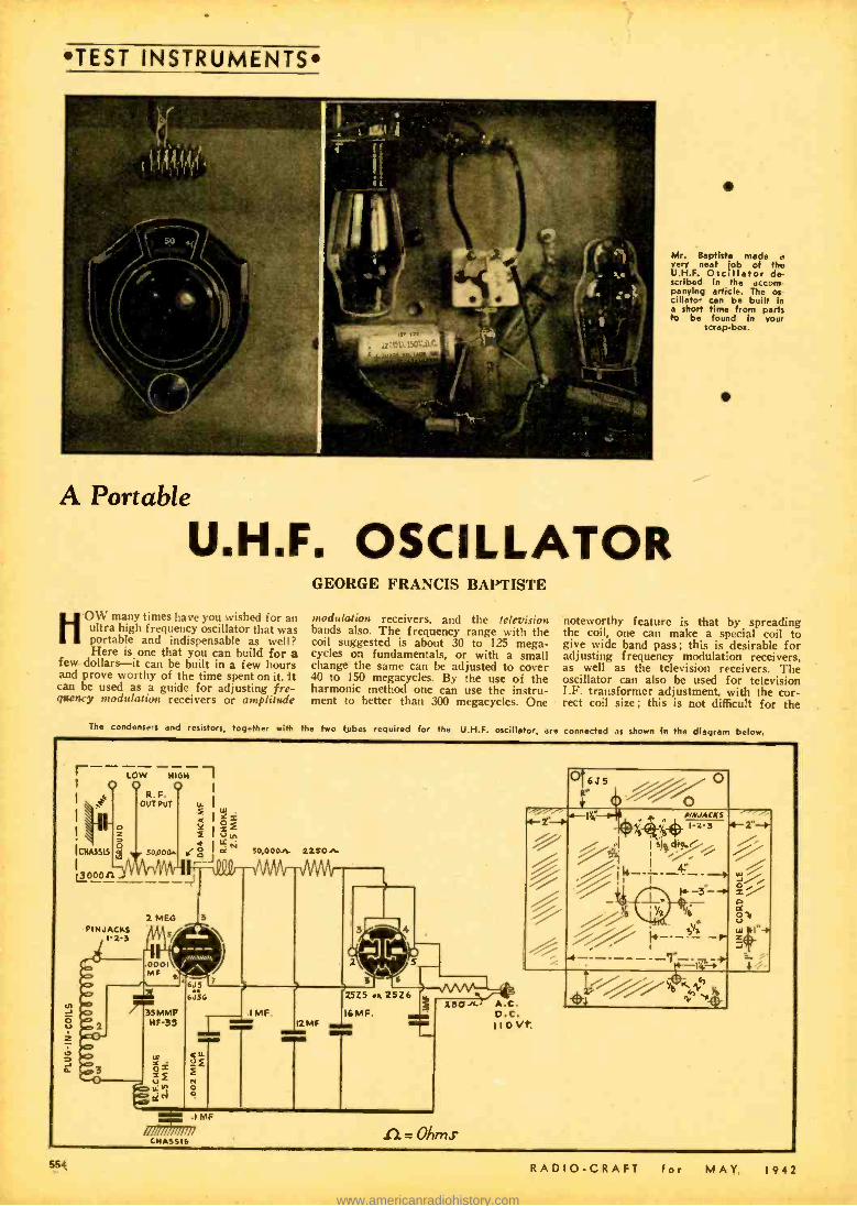
TEST INSTRUMENTS
Mr. Baptiste made a very neat job of th. U.H.F. Oscillator de- scribed In the accom- panying article. The os- cillator can be built in a short time from parts to be found in your
swap -bos.
A Portable
U.H.F. OSCILLATOR UOW many times have you wished for an
ultra high frequency oscillator that was portable and indispensable as well? Here is one that you can build for a
few dollars -it can be built in a few hours and prove worthy of the time spent on it. it can be used as a guide for adjusting fre- gaency modulation receivers or amplitude
GEORGE FRANCIS BAPTISTE
modulation receivers, and the television bands also. The frequency range with the coil suggested is about 30 to 125 mega- cycles on fundamentals, or with a small change the same can be adjusted to cover 40 to 150 megacycles. By the use of the harmonic method one can use the instru- ment to better than 300 megacycles. One
noteworthy feature is that by spreading the coil, one can make a special coil to give wide band pass; this is desirable for adjusting frequency modulation receivers, as well as the television receivers. The oscillator can also be used for television I.F. transformer adjustment, with the cor- rect coil size; this is not difficult for the
The condensers and resistors, together with the two tubes required for the U.H.F. oscillator, are connected as shown in the diagram below.
r LOW NIGH I
I j
I 00 OUT R. F.
\ u l
4 jO1 = s 13,,,
+ LL Ñ lL1U3313 ag s0poa. IC Oo oè 50,000+ 215on.
2 MEG pINJACKS
I'2-3
2e0 A.C. D.C. 110Vt
.1 MF
J /11111 /I /I /II CHASSIS n = Ohms
C16J5
-r
; j/ /" tiy~
554 RADIO -CRAFT for MAY. 1942
www.americanradiohistory.com
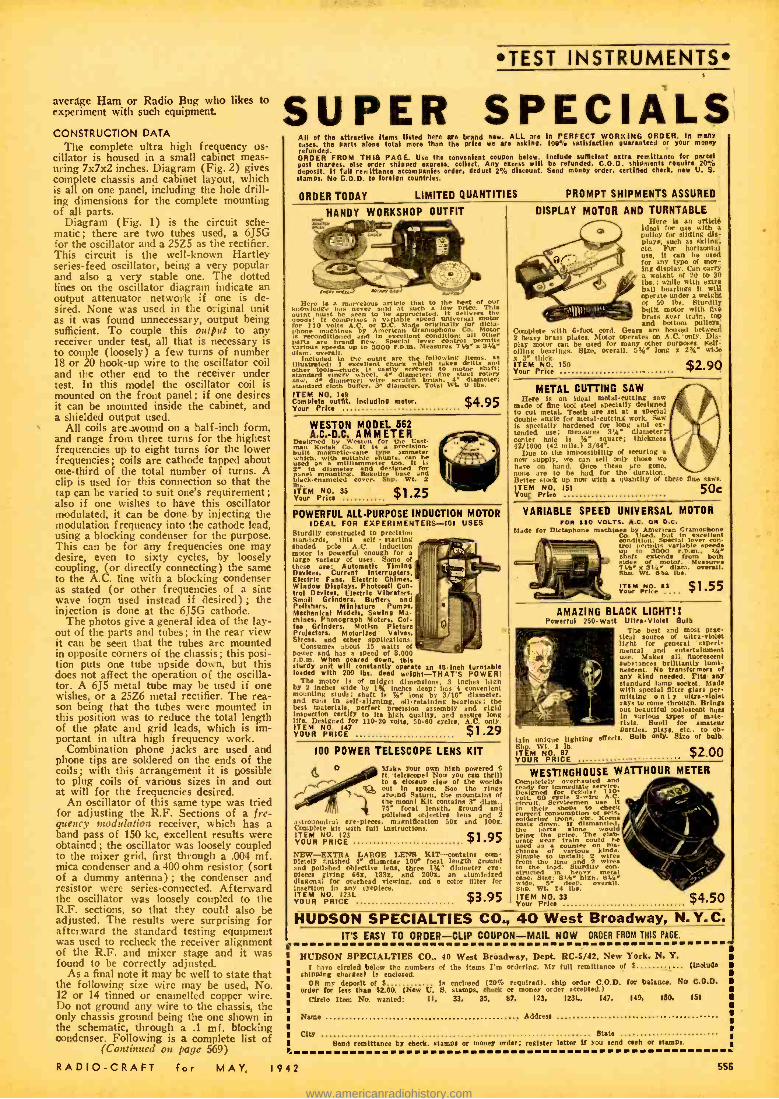
average Ham or Radio Bug who likes to experiment with such equipment
CONSTRUCTION DATA
The complete ultra high frequency os- cillator is housed in a small cabinet meas- uring 7x7x2 inches. Diagram (Fig. 2) gives complete chassis and cabinet layout, which is all on one panel, including the hole drill- ing dimensions for the complete mounting of all parts.
Diagram (Fig. 1) is the circuit sche- matic; there are two tubes used, a 6J5G for the oscillator and a 25Z5 as the rectifier. This circuit is the well -known Hartley series -feed oscillator, being a very popular and also a very stable one. The dotted lines on the oscillator diagram indicate an output attenuator network if one is de- sired. None was used in the original unit as it was found unnecessary, output being sufficient. To couple this output to any receiver under test, all that is necessary is to couple (loosely) a few turns of number 18 or 20 hook -up wire to the oscillator coil and the other end to the receiver under test. In this model the oscillator coil is mounted on the front panel; if one desires it can be mounted inside the cabinet, and a shielded output used.
All coils are wound on a half -inch form, and range from three turns for the highest frequencies up to eight turns for the lower frequencies; coils are cathode tapped about one -third of the total number of turns. A clip is used for this connection so that the tap can be varied to suit one's requirement; also if one wishes to have this oscillator modulated, it can be done by injecting the modulation frequency into the cathode lead, using a blocking condenser for the purpose. This can be for any frequencies one may desire, even to sixty cycles, by loosely coupling, (or directly connecting) the same to the A.C. line with a blocking condenser as stated (or other frequencies of a sine wave form used instead if desired) ; the injection is done at the 6J5G cathode.
The photos give a general idea of the lay- out of the parts and tubes; in the rear view it can be seen that the tubes are mounted in opposite corners of the chassis ; this posi- tion puts one tube upside down, but this does not affect the operation of the oscilla- tor. A 6J5 metal tube may be used if one wishes, or a 25Z6 metal rectifier. The rea- son being that the tubes were mounted in this position was to reduce the total length of the plate and grid leads, which is im- portant in ultra high frequency work.
Combination phone jacks are used and phone tips are soldered on the ends of the coils; with this arrangement it is possible to plug coils of various sizes in and out at will for the frequencies desired.
An oscillator of this same type was tried for adjusting the R.F. Sections of a fre- quency nwdulation receiver, which has a band pass of 150 kc, excellent results were obtained; the oscillator was loosely coupled to the mixer grid, first through a .004 mf. mica condenser and a 400 ohm resistor (sort of a dummy antenna) ; the condenser and resistor were series- connected. Afterward the oscillator was loosely coupled to the R.F. sections, so that they could also be adjusted. The results were surprising for afterward the standard testing equipment was used to recheck the receiver alignment of the R.F. and mixer stage and it was found to be correctly adjusted.
As a final note it may be well to state that the following size wire may be used, No. 12 or 14 tinned or enamelled copper wire. Do not ground any wire to the chassis, the only chassis ground being the one shown in the schematic, through a .1 mf. blocking condenser. Following is a complete list of
(Continued on page 569)
RADIO -CRAFT for MAY, 1942
TEST INSTRUMENTS
SUPER SPECIALS All of the attractive Items listed here are brand new. ALL are In PERFECT WORKING ORDER. In many cases, the parts alone total more than the price we are asking. 100% satisfaction guaranteed or your money refunded. ORDER FROM THIS PAGE. Use the convenient coupon below. Include sufficient extra remittance for parcel post charges, deposit. f full
else order deduct o2% discount. Send money order.
C.O.D. ertified check news
/.
stamps. No C.O.D. to foreign countries. S
ORDER TODAY LIMITED QUANTITIES
HANDY WORKSHOP OUTFIT
Here ria` -von marvelous article that to the hest Of our knowledge has never ld at such low price. This outfit t m
seen to be reciated. It dlivers the
for 4110 It comprises
AC.so D.C. a Maiden originally for dicta.
reconditioned by
or leGramophone condition: ill Motor
e
varins sen It7 permits various speeds to 3000 r.p.m.Measures 4' VC diem. overall.
Included in the outfit the following Items. as Illustrated: 1 excellent chuck which takes drills and other tools -chuck i. easily screwed to motor shaft; standard emery heel 4- diameter: One steel rotary
4. diameter ire scratch h h. dia ter. Standard cloth buffer. 3' diameter. Total Wt. 9 lbs. ITEM NO. 149 Complete outfit. including motor. $4.95 Your Prite
WESTON MODEL 562 A.C. -D.0 AMMETER
Designed by Weston for the East.
built Kodak It
e It le pacmeter which.
magnetic-vane imitable shunts.
t'e
used n simam d t gn'it 2.
in diameter desied for panel Bakelite black-enameled cover. tbs. ITEM N0. 35 $1.25 Your Price
POWERFUL ALL -PURPOSE INDUCTION MOTOR IDEAL FOR EXPERIMENTERS -101 USES
Sturdily constructed to precision standards, this eel( - starting shaded pole A.C. Induction
motor le powerful enough for a
large variety of uses. Some of these are: Automatic Timing Devices, Current Interrupters, Electric Fans, Electric Chimes. Window Displays, Photocell Con- trol Devices, Electric Vibrators, Smell Grinders. Buffers and Polishers, Miniature Pumps, Mechanical Models. Sewing Ma- chines. Phonograph Motors. Cot. fee Grinders. Motion Picture Projectors, Motorized Valves. Sirens, and ether applications.
Consumes about 15 watts of poser and lias a speed of 3,000 r.p. m. When geared down. this sturdy unit will constantly operate an 18 Inch turntable loaded with 200 lbs. dead weight- THAT'S POWER:
The motor fe of midget dimensions. 3 Inches high by 2 Inchon wide by I% inches deep: has 4 convenient mounting studs: shaft Is i4 long by 3/16' diameter, and runs in Belt- tlgning, otlretaininf bearing.; the best material.. perfect precision assembly and rigid Inspection certify to its high quality, and sauce long life. Designed for 110.20 volts, 50.80 cycles, A.C. only. ITEM NO. YOUR PRICE? $1.29
PROMPT SHIPMENTS ASSURED
DISPLAY MOTOR AND TURNTABLE Here is an article
ideal for with a pulley for eliding dis- play., such as skiing, etc. For horizontal use. it can be used for any type of mm.- Ing display. Can arry a weight of 20 to 30 lbs.; While with extra ball bearings it will operate under a weight of 50 she. Sturdily built motor with live braes gear train. top and bottom pulleys.
Complete with 6 -foot cord. Gears are housed between 2 heavy brass plates. Motor operate. on A.C. only. Dis- play motor can be used for many other purposes. Self - oiling bearings. Size, overall, 5t' long a 24 wide x :C thick. ITEM NO. 150 ,$2 90 Your Price
METAL CUTTING SAW Here is an ideal metal -cutting saw
made of tine tool steel specially deelgned to cut meaL 'Teeth are set at a special double angle for metal- cutting work. Saw is specially hardened for long Mid ex- tended use; measures 3m. diameter; center hole is Yee square; thickness 42/1000 (42 mils.) 3/114'.
Due to the impossibility of securing a
re' supply, no can sell only those we have on hand. Once these are gone, none are to be had for the duration. Metter stet up now with a quantity of these One saws.
50c ITEM NO. 151 Your Price
VARIABLE SPEED UNIVERSAL MOTOR FOR 110 VOLTS. A.C. ON D.C.
Made for Dictaphone machin by American Gramophoe
condition. Special lever con- trol up
permit. variable Spee shaft
to nndd .from both
isides f motor. Measures
s vy'1 of diem. overall.
Oho. Wt. Olt. lbs.
M' F"r°g: a.1- . . $1.55
AMAZING BLACK LIGHT!! Powerful 250 -Watt Ultra -Violet Bulb
The best and most prac- tical source of ult- violet light for general aped- Mental and entertainment use. Makes all fluorescent substances brilliantly lumi- nescent. No transformen of any kind needed. Fits any standard lamp socket. Made with special filter glass per- mitting o n l y ultra-violet rays to Come through. Bring. out beautiful opalescent hues in various type of mate- rils. Swell for amateur partiel. play,, etc., to ob-
tain unique lighting effect.. Bulb only. Size of bulb. STE. tels 1 $2.00 ITEM N0. C7 YOUR PRICE
WESTINGHOUSE WATTHOUR METER Completely overhauled and really for immediate ee ire. Dolt. 00 faele Z wirre A.0 volt.
Servicemen u e it in their shops to
use check
soldering irons consumption fKd-cna
costs down. If di.mantied. the arts alone would brine the price. The elan- orate Bear train
ould he
chines of counter
lous on
Simple to Install: 2 Wins from the line d 2 wires to the load. Studill - structed In heavy Metal case. Sise: 91 high. B V aide. a deep. overall.
Shp. Wt. 14 lbs. ITEM NO. 33 $4.50 Your Price
100 POWER TELESCOPE LENS KIT
a1 O Stake your own high powered 6 lY ft. telescope! Now you ran thrill
tO a clomp view of the worlds out In space. See the rings
ound Saturn. the mountains of the mean! Kit contains 3' diem., 75' focal length, ground and polished objective lets and 2
a.trobanicsi eye -pieta. magnification 50x and 1001. Complete kit with full Instructions. ITEM NO. 123 YOUR PRICE $1.95 NEW -EXTRA LARGE LENS HIT- contains cons- Motel, finished 4e diameter 100e foal length ground and pouched objective lens, three 1t4' diameter eye- pieces tiring 68x, 1331, and 2001. an aluminized diagonal for overhead viewing, and color filter for Insertion In any eyepiece. ITEM NO. I23L $3.95 YOUR PRICE `P
HUDSON SPECIALTIES CO., 40 West Broadway, N.Y.C. IT'S EASY TO ORDER -CLIP COUPON -MAIL NOW ORDER FROM THIS PAGE.
HUDSON SPECIALTIES CO., 40 West Broadway, Dept. RC -5/42, New York, N. Y. i have circled below the numbers of the items I'm ordering. My full remittance of S (UMW*
shinsng charges) is enclosed. OR my deposit of S to cnetoeed (20% required). ship order C.O.D. for balance. No C.O.O.
Order tar less than 5200. (New V. S. stamps. check or money order accepted.) Circle Ilam No. wanted: II, 33, 35. 87, 123, I23L, 147.
Nam. Addreu
149, 130,
City State Bend remittance by check. tamps or money order; register letter if YOU send each Of tamps
151
556
www.americanradiohistory.com

TEST INSTRUMENTS*
R1 d
RZ
R 3S 3
f'
R4
t4
R7 ti 1 RjOr
i VR-90
C21 _1 I
Ì C31 1 II----.
Sw 2 T9Q0 J
110 V. 1000000'
A. C. Diagram for the simple D.C. vacuum -tube voltmeter.
THE voltmeter described in this article is for .use on direct current only. It is a zero -center meter with four ranges: 5 -0-5, 25 -0 -25, 100 -0 -100, and 500-0-500
volts. The input resistance on all ranges is ten megohms. This is high enough to reduce the error when reading voltage through high- resistance circuits to a mini- mum, and yet is low enough so that little troulle will be experienced with grid cur- rent and false readings as a result.
There are three controls on the front panel: the zero adjust, the range switch, and the on -off switch. No attempt has been made to describe the chassis layout, cabinet, etc., as every serviceman has his own ideas on the subject. The only important thing in regard to the wiring is to use a good grade of hook -up wire and keep the wires from the input, including the switch, well away from the wires carrying current, as leakage will show up readily.
The accuracy of the meter depends on the accuracy of resistors Rl, R2, R3, and R4. These should be precision resistors, but these are difficult to obtain here, so I used carbon resistors of the next lower value and filed them down until they were cor- rect.
After the instrument is assembled and wired it must be calibrated. This is done as follows: Adjust bias resistor R5 to approximately 7500 ohms. Set Zero Adjust at extreme counter -clockwise position. Set
Range Switch on 5 -0-5 scale. Turn instru- ment on'and allow to warm up. Then set Zero Adjust so meter reads .5 ma. or zero volts. Apply 5 volts D.C. to the input; positive lead going to the ungrounded ter- minal. The meter should read exactly 1 ma. or 5 volts. If it reads under, turn off power and reduce the value of R5 slightly. Then turn on, allow to warm up, reset Zero Ad-
' just at zero, and apply 5 volts to the input as above. If the reading is high instead of low, increase the value of R5. Always be sure to reset Zero Adjust after chang- ing RS and before applying the voltage to be checked. Repeat the above adjust- ments until the meter reads zero volts with no voltage applied, and five volts with five volts applied.
The scale from zero to plus five volts is linear, but the scale from zero to nega- tive five volts is not. After it is calibrated on the positive side, it is suggested that negative voltages from one -half to five volts in one -half volt steps be applied and the readings either be drawn on the meter scale directly, or a chart made showing readings plotted against voltage. Do not change bias resistor after it has been cali- brated on positive voltage. If the calibra- tion is carefully made on the 5 -0-5 volt scale, it will be accurate on the other ranges.
While a type 76 tube was used in the writer's instrument, a type 37 may be used,
A D.C. Vacuum
Tube
Voltmeter HARRY S. BIXBY
The radio experimenter as well as the "junior" service- man will find this instrument very satisfactory for a great many measurements, and its original cost is extremely low.
or a 27 or 56 may be utilized if the trans- former has a two and one -half volt sec- ondary. In this case probably an 80 would be used as a rectifier.
No voltage control was used, as the line voltage in this section is reasonably steady. However, if one is desired, change the value of R9 to 20,000 ohms and connect a VR -90 as shown by the dotted lines in the schematic.
Will be more than pleased to answer any questions about either the operation or Construction of the instrument, if a stamped addressed envelope is enclosed.
LIST OF PARTS
CONDENSERS One 600 volt, .02 mf. Cl; One 450 volt, 8 mf., C2; One 600 volt, .1 mf., C3.
RESISTORS One 8 megohms, Rl One 1.5 megohms R2; One .4 megohm. R3; One .1 megohm, R4; One 10.000 ohm adjustable R5; One 500,000 ohm 1 watt, 'R6; One 10,000 ohm pot., R7; One 10.000 ohm 1 watt, RS; One 5,000 ohm 10 watt, R9; One 10,000 ohm 10 watt, R10.
MISCELLANEOUS One range switch (1 5.0.5 2, 25.0.25; 3.
100.0 -100; 4, 500.0.300) SWl; One AC Switch, SW2; One Power Transformer, 6.3 & 700 Vt., c.t., T.
(If VR 0 is watt.) d change resistor R9 to 20,000
ohms, 1
You'll Never Guess This Use for "Pick -ups "I An American radio manufacturer was
recently puzzled when the Du Pont com- pany gave it orders, with a high Govern- ment priority, for numbers of sensitive phonograph pickups. Astatic Microphone was still more surprised to find out that Du Pont engineers were putting the phono- graph needles not on phonograph records but against factory fences, relaying the 666
wires' vibrations to amplifiers. So Astatic's engineers redesigned their pickups to make them more compact and weatherproof. Du Pont last fortnight announced the result: fences (equipped with five pickups to the mile) which can catch a wren's song or the sighing wind, and relay the sounds to a watchman five miles away. These pasto- ral effects, however, are usually filtered
out; what the pickups are after are such contact noises as climbing, tunneling, wire - snipping and other signs of sabotage and trespass. Result: as good a watch in fog, blackout, darkness and storm as could be maintained by guards standing elbow to elbow. -TIME Magazine.
If you know of similar new and interest- ing applications, tell the editors.
RADIO -CRAFT for MAY, 1942
www.americanradiohistory.com

SIMPLIFIED "FM" RECEIVER ALIGNMENT
L. M. DEZETTEL
F M
With "FM" receivers in the hands of many thousands of listen- ers, it is important for the radio Serviceman to understand how to align these new type receivers. We asked Mr. Dexettel, an engineer of wide experience, to tell our readers in simple lan- guage how they can proceed to align an average "FM" set. He has prepared the accompanying simplified treatment of the
subject for you.
I -FM alignment can be done with but a V -O -M and the station carrier. 2 -Small FM adapters, because of their low price, will find their way in great numbers to the serviceman. 3 -Home construction kits are
recommended for the serviceman who wants to learn the fundamentals of FM.
SERVICEMEN who do nt pssess a million dollars' worth of equipment can still service FM receivers effec- tively. A good substitute for an FM
signal generator is the FM carrier signal from your local FM station. The only equipment required is a 1000 ohm per volt voltmeter and a good alignment screwdriver containing a minimum of metal. A screw- driver made of polystyrene is best. It is important in the alignment of the sec- ondary of the discriminator because this trimmer is not grounded on either side.
Before we tell you about this method of FM receiver alignment, it is necessary to stress the point that a good basic funda- mental knowledge of the theory of FM receiver operation is essential. Those of you who are not fully acquainted with the theory behind an FM signal should go over other articles in this and past issues of Radio- Craft. The reasonableness of this simplified method of alignment is clear when you know your theory.
Notice that we use the word "alignment" instead of the word "service." The words are somewhat synonymous. Complete serv- icing includes tracing down open or shorted condensers, open resistors, unwanted oscil- lation, etc., plus alignment. Everything but the alignment is done in the usual manner the same as for AM receivers. FM receiv- ers differ from AM receivers only in the manner of alignment.
No intent is meant here to discredit alignment methods using FM modulated signal generators and cathode ray oscillo- scopes. That method is to be preferred if you have the equipment or can afford to buy it. The use of an oscilloscope with an FM signal generator permits you to obtain
a picture of what is going on during the alignment. You can actually see the shape of the I.F. band -width curve and what takes place in the discriminator stage as you adjust it. As desirable as this type of equipment is, and we endorse the purchase of it if you can afford it, it is not essential for the alignment of an FM receiver.
THE FIRST STEP
Now let's get back to our simplified method of alignment. Tune the FM receiver to any one of the FM stations that is on the air and allow the set to warm up for at least 15 minutes. Set your V -O-M on the 100 volt scale or higher, take a poly- styrene alignment tool in your hand, and you're all set to go.
A simple "doublet" antenna of the dimensions shown in the sketch, will help to bring in "FM"
stations more efficiently.
RADIO -CRAFT for ;MAY, 1942
Locate the limiter load resistor. It may be a single resistor or a series of resistors or a resistor and R.F. sensitivity control potentiometer. At any rate, it will be con- nected between the ground return connec- tion of the secondary of the third I.F. transformer and the chassis. Connect your voltmeter between that point of the third I.F. transformer and the chassis -the neg- ative terminal to the I.F. transformer and the positive terminal to chassis. Tune the receiver so that maximum signal strength as indicated on the voltmeter is obtained froni the FM transmitter. From this point on, the tuning dial must not be touched.
Adjust the trimmers of the first three I.F. transformers for maximum reading on the voltmeter. This is done in exactly the ,ime manner as when aligning an AM receiver.
SECOND STEP
Look for the two discriminator load re- sistors. You will find two resistors, usually of 100,000 ohms each, connected in series between either the two cathodes of the discriminator tube, or between one of the cathodes of the tube and ground. Transfer the negative terminal of your voltmeter to the mid -point between the two discrim- inator load resistors. Adjust the primary trimmer of the discriminator transformer for maximum reading on your voltmeter. Now transfer the negative lead of the volt- meter to the "hot" cathode (not the one that is grounded) of the discriminator tube. Adjust the secondary of the discrim- inator for Zero reading on the voltmeter. When we say "adjust for Zero reading on the voltmeter," we mean just that -and not a minus reading.
557
www.americanradiohistory.com
FM
for your- COMMUNICATIONS RECEIVER
TRANSMITTER TEST EQUIPMENT METERS PARTS, ETC. $
Send us a complete description of your equipment. Mention make, model, age. condition. "improvements." etc. If you
$ have an approximate price in mind, state it. We will make a fair cash offer by $ return mall.
$ Hit 'em TWO ways- $
1 -Put your idle apparatus to work, $ for Victory I
2 -Buy Victory Bonds with the cash we give you I
$ $
Sand in your list today! $
HARRISON RCU1O 12 WEST BROADWAY - NEW YORK CITY
LEARN CODE the way you'll be using it
by SOUND The best way to learn to read code is by listening to code. The best way to learn to send code is by hearing your own sending repeated back to you. With the new All -Electric Mas-
ter Teleplex Code Teaching Machine, you learn code the natural, easy, fascinating way. Only instrument ever produced which records your sending in visible dots and dashes -then SENDS BACK your own key work at any speed you de- sire. There are NO PERFORATIONS -NO INK. Far superior to anything ever developed . . . a marvel of simplicity. That's why practically every school teaching code wee TELEPLEX. We fur- nish complete course, lend you All- Electric Master Teleplex, give you personal instruction with a MONEY BACK GUARANTEE-all at s surpris- ingly low cost per month. Write today for FREE catalog S6. No obligation.
TELEPLEX CO. JERSEY CITY, N J.
41.C. t°ga:s I'LL FINANCE YOUR TRAINING Mail the Coupon TODAY and I'll not only tell you about my quick, easy way to train for a good pay
Blob in Radio, Television and Sound. UT. I'll also tell
l!you how you can
get it monthlydpayments starring OÚ days of ter 8 weeks' training DettoU
LEARN BY DOING On Real Equipment in Coyne Shops Simple, sy method of Practical Training ?You don't need previ- ous 1 learning.
experience oo You work n lot of book l
Chnt in the Coyne Shops at icago. This 8 weeks training pre-
pares you for a job in service and repair work -we also offer radio orating training. Full details of the training will also be Bent you when you send coupon.
QUICK, EASY WAY TO TRAIN FOR
RADIO in ó WEEKS
EARN WHILE LEARNING, lob Kelp Afte r Graduation We you e.aft living t n.d th give y u Im arieg groan. ei see
H. C. LEWIS, President, Radio Division, Coyne Electrical School 500 S. Pauline St., Dept. 82 -SII, Chicago, ill. Dear Mr. Lewis:
Please send me your Big FREE Book and details A of your PAY -AFTER- GRADUATION -!'LAN.
NAME ADDRESS CITY STATE
558
Connect the negative terminal of your voltmeter to the mid -point on the two re- sistors again and touch up the primary trimmer on the discriminator transformer for maximum reading again. Go back again to a little touching up of the secondary trimmer by the method described above. Each time that one side of a transformer is adjusted, there is a slight change effec- tive on the opposite side, and it is necessary to go back and forth once or twice until no further change occurs.
Let us stress the point again regarding the Zero reading on the voltmeter when the secondary of the discriminator trans- former is adjusted. Before you even begin your work the needle on your voltmeter should be set so that it falls exactly on the Zero line when no voltage is applied. When the Zero adjustment mentioned above is made, the needle should fall on the Zero line and not a hair above or below that line.
THIRD STEP
Alignment of the high frequency an- tenna, R.F. and oscillator circuits is done in the same manner as for AM receivers. That is all there is to the alignment. Checking the accuracy of your work is a simple matter. With the voltmeter con- nected between the mid -point of the two discriminator load resistors and chassis, tune the FM receiver a few kilocycles above and below its original setting. In one di- rection the voltmeter will read higher than before and in the other direction, the volt- meter will read lower. The amount higher and lower than the original voltmeter read- ing should be equal for equal frequency deviations from the original setting of the receiver.
Here is another check. Connect the volt- meter across the entire discriminator load resistor as when adjusting the secondary of the discriminator transformer. Now, when the receiver is tuned above and below the station frequency, the voltmeter should read an equal amount plus and minus from the Zero point. To obtain the reading below the Zero point, it will be necessary for you to reverse the leads from the voltmeter. It will then read above the Zero point but the polarity has been reversed.
Do not worry too much about the extra loading effect of the voltmeter in the dis- criminator circuit. It is true that the re- sistance of the meter in parallel with the discriminator load resistors will upset their values somewhat. Fortunately, this change in resistor values does not affect the per- formance of the FM receiver very much. The ear cannot detect the difference in quality from a received signal, whether the voltmeter is connected in the circuit or not.
It is obvious that a more perfect job can be done if the voltmeter has no loading effect on the circuit. If you are the for- tunate possessor of an electronic voltmeter or one of the vacuum tube types, so much the better. As we said before, the ear can't tell the difference.
The adjustment of the discriminator transformer is the most important part of the entire receiver alignment procedure. If this transformer is not tuned properly, musical distortion will result and the back- ground noise level will be higher. If you get a call that an FM receiver is not pro- ducing perfectly clear tones, but is dis- torting, you can bet that the answer in most cases is in the adjustment of dis- criminator transformer.
Noise reduction takes place in two stages of the FM receiver -the limiter stage and the discriminator stage. Proper peaking of the I.F. channel for the pur-
pose of producing as strong a carrier sig- nal to the limiter stage is important for the reduction of noise. Proper alignment of the discriminator stage allows only the frequency modulated signal to be de -modu- lated into its audio component. Since static, natural or man -made, is mostly amplitude modulated, what little gets to the discriminator stage from the limiter is stopped there if the discriminator trans- former is properly aligned.
So you see, that the most important rt of servicing FM receivers is in the align- ment. With a little intelligence, however, you can do a good job with but simple equipment.
GOOD ANTENNA VERY IMPORTANT We mention that the limiter stage should
receive as strong a signal as possible. An- other method by which this is accomplished is the use of a good antenna. While fair performance can be obtained from any kind of a piece of wire used as an antenna, one that is designed for the FM band will give much better results. We are emphatic about the word "much." Don't hesitate to stress the importance of a good antenna to your customer: The installation of the right type of antenna will not only mean more profit to you but will bring your customer amazingly better reception. You can easily build an FM antenna for your customer by following the dimensions shown in the sketch. This antenna is known as a simple doublet or di -pole antenna, familiar to the amateurs who have operated on the ultra high frequency bands. The center insulator should be one of about a 2 or 3 inch length and the triangle formed by the "Y" connection of the feeders should have equal dimensions on the three sides. While any twisted line may be used as lead -in, the better the quality of this lead -in, the better the results. In fact, if a low quality lead -in is used and its length is very great, a point is reached where the losses in the lead -in exceed the benefits of a good antenna. The important point to consider in the quality of lead -in wire is the type of insulation used. Buy the best that your customer can afford.
The ideal lead -in for an FM antenna is a co -axial cable made of copper tubing and ceramic beads for supporting the inner conductor. The next best thing is the flex- ible type co-axial cable, such as is made by Amphenol, using polystyrene beads.
If all -wave reception is required, you will fare better by purchasing one of the commercially made combination antennas. There are several on the market today. These antennas are cut to a certain length which, with their specially designed trans- formers, give good efficiency on several bands. Antennas of this type cannot be highly efficient on any one band but are effective compromises where all -band op- eration is required. We have in mind an excellent antenna of this type made by Taco. This antenna is designed for great- est efficiency on the FM band, where it is needed most.
It is important that the antenna he in- stalled as high as possible and clear of all surrounding buildings or other obstacles. The top element of the antenna must be horizontal as horizontal polarization is now the standard method of FM transmission. The antenna should be installed so that its axis is perpendicular to the line of transmission from the FM broadcast sta- tion (i. e., the doublet aerial should be placed broadside to the transmitter).
This article prepared from data supplied by courtesy of the Allied Radio Corp. Mr. Dezettel is an engineer with that company.
RADIO -CRAFT for MAY, 1942
www.americanradiohistory.com
INDUSTRY ANSWERS THE CALL!
QltgwsgtGEg`$ s ti o .- EY.ÿ L. ILA
'°`° ,°-.,°''-~; . ur ;,..rvw;.. `
/..* As.d rP.J' ° yyrV 0 `,,.+,.. °s;°`" ME "' ",,r 4:-.:,....,.#.5''',:+1,,,,..,:..,..e.,., + t ..e.s w ...r
.... +`'.. .a,,,0 ¡`. .17,...:::.
N ° ,p.°" 1::°,..1.:* i d Y- ..^1S r ,n ÿ..ÿ?,..i.y. v°° y ,! .+ yM"'"je r ..,,.M,.,A r'0 t . ' ,;. ÿ.. too-
e.. ::::%:....,1-,........::-,,,?:. r+
t. t .+°°;., . , ..,,'.a,.í. ̀ "- "*'':: "%°°ó.. ,".-.ö.. .) lr SOf pv""Sy..H4 f 0 r.r®.1p 4
32,145 Firms With Over 17,700,000 Employees Have Installed the a . .
PAY -ROLL SAVINGS PLAN *
-AM *
-AM
*
Have YOU Started the Pay- Roll
Savings Plan in YOUR Company? Like a strong, healthy wind, the Pay -Roll Savings
Plan is sweeping America! Already more than 32,000 firms, large and small, have adopted the Plan, with a total of over seventeen million employees - and the number is swelling hourly.
But time is short! ..More and more billions are needed, and needed fast, to help buy the guns, tanks, planes, and ships America's fighting forces must have. The best and quickest way to raise this money is by giving every American wage earner a chance to participate in the regular, systematic purchase of Defense Bonds. The Plan provides the one perfect means of sluicing a part of ALL America's income into the Defense Bond channel regularly every pay- day in an ever -rising flood.
Do your part by installing the Pay -Roll Savings Plan now. For truly, in this war, this people's war, VICTORY BEGINS AT THE PAY WINDOW.
Plan Easy to Install
*
Like all efficient systems, the Pay -Roll Savings Plan is amazingly easy to install, whether your employees number three or ten thousand.
For full facts and samples of free literature, send the coupon below -today! Or write, Treasury De- partment, Section C, 709 Twelfth Street NW., Washington, D. C.
MAIL TITI Treasury S W
eut, Section C
l2 h C. putt. ?lease 109-12th
Washington, D.
out ,atns °want ü t e6 plao- h° ray-Bell . .
co P
U. S. Defense BONDS * STAMPS
This since is a Contribution to NATIONAL DEFENSE br Radio -Craft
www.americanradiohistory.com
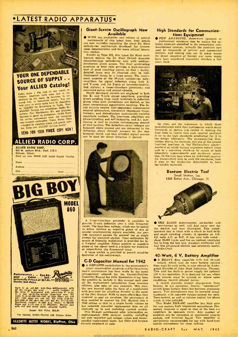
LATEST RADIO APPARATUS
YOUR ONE DEPENDE BLE
SOURCE OF
Your ALLIED Catalog! Radio plays a big part in our march te
Victory. American radio must stay at top
efmctency to the home, in factories' In re
search labs. ln instruction centers. You can
help serve on every radio front by depending
on ALLIED for Everything in Radio. Your
ALLIED Catalog has ererythhse -Radio Re-
ceivers; Test Equipment: PA and Intercom
Systems to speed up production: 19.000 Parts
for service replacement Work, for industrial
and research application: Tubes. Books, Tools
-backed by complete stocka and speedy serv-
ice. Keep year ALLIED Catalog bandit
SEND FOR NOUN FREE CO PN NOW !
City
ALLIED RADIO CORP. 833 W. Jackson Blvd., Dept. 2.E.2 Chispo, Illinois Send me your FREE 1942 Radio Supply Catalog
Name
Address
State
GB!! 1 MOD-EL
860
Performance . . Eye Ap- peal Value . Sen- sationally Priced at 819.65, Dealer Net Price
Here Is an AC -DC Volt- Ohm- Milllammeter with all the ranges you want . . easily readable on the large r instrument with entra-long 6" scale, In a new up- lothe- minute three -tone eue. DC Volts 0- 10.50- 250. 5001000 at 5000 Ohms per volt DC: 1000 ohms oar vols AC. AC Volts 0- 10 -50- 250 -1000 at 400 ohms per volt: DC Ma. 0 -I -10 -100; Resistance ranges; 0 -1500 Low Ohms: 0- 150.000 Ohms and 0 -7.5 and 0 -15 Megnhms. Maroon case with rod and silver panel. attached handle.
Dealer Net Price, 119.65
For Catalog Write Rection 516 College Drive
READRITE METER WORKS, Bluffton, Ohio
Giant- Screen Oscillograph Now Available
WITH the production and release of several instruments of this latest type, final details
are now available regarding the giant Du Mont cathode -ray oecillograph developed for lecture - room demonstration and for more critical labora- tory studies.
Known as Type 288, this latest Du Mont cecil- lograph utilizes the Du Mont 20 -inch diameter intensifier -type cathode -ray tube with medium - persistence green screen. The final accelerating potential of 6000 volts provides a high -intensity spot of good resolving power. so that a highly - detailed trace may be observed even in well - illuminated rooms by a large group. The Instru- ment consists of the 20 -inch cathode -ray tube; amplifiers for signal deflection along both X- and Y -axes, and for Z -axis or intensity- modula- tion signals; a linear -time -base generator; and associated power and control circuits.
Newly developed circuits are employed in both the X- and Y -axis signal amplifiers, providing direct coupling from input terminals to deflection plates when such connections are desired, or the more conventional capacitative coupling. The in- put circuits employ high -impedance compensated stepped attenuators, thermionic impedance trans- formers, and diatortionless continuously- variable amplitude controls. The two -stage amplifiers are phase -inverting and self -balancing. and d.c. posi- tioning is used to provide instantaneous control of spot location. The deflection -signal voltages are balanced above ground and are connected to the deflection plates through jumpers on the rear terminal board, and thus external signal sources can be used for direct deflection if desired.
A linear -time -base generator is available to provide X -axis deflection over a wide frequency range. The time -base voltage, which can be locked to either positive or negative phase of one of several synchronizing signals available, can pro- vide recurrent sweeps for general use or single sweeps for transient studies. Time calibration by means of intensity modulation is provided for by a Z- signal amplifier. Either positive or negative phase of the signal used is available for blanking or intensifying the fluorescent trace.
A beam switch is provided to permit stand -by operation of the oscillograph.
C -D Capacitor Manual for 1942 A DEFINITE contribution to the government's paper conservation program and to the service-
man's convenience has been made by the bowl arrangement adopted for the Cornell -Dubilier Capacitor Manual for 1942 Heretofore it has been the practice to include in this manual each year all the replacement information from previous editions. plus data on new receivers. This year. the new manual takes the form of a supplement with provision for attaching directly to the cover of the 1941 Manual. With no more effort than that required to seal an envelope, the serviceman is thus enabled to convert his 1941 Manual into a 1942 edition so that in a single handy volume he has complete capacitor replacement data on all receivers up to and including current models.
This 60 -page supplement adds information on approximately 2000 receiver models, including not only capacitor and voltage values and recom- mended replacement types, but filter and by -pass circuits employed in each.
High Standards for Communica- tions Equipment
FEW AMATEURS, short-wave listeners or professional operators stop to realize the ex-
treme precision embodied in the present -day com- munications receiver. Actually the receivers now used by thousands of private and commercial stations, and coming into use in many homes for direct reception of foreign war news, would have been considered laboratory wonders a few years back.
So close are the tolerances to which three manufacturers work that instrumenta worth many thousands of dollars are needed in making the final tests to insure that each receiver produced is up to the high standards established for it in the design laboratory. The accompanying illus- tration shows. for example, just one of the several final -teat positions in the Hallicraftera plant - positions at which trained engineers submit every unit to a searching check -up by means of both laboratory measurements and on- the -air opera- tion. In the rare case where an individual receiver (or transmitter) fails to meet the standards, back it goes to the production department to have the trouble corrected.
Bantam Electric Tool Small Motors, inc.
1308 Elston Ave., Chicago, Ill.
THE RADIO experimenter, set -builder and serviceman as well, will find many uses for
the electric tool here illustrated. This motor- operated tool is fitted with a chuck to hold drills and small grinding wheels ; it operates on 110- 116 volts A.C. or D.C. It has very high speed - about 20,000 r.p.m. and has an internal ventilator fan to keep the tool cool. Amateur craftsmen will find this all -around electric tool extremely usefuL -Radio -Craft.
40 -Watt, 6 V. Battery Amplifier A HEAVY duty amplifier with full 40 -watt output, which uses no more battery current .
than most 25 -watt units, is now offered by Audio- graph Division of John Meek Industries, Chicago. This unit has built -in power supply for optional 110 v. a -c operation. It is designed for use where large crowds must be covered or where noise conditions require greater power.
A switch provides instant change -over from battery to a-c operation. Special "economizer" switch keeps battery drain low between announce- ments. Two microphones may be operated simul- taneously, with separate volume control for each. Tone control, as well as volume control for phono input, is also included.
This Model BMA -40C amplifier has high gain for any modern high impedance microphone. Fre- quency response is equal to that of the best a -c amplifiers its sponsors claim. Any number of speakers can be connected at convenient plug -in sockets and terminal board. This amplifier is particularly recommended for use with hand -type mobile microphone for close talking.
.660 RADIO -CRAFT for MAY. 1942
www.americanradiohistory.com
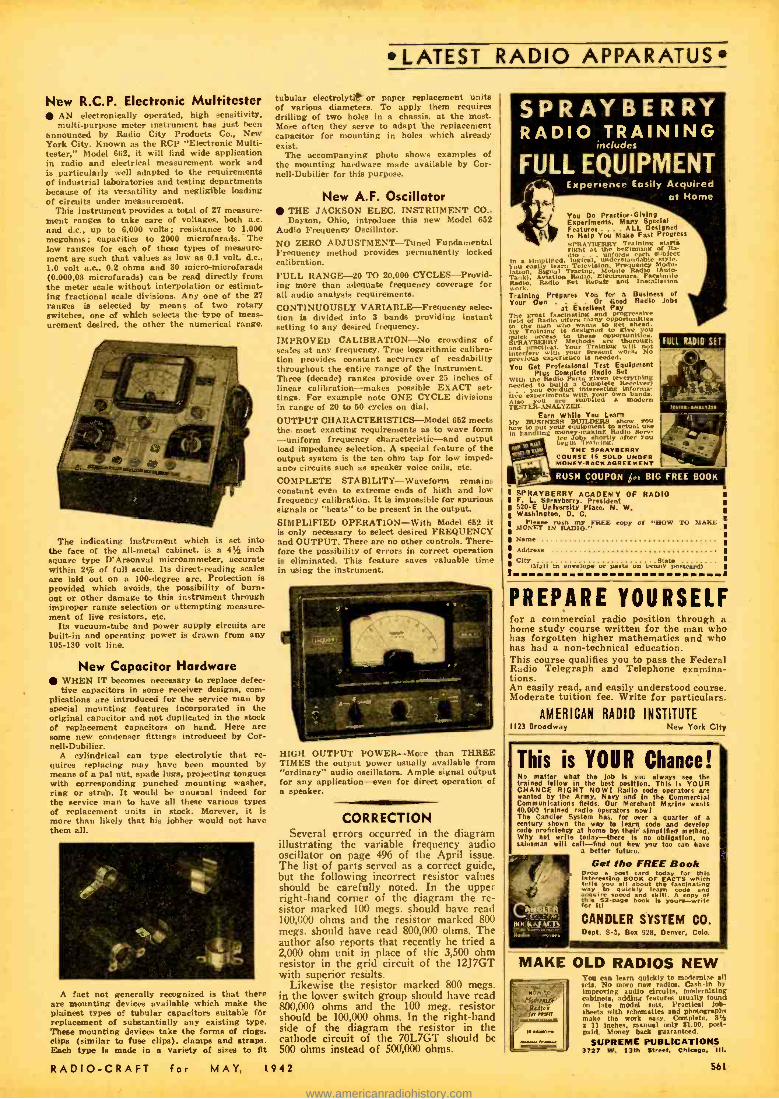
New R.C.P. Electronic Multitester AN electronically operated, high sensitivity, multi -purpose meter instrument has just been
announced by Radio City Products Co., New York City. Known as the RCI' "Electronic Multi - tester," Model 662, it will find wide application in radio and electrical measurement work and is particularly well adapted to the requirements of industrial laboratories and testing departments because of its versatility and negligible loading of circuits under measurement.
This instrument provides a total of 27 measure- ment ranges to take care of voltages, both a.c. and d.c., up to 6,000 volta; resistance to 1,000 megohms; capacities to 2000 microfarads. The low ranges for each of these types of measure- ment are such that values as low as 0.1 volt, d.c., 1.0 volt a.c., 0.2 ohms and 80 micro-microfarads (0.000,03 microfarads) can be read directly from the meter scale without interpolation or estimat- ing fractional scale divisions. Any one of the 27
ranges is selected by means of two rotary switches, one of which selects the type of meas- urement desired, the other the numerical range.
The indicating instrument which is set into the face of the all -metal cabinet, is a 4'j inch square type D'Arsonval microammeter, accurate within 2% of full scale. Its direct- reading scales are laid out on a 100- degree arc. Protection is provided which avoids the possibility of burn- out or other damage to this instrument through improper range selection or attempting measure- ment of live resistors, etc.
Its vacuum -tube and power supply circuits are built -in and operating power is drawn from any 106 -180 volt line.
New Capacitor Hardware WHEN IT becomes necessary to replace defec- tive capacitors in some receiver designs, com-
plications are introduced for the service man by special mounting features incorporated in the original capacitor and not duplicated in the stock of replacement capacitors on hand. Here are some new condenser fittings introduced by Cor- nell- Dubilier.
A cylindrical can type electrolytic that re- quires replacing may have been mounted by means of a pal nut, spade lugs, projecting tongues with corresponding punched mounting washer. ring or strap. It would be unusual indeed for the service man to have all these various types of replacement units in stock. Morever, it is more than likely that his jobber would not have them all.
A fact not generally recognized is that there are mounting devices available which make the plainest types of tubular capacitors suitable Mr replacement of substantially any existing type. These mounting devices take the forms of rings. clips (similar to fuse clips), clamps and straps. Each type is made in a variety of sizes to fit
LATEST RADIO APPARATUS
tubular electrolytic or paper replacement units of various diameters. To apply them requires drilling of two holes in a chassis, at the most. More often they serve to adapt the replacement capacitor for mounting in holes which already exist.
The accompanying photo shows examples of the mounting hardware made available by Cor- nell-Dubilier for this purpose.
New A.F. Oscillator THE JACKSON ELEC. INSTRUMENT CO., Dayton. Ohio, introduce this new Model 652
Audio Frequency Oscillator.
NO ZERO ADJUSTMENT -Tuned Fundamental Frequency method provides permanently locked calibration. FULL RANGE -20 TO 20,000 CYCLES- Provid- ing more than adequate frequency coverage for all audio analysis requirements.
CONTINUOUSLY VARIABLE -Frequency selec- tion is divided into 3 bands providing instant setting to any desired frequency.
IMPROVED CALIBRATION -No crowding of scales at any frequency. True logarithmic calibra- tion provides constant accuracy of readability throughout the entire range of the instrument. Three (decade) ranges provide over 25 inches of linear calibration -makes possible EXACT set- tings. For example note ONE CYCLE divisions in range of 20 to 50 cycles on dial.
OUTPUT CHARACTERISTICS -Model 652 meets the most exacting requirements as to wave form -uniform frequency characteristic-and output load impedance selection. A special feature of the output system is the ten ohm tap for low imped- ance circuits such as speaker voice coils, etc.
COMPLETE STABILITY -Waveform remains constant even to extreme ends of high and low frequency calibration. It is impossible for spurious signals or "beats" to be present in the output.
SIMPLIFIED OPERATION -With Model 652 it is only necessary to select desired FREQUENCY and OUTPUT. There are no other controls. There- fore the possibility of errors in correct operation is eliminated. This feature saves valuable time in using the instrument.
HIGH OUTPUT POWER Mure than THREE TIMES the output power usually available from "ordinary" audio oscillators. Ample signal output for any application -even for direct operation of a speaker.
CORRECTION Several errors occurred in the diagram
illustrating the variable frequency audio oscillator on page 496 of the April issue. The list of parts served as a correct guide. but the following incorrect resistor values should be carefully noted. In the upper right -hand corner of the diagram the re- sistor marked 100 megs. should have read 100,000 ohms and the resistor marked 800 megs. should have read 800,000 ohms. The author also reports that recently he tried a 2,000 ohm unit in place of the 3,500 ohm resistor in the grid circuit of the 12J7GT with superior results.
Likewise the resistor marked 800 megs. in the lower switch group should have read 800,000 ohms and the 100 meg. resistor should be 100,000 ohms. In the right -hand side of the diagram the resistor in the cathode circuit of the 70L7GT should be 500 ohms instead of 500,000 ohms.
RADIO -CRAFT for MAY, 1942
SPRAYBERRY RADIO TRAINING
includes
FULL EQUIPMENT - Experience Easily Acquired
at Home
You Do Praetloe- Giving Experiments. Many Special Features . . ALL Designed to Help You Make Fast Progress
ght aFYf r at beginning of Ra- dio . . . unfolds h euhlccr
In sim laded.
logical, undentand ble style. You easily learn
Tracing. Mobile Radio Modu-
lation, Radio. Radio
SRadio. Repaair aeeInFstal Lion work. Training Prepares You for Business of Your Own . Or Good Radio Jobs
at Excellent Pay The great fascinating and progressive
to the Radio offers many
t n get ahead. 1M1y Training is designed to give 1y
5PRAVBERRY tMethods arre tnhuorough n rertleI. Your Trinm¢ win
No e
interre fere with r naent ork. py boss. experience 1
s needed:
You Get Professional Test Equipment Plus Complete Radio Set
needed to the Radio Parts
a Complete Receeivier) n . you Conduct interesting informa-
tive experiments with your own hands. Also you supplied modern TESTER- ANALYZER.
rare While You tsars My BUSINESS BUILDERS show vnu how to put your equipment iosuse In handling money-making oad!
ice Jobs shortly atter you begin Training.
TNC SPRAYSERRY COURSE IS SOLD LINDER MONEY SACK
SPRAYBERRY ACADEMY OF RADIO F. L Sprayberry, President 520-E University Place, N. W. Washington, D. C.
Please rush my FREE copy Of "HOW TO MONEY IN RADIO." Name
Address
City(stail in envelope or paste ion penny postcard)
MAKE
PREPARE YOURSELF for a commercial radio position through a home study course written for the man who has forgotten higher mathematics and who has had a non -technical education. This course qualifies you to pass the Federal Radio Telegraph and Telephone examina- tions. An easily read, and easily understood course. Moderate tuition fee. Write for particulars.
AMERICAN RADIO INSTITUTE 1123 Broadway York City
This is YOUR Chance! No matter what the lob is you always see the trained fellow in the best position. This is YOUR CHANCE RIGHT NOW! Radio code operators are wanted by the Army. Navy and in the Commercial Communications fields. Our Merchant Marine wants 40.000 trained radio operators now! The Candler System has. for over a quarter of a century shown the way to learn code and develop code proficiency at home by their simplified method. Why not wri a today -there is no obligation, no salesman will call -find out how you too an have
a better future.
Got fko FREE Book Drop a post card today for this interesting BOOK OF FACTS which tells you all bout the fascinating way to quickly learn code and
cq ir] pee book and skill. A copy of
a for it! for
CANDLER SYSTEM CO. Dept. S.5, Box 928, Denver. Colo.
MAKE OLD RADIOS NEW You rin learn quickly to maternt,, all sets. No moro new radios. Cash -in by improving audio circuits. modernising cabinets. adding features usually found on late model sets. Practical lob - sheets with echematiea and photographs make the work easy. Complete, 8% a 11 inches, manual only 81.00. post- paid. Money hack guaranteed.
SUPREME PUBLICATIONS 3727 W. 13th Street, Chiago, Ill.
561
www.americanradiohistory.com
LATEST RADIO APPARATUS
BOOST
LOWEST PRICES... FASTER DELIVERY at
RADOIEX LARGEST STOCK OF
EVERYTHING IN RADIO J
Thousands of progressive Serv- icemen rely on Radolek for their complete requirements of repair materials. Radolek has in stock for prompt delivery replacement parts to repair any radio -every type of tube,trans- former, speaker, condenser, vol- ume control, resistor, auto radio accessory, etc. Everything you need at lowest prices. You get what you want when you want it- Radolek understands service problems -gets your order to you in double -quick time. Buy- ing from Radolek means Greater Value., Better Service and More Profits. The big new Radolek Radio Service Guide is yours FREE for the asking. Send for your copy today!
RADOLEK P.A. SYSTEMS -FOR EVERY REQUIREMENT
Thousands of successful Radolek P.A. installations are proof of quality, superior design and top performance. Complete systems for permanent, portable or mobile use -wide choice of microphones. speakers and related equipment. Radolek P.A. Systems give you more for your money in Perform- ance, Styling, Dependability and Reserve Power. Select the P.A. apparatus you need from Rad- olek's big new FREE catalog.
RADOLEK REPAIR SERVICE Let Radolek ern.:.- I or burned out transiu :ha , ,;,kers, test equipment. etc. Many Il OW r nnot
iow be replaced and therefore repairing
s the only alternative. Trained crafts- men, using precision tools and factory methods, assure perfect jobs equal to
e
Write for prices or better Mill, send in any article to be re- Paired. Iti_VS handed. Ill be handled DromDtlY.
SEND FOR NEW FREE
RADIO SERVICE GUIDE
RADOLEK CO., Dept. C -66
601 W. Randolph St, Chicago, III.
Please send the Elie FREE Radio Service Guide.
Name
Address ....
C7 nxAi.Frt r FAItPIt'EMAN f`; RI)i'Nlh ENG
SAVE AT RADOLEK 562
ELECTRONIC AIR RAID SIREN John Meck Industries, Audiograph Division
1313 W. Randolph St., Chicago, III. A new electronic type "air raid' aireo, de-
signed to give both great volume for alarms ss well as a simple method of crowd control, is announced by Audiograph Division of John Meck Industries, Chicago. Called the "ElectroSiren," this unit makes use of a vacuum -tube tone gen- erator which can either duplicate the rising and falling tone of a mechanical siren, or can be set at any pitch for beet audibility over traffic or manufacturing noises. It can also be used to send code messages to air raid officials by dots and dashes. Special circuit design allows 50% more power than is possible from an ordinary sound system.
A feature of this new unit Is an arrangement so that a microphone can be used for voice announcements over the same system, which takes the place of a public address system. This is important in avoiding confusion and panic in crowded places. A reassuring voice following an air-raid signal may save countless lives.
The electro -siren normally operates from any 110 -volt source, but in the case of current failure can be instantly switched to 6 volt storage bat- tery operation. It can also be used in police are or other vehicles, operating from the car battery.
The largest system can be operated continuously for four hours from a fully charged battery. - Radio-Croft.
COMMUNICATING SYSTEM The Rauland Corp.
4245 No. Knox Ave., Chicago, III. The W -106 Is a flexible and useful communicat-
ing system for office and industrial application. Warehouses, service stations, small factories, wholesale distributors, professional and business offices will find this syetenf to save much time.
This system consists of a Master, or central control unit. the only amplifier in the entire system. Up to five "remote,' or outlying sub- stations can be used. The master or central unit can call and converse with any one of the five remote stations as selected.
A special feature of this system is that the "master" unit can call and "listen -in" or con- verse with all five remote stations at one time. This is done by means of the sixth, or "all" position on the selector switch.- Radio -Craft.
POLYMET CONDENSERS Polymet Condenser Company 699 E. 135 St., Bronx, N. Y.
The Polymet Condenser Company has an- nounced a very complete line of high efficiency condensera of all types which they have developed through 21 years of constant research and im- provement. The Polymet line includes a long list of electrolytic and by -pass condensers. suit- able for replacements in servicing work. A com- plete list of the various types of condensers this company makes. as well'as prices and specifica- tions can be obtained from your local radio dealer. or else by writing direct to the company.
840 Watt Amplifier AN 840 watt rack and panel sound amplifica- tion unit was recently designed and built by
The Rauland Corporation for the new Plum Brook Ordnance plant at Sandusky, Ohio. The equip- ment comprising that particular installation in- cludes 48 high- powered reproducers and over 16 miles of connecting cable.
The central control unit Is capable of sending out all -wave radio programs and phonograph or microphone programs to all of the reproducers and provides audible coverage over an area of more than 80 square miles.
The system is used primarily for instantly locating personnel who might be any point within the limits of the grounds and is instrumental in providing up- to-the- minute broadcasts to all of the employees throughout the plant.
NEW PHONOGRAPH RCA Mfg. Co., Inc.
Camden, N. J. Here's a table -model phonograph with more
than ample volume. It is useful for apartments or
homes where space is at a premium, but it will Lind a place in dormitories, dens. "rumpus rooms." and a score of other locations where music for en- tertainment or dancing is desired. The instrument la designated as Model R-56. Its motor is self - starting, and the on-off switch and volume con- trol is located handily on the top of the cabinet. serving the dual purpose of a tone arm rest. Either 10- or 12 -inch records may be played. Radio -Croft.
LOW- FREQUENCY LINEAR - TIME -BASE GENERATOR
Allen B. DuMont Labs., Inc. 2 Mein Ave., Passaic, N. J.
For those oscillographic studies requiring sweep frequencies as low as one cycle every few seconds. a Low- Frequency Linear-Time-Base Generator is now announced by Allen B. Du- Mont Laboratories, Inc., of Passaic, N. J. Used in conjunction with an oecillograph provided with a long persistence cathode -ray tube, or with photographic recording methods, this no- cessory instrument opens up new fields of inves- tigation of low -frequency transient and recurrent phenomena. Vibration studies stress and strain measurements, low- frequency electrical observa- tion, electrocardiography and electroencephalo- graphy, are all facilitated by this new unit. The frequency range of the instrument corresponds to rotating speeds of 12 to 7600 r.p.m., thus per- mitting the use of an oscillograph for the visual study of certain characteristics of rotating ma- chinery at low and medium speeds. Transient observation is provided for by a single stroke sweep circuit.
The Type 215 Low- Frequency Linear -Time- Base Generator provides a ewedp frequency range of 0.2 to 126 cycles per second. The maximum undistorted output signal is approximately 450 volts peak- to-peak, balanced to ground. The single sweep is initiated either manually or by observed signal. Excellent linearity is assured by a compensating circuit.
Thoroughly portable, the instrument measures 144' high, 8 18/16^ wide, 19%^ deep. and weighs 41 lbs. Steel cabinet, black wrinkle finish. with carrying handle. Etched metal black panel. 115 or 230 V. A.C. r.m.s. 40 -60 cycle. Power consumption, 50 watts. 1 amp. fuse protection. The primary voltage is selected by a switch in the instrument. -Radio -Craft.
SERVICING BY SIGNAL SUBSTITUTION by G. N. Goldberger, Engineering Division. Preci- sion Apparatus Co. This 120 -page book, bound in attractive blue paper covers, contains practical in- formation of interest to radio students and service- men, in particular. Among the sections noted In this valuable book are- instructions and guide for operation of precision laboratory signal- generator (with diagram of the instrument); the audio test signal and how to use it; how to check tuned R.F. receivers with and without A.V.C.; Super- heterodyne receivers; the adjustment of Frequency
receivers, etc. adjustment
closing section deals with the technique of servicing by Signal Sub- stitution, concluding with a chater entitled "Four Point Rapid Receiver Analysis."
THE SCHOOL SOUND SYSTEM by R. R. Lowdermilk. This book. published by The Federal Radio Education Committee, is interesting to all students of radio and sound applications. It dis- cusses such timely and important topics as Recep- tion of Radio Broadcasts for Classroom Listening; Delayed Radio Broadcast Listening; Administra- tive Uses; Broadcasting by Students; Problems of Equipment, Design and Arrangement; Provision for the Use of Transcriptions. 'etc. A valuable section -Part 3 -deals with "Student Broadcast- ing.' Here we find some very good discussion on the matter of student announcements, etc.
RADIO -CRAFT for MAY, 1942
www.americanradiohistory.com
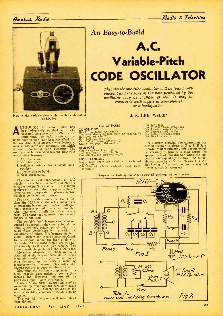
igmataut Nadia Nadia 7alatrieion
Here is the variable -pitch code oscillator described by Mr. Lee.
1AI.THOUGH the radio market has been adequately supplied with A.C. operated code practice oscillators for some time, few A.C. outfits of the
home -built variety have been described for the would -be radio amateur who desires to own an oscillator and especially one which is not encumbered with batteries. The oscillator to be described has the following worthwhile features:
1. A.C. operation. 2. Variable pitch. 3. Sufficient volume for a small loud-
speaker. 4. Inexpensive to build. 5. Neat appearance.
The circuit used incorporates a 12A7 which is a combined pentode and rectifier in one envelope. The rectifier with a simple condenser- resistor filter supplies sufficient direct current to operate the pentode section which is connected as a triode.
The circuit is diagrammed in Fig. 1. Be- sides the 12A7 tube, the other main piece of apparatus is a mi4get universal push -pull input transformer of the strap mounted type, that usually sells for about ninety cents. The center -tap connection on the sec- ondary is not used.
The variable pitch feature can be incor - porated as desired by the constructor. A five point single pole rotary switch with four small fixed condensers will provide five variations of pitch. Preferences in indi- vidual listeners can thus be accommodated. In the original model the high pitch with the switch on the unconnected tap was ap- proximately 1500 cycles per second. The lowest available pitch was about 200 c.p.s.
More than adequate head -phone volume is obtained at the output terminals. A small magnetic speaker or a permanent magnet type dynamic speaker with a matching transformer may be used. This will enable several persons to copy simultaneously.
Mounting the various components in a black crackle case makes a commercial - looking job. However, mounting of the parts on a small board is suitable.
Failure of the circuit to oscillate may be overcome by reversing the secondary leads of the transformer. Correct polarity of the electrolytic filter condensers should also be observed.
The cost of the parts will total about four dollars.
RADIO -CRAFT for MAY, 1942
An Easy-to-Build
A.C. Variable -Pitch
CODE OSCILLATOR This simple one -tube oscillator will be found very efficient and the tone of the note produced by the oscillator may be changed at will. It may be
connected with a pair of headphones or a loudspeaker.
J. S. LEE, W8CQP
LIST OF PARTS
CONDENSERS One 01. mf. paper, 400 volts CI Two 8 mf. electrolytic condensers, 200 volts Cs. Cs
One .0001 mf. mica C. One .00025 mf. mica Cs One .005 mf. paper, 400 volts, Ce One .01 mf. paper, 400 volte, Cr
RESISTORS One 3 megohms, 1 watt, Rs Two 5000 ohms. 1 watt, Ra, R. One 350 ohm line cord resistor, Ra
MISCELLANEOUS One S point single pole switch with knob and
plate, SW One Universal midget push -pull input trans.
former, T
Diagram
One 12M tube. One 3 "x4 "x5" black crackle can One Terminal strip for phones One Terminal strip for key One Socket, medium 7 -prong One On -off switch, S
A diagram showing the connections for a loud- speaker is given as Fig. 2. k is a rheostat of approximately thirty ohms which is necessary to provide a load across the speaker output transformer when the cir- cuit is interrupted by the key. The circuit shown provides excellent clean -cut, click - less keying. A "jumper" across the original key terminals is necessary.
to building the A.C. operated oscillator appears below.
1 pp
p Or c>
B+ 71G
o o---0 Fones Key 22
7,y.1
^/VV"- -"./W :-'"1/VV,
-1"1
Brc;+n
C
Cg
Black
R
R =30 Ohms
Voce y4 I 110 V.-A.C.
Key The fo
voice coil matching /rans/Srrner
Small P. M Spea/fer
Fig. 2 563
www.americanradiohistory.com

%2adio 7davaloa Set-&ildat
This two -band receive will appeal by virtue of its sim- plicity to the radio beginner. It uses a midget -tube, a 1S4. and the set is battery- operat- ed. With a pair of good head- phones this makes a dandy portable or "pocket" receiver.
Here is one of the sim- plest receivers imagi- nable and "just the tick- et, for the radio begin- ner. It is battery -operated and the cost of the parts
is very nominal.
For the seganner_A 2 -BAND MIDGET TUBE Receiver
FOR smoothness of operation and elim- ination of hum there is nothing like a battery set. The greatest drawback with battery sets is the cost of batteries -
the "B" batteries, we mean.
L. M. DEZETTEL, W9SFW
Here is an interesting little set that pro- duces excellent results with earphones and only requires 7yz volts of "B" battery. Fifty -eight cents buys a complete set of batteries, including an oversized 1.5 volt.
blow we see the simple wiring diagram for the one -tube, two -band receiver; the small diagram at the extreme lower right shows coil terminal connections.
-iyav -»tv o
Phones
O 2.5m hR.F.
Choke
471/
-(2)Gnd
-1S4- (Top view of socket..)
0 ó5
3
Knight 60 -593
R.F. Coil
I mcd
Switch
so ono.. .000ls mfd.
il .00015 mfd.
Schematic &Approximate Layout "2 Band Midget Tube Set" 564
This set uses a 1S4 midget tube in a simple regenerative circuit. It covers the frequencies from 480 kc. to 2.5 mc. in two bands. All parts are standard, of low cost and available at all radio supply houses. An inexpensive tapped R.F. coil (Knight 60- 593) was used. This is available in sets of 2 coils only for building TRF sets, but the low price for the set makes it still worth- while, even though one coil is thrown away. In this application the primary is used as a tickler. A 50,000 ohm regeneration con- trol with a built -on switch makes turning the set on and off more convenient. If you prefer you can use a separate switch or for that matter, no switch at all- merely disconnecting one "A" battery lead to turn the set off.
Actual lay -out of parts is not extremely important for the frequencies this set cov- ers, but it is best to follow the lay -out shown in the photo and diagram. Mount all of the large parts on a 5" x 8" board with No. 6 wood screws. The bracket for mounting the volume control can be purchased ready -made. Use %" bushings and '" wood screws to mount the tube socket above the base- board. The coil is mounted by its mounting bracket to the variable condenser. A %" bushing is used here, too. The battery, phones and antenna and ground connectors are Fahnestock
T,<tie
Cu W r FOR BARD
Short-wave psov= á. an r)
Broadcast
G.a.nd
Coil Terminal Connections
RADIO -CRAFT for MAY, 1942
www.americanradiohistory.com
Set-ilvildat
spring clips. The band- switching is accom- plished by means of an alligator clip, which is merely clipped to the proper terminal of the coil for band -changing.
Good connection to the Fahnestock clips can be made by merely wrapping the hook- up wire one turn under the screw head. All other connections should be securely sol- dered. Connecting leads should not be ex- cessive in length. The points marked X are the terminals of the tickler winding on the coil. It may be necessary to reverse the connections at these points to obtain oscil- lation.
Successful operation will depend a great deal on the quality of the ground and antenna. The ground should be a good con- nection to a cold water pipe or to a 6 ft. rod driven into moist earth. The antenna should be about 100 ft. long and as high as possible. It should be clear of trees and surrounding buildings and well insulated.
With the set wired and batteries, phones, antenna and ground connected, you are ready to try it. The antenna trimmer con- denser should be at maximum capacity (screw turned in tight). Set the regenera- tion control half way on, and the alligator clip on the broadcast band terminal of the coil. As you rotate the main tuning con- denser you will bear several squeals, in- dicating the presence of station signals. Turn the regeneration control slowly to the left -at the same time retuning the con- denser. A point will be found where the oscillations cease and the stations will be heard loud and clear. The same procedure should be followed for tuning on the high - frequency band, except that it must be done more slowly. In case it is not possible to maintain oscillation, reduce the capacity of the trimmer condenser. Adjusting the tickler coil up and down on the secondary also helps in obtaining smoother oscilla- tion. Once the proper position of the tickler winding is found, it may be cement- ed in position.
This article prepared from data supplied through the courtesy of Allied Radio Cor- poration.
LIST OF PARTS 1-3.30 mmf. trimmer condenser 1 -370 mmf. tuning condenser 2- .00025 mf. mica condensers 1- 50,000 ohm potentiometer with switch 1 -1 megohm % watt resistor 1 -2.5 mh -RF choke 1- Knight 60 -593 coil 1- Knight 1S4 tube 1- Miniature tube wafer socket 1- Alligator clip 7-Fahnestock clips 1 -3" tuning dial 1 -155" pointer knob 1 -Metal bracket for potentiometer (Knight
43 -620) 1-154 volt "A" battery 1 -7th volt "C" battery (used for "B ") 1 -Pair headphones
Miscellaneous wire and hardware
BEGINNERS' ARTICLES
WANTED. Come on authors and embryo
authors! Send along your pet idea or
description of a set which you think will
interest the Radio Beginner. Receivers,
Converters, Photo -Electric apparatus,
Experimental Electrical apparatus, Sound
Reproducers (Record Players), etc. Address all manuscripts to the Editor,
Radio -Craft Magazine, 25 West Broad- way, New York, N. Y.
RADIO -CRAFT for MAY,
Radio 7alaveioR
with $1.00 sudscrirstioa to
RADIO -CRAFT
FULL LIBRARY SIZE
CONTAINS:
22,000 DEFINITIONS
DICTIONARY OF RADIO WORDS
AND TERMS
DICTIONARY OF THE AUTO.
MOBILE
TABLES. TREATISES. ETC.
MODERN WEBSTER
DICTIONARY
FLEXIBLE IMITATION
LEATHERETTE COVER. SIZE 5'2'x8'
If you will take advantage NOW of our Harcial subscription peer of eight months for 41.00. we will send you ABSOLLTELY FREE and POST - PAID this 418 page full library size MODERN WEBSTER DICTIONARY -useful and Instruetive to everyone. This self pronouncing authoritative dictionary-a new walk throughout -contains the mat up-to-date word. now in common use. 22.000 definitions In ail. It also features a Glossary of Radio Words and Terms. Dictionary of the Auto- mobile. Treatises on Practical Syntax, Etymology. Punctuation and Standard English by well known authorities. Metric Tables. Time. State Flowers. National Parks of the U. S.. etc.
This Is a time Welted offer, so don't delay In returning the Coupon.
RADIO -CRAFT 25 WEST BROADWAY NEW YORK CITY
FILL OUT -MAIL THIS COUPON TODAY! I.
RADIO-CRAFT. 25 West Broadway. New York, N. Y.
C This Is New Order O Extend my present subscription Gentlemen: Enclosed you will and One Dollar for which enter my subscription to RADIO -CRAFT Magasine for Eight Months. Send me. ABSOLUTELY FREE and POST- PAID. my copy of the MODERN WEBSTER DICTIONARY.
Name
Address
City State RC-5-02
(Remit by check or ney order: register letter If you end ash unused U.S.
Postage Stans .n
SPECIAL The books listed below have never been sold by us before. The slue of each book Is 50e. They are exactly the same as RADIO
6 TELEVISION'S 50e blue books which have been on the market for years. For short time only we are selling these at a special reduced price of only 75e for the 3 books. All of the books contain numerous photographic illustra- tions and diagrams and have stiff flexible cover,
i Popular Book Corp., 25 W. Broadway, New York. N. Y. Gentlemen: Encicwed you will find remittance for 75e t cash, new U. S. stamps or money order accepted) for which please send me at once your 3 boom ARC OF TELEVISION SHORT WAVE GUIDE
SHORT WAVE RADIO QUIZ BOOK
Nome
Address
1 'Icy State 845.44
HIGH VOLTAGE! Officials of the British Supply Council
disclose an unrecorded incident of Winston Churchill's visit to Canada.
There is a deep plush rug in Govern- ment House, Ottawa, famous for gen- erating static electricity in the human body. Sparks are sometimes visible when two persons shake hands. The phenomenon fascinated the Prime Minister.
While an officer was explaining that the
1942
sparks were partly due to Canada's cold, dry climate, the young wife of a govern- ment official trotted up and introduced her- self. As they shook hands. the Prime Min- ister felt a sharp shock. Wheeling, he asked the officer:
"I say, doesn't this sort of thing make courting rather difficult in Canada?"-New York Daily Mirror.
565
www.americanradiohistory.com
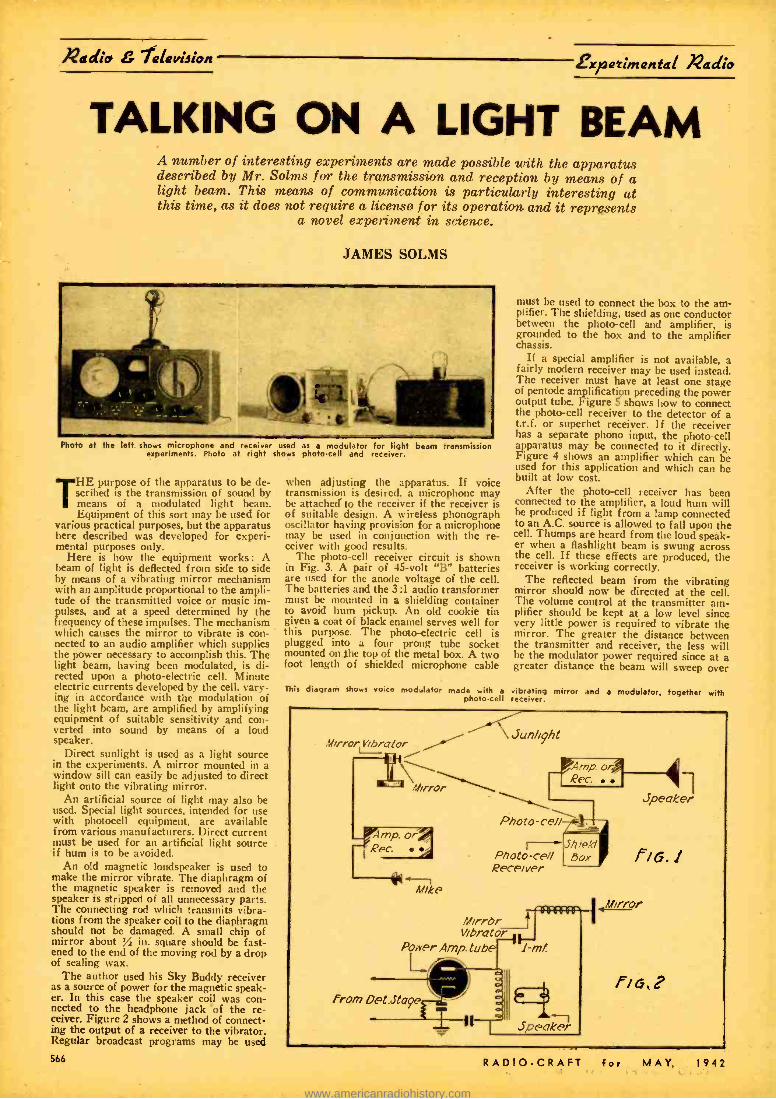
Radio 7alatiion fxfsatimantal Radio
TALKING ON A LIGHT BEAM A number of interesting experiments are made possible with the apparatus described by Mr. Solms for the transmission and reception by means of a light beam. This means of communication is particularly interesting at this time, as it does not require a license for its operation and it represents
a novel experiment in science.
JAMES SOLMS
Photo at the left shows microphone and receiver used as a modulator for light beam transmission experiments. Photo at right shows photo-cell and receiver.
THE purpose of the apparatus to be de- scribed is the transmission of sound by means of a modulated light beam. Equipment of this sort may be used for
various practical purposes, but the apparatus here described was developed for experi- mental purposes only.
Here is how the equipment works : A beam of light is deflected from side to side by means of a vibrating mirror mechanism with an amplitude proportional to the ampli- tude of the transmitted voice or music im- pulses, and at a speed determined by the frequency of these impulses. The mechanism which causes the mirror to vibrate is con- nected to an audio amplifier which supplies the power necessary to accomplish this. The light beam, having been modulated, is di- rected upon a photo -electric cell. Minute electric currents developed by the cell, vary- ing in accordance with the modulation of the light beam, are amplified by amplifying equipment of suitable sensitivity and con- verted into sound by means of a loud speaker.
Direct sunlight is used as a light source in the experiments. A mirror mounted in a window sill can easily be adjusted to direct light onto the vibrating mirror.
An artificial source of light may also be used. Special light sources, intended for use with photocell equipment, are available from various manufacturers. Direct current must be used for an artificial light source if hum is to be avoided.
An old magnetic loudspeaker is used to make the mirror vibrate. The diaphragm of the magnetic speaker is removed and the speaker is stripped of all unnecessary parts. The connecting rod which transmits vibra- tions from the speaker coil to the diaphragm should not be damaged. A small chip of mirror about % in. square should be fast- ened to the end of the moving rod by a drop of sealing wax.
The author used his Sky Buddy receiver as a source of power for the magnetic speak- er. In this case the speaker coil was con- nected to the headphone jack of the re- ceiver. Figure 2 shows a method of connect- ing the output of a receiver to the vibrator. Regular broadcast programs may be used
when adjusting the apparatus. If voice transmission is desired, a microphone may be attached to the receiver if the receiver is of suitable design. A wireless phonograph oscillator having provision for a microphone may be used in conjunction with the re- ceiver with good results.
The photo -cell receiver circuit is shown in Fig. 3. A pair of 45 -volt "B" batteries are used for the anode voltage of the cell. The batteries and the 3:1 audio transformer must be mounted in a shielding container to avoid hum pickup. An old cookie tin given a coat of black enamel serves well for this purpose. The photo-electric cell is plugged into a four prong tube socket mounted on the top of the metal box. A two foot length of shielded microphone cable
must be used to connect the box to the am- plifier. The shielding, used as one conductor between the photo-cell and amplifier, is grounded to the box and to the amplifier chassis.
If a special amplifier is not available, a fairly modern receiver may be used instead. The receiver must have at least one stage of pentode amplification preceding the power output tube. Figure 5 shows how to connect the photo-cell receiver to the detector of a t.r.f. or superhet receiver. If the receiver has a separate phono input, the photo-cell apparatus may be connected to it directly. Figure 4 shows an amplifier which can be used for this application and which can be built at low cost.
After the photo-cell receiver has been connected to the amplifier, a loud hum will be produced if light from a lamp connected to an A.C. source is allowed to fall upon the cell. Thumps are heard from the loud speak- er when a flashlight beam is swung across the cell. If these effects are produced, the receiver is working correctly.
The reflected beam from the vibrating mirror should now be directed at the cell. The volume control at the transmitter am- plifier should be kept at a low level since very little power is required to vibrate the mirror. The greater the distance between the transmitter and receiver, the less will he the modulator power required since at a greater distance the beam will sweep over
This diagram shows voice modulator made with a vibrating mirror and a modulator, together with photo -cell receiver.
Mirror I ibrcr[or f Mirror \ _
imp. or Rec.
Mike
Amp. or Rec.
Photo -cell
I-~ Photo -cell Receiver
3hiP/d ßoX
Mirror j Vibrator
Power Amp. tube 1 rnt
from Det.sta9e
Speaker
Speaker
f/G.1
'error
666 RADIO -CRAFT for MAY, 1942
www.americanradiohistory.com
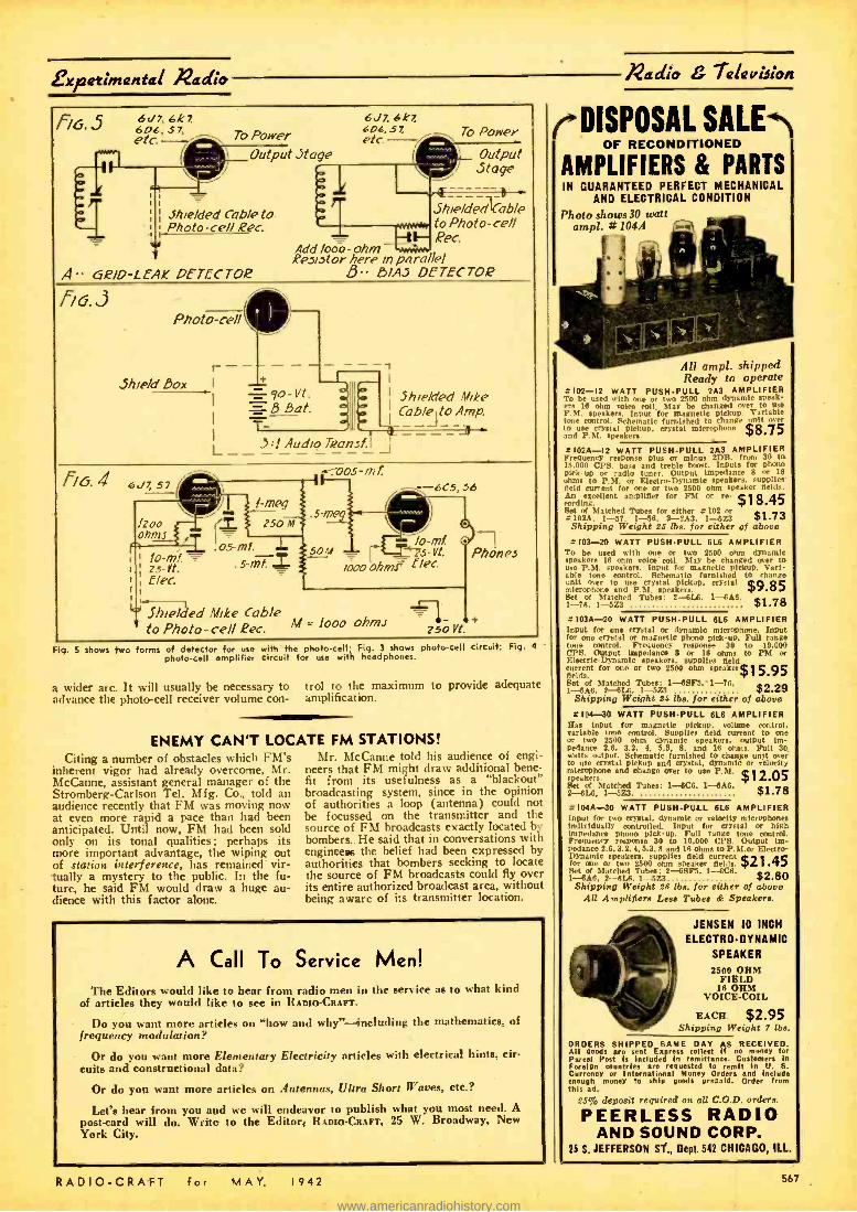
Expatimantal Nadia
56. S 6dß 6kz 606, 57, etc. To Power
Output Jtage
Shielded Cable to Photo-cell Rec.
A" oR /D -LEAK DETECTOR
Photo -cell e r
r- 3hie/d Box I
L
6 7. 4k2 606, 57, etc. -
Add Moo- ohm Resi.3tor here in parallel S B/AS DETECTOR
To Power
Output Stage
5/ne/decliCable to Photo-cell Rec.
7o-Vt. Bat.
I Shielded Mike Cable to Amp.
311 Audio Tzonsf.
s-mng
-6C5, 56
ó mf 50M
,000 0/7,m= f/ec
Shielded Mike Cable M =loco ohm to Photo-cell Rec.
o
o
z5o Vt.
Phones
+
Fig. 5 shows two orms of detector for use with the photo-cell; Fig. 3 shows photo -cell circuit; Fig. 4 -
photo-cell amplifier circuit for use with headphones.
a wider arc. It will usually be necessary to advance the photo-cell receiver volume con-
ENEMY CAN'T LOC Citing a number of obstacles which FM's
inherent vigor had already overcome, Mr. McCanne, assistant general manager of the Stromberg- Carlson Tel. Mfg. Co., told an audience recently that FM was moving now at even more rapid a pace than had been anticipated. Until now, FM had been sold only on its tonal qualities: perhaps its more important advantage, the wiping out of station interference, has remained vir- tually a mystery to the public. In the fu- ture, he said FM would draw a huge au- dience with this factor alone.
trol to the maximum to provide adequate amplification.
ATE FM STATIONS! 11 r. McCanne told his audience of engi-
neers that FM might draw additional bene- fit from its usefulness as a "blackout" broadcasting system, since in the opinion of authorities a loop (antenna) could not be focussed on the transmitter and the source of FM broadcasts exactly located by bombers. He said that in conversations with engineees the belief had been expressed by authorities that bombers seeking to locate the source of FM broadcasts could fly over its entire authorized broadcast area, without being aware of its transmitter location.
A Call To Service Men! The Editors would like to hear from radio men in the service as to what kind
of articles they would like to see in RADIO-CRAFT.
Do you want more articles on "how and why " - including the mathematics, of frequency modulation?
Or do you want more Elementary Electricity articles with electrical hints, dr- cuits and constructional data?
Or do you want more articles on Antennas, Ultra Short Waves, etc.?
Let's hear from you and we will endeavor to publish what you most need. A
post -card will do. Write to the Editor, RADIO- CRAFT, 25 W. Broadway, New York City.
RADIO -CRAFT fer MAY. 1942
I2adio 7alaviJion
( DISPOSAL SALE OF RECONDITIONED
AMPLIFIERS & PARTS IN GUARANTEED PERFECT MECHANICAL
AND ELECTRICAL CONDITION
Photo shows 30 watt ampi. # 104A
All ampi. shipped Ready to operate
5102 -12 WATT PUSH -PULL 2A3 AMPLIFIER To be used with one or two 2500 ohm dynamic speak' ere 16 ohm volee coil. Mar be changed over to use P. M. speaker.. input for magnetic ptcknp Variable tone control. Schematic furnished to change imo too, to use crystal pickup, crystal microphone $8 75 and P.M. speakers. P a102A -I2 WATT PUSH -PULL 2A3 AMPLIFIER Frequency response plus or minus 2DB. from 30 to 15.00n CPS. bass and treble boost. Inputs for phono Pick-up or radio tuner. Output impedance 8 or 16 ohms to P.M. or Electra- Dynamic speakers. supplies Meld current for one or two 2500 ohm speaker fields. An excellent amplifier for FM or re- $1 8.45 eording. J Set of Matched Tubes for either 0102 or .152A. 1 -57. 1 -56. 2-2A3. 1 -5Z3 $1.73 Shipping Weight 55 lbs. for either of above
5103 -20 WATT PUSHPULL 61.6 AMPLIFIER To be used with one or two 2500 ohm dynamic sneakers 16 ohm voice coil. May be changed over to use P.M. speakers. Input for magnetic pickup. Vari- able tone control. Schematic furnished to chango unit over to use crystal pickup. crystal $[1.O 85 microphone and P.M. speakers. 7 Set of Matched Tubes: 2--6L6, 1-6A6 1 -76. I -5Z3 $1.78 =103A-20 WATT PUSHPULL 6L6 AMPLIFIER Input for one crystal or dynamic microphone. Input for one crystal or magnetic phono pick-up. Full range tone control. Frequency response SO to 10000 ,,P8. Output impedance 8 or 16 ohms to I'M or Electric- Dynamio speakers, supplies field current for one or two 2500 ohm speaker $l 5.95 fields. Set of 3latched Tubes: 1- 68F5.- 1 -76. 1- -53A6. 2- Ii1.6, 1 -5Z3 $2.29
Shipping Weight 24 lbs. for either of above 5104-90 WATT PUSHPULL 61.8 AMPLIFIER
lias input for magnetic pickup, volume control, arieble tone control. Supplies field current to one
or two 2500 ohm dynamic speakers. output Im- pedance 2.6, 3.2. 4. 5.3, 8, and 18 ohms. Full 30 watt, output. Schematic furnished to change unit mer to use crystal pickup and crystal, dynamic or velocity microphone and change over to use P.M. $7 2.05 speakers. 1
Set of Matched Tubes: I-6C6, 1 -6AO, 2 -614. 1-623. $1.78 =104A-30 WATT PUSH -PULL 61.6 AMPLIFIER Input for two crystal. dynamic or velocity microphones individually controlled. Input for crystal or high Impedance phono pick -up. Full range tono control. Frequency response 30 to 10,000 Cl'S. Output im- pedance 2.6. 3.2, 4.5.3, 8 and 16 ohms to P.M.or Electro- Dynamic speakers. supplies field current for one or two 2500 ohm speaker flet,!,. $21.45 Set of Matched Tuber. 2- SSF5, 1-OCn. l-SAS. 2 -8t.a, 1-5Z3 $2.80
Shipping Weight 26 lbs. for either of above AU Amplifiers Less Tubes & Speakers.
JENSEN 10 INCH
ELECTRO- DYNAMIC
SPEAKER
2500 OHM FIELD
16 OHM VOICE -COIL
EACH $2.95 Shipping Weight 7 lbs.
ORDERS SHIPPED SAME DAY AS RECEIVED. All goods are sent Express collect If no money for Parcel Post Is included In rem ittanee. Customers in Foreign countries are requested to remit in U. S.
Currency or International Money Orders and Include enough money to ship goods prepaid. Order from this ad.
25% deposit required on all C.O.D. orders.
PEERLESS RADIO AND SOUND CORP.
25 S. JEFFERSON ST., Dept. 542 CHICAGO. ILL.
567
www.americanradiohistory.com
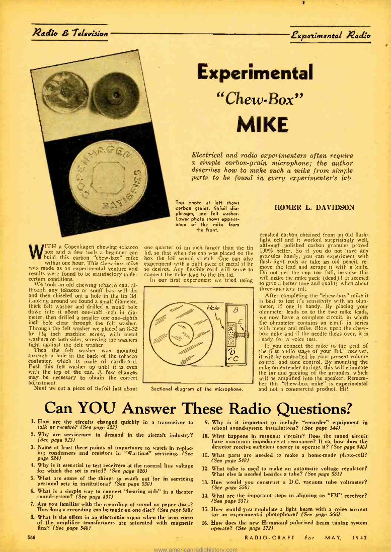
Radio 7alavision
WITH a Copenhagen chewing tobacco box and a few tools a beginner can build this carbon "chew -box" mike within one hour. This chew -box mike
was made as an experimental venture and results were found to be satisfactory under certain conditions.
We took an old chewing tobacco can, al- though any tobacco or snuff box will do, and then chiseled out a hole in the tin lid. Looking around we found a small diameter, thick felt washer and drilled a small hole down into it about one -half inch in dia- meter, then drilled a smaller one one -eighth inch hole clear through the felt washer. Through the felt washer we placed an 8 -32 by 1% inch machine screw, with metal washers on both sides, screwing the washers tight against the felt washer.
Then the felt washer was mounted through a hole in the back of the tobacco container, which is made of cardboard. Push this felt washer up until it is even with the top of the can. A few changes may be necessary to obtain the correct adjustment.
Next we cut a piece of tinfoil just about
Expatimantai Nadi*
Experimental "Chew -Box"
MIKE Electrical and radio experimenters often require a simple carbon -grain microphone; the author describes how to make such a mike from simple parts to be found in every experimenter's lab.
Top photo at left shows carbon grains, tinfoil dia- phragm, and felt washer. Lower photo shows appear- ance of the mike from
the front.
one quarter of an inch larger than the tin lid, so that when the cap was placed on the box the foil would stretch. One can also experiment with a light piece of metal if he so desires. Any flexible cord will serve to connect the mike lead to the tin lid.
In our first experiment we tried using
Sectional diagram of the microphone.
HOMER L. DAVIDSON
crushed carbon obtained from an old flash- light cell and it worked surprisingly well, although polished carbon granules proved 100% better. So if you do not have any granules handy, you can experiment with flash -light rods or take an old pencil, re- move the lead and scrape it with a knife. Do not get the cup too full, because this will make the mike pack (dead) 1 It seemed to give a better tone and quality when about three -quarters full.
After completing the "chew -box" mike it is best to test it's sensitivity with an ohm- meter, if one is handy. By placing your ohmmeter leads on to the two mike leads, we now have a complete circuit, in which the ohmmeter contains an e.m.f. in series with meter and mike. Blow upon the chew - box mike and if the needle flicks over, it is ready for a voice test.
If you connect the mike to the grid of the first audio stage of your B.C. receiver, it will be controlled by your present volume control and tone control. By mounting the mike on extender springs, this will eliminate the jar and packing of the granules, which will be amplified into the speaker. Remem- ber this "chew -box mike" is experimental and not a commercial product. Hi!
Can YOU Answer These Radio Questions? 1. How are the circuits changed quickly in a transceiver to
talk or receive? (See page 522) 2. Why are servicemen in demand in the aircraft industry?
(See page 523) 3. Name at least three points of importance to watch in replac-
ing condensers and resistors in "Wartime" servicing. (See page 524)
4. Why is it essential to test receivers at the normal line voltage for which the set is rated? (See page 526)
5. What are some of the things to watch out for in servicing personal sets in institutions? (See page 530)
6. What is a simple way to connect "hearing aids" in a theater sound -system? (See page 537)
7. Are you familiar with the recording of sound on paper discs? How long a recording can be made on one disc? (See page 538)
8. What is the effect in an electronic organ when the iron cores of the amplifier transformers are saturated with magnetic flux? (See page 540)
568
9. Why is it important to include "recorder" equipment in school sound -system installations? (See page 544)
10. What happens in resonant circuits? Does the tuned circuit have maximum impedance at resonance? If so, how does the detector receive sufficient energy to operate it? (See page 546)
11. What parts are needed to make a home -made photo -cell? (See page 548)
12. What tube is used to make an automatic voltage regulator? What else is needed besides a tube? (See page 551)
13. How would you construct a D.C. vacuum tube voltmeter? (See page 556)
14. What are the important steps in aligning an "FM" receiver? (See page 557)
15. How would you modulate a light beam with a voice current for an experimental photophone? (See page 566)
16. How does the new Hammond polarized beam tuning system operate? (See page 572)
RADIO -CRAFT for MAY, 1942
www.americanradiohistory.com

Naito i¡ook-uiae
U.H.F. Oscillator (Continued from page 555)
parts used in the construction of the oscillator.
LIST OF PARTS
CONDENSERS One liammarlund HF 35 mmf. condenser Four Aerovox .1 mf. tubular condensers One Aerovox 12 mf. condenser "Dandies ";
volts One Aerovox 16 mf. condenser "Dandies"; 200
volts One Aerovox .002 mf. mica One Aerovox .004 mf. mica One Aerovox .0001 mf. mica
RESISTORS Two I.R.C. 50,000 ohm, % watt One I.R.C. 2 meg. % watt One I.R.C. 50,000 ohm, 1 watt One I.R.C. 2250 ohm, 1 watt One Ohmite line -cord resistor One 280 ohm line -cord resistor
Piayram9 jot
%2adio L' 7alavieion
The Radio Experimenter This is a new department. If you have a new Hook -Up, send it along; a pencil
diagram will do. Be sure to include a brief description. All diagrams and descriptions accepted and published will be awarded a year's
subscription. Diagrams may be for receivers, adapters, amplifiers, etc. Send them 200 to Hook -Up Editor, RADIO- CRAFT, 25 W. Broadway, New York City.
TUBES One RCA 25Z5 or 2526 rectifier. One RCA 6J5G or 6J5 metal tube. One Chassis 7x7x2 ins. Electroalloy One Kurz -Kasch bakelite vernier dial 3 ins. One 3000 ohm volume control and switch Two Ilammarlund 2.5 mh. R.F. chokes
MISCELLANEOUS Wire, solder, bolts, nuts, 2 wafer sockets, 12 phone
tips. Five Combination jacks, to take phone tips or
banana plugs. One Clip (for cathode tap).
FM STATION SOUGHT FOR HOUSTON, TEXAS
FREQUENCY modulation for the largest city in Texas has been proposed through
an application for an FM construction per- mit filed by The Houston Printing Corpora- tion, publisher of The Houston Post and owner of standard station KPRC.
The new FM outlet would cover an area of 10,500 square miles, serving some 722,600 potential listeners who live within a 60 -mile radius of Houston. A channel of 46.5 mega- cycles has been requested, and it is under- stood that the station would be an outlet of The American Network.
One other application for FM service in Texas is also on file, seeking a station in Amarillo.
There are now 63 commercial FM trans- mitters authorized throughout the country. Twenty -four are on regular schedules, along with eleven experimental stations. The latest list of these FM outlets together with applications pending, as compiled by FM Broadcasters, Inc., may be had by address- ing the Editor of this magazine.
TELEVISION CONFERENCE CALLED
The Federal Communications Commis- sion met in informal conference with tele- vision permittees and licensees and repre- sentatives of the Radio Manufacturers As- sociation on April 9, in Washington, D. C., to discuss war -time television problems for the purpose of determining policies that may be followed regarding television broadcasting during the duration of the emergency.
The General Electric Company was granted construction permit (B1- PVB -88) on an experimental basis, for a new tele- vision relay broadcast station at New Scot- land, N. Y., to operate on Channel No. 8, 162,000 -168,000 kilocycles, 50 watts peak power and A -5 emission, for relaying pro- grams to applicant's television station WRGB, replacing experimental relay tele- vision station W2X1.
"LUNCH -BOX" RADIO RECEIVER
Richard Graham of Teaneck, N. J., sends is the diagram above of a two -tube portable receiver, operated from batteries. The whole outfit can be built into a "lunch-box." The author used different antennas one of which consisted of a couple hundred feet of insulated wire, wound around a small pole 3 feet long. Another antenna was 40 to 50 feet of wire laid on the ground. The tuned antenna coil shown in the diagram comprises 120 turns of No. 30 enameled copper wire, wound on a Wz -inch diameter
insulated tube. No "B" battery Is used.
IMPROVED TWINPLEX HOOKUP The diagram at the left shows an improved Twinples one -tube receiver circuit devised by Leonard Klafter of Newark, N. J. The tickler coil shown is connected to the first plate, and placed in an inductive relation
to the grid coll.
AN "ALL- PURPOSE" AUDIO AMPLIFIER
6P36
6v7G
o
a o
o
f
J.
T
V
573
assra
S1Dyr /6Nr 1W..r. r3N.s.
defewwww
AS
Abre
fi reour_avru 0v6/s.skrTio ;Octm/fe.
Tr64/Xr/,r.41I-.v[I AS.r.ctr Ael6lv lne,Ssrx.rirrá /uo.r.srtoAshro.
n:ohe,
This amplifier can be used with low impedance microphones of the Amperite velocity type and with double button carbon mikes. An input impedance of 400 ohms can also be obtained which, for all practica purposes, can be used for matching a 500 ohm line. The output transformer is universal and can match several different types of speakers. The power -supply uses an Input choke that is capable of carrying 200 mils. Of course, a choke of this size is unnecessary. It is used due to the fact that another amplifier is operated off the same power -supply. The 6N7 is shown as two tubes for simplicity in drawing. The 6í6's have
their screens tled to their plates. Robert L. Cambron, Gadsden. Alabama.
RADIO -CRAFT for MAY, I942 569
www.americanradiohistory.com
Net G 7e1evidiiR 2Kelti.R ¿X
Question Box COIL DATA
1942 1943 1944
CU
NOW it the Clue to make sure of the road ahead. After the present emergency, thou- sands of untrained, unprepared radiomen will be left behind. That's why CREI stresses the need now for a planned program of training
. to increase your technical ability so that you will be in a position to command an important job when the inevitable readjust- ment comes after the war. Make your present radio job pay you dividends in the years to come by investing in a CREI home study course in Practical Radio Engineering and prepare for advancement, increased pay and security in your chosen profession.
WRITE FOR FACTS TODAY! Our free booklet and personal recommendations may hold the answer to your success. In your inquiry, please state briefly your background of experience, education and present position.
CAPITOL RADIO Engineering Institute
Dept. RC -5, 3224 16th Street, N. W., Washington, D.C.
SOLVES EVERYDAY PROBLEMS-HELPS YOU GET AHEAD IN
LIFE How many take in figuring? Do you
you lost money because of ia- tly? Can. you figure
lydiscounts, in Interest quickly
. tanust and all the other calculations you meet up with in your and
daily life?
*n you because trouble qualifying lifying for
fort Navy pro. or
Here 1s the book that give you mathematics?
background in mathematics: that takes all the irritation and drudgery beout
of it. You don't need to he scared of thematics, cause here's the subject explained without frills. with- out useless computations. Sere'. the book for men in the armed forces: for bushier. technicians and craftsmen. explaining and ing e day mathematic problems in ea.y-to- nderstand words and illustrations. T., it's the key to a simple understanding of mathe- matics. It's a real home -study a in mathematics for the
who's alert to the importance of mathematics in the
man who's
ELEMENTARY MATHEMATICS EASY- SIMPLIFIED - PRACTICAL
CONTENTS OF BOOK. I. Arithmetic- Addition- Subtrction- Multi- plication- Div is I m,.
CHAPTER II. Factoring nd Cancellation-Frfctlons- Declmale- Percentage- Ratio --and Proportion. CHAPTER III. The Metric System. CHAPTER SV.
Row to Measure Surface. and Capacity CHAPTER V. Powers and Involution -Roots and Evo- lution. Maanual ds
Teccahn
CTuhrevre m oPmloetein - Logarit nne -Usee of
the Slide Rule. CHAPTER VII.
T Special Mathematics
CHAPTER VIII. Commercial Caleula- tions- Interest -Disconts -shoe Cut Arithmetic. CHAPTER IX. Weights and Measures -Useful Tables.
Send Stamps, Cain or Money order.
it ed cos [Géárn C..ad rist el 'i.peiuò Does. testa Pour
114 poe:
dkel. (Si, al e
te x e
ONLY
50c POSTPAID
II:I:MNIf11X Isla S. State St., RC -542, Chicago, III.
FOR SUCCESS IN PHOTOGRAPHY
Profit by 32 Years of Experience If Learn quickly hol. Full.timerexperts
largest. best y NDITDUAI.LY. Qualify now for this fascinet-
D P Iphy w plays Reldcme
industry. Resident r t o Mme study. Free booklet. / N. Y. INSTITUTE OF rk, NOORAPNY. Dpt 11, / 10 West 33 SL. New York. N. Y.
570
7
a
In my present receiver (home made) I ant using the Pilot Coil switching unit. I believe this unit carne out of the Pilot Converter (10 to 160 meters). The coils are wound on 1 inch coil forms and is quite a bulky object. i would like to do something about it.
I have ten quartz -Q coil forms 34. inch in diameter. Could you give me the coil data for these 34 inch forms, using a 2 -gang 140 mmf. condenser?
In the unit I am now using there are three windings, one detector, one oscillator plate, and one oscillator grid. Would I gain by using the so- called Antenna winding on the detector coil? The switch is so built if I wish to use the winding.
The tubes I now use are 617 detector, and 6C5 oscillator, In your September "Question Box" you have a diagram of a super -het using a 6K8. I have an HF ceramic base bantam 6K8GT and I also have 2- 1852s. Would you advise using the one tube, or a single tube in each section?
I also have 2 Meissner 1500 kc. IFTs that I wish to use in place of the present 456 IFTs. Would you advise them ? -G. B. Chieves, Bedford, Mass.
A. Tuning coil sizes for use with 140 mmf. tuning condenser. Detector Grid Antenna Coil Osc. Grid Osc. Plate
78 turns #26 25 turns 74 turns 50 turns 32 turns #22 10 turns 30 turns 20 turns 15 turns #14 5 turns 14 turns 10 turns
Detector grid and Osc. grid coils wound with size wire specified, enameled covered. Antenna and Osc. plate coils wound with #28 enameled wire.
You can use the single 6K8 tube as it will be simpler. If you substitute 1500 kc. IFTs, it will be necessary to experiment with the number of turns on the oscillator grid coil for proper "tracking."
AUDIO OSCILLATOR TUBE
Referring to the diagram of the variable tone audio oscillator shown on page 237 of the August issue, the second tube is labeled "76 ", but the "76" is a triode while the tube shown is a tetrode; can you set me straight on this matter? -L. N. Hultman, Rochester, N. Y.
A. The tube is actually a "76" but an error was made in showing the cathode as
a first grid. If the tube is recognized as being used simply as a rectifier, with the grid and plate tied together, the error is immediately apparent.
QUARTZ CRYSTAL MOUNTING
When using a tube socket as o re- ceptacle for a plug -in quartz crystal, which two prongs are used? -F. Stark, Calumet, Mich.
A. When the five -prong socket is used, the plate and cathode contacts are used since these have the correct spacing to en- gage the crystal mounting pins (4" be- tween centers).
PHONO- OSCILLATOR
What size coil forms were used in the Portable Radio -Phono oscillator shown on page 104 of the June issue? -F. Bam- ford, Orange, N. Y.
A. The coil form is a Radio -Crafter type "C" form, having a diameter of i inch and a length of 2 inches.
BAND- SWITCH TROUBLE
I have an 11 -tubs' all -wave receiver that has given me continual trouble at the coil switch. I wonder if I could replace this band -switch with a series of small knife switches ? -J. J. Meehan, Morton, Pa. A. It would be practically impossible to replace the rotary coil switch with a number of knife swatches, because of the much greater space that would be taken up by the knife switches. The lengthened leads also would result in much poorer operation due to higher losses, besides the inconvenience of so many switches to op- erate. Why not replace the old switch with a modern low -loss band- switch?
CRYSTAL TO WORK SPEAKER
Can you supply a diagram of a crystal receiver capable of operating a
Flpeaker? -C. Caldwell, Talahassee,
A. Without additional amplification, re- quiring the use of tubes, it is usually im- possible to operate a loudspeaker from a simple crystal receiver.
10 BEST RADIO BOOKS 10 CENTS EACH RADIO FANS EVERYWHERE -these fine amazed at the wealth of information con - ten cent text books give you an excellent tained In these handy books. Excellent for foundation for the study of RADIO. They are reference -ideal for every technical library. clearly written, profusely illustrated and con- YOUR MONEY BACK if you are not satisfied. tain over 15,000 words in each book. You'll be PROMPT SHIPMENTS
N.. I -HOW TO BUILD FOUR DOERLE SHORT No. 5- BEGINNERS' RADIO DICTIONARY WAVE SETS No. 6-HOW TO HAVE FUN WITH RADIO No. 2 -HOW TO MAKE THE MOST POPULAR No. 7 -HOW TO READ RADIO DIAGRAMS ALL -WAVE I- AND 2 -TUBE RECEIVERS No. 8-RADIO FOR BEGINNERS No. 3- ALTERNATING CURRENT FOR BEGIN-
NERS No. 9- SIMPLE ELECTRICAL EXPERIMENTS No. 4-ALL ABOUT AERIALS No. 10- TELEVISION
BOOKS ARE ALL UNIFORM livery book In the ORRNSBACK EDUCATIONAL. LIBRARY has 3' pages -with Illustrations varying from 30 to 66 in number. Each title volume contains over 15.000 words . Positively radló. "realest book buys! if you do not think thcso books north the price asked. return them In 24 hours and your mopes will be instantly refunded.
RADIO PUBLICATIONS 25 WEST BROADWAY NEW YORK, N. Y. RADIO PUBLICATIONS, Dept. RC -6.42 25 WEST BROADWAY. NEW YORK, N. Y. Gentlemen: Please send Immediately, POSTPAID. the book numbers circled below, I am enclosing cents -each book being 10c.
1 2 3 4 5 e 7 II
Bend FREE Holing of 48 now loo publications.
'I NEW
Id NEW
Name Addre..
City e Remit by check or money order-register letter if
St you
at Orni!cash or unused U. S. postage stogies
.MAIL COUPON TODAYI
RADIO -CRAFT for MAY. 1942
www.americanradiohistory.com
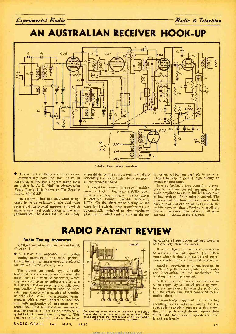
expatiinantal nadlo /1eadio lalaviiion
AN AUSTRALIAN RECEIVER HOOK -UP
IF you want a $150 receiver such as are commercially sold for that figure in
Australia, follow this diagram taken from an article by A. G. Hull in Australasian Radio World. It is known as The Breville Radio, Model 237.
The author points out that while it ap- pears to be an ordinary 5 -tube dual -wave receiver, it has several improvements which make a very real contribution to the set's performance. He states that it has plenty
5 -Tube, Dual Wave Receiver.
of sensitivity on the short waves, with sharp selectivity and really high fidelity reception on the broadcast band.
The 6J8G is mounted in a special cushion socket and gives frequency stability down to 13 meters. Easy tuning on the short waves is obtained through variable selectivity IFT's. On the short wave setting of the wave band switch, these transformers are automatically switched to give maximum gain and broadest tuning, so that the set
is not too critical on the high frequencies. They also help in getting high fidelity on broadcast programs. -
Inverse feedback, tone control and com- pensated volume control are used in the audio amplifier to assure full brilliance even at low settings of the volume control. The tone control functions on the inverse feed- back circuit and can be set to attenuate the middle register, thus affording exceedingly brilliant response. The values of all com- ponents are shown in the diagram.
RADIO PATENT REVIEW Radio Tuning Apparatus
2,250,761 issued to Edmund A. Gschwind, Chicago, Ill.
A NEW and improved push button tuning mechanism, and more particu-
larly a tuning mechanism especially adapted for use with radio receiving sets.
The present commercial type of radio broadcast receiver comprises a tuning ele- ment, such as a variable condenser, which requires very accurate adjustment to tune in a desired station properly and with good tone quality. A push button tuner for such sets must therefore be capable of rotating or otherwise moving the associated tuning element with a great degree of accuracy and with uniformity of movement in re- peated use. Cost limitations in commercial practice require a tuner to be produced in quantities at a minimum of expense. This requires in turn that the parts of the tuner
The drawing above shows an improved push button tuning device for use with radio receivers. The push button rods are independent of the mechanism
which rotates the tuning condenser.
be capable of production without working to extremely close tolerances.
It is an object of the present invention to provide a new and improved push button tuner which is simple in design and opera- tion and adapted for commercial production.
Another provision is a construction in which the push rods or push button slides are independent of the mechanism for rotating the tuning element.
A third feature gives a construction in which separately supported actuating mem- bers are interposed between the push rods and the rotary cam shaft connected to the tuning element.
Independently supported and co- acting operating levers actuated jointly by the push rods, is another purpose of this inven- tion; also parts which do not require close dimensional tolerances to operate accurate- ly and uniformly.
571 RADIO -CRAFT for MAY, 1942
www.americanradiohistory.com

Xadio 7alaviJion Radio /bat ants
RADIO& TELEVISION
PRICE 504
G.W.íhuárt eW2AMNe
-- i.a-- -- -----_--_
148 PAGES 6 z 9 INCHES
OVER 150 RADIO DIAGRAMS and TECHNICAL PHOTOGRAPHS
RADIO AND TELEVISION 25 West Broadway New York, N. Y.
i
Your Money Back - If the RADIO AMATEUR COURSE does not represent the greatest book value ever offered to the radio
5o "fans" for J 10
TO convince you that there isn't a better book buy today, the pub-
lishers of the RADIO AMATEUR COURSE make the sensational offer of a money -back guarantee on such a low- priced book. Stop in at any of the many dealers handling this book and examine it. See for yourself if the RADIO AMATEUR COURSE isn't just the book you've always wanted.
Printed on the finest coated paper -well illustrated attractive 4 -color cover-complete with radio informa- tion you mast have. It contains a step -by -step program for obtaining
short -wave radio education.
Written by George W. Shaart, WtAMN
foremost short -wave authority
RADIO AND TELEVISION 25 West Broadway, New York. N. Y.
Gentlemen: I enclose herewith my ittanre of Fiftyy Cents
m(SOOc) for whirl, .leave twat POST -
Remit check or money °D or; r deter letter if you send send
cash or unused V. S. Postage stamps.)
Nemo
Address
City stato &C.5.42
POLARIZED TUNING SYSTEM No. 2,272,839 issued fo John Hays Hammond, Jr., Gloucester, Mass.
This invention pertains to an improved radio transmission system for producing two carrier waves of the same frequency, but with different planes of polarization, the phases of the radiations having any desired relations.
The invention also provides polarized re- ceiving means, which may be rotated so as to eliminate any undesired interference, without interfering with the reception of the desired signal.
The present method accomplishes selec- tivity of transmission against intentional or other interference by similar signals of the same carrier frequency, and may be prac- tised with any type of communication such as continuous wave telegraphy or telephony, facsimile transmission, etc.
In the diagram shown an ultra shortwave transmitter is provided with two radiators or antennas, one transmitting a beam df waves in a horizontally polarized plane,
Rec. Aerial 1
2e
IS
Vert waves
A new system of tuning has been perfected, utilizing two beams of waves, one horizontal- ly polarized, the other vertically polarized.
672
while the other transmits a beam of waves vertically polarized. By suitably turning the radiators and their reflectors, the respective polarization plane of either of the wave beams may be changed. The two radio beams are concentrated on to a single col- lecting antenna system, shown at the right and the receiving antenna and its reflector may be rotated to any required angle. By rotating the receiving antenna and its re- flector, it becomes possible to make the re- ceiver respond to either the vertically polar- ized or the horizontally polarized radiation, or in part to both.
Since interference in general is usually of plane polarized nature, it is evident that by rotating the collecting antenna system until its axis is perpendicular to the plane of polarisation of the interference, it is possible to eliminate this interference almost entirely, without affecting the intensity of the desired signal from the transmitter.
It is thus seen that this arrangement pro- vides a means of transmission and reception quite free from disturbances of plane polar- ized radiation, of the same frequency and general nature as those being conveyed; thus an added method of selectivity is pro- vided over and above any selectivity which may be provided by the nature of the trans- mitting and receiving circuits.
TELEVISION IMAGE PROJECTOR No. 2,276,750 issued to Manfred von Ardenne.
This invention covers a television image projection system, wherein optical means are provided for projecting a television
a / p
lr/.c'y.s 14\ R-m
V p -_;
r /a,Q"-y SYNCNRONOr/S
MO/VR p image upon a viewing screen. Contrary to the usual television projection method, with this invention the image is sustained uni- formly as a whole on the projection screen. The disappearance or absence of each in- dividual line of the entire screen occurs during a brief time period only, as com- pared to the customary duration of the individual lines, which for example, may be only 5 to 10 percent of the duration of the frame image.
Despite the briefness of this period of darkness in the devices disclosed, says the inventor, a flickering is noticeable, espe- cially where the field or frame frequency is low (for instance 25. and less). This condi- tion persists even though the period of darkness does not occur simultaneously over the entire image but exists in the form of a moving dark band over the image field in accordance with the formation of the image in a line by line manner. The elimina- tion of this disturbance is of particular im- portance because with such elimination the operation can be carried out with the small- est number of images or frames per second which is possible to reproduce the move- ment so that an especially narrow fre- quency band of the transmission channel will be sufficient. Furthermore, lower car- rier frequencies may be used.
It is proposed to eliminate the disturb- ance due to flickering by introducing an intermittent projection similar to that in ordinary moving picture projectors.
RADIO -CRAFT for MAY. 19.42
www.americanradiohistory.com

Xadio Patenti )ladio 7alavieion
JYMC. gErtw/r
.11111&.06
TELEVISION INDICATOR
No. 2,275,026 issued to Aide V. Bedford. Collinswood, N. J. Often times it is desirable to point out a
certain figure or object on a television image screen by means of an arrow, during a lec- ture, for example. This invention provides an electrical means whereby an indicating arrow may be caused to appear on the tele- vision screen at the receiver and at any desired location on the screen. The inventor does this by utilizing a second cathode ray tube in which the position of an arrow can be selectively picked up and the currents corresponding to this arrow (image) super- imposed on the signal emanating from the iconoscope or regular image pickup tube. By providing the proper deflection control means, associated with the cathode ray tube generating the signal representative of the
arrow, the transmitter operator may posi- tion the arrow at will in the field of the television picture. In the case of the auxili- ary cathode ray tube in which the image of the arrow is scanned, the deflection of the scanning ray is accomplished by means of a pair of deflecting coils, located in a deflecting yoke, which is rotatably mounted on the neck of the cathode ray tube. The arrow or other indicating symbol may be rotated at the will of the operator by means of a suitable control knob; this knob whet rotated also causes the deflecting yoke to be rotated. Means are also provided for moving the indicating symbol sideways or up and down on the picture at will ; by add- ing or subtracting a stage of amplification, the arrow may be made black or white.
RADIO DISTANCE METER cyclically with such extreme rapidity, that the waves which have been transmitted and reflected back to the transmitter arrive at it at the instant, when it is again trans- mitting waves having a recognizable fre- quency characteristic with respect to the reflected waves. The frequency with which the frequency of the radiated waves is varied is then a measure of the desired distance.
2,248,599 issued to E. F. W. Alexander - son, Schenectady, N. Y.
IT bas been found that radio waves may be used to measure the distance between
two points with very simple apparatus, by the use of a new and fundamentally different method. In practicing the present invention, waves of very high frequency are propa- gated toward the object whose distance from the observer is to be measured and standing waves are thus created. The fre- quency of the propagated waves is varied
In Fig. 2 there is illustrated a receiver which is designed to indicate the intensity of beat frequency components between the transmitted wave and the wave reflected from the surface whose distance is being measured. When the frequency of the re- flected wave returning to the receiver cor- responds closely at all times to the fre- quency of the wave passing directly from the transmitter to the receiver, there are a minimum of beat frequency or heterodyne components. Conversely, when the fre- quency of the oscillator of Fig. 1 varies at such speed that the reflected wave reach- ing the receiver attains its lowest frequency, at the instant when the wave coming di- rectly from the transmitter attains its highest frequency, there are a maximum of beat frequency components. Either of these conditions may be used to indicate distance
RADIO -CRAFT for .MAY, 1942
AIRCRAFT NAVIGATION 2,245,246 issued to Ernst F. W. Alexan-
derson, Schenectady, N. Y.
THIS invention is a system comprising a series of trail transmitter stations
spaced at relatively wide intervals along the predetermined cross- country flying course or trail, and arranged to transmit course radio signals and altitude radio signals, and similar transmitter stations, but spaced at relatively short intervals, located at the landing fields and arranged to transmit course signals and altitude sig- nals along the predetermined glide paths leading to the landing fields from the cross -country course or trail.
The course signal antennas at each sta- tion both along-the cross country trail and at the glide paths are preferably so ar- ranged as to provide at each station two beams directed horizontally with vertical polarization, the beams being directed re- spectively a predetermined number of de- grees to the right and left of the course. A dot -dash method of keying the course signal antennas is preferably employed.
The altitude signal is radiated at each station by two antennas, spaced apart in the direction of the course, and each pro- viding a radiation directed upwards with a sharp directivity in the direction of the course but spreading fan -shape along the course. The two altitude beams at each sta- tion create an interference pattern in space, so that the signal periodically disappears when the plane flies through the pattern.
The system provides, on the aircraft, a course and altitude signal receiving means which preferably comprises a single receiver apparatus. For the course signal indication the receiver apparatus includes a visual course indicator of the dot -dash type, wherein the instrument needle goes to the right or to the left if the aircraft is off course, but remains on neutral when the aircraft is on course. For the altitude signal indication the receiver apparatus includes means, preferably providing a visual indica- tion, responsive to the pulses created in the radio receiver by the interference pattern which is set up by the altitude signal trans- mitter. The altitude indicating means is so arranged that in flying the aircraft through an interference pattern of a given form, for a predetermined ground speed. the instru- ment indicates directly in response to the pulsation frequency whether the aircraft was at the correct altitude as it passed through this interference pattern.
573
www.americanradiohistory.com
Radio g 7elevieion Radio Ateaet
IIATAPRINTS App \ ,,ter' l s-=
P..----i.: jt
NEW Data
TESLA -OUDIN COILS 20e Ea. in order for 10
-,`, +`[r (Data and Drawings only.) 86" Sp'k Tesla -Ondin Coil 40e (1 K.W. Exc. Trf. Data incl.)
rI 8^ Sp'k Tesla -Ondin Coil 40c (3( K.W. Exc. Tri. Data incl.) 8 Spit Oudin; 110 Vt.
Kick Coil" type 40e u 8' Tesla Works on Ford Coil 40c
rsp'k Vibrator Ri.Freq. Coil ¿Oc
16 ft. Sp'k. Ondin Coil & Exciter 75e
Induction PIPE L ORE LOCATOR
Induction Type, Data 40e
Radio Typs 40e
More DATAPRINTS 40c each! 6 Meter Superhet, Electric Refrigerator % Meter Tr. & Rec. Wheatatone Bridge 20 A.C. Probe. & Ans. Weld. Transfo 2 R.W. 20 Telephone Hook -ups 100 Mech. Movements Rewinding Armatures 20 Motor Hook -ups String Galvanometer Television Rook-up 20 Simple Bell Circuits 20 Elec. Party Tricks Steel Wire Recorder! Solenoids and Magnets Water Wheels -get list. Water Turbines Fry Eggs on Ice! Photo Cell and Relay Experimental Photo- Ring 4 belle: 2 Wires
phone 20 Tesla Tricks Radio Control for Models Polarized Relay
Diathermy Apparatus Induction Balance Inductor Organ Electric Pipe Thawer
Special Prices: 4 prints $1.00; 10 for $2.00; Single. 40e each. Get New Catalog 100 A.
The DATAPRINT Co. Lock Box 322D, Ramsey, N. J.
OPPORTVNlTy AD-LETS Adiertlsuu-n s in 111: .cut111 r for each insertion. Name. address and initials mum be Included at the above rate. Cash should accom- Pan, all classified advertisements unless placed by an accredited advertising agency. No advertisement for less than ten words accepted. Ten percent dli- count six Issues, twenty percent for twelve Issues. Objectionable or misleading advertisements not ac- cepted. Advertisements for dune. 1912 issue, must rearh us not later than May 10, lii12. Radio -Craft 25 W. B'way New York, N. Y.
EDUCATIONAL COURSES CORRESPONDENCE COURSES AND EDUCATIONAL books, slightly used. Sold. Rented. }Stchanged. All sub- ject.. Satisfaction guaranteed. Cub paid for used courses. Complete details and bargain catalog FREE. Write NELSON COMPANY. 500 Sherman, Dept. C -242, Chicago. ONE. TWO AND THREE -TUBE SET PLANS: "TEI..s0 ", ' l'ellotron ", Telio-Rullder" Radio -Builder", 'Radio. Telio" -All 25c. Telloradio, , 524 Fairbanks Avenue, Oakland. California. WANTED: RIDER MANUALS. TESTING EQUIPMENT,
te. Walter Wishner, Sioux Falls, S. C. SPOT CASH UP TO 85.00 FOR NEW RADIO !EVEN- time. Teliotron, 524 Fairbanks Avenue. Oakland, Cali. ornia.
Do you need BINDING POSTS?
The XL USN POST r nn its Sprig Action r saure n. Constant Contact and
Manufactured In All Aluminum Type It at 12c each. Aluminum Body. Bakelite Top Type I nt arc each. Types CP or NP. ALL BRASS-STAIN- LESS STEEL SPRING & PIN. PROVEN by 240 HR. SALT SPRAY TEST as NON. CORROSIVE at Sac each.
Mansil cturere and Deal. Liberal Disrnunt.
..
X. L. RADIO LABORATORIES 420 Wat Chlago Ave,, Chicago, Ill.
LEs Correspondence Courses In
RADIO etjELECTRICAL £NGIN££RINC ELECTRICAL ENGINEERING °,t
trM'a Wit)Mid Prepare rAu If, u caL un,or.tenfforn u.ki cure
RADIO EN6INEERIN6 **'; " ̂ °° ^ ..di fps Trame
Ile AAre aa. photo m technicianY to a n
I[>mer. kite ru,urn. f notoma l ahane nuns. 521. either douta. Dtacci paYm plan. Get r plea et rhooi talogiatmAent malsaine. complete detail*. esxxxNOD Nowt
tIUSItr 118111Ea1N8 ae800t w sit -eta LINCOLN. NISI. FREE 574
Plaque Award Announcement THE editors are pleased to announce
that the handsome plaque previously awarded for photos of the best amateur radio station will be hereafter awarded
to the person submitting the best photo of a Radio Listening station (or post). If you are a short -wave listener, here is a good opportunity to win the plaque which this magazine will award each month for the best photo received. The photo should be accompanied by a 300 -word description, ex- plaining the type of aerial or aerials used, their dimensions and arrangement, the make of receiver used and whether or not any recording device is available for making
Here is the "Award of Honor" Plaque which meas- ures 5" x7" in size. It is handsomely executed in colors on metal, and is framed, ready to hang on the wall. The name of the winner will
be suitably inscribed.
FOR THE DURATION OF THE WAR -Plaque will be awarded for best "Listening
Post" photo. Attach a brief description not
longer than 300 words, describ- ing the general line -up of the apparatus employed, the size, type and number of tubes, the type of circuit used, name of commercial receiver - if not home -made.
State briefly the number of continents heard the total num- ber of stations logged or con- tacted, and other features of general interest. Mention the typa of aerial system.
Important - Enclose a good
liphotograph of yourself, if your
keness does not appear in the picture!
You do not have to be a reader of RADIO -CRAFT in order to enter the contest.
Address all photos and station description to Editor, "Listening Post" Photo Contest, c/o RADIO -
CRAFT. 25 west Broadway, New York, N. Y.
a record of code or phone messages picked up.
If the owner of the "listening post" is a member of a local defense unit, he should also state this in his letter. (The editors will be pleased to receive articles on the subject of local defense, written from a radio listening post angle.)
The photos of your "listening post" should include the owner's picture or otherwise a small photo of the station owner may be enclosed with the picture of the outfit. The pictures must be sharp and clear and should not be smaller than 5 x 7 inches,
..,t..t,m,eet eatwe,ewtaw,low,wetwat.eteartwe.we.wt.eo.m..metee, _
"!..r. . -
THIS -ward of Honor
resented to
,joJtn. Doe
by
f RADIO & TELEVISION
MAGAZINE for the Best
PHOTOGRAPH of an
AMATEUR RADIO STATION
Submitted in the monthly
Amateur Station Photo Contest
Ji. genne6och, Editor
rl
l
pl
. _.. _ . _ - ' __ __ ' _ ,l' I
0111104a,ea,ee,.esaw ®tait.11ai,.a.iatt,tletllbeal,ma.ee,i,aeeea.w.s
MORE "HAM" LICENSES ISSUED The F.C.C. is now ready to issue the
1500 operator licenses which have been earned since December 7 and which have been held on their desks since that date. This number will bring the total number of amateurs close to 60,000. Of this number, it is estimated that more than 10,000 are already in military communications serv- ice. The object of this release of licenses to successful candidates is to replenish the supply of technicians and communicators for both military and non -military radio openings.
A "ham ticket" has long been recognized as the "open sesame" to a good radio job; today it is the virtual equivalent to a diplo- ma or even a college degree, if one may judge by the special ratings and pay open to hams in military service and the number of calls for qualified amateurs received from the radio industry daily at the head- quarters office of A.R.R.L. "Ham tickets" can be used as qualification for admission to advanced military grades. The Navy grants immediate rating as radioman, sec- ond class, equal to four full promotions over the normal entrance rank, to holders of amateur Class A or B. Likewise, the Army offers specialist ratings in communi.
cations work in its signal corps for quali- fied amateurs.
Non -military government radio openings also often specify_ the holding of an ama- teur license: One bureau ttrutts qualified amateur radio operators capable of han- dling 25 w.p.m. in code. The F.C.C. wants amateurs "to augment the Commission's staff in patrolling the radio spectrum and detecting and locating illegal and subver- sive radio stations." When the supply of professional radio engineers was exhausted many months ago, the radio industry turned to the amateur body as constituting the only other personnel trained in radin communication. In particular, amateurs are being called for by companies engaged in the production of "radiolocator" gear, an entirely new radio technique, since hams have long been noted for their ability at improvisation and quickness to grasp new ideas.
If you need more information concerning the jobs, both military and non -militay, contact A.R.R.L., giving such salient facts as your qualifications, the kind of job pre- ferred, salary expected, etc. -(From A.R.R.L., with interscription by the editor of "The Arc," Asheville, N. C.
RADIO -CRAFT for MAY, 1942
www.americanradiohistory.com

'PmatQat Radio
A FEW DUMMY ANTENNAS In No. 1 a second inductance is used
similar to the tank coil with a variable con- denser the same as Cl. The lamp is in cir- cuit with a clip on the inside lead. This is clipped at various points along the coil until the transmittér final is drawing the rated number of mils. At the same time the lamp should reach a peak brilliancy. Compared to its brilliancy on the light lines will indi- cate roughly the output of the rig.
In No. 2 is indicated a simple rig, un- tuned. When the lamp's brilliancy reaches maximum with the tube plate running at normal such a dummy is functioning prop- erly.
No. 3 shows a dummy antenna that bet- ter approaches the desired state of effi- ciency. A link connects the tank circuit to the dummy inductance. Both inductances are alike, as are Cl and C2. One or two turns of the link are wrapped around the cold end of the tank and by means of clips, attach to as many turns as are necessary on the dummy inductance. One or two each side of the center is about right. Sufficient lamp wattage is then clipped to the induct- ance as indicated. The lamp wattage should approach that of the transmitter's output. When the condenser C2 is operated and the clips are properly placed, with the tube drawing normal currents, such a dummy will more truly function as a normal an- tenna- without radiating. Its action is sharper than the two former and resonance with the transmitter more clearly defined.
A good dummy antenna is as necessary to a station as a good monitor and fre- quency meter. Tests can be carried on for hours without interfering with others on the air and the transmitter brought to a stage of perfected operation, just as though the regular antenna was being used. -L. B. Robbins.
i INDUCTANCES
ARE THE SAME
C2, SAME AS / C/ CAPACITY
F/G /
FIG. 2
LAMP, SIZE FOR PROBABLE OUTPUT OF TRANSMITTER
CLIPS %
CLIPS
NECESSARY WATTAGE
( AMP
FiG. 3
/ TURN LINK
INDUCTANCES ALIKE AND CI & C2 SAME
CAPACITY
C2
Various hook -ups of dummy antennas.
THE office of a dummy antenna is to save "jamming" the air with test signals
and to act with similar characteristics as the antenna, so tests can be made in tuning up the rig. Its make -up is a matter of resist- ance and capacity to match the "sky -wire" and can be composed of pure resistance such as the non -inductive type or an electric lamp which is better for amateur use be- cause it gives visual indication. The capac- ity can be any suitable condenser. An in- ductance should be used to match that of the transmitter tank.
17 CENTS PER FOOT ANTENNA! Here's a wonderful vertical antenna
which costs less than 17c per foot. The only materials needed are as follows :
1 Permax 10 meter vertical steel mast (No. 318 -M)
I twenty foot 2" x 2" wood pole
Enough single or double transmission line to receiver
Sufficient guy wire to hold mast steady when winds blow
You will also need 3 pieces of wood size 4 x 6 x 1 boiled in paraffin.
The diagram illustrates everything in the construction of this antenna. A few point- ers, however -it would be advisable to give the wooden pole two coats of paint to re- sist the weather. Care should be taken when putting up the mast, as it isn't quite as easy as it looks. Perhaps you can get some- one to help you and do the job right. The antenna I have here has been in use close to about one year and the results have been amazing, not only on the ultra high fre- quencies, but on the other bands as well. I have even used this antenna to transmit, as it radiates well on the ultra high frequency bands. It can be used 54 wave on 10 and 20, and 1A wave on 5 and 10. -Biago Trimboli
RADIO -CRAFT for MAY, 1942
10 METE Le
FL EME NT
WOODEN SPACER HOLDING ELEMENT /N
PL ACE
LEAD IN
GUY W /RE WITH / NSUL ATOP
WOODEN MAST
REINFORCED BASE
Radio ,g lG1QI Lion
/here's a SHORTAGE of
RELAYS by GUARDIAN
now being diverted to DEFENSE...
* Guardian products and Guardian engi- neering have been recognized and ac- cepted by the U. S. Armed Forces to such an extent -that unless yours is a defense job, we find it impossible to furnish some of the best relays Guardian has ever produced. If we only could, Man, what a rig you'd have!
A year ago, you couldn't have bought re- lays with the high capacity and small size that Guardian is furnishing to our fighting forces today. So, keep a date with the best relays ever built when you're back at your rig in 194 ?.
RELAYS by GUARDIAN Guardian's contribu- tions to radio defense are in the "walkie- talkie", tank radios, radio directional navi- gation, and a lot of "gimmicks" and "gad- gets". They have more of a lead on old prac-
Modal tices than the retreat - A -100 ing Nazis have on the Relay Russians!
*Guardian is going ahead!
RADIO AMATEUR RELAYS Standard A -100, A- 100 -C. Antenna Relays AISIMa. Insulated Operate on 110 V. -50 to 60 cycles A.C. A -100 Double Pole- Double Throw A -100 -C Single Pole -Double Throw (R -100 Relays AISIMag Insulated. Same Rating as the A -100 Relays.) R100 -C Single Pole -- Double Throw R -100 Single Pole Single Throw
See Your Jobber Before Stock on Hand Is Depleted.
GUARDIAN `J ELECTRIC 1622 West Walnut Street Chicago, Illinois
DEFENSE
LARGEST LINE Of RELATS SERVING AMERICAN INDUSTRY A
#aadsat #aadivattati Our Headphones are used by the United States, Canadian, New Zealand and South Afri- can Governments as well as other Governments not directly in the war. Folder C -5 illustrates rugged, unusually sensi- tive, dependable Cannon - Ball Headsets. Write ..
Scientifically Built
Heavy bar maw- neta greatly Ftery.
their en,.
C. F. CANNON COMPANY SPRINGWATER, N.Y.
RADIO ENGI NEEAING, broadcasting. aviation and pollee radio. servicing. marine radio telegraphy and telephony. Morse telegraphy and railway accounting taught thoroughly. 48 weeks' Engi- neering course equivalent to 3 years of college .din work.
All expenses low. Catalog free. School established 1874.
The Dodge Institute, Monroe St., Valparaiso, Ind.
575
www.americanradiohistory.com

Radio TQIQViJion
NDW -A REALLY HIGH- POWERED-
Radio Engineering Library
NOTE: The Library comprises a selection of books culled from leading Mc- Graw -Hill publications in the ra- dio field.
especially selected by radio specialists of Mc- Graw -Hill publications
to give most complete, dependable coverage of facts needed by as whose fields are grounded on radio fundamentals
available at a special price and terms THESE books cover circuit phenomena, tube the-
ory, networks, measurements, and other sub- jects --give specialized treatments of all fields of practical design and application. They are books of recognized position in the literature -books you will refer to and be referred to often. If you are a practical designer, researcher or engineer in any field based on radio, you want these books for the help they give in hundreds of problems throughout the whole field of radio engineering. 5 VOLUMES, 3319 PAGES, 2299 ILLUSTRATIONS I. Eastman's FUNDAMENTALS OF VACUUM TUBES 2. Terman's RADIO ENGINEERING 3. Everitt's COMMUNICATION ENGINEERING 4. Hund's HIGH FREQUENCY MEASUREMENTS 5. Bonney's RADIO ENGINEERING HANDBOOK IO days' examination. Easy tense. Special price under this offer less than nooks bought separately. Add these standard works to your library now: pay small monthly l,I..talltnents, while you use the books
10 DAYS' FREE EXAMINATION -SEND COUPON
McGraw -Hill Book Co., 330 W. 42nd Street, N. Y. C. Send me Radio Engineering Library. s vols.. for 10
days' a itutlon on approval. In I0 day. i will send $3.00 plus few renta postage, and 53.00 monthly $24.00 Is paid, or return brook. id. (We pay post- age on order. accompanied by remittance of first in. s allment.)
Name
Address
City and State
Position
Cnmpanv RC-$-42
MATHEMATICS FOR RADIO
AND COMMUNICATION by GEORGE F. MAEDEL, A.B., E.E. Chief Instructor, NA'. School, RCA Institutes
To master the technicalities of radio -to read engineering literature intelligently- you must have the mathematical ground- work covered by these absorbing books prepared for home study. Book I 1314 pp.) covers the algebra, arithmetic, and geom- etry; Book II (329 pp.) covers the ad- vanced algebra, trigonometry, and complex numbers; necessary to read technical books and articles on radio.
MAEDEL PUBLISHING HOUSE Room 117 593 East 38 Street, Brooklyn. New York Send me Mathematics for Bacilli and Ctanmunical las is checked belts,. I eta -boo list meal therefor will) the understanding that I may retool Ilse bi.,klal within
good rundll hm and up' anches' Dill be refunded.
Address
hook I at $3.73 plue 5e postage Book II at $4.00 plus Sc postage Books I and II at $7.75 postage prepaid
(Prier In Canada. 25c higher per volume.)
576 Printed in the U.S.A.
Hints for "FM" Listeners MR. J. O'CONNOR
Zenith Radio Corp.
DURING the past several years certain foreign critics have put themselves on record with the assertion that America is a nation of "tin ears." It
is true that we have grown up more than any other social group with radio and have accepted the standard radio reception, lack- ing the nuances and the fine filigree of tone that stopped short of the air waves, as a standard for our musical appreciation.
The result is that many, upon hearing FM for the first time, find It somewhat brittle. This is especially true of those whose tone controls are always set for the heaviest bass. Some conditioning is necessary before these persons really appreciate the realistic quali- ties of frequency modulation broadcasts.
Everyone interested in FM demonstra- tion- salesman or proud FM radio owner - should make note of this fact. Wherever possible choose an FM program that is also being aired over the standard station, and tune sharply from FM to AM. The result is immediately noticeable and con- clusive,
s s *
Zenith FM engineers have found a sim- plified means of overcoming interference in areas distant from the transmitter, al- though not at extreme range. By simply connecting two wires, 5% feet long to the FM antenna posts and extending them in a vertical position, they gain much the ef- fect of an outside antenna without under- taking the difficult installation.
s s s When we speak of "extreme range" or
"horizon" we speak of no set radius from the transmitter. Unlicensed FM sets tested by Zenith engineers in the laboratories and in the field were found to have greatly re- duced horizons to those which contained all of the elements of the Armstrong cir- cuit. Interference centers also shorten the range of all receivers, but of course this too is in proportion to the extreme range under ideal conditions. -
The simple antenna installation mentioned above will be of great benefit to reception under many conditions. There is no sub- stitute for the outside antenna, however.
In erecting the outside antenna, the po- larization of the transmitters must be kept in mind. Virtually all of the American FM stations are to have horizontal polarization, although many of the "experimental rigs" are using "buggy whips" with vertical po- larization temporarily.
Correct polarization and heighth above the ground are two most important qualifi- cations for the FM antenna. Another is the length of the lead -in, which should be as short as possible.
For extreme ranges a reflector in addi- tion to the standard dipole antenna will give even greater signal -to -noise ratio.
One quality of FM much appreciated by the average listener is its ability to give the reproduction its full sound complement at reduced volume. A second feature is the penetration of this sound, which coming from speakers incorporating the high fre- quency diffuser, permeates several rooms without objectionable volume.
* e The realistic qualities of FM herald a
revolution in the quality of all broadcasting of the future. Better music with finer and more complete orchestras will be demanded more and more by the listening public. The Federal Communications Commission has set high standards of FM transmission that has put the listener and prospective listener entirely on his own.
BIG FREE
CATALOG
Nadi* Kinke
u
EVERYTHING IN RADIO
Sets, arts, supplies, address systems. amateur equip men?, testers, kits and fluores. ant lighting at lowest prices.
Huge stocks, bought months ago ready for shipment the same
received. The Defense Program Is makki g big demands on our industry but be- cause of our advance buying we
able to fill your orders are mptly and efficiently.
BURSTEIN- APPLEBEE COMPANY
101214 MtGIF, KANSAS CITY, MO.
um and Abner" BIG PRIZE CONTEST 64 wonderful prizes -6l00 U.S. Defense Bond, 7 -Tube All -Wave Radio, Set of Aviation Books, Woodworking Lathe, Model Gas Engine, Power Scroll Saw, Daisy Air Rifle, and many other prism valued at $400.00 given away FREE.
CONTEST OPEN TO ALL Costs nothing to enter. Win sal nab leprire, Get Science d Mechanic. a dealer today for full details. tOr
your Ì6r direct to Science end Mechanics. Pepe. A -S. 800 North Clark St Chicago, for ropy.
On Sale at All Newsdealers -
90tele,x, t.iziU4?ittlílrPJlís
Allied Radio Corp 5SO American Radio Institute 561 Amperite Corp 629 Amplifier Co. of America 541, 542 Arrow Radio Company 536 Theo. Audel & Co. 553 Burstein- ADDlebee Co 676 Candler System Co 561 C. H. Cannon Co 575 Capitol Radio Engineering Institute G70 Chartered Inst. of America 542 Commercial Radio Institute 553 Coyne Electrical School 558 Data Print Co 674 Dodge's Institute 576 Guardian Electric Co 675 Harrison Radio 558 Hudson Specialties Co 666 Hygrade Sylvania Corp 616 International Resistance Co 518 Lancaster, Allwine & Rommel 542 Lincoln Engineering School 674 Maedel Publishing House 576 McGraw Hill Book Company 676 Meissner Mfg. Co 649 Murdock Mfg. Co Inside Front Cover National Company 672 National Radio Institute 619 National Union Radio Corp 626 Nelson Company 642 New York Institute of Photography 670 Peerless Sound & Radio Co 667 Polymet Condenser Co 529 Popular Homecraft 653 Radcraft Publications, Inc. 643 Radio Corp. of America....Inside Back Cover RCA Manufacturing Company. ...Back Cover RCA Institutes 529 Radolek Company 562 Readrite Meter Works 660 Schott Co., Walter L .541' Science & Mechanics 576 Solar Manufacturing Co 641 Sprague Products Company 527 Sprayberry Academy of Radio 661 Supreme Instruments Corp 541 Supreme Publications 661 Technifax 617, 570 Teleblex Company 558 Treasury Department 559 Triplett Electrical Instrument Co 515 Tri -State College 653 University Laboratories 542 X.L. Radio Laboratories 574
(While every precaution is taken to insure accuracy, we cannot guarantee against the possibility of an occasional change or omis- sion in the preparation of this index.)
RADIO -CRAFT for MAY, 1942
www.americanradiohistory.com

RADIO: SPEARHEAD OF VICTORY!
COMMUNICATION, swift and certain - to coordinate every unit in action - is the first requirement of modern "lightning" warfare. Radio is keyed to the demands of such communi- cation. And, fortunately, America has the greatest radio equipment in
the world ... thanks to research and engineering.
R.C.A. Communications, Inc., trans- mits and receives messages regularly and reliably to and from more than 45 foreign countries. Equally efficient is the ship -to -shore service, of Radio - marine Corporation of America. In the plants of RCA Manufacturing Com- pany, radio equipment for military purposes is coming off the production-
lines in volume- equipment that could not have been constructed in any quantity only a few short years ago! Through the National Broadcasting Company and the Blue Network, radio serves on still another front -keeping Americans unified and informed, through 55 million radio receivers!
On the overseas front, NBC operates two powerful short -wave stations - WRCA and WNBI at Bound Brook, N. J. They help to hurl America's answer in the "war of words." Their short -wave beams carrying authentic news, are spearheads of truth through the darkness of war. Today freedom rides America's radio beams to all
the world.
RADIO CORPORATION OF AMERICA Radio City, New York
The Services of RCA:
RCA Manufacturing Co., Inc. R.C.A. Communications, Inc. Radiomarine Corporation of America
RCA Laboratories National Broadcasting Co., Inc. Blue Network Co., Inc. RCA Institutes, Inc.
www.americanradiohistory.com

14itc,: ..
..._ jE.
Tanks get there the h and way ...and RCA Metal Tubes go with them!
You'll find RCA Metal Tubes in the transmitters and receivers of American tanks, British tanks, Russian tanks! For metal tubes afford greater ruggedness under shock and vibration -the positive pin- contact, the self -shielding and compactness -that have helped make Allied military radio equip- ment the finest in the world. RCA is now turning out metal - envelope tubes at the fastest pace
in history -for radio equipment in tanks accounts for only part of the demand. Metal tubes by the millions are serving on land, at sea and in the air...meeting the rigid requirements of the armed serv- ices. Wherever radio reçeption must be most reliable - wherever II
'10* METAL TUBES
the going is hardest - you'll find that "metal" means modern! With vast emergency demands by no means unusual today, you may find difficulty in securing metal tubes. We're doing the best we can -we're doing more than ever be- fore -but some delays and short- ages may be unavoidable. For, obviously, war equipment comes first ... and war equipment needs metal tubes!
www.americanradiohistory.com