Embed Size (px)
Citation preview

2/1/2014
1
Preprocessing
Digital Image Processing of satellite images can be divided into:
Pre-processing
Enhancement and Transformations
Classification and Feature extraction
Preprocessing consists of:
radiometric correction and geometric correction
Preprocessing Radiometric Correction: removal of sensor or atmospheric 'noise', to more accurately represent ground conditions - improve image‘fidelity’:
correct data loss
remove haze
enable mosaicking
enable comparison

2/1/2014
2
Radiometric correction
Radiometric correction is used to modify DN values to account for noise, i.e. contributions to the DN that are a result of…
a. the intervening atmosphere
b. the sun-sensor geometry
c. the sensor itself – errors and gaps
Radiometric correction
We may need to correct for the following reasons:
a. Variations within an image (speckle or striping)
b. between adjacent / overlapping images (for mosaicing)
c. between bands (for some multispectral techniques)
d. between image dates (temporal data) and sensors

2/1/2014
3
Darren Janzen: Radiometric correction: modification of DNs for forest inventory
Errors
Original Imagery
2003
2000
1999_
09
1999_
08
1997
1994
1992
1985
1985
1992
1992
1997
1999_08
1999_09
2000
2003
1994

2/1/2014
4
ATCOR
2003
2000
1999_
09
1999_
08
1997
1994
1992
1985
1985
1992
1992
1997
1999_08
1999_09
2000
2003
1994
MBDS
2003
2000
1999_
09
1999_
08
1997
1994
1992
1985
1985
1992
1992
1997
1999_08
1999_09
2000
2003
1994

2/1/2014
5
Canadian Arctic mosaic
See also google maps, lrdw.ca/imap etc..
Northern Land Cover of
Canada – Circa 2000
http://ccrs.nrcan.gc.ca/optical/landcover2000_e.php

2/1/2014
6
Errors: Sensor Failure & Calibration Sensor problems show as striping or missing lines of data: Missing data due to sensor failure results in a line of DN values - every 16th line for TM data .. As there are 16 sensors for each band, scanning 16 lines at a time (or 6th line for MSS). Much less common with later sensors ….
MSS 6 line banding – raw scan
MSS 6 line banding - georectified
TM data – 16 line banding
Sample DNs – shaded DNs are higher
Landsat ETM+ scan line corrector (SLC) – failed May 31 2003 http://landsat.usgs.gov/products_slc_off_data_information.php
SLC compensates for forward
motion of the scanner during scan
Cannot be corrected –
gaps could be filled in from
another image

2/1/2014
7
Atmospheric Interference - haze
http://geology.wlu.edu/harbor/geol260/lecture_notes/Notes_rs_haze.html
Lower wavelengths are subject to haze, which falsely increases the DN value. The simplest method is known as dark object subtraction which assumes there is a pixel with a DN of 0 (if there were no haze), e.g. deep water in near infra-red. An integer value is subtracted from all DNs so that this pixel becomes 0.
Atmospheric Interference: clouds
clouds affect all visible and IR bands, hiding features twice: once with the cloud, once with its shadow. We CANNOT eliminate clouds, although we might be able to assemble cloud-free parts of several overlapping scenes (if illumination is similar), and correct for cloud shadows (advanced). [Only in the microwave, can energy penetrate through clouds]. Other sensors can only mosaic cloud-free parts

2/1/2014
8
Advanced slide: Reflectance to Radiance Conversion
DN reflectance values can be converted to absolute radiance values. This is useful when comparing the actual reflectance from different sensors e.g. TM and SPOT, or TM versus ETM (Landsat 5 versus 7) DN = aL + b where a= gain and b =n offset The radiance value (L) can be calculated as: L = [Lmax - Lmin]*DN/255 + Lmin where Lmax and Lmin are known from the sensor calibration. This will create 32 bit (decimal) values.
Preprocessing
Geometric correction: conversion of data to ground coordinates e.g. UTM by removal of distortions from sensor geometry enable mapping relative to data layers
enable mosaicking and scene comparison
(e.g. environmental change assignment)

2/1/2014
9
Geometric Correction Corrected image scene orientation ‘map’ Uncorrected data ‘path’
Pixels and rows
Why is rectification needed ?
Raw remote sensing data contain distortions preventing overlay with map layers, comparison between image scenes, and with no geographic coordinates
To provide georeferencing
To compare/overlay multiple images
To merge with map layers
To mosaic images
e.g. google maps / google earth *** Much imagery now comes already rectified … YEAH !!
2/1/2014
10
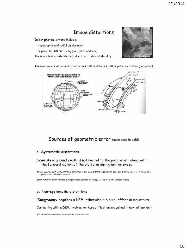
Image distortions
In air photos, errors include:
topographic and radial displacement;
airplane tip, tilt and swing (roll, pitch and yaw).
These are less in satellite data due to altitude and stability.
The main source of geometric error in satellite data is satellite path orientation (non-polar)
Sources of geometric error (main ones in bold)
a. Systematic distortions
Scan skew: ground swath is not normal to the polar axis – along with the forward motion of the platform during mirror sweep
Mirror-scan Velocity and panoramic distortion: along-scan distortion (pixels at edge are slightly larger). This would be
greater for off-nadir sensors. Earth rotation: earth rotates during scanning (offset of rows).... (122 pixels per Landsat scene)
b. Non-systematic distortions Topography: requires a DEM, otherwise ~ 6 pixel offset in mountains Correcting with a DEM involves ‘orthorectification’ (required in new millennium) Altitude and attitude variations in satellite: these are minor

2/1/2014
11
Geocorrection
Rectification – assigning coordinates to (~6) known locations - GCPs GCP = Ground Control Point
Resampling - resetting the pixels (rows and columns) to match the GCPs Orthorectification: assigns elevation (z) to each pixel as well as x and y (using a DEM)
Rectification Data pixels must be related to ground locations, e.g. in UTM coordinates Two main methods: - Image to image (to a geocorrected image) .... to an uncorrected image would be 'registration' not rectification
-Image to vectors (to a digital file).... Requires picking known locations = Ground Control Points (GCPs) These must be visible on the image e.g. road intersections, stream/lakes joining (black arrows point to known locations - coordinates from vectors or images)

2/1/2014
12
The collection of GCPs can be a problem for ortho-rectification. A source of GCPs may not be available. The process is also time-consuming and tricky. What makes RapidEye special #3: The RapidEye satellite platforms have been constructed by Surrey Satellite Technology Ltd (SSTL). Each satellite uses a star tracker known as the Altair HB. It was developed as an alternative low cost, high accuracy, spacecraft attitude determination and control sensor. The attitude information helps to orthorectify the RapidEye data to a map projection without a need for GCPs.
Projections and reprojection
Reprojecting vectors simply reassigns coordinates to points … using specified ellipsoid and projection
Reprojecting rasters involves resampling every pixel
A. nearest neighbour
B. bilinear
C. cubic convolution

2/1/2014
13
Resampling methods
http://www.geo-informatie.nl/courses/grs20306/course/Schedule/Geometric-correction-RS-new.pdf
New DN values are assigned in 3 ways a.Nearest Neighbour Pixel in new grid gets the value of closest pixel from old grid – retains original DNs b. Bilinear Interpolation New pixel gets a value from the weighted average of 4 (2 x 2) nearest pixels; smoother but ‘synthetic’ c. Cubic Convolution (smoothest) New pixel DNs are computed from weighting 16 (4 x 4) surrounding DNs
Resampling
http://www.geo-informatie.nl/courses/grs20306/course/Schedule/Geometric-correction-RS-new.pdf
Good rectification is required for image registration – no ‘movement’ between images

2/1/2014
14
Resampling – pixel size In the early days during resampling stage, pixels were rounded to match UTM grid and DEMs: Landsat MSS 80m raw pixels -> 50m corrected pixels Landsat TM 30 (28.5) m -> 25m
BC TRIM DEM was built to 25m to match Landsat TM data software now can handle different resolutions Rapideye 6.5 m -> 5 m
Now for something completely different – perfect registration needed….
100% Marilyn Monroe -> 100% Margaret Thatcher