Embed Size (px)
Citation preview
RADIOLOGICAL DOSE ASSESSMENT FOR THE
LEAKING COIL REPLACEMENT ON THE
NECSA RADIOACTIVE EFFLUENT
EVAPORATOR FACILITY
Charles Kros
A Research Report
submitted to the Faculty of Science,
University of the Witwatersrand, Johannesburg,
in partial fulfilment of the requirements for the degree of Master of Science.
School of Physics
December, 2013
ii
DECLARATION
I declare that this research report is my own, unaided work. It is being submitted
for the Degree of Master of Science in the University of the Witwatersrand,
Johannesburg. It has not been submitted before for any degree or examination in
any other university.
_______________________________________
Charles Gustav Kros
6 December 2013
iii
ABSTRACT
In this study a dose assessment is used to demonstrate conformance to national
and international dose limits for workers and meets the Necsa ALARA goals for a
radiological repair task. The dose assessment methodology is based on
international standards, principles and criteria and involves the process of
determining radiological dose, through the use of exposure scenarios, bioassay
results, monitoring data, source term information, and pathway analysis.
The radiological task is the replacement of the leaking steam coil on the
radioactive effluent evaporator facility at Necsa. The effluent treatment facility, its
operation, the origin of the radioactive effluent and hazards associated with the
leaking coil are discussed.
The dose assessment is supported by measurement of actual radiological
conditions in the area where the task will be performed using suitable and
calibrated instrumentation. The assumptions were limited to the physical
phenomena associated with the behaviour of materials and available from national
and international studies. The importance of proper planning of all the tasks
associated with the replacement task as well as sources of inaccuracy and
uncertainty associated with the calculated doses are discussed.
The results of the assessment are evaluated in terms of ALARA, namely the safety
fundamental principles of justification, optimisation and limitation of facilities
and activities. Other dose reduction options, such as personal protective clothing
and equipment, were considered to show that the doses conform to the ALARA
objectives of Necsa and other operation optimisation measures.

iv
DEDICATION
Dedicated to my loving wife, Liezl, and sons, Eric and Etienne.
v
ACKNOWLEDGEMENTS
I want to specially thank my wife, Liezl, and my two sons, Eric and Etienne, for
the many years of patience with me and this study. I trust our family will have
grown closer during this period and share in this achievement.
I want to thank the University of Witwatersrand, in particular Prof. John Carter
and Mr James Larkin for their guidance, lecturing and support during this period.
I want to thank Necsa for providing me with the opportunity to perform this study
through allowance of time and provision of funding. In particular, I want to thank
my internal supervisor and mentor, Mr Abrie Visagie, for whom I have the utmost
respect. Abrie has demonstrated, through the many years that I have known him,
the ability to disseminate his immense knowledge of radiation protection and
nuclear licensing, which provided an ideal platform for my own development in
radiation protection.
vi
TABLE OF CONTENTS
DECLARATION .............................................................................................................. ii
ABSTRACT ..................................................................................................................... iii
DEDICATION ................................................................................................................. iv
ACKNOWLEDGEMENTS .............................................................................................. v
TABLE OF CONTENTS ................................................................................................. vi
LIST OF FIGURES ......................................................................................................... ix
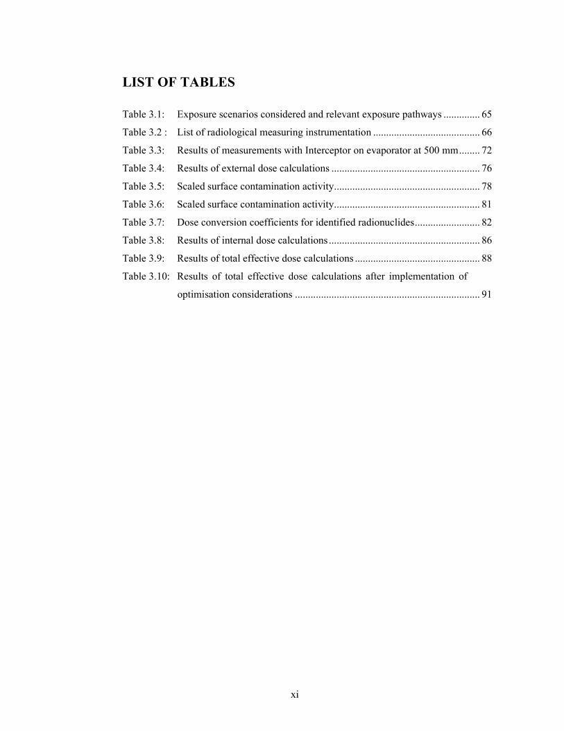
LIST OF TABLES ........................................................................................................... xi
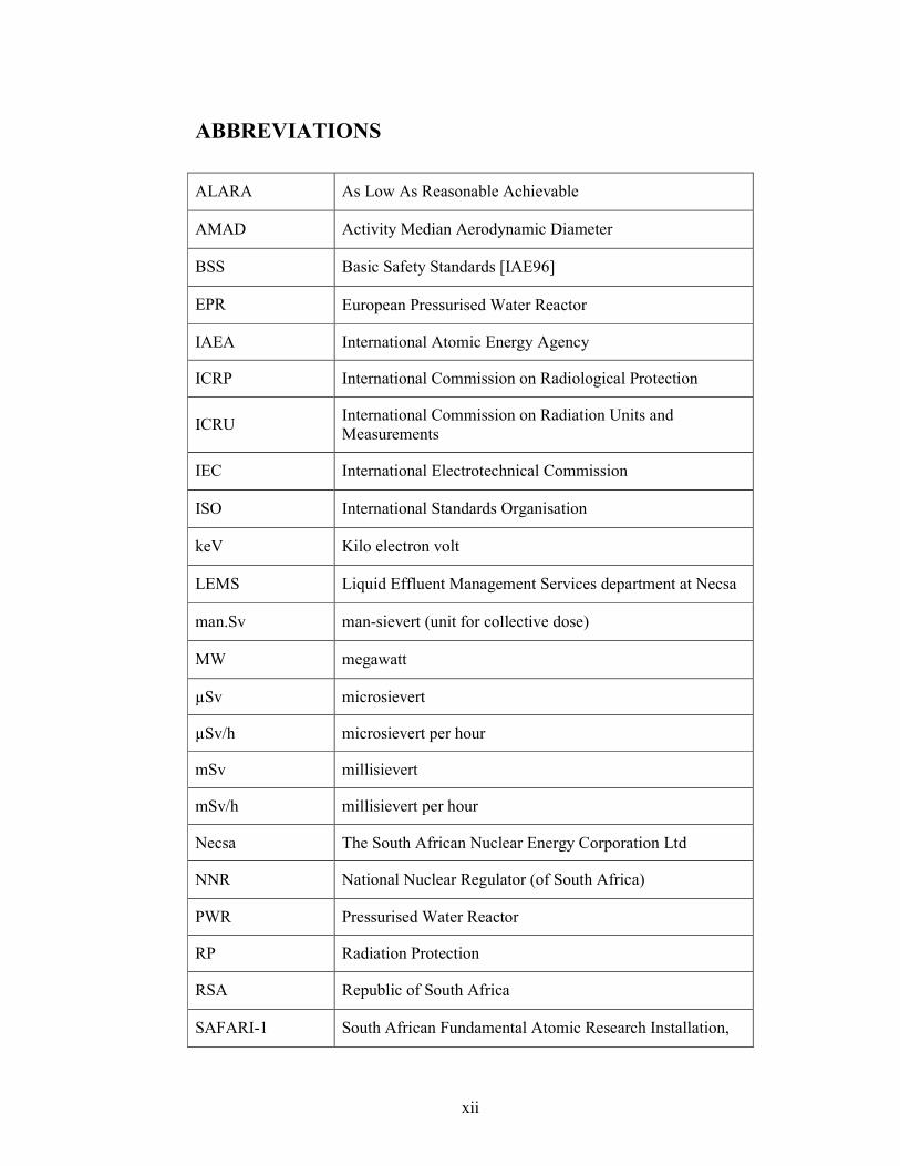
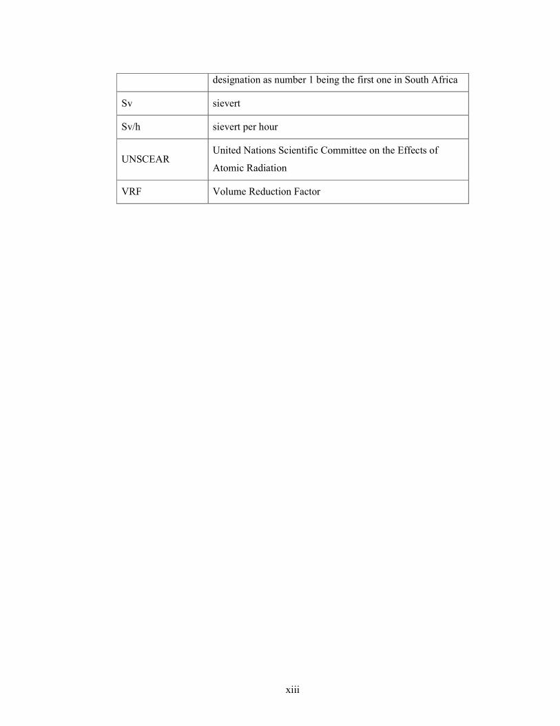
ABBREVIATIONS ........................................................................................................ xii
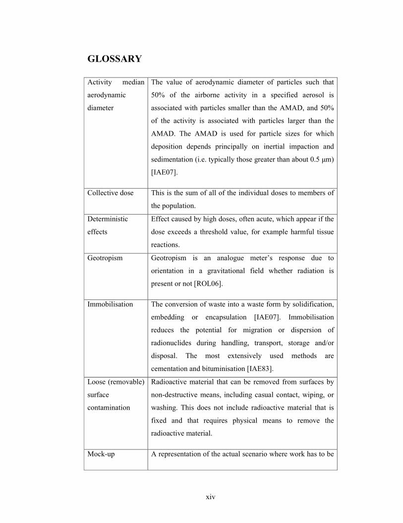
GLOSSARY ................................................................................................................... xiv
CHAPTER 1 – INTRODUCTION ................................................................................ 1
1.1 Occupational exposure of individuals ................................................................... 1
1.2 Dose assessment and ALARA .............................................................................. 1
1.2.1 Fundamental safety principles................................................................ 2
1.2.2 System of radiological protection .......................................................... 6
1.2.3 Exposure situations ................................................................................ 8
1.2.4 Dose limits ............................................................................................. 8
1.2.5 A national perspective ............................................................................ 9
1.2.6 As Low As Reasonably Achievable (ALARA) ................................... 10
1.2.7 Dose assessment ................................................................................... 12
1.2.8 Demonstrating ALARA at Necsa......................................................... 13
1.3 Statement of the problem .................................................................................... 14
1.3.1 Objective .............................................................................................. 15
1.3.2 Methodology ........................................................................................ 15
1.4 Research Report structure and chapter outline.................................................... 18
CHAPTER 2 – THEORETICAL CONSIDERATIONS ........................................... 21
2.1 Treatment of liquid radioactive waste ................................................................. 21
2.2 Liquid effluent at Necsa ...................................................................................... 22
2.2.1 Classification of radioactive liquid effluent ......................................... 22
2.2.2 Treatment of low activity effluent........................................................ 23
vii
2.2.3 Treatment of medium activity effluent ................................................ 24
2.2.4 Origin of medium activity radioactive effluent at Necsa ..................... 24
2.2.5 Treatment of medium activity effluent at Necsa .................................. 28
2.3 Problem with the Necsa evaporator .................................................................... 32
2.4 Physics of basic interactions of radiation with matter ........................................ 33
2.4.1 Overview of atomic and nuclear structure ........................................... 33
2.4.2 Radioactive decay ................................................................................ 34
2.4.3 Sources of gamma rays ........................................................................ 35
2.4.4 Basic interaction mechanisms of ionising photons with matter ........... 38
2.5 Radiation detection and measurement ................................................................ 45
2.5.1 Theory of detection and measurement ................................................. 45
2.5.2 Measurement of charged particles ....................................................... 46
2.5.3 Gamma-ray spectrometry and dose measuring instruments ................ 48
2.5.4 Energy resolution ................................................................................. 49
2.5.5 Calibration and accuracy of measurement ........................................... 50
2.6 Dose assessment methodology ............................................................................ 51
2.6.1 Exposure pathways............................................................................... 51
2.6.2 Assumptions ......................................................................................... 52
2.6.3 External dose assessment ..................................................................... 52
2.6.4 Internal dose Assessment ..................................................................... 53
2.7 ALARA and the optimisation of exposure.......................................................... 54
CHAPTER 3 – CALCULATION OF INTERNAL AND EXTERNAL DOSE
TO THE WORKERS, AND OPTIMISATION ......................................................... 57
3.1 Introduction ......................................................................................................... 57
3.2 Dose assessment methodology ............................................................................ 58
3.2.1 Principles and methodology ................................................................. 58
3.2.2 Assumptions ......................................................................................... 59
3.2.3 Total effective dose .............................................................................. 59
3.2.4 External dose assessment ..................................................................... 59
3.2.5 Internal dose assessment ...................................................................... 60
3.3 Defining the exposure scenarios ......................................................................... 62
3.4 Radiological surveillance instrumentation .......................................................... 66
viii
3.5 External dose calculation .................................................................................... 70
3.5.1 Interpretation of measurement data ...................................................... 70
3.5.2 Identification of relevant nuclides ........................................................ 71
3.5.3 Assumption used for external dose calculation .................................... 75
3.6 Internal dose calculation ..................................................................................... 77
3.6.1 Interpretation of measured data ............................................................ 77
3.6.2 Assumptions used for internal dose calculations ................................. 79
3.6.3 Results .................................................................................................. 85
3.7 Total effective dose ............................................................................................. 88
3.8 Optimisation of Exposure ................................................................................... 88
3.8.1 Further optimisation options to reduce internal exposure .................... 89
3.8.2 Further optimisation options to reduce external exposure ................... 90
3.8.3 Recommendations for radiation protection programme ...................... 92
CHAPTER 4 – CONCLUSIONS AND RECOMMENDATIONS ........................... 93
4.1 Conclusions from calculations ............................................................................ 93
4.2 Conclusions on ALARA ..................................................................................... 94
REFERENCES ................................................................................................................ 96
APPENDIX A – Analysis Report ................................................................................. 103
ix
LIST OF FIGURES
Figure 1.1: Methodology used in this research report. ................................................. 17
Figure 1.2 : Diagrammatic presentation of Chapter layouts used in this report. ........... 20
Figure 2.1: Schematic representation of medium activity effluent treatment
process, showing the SAFARI-1 reactor pool, ion exchangers and
evaporator. ................................................................................................. 29
Figure 2.2 : Photograph of the lower section of evaporator and steam coil inside
the evaporator taken by the author. ............................................................ 30
Figure 2.3 : Photograph of the upper section of the evaporator taken by the
author. ........................................................................................................ 31
Figure 2.4 : Decay scheme for gamma-ray sources [KNO10]. ..................................... 37
Figure 2.5 : Interaction of γ-ray photons with matter, showing in (a) Photoelectric
absorption, (b) Compton scattering and (c) Pair production. ..................... 40
Figure 2.6 : Relative importance of the three major types of gamma ray
interactions. Taken from [KNO10]. ........................................................... 41
Figure 2.7: Pulse-height spectrum measured wih a 4 x 4 inch NaI(Tl) crystal
scintillator exposed to gamma rays from 137
Cs. Taken from [TUR05]. .... 44
Figure 3.1 : Portable contamination monitor ................................................................. 68
Figure 3.2 : Thermo Electron Corporation’s Interceptor portable radiation
detector. ...................................................................................................... 69
Figure 3.3: Positions where dose rate measurements were performed on
evaporator. ................................................................................................. 72
Figure 3.4: Graphic of spectrum drawn with Interceptor portable radiation
detector as displayed by instrument. .......................................................... 74
Figure 3.5: Results of spectrometric analysis performed by Interceptor portable
radiation detector as displayed by instrument. ........................................... 74
Figure 3.6: Graphic showing inhalation and ingestion dose per radionuclide as a
percentage of the total committed effective dose....................................... 87
Figure 3.7 : Graphic showing internal dose per worker category.................................. 87
x
Figure 4.1: Average measurable dose per occupational worker at commercial
nuclear power reactors and other facilities in the USA, 1973-2006 in
mSv. Taken from [BLE11]. ....................................................................... 95
xi
LIST OF TABLES
Table 3.1: Exposure scenarios considered and relevant exposure pathways .............. 65
Table 3.2 : List of radiological measuring instrumentation ......................................... 66
Table 3.3: Results of measurements with Interceptor on evaporator at 500 mm ........ 72
Table 3.4: Results of external dose calculations ......................................................... 76
Table 3.5: Scaled surface contamination activity ........................................................ 78
Table 3.6: Scaled surface contamination activity ........................................................ 81
Table 3.7: Dose conversion coefficients for identified radionuclides ......................... 82
Table 3.8: Results of internal dose calculations .......................................................... 86
Table 3.9: Results of total effective dose calculations ................................................ 88
Table 3.10: Results of total effective dose calculations after implementation of
optimisation considerations ....................................................................... 91
xii
ABBREVIATIONS
ALARA As Low As Reasonable Achievable
AMAD Activity Median Aerodynamic Diameter
BSS Basic Safety Standards [IAE96]
EPR European Pressurised Water Reactor
IAEA International Atomic Energy Agency
ICRP International Commission on Radiological Protection
ICRU International Commission on Radiation Units and
Measurements
IEC International Electrotechnical Commission
ISO International Standards Organisation
keV Kilo electron volt
LEMS Liquid Effluent Management Services department at Necsa
man.Sv man-sievert (unit for collective dose)
MW megawatt
µSv microsievert
µSv/h microsievert per hour
mSv millisievert
mSv/h millisievert per hour
Necsa The South African Nuclear Energy Corporation Ltd
NNR National Nuclear Regulator (of South Africa)
PWR Pressurised Water Reactor
RP Radiation Protection
RSA Republic of South Africa
SAFARI-1 South African Fundamental Atomic Research Installation,
xiii
designation as number 1 being the first one in South Africa
Sv sievert
Sv/h sievert per hour
UNSCEAR United Nations Scientific Committee on the Effects of
Atomic Radiation
VRF Volume Reduction Factor
xiv
GLOSSARY
Activity median
aerodynamic
diameter
The value of aerodynamic diameter of particles such that
50% of the airborne activity in a specified aerosol is
associated with particles smaller than the AMAD, and 50%
of the activity is associated with particles larger than the
AMAD. The AMAD is used for particle sizes for which
deposition depends principally on inertial impaction and
sedimentation (i.e. typically those greater than about 0.5 µm)
[IAE07].
Collective dose This is the sum of all of the individual doses to members of
the population.
Deterministic
effects
Effect caused by high doses, often acute, which appear if the
dose exceeds a threshold value, for example harmful tissue
reactions.
Geotropism Geotropism is an analogue meter’s response due to
orientation in a gravitational field whether radiation is
present or not [ROL06].
Immobilisation The conversion of waste into a waste form by solidification,
embedding or encapsulation [IAE07]. Immobilisation
reduces the potential for migration or dispersion of
radionuclides during handling, transport, storage and/or
disposal. The most extensively used methods are
cementation and bituminisation [IAE83].
Loose (removable)
surface
contamination
Radioactive material that can be removed from surfaces by
non-destructive means, including casual contact, wiping, or
washing. This does not include radioactive material that is
fixed and that requires physical means to remove the
radioactive material.
Mock-up A representation of the actual scenario where work has to be
xv
performed with no radioactive material present. Typically
used for training of workers to perform a task.
Resuspension
factor
The quantitative relationship between the concentration of
loose surface contamination and consequent atmospheric
concentration above the contaminated surface [CEM09]
Stochastic effects Effects that may be caused by high or low doses which may
be observed as a statistically detectable increase in the
incidences of these effects occurring long after exposure, for
example cancer or heritable effects.
1
CHAPTER 1 – INTRODUCTION
INTRODUCTION
“Occupational exposure to ionising radiation can occur in a range of industries,
medical institutions, educational and research establishments and nuclear fuel
cycle facilities. Adequate radiation protection of workers is essential for the safe
and acceptable use of radiation, radioactive materials and nuclear energy.”
Taken from [IAE99a]
1.1 Occupational exposure of individuals
The statement above, taken from [IAE99a], required ‘adequate protection’ for
workers against the risk of ionising radiation. Before implementing such
protection measures, an assessment of the radiological hazards need to be
performed, namely a dose assessment.
Dose assessment can be defined as the process of determining radiological dose,
through the use of exposure scenarios, bioassay results, monitoring data, source
term information, and pathway analysis. These dose assessments are performed
regularly as a means of evaluating the potential, planned or subsequent dose(s)
received or to be received by personnel and/or the public from normal and
accident conditions and is a condition imposed on operators by the regulatory
authorities.
Occupational exposure is defined by the Basic Safety Standards [IAE96] as “all
exposures to workers received or committed during the course of their work, with
the exception of those exposures which are excluded or practices which are
exempted from regulations”.
1.2 Dose assessment and ALARA
"The IAEA was created in 1957 in response to the deep fears and expectations
resulting from the discovery of nuclear energy. Its fortunes are uniquely geared to
2
this controversial technology that can be used either as a weapon or as a
practical and useful tool.” [www.iaea.org]
The International Atomic Energy Agency’s (IAEA) statute authorises it “to
establish safety standards to protect health and minimise danger to life and
property” [IAE06]. Member states of the IAEA, of which South Africa has been a
member state since its creation in 1957, can then apply these safety standards by
means of regulatory provisions.
The following sections will elaborate on the fundamentals of radiological safety,
the international system employed through to national legislations and how it is
implemented at the South African Nuclear Energy Corporation Ltd (Necsa).
1.2.1 Fundamental safety principles
The IAEA has approved the publication of safety standards in the Safety
Fundamentals categories on “the safety of nuclear installations”, “safety of
radioactive waste management” and “radiation protection and the safety of
radiation sources”, respectively, between 1993 and 1995.
In 1995 the IAEA Board initiated the revision of these safety standards with the
aim of combining them in a unified set of principles to present a common safety
philosophy. In 2006, the IAEA Fundamental Safety Principles No. SF-1 [IAE06]
was approved, for promulgation by the IAEA's Board of Governors as the primary
publication in the IAEA Safety Standard Series.
The Safety Standard Series comprises the Safety Fundamentals, Safety
Requirements and Safety Guides in a tiered structure with a scientific
underpinning to support decisions concerning safety of life and property.
The Fundamental Safety Principles [IAE06] states the fundamental safety
objective and ten safety principles. The former applies to all circumstances that
give rise to any form of radiation risks. The latter applies throughout the lifetime
of all radiation facilities and activities. Facilities and activities include the safety
of nuclear facilities and any places where nuclear material is produced, processed,
3
used, handled, stored or disposed of in radiation risk scenarios where radioactive
material is produced, used, imported, exported, transported and other activities
such as decommissioning, waste management and remediation.
Fundamental safety objective
The fundamental safety objective of the IAEA reflected in this publication
[IAE06] is to protect people and the environment from the harmful effects of
ionising radiation “without unduly limiting the operation of facilities or the
conduct of activities that give rise to radiation risks”. Ten safety principles have
been formulated to achieve this objective. The ten safety principles are:
Principle 1: Responsibility for safety
The holder of an authorisation, known as the licensee, has the prime responsibility
for safety. “Safety” refers to the protection of people and the environment
according to the fundamental safety objective and includes safety under normal
operational conditions and accident conditions.
Principle 2: Role of the government
An effective legal and governmental framework for radiation safety must be
established and sustained. This should include an independent regulatory body.
This requires government to adopt within its legal framework provisions for
legislation, regulations, and other standards and measures to fulfil its national and
international obligations and to establish an independent regulatory body.
Principle 3: Leadership and management for safety
Effective leadership and management for safety matters must be established and
sustained. This applies to all organisations concerned with, and facilities and
activities that give rise to, radiation risks. This has to be demonstrated at the
highest levels in the organisations and achieved by an effective management
system. The management system also has to ensure the promotion of a safety
culture that governs the attitudes and behaviour in relation to safety of all
individuals concerned.
4
Principle 4: Justification of facilities and activities
Justification requires that the benefits that nuclear installations or other facilities
and activities yield must outweigh the radiation risks to which they give rise. An
example of this is the decision to embark on a nuclear power programme. Medical
radiation exposure of patients is a special case in that the benefit is primarily to
the patient.
Principle 5: Optimisation of protection
Optimisation is achieved when the highest level of safety can reasonably be
achieved without unduly limiting utilisation. To determine whether radiation risks
are As Low As Reasonably Achievable (ALARA), all such risks, whether arising
from normal operations or from abnormal or accident conditions, must be
assessed using a graded approach a priori and periodically reassessed, during the
lifetime of facilities and activities.
Principle 6: Limitation of risks to individuals
Measures for controlling radiation risks must ensure that no individual bears an
unacceptable risk or harm. This is achieved by the application of dose and risk
limits, supplemented by the application of the principles of Justification (Principle
4) and Optimisation (Principle 5).
Together these three principles form the basis for the system of radiation
protection which will be discussed in Section 1.2.2.
Principle 7: Protection of present and future generations
People and the environment, present and future, must be protected against
radiation risks. The potential consequences, for the present and for the future, of
current activities have to be considered in judging how adequate the measures to
control radiation risks to people and the environment are. This applies also to
radioactive waste management to avoid an undue burden on future generations.
Principle 8: Prevention of accidents
The most harmful consequences arising from facilities and activities have come
from the loss of control over nuclear reactor cores, nuclear chain reactions,
5
radioactive source or other source of radiation. Consequently, measures have to
be taken to prevent the occurrence of accidents or abnormal conditions and to
ensure that the likelihood of an accident having harmful consequences is
extremely low.
The primary means of preventing and mitigating the consequences of accidents is
through a concept called “defence in depth”. Defence in depth is the principle of
implementing a combination of a number of consecutive and independent levels
of protection which would fail independently before any harmful effects could be
caused to people or the environment. If any single level of protection were to fail,
the subsequent level of protection or barrier would be available. When properly
implemented, defence in depth ensures that no single failure, be it technical,
human or organisational, could lead to consequences with harmful effects. It will
also provide the assurance that any number of combinations of failures are of low
probability.
Principle 9: Emergency preparedness and response
The licensee, employer, regulatory body and government have to establish
arrangements for emergency preparedness and response for nuclear or radiation
emergencies at the scene, and all levels including the international level.
Consideration has to be given to all reasonably foreseeable events when
developing emergency response arrangements.
Principle 10: Protective actions to reduce existing or unregulated radiation risks
Radiation risks may arise in situations other than in facilities and activities that are
in compliance with regulatory control, such as situations or activities that were
never subject to regulatory control in the past. In such situations, if the radiation
risks are relatively high, consideration has to be given to whether protective
actions can reasonably be taken to reduce radiation exposures and to remediate
adverse conditions. The protective actions will have some foreseeable economic,
social and, possibly, environmental costs and may entail some radiation risks (e.g.
to workers carrying out these protective actions) and must be considered carefully
and be optimised and justified.
6
1.2.2 System of radiological protection
Radiological protection deals with two types of harmful effects [ICR07]:
• Deterministic effects (e.g. harmful tissue reactions) are caused by high
doses, often acute, which appear if the dose exceeds a threshold value and
• Stochastic effects (e.g. cancer or heritable effects) which may be caused by
high or low doses and may be observed as a statistically detectable
increase in the incidences of these effects occurring long after exposure.
The United Nations Scientific Committee on the Effects of Atomic Radiation
(UNCSEAR) compiles assesses and disseminates information on the health effects
of radiation and on levels of exposure to radiation from different scientific studies
and reports. The International Commission on Radiological Protection (ICRP)
uses UNSCEAR reports and other international reports to publish its
recommendations on radiation protection.
In 2007, ICRP Publication 103 entitled “The 2007 Recommendations of the
International Commission on Radiation Protection” [ICR07] was released,
formally replacing the 1990 Recommendation version of the same report.
Commonly known as the “System of Radiological Protection”, this system aims
primarily to protect human health. This is reflected in its health objectives: “to
manage and control exposures to ionising radiation so that deterministic effects
are prevented, and the risks of stochastic effects are reduced to the extent
reasonably achievable” [ICR07]. In this context, this research report provides for
several changes to tissue weighting factors and updates to the radiation detriment,
but importantly maintain the three fundamental principles of radiation protection
namely justification, optimisation and the application of dose limits.
These three fundamental principles of radiation protection and how they should be
applied in planned occupational exposure situations (see Section 1.2.3) are
discussed further.
7
Justification
The principle of justification: Any decision that alters the radiation exposure
situation should do more good than harm [ICR07].
This is in line with fundamental safety principle 4 from Section 1.2.1 and in
simple terms means that within the decision to increase or decrease levels of
radiation exposure or a risk of potential exposure, the expected change in radiation
detriment as well as other risks (e.g. costs, societal benefits) should be included.
This is also referred to as the net benefit, and is implied to yield a positive net
benefit.
Optimisation
The principle of optimisation: The likelihood of incurring exposures, the number
of people exposed, and the magnitude of their individual doses should all be kept
as low as reasonably achievable, taking into account economic and societal
factors [ICR07].
Optimisation is not minimisation of dose, but the result of a forward-looking
iterative evaluation aimed at preventing or reducing exposures under prevailing
circumstances that involves:
• evaluation of the exposure situation,
• selection of an appropriate value for the constraint or reference level,
• identification of the possible protection options,
• selection of the best option under the prevailing circumstances and
• implementation of the selected option.
Dose Limitation
The principle of dose limitation: The total dose to any individual from regulated
sources in planned exposure situations other than medical exposure of patients
should not exceed the appropriate limits recommended by the Commission
[ICR07].

8
These dose limits are determined by the regulatory body, taking account of
international recommendations, and apply to workers and members of the public
in planned exposure situations. In the Republic of South Africa (RSA) the
National Nuclear Regulator (NNR) has set and published these dose limits in the
Government Gazette [NAT99a].
1.2.3 Exposure situations
The ICRP in its Recommendations evolved from the previous process-based
protection approach using practices which add doses, and interventions that
reduce doses, by moving to an approach based on the exposure situation [ICR07].
They now use a situation-based approach to characterise the possible situation
where radiation exposure may occur as planned, emergency, and existing
exposure situations, and apply the fundamental principles of justification and
optimisation of protection to all of these situations.
The three situations are:
• planned exposure situations, which are situations involving the planned
introduction and operation of sources, which includes situations that were
previously categorised as practices,
• emergency exposure situations, which are unexpected situations such as
those that may occur during the operation of a planned situation, or from a
malicious act, requiring urgent attention and
• existing exposure situations, which are exposure situations that already
exist when a decision on control has to be taken, such as those caused by
natural background radiation.
1.2.4 Dose limits
In its new Recommendation [ICR07] the ICRP furthermore reinforce the principle
of optimisation of protection, which should be applicable in a similar way to all
exposure situations, subject to the following restrictions on individual doses and
risks:
9
• dose and risk constraints for planned exposure situations and
• reference levels for emergency and existing exposure situations.
The Recommendations also include an approach for developing a framework to
demonstrate radiological protection of the environment.
Most noteworthy is the confirmation in the Recommendations that the existing
dose limits remains unchanged as it is deemed to provide an appropriate level of
protection. For occupational exposure in planned exposure situations, the limit is
20 mSv per year, averaged over defined 5 year periods, with the further provision
that the effective dose should not exceed 50 mSv in any single year.
1.2.5 A national perspective
The National Nuclear Regulator (NNR) is the regulatory body constituted to
regulate nuclear activities in the RSA, as established by the NNR Act [NAT99b]
in 1999. The NNR published regulations on safety standards and regulatory
practices [NAT99a] in 2003 which were based on the then existing IAEA Basic
Safety Standards [IAE96] of 1996. The new recommendations of the ICRP
[ICR07] in 2007 led to the publication of a new IAEA Safety Standard [IAE11] in
2011. Several changes from the previous standard have been covered in Sections
1.2.2, 1.2.3 and 1.2.4.
The national regulations might appear outdated in terms of international standards
but remain in place until such time as a revised version is issued. Most relevant is
the fact that the dose limits remain unchanged in the recent Recommendations and
standards, as confirmed in Section 1.2.4.
The national regulations [NAT99a] in its Section 3 on Principal radiation
protection and nuclear safety requirements does cover the ten fundamental safety
principles from Section 1.2.1 and the radiation protection system from Section
1.2.2. For this work Section 3.3 of the regulations is most relevant since it
prescribes a priori safety assessment: “Measures to control the risk of nuclear
damage to individuals must be determined on the basis of a prior safety
assessment which is suitable and sufficient to identify all significant radiation
10
hazards and to evaluate the nature and expected magnitude of the associated
risks, with due regards for the dose and risk limits in Annexures 2 and 3.”
[NAT99a].
1.2.6 As Low As Reasonably Achievable (ALARA)
ALARA is defined in the IAEA Safety Glossary [IAE07] and the new Basic
Safety Standards [IAE11] under optimisation of protection and safety as:
“The process of determining what level of protection and safety makes exposures,
and the probability and magnitude of potential exposures, ‘as low as reasonably
achievable, economic and social factors being taken into account’ (ALARA), as
required by the International Commission on Radiological Protection System of
Radiological Protection.”
The concept of ALARA stems from the second principle of radiation protection
(see Section 1.2.2) namely Optimisation. Optimisation is described by Cember
[CEM09] as an operating philosophy which urges actual operational dose limits
for any radiological activity to be more restrictive than the maximum
recommended dose limit. This will require processes, equipment (such as
shielding, ventilation, etc.), and other operational factors to be designed so that
workers do not exceed the operational dose limit based on a cost-benefit analysis
to derive the optimal operational solution. For this reason the ICRP [ICR07]
recommended the use of dose constraint which is lower than the dose limits.
Demonstration of ALARA is achieved by application of a process that involves a
series of steps to ensure that doses are carefully managed throughout the work.
This does not necessarily mean that dose has been minimised, as minimising dose
in isolation could have an unreasonable impact on other key factors such as
project timescales or cost. The requirement is, therefore to minimise the overall
project risk (as far as reasonably achievable) by optimising the key elements of
dose, cost, project timescale, number of workers, environmental discharges and
conventional safety.
11
The licensee in terms of the regulations [NAT99a] must therefore be able to
demonstrate that it has:
• assessed the risk,
• estimated the detriment by means of assessment,
• performed an evaluation or cost-benefit analysis and
• taken action to avert the risk where appropriate.
The key point is to ensure that dose or risk assessment and subsequent
justification is robust enough to stand up to scrutiny and cross examination in a
Court of Law, defending recommendations and advice given.
Although the ALARA concept is sometimes misused, it usually consists of the
planned and systematic application of common sense. Reasonable measures to
reduce worker and public dose usually lead to reasonable measures to assure an
optimised process. Two specific examples are:
• to prepare for maintenance work on high dose-rate systems, it is a common
practice to train on a mock-up. This assures that the workers are near the
top of the learning curve when they have to do it for real. It is also good
practice for other reasons, since mistakes can lead to equipment damage or
worse, increased doses to personnel and
• in addition to reducing collective dose, the ALARA concept requires that
the number of individuals that are exposed be optimised. This can be
achieved by distribution of work amongst several workers but also by
ensuring that no individual is exposed unnecessarily. Experience has
shown that management will typically come to depend on a few
individuals to work on certain jobs. This is a poor practice, since
additional workers may identify ways of improving the work scope, and an
organisation often gets into troubled situations when the key employee is
unavailable.

12
ALARA should thus not be considered as a waste of resources with no benefits.
Rather, it is just one aspect of a well run and optimised facility. ALARA will be
discussed in more detail in Chapter 2.
1.2.7 Dose assessment
The IAEA in its Safety Glossary [IAE07] describes assessment as the process, and
the result, of analysing systematically and evaluating the hazards associated with
sources and practices, and associated protection and safety measures. Dose
assessment is subsequently the assessment of the dose(s) to an individual or group
of people.
Dose assessments are often referred to as the ALARA pre- and post-job studies.
The pre-job ALARA study is an evaluation of the dose(s) and the means
employed to reduce this dose(s). This task is complex since the dose is normally
determined by many factors, e.g. source term, geometry, composition,
conventional hazards, work conditions, etc. Such situation is made even more
complex when a changing and/or unknown environment is encountered, as is the
case during decommissioning or non-routine maintenance activities. In the latter
cases, several assumptions will need to be made to simulate the expected
environment using prior experience (personnel, literature, etc) or experimental
results. Later in this research report significant effort will be devoted to the
assumptions made and the rationale used in this context.
The post-task study will be the culmination of the actual measured conditions and
activities into dose(s) received, as well as a comparison against the pre-job study.
By way of example, in the design and development of the European Pressurised
Water Reactor (EPR) a large effort was made to improve the plant design with
respect to radiation protection using the experience gained during the design of
former generations of Pressurised Water Reactor (PWR) in France and Germany,
and their current operation. Keeping the radiation exposure of personnel to an
acceptable level is one of the main objectives of the EPR design. Detailed dose
assessment and improvements in the design have led to decrease the target for the
13
collective exposure from 0.75 man.Sv per year to 0.5 man.Sv per year on average
[BAU06].
1.2.8 Demonstrating ALARA at Necsa
Necsa, as a licensee of the NNR to operate various facilities on the Pelindaba site
in the Northwest Province of South Africa, is required to demonstrate compliance
to the regulations [NAT99a]. Internal procedures are compiled to govern the
operations on the Necsa site.
The limitation of doses to workers and members of the public from Necsa
operations [NEC01] are aligned with the regulations [NAT99a] and international
standards [ICR07]. As required by the regulations [NAT99a], Necsa has set its
own dose constraint as an ALARA objective to ensure that exposures are
maintained as ALARA. The Necsa ALARA objective requires that the average
annual effective dose to the occupationally exposed workforce does not exceed 4
mSv for all routine operations.
For any ad-hoc radiological task (i.e. task with radiological exposure potential for
which no standard work procedure exist, normally non-routine tasks) to be
performed, Necsa requires a radiological protection work permit to be completed
[NEC02]. The completion of the work permit entails gathering of information to
perform a dose assessment of the task and provide recommendations on radiation
protection measures to ensure doses will conform to the ALARA programme
[NEC03]. Work permits are authorised by senior RP personnel. Furthermore, if
the individual dose is estimated to exceed 1 mSv, then a formal ALARA pre-
planning and review is required. An operational constraint, known as an ALARA
goal, is also defined for such a task. This ALARA goal is a predetermined dose
and is authorised by management.
An ALARA programme [NEC03] is also in place which consists of the following
elements:
• requirements for ALARA training and orientation,
14
• planning and control over radiological tasks to track and review exposures
on a regular basis,
• design criteria for new facilities or modifications to existing facilities to
meet a set dose constraint,
• continuous dose management and optimisation by means of individual
ALARA goals and regular ALARA reviews and
• optimisation of radioactive waste mainly by waste prevention and
limitation of waste quantities generated.
Individual workers at Necsa will thus be subjected to continuous monitoring
against ALARA goals based on existing operations and experience; both of which
will undergo regular review to demonstrate compliance to dose constraints,
optimisation and continual improvement.
This study involves a dose assessment for a task which has been identified to have
potentially high doses for workers, in excess of 1 mSv. Therefore, the Necsa
approach would require formal ALARA pre-planning which is achieved by a dose
assessment which must demonstrate:
• conformability to the ALARA goal and
• exposure of workers has been optimised.
1.3 Statement of the problem
The effluent treatment plant at Necsa was constructed in the 1960’s [NEW79]. At
the time the evaporator was regarded as ‘one of the most modern in the world’
[NEW79]. For the past 50 years, the evaporation facility has been operated
virtually unaltered, which speaks a lot towards the quality of workmanship and
materials employed in its construction, as well as regular maintenance performed.
However, in early 2008, failure of the steam coil in the secondary isolated circuit
resulted in the concentrate leaking from the primary to the secondary circuit. The
secondary circuit, which is not expected to contain any radioactive material, is
15
released to the industrial effluent system which acts as a barrier system before
release to the environment, through regulated practices. The radioactive leakage
was subsequently detected in the industrial effluent before release to the
environment. More descriptive information on the system will be supplied in
Chapter 2.
Fortunately, the damage to the coil initially did not necessitate halting operations,
but adversely affected the efficiency of the process (as a result of steam leaking
into the evaporator primary circuit).
Replacement of the steam coil will require a substantial amount of work to be
performed in the evaporator room, namely Cell 4, which in itself is regarded as a
confined space. The entire area is radioactively contaminated with elevated
ambient and localised high external radiation levels. In order to confirm that
worker exposures have been optimised, justified and are within regulatory limits,
an iterative process is proposed in this research report.
1.3.1 Objective
The objectives of this study is to perform a radiological dose assessment and
evaluation of the occupational exposure to workers involved in the replacement of
a steam coil inside an evaporator used for the treatment of radioactive effluent.
This includes suggestions for improvement in the light of ALARA (pre-task) and
recommendations for radiological protection during performance of the task.
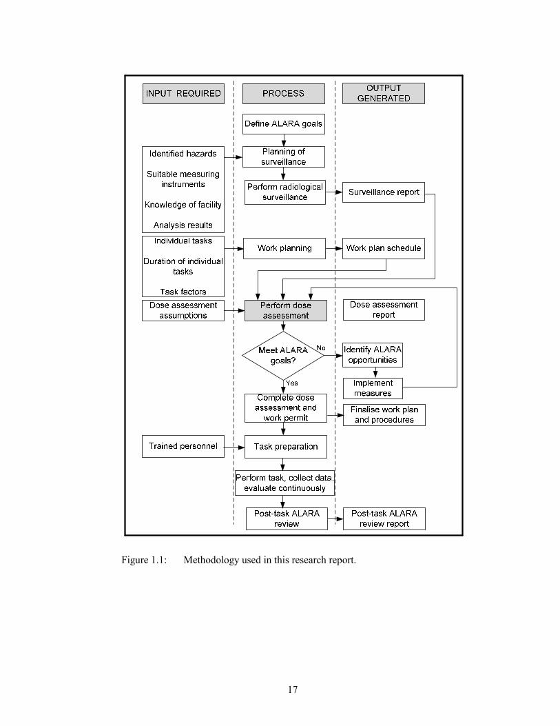
1.3.2 Methodology
The methodology is summarised in the form of a flow diagram in Figure 1.1.
The items identified in the flow chart appear in a sequential order, and are
elaborated upon below:
• Defining ALARA goals: the ALARA goal for a task needs to be set as per
Section 1.2.8.
16
• Gathering radiological information: in order to perform a dose assessment,
a radiological surveillance is required, primarily to determine the extent of
the radiological hazards as well as to perform a pre-task dose assessment
for the surveillance team.
• A detailed work plan schedule is required to perform the dose assessment.
The required information is a description of task to be performed (in
chronological order), number of persons required to perform task, names
of identified individuals and duration of task.
• Assumptions (with appropriate justifications) need to be formulated to
simulate the exposure scenarios. Examples of these assumptions are:
• air exchange rate,
• breathing rate,
• dose conversion factors and
• airborne release fractions.
• The dose assessment is performed using internationally accepted
calculation methodologies and formulae which will include the
contributions from direct external radiation, internal radiation (ingestion,
inhalation) and the total effective dose.
• Comparison with the ALARA goal: the calculated individual doses are
compared against the ALARA goal. In this work, it is expected that the
doses will exceed the ALARA goal. Based on this outcome, additional
ALARA recommendations will be made as to the measures that should be
used to decrease doses and the relative effect these will have, e.g. personal
protection clothing and equipment, area classification, access and egress,
contamination monitoring, personnel monitoring and review during the
progress.
17
Figure 1.1: Methodology used in this research report.

18
• Complete work permit: upon completion of the dose assessment and
compliance to the ALARA goal, the dose assessment is reviewed and
authorised.
• Performance of the task can commence subject to completion of task
preparations following the recommendations and provisions set, which
will include strict monitoring and record keeping.
• Post-task review: this is required as an evaluation of the effectiveness of
the measures implemented, and should include discussion on lessons
learned and suggestions for improvement in future. This is outside the
scope of this report as the author was not involved in this action.
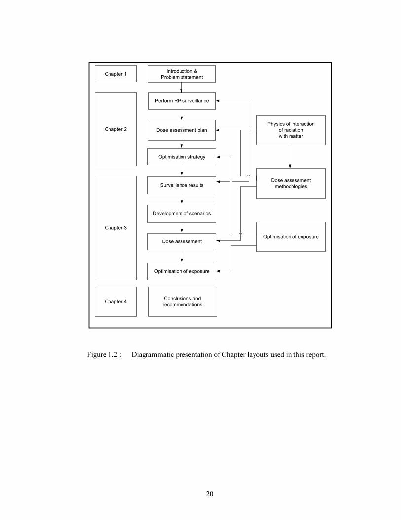
1.4 Research Report structure and chapter outline
According to the methodology described above, the layout of the study is
diagrammatically presented in Figure 1.2.
The chapter layout structure of the remaining part of the present study is as
follows:
Chapter Two – Theory part consisting of:
• background on the origin and handling of liquid effluent at Necsa,
• more background on the requirements of the dose assessment to be
performed,
• physics of interaction of radiation with matter in order to support the
measured results, derive quantitative information for the dose assessment
and identify radiological hazards,
• dose assessment methodology is expanded to cover exposure pathways
and the assessment for these pathways and
• identify ALARA options based on information gather above.
19
Chapter Three – Consisting of:
• a dose assessment using the measured data, assumptions and formulae in
Chapter 2,
• detail on the exposure scenarios,
• interpretation of the external, internal and total doses calculated and
• final radiological protection recommendations and demonstration of
compliance to ALARA constraints.
Chapter Four – Conclusions and recommendations are presented.
20
Figure 1.2 : Diagrammatic presentation of Chapter layouts used in this report.
Perform RP surveillance
Optimisation strategy
Surveillance results
Development of scenarios
Dose assessment planChapter 2
Chapter 3
Dose assessment
methodologies
Introduction &
Problem statement
Dose assessment
Optimisation of exposure
Optimisation of exposure
Physics of interaction
of radiation
with matter
Chapter 4Conclusions and
recommendations
Chapter 1
21
CHAPTER 2 – THEORETICAL CONSIDERATIONS
THEORETICAL CONSIDERATIONS
In this chapter details will be provided on the handling of liquid effluent at Necsa
and the problem with the evaporator coil which has arisen. Theory will be
provided on the physics of interaction of radiation with matter, dose assessment
methodologies and optimisation of exposure which will support the
implementation thereof in Chapter 3.
2.1 Treatment of liquid radioactive waste
The nuclear industry has been established for over six decades. Its activities give
rise to both liquid and solid wastes from various processes. In volume, liquid
wastes tend to be much greater than solid wastes [IAE84] which emphasises the
need for treatment processes which will reduce the storage capacity.
Many treatment processes exist in industry and the selection of process depends
on several factors [IAE84]:
• characteristics of the liquid wastes,
• requirements for discharge to the environment,
• available technologies and cost,
• conditioning of concentrates resulting from the treatment and
• storage and disposal of the conditioned concentrates.
The treatment processes can be categorised into 4 main categories, namely
filtration to removed suspended matter, chemical precipitation, ion exchange and
evaporation [IAE84]; however, a combination of these are normally encountered
in industry. One of the most common of these is ion exchange, which is a well
developed technique that has been employed for many years in both the nuclear
and other industries [IAE02]. All of these processes result in some form of
22
concentrate of which the most common are sludges, spent ion exchange media and
concentrates from evaporation.
The primary purpose of liquid waste treatment is to reduce the volume of the
waste. The IAEA [IAE83] defines the volume reduction factor (VRF) as follows:
.Volume of waste treated
VRFVolume of concentrate
= (2.1)
Theses concentrates require immobilisation which is defined as the conversion of
waste into a waste form by solidification, embedding or encapsulation [IAE07].
The primary purpose of immobilisation is to reduce the potential for migration,
release or dispersal of radioactive material during handling, transport, storage
and/or disposal. The most extensively used methods are cementation and
bituminisation [IAE83]. The former consists of mixing the liquid waste with
cement to form a solution within a container and allowing the mixture to set. The
latter consists of mixing the liquid waste with bitumen at elevated temperatures
which, after evaporation and cooling, results in a solidified mixture inside
containers.
2.2 Liquid effluent at Necsa
Liquid effluent in the context of the Necsa operations refer to radioactively
contaminated aqueous waste generated by the operations in nuclear facilities at
Necsa, and accepted for processing by the Liquid Effluent Management Services
(LEMS) department. Processing of liquid effluent involves different handling
operations based on classification in terms of the activity concentration of the
effluent and can included evaporation followed by solidification or even
authorised discharge to the environment.
2.2.1 Classification of radioactive liquid effluent
Liquid effluent is transferred from the generating facility to LEMS mainly by
pipeline and collected in dedicated receiving tanks. Effluent is classified [NEC04]
in terms of its activity concentration into either:
23
• low activity effluent,
• medium activity effluent or
• industrial effluent.
Low activity effluent is effluent for which the gross alpha-decay activity
concentration is between 10 and 100 Bqℓ-1
or the gross beta-decay activity is
between 40 and 4000 Bqℓ-1
. Medium activity effluent is effluent for which the
gross alpha-decay activity concentration exceeds 100 Bqℓ-1
or the gross beta-
decay activity exceeds 4000 Bqℓ-1
.
The Industrial Effluent is the type of effluent that contains low levels of
radioactivity (less than 10 Bqℓ-1
of gross alpha-decay activity or less than 40 Bqℓ-
1 of gross beta-decay activity), which requires no additional treatment and is
destined for authorised discharge into the nearby Crocodile River based on low
environmental impact.
The classification of liquid effluent in terms of activity concentration is based on
internationally accepted practice. It should be noted that the specific activity
concentrations applied at Necsa are much lower than those applied in, for
example, India [RAJ06] being due to Necsa operating a research reactor versus
the power reactors in India which operate on much higher power levels and
generate liquid effluent in larger quantities and of higher activity concentrations.
However, the treatment processes applied are similar, as mentioned in Section 2.1.
2.2.2 Treatment of low activity effluent
The low activity effluent is treated through a chemical precipitation process to
reduce the concentration of dissolved solids. Precipitate is flushed into radioactive
sludge drying beds and is treated as solid radioactive waste after drying. The Low
Activity Effluent is transferred to interim holding tanks, subjected to sampling,
radioactive analysis and discharged into the Crocodile River upon conforming to
authorised discharge criteria. The criteria are based on dose impact to the public
as set by the NNR in the regulations [NAT99a].
24
2.2.3 Treatment of medium activity effluent
Medium activity effluent cannot be discharged to the environment since its
activity is high enough to cause substantial health effects to the members of the
public. This effluent subsequently needs to be subjected to more intensive
treatment processes as discussed in Section 2.1.
The medium activity effluent treatment facility consists of receiving and storage
tanks and an evaporator system. Here, the purpose of the evaporator is to reduce
the volume of the contaminated effluent. The evaporation process results in the
activity being concentrated at the bottom of the evaporator as a condensate and the
cleaner effluent is captured at the top of the evaporator. Condensate from the
evaporator is then removed from the evaporator to separate holding tanks where,
after analysis against low activity effluent classification criteria in Section 2.2.1,
treated as low activity effluent according to Section 2.2.2.
The concentrate from the evaporator is removed at regular intervals and
immobilised as solid radioactive waste. More information will be provided in
Section 2.2.5.
2.2.4 Origin of medium activity radioactive effluent at Necsa
There are several nuclear facilities on the Necsa site, most of which generate
radioactive effluent in some form, be it from cleaning, laboratory or process
operations.
The high activity concentration in medium activity effluent is an indication that
this type of effluent is generated from specialised processes or processes where
potential for high activity levels are expected. The two facilities responsible for
the bulk of this effluent are the isotope production facility and the SAFARI-1
research reactor.

25
Isotope production facility
The isotope production facility at Necsa, operated by NTP Radioisotopes SOC
Limited, is a modern hot cell complex where radioisotopes are manufactured and
packaged. Radioisotopes are used in various chemical forms in a large number of
medical applications, such as dynamic and static diagnostic studies which include
imaging of the heart, brain, thyroid, liver, lungs, kidneys and bone.
The isotope production facility is by far Africa’s largest producer of a range of
medical isotopes that are used for diagnostic purposes and therapeutic treatment of
cancer and many millions of people have benefited from these medical isotopes.
The most important of these isotopes for Necsa, is the radioisotope Molybdenum-
99 (99
Mo) which is used extensively as a raw material for 99m
Tc (the most
important diagnostic nuclear medicine isotope).
The manufacturing process for these radionuclides involves several processing
steps which generate waste in solid, liquid or gaseous form. The liquid waste is
collected in waste storage tanks. Only when the tanks reach capacity and the
radioactivity levels has decayed sufficiently, will this effluent be transferred by
pipeline to LEMS for treatment.
SAFARI-1 research reactor
The SAFARI-1 research reactor at Necsa, constructed in the 1960s and
commissioned in 1965 [NEW79], makes use of plate type fuel elements
containing enriched uranium for operations. The enrichment grade of the uranium
was initially high enriched uranium (enriched to > 20% in the 235
U isotope) and in
2009 conversion to low enriched uranium (enriched to < 20 % in the 235
U isotope)
was completed.
SAFARI-1 is a 20 MW tank-in-pool type nuclear research reactor, owned and
operated by Necsa. SAFARI-1 is an acronym for South Africa Fundamental
Atomic Research Installation and is South Africa’s only nuclear research reactor.
26
Contamination of the primary coolant water is caused by the slow diffusion of
fission products from the fuel elements through defects in the fuel plates and by
the production of activation products. The contamination is compensated for by
removal due to radioactive decay (short lived radionuclides), deposition on the
inner surfaces of primary circuit and by decontamination of primary coolant
water. Decontamination of the primary coolant is required in order to minimise
contamination of tools and equipment, as well as to reduce exposure of personnel.
The fission process in the reactor results in the generation of a suite of fission and
activation products, as well as actinides. There are more than 40 different
elements and more than 600 different isotopes formed in the fission process.
These radioactive isotopes are produced in different quantities and possess
different physical and chemical properties, as well as biological effects. As a
result, fission products can be classified accordingly as noble gasses, halogens,
metals and actinides.
The inventory of nuclides in a reactor is mainly determined by the power level of
the reactor and the irradiation time. Short lived isotopes reach their equilibrium
concentrations soon after reactor start up while the other isotopes continue to
accumulate during irradiation. The main source of radiation in the SAFARI-1
reactor is due to the gamma radiation from these fission and activation products.
The fission inventory of reactors is available in the literature being based on
reactor power level and is normally calculated by using a computer modelling
codes (eg. ORIGEN [http://scale.ornl.gov]), as is the case for SAFARI-1. The
following represent the most important radionuclides based on activity expected:
• activation products: 54
Mn, 58
Co, 60
Co
• noble gas fission products: 133
Xe
• fission products: 90
Sr, 95
Nb, 99
Mo, 131
I, 134
Cs, 137
Cs.
Returning to the subject of decontamination of coolant water, some of the general
methods available for the treatment and decontamination of primary coolant are
chemical precipitation and ion exchange [IAE84] [RAJ06] [OHW67]. The choice
27
of a suitable technique is determined by the chemical composition of the waste
solution and by economic factors. SAFARI-1 employs mixed-bed ion exchangers
for this purpose. This is a proven technology with literature dating back to the
1950’s [NAC56] [OHW67] quoting decontamination factors of greater than 103
for mixed- bed ion exchangers.
The potential usefulness of inorganic ion-exchangers has been proven in various
areas of chemical processing before it was utilised in nuclear fuel cycle
technology, especially in the separation and fixation of fission products and
actinides and in the treatment of effluents from nuclear power plants [IAE84]. The
process involves exchange of ionic species between the liquid and solid matrix
containing ionisable polar groups. Inorganic ion-exchangers have received
attention for these purposes because of their strong chemical affinity, high
retention capacity for cation radionuclides and high resistance to radiation.
An interesting study [SIN97] has even shown this technology to be “the most
effective” for the removal of iodine from liquid effluents and for spent fuel
reprocessing [NAV89]. Studies were conducted in the 1960’s to remove
radioactive contamination from milk [EDM64] by means of an ion exchange
process. Zeolite ion exchangers were used extensively in the cleanup of large
volumes of contaminated water at Three Mile Island after the Unit 2 reactor
incident [CAM83].
The technology might be considered old, but it is still in use internationally. In
2002, the IAEA published a technical report [IAE02] where it is claimed: “With
respect to economy and efficacy, ion exchange stands between the other two
major liquid waste treatment processes of evaporation and chemical
precipitation. While evaporation may yield higher decontamination factors, it is
also more costly than ion exchange. The development of new ion exchangers is
narrowing the gap in decontamination factors between evaporation and ion
exchange.”
When the ion exchanger columns become fully loaded (saturated), they are
regenerated by using strong acids or bases, yielding high concentrations of
28
radioactive liquid waste with a high salt content. The activity concentration of this
liquid waste is typically higher than 1 MBqℓ-1
which classifies it as medium
activity effluent in terms of the criteria in Section 2.2.1. This medium activity
effluent is collected in holding tanks at SAFARI-1 before transfer to LEMS (see
Figure 2.1). SAFARI-1 is responsible for the bulk of the medium activity effluent
received by LEMS.
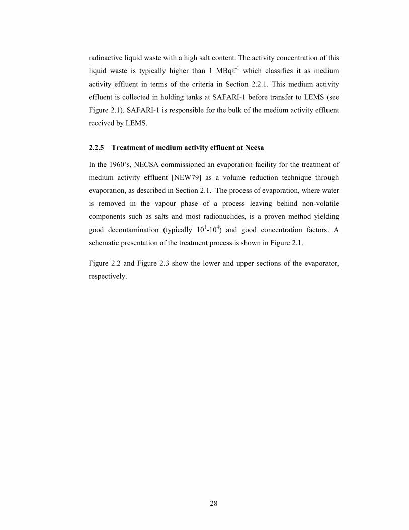
2.2.5 Treatment of medium activity effluent at Necsa
In the 1960’s, NECSA commissioned an evaporation facility for the treatment of
medium activity effluent [NEW79] as a volume reduction technique through
evaporation, as described in Section 2.1. The process of evaporation, where water
is removed in the vapour phase of a process leaving behind non-volatile
components such as salts and most radionuclides, is a proven method yielding
good decontamination (typically 101-10
4) and good concentration factors. A
schematic presentation of the treatment process is shown in Figure 2.1.
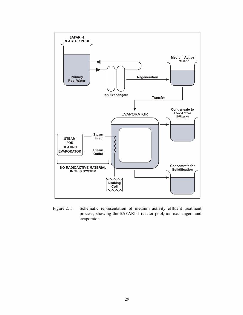
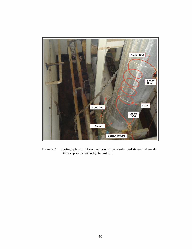
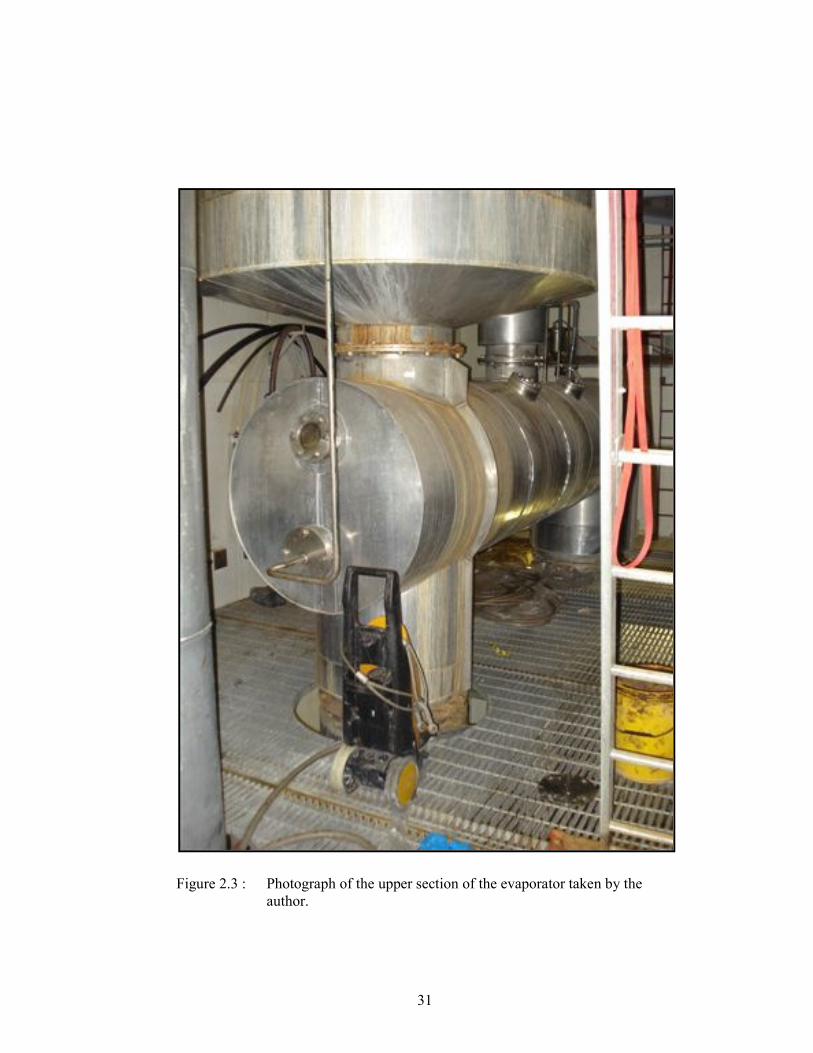
Figure 2.2 and Figure 2.3 show the lower and upper sections of the evaporator,
respectively.
29
Figure 2.1: Schematic representation of medium activity effluent treatment
process, showing the SAFARI-1 reactor pool, ion exchangers and
evaporator.
30
Figure 2.2 : Photograph of the lower section of evaporator and steam coil inside
the evaporator taken by the author.
31
Figure 2.3 : Photograph of the upper section of the evaporator taken by the
author.
32
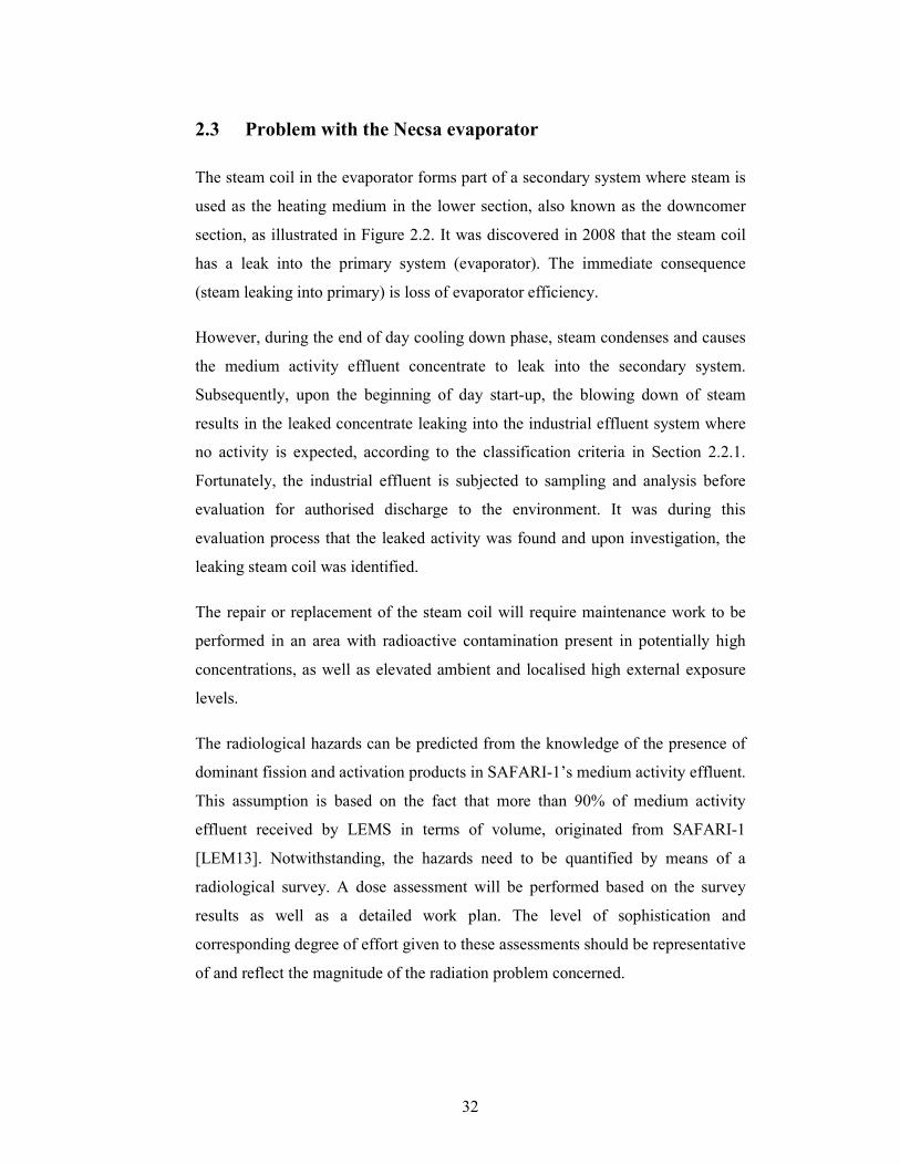
2.3 Problem with the Necsa evaporator
The steam coil in the evaporator forms part of a secondary system where steam is
used as the heating medium in the lower section, also known as the downcomer
section, as illustrated in Figure 2.2. It was discovered in 2008 that the steam coil
has a leak into the primary system (evaporator). The immediate consequence
(steam leaking into primary) is loss of evaporator efficiency.
However, during the end of day cooling down phase, steam condenses and causes
the medium activity effluent concentrate to leak into the secondary system.
Subsequently, upon the beginning of day start-up, the blowing down of steam
results in the leaked concentrate leaking into the industrial effluent system where
no activity is expected, according to the classification criteria in Section 2.2.1.
Fortunately, the industrial effluent is subjected to sampling and analysis before
evaluation for authorised discharge to the environment. It was during this
evaluation process that the leaked activity was found and upon investigation, the
leaking steam coil was identified.
The repair or replacement of the steam coil will require maintenance work to be
performed in an area with radioactive contamination present in potentially high
concentrations, as well as elevated ambient and localised high external exposure
levels.
The radiological hazards can be predicted from the knowledge of the presence of
dominant fission and activation products in SAFARI-1’s medium activity effluent.
This assumption is based on the fact that more than 90% of medium activity
effluent received by LEMS in terms of volume, originated from SAFARI-1
[LEM13]. Notwithstanding, the hazards need to be quantified by means of a
radiological survey. A dose assessment will be performed based on the survey
results as well as a detailed work plan. The level of sophistication and
corresponding degree of effort given to these assessments should be representative
of and reflect the magnitude of the radiation problem concerned.
33
It is expected that the individual doses from external and internal (ingestion and
inhalation) exposure will exceed 1 mSv and that an ALARA review would be
required, as per Section 1.2.8. Such review needs to be performed to define,
quantify and implement additional engineering, administration and RP measures
in order to reduce and optimise the individual doses to acceptable levels.
Furthermore, an individual ALARA goal for this task has been set at 2.5 mSv.
2.4 Physics of basic interactions of radiation with matter
This section provides an overview of the basic interactions of radiation with
matter to obtain a better understanding in the sections which follow in this work in
order to perform a dose assessment.
2.4.1 Overview of atomic and nuclear structure
Rutherford postulated, in 1911, that a nuclear atom consists of a heavy nucleus
and negatively charged electrons situated around it and proved this
experimentally. The nucleus was conceptualised as being composed of positively
charged protons and sufficient equally-charged negative electrons. In 1913, Bohr
postulated an atomic model where the orbiting electrons move in different orbits
with varying energy levels. Bohr’s atomic model ultimately led to the construction
of the periodic table of elements [CEM09].
Ninety-two naturally occurring elements exists in nature with uranium having the
highest atomic number (Z = 92). Elements with higher atomic numbers can be
produced artificially. If the same element has different number of neutrons, it is
called an isotope of the original element. Most elements contain several isotopes
which can be stable or unstable. Unstable isotopes will spontaneously undergo
radioactive decay to become stable.
According to Bohr’s model, electrons move in orbits around the nucleus and at
different energy levels. The electrons in the inner orbits require more energy to be
removed than electrons in the outer orbits. The process of removing electrons
from its orbits is called ionisation and the energy required to achieve this is called
the ionisation energy, or the binding energy of the electron. By removing one of
34
the outmost electrons completely, the atom is “ionised” which results in one free
electron leaving the original atom slightly different in mass but with a net positive
charge.
2.4.2 Radioactive decay
It was already stated above that unstable isotopes will undergo radioactive decay
in order to reach a lower energy state. Radioactive decay will result in ‘radiation’
emitted by the atom and the result will be a new atom, called the “daughter
product”.
The decay processes of interest are alpha decay, isobaric transitions (where the
atomic mass number of the parent and daughter is the same) and isomeric
transitions (where the atomic number of the parent and daughter is the same). The
processes are discussed individually below with focus on the latter process as it is
of interest for this work.
Alpha decay
An alpha particle is a highly energetic positively charged helium nucleus that is
emitted from the nucleus of an unstable atom when the proton-to-neutron ratio is
too high.
Isobaric transitions
There are three common forms of beta decay:
• β--decay or beta emission is spontaneously produced in the nucleus by the
transformation of a neutron into a proton and a single negative electrically
charged particle (identical to an electron) and an anti-neutrino; and is
ejected from the nucleus of the atom at very high speed according to the
equation:
1 1 0
0 1 1n H + e +
υ−
→
, (2.2)
where υ is the anti-neutrino;
35
• β+-decay or positron emission is the transformation of a proton into a
neutron and a single positive electrically charged beta particle is emitted
from the nucleus of the atom; and a neutrino; according to the equation:
1 1 0
1 0 1H n + e +
υ+
→
, (2.3)
where υ is the neutrino;
• Electron Capture (EC) where the nucleus of the atom captures one of its
own orbital electrons to cause the transition of an atomic proton into a
neutron and the emission of characteristic X-rays of the daughter.
Isomeric transitions
The two forms of isomeric transitions are:
• Gamma rays are characteristic electromagnetic radiation which are emitted
from the nucleus when the excitation energy of the nucleus is released; and
• Internal conversion is a process whereby an excited nucleus of a gamma
emitting atom may rid itself of excitation energy resulting in the emission
of characteristic X-rays and Auger electrons.
2.4.3 Sources of gamma rays
The gamma decay process is the most prominent decay process of interest to the
treatment of liquid effluent in the evaporator at LEMS and the dose assessment
which follows in this work. An understanding of the sources of radiation is
therefore required.
Gamma rays following beta decay
As discussed in Section 2.4.2, beta decay can lead to some form of de-excitation
by the daughter nucleus through the emission of a gamma-ray photon whose
energy is essentially equal to the difference in energy between the initial and final

36
nuclear states. Examples of these are gamma-ray calibration sources used for
instrument calibrations such as 137
Cs and 60
Co as shown in Figure 2.4.
Annihilation radiation
When the parent nucleus undergoes β+ decay and this positron combines with a
normal negative electron in an absorbing material, then both disappear and are
replaced by two oppositely directed 0.511 MeV electromagnetic photons known
as annihilation radiation. By way of example, the decay of 22
Na to 22
Ne is also
shown in Figure 2.4.
Gamma rays following nuclear reactions
The result of nuclear reactions, such as the absorption of thermal neutrons by
typical nuclei, can result in the production of characteristic gamma rays. This
practice is used in nuclear reactors or extensively in industry to fabricate
radioactive sources.
Bremsstrahlung
When fast electrons interact in matter, part of their energy is converted into
electromagnetic radiation in the form of Bremsstrahlung. This process is of
importance for the production of X-rays from conventional X-ray tubes.
Characteristic X-rays
The process of internal conversion which causes the characteristic X-rays within
atoms was discussed in Section 2.4.2.

37
Figure 2.4 : Decay scheme for gamma-ray sources [KNO10].
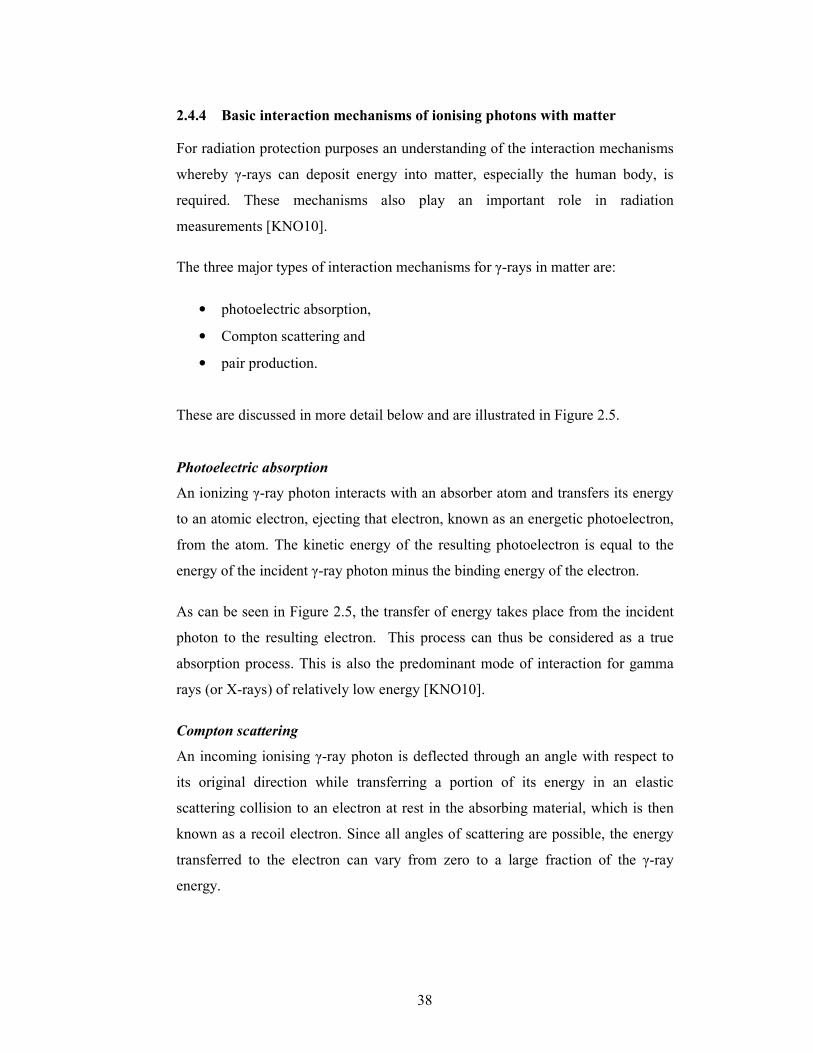
38
2.4.4 Basic interaction mechanisms of ionising photons with matter
For radiation protection purposes an understanding of the interaction mechanisms
whereby γ-rays can deposit energy into matter, especially the human body, is
required. These mechanisms also play an important role in radiation
measurements [KNO10].
The three major types of interaction mechanisms for γ-rays in matter are:
• photoelectric absorption,
• Compton scattering and
• pair production.
These are discussed in more detail below and are illustrated in Figure 2.5.
Photoelectric absorption
An ionizing γ-ray photon interacts with an absorber atom and transfers its energy
to an atomic electron, ejecting that electron, known as an energetic photoelectron,
from the atom. The kinetic energy of the resulting photoelectron is equal to the
energy of the incident γ-ray photon minus the binding energy of the electron.
As can be seen in Figure 2.5, the transfer of energy takes place from the incident
photon to the resulting electron. This process can thus be considered as a true
absorption process. This is also the predominant mode of interaction for gamma
rays (or X-rays) of relatively low energy [KNO10].
Compton scattering
An incoming ionising γ-ray photon is deflected through an angle with respect to
its original direction while transferring a portion of its energy in an elastic
scattering collision to an electron at rest in the absorbing material, which is then
known as a recoil electron. Since all angles of scattering are possible, the energy
transferred to the electron can vary from zero to a large fraction of the γ-ray
energy.
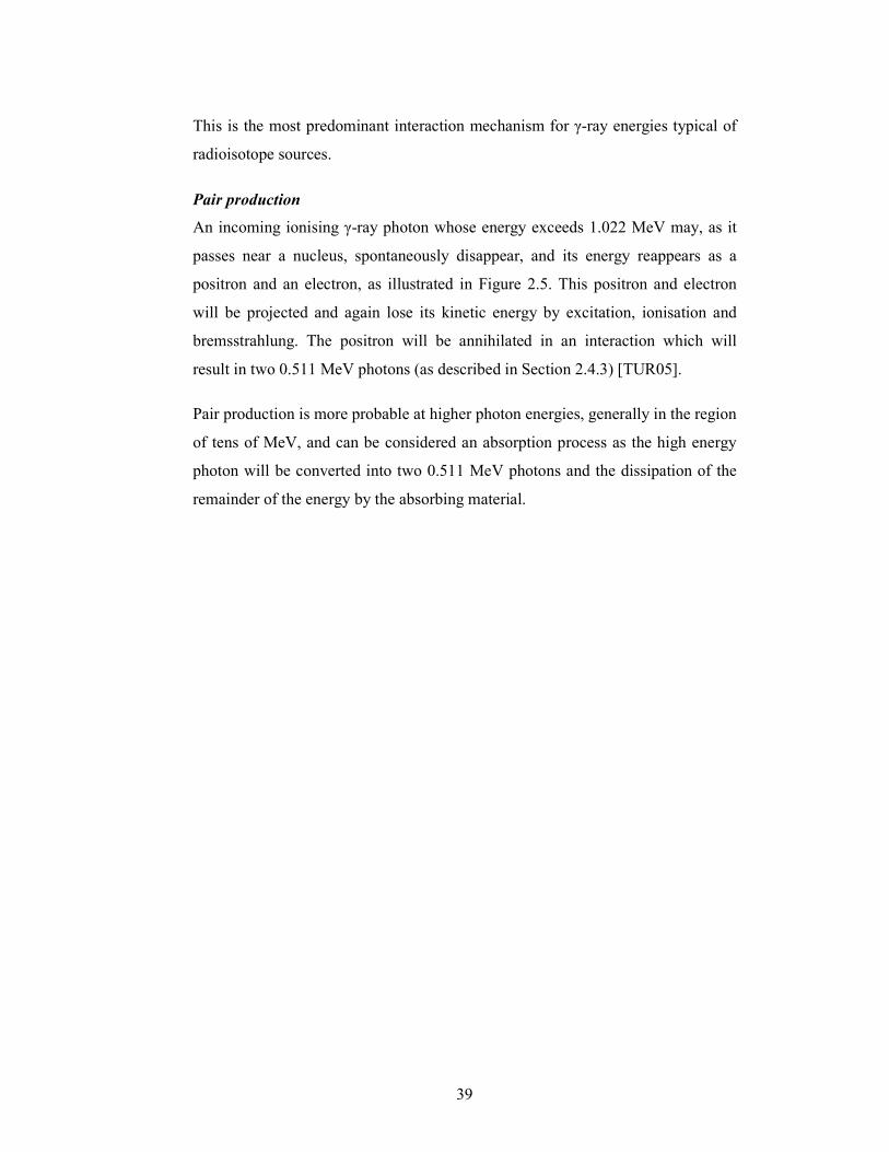
39
This is the most predominant interaction mechanism for γ-ray energies typical of
radioisotope sources.
Pair production
An incoming ionising γ-ray photon whose energy exceeds 1.022 MeV may, as it
passes near a nucleus, spontaneously disappear, and its energy reappears as a
positron and an electron, as illustrated in Figure 2.5. This positron and electron
will be projected and again lose its kinetic energy by excitation, ionisation and
bremsstrahlung. The positron will be annihilated in an interaction which will
result in two 0.511 MeV photons (as described in Section 2.4.3) [TUR05].
Pair production is more probable at higher photon energies, generally in the region
of tens of MeV, and can be considered an absorption process as the high energy
photon will be converted into two 0.511 MeV photons and the dissipation of the
remainder of the energy by the absorbing material.
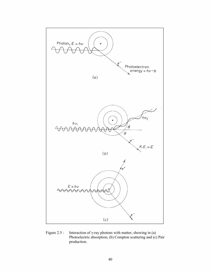
40
Figure 2.5 : Interaction of γ-ray photons with matter, showing in (a)
Photoelectric absorption, (b) Compton scattering and (c) Pair
production.
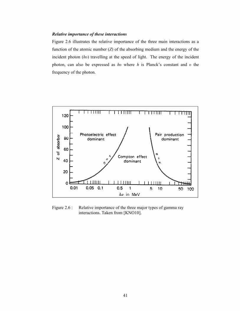
41
Relative importance of these interactions
Figure 2.6 illustrates the relative importance of the three main interactions as a
function of the atomic number (Z) of the absorbing medium and the energy of the
incident photon (hυ) travelling at the speed of light. The energy of the incident
photon, can also be expressed as hυ where h is Planck’s constant and υ the
frequency of the photon.
Figure 2.6 : Relative importance of the three major types of gamma ray
interactions. Taken from [KNO10].
42
The three photon interactions allow for the interpretation of a number of
properties of pulse-height spectra, as presented by J.E. Turner [TUR05]. This is
illustrated in Figure 2.7 for the spectra from a 137
Cs gamma ray source with a
gamma ray energy of 662 keV. The photons are actually released by the transition
of the metastable (half-life 2.55 min) 137m
Ba daughter nucleus of 137
Cs to its
ground state. The data in Figure 2.7 were collected with a 4 x 4 inch NaI(T1)
crystal.
As discussed above, the transfer of energy normally occurs in one of two ways:
• a primary photon is absorbed (photoelectric absorption), and the
photoelectron, Auger electrons, and fluorescence radiation are all
absorbed in the crystal, or
• an incident photon that is Compton scattered one or more times is
absorbed in the crystal.
The large narrow peak shown in Figure 2.7, known as the total energy peak in
scintillation spectrometry, is due photoelectric absorption where the pulses are
caused whenever the entire energy of an incident photon is absorbed in the crystal.
The pulse is registered in the vicinity of 662 keV, which was expected and this
also confirms that photoelectric absorption is an ideal process for measuring the
energy of gamma rays.
The height of the pulse is a measure of the intensity of the energy and the spread
of the width is a measure of statistical fluctuations in the conversion of the
absorbed radiation energy into the number of electrons in the external circuit that
registers the pulse. The combination of these is known as the energy resolution
which is a measure of the effectiveness of the device and is discussed in Section
2.5.4.
The Compton edge, shown in Figure 2.7 at 478 keV, represents the maximum
energy that an electron can acquire from Compton scattering by a primary photon.
43
Another characteristic feature of the spectrum in Figure 2.7 is the lower and wider
part of the curve, known as the Compton scattering curve. This curve represents a
continuum of pulses, mostly from single or multiple scatterings ranging from the
most energetic electrons to electrons due to scattering through very small angles.
The backscatter peak, shown at 187 keV in Figure 2.7, is caused from photons that
are scattered into the scintillator from the surrounding neighbourhood and not
from directly incident primary photons. These photons have been scattered mainly
through large angles.
The size of the detector influences the prevalence of these effects. For example,
the larger the detector, the more effective it captures the total energy of an
incident photon, subsequently reducing the contribution of the continuum and
increasing the relative size of the peak [TUR05]. The above effects are often
masked by the finite energy resolution of the detector.
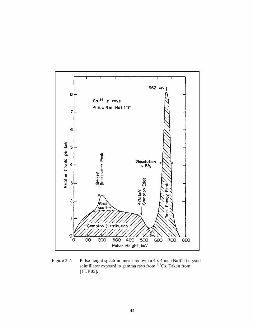
44
Figure 2.7: Pulse-height spectrum measured wih a 4 x 4 inch NaI(Tl) crystal
scintillator exposed to gamma rays from 137
Cs. Taken from
[TUR05].
45
2.5 Radiation detection and measurement
The physics presented in the preceding section serves as an aid in the
understanding of the detection principles applicable.
2.5.1 Theory of detection and measurement
Radiation detection and measurement instrumentation in radiation protection
includes a wide variety of applications, such as personnel monitoring,
environmental monitoring or contamination measurements. This section will
provide a broad overview of the theory of detection and measurement while the
following section will focus on the instrumentation required for this work.
The principle of detection relies on one or more of the interactions discussed in
Section 2.4.4 taking place inside a detector to create a charge within the electrical
field of the detector. This charge is collected to form an electrical signal which is
relayed to an electrical or mechanical device which is able to interpret it into some
useful format.
Technological developments in the areas of material science, electronics, and
computer technology have resulted in more sensitive, affordable, reliable, and user
friendly instruments. This section will focus on two radiation measurement
systems used in this work, namely:
• charged particle measuring instruments (subdivided into gas-filled
counters and scintillation counters) and
• gamma-ray measuring instruments.
These systems provide the capability to measure, quantify and identify most forms
of radiation from alpha-decay, beta-decay and gamma photons, respectively.
Since neutrons are outside the scope of this work, the measurement of neutrons
will not be discussed.
46
2.5.2 Measurement of charged particles
The most common charged particles for radiation protection measurements are β-
particles (negative electrons, β--particles) and alpha particles (which consist of
two protons and two neutrons, the nucleus of a 4He atom).
One important distinction between electrons emitted from the nucleus and alpha
particles, which will contribute towards the capability to measure and identify
particles, is the energy distribution of the charged particles emitted during the
decay process. The energy from electrons is distributed over an energy continuum
ranging from almost 0 eV to some maximum energy, usually referred to as Emax.
The value for Emax from a beta energy spectrum could potentially be used to
identify a radionuclide. In practice, with current instrumentation, it is difficult to
get an accurate enough measurement of Emax to be used for conclusive
identification. The contrary exist for alpha particles which are emitted at discrete
energies. These energies are used in practice for identification purposes as they
are characteristic of the parent radionuclide.
The detector in particle-counting instruments may be either a gas or a solid. In
either case, the passage of an ionising particle through the detector results in
energy dissipation by a burst of ionisation which is converted into an electrical
pulse that actuates a readout device.
Gas-filled particle counters are all of similar design. There are three basic types
of gas-filled detectors:
• ionisation chamber,
• proportional counter and
• Geiger-Müller counter.
They all operate on similar way but use different types of gases. Each has their
own advantages and disadvantages in terms of size, operational costs and
detection efficiencies. The selection of an operating voltage is critical for proper
operation of a gas-filled counter.
47
In this work, a gas-flow proportional counter was used to measure the removable
surface contamination on smear samples. Gas-flow proportional counters are
operated at a bias voltage of normally ~ 600-800 V. The selection of voltage is
important as the size of the output pulse is proportional to the high voltage across
the detector. The correct voltage will ensure that only alpha particles are detected,
commonly referred to as “alpha only” mode. If the bias voltage is increased to
normally ~1500 V the counter will respond to both alpha and beta particles.
Operation at this higher voltage is referred to as “simultaneous” or “α + β” mode.
Beta particles are more penetrating than alpha particles and are less affected by
mass absorption. Beta particles have the ability to escape the active volume of a
gas-flow proportional counter before all the energy from the β-particle is
deposited within the detector and there is a higher probability of backscatter with
beta particles which, depending upon the source backing material, can have a
significant impact on the overall counting response with a proportional counter.
The counting response is also dependent on the energy distribution of beta
emissions and the interactions of the beta particles with the counting gas. Typical
beta counting efficiencies of windowless gas-flow proportional counters are in the
range 50-90%. The beta counting efficiency is a function of the average beta-
decay energy which means there is no single beta counting efficiency to use for
the calculation of the gross beta activity. In the calibration of these instruments,
the beta efficiency for gross beta-decay measurements is determined with a
standard reference material source prepared from 90
Sr (mean energy of 0.546
MeV) in secular equilibrium with its daughter 90
Y (mean energy of 2.281 MeV)
[ICR08].
The alpha counting efficiency is fairly constant over the range of 4 to 6 MeV. For
this reason and the fact that alpha particles are emitted at discrete energies, the
alpha counting efficiency is normally determined with 241
Am which has a mean
alpha-decay energy of 5.479 MeV [ICR08].
Samples in the form of smears taken from surfaces are counted in the gas-filled
detectors to determine the gross alpha-decay and gross beta-decay activities.
48
Another type of instrument to measure charge particles is the scintillation counter.
As the name implies, the detector makes use of a transducer that changes the
kinetic energy of an ionising particle into a flash of light. This light is viewed by
photomultiplier tubes or photodiodes whose output is interpreted and counted.
Scintillation counters are used extensively to count alpha and beta particles and
gamma rays. Since the intensity of the light pulse is proportional to the energy of
the particle, distinction can be made between alpha particles of higher energy and
beta particles of lower energy by means of discrimination of the pulse height of
the electronic signal.
For radiation protection usage, scintillation counters have been developed which
can be used as portable and battery powered instrumentation. These are relatively
inexpensive to maintain except for the thin foil used to cover the outer surface of
the scintillator. The purpose of this foil is to keep external light from entering the
detector enclosure yet thin enough not to attenuate too much of the lower energy
particles. This foil subsequently can become damaged fairly easily and requires
replacement.
2.5.3 Gamma-ray spectrometry and dose measuring instruments
The gamma-ray measuring instrumentation used in this work is confined to
instruments used in the surveillance of the work area. Subsequently, this work
does not include instruments used to measure personal dose such as dosimeters.
For this work, gamma-ray instruments were used to perform radionuclide
identification and to measure dose rate.
Scintillation detectors, similar to the technology discussed previously, can be used
for the measurement of gamma rays as well. The proportionality of the light signal
to the energy of the incident gamma rays, provided the capability to develop a
practical detector that has a high efficiency for the detection of gamma rays and,
at the same time, capable of sufficiently good energy resolution to be useful in
separating the contributions of polyenergetic gamma-ray sources [KNO10]. All
three of the interaction mechanisms in Section 2.4.4 play a role in the selection of
suitable materials to construct scintillation detectors.
49
Crystalline sodium iodide, in which a trace of thallium iodide has been added in
the melt, is commonly known as NaI(Tl) and remains the most common choice
for detector material because of its exceptionally large scintillation light output,
relatively low production cost and excellent efficiency. However, poor energy
resolution makes it less ideal for complex spectra analysis applications. It is most
commonly used for simple spectra or online monitoring systems.
The most popular type of scintillation detector currently used for gamma-ray
spectrometry in laboratory conditions, and used in this work, is the coaxial high-
purity germanium (HPGe) detector. HPGe detectors provide excellent energy
resolution but must be kept at low temperatures, typically 77 K, by using liquid
nitrogen to maintain such good resolution.
Semiconductor diode detectors provide a more modern technology which has
great benefit, particularly in reducing the size of detectors and in relatively fast
timing characteristics. Semiconductor detectors act as a solid-state ionisation
chamber [CEM09]. The ionising gamma ray interacts with atoms in the sensitive
volume of the detector to produce electrons by ionisation which are collected and
converted to an output pulse.
2.5.4 Energy resolution
The energy resolution is a very important aspect in the spectrometry for the
interpretation of complex spectra and radionuclide identification. Knoll provides a
definition for energy resolution as [KNO10]:
0
FWHMR
H= , (2.4)
where
R = energy resolution expressed as a percentage,
FWHM = full width at half maximum of the full-energy peak and
H0 = mean pulse height corresponding to the same peak
50
It is assumed that background noise has been subtracted from the observed signal.
A scintillation detector has an energy resolution of 3-10%. The lower this
percentage, the better the detector will be at distinguishing between two energy
peaks whose energies lie near each other.
2.5.5 Calibration and accuracy of measurement
Calibration can be defined as the process of exposing an instrument in a known
exposure field and comparing the instrument reading to these know field values
[CEM09], often by means of a calibration factor or curve on a calibration
certificate. The principle of calibration requires the metrologist to determine the
instrument deviation (or error) from the known value and to perform adjustment if
these deviations are outside acceptable limits. Acceptable limits for instrument
deviation are provided by the International Electrotechnical Commission (IEC) for
many types of instruments in different applications.
Reference radiation fields for calibration and routine testing of instruments are
recommended by the International Standards Organisation (ISO) in their
standards. Portable radiation monitors, for example, must be calibrated to
determine the instrument linearity using a 137
Cs gamma-ray source and the
instrument response to different gamma-ray energies should be determined against
a 241
Am and 60
Co gamma-ray sources.
The assessment of uncertainty in measurement is the basis for quantifying the
measurement accuracy as well as an essential aspect of quality assurance. In
practice, radiation protection operators rarely perform a series of measurements to
perform any form of uncertainty evaluation. Much reliance is placed on the ICRU
recommendation [ICR93] for single measurements that "....in most cases, an
overall uncertainty of one standard deviation of 30% should be acceptable."
The situation is further complicated by several influencing factors, such as the
different radiation energies or the instrument angular response. For this study, all
measurements were well above background levels which also reduce uncertainties
considerably.
51
2.6 Dose assessment methodology
The IAEA Safety Guide on Occupational Radiation Protection [IAE99a]
recommends the prior radiological evaluation to include:
• an identification of the sources of routine and reasonably foreseen
potential exposures,
• a realistic estimate of the relevant doses and probabilities and
• an identification of the radiological protection measures to meet the
optimisation principle.
The initial step is commonly referred to as “characterisation” [LAB07] which
includes in situ measurements of radiological conditions.
Literature on dose assessment also suggests emerging radiological protection
challenges to arise in the near future. One such recent paper by Lazo [LAZ11]
elaborates on the possibility of “individual-level risk assessment” based on the
ICRP developing male, female, child and infant phantoms. This challenges the
current “one-size-fits-all” approach to exposure management for gender- and age-
averaged individuals.
2.6.1 Exposure pathways
Numerous exposure pathways have been identified and considered to calculate the
radiological exposure of individuals. For occupational exposure the most
significant exposure pathways involve external exposure due to penetrating
radiation and internal exposure due to inhalation or ingestion of radioactive
materials. Other exposure pathways, such as internal exposure due to
contamination of wounds and dermal absorption, do exist but is normally not
considered for normal exposure scenarios. These pathways are either
representative of abnormal situations or of very low consequence and are
generally ignored for the purpose of normal operation exposure scenarios.
52
External exposure pathways are normally the dominant pathway for a wide variety
of beta-gamma emitting radionuclides. Internal exposure due to the inhalation of
airborne radioactive material is typically an important exposure pathway for alpha
emitting radionuclides. Internal exposure due to the ingestion of radioactive
material is generally considered for scenarios where transfer of contamination
from hands to mouth can occur or where contaminated foodstuffs are ingested.
Ingestion pathways are typically important for relatively soluble beta emitting
radionuclides.
In this work, the identified exposure scenarios are:
• external exposure pathway due to gamma emitting radiation and
• internal exposure pathway due to ingestion and inhalation of contaminated
material.
2.6.2 Assumptions
The IAEA Safety Guide [IAE99a] requires the prior dose assessment to describe
the situation “as precisely as necessary”. For typical routine maintenance tasks,
the situation is well defined and performed on a regular basis which allows for an
iterative process of assessment and monitoring to ensure optimisation of exposure.
This is not the case for ad-hoc type situations where information is vague and
sometimes unpredictable.
To enable the analyst to perform a dose assessment in the absence of complete
information on the situation, the analyst will need to make assumptions. These
assumptions can be based on external consultancy, literature or even prior
experience. Examples of such assumptions are the percentage of contaminated
material which will be suspended into the air due to the maintenance activities.
These assumptions will be provided and substantiated in Chapter 3.
2.6.3 External dose assessment
External radiation in the workplace is measured in the operational quantity
ambient dose equivalent rate H*(10) for strongly penetrating radiation and
53
H*(0.07) for weakly penetrating radiation [IAE99a]. The operational quantity for
individual monitoring, recommended in the BSS, is the personal dose equivalent
Hp(10) for deeply penetrating and Hp(0.07) for weekly penetrating radiation
respectively. By using the operational quantities H*(10) or Hp(10), one obtains
approximate values for effective dose. It should be noted that these are operational
quantities for practical use in radiological protection introduced by the ICRU
[ICR93].
Instrumentation to measure ambient dose equivalent rate or personal dose
equivalent rate, is calibrated to perform this function. The results of such
measurements are used to calculate the exposure of workers to external radiation.
The external exposure of workers is dependent on several variables which need to
be defined in the exposure scenario. The variables are:
• prevailing ambient dose rate where the work is to be performed including
the type and uniformity of the radiation field,
• geometry of the radiation source including distance between source and
the worker and
• duration of work to be performed.
This will be applied in the assessment in Chapter 3.
2.6.4 Internal dose Assessment
Internal exposure of workers occurs when radioactive material is taken into the
body by inhalation, ingestion or through the skin [IAE99c]. For occupational
exposure of workers, the ICRP has developed models for describing the behaviour
of radionuclides that enter the body either by inhalation or ingestion. For exposure
pathways through the skin or open wounds, exposure is only likely to occur as a
result of accidents. Except for tritium, which is readily absorbed through the skin,
no internationally accepted models have therefore been developed for these
exposure scenarios [IAE04].
54
To perform a prospective dose assessment for internal exposure information
regarding the prevailing radiological conditions and radionuclides involved are
required. The internal exposure of workers is dependent on several variables
which need to be defined in the exposure scenario. The variables are:
• physical condition of the material to be handled (particle size
distribution, loose contamination) and work to be performed (e.g.
aggressive cutting work),
• quantity of material present and available for intake and
• duration of work to be performed.
Using the above information and assumptions on the behaviour of materials, an air
concentration can be determined to calculate the inhaled quantity of radioactive
material. Similarly, the quantity of ingested removable radioactive contamination
when transferred from surfaces to hands, foodstuffs, cigarettes or other items that
enter the mouth, can be calculated. The ingestion and inhalation doses are
calculated by applying dose conversion factors available from the BSS to the
ingested quantities.
The quantity adopted in the BSS for internal dose for radiological protection
purposes are the effective dose [IAE96]. For occupational exposure, all exposed
workers are adults and therefore the period of time over which the committed
effective dose is assessed is 50 years, irrespective of the age at intake.
In the assessment in Chapter 3, the internal dose will be determined.
2.7 ALARA and the optimisation of exposure
The ALARA concept (introduced in Section 1.2.6.), the evaluation of ALARA
and examples of scenarios where it was deemed appropriate, is discussed.
Bevelacqua [BEV10] reasons that ALARA encompasses more than the traditional
time, distance, shielding and planning approach. ALARA is a process of
55
quantitative and qualitative aspects which revolves around the dose to the
individual. An effective ALARA programme requires management commitment
and cooperation between facility workgroups. The development and sustainability
of effective ALARA programs require the establishment and monitoring of goals,
rewarding the successful achievement of those goals, and incorporating lessons
learned from tasks that fail to meet their goals.
When is ALARA achieved?
As recent as 2005, the Nuclear Energy Agency (NEA) recommended in its report
[OEC05] on optimisation in radiological protection: “It would be useful if the
ICRP would provide guidance as to the elements to be considered, from the
scientific standpoint, when deciding that a particular approach is optimum or
reasonable, and will result in doses that are ALARA”.
ALARA has been discussed extensively in many publications, but the general
consensus appears to be the quantitative demonstration by means of safety
assessment supplemented by a structured evaluation process. The NEA, in 2011,
published a report on occupational radiological protection for new nuclear power
plants [OEC11] in which such a structured approach in terms of ALARA is
recommended, consisting of:
• data collection and networking on international level (by means of
ALARA networks),
• ALARA design review committees and
• ALARA design checklists as an important tool for design analysis and
assessment.
ALARA incentives
Bevelacqua [BEV10] suggests the implementation of a simple, cost effective
incentive program where the attainment of ALARA goals is rewarded but warns
against overemphasizing performance indicators. Such rewards are intended to be
in the form of safety related items such as keyrings with slogans or sports items
such as jackets.
56
Use of ALARA tools
Commercially several tools are available under the banner of ALARA tools such
as portable shields, remote handling tools, etc. Recent developments include
computer software to enable three dimensional modelling of scenarios to enable
better planning of operations.
Several of this type of computer software is already available [VER07]. A popular
choice appears to be the VISIPLAN 3D ALARA planning tool developed by the
Belgian Nuclear Research Centre SCK•CEN in Belgium during the
decommissioning project of its BR3 nuclear reactor [VER05]. This tool calculates
the dose for different work scenarios taking into account worker position, work
duration and subsequent geometry and source distribution changes in a three
dimensional simulation of the workplace. This tool was applied successfully to
dose optimisation problems in decommissioning and dismantling activities for
typically hot cells containing highly radioactive sources at SCK•CEN and other
nuclear installations [VER07].
Application of ALARA in the handling of radioactive effluent
The closure of the high level radioactive liquid waste farm at Idaho Laboratories
[AIT05] necessitated improvements to the facility in order to demonstrate better
radiological control and ALARA performance. The following are some of the
identified improvements:
• use of remote operation and handling kept operators away from high
radiation levels,
• washdown of equipment and structures prior to operations reduced the
potential for contamination of personnel and internal exposure and
• use of containment tents around structures to reduce spread of
contamination.
The outcome of this project after implementation of the identified ALARA
principles, is reported to have reduced the personnel exposure from 0.076 Sv to
0.03 Sv.
57
CHAPTER 3 – CALCULATION OF INTERNAL AND EXTERNAL DOSE TO THE WORKERS, AND
OPTIMISATION
CALCULATION OF DOSES TO THE
WORKERS, AND OPTIMISATION OF
EXPOSURE
The main aim of this chapter is to perform the dose assessment for the
replacement of the leaking coil in the evaporator.
First the dose assessment methodology which will be presented followed by the
internal and external doses will be assessed. The assessment includes an
interpretation of the measurement results, explanation of any assumptions and
formulae used and the results of the calculations.
3.1 Introduction
As discussed in Section 1.2.3, the ICRP use a situation-based approach to
characterise the possible situation where radiation exposure may occur as planned,
emergency, and existing exposure situations, and apply the fundamental principles
of justification and optimisation of protection to all of these situations.
The task to replace the leaking coil in the evaporator can be classified as a
planned exposure situation.
In order to predict the planned exposure of workers for the leaking coil
replacement, a dose assessment has to be performed. This dose assessment
involves the calculation of the total effective dose to individual workers which
58
includes the contribution from direct external radiation and radiation as a result of
radionuclides taken into the body.
3.2 Dose assessment methodology
The exposure of workers from the leaking coil replacement may occur in three
main ways:
• external exposure to radiation from the radioactive materials,
• the inhalation of airborne particles of radioactive materials or
• the ingestion of radioactive materials.
Although other exposure pathways do exist, for example through skin absorption
or open wounds, these pathways are excluded as stated earlier.
3.2.1 Principles and methodology
A study of available literature revealed several papers, documents and handbooks
devoted to the subject of dose assessment [CEM09, IAE92, IAE04, IAE05]. The
dose assessment methodology appears to be well established and consistent.
Formulae used for internal and external dose calculations are also consistent
however, there appears to be variability in the various factors used in the
formulae, which will be addressed in the following sections of this chapter.
Although this leaking coil replacement task is regarded as a maintenance related
action, it will entail the preparation, dismantling, removal and replacement of
individual components, and will be performed by the Decommissioning Group at
Necsa. This group has substantial experience in decommissioning projects and
access to suitable equipment.
Given the nature of this project and the dose assessment required, the most
appropriate methodology was selected to be that provided in IAEA Safety Series
111-P [IAE92].
59
3.2.2 Assumptions
Exposure scenarios are normally unique in nature and case specific. Variability
can be expected in the physical behaviour of workers, materials, methods
employed and time taken to complete a task. Formulae used for dose calculation
contain factors to account for physical transfer, translocation, deposition, etc. of
radiological materials, which can vary based on situation. Even these factors can
vary based on the situation. Fortunately, many studies are available to assist with
and justify the selection of these factors. For this reason, some assumptions need
to be made. All assumptions are normally a balance between being conservative,
showing best judgement and being pragmatic.
In the following sections, each factor used shall be substantiated by evidence on
its selection, or justified in terms of the assumptions used.
3.2.3 Total effective dose
The total effective dose (E) is estimated from the following expression obtained
from the ICRP [ICR07]:
p(10) (50)E H E= + , (3.1)
where
Hp(10) = the personal dose equivalent from external exposure at a depth of
10 mm in soft tissue and
E(50) = the committed effective dose from internal exposure.
3.2.4 External dose assessment
To calculate the external doses to workers, information regarding the external
radiological hazard is required. The results of a radiological surveillance will be
used, along with information on the exposure scenario (position, distance from
evaporator walls, stay time, etc) to calculate the external dose to the workers
assuming a uniform whole body exposure [ICR07].
60
The personal dose equivalent Hp(10), which forms a part in Eq. (3.1), is calculated
as follows:
p p(10) (10)H H t•
= × , (3.2)
where
p(10)H•
= the personal dose equivalent rate in Sv/h and
t = the exposure time in hours.
It is important that the measured personal dose equivalent rate be representative of
the position that the worker will occupy during the task.
3.2.5 Internal dose assessment
To calculate the internal doses to the workers, an evaluation of the contamination
hazard needs to be performed. The result of this surveillance will be used, along
with some assumptions, and information on the exposure scenario, to perform a
series of calculations.
The committed effective dose from internal exposure (E(50)), which forms a part
in Eq. 3.1, is calculated as follows [ICR07]:
j,inh j,inh j,ing j,ing(50) (50) (50)j j
E e I e I= ⋅ + ⋅∑ ∑ , (3.3)
where
ej,inh (50) = committed effective dose coefficient for activity intakes by
inhalation of a radionuclide j,
Ij,inh = activity intake of a radionuclide j by inhalation,
ej,ing (50) = committed effective dose coefficient for activity intakes by
ingestion of a radionuclide j and
61
Ij,ing = activity intake of a radionuclide j by ingestion.
Since the area is normally unoccupied, the prevailing radiological conditions will
not be representative of the conditions when work is performed in the area.
Therefore, it is important to make use of appropriate assumptions e.g. re-
suspension factors, when performing the assessment to calculate for example the
potential airborne activity concentrations.
Furthermore, when the containment of the evaporator is breached (cutting into it),
the radiological condition is expected to change as the contaminated material is
released into the room. This needs to be included in the internal dose assessment.
The internal dose assessment will calculated by taking the doses from inhalation
and ingestion, as these are regarded as the relevant pathways using the formulae
from Ref. [IAE92].
The committed dose from inhalation (Hinh,j) of radionuclide j is calculated as
follows [IAE92]:
inh, j inh, j d w,j s,j inh(50) ( )H V t e W C C C RF TF= + , (3.4)
where
V = the breathing rate of the worker in m3h
-1,
T = the duration of the task in hours,
einh, j (50) = committed effective dose coefficient for activity intakes by
inhalation of a radionuclide j,
W = the fraction of the material handled by the worker, taken to be 1
in this assessment,
Cd = the concentration of respirable dust in air in g.m-3,
Cw,j = the concentration of radionuclide j in the material in Bq.g-1,
Cs,j = the concentration of radionuclide j in the surface contamination
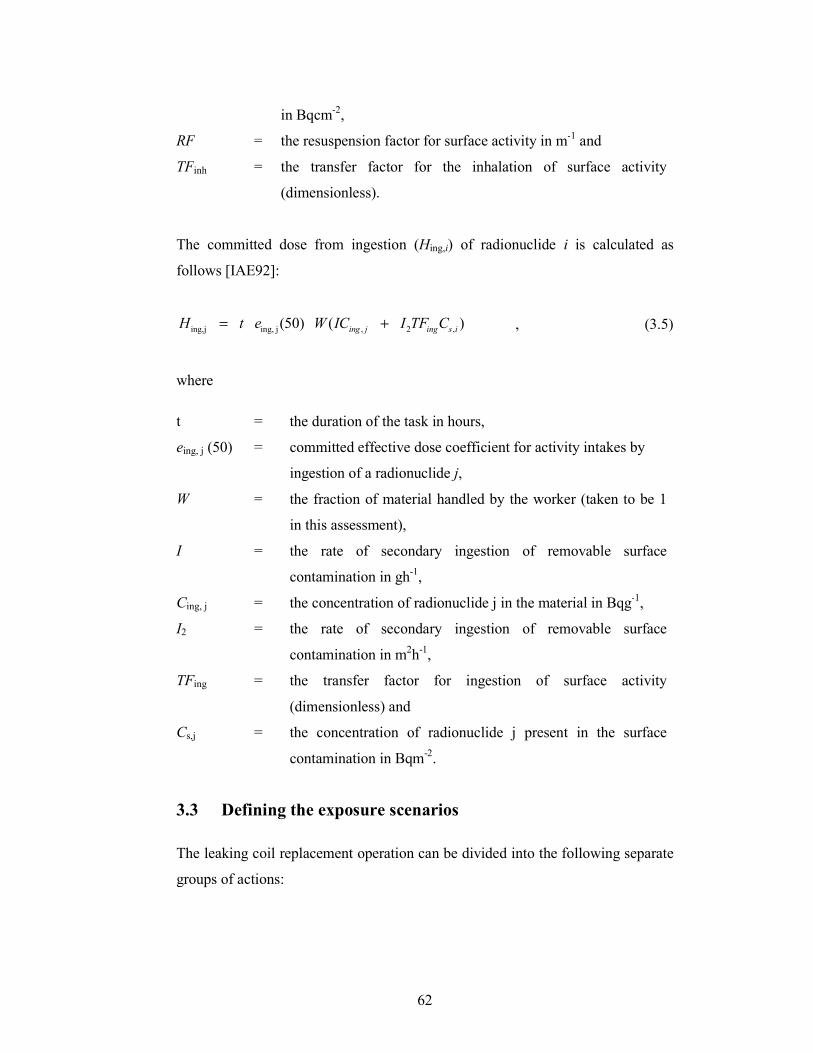
62
in Bqcm-2,
RF = the resuspension factor for surface activity in m-1 and
TFinh = the transfer factor for the inhalation of surface activity
(dimensionless).
The committed dose from ingestion (Hing,i) of radionuclide i is calculated as
follows [IAE92]:
ing,j ing, j , 2 ,(50) ( )
ing j ing s iH t e W IC I TF C= + , (3.5)
where
t = the duration of the task in hours,
eing, j (50) = committed effective dose coefficient for activity intakes by
ingestion of a radionuclide j,
W = the fraction of material handled by the worker (taken to be 1
in this assessment),
I = the rate of secondary ingestion of removable surface
contamination in gh-1,
Cing, j = the concentration of radionuclide j in the material in Bqg-1,
I2 = the rate of secondary ingestion of removable surface
contamination in m2h-1,
TFing = the transfer factor for ingestion of surface activity
(dimensionless) and
Cs,j = the concentration of radionuclide j present in the surface
contamination in Bqm-2
.
3.3 Defining the exposure scenarios
The leaking coil replacement operation can be divided into the following separate
groups of actions:

63
• preparatory work to be performed in the area to support the
evaporator structure for the removal of a section from it,
• removal of lagging from evaporator,
• initial loosening of bolts,
• cutting by plasma torch of the defunct evaporator,
• collection and removal of all parts and waste generated from the
area,
• placement of the sections of the new evaporator unit into place and
• completion of new installation including new lagging, torque of
bolts, and removal of tools.
Proper planning of the replacement task by the operators has produced a task list
detailing the following information for each of the above actions:
• detailed description of each task to be performed,
• location of the workers and number of workers relative to the
equipment,
• estimated duration of each task and
• identification of the workers (in case a worker is expected to
perform multiple tasks).
This information is critical to the dose assessment as it defines the actions of the
individual worker involved.
The identified actions were then grouped into scenarios with similar exposure
characteristics:
Scenario 1
Workers are exposed in a scenario where radiation levels are elevated and where
surface contamination is present. Actions associated with all preparatory work
before the containment of the evaporator is compromised (cut). Exposure
pathways encompass external irradiation from the evaporator contents, the
inhalation of contaminated dust and the inadvertent ingestion of contaminated
material (e.g. by the hand to mouth transfer pathway).
64
Scenario 2
Workers perform cutting and removal operations which cause aggressive
resuspension of volume contaminated material in area with elevated radiation
levels. Exposure pathways encompass external radiation from the evaporator
contents, the inhalation of contaminated dust and the inadvertent ingestion of
contaminated material (e.g. by the hand to mouth transfer pathway).
Scenario 3
Workers place new components in place and complete the installation. The
exposure pathways include external radiation from the surrounding evaporator
contents, the inhalation of contaminated dust and the inadvertent ingestion of
contaminated material (e.g. by the hand to mouth transfer pathway) with
significantly lower levels of contamination present.
The scenario are summarised in Table 3.1.
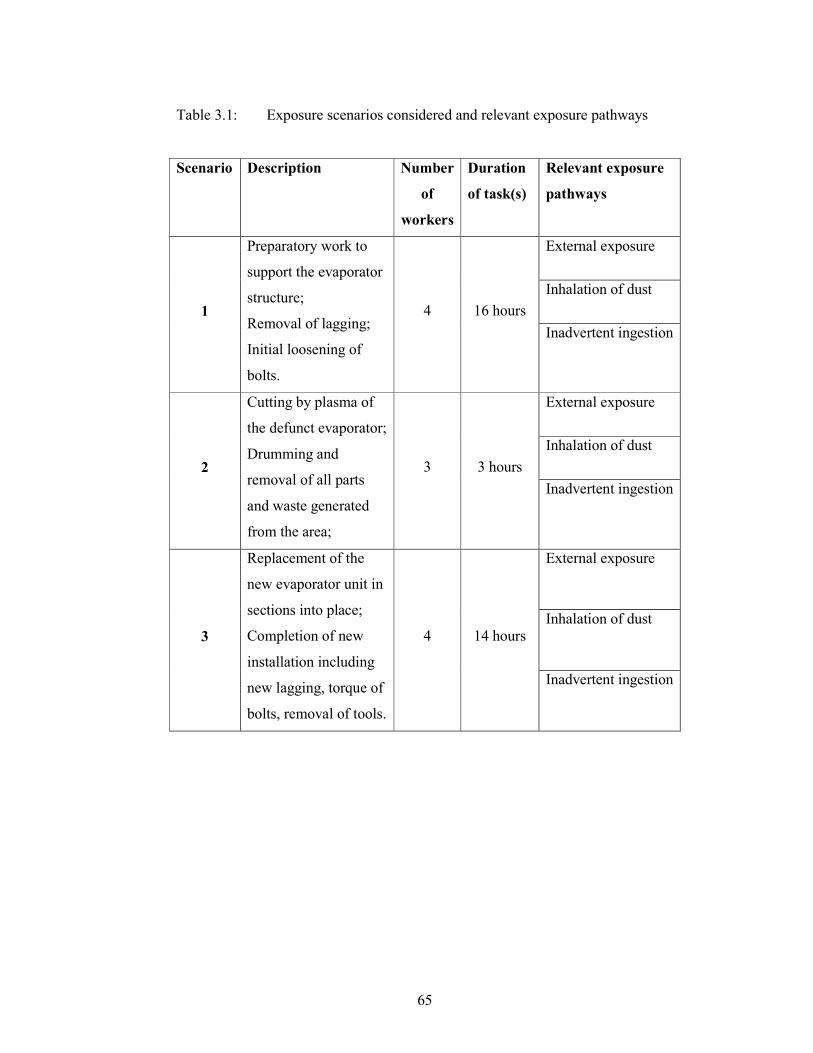
65
Table 3.1: Exposure scenarios considered and relevant exposure pathways
Scenario Description Number
of
workers
Duration
of task(s)
Relevant exposure
pathways
1
Preparatory work to
support the evaporator
structure;
Removal of lagging;
Initial loosening of
bolts.
4 16 hours
External exposure
Inhalation of dust
Inadvertent ingestion
2
Cutting by plasma of
the defunct evaporator;
Drumming and
removal of all parts
and waste generated
from the area;
3 3 hours
External exposure
Inhalation of dust
Inadvertent ingestion
3
Replacement of the
new evaporator unit in
sections into place;
Completion of new
installation including
new lagging, torque of
bolts, removal of tools.
4 14 hours
External exposure
Inhalation of dust
Inadvertent ingestion

66
3.4 Radiological surveillance instrumentation
The radiological surveillance instruments used for the surveillance were
determined based on the radiation properties of the nuclides known to be present
in the facility, using information obtained from the generators of the effluent (see
Section 2.2.4). The nuclides are mainly fission and activation products, which are
known beta and gamma irradiators.
The instruments used in the surveillance are limited to instrument available at the
time of the surveillance and are listed in Table 3.2. Fortunately, all of the
handheld instruments were equipped with digital display meters. Many
instruments still in use today make use of analogue meters which introduces
geotropism [ROL06] and the problem of unstable needle response. All
instruments were calibrated to international standards [IEC02][IEC09][ISO99].
Table 3.2 : List of radiological measuring instrumentation
Measurement type Physical properties Instrument(s)
Contamination levels
Total Surface contamination Thermo Scientific
Electra connected to
DP2R/4A probe
Removable surface
contamination
Gas proportional counter
Radiation levels External radiation Thermo Electron
Corporation Interceptor
Sediment analysis Nuclide identification High purity germanium
(HPGe) detector Activity concentration
Measurement of contamination levels
The instrument selected for the measurement of the total surface contamination
present on the external surfaces of the work area, was the Thermo Scientific
Electra, which is a digital, microprocessor based ratemeter. The ratemeter was
connected to the Thermo Scientific DP2R/4A “dual phosphor probe” which
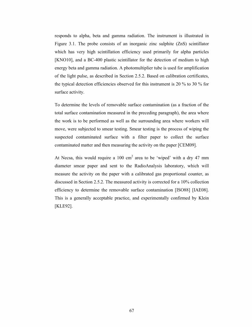
67
responds to alpha, beta and gamma radiation. The instrument is illustrated in
Figure 3.1. The probe consists of an inorganic zinc sulphite (ZnS) scintillator
which has very high scintillation efficiency used primarily for alpha particles
[KNO10], and a BC-400 plastic scintillator for the detection of medium to high
energy beta and gamma radiation. A photomultiplier tube is used for amplification
of the light pulse, as described in Section 2.5.2. Based on calibration certificates,
the typical detection efficiencies observed for this instrument is 20 % to 30 % for
surface activity.
To determine the levels of removable surface contamination (as a fraction of the
total surface contamination measured in the preceding paragraph), the area where
the work is to be performed as well as the surrounding area where workers will
move, were subjected to smear testing. Smear testing is the process of wiping the
suspected contaminated surface with a filter paper to collect the surface
contaminated matter and then measuring the activity on the paper [CEM09].
At Necsa, this would require a 100 cm2 area to be ‘wiped’ with a dry 47 mm
diameter smear paper and sent to the RadioAnalysis laboratory, which will
measure the activity on the paper with a calibrated gas proportional counter, as
discussed in Section 2.5.2. The measured activity is corrected for a 10% collection
efficiency to determine the removable surface contamination [ISO88] [IAE08].
This is a generally acceptable practice, and experimentally confirmed by Klein
[KLE92].

68
Figure 3.1 : Portable contamination monitor
Measurement of radiation levels and nuclide identification
The instrument used for the measurement of radiation levels was the Thermo
Electron Corporation Interceptor, depicted in Figure 3.2. This is a portable
radiation detector suitable for the measurement of gamma dose rate with isotope
identification capability through three Cadmium-Zinc-Telluride (CZT) detectors.
Only one of the CZT detectors is used for isotope identification with a quoted
gamma-ray energy range of 30 keV – 1.5 MeV with an energy resolution of 2.4%
- 3.5% FWHM for the 662 keV gamma ray for 137Cs, when measuring a gamma-
ray energy spectrum on 1024 channels [INT08]. CZT detectors consist of room
temperature semiconductors that directly convert X-ray or gamma-ray photons
into electrons for detection. It is a new technology which sacrifices resolution for
size [FRA05].
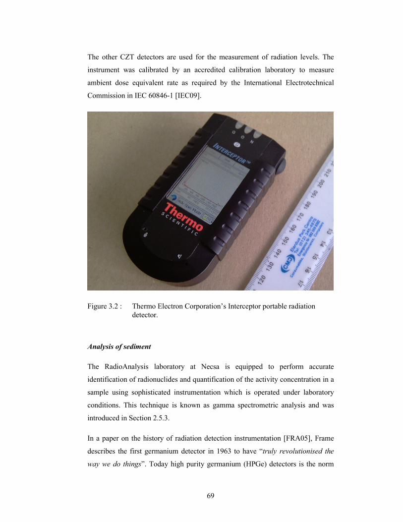
69
The other CZT detectors are used for the measurement of radiation levels. The
instrument was calibrated by an accredited calibration laboratory to measure
ambient dose equivalent rate as required by the International Electrotechnical
Commission in IEC 60846-1 [IEC09].
Figure 3.2 : Thermo Electron Corporation’s Interceptor portable radiation
detector.
Analysis of sediment
The RadioAnalysis laboratory at Necsa is equipped to perform accurate
identification of radionuclides and quantification of the activity concentration in a
sample using sophisticated instrumentation which is operated under laboratory
conditions. This technique is known as gamma spectrometric analysis and was
introduced in Section 2.5.3.
In a paper on the history of radiation detection instrumentation [FRA05], Frame
describes the first germanium detector in 1963 to have “truly revolutionised the
way we do things”. Today high purity germanium (HPGe) detectors is the norm
70
for laboratory analysis because of many advantages, including the ability to warm
to room temperature compared to older germanium systems which had to be
continuously maintained at low temperatures [KNO10].
The RadioAnalysis laboratory performs analysis using a calibrated coaxial high
purity germanium (HPGe) detection system.
3.5 External dose calculation
The external doses will be calculated using the results from a radiological
surveillance and a defined set of exposure scenarios for which a set of formulae
and assumptions are needed. The exposure scenario for external exposure is
described in Table 3.1 based on the tasks and workers defined in Section 3.3.
3.5.1 Interpretation of measurement data
A radiological surveillance was performed in the area where the task will be
performed. It is important to note that the area was subjected to cleaning with a
high pressure water spray apparatus to remove as far as practically possible loose
contamination. Since the potential for effluent leakage from the facility exist, the
room was designed to accumulate any such effluent in a bunded area. The effluent
from this wash-down facility was thus collected in the bunded area and rerouted
as medium activity effluent back into the process. This is considered an ALARA
measure since the potential for exposure was reduced.
Measurements were performed by a radiation protection officer using the Thermo
Electron Corporation Interceptor to determine the external dose rates as well as
some spectrometric measurements (discussed in Section 2.5.3). Ambient dose
equivalent rate measurements were performed at four radial positions at three
intervals along the vertical axis of the evaporator at a distance of 500 mm from the
outer surface of the evaporator shell, as detailed in Figure 3.3. The distance of 500
mm from the outer surface was considered representative of the location that a
worker’s body would be.
71
3.5.2 Identification of relevant nuclides
Spectrometric measurements were performed using the Thermo Electron
Corporation Interceptor discussed in Section 3.4. It is important to note that the
instrument is not capable of quantifying the result of such measurement as such
measurements are highly dependent on the configuration of use (source detector
distance, physical size of source, etc.).
Table 3.3 summarises the results of measurements taken with the Thermo
Electron Corporation Interceptor placed within four angular points on evaporator
at three different positions.
Spectrometric measurements were performed using the Thermo Electron
Corporation Interceptor discussed in Section 3.4. It is important to note that the
instrument is not capable of quantifying the result of such measurement as such
measurements are highly dependent on the configuration of use (source detector
distance, physical size of source, etc.).
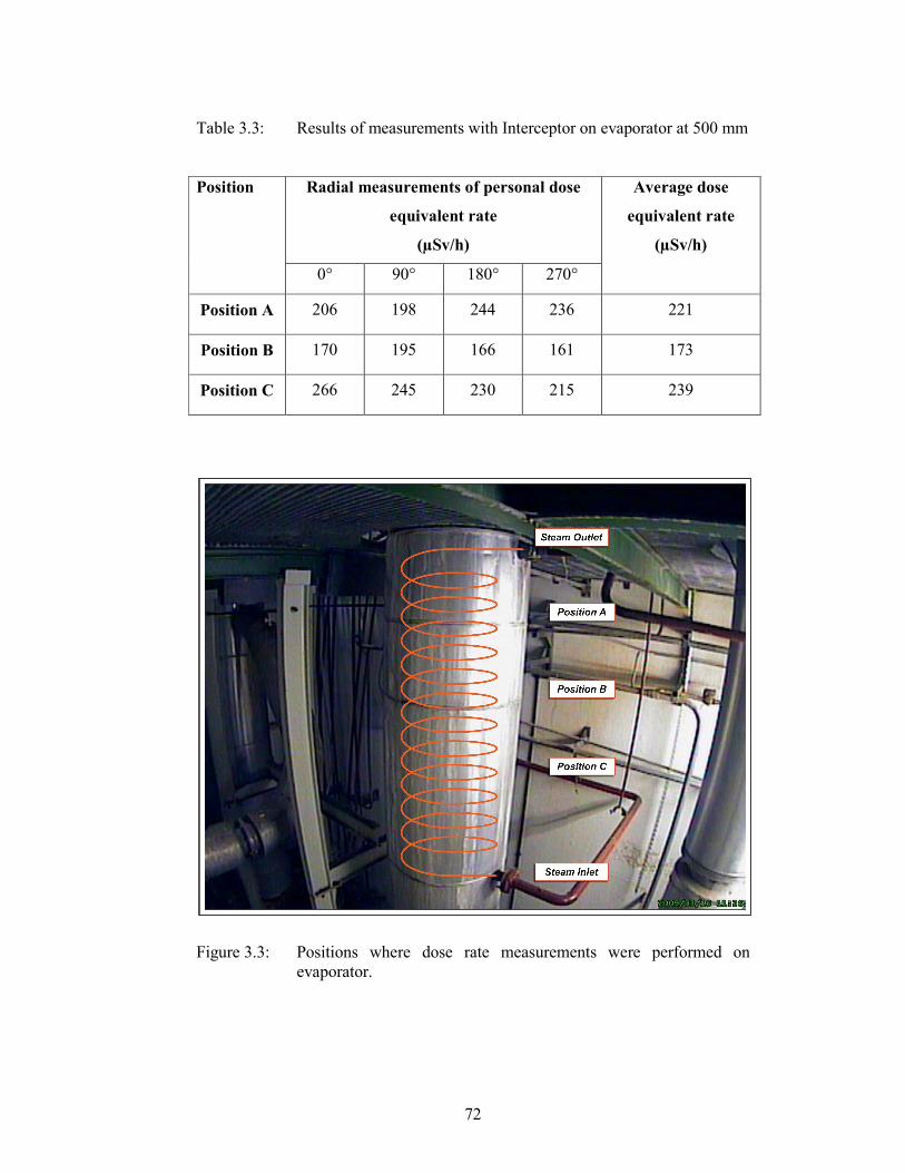
72
Table 3.3: Results of measurements with Interceptor on evaporator at 500 mm
Position Radial measurements of personal dose
equivalent rate
(µSv/h)
Average dose
equivalent rate
(µSv/h)
0° 90° 180° 270°
Position A 206 198 244 236 221
Position B 170 195 166 161 173
Position C 266 245 230 215 239
Figure 3.3: Positions where dose rate measurements were performed on
evaporator.
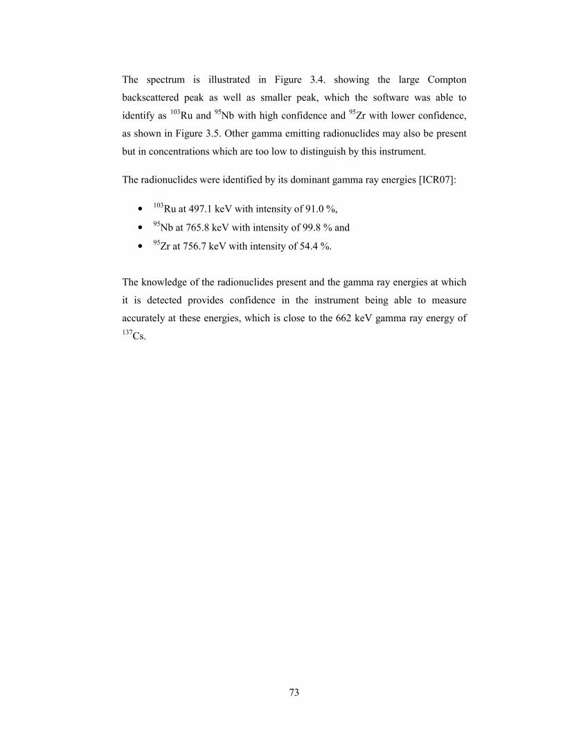
73
The spectrum is illustrated in Figure 3.4. showing the large Compton
backscattered peak as well as smaller peak, which the software was able to
identify as 103Ru and 95Nb with high confidence and 95Zr with lower confidence,
as shown in Figure 3.5. Other gamma emitting radionuclides may also be present
but in concentrations which are too low to distinguish by this instrument.
The radionuclides were identified by its dominant gamma ray energies [ICR07]:
• 103Ru at 497.1 keV with intensity of 91.0 %,
• 95
Nb at 765.8 keV with intensity of 99.8 % and
• 95Zr at 756.7 keV with intensity of 54.4 %.
The knowledge of the radionuclides present and the gamma ray energies at which
it is detected provides confidence in the instrument being able to measure
accurately at these energies, which is close to the 662 keV gamma ray energy of
137Cs.
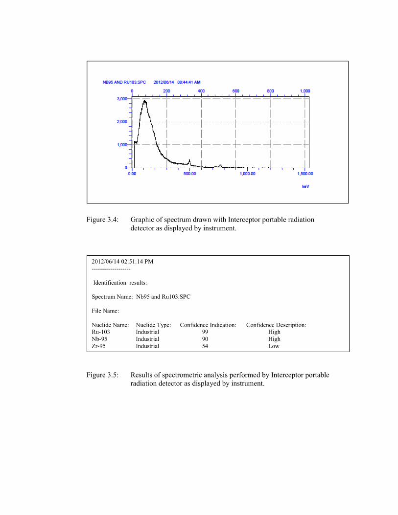
Figure 3.4: Graphic of spectrum drawn with Interceptor portable radiation
detector as displayed by instrument.
Figure 3.5: Results of spectrometric analysis performed by Interceptor portable
radiation detector as displayed by instrument.
2012/06/14 02:51:14 PM
-------------------
Identification results:
Spectrum Name: Nb95 and Ru103.SPC
File Name:
Nuclide Name: Nuclide Type: Confidence Indication: Confidence Description:
Ru-103 Industrial 99 High
Nb-95 Industrial 90 High
Zr-95 Industrial 54 Low
75
3.5.3 Assumption used for external dose calculation
For the calculation of the external dose to the workers, some assumptions
regarding the exposure scenarios and the measurement results apply. These are
discussed further.
Correction for decay of radionuclides
The radionuclides identified in Section 3.5.2 have half-lifes of 39.26 days for
103Ru, 34.991 days for 95Nb and 64.032 days for 95Zr [ICR07].
No correction for radioactive decay will be applied as it was assumed that the
work will be performed within a short space of time (typically one week) and that
the radionuclides contributing to the measured external dose rate, reported in the
preceding section, will remain present in the evaporator as a result of the ongoing
operation of the evaporator.
Exposure times
The exposure times provided in Table 3.1 are based on the time periods planned
by the project team based on a detailed work analysis.
It is furthermore assumed that all the workers will be exposed for the duration of
the periods given. This is a conservative assumption as not all of the workers will
be exposed all of the time; a certain task might require only one worker at a time
to be exposed.
Ambient dose equivalent rates
The measured dose rates are considered representative of the exposure scenarios
presented for Scenarios 1 and 2. For Scenario 3 the dose rates after removal of the
defunct evaporator unit is not known prospectively. It is conservatively assumed
that the dose rate will not change. After completion of the removal tasks, it is
recommended that the dose rate be measured and the results either confirmed or
re-evaluated.
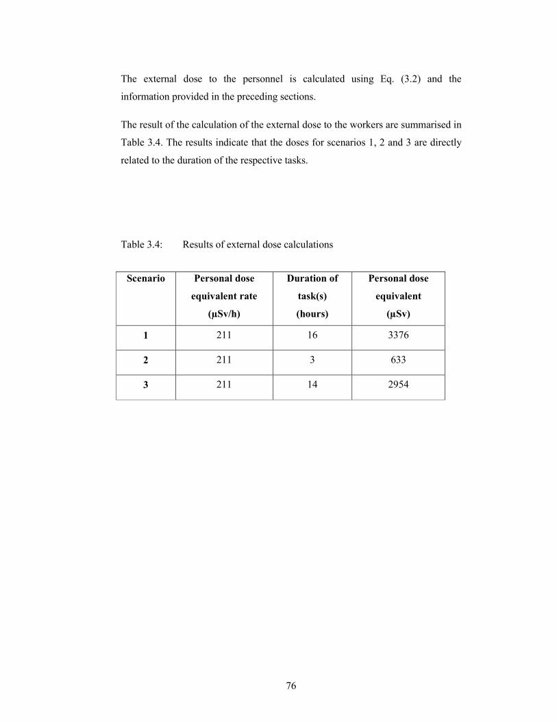
76
The external dose to the personnel is calculated using Eq. (3.2) and the
information provided in the preceding sections.
The result of the calculation of the external dose to the workers are summarised in
Table 3.4. The results indicate that the doses for scenarios 1, 2 and 3 are directly
related to the duration of the respective tasks.
Table 3.4: Results of external dose calculations
Scenario Personal dose
equivalent rate
(µSv/h)
Duration of
task(s)
(hours)
Personal dose
equivalent
(µSv)
1 211 16 3376
2 211 3 633
3 211 14 2954
77
3.6 Internal dose calculation
The internal doses were calculated using the results from a radiological
surveillance, a defined set of exposure scenarios, a set of formulae and
assumptions (where needed) as discussed in the preceding sections.
Following the washdown of the facility, loose contamination has been confirmed
to remain present on surfaces such as walls, railings, grids and the evaporator
outer surface. The risk from internal exposure, however, will be significantly
increased once the integrity of the confinement of the evaporator is breached, that
is when the evaporator is cut to remove the damaged sections.
3.6.1 Interpretation of measured data
The contamination levels were determined by smear samples and sediment
analysis, and are used in the calculations of the internal exposure to workers.
Total surface contamination levels
The intention of the surveillance was to use the Thermo Scientific Electra with
DP2R/4A scintillation detector, described in Section 3.4, to measure the total
surface contamination levels.
As stated in Section 3.4, the instrument responds to “medium to high energy beta
and gamma radiation”. The high prevalent radiation levels reported in Table 3.3
will result in the instrument showing high readings in the beta contamination
mode which the instrument is not able to distinguish from gamma rays. Therefore,
the instrument is not suitable to quantify the total beta surface contamination
levels. In the alpha mode, the instrument readings are not affected by the high
radiation levels. Measurements in the alpha mode indicated that alpha surface
contamination is very low in the room or on the equipment.
Removable surface contamination results
The analysis result of smear samples, described in Section 3.4, taken on the
external surfaces of the evaporator were alpha contamination of 200 Bqm-2 and
beta contamination of 461 000 Bqm-2.
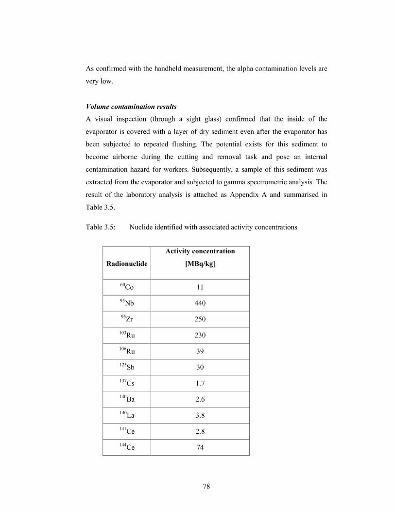
78
As confirmed with the handheld measurement, the alpha contamination levels are
very low.
Volume contamination results
A visual inspection (through a sight glass) confirmed that the inside of the
evaporator is covered with a layer of dry sediment even after the evaporator has
been subjected to repeated flushing. The potential exists for this sediment to
become airborne during the cutting and removal task and pose an internal
contamination hazard for workers. Subsequently, a sample of this sediment was
extracted from the evaporator and subjected to gamma spectrometric analysis. The
result of the laboratory analysis is attached as Appendix A and summarised in
Table 3.5.
Table 3.5: Nuclide identified with associated activity concentrations
Radionuclide
Activity concentration
[MBq/kg]
60Co 11
95Nb 440
95Zr 250
103Ru 230
106Ru 39
125Sb 30
137Cs 1.7
140Ba 2.6
140La 3.8
141Ce 2.8
144Ce 74
79
The RadioAnalysis laboratory performed analysis using a calibrated coaxial high
purity germanium (HPGe) detection system, described in Section 3.4. Results in
Table 3.5 indicate high activity concentration of 95Nb, 95Zr and 103Ru, with other
radionuclides in lower concentrations. This confirms the results of the handheld
instrument in Section3.5.2.
The presence of these radionuclides was expected. Although fission product yields
are well known, their relative contribution to a mixture that contains corrosion
activation products is not easy to predict, according to Thind [THI01]. In his
paper, Thind suggest that 95Zr and 95Nb are created from two sources, namely fuel
and fuel cladding, and therefore might constitute a significant fraction of the total
activity in the mixture, as observed in the analysis result in Appendix A.
The radiological hazards of 95Zr and 95Nb are also well known and studied, as
confirmed in a paper by Fletcher [FLE68] on studies performed on rats and dating
back to 1968, in which references to papers dating back to 1947 are made.
3.6.2 Assumptions used for internal dose calculations
For the calculation of the internal doses to the workers, some assumptions
regarding the exposure scenarios and the measurement results apply. These are
discussed further.
Correction for decay of radionuclides
As stated in Section, 3.5.3, no correction for radioactive decay will be applied.
Exposure times
The exposure times provided in Table 3.1 are based on the time periods planned
by the project team based on a detailed work analysis.
It is furthermore assumed that all the workers will be exposed for the duration of
the periods given. This is a conservative assumption as not all of the workers will
be exposed all of the time; certain task might require only one worker at a time to
be exposed.
80
Activity concentration of volume contaminated material
The activity concentration as determined from analysis of the sediment inside the
evaporator will be used in all calculations, assuming a uniform distribution inside
the evaporator as a result of the operations inside the evaporator.
Activity concentration of surface contaminated material
The results of the measured removable surface contaminated levels will be used
for the calculations. The alpha contamination levels are very low and will be
excluded as its contribution is considered to be less than 0.1% of the total activity.
The radionuclide present in the beta surface contamination are assumed to be
similar relative radionuclide contribution to that of the scale analysed since no
other radionuclides is expected in the room and contamination is spread as a result
of breaches in the containment of the evaporator during typical maintenance tasks.
Therefore, the surface contamination will be scaled according to the relative
radionuclide contribution, as shown in Table 3.6.
Studies on surface phenomena associated with the particle size distribution of the
materials has shown that many factors can influence the actual inhaled or ingested
activity, such as the type of material, its physical and chemical properties, and the
origin and possible later redistribution of the contamination. For this assessment,
the generic approach is deemed appropriate and no additional factoring for these
phenomena will be applied.
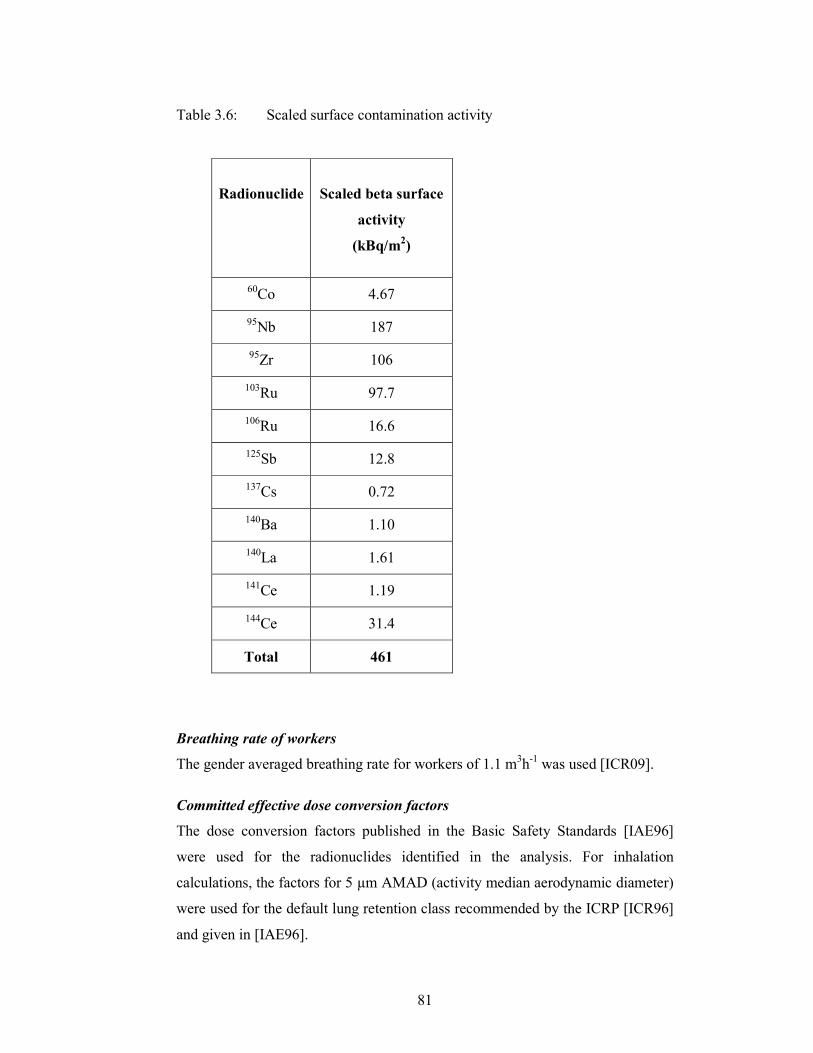
81
Table 3.6: Scaled surface contamination activity
Radionuclide
Scaled beta surface
activity
(kBq/m2)
60Co 4.67
95Nb 187
95Zr 106
103Ru 97.7
106Ru 16.6
125Sb 12.8
137Cs 0.72
140Ba 1.10
140La 1.61
141Ce 1.19
144Ce 31.4
Total 461
Breathing rate of workers
The gender averaged breathing rate for workers of 1.1 m3h
-1 was used [ICR09].
Committed effective dose conversion factors
The dose conversion factors published in the Basic Safety Standards [IAE96]
were used for the radionuclides identified in the analysis. For inhalation
calculations, the factors for 5 µm AMAD (activity median aerodynamic diameter)
were used for the default lung retention class recommended by the ICRP [ICR96]
and given in [IAE96].
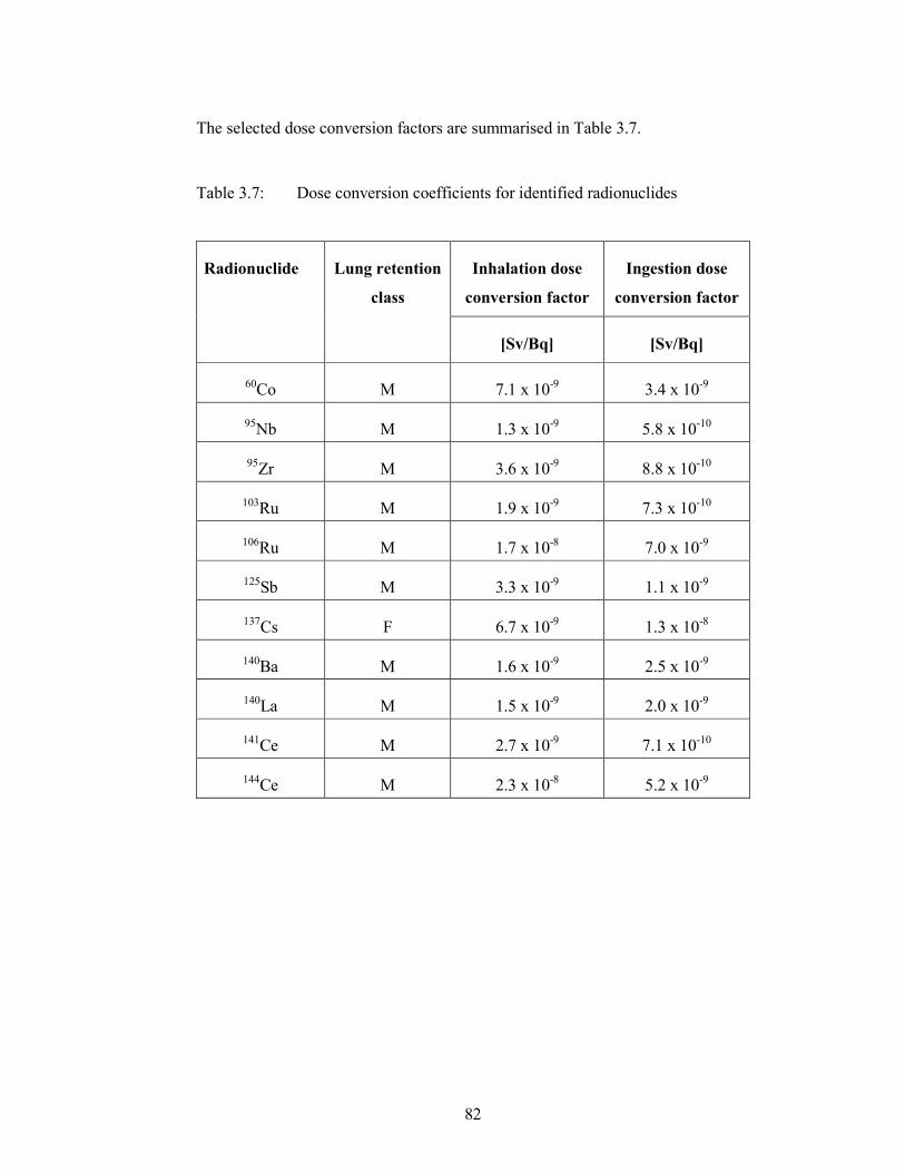
82
The selected dose conversion factors are summarised in Table 3.7.
Table 3.7: Dose conversion coefficients for identified radionuclides
Radionuclide Lung retention
class
Inhalation dose
conversion factor
Ingestion dose
conversion factor
[Sv/Bq] [Sv/Bq]
60Co M 7.1 x 10⁻⁹ 3.4 x 10⁻⁹
95Nb M 1.3 x 10
-9 5.8 x 10
-10
95Zr M 3.6 x 10
-9 8.8 x 10
-10
103Ru M 1.9 x 10⁻⁹ 7.3 x 10⁻¹⁰
106Ru M 1.7 x 10⁻⁸ 7.0 x 10⁻⁹
125Sb M 3.3 x 10⁻⁹ 1.1 x 10⁻⁹
137Cs F 6.7 x 10
-9 1.3 x 10
-8
140Ba M 1.6 x 10⁻⁹ 2.5 x 10⁻⁹
140La M 1.5 x 10⁻⁹ 2.0 x 10⁻⁹
141Ce M 2.7 x 10⁻⁹ 7.1 x 10⁻¹⁰
144Ce M 2.3 x 10⁻⁸ 5.2 x 10⁻⁹

83
Concentration of respirable dust in air
This concentration of respirable dust in air (also known as dust load) is dependent
upon the type of work to be performed. A value of 1 x 10⁻³ gm-3 is recommended
by the IAEA [IAE92] for building renovation actions.
Resuspension factor for surface activity
The phenomena of resuspension from surface activity have been widely studied
and several reports are available from literature.
The resuspension factor is defined as the quantitative relationship between the
concentration of loose surface contamination and consequent atmospheric
concentration above the contaminated surface [CEM09]. This handbook also
notes the variation in the resuspension factor to be between 10-4 and 10-8 m-1 and
recommends 1 x 10⁻⁶ m-1 as a ‘reasonable’ value.
As early as 1953 a report by the United States Atomic Energy Commission
[BAI53] illustrated the variability in the factors, with ranges from 2.5 x 10⁻⁵ to 1.9
x 10-4 m-1 for long continuous operations and a maximum activity of 2.0 x 10⁻³ m-1
subject to fairly extreme operational conditions for short periods. As more studies
were performed in later years and more knowledge gained, later publications
showed significantly reduced factors.
The IAEA has several documents where resuspension is encountered. In one
document dating back to 1992, a value of 1 x 10⁻⁶ m-1 is used for typical
decommissioning scenarios [IAE92].
In a more recent IAEA publication from 2008, the Advisory Material for the
Transport Regulations [IAE08], reference is still made to research reports
spanning back to 1970 and makes a recommendation of 5 x 10⁻⁵ m-1 as the value
“recommended for general use by the IAEA” [IAE08]. This value is subsequently
also used in this work and in the IAEA publication [IAE08] to justify the
derivation of surface contamination limits in the IAEA Transport Regulations
[IAE09a].
84
In the IAEA Tecdoc 1616 [IAE09b], an article by F. Jourdin is published where a
study was performed on resuspension for a range of radionuclides and conditions
which included in-situ experiments. This article concludes with statements on the
very high variability of measured resuspension factors and low accuracies of
model predictions.
Another source is the DOE Handbook [DOE94] where resuspension scenarios for
a variety of materials in different physical forms are reported. This report
recommends a resuspension factor of 4 x 10⁻⁵ m-1 for solids in powder form.
In 2001 Necsa reported to the NNR on data collected during local
decommissioning activities over a period of time [AA5524]. The average
calculated resuspension factor was 1.7 x 10⁻⁶ m-1 which was rounded to 2.0 x 10⁻⁶
m-1. This value was accepted by the NNR and is currently still in use for safety
assessment purposes.
Given the variability of the resuspension factors and the Necsa specific scenarios
encountered, for this study a resuspension factor of 2.0 x 10⁻⁶ m-1 is used.
Transfer factor for the inhalation of surface activity
This is the fraction of surface contamination available for resuspension and is a
dimensionless value. Although the IAEA recommends 1 x 10⁻⁶ in [IAE92], Necsa
has agreed with the NNR to use a value of 1 [AA5524]. At the time it was
reasoned that the calculations considered removable surface contamination
present on the surface of which 100% is available for resuspension.
For this study, a transfer factor of 1 will be used.
Rate of secondary ingestion of removable surface contamination
The IAEA makes the assumption that adult workers will ingest 10 mg of
contamination per hour [IAE92].
It furthermore recommends the use of a secondary ingestion rate of 1 x 10⁻⁴ m2h-1
for the ingestion of removable surface contamination [IAE92] based on a study
performed by Healy in 1971 [HEA71].
85
Transfer factor for ingestion of surface activity
This dimensionless factor is given as 1 x 10⁻² by the IAEA in [IAE92].
The internal doses to the workers were calculated using Eqs. (3.4) and (3.5) and
the information provided in the preceding sections.
3.6.3 Results
Results of the calculation of the internal dose to workers are summarised in Table
3.8. The results are presented graphically in Figure 3.6 and Figure 3.7. From the
graphic in Figure 3.6 the following observations are made:
• the total internal dose contributions from the radionuclides with the
highest activity concentration, namely 95Nb (16.7%), 95Zr (16.8%) and
103Ru (18.2%), is responsible for almost half of the internal exposure,
• the relative contribution from 144
Ce, at 30.1%, is the largest single
radionuclides contribution which is as a result of both the inhalation and
ingestion dose conversion factors for 144Ce being the highest of the
nuclides analysed and
• 106Ru has a significant contribution of 18%.
From Figure 3.7, the following observations can be made:
• the inhalation dose is higher than the ingestion dose by a factor of 6.99 for
the workers in scenarios 1 and 3 and
• the ingestion dose is higher than inhalation dose by a factor of 2.86 for
workers in scenario 2.
The latter is due to the assumption that workers in scenario 1 will be exposed to
airborne sediment during aggressive cutting actions.
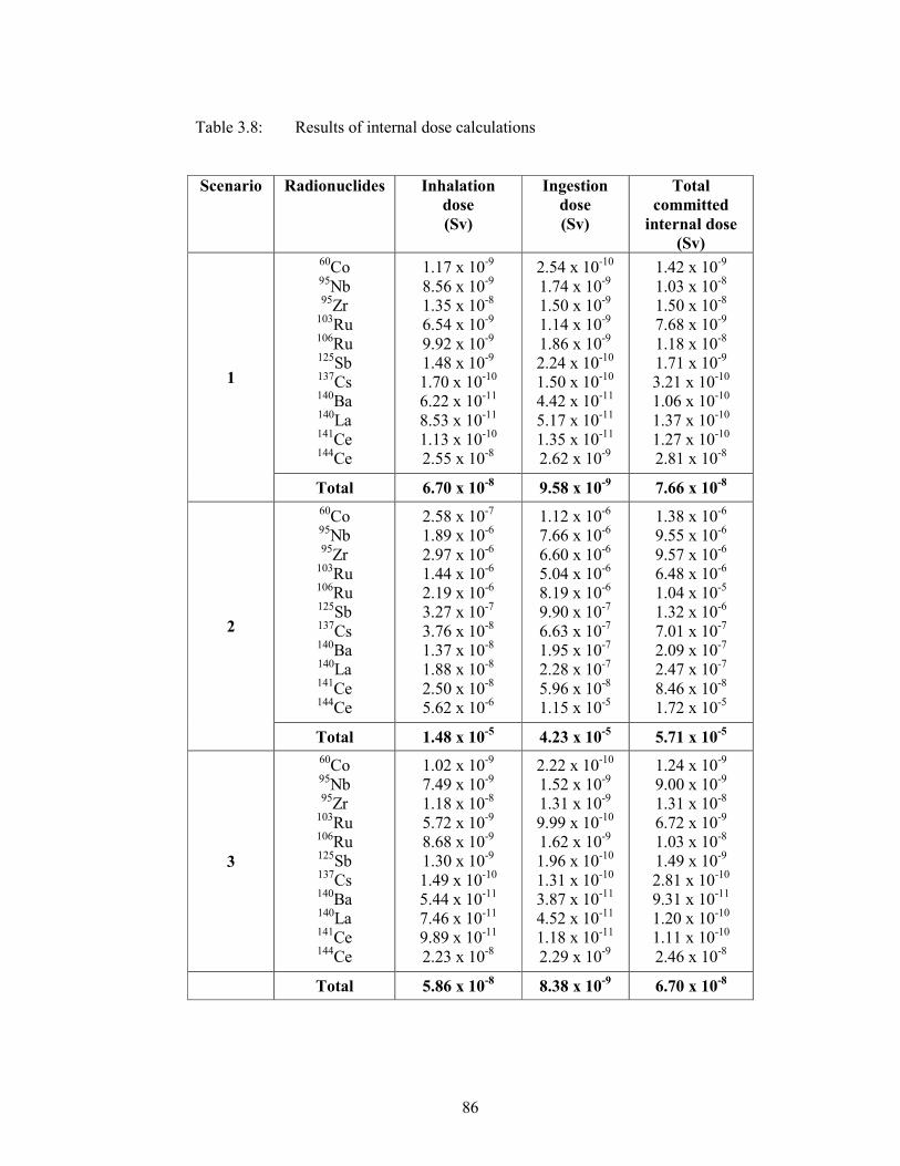
86
Table 3.8: Results of internal dose calculations
Scenario Radionuclides Inhalation
dose
(Sv)
Ingestion
dose
(Sv)
Total
committed
internal dose
(Sv)
1
60Co 95
Nb 95Zr
103Ru 106
Ru 125Sb 137Cs 140Ba 140
La 141Ce 144Ce
1.17 x 10⁻⁹
8.56 x 10⁻⁹
1.35 x 10⁻⁸
6.54 x 10⁻⁹
9.92 x 10⁻⁹
1.48 x 10⁻⁹
1.70 x 10⁻¹⁰
6.22 x 10⁻¹¹
8.53 x 10⁻¹¹
1.13 x 10⁻¹⁰
2.55 x 10⁻⁸
2.54 x 10⁻¹⁰
1.74 x 10⁻⁹
1.50 x 10⁻⁹
1.14 x 10⁻⁹
1.86 x 10⁻⁹
2.24 x 10⁻¹⁰
1.50 x 10⁻¹⁰
4.42 x 10⁻¹¹
5.17 x 10⁻¹¹
1.35 x 10⁻¹¹
2.62 x 10⁻⁹
1.42 x 10⁻⁹
1.03 x 10⁻⁸
1.50 x 10⁻⁸
7.68 x 10⁻⁹
1.18 x 10⁻⁸
1.71 x 10⁻⁹
3.21 x 10⁻¹⁰
1.06 x 10⁻¹⁰
1.37 x 10⁻¹⁰
1.27 x 10⁻¹⁰
2.81 x 10⁻⁸
Total
6.70 x 10⁻⁸
9.58 x 10⁻⁹
7.66 x 10⁻⁸
2
60Co 95Nb 95
Zr 103Ru 106Ru 125Sb 137
Cs 140Ba 140La 141
Ce 144Ce
2.58 x 10⁻⁷
1.89 x 10⁻⁶
2.97 x 10⁻⁶
1.44 x 10⁻⁶
2.19 x 10⁻⁶
3.27 x 10⁻⁷
3.76 x 10⁻⁸
1.37 x 10⁻⁸
1.88 x 10⁻⁸
2.50 x 10⁻⁸
5.62 x 10⁻⁶
1.12 x 10⁻⁶
7.66 x 10⁻⁶
6.60 x 10⁻⁶
5.04 x 10⁻⁶
8.19 x 10⁻⁶
9.90 x 10⁻⁷
6.63 x 10⁻⁷
1.95 x 10⁻⁷
2.28 x 10⁻⁷
5.96 x 10⁻⁸
1.15 x 10⁻⁵
1.38 x 10⁻⁶
9.55 x 10⁻⁶
9.57 x 10⁻⁶
6.48 x 10⁻⁶
1.04 x 10⁻⁵
1.32 x 10⁻⁶
7.01 x 10⁻⁷
2.09 x 10⁻⁷
2.47 x 10⁻⁷
8.46 x 10⁻⁸
1.72 x 10⁻⁵
Total
1.48 x 10⁻⁵
4.23 x 10⁻⁵
5.71 x 10⁻⁵
3
60Co
95Nb 95Zr
103Ru
106Ru 125Sb 137
Cs 140
Ba 140La 141Ce 144
Ce
1.02 x 10⁻⁹
7.49 x 10⁻⁹
1.18 x 10⁻⁸
5.72 x 10⁻⁹
8.68 x 10⁻⁹
1.30 x 10⁻⁹
1.49 x 10⁻¹⁰
5.44 x 10⁻¹¹
7.46 x 10⁻¹¹
9.89 x 10⁻¹¹
2.23 x 10⁻⁸
2.22 x 10⁻¹⁰
1.52 x 10⁻⁹
1.31 x 10⁻⁹
9.99 x 10⁻¹⁰
1.62 x 10⁻⁹
1.96 x 10⁻¹⁰
1.31 x 10⁻¹⁰
3.87 x 10⁻¹¹
4.52 x 10⁻¹¹
1.18 x 10⁻¹¹
2.29 x 10⁻⁹
1.24 x 10⁻⁹
9.00 x 10⁻⁹
1.31 x 10⁻⁸
6.72 x 10⁻⁹
1.03 x 10⁻⁸
1.49 x 10⁻⁹
2.81 x 10⁻¹⁰
9.31 x 10⁻¹¹
1.20 x 10⁻¹⁰
1.11 x 10⁻¹⁰
2.46 x 10⁻⁸
Total
5.86 x 10⁻⁸
8.38 x 10⁻⁹
6.70 x 10⁻⁸
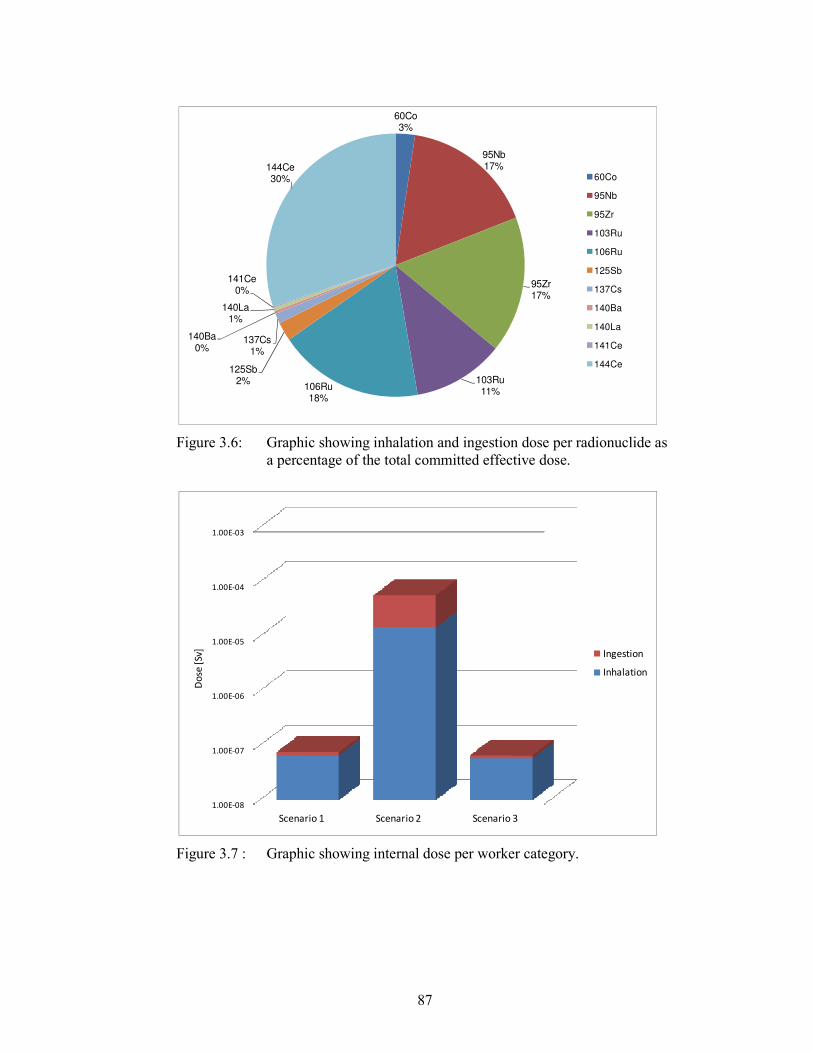
87
Figure 3.6: Graphic showing inhalation and ingestion dose per radionuclide as
a percentage of the total committed effective dose.
Figure 3.7 : Graphic showing internal dose per worker category.
60Co
3%
95Nb
17%
95Zr
17%
103Ru
11%106Ru
18%
125Sb
2%
137Cs
1%
140Ba
0%
140La
1%
141Ce
0%
144Ce
30% 60Co
95Nb
95Zr
103Ru
106Ru
125Sb
137Cs
140Ba
140La
141Ce
144Ce
1.00E-08
1.00E-07
1.00E-06
1.00E-05
1.00E-04
1.00E-03
Scenario 1 Scenario 2 Scenario 3
Do
se [
Sv]
Ingestion
Inhalation
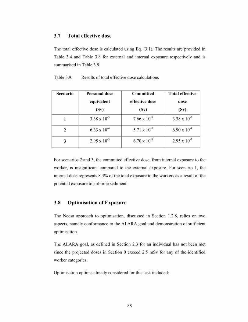
88
3.7 Total effective dose
The total effective dose is calculated using Eq. (3.1). The results are provided in
Table 3.4 and Table 3.8 for external and internal exposure respectively and is
summarised in Table 3.9.
Table 3.9: Results of total effective dose calculations
Scenario Personal dose
equivalent
(Sv)
Committed
effective dose
(Sv)
Total effective
dose
(Sv)
1 3.38 x 10⁻³ 7.66 x 10⁻⁸ 3.38 x 10⁻³
2 6.33 x 10⁻⁴ 5.71 x 10⁻⁵ 6.90 x 10⁻⁴
3 2.95 x 10⁻³ 6.70 x 10⁻⁸ 2.95 x 10⁻³
For scenarios 2 and 3, the committed effective dose, from internal exposure to the
worker, is insignificant compared to the external exposure. For scenario 1, the
internal dose represents 8.3% of the total exposure to the workers as a result of the
potential exposure to airborne sediment.
3.8 Optimisation of Exposure
The Necsa approach to optimisation, discussed in Section 1.2.8, relies on two
aspects, namely conformance to the ALARA goal and demonstration of sufficient
optimisation.
The ALARA goal, as defined in Section 2.3 for an individual has not been met
since the projected doses in Section 0 exceed 2.5 mSv for any of the identified
worker categories.
Optimisation options already considered for this task included:
89
• a need for a formal ALARA planning and review since the estimated
individual dose exceeds 1 mSv,
• the use of a dose constraint in the form of the ALARA objective which is
lower than the dose limit,
• the washdown of the facility prior to work being performed which resulted
in decontamination of work surfaces to reduce the potential for internal
exposure,
• the execution of an a priori dose assessment (this research report) to
enable decision making in terms of exposure levels and protective
measures and
• the use of limited personal protective equipment and clothing.
The latter was not considered in the dose assessment and will result in less
hindrance to the worker and less time to dress/undress. This option is further
discussed in Section 3.8.1.
3.8.1 Further optimisation options to reduce internal exposure
The use of personal protection clothing and equipment will result in reduced doses
to workers in contaminated environments due to increased control over the
inadvertent ingestion and inhalation of contaminated materials. This is not simple
to quantify directly since many variables can influence the level of protection,
such as the work procedures followed and the differences between methodologies
followed by different workers. One measure which can result in significant
reduction in the internal exposure, is the use of respiratory protection. A respirator
can provide a protection factor of 10 for inhalation while an air hood can provide
a protection factor of 1000 for inhalation, as published in the American National
Standards as assigned protection factors [ANS92]. An air hood is typically a half
body suit which supplies external fresh air to the worker thereby eliminating the
inhalation of contaminated air from the work place.
However, by not using protective clothing also minimised the time required to
perform the task in that less time is spent dressing and undressing; less
90
physiological stress is placed on the body, less restriction on movement is
experienced and worker efficiency is improved [BEV10].
Although the dose assessment only considered the physical aspects of the task to
be performed, several operational radiation protection practices will ensure the
doses to the workers will be controlled and even reduced during performance of
the work. Examples of these are:
• covering work area with plastic to further reduce spread of contamination
and contamination of tools,
• waste minimisation practices and
• good housekeeping to reduce movement and expedite cleanup after work
is completed.
The use of personal protective clothing should also be put into perspective. For
the three scenarios in this study, the use of protective clothing would not benefit
the scenarios where the internal exposure is already very low.
3.8.2 Further optimisation options to reduce external exposure
The calculated doses are largely as a result of external exposure, thus significant
measures to reduce exposure time (working faster, task training) and reducing
exposure (positioning relative to high exposure rates) can be considered.
The most effective way to reduce the external exposure to workers is to consider
traditional time, distance, shielding and planning approach. The workspace is
restricted in terms of space, which makes changes in terms of distance from the
source of radiation and the use of shielding not viable. The most plausible solution
is to improve on time through planning of work execution. A proposal was
accepted to reduce the allocated period for workers in Scenario 1 and 3 by 30% to
11.2 hours and 9.8 hours respectively. When the doses are calculated, result in
meeting the ALARA goal, as reflected in Table 3.9. Worker 2 was not affected as
the projected time to perform these tasks is of short duration.
The measures to achieve this reduction in time are based upon improved planning:

91
• extensive training of all workers in the procedures,
• training on mock-ups to practice reduction of the time taken to complete
the tasks and to confirm task duration,
• identification of problem areas and
• the use of electronic dosimetry to perform live tracking of doses which
will enable radiation protection personnel to continuously evaluate the
progress of the tasks against the doses incurred and to proactively initiate
control measures or invigilation.
The latter measure introduces a recent technological advancement, which enables
the remote tracking of exposures via a radiofrequency link between the electronic
personal dosimeter worn by the worker and a computer located in another room.
This is a very useful tool for tracking; however, cognisance should be taken of the
differences experienced between doses recorded with thermoluminescence and
electronic dosimeters, noting that the thermoluminescence dosimeter is still
regarded as the official means of dose recording in South Africa. In a paper by
Vanhavere [VAN01] based on studies performed at the SCK•CEN in Belgium, the
electronic dosimeter recorded lower doses. In a more recent publication by Poston
[POS05], a switch to electronic dosimeters in the near future is however projected.
Table 3.10: Results of total effective dose calculations after implementation of
optimisation considerations
Scenario Personal dose
equivalent
(Sv)
Committed
effective dose
(Sv)
Total effective
dose
(Sv)
1 2.37 x 10⁻³
7.66 x 10⁻⁸
2.37 x 10⁻³
2 6.33 x 10⁻⁴
5.71 x 10⁻⁵
6.90 x 10⁻⁴
3 2.07 x 10⁻³
6.70 x 10⁻⁸
2.07 x 10⁻³
92
3.8.3 Recommendations for radiation protection programme
The last steps in the iterative evaluation in Section 1.3.2 is the completion of the
dose assessment and work permit as well as to finalise the work plan and
procedures where all the outcomes of the assessment culminate in the
recommendations for execution of the task and the radiation protection
programme.
93
CHAPTER 4 – CONCLUSIONS AND RECOMMENDATIONS
CONCLUSIONS AND
RECOMMENDATIONS
“Planning is an unnatural process. It is much more fun to do something. The
nicest thing about not planning is that the failure comes as a complete surprise
rather than preceded by a period of worry and depression” – Sir John Harvey-
Jones
The conclusions and recommendations resulting from this study are presented in
this chapter.
4.1 Conclusions from calculations
The results of the dose assessment presented in Chapter 3 and summarised in
shows the highest total effective dose to 2.37 mSv which is within the national
and international dose limits for workers and meets the Necsa ALARA goal of 4
mSv.
The dose assessment was supported by measurement of actual radiological
conditions in the area where the task will be performed using suitable and
calibrated measuring instruments. The benefit of this was that the assumption
needed to perform the dose assessment was limited to the physical phenomena
associated with the behaviour of materials and available from national and
international studies.
Another aspect which provides confidence in the results is the exposure scenarios
which were defined during a proper planning of all the tasks associated with the
replacement of the evaporator coil.
94
Sources of inaccuracy and uncertainty associated with the calculated doses were
discussed in Chapter 3 and are limited to uncertainty in the measurement data and
assumptions. This should be objectively viewed in light of the large variations in
accuracy expected in personnel monitoring. Poston [POS05] reports accuracy in
the order of -50% to +100% for routine monitoring in general.
It is worth noting that the calculations perform in this research report are based on
international methods and formulae. However, the assumptions used are based on
scenarios which are not always applicable or an accurate reflection of the actual
scenario, although considerable effort was made to obtain realistic values.
Subsequently, the results obtained include conservatism. The post task review will
afford the RP professional the opportunity to compare the outcome of the
personnel monitoring with the projected outcome, taking into consideration the
alignment between the planned work plan and the actual work plan.
4.2 Conclusions on ALARA
In Chapters 1 through Chapter 3, much emphasis has been placed on the
requirements, controls and implementation of ALARA. The Fundamental Safety
Principles on ALARA, which were discussed in Section 1.2.1 provided the basis
for evaluating the outcomes of the task to replace the evaporator coil:
Principle 4: Justification of facilities and activities
The evaporator facility treats medium activity effluent as a service to SAFARI-1
and NTP. The radiological exposures involved in the replacement of the
evaporator coil are justified to ensure the continued operation of these facilities,
which produce inter alia medical isotopes.
Principle 5: Optimisation of protection
Optimisation has been demonstrated in Section 3.8. The exposures to workers
were calculated in an a priori dose assessment. The doses conform to the ALARA
objectives of Necsa and other operation optimisation measures. Other dose
reduction options, such as personal protective clothing and equipment, were
considered.
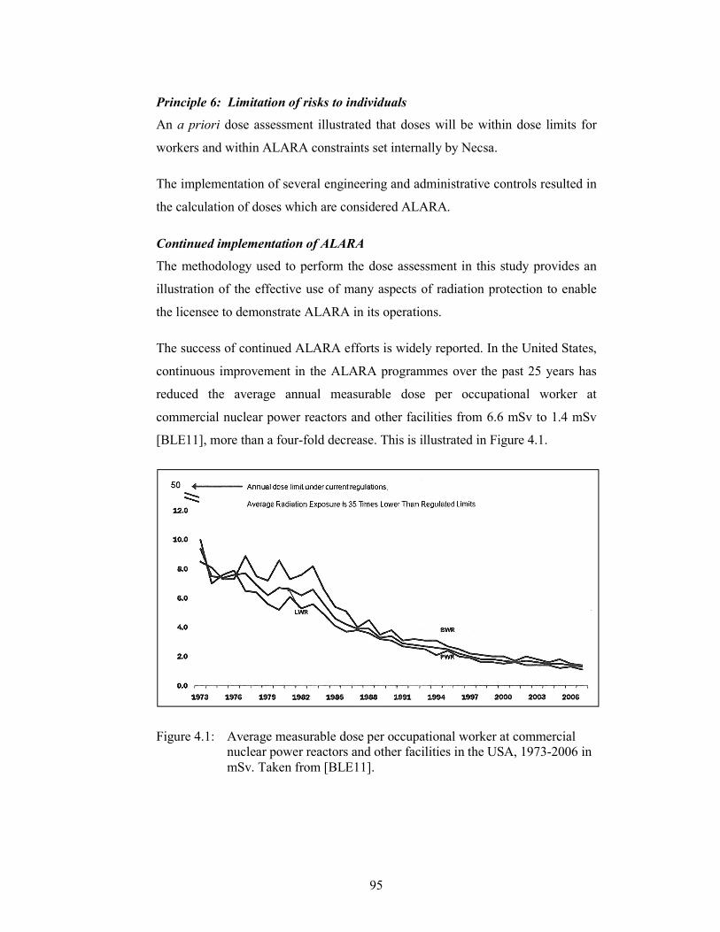
95
Principle 6: Limitation of risks to individuals
An a priori dose assessment illustrated that doses will be within dose limits for
workers and within ALARA constraints set internally by Necsa.
The implementation of several engineering and administrative controls resulted in
the calculation of doses which are considered ALARA.
Continued implementation of ALARA
The methodology used to perform the dose assessment in this study provides an
illustration of the effective use of many aspects of radiation protection to enable
the licensee to demonstrate ALARA in its operations.
The success of continued ALARA efforts is widely reported. In the United States,
continuous improvement in the ALARA programmes over the past 25 years has
reduced the average annual measurable dose per occupational worker at
commercial nuclear power reactors and other facilities from 6.6 mSv to 1.4 mSv
[BLE11], more than a four-fold decrease. This is illustrated in Figure 4.1.
Figure 4.1: Average measurable dose per occupational worker at commercial
nuclear power reactors and other facilities in the USA, 1973-2006 in
mSv. Taken from [BLE11].
96
REFERENCES
[AIT05] S. B. Aitken et al, “High Level Waste Tank Closure Project:
ALARA Applications at the Idaho Engineering and Environmental
Laboratory”, Health Physics Journal, (2005).
[ANS92] American National Standard Institute, “American National
Standard for Respiratory Protection”, ANSI Z88.2-1992 (1992).
[BAI53] J.C. Bailey and R.C. Rohr, “Air-borne contamination resulting
from transferable contamination on surfaces”, United States Atomic
Energy Commission, (1953).
[BLE11] M. R. Blevins and R. Andersen, “Radiation Protection at U.S.
Nuclear Power Plants – Today and Tomorrow”, (2011).
[BAU06] E. Baumann and I. Terry, “The EPR: A clear step forward in dose
reduction and radiation protection”, (2006).
[BEV10] J.J. Bevelacqua, “Practical and effective ALARA”, (2010).
[CAM83] D.A. Campbell et al, “Evaluation of the use of Zeolite mixtures in
the submerged demineraliser system”, Proceedings of the
International Zeolite Conference, Reno, Nevada, (1983).
[CEM09] H. Cember, “Introduction to Health Physics”, 4th Edition, (2009).
[DJS96] D.J. Strom, “Ten Principles and Ten Commandments of Radiation
Protection”, (1996).
[DOE94] DOE Handbook, “Airborne Release Fractions/Rates and Respirable
Fractions for Non-reactor Nuclear Facilities”, DOE-HDBK-3010-
94, (1994).
[EDM64] L.F. Edmondson, “Ion exchange processes for removing
radioactive contamination from milk”, (1964).
97
[FRA05] P.W. Frame, “A history of radiation detection instrumentation”,
(2005).
[FLE68] C.R. Fletcher, “The radiological hazards of Zirconium-95 and
Niobium-95”, (1968).
[HEA71] J.W. Healy, “Surface Contamination: Decision Levels”, (1971).
[IAE02] International Atomic Energy Association, “Application of Ion
Exchange Processes for the treatment of Radioactive Waste and
Management of Spent Ion Exchangers”, IAEA Technical Report
Series No. 408, (2002).
[IAE04] International Atomic Energy Association, “Methods for
Assessment of Radiation Doses due to Intakes of Radionuclides”,
IAEA Safety Report Series No. 37, (2004).
[IAE05] International Atomic Energy Association, “Derivation of Activity
Concentration Levels for Exclusion, Exemption and Clearance”,
IAEA Safety Report Series No. 44, (2005).
[IAE06] International Atomic Energy Association, “Fundamental Safety
Principles”, IAEA Safety Standards No. SF-1, (2006).
[IAE07] International Atomic Energy Association, “Terminology Used in
Nuclear Safety and Radiation Protection”, IAEA Safety Glossary,
(2007).
[IAE08] International Atomic Energy Association, “Advisory Material for
the IAEA Regulations for the Safe Transport of Radioactive
Material”, IAEA Safety Standard No. TS-G-1.1, (2008).
[IAE09a] International Atomic Energy Association, “Regulations for the Safe
Transport of Radioactive Material”, IAEA Safety Standards No.
TS-R-1, (2009).
98
[IAE09b] International Atomic Energy Association, “Quantification of
Radionuclide Transfer in Terrestrial and Freshwater Environments
for Radiological Assessments”, IAEA TECDOC 1616, (2009).
[IAE11] International Atomic Energy Association, “Radiation Protection
and Safety of Radiation Sources: International Basic Safety
Standards”, IAEA Safety Standards No. GSR Part 3 (Interim),
(2011).
[IAE83] International Atomic Energy Association, “Conditioning of Low-
and Intermediate-Level Radioactive Wastes”, IAEA Technical
Report Series No 222, (1983).
[IAE84] International Atomic Energy Association, “Treatment of Low- and
Intermediate-Level Liquid Radioactive Wastes”, IAEA Technical
Report Series No 236, (1984).
[IAE85] International Atomic Energy Association, “Inorganic ion
exchangers and absorbents for chemical processing in the nuclear
fuel cycle”, IAEA TECDOC 337, (1985).
[IAE92] International Atomic Energy Association, “Application of
Exemption Principles to the Recycle and Reuse of Materials from
Nuclear Facilities”, IAEA Safety Series No. 111-P-1.1, (1992).
[IAE96] International Atomic Energy Association, “International Basic
Safety Standards for Protection against Ionising Radiation and for
the Safety of Radiation Sources”, IAEA Safety Series No. 115,
(1996).
[IAE99a] International Atomic Energy Association, “Occupational Radiation
Protection”, IAEA Safety Guide No. RS-G-1.1, (1999).
99
[IAE99b] International Atomic Energy Association, “Assessment of Doses to
the Public from the Ingested Radionuclides”, IAEA Safety Report
Series No. 14, (1999).
[IAE99c] International Atomic Energy Association, “Assessment of
Occupational Exposure Due to Intake of Radionuclides”, IAEA
Safety Standard Guide No. RS-G-1.2, (1999).
[ICR07] International Commission on Radiological Protection, “The 2007
Recommendations of the International Commission on
Radiological Protection”, ICRP Publication 103, (2007).
[ICR93] International Commission on Radiation Units and Measurements,
“Quantities and Units in Radiation Dosimetry”, ICRU Report
No. 51, (1993).
[ICR96] International Commission on Radiological Protection, ”Age-
dependent Doses to Members of the Public from Intakes of
Radionuclides, Part 5. Compilation of Inhalation and Ingestion
Dose Coefficients”, ICRP Publication 72, (1996).
[ICR08] International Commission on Radiological Protection, “Nuclear
Decay Data for Dosimetric Calculations”, ICRP Publication 107,
2008).
[IEC02] International Electrotechnical Commission, “Radiation protection
instrumentation - Alpha, beta and alpha/beta (beta energy >60 keV)
contamination meters and monitors”, IEC 60325 Third edition,
(2002), International Standard.
100
[IEC09] International Electrotechnical Commission, “Radiation Protection
Instrumentation – Ambient and/or directional dose equivalent (rate)
meters and/or monitors for beta, X and gamma radiation – Part 1:
Portable workplace and environmental meters and monitors”,
IEC 60846-1 Ed 1.0, (2009), International Standard.
[INT08] Thermo Fisher Scientific Inc., “InterceptorTM User Manual”,
Rev 4.8, (2008).
[ISO88] International Standards Organisation, “Evaluation of surface
contamination – Part 1: Beta-emitters (maximum beta energy
greater than 0,15 MeV) and alpha-emitters”, (1988) (ISO 7503-1).
[ISO99] International Standards Organisation, “X- and gamma reference
radiation for calibrating dosemeters and doserate meters and for
determining their response as a function of photon energy - Part 3 :
Calibration of area and personal dosemeters and the measurement
of their response as a function of energy and angle of incidence”,
(1999) (ISO 4037-3).
[KLE92] R. C. Klein, I. Linins, E. L. Gershey, “Detecting Removable
Surface Contamination”, (1992).
[KNO10] G. F. Knoll, “Radiation Detection and Measurement”, (2010).
[LAB07] T. Labarta, “Aspects of operational radiation protection during the
dismantling of nuclear facilities relevant for the estimation of
internal doses”, (2007).
[LAZ11] E. Lazo, “New nuclear build and evolving radiation protection
challenges”, (2011).
[NAC56] F.C. Nachod et al, “Ion Exchange Techology”, Academic Press Inc,
(1956).
101
[NAT99a] National Nuclear Regulator Act, “Regulations in terms of
Section 36, read in conjunction with Section 47 of the National
Nuclear Regulator Act, on Safety Standards and Regulatory
Practices”, (1999) (Act No. 47 of 1999).
[NAT99b] National Nuclear Regulator Act, Republic of South Africa, (1999),
(Act No. 47 of 1999).
[NAV89] J.D. Navratil, “Ion exchange technology in spent fuel
reprocessing”, (1989).
[NEW79] A.R. Newby-Fraser, “Kettingreaksie”, (1979).
[OEC05] Nuclear Energy Agency, “Optimisation in Operational Radiological
Protection”, NEA Report No. 5411 (2005) (ISBN 92-64-01050-5).
[OEC11] Nuclear Energy Agency, “Occupational Radiological Principles
and Criteria for Designing New Nuclear Power Plants”,
NEA Report No. 6975 (2011) (ISBN 92-64-01050-5).
[OHW67] K. Ohwada, “Removal of fission products and their complexing
agents from degraded solvent by ion exchange method”, (1967).
[POS05] J. Poston, “External Dosimetry and Personnel Monitoring”, (2005).
[RAJ06] K. Raj, “Radioactive waste management practices in India”,
Nuclear Engineering and Design, (2006).
[ROL06] J. Rolph, “Effect of Geotropism on Instrument Readings”, (2006).
[SIN97] P.K. Sinha et al, “Removal of radioiodine from liquid effluents”,
(1997).
[THI01] K.S. Thind, “Monitoring methods and dose assessment for internal
exposures involving mixed fission and activation products
containing actinides”, (2001).
102
[VAN01] F. Vanhavere and M. Coeck, “Comparison between
Thermoluminescence and Electronic Dosimetry Results at the
Belgian Nuclear Research Centre”, (2001).
[VER05] F. Vermeersch, “ALARA Pre-Job Studies Using the Visiplan 3D
ALARA Planning Tool”, (2005).
[VER07] F. Vermeersch, “3D planning tools and their applicability to
occupational exposure at a fusion power plant”, Restricted contract
report under the European Fusion Development Agreement
(SCK•CEN-R-4541) (2007).
[WAGGO] L. Waggoner and J. Kurtz, “Dose Reduction Techniques”, (Date
unknown).
NECSA INTERNAL DOCUMENTS
[AA5524] Necsa communication to the NNR by G.R. Liebenberg, 2001,
“Calculation of Resuspension Factors for Decommissioning
Projects”, AA5524
[NEC01] SHEQ-INS-8080 Rev 6, 2010, “Radiation Dose Limitation”
[NEC02] SHEQ-INS-8120 Rev 7, 2010, “Safe Work Procedures and
Radiation Protection Work Permit System”
[NEC03] SHEQ-INS-8180 Rev 5, 2010, “ALARA Programme”
[NEC04] SHEQ-INS-8260 Rev 4, 2010, “Management of radioactive
effluent and discharges at the Pelindaba site”
[LEM13] Internal e-mail correspondence with LEMS Department manager
on 2013-01-29

103
APPENDIX A – Analysis Report
104
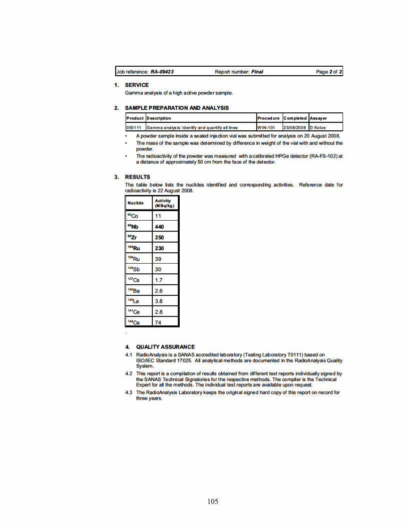
105