Embed Size (px)
Citation preview
7/27/2019 Radiographic Interpretation PPOINT
http://slidepdf.com/reader/full/radiographic-interpretation-ppoint 1/70
Radiographic Interpretation:
Anatomic Landmarks, Decay, &
Dental Materials
7/27/2019 Radiographic Interpretation PPOINT
http://slidepdf.com/reader/full/radiographic-interpretation-ppoint 2/70
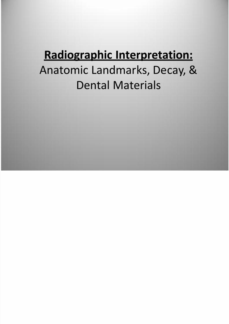
Radiographic Anatomy Basics:
The Tooth
7/27/2019 Radiographic Interpretation PPOINT
http://slidepdf.com/reader/full/radiographic-interpretation-ppoint 3/70
7/27/2019 Radiographic Interpretation PPOINT
http://slidepdf.com/reader/full/radiographic-interpretation-ppoint 4/70
7/27/2019 Radiographic Interpretation PPOINT
http://slidepdf.com/reader/full/radiographic-interpretation-ppoint 5/70
7/27/2019 Radiographic Interpretation PPOINT
http://slidepdf.com/reader/full/radiographic-interpretation-ppoint 6/70
7/27/2019 Radiographic Interpretation PPOINT
http://slidepdf.com/reader/full/radiographic-interpretation-ppoint 7/70
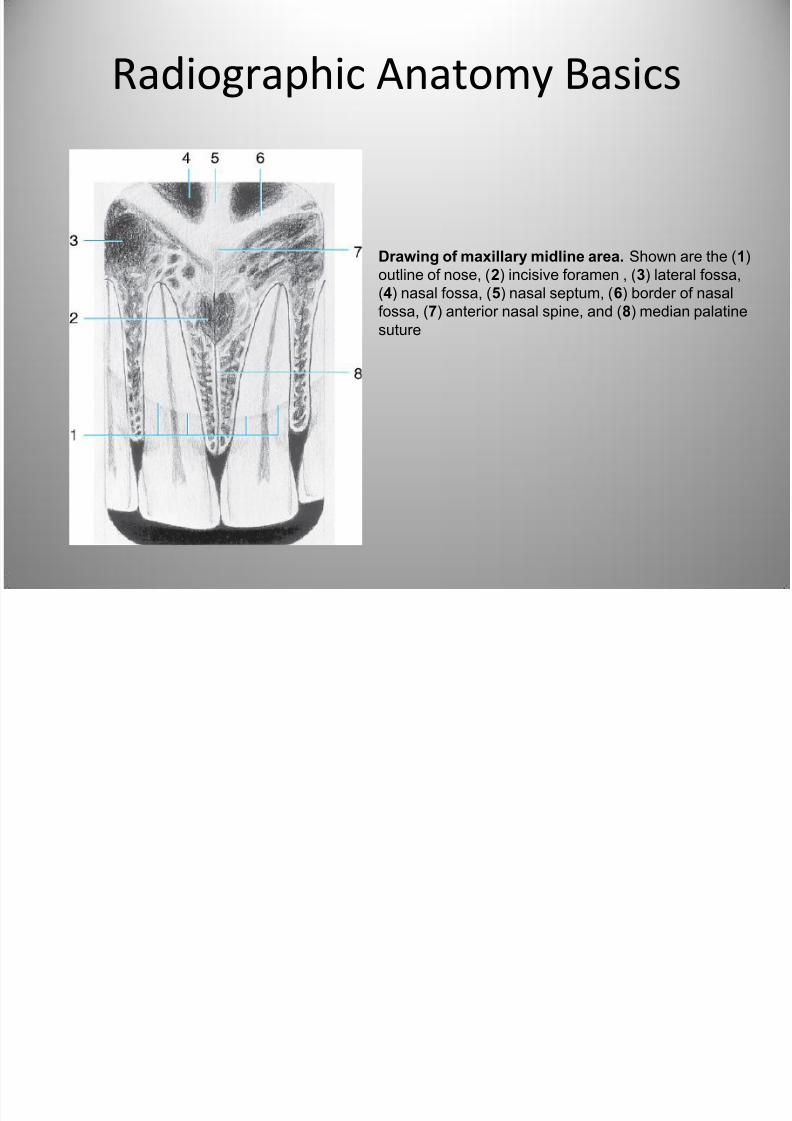
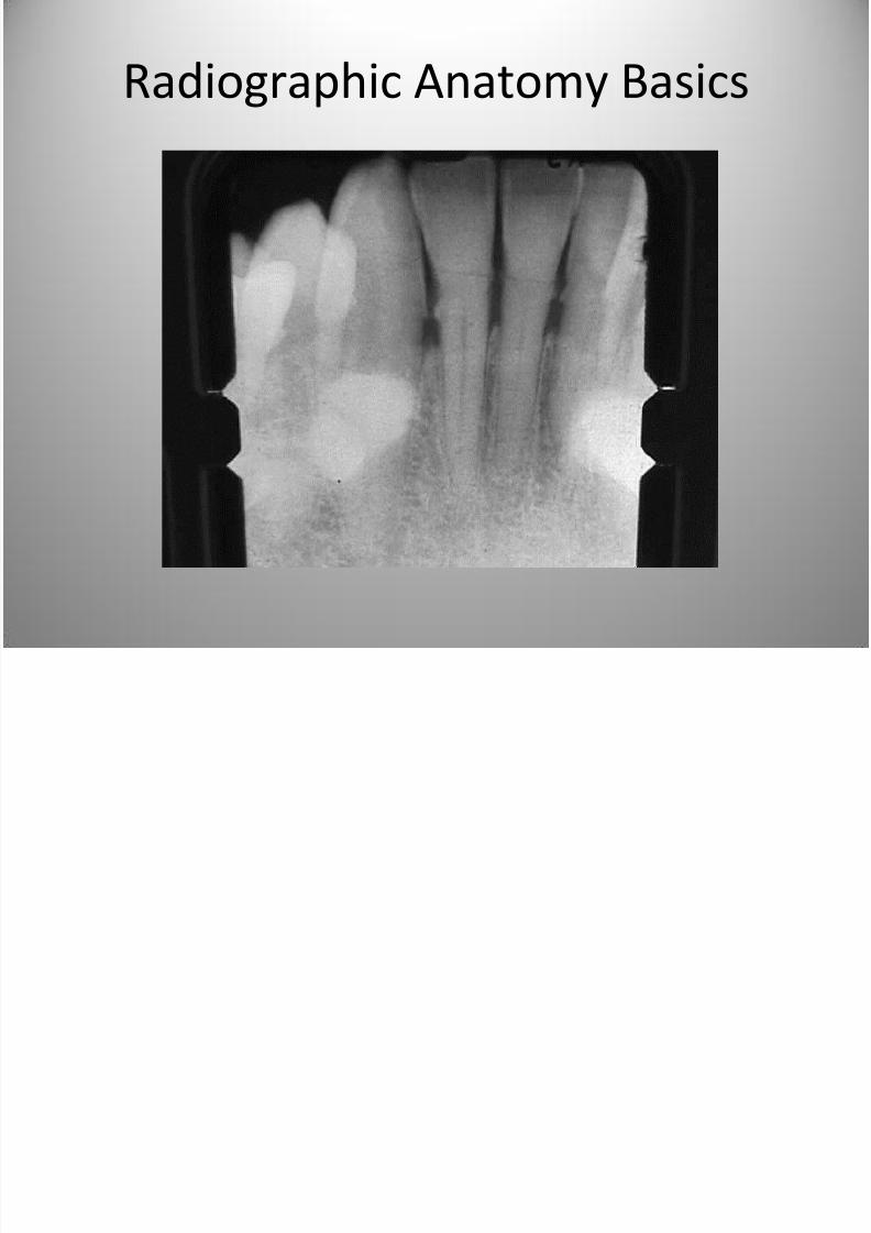
Radiographic Anatomy Basics
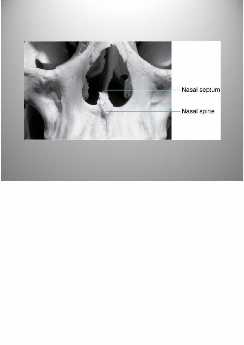
Drawing of maxillary midline area. Shown are the (1)
outline of nose, (2) incisive foramen , (3) lateral fossa,(4) nasal fossa, (5) nasal septum, (6) border of nasal
fossa, (7) anterior nasal spine, and (8) median palatine
suture
7/27/2019 Radiographic Interpretation PPOINT
http://slidepdf.com/reader/full/radiographic-interpretation-ppoint 8/70
7/27/2019 Radiographic Interpretation PPOINT
http://slidepdf.com/reader/full/radiographic-interpretation-ppoint 9/70
Radiographic Anatomy Basics
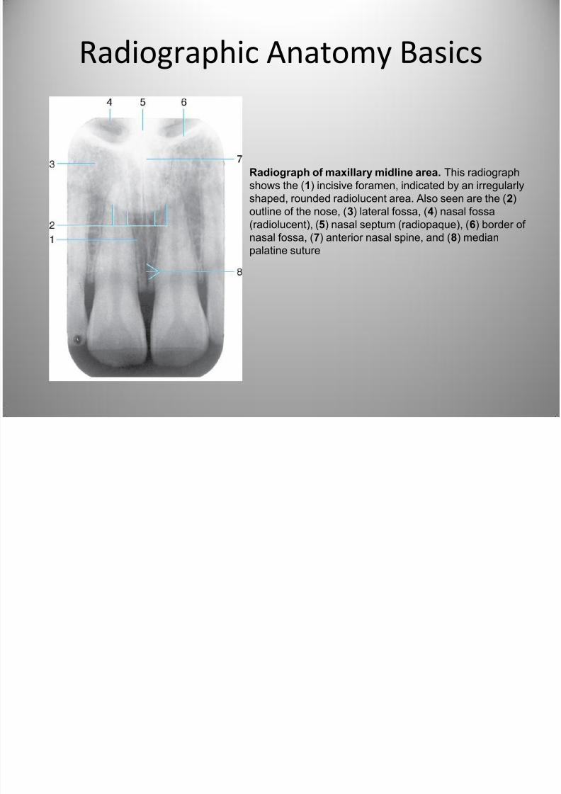
Radiograph of maxillary midline area. This radiograph
shows the (1) incisive foramen, indicated by an irregularly
shaped, rounded radiolucent area. Also seen are the (2)outline of the nose, (3) lateral fossa, (4) nasal fossa
(radiolucent), (5) nasal septum (radiopaque), (6) border of
nasal fossa, (7) anterior nasal spine, and (8) median
palatine suture
7/27/2019 Radiographic Interpretation PPOINT
http://slidepdf.com/reader/full/radiographic-interpretation-ppoint 10/70
Radiographic Anatomy Basics
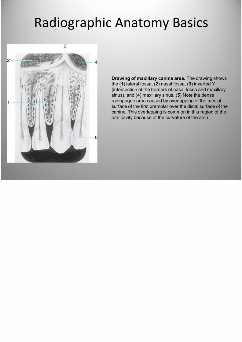
Drawing of maxillary canine area. The drawing shows
the (1) lateral fossa, (2) nasal fossa, (3) inverted Y(intersection of the borders of nasal fossa and maxillary
sinus), and (4) maxillary sinus. (5) Note the dense
radiopaque area caused by overlapping of the mesial
surface of the first premolar over the distal surface of the
canine. This overlapping is common in this region of the
oral cavity because of the curvature of the arch.
7/27/2019 Radiographic Interpretation PPOINT
http://slidepdf.com/reader/full/radiographic-interpretation-ppoint 11/70
Radiographic Anatomy Basics
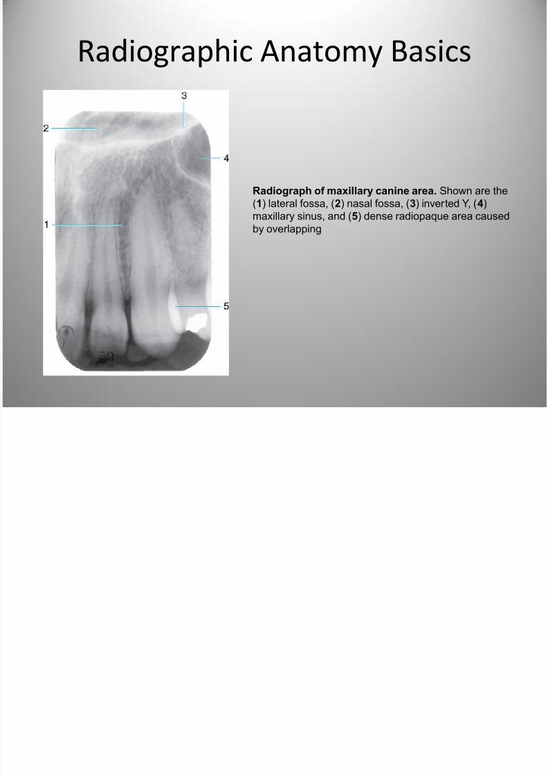
Radiograph of maxillary canine area. Shown are the(1) lateral fossa, (2) nasal fossa, (3) inverted Y, (4)
maxillary sinus, and (5) dense radiopaque area caused
by overlapping
7/27/2019 Radiographic Interpretation PPOINT
http://slidepdf.com/reader/full/radiographic-interpretation-ppoint 12/70
Radiographic Anatomy Basics
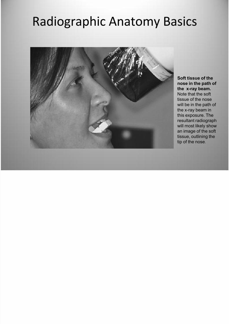
Soft tissue of thenose in the path of
the x-ray beam.
Note that the soft
tissue of the nose
will be in the path of
the x-ray beam in
this exposure. The
resultant radiographwill most likely show
an image of the soft
tissue, outlining the
tip of the nose.
7/27/2019 Radiographic Interpretation PPOINT
http://slidepdf.com/reader/full/radiographic-interpretation-ppoint 13/70
Radiographic Anatomy Basics
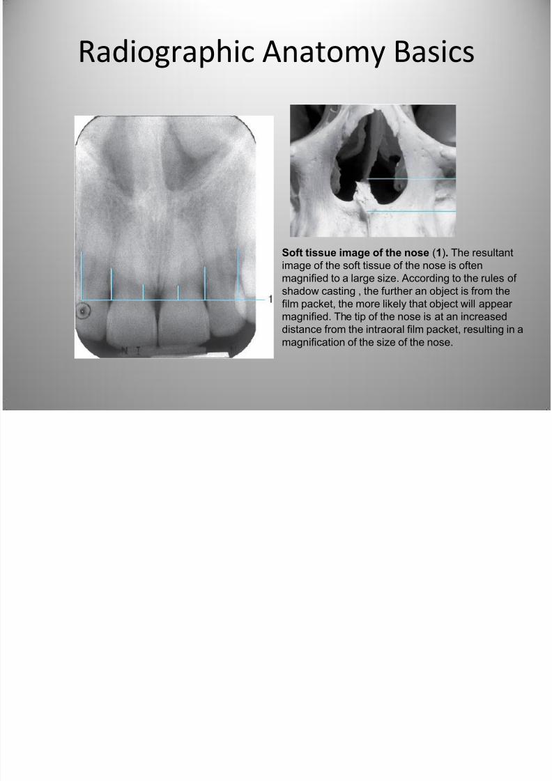
Soft tissue image of the nose (1). The resultant
image of the soft tissue of the nose is often
magnified to a large size. According to the rules of
shadow casting , the further an object is from thefilm packet, the more likely that object will appear
magnified. The tip of the nose is at an increased
distance from the intraoral film packet, resulting in a
magnification of the size of the nose.
7/27/2019 Radiographic Interpretation PPOINT
http://slidepdf.com/reader/full/radiographic-interpretation-ppoint 14/70
Radiographic Anatomy Basics
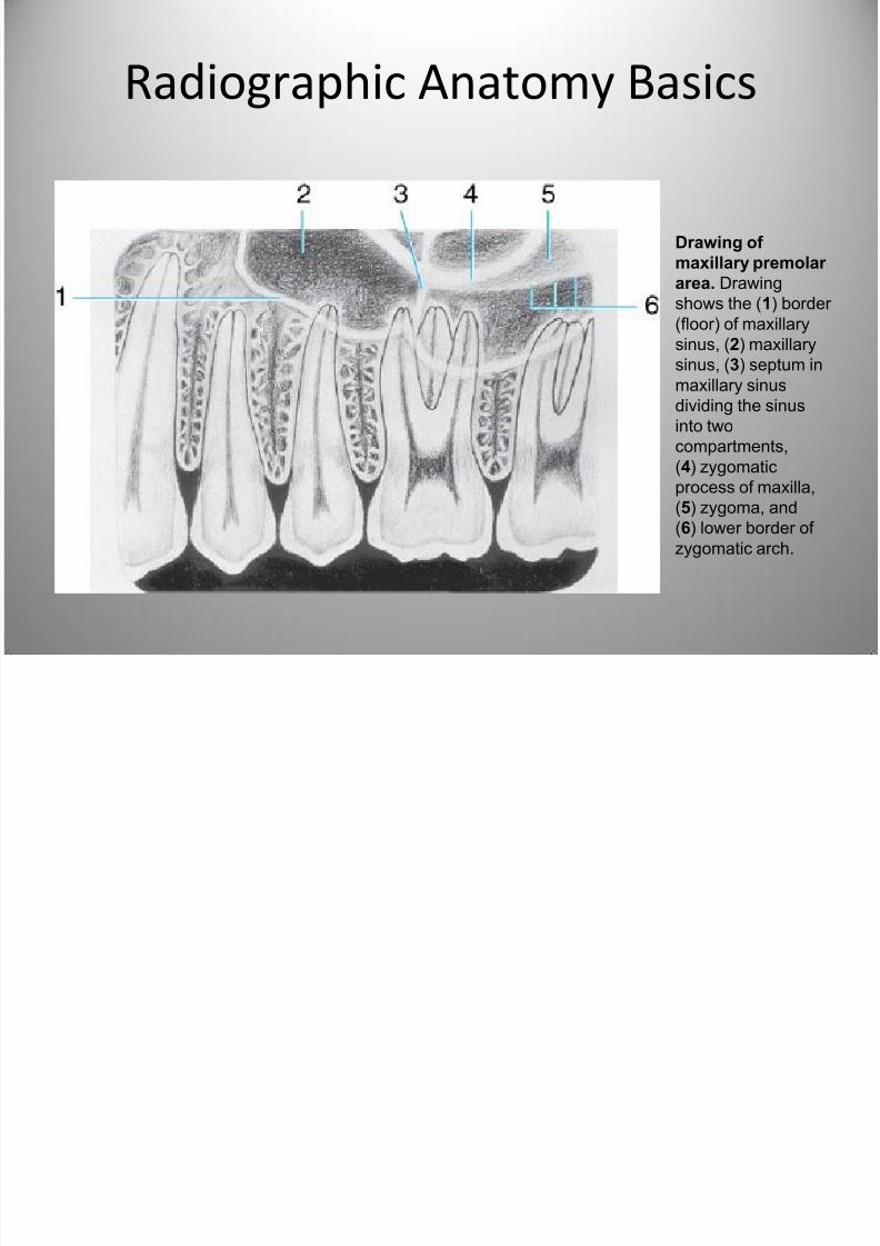
Drawing of
maxillary premolar
area. Drawing
shows the (1) border (floor) of maxillary
sinus, (2) maxillary
sinus, (3) septum in
maxillary sinus
dividing the sinus
into two
compartments,
(4) zygomaticprocess of maxilla,
(5) zygoma, and
(6) lower border of
zygomatic arch.
7/27/2019 Radiographic Interpretation PPOINT
http://slidepdf.com/reader/full/radiographic-interpretation-ppoint 15/70
Radiographic Anatomy Basics
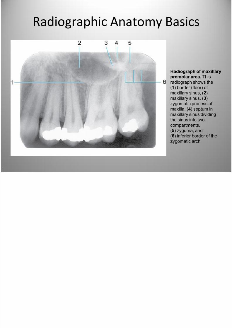
Radiograph of maxillary
premolar area. This
radiograph shows the(1) border (floor) of
maxillary sinus, (2)
maxillary sinus, (3)
zygomatic process of
maxilla, (4) septum in
maxillary sinus dividing
the sinus into twocompartments,
(5) zygoma, and
(6) inferior border of the
zygomatic arch
7/27/2019 Radiographic Interpretation PPOINT
http://slidepdf.com/reader/full/radiographic-interpretation-ppoint 16/70
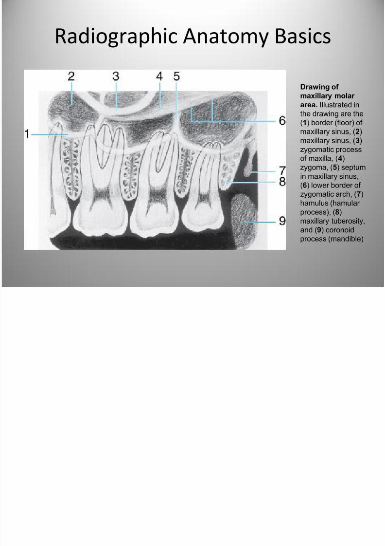
Radiographic Anatomy Basics
Drawing of
maxillary molar
area. Illustrated in
the drawing are the
(1) border (floor) of
maxillary sinus, (2)maxillary sinus, (3)
zygomatic process
of maxilla, (4)
zygoma, (5) septum
in maxillary sinus,
(6) lower border of
zygomatic arch, (7)
hamulus (hamular process), (8)
maxillary tuberosity,
and (9) coronoid
process (mandible)
7/27/2019 Radiographic Interpretation PPOINT
http://slidepdf.com/reader/full/radiographic-interpretation-ppoint 17/70
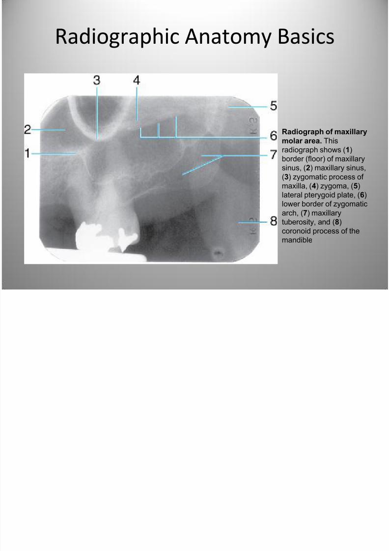
Radiographic Anatomy Basics
Radiograph of maxillary
molar area. This
radiograph shows (1)
border (floor) of maxillary
sinus, (2) maxillary sinus,
(3) zygomatic process of
maxilla, (4) zygoma, (5)
lateral pterygoid plate, (6)
lower border of zygomaticarch, (7) maxillary
tuberosity, and (8)
coronoid process of the
mandible
7/27/2019 Radiographic Interpretation PPOINT
http://slidepdf.com/reader/full/radiographic-interpretation-ppoint 18/70
7/27/2019 Radiographic Interpretation PPOINT
http://slidepdf.com/reader/full/radiographic-interpretation-ppoint 19/70
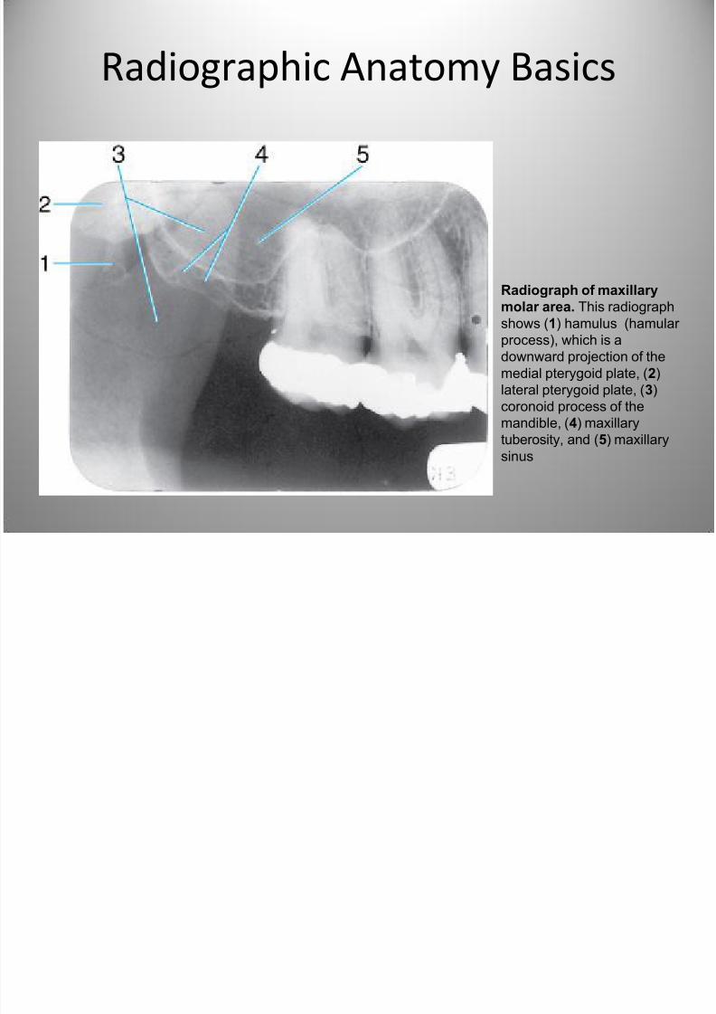
Radiographic Anatomy Basics
Radiograph of maxillary
molar area. This radiograph
shows (1) hamulus (hamular
process), which is a
downward projection of the
medial pterygoid plate, (2)lateral pterygoid plate, (3)
coronoid process of the
mandible, (4) maxillary
tuberosity, and (5) maxillary
sinus
7/27/2019 Radiographic Interpretation PPOINT
http://slidepdf.com/reader/full/radiographic-interpretation-ppoint 20/70
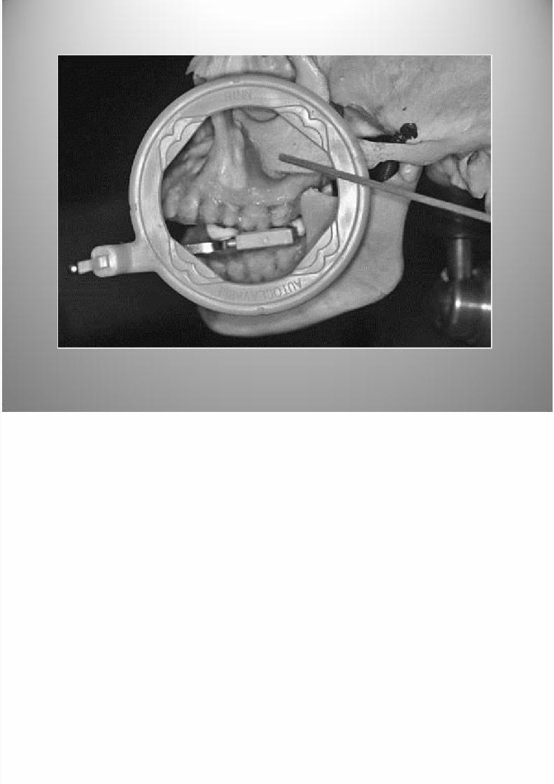
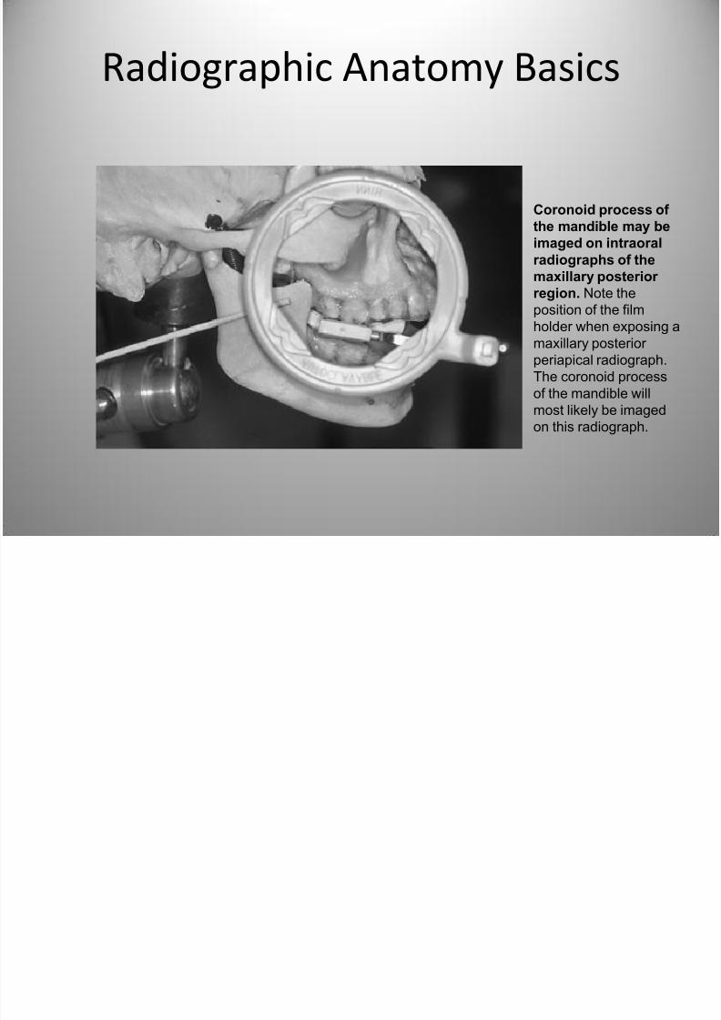
Radiographic Anatomy Basics
Coronoid process of
the mandible may be
imaged on intraoral
radiographs of the
maxillary posterior
region. Note the
position of the film
holder when exposing a
maxillary posterior
periapical radiograph.
The coronoid processof the mandible will
most likely be imaged
on this radiograph.
7/27/2019 Radiographic Interpretation PPOINT
http://slidepdf.com/reader/full/radiographic-interpretation-ppoint 21/70
Radiographic Anatomy Basics
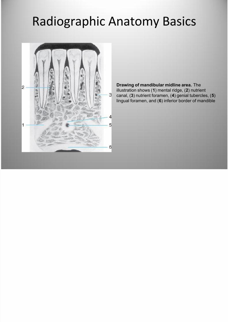
Drawing of mandibular midline area. The
illustration shows (1) mental ridge, (2) nutrient
canal, (3) nutrient foramen, (4) genial tubercles, (5)
lingual foramen, and (6) inferior border of mandible
7/27/2019 Radiographic Interpretation PPOINT
http://slidepdf.com/reader/full/radiographic-interpretation-ppoint 22/70
7/27/2019 Radiographic Interpretation PPOINT
http://slidepdf.com/reader/full/radiographic-interpretation-ppoint 23/70
Radiographic Anatomy Basics
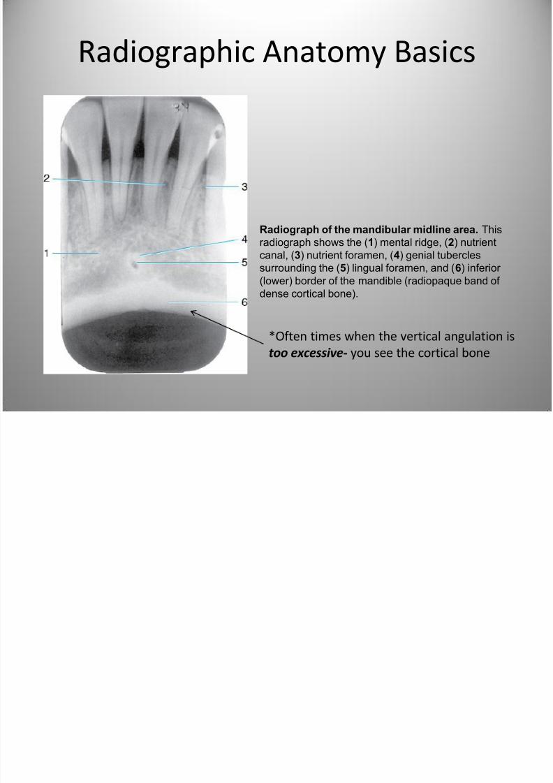
Radiograph of the mandibular midline area. This
radiograph shows the (1) mental ridge, (2) nutrient
canal, (3) nutrient foramen, (4) genial tubercles
surrounding the (5) lingual foramen, and (6) inferior
(lower) border of the mandible (radiopaque band of
dense cortical bone).
*Often times when the vertical angulation is
too excessive- you see the cortical bone
7/27/2019 Radiographic Interpretation PPOINT
http://slidepdf.com/reader/full/radiographic-interpretation-ppoint 24/70
Radiographic Anatomy Basics
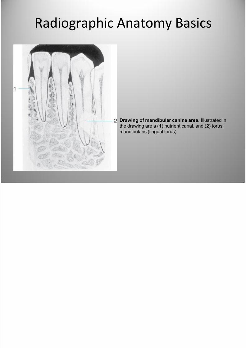
Drawing of mandibular canine area. Illustrated in
the drawing are a (1) nutrient canal, and (2) torus
mandibularis (lingual torus)
7/27/2019 Radiographic Interpretation PPOINT
http://slidepdf.com/reader/full/radiographic-interpretation-ppoint 25/70
Radiographic Anatomy Basics
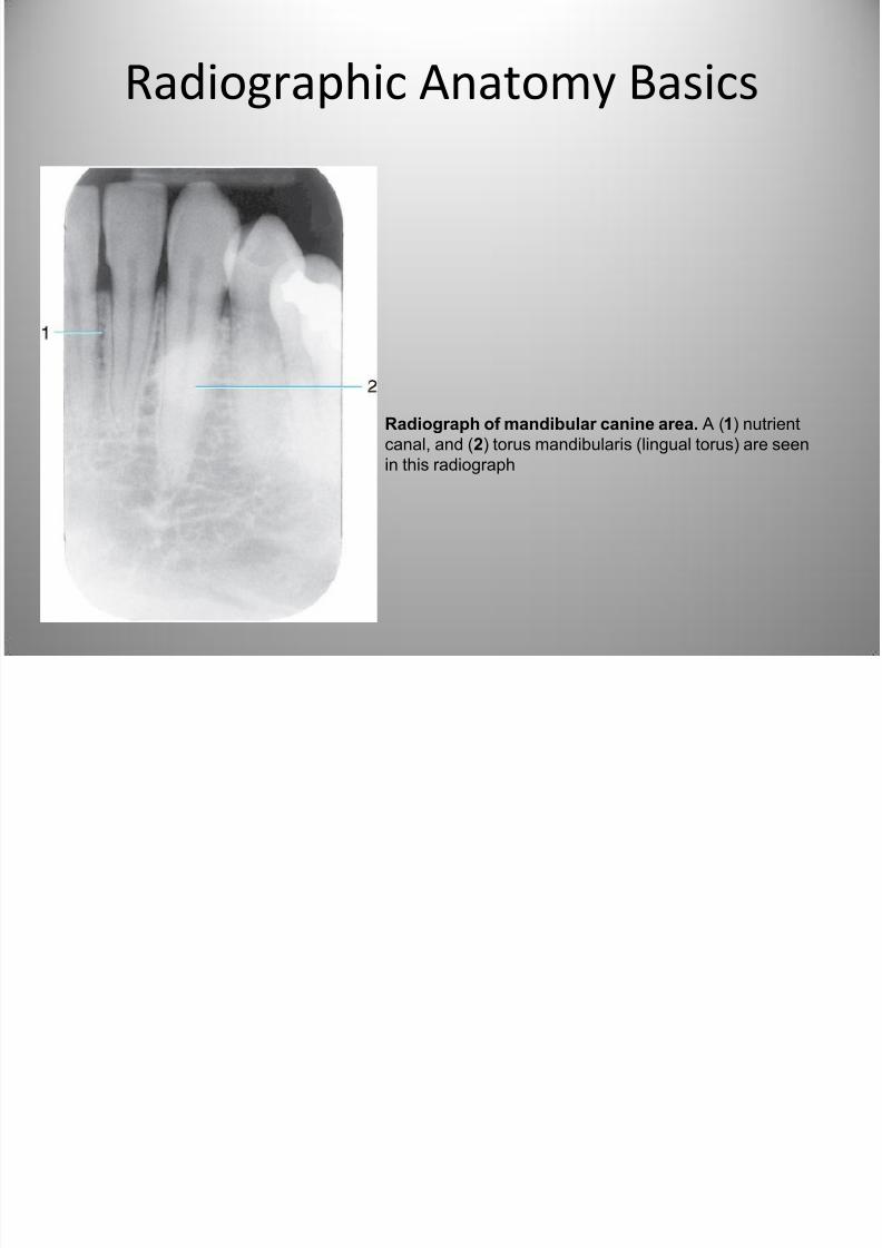
Radiograph of mandibular canine area. A (1) nutrient
canal, and (2) torus mandibularis (lingual torus) are seen
in this radiograph
7/27/2019 Radiographic Interpretation PPOINT
http://slidepdf.com/reader/full/radiographic-interpretation-ppoint 26/70
Radiographic Anatomy Basics
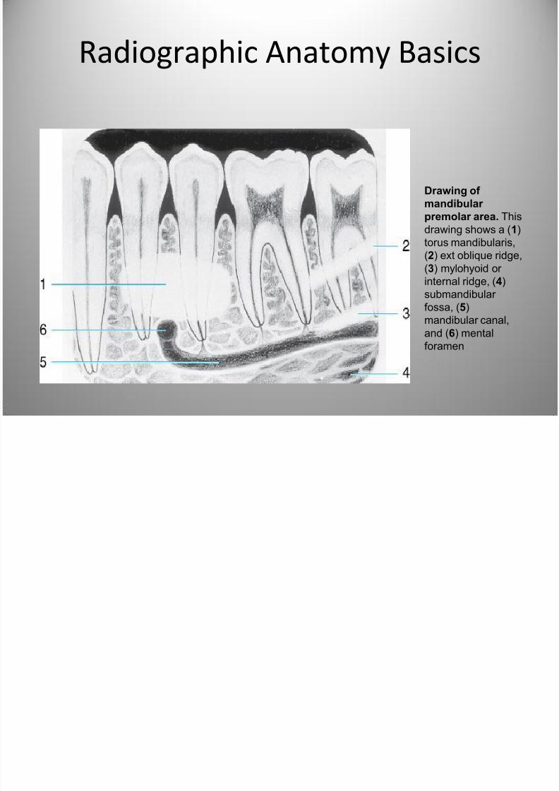
Drawing of
mandibular
premolar area. This
drawing shows a (1)
torus mandibularis,
(2) ext oblique ridge,
(3) mylohyoid or
internal ridge, (4)
submandibular fossa, (5)
mandibular canal,
and (6) mental
foramen
7/27/2019 Radiographic Interpretation PPOINT
http://slidepdf.com/reader/full/radiographic-interpretation-ppoint 27/70
Radiographic Anatomy Basics
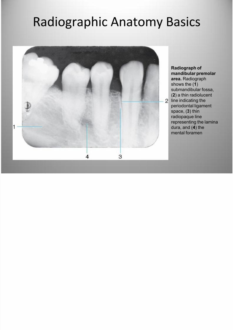
Radiograph of
mandibular premolar
area. Radiograph
shows the (1)submandibular fossa,
(2) a thin radiolucent
line indicating the
periodontal ligament
space, (3) thin
radiopaque line
representing the laminadura, and (4) the
mental foramen
7/27/2019 Radiographic Interpretation PPOINT
http://slidepdf.com/reader/full/radiographic-interpretation-ppoint 28/70
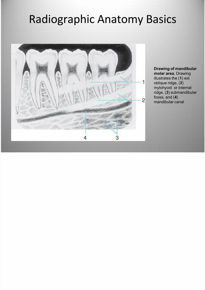
Radiographic Anatomy Basics
Drawing of mandibular
molar area. Drawingillustrates the (1) ext
oblique ridge, (2)
mylohyoid or internal
ridge, (3) submandibular
fossa, and (4)
mandibular canal
7/27/2019 Radiographic Interpretation PPOINT
http://slidepdf.com/reader/full/radiographic-interpretation-ppoint 29/70
7/27/2019 Radiographic Interpretation PPOINT
http://slidepdf.com/reader/full/radiographic-interpretation-ppoint 30/70
7/27/2019 Radiographic Interpretation PPOINT
http://slidepdf.com/reader/full/radiographic-interpretation-ppoint 31/70
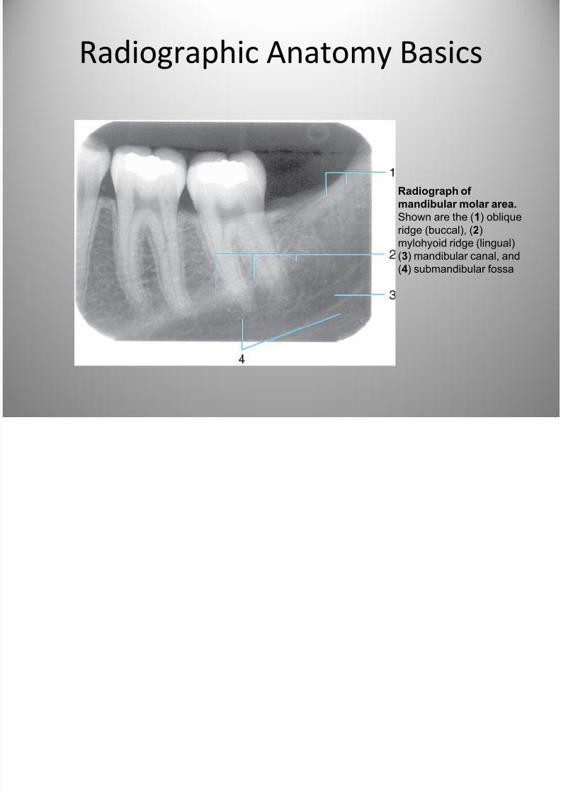
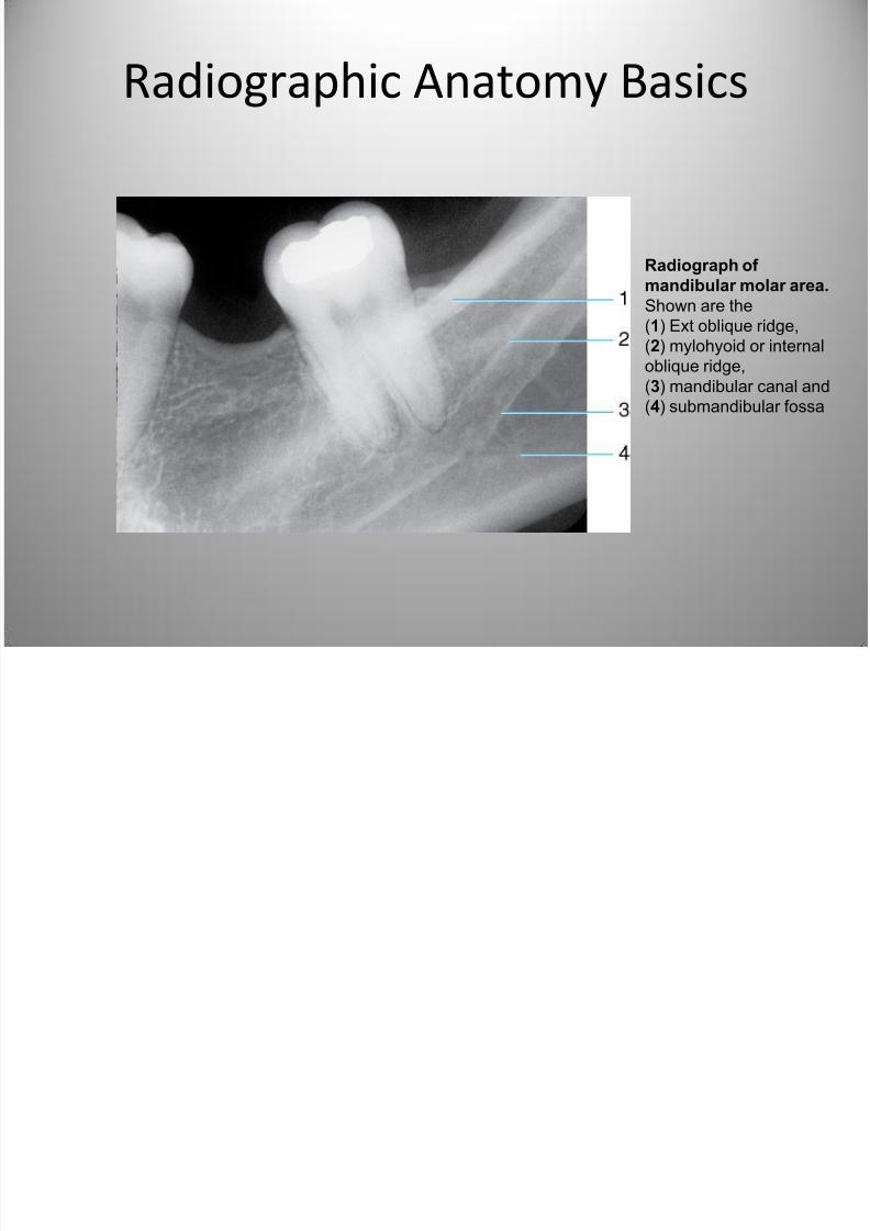
Radiographic Anatomy Basics
Radiograph of
mandibular molar area.
Shown are the(1) Ext oblique ridge,
(2) mylohyoid or internal
oblique ridge,
(3) mandibular canal and
(4) submandibular fossa
7/27/2019 Radiographic Interpretation PPOINT
http://slidepdf.com/reader/full/radiographic-interpretation-ppoint 32/70
Radiographic Anatomy Basics
7/27/2019 Radiographic Interpretation PPOINT
http://slidepdf.com/reader/full/radiographic-interpretation-ppoint 33/70
7/27/2019 Radiographic Interpretation PPOINT
http://slidepdf.com/reader/full/radiographic-interpretation-ppoint 34/70
7/27/2019 Radiographic Interpretation PPOINT
http://slidepdf.com/reader/full/radiographic-interpretation-ppoint 35/70
7/27/2019 Radiographic Interpretation PPOINT
http://slidepdf.com/reader/full/radiographic-interpretation-ppoint 36/70
7/27/2019 Radiographic Interpretation PPOINT
http://slidepdf.com/reader/full/radiographic-interpretation-ppoint 37/70
7/27/2019 Radiographic Interpretation PPOINT
http://slidepdf.com/reader/full/radiographic-interpretation-ppoint 38/70
7/27/2019 Radiographic Interpretation PPOINT
http://slidepdf.com/reader/full/radiographic-interpretation-ppoint 39/70
7/27/2019 Radiographic Interpretation PPOINT
http://slidepdf.com/reader/full/radiographic-interpretation-ppoint 40/70
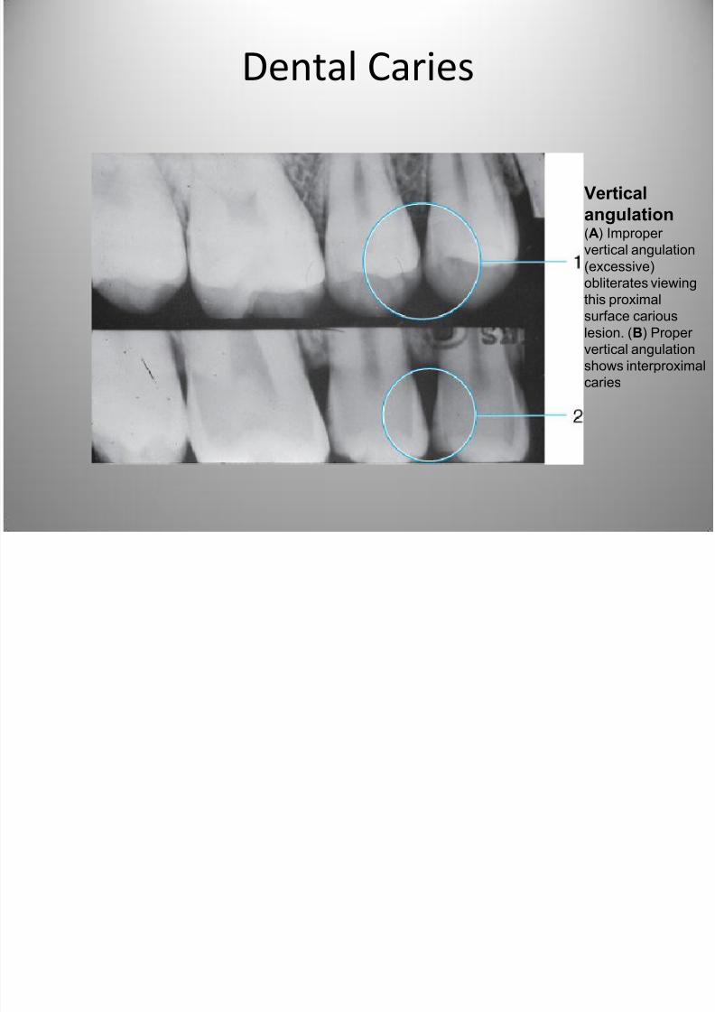
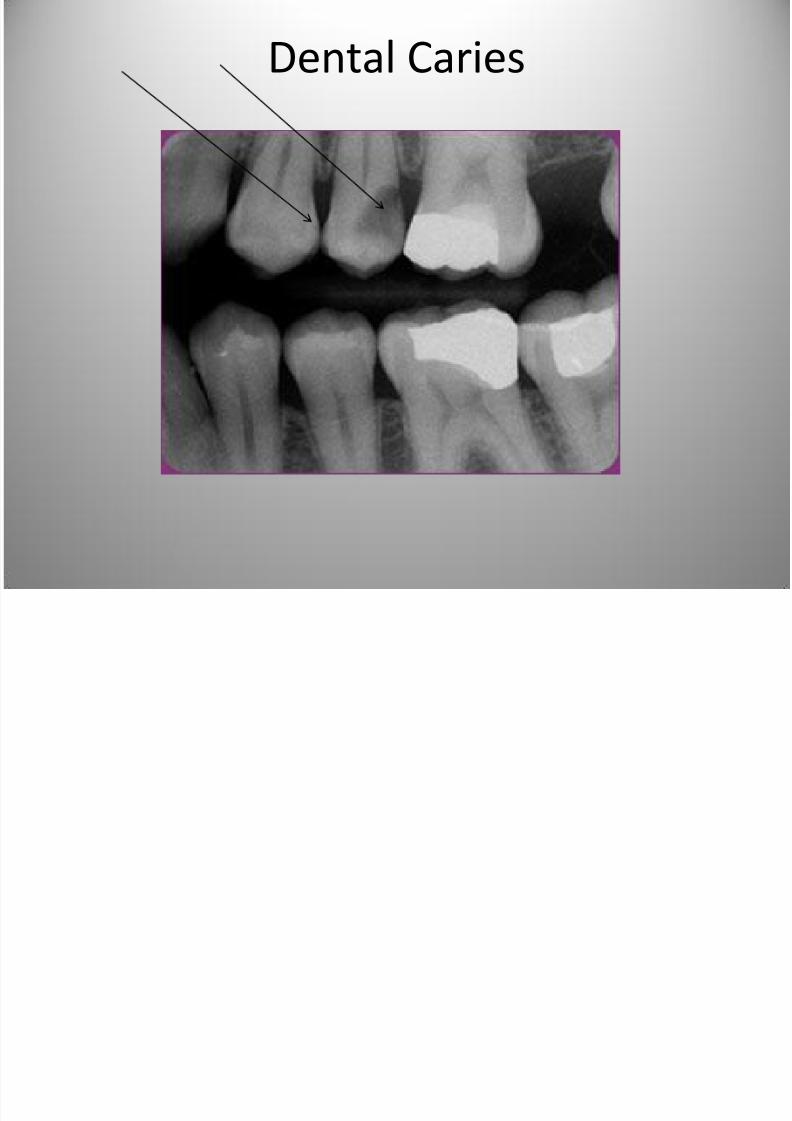
Dental Caries
Vertical
angulation (A) Improper
vertical angulation(excessive)
obliterates viewing
this proximal
surface carious
lesion. (B) Proper
vertical angulation
shows interproximal
caries
7/27/2019 Radiographic Interpretation PPOINT
http://slidepdf.com/reader/full/radiographic-interpretation-ppoint 41/70
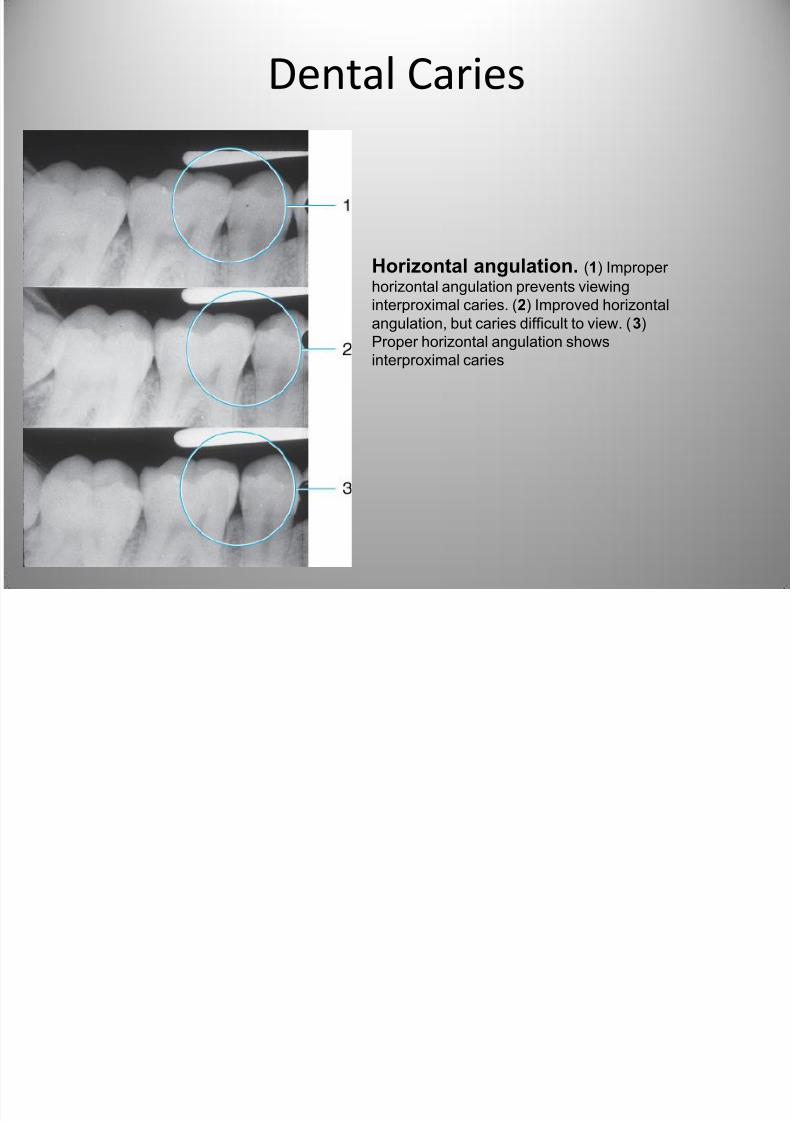
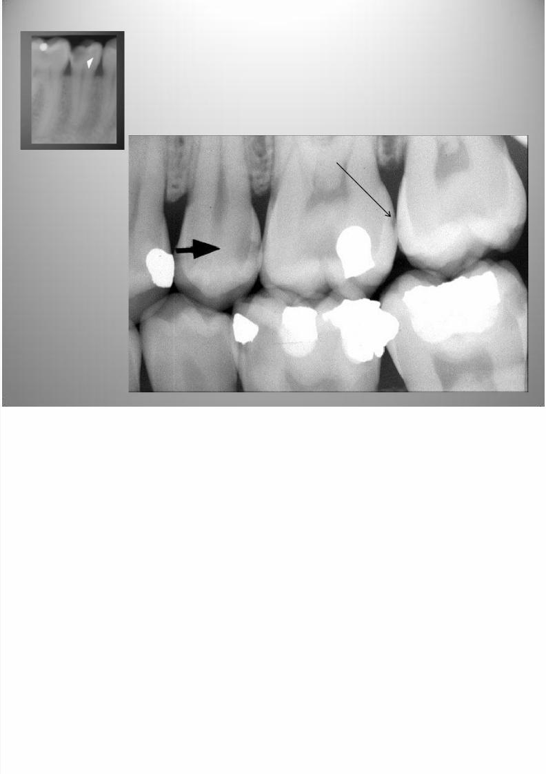
Dental Caries
Horizontal angulation. (1) Improper
horizontal angulation prevents viewinginterproximal caries. (2) Improved horizontal
angulation, but caries difficult to view. (3)
Proper horizontal angulation shows
interproximal caries
7/27/2019 Radiographic Interpretation PPOINT
http://slidepdf.com/reader/full/radiographic-interpretation-ppoint 42/70
Dental Caries
7/27/2019 Radiographic Interpretation PPOINT
http://slidepdf.com/reader/full/radiographic-interpretation-ppoint 43/70
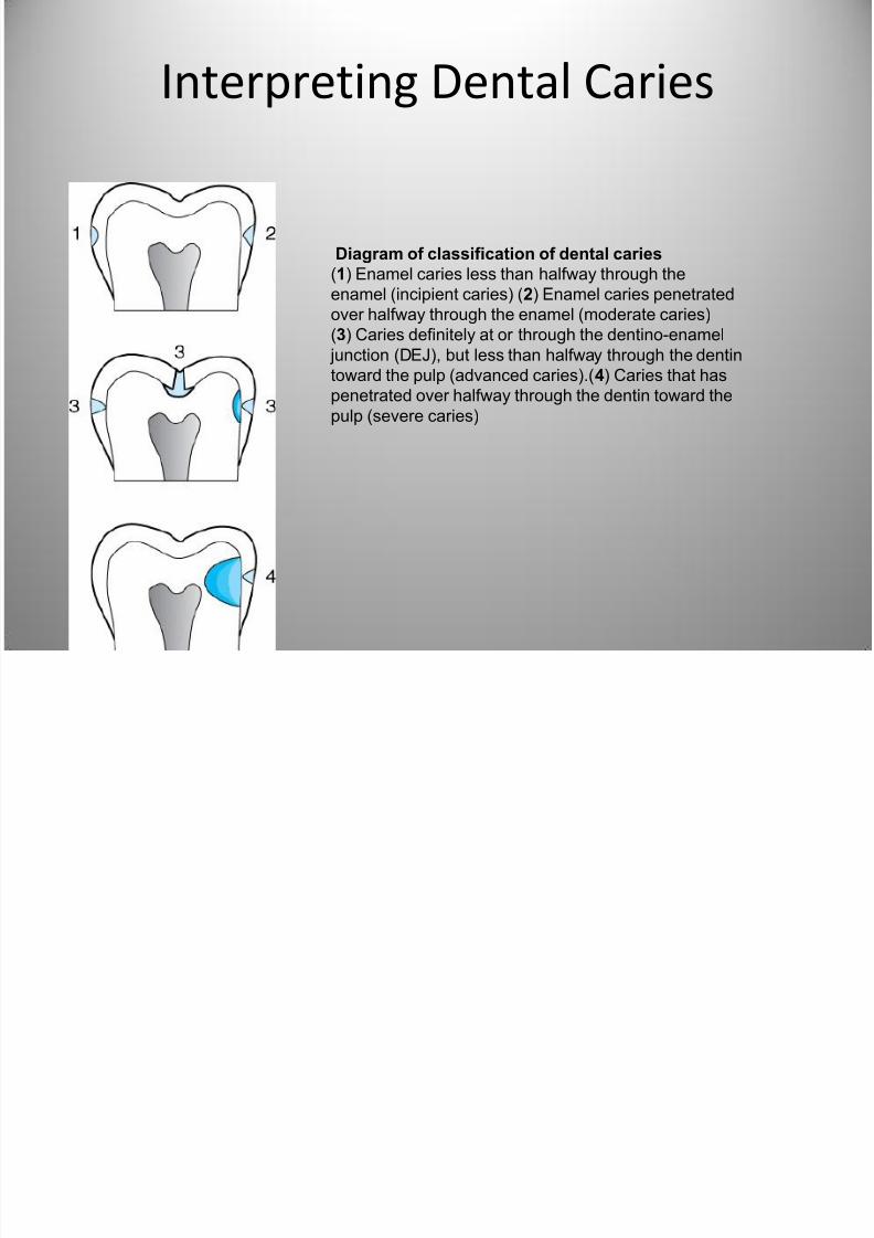
Interpreting Dental Caries
Diagram of classification of dental caries
(1) Enamel caries less than halfway through the
enamel (incipient caries) (2) Enamel caries penetrated
over halfway through the enamel (moderate caries)(3) Caries definitely at or through the dentino-enamel
junction (DEJ), but less than halfway through the dentin
toward the pulp (advanced caries).(4) Caries that has
penetrated over halfway through the dentin toward the
pulp (severe caries)
7/27/2019 Radiographic Interpretation PPOINT
http://slidepdf.com/reader/full/radiographic-interpretation-ppoint 44/70
Dental Caries
7/27/2019 Radiographic Interpretation PPOINT
http://slidepdf.com/reader/full/radiographic-interpretation-ppoint 45/70
7/27/2019 Radiographic Interpretation PPOINT
http://slidepdf.com/reader/full/radiographic-interpretation-ppoint 46/70
7/27/2019 Radiographic Interpretation PPOINT
http://slidepdf.com/reader/full/radiographic-interpretation-ppoint 47/70
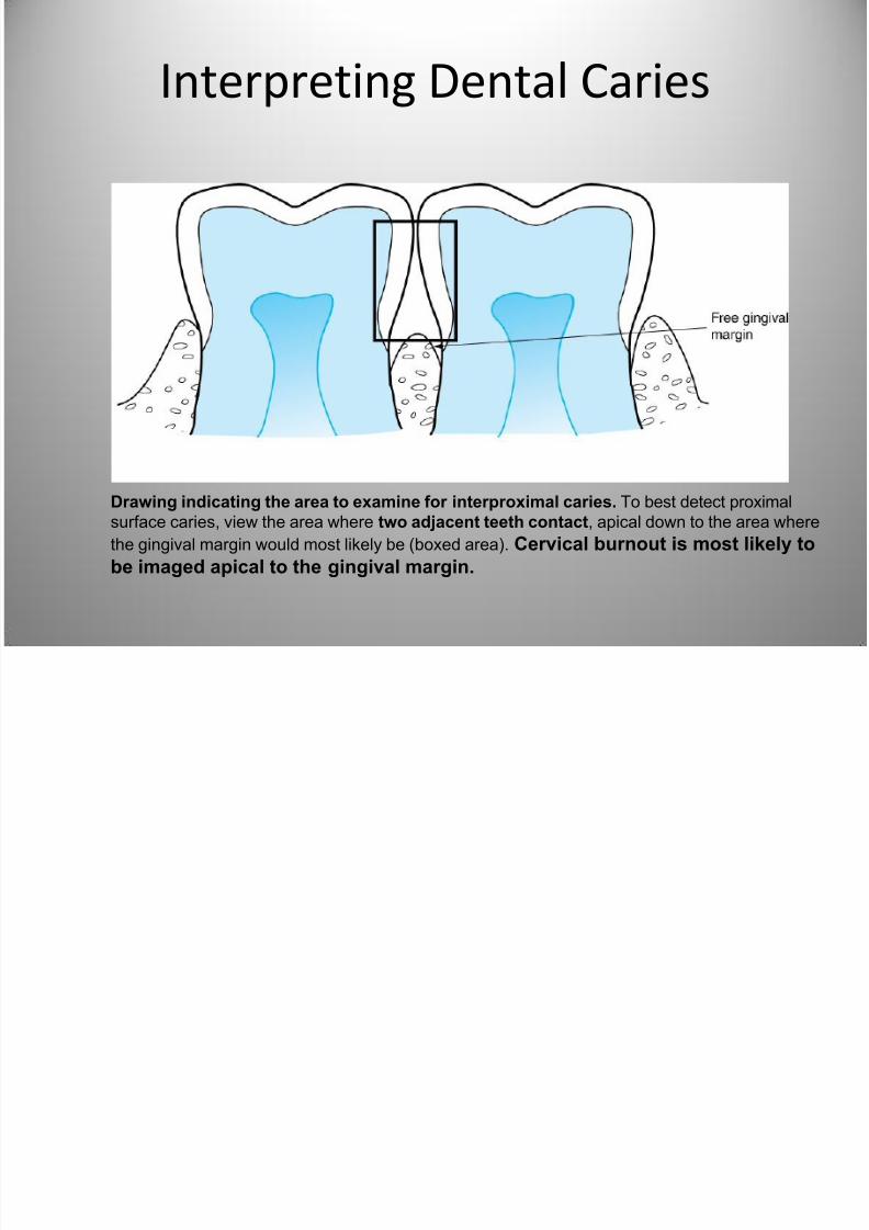
Interpreting Dental Caries
Drawing indicating the area to examine for interproximal caries. To best detect proximal
surface caries, view the area where two adjacent teeth contact, apical down to the area where
the gingival margin would most likely be (boxed area). Cervical burnout is most likely to
be imaged apical to the gingival margin.
7/27/2019 Radiographic Interpretation PPOINT
http://slidepdf.com/reader/full/radiographic-interpretation-ppoint 48/70
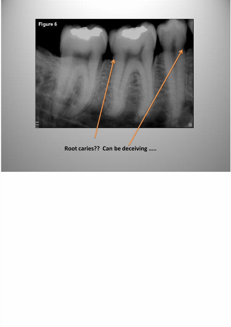
Root caries?? Can be deceiving …..
7/27/2019 Radiographic Interpretation PPOINT
http://slidepdf.com/reader/full/radiographic-interpretation-ppoint 49/70
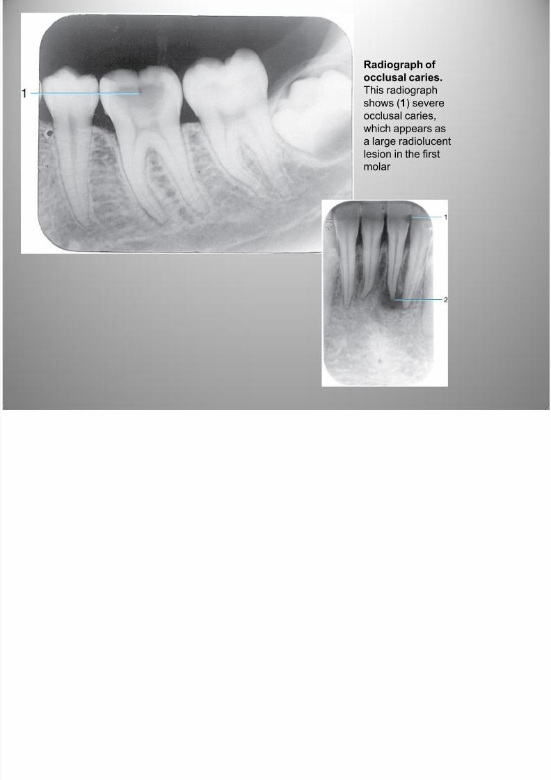
Radiograph of
occlusal caries.
This radiograph
shows (1) severeocclusal caries,
which appears as
a large radiolucent
lesion in the firstmolar
7/27/2019 Radiographic Interpretation PPOINT
http://slidepdf.com/reader/full/radiographic-interpretation-ppoint 50/70
Dental Caries
7/27/2019 Radiographic Interpretation PPOINT
http://slidepdf.com/reader/full/radiographic-interpretation-ppoint 51/70
Dental Caries
7/27/2019 Radiographic Interpretation PPOINT
http://slidepdf.com/reader/full/radiographic-interpretation-ppoint 52/70
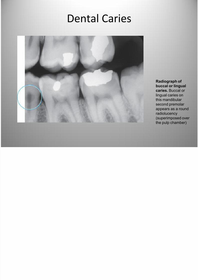
Radiograph of
buccal or lingual
caries. Buccal or
lingual caries on
this mandibular
second premolar appears as a round
radiolucency
(superimposed over
the pulp chamber)
Dental Caries
7/27/2019 Radiographic Interpretation PPOINT
http://slidepdf.com/reader/full/radiographic-interpretation-ppoint 53/70
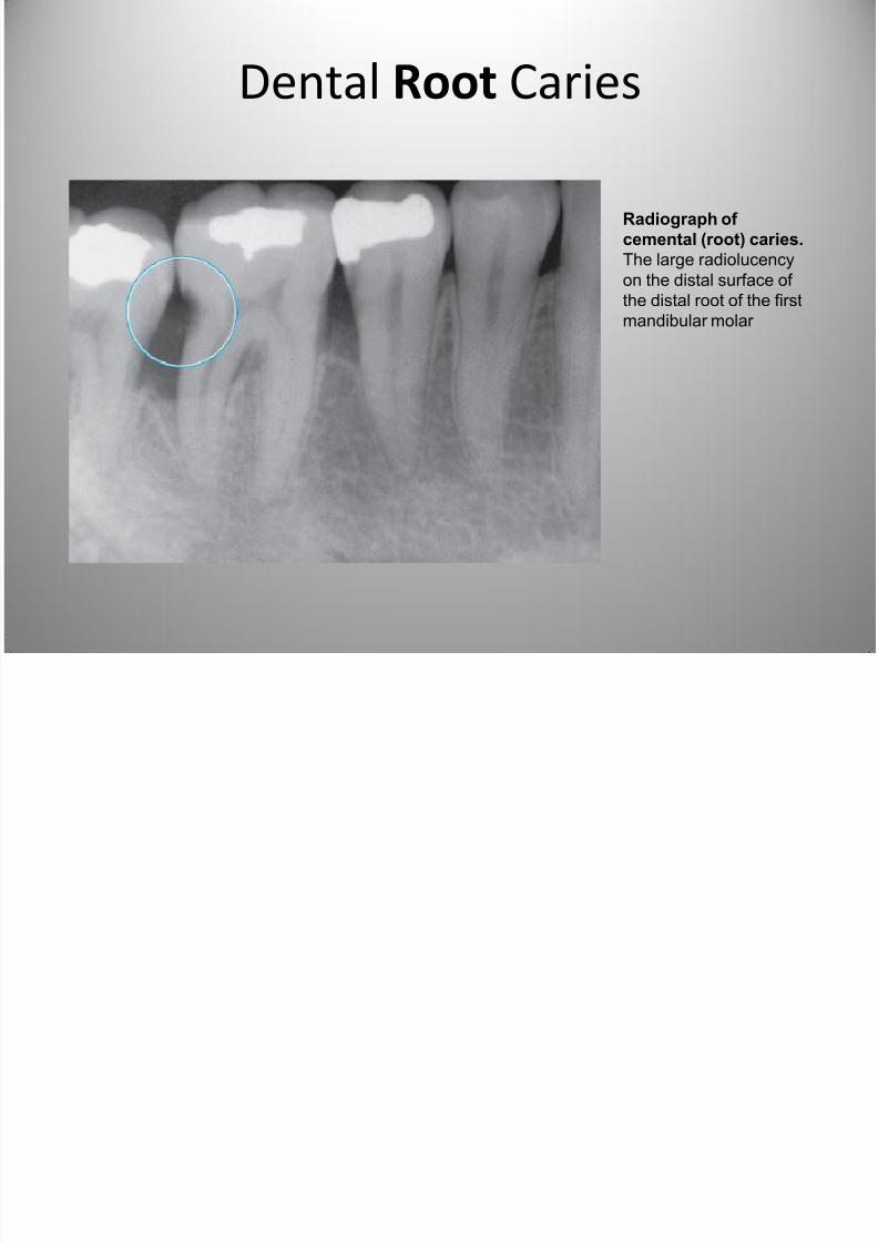
Radiograph of
cemental (root) caries.
The large radiolucency
on the distal surface of
the distal root of the first
mandibular molar
Dental Root Caries
7/27/2019 Radiographic Interpretation PPOINT
http://slidepdf.com/reader/full/radiographic-interpretation-ppoint 54/70
Dental Root Caries
7/27/2019 Radiographic Interpretation PPOINT
http://slidepdf.com/reader/full/radiographic-interpretation-ppoint 55/70
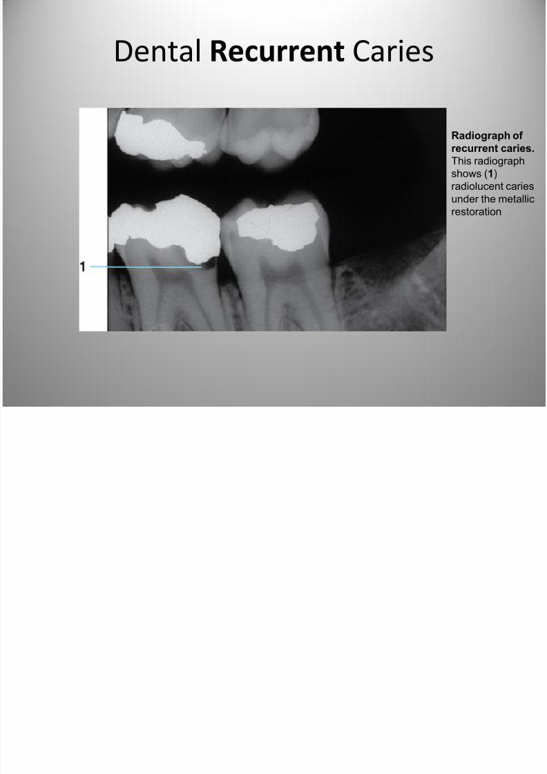
Radiograph of
recurrent caries.
This radiograph
shows (1)
radiolucent caries
under the metallicrestoration
Dental Recurrent Caries
7/27/2019 Radiographic Interpretation PPOINT
http://slidepdf.com/reader/full/radiographic-interpretation-ppoint 56/70
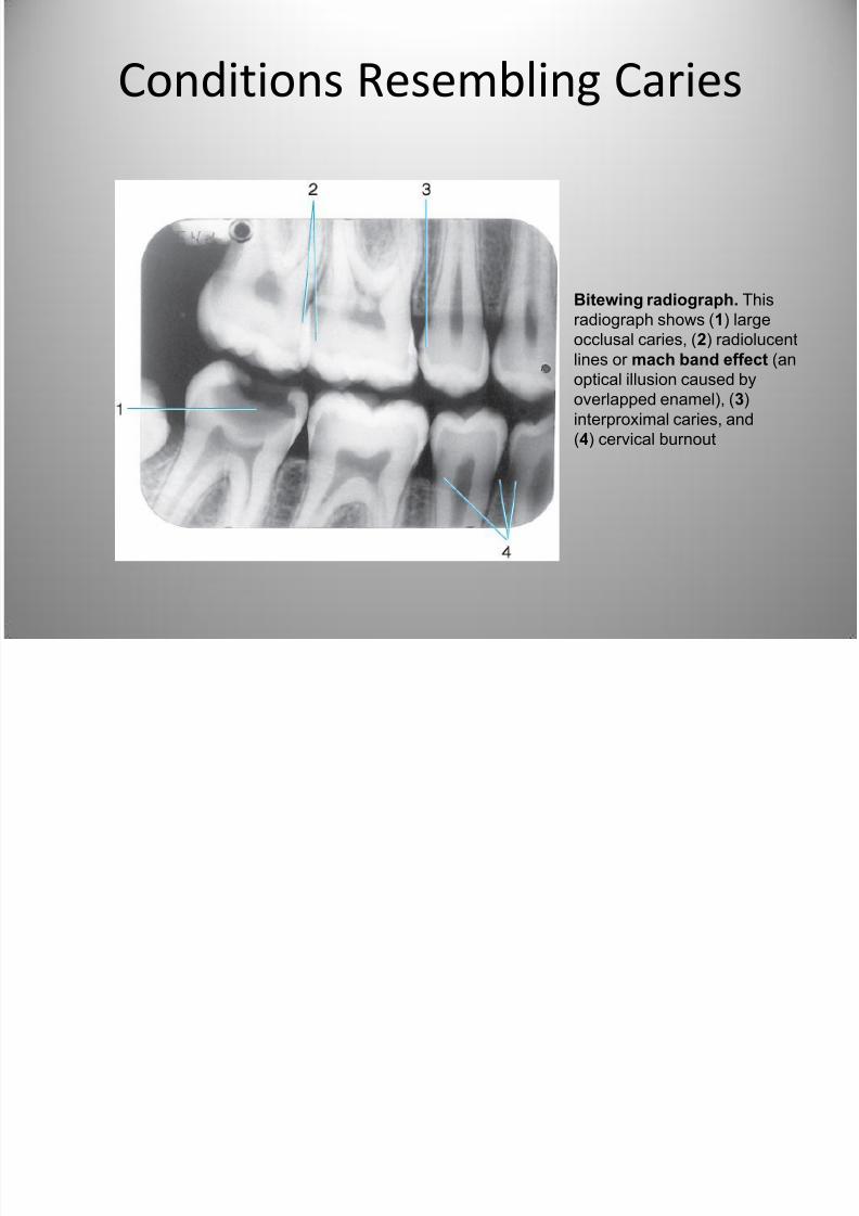
Conditions Resembling Caries
Bitewing radiograph. This
radiograph shows (1) large
occlusal caries, (2) radiolucent
lines or mach band effect (an
optical illusion caused by
overlapped enamel), (3)
interproximal caries, and
(4) cervical burnout
R di hi A f D t l
7/27/2019 Radiographic Interpretation PPOINT
http://slidepdf.com/reader/full/radiographic-interpretation-ppoint 57/70
Radiographic Appearance of Dental
Restorative Material
R di hi A f D t l
7/27/2019 Radiographic Interpretation PPOINT
http://slidepdf.com/reader/full/radiographic-interpretation-ppoint 58/70
Radiographic Appearance of Dental
Restorative Material
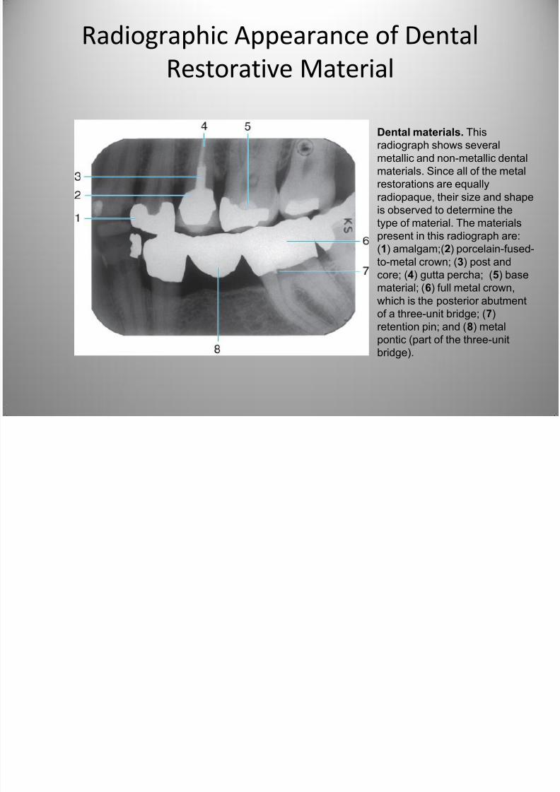
Dental materials. This
radiograph shows several
metallic and non-metallic dental
materials. Since all of the metal
restorations are equally
radiopaque, their size and shapeis observed to determine the
type of material. The materials
present in this radiograph are:
(1) amalgam;(2) porcelain-fused-
to-metal crown; (3) post and
core; (4) gutta percha; (5) base
material; (6) full metal crown,
which is the posterior abutmentof a three-unit bridge; (7)
retention pin; and (8) metal
pontic (part of the three-unit
bridge).
7/27/2019 Radiographic Interpretation PPOINT
http://slidepdf.com/reader/full/radiographic-interpretation-ppoint 59/70
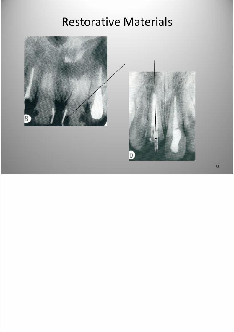
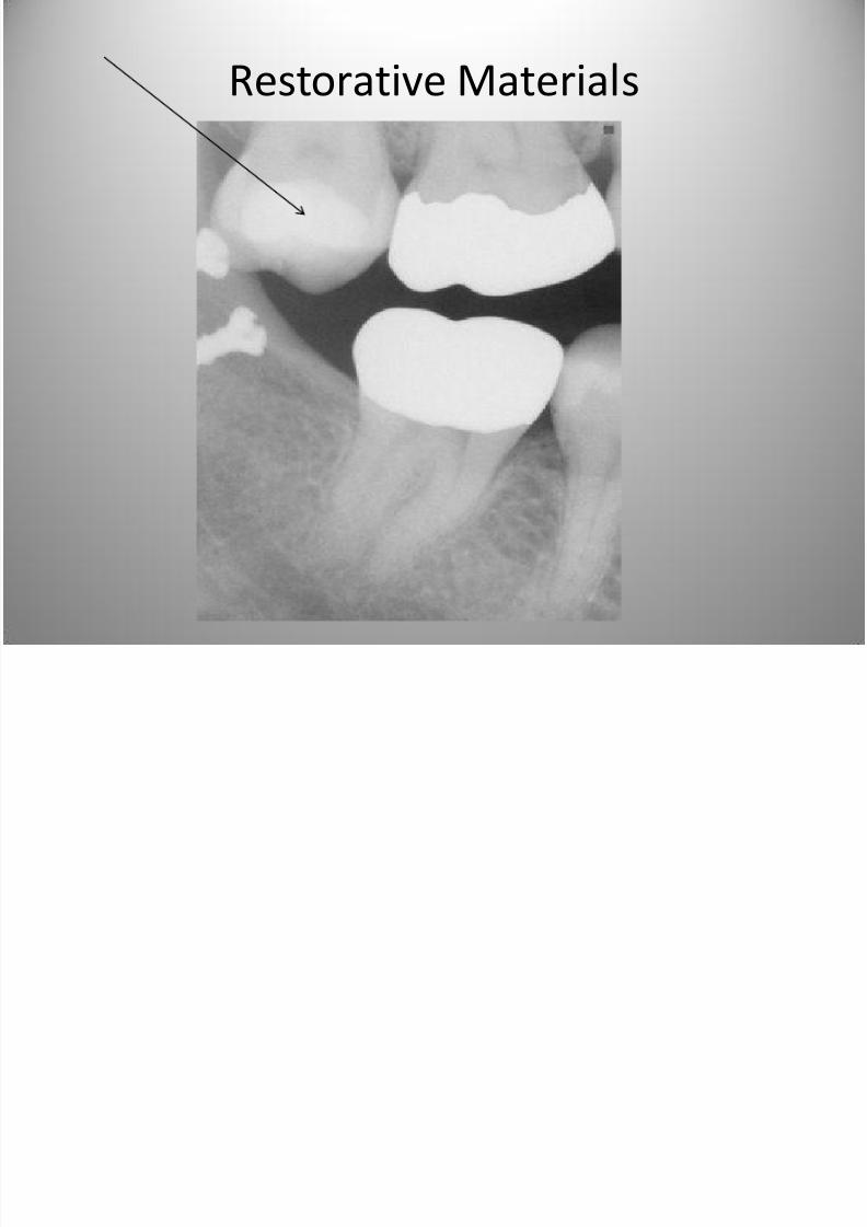
Restorative Materials
7/27/2019 Radiographic Interpretation PPOINT
http://slidepdf.com/reader/full/radiographic-interpretation-ppoint 60/70
Restorative Materials
7/27/2019 Radiographic Interpretation PPOINT
http://slidepdf.com/reader/full/radiographic-interpretation-ppoint 61/70
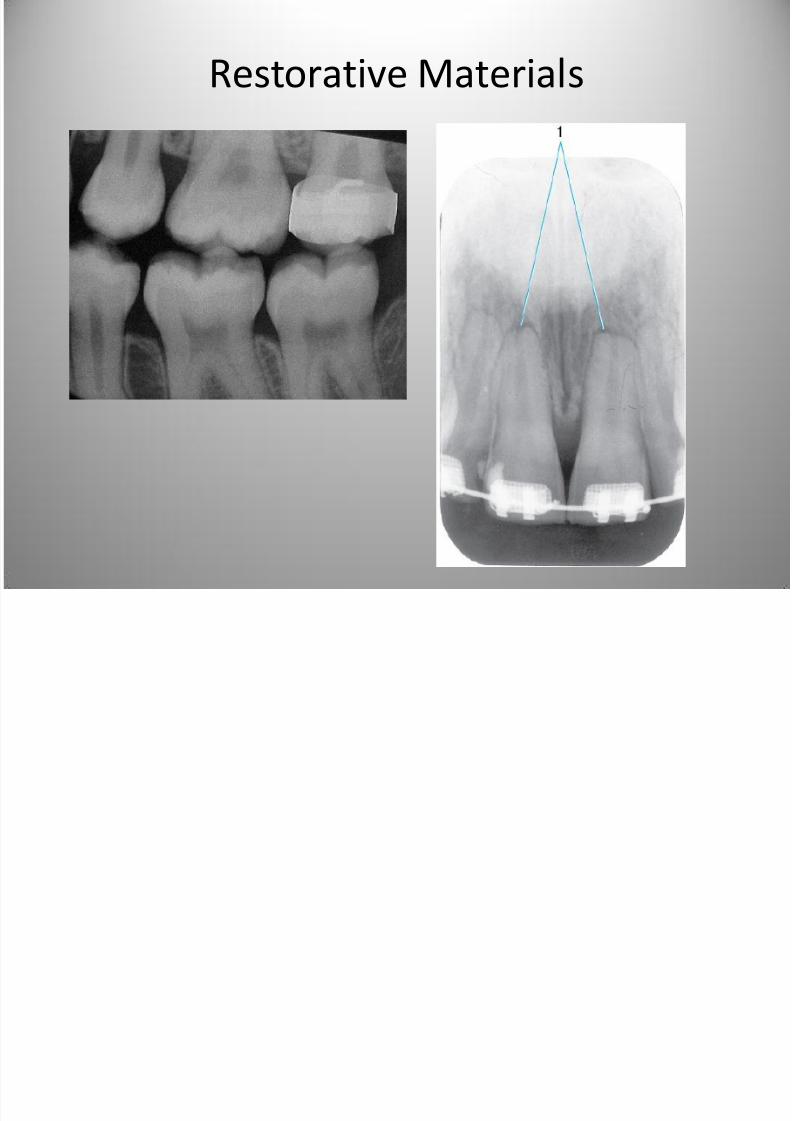
Restorative Materials
7/27/2019 Radiographic Interpretation PPOINT
http://slidepdf.com/reader/full/radiographic-interpretation-ppoint 62/70
Restorative Materials
7/27/2019 Radiographic Interpretation PPOINT
http://slidepdf.com/reader/full/radiographic-interpretation-ppoint 63/70
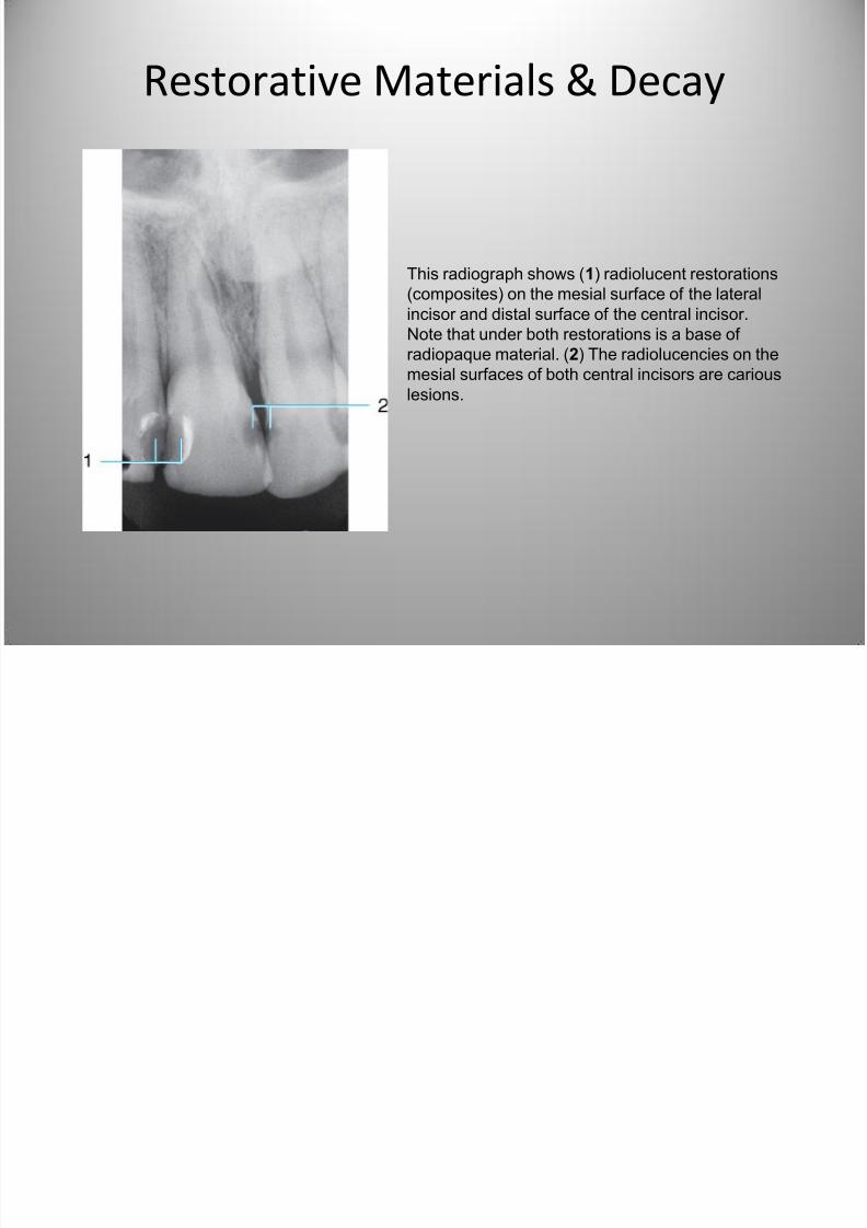
This radiograph shows (1) radiolucent restorations
(composites) on the mesial surface of the lateral
incisor and distal surface of the central incisor.Note that under both restorations is a base of
radiopaque material. (2) The radiolucencies on the
mesial surfaces of both central incisors are carious
lesions.
Restorative Materials & Decay
7/27/2019 Radiographic Interpretation PPOINT
http://slidepdf.com/reader/full/radiographic-interpretation-ppoint 64/70
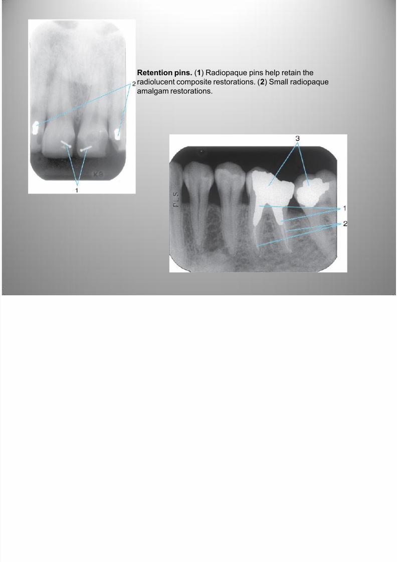
Retention pins. (1) Radiopaque pins help retain theradiolucent composite restorations. (2) Small radiopaque
amalgam restorations.
7/27/2019 Radiographic Interpretation PPOINT
http://slidepdf.com/reader/full/radiographic-interpretation-ppoint 65/70
65
Restorative Materials
7/27/2019 Radiographic Interpretation PPOINT
http://slidepdf.com/reader/full/radiographic-interpretation-ppoint 66/70
Restorative Materials
7/27/2019 Radiographic Interpretation PPOINT
http://slidepdf.com/reader/full/radiographic-interpretation-ppoint 67/70
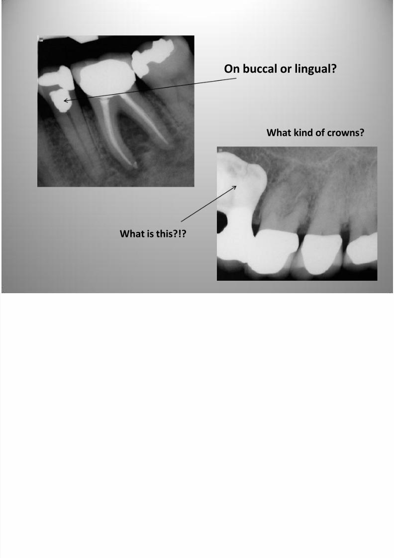
On buccal or lingual?
What kind of crowns?
What is this?!?
7/27/2019 Radiographic Interpretation PPOINT
http://slidepdf.com/reader/full/radiographic-interpretation-ppoint 68/70
Restorative Materials
7/27/2019 Radiographic Interpretation PPOINT
http://slidepdf.com/reader/full/radiographic-interpretation-ppoint 69/70
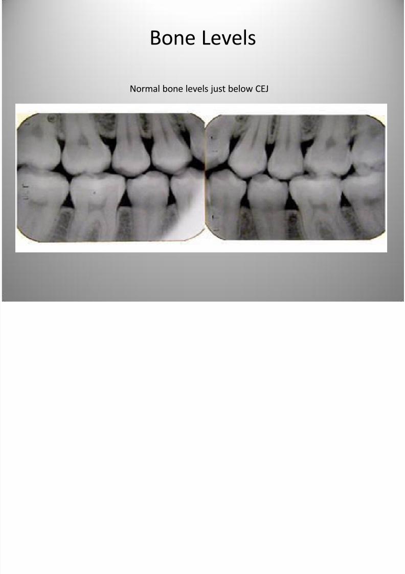
Normal bone levels just below CEJ
Bone Levels
B L l
7/27/2019 Radiographic Interpretation PPOINT
http://slidepdf.com/reader/full/radiographic-interpretation-ppoint 70/70
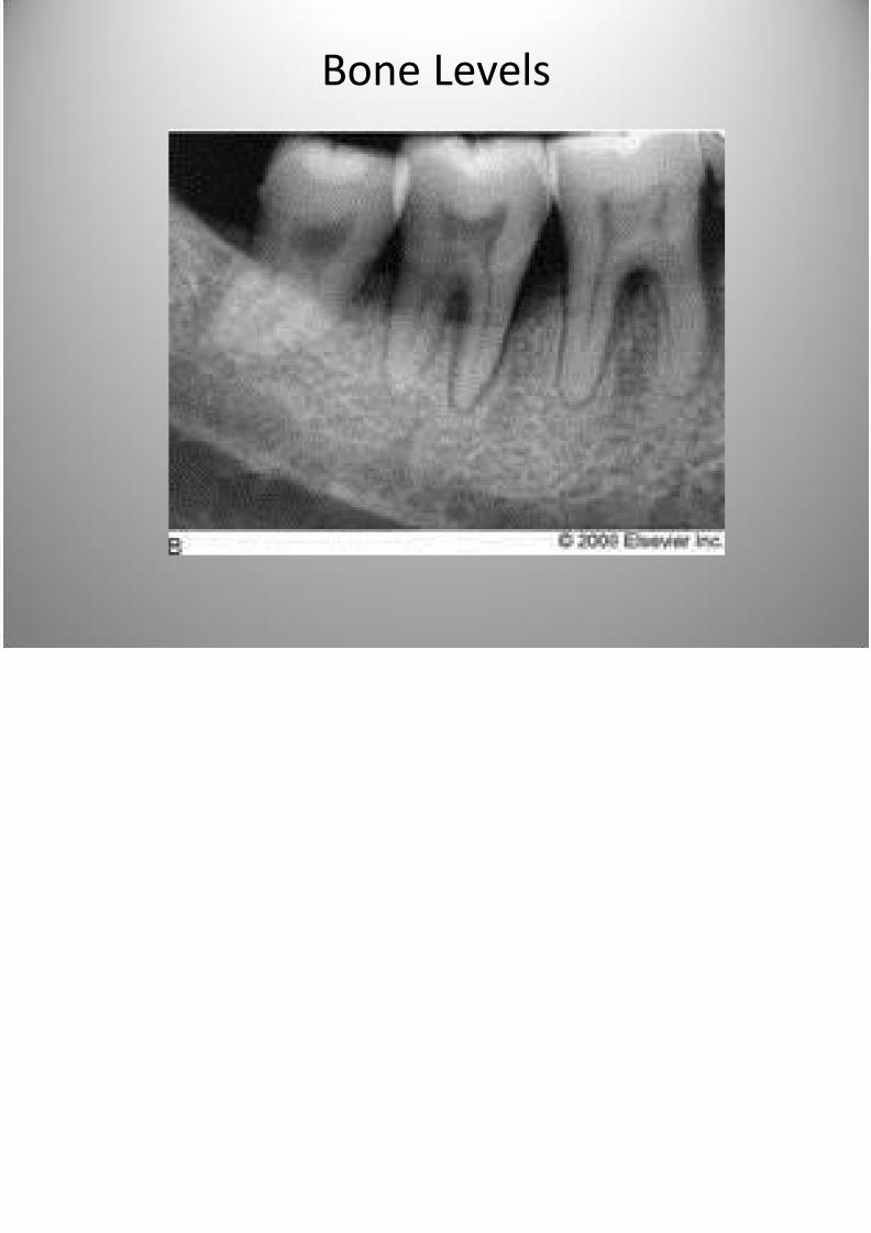
Bone Levels