Embed Size (px)
Citation preview
Radio Link
Starter Kit
Installation Manual
BARTLETT Instrument Co. 1032 Avenue H
Fort Madison, IA 52627
319-372-8366
www.bartinst.com
2
Table of Contents
Radio Link Starter Kit Manual ..................................................................... 3 System Requirements ................................................................................. 4
Quick Installation ..................................................................................... 4 Part No. System ....................................................................................... 4 Required Tools ........................................................................................ 5
Module Contents ......................................................................................... 5 Radio Disc ............................................................................................... 5 Hardware ................................................................................................. 5 Guidelines & Suggestions ........................................................................ 6
Detailed Installation Steps .......................................................................... 8 Appendix A: Compliance Statement.......................................................... 14

3
Radio Link Starter Kit Manual Thank you for purchasing the Radio Link from Bartlett Instrument Company. Figure 1 below
shows the hybrid configuration. Each configuration requires a host modules and remote module.
Figure 2 below shows the wireless configuration covered in this manual.
Figure 2: Wireless - radio to radio
Figure 1: Hybrid – radio to wired controller.
(Required for version 600 controllers)

4
This manual will guide you through the installation of the RADIO LINK. Refer to the
GH CIS manual for specific questions on the monitoring software.
As shown in Figure 1 & Figure 2, Radio Link consists of a host end and a remote end.
The host end is set up first. Next, the remote end is configured and tested using the range test
software and hardware. Once functioning, refer to the GHCIS manual for installation and use.
System Requirements 1. Windows XP with Service Pack 3 or higher
2. USB Port
3. CD Drive
Quick Installation
1. Install “USB serial driver” (CDM20830_Setup.exe) and Range Test software (Range
Test 1.0.0.8) from the provided disc. The Range Test software requires Windows XP
with Service Pack 3 or newer. For older windows, install XCTU software. When
prompted for updates, click no.
2. Connect the Host Radio (RL9600-USB) to the computer.
3. Follow any “plug and play” installation steps required. (This will happen automatically
on most computers)
4. In your computers “Start Menu”, find and run the Range Test software.
5. Select the correct COM port from the list.
6. Start the Remote Radio (RL9600-ICGH) in the range test mode. (See pages 8, 9, and 10
for more details)
7. Click “Start Auto Test.”
8. Hold down the switch on the range test board and the radios should communicate with
LED’s flashing at a regular rate on the remote radio.
9. Mount the Host Radio (RL9600-USB) in its final location.
10. Take the remote radio to the controller’s location and make sure the radios are still
communicating. (LED will flash and number of “Pass” transmissions will increase)
11. If range test passed (85% or higher), install the remote radio. To begin installing C.I.S.,
open the CD, double click Greenhouse CIS, and double click the Setup Application.
Part No. System
RL9600-HostRT-GH – RL9600-USB (Host Radio), Range Test board, and CIS
RL9600-Host-GH – RL9600-USB (Host Radio) and CIS
RL9600-ICGH – Remote In-Controller Radio
RL9600-Base-GH – RL9600-485 (Remote Base Radio), Power Supply Junction Box, and
wires
RL9600-USB – Computer USB to Radio
RL9600-485 – Radio to RS485
RLEXT – Radio Link Extension Kit
5
Required Tools
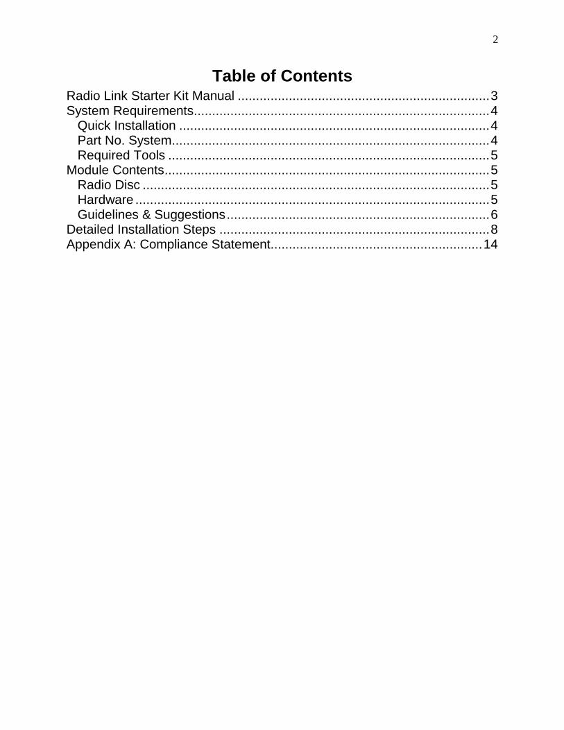
Wireless - 8mm wrench, ¼” bit
(with depth gauge) and drill, 3/16”
flat blade screwdriver
Hybrid - 3/16” flat blade
screwdriver, hammer, drill
Module Contents
Radio Disc
GH CIS – Bartlett Instrument Company’s control and monitoring program
X-CTU – Software provided by Digi International; Range test feature used during setup
to ensure maximum signal quality
USB driver
User Manuals and Guides
Hardware
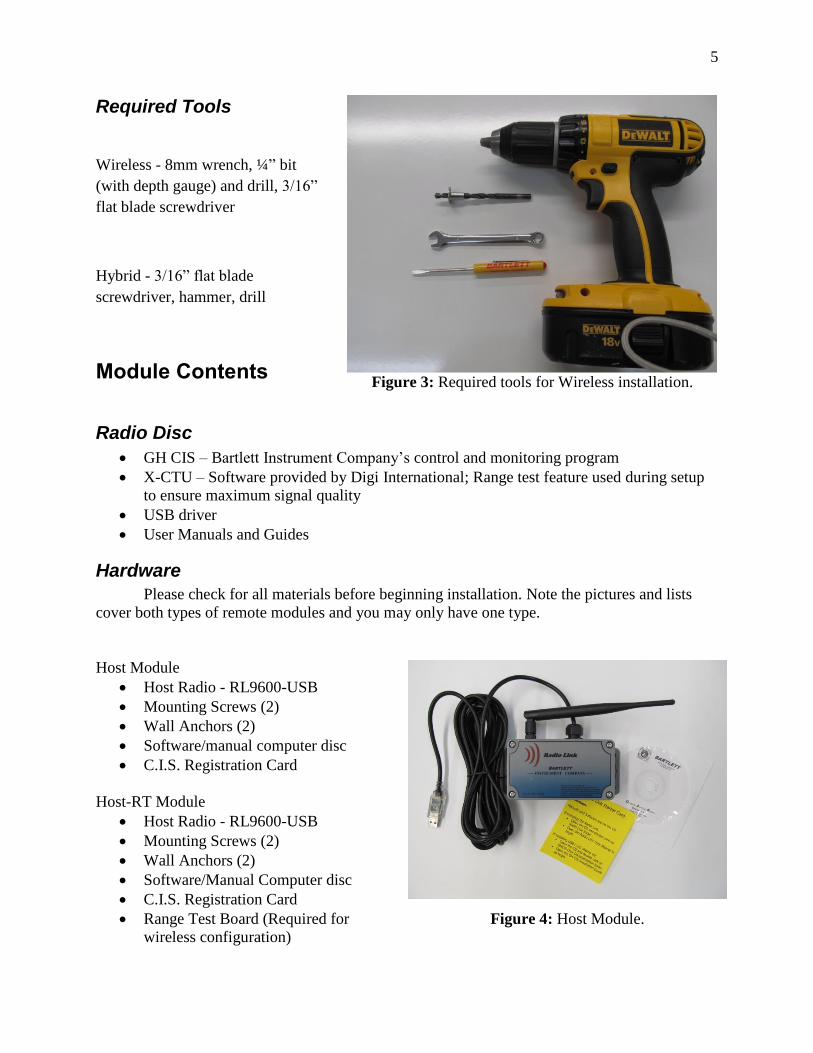
Please check for all materials before beginning installation. Note the pictures and lists
cover both types of remote modules and you may only have one type.
Host Module
Host Radio - RL9600-USB
Mounting Screws (2)
Wall Anchors (2)
Software/manual computer disc
C.I.S. Registration Card
Host-RT Module
Host Radio - RL9600-USB
Mounting Screws (2)
Wall Anchors (2)
Software/Manual Computer disc
C.I.S. Registration Card
Range Test Board (Required for
wireless configuration)
Figure 3: Required tools for Wireless installation.
Figure 4: Host Module.
6
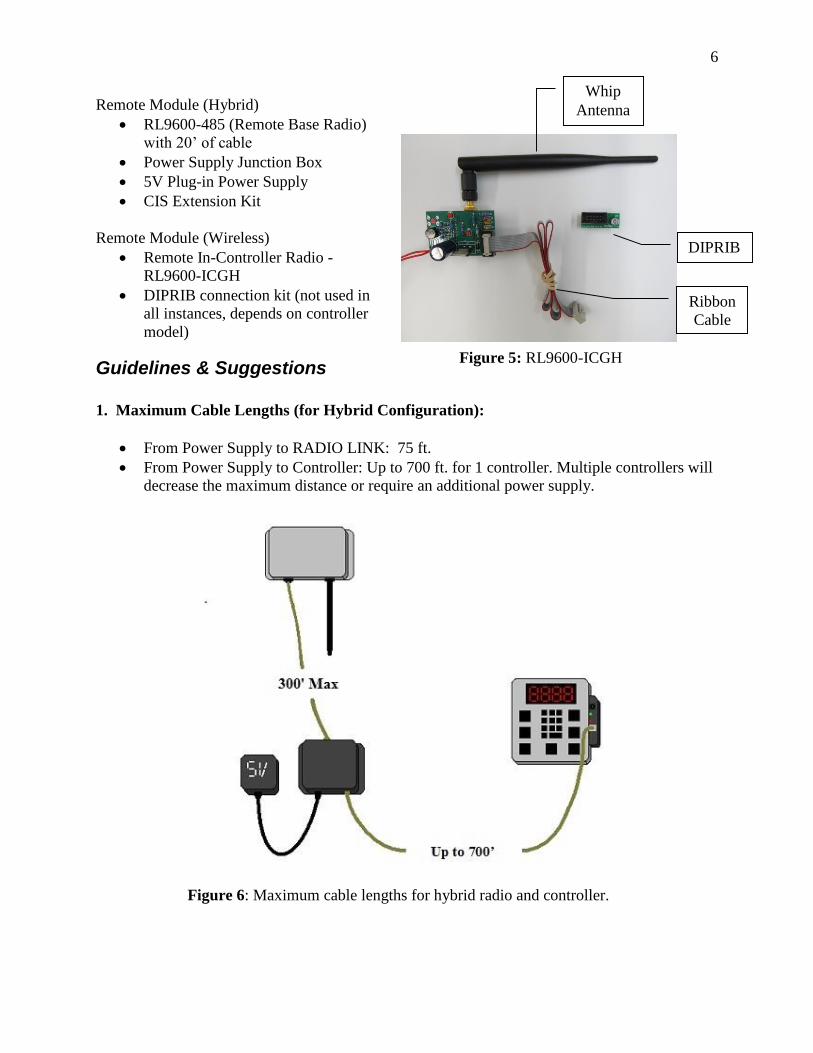
Remote Module (Hybrid)
RL9600-485 (Remote Base Radio)
with 20’ of cable
Power Supply Junction Box
5V Plug-in Power Supply
CIS Extension Kit
Remote Module (Wireless)
Remote In-Controller Radio -
RL9600-ICGH
DIPRIB connection kit (not used in
all instances, depends on controller
model)
Guidelines & Suggestions
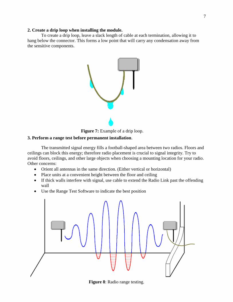
1. Maximum Cable Lengths (for Hybrid Configuration):
From Power Supply to RADIO LINK: 75 ft.
From Power Supply to Controller: Up to 700 ft. for 1 controller. Multiple controllers will
decrease the maximum distance or require an additional power supply.
Figure 6: Maximum cable lengths for hybrid radio and controller.
Figure 5: RL9600-ICGH
DIPRIB
Ribbon
Cable
Whip
Antenna
7
2. Create a drip loop when installing the module. To create a drip loop, leave a slack length of cable at each termination, allowing it to
hang below the connector. This forms a low point that will carry any condensation away from
the sensitive components.
3. Perform a range test before permanent installation.
The transmitted signal energy fills a football-shaped area between two radios. Floors and
ceilings can block this energy; therefore radio placement is crucial to signal integrity. Try to
avoid floors, ceilings, and other large objects when choosing a mounting location for your radio.
Other concerns:
Orient all antennas in the same direction. (Either vertical or horizontal)
Place units at a convenient height between the floor and ceiling
If thick walls interfere with signal, use cable to extend the Radio Link past the offending
wall
Use the Range Test Software to indicate the best position
Figure 7: Example of a drip loop.
Figure 8: Radio range testing.

8
Detailed Installation Steps 1. Install the USB serial drive (CDM20830_Setup.exe) and Range Test software (Range
Test 1.0.0.8) from the provided disc.
a. Insert the provided radio disc into your CD-ROM drive.
b. Go to your start menu and open “My Computer.”
c. Double click CD drive and open the Radio Link folder
d. Double click CDM20830_Setup.exe
i. The FTDIChip CDM Drivers screen will come up, then click “Extract”.
ii. The Device Driver Installation Wizard will come up, then click “Next”.
iii. Wait until the drivers are installed on your computer, then click “Finish”.
e. Go back to the Radio Link folder
f. Double click range test folder.
i. Double click set_up.exe
ii. Depending on your computer, you will see either a License Agreement
and click “Accept” or an Application Install screen and click “Install”.
iii. The Range Test software installation process should be complete.
2. Plug in the RL9600-USB (Host Radio) to the computer.
3. Follow any “plug and play” installation steps required. (this will happen automatically on
most computers)
4. Open your computers “Start Menu” and find the program called “Range Test”. Open and
run the Range Test software.
Figure 9: Range Test program.
9
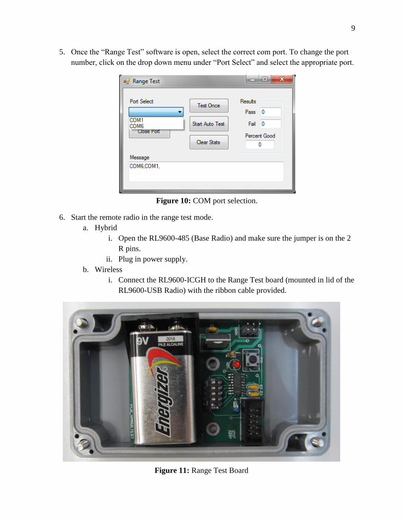
5. Once the “Range Test” software is open, select the correct com port. To change the port
number, click on the drop down menu under “Port Select” and select the appropriate port.
6. Start the remote radio in the range test mode.
a. Hybrid
i. Open the RL9600-485 (Base Radio) and make sure the jumper is on the 2
R pins.
ii. Plug in power supply.
b. Wireless
i. Connect the RL9600-ICGH to the Range Test board (mounted in lid of the
RL9600-USB Radio) with the ribbon cable provided.
Figure 10: COM port selection.
Figure 11: Range Test Board
10
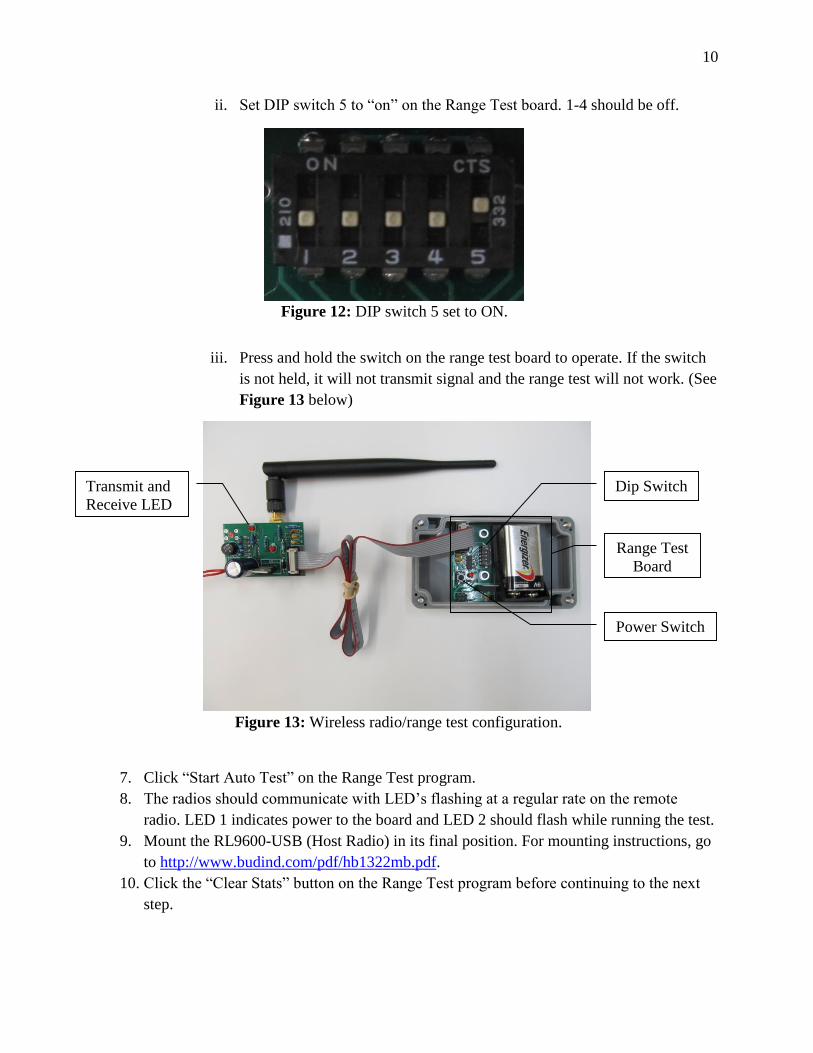
ii. Set DIP switch 5 to “on” on the Range Test board. 1-4 should be off.
iii. Press and hold the switch on the range test board to operate. If the switch
is not held, it will not transmit signal and the range test will not work. (See
Figure 13 below)
7. Click “Start Auto Test” on the Range Test program.
8. The radios should communicate with LED’s flashing at a regular rate on the remote
radio. LED 1 indicates power to the board and LED 2 should flash while running the test.
9. Mount the RL9600-USB (Host Radio) in its final position. For mounting instructions, go
to http://www.budind.com/pdf/hb1322mb.pdf.
10. Click the “Clear Stats” button on the Range Test program before continuing to the next
step.
Figure 13: Wireless radio/range test configuration.
Figure 12: DIP switch 5 set to ON.
Dip Switch
Power Switch
Transmit and
Receive LED
Range Test
Board
11
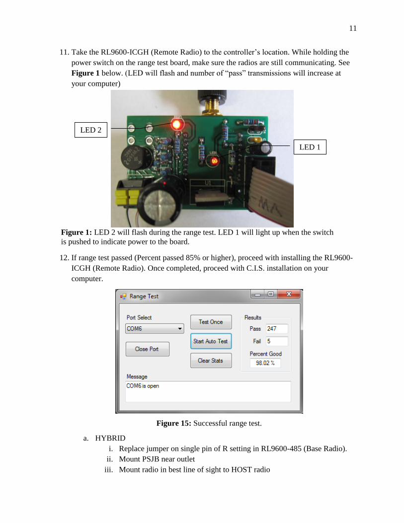
11. Take the RL9600-ICGH (Remote Radio) to the controller’s location. While holding the
power switch on the range test board, make sure the radios are still communicating. See
Figure 1 below. (LED will flash and number of “pass” transmissions will increase at
your computer)
12. If range test passed (Percent passed 85% or higher), proceed with installing the RL9600-
ICGH (Remote Radio). Once completed, proceed with C.I.S. installation on your
computer.
a. HYBRID
i. Replace jumper on single pin of R setting in RL9600-485 (Base Radio).
ii. Mount PSJB near outlet
iii. Mount radio in best line of sight to HOST radio
Figure 1: LED 2 will flash during the range test. LED 1 will light up when the switch
is pushed to indicate power to the board.
Figure 15: Successful range test.
LED 2
LED 1
12
iv. Mount CIS extension kit in controller. Refer to CIS Installation Manual.
v. Connect controller to PSJB.
1. With modular cables
2. With cat5 wire
b. WIRELESS
i. Disconnect RL9600-ICGH (Remote Radio) from range test board.
ii. Remove power from the controller.
iii. Remove controller lid from the controller.
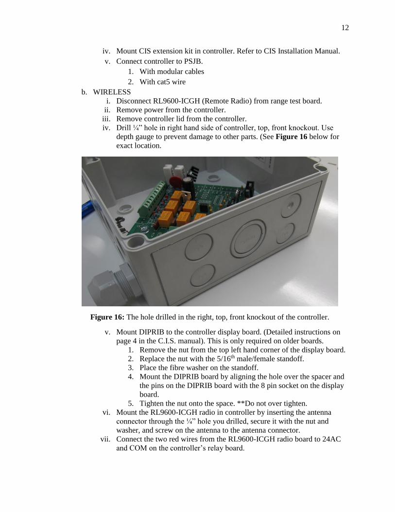
iv. Drill ¼” hole in right hand side of controller, top, front knockout. Use
depth gauge to prevent damage to other parts. (See Figure 16 below for
exact location.
v. Mount DIPRIB to the controller display board. (Detailed instructions on
page 4 in the C.I.S. manual). This is only required on older boards.
1. Remove the nut from the top left hand corner of the display board.
2. Replace the nut with the 5/16th male/female standoff.
3. Place the fibre washer on the standoff.
4. Mount the DIPRIB board by aligning the hole over the spacer and
the pins on the DIPRIB board with the 8 pin socket on the display
board.
5. Tighten the nut onto the space. **Do not over tighten.
vi. Mount the RL9600-ICGH radio in controller by inserting the antenna
connector through the ¼” hole you drilled, secure it with the nut and
washer, and screw on the antenna to the antenna connector.
vii. Connect the two red wires from the RL9600-ICGH radio board to 24AC
and COM on the controller’s relay board.
Figure 16: The hole drilled in the right, top, front knockout of the controller.

13
viii. Attach the ribbon cable provided from the Radio board to the DIP RIB
board you installed on controller display board. (See Figure 17 on the
next page for the complete hook up.)
ix. Replace lid and restore power.
x. Remember, you will need to change the controller’s ID if this is not the
first controller on the network.
Figure 17: All power connections hooked up.
DIP RIB
Radio Ribbon Cable
RL9600
-ICGH
Red Power
Wires From
Radio
14
Appendix A: Compliance Statement
Compliance Statement (Part 15.19)
This device complies with Part 15 of the FCC Rules.
Operation is subject to the following two conditions:
1. This device may not cause harmful interference, and
2. This device must accept any interference received, including interference that may cause
undesired operation
Warning (Part 15.21)
Changes or modifications not expressly approved by the party responsible for compliance could
void the user’s authority to operate the equipment.
RF Exposure (OET Bulletin 65)
To comply with FCC RF exposure requirements for mobile transmitting devices, this transmitter
should only be used or installed at locations where there is at least 20cm separation distance
between the antenna and all persons.
Information to the User – Part 15.105(b)
This equipment has been tested and found to comply with the limits for a Class B digital device,
pursuant to part 15 of the FCC Rules. These limits are designed to provide reasonable protection
against harmful interference in a residential installation. This equipment generates, uses, and can
radiate radio frequency energy, and, if not installed and used in accordance with the instructions,
may cause harmful interference to radio communications. However, there is no guarantee that
interference will not occur in a particular installation. If this equipment does cause harmful
interference to radio or television reception, which can be determined by turning the equipment
off and on, the user is encouraged to try to correct the interference by one or more of the
following measures:
Reorient or relocate the receiving antenna
Increase the separation between the equipment and receiver
Connect the equipment into an outlet on a circuit different from that to which the receiver
is connected
Consult the dealer or an experienced radio/TV technician for help


![FM Microwave Radio Link - Elber radio TV broadcast …UserManuals~NBFM_[EN].pdfFM Microwave Radio Link Transmitter T_NBFM-01 ... microwave radio link. It is able to transfer, over](https://img.pdfslide.us/doc/110x75/5ab9bcd47f8b9aa6018e34cf/fm-microwave-radio-link-elber-radio-tv-broadcast-usermanualsnbfmenpdffm.jpg)