Embed Size (px)
Citation preview
RADIO ESTABLISHED 1917
DESIGN, RESEARCH
PRODUCTION, OPERATION
www.americanradiohistory.com
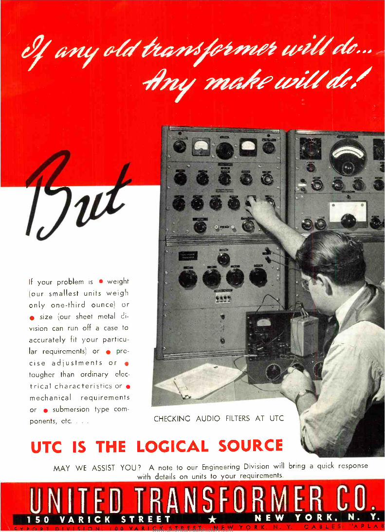
If your problem is weight
(our smallest units weigh
only one -third ounce) or
size (our sheet metal di-
vision can run off a case to
accurately fit your particu-
lar requirements) or pre-
cise adjustments or tougher than ordinary elec-
trical characteristics or
mechanical requirements
or submersion type com-
ponents, etc. . . . CHECKING AUDIO FILTERS AT UTC
UTC IS THE LOGICAL SOURCE MAY WE ASSIST YOU? A note to our Engineering Division will bring a quick response
with details on units to your requirements.
UNITED TRANSFORMER CO. 1 S0 VARICK STREET * NEW YORK, N. Y.
www.americanradiohistory.com
FOR OUTSTANDING ACHIEVEMENT
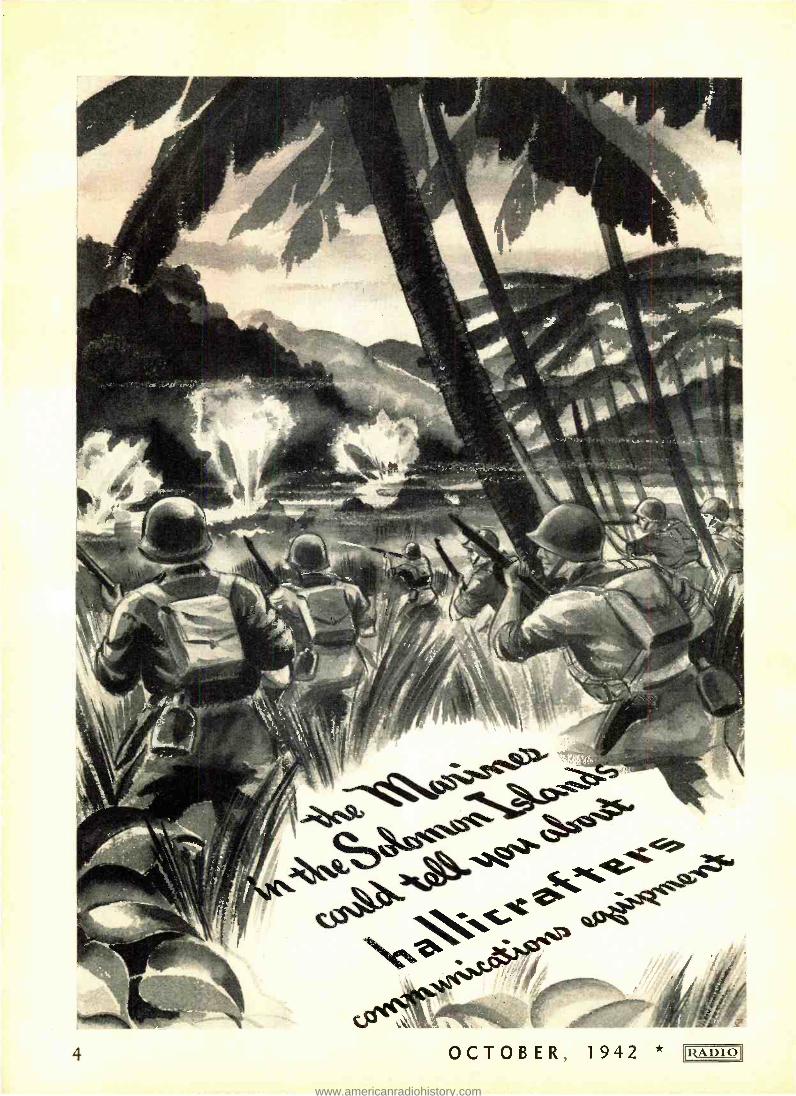
... the °'E" emblem is t ute to the prowess of Americ the field of shortwave communications. rations. Ilallicrafters workers by [heir unswerv- ing purpose to produce a product that is better, and to exceed their quotas in order that production schedules can be maintained, have been awarded this honor.
The accumulative electronic ex- perience gained by Ilallicrafters employes will be a dominant factor in future peace time production of advanced designs in shortwave communications receivers.
RADIO * OCTOBER, 1942 3
www.americanradiohistory.com
Editor
M. L. MUHLEMAN
Business Staff Lee Robinson, Publisher
and President
S. R. Cowan, Business Manager
and Treasurer
M. L. Muhleman, Vice President and Editor
R. Alan, Circulation Manager
CORRESPONDENCE and ORDERS should be sent only to our New York office. MANUSCRIPTS, if unsolicited and un- usable, will not be returned unless accom- panied by a stamped, self -addressed en velope.
EXECUTIVE, editorial, and advertising offices of Radio Magazines, Inc., are lo- cated at 132 West 43rd Street, New York, N. Y., to which address all correspondence, advertising copy and cuts should be directed.
SUBSCRIPTION RATES (in U. S. funds): Two years, $5.00, or $3.00 yearly in U.S.A. To Canada and all foreign coun- tries, $4.00 yearly. Twelve issues yearly; back issues are not included in subscriptions.
NOTE: Because of wartime censorship re- strictions, we must reserve the right to withhold from foreign subscribers any issue the regular domestic edition of which is not approved by the authorities for export with- out changes. In such cases subscriptions will be extended so that each subscriber will eventually receive the number of issues to which he is entitled.
f IF YOU MOVE, notify us in advance; we cannot replace copies sent to your old ad- dress. Notice must be received by the 20th of the month preceding the cover date of first issue to go to the new address.
Published by RADIO MAGAZINES, INC.
OCTOBER 1942 No. 273
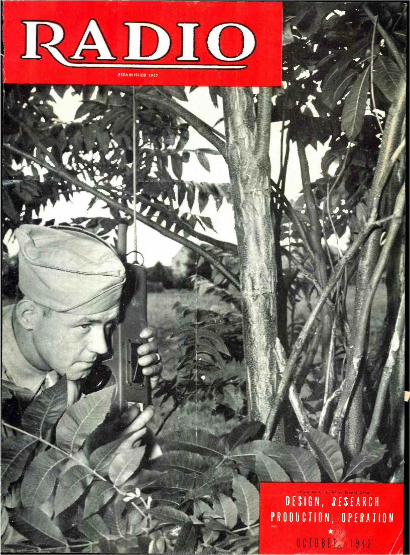
Table of Contents COVER
Staff Sergeant Thomas W. Gloystein is shown in the field with a portable "Handy- Talkie" transceiver. He was formerly a fireman from Cincinnati and
is now an instructor of radio communication at Fort Benning, Ga.
ARTICLES
U.H.F. Antennas -C. R. Stoll l)
Army -Navy Preferred List of Vacuum Tubes Il Theory and Limitations of Universal A.C. Bridge- Lieutenant- Comniand-
er J. H. Ellison 12
Graphite Shielding -B. H. Porter 14
Thirteen Ways to Prolong Tube Life 15
Ground System at KMPC 16
Q. & A. Study Guide 18
Broadcast Station Maintenance and Operation, Part II -C. H. Wesser 19
Notes on Receiver Design -David Eby, Jr 22
Radio Design Worksheet : No. 6- Thevenin's Theorem 23
Radio Bibliography: 6- Filters, Sound, Loudspeakers -F. X. Retteumeyer 26
MISCELLANEOUS
Editorial 7
New Products 24
New RCA Laboratories Dedicated 36
News 44
Advertising Index 50
RADIO (title registered U.S. Pat. Off.) is published monthly at 34 N. Crystal Street, East Stroudsburg, Pa., by Radio Magazines, Inc., Executive and Editorial Offices at 132 West 43d Street, New York, N. Y. Subscription rates -United States and Possessions, $3.00 for 1 year, $5.00 for 2 years; else- where $4.00 per year. Single copies 35c. Printed in U.S.A. All rights reserved, entire contents Copyright 1942 by Radio Magazines, Inc. Application Pending for transfer of Second Class Entry from Santa Barbara, Calif., to East Stroudsburg, Pa.
__ * OCTOBER, 1942 5
www.americanradiohistory.com
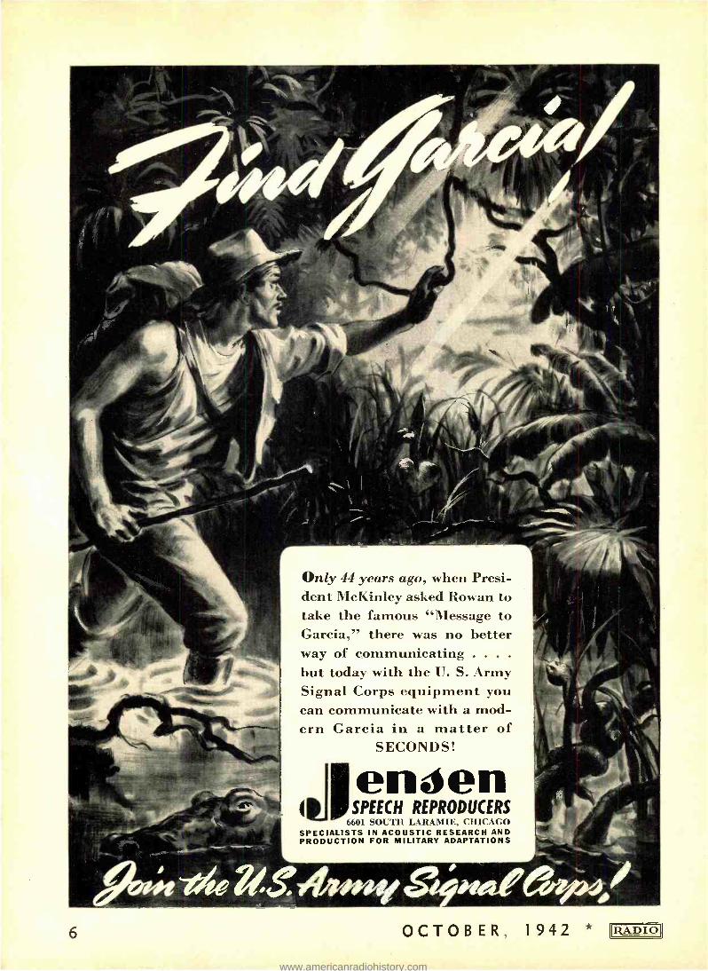
Only 44 years ago, when Presi- dent McKinley asked Rowan to take the famous "Message to Garcia," there was no better way of communicating . . . .
but today with the U. S. Army Signal Corps equipment you can communicate with a mod- ern Garcia in a matter of
SECONDS!
L
4
engen SPEECH REPRODUCERS
6601 SOUTH LARAMIE, CHICAGO SPECIALISTS IN ACOUSTIC RESEARCH AND PRODUCTION FOR MILITARY ADAPTATIONS
6 OCTOBER, 1942 * IRADIOI
www.americanradiohistory.com
EDITORIAL
JEEP FREQUENCIES
* We have received a very engaging letter from Mr. G. Parr, editor of the English journal Electronic Engineering, with regard to our editorial on ultra- high frequency terminology, in the May issue.
Mr. Parr assures us that the English are not using the abbreviation U.H.F.I. (Ultra High Frequency Indeed) as we intimated, which leaves us holding the bag and chalks up one for Electronics, who attributed the origin to a group of American college professors.
But -since when have Americans been using the word "indeed" as an expression of emphasis? It's too typically British.
Or, is it an example of lend -lease in reverse? If that is the case, then we offer to the radio engineers of Great Britain a good Yankee counterpart -Jeep Frequencies!
Mr. Parr has called our attention to a suggestion offered by Dr. Fleming- Williams in a letter to the editor of The Wireless Engineer. He proposes that the whole frequency spectrum be divided up into a number of bands defined in the following manner.
If a frequency is expressed in cycles per second, it will lie in a band whose number is equal to the logarithm of the frequency to base 10. The band num- ber is therefore given by expressing the frequency as a number between 1 and 10 multiplied by a power of 10, and using that power as the band number.
For example 50 megacycles is 5 x 10' cycles, and the band number is 7.
It is pointed out that the present terminology does not correspond to the band numbers exactly, but this should not bring up difficulties. And the method can be extended into the light waves, which would be associated with band 14.
IMAGINEERING * Said the Aluminum Company of America in a re- cent advertisement "Dream a Dream Every Day. Re- member that the kind of peace we all want depends on how many jobs we think up for the boys coming back. New jobs come out of new things to make. Let your imagination soar ; engineer it down to earth ;
then file the plans away, ready for the day when. That's Imagineering!"
The promise this good advice holds for now and the future is best expressed by the slogan in the same advertisement -So Much So Soon.
RADIO- NEUROSIS * It is reported from Washington that the Office of War Information is about to apply inverse feedback to the Axis Powers' war of nerves. The plan has the approval of the War Communications Board ; and
RADIO * OCTOBER, 1942
OWI contemplates the development and operation of 36 short -wave transmitters for the purpose of reach- ing audiences in enemy territory.
A radio barrage is difficult to dodge in localities where a curiosity born of fear has emerged, and no power can completely remove the desire to listen. The enemy and the subjugated alike will bend an ear to what the United States has to say.
Facts and figures will strike deep ; but we rather hope that our strategists of the air turn to the tech- nique of the dentist, who is never so terrifying as at the moment he so untruthfully says, Now, this isn't going to hurt.
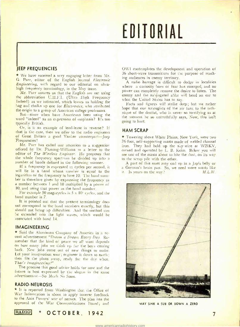
HAM SCRAP
* Towering above White Plains, New York, were two 76 -foot, self- supporting masts made of welded channel iron. They had held up the sky -wire at W2IKV, owned and operated by L. B. Keim. Below you will see one of the masts about to bite the dust, on its way to the scrap pile with the other.
A part of this mast may end up in a Jap's belly or a German's brain pan. So, we need more masts like it. Is yours on the way?
MAY SINK A SUB OR DOWN A ZERO
7
www.americanradiohistory.com
:I
Centralab MIDGET
RADIOHMS Servicemen recognize the "plus-performance" that these sturdy controls give on every replacement job...Old Man Centralab's good advice to "ALWAYS SPECIFY CENTRALAB"
was never more timely than now . . . when it is so important to keep the "radio ears" of
the nation properly tuned to the events of
these critical moments in our history . . . For smooth, silent, sure attenuation . . . specify
CENTRALAB MIDGET RADIOHMS
CENTRALAB: DIV. OF GLOBE-UNION INC.
MILWAUKEE, WISCONSIN, U.S. A.
ilH
OCTOBER, 1942 * RADIO
www.americanradiohistory.com
U. H. F. ANTENNAS
* Someone once said that antennas, like women, may be had in so many shapes and sizes that choosing becomes difficult.
Generally speaking, however, any one type will be an effective radiator if properly excited.
The purpose of this text, therefore, is to explain the operation and adjust- ment of various antennas and feeder systems. Thus, a prospective user will be able to pick, more satisfactorily, the system most readily applied to the con- ditions at hand.
There are basically, two different methods of antenna operation; these are Marconi and Hertz. The latter is used almost exclusively on u.h.f. and consists of a half -wave radiator, or some multiple thereof, operated in free space. The Marconi on the other hand is always a quarter wave long or some odd multiple of this. It is worked against ground and with this connec- tion an image, similar to the antenna, is set up in the earth. Both systems have desirable qualities depending on requirements.
Zepp Types
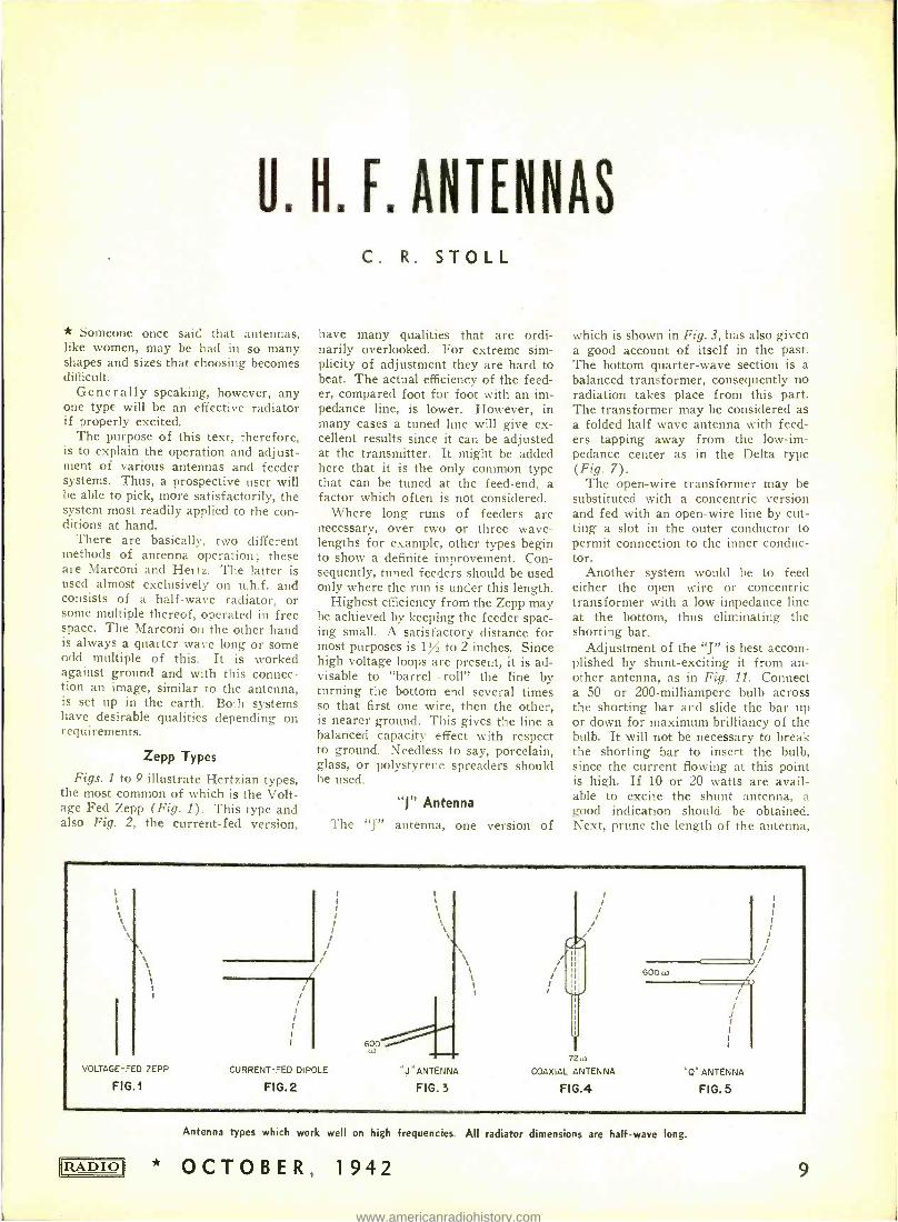
Figs. 1 to 9 illustrate Hertzian types, the most common of which is the Volt- age Fed Zepp (Fig. 1). This type and also Fig. 2, the current -fed version,
C. R. STOLL
have many qualities that are ordi- narily overlooked. For extreme sim- plicity of adjustment they are hard to beat. The actual efficiency of the feed- er, compared foot for foot with an im- pedance line, is lower. However, in many cases a tuned line will give ex- cellent results since it can be adjusted at the transmitter. It might be added here that it is the only common type that can be tuned at the feed -end, a factor which often is not considered.
Where long runs of feeders are necessary, over two or three wave- lengths for example, other types begin to show a definite improvement. Con- sequently, tuned feeders should be used only where the run is under this length.
Highest efficiency from the Zepp may be achieved by keeping the feeder spac- ing small. A satisfactory distance for most purposes is 1Y, to 2 inches. Since high voltage loops are present, it is ad- visable to "barrel - roll" the line by turning the bottom end several times so that first one wire, then the other, is nearer ground. This gives the line a balanced capacity effect with respect to ground. Needless to say, porcelain, glass, or polystyrene spreaders should he used.
"J" Antenna The "J" antenna, one version of
which is shown in Fig. 3, has also given a good account of itself in the past. The bottom quarter -wave section is a balanced transformer, consequently no radiation takes place from this part. The transformer may be considered as a folded half -wave antenna with feed- ers tapping away from the low -im- pedance center as in the Delta type (Fig. 7).
The open -wire transformer may be substituted with a concentric version and fed with an open -wire line by cut- ting a slot in the outer conductor to permit connection to the inner conduc- tor.
Another system would be to feed either the open wire or concentric transformer with a low- impedance line at the bottom, thus eliminating the shorting bar.
Adjustment of the "J" is best accom- plished by shunt -exciting it from an- other antenna, as in Fig. 11. Connect a 50- or 200 -milliampere bulb across the shorting bar and slide the bar up or down for maximum brilliancy of the bulb. It will not be necessary to break the shorting bar to insert the bulb, since the current flowing at this point is high. If 10 or 20 watts are avail- able to excite the shunt antenna, a good indication should be obtained. Next, prune the length of the antenna,
VOLTAGE -FED ZEPP
FIG.1
/ /
600
CURRENT-FED DIPOLE
FIG.2 "J" ANTENNA
FIG.3
f.
72
COAXIAL ANTENNA
FIG.4
600)
/ /
/ 1
/ I
I
"0" ANTENNA
FIG.5
RADIO
Antenna types which work well on high frequencies. All radiator dimensions are half -wave long.
* OCTOBER, 1942 9
www.americanradiohistory.com
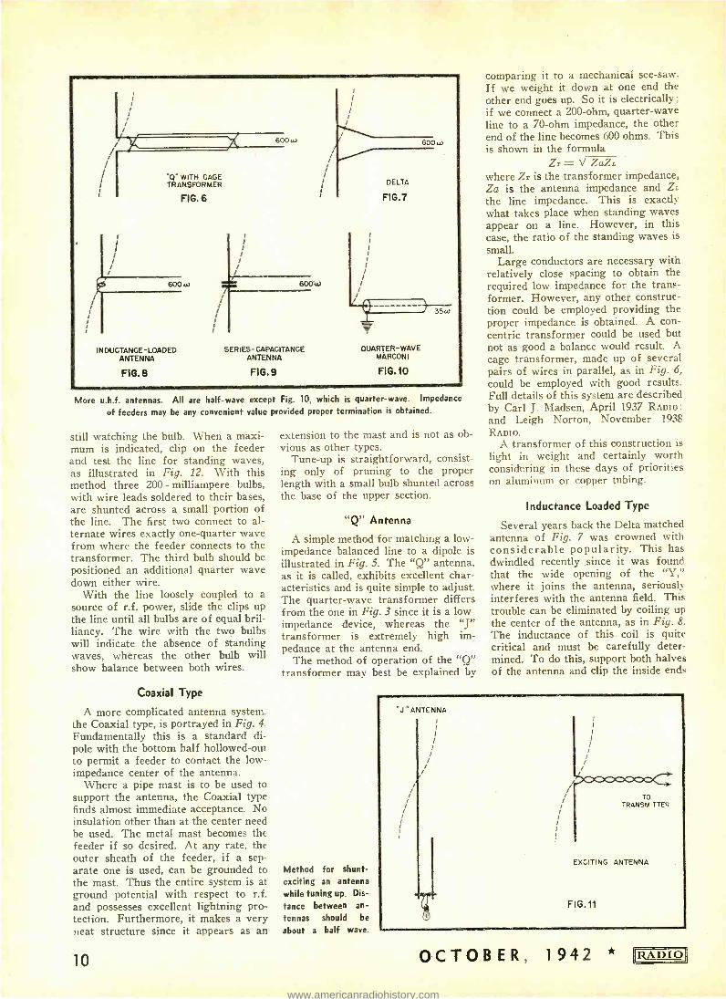
*Q. WITH CAGE TRANSFORMER
FIG. 6
600 w
INDUCTANCE - LOADED ANTENNA
600 w
600w
SERIES -CAPACITANCE ANTENNA
FIG.8 FIG.9
600 w
DELTA
FIG.7
V OUARTER -WAVE
MARCONI
FIG.10
36w
More u.h.f. antennas. All are half -wave except Fig. 10, which is quarter -wave. Impedance
of feeders may be any convenient value provided proper termination is obtained.
still watching the bulb. When a maxi- mum is indicated, clip on the feeder and test the line for standing waves, as illustrated in Fig. 12. With this method three 200 - milliampere bulbs, with wire leads soldered to their bases, are shunted across a small portion of the line. The first two connect to al- ternate wires exactly one -quarter wave from where the feeder connects to the transformer. The third bulb should be positioned an additional quarter wave down either wire.
With the line loosely coupled to a source of r.f. power, slide the clips up the line until all bulbs are of equal bril- liancy. The wire with the two bulbs will indicate the absence of standing waves, whereas the other bulb will show balance between both wires.
Coaxial Type
A more complicated antenna system, the Coaxial type, is portrayed in Fig. 4.
Fundamentally this is a standard di- pole with the bottom half hollowed -out to permit a feeder to contact the low - impedance center of the antenna.
Where a pipe mast is to be used to support the antenna, the Coaxial type finds almost immediate acceptance. No insulation other than at the center need be used. The metal mast becomes the feeder if so desired. At any rate, the outer sheath of the feeder, if a sep- arate one is used, can be grounded to the mast. Thus the entire system is at ground potential with respect to r.f. and possesses excellent lightning pro- tection. Furthermore, it makes a very neat structure since it appears as an
10
extension to the mast and is not as ob- vious as other types.
Tune -up is straightforward, consist- ing only of pruning to the proper length with a small bulb shunted across the base of the upper section.
"Q" Antenna
A simple method for matching a low - impedance balanced line to a dipole is illustrated in Fig. 5. The "Q" antenna, as it is called, exhibits excellent char- acteristics and is quite simple to adjust. The quarter -wave transformer differs from the one in Fig. 3 since it is a low - impedance device, whereas the "J" transformer is extremely high im- pedance at the antenna end.
The method of operation of the "Q" transformer may best be explained by
Method for shunt -
exciting an antenna while tuning up. Dis-
tance between an-
tennas should be
about a half wave .
comparing it to a mechanical see -saw. If we weight it down at one end the other end goes up. So it is electrically ;
if we connect a 200 -ohm, quarter -wave line to a 70 -ohm impedance, the other end of the line becomes 600 ohms. This is shown in the formula
Zr = d ZaZi where Zr is the transformer impedance, Za is the antenna impedance and ZL
the line impedance. This is exactly what takes place when standing waves appear on a line. However, in this case, the ratio of the standing waves is small.
Large conductors are necessary with relatively close spacing to obtain the required low impedance for the trans- former. However, any other construc- tion could be employed providing the proper impedance is obtained. A con- centric transformer could be used but not as good a balance would result. A cage transformer, made up of several pairs of wires in parallel, as in Fig. 6,
could be employed with good results. Full details of this system are described by Carl J. Madsen, April 1937 RADIO: and Leigh Norton, November 1938
RADIO. A transformer of this construction is
light in weight and certainly worth considering in these days of priorities on aluminum or copper tubing.
Inductance Loaded Type
Several years back the Delta matched antenna of Fig. 7 was crowned with considerable popularity. This has dwindled recently since it was found that the wide opening of the "Y," where it joins the antenna, seriously interferes with the antenna field. This trouble can be eliminated by coiling up the center of the antenna, as in Fig. 8.
The inductance of this, coil is quite critical and must be carefully deter- mined. To do this, support both halves of the antenna and clip the inside ends
OCTOBER, 1942 * RADIO
www.americanradiohistory.com
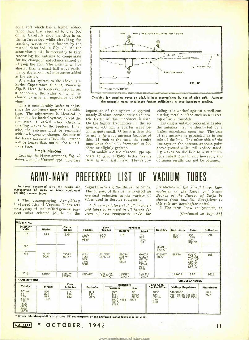
on a coil which has a higher induc- tance than that required to give 600 ohms. Carefully slide the clips in on the inductance while checking for ., tanding waves on the feeders by the method described in Fig. 12. At the same time it will be necessary to keep resonating the antenna to compensate for the change in inductance caused by varying the coil. The antenna will be shorter than a usual half -wave radia- tor by the amount of inductance added at the center.
A similar system to the above is a Series Capacitance antenna, shown in Fig. 9. Here the feeders connect across a condenser, the value of which is chosen to give an impedance of 600 ohms.
This is considerably easier to adjust since the condenser may be a variable type. The adjustment is identical to the inductive loaded system, except the condenser is varied while checking standing waves on the feeders. Like- wise, the antenna must be resonated with each capacity change. Because of the series capacity effect, the antenna will be longer than normal for a half - wave type.
Simple Marconi Leaving the Hertz antennas, Fig. 10
shows a simple Marconi type. The base
%4),
I( LINE TERMINATION
E- 2 OR 3 INCH SPACING BETWEEN LEADS
"----------- a
->1
I/2
STANDING WAVES
TO TRANSMITTER
FIG.12
Checking for standing waves on u.h.f. is best accomplished by use of pilot bulb. Average thermocouple meter unbalances feeders sufficiently to give inaccurate reading.
impedance of this system is approxi- mately 35 ohms, consequently a concen- tric feeder of this impedance is used. On the higher frequencies, in the re- gion of 400 mc., a quarter wave be- comes quite small. Often it is desirable to use a 3/4 -wave antenna because of this. If such is the case, the feeder impedance should be increased to 100 ohms or slightly greater.
For mobile use the Marconi type ap- pears to give slightly better results than the usual half wave. This is pro-
viding it is worked against a well -con- ducting metal surface such as a turret - top of an automobile.
Lacking a suitable concentric feeder, the antenna may be shunt - fed by a higher impedance open line. The base of the antenna is grounded as is one side of the line. The other side of the line taps on the antenna at some point above ground which will reduce stand- ing waves on the line to a minimum. This unbalances the line however, and optimum results can not be obtained.
ARMY -NAVY PREFERRED LIST Of VACUUM TUBES To those concerned with the design and
manufacture of Army or Navy equipment utilizing vacuum tubes:
1. The accompanying Army -Navy Preferred List of Vacuum Tubes sets up a group of unclassified general pur- pose tubes selected jointly by the
Signal Corps and the Bureau of Ships. The purpose of this list is to effect an eventual reduction in the variety of tubes used in Service equipment.
2. It is mandatory that all unclassi- fied tubes to be used in all future de- signs of new equipments under the
jurisdiction of the Signal Corps Lab- oratories or the Radio and Sound Branch of the Bureau of Ships be chosen from this list. Exceptions to this rule are hereinafter noted.
3. The term "new equipments ", as
[Continued on page 381
RECEIVING
Filament Volts Diodes
Diode Triodes Triodes
Twin Triodes
Pentodes Rectifiers Converters Power Indicators Remote Sharp
1.4 1A3 1LH4 1G4GT 957 958A
1291 3A5
TT4 155
959
1L4
1LC6 1R5
3A4 12299
3Q5GT
991
5.0 5U4G 5Y3 -GT
6.3 6H6* 9004
65Q7° 6SR7°
615° 1201 955 7193 9002
6SL7GT 6SN7GT
55G7ß 6SK7* 956 9003
6ÁC7# 6AG7* 6SH7* 6SJ7° 717 -A 954 9001
6X5 -GT 1005
6SA7° 6L6 -G 6V6 -GT 6N7 -GT 6B4 -G 6G6 -G 6Y6 -G
6E5
12.6 12H6* 12SQ7* 12SR7*
1215 -GT 12SL7 -GT 12SN7 -GT
12SG7° 125K7ß
12SH7* 12S17ß
12SA7* 12A6 1629
TRANSMITTING MISCELLANEOUS
Triodes Tetrodes Twin
Tetrodes Pentodes Rectifiers Grid Cont.
Gas Rectifiers Voltage Regulators Phototuben Vacuum Gas 801 -A 811 826
8386 838
A
8005 8025 304TH
807 813 814 1625
815 829 832
803 837 2E22
2X2 836 1616 8020 (451) 705A 371A
83 866A 872A
4825
2050 884 394 -A C1B C5B
VR -90 -30 VR- 105 -30 (38205) VR- 150 -30 138250)
918 927
s Where Interchangeability is assured CT counterparts of the preferred metal tubes may be used.
RADIO * OCTOBER, 1942 11
www.americanradiohistory.com
THEORY AND LIMITATIONS OF
UNIVERSAL A. C. BRIDGE
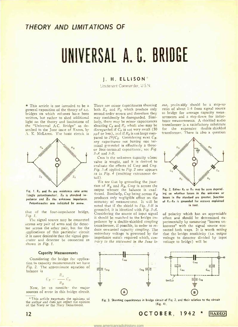
* This article is not intended to be a general exposition of the theory of a.c. bridges on which volumes have been written, but rather to shed additional light on the theory and limitations of the "Universal A.C. Bridge" as de- scribed in the June issue of RADIO, by A. K. McLaren. The basic circuit is
Fig. 1. RA and Rs are resistance ratio arms
(single potentiometer). Zs is standard im-
pedance and Zx the unknown impedance. Potentiometer arm indicated by arrow.
that of the four -impedance bridge, Fig. 1.
The signal source may be connected across any pair of arms and the detec- tor across the other pair, but for the applications of this particular circuit it is more desirable that the signal gen- erator and detector be connected as shown in Fig. 1.
Capacity Measurements
Considering the bridge for applica- tion to capacity measurements we have Fig. 2. The approximate equation of balance is
C% =
Now, let us sources of error
RA Cs.
RB consider the in this bridge
major circuit.
* This article expresses the opinions of the author and does not reflect the opinion of the Navy or the Navy Department.
12
J. H. ELLISON Lieutenant Commander, U.S.N.
There are minor capacitances shunting both RA and RB which produce only second -order errors and therefore they may confidently be disregarded. Simi- larly, there may be minor capacitances shunting Cs and Rs which also may be disregarded if Cs is not very small (50 µµf or less), and if Rs is not large com- pared to 27 fCs. Considering next Cg, any capacitance not having one ter- minal grounded is effectively a three - or four -terminal capacitance; see Fig. 3 -A and 3 -B.
Ctin is the unknown capacity whose value is sought, and it is desired to evaluate the effects of Cmg and Cng. Fig. 3 -A applied to Fig. 2 now appears as in Fig. 4 (omitting extraneous de- tail).
We see that by grounding the junc- tion of RA and RB, Cmg is across the output whence the balance is unaf- fected. Similarly, Cng being across RB produces only negligible effect on the accuracy of measurement. It will be noted that if the shield in Fig. 3 -B is grounded, it is identical with Fig. 3 -A. Considering the source of input signal it should be matched to the bridge im- pedance by a double- shielded coupling transformer, if possible, in order to re= duce unwanted capacity coupling. The secondary voltage is governed by the impedance match required which, con- trary to the statement in the June is-
I Cmn
O
Cng c=
sue, preferably should be a step -up ratio of about 1:4 from signal source to bridge for average capacity meas- urements and a step -down for induc- tance measurements. A shielded audio transformer is a satisfactory substitute for the expensive double- shielded transformer. There is also a question
Fig. 2. Either R,, or Rx may be zero depend-
ing on whether losses in the unknown or
losses in the standard are greater. Junction
of R, -RR is grounded for reasons explained
in text.
of polarity which has an appreciable effect and should be determined ex- perimentally by measuring "known un- knowns" with the signal source con- nected both ways. It is worth noting that the bridge sensitivity (i.e. output voltage to detector divided by input voltage to bridge) will be
r 1
O l T
!!.
1 1 T
L SHIELD
Fig. 3. Shunting capacitances in bridge circuit of Fig. 2, and their relation to the circuit (Fig. 4).
OCTOBER, 1942 *
o
11RADIO11
www.americanradiohistory.com
CL Cny c
Cmg
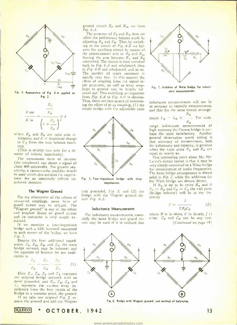
Fig. 4. Appearance of Fig. 3 -A applied to Fig. 2.
RA
E out RB
E in Xd
RB
where RA and RB are ratio arm re- sistances, and d = fractional change in Cx from the true balance condi- tion. (This is strictly true only for a de-
tector of infinite impedance). The commonest form of detector
(the telephone) can detect a signal of about 400 microvolts. For greater sen- sitivity, a vacuum -tube amplifier should be used which also satisfies the require- ment fior an essentially infinite im- pedance detector.
The Wagner Ground
For the elimination of the effects of unwanted couplings, some form of guard circuit may be utilized. The "Wagner ground" is one of the oldest and simplest forms of guard circuit and its operation is very simply ex- plained.
If we consider a four -impedance bridge with a fifth terminal connected to each corner of the bridge, we have Fig. 5.
Despite the four additional imped- ances, Zc, ZD, ZB, and Zr,., the main bridge network may be balanced and the equation of balance for our appli- cation is
ZA Ze Z,y
ZB ZD ZY
Here ZA, ZB, Zs and Zx represent our original bridge network with no point grounded, and Zr, ZD, ZB and Zle represent the various stray im- pedances from the four points of the bridge to a cothmon point, the ground.
If we take our original Fig. 2, re- move the ground and acid the Wagner
RADIO
ground circuit Ro and RD, we have Fig. 6 -A.
The presence of Re and RD does not affect the preliminary balance made by adjusting RA and RB. Then by switch- ing to the circuit of Fig. 6 -B we bal- ance the auxiliary circuit by means of the potentiometer arm on Re and RD, leaving the arm between RA and RB untouched. The circuit is then switched back to Fig. 6 -A and rebalanced, then to Fig. 6 -B and rebalanced, and so on. The number of trials necessary is usually very few. In this manner the effect of coupling from the signal in- put generator, as well as stray coup- lings to ground may be largely bal- anced out. This switching arrangement from Fig. 6 -A to Fig. 6 -B is obvious. Thus, there are two means of overcom- ing the effect of stray coupling, (1) the simple bridge with fie adjustable ratio
Fig. 5. Four - impedance bridge with stray impedances.
arm grounded, Fig. 2, and (2) the bridge with the Wagner ground cir- cuit Fig. 6 -A.
Inductance Measurements
For inductance measurements, essen- tially the same bridge and guard cir- cuit may be used if it is realized that
* OCTOBER, 1942
Fig. 7. Addition of Wein bridge for induct-
ance measurements.
inductance measurements will not be as accurate as capacity measurements, and that for the same circuit arrange -
RB ments Lx = Ls X -. For wide-
RA range inductance measurements of high accuracy the Owens bridge is per- haps the most satisfactory. Another general observation worth noting is that accuracy of measurement, both for inductance and capacity, is greatest when the ratio arms RA and RB are equal or nearly so.
One interesting point about Mr. Mc- Laren's circuit layout is that it may be very simply converted to a Wein bridge for measurement of audio frequencies. The basic bridge arrangement is shown solid in Fig. 7, while the additions for the Wein bridge are shown dotted.
If RB is set to be twice RA and if Ro = RD and Co = CD the null point (bridge balance) will be at the fre- quency
f 1
(2). 2 ReCe
where R is in ohms, C in farads, f in c /sec. Ce and CD can be any two -
[Continued on page 44]
Fig. 6. Bridge with Wagner ground; and method of balancing.
13
www.americanradiohistory.com
GRAPHITE SHIELDING
GLASS, CARDBOARD AND SIMILAR MATERIALS AS ALTERNATE SHIELDS
* Metal and rubber shortages affect everyone in time of war. The use of non -metal shields for research and necessary construction is but one of the many ways to conserve scarce ma- terials.
Here are some applications employ- ing metal in prewar days but which now can use substitute materials : a) conduits, b) partitions, c) cabinets, d) cases, e) base boards, f) chassis, g) vacuum tubes, h) tube shields.
The Substitute The non -metal substance that makes
these applications possible is an inter- esting one. It is graphite - not the earth -mined ingredient of certain pen- cil leads, but the artificial electric -fur- nace variety - that is best suited to radio uses. Subdividing the flat par- ticles to permit suspension in liquids, facilitates the spraying and painting of non -conducting surfaces. The result is an even, electrical- conducting film of grey -black color. Polishing forces the graphite particles together, reducing the electrical resistance of the coating.
When using this colloidal graphite, dilute the heavy black paste as sold with distilled water. This is done by
B. H. PORTER
slow addition to the paste while stir- ring thoroughly. Any masses that do not go into solution are removed by straining through silk or other closely woven cloth.
The prepared mixture is then ready for application to many grease -free surfaces. Glass, for example, is first cleaned with chromic acid; i.e., one part potassium dichromate in ten parts of concentrated sulphuric acid. Thor- ough water rinsing and air drying must follow. Metals, wood and plas- tics are cleaned by abrasion with sand- paper or scouring powder. Wherever the dried films appear to need extra protection, apply overall coats of nitro- cellulose varnish.
Sometimes the graphite layers are baked or thoroughly dried with heat to exclude moisture. The amount of heat- ing, of course, depends upon the nature of the base material to which the graphite is applied.
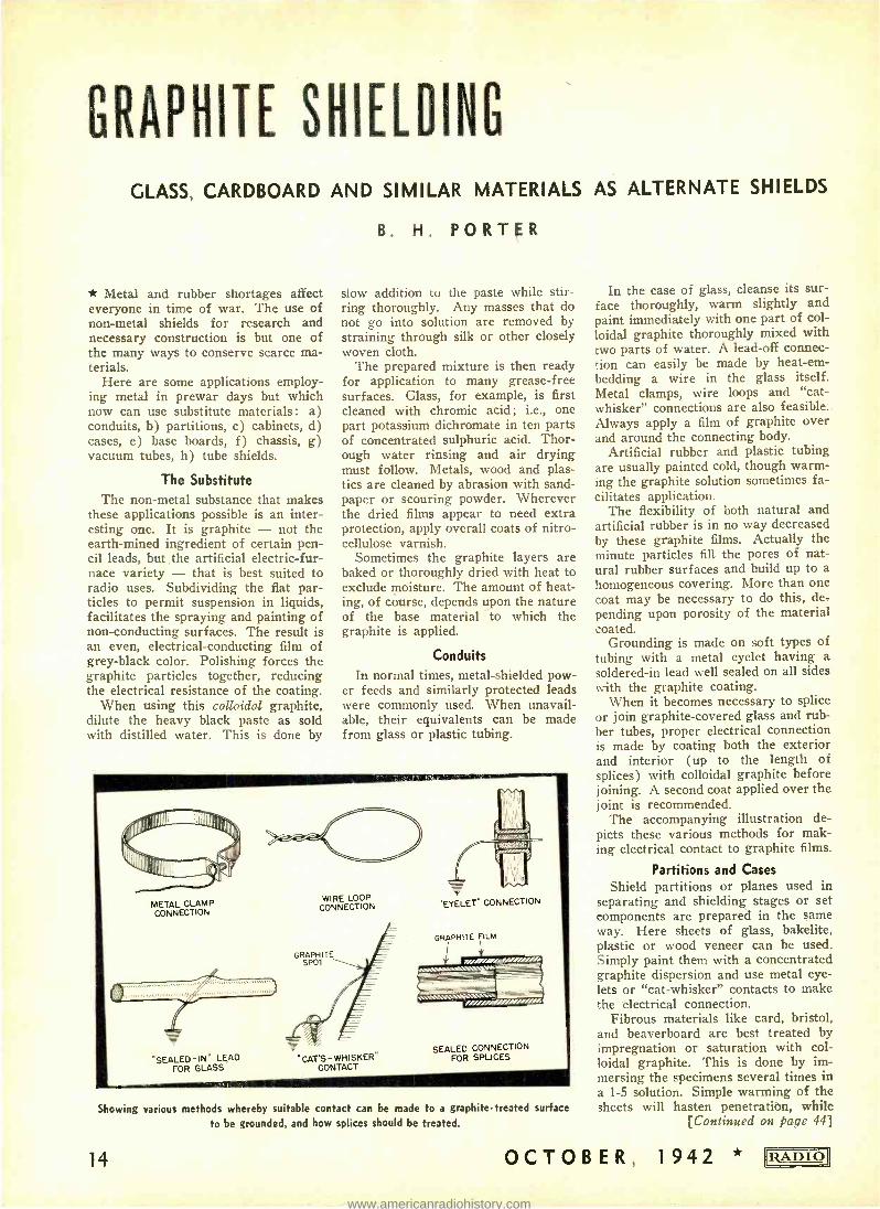
Conduits In normal times, metal -shielded pow-
er feeds and similarly protected leads were commonly used. When unavail- able, their equivalents can be made from glass or plastic tubing.
METAL CLAMP CONNECTION
WIRE LOOP CONNECTION
GRAPHITE SPOT
"EYELET" CONNECTION
"SEALED -IN" LEAD FOR GLASS
"CAT'S-WHISKER" CONTACT
SEALED CONNECTION FOR SPLICES
Showing various methods whereby suitable contact can be made to a graphite- treated surface
to be grounded, and how splices should be treated.
14
In the case of glass, cleanse its sur- face thoroughly, warm slightly and paint immediately with one part of col- loidal graphite thoroughly mixed with two parts of water. A lead -off connec- tion can easily be made by heat -em- bedding a wire in the glass itself. Metal clamps, wire loops and "cat - whisker" connections are also feasible. Always apply a film of graphite over and around the connecting body.
Artificial rubber and plastic tubing are usually painted cold, though warm- ing the graphite solution sometimes fa- cilitates application.
The flexibility of both natural and artificial rubber is in no way decreased by these graphite films. Actually the minute particles fill the pores of nat- ural rubber surfaces and build up to a homogeneous covering. More than one coat may be necessary to do this, de- pending upon porosity of the material coated.
Grounding is made on soft types of tubing with a metal eyelet having a
soldered -in lead well sealed on all sides with the graphite coating.
When it becomes necessary to splice or join graphite- covered glass and rub- ber tubes, proper electrical connection is made by coating both the exterior and interior (up to the length of splices) with colloidal graphite before joining. A second coat applied over the joint is recommended.
The accompanying illustration de- picts these various methods for mak- ing electrical contact to graphite films.
Partitions and Cases
Shield partitions or planes used in separating and shielding stages or set components are prepared in the same way. Here sheets of glass, bakelite, plastic or wood veneer can be used. Simply paint them with a concentrated graphite dispersion and use metal eye- lets or "cat- whisker" contacts to make the electrical connection.
Fibrous materials like card, bristol, and beaverboard are best treated by impregnation or saturation with col- loidal graphite. This is done by im- mersing the specimens several times in a 1 -5 solution. Simple warming of the sheets will hasten penetration, while
[Continued on page 44]
OCTOBER, 1942 RADIO
www.americanradiohistory.com
THIRTEEN WAYS TO
PROLONG TUBE LIFE
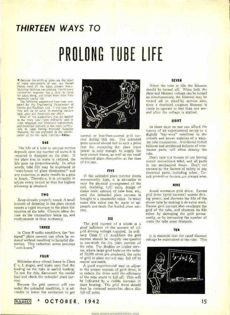
* Because transmitting tubes are the heart of many instruments of war, our Armed Forces need all the tubes present manu- facturing facilities can produce. Hence every transmitter engineer has a duty to nurse his tubes along, and obtain from them their maximum useful life.
The following suggestions have been pre- pared by the Engineering Department of Heintz and Kaufman, Ltd., in the hope that they will be of value in assisting vacuum tube users and Americas war effcrt.
Most of the suggestions may be applied to the many tube types ordinarily used in radio telegraph and telephone transmitters, and broadcast stations; a few apply particu- larly to tubes having thoriated tungsten filaments. All are pertinent to the contin- uation of civilian radio services.- Editor.
ONE
The life of a tube in normal service depends upon the number of watts it is required to dissipate on the plate. If the plate loss in watts is reduced, the life goes up proportionately. In other words, tube life may be expressed as "watt -hours of plate dissipation," and any reduction in watts results in a gain in hours. Therefore, it is advisable to adjust every circuit so that the highest efficiency is obtained.
TWO
Keep circuits properly tuned. A small amount of detuning in the plate circuit causes a rapid increase in the plate dis- sipation of the tube. Circuits often de- tune as the transmitter heats up, and readjustment is then necessary.
THREE
In Class B audio amplifiers, the "no- signal" plate current can often be re- duced without resulting in harmful dis- tortion. This reduction saves precious "watt- hours."
FOUR
Minimize stray circuit losses in Class C r. f. stages, and make sure that the loading on the tube is useful loading. To test for this, disconnect the useful load and check the unloaded plate cur- rent.
Because the grid current will rise under the unloaded condition, it is ad- visable to lower the excitation to get
RADIO
normal or less- than -normal grid cur- rent during this test. The unloaded plate current should fall to such a point that the remaining d.c. plate input power is only enough to supply the tank circuit losses, as well as the small incidental plate dissipation at the time of the test.
FIVE
If the unloaded plate current seems unreasonably high, it is advisable to vary the physical arrangement of the coil, shielding, L/C ratio, design of choke coils, amount of tube bias, etc., until the unloaded plate current is brought to a reasonable value. In many cases this value can be made to ap- proach one -tenth the loaded plate cur- rent.
SIX
The grid current of a triode is a good indicator of the amount of r.f. grid driving voltage required. In ordi- nary Class C r.f. amplifiers the grid current should be roughly one -quarter to one -sixth the d.c. plate current of the tube. For doubler or tripler serv- ice, where large grid leaks on the order of 50,000 ohms are employed, the ratio of grid to plate current may fall off to nearer one -tenth.
A good experimental way to adjust to the proper amount of grid drive, is to reduce the drive until the efficiency of the tube starts to fall off. This will be indicated by a visible increase in plate heating. The grid drive should then be restored somewhat above this fall -off point.
* OCTOBER, 1942
SEVEN
When the tube is idle the filament should be turned off. When both the plate and filament voltage can be turned on simultaneously, the filament may be turned off in stand -by service also, since a thoriated tungsten filament is ready to operate in less than one sec- ond after the voltage is applied.
EIGHT
In these days no one can afford the luxury of an experimental set -up or a slightly "hay- wire" condition in the circuits and power supplies of a vacu- um tube transmitter. Accidental circuit failures and accidental failures of com- ponent parts, will often destroy the tube.
Don't take the chance of not having circuit connections solid, and all parts in top mechanical shape. Don't cut corners on the factors of safety in any electrical parts, including tubes. Cir- cuit protective devices are always wise.
NINE
Avoid excessive grid drive. Excess grid drive (grid current) wastes driv- ing power, and shortens the life of the driver tube by making it do extra work. Excess grid current also overheats the grid of the tube, and shortens its life either by damaging the grid perma- nently, or by increasing the number of watts the tube must dissipate.
TEN
It is essential that the rated filament voltage be maintained at the tube. This
15
www.americanradiohistory.com
voltage should be measured at the socket, and should not deviate more than plus or minus 5% from the rated value.
The life of a thoriated tungsten fila- ment will be reduced to two -thirds of normal if the filament voltage is per- mitted to run 10% above its rated value. At 10% below rated value, the emission from the filament may fall off due to failure to diffuse enough thori- um to the surface of the filament to maintain emission. A drop in emission may cause severe overheating of the plate, with a consequent reduction in the life of the tube, or even complete failure.
ELEVEN
Make good electrical connections to the tube. At ordinary frequencies, the standard connector clips are satisfac- tory. At ultra -high frequencies the
charging currents into the inter -elec- trode capacities become large enough so that special care must be taken. A split connector of aluminum or plated brass, with the two halves held together by a silver or similarly plated ex- ternal spring, which will remain good at 200 to 300 degrees C., will prove most satisfactory.
TWELVE
The efficiency of a Class C r. f. amplifier is largely dependent upon the conditions in the grid circuit. The d.c. bias voltage is the total of the voltages developed in the grid -leak resistor, the cathode resistor and the voltage sup- plied by the fixed bias source.
The grid bias voltage should be con- siderably greater than that required for cut -off. The exact value of total bias voltage is not critical so long as it is ample. A good value to approxi- mate is that listed on the data sheets for the particular type of tube and type of service.
In ordinary Class C amplifier serv- ice, a very desirable arrangement of d.c. grid bias voltage is one consisting of enough fixed bias to prevent the flow of plate current when all r. f. excita- tion voltage is removed -with the bal- ance of the bias supplied by the IR drop in the resistor.
Such an arrangement provides ade- quate protection, and at the same time
gives the highly. desirable automatic action of a grid -leak resistor.
THIRTEEN
The electrical instability of r.f. cir- cuits increases the probability of dam- age and overload to a tube. Parasitic oscillations can also cause damaging overloads, as well as inconvenience. Nearly any parasitic oscillation can be prevented. A good way to isolate and cure parasitics in an amplifier is to :
a- Remove the normal excitation b- Remove all fixed bias c -Lower the plate voltage until the
plate loss due to the static plate cur- rent flowing does not exceed the rated tube dissipation.
Under these conditions there should be no parasitic oscillation at any posi- tion of the tuning dials. A parasitic oscillation will be readily indicated by the presence of grid current. If such oscillations occur, then:
a -Find the frequency of the para- sitic
b- Determine the parasitic circuit superimposed on the normal r.f. cir- cuits.
c- Adjust the parasitic circuit, de- creasing its excitation voltage until the oscillation ceases. Such changes need not seriously affect normal circuits.
(Reprints of "Thirteen Ways to Pro- long Tube Life" in booklet form are available for the asking, from Heintz & Kaufman, Ltd., South San Francisco, Calif.)
GROUND SYSTEM AT KMPC
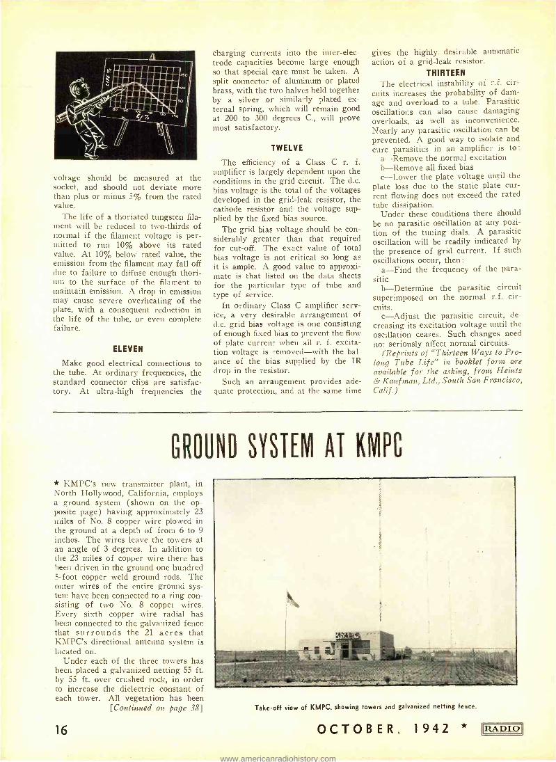
* KMPC's new transmitter plant, in North Hollywood, California, employs a ground system (shown on the op- posite page) having approximately 23 miles of No. 8 copper wire plowed in the ground at a depth of from 6 to 9 inches. The wires leave the towers at an angle of 3 degrees. In addition to the 23 miles of copper wire there has been driven in the ground one hundred 5 -foot copper weld ground rods. The outer wires of the entire ground sys- tem have been connected to a ring con- sisting of two No. 8 copper wires. Every sixth copper wire radial has been connected to the galvanized fence that surrounds the 21 acres that KMPC's directional antenna system is located on.
Under each of the three towers has been placed a galvanized netting 55 ft. by 55 ft. over crushed rock, in order to increase the dielectric constant of each tower. All vegetation has been
[Continued on page 38]
16
Take -off view of KMPC, showing towers and galvanized netting fence.
OCTOBER, 1942 !IZADIO
www.americanradiohistory.com
t
.hll. artó For Future Jr, t M
V \ \ 1
\ \
\ \ V
1 _ -
\ r
' I
i .
i /
\`1 \z:ì:_,:.:'"! / If
1 y
`
1\
Geh
\.!Ï::;.';;i.:.%`:F:i+.`
, -440.161: --- \
:: \\-, : :: : \\,
1 ' '`
a r S1iYr t
____-- i
\
%
. \
N \, \ \\
:fal:'i
r
i.'''
` 41,
` ` `_ ` `
_\ j, _ s _ - _ -_ -_ ` ¡ /, h i , % r ----- Tii yron IIA!
; ,:
\I______-
\ \ \ S .- / <r i dán s,/t 1.,...,..-- / j, ' 1 i j / i / /
A
`
I
' I a ' / / , l l l; / f r `
m tle ua
\ \ 1-,
w , 1
el
y //,/// ,' / ! / ! l Il1 l I
I
I
i VBW \De' l
I
350' « 700'.
----.--150'
A
3
C
-D
F
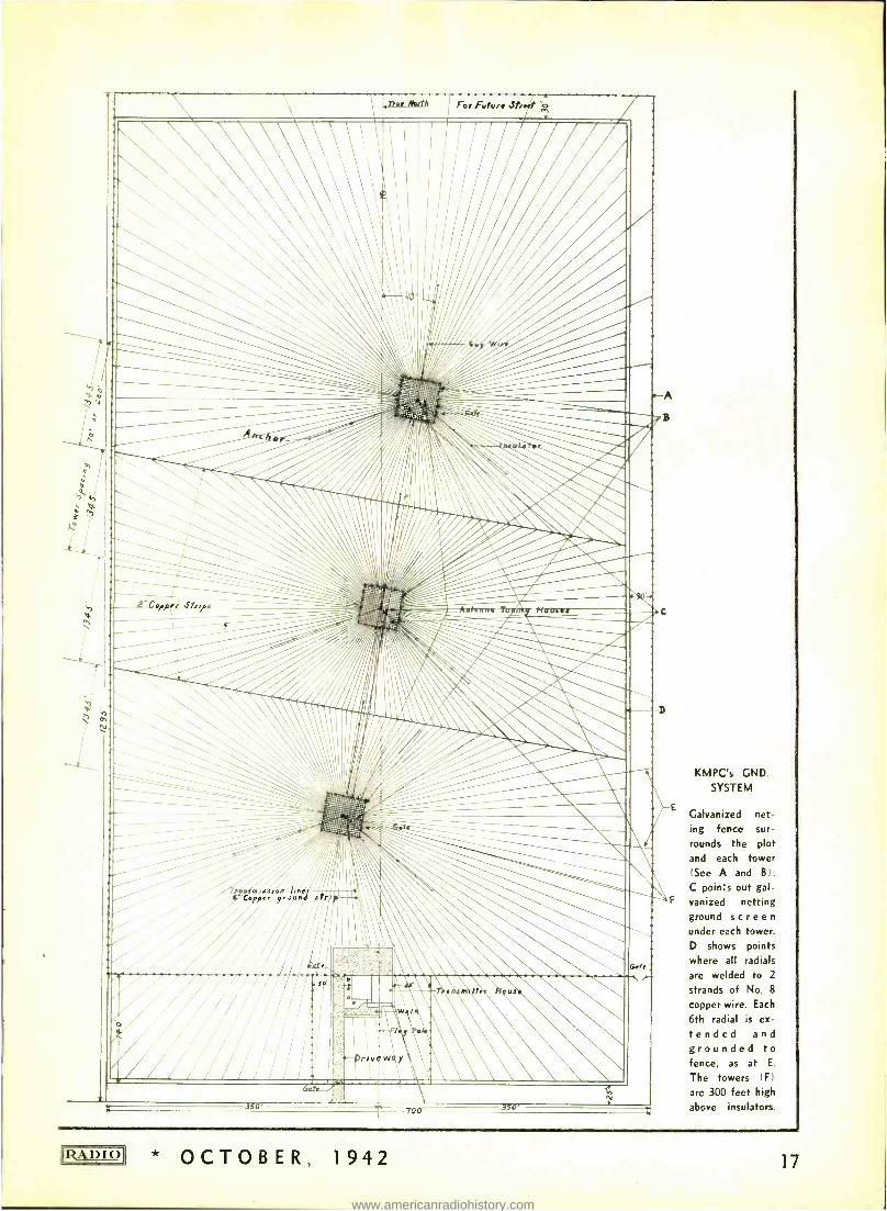
KMPC's GND.
SYSTEM
Galvanized net -
ing fence sur-
rounds the plot and each tower (See A and B).
C points out gal- vanized netting ground screen under each tower. D shows points where all radials
are welded to 2
strands of No. 8
copper wire. Each
6th radial is ex-
tended and grounded to fence, as at E.
The towers IF)
are 300 feet high
above insulators.
* OCTOBER, 1942 17
www.americanradiohistory.com
Q. & A. STUDY GUIDE
228. A transformer having a. center - tapped secondary is used with a full - wave rectifier with the transformer center tap for the common negative re- turn; if the same transformer were connected for full -wave bridge rectifi- cation, what would be the effect upon the output voltage?
With the same transformer con- nected for full -wave bridge rectifica- tion, the output voltage would be dou- bled; in this case, with the center tap unused, the total transformer voltage is available for the load, rather than one -half its voltage when the center tap is used as the common negative re- turn.
229. If a high- voltage rectifier sys- tem were changed from a full -wave, center - tapped transformer connection to a bridge- connected, full -wave recti- fier system using the same high- voltage transformer, what changes in the filter components would be necessary?
With a change to the bridge connec- tion, the output voltage would be doubled; therefore it would be required that filter condensers be used having double the working voltages of those originally employed.
230. List the main advantage of a full -wave rectifier as compared to a half -wave rectifier.
The output voltage of the full -wave rectifier is twice the line frequency, the current is more uniform, and is there- fore more easily filtered and regulated. Also, the tendency of a power trans- former in a half -wave rectifier to be- come saturated is eliminated.
FIG. 1. HALF -WAVE, THREE -PHASE
RECTIFIER.
18
Theory and Practice
231. Using a plate transformer hav- ing a secondary voltage of 500 volts r.m.s. in a single -phase half -wave rec- tifier working into a condenser input filter, what should be the minimum al- lowable d.c. working voltage rating for the filter input condenser?
The safe minimum working voltage for the input condenser in a condenser - input filter is equal to 1.4 times the r.m.s. voltage output of the rectifier. As an additional safety factor, neglect the drop in voltage in the rectifier tube. Thus the working voltage of the con- denser should be 1.4 X 500, or 700.
232. A single -phase power transfor- mer, with secondary center tapped, has a total secondary voltage of 2000 volts r.m.s. When used in a full -wave rec- tifying circuit with condenser input fil- ter, the filter input condenser should have what continuous d.c. working - voltage rating?
The transformer voltage available for the load is one -half the total trans- former voltage in the manner used. The condenser working voltage should therefore he 1.4 X 1000, or 1400 volts.
233. Why may a transformer not be used with direct current?
A transformer will not operate when supplied with direct current, since a circuit has the property of induction only when the e.m.f. set up in the cir- cuit is due to a change in current through the circuit. A varying current is therefore essential.
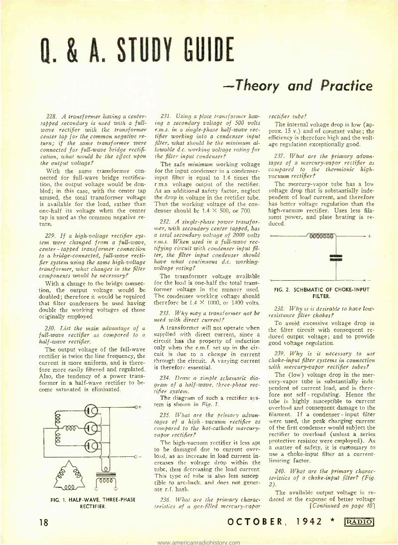
234. Draw a simple schematic dia- gram of a half -wave, three -phase rec- tifier system.
The diagram of such a rectifier sys- tem is shown in Fig. 1.
235. What are the primary advan- tages of a high. - vacuum rectifier as compared to the hot -cathode mercury- vapor rectifier?
The high- vacuum rectifier is less apt to be damaged due to current over- load, as an increase in load current in- creases the voltage drop within the tube, thus decreasing the load current. This type of tube is also less suscep- tible to arc -back, and does not gener- ate r.f. hash.
236. What are the primary charac- teristics of a gas -filled mercury -vapor
rectifier tube? The internal voltage drop is low (ap-
prox. 15 v.) and of constant value; the efficiency is therefore high and the volt- age regulation exceptionally good.
237. What are the primary advan- tages of a mercury -vapor rectifier as compared to the thermionic high. - vacuum rectifier?
The mercury -vapor tube has a low voltage drop that is substantially inde- pendent of load current, and therefore has better voltage regulation than the high- vacuum rectifier. Uses less fila- ment power, and plate heating is re- duced.
T
+
FIG. 2. SCHEMATIC OF CHOKE -INPUT FILTER.
238. Why is it desirable to have low- resistance filter chokes?
To avoid excessive voltage drop in the filter circuit with consequent re- duced output voltage; and to provide good voltage regulation.
239. Why is it necessary to use choke -input filter systems in connection with mercury -vapor rectifier tubes?
The (low) voltage drop in the mer- cury -vapor tube is substantially inde- pendent of current load, and is there- fore not self - regulating. Hence the tube is highly susceptible to current overload and consequent damage to the filament. If a condenser - input filter were used, the peak charging current of the first condenser would subject the rectifier to overload (unless a series protective resistor were employed). As a matter of safety, it is customary to use a choke -input filter as a current - limiting factor.
240. What are the primary charac- teristics of a choke -input filter? (Fig. 2).
The available output voltage is re- duced at the expense of better voltage
[Continued on page 40]
OCTOB ER, 1942 * RADIO
www.americanradiohistory.com
BROADCAST STATION
MAINTENANCE & OPERATION
PART II * The daily routines for the six oper- ator shifts were covered in Part I of this series. In addition to these rou- tines, periodic checks are made weekly, the checks being spread out over the seven days, as follows:
"C" and "F" Shift, First Week Sunday: 30. Measure a -m and f -m noise, swing
versus lA panel input meter read- ings, and distortion.
31. Check and clean mikes, mike stands, mike jacks and connectors.
32. Check and clean faders, pots and selector switches in Speech Input Equipment.
33. Check and clean relays, monitor selectors, and keys.
Monday: 34. Check and clean targets in water
hose fittings, replace when neces- sary.
35. Check all mechanical controls of 50 -kw stage, and grease and oil same.
Tuesday: 36. Check for scale formation on 899-
A filament studs and connectors. Clean only when necessary.
h.1r.n 1NM
NEVO 01tall..
CHARGES
p1e' 1 ..
a...e.....
RADIO
FIG.7
C. H. WESSER Chief Engineer, W45D
37. Check and clean filament connec- tions of 869 Rectifiers.
38. Check and clean all air filters, and replace when necessary.
Wednesday: 39. Clean and polish all patch cords. 40. Polish all panels and clean tops of
Control Desk and Turntable Desk. 41. Dust all equipment on 46th floor.
Thursday: 42. Clean 23 -B, Bays 1 through 8,
with vacuum cleaner and dust cloth.
Friday: 43. Check all electrical and mechani-
cal connections on 46th floor. Check all electrical and mechani- cal connections on 45th floor.
45. Clean, grease and oil the follow- ing items: a) filament m.g. set, b) blower motor and blower, c) fan motor and fan, d) spray motor and pump, e) pump motors and pumps, f) damper motors and dampers, g) voltage regulator.
Saturday: 46. Operate Transmitter for 30 min-
utes with a.c. on filaments instead of d.c., and on spare water pump.
47. During this 30- minute period, do the following: a) check pump
44.
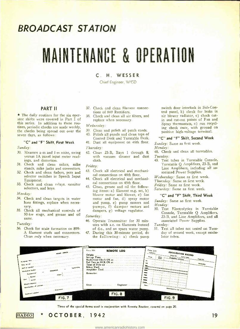
Form 3216 REMOTE LOG Origin Set -up Time Radio Line Check OK at Fed Test to MCR OK at Type of Pick -up Mikes Used Amplifier Used
Remarks:
Date - Engineer
FIG. 8
switch door interlock in Sub -Con- trol panel, b) check for leaks in air blower radiator, c) check cut - in and cut -out points of Fan and Spray thermostats, c) run recycl- ing check once, with ground on positive high -voltage terminal.
"C" and "F" Shift, Second Week
Sunday: Same as first week. Monday: 48. Check and clean all turntables. Tuesday: 49. Test tubes in Turntable Console,
Turntable Q Amplifiers, 23 -B, and Line Amplifiers, including all as- sociated Power Supplies.
Wednesday: Same as first week. Thursday: Same as first week. Friday: Same as first week. Saturday: Same as first week.
"C" and "F" Shift, Third Week
Sunday: Same as first week. Monday: 50. Test Electrolytics in Turntable
Console, Turntable Q Amplifiers, 23 -B, and Line Amplifiers, and all associated Power Supplies.
Tuesday: 51. Test all tubes not tested on Tues-
day of second week, except modu- lator tubes.
porn, 3215 Resole:
loo
ooe zi000
eiboo
nos lavo
Pete
I
EQUALIZATION RECORD
... L....... ....'
.
1.......... .. ...../1..'
;L .:.: ... ... ................../.. .
i
..nr.ue os on
'~. a,
FIG.9
Three of the special forms used in conjunction with Remote Routine, covered on page 20.
* OCTOBER, 1942 19
www.americanradiohistory.com
Wednesday: Same as first week. Thursday: Same as first week. Friday: Same as first week. Saturday: Same as first week.
"C" and "F" Shift, Fourth Week Sunday: Same as first week. Monday: 52. Test all Electrolytics, except those
tested on Monday of third week. Tuesday: 53. General maintenance. Wednesday: Same as first week. Thursday: Same as first week. Friday: Same as first week. Saturday: Same as first week.
Quarterly Maintenance Quarterly Maintenance items, to be
performed on Tuesday of fourth week period of the following months : No- vember, February, May, August: 54. Check and clean Spray water res-
ervoir. 55. Check entire water -cooling system
for scale formation. Note: If for- mation is excessive, and cannot be cleaned completely, take water sample for analysis.
56. Thoroughly clean all insulators in Doghouse.
57. Thoroughly clean Doghouse. 58. Check for leaks in Doghouse, and
repair if necessary. Figs. 2, 3, 4, 5, and 6 in Part I show,
respectively the Daily Log, Modulator - I.P.A.- Driver Log, 50 -kw Amplifier Log, Speech Input Meter Readings Log, and Frequency -Measurements Log.
Remote Routine The handling of remotes is covered
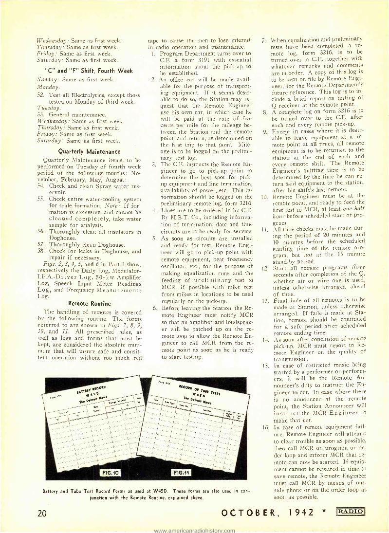
by the following routine. The forms referred to are shown in Figs. 7, 8, 9, 10, and 11. All prescribed rules, as well as logs and forms that mast be kept, are considered the absolute mini- mum that will insure safe and consis- tent operation without too much red
rape to cause the men to lose interest in radio operation and maintenance.
1. Program Department turns over to C.E. a form 3191 with essential information about the pick -up to be established.
2. An office car will be made avail- able for the purpose of transport- ing equipment. If it seems desir- able to do so, the Station may re- quest that the Remote Engineer use his own car, in which case he will be paid at the rate of five cents per mile for the mileage be- tween the Station and the remote point, and return, as determined on the first trip to that point. Mile- age is to be logged on the prelimi- nary test log.
3. The C.E. instructs the Remote En- gineer to go to pick -up point to determine the best spot for pick- up equipment and line termination, availability of power, etc. This in- formation should be logged on the preliminary remote log, form 3216.
4. Lines are to be ordered in by C.E. By M.B.T. Co., including informa- tion of termination, date and time circuits are to be ready for service.
5. As soon as circuits are installed and ready for test, Remote Engi- neer will go to pick -up point with remote equipment, beat frequency oscillator, etc., for the purpose of making equalization runs and the feeding of preliminary test to MCR, if possible with mike test from mikes in locations to be used regularly on the pick -up.
6. Before leaving the Station, the Re- mote Engineer must notify MCR so that an amplifier and loudspeak- er will be patched up on the re- mote loop to allow the Remote En- gineer to call MCR from the re- mote point as soon as he is ready to start testing.
Battery and Tube Test Record Forms as used at W45D. These forms are also used in con-
junction with the Remote Routine, explained above.
20
7. When equalization and preliminary tests have been completed, a re-
mote log, form 3216, is to be
turned over to C.E., together with whatever remarks and comments are in order. A copy of this log is
to be kept on file by Remote Engi- neer, for the Remote Department's future reference. This log is to in- clude a brief report on testing of
O receiver at the remote point. 8. A complete log on form 3216 is to
be turned over to the C.E. after each and every remote pick -up.
9. Except in cases where it is desir- able to leave equipment at a re- mote point at all times, all remote equipment is to be returned to the station at the end of each and every remote shift. The Remote Engineer's quitting time is to be
determined by the time he can re- turn said equipment to the station, after his shift's last remote.
10. Remote Engineer must be at the remote point, and ready to feed the first test to MCR, at least one -half hour before scheduled start of pro- gram. All time checks must be made dur- ing the period of 20 minutes and 10 minutes before the scheduled starting time of the remote pro- gram, but not at the 15 minute stand -by period.
12. Start all remote programs three seconds after completion of the Q,
whether air or wire one is used, unless otherwise arranged ahead of time.
13. Final fade of all remotes is to be
made at Station, unless otherwise arranged. If fade is made at Sta- tion, remote should be continued for a safe period after scheduled remote ending time.
14. As soon after conclusion of remote pick -up, MCR must report to Re- mote Engineer on the quality of transmission.
15. In case of restricted music being started by a performer or perform- ers, it will be the Remote An- nouncer's duty to instruct the En- gineer to cut. In case where there is no announcer at the remote point, the Station Announcer will instruct the MCR Engineer to make that cut.
16. In case of remote equipment fail- ure, Remote Engineer will attempt to clear trouble as soon as possible, then call MCR on program or or- der loop and inform MCR that re- mote can now be started. If equip- ment cannot be repaired in time to save remote, the Remote Engineer must call MCR by means of out- side phone or on the order loop as soon as possible.
11.
OCTOBER, 1 942 RADIO]
www.americanradiohistory.com
17. In the case where lines stay in service for more than four weeks, a check on equalization must be made on such lines every four weeks from day the original equalization was made.
18. All movement of remote equip- ment must be at once recorded on the board provided for that pur- pose.
19. No defective equipment is to be returned to stock without first hav- ing been repaired.
20. Each and every tube should be checked at least once every two weeks, and test readings logged on form 3213, and kept in ring binder provided for that purpose.
21. Faders, switches, etc., must be cleaned with carbon tetrachloride, and given a thin coat of white vaseline, at least once each month. Tubes of vaseline should be used for cleanliness.
22. An accurate log of time of actual use of all batteries must be kept on form 3214, and filed in a ring bind- er provided for that purpose.
23. All twist -lock fittings (male and female) must be cleaned with car- bon tetrachloride at least once a month, and a thin coat of white vaseline applied.
24. Remote Engineer who returns re- mote equipment to stock must clean all such equipment before doing so.
25. All electrical and mechanical con- nections should he checked at least once a week.
26. Frequency runs must he made through each and every channel of each remote amplifier at least once every two weeks, and on same fre- quencies on which equalization runs are made. Frequency runs must be recorded on forni 3215 and filed by Remote Engineer in file provided for that purpose.
27. Remote Engineer will at all times, when loop is not in use, keep a short on same at remote point, for the purpose of making resistance checks on loops by the MCR En- gineer. Also make sure that re- mote loop, even when shorted, is not grounded at remote end.
28. It will he the duty of the MCR En- gineer to check remote loops for resistance, shorts, opens and grounds, and record such checks on the forni provided. This should be done on new loops at the time of installation, and rechecks made every four weeks thereafter. Simi- lar checks should he made on each loop immediately prior to setting up a remote. On loops to be used on Sunday, these checks should not he made later than the preceding Saturday. On weekday remotes
RADIO
W45D -THE DETROIT NEWS DATE 19 TO Engineering Department
Report of Broadcasting Performance DAY
Original Program Interruptions and Schedule Departures
PROGRAM ORIGIN DURATION TIME NATURE AND RESPONSIBILITY
Carrier Time
Program Time Signed
FIG.12
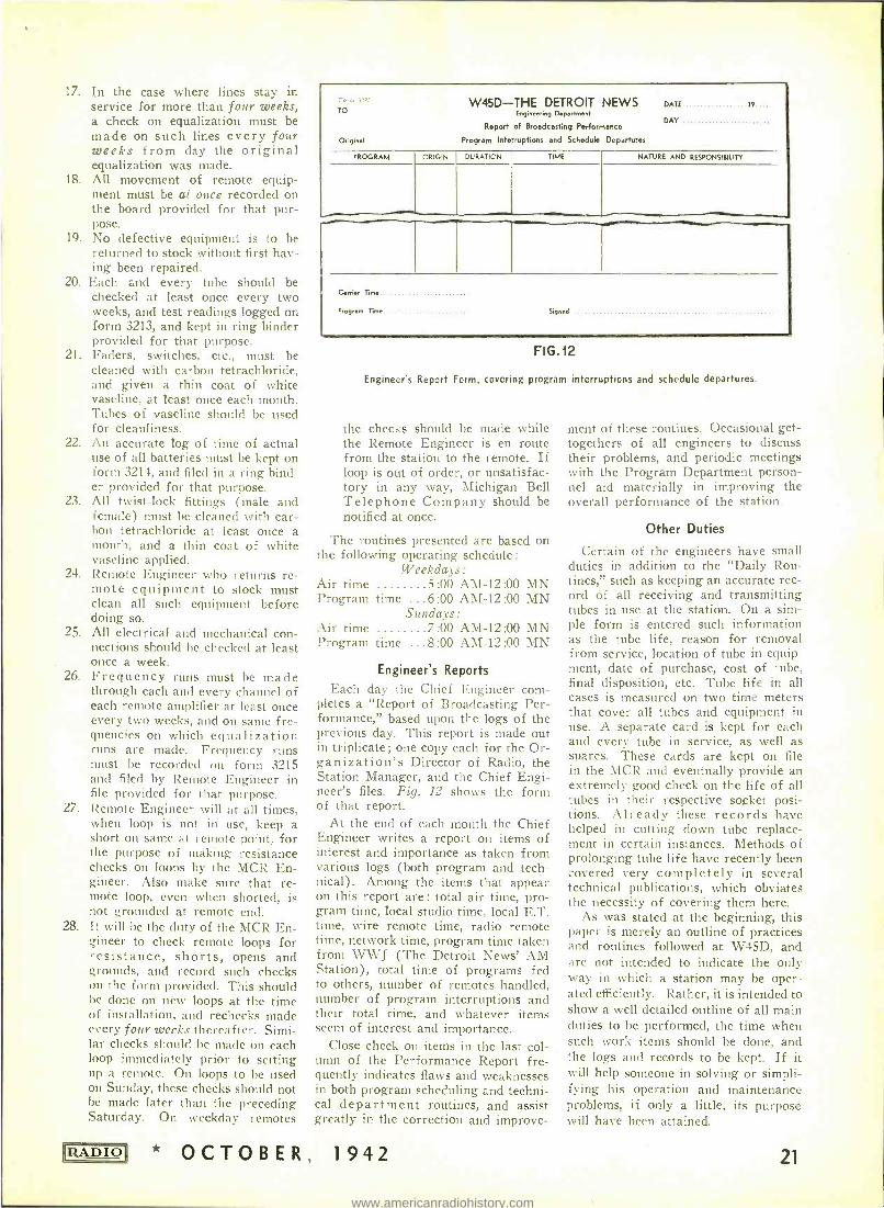
Engineer's Report Form, covering program interruptions and schedule departures.
the checks should be made while the Remote Engineer is en route from the station to the remote. If loop is out of order, or unsatisfac- tory in any way, Michigan Bell Telephone Company should be notified at once.
The routines presented are based on the following operating schedule:
Weekdays: 5.00 AM -12:00 MN
...6:00 AM -12:00 MN n9: d ais :
7 00 AM -12:00 MN ...8:00 AM -12:00 MN
Air time Program
Air time Program
time S
time
Engineer's Reports
Each day the Chief Engineer com- pletes a "Report of Broadcasting Per- formance," based upon the logs of the previous day. This report is made out in triplicate; one copy each for the Or- ganization's Director of Radio, the Station Manager, and the Chief Engi- neer's files. Fig. 12 shows the form of that report.
At the end of each month the Chief Engineer writes a report on items of interest and importance as taken from various logs (both program and tech- nical). Among the items that appear on this report are: total air time, pro- gram time, local studio time, local E.T. time, wire remote time, radio remote time, network time, program time taken from WWJ (The Detroit News' AM Station), total time of programs fed to others, number of remotes handled, number of program interruptions and their total time, and whatever items seem of interest and importance.
Close check on items in the last col- umn of the Performance Report fre- quently indicates flaws and weaknesses in both program scheduling and techni- cal department routines, and assist greatly in the correction and improve-
* OCTOBER, 1942
ment of these routines. Occasional get - togethers of all engineers to discuss their problems, and periodic meetings with the Program Department person- nel aid materially in improving the overall performance of the station.
Other Duties
Certain of the engineers have small duties in addition to the "Daily Rou- tines," such as keeping an accurate rec- ord of all receiving and transmitting tubes in use at the station. On a sim- ple form is entered such information as the tube life, reason for removal from service, location of tube in equip- ment, date of purchase, cost of tube, final disposition, etc. Tube life in all cases is measured on two time meters that cover all tubes and equipment in use. A separate card is kept for each and every tube in service, as well as spares. These cards are kept on file in the MCR and eventually provide an extremely good check on the life of all tubes in their respective socket posi- tions. Already these records have helped in cutting down tube replace- ment in certain instances. Methods of prolonging tube life have recently been covered very completely in several technical publications, which obviates the necessity of covering them here.
As was stated at the beginning, this paper is merely an outline of practices and routines followed at W45D, and are not intended to indicate the only way in which a station may be oper- ated efficiently. Rather, it is intended to show a well detailed outline of all main duties to be performed, the time when such work items should be done, and the logs and records to be kept. If it will help someone in solving or simpli- fying his operation and maintenance problems, if only a little, its purpose will have been attained.
21
www.americanradiohistory.com
NOTES ON RECEIVER DESIGN
* The prime requisites of a communi- cations receiver designed for reception at high- and ultra -high frequencies are: sensitivity, stability, high signal - to -noise ratio, and ease of control. A few ideas with regard to improving these essential characteristics are in- corporated in this article.
Sensitivity and Noise
The sensitivity of many communi- cations receivers is far below the ideal, and there are numerous factors that impair the ability of the r.f. stages to bring weak signals up to a useful level. In this respect, the first tuned circuit is the most important insofar as signal - to -noise ratio is concerned, and the first r.f. stage must operate at optimum efficiency for good weak -signal sensi- tivity. The tube used in the first r.f. stage must have a low inherent noise output, and the antenna and first tuned circuit must provide a high degree of selectivity. If the tuned grid circuit has low Q, the discrimination against noise in the entire receiver is reduced considerably.
From the viewpoint of low noise out- put, the type 1851 tube or its equivalent is best suited for use in the first r.f. stage; but this tube has the unfortunate characteristic of loading the grid cir- cuit, due to its low input resistance. If it were not for this detail, the 1851 would prove its worth in a single -ended tuned r.f. stage.
Push -Pull Circuit Grid -circuit loading may be reduced
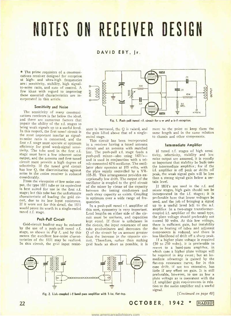
by the use of a push -pull tuned r.f. stage, as shown in Fig 1, and by this means the excellent low -noise charac- teristics of the 1851 may be realized. In this circuit, the grid input resist-
DAVID EBY, Jr.
Fig. 1. Push -pull tuned r.f. circuit for s -w and u -h -f reception.
ance is increased, the Q is raised, and the gain lifted above that of a single - ended stage.
This circuit has been incorporated in a receiver having a tuned antenna circuit and an antenna with matched line. The push -pull r.f. stage feeds a push -pull mixer -also using 1851's- and is used in conjunction with a tri- ode- connected 6F6 oscillator. The oscil- lator plate operates at 105 volts, with the plate supply controlled by a VR- 105-30. This arrangement provides ex- ceptionally low drift. The output of the oscillator is coupled to the grid circuit of the mixer by virtue of the capacity between the tuning condensers and such stray capacity as exists. Coupling is optimum over a wide range of fre- quencies.
In a push -pull tuned r.f. amplifier of this sort, symmetry is very important. Lead lengths on either side of the cir- cuit must be uniform, and capacities kept equal. If there is unbalance in the circuit, the input resistance of one tube predominates and decreases the Q of the circuit by an amount greater than the increase in the opposite cir- cuit. Therefore, rather than making grid leads as short as possible, it is
Fig. 2. Link- coupled i -f band -pass amplifier with 1 -kc. flat -top.
22
o
more to the point to keep them the same length and in the same relation to chassis and other components.
Intermediate Amplifier
If tuned r.f. stages of high sensi- tivity, selectivity, stability and low noise output are assumed, it is equally as important that stability be built into the intermediate amplifier; for if the i.f. amplifier is off peak or drifts off peak, the weak signal gain will be less than a strong signal gain below a cer- tain level.
If 1851's are used in the r.f. and mixer stages, high gain should not be incorporated in the i.f. stages; it is preferable here that lower voltages be used, and the job of bringing a signal up to a useful level left to the a.f. amplifier. In a two -stage transformer - coupled i.f. amplifier of the usual type, the plate voltage should preferably not exceed 50 volts. At this low voltage, there is sufficient gain, but instability due to heating of tubes and adjacent components is reduced, and there is less likelihood of drift off a sharp peak.
If a higher plate voltage is required (50 to 250 volts), it is preferable to revert to a band -pass amplifier, in which case a higher plate voltage will be required in any event; but an im- mediate advantage is gained by the flat -top resonance curve, for in this case drift, if not too extensive, has little if any effect on gain. It is still preferable, however, to use as low a plate voltage as is consistent with the i.f. amplifier gain requirements in rela- tion to the audio amplifier and a useful signal.
[Continued on page 40]
OCTOBER, 1942 RADIO
www.americanradiohistory.com
RADIO DESIGN WORKSHEET No. 6- THEVENIN'S THEOREM
RECOVER INPUT IMPEDANCE
FIG.1
RECEIVER INPUT
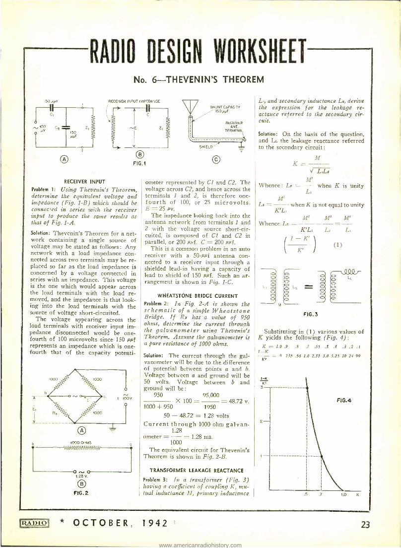
Problem 1: Using Thevenin's Theorem, determine the equivalent voltage and impedance (Fig. 1 -B) which should be connected in series with the receiver input to produce the saine results as that of Fig. 1 -A.
Solution: Thevenin's Theorem for a net- work containing a single source of voltage may be stated as follows : Any network with a load impedance con- nected across two terminals may be re- placed so far as the load impedance is concerned by a voltage connected in series with an impedance. This voltage is the one which would appear across the load terminals with the load re- moved, and the impedance is that look- ing into the load terminals with the source of voltage short -circuited.
The voltage appearing across the load terminals with receiver input im- pedance disconnected would be one - fourth of 100 microvolts since 150 µµf represents an impedance which is one - fourth that of the capacity potenti-
b 1000 OHMS
1.28 V.
0 FIG.2
SHUNT CAPACITY / 150 HNf
RECEIVER ANT.
TERMINAL
SHIELD
ometer represented by Cl and C2. The voltage across C2, and hence across the terminals 1 and 2, is therefore one - fourth of 100, or 25 microvolts. E = 25 µv.
The impedance looking back into the antenna network from terminals 1 and 2 with the voltage source short -cir- cuited, is composed of Cl and C2 in parallel, or 200 µµf. C = 200 µµf.
This is a common problem in an auto receiver with a 50 -µuf antenna con- nected to a receiver input through a shielded lead -in having a capacity of lead to shield of 150 µuf. Such an ar- rangement is shown in Fig. 1 -C.
WHEATSTONE BRIDGE CURRENT
Problem 2: In Fig. 2 -A is shown the schematic of a simple Wheatstone Bridge. If R: has a value of 950 ohms, determine the current through the galvanometer using Thevenin's Theorem. Assume the galvanometer is a pure resistance of 1000 ohms.
Solution: The current through the gal- vanometer will be due to the difference of potential between points a and b. Voltage between a and ground will be 50 volts. Voltage between b and ground will be:
950 95,000 X 100 = - 48.72 v.
1000 + 950 1950
50 - 48.72 = 1.28 volts Current through 1000 -ohm galvan-
1.28 ometer = -- = 1.28 ma.
1000 The equivalent circuit for Thevenin's
Theorem is shown in Fig. 2 -B.
TRANSFORMER LEAKAGE REACTANCE
Problem 3: In a transformer (Fig. 3) !raving a coefficient of coupling K, mu- tual inductance, 31, primary inductance
L,, and secondary inductance La, derive the expression for the leakage re- actance referred to the secondary cir- cuit.
Solution: On the basis of the question, and Li. the leakage reactance referred to the secondary circuit:
M K = - - --
V L,I_a
M' Whence : Ls = -- when K is unity
L, M'
L8 = --- when K is not equal to unity K'L,
M' M° M' Whence LL = - -- _ --
L, L,
KK
-1 FIG.3
(1)
Substituting in (1) various values of K yields the following (Fig. 4) :
K - 1.0 .9 .8 .7 .55 .5 .4 .3 .2 . I 1 -K
0 .235 .56 1.0 2.35 3.0 5.25 10 24 99 K'
t-K KZ 3-
FIG.4
2-
i
.5 1.0 K
RADIO * OCTOBER, 1942 23
www.americanradiohistory.com
NEW PRODUCTS
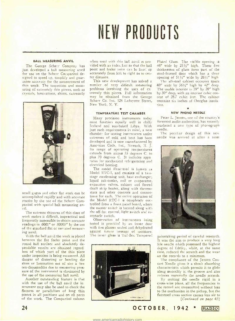
BALL MEASURING ANVIL The George Scherr Company has
just developed a ball measuring anvil for use on the Scherr Comparitol de- signed to speed up, simplify and guar- antee accuracy for the measurement of thin work. The inspection and meas- uring of extremely thin pieces, such as crystals, laminations, shims, extremely
small gages and other flat work can be accomplished rapidly and with accurate results by the use of the Scherr Corn- paritol with special ball measuring an- vil.
The extreme thinness of this class of work makes it difficult, impractical and frequently impossible to obtain accurate readings in .0001" or .00005" by the use of the standard flat or serrated measur- ing anvil.
With the ball anvil the work is placed between the flat feeler point and the round ball surface and absolutely de- pendable results are obtained regard- less of which part of the thin piece under inspection is being measured. All danger of distorting or bending the shim or lamination out of size a few ten -thousandths due to measuring pres- sure of the instrument is eliminated by the use of the measuring ball anvil.
Another outstanding feature is that with the use of the ball anvil the in- strument may also be used to check the flatness or parallelism of long thin pieces in all positions and on all parts of the work. The Comparitol column
24
when used with this ball anvil is pro- vided with an index line so that the ball point and feeler point can be lined up accurately from left to right as to cen- ter distance.
This new development has solved a number of very difficult measuring problems involving the uses of ex- tremely thin pieces. Full information may be obtained from the George Scherr Co. Inc. 128 Lafayette Street, New York, N. Y.
TEMPERATURE TEST CHAMBER
Many precision instruments today must function equally well in chilly Iceland and sun -baked Libya. With just such requirements in mind, a new chamber for testing instruments under extremes of cold and heat has been developed and is now manufactured by American Coils, Inc., Newark, -N. J. Its range of operating temperatures extends from minus 55 degrees C. to plus 70 degrees C. It includes appa- ratus for mechanical refrigerating and electrical heating.
The model illustrated is known as Model RTC -1, and consists of a two - stage condensing unit, heat exchanger, liquid sub -cooler, coil or evaporator, expansion valves, cabinet and forced draft strip heater, along with thermo- stats and other controls and connec- tions for each. The entire operation of the Model RTC -1 is completely con- trolled from a front panel board, where the master switch is located along with the off -fan control, light switch and re- ceptacle switch.
Observation of instruments being tested is provided by an inner door with five glasses sealed and dehydrated against future passage of moisture. The inner glass is Tuf -flex Tempered
Plated Glass. The visible opening is 46" wide by 2172" high. These five thicknesses of glass form part of the steel- framed door which has a clear opening of 51/" wide by 26/" high.
The all -steel cabinet occupies space 83" wide by 56/" high by 42" deep. The usable interior is 59" by 28" high by 30" deep, with an interior cubic con- tent of 28.7 cubic feet. The cabinet contains six inches of fiberglas insula- tion.
NEW PHONO NEEDLE
Peter L. Jensen, one of the country's foremost audio authorities, has recently marketed a new type of phonograph needle.
The peculiar design of this new needle was arrived at after a most
painstaking period of careful research. It was the aim to produce a very long life needle which possessed the highest degree of fidelity, while, at the same time, reduced the scratch and the wear on the records to a minimum.
The compliance of the Jensen Con- cert Needle gives it a shock absorbing characteristic which permits it to glide along smoothly in the groove and also reduces materially the needle scratch.
By making the needle rigid in a cross -wise plane, all the frequencies in the record are transmitted without loss to the mechanism in the pickup, but the flattened cross section causes less air to
[Continued on page 41]
OCTOBER, 1942 RADIO
www.americanradiohistory.com
RADIO
'ay GOODY/ NOW / Co4N L /srFH
TO YOUR NEW ECNØP#'
--
w.
bands. AC/ DC.
Echophone Model EC-1 6 tubes, 3 bands. Tunes from 550 kc. to 30 mc. Beat frequency oscillator. Bandspread logging scale. Self -con- tained speaker. Electrical bandspread on all
/OL D4 -,.
./,
115 -125 volts. ECHOPHONE RADIO CO., 201 EAST 26TH ST., CHICAGO, ILLINOIS
* OCTOBER, 1942 25
www.americanradiohistory.com
F Çt.
C y;tahUb,ap; Y, jL.Y.
Tubes, August, 1942
Amplification, Detection, Sept ' ìe,i n of a Practical Low -Pass
I "ter for 600 Ohm Audio Transmis- Preisman-CO Neaon Lines -S. Helt- Cornni urica.tions, No. 2, February, Vol. 20, No. 10, October, 1940, page 6.
\ Useful Network Theorem -I. Mill - man- Proceedings IRE_, Vol. 28, No. 9, September, 1940, page 407.
Fundamental Transmission Planning of Telephone Networks -B. H. McCurdy -Electrical Communication, Vol. 19, No. 1, 1940, page 18.
Iligh Frequency Transmission Line 'etworks -A. Alford -Electrical Coru-
n.cation.c, Vol. 17, January, 1939, 301.
-. , quali; _ream
27, i.o. 1, J
Single -Sic fel, vision WO( l -Prot, 7, Jury, 19.
Coupling c
Communications, 12.
The Delta Starr Mixer-J N A
Hawkins- Conruncnications, March, 1938, page 20.
Resistance Balancing in Wave Filters -G. Builder- .-1JV_I Technical Review ( Australia), Vol. 3, No. 3, January, 1938, page 83.
Frequency Discrimination by Inverse Feedback -G. II. Fritzinger-Procccd- ings IRE, Vol. 26, No. 2, February, 1938, page 207.
:A New Type of Selective Circuit and Some Applications -H. H. Scott -Pro- ceedings IRE, Vol. 26, No. 2, Febru- ary, 1938, page 226.
On Single and Coupled Circuits Hav- ing Constant Response Band Charac- teristics -Ho - Shou Loh-Proceedings IRE, Vol. 26, No. 4, April, 1938, page 469.
X. RE'l'TENMEYF.- t c.a,m.,far;t!r n C,
FILTERS, EQUALIZERS, NL
l;ril cci "1' )'ads --:A. rani cations, Vol. 21, 1941, page 5.
Insertion Loss in Filters -Britz & Gru- enberg- Electronics, Vol. XIV, March, 194'_, page 45.
Radio Frequency Matching Sections - A. C. Omberg -Electronics, Vol. XIV, January, 1941, page 43.
Attenuator Design -D. Espy-Elec- tronics, Vol. XIV, November, 1941, page 51.
Phase Shifting Up to 360 Degrees - F. A. Everest- Electronics, Vol. XIV, Novemb!r, 1941, page 46.
The Band Pass Effect -S. P. Chakra- varti- Wireless Engineer, Vol. XVIII, No. 210, March, 1941, page 103.
Natural and Re' 'pant Frequencies Coupled Circuits, Wireless r_:Ongincer,
Vol. XVIII, No. 213, `rne, '1, page 221.
Coupling Circuits as B.,nd -Pass Filters --E. H. Sandeman- Wireless Engi- neer, Vol. XVIII, No. 216, September, 1941, page 361.
Speaking of Crystal Filters -I. E. AVill-
son- Cornunrnicotions, Vol. 21, No. 4,
.April, 1941, page 18.
Filter Design -L. J. Giacoletto-Conr- inunications, Vol. 21, No. 8, August, 1941, page 14.
Simple Quartz Crystal Filters of Vari- able Bandwidth -G. Builder and J. E. Benson -AhWA Technical Review, Vol. 5, No. 3, February, 1941, page 93.
Resistance Networks -C. D. Colehester and M. W. Gough -Wireless Engineer, Vol. XVII, No. 200, May, 1940, page 206.
Transversal Filters-H. E. Kellman- Proceedings IRE, Vol. 28, No. 7, July, 1940, page 302.
LIY
of Four -T tr,, ;per -Phil. ìla. .'ember, 19- 1, t,.t
Used Pads -A. She: -s, Vol. XIII, April,
26
by Predistortion- 'cccdings IRE, Vol.
039, page 22.
Theory with . M. Holly - 'ol. 27, No.
, ^tt- 1938, p< ;e
V
trir
ol. 26,
J. A Method of _. -_ ,, .
Networks -\V. A. Edson- Proceed- ings IRE, Vol. 26, No. 7, July, 1938, page 877. Transients of Resistance -Terminated Dissipative Lose - Pass and High igh - Pass Electric Wave Filters-NV. Chu and Chung -Kwci Chang - Proceedings IRE, Vol. 26, No. 10, October, 1938, page 1266.
Crystal Channel Filters fo- the Cable Carrier System -C. E. Lan -Bell Sys- tem Tech. Jour., Vol. XV , Jar ; ;ary, 1938, page 125.
Variable Equalizers - N. \V. ,;t'de - Bell S_vstcrn Tech. four., Vol. XVII, April, 1938, page 229.
Some Notes on Tuned Ce . Circuits - - --C. B. Aiken- Courra. Broadcast Engineering, Vol. 4, Ala: .r, 1037, page
Two-Terminal Equalizers E. Smith -Comm. (i Broadcast ' ragi:rec,iug, Vol. 4, No. 3, March, page 1C
General Equalizer The,,. Two Ter- minal and Constant I:esi ce Struc-
rrc, _llarconi Revic7c, Ja- - -Feh- arv, 1937, page 20.
Curves for Tuned Trar Maynard -E:cc Ironic.:, February, 1937, page 15.
A \Vide -Band Tuner -\V. N. \Veeden -Electronics, February, 1937, page 19.
Resistance Value for Multiple Pads - F. Wheeler-Electronics, March, 1937, page 33.
Miser Circuits -: \. Preisman - Com- munications, June, 1937, page 9.
Some Pad Tables-R. S. Hashind - Coni,nunications, August, 1937, page 12.
Two -Mesh Tuned Coupled Circuit Fil - ters-C. B. Aiken -Proceedings IRE, Vol. 25, No. 2, February, 1937, page 230.
Lattice :Attenuating Networks -Guy C. Orner, Jr.- Proceedings IRE, Vol. 25,
[Continued on page 2Q]
OCTOBER, 1942 IRADIOI
www.americanradiohistory.com
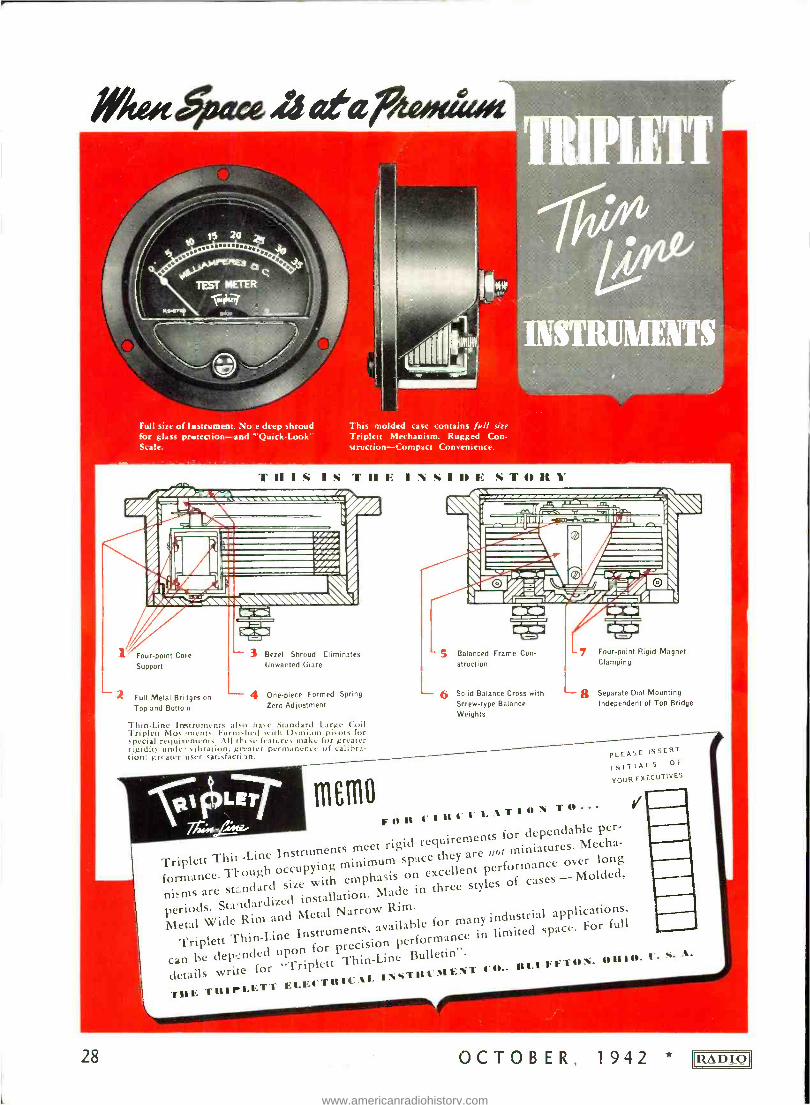
Full size of Instrument. No e deep shroud for glass protection--and "QuickLook' Scale.
This molded case contains lull size Triplett Mechanism. Rugged Con. structiun-- t.umpact Convenience.
TIIIPLETT
"rfrbrA4 bk#
13I Rili l W KJ
THIS IS THE INSIDE ST411t1' ---- -1A
106 e 1\\\\\\\\% \\ ,
1í__L -= Inr:--l -- ` ¡a%:i`--- t %_ /-.
1 Four -point Cote
Support
3 Bezel Shroud Eliminates Unwanted Glare
-2 Full Metal Briiges on -- 4 One -piece Formed Spring
Zero Adjustment Top and Bottom
S Balanced Frame Con-
struction
7 Four -point Rigid Magnet
Clamping
6 Solid Balance Cross with Screw -type Balance Weights
i8 Separate Dial Mounting Independent of Top Bridge
Thin -Line Instruments also have Standard Large Coil Triplett Mov sments. Furni-hed with Osmium piwuts for special requirements. All tFese features make for greater rigidity unde- vibration; greater permanence of calibra- tion; greater user satisfacti in.
ß; 1;r .441í'i `oll 1 IitCI.LATI0N TO... If
requirements for dependable per -
minimum space they are not miniatures. Mecha-
nisms
Tl i Instruments meet rigid space
performance over long nisms e. Thndar occupying
with emphasis on excellent p Molded, perioare
Standardized
size with eofp in three styles of cases -
periods. Standardized installation. applications,
Metal Wide Rim and Metal Narrow vRla le for many industrial app
Triplett Thin-Line epon for precision performance in limited space. For full
can be write
n "Triplett lett Thin -Line Bulletin ".
details write for P
'rill; TI[IrLFTT ELECTRICAL INSTRUMENT
C0- I 1[FFTIN, 1[[10-
PLEASE INSERT
INITIALS OF
YOUR EXECUTIVES
28 OCTOBER, 1942 * iZADIO
www.americanradiohistory.com
IN N a rM Portabl
e 2-Way F. M
M otprpla Mpbile
and Cpm/nv n/cation
.cyst ens
A.M. anc
1.1 Er, /et . ,e ncy
for Our Arnie( Irces
Corn/too
on yS anis
DESIGNED CIALVIN
IRADIOI
Radio Communication Systems AND ENGINEERED TO FIT SPECIAL NEEDS
nñ trOttrCifiATION CHICAGO
* OCTOBER, 1942 T7
www.americanradiohistory.com
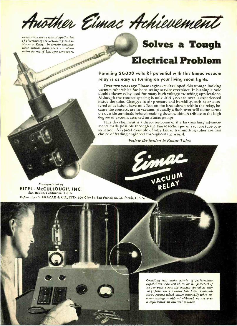
40W, a ez Illestratioa shows typical applica ion of electromagnet actuating coal to Vcunm Relay. In certain insta lla- tiois outside flash -ovens are elEmi- nated by use of ball type connec'ors.
Solves a Tough Electrical Problem
Handling 20,000 volts RF potential with this Eimac vacuum relay is as easy as turning on your living room lights.
Over two years ago Eimac engineers developed this strange looking vacuum tube which has been seeing service ever since. It is a single pole double throw relay used for many high voltage switching applications. Although the contact sparing is only .015 ", no arc -over is experienced inside the tube. Changes in air pressure and humidity, such as encoun- tered in aviation, have no effect on the breakdown within the relay, be- cause the contacts are in vacuum. Actually a flash -over will occur across the outside terminals before breaking down within. A tribute to the high degree of vacuum attained on Eimac pumps.
This development is a direct outcome of the far- reaching advance- ments made possible through the Eiinac technique of vacuum tube con- struction. A typical example of why Eimac transmitting tubes are first choice of leading engineers throughout the world.
Follow the leaders to Eimac Tubes
Manufactured by
EITEL- McCULLOUGH, INC. San Bruno, California, U. S. A.
Export Agents: FRAZAR & CO., LTD., 301 Clay St., San Francisco, California, U. S. A.
Gruelling tests make certain of performance capahil :ties. This test places an RF potential of 20,000 volts across the contacts spaced at only .015' from the grounded pole piece. Close -up shows cyrona which occurs externally when ex- treme soltage is applied although no arc -over is experienced on internal contacts.
www.americanradiohistory.com
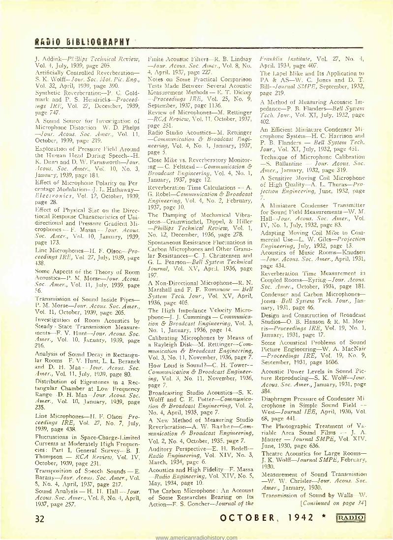
Rfai0 BIBLIOGRAPHY
J. Addink- Plillips Technical Review, Vol. 4, July, 1939, page 205. Artificially Controlled Reverberation- s. K. Wolff -Jour. Soc. 9Iot. Pic. Eng., Vol. 32, April, 1939, page 390. Synthetic Reverberation -P. C. Gold - mark and P. S. Hendricks- Proceed- ings IRE, Vol. 27, December, 1939, page 747.
A Sound Source for Investigation of Microphone Distortion -W. D. Phelps -Jour. Acous. Soc. Amer., Vol. 11, October, 1939, page 219.
Exploration of Pressure Field Around the Human Head During Speech -H. K. Dunn and D. W. Farnsworth -Jour. Acous. Soc. Amer., Vol. 10, No. 3, January, 1939, page 184. Effect of Microphone Polarity on Per- centage Modulation -J. L. Hathaway - Electronics, Vol. 12, October, 1939, page 28. Effect of Physical Size on the Direc- tional Response Characteristics of Uni- directional and Pressure Gradient Mi- crophones - F. Massa - Jour. Acous. Soc. Amer., Vol. 10, January, 1939, page 173.
Line Microphones -H. F. Olson -Pro- ceedings IRE, Vol. 27, July, 1939, page 438.
Some Aspects of the Theory of Room Acoustics -P. M. Morse -Jour. Acous. Soc. Amer., Vol. 11, July, 1939, page 56.
Transmission of Sound Inside Pipes - P. M. Morse -Jour. Acous. Soc. Amer., Vol. 11, October, 1939, page 205. Investigation of Room Acoustics by Steady - State Transmission Measure - ments-F. V. Hunt -Jour. Acous. Soc. Amer., Vol. 10, January, 1939, page 216.
Analysis of Sound Decay in Rectangu- lar Rooms -F. V. Hunt, L. L. Beranek and D. H. Maa - Jour. Acous. Soc. Amer., Vol. 11, July, 1939, page 80. Distribution of Eigentones in a Rec- tangular Chamber at Low Frequency Range -D. H. Maa -Jour. Acous. Soc. Amer., Vol. 10, January, 1939, page 235.
Line Microphones -H. F. Olson -Pro- ceedings IRE, Vol. 27, No. 7, July, 1939, page 438. Fluctuations in Space- Charge -Limited Currents at Moderately High Frequen- cies : Part I, General Survey -B. J. Thompson - RCA Review, Vol. IV, October, 1939, page 231. Transposition of Speech Sounds - E. Barany -Jour. Acous. Soc. Amer., Vol. 8, No. 4, April, 1937, page 217. Sound Analysis - H. H. Hall - Jour. Acous. Soc. Amer., Vol. 8, No. 4, April, 1937, page 257.
32
Finite Acoustic Filters -R. B. Lindsay -Jour. Acous. Soc. Amer., Vol. 8, No. 4, April, 1937, page 227. Notes on Some Practical Comparison Tests Made Between Several Acoustic Measurement Methods - E. T. Dickey -Proceedings IRE, Vol. 25, No. 9, September, 1937, page 1136. Review of Microphones -M. Rettinger -RCA Review, Vol. II, October, 1937, page 251. Radio Studio Acoustics -M. Rettinger -Communication & Broadcast Engi- neering, Vol. 4, No. 1, January, 1937, page 5.
Close -Mike vs. Reverberatory Monitor- ing - C. Felstead - Communication & Broadcast Engineering, Vol. 4, No. 1,
January, 1937, page 12.
Reverberation -Time Calculations - A. G. Robel- Communication & Broadcast Engineering, Vol. 4, No. 2, February, 1937, page 10.
The Damping of Mechanical Vibra- tions- Crainwinchel, Dippel, & Hiller -Phillips Technical Review, Vol. 1,
No. 12, December, 1936, page 278.
Spontaneous Resistance Fluctuations in Carbon Microphones and Other Granu- lar Resistances -C. J. Christensen and G. L. Pearson -Bell System Technical Journal, Vol. XV, April, 1936, page 197.
A Non -Directional Microphone -R. N. Marshall and F. F. Romanow - Bell System Tech. Jour., Vol. XV, April, 1936, page 405.
The High Impedance Velocity Micro - phone-J. J. Cummings - Communica- tion & Broadcast Engineering, Vol. 3, No. 1, January, 1936, page 14.
Calibrating Microphones by Means of a Rayleigh Disk -M. Rettinger -Com- munication & Broadcast Engineering, Vol. 3, No. 11, November, 1936, page 7.
How Loud is Sound ? -C. H. Tower - Communication & Broadcast Engineer- ing, Vol. 3, No. 11, November, 1936, page 7.
Broadcasting Studio Acoustics -S. K. Wolff and C. E. Potter- Communica- tion & Broadcast Engineering, Vol. 2,
No. 4, April, 1935, page 7.
A New Method of Measuring Studio Reverberation -A. W. Barber -Com- munication & Broadcast Engineering, Vol. 2, No. 4, October, 1935, page 7.
Auditory Perspective -E. H. Bedell - Radio Engineering, Vol. XIV, No. 3,
March, 1934, page 6.
Acoustics and High Fidelity -F. Massa -Radio Engineering, Vol. XIV, No. 5,
May, 1934, page 10.
The Carbon Microphone : An Account of Some Researches Bearing on Its Action -F. S. Goncher - Journal of the
Franklin Institute, Vol. 27, No. 4, April, 1934, page 407.
The Lapel Mike and Its Application to PA & AS -W. C. Jones and D. T. Bill- Journal SMPE, September, 1932, page 219.
A Method of Measuring Acoustic Im- pedance-P. B. Flanders -Bell System Tech. Jour., Vol. XI, July, 1932, page 402.
An Efficient Miniature Condenser Mi- crophone System -H. C. Harrison and P. B. Flanders - Bell System Tech. Jour., Vol. XI, July, 1932, page 451.
Technique of Microphone Calibration -S. Ballantine - Jour. Acous. Soc. Amer., January, 1932, page 319.
A Sensitive Moving Coil Microphone of High Quality -A. L. Thuras -Pro- jection Engineering, June, 1932, page 7.
A Miniature Condenser Transmitter for Sound Field Measurements -W. M. Hall -Jour. Acous. Soc. Amer., Vol. IV, No. 1, July, 1932, page 83.
Adapting Moving Coil Mike to Com- mercial Use -L. W. Giles- Projection Engineering, July, 1932, page 13. Acoustics of Music Rooms -Knudsen -Jour. Acous. Soc. Amer., April, 1931, page 434.
Reverberation Time Measurement in Coupled Rooms -Eyring -Jour. Acous. Soc. Amer., October, 1931, page 181.
Condenser and Carbon Microphones - Jones -Bell System Tech. Jour., Jan- uary, 1931, page 46.
Design and Construction of Broadcast Studios -O. B. Hanson & R. M. Mor- ris- Proceedings IRE, Vol. 19, No. 1,
January, 1931, page 17.
Some Acoustical Problems of Sound Picture Engineering -W. A. MacNair -Proceedings IRE, Vol. 19, No. 9, September, 1931, page 1606.
Acoustic Power Levels in Sound Pic- ture Reproducing -S. K. Wolff -Jour. Acous. Soc. Amer., January, 1931, page 384.
Diaphragm Pressure of Condenser Mi- crophone in Simple Sound Field - West-Journal IEE, April, 1930, Vol. 68, page 441.
The Photographic Treatment of Va- riable Area Sound Films - J. A. Maurer - Journal SMPE, Vol. XIV, June, 1930, page 636.
Theatre Acoustics for Large Rooms - J. K. Wolff- Journal SMPE, February, 1930.
Measurement of Sound Transmission -W. W. Chrisler -Jour. Acous. Soc. Amer., January, 1930.
Transmission of Sound by Walls --W. [Continued on page 34]
OCTOBER, 1942 * IIRAD1O
www.americanradiohistory.com
SEE FOR YOURSELF - why Simpson
Instruments STAY Accurate
THE service you get out of an electrical instrument depends entirely on the lasting accuracy that
is built into it. And, by the same token, the lasting accuracy of an
instrument depends entirely upon the stamina and accuracy inherent in the movement proper, for this is the very heart of every instrument.
In every Simpson Instrument you will find a move- ment like the one pictured above-a full bridge type movement with soft iron pole pieces. Men who know instruments have long recognized the basic superior- ity of this design. It not only permits a higher degree of accuracy -it assures maintained accuracy, year after year.
If your need for instruments is vital enough to give you the right to buy, it is vital enough to rate the best. Examine the Simpson movement, and you will see for yourself, why, to so many discriminating buyers, best means . . . Simpson.
SIMPSON ELECTRIC COMPANY 5212 Kinzie Street, Chicago, Illinois
rRADIO * OCTOBER, 1942
MODEL 260 High Sensitivity
Tester Here is a typical example of Simpson leadership Ranges to 5000 Volts, both AC and DC, at 20,000 ohms per volt DC and 1000 ohms per volt AC. Current readings from 1 microampere to 500 milli- amperes. Resistance read- ings from 1/2 ohm to 10 meg- ohms. Five decibel ranges, -10 to +52 DB.
33
www.americanradiohistory.com
RADIO BIBLIOGRAPHY
A. Sabine -Jour. Acous. Soc. Amer., January, 1930.
Reverberation Time in Dead Rooms - E. Eyring -Jour. Acous. Soc. Amer., January, 1930.
Optimum Reverberation Time for Au- ditoriums - W. A. MacNair - Jour. Acous. Soc. Amer., January, 1930. Methods of Noise Measurement -H. H. Free -Jour. Acous. Soc. Amer., July, 1930, page 18.
Result of Noise Surveys -G. C. Galt - Jour. Acous. Soc. Amer., July, 1930, page 30. Measurement and Calculation of Sound Insulation - W. L. Knudsen - Jour. Acous. Soc. Amer., July, 1930, page 129. Hearing of Speech in Auditoriums - W. L. Knudsen -Jour. Acous. Soc. Amer., October, 1929, page 58. Acoustic Considerations Involved in Steady State Loud Speaker Measure - ments-L. G. Bostwick - Bell System Tech. Jour., Vol. VIII, 1929, page 135. Articulation Testing Methods - H. Fletcher, and J. C. Steinberg -Bell System Tech. Jour., Vol. VIII, page 806.
Speech Power and Its Measurements - L. J. Sivian - Bell System Tech. Jour., Vol. VIII, 1929, page 576. A Measurement of Sound Pressure on an Obstacle - West - Journal IEE, 1929, Vol. 67, page 1137. An Introduction to "Speech and Hear - ing"-H. D. Arnold -Bell Lab. Rec- ord, Vol. VII, No. 6, February, 1929, page 217.
On the Acoustics of Large Rooms - L. V. Strutt -Phil. Mag., August, 1929.
Note on Theory of Acoustic Wave Filters -B. B. Lindsay Physical Re- view, August 15, 1929.
Acoustic Filters -W. P. Mason -Bell Lab. Record, Vol. VI, No. 6, August, 1928, page 392.
Use of Wente Condenser Transmitter to Measure Sound Pressure -Aldridge -Post Office Elec. Eng., July, 1928, Vol. 21, page 223.
Effect of Diffraction Around Micro- phone in Sound Measurement -S. Bal - lantine - Physical Review, Vol. 32, 1928, page 988.
Fundamentals of Speech, Hearing and Music - J. C. Steinberg-Bell Lab. Record, Vol. VIII, No. 3, November, 1928, page 75.
Speech Interpretation in Auditoriums -E. C. Wente -Bell Lab. Record, Vol. VII, No. 2, October, 1928, page 47.
The Quality of Speech and Music - J. C. Steinberg -Journal SMPE, Vol.
34
XII, No. 35, September, 1928, page 633.
The Physical Characteristics of Music and Speech - D. C. Miller - Journal SMPE, Vol. XII, No. 35, Sept., 1928. page 647. A System of Motion Pictures with Sound -H. B. Marvin - Journal SMPE, Vol. XII, No. 33, April, 1928, page 86. Ideal Auditorium Acoustics -K. Wat- son- Journal American Institute Ar- chitects, July, 1928.
Measuring of Acoustic Impedance and the Absorption Coefficient of Porous Materials -E. C. Wente and E. H. Be- dell -Bell System Tech. Jour., Vol. VII, 1928, page 1.
Some Acoustical Phenomena- Davis- Proceedings Physical Society of Lon- don, April, 1928.
Propagation Characteristics of Sound Tubes -W. P. Mason - Physical Re- view, February, 1928.
Acoustic Wave Filters and Audio -Fre- quency Selectivity - R. B. Bourne - QST, Vol. 12, August, 1928, page 23.
Current Analysis in Constant Resist- ance Modulation - L. A. Grandy - Journal AIF_E, May, 1927.
Dynamical Study of the Vowel Sounds -I. B. Crandall -Bell System Tech. Jour., Vol. VI, 1927, page 100.
Study of the Regular Combination of Acoustic Elements, with Application to Recurrent Acoustic Filters, Tapered Acoustic Filters, and Horns - W. P. Mason -Bell System Tech. Jour., Vol. VI, 1927, page 258. The Loudness of Pure Tones -B. A. Kingsbury -Bell Lab. Record, Vol. III. No. 6, February, 1927, page 188.
Auditory Masking -C. E. Lane -Bell I.ab. Record, Vol. TT, May 3, 1936, No. 3, page 96.
Sound - T. C. Steinberg -Bell Lab. Record, Vol. TT, No. 6, August, 1926. page 235.
Speech Sounds -J. B. Kelly -Bell Lab. Record, Vol. IT, No. 5, July, 1926, page 216.
Acoustic Wave Filter Theory -Stew- art- Physical Research, June, 1923. Variable Sinrrle Band Wave Filter - Stewart - Physical Research, Novem- ber, 1923.
Predicted Transmission Curves of Acoustic Filters - Peacock - Physical Review, February, 1923.
The Engineering Design of Submarine Acoustic Signaling Apparatus - W. Hahnemann -Proceedings IRE, Febru- ary, 1923, page O.
Acoustics of Rooms - H. Eckhardt - Journal Franklin Institute, June, 1923.
Diaphragmless Microphone for Broad- casting - Thomas - Journal AIEE, August, 1923.
The Physical Characteristics of Audi- tion and Dynamical Analysis of the External Ear -R. L. Wegel and H. Fletcher - Bell System Tech. Jour., Vol. 1, No. 2, 1922, page 56. Analysis of the Energy Distribution in Speech -I. B. Crandall & D. Crandall & D. MacKenzie -Bell System Tech. Jour., Vol. 1, No. 1, 1922, page 116.
Dynamical Analysis of the External Ear -R. L. Wegel -Bell System Tech. lour., Vol. 1, No. 2, 1922, page 56.
The Nature of Speech and Its Inter- pretation - H. Fletcher - Bell System Tech. Jour.. Vol. 1, No. 1, 1922, page 129.
Acoustic Wave Filters -G. W. Stewart -Physical Review, December, 1922. An Acoustic Wave Filter - G. W. Stewart - Physical Review, March. 1921.
Condenser Transmitter -E. C. Wente -Physical Review, July, 1917..
LOUDSPEAKERS
Hypex Horns -F. Salmon- Electron- ics, Vol. XIV, July, 1941, page 34. Loudspeaker Dividing Networks -J. K. Hilliard- Electronics, Vol. XIV, Janu- ary, 1941, page 26.
Acoustic Line Loudspeakers -W. D. Phelps -Electronics, Vol. XIII, March. 1940, page 30.
Coaxial Loudspeaker - B. Olney - Electronic.c, Vol. XIII, April, 1940. page 32.
27 -Inch Loudspeaker at New York World's Fair -R. T. Bozak- Electron- ics, Vol. XIII, June, 1940, page 22.
Vented Speaker Enclosure - E. C. Holkstra - Electronics, Vol. XIII, March, 1940, page 34.
Production of the Modern Loudspeaker - H. Golden - Communications, Vol. 20, No. 3, March, 1940, page 15. A Noise -Free Radio Receiver -G. W. Eyler and J. A. Worcester, Jr. -Gen- eral Electric Review, Vol. 42, July, 1939, page 309. Non -Linear Distortion Electrodynamic Loudspeaker -V. V. Furdeev, N. K. Mikheeva and G. S. Grigor'ev-Ixves- ti,ga Elektro -Prom. Slab. Tlka. 1939, page 25. Light Coil Twin Loudspeaker -Voigh - Wireless World. Vol. 44, March, 1939, page 223. Tnhomogeneity of the Magnetic Fields of Dynamic Loudspeakers -W. Rein- hard - Akust. Zeit., Vol. 4, March, 1939, page 137.
OCTOBER, 1942 RADIO
www.americanradiohistory.com
RADIO BIBLIOGRAPHY
Output Stage Distortion -A. J. Heins van der Ven.- Wireless Engineer, Vol. 16, August, 1939, page 383. Wireless Engineer, Vol. 16, September, 1939, page 444. The Sound Spectra of Sparks and Pis- tol Shots with Reference to Their Ap- plication to Electroacoustic Measure- ment Technique, Akust. Zeit., Vol. 4, November, 1939, page 373. Multiple Coil, Multiple Cone Loud- speakers - H. F. Olsen -lour. Acous. Soc. Amer., Vol. 10, April, 1939, page 305.
Horn-Type Loudspeakers -F. Massa - Proceedings IRE, Vol. 26, No. 6, June, 1938, page 720. The Impedance of the Voice Coil of a Loudspeaker - J. B. Rudd - AWA Tech. Review (Australia), Vol. 3, No. 3, January, 1938, page 100. Horn Loudspeakers - H. F. Olsen - RCA Review, Vol. I, April, 1937, page 68.
Efficiency and Distortion in Horn Loudspeakers -H. F. Olsen -RCA Re- view, Vol. II, October, 1937, page 265. Sound Reinforcing Systems - H. F. Olsen -RCA Review, Vol. I, July, 1936, page 49. Improving Low Frequency Response - R. D. Rettenmeyer -Radio Engineer- ing, Vol. XVI, No. 6, June 6, 1936, page 14.
Speaker Design -J. Q. Tiedge -Radio Engineering, Vol. XVI, No. 1, January, 1936, page 11.
The Magic Voice -C. O. Caulton, E. T. Dickey and S. V. Perry -Radio En- gineering, Vol. XVI, No. 10, October, 1936, page 8. Nipermag Speaker, Radio Engineering, Vol. XVI, No. 3, March, 1936, page 20. Theory of Loudspeakers and Mechani- cal Oscillatory Systems -H. Roder - Radio Engineering, Vol. XVI, No. 7, July, 1936, page 10.
The Design of Exponential Horns - W. S. Duncan - Communication and Broadcast Engineering, Vol. 3, No. 11, November, 1936, page 8. Piezoelectric Loudspeakers - A. L. Williams -Journal SMPE, Vol. XXIV, No. 2, February, 1935, page 121. A Common Defect in Cone Loud- speakers - (Editorial), Wireless En- gineer, Vol. XIII, No. 144, September. 1935, page 469. Electro-Acoustical Problems - C. N. Smith- Wireless Engineer, Vol. XII, No. 145, October, 1935, page 543. Effect of Cone Type Moving Coil Loudspeaker -H. Wada -Journal IEE of Japan, Vol. 54, No. 548, March, 1934, page 20.
ADIO * OCTOBER
On the Amplitude of Loudspeaker Dia- phragm of Low Frequency-N. W. McLachlan - Experimental Wireless and Wireless Engineer, Vol. X, No. 119, August, 1933, page 420.
Comments on Theory of Horns -Hall -Jour. Acous. Soc. Amer., Vol. III, No. 4, April, 1932, page 552. Mathematical Theory of Vibrating Membranes and Plates - Colwell & Stewart - Jour,. Acous. Soc. Amer., Vol. III, No. 4, April, 1932, page 591. Estimating Room Error in Loudspeak- er Tests -E. W. Kellogg -Jour. Acous. Soc. Amer., Vol. IV, No. 1, July, 1932, page 56.
Condenser Loudspeaker with Flexible Electrodes -P. E. Edelman- Proceed- ings IRE, Vol. 19, No. 2, February, 1931, page 256. On the Amplitude of Driven Loud- speaker Cones -M. J. O. Strutt -Pro- ceedings IRE, Vol. 19, No. 5, May, 1931, page 839.
Notes on Loudspeaker Response Meas- urements and Some Typical Response Curves -B. Olney-Proceedings IRE, Vol. 19, No. 7, July, 1931, page 1113.
Magnetic Characteristic Design -Urhl- ing -Radio Broadcast, March, 1930, page 265.
Loudspeakers for Use in Theatres -D. G. Blattner - Journal SMPE, February, 1930.
Directional Characteristics of Loud- speakers - Matter - Electronics, July, 1930, page 186.
Electrodynamic Reproducers -Batcher -Radio News, August, 1930, page 111.
Flat Piston Moving Coil Loudspeaker -Paul and Cohen- Experimental Wireless and Wireless Engineer, Sep- tember, 1930, page 47.
Magnetic Damping of the Moving Coil -McLachlan - Wireless World, March 5, 1930.
Loudspeaker Tests and Performance Factors -Oliver -Experimental Wire- less and Wireless Engineer, December, 1930, page 653.
Acoustic Considerations Involved in Steady State Loudspeaker Measure- ments- Bostwic k- Bell System Tech. Jour., Vol. VIII, 1929, page 135. What's a Good Loudspeaker - L. G. Bostwick -Bell. Lab. Record, Vol. VII, No. 9, May, 1929, page 457.
Sound Radiation from a System of Vi- brating Circular Diaphragms - S. K. Wolff- Physical Review, June, 1929.
Inductor Dynamic Loudspeakers - Dreisbach -Radio Broadcasting, June, 1929, page 94.
Kyle Condenser Loudspeaker - Grea-
1942
vers and Kranz - Proceedings IRE, July, 1929, page 114.
Some Aspects of Loudspeaker Devel- opment - I. Woolf - Motion Picture Proj., September - October - November, 1931.
Measurement of Loudspeaker in Vac- uums - Turner - Experimental Wire- less and Wireless Engineer, March, 1931, page 129.
Permanent Magnets for Electronic In- struments -Hoppe - Electronics, May, 1931, page 636.
The Inductor Dynamic Loudspeaker - Oliver - Wireless World, November, 1931, page 579. Acoustic Apparatus for Reproduction Approach and Music - McLachlan - Phil. Mag., January, 1931, page 2.
Production of Acoustic Waves by Air Jet- Hartmann -Phil Mag. and Jour- nal of Sci., April, 1931, page 926.
The Condenser Type Loudspeaker - Morgan - Radio Broadcast, March, 1929, page 369.
The Twenty -Four Inch Cone -G. R. Lum -Bell Lab. Record, Vol. V, No. 6, February, 1928, page 201.
An Efficient Driving Coil for Loud- speakers - A. L. Thuras - Bell Lab. Record, Vol. VI, No. 6, August, 1928, page 409.
High Efficiency Receiver of Large Power Capacity for Horn -Type Loud- speakers - E. C. Wente and A. L. Thuras -Bell System Tech. Jour., Vol. VII, 1928, page 140.
Measuring Acoustics -E. C. Wente and H. Bedell -Bell System Tech. Jour., January, 1928.
High Efficiency Receivers - E. C. Wente and A. L. Thuras -Bell System Tech. Jour., January, 1928.
Sound Measurement and Loudspeaker Characterists - S. K. Wolff - Pro- ceedings IRE, December, 1928.
Loudspeaker Diaphragm-L. A. Mc- Lachlan- Wireless World, March 23, 1937.
Fundamental Analysis of Loudspeakers -- S. F. Nielssen - Proceedings IRE, February, 1927.
Loudspeaker Test Methods -I. Wolf and H. Ringle - Proceedings IRE, May, 1927.
Development of New Type Loudspeak- er-C. W. Rice and W. M. Kellogg - Journal AIEE, September, 1925.
Note on Telephone Receiver Imped- ance-E. Z. Stowell- Proceedings IRE, April, 1925, page 245.
[Continued on page 39]
35
www.americanradiohistory.com
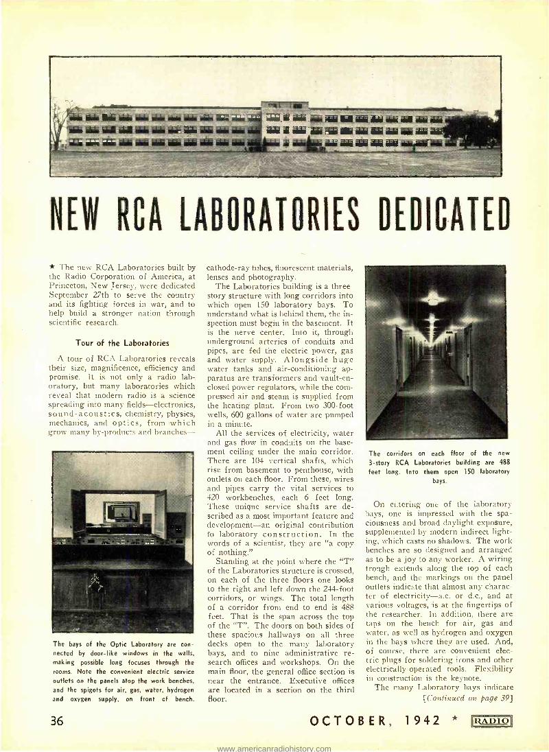
tuia ai s mini- rQww Mela .ieia
4:6 sigis sadr 44. iáaier silis .ie r r.L addr
Aim 1611 466 íriir Tri .iati aair rüí gal iis 46au.íííSU AI
aaa ais au
NEW RCA LABORATORIES DEDICATED
* The new RCA Laboratories built by the Radio Corporation of America, at Princeton, New Jersey. were dedicated September 27th to serve the country and its fighting forces in war, and to help build a stronger nation through scientific research.
Tour of the Laboratories
A tour of RCA Laboratories reveals their size, magnificence, efficiency and promise. It is not only a radio lab -. oratory, but many laboratories which reveal that modern radio is a science spreading into many fields -electronics, sound- acoustics, chemistry, physics, mechanics, and optics, from which
rmv many hy- products and branches-
The bays of the Optic Laboratory are con- nected by door -like windows in the walls, making possible long focuses through the rooms. Note the convenient electric service outlets on the panels atop the work benches,
and the spigots for air, gas, water, hydrogen
and oxygen supply, on front of bench.
36
cathode -ray tubes, fluorescent materials, lenses and photography.
The Laboratories building is a three - story structure with long corridors into which open 150 laboratory bays. To understand what is behind them, the in- spection must begin in the basement. It is the nerve center. Into it, through underground arteries of conduits and pipes, are fed the electric power, gas and water supply. Alongside huge water tanks and air -conditioning ap- paratus are transformers and vault -en- closed power regulators, while the com- pressed air and steam is supplied from the heating plant. From two 300 -foot wells, 600 gallons of water are pumped in a minute.
All the services of electricity, water and gas flow in conduits on the base- ment ceiling under the main corridor. There are 104 vertical shafts, which rise from basement to penthouse, with outlets on each floor. From these, wires and pipes carry the vital services to 420 workbenches, each 6 feet long. These unique service shafts are de- scribed as a most important feature and development -an original contribution to laboratory construction. In the words of a scientist, they are "a copy of nothing."
Standing at the point where the "T" of the Laboratories structure is crossed, on each of the three floors one looks to the right and left down the 244 -foot corridors, or wings. The total length of a corridor from end to end is 488 feet. That is the span across the top of the "T ". The doors on both sides of these spacious hallways on all three decks open to the many laboratory bays, and to nine administrative re- search offices and workshops. On the main floor, the general office section is near the entrance. Executive offices are located in a section on the third floor.
OCTOB
The corridors on each floor of the new
3 -story RCA Laboratories building are 488
feet long. Into them open 150 laboratory
bays.
On entering one of the laboratory bays, one is impressed with the spa- ciousness and broad daylight exposure, supplemented by modern indirect light- ing, which casts no shadows. The work benches are so designed and arranged as to be a joy to any worker. A wiring trough extends along the top of each bench, and the markings on the panel outlets indicate that almost any charac- ter of electricity -a.c. or d.c., and at various voltages, is at the fingertips of the researcher. In addition, there are taps on the bench for air, gas and water, as well as hydrogen and oxygen in the bays where they are used. And, of course, there are convenient elec- tric plugs for soldering irons and other electrically- operated tools. Flexibility in construction is the keynote.
The many Laboratory bays indicate [Continued on page 39]
ER, 1942 * IRADIOI
www.americanradiohistory.com
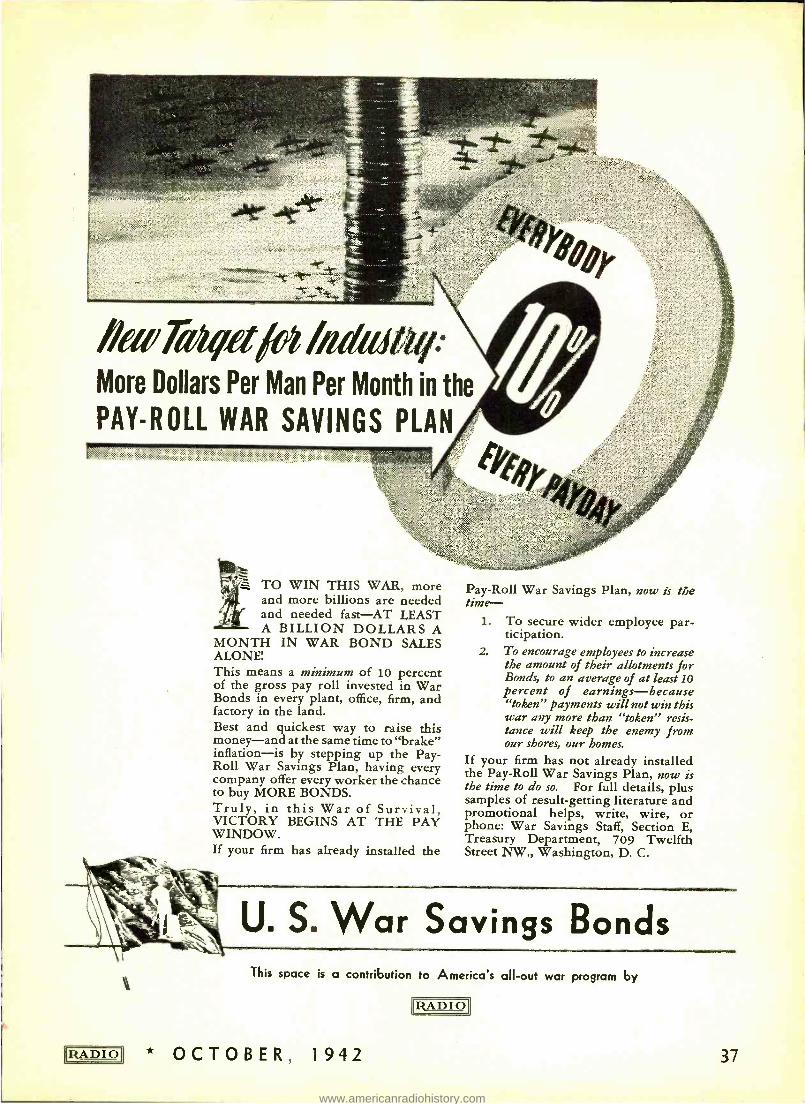
oat -Ar
ñeeTail/o fiai alliqo' More Dollars Per Man Per Month in the
PAY -ROLL WAR SAVINGS PLAN v:. ..: :.:,::;:: ::, ::::::..::::: ::.t:.:::.:a: -:::.::::: ;:::::
... : .:::.::.. :. ï: .::. ::. ::.:::.:. .. .:: ..::.::. ::.:.:::::.... . .:..r .: :::.:.:::: . r .:. .. :.::.. :v .:.:.::: .: :...t.1:,.,::::::.:A::..::*:ï::::::::.:::::::::::::. :::: :::::::::::.::::::
TO WIN THIS WAR, more and more billions are needed and needed fast -AT LEAST A BILLION DOLLARS A
MONTH IN WAR BOND SALES ALONE' This means a minimum of 10 percent of the gross pay roll invested in War Bonds in every plant, office, firm, and factory in the land. Best and quickest way to raise this money -and at the same time to "brake" inflation -is by stepping up the Pay - Roll War Savings Plan, having every company offer every worker the chance to buy MORE BONDS. Truly, in this War of Survival, VICTORY BEGINS AT THE PAY WINDOW. If your firm has already installed the
IRA DIOI
Pay -Roll War Savings Plan, now is the time -
1. To secure wider employee par- ticipation.
2. To encourage employees to increase the amount of their allotments for Bonds, to an average of at least 10 percent of earnings- because "token" payments will not win this war any more than "token" resis- tance will keep the enemy from our shores, our homes.
If your firm has not already installed the Pay -Roll War Savings Plan, now is the time to do so. For full details, plus samples of result -getting literature and promotional helps, write, wire, or phone: War Savings Staff, Section E, Treasury Department, 709 Twelfth Street NW., Washington, D. C.
U. S. War Savings Bonds This space is a contribution to America's all -out war program by
RADIO
* OCTOBER, 1942 37
www.americanradiohistory.com
ARMY -NAVY TUBE LIST
[Continued from page 11]
mentioned in Paragraph 2 above, is taken to include:
a. Equipments basically new in elec- trical design, with no similar pro- totypes.
b. Equipments having a similar pro- totype but completely redesigned as to electrical characteristics.
c. New test equipment for opera- tional field use.
4. The term "new equipments ", as
mentioned in Paragraph 2 above, does not include:
a. Equipments either basically new or redesigned, that are likely to be manufactured in very small quantity, such as laboratory measuring instruments.
b. Equipments that are solely me- chanical redesigns of existing pro- totypes.
c. Equipments that are reorders without change of existing models.
d. Equipments in the design stage before the effective date of adop- tion of this Preferred List.
MICA CAPACITORS "Quality Above All" mica capacitors add reliability to the communications equipment used by the Armed Service Branches of our Government. This self -same dependability is available to you t Standardize on Solar micas -as well as dry, wet and paper capa- citors -for satisfactory, uninterrupted service.
Special Catalog 12 -E Available On Letterhead Request
38
Note: The foregoing statements in Paragraphs 3 and 4 above are explanatory in nature and are not intended to be all- inclusive.
5. In the event that it is believed that an unclassified tube other than these included in the Preferred List should be used in the design of new equipments for either the Signal Corps or Navy, specific approval of the Serv- ice concerned must be obtained. Such approval, when Signal Corps equip- ment is concerned, is to be requested from the Signal Corps Laboratory con- cerned with such equipment ; the said Laboratory will then make known its recommendations in the matter to the Office of the Chief Signal Officer where the final decision will be made and re- turned to the laboratory for transmit- tal to the party requesting the excep- tion. When Navy equipment is con- cerned, the request for exception shall be addressed to the Bureau of Ships, Navy Department.
6. The publication of the attached Army -Navy Preferred List of Vacuum Tubes has no application to the use of vacuum tubes classified as to security status, or to tubes which have no functional counterparts in the pre- ferred list. The choice of vacuum tubes not covered by the preferred list is to be made with the approval of the Sig- nal Corps or the Bureau of Ships, for Signal Corps or Navy equipment re- spectively as outlined in Paragraph 5
above. 7. The publication of this list is in
no way intended to hamper or restrict development work in the field of vacuum tubes or vacuum tube applica- tions.
8. This list is to take effect im- mediately. September 28, 1942.
Office of the Chief Signal Officer, Headquarters, Services of Supply, War Department. Chief of the Bureau of Ships, Navy Department.
KMPC's GROUND SYSTEM
[Continued from page 16]
killed by spraying with Diesel oil. Each tower is individually surrounded by a 7 -foot high galvanized fence and again grounded to the individual ground systems.
Extending from the far tower to the transmitting building is a 6 -inch cop- per strip. This is connected to all ground wires and equipment, and fol- lows directly beneath the transmission line which is mounted on rollers to al- low for expansion and contraction. The transmission line is divided into three sections, the sections terminating
OCTOB ER, 1942 * RADIO
www.americanradiohistory.com
RADIO BIBLIOGRAPHY
The Band -Pass Filter -G. H. Brown- ing- Radio -April, 1929.
Practical Design of A. F. Filter -L. Tubbs -Radio, May, 1929.
Design of R. F. Band -Pass Filters -A. J. Hirsch -Radio Engineering, Septem- ber, 1929. Band -Pass Tuning -K. Farrar -Radio Engineering, July, 1929, page 27.
Notes on Design of R.F. Band -Pass Filters -A. J. Hirsch - Radio Engi- neering, September, 1929.
Corrosion of Lead Cable Sheath -R. M. Burns - Bell Lab. Record, Vol. VIII, No. 5, January, 1929, page 187.
Principles of Electric Circuits Applied to Communication -H. S. Osborne - Bell System Tech. Jour., Vol. VIII, 1929, page 3.
New Method for Obtaining Transient Solutions of Electrical Networks -W. P. Mason -Bell System Tech. Jour., Vol. VIII, 1929, page 109.
Distortion Correction in Electrical Cir- cuits with Constant Resistance Recur- rent Networks -C. J. Zobel -Bell Sys- tem Tech. Jour., Vol. VII, 1928, page 438.
Phase Distortion and Phase Distortion Correction -S. P. Mead -Bell System Tech. Jour., Vol. VII, 1928, page 195.
R.F. Amplifiers -L. Smith -Bell Sys- tem Tech. Jour., April, 1924.
High- Frequency Amplifiers -H. R. Friis and Y. Jensen - Bell System Tech. Jour., April, 1924.
Tuned R.F. Transformers -G. H. Browning and F. Drake - Proceedings IRE, December, 1925. Mechanical Filters -R. F. L. Hartley - Bell Lab. Record, Vol. IV, No. 2, April, 1927, page 266. Notes on Neutralized Receivers -L. A. Hazeltine -Proceedings IRE, July, 1926. Selectivity of T.R.F. Receivers -L. A. Hazeltine -Proceedings IRE, July, 1926.
Frequency Discrimination to R.F. Re- ceivers -L. A. Hazeltine- Proceedings IRE, July, 1926. Magnetic & Static Coupling-E. A. Loftin and S. V. White-Proceedings IRE, October, 1926. A Method for Maximization in Circuit Calculation -W. van B. Roberts -Pro- ceedings IRE, October, 1926, page 689. Regeneration in Coupled Circuits -E. L. Chaffee - Proceedings IRE, June, 1924. page 299. A Generalization of the Reciprocal Theorem -J. R. Carson -Bell System Tech. Jour., Vol. III, No. 3, 1924, page 393. Theorems Regarding the Driving -Point Impedance of Two -Mesh Circuits -R.
30
M. Foster -Bell System Tech. Jour., Vol. III, No. 4, 1924, page 651.
Transmission Characteristics of Elec- tric Wave Filters -O. J. Zobel -Bell System Tech. lour., Vol. III, No. 4, 1924, page 567. A Reactance Theorem -R. M. Foster -Bell System Tech. Jour., Vol. III, No. 2, 1924, page 259.
Impedance of Smooth Lines and De- sign of Simulating Networks -R. S. Hoyt -Bell System Tech. Jour., Vol. 2, No. 2, 1923, page 1.
Impedances of Grounded Circuits -G. A. Campbell -Bell System Tech. Jour., Vol. 2, No. 4, 1923, page 1.
Transient Oscillations in Electric Wave Filters -J. R. Carson and O. J. Zobel -Bell System Tech. Jour., Vol. 2, No. 5, 1923, page 1.
Theory and Design of Uniform and Composite Electric Wave Filters-O. J. Zobell - Bell System Tech. Jour., Vol. 2, No. 1, 1923, page 1.
Electric Wave Filter Theory -A. A. Campbell - Bell System Tech. Jour., Vol. 1, No. 2, 1922, page 1.
Frequencies and Damping Factors of Coupled Circuits -L. Cohen- Proceed- ings IRE, 1921, page 150.
On the Poulsen Arc in Coupled Cir- cuits - P. O. Pedersen - Proceedings IRE, June, 1921, page 228.
Electorstatically Coupled Circuits - L. Cohen -Proceedings IRE, October. 1920, page 434.
A Study of E''ectrostatically Coupled Circuits - W. O. Lytle - Proceedings IRE, August, 1919, page 427. Additional Notes on "The Coupled Cir- cuit by the Method of Generalized An- gular Velocities " -V. Bush- Proceed- ings IRE, Apri'_, 1918, page 111.
Theory of Free and Sustained Oscilla - tions-H. G. Cordes- Proceedings IRE, 1918, page 167.
Further Discussion on "The Coupled Circuit by the Method of Generalized Angular Velocities " -V. Bush & J. R. Carson -Proceedings IRE, December, 1917, page 447. The Coupled Circuit by the Method of Generalized Angular Velocities --V. Bush - Proceedings IRE, October, 1917, page 363.
The Effect of the Spark on the Oscil- lations of an Electric Circuit -J. S. Stone- Proceedings IRE, October, 1917, page 363.
Arc Oscillations in Coupled Circuits - H. Yagi - Proceedings IRE, August. 1916, page 371.
Amplitude Relations in Coupled Cir- cuits-E. L. Chaffee- Proceedings IRE, June, 1916, page 283.
Resonance Phenomena in the Low - Frequency Circuit of Radio Transmit - ters-H. E. Hallborg- Proceedings IRE, June, 1915, page 107.
ACOUSTICS & SOUND
Averaging DB Measurements -M. Ret- tinger- Communications, Vol. 21, No. 7, July, 1941, page 11.
Sound in the Theatre - H. Burris - Mayer -Jour. Acous. Soc. Amer., Vol. 11, January, 1940, page 346.
Statistical Measurements on Conversa- tional Speech -H. K. Dunn & S. D. White -Jour. Acous. Soc. Amer., Vol. 11, January, 1940, page 278.
6 -Way Terminal Microphones -W. R. Harry -Bell Lab. Record, Vol. 19, No. 1, September, 1940, page 10.
A Method for Producing Extremely Strong Standing Sound Waves in Air -K. Oberst -Jour. Acous. Soc. Amer., Vol. 12, No. 2, October, 1940, page 308.
Schallavwehr in Bau -und Maxchinen- wesen - E. Lubcke -Hoch: Tech. u. Elek. aus, Vol. 56, No. 2, August, 1940, page 64.
Elements of Acoustical Engineering - H. F. Olson -Jour. Acons. Soc. Amer., Vol. 12, No. 2, October, 1940, page 312.
A New Technique for Determining Ul- trasonic Velocities in Liquids - Nara - sinhauja and Doraiswamaya - Indian Journal of Physics, Vol. 14, No. 3,
June, 1940, page 187.
Normal Modes of Vibration in Room Acoustics ; Experimental Investigations in Non -Rectangular Enclosures -R. H. Bolt -Jour. Acous. Soc. Amer., Vol. 11,
October, 1939, page 184.
Effect of an Absorbing Wall on the Decay of Normal Frequencies -N. B. Bhatt -Jour. Acous. Soc. Amer., Vol. 11, July, 1939, page 67.
Comparison of Sound Absorption Co- efficients Obtained by Different Meth - ods-F. J. Willig -Jour. Acons. Soc. Amer., Vol. 10, January, 1939, page 293. The Multitone -W. L. Barrow -Jour. Acous. Soc. Amer., Vol. 10, page 275, April, 1939. On Sound Absorption with the Aid of Damped Resonators - W. \ \'illms - Akust. Zeit., Vol. 4, January, 1939, page 29. Design and Properties of an Adjust- able Comparison Impedance -K. Schuster and W. Stohr -Akust. Zeit., Vol. 4, July, 1939, page 253. Communication from the German Acoustics Committee, Akust. Zeit., Vol. 4, January, 1939, page 62. The Pitch of Musical Instruments and Orchestras -B. Van der Pol and C. C.
[Continued on page 32]
OCTOBER, 1942 RADIO
www.americanradiohistory.com
RADIO BIBLIOGRAPHY
No. 5, May, 1937, page 620.
Constant Resistance Networks with Applications to Filter Groups -E. L. Norton -Bell System Tech. Jour., Vol. XVI, April, 1937, page 178.
The Use of Coaxial and Balanced Transmission Lines in Filters and Wide -Band Transformers for High Radio Frequencies -W. P. Mason and R. A. Sykes -Bell System Tech. Jour., Vol. XVI, July, 1937, page 275.
A Ladder Network Theorem -J. Rior- dan -Bell System Tech. Jour., Vol. XVI, July, 1937, page 303.
Resistance Compensated Band -Pass Crystal Filters for Use in Unbalanced Circuits -W. P. Mason-Bell System Tech. Jour., Vol. XVI, October, 1937, page 423.
Crystal Filter Design -W. W. Waltz - Radio Engineering, Vol. XVI, No. 1,
January, 1936, page 7.
Electrical Filters -B. van der Pol and T. J. Weigers- Philips Technical Re- view, Vol. 1, No. 9, September, 1936, page 270.
The Frequency Stability of Tuned Cir- cuits-J. H. Peddington- Wireless En- gineer, Vol. XIII, No. 153, June, 1936, page 302.
Fundamentals in the Application of Matrices to Electrical Networks -J. R. Pernice -Communications, August, 1936, page 12.
Design of Resistance Pads -C. F. Nor - dica- Communications, November, 1936, page 12.
Phase Shifting Networks -C. E. Smith - Communication & Broadcast Engi- neering, Vol. 3, No. 5, May, 1936, page 21.
Fundamentals in the Application of Matrices to Electrical Networks -J. R. Pernice- Communication & Broadcast Engineering, Vol. 3, No. 6, June, 1936, page 10.
Generalized Characteristics of Linear Networks -E. K. Sandeman -- Wireless Engineer, December, 1936, page 637.
The Design of Pads -L. W. Barnett - Communication & Broadcast Engineer - ing, Vol. 2, No. 2, February, 1935, page 12.
Program Circuit Equalizers - M. J. Oman -Communication & Broadcast Engineering, Vol. 2, No. 4, April, 1935, page 11.
Parallel Resonant Circuit- Communi- cation & Broadcast Engineering, Vol. 2, No. 11, November, 1935, page 18.
Broadcast Equalizers -R. Kenyon - Communication & Broadcast Engineer- ing, Vol. 2, No. 8, August, 1935, page 11.
Designing Resistor Attenuating Net-
works - P. K. McElroy - Proceedings IRE, Vol. 23, No. 3, March, 1935, page 213.
A Universal Network Chart, Elec- tronics, March, 1935, page 18.
The Design of Pads -L. W. Barnett - Communications, February, 1935, page 18.
Impedance Matching at Audio Fre- quencies-T. W. Kilmer- Communica- tions, September, 1935, page 18.
Short -Wave Design Calculations - R. R. Batcher -Radio News, Vol. XVI, No. 10, April, 1935, page 618.
Some Methods for Improving Res- onance Circuit Response and Im- pedance Calculation -H. T. Budenbom -Radio Engineering, Vol. XV, No. 8, August, 1935, page 7.
Crystal Filters for Radio Receivers - C. F. Nordica -Radio Engineering, Vol. XV, No. 11, November, 1935, page 9.
Calculating Series and Parallel Im- pedance - C. A. Mizen - Radio Engi- neering, Vol. XIV, No. 8, August, 1934, page 14.
Impedance Matching Networks -B. Ephraim -Radio Engineering, Vol. XIV, No. 10, October, 1934, page 12.
Chart for Simple Attenuator Design - W. W. Waltz - Electronics, August, 1934, page 247. The Design of Constant Resistance At- tenuators - R. S. Rangachare - Wire- less Engineer, Vol. XI, No. 134, No- vember, 1934, page 596. A Nomogram for the Band -Pass Fil - ter-A. T. Starr and H. C. Hall - Journal IEE, Vol. 75, No. 456, Decem- her, 1934, page 749. A General Theory of Electric Wave Filters -H. W. Bode -Jour. of Math. & Physics, Vol. XIII, No. 3, Novem- ber, 1934, page 275. An Improved I.F. Transformer Design -A. A. Webster -Radio News, June, 1933, page 740.
The Optimum Decrement of Tuned Circuits for Reception of Telephone Signals -D. A. Bell- Wireless Engi- neer, July, 1933, page 371.
Precision Methods Used in Construct- ing Electric Wave Filters for Carrier Systems - G. R. Harris - Bell System Tech. Jour., Vol. XI, April, 1932, page 264.
Electric Filter Design -J. K. Johnson -Radio News, June, 1932, page 1016.
New Theory and Design of Wave Fil - ters-W. Caner -Physics, Vol. 2, April, 1932, page 242.
Analysis and Design Characteristics of Resonant Circuits -M. Reed - Wireless
RADIO1 * OCTOBER, 1942
Engineer, Vol. IX, No. 104, May, 1932, page 259. A. F. Compensation Methods - J. G. Aceves- Electronics, December, 1932, page 224.
Simplified Inductance -K. Russel - Electronics, April, 1932, page 598.
Impedance - Matching Networks - W. Theessen - Electronics, March, 1931, page 552.
Design of Attenuation Networks - Lanteman- Electronics, February, 1931, page 508.
A System for Suppressing Hum by a New Filter Arrangement -P. H. Craig - Proceedings IRE, Vol. 19, No. 4, April, 1931, page 664.
Negative Circuit Constants -L. C. Ver - man- Proceedings IRE, Vol. 19, No. 4, April, 1932, page 676.
Theory and Operation of Tuned Radio - Frequency Coupling Systems -H. A. Wheeler and W. A. MacDonald -Pro- ceedings IRE, Vol. 19, No. 5, May, 1931, page 738.
Selectivity; a Simplified Mathematical Treatment -B. de F. Bayly- Proceed- ings IRE, Vol. 19, No. 5, May, 1931, page 873. Note on Radio- Frequency Transformer Coupled Circuit Theory -J. R. Nelson -Proceedings IRE, Vol. 19, No. 7, July, 1931, page 1223.
Method of Computing Attenuation in B. P. Filters -A Pleigel -The L. M. Ericcsson Review, No. 7, September, 1931.
The A -B -C of Filter Design -A. B. Zottu -Q.ST, April, 1930.
Electric Wave Filters -J. Reed -Wire- less Engineer, July- August, 1930, page 440.
Tuned R. F. Amplifiers -I. Cohen- Electronics, April, 1930.
Sidebands and Selectivity -(Editorial) -Experimental Wireless, August, 1930, page 417.
Receiver with Aperiodicic H. F. Am- plifier-H. Von Ardenne-Experimen- tal Wireless & Wireless Engineer - July, 1929.
Development in Superheterodyne Re- ceivers-G. H. Beers & W. L. Carlson -Proceedings IRE, March, 1929, page 504.
A Self Shielded Radio Inductance -F. Reisman -Radio Broadcast, May, 1929, page 21.
A System for Uniform Amplification - W. A. MacDonald -Radio Broadcast, August, 1929, page 235.
Real vs. Apparent Selectivity -K. Jar- vis -Radio Broadcast, April, 1929, page 399.
29
www.americanradiohistory.com
at each tower. This allows for the in- dividual expansion of each line be- tween the transmitter building and the three towers; also giving the additional advantage of emergency use in the event of individual transmission -line or tower failure.
All the reinforcing steel used in the transmitter building has been individ- ually grounded and also has been in- cluded as part of the main ground sys- tem.
NEW RCA LABORATORIES
[Continued from page 36]
a great variety of activity within the Laboratories. The Television Labora- tory is described as "the last word in facilities for television research." Other laboratory bays are devoted to research in chemistry, especially fluo- rescent materials; acoustics, radio fac- simile, centimeter -wave transmission and reception, receiving tubes, cathode - ray tubes, transmitter tubes, under- water sound, and various activities as- sociated with the future of radio and electronics.
The Model Shop is considered to be the most modern of its kind and most splendidly equipped in the world. For example, the Meter Room has complete calibrating equipment and 3000 differ- ent meters available for covering volt- age, current, temperature and speed. The Technical Library of the Labora- tories is cataloged as "complete in the communication field." The Labora- tories has an ultra -modern kitchen which adjoins a cafeteria with a ca- pacity to serve from 180 to 200 persons at a time.
RADIO BIBLIOGRAPHY
[Continued from page 35]
Design of Telephone Receivers for Loud Speaking Purposes -C. R. Hanna -Proceedings IRE, August, 1925, page 437.
The Performance and Theory of Loud- speaker Horns -A. N. Goldsmith and J. P. Minton -Proceedings IRE_, Au- gust, 1924, page 432. Function and Design of Horn for Loudspeakers - C. R. Hanna and A. Slepian - Journal .9IF_F_. February, 1924.
Electrical Loudspeakers - Nyman - Journal AIEE, September, 1923. Fundamentals of Loudspeaker Con- struction -Nyman - Radio Broadcast, December, 1923.
Distortion -Free Telephone Receivers-
THE VIKING FAMILY
FIGHTS FOR FREEDOM
* * * * * Famed Viking products are on the war fronts of the world! We of the E. F. JOHNSON COMPANY take great pride in the knowledge that everywhere dependable JOHNSON components are a part of the mailed might that surges at the enemies throat. Day and night, through fair weather and storm the Viking Head trade mark is with our fighting men . . . with begoggled fighter and bomber pilots in lead filled skies ... with the field artillery ... the infantry ... in the tanks and armored cars ... on the battleships, carriers, cruisers, destroyers, and other vessels of our navy. JOHNSON products play a vital part in the protection of our civilian lives as well.
We could ask no greater reward for our efforts than the immense trust that is daily being placed in our products. The reliability of the equipment of war placed in the hands of our fighting men will be measured in life and death itself. Never will we be more proud of the fact that in the design and manu- facture of our parts the utmost in scientific skill and dependability has ALWAYS been the primary con- sideration.
* OCTOBER, 1942 39
www.americanradiohistory.com
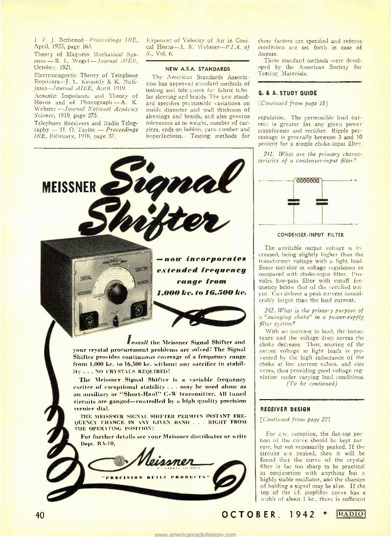
J. F. J. Bethenod- Procccdings IRE, April, 1923, page 163.
Theory of Magneto Mechanical Sys- tems - R. L. Wegel - Journal AIEE, October, 1921.
Electromagnetic Theory of Telephone Receivers -J. L. Kennedy & K. Nufi- jama- Journal AIEE, April 1919.
Acoustic Impedance and Theory of Horns and of Phonograph - A. K. Webster - Journal National Academy Science, 1919, page 275. Telephone Receivers and Radio Teleg- raphy - H. O. Taylor - Proceedings IRE, February, 1918, page 37.
Exponent of Velocity of Air in Coni- cal Horns -A. K. \Vebster- P.I.A. of S., Vol. 6.
NEW A.S.A. STANDARDS
The American Standards Associa- tion has approved standard methods of testing and tolerances for fabric tubu- lar sleeving and braids. The new stand- ard specifies permissible variations on inside diameter and wall thickness of sleevings and braids, and also governs tolerances as to weight, number of car- riers, ends on bobbin, yarn number and imperfections.- Testing methods for
CA MEISSNER eWe4p
now incorporates extended frequency
range from 1.000 he. to I6.500 kc.
40
Install the Meissner Signal Shifter and your crystal procurement problems are solved! The Signal Shifter provides continuous coverage of a frequency range from 1,000 kc. to 16,500 kc. without any sacrifice in stabil- ity ... NO CRYSTALS REQUIRED!
The Meissner Signal Shifter is a variable frequency exciter of exceptional stability ... may be used alone as an auxiliary or "Short- Haul" C -W transmitter. All tuned circuits are ganged- controlled by a high quality precision vernier dial.
THE MEISSNER SIGNAL SHIFTER PERMITS INSTANT FRE- QUENCY CHANGE IN ANY GIVEN BAND . . . RIGHT FROM THE OPERATING POSITION!
For further details see your Meissner distributor or write Dept. RA -10,
O S
" P R E C I S I O N F I C I L T PRODUCTS,'
these factors are specified and referee conditions are set forth in case of dispute.
These standard methods were devel- oped by the American Society for Testing Materials.
Q. & A, STUDY GUIDE
[Continued from page 18]
regulation. The permissible load cur- rent is greater for any given power transformer and rectifier. Ripple per- centage is generally between 3 and 10 percent for a simple choke -input filter.
241. What are the primary charac- teristics of a condenser -input filter?
T ? CONDENSER -INPUT FILTER
The available output voltage is in- creased, being slightly higher than the transformer voltage with a light load. Some sacrifice in voltage regulation as compared with choke -input filter. Pro- vides low -pass filter with cutoff fre- quency below that of the rectified out- put. Can deliver a peak current consid- erably larger than the load current.
242. What is the primary purpose of a "swinging choke" in a power -supply filter system?
With an increase in load, the induc- tance and the voltage drop across the choke decrease. Thus, soaring of the output voltage at light loads is pre- vented by the high inductance of the choke at low current values, and vice versa, thus providing good voltage reg- ulation under varying load conditions.
(To be continued)
RECEIVER DESIGN
[ Continued from page 22]
For c.w. reception, the flat -top por- tion of the curve should be kept nar- row, but not necessarily peaked. If the circuits are peaked, then it will be found that the curve of the crystal filter is far too sharp to be practical in conjunction with anything but a highly stable oscillator, and the chances of holding a signal may be slim. If the top of the i.f. amplifier curve has a width of about 1 kc., there is sufficient
OCTOBER, 1942 RADIO
www.americanradiohistory.com
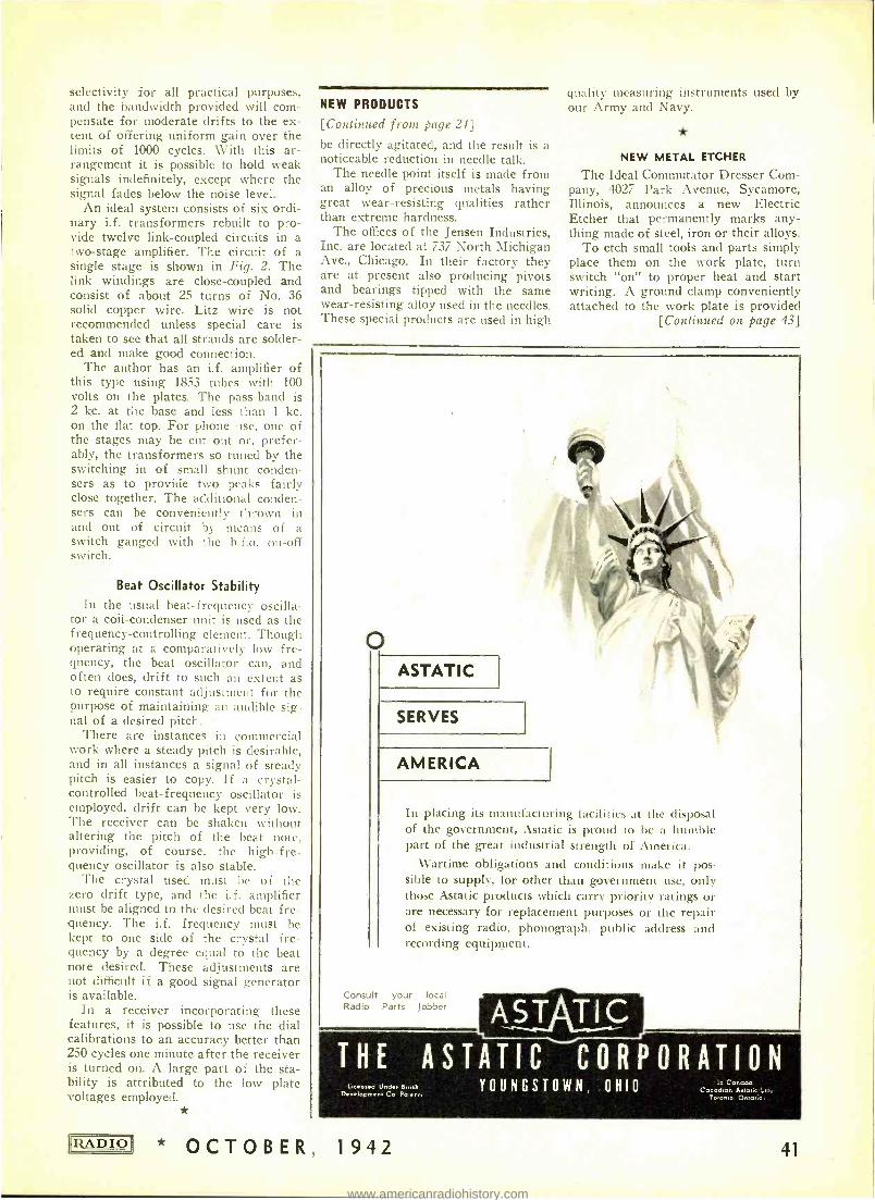
selectivity for all practical purposes, and the bandwidth provided will com- pensate for moderate drifts to the ex- tent of offering uniform gain over the limits of 1000 cycles. With this ar- rangement it is possible to hold weak signals indefinitely, except where the signal fades below the noise level.
An ideal system consists of six ordi- nary i.f. transformers rebuilt to pro- vide twelve link -coupled circuits in a two -stage amplifier. The circuit of a single stage is shown in Fig. 2. The link windings are close -coupled and consist of about 25 turns of No. 36 solid copper wire. Litz wire is not recommended unless special care is taken to sec that all strands are solder- ed and make good connection.
The author has an i.f. amplifier of this type using 1853 tubes with 100 volts on the plates. The pass -band is 2 kc. at the base and less than 1 kc. on the flat top. For phone use, one of the stages may be cut out or, prefer- ably, the transformers so tuned by the switching in of small shunt conden- sers as to provide two peaks fairly close together. The additional conden- sers can be conveniently thrown in and out of circuit by means of a switch ganged with the h.f.o. on -off switch.
Beat Oscillator Stability In the usual beat - frequency oscilla-
tor a coil -condenser unit is used as the frequency -controlling element. Though operating at a comparatively low fre- quency, the beat oscillator can, and often does, drift to such an extent as to require constant adjustment for the purpose of maintaining an audible sig- nal of a desired pitch.
There are instances in commercial work where a steady pitch is desirable, and in all instances a signal of steady pitch is easier to copy. If a crystal - controlled beat -frequency oscillator is employed, drift can be kept very low. The receiver can be shaken without altering the pitch of the beat note, providing, of course, the high -fre- quency oscillator is also stable.
The crystal used must he of the zero drift type, and the i.f. amplifier must be aligned to the desired beat fre- quency. The i.f. frequency must be kept to one side of the crystal fre- quency by a degree equal to the beat note desired. These adjustments are not difficult if a good signal generator is available.
In a receiver incorporating these features, it is possible to use the dial calibrations to an accuracy better than 250 cycles one minute after the receiver is turned on. A large part of the sta- bility is attributed to the low plate voltages employed.
*
11RADIO
NEW PRODUCTS
[Continued front page 24]
be directly agitated, and the result is a noticeable reduction in needle talk.
The needle point itself is made from an alloy of precious metals having great wear -resisting qualities rather than extreme hardness.
The offices of the Jensen Industries, Inc. are located at 737 North Michigan Ave., Chicago. In their factory they are at present also producing pivots and bearings tipped with the same wear -resisting alloy used in the needles. These special products are used in high
quality measuring instruments used by our Army and Navy.
NEW METAL ETCHER
The Ideal Commutator Dresser Com- pany, 4027 Park Avenue, Sycamore, Illinois, announces a new Electric Etcher that permanently marks any- thing made of steel, iron or their alloys.
To etch small tools and parts simply place them on the work plate, turn switch "on" to proper heat and start writing. A ground clamp conveniently attached to the work plate is provided
[Continued on page 43]
o ASTATIC
SERVES
AMERICA
In placing its manufacturing facilities at the disposal of the government, Astatic is proud to be a humble part of the great industrial strength of America.
Wartime obligations and conditions make it pos- sible to supply, for other than government use, only those Astatic products which carry priority ratings or are necessary for replacement purposes or the repair of existing radio. phonograph. public address and recording equipment.
Consult your local Radio Parts Jobber AST TIC THE ASTATIC CORPORATION
Licensed Under Btt.sh Development Co Patens,
YOUNGSTOWN, OHIO In Coneda
Canodtan Aslaiic Lid Toronto Ontano.
* OCTOBER, 1942 41
www.americanradiohistory.com
SPECIAL SUBSCRIPTION OFFER FOR A LIMITED TIME
TEAR OUT AND MAIL'
"RADIO" Radio Magazines, Inc. 132 W. 43rd St., New York City
SIRS: Please send me the next .... issues of RADIO. Here is my check (or E money order) for $
(Remit by Check or Money Order. We cannot assume responsibility for cash sent thru mails)
Name Iprint carefully) ........................ Address City State
Name of Firm You Work For
Title or Position You Hold (please be explicit) ...
15 Big Issues-$3.00
27 Big Issues -$5.00
regular price is $3.00 for 12 issues
regular price is
$5.00 for 24 issues
Special: Subscription price to men in the armed service $1.50 per year
"RADIO" is edit- ed for engineers, designers, tech- nicians, produc- tion men, and operations per- sonnel.
"RADIO" -The only magazine devoted exclu- sively to radio research, design, production and operation.
"RADIO" is not sold on newsstands. To obtain
copies regularly enter a regular subscription order.
Take advantage of the special rate now in effect for
orders sent direct to our circulation department.
Use the Coupon Below It must be filled -in completely.
'TEAR OUT AND MAI
SPECIAL MONEYSAVING OFFER
15 issues $3.00 -27 issues $5.00
42 OCTOBER, 1942 RADIO
www.americanradiohistory.com
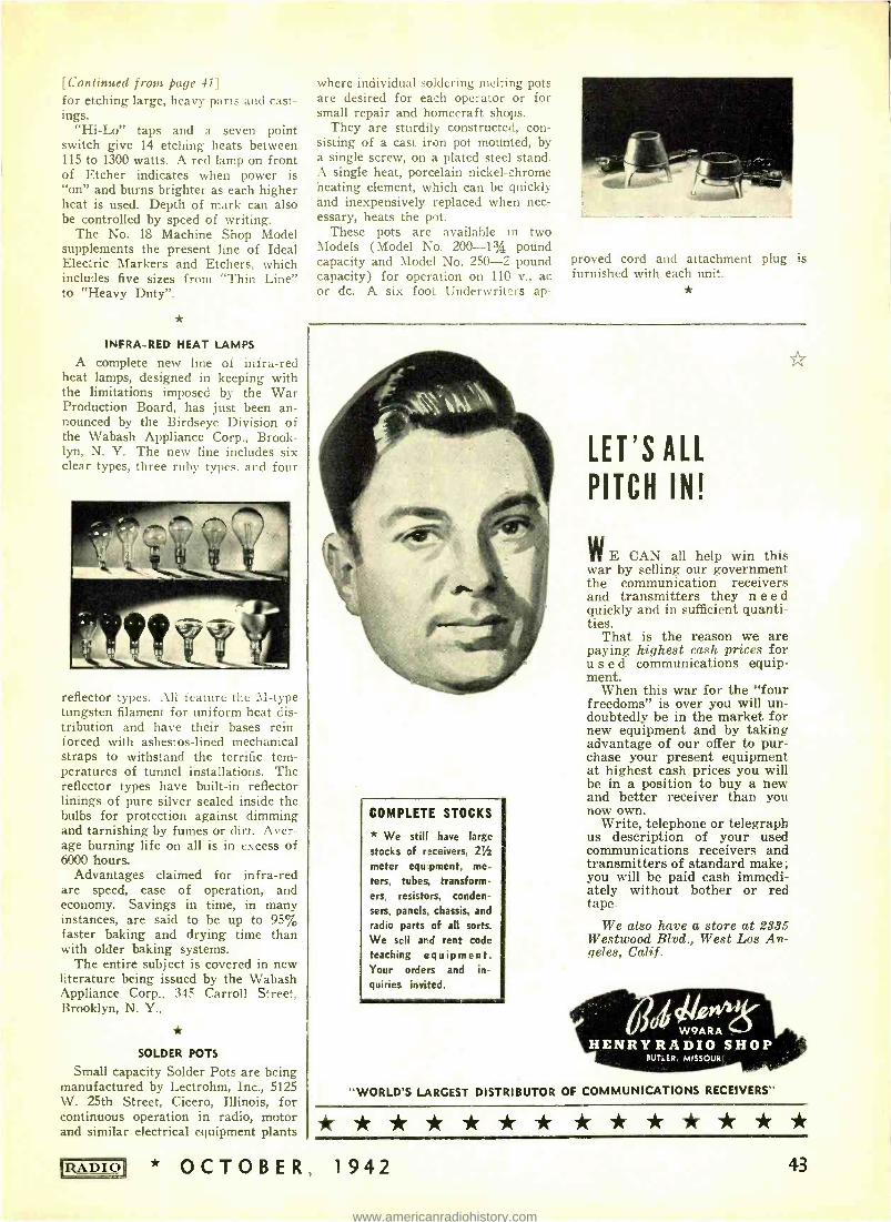
[Continued from page 41] for etching large, heavy parts and cast- ings.
"Hi -Lo" taps and a seven point switch give 14 etching heats between 115 to 1300 watts. A red lamp on front of Etcher indicates when power is "on" and burns brighter as each higher heat is used. Depth of mark can also be controlled by speed of writing.
The No. 18 Machine Shop Model supplements the present line of Ideal Electric Markers and Etchers, which includes five sizes from "Thin Line" to "Heavy Duty ".
INFRA -RED HEAT LAMPS
A complete new line of infra -red heat lamps, designed in keeping with the limitations imposed by the War Production Board, has just been an- nounced by the Birdseye Division of the Wabash Appliance Corp., Brook- lyn, N. Y. The new line includes six clear types, three ruby types, and four
reflector types. All feature the M -type tungsten filament for uniform heat dis- tribution and have their bases rein- forced with asbestos -lined mechanical straps to withstand the terrific tem- peratures of tunnel installations. The reflector types have built -in reflector linings of pure silver sealed inside the bulbs for protection against dimming and tarnishing by fumes or dirt. Aver- age burning life on all is in excess of 6000 hours.
Advantages claimed for infra -red are speed, ease of operation, and economy. Savings in time, in many instances, are said to be up to 95% faster baking and drying time than with older baking systems.
The entire subject is covered in new literature being issued by the Wabash Appliance Corp., 345 Carroll Street, Brooklyn, N. Y.,
SOLDER POTS
Small capacity Solder Pots are being manufactured by Lectrohm, Inc., 5125 W. 25th Street, Cicero, Illinois, for continuous operation in radio, motor and similar electrical equipment plants
where individual soldering melting pots are desired for each operator or for small repair and homecraft shops.
They are sturdily constructed, con- sisting of a cast iron pot mounted, by a single screw, on a plated steel stand. A single heat, porcelain nickel - chrome heating element, which can be quickly and inexpensively replaced when nec- essary, heats the pot.
These pots are available in two Models (Model No. 200 -13/4 pound capacity and Model No. 250-2 pound capacity) for operation on 110 v., ac or dc. A six foo` Underwriters ap-
proved furnished with each unit.
cord and attachment plug is
COMPLETE STOCKS
* We still have large
stocks of receivers, 21 meter equipment, me- ters, tubes, transform- ers, resistors, conden- sers, panels, chassis, and radio parts of all sorts. We sell and rent code teaching equipment. Your orders and in- quiries invited.
LET'S ALL
PITCH IN!
WE CAN all help win this war by selling our government the communication receivers and transmitters they need quickly and in sufficient quanti- ties.
That is the reason we are paying highest cash prices for used communications equip- ment.
When this war for the "four freedoms" is over you will un- doubtedly be in the market for new equipment and by taking advantage of our offer to pur- chase your present equipment at highest cash prices you will be in a position to buy a new and better receiver than you now own.
Write, telephone or telegraph us description of your used communications receivers and transmitters of standard make; you will be paid cash immedi- ately without bother or red tape.
We also have a store at 2335 Westwood Blvd., West Los An- geles, Calif.
W9ARA HENRY RADIO SHOP
BUTLER, MISSOURI
"WORLD'S LARGEST DISTRIBUTOR OF COMMUNICATIONS RECEIVERS"
* OCTOBER, 1942 43
www.americanradiohistory.com
GRAPHITE SHIELDING
[Continued from page 14]
slow heat drying under pressure will discourage any curling. Surfaces, if necessary, may be coated after such treatment.
Numerous non -conducting materials
used for enclosing radio or similar equipment can be readily painted on the inside for shielding purposes. This practice, already common to makers of electronic musical instruments, may soon be adapted by commercial radio producers as metal becomes unavail- able for chassis forms.
PEAS
... ;ïi;:. ,, ;> »,w.
IN A POD. The expression "As alike as peas in a pod" carries a deep engineering sig- nificance. It suggests close duplica- tion, rigid tolerances, or, as Mallory says, "Precision ".
Precision distinguishes Mallory prod- ucts. It permits stability of design, eliminates hit -or -miss manufacturing, stops rejects in inspection, insures uni- formity of the finished product . . .
without the penalty of price.
Whether it be vibrators, Vibrapacks *,
dry electrolytic or mica transmitting and receiving condensers, vitreous resistors, dry -disc rectifiers, volume - controls, potentiometers, rheostats, radio hardware, battery- chargers, or other merchandise ... all Mallory prod- ucts stand out for uniformity, appear- ance and performance. `Reg. U.S. Pat. Off.
P. R. MALLORY & CO., Inc. INDIANAPOLIS INDIANA
Cable Address - PELMALLO
Use
ALLOR APPROVED
PRECISION PRODUCTS
44
Vacuum Tubes
When metal radio tubes and metal shields for glass tubes are unavailable, shield the glass types by covering the outside with colloidal graphite. One part of the paste mixed thor- oughly in three to five parts of water will serve the purpose. Apply by painting or spraying.
If the tubes are the type that generate considerable heat dur- ing operation, apply the graph- ite film in a lattice or screen fashion. Overlap the strips well at the intersections and make them as continuous as possible with sizeable portions of the glass surface untouched. A fine camels' hair brush will be found useful.
Both types of coatings may he grounded by continuing the covering wholly or in a single narrow strip down over the walls of the tube base to touch a lead mounted on the top of the baseboard or chassis. Tubes having grid connections at the top are coated only to within half an inch of the metal.
Grounding may also be made by fitting a loop of copper wire or strip about the tube, clamp fashion. Do this before apply- ing the colloidal graphite solu- tion, and seal the connection well at the edges with the con- centrated graphite paste. If the graphite coating should be ap- plied first, paint both sides of the metal clamps before placing them in position. A third coat overlapping the coated metal and the graphited glass will in- sure good electrical contact.
The "cats' whisker" method shown in the illustration like- wise offers possibilities. A single, small gauge copper wire. appropriately anchored at one end with a wood screw or bolt, is bent to touch lightly the graphited surface of the tube. A spot of concentrated colloi- dal graphite will hold the wire or "whisker" in place. Var- nish or shellac applied over the dried mass will further strengthen the connection.
OCTOB
Shields
Cardboard mailing tubes of sufficient length and diameter to accommodate the tube within, make ideal shields when impregnated and surface -coated with colloidal graphite. A solution con- taining one part of this material and ten parts by volume of water is recom- mended for the initial saturating treat- ment by simple immersion. Fibrous materials of a porous nature particu- larly benefit. Where hard, glazed, or not too porous surfaces are involved, a more concentrated dispersion (1 to 2) can be applied directly to the sub- stitute shield by painting.
Ordinary metal eyelets common to the leather trade, make good ground connections for cardboard shields bear- ing graphite films. A lead is soldered into the opening before the piece is in- serted in the shield walls. The usual precautions for sealing around the con- tact apply. Clamp and whisker type connections are likewise feasible for these enclosures. Eyelets, in turn, make good angle strip fasteners for support- ing the shield on the chassis.
Other applications involving the once abundant metal supplies may suggest themselves from the foregoing re- marks. In such instances the electrical conducting properties of colloidal graphite films are worth investigating.
UNIVERSAL A.C. BRIDGE
[Continued from page 13]
gang equal -section variable condenser and may be calibrated directly in fre- quency depending on the values of Re and RD to satisfy equation (2). If a ten -to -one capacity range can be se- cured with Ce and CD, then values of Re and RD can be found to cover the audio spectrum in three ranges; 20- 200, 200 -2000 and 2000 -20,000 cycles, for a single calibration scale on the condenser.
For an exhaustive treatment of a.c. bridges the reader is referred to "Al- ternating- Current Bridge Methods" by B. Hague, published by Pitman Pub- lishing Corp., and numerous articles in the General Radio Experimenter.
NEW WPB PREFERENCE RATING
Assignment of preference ratings to facilitate the acquisition of equipment and supplies for the maintenance and repair of radio communication and commercial sound - recording facilities is provided in Preference Rating Order P -133, issued October 5th by the War Production Board.
E R , 1942 * RADIO!
www.americanradiohistory.com
The order may not be used for any expansion, improvement or change of design of equipment. It covers only materials needed for maintenance and repair and assigns the preference rating A -I -j to all operators of radio com- munication facilities, including broad- casting, police, direction finding and aviation facilities, as well as all com- mercial sound -recording studios. The
rating, however, is assigned only after the operator has complied with nine conditions stipulated in the order.
These include: The rating may not be used to re-
place in inventory more than one spare tube for each active tube socket.
The rating may not be used to re- place in inventory any spare parts ex- cept those subject to frequent failure,
deterioration, or other exhaus- tion and those which are so spe- cial that failure would inevi- tably result in long delay in re- sumption of essential opera- tions.
The rating may not be used in any case to increase the value of an operator's inventory of repair parts, other than tubes, above the value of such inven- tory as of October 5th.
The rating may not be used to replace in inventory a new part if the defective part can be repaired with a smaller con- sumption of raw material.
The tube which has been re- placed from operator's inven- tory or for which replacement is required must be operated to failure.
The operator must return to the manufacturer any power tube rated at 25 watts or more which has failed, unless the tube is to be repaired.
Equipment which has failed must have been operated within the ratings specified by the manufacturer.
The ratings must not be used to build up inventory of oper- ating supplies other than tubes, in excess of requirements for a three -month period.
The operator must be actively engaged in one of the activities listed on schedule A, attached to the order, or must receive specific authorization for his in- stallation from the Director General for Operations of WPB.
Schedule A lists three cate- gories: radio communication, including broadcasting; sound recording for commercial pur- poses, and radio direction - finding.
Preference ratings for main- tenance and repair of radio communication equipment for- merly were assigned by P -129, which expired September 30. The new order replaces this one, and extends the field some- what, since P -129 was primari- ly designed to cover mainte- of telephone equipment.
PI EZO >.v,yY.?a!u+ain,,,,;,
Well known in the scientific field are the Curies. In 1880 Pierre Curie and his wife discovered that electric charges could be developed by distorting pieces cut from natural quartz crystals. This phenomenon was termed the - piezo- electric effect" by derivation from the Greek word piezen meaning to press.
Subsequent to the Curies' original work, it has been noted that many other substances also exhib_t piezoelectric effects. Ou:standing cf them is the, gem tourmaline, Rochelle Salts, and common sugar. Quartz, however, still is the only substance which possesses the neces- sary strength, physical stability and electrical characteristics required for oscillating crystals. The raw material comes from Brazil -many of the finished military crystal units ceme from Bliley.
T Y P E 3 l
BLILEY FHEaUENCì COV1RQL
,F hAAI,
RI. 9E» 7118 Kr.
.
--.:R4E PA-:_.`,..,
BLILEY ELECTRIC CO., ERIE, PA.
EI,BfTQOiVIC -a
IIIIIUTO1I-TYPE
PifliEli SIPPLIES
a small unit
in a big war .. but an important
one, nonetheless!
On AIRCRAFT CARRIERS ...TANKS
...WARPLANES .. WALKIE TALKIES
. JEEPS ... MOBILE AMPLIFIERS
. P -T BOATS ... and other
military equipment ... Elec-
tronic Vibrator -Type Power
Supplies are establishing new and
amazing records for top perform-
ance and absolute dependability.
ELECTRONIC LABORATORIES
INC.
INDIANAPOLIS, INDIANA
IRA DIO1 * OCTOBER, 1942 45
www.americanradiohistory.com
v Standard Electro -Voice engineering
practise includes orders for "Test to Destruction" during manufacture and assembly. At frequent intervals, micro- phones are taken from our production lines and abused until they are com- pletely demolished.
Throughout the procedure, Electro -Voice engineers carefully examine and analyze the resulting changes in level and response. This is but one of a series of tests that are perfecting a line of rugged microphones for depend- able service under the strains and shocks of military service.
ELECTRO -VOICE MFG. CO., Inc. 1239 SOUTH BEND AVENUE SOUTH BEND, INDIANA
Export Office: 100 VARICK STREET, NEW YORK, N. Y.
,;
r `r///y E MOTORS
PLANTS + GEN- -
. D.C. MOTORS + POWER
R GENERATORSEN-E-MO y, YORK
DYNAMOTORS CONVERTIES G
ILLINOIS SIMON\0.10E, NE
OYNAM 1PI REF
, CARLE CHICAGO Y..
ERROR ADDRESS: 25
MA,IREN STREET, N'
,..a _ ..... C: î ffi
46
NAVY NEEDS TECHNICIANS
Among the most urgent needs of new officer personnel in the United States Navy is for professional technicians in engineering fields, the Director of Naval Officer Procurement, Chicago, has announced.
Perhaps first in the list are graduate electrical engineers, those mainly be- tween 21 and 50 years who have fol- lowed electrical engineering since their graduation, and who have a knowledge of ultra - high frequencies, electronics and television. Those more familiar with power engineering likewise may find a place in the Navy which is in- terested in these men in ages up to 50 years. Electrical engineers are needed especially in the Navy's fields of radio and detection devices. Men with radio or communication engineering degrees may qualify for officers' commissions as well. Waivers for minor physical defects often are obtainable.
A Petty Officer rating is offered to men with sufficient experience in radio to instruct classes in Radio Theory, Practical Operation, Code, or Main- tenance.
The Navy has schools in several parts of the country to instruct enlisted men in radio, and it is for these schools that instructors are needed.
In some cases men with B.S. degrees in mechanical or other engineering subjects and who have had experience in radio and electrical work may qual- ify for officer assignments in radio or
*
Robert E. Sherwood, director of the overseas
branch of the Office of War Information, throws the switch setting into operation the new 100 kilowatt transmitter of General Electric's short wave- station WGEC in
Schenectady, making it one of the most powerful in the western hemisphere. Standing beside him is W. J. Purcell, left, engineer of
G -E broadcasting.
OCTOBER, 1942 * RADIO
www.americanradiohistory.com
electrical lines. Usually, however, de- grees in engineering other than elec- trical tend to fit the applicant for other duty. For instance, Navy activities in ordnance, construction, and ship oper- ation use mechanical, civil, and chemi- cal engineers. Here again physical waivers often are possible and the age range is usually between 30 and 45 years, or beyond those two limits in some cases.
Another special officer procurement program under way is for college teachers of physics, or chemical, Diesel, electrical, mechanical, and radio engi- neering at Naval Reserve Midshipman Schools. Private school and junior col- lege teachers and others qualified to teach those subjects in colleges also are being sought.
Either Ensign W. W. Hall, Room 300, or M. G. Miller, Room 1184, both in the Board of Trade Building, Chi- cago, will answer all requests for in- formation.
PLUG ASSEMBLIES
Universal Microphone Co., Ingle- wood, Cal., is now delivering complete plug assemblies for types PL -54, PL -55, PL -68, JK -26, JK -48 and companion plug and SW -141 for government or- ders through regular purchasing chan- nels. They are not merely plug shells,
but the complete assembly for land, sea and other field communications de- vices.
BOOKLET ON TUBE LIFE
A booklet just released by the Radio, Television and Electronics Department of General Electric Company, Schenec- tady, N. Y., tells how to make radio transmitting tubes last longer. These include the pure tungsten- filament tubes, mercury vapor tubes, and thori- ated tungsten tubes. The booklet is available on request.
* NEW SOLAR CATALOG
Latest catalog to be issued by Solar Manufacturing Corporation of Bay- onne, N. J., describes in full the Solar line of D.C. Type Electrolytic Capaci- tors.
The new catalog, consists of 32 pages, profusely illustrated, and the data has been especially arranged for design engineers. It is listed as Cata- log 12- Section A and may be had only on letterhead request.
SIGNAL CORPS WAIVER
Until further notice, approval by Sig- nal Corps General Development Lab- oratory of preproduction samples of
- epen s on COMMUNICATIONS On America's far -flung battle fronts, radio com- munications are speeding the ultimate victory. At home and abroad, wherever our combat units are in training or in action, BUD Products prove their dependability under all conditions. BUD RADIO, Inc. Cleveland, Ohio
RADIO * OCTOBER, 1942
New OHMITE ax.(.G7 (.e/e7hezl-tee Catalog 18 FREE
Gives up -to -date information on the wide range of Ohmite stock resist- ors, rheostats, chokes and switches used in a 1 types of applications. Helps you select the right units for each job easily, quickly. Send for Catalog 1B now - it Free.
Handy OHMITE ekm,S4
CALCULATOR
Figures ohms watts, volts, amperes -quickly, easily. Solves any Ohm's Law problem with one setting of the slide. All values are direct read- ing. No slide rule knowledge neces- sary. Size 4/8 ̀ z 9 ".
Yours for only loc. At your Jobber or send coupon.
44416IOHMITE MANUFACTURING CO.
4866 Monolog St., Chicago, U.S.A.
Send Free Catalog 18 tcl enclosed.
Send Ohm's
10c in
Name- Address
Or)
Suataadtc '42
/e4-.>2t ®F;I nr[
47
www.americanradiohistory.com
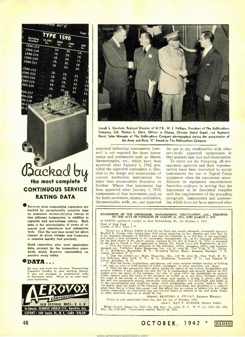
1590-217 1590-218 1590-219 1590-220 1590-221
1590-222 1590-223 1590-224 590-225 590-226
90-227 90-228 90-229
0-2
16.
16.
18. 18. 18.
20. 20. 20. 20,
15. 15.
17. 18.
20, 18. 18. 18.
18. 18.
22. 22. 22.
22.
22.
ÖìackacQ the most complete
CONTINUOUS SERVICE
RATING DATA
0 Aerovox mica transmitting capacitors are backed by exceptionally complete data on maximum current -carrying ratings at five different frequencies, in addition to capacity and test -voltage ratings. Such data is the accumulation of years of re- search and experience and exhaustive tests. Thus the unit best suited for given current at given voltage and frequency is selected quickly and precisely.
Good capacitors, plus good application data, account for the tremendous popu- larity which Aerovox transmitting ca- pacitors enjoy today.
ODATA... Be sure you have the Aerovox Transmitting Capacitor Catalog in your working library, if you are engaged in professional radio or electronic work. Write us on your busi- ness stationery.
NEW BEDFORD, MASS., U. S. A.
In Canada: AEROVOX CANADA LTD., Hamilton, Ont.
EXPORT: 100 Varick St., N. Y., Cable `ARLAB'
48
Joseph L. Overlock, Regional Director of W.P.B., W. J. Halligan, President of The Hallicrafters Company, Col. Thomas L. Clark, Officer in Charge, Chicago Signal Depot, and Raymond Durst, Sales Manager of The Hallicrafters Company photographed during the presentation of
the Army and Navy "E" Award to The Hallicrafters Company.
electrical indicating instruments (met- ers) is not required for those instru- ments and accessories such as shunts, thermocouples, etc., which have been approved after January 1, 1942, pro- vided the approved instrument is iden- tical to the design and construction of current production instruments for other than conservation directives on finishes. Where that instrument has been approved after January 1, 1942, components of that instrument, such as the basic movement, shunts, multipliers, thermocouples, scale, etc., are approved
for use in any combination with other previously approved components in that general case size and construction.
To carry out the foregoing, all pro- curement agencies and their represen- tatives have been instructed to accept instruments for use in Signal Corps equipment when the instrument manu- facturer or equipment manufacturer furnishes evidence in writing that the instrument to be furnished complies with the requirements of the preceding paragraph. Instruments and accessor- ies, which have not been approved after
STATEMENT OF THE OWNERSHIP, MANAGEMENT, CIRCULATION, ETC., REQUIRED BY THE ACTS OF CONGRESS OF AUGUST 24, 1912, AND MARCH 3, 1933
of RADIO, published monthly at East Stroudsburg, Pa., for October 8, 1942. State of New York 1
County of New York 1 Ss..
Before me, a Notary Public in and for the State and county aforesaid, personally appeared Sanford R. Cowan, who, having been duly sworn according to law, deposes and says that he is the Business Manager of RADIO, and that the following is, to the best of his knowledge and belief, a true statement of the ownership, management, etc., of the aforesaid publication for the date shown in the above caption, required by the Act of August 24, 1912, as amended by the Act of March 3, 1933, embodied in section 537, Postal Laws and Regulations, to wit:
1. That the names and addresses of the publisher, editor, managing editor and business manager are: Publisher, Radio Magazines, Inc., 132 W. 43rd St., New York N. Y.; Editor, M. L. Muhleman, Bronxville, N. Y.; Managing Editor, None; Business Manager, S. R. Cowan, Brooklyn, N. Y.
2. That the owners are: Radio Magazines, Inc., 132 W. 43rd St., New York, N. Y.; Lee Robinson, New York, N. Y. ; M. L. Muhleman, Bronxville, N. Y. ; and Sanford R. Cowan, Brooklyn, N. Y.
3. That the known bondholders, mortgagees, and other security holders owning or holding 1 per cent or more of total amount of bonds, mortgages, or other securities, are: None.
4. That the two paragraphs next above, giving the names of the owners, stockholders and security holders, if any, contain not only the list of stockholders and security holders as they appear upon the books of the company, but also, in cases where the stockholder or security holder appears upon the books of the company as trustee or in any other fiduciary relation, the name of the person or corporation for whom such trustee is acting, is given; also that the said two paragraphs contain statements embracing affiant's full knowledge and belief as to the circumstances and conditions under which stockholders and security holders who do not appear upon the books of the company as trustees, hold stock, and securities in a capacity other than that of a bona fide owner; and this alliant has no reason to believe that any other person, association, or corporation has any interest direct or indirect in the said stock, bonds, or other securities than as so stated by him.
(Signed) SANFORD R. COWAN, Business Manager. Sworn to and subscribed before me, this 8th day of October, 1942.
(Seal.) RAY F. WIESEN, Notary Public. Kings County, Kings Co. Clk's No. 208, Reg. No. 4245, N. Y. N. Y. Co. Clk's No. 694,
Reg. No. 4 -W -398. Commission expires March 30, 1944.
OCTOBER, 1942 * RADIO
www.americanradiohistory.com
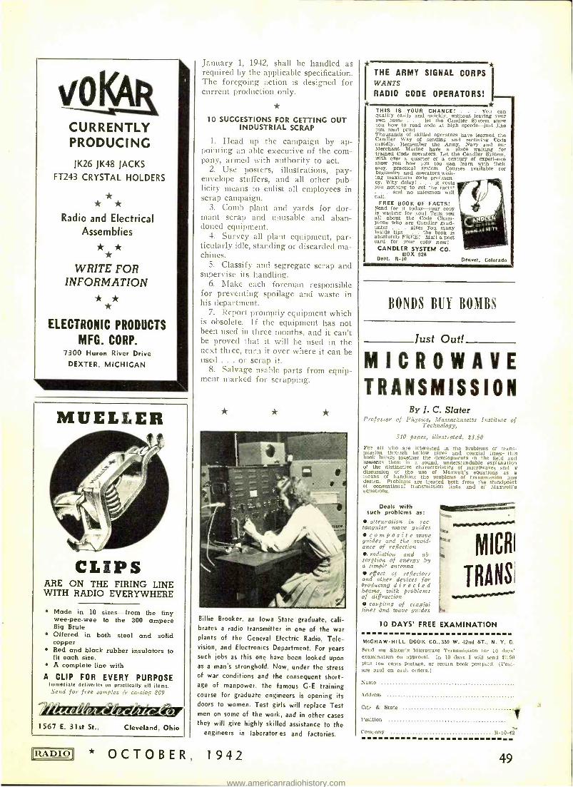
CURRENTLY PRODUCING
JK26 JK48 JACKS
FT243 CRYSTAL HOLDERS
* * * Radio and Electrical
Assemblies
* * * WRITE FOR
INFORMATION * *
ELECTRONIC PRODUCTS
MFG. CORP. 7300 Huron River Drive
DEXTER, MICHIGAN
MUELLER
CLIPS ARE ON THE FIRING LINE WITH RADIO EVERYWHERE
Made in 10 sizes -from the tiny wee -pee -wee to the 300 ampere Big Brute Offered in both steel and solid copper Red and black rubber insulators to fit each size. A complete line with
A CLIP FOR EVERY PURPOSE Immediate deliveries on practically all items. Send for free samples & catalog 809
1567 E. 31st St., Cleveland, Ohio
LRADIOI * OCTOBER,
January 1, 1942, shall be handled as required by the applicable specification. The foregoing action is designed for current production only.
10 SUGGESTIONS FOR GETTING OUT INDUSTRIAL SCRAP
1. Head up the campaign by ap- pointing an able executive of the com- pany, armed with authority to act.
2. Use posters, illustrations, pay - envelope stuffers, and all other pub- licity means to enlist all employees in scrap campaign.
3. Comb plant and yards for dor- mant scrap and unusable and aban- doned equipment.
4. Survey all plant equipment, par- ticularly idle, standing or discarded ma- chines.
5. Classify and segregate scrap and supervise its handling.
6. Make each foreman responsible for preventing spoilage and waste in his department.
7. Report promptly equipment which is obsolete. If the equipment has not been used in three months, and it can't be proved that it will be used in the next three, turn it over where it can be used ... or scrap it.
8. Salvage usable parts from equip- ment marked for scrapping.
*
Billie Brooker, an Iowa State graduate, cali- brates a radio transmitter in one of the war plants of the General Electric Radio, Tele- vision, and Electronics Department. For years such jobs as this one have been looked upon as a man's stronghold. Now, under the stress of war conditions and the consequent short- age of manpower, the famous G -E training course for graduate engineers is opening its doors to women. Test girls will replace Test men on some of the work, and in other cases they will give highly skilled assistance to the
engineers in laborator,es and factories.
1942
f
THE ARMY SIGNAL CORPS WANTS
RADIO CODE OPERATORS! *
THIS IS YOUR CHANCE! . you can quality easily and quickly, without leaving your own home . let the Candler System show you how to read code at high speeds -just dike you read print. Thousands of skilled operators have learned the Candler Way of sending and receiving Code rapidly. Remember the Army, Navy and our Merchant Marine have a place waiting for trained Code operators. Let the Candler System, with over a quarter of a century of experience show you how you too can learn with their easy, practical system. Courses available for beginners and operators wish- ing maximum code proficien- cy. Why delay! . . it costs you nothing to get the facts!
and no salesman will call.
FREE BOOK OF FACTS! Send for it today -your copy is waiting for you! Tells you all about the Code Cham- pions who are Candler grad- uates . . . gives you many inside tips the book is absolutely FREE! Mail a post card for your copy aowl CANDLER SYSTEM CO.
BOX 928 Dept. R -10 Denver. Colorado
BONDS BUY BOMBS
Just Out!
MICROWAVE TRANSMISSION
By J. C. Slater Professor of Physics, Massachusetts Institute of
Technology,
310 pages, illustrated, $3.50
For all who are interested in the problems of trans- mission through hollow pipes and coaxial lines -this book brings together the developments in the field and presents them in a sound, understandable explanation of the distinctive characteristics of microwaves and a! discussion of the use of Maxwell's equations as a means of handling the problems of transmission line design. Problepis are treated both from the standpoint of conventional transmission lines and of Maxwell's equations.
Deals with such problems as:
attenuation in rec- tangular wave guides
composite wave guides and the avoid- ance of reflection
radiation and ab- sorption of energy by a simple antenna a effect of reflectors and other devices for Producing directed beams with problems of diffraction
coupling of coaxial lutes and trave guides
MICHI
TRANS
10 DAYS' FREE EXAMINATION
MCGRAW -HILL BOOK CO..330 W. 42nd ST., N. Y. C.
Send me Slater's Microwave Transmission for 111 slays' examination on approval. In 10 days I will send $3,511
plus few cents postage, or return book postpaid. (Post- age paid on cash orders.)
Name
Address
City & State
Position
Company It-Li-.12
49
www.americanradiohistory.com
EVERYTHING IN RADIO
Sets. parts. supplies. public address systems. amateur equip- ment. testers, kits and fluores- cent lighting at lowest prices. Huge stocks, bought months ago
. ready for shipment the same. day your order is received. The Defense Program is making big demands on our industry but be- cause of our advance buying we are able to fill your orders promptly and efficiently.
BURSTEIN -APPLEBEE COMPANY
1012 -14 *GEE, KANSAS CITY, MO.
ADDRESS CHANGE?
Notify RADIO's Circulation Depart- ment at 132 West 43rd Street, New York, N. Y., of your new
address two or three weeks before you move. The Post Office Depart- ment does not forward magazines sent to a wrong address unless you pay additional postage. We cannot duplicate copies mailed to your old address. Thank you!
ADVERTISING INDEX
Aerovox Corp. 48 Astatic Corp. 41
Bliley Electric Co. 45 Bud Radio, Inc. 47 Burstein -Applebee Co. 50 Candler System Co. 49 Centralab 8
Echophone Radio Co. 25 Eitel- McCullough, Inc- 31
Electronic Laboratories, Inc. 45 Electronic Prod. Mfg. Corp. 49 Electro -Voice Mfg. Co., Inc. 46 Galvin Mfg. Corp. 27 Hallicrafters Co., The 3, 4
Henry Radio Shop 43 Hytron Corp. Cover 4
Jensen Radio Mfg. Co. 6
Johnson Co., E. F. 39 Mallory & Co., P. R. 44 McGraw -Hill Book Co., Inc 49 Meissner Mfg. Co. 40 Mueller Electric Co. 49 National Co., Inc. Cover 3
Ohmite Mfg. Co. 47 Pioneer Gen -E -Motor 46 Radio Magazines, Inc. 42 Simpson Electric Co. 33 Solar Mfg. Co. 38 Triplett Elec. Inst. Co. 28 U. S. Treasury Department 37 United Trans. Co. Cover 2
50
9. Speed return of scrap to mills and refineries through existing chan- nels. Report regularly on collections of scrap to the Industrial Salvage Com- mittee set up by the War Production Board in your community.
10. Enforce monthly re - checks in every department to find scrap mate- rial previously overlooked.
* NEW CONDENSER DISPLAY
In accordance with their plan of dis- tribution, Industrial Condenser Corp., of Chicago, has issued a new counter display to their distributors.
The new counter display stands 18 inches wide by 20 inches high and is of light colored wood with two wood supports which hold the display up- right. Sixteen representative types of condensers are mounted on the board which permits a permanent display of Incco products.
Industrial Condenser Corporation's new plans call for distribution through distributors with stocks being carried at each point to insure immediate de- livery on small lots thereby speeding up shipping of these orders and giving immediate delivery in each distributor's locality.
* UNIVERSAL MIKE PROTECTIVE
SYSTEM
Andrew J. Meagher, in charge of guards and fire forces of the plants of the Universal Microphone Co., at Ingle- wood, Cal., has been appointed per- sonnel director of the company. The entire patrol force of the factory was recently sworn into U. S. Army service as auxiliary military police.
Mr. ' Meagher has a background of 25 years in peace circles as special in- vestigator for the post office and treas- ury departments, as well as a U. S. intelligence unit. He also conducted his own investigation office, and at one time was investigator for the Santa Cruz county grand jury and the district attorney's office in Stockton, Cal.
Expansion of the personnel division includes the installation of an identi- fication bureau with facilities for fin- ger printing and photographing new employees. As an additional feature, Universal will also record the voices of personnel, using paper covered discs which do not use any restricted ma- terial.
Universal's expanded program in- cludes centralized employee hiring through the U. S. Employment Serv- ice ; the installation of a teletype ma- chine to surrounding administrative areas and gas masks for the entire force of auxiliary firemen. -
HALF PRICE SUBSCRIPTIONS . . .
for Men in the U. S. Armed Services
Subscriptions to "RADIO" addressed to men in the U. S. Army, Navy, Marine Corps, or Coast Guard will be accepted at the below -cost rate of $1.50 per year. Subscriptions at this rate (whether ordered by the addressee or a donor) should be accompanied by a remittance in full; addressee's rank and military address must be given. This rate applies wherever domestic U. S. postal service extends, including naval units
at sea and overseas army postoffices. No cancellations or refunds.
Simply write rank, name, and military address on a slip of paper and
send, accompanied by remittance, to
Radio Magazines, Inc., 132 W. 43rd St., New York, N. Y.
* * * * * * * * * * * * * OCTOBER, 1942 IIZADIOII
www.americanradiohistory.com
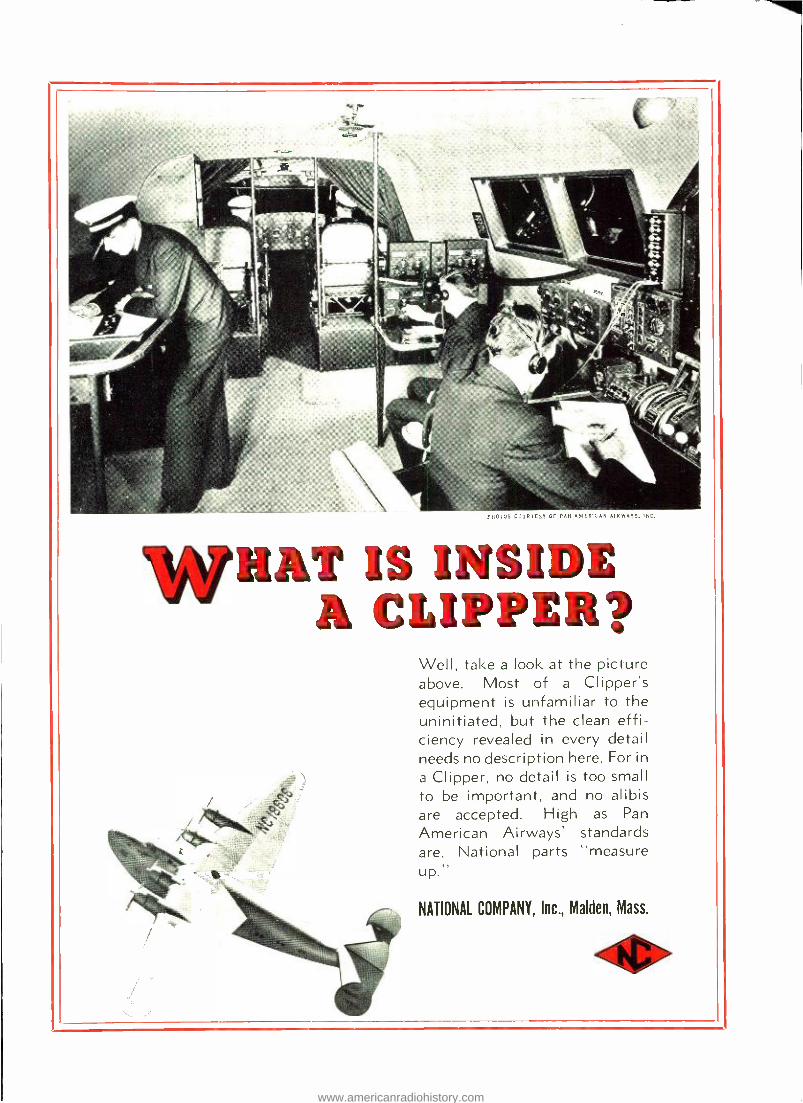
PilOTOS COURTESY OF PAN AMER CA AIR AYS, INC.
WHAT IS INSIDE A CLIPPER?
Well, take a look at the picture above. Most of a Clipper's equipment is unfamiliar to the uninitiated, but the clean effi- ciency revealed in every detail needs no description here. For in
a Clipper, no detail is too small to be important, and no alibis are accepted. High as Pan
American Airways' standards are, National parts "measure up "
NATIONAL COMPANY, Inc., Malden, Mass.
41
www.americanradiohistory.com
p1O° NOT OVER
T RO N is still managing to keep its head "above water." As you know, electronic tubes for this "radio war" are demanded by the armed forces in quantities which tax to the utmost all avail- able productive facilities.
HYTRON has been called upon to do a job which has no
end. The challenge has been met by expansion, emphasis upon types Hytron is best fitted to make, long -range pro- duction planning, -but, primarily, by not taking on more work than can be successfully handled. In this way, assur- ance can be given to all customers that their tubes will be
delivered on time.
EXPANSION -Cooperating fully with the Army and the Navy, Hytron is now realizing a plan of expansion to quadruple its size. New high -speed equipment, newly- recruited operators are being correlated by Hytron en- gineers into a production team at the New - buryport, Mass., plant, even as ever- increas- ing quantities of tubes are rolling off pro- duction lines at the Salem plant.
PRODUCTION PLANNING - Far -sighted planning which devotes Herculean efforts to the material procurement obstacle, and to concentration upon fewer, similar types, keeps production lines running smoothly, constantly, with the least possible, time - wasting changeovers.
SELECTION OF TYPES- By sticking to its last, by concentrating upon special pur- pose tubes which for it are "naturals," Hytron is making a maximum contribution toward winning this war. All of its long years of experience in engineering special- ized tubes are now at the service of the armed forces and their equipment sup- pliers.
HOW YOU CAN HELP- By placing your orders well in advance, by ordering now the tubes you will need this winter, next year, you can help Hytron to fit your tube needs into its production plait -can assure your- self that you will receive your tubes on schedule.
HYTRON CORP., Salem and Newburyport, Mass. . . . Manu/aciurers aJ Radia Tubes Since 1921 . . .
www.americanradiohistory.com