Embed Size (px)
Citation preview
RADIO DIRECTION FINDING NETWORK RECEIVER DESIGN FOR LOW-COST PUBLIC SERVICE APPLICATIONS
A Thesis Presented to the Faculty of
California Polytechnic State University, San Luis Obispo
In Partial Fulfillment
of the Requirements for the Degree
Master of Science in Electrical Engineering
By
Marcel Colman Eric Stieber
December 2012

ii
©2012
Marcel Colman Eric Stieber
SOME RIGHTS RESERVED
This work is licensed under the Creative Commons Attribution-ShareAlike 3.0 Unported
License. This license lets others remix, tweak, and build upon this work even for commercial
purposes, as long as they credit the author and license their new creations under the
identical terms. To view a copy of this license, visit
http://creativecommons.org/licenses/by-sa/3.0/ or send a letter to Creative Commons,
444 Castro Street, Suite 900, Mountain View, California, 94041, USA.

iii
COMMITTEE MEMBERSHIP
TITLE: Radio Direction Finding Network Receiver Design for Low-cost
Public Service Applications
AUTHOR: Marcel Colman Eric Stieber
DATE SUBMITTED: December 2012
COMMITTEE CHAIR: Dr. Clark Savage Turner J.D., Professor of Computer Science
COMMITTEE MEMBER: Dr. Dennis J. Derickson, Professor of Electrical Engineering
COMMITTEE MEMBER: Dr. John A. Saghri, Professor of Electrical Engineering
iv
ABSTRACT
RADIO DIRECTION FINDING NETWORK RECEIVER DESIGN FOR LOW-COST PUBLIC SERVICE APPLICATIONS
Marcel Colman Eric Stieber
A low-cost radio direction finding (RDF) VHF receiver has been investigated for
development into a radio direction finding network (RDFN) with a particular focus towards
public service and commercial asset tracking applications. The primary design criteria were
reproducibility, low-cost, and simplicity such that public service and volunteer
organizations can benefit from the technology. Two receiver designs were built and tested
to allow for comparison of practicality, cost, and accuracy. A pseudo-Doppler RDF and a
time difference of arrival (TDOA) receiver were built as proof-of-concept for a system
design based on commercial off-the-shelf (COTS) components. The pseudo-Doppler system
is a less practical implementation due to the necessity for custom hardware, a large antenna
system, and an increased directional error due to multipath and weak signals. The TDOA
system has potential as a very simple and low-cost RDFN implementation, but requires
extremely accurate time synchronization that is difficult to achieve using COTS GPS receiver
modules. The final proposed solution takes advantage of the simple TDOA hardware and
multiple detection techniques (including signal strength) to produce improved locational
data and ultimately provide a more accurate estimate of position. Further development and
improvements to this receiver design have the potential for implementation as a low-cost
radio direction finding network.
Keywords: Radio Direction Finding Network, Time Difference of Arrival, Pseudo-Doppler,
Time of Arrival, Signal Strength, GPS, Clock Drift, Bias, and Accuracy.

v
Acknowledgements
Countless people have contributed to my thesis both through direct support and in spirit.
My thesis advisor, Dr. Clark Savage Turner WA3JPG, offered to step outside the realm of the
computer science department and share his expertise in antennas and radio systems. Dr.
Dennis Derickson AC0P, Electrical Engineering Department Chair, has been instrumental in
supporting my education and Amateur Radio activities at Cal Poly which ultimately lead to
the development of this project. Thank you to Dr. John Saghri, Professor of Electrical
Engineering, serving as a member of my thesis committee. I also want to acknowledge my
Amateur Radio Elmers (mentors), Ron Patterson W6FM and John Rogers KK6DJ, for their
motivation and knowledge throughout the past 4 years, and my many peers and classmates
that have helped with brainstorming, testing prototypes, and proofreading. Lastly and most
importantly, a thank you to my parents, Hella and Tony, and my sister, Chantal, for their
continued support, high expectations, and daily inspiration to do my best.
-Marcel Stieber, AI6MS

vi
Table of Contents
List of Tables ........................................................................................................................................................... viii
List of Acronyms ................................................................................................................................................... viii
List of Figures ........................................................................................................................................................... ix
1. Introduction ..................................................................................................................................................... 1
2. Project Motivation ......................................................................................................................................... 2
2.1 APRS ........................................................................................................................................................... 2
2.2 Beyond APRS: Public Service Applications ................................................................................ 3
3. Radio Direction Finding Overview .......................................................................................................... 6
4. Existing Technologies and Implementations...................................................................................... 7
4.1 Historical RDF Systems ...................................................................................................................... 7
4.2 Current RDF Applications ............................................................................................................... 10
4.2.1 Civil Air Patrol ............................................................................................................................ 10
4.2.2 Search and Rescue .................................................................................................................... 11
4.2.3 Wildlife Tracking ....................................................................................................................... 12
4.2.4 LoJack Vehicle Tracking ......................................................................................................... 13
4.2.5 Wireless E911 Phase 2 ........................................................................................................... 14
5. Problem Refinement and Scope ............................................................................................................. 15
5.1 Proposed Design Feature List ....................................................................................................... 17
5.2 System Comparison ........................................................................................................................... 17
5.2.1 TDOA .............................................................................................................................................. 18
5.2.2 Pseudo-Doppler ......................................................................................................................... 18
6. Pseudo-Doppler Direction Finding Prototype ................................................................................. 19
6.1 Pseudo-Doppler Direction Finding Theory of Operation................................................... 20
6.1.1 Mechanical vs. Electronic Rotation .................................................................................... 21
6.2 System Overview ................................................................................................................................ 22
6.2.1 Equipment List ........................................................................................................................... 22
6.3 System Design Modification and Construction ...................................................................... 23
6.3.1 Antenna Switcher Design and Construction .................................................................. 23
6.3.2 Antenna Switching Control ................................................................................................... 31
6.4 Pseudo-Doppler RDF System Setup and Testing ................................................................... 36
6.5 Pseudo-Doppler Results .................................................................................................................. 39
6.6 Conclusion on the Pseudo-Doppler Receiver.......................................................................... 40
7. Time Difference of Arrival Direction Finding Prototype ............................................................. 41
7.1 TDOA Overview ................................................................................................................................... 41
7.2 GPS Clock Accuracy and Issues ..................................................................................................... 42
vii
7.3 TDOA System Configuration .......................................................................................................... 43
7.3.1 Equipment List ........................................................................................................................... 44
7.3.2 TDOA System Block Diagram ............................................................................................... 45
7.4 TDOA System Component Validation ........................................................................................ 46
7.4.1 Power Analysis .......................................................................................................................... 46
7.4.2 Friendcom FC-301/D VHF Transmitter Characterization ....................................... 47
7.5 T3-301 APRS Module Configuration .......................................................................................... 50
7.5.1 T3-301 Configuration Software .......................................................................................... 51
7.5.2 T3-301 Device Interfacing..................................................................................................... 52
7.6 TDOA System Results........................................................................................................................ 54
7.6.1 APRS Packet Results ................................................................................................................ 54
7.6.2 COTS Hardware Implementation ....................................................................................... 55
7.6.3 COTS Timing Challenges ........................................................................................................ 55
7.6.4 TDOA Network Implementation ......................................................................................... 56
8. Conclusion and Future Work .................................................................................................................. 57
8.1 Contributions ....................................................................................................................................... 58
8.2 Future Project Developments ....................................................................................................... 59
9. Bibliography ................................................................................................................................................... 61
10. Appendix A: Arduino Antenna Switcher Code ................................................................................. 66
11. Appendix B: NMEA 0183 GGA Packet Format [57][58][60] ...................................................... 68
12. Appendix C: Argent Data Systems T3-301 Schematic [56] ......................................................... 69
13. Appendix D: Antenna Switcher Characterization ........................................................................... 70
viii
List of Tables
Table 1: Comparison of Proposed VHF RDF Network Technologies ................................................ 17
Table 2: TDOA System Power Budget Analysis ......................................................................................... 46
Table 3: FC-301/D Data Radio Characterization ...................................................................................... 48
Table 4: NMEA 0183 GGA Packet Format .................................................................................................... 68
List of Acronyms
APRS - Automatic Position (Packet) Reporting System
ARES - Amateur Radio Emergency Services
COTS - Commercial Off-The-Shelf
DF - Direction Finding
ELT - Emergency Locator Transmitter
E-OTD - Estimated Observed Time Different
GPS - Global Positioning System
NDRS - National Distress and Response System
NMEA - National Maritime Electronics Association
RACES - Radio Amateur Civil Emergency Services
RDF - Radio Direction Finding
RDFN - Radio Direction Finding Network
RF - Radio Frequency
SINAD - SIgnal to Noise And Distortion ratio
SMD - Surface Mount Device
TDOA - Time Difference of Arrival
U-TDOA - Uplink Time Difference of Arrival
VHF - Very High Frequency

ix
List of Figures
Figure 1: A modern H-Dipole Adcock DF Antenna for 20-174MHz[11] ........................................... 7
Figure 2: HFDF "Elephant Cage" Antenna Array[12] ................................................................................ 8
Figure 3: A portable Rescue 21 DF Tower with the Adcock DF array [15] ...................................... 9
Figure 4: L-Tronics Little L-Per Portable Direction Finder[17] ......................................................... 10
Figure 5: Backcountry Access Tracker DTS Avalanche Beacon [19] ................................................ 11
Figure 6: A 170 milligram radio tracking tag on a bee [21] ................................................................. 12
Figure 7: A manual VHF direction finding antenna system for wildlife tracking [22] .............. 12
Figure 8: LoJack vehicle tracking control head unit [23] ...................................................................... 13
Figure 9: PicoDopp MiniMount Antenna Array [30] ............................................................................... 18
Figure 10: A pseudo-Doppler RDF system by Mike Kossor WA2EBY [31] .................................... 19
Figure 11: (A) A rotating monopole antenna and (B) the resultant Doppler frequency
modulation[31] ....................................................................................................................................... 20
Figure 12: Pseudo-Doppler RDF system block diagram ........................................................................ 22
Figure 13: Antenna switcher schematic [29] ............................................................................................. 23
Figure 14: Improved antenna switcher schematic .................................................................................. 24
Figure 15: Graph of 1N4148 diode isolation characteristics under biased and non-biased
conditions .................................................................................................................................................. 25
Figure 16: Antenna switcher PCB with etched traces ............................................................................ 26
Figure 17: Populated antenna switcher PCB .............................................................................................. 26
Figure 18: Completed antenna switching board (using the Improved antenna switcher
schematic from Figure 14) ................................................................................................................. 27
Figure 19: Close-up of Antenna Port 1 and Fm Receiver Port of the Antenna Switcher .......... 28
Figure 20: Antenna 1 DC forward-biased detail diagram ..................................................................... 29
Figure 21: Antenna 1 DC forward-biased RF path diagram ................................................................. 29
Figure 22: Antenna 1 non-biased antenna isolation condition .......................................................... 30
Figure 23: Simplified antenna switching control circuit schematic [29]........................................ 31
Figure 24: Discrete component antenna switching control circuit................................................... 31
Figure 25: Discrete component antenna switching control signals.................................................. 32
Figure 26: Arduino generated antenna switching control signals .................................................... 33
Figure 27: Arduino UNO controller antenna switching tests .............................................................. 34
Figure 28: VX-5R demodulated FM audio output FFT (250Hz per horizontal division) ......... 35
Figure 29: Pseudo-Doppler system test equipment configuration ................................................... 37
x
Figure 30: Pseudo-Doppler RDF test system vehicle installation ..................................................... 37
Figure 31: SoundDoppler screenshot of a 147.36 MHz FM repeater on Mt Lowe ...................... 38
Figure 32: SoundDoppler screenshot of a 146.5 MHz local transmitter with multipath
distortion ................................................................................................................................................... 39
Figure 33: Complete COTS TDOA system with radio, battery, and GPS .......................................... 44
Figure 34: TDOA system block diagram ....................................................................................................... 45
Figure 35: Genesis 12V 12Ah sealed lead-acid battery .......................................................................... 46
Figure 36: Friendcom FC-301/D VHF data radio ..................................................................................... 47
Figure 37: FC-301/D transceiver output spectrum at 144.990MHz (1 watt) .............................. 49
Figure 38: Argent Data Systems T3-301 Tracker Module v1.1 .......................................................... 50
Figure 39: OTWINCFG T3-301 Configuration Utility .............................................................................. 51
Figure 40: Squelch to IRQ jumper wire on the back of the T3-301 ................................................... 52
Figure 41: OTWINCFG Script Editor .............................................................................................................. 53
Figure 42: TDOA Network Configuration .................................................................................................... 56
Figure 43: Antenna switcher characterization test configuration .................................................... 70
Figure 44: Antenna switcher S21 transmission parameters with 0V diode bias ........................ 71
Figure 45: Antenna switcher S21 transmission parameters with 1V diode bias ........................ 72
1
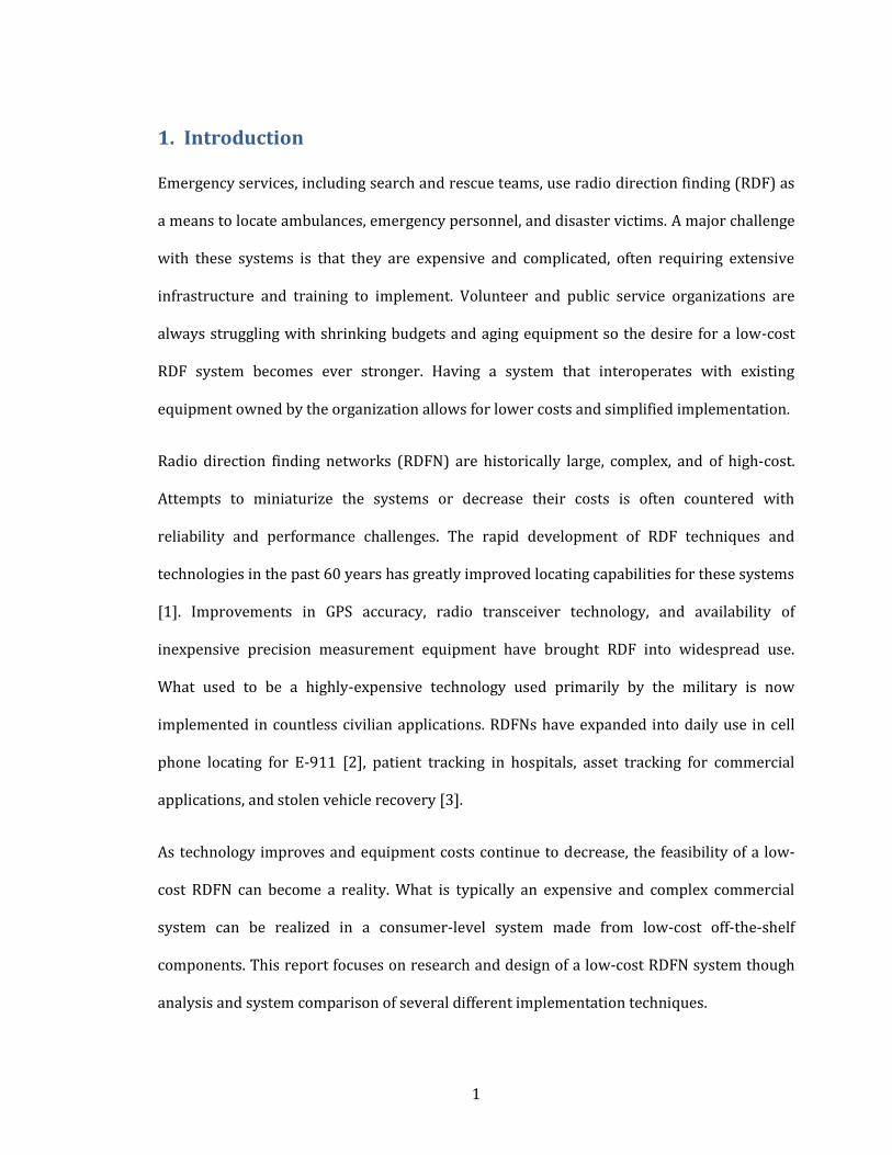
1. Introduction
Emergency services, including search and rescue teams, use radio direction finding (RDF) as
a means to locate ambulances, emergency personnel, and disaster victims. A major challenge
with these systems is that they are expensive and complicated, often requiring extensive
infrastructure and training to implement. Volunteer and public service organizations are
always struggling with shrinking budgets and aging equipment so the desire for a low-cost
RDF system becomes ever stronger. Having a system that interoperates with existing
equipment owned by the organization allows for lower costs and simplified implementation.
Radio direction finding networks (RDFN) are historically large, complex, and of high-cost.
Attempts to miniaturize the systems or decrease their costs is often countered with
reliability and performance challenges. The rapid development of RDF techniques and
technologies in the past 60 years has greatly improved locating capabilities for these systems
[1]. Improvements in GPS accuracy, radio transceiver technology, and availability of
inexpensive precision measurement equipment have brought RDF into widespread use.
What used to be a highly-expensive technology used primarily by the military is now
implemented in countless civilian applications. RDFNs have expanded into daily use in cell
phone locating for E-911 [2], patient tracking in hospitals, asset tracking for commercial
applications, and stolen vehicle recovery [3].
As technology improves and equipment costs continue to decrease, the feasibility of a low-
cost RDFN can become a reality. What is typically an expensive and complex commercial
system can be realized in a consumer-level system made from low-cost off-the-shelf
components. This report focuses on research and design of a low-cost RDFN system though
analysis and system comparison of several different implementation techniques.
2
2. Project Motivation
One of the motivating factors for this project comes from the Amateur Radio community and
a project known as APRS or Automatic Position Reporting System [4]. APRS is an
international standard used for positioning, messaging, and telemetry. Amateur radio
operators world-wide have APRS enabled radios in their cars used for tracking their
positions on the larger APRS network. This network is comprised of individual transmitters
that are the end user in addition to mountain-top relay stations called digipeaters (digital
repeaters) and iGates (internet gateways) to upload any received data to the online APRS
network. Weather stations and APRS transmitter data can then easily be viewed online
through sites like APRS.fi, offline through programs like AGW Tracker, or on a mobile device
using programs similar to APRS Droid [5].
2.1 APRS
One of the primary attractions of the APRS system is that is it entirely volunteer supported
by a network of enthusiastic radio operators world-wide. By making the initial project
implementation compatible with the APRS network, one instantly obtains free technical
support and system integration through the amateur radio community. Amateur radio
organizations such as ARES and RACES (Amateur Radio Emergency Services and Radio
Amateur Civil Emergency Services) are groups that are already integrated into public service
disaster response and are a perfect test bed for a RDFN deployment. These groups regularly
train with public agencies including police, fire, sheriff, and ambulance services. In designing
a system for ARES and RACES, cost and simplicity are major factors to success of the system.
Developing an RDFN that is both effective and affordable to these groups becomes the
primary challenge and motivation for this project.
3
For this project, the RDF receiver will be built from low-cost commercial radio components
and designed for direct integration into the APRS network. By linking the RDFN with APRS,
networking multiple receivers and relaying the collected information to a central location
becomes trivial. Each individual receiver can simultaneously function as a digital repeater
node for the network and transmit other stations' signals back to the central processing
location [6].
The central processing for this proof of concept will initially be done manually through
received packet data from each site, but future developments could incorporate the
automated direction finding capabilities of the APRS network through specific packet design
and implementation.
2.2 Beyond APRS: Public Service Applications
This project focus is to prove the feasibility of a low-cost, deployable, radio direction finding
network that is made from Commercial Off-the-Shelf (COTS) components. The goal is to
create an RDFN system that is within the practical reach for groups including Search and
Rescue teams and Wildland Firefighters and made from COTS components. These
organizations would benefit greatly from financially accessible RDFN systems with the
stability and durability to be deployed in both temporary and long-term disaster relief. In
Civil Air Patrol Search and Rescue, a mountain-top RDFN that monitors the National ELT
(Emergency Locating Transmitter) frequency which is used for locating downed aircraft.
This RDFN could provide real-time locating service to improve land-based response times
and reduce the false-positives that plague around 97% of the older 121.5MHz ELT
activations [7]. The newer satellite-based ELT system on 403MHz provides much better
primary locating services within 2-3 miles from the initial beacon, but would still benefit
4
greatly from an additional local RDFN that could pinpoint false alarms, particularly in cases
where transmitters are accidentally activated in aircraft on the ground at an airport.
The RDFN developed in this project could also have major applications for Wildland
Firefighters in large-scale deployments. Since each firefighter is already outfitted with a
standard-issue VHF radio, an RDFN could easily maintain real-time locations on any radio
users in the disaster area. Given the simplicity of the receiver design, individual RDF
receivers could be deployed via aircraft in high-risk areas of a fire zone to establish the
RDFN. These RDF receivers could also be easily upgraded to include environmental
monitoring equipment to support firefighting operations with wind and temperature data
metrics. The benefit of this system is that it can easily be integrated into existing systems
since the only additional hardware is the RDFN itself. Anytime firefighters use their
standard-issue radios to communicate, they would automatically be located and centrally
logged to help with fire response and safety. Integration with radio fingerprinting systems
and unique identifiers could allow for more extensive asset tracking in these scenarios.
An RDFN system would have been useful in a 2004 fire near Toulumne River Canyon when a
fire flare-up caused the death of a firefighter who was building a fire break with her crew. In
the incident report and following investigation, CDF Battalion Chief Dan Ward indicated that
"it was not clear... where the crew was at the time of the flare up" [8]. "Water drops could
have been requested...to support their fire line construction" and potentially have saved
Firefighter Eva Schicke's life if the Battalion Chief had been better aware of the crew's
location in the canyon.
Further analysis quickly reveals additional applications for this system design including
locating of disaster workers, public service personnel, and commercial users. Typical asset

5
tracking systems require expensive individual transmitters for each user, whereas an RDFN
tracking system only requires the RDFN itself and no additional equipment for each end user.
Another benefit from a deployed RDFN includes the ability to have multiple telemetry sites
that can aid in disaster response. It becomes trivial to add weather sensors to a RDF receive
site which can then transmit vital environmental data back to the central hub in addition to
locating information. Alternately, RDF receivers can be deployed at existing NOAA weather
sites around the USA at very low cost (due to existing infrastructure) and then provide
immediate RDFN coverage for areas affected by the disaster. In either implementation, the
existing networking infrastructure behind the system easily handles any additional data that
needs to travel through the network for asset tracking capabilities.
6
3. Radio Direction Finding Overview
Radio Direction Finding is designed to locate radio transmission sources. In the simplest
abstraction, RDF is a two step process: receiving and characterizing a signal followed by
processing the collected data. Receiving of a signal is typically done using a radio system
designed to receive the frequency and modulation type of an incoming signal.
Characterization of this signal can include gathering a number of signal metrics which
typically include signal strength (commonly know as RSSI or Received Signal Strength
Indicator), signal direction, and time of arrival. Each of these metrics provides a piece of the
puzzle that can be used to locate the transmission source. For example, high signal strength
and short time of arrival can indicate a signal's proximity to the receiver's location, and
signal direction provides a heading indication of where the signal was received from. These
measurements all aid in creating a complete model for signal locating.
The second part of the RDF process is data processing to calculate an approximate source
location. In a Radio Direction Finding Network, a central processing site typically gathers
data from multiple receive sites and then determines the most probable location of the signal
source. Based on the accuracy of each receive site's data and the method of direction finding
used, the most probable location is then calculated. Typically, this last step is done on a
computer and can easily be automated. Additional features are straightforward to implement
in software and to integrate with existing systems and hardware.
7
4. Existing Technologies and Implementations
4.1 Historical RDF Systems
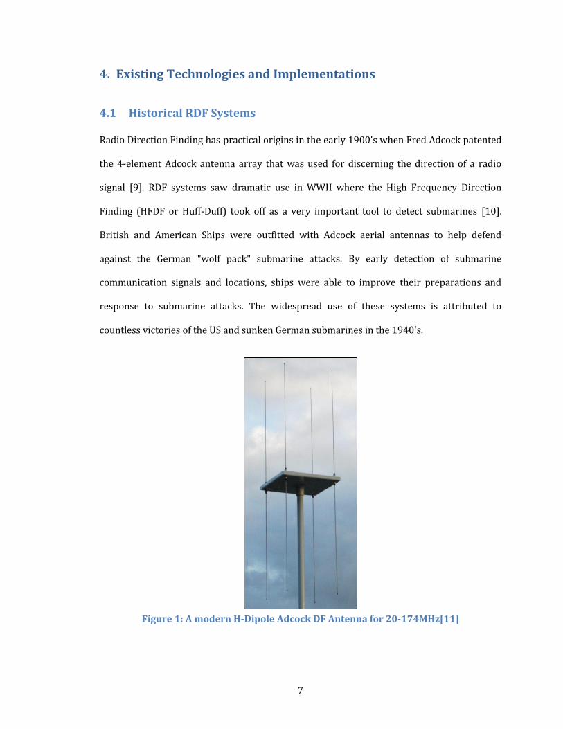
Radio Direction Finding has practical origins in the early 1900's when Fred Adcock patented
the 4-element Adcock antenna array that was used for discerning the direction of a radio
signal [9]. RDF systems saw dramatic use in WWII where the High Frequency Direction
Finding (HFDF or Huff-Duff) took off as a very important tool to detect submarines [10].
British and American Ships were outfitted with Adcock aerial antennas to help defend
against the German "wolf pack" submarine attacks. By early detection of submarine
communication signals and locations, ships were able to improve their preparations and
response to submarine attacks. The widespread use of these systems is attributed to
countless victories of the US and sunken German submarines in the 1940's.
Figure 1: A modern H-Dipole Adcock DF Antenna for 20-174MHz[11]
8
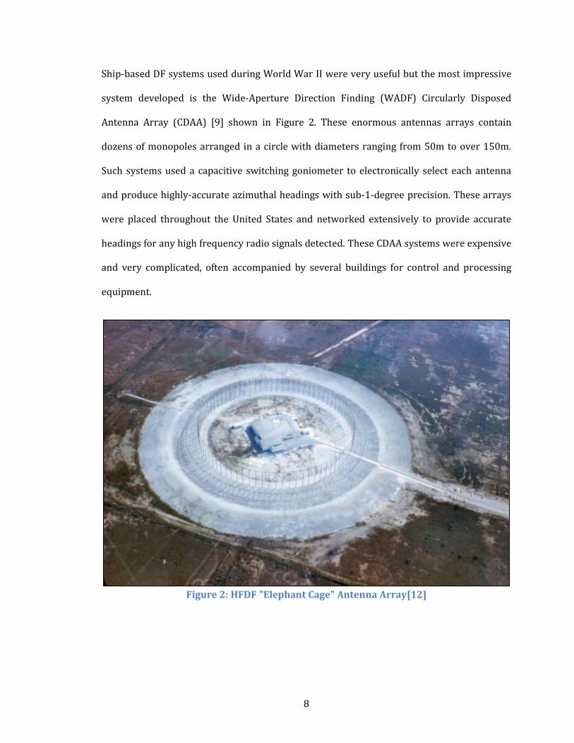
Ship-based DF systems used during World War II were very useful but the most impressive
system developed is the Wide-Aperture Direction Finding (WADF) Circularly Disposed
Antenna Array (CDAA) [9] shown in Figure 2. These enormous antennas arrays contain
dozens of monopoles arranged in a circle with diameters ranging from 50m to over 150m.
Such systems used a capacitive switching goniometer to electronically select each antenna
and produce highly-accurate azimuthal headings with sub-1-degree precision. These arrays
were placed throughout the United States and networked extensively to provide accurate
headings for any high frequency radio signals detected. These CDAA systems were expensive
and very complicated, often accompanied by several buildings for control and processing
equipment.
Figure 2: HFDF "Elephant Cage" Antenna Array[12]
9
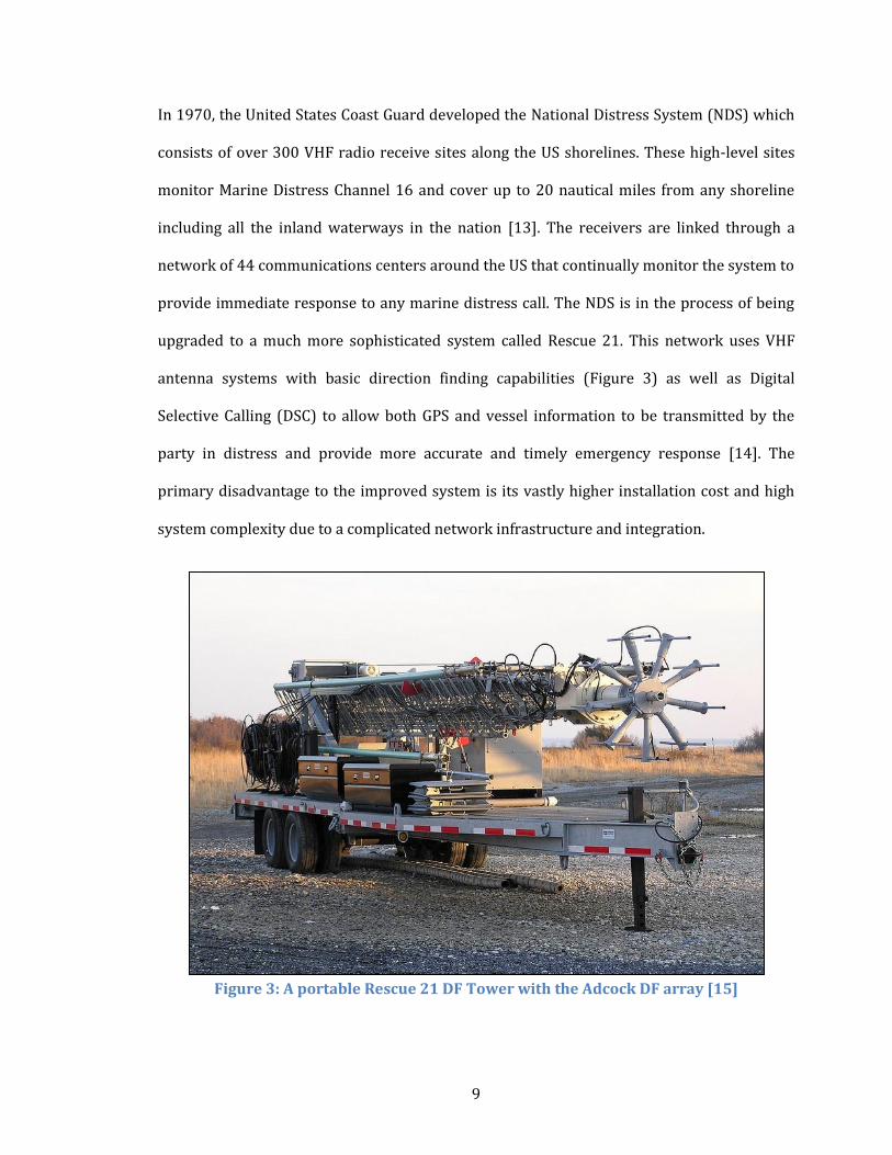
In 1970, the United States Coast Guard developed the National Distress System (NDS) which
consists of over 300 VHF radio receive sites along the US shorelines. These high-level sites
monitor Marine Distress Channel 16 and cover up to 20 nautical miles from any shoreline
including all the inland waterways in the nation [13]. The receivers are linked through a
network of 44 communications centers around the US that continually monitor the system to
provide immediate response to any marine distress call. The NDS is in the process of being
upgraded to a much more sophisticated system called Rescue 21. This network uses VHF
antenna systems with basic direction finding capabilities (Figure 3) as well as Digital
Selective Calling (DSC) to allow both GPS and vessel information to be transmitted by the
party in distress and provide more accurate and timely emergency response [14]. The
primary disadvantage to the improved system is its vastly higher installation cost and high
system complexity due to a complicated network infrastructure and integration.
Figure 3: A portable Rescue 21 DF Tower with the Adcock DF array [15]
10
4.2 Current RDF Applications
In this section, a number of existing RDF applications are introduced and characterized by
their DF methods and system topology.
4.2.1 Civil Air Patrol
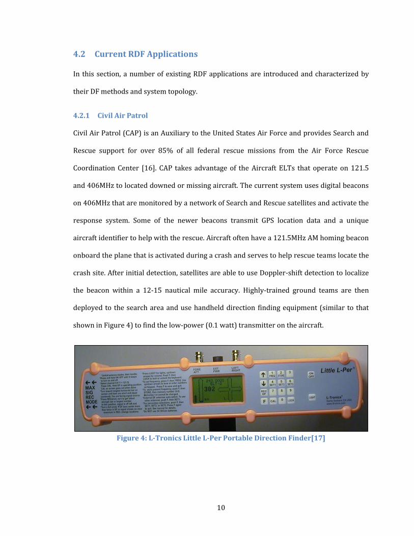
Civil Air Patrol (CAP) is an Auxiliary to the United States Air Force and provides Search and
Rescue support for over 85% of all federal rescue missions from the Air Force Rescue
Coordination Center [16]. CAP takes advantage of the Aircraft ELTs that operate on 121.5
and 406MHz to located downed or missing aircraft. The current system uses digital beacons
on 406MHz that are monitored by a network of Search and Rescue satellites and activate the
response system. Some of the newer beacons transmit GPS location data and a unique
aircraft identifier to help with the rescue. Aircraft often have a 121.5MHz AM homing beacon
onboard the plane that is activated during a crash and serves to help rescue teams locate the
crash site. After initial detection, satellites are able to use Doppler-shift detection to localize
the beacon within a 12-15 nautical mile accuracy. Highly-trained ground teams are then
deployed to the search area and use handheld direction finding equipment (similar to that
shown in Figure 4) to find the low-power (0.1 watt) transmitter on the aircraft.
Figure 4: L-Tronics Little L-Per Portable Direction Finder[17]
11
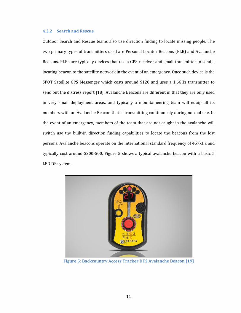
4.2.2 Search and Rescue
Outdoor Search and Rescue teams also use direction finding to locate missing people. The
two primary types of transmitters used are Personal Locator Beacons (PLB) and Avalanche
Beacons. PLBs are typically devices that use a GPS receiver and small transmitter to send a
locating beacon to the satellite network in the event of an emergency. Once such device is the
SPOT Satellite GPS Messenger which costs around $120 and uses a 1.6GHz transmitter to
send out the distress report [18]. Avalanche Beacons are different in that they are only used
in very small deployment areas, and typically a mountaineering team will equip all its
members with an Avalanche Beacon that is transmitting continuously during normal use. In
the event of an emergency, members of the team that are not caught in the avalanche will
switch use the built-in direction finding capabilities to locate the beacons from the lost
persons. Avalanche beacons operate on the international standard frequency of 457kHz and
typically cost around $200-500. Figure 5 shows a typical avalanche beacon with a basic 5
LED DF system.
Figure 5: Backcountry Access Tracker DTS Avalanche Beacon [19]

12
4.2.3 Wildlife Tracking
Researchers frequently use small radio transmitters for animal tracking to observe
migration patterns and other behaviors. Beacons used for animal tracking are extremely
diverse and cover a large range of sizes and transmitter output powers[20]. Figure 6 shows
one example of such a small transmitter on a bee.
Figure 6: A 170 milligram radio tracking tag on a bee [21]
Typical radio frequencies for wildlife tracking are from 30-400MHz [20]. The VHF band is
the most commonly used for these applications and typical receiver systems use a
directional antenna (Figure 7) for manual signal-strength direction finding.
Figure 7: A manual VHF direction finding antenna system for wildlife tracking [22]
13
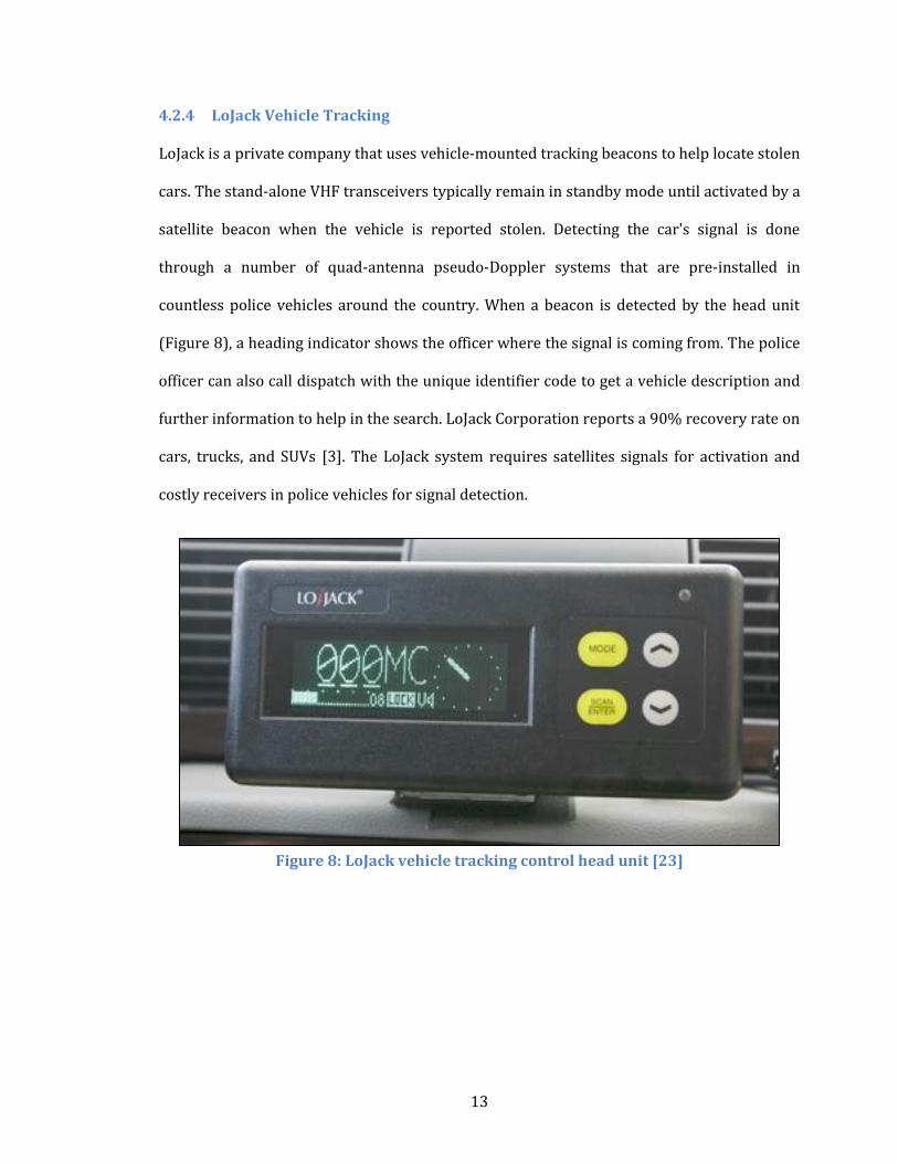
4.2.4 LoJack Vehicle Tracking
LoJack is a private company that uses vehicle-mounted tracking beacons to help locate stolen
cars. The stand-alone VHF transceivers typically remain in standby mode until activated by a
satellite beacon when the vehicle is reported stolen. Detecting the car's signal is done
through a number of quad-antenna pseudo-Doppler systems that are pre-installed in
countless police vehicles around the country. When a beacon is detected by the head unit
(Figure 8), a heading indicator shows the officer where the signal is coming from. The police
officer can also call dispatch with the unique identifier code to get a vehicle description and
further information to help in the search. LoJack Corporation reports a 90% recovery rate on
cars, trucks, and SUVs [3]. The LoJack system requires satellites signals for activation and
costly receivers in police vehicles for signal detection.
Figure 8: LoJack vehicle tracking control head unit [23]
14
4.2.5 Wireless E911 Phase 2
Wireless E911 is a Federal Communications Commission (FCC) mandate from 2010 that
requires cellular phone companies to provide location data for the origin of an emergency
call to the appropriate 911 call center [24]. The initial phase of this mandate required that
95% of a provider's in-service phones must provide locating capabilities by December 31,
2005. E911 Phase II required that cell phone location could be determined to 50-300m
accuracy when requested by a Public Safety Answering Point (PSAP) [25]. Cellular providers
use a variety of locating techniques including A-GPS (Assisted GPS), U-TDOA (Uplink Time
Difference of Arrival), AOA (Angle of Arrival), and E-OTD (Enhanced Observed Time
Difference). The most common of these is U-TDOA which measures the precise arrival of a
cellular signal at various network base stations to determine the device's location. U-TDOA
takes advantage of existing multi-billion dollar infrastructure of cell phone towers and vast
computing backbone to provide both the sensing and processing required for accurate
location reporting. TruePosition is an example of several companies that provide location
services for cellular carriers. TruePosition uses several locating technologies including U-
TDOA, AOA, and a Hybrid Location Solution to develop a robust cellular locating network
[26]. The primary disadvantage to these E911 systems is their dependence on elaborate
existing hardware from the cellular industry. Cellular infrastructure is also unstable and
prone to premature failure in disaster situations when systems become overloaded and
power outages cause towers to go out of service [27]. Rural public service applications would
require enormous installation costs to establish an equivalent infrastructure.

15
5. Problem Refinement and Scope
The following list provides subjective metrics for each RDFN in order to characterize the
existing systems and provide a basis for comparison between them.
Rescue 21
o Cost: HIGH, Complexity: HIGH
o Network Implementation: Costal Networked Tower Sites
o RDF Method: 9-element Adcock Array, AOA [27]
o Disadvantages: Large, complex, and expensive.
Aircraft ELT System
o Cost: MED, Complexity: HIGH
o Network Implementation: Satellite and Aircraft Monitoring
o RDF Method: Satellite and manual ground team direction finding
o Disadvantages: Satellite dependency, high failure rate
Avalanche Beacons
o Cost: LOW, Complexity: MED
o Network Implementation: None.
o RDF Method: Manual ground team direction finding
o Disadvantages: Requires skilled DF rescuer, small-area coverage
Personal Locating Beacons
o Cost: LOW, Complexity: MED/HIGH
o Network Implementation: None.
o RDF Method: GPS Position Reporting
o Disadvantages: Satellite dependency and additional hardware needed
Wildlife Tracking
o Cost: LOW, Complexity: MED
o Network Implementation: None.
o RDF Method: Manual ground team direction finding
o Disadvantages: Requires skilled DF operator, small-area coverage
LoJack
o Cost: MED, Complexity: HIGH
o Network Implementation: Satellite and vehicle based receivers
o RDF Method: Pseudo-Doppler
o Disadvantages: Satellite dependency and cost
E911
o Cost: HIGH, Complexity: HIGH
o Network Implementation: Existing cell tower sites
o RDF Method: U-TDOA, AOA, E-OTD
o Disadvantages: High cost and dependence on infrastructure
16
A thorough examination of all the existing RDF systems explored in 4.2 quickly reveals that
all are either large-scale and high-cost (e.g. Rescue 21) or small-scale and very specialized
implementations of an RDF system (e.g. wildlife tracking). The missing link between nation-
wide RDFNs and portable, handheld DF device's lies in a deployable RDFN that is available at
a much lower cost than current networks and that has a much simpler architecture. Having a
lost-cost, deployable VHF RDF network for public service and emergency response is the
next step in enabling dozens of organizations to better manage their response and safety in
an emergency.
This project focuses on finding an RDF solution that addresses the two major roadblocks of
widespread RDFN use: cost and complexity. (Note that for the remainder of the document
cost and complexity will be italicized when present.) For example, the total Rescue 21 system
cost was estimated at $872 million (increased from the initial acquisition cost in 1999 of
$250 million [28]) showing that large-scale RDFNs are extremely expensive. One of the
primary objectives of this project is to minimize system cost to increase the availability of
this technology to end users. The second major task is in system complexity both from an
equipment and usability perspective. Existing RDF systems either have complex equipment
requirements that greatly increase total cost (e.g. E911 and LoJack) or they have simple
equipment but require highly skilled operators to locate them (e.g. wildlife tracking and
avalanche beacons). In order to address these issues, the proposed system must maintain a
simple hardware implementation and an accessible end user experience, while keeping
expenses to a minimum.
Given the designated end user and additional system limitations, the following list of desired
system characteristics is developed.
17
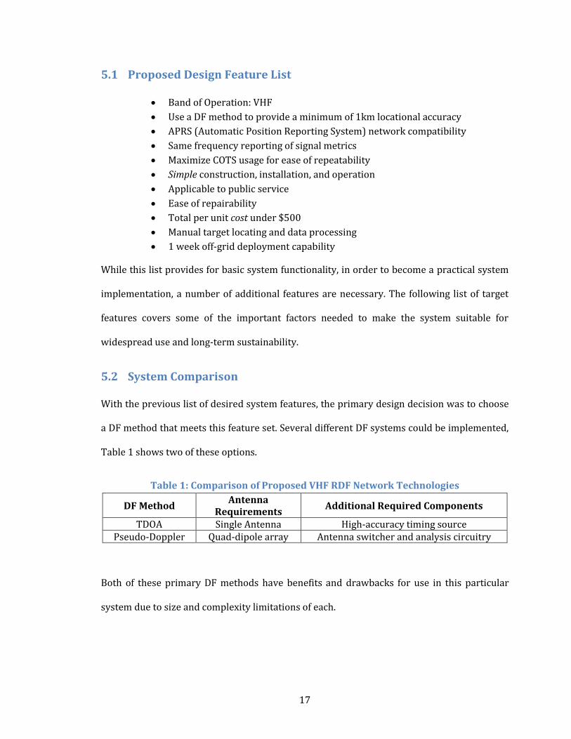
5.1 Proposed Design Feature List
Band of Operation: VHF
Use a DF method to provide a minimum of 1km locational accuracy
APRS (Automatic Position Reporting System) network compatibility
Same frequency reporting of signal metrics
Maximize COTS usage for ease of repeatability
Simple construction, installation, and operation
Applicable to public service
Ease of repairability
Total per unit cost under $500
Manual target locating and data processing
1 week off-grid deployment capability
While this list provides for basic system functionality, in order to become a practical system
implementation, a number of additional features are necessary. The following list of target
features covers some of the important factors needed to make the system suitable for
widespread use and long-term sustainability.
5.2 System Comparison
With the previous list of desired system features, the primary design decision was to choose
a DF method that meets this feature set. Several different DF systems could be implemented,
Table 1 shows two of these options.
Table 1: Comparison of Proposed VHF RDF Network Technologies
DF Method Antenna
Requirements Additional Required Components
TDOA Single Antenna High-accuracy timing source Pseudo-Doppler Quad-dipole array Antenna switcher and analysis circuitry
Both of these primary DF methods have benefits and drawbacks for use in this particular
system due to size and complexity limitations of each.
18
5.2.1 TDOA
The TDOA system has the simplest hardware, but has a significant technical constraint
requiring a highly accurate timing source for accurate direction finding. Another drawback of
the TDOA system is that no directional information is given from the signal metrics. This
requires at least 3 receivers to provide signal data in order for any locating to be successful.
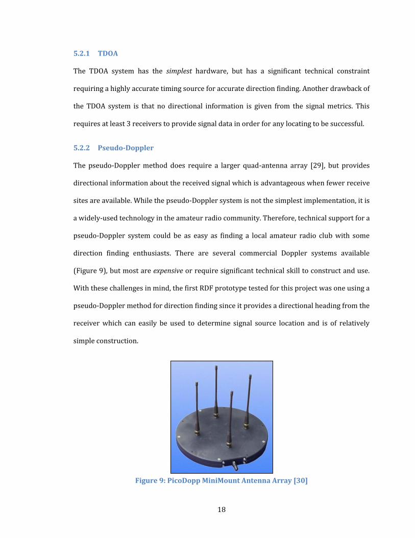
5.2.2 Pseudo-Doppler
The pseudo-Doppler method does require a larger quad-antenna array [29], but provides
directional information about the received signal which is advantageous when fewer receive
sites are available. While the pseudo-Doppler system is not the simplest implementation, it is
a widely-used technology in the amateur radio community. Therefore, technical support for a
pseudo-Doppler system could be as easy as finding a local amateur radio club with some
direction finding enthusiasts. There are several commercial Doppler systems available
(Figure 9), but most are expensive or require significant technical skill to construct and use.
With these challenges in mind, the first RDF prototype tested for this project was one using a
pseudo-Doppler method for direction finding since it provides a directional heading from the
receiver which can easily be used to determine signal source location and is of relatively
simple construction.
Figure 9: PicoDopp MiniMount Antenna Array [30]
19
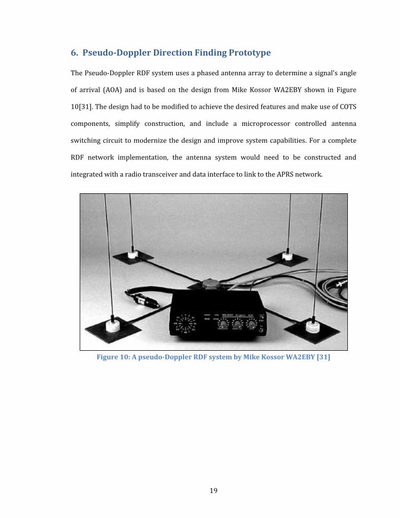
6. Pseudo-Doppler Direction Finding Prototype
The Pseudo-Doppler RDF system uses a phased antenna array to determine a signal's angle
of arrival (AOA) and is based on the design from Mike Kossor WA2EBY shown in Figure
10[31]. The design had to be modified to achieve the desired features and make use of COTS
components, simplify construction, and include a microprocessor controlled antenna
switching circuit to modernize the design and improve system capabilities. For a complete
RDF network implementation, the antenna system would need to be constructed and
integrated with a radio transceiver and data interface to link to the APRS network.
Figure 10: A pseudo-Doppler RDF system by Mike Kossor WA2EBY [31]
20
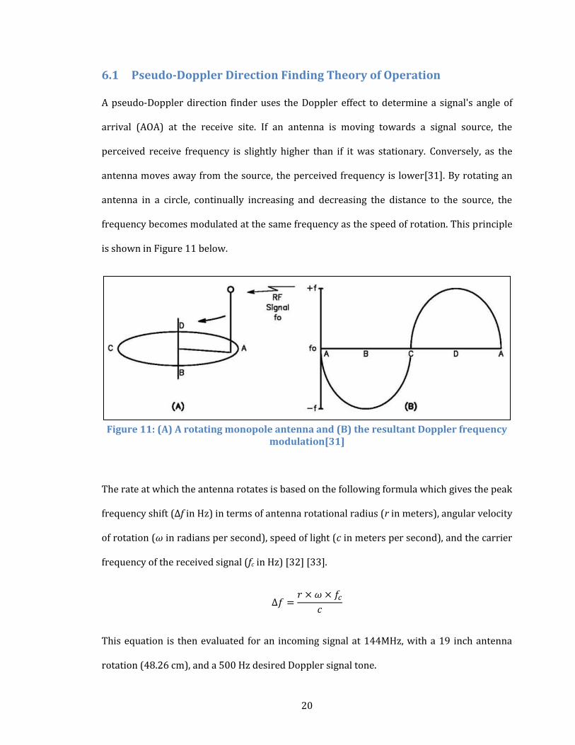
6.1 Pseudo-Doppler Direction Finding Theory of Operation
A pseudo-Doppler direction finder uses the Doppler effect to determine a signal's angle of
arrival (AOA) at the receive site. If an antenna is moving towards a signal source, the
perceived receive frequency is slightly higher than if it was stationary. Conversely, as the
antenna moves away from the source, the perceived frequency is lower[31]. By rotating an
antenna in a circle, continually increasing and decreasing the distance to the source, the
frequency becomes modulated at the same frequency as the speed of rotation. This principle
is shown in Figure 11 below.
Figure 11: (A) A rotating monopole antenna and (B) the resultant Doppler frequency
modulation[31]
The rate at which the antenna rotates is based on the following formula which gives the peak
frequency shift (Δf in Hz) in terms of antenna rotational radius (r in meters), angular velocity
of rotation (ω in radians per second), speed of light (c in meters per second), and the carrier
frequency of the received signal (fc in Hz) [32] [33].
This equation is then evaluated for an incoming signal at 144MHz, with a 19 inch antenna
rotation (48.26 cm), and a 500 Hz desired Doppler signal tone.
21
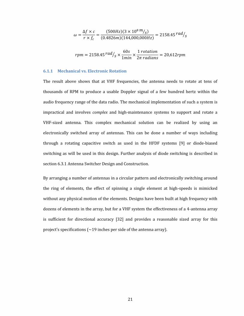
6.1.1 Mechanical vs. Electronic Rotation
The result above shows that at VHF frequencies, the antenna needs to rotate at tens of
thousands of RPM to produce a usable Doppler signal of a few hundred hertz within the
audio frequency range of the data radio. The mechanical implementation of such a system is
impractical and involves complex and high-maintenance systems to support and rotate a
VHF-sized antenna. This complex mechanical solution can be realized by using an
electronically switched array of antennas. This can be done a number of ways including
through a rotating capacitive switch as used in the HFDF systems [9] or diode-biased
switching as will be used in this design. Further analysis of diode switching is described in
section 6.3.1 Antenna Switcher Design and Construction.
By arranging a number of antennas in a circular pattern and electronically switching around
the ring of elements, the effect of spinning a single element at high-speeds is mimicked
without any physical motion of the elements. Designs have been built at high frequency with
dozens of elements in the array, but for a VHF system the effectiveness of a 4-antenna array
is sufficient for directional accuracy [32] and provides a reasonable sized array for this
project's specifications (~19 inches per side of the antenna array).
22
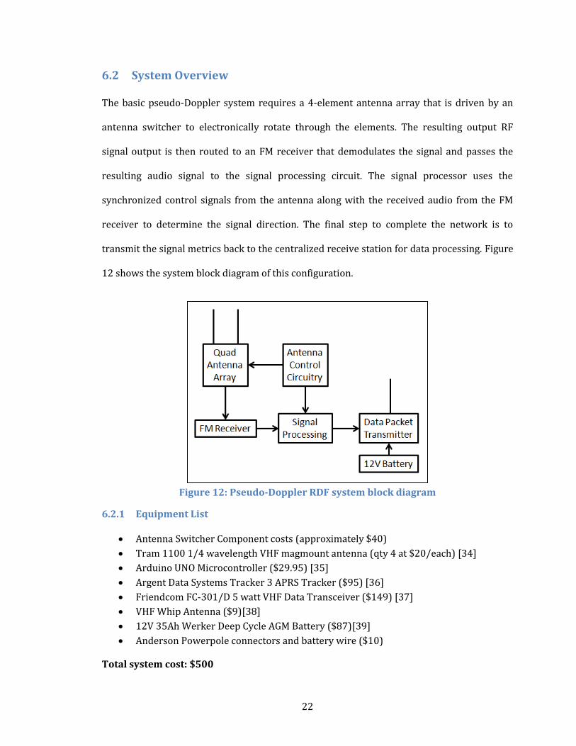
6.2 System Overview
The basic pseudo-Doppler system requires a 4-element antenna array that is driven by an
antenna switcher to electronically rotate through the elements. The resulting output RF
signal output is then routed to an FM receiver that demodulates the signal and passes the
resulting audio signal to the signal processing circuit. The signal processor uses the
synchronized control signals from the antenna along with the received audio from the FM
receiver to determine the signal direction. The final step to complete the network is to
transmit the signal metrics back to the centralized receive station for data processing. Figure
12 shows the system block diagram of this configuration.
Figure 12: Pseudo-Doppler RDF system block diagram
6.2.1 Equipment List
Antenna Switcher Component costs (approximately $40)
Tram 1100 1/4 wavelength VHF magmount antenna (qty 4 at $20/each) [34]
Arduino UNO Microcontroller ($29.95) [35]
Argent Data Systems Tracker 3 APRS Tracker ($95) [36]
Friendcom FC-301/D 5 watt VHF Data Transceiver ($149) [37]
VHF Whip Antenna ($9)[38]
12V 35Ah Werker Deep Cycle AGM Battery ($87)[39]
Anderson Powerpole connectors and battery wire ($10)
Total system cost: $500
23
6.3 System Design Modification and Construction
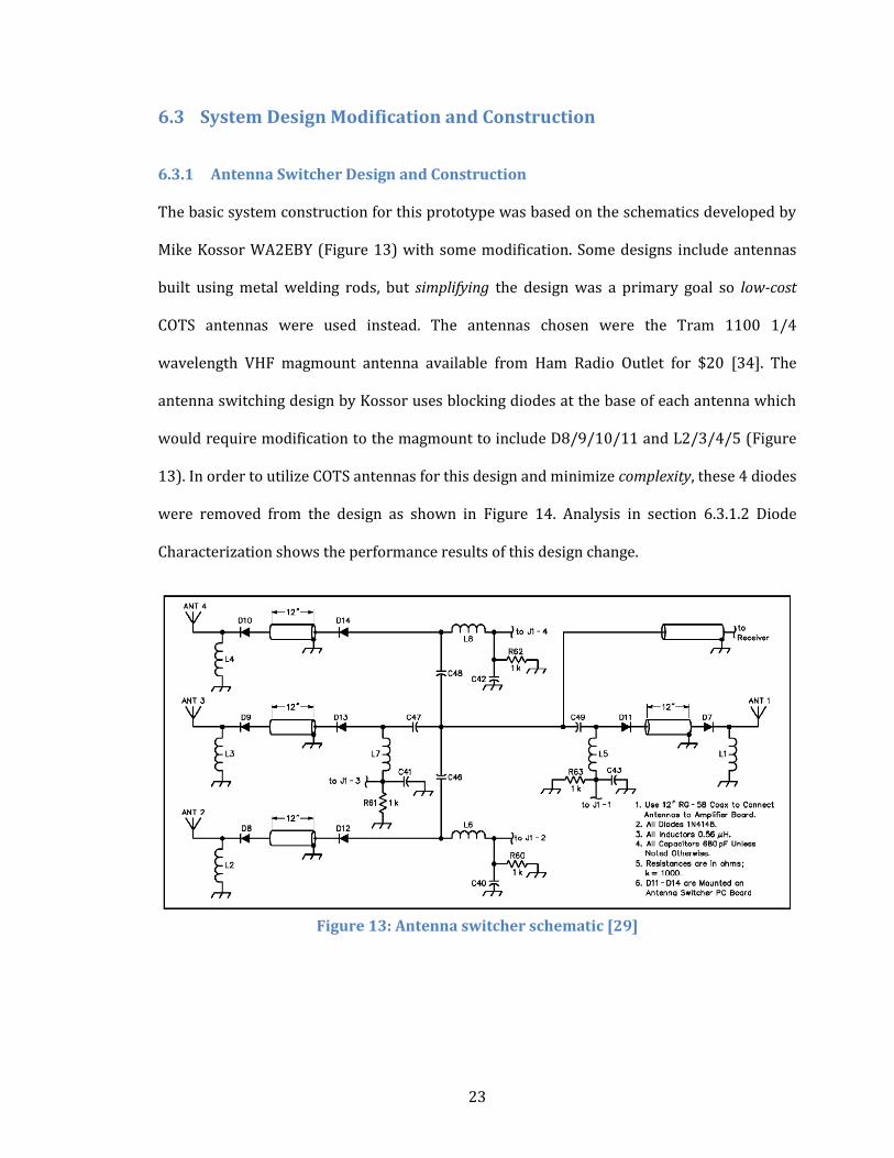
6.3.1 Antenna Switcher Design and Construction
The basic system construction for this prototype was based on the schematics developed by
Mike Kossor WA2EBY (Figure 13) with some modification. Some designs include antennas
built using metal welding rods, but simplifying the design was a primary goal so low-cost
COTS antennas were used instead. The antennas chosen were the Tram 1100 1/4
wavelength VHF magmount antenna available from Ham Radio Outlet for $20 [34]. The
antenna switching design by Kossor uses blocking diodes at the base of each antenna which
would require modification to the magmount to include D8/9/10/11 and L2/3/4/5 (Figure
13). In order to utilize COTS antennas for this design and minimize complexity, these 4 diodes
were removed from the design as shown in Figure 14. Analysis in section 6.3.1.2 Diode
Characterization shows the performance results of this design change.
Figure 13: Antenna switcher schematic [29]
24
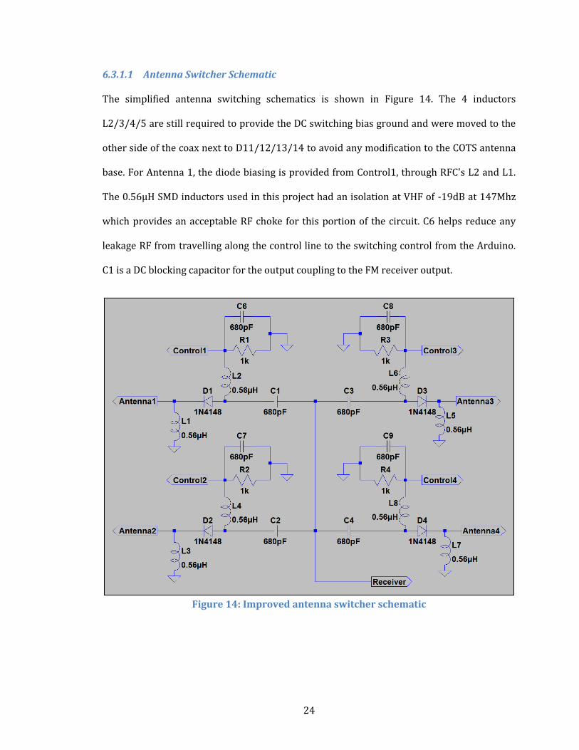
6.3.1.1 Antenna Switcher Schematic
The simplified antenna switching schematics is shown in Figure 14. The 4 inductors
L2/3/4/5 are still required to provide the DC switching bias ground and were moved to the
other side of the coax next to D11/12/13/14 to avoid any modification to the COTS antenna
base. For Antenna 1, the diode biasing is provided from Control1, through RFC's L2 and L1.
The 0.56µH SMD inductors used in this project had an isolation at VHF of -19dB at 147Mhz
which provides an acceptable RF choke for this portion of the circuit. C6 helps reduce any
leakage RF from travelling along the control line to the switching control from the Arduino.
C1 is a DC blocking capacitor for the output coupling to the FM receiver output.
Figure 14: Improved antenna switcher schematic
25
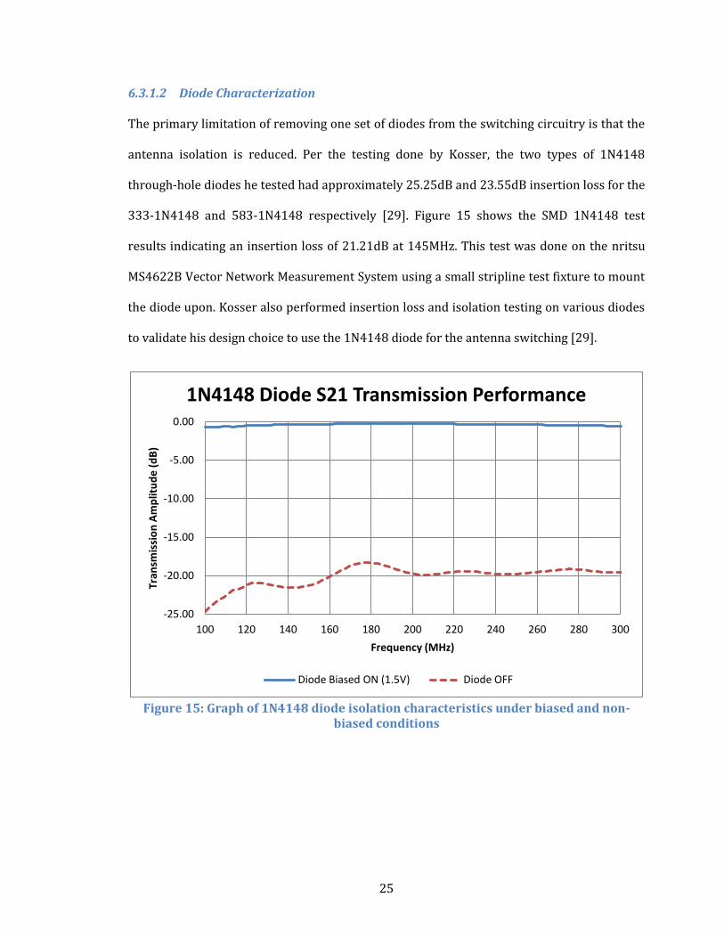
6.3.1.2 Diode Characterization
The primary limitation of removing one set of diodes from the switching circuitry is that the
antenna isolation is reduced. Per the testing done by Kosser, the two types of 1N4148
through-hole diodes he tested had approximately 25.25dB and 23.55dB insertion loss for the
333-1N4148 and 583-1N4148 respectively [29]. Figure 15 shows the SMD 1N4148 test
results indicating an insertion loss of 21.21dB at 145MHz. This test was done on the nritsu
MS4622B Vector Network Measurement System using a small stripline test fixture to mount
the diode upon. Kosser also performed insertion loss and isolation testing on various diodes
to validate his design choice to use the 1N4148 diode for the antenna switching [29].
Figure 15: Graph of 1N4148 diode isolation characteristics under biased and non-
biased conditions
-25.00
-20.00
-15.00
-10.00
-5.00
0.00
100 120 140 160 180 200 220 240 260 280 300
Tran
smis
sio
n A
mp
litu
de
(d
B)
Frequency (MHz)
1N4148 Diode S21 Transmission Performance
Diode Biased ON (1.5V) Diode OFF
26
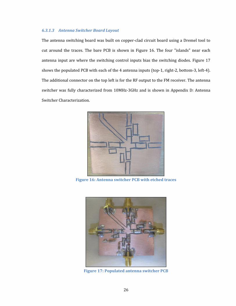
6.3.1.3 Antenna Switcher Board Layout
The antenna switching board was built on copper-clad circuit board using a Dremel tool to
cut around the traces. The bare PCB is shown in Figure 16. The four "islands" near each
antenna input are where the switching control inputs bias the switching diodes. Figure 17
shows the populated PCB with each of the 4 antenna inputs (top-1, right-2, bottom-3, left-4).
The additional connector on the top left is for the RF output to the FM receiver. The antenna
switcher was fully characterized from 10MHz-3GHz and is shown in Appendix D: Antenna
Switcher Characterization.
Figure 16: Antenna switcher PCB with etched traces
Figure 17: Populated antenna switcher PCB
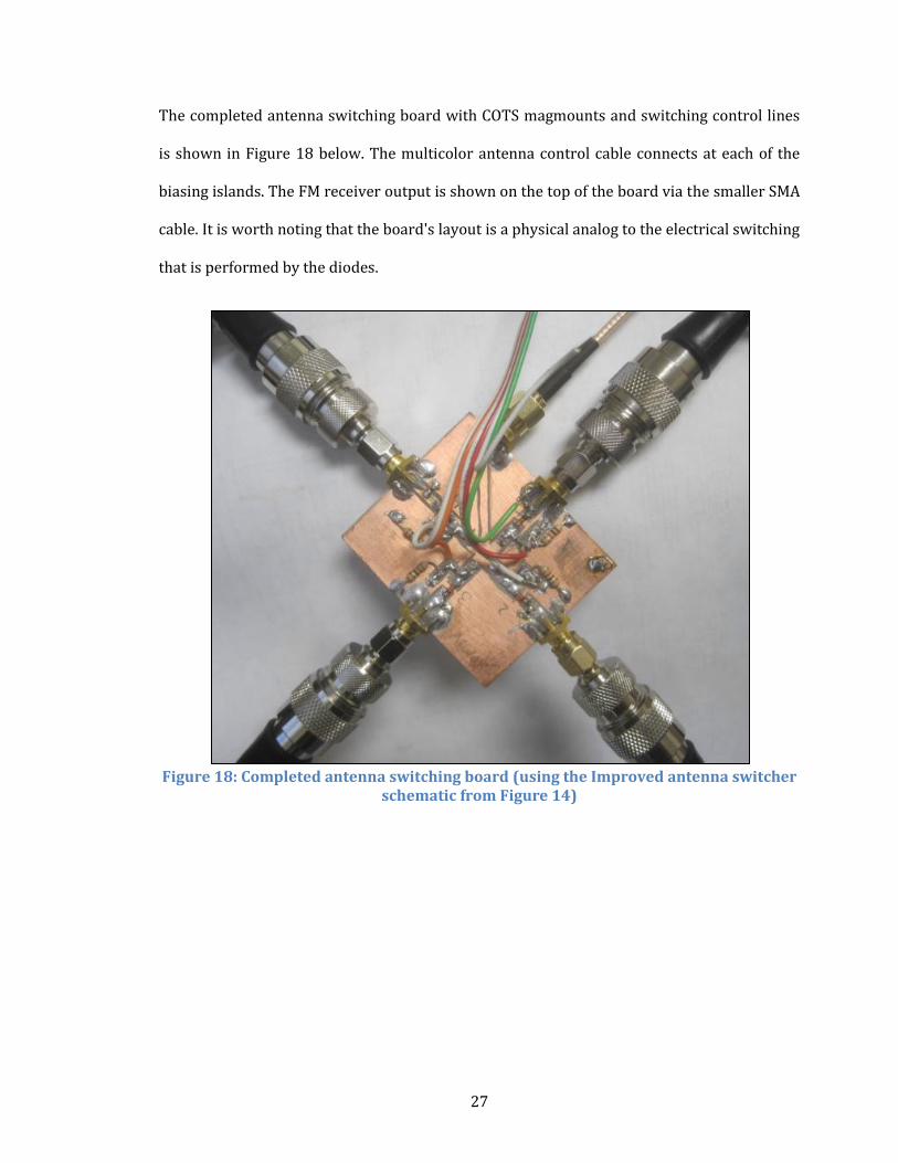
27
The completed antenna switching board with COTS magmounts and switching control lines
is shown in Figure 18 below. The multicolor antenna control cable connects at each of the
biasing islands. The FM receiver output is shown on the top of the board via the smaller SMA
cable. It is worth noting that the board's layout is a physical analog to the electrical switching
that is performed by the diodes.
Figure 18: Completed antenna switching board (using the Improved antenna switcher
schematic from Figure 14)
28
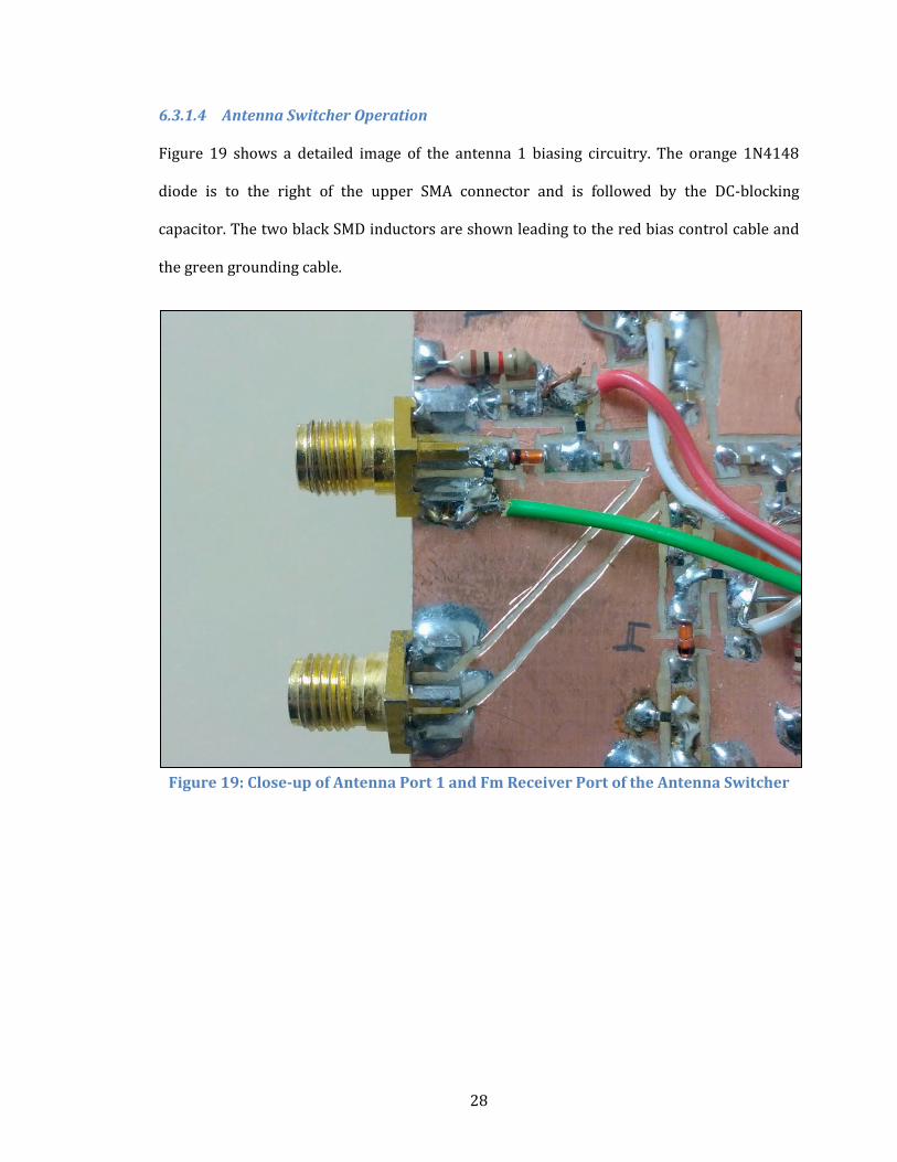
6.3.1.4 Antenna Switcher Operation
Figure 19 shows a detailed image of the antenna 1 biasing circuitry. The orange 1N4148
diode is to the right of the upper SMA connector and is followed by the DC-blocking
capacitor. The two black SMD inductors are shown leading to the red bias control cable and
the green grounding cable.
Figure 19: Close-up of Antenna Port 1 and Fm Receiver Port of the Antenna Switcher
29
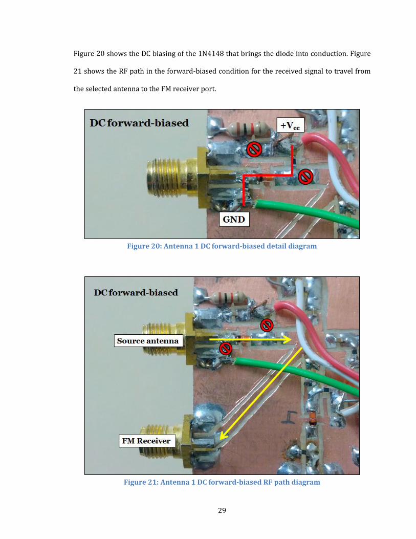
Figure 20 shows the DC biasing of the 1N4148 that brings the diode into conduction. Figure
21 shows the RF path in the forward-biased condition for the received signal to travel from
the selected antenna to the FM receiver port.
Figure 20: Antenna 1 DC forward-biased detail diagram
Figure 21: Antenna 1 DC forward-biased RF path diagram
30
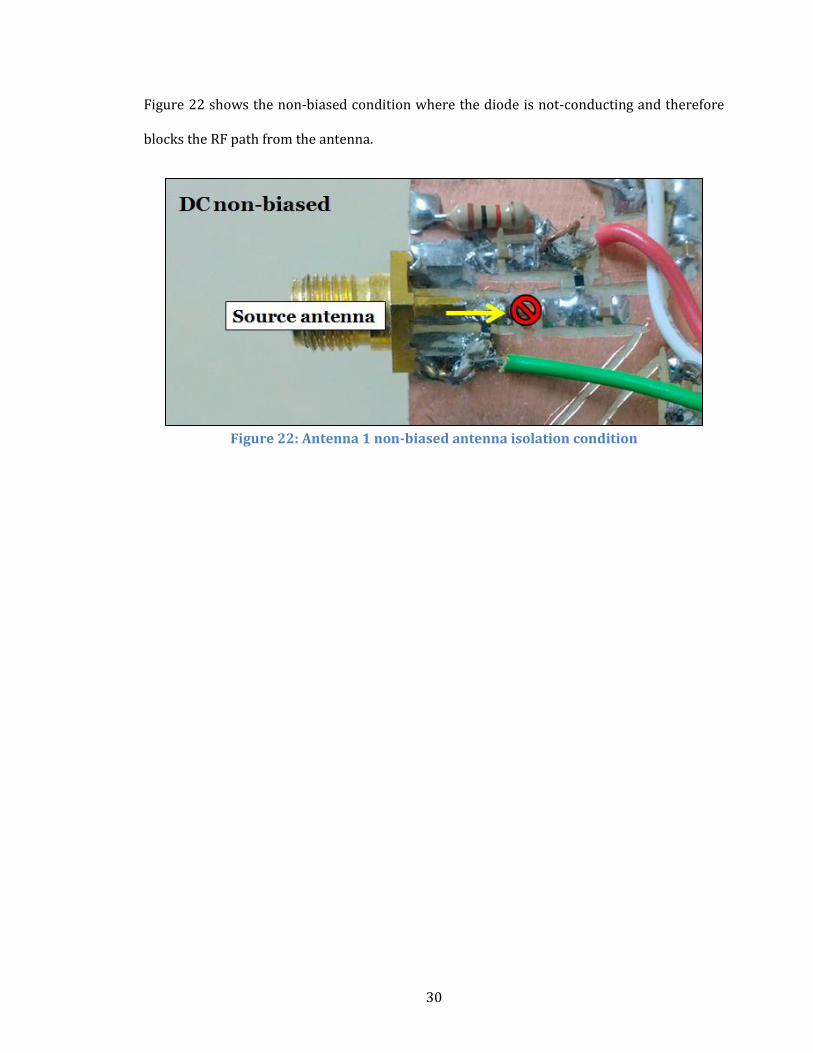
Figure 22 shows the non-biased condition where the diode is not-conducting and therefore
blocks the RF path from the antenna.
Figure 22: Antenna 1 non-biased antenna isolation condition
31
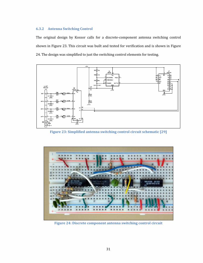
6.3.2 Antenna Switching Control
The original design by Kossor calls for a discrete-component antenna switching control
shown in Figure 23. This circuit was built and tested for verification and is shown in Figure
24. The design was simplified to just the switching control elements for testing.
Figure 23: Simplified antenna switching control circuit schematic [29]
Figure 24: Discrete component antenna switching control circuit
32
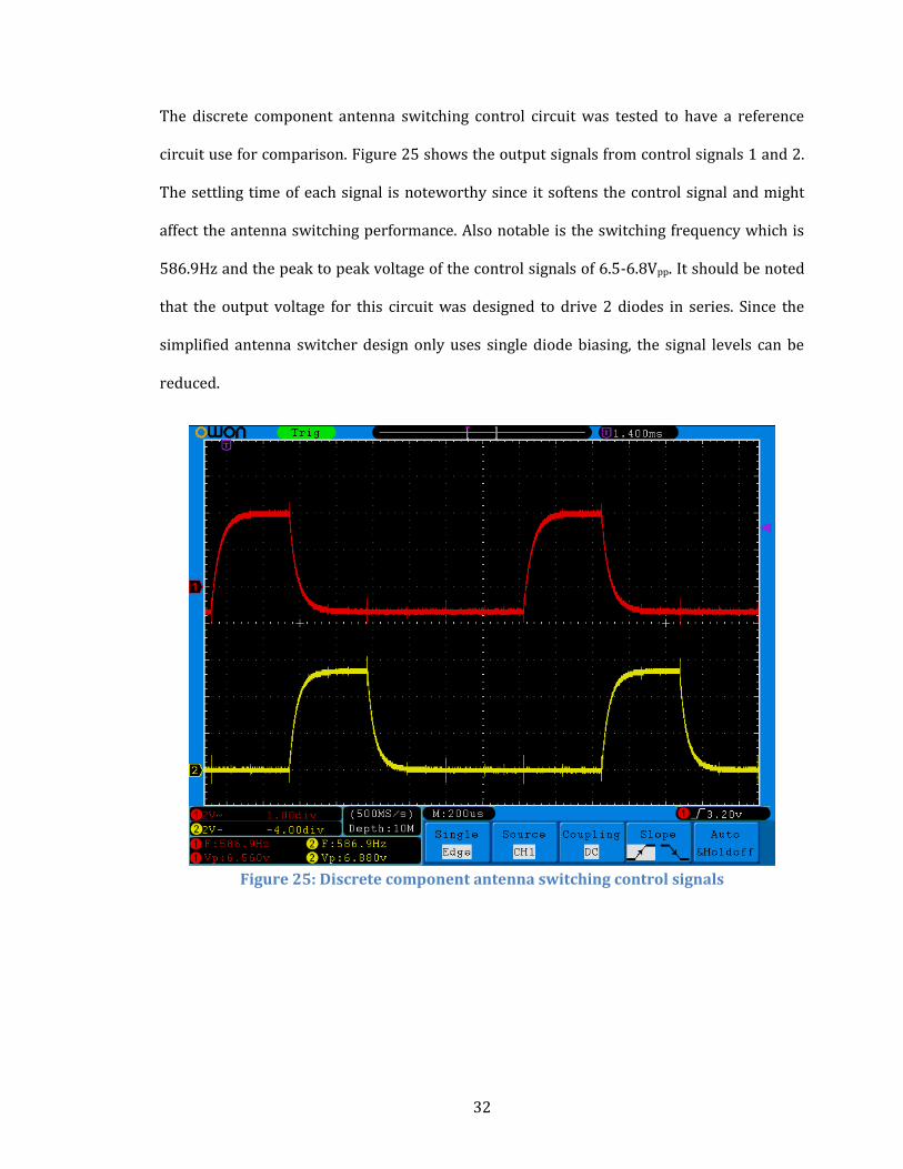
The discrete component antenna switching control circuit was tested to have a reference
circuit use for comparison. Figure 25 shows the output signals from control signals 1 and 2.
The settling time of each signal is noteworthy since it softens the control signal and might
affect the antenna switching performance. Also notable is the switching frequency which is
586.9Hz and the peak to peak voltage of the control signals of 6.5-6.8Vpp. It should be noted
that the output voltage for this circuit was designed to drive 2 diodes in series. Since the
simplified antenna switcher design only uses single diode biasing, the signal levels can be
reduced.
Figure 25: Discrete component antenna switching control signals
33
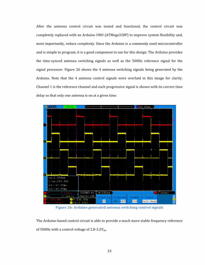
After the antenna control circuit was tested and functional, the control circuit was
completely replaced with an Arduino UNO (ATMega328P) to improve system flexibility and,
most importantly, reduce complexity. Since the Arduino is a commonly used microcontroller
and is simple to program, it is a good component to use for this design. The Arduino provides
the time-synced antenna switching signals as well as the 500Hz reference signal for the
signal processor. Figure 26 shows the 4 antenna switching signals being generated by the
Arduino. Note that the 4 antenna control signals were overlaid in this image for clarity.
Channel 1 is the reference channel and each progressive signal is shown with its correct time
delay so that only one antenna is on at a given time.
Figure 26: Arduino generated antenna switching control signals
The Arduino-based control circuit is able to provide a much more stable frequency reference
of 500Hz with a control voltage of 2.8-3.2Vpp.
34
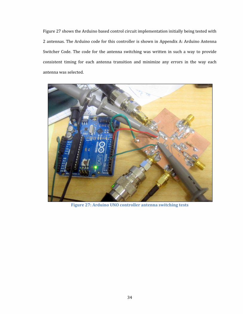
Figure 27 shows the Arduino based control circuit implementation initially being tested with
2 antennas. The Arduino code for this controller is shown in Appendix A: Arduino Antenna
Switcher Code. The code for the antenna switching was written in such a way to provide
consistent timing for each antenna transition and minimize any errors in the way each
antenna was selected.
Figure 27: Arduino UNO controller antenna switching tests
35
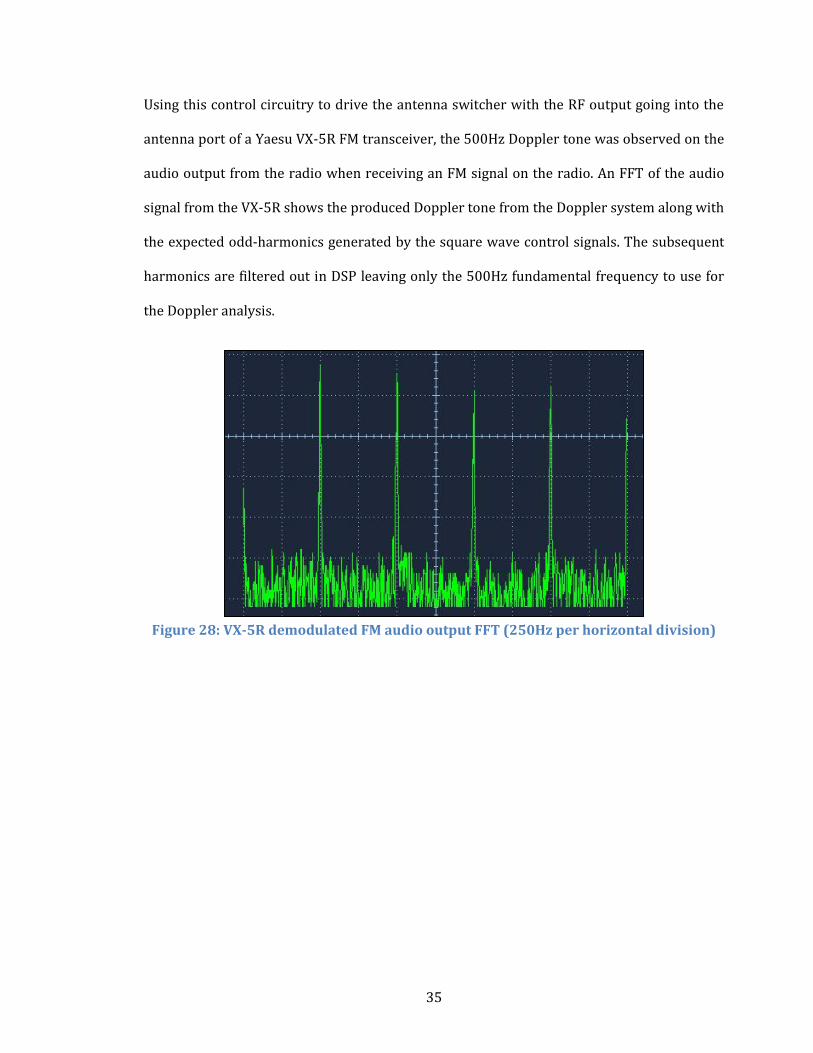
Using this control circuitry to drive the antenna switcher with the RF output going into the
antenna port of a Yaesu VX-5R FM transceiver, the 500Hz Doppler tone was observed on the
audio output from the radio when receiving an FM signal on the radio. An FFT of the audio
signal from the VX-5R shows the produced Doppler tone from the Doppler system along with
the expected odd-harmonics generated by the square wave control signals. The subsequent
harmonics are filtered out in DSP leaving only the 500Hz fundamental frequency to use for
the Doppler analysis.
Figure 28: VX-5R demodulated FM audio output FFT (250Hz per horizontal division)
36
6.4 Pseudo-Doppler RDF System Setup and Testing
In the completed receiver system, signal processing would be implemented in the Arduino or
a similar microcontroller to keep the system compact and simple. For the purposes of testing
the pseudo-Doppler RDF receiver, the SoundDoppler V1.20 software developed by Lodewijk
Baars PA3BNX was used to perform the signal analysis [40] [41]. This software implements
the filtering and frequency comparison of the Doppler system using DSP and provides a
simple visual output display of the measured direction heading of the received RF signal.
Very simple controls are also provided to calibrate the system and synchronize the switching
and audio signals. This program requires the switching reference frequency to be input on
the left channel of the computer's soundcard input and the demodulated FM audio from the
receiver on the right channel. This was easily accomplished using a simple audio adapter
board developed by Justin Kenny KJ6KST [42] to patch the Arduino reference frequency
output and the audio output from the Yaesu VX-5R (and FT-60R) used in these tests. The
netbook computer used for this test does not include a line-in port so a 30dB audio pad
previously built by the author was required to bring the line-level audio to mic-levels for the
software to use and prevent overdriving the computer's audio input circuitry. The complete
test system consisted of: 4 magmount antennas, antenna switcher PCB, Arduino UNO, 30dB
line-level adapter, audio patch board, FM radio transceiver, and netbook computer as shown
in Figure 29.
37
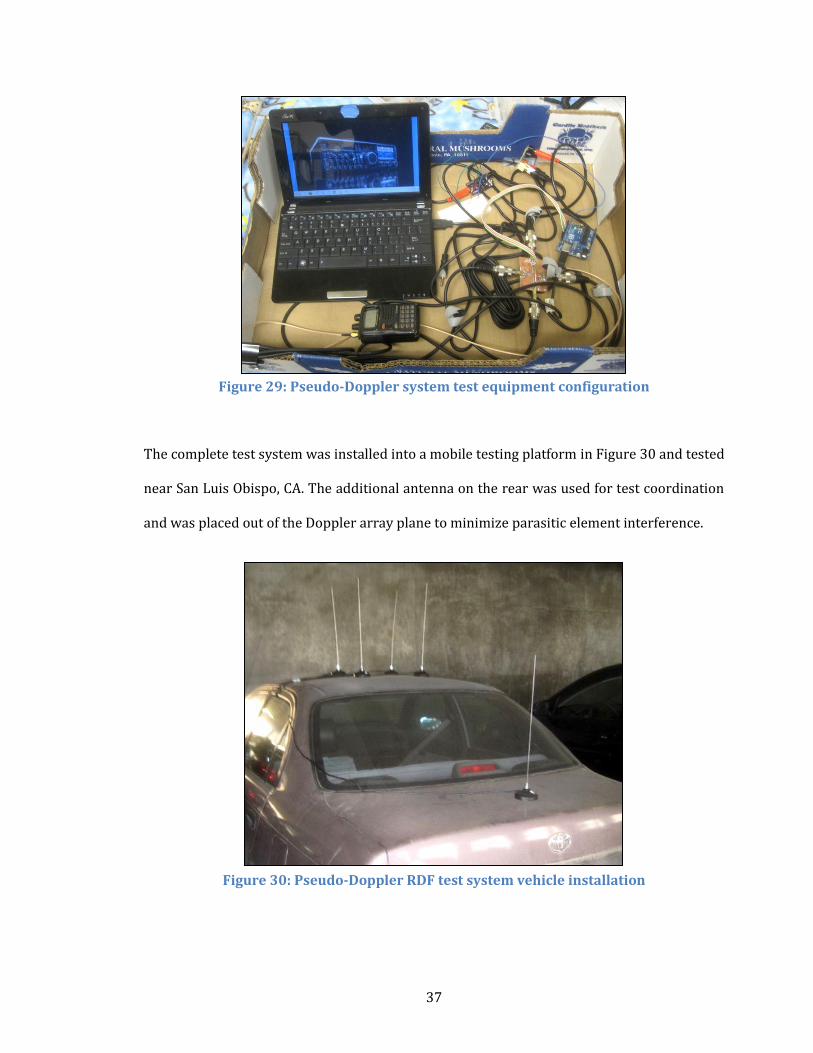
Figure 29: Pseudo-Doppler system test equipment configuration
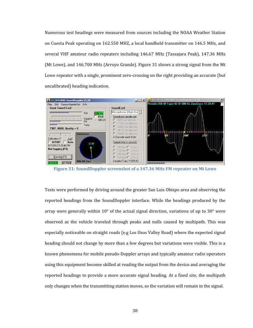
The complete test system was installed into a mobile testing platform in Figure 30 and tested
near San Luis Obispo, CA. The additional antenna on the rear was used for test coordination
and was placed out of the Doppler array plane to minimize parasitic element interference.
Figure 30: Pseudo-Doppler RDF test system vehicle installation
38
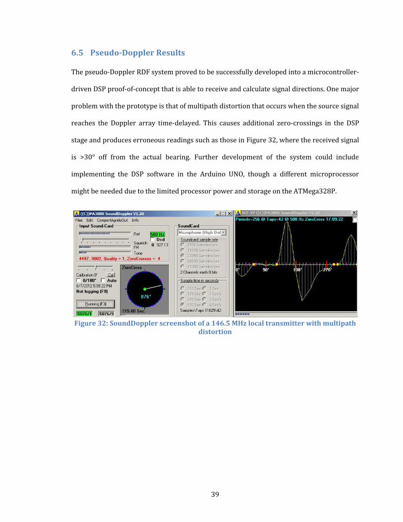
Numerous test headings were measured from sources including the NOAA Weather Station
on Cuesta Peak operating on 162.550 MHZ, a local handheld transmitter on 146.5 MHz, and
several VHF amateur radio repeaters including 146.67 MHz (Tassajara Peak), 147.36 MHz
(Mt Lowe), and 146.700 MHz (Arroyo Grande). Figure 31 shows a strong signal from the Mt
Lowe repeater with a single, prominent zero-crossing on the right providing an accurate (but
uncalibrated) heading indication.
Figure 31: SoundDoppler screenshot of a 147.36 MHz FM repeater on Mt Lowe
Tests were performed by driving around the greater San Luis Obispo area and observing the
reported headings from the SoundDoppler interface. While the headings produced by the
array were generally within 10° of the actual signal direction, variations of up to 30° were
observed as the vehicle traveled through peaks and nulls caused by multipath. This was
especially noticeable on straight roads (e.g Los Osos Valley Road) where the expected signal
heading should not change by more than a few degrees but variations were visible. This is a
known phenomena for mobile pseudo-Doppler arrays and typically amateur radio operators
using this equipment become skilled at reading the output from the device and averaging the
reported headings to provide a more accurate signal heading. At a fixed site, the multipath
only changes when the transmitting station moves, so the variation will remain in the signal.
39
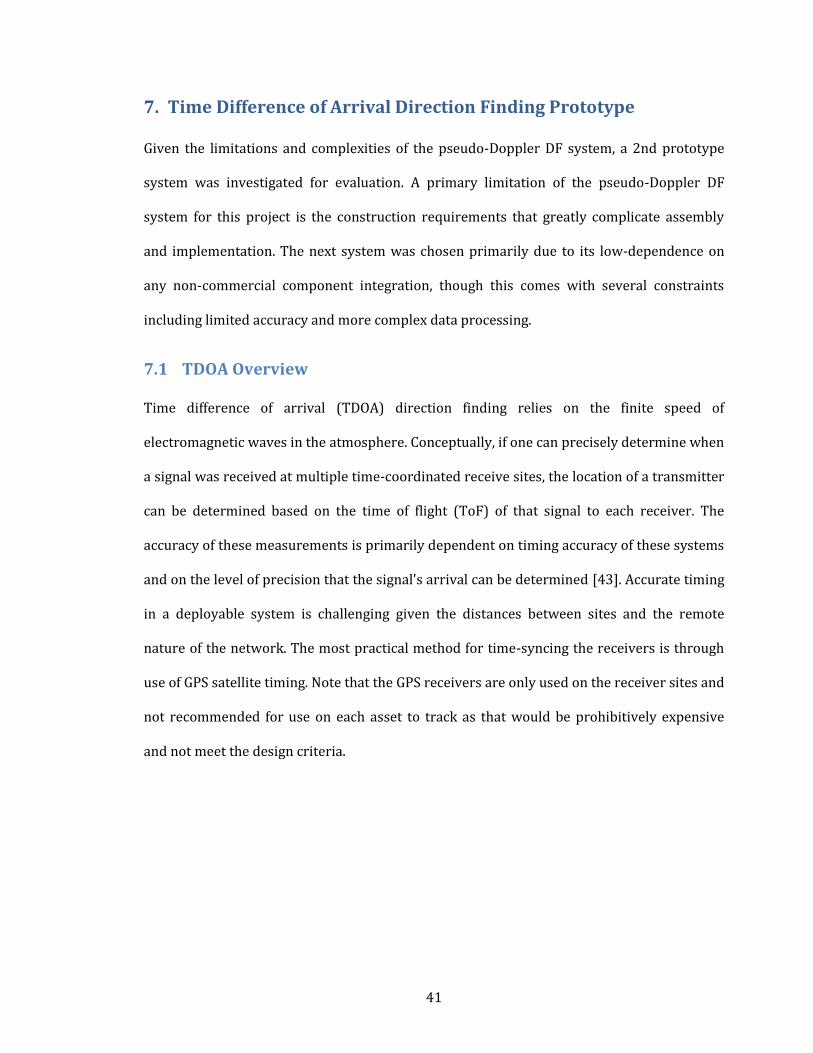
6.5 Pseudo-Doppler Results
The pseudo-Doppler RDF system proved to be successfully developed into a microcontroller-
driven DSP proof-of-concept that is able to receive and calculate signal directions. One major
problem with the prototype is that of multipath distortion that occurs when the source signal
reaches the Doppler array time-delayed. This causes additional zero-crossings in the DSP
stage and produces erroneous readings such as those in Figure 32, where the received signal
is >30° off from the actual bearing. Further development of the system could include
implementing the DSP software in the Arduino UNO, though a different microprocessor
might be needed due to the limited processor power and storage on the ATMega328P.
Figure 32: SoundDoppler screenshot of a 146.5 MHz local transmitter with multipath
distortion

40
6.6 Conclusion on the Pseudo-Doppler Receiver
The unpredictable multi-path errors, large antenna array, and complicated system topology
make the system unsuitable. The system error was observed up to 30° from the desired
bearing. The antenna array was approximately 20"x20"x20" for the VHF system and requires
a magnetic ground plane for proper operation. Even with a simplified antenna switcher and a
modernized control circuit, the system is complicated and can quickly become expensive
after final integration into a deployable package. The pseudo-Doppler RDF receiver is
conceptually a very capable system, but in practice is quite complex to develop and
implement. Given the design criteria of this project, the pseudo-Doppler system is quickly
found to lose footing as a viable solution. For these reasons, the pseudo-Doppler system does
not meet the primary problem specifications for low-cost and simplicity and is therefore no
longer a viable solution.
41
7. Time Difference of Arrival Direction Finding Prototype
Given the limitations and complexities of the pseudo-Doppler DF system, a 2nd prototype
system was investigated for evaluation. A primary limitation of the pseudo-Doppler DF
system for this project is the construction requirements that greatly complicate assembly
and implementation. The next system was chosen primarily due to its low-dependence on
any non-commercial component integration, though this comes with several constraints
including limited accuracy and more complex data processing.
7.1 TDOA Overview
Time difference of arrival (TDOA) direction finding relies on the finite speed of
electromagnetic waves in the atmosphere. Conceptually, if one can precisely determine when
a signal was received at multiple time-coordinated receive sites, the location of a transmitter
can be determined based on the time of flight (ToF) of that signal to each receiver. The
accuracy of these measurements is primarily dependent on timing accuracy of these systems
and on the level of precision that the signal's arrival can be determined [43]. Accurate timing
in a deployable system is challenging given the distances between sites and the remote
nature of the network. The most practical method for time-syncing the receivers is through
use of GPS satellite timing. Note that the GPS receivers are only used on the receiver sites and
not recommended for use on each asset to track as that would be prohibitively expensive
and not meet the design criteria.
42
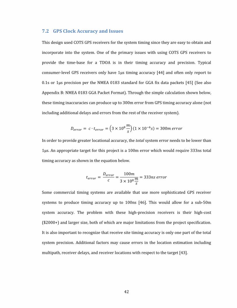
7.2 GPS Clock Accuracy and Issues
This design used COTS GPS receivers for the system timing since they are easy to obtain and
incorporate into the system. One of the primary issues with using COTS GPS receivers to
provide the time-base for a TDOA is in their timing accuracy and precision. Typical
consumer-level GPS receivers only have 1µs timing accuracy [44] and often only report to
0.1s or 1µs precision per the NMEA 0183 standard for GGA fix data packets [45] (See also
Appendix B: NMEA 0183 GGA Packet Format). Through the simple calculation shown below,
these timing inaccuracies can produce up to 300m error from GPS timing accuracy alone (not
including additional delays and errors from the rest of the receiver system).
In order to provide greater locational accuracy, the total system error needs to be lower than
1µs. An appropriate target for this project is a 100m error which would require 333ns total
timing accuracy as shown in the equation below.
Some commercial timing systems are available that use more sophisticated GPS receiver
systems to produce timing accuracy up to 100ns [46]. This would allow for a sub-50m
system accuracy. The problem with these high-precision receivers is their high-cost
($2000+) and larger size, both of which are major limitations from the project specification.
It is also important to recognize that receive site timing accuracy is only one part of the total
system precision. Additional factors may cause errors in the location estimation including
multipath, receiver delays, and receiver locations with respect to the target [43].
43
7.3 TDOA System Configuration
The COTS TDOA implementation is surprisingly simple in its hardware configuration. The
entire system only requires a radio transceiver, a GPS module, and some form of
microcontroller to interface between them. Since the proof-of-concept was to integrate with
the amateur radio APRS network, finding components to build this prototype focused on the
same companies that manufacture equipment for the amateur radio community. Argent Data
Systems (ADS) is located in Santa Maria, CA and manufactures one of the world's most
widely used APRS systems known as the Open Tracker series [47]. The Open Tracker is a
device that interfaces a radio with the APRS network and controls everything from packets
handling and audio levels to telemetry and GPS interfacing. ADS is focused on creating high-
quality, low-cost, and open-source hardware for the amateur radio community, but also
supplies commercial fleet management companies that utilize Garmin's Fleet Management
Interface to coordinate their vehicles on the road. Given these factors, the TDOA prototype
was designed from ADS components in order to simplify the system. It should be noted that
equivalent system components are available from other manufacturers (e.g. Byonics [48])
but with potentially reduced functionality. The Open Tracker series comes in a variety of
form factors for different applications, but for this project the newer T3-301 was chosen
because it contains both a Tracker3 module and a 5 watt VHF transceiver in one compact
package. The simplicity of this form factor specifically targets one of the project's design
criteria and the availability of all the components for the project from one manufacturer
exemplifies this.
44
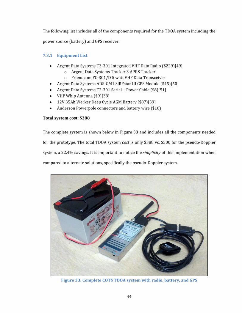
The following list includes all of the components required for the TDOA system including the
power source (battery) and GPS receiver.
7.3.1 Equipment List
Argent Data Systems T3-301 Integrated VHF Data Radio ($229)[49]
o Argent Data Systems Tracker 3 APRS Tracker
o Friendcom FC-301/D 5 watt VHF Data Transceiver
Argent Data Systems ADS-GM1 SiRFstar III GPS Module ($45)[50]
Argent Data Systems T2-301 Serial + Power Cable ($8)[51]
VHF Whip Antenna ($9)[38]
12V 35Ah Werker Deep Cycle AGM Battery ($87)[39]
Anderson Powerpole connectors and battery wire ($10)
Total system cost: $388
The complete system is shown below in Figure 33 and includes all the components needed
for the prototype. The total TDOA system cost is only $388 vs. $500 for the pseudo-Doppler
system, a 22.4% savings. It is important to notice the simplicity of this implementation when
compared to alternate solutions, specifically the pseudo-Doppler system.
Figure 33: Complete COTS TDOA system with radio, battery, and GPS
45
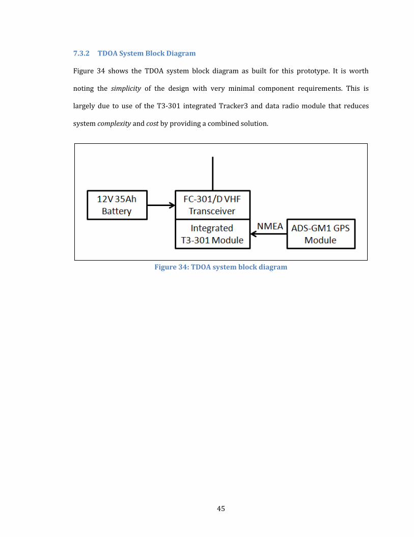
7.3.2 TDOA System Block Diagram
Figure 34 shows the TDOA system block diagram as built for this prototype. It is worth
noting the simplicity of the design with very minimal component requirements. This is
largely due to use of the T3-301 integrated Tracker3 and data radio module that reduces
system complexity and cost by providing a combined solution.
Figure 34: TDOA system block diagram
46
7.4 TDOA System Component Validation
In order to analyze the contribution and durability of each component of the system, the sub-
sections of the TDOA system are individually investigated.
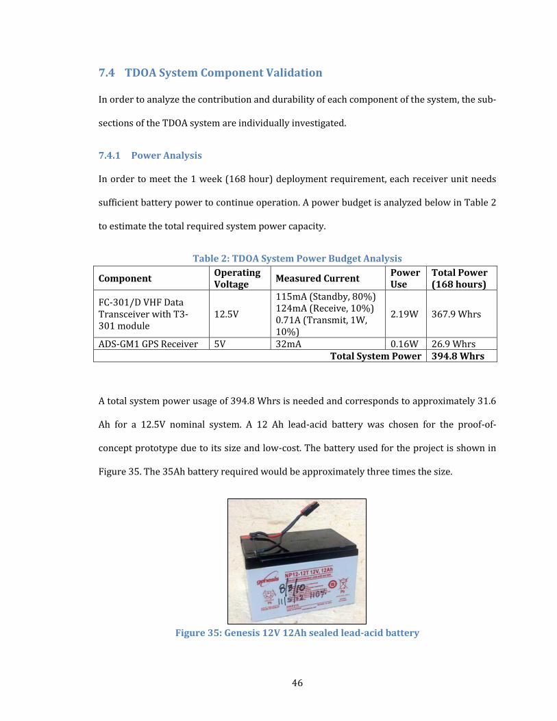
7.4.1 Power Analysis
In order to meet the 1 week (168 hour) deployment requirement, each receiver unit needs
sufficient battery power to continue operation. A power budget is analyzed below in Table 2
to estimate the total required system power capacity.
Table 2: TDOA System Power Budget Analysis
Component Operating Voltage
Measured Current Power Use
Total Power (168 hours)
FC-301/D VHF Data Transceiver with T3-301 module
12.5V
115mA (Standby, 80%) 124mA (Receive, 10%) 0.71A (Transmit, 1W, 10%)
2.19W 367.9 Whrs
ADS-GM1 GPS Receiver 5V 32mA 0.16W 26.9 Whrs Total System Power 394.8 Whrs
A total system power usage of 394.8 Whrs is needed and corresponds to approximately 31.6
Ah for a 12.5V nominal system. A 12 Ah lead-acid battery was chosen for the proof-of-
concept prototype due to its size and low-cost. The battery used for the project is shown in
Figure 35. The 35Ah battery required would be approximately three times the size.
Figure 35: Genesis 12V 12Ah sealed lead-acid battery
47
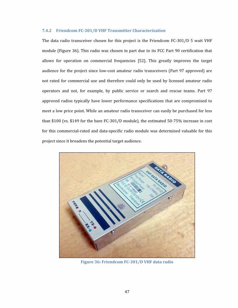
7.4.2 Friendcom FC-301/D VHF Transmitter Characterization
The data radio transceiver chosen for this project is the Friendcom FC-301/D 5 watt VHF
module (Figure 36). This radio was chosen in part due to its FCC Part 90 certification that
allows for operation on commercial frequencies [52]. This greatly improves the target
audience for the project since low-cost amateur radio transceivers (Part 97 approved) are
not rated for commercial use and therefore could only be used by licensed amateur radio
operators and not, for example, by public service or search and rescue teams. Part 97
approved radios typically have lower performance specifications that are compromised to
meet a low price point. While an amateur radio transceiver can easily be purchased for less
than $100 (vs. $149 for the bare FC-301/D module), the estimated 50-75% increase in cost
for this commercial-rated and data-specific radio module was determined valuable for this
project since it broadens the potential target audience.
Figure 36: Friendcom FC-301/D VHF data radio
48
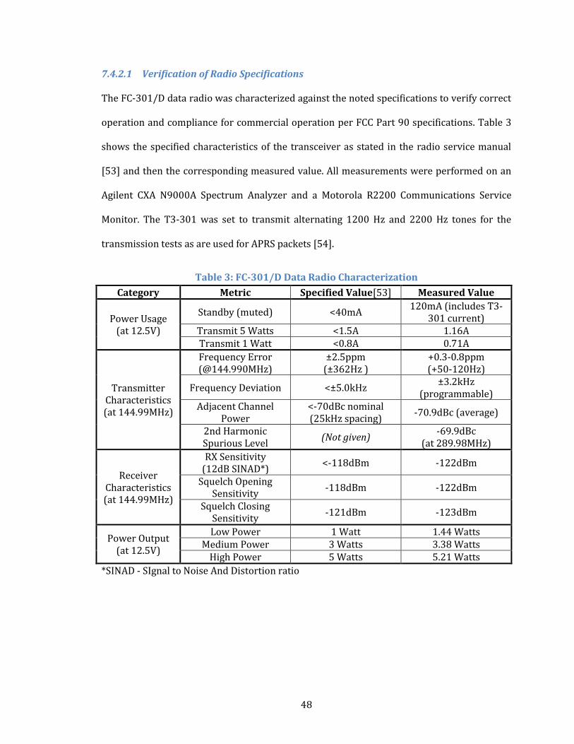
7.4.2.1 Verification of Radio Specifications
The FC-301/D data radio was characterized against the noted specifications to verify correct
operation and compliance for commercial operation per FCC Part 90 specifications. Table 3
shows the specified characteristics of the transceiver as stated in the radio service manual
[53] and then the corresponding measured value. All measurements were performed on an
Agilent CXA N9000A Spectrum Analyzer and a Motorola R2200 Communications Service
Monitor. The T3-301 was set to transmit alternating 1200 Hz and 2200 Hz tones for the
transmission tests as are used for APRS packets [54].
Table 3: FC-301/D Data Radio Characterization
Category Metric Specified Value[53] Measured Value
Power Usage (at 12.5V)
Standby (muted) <40mA 120mA (includes T3-
301 current) Transmit 5 Watts <1.5A 1.16A Transmit 1 Watt <0.8A 0.71A
Transmitter Characteristics (at 144.99MHz)
Frequency Error (@144.990MHz)
±2.5ppm (±362Hz )
+0.3-0.8ppm (+50-120Hz)
Frequency Deviation <±5.0kHz ±3.2kHz
(programmable) Adjacent Channel
Power <-70dBc nominal (25kHz spacing)
-70.9dBc (average)
2nd Harmonic Spurious Level
(Not given) -69.9dBc
(at 289.98MHz)
Receiver Characteristics (at 144.99MHz)
RX Sensitivity (12dB SINAD*)
<-118dBm -122dBm
Squelch Opening Sensitivity
-118dBm -122dBm
Squelch Closing Sensitivity
-121dBm -123dBm
Power Output (at 12.5V)
Low Power 1 Watt 1.44 Watts Medium Power 3 Watts 3.38 Watts
High Power 5 Watts 5.21 Watts
*SINAD - SIgnal to Noise And Distortion ratio
49
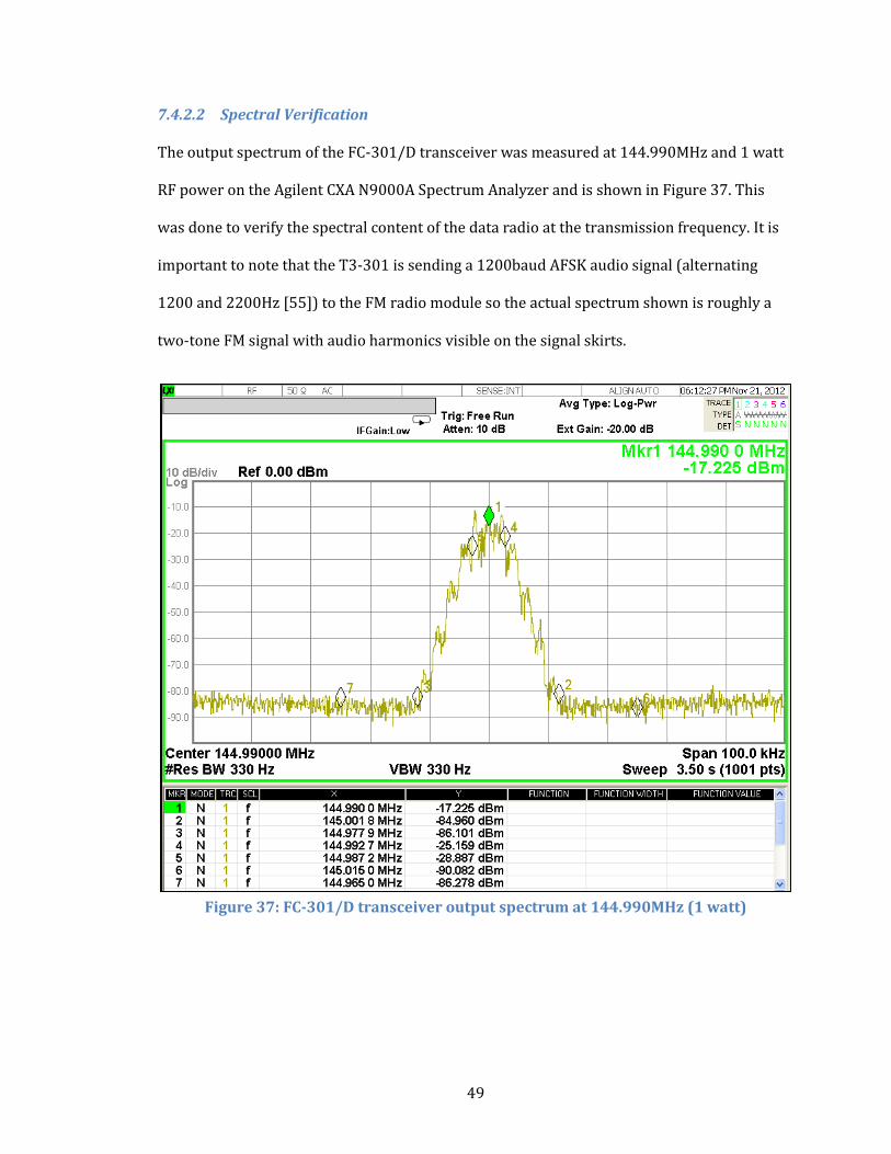
7.4.2.2 Spectral Verification
The output spectrum of the FC-301/D transceiver was measured at 144.990MHz and 1 watt
RF power on the Agilent CXA N9000A Spectrum Analyzer and is shown in Figure 37. This
was done to verify the spectral content of the data radio at the transmission frequency. It is
important to note that the T3-301 is sending a 1200baud AFSK audio signal (alternating
1200 and 2200Hz [55]) to the FM radio module so the actual spectrum shown is roughly a
two-tone FM signal with audio harmonics visible on the signal skirts.
Figure 37: FC-301/D transceiver output spectrum at 144.990MHz (1 watt)
50
7.5 T3-301 APRS Module Configuration
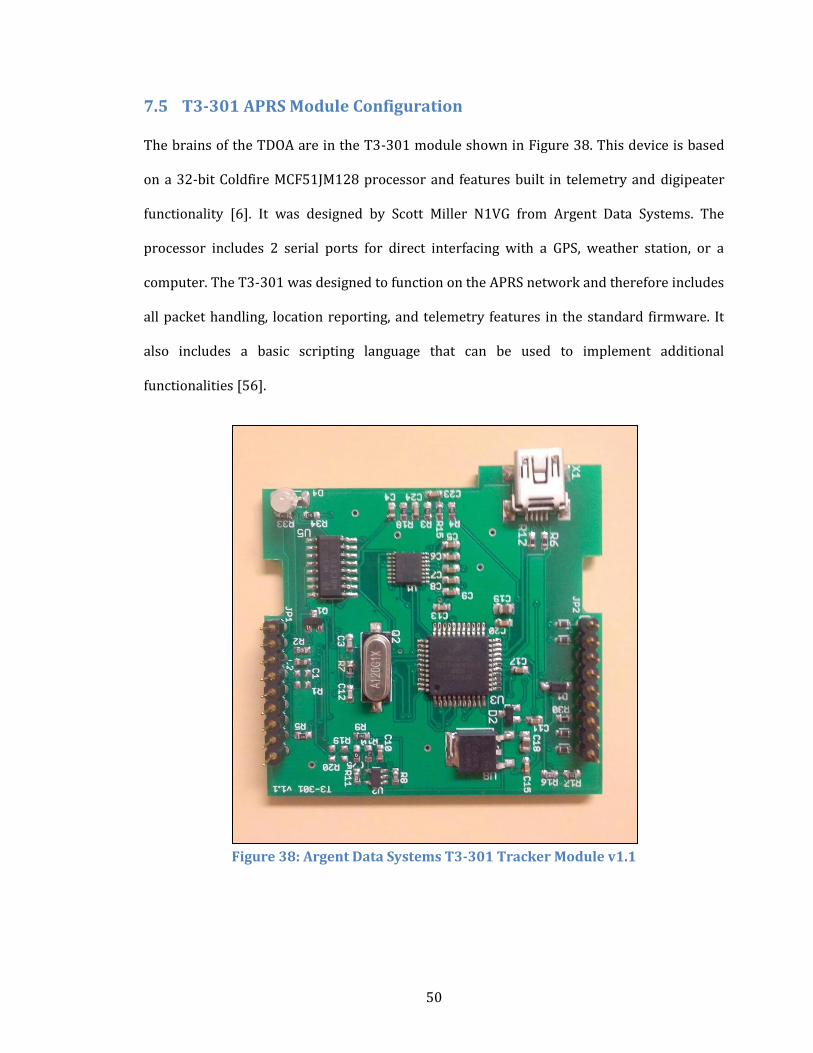
The brains of the TDOA are in the T3-301 module shown in Figure 38. This device is based
on a 32-bit Coldfire MCF51JM128 processor and features built in telemetry and digipeater
functionality [6]. It was designed by Scott Miller N1VG from Argent Data Systems. The
processor includes 2 serial ports for direct interfacing with a GPS, weather station, or a
computer. The T3-301 was designed to function on the APRS network and therefore includes
all packet handling, location reporting, and telemetry features in the standard firmware. It
also includes a basic scripting language that can be used to implement additional
functionalities [56].
Figure 38: Argent Data Systems T3-301 Tracker Module v1.1
51
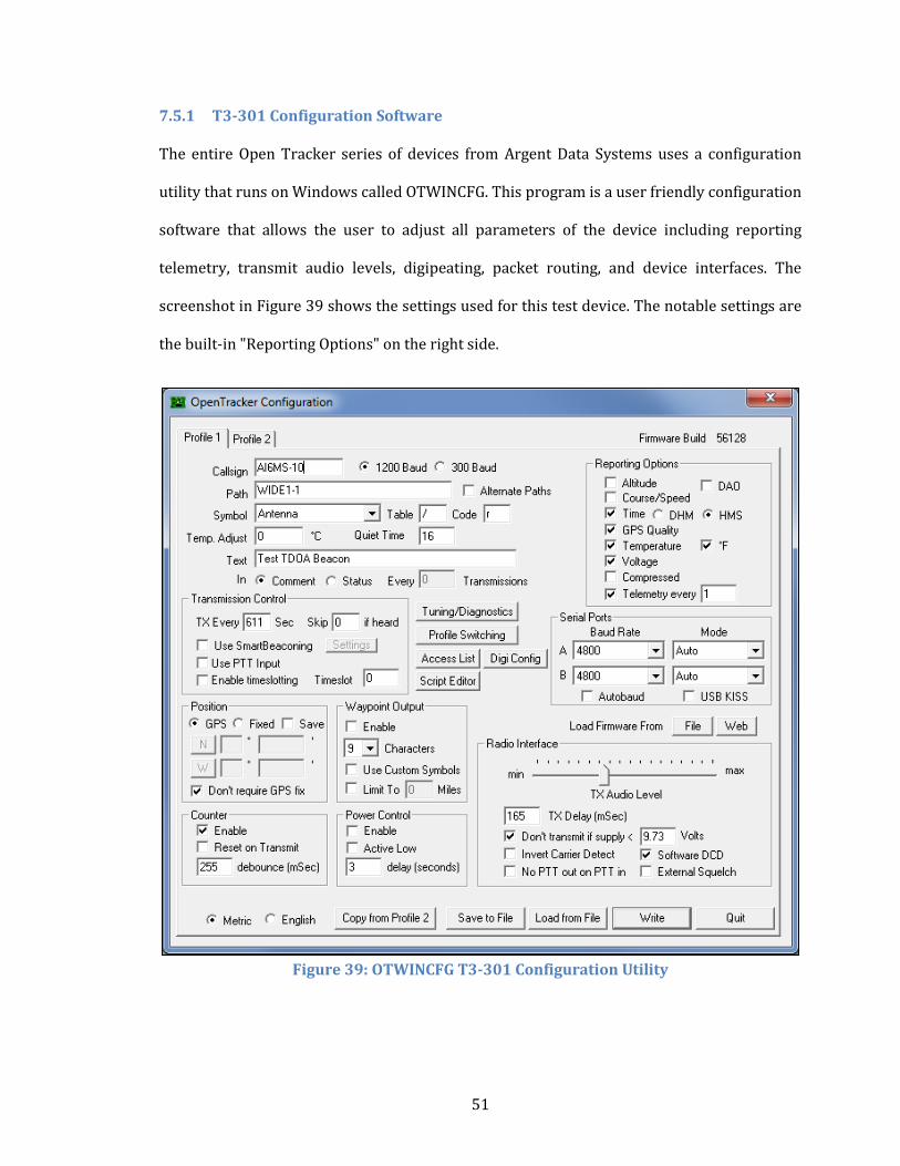
7.5.1 T3-301 Configuration Software
The entire Open Tracker series of devices from Argent Data Systems uses a configuration
utility that runs on Windows called OTWINCFG. This program is a user friendly configuration
software that allows the user to adjust all parameters of the device including reporting
telemetry, transmit audio levels, digipeating, packet routing, and device interfaces. The
screenshot in Figure 39 shows the settings used for this test device. The notable settings are
the built-in "Reporting Options" on the right side.
Figure 39: OTWINCFG T3-301 Configuration Utility
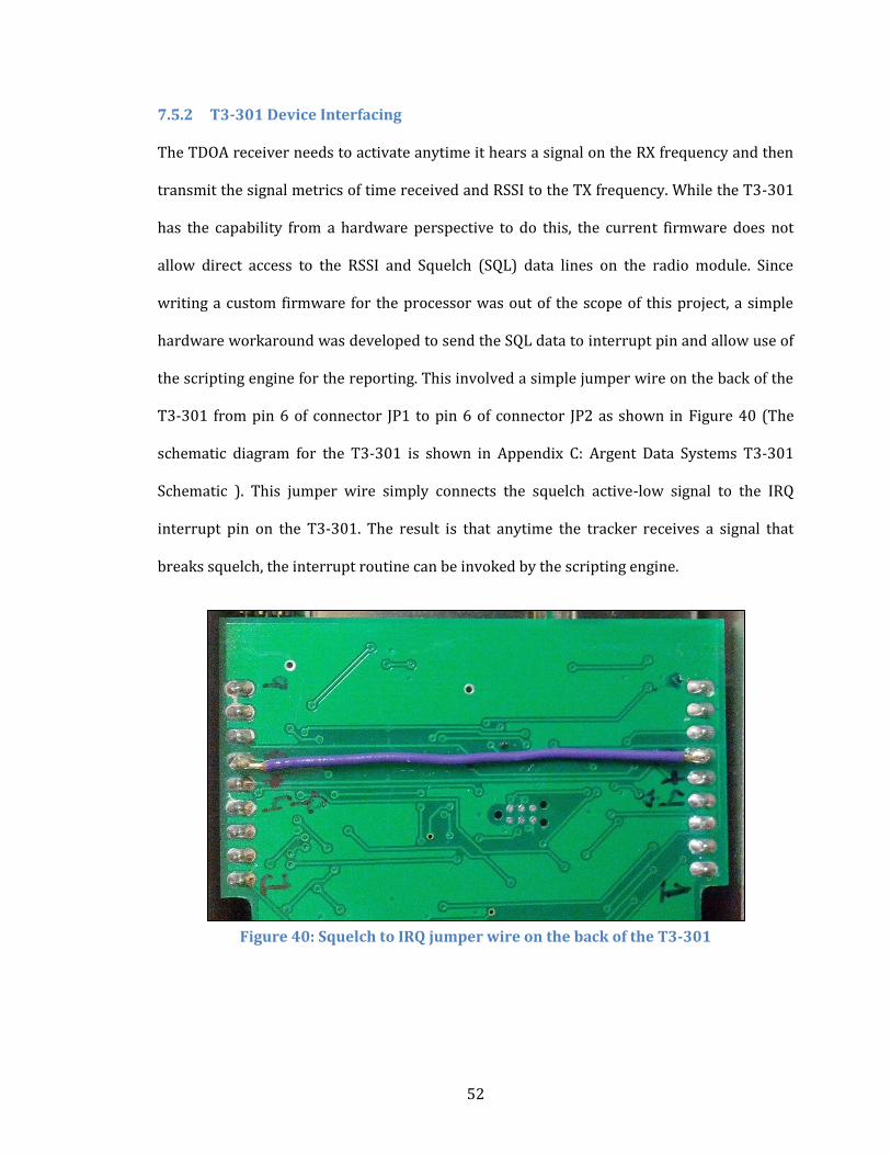
52
7.5.2 T3-301 Device Interfacing
The TDOA receiver needs to activate anytime it hears a signal on the RX frequency and then
transmit the signal metrics of time received and RSSI to the TX frequency. While the T3-301
has the capability from a hardware perspective to do this, the current firmware does not
allow direct access to the RSSI and Squelch (SQL) data lines on the radio module. Since
writing a custom firmware for the processor was out of the scope of this project, a simple
hardware workaround was developed to send the SQL data to interrupt pin and allow use of
the scripting engine for the reporting. This involved a simple jumper wire on the back of the
T3-301 from pin 6 of connector JP1 to pin 6 of connector JP2 as shown in Figure 40 (The
schematic diagram for the T3-301 is shown in Appendix C: Argent Data Systems T3-301
Schematic ). This jumper wire simply connects the squelch active-low signal to the IRQ
interrupt pin on the T3-301. The result is that anytime the tracker receives a signal that
breaks squelch, the interrupt routine can be invoked by the scripting engine.
Figure 40: Squelch to IRQ jumper wire on the back of the T3-301
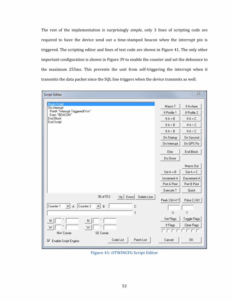
53
The rest of the implementation is surprisingly simple, only 3 lines of scripting code are
required to have the device send out a time-stamped beacon when the interrupt pin is
triggered. The scripting editor and lines of test code are shown in Figure 41. The only other
important configuration is shown in Figure 39 to enable the counter and set the debounce to
the maximum 255ms. This prevents the unit from self-triggering the interrupt when it
transmits the data packet since the SQL line triggers when the device transmits as well.
Figure 41: OTWINCFG Script Editor
54
7.6 TDOA System Results
Basic functionality of the TDOA system was proven in the following test. The current
implementation is complete from a hardware perspective but requires additional software
and firmware development to have full system-level functionality.
7.6.1 APRS Packet Results
The TDOA system responds immediately to any on-frequency traffic as designed and
transmits the following packet information each time:
AI6MS-10>APOT30,WIDE1-1:>Test TDOA Beacon
AI6MS-10>APOT30,WIDE1-1:/231915h3518.51N/12039.56Wr 12.6V
72F CNT00003 HDOP02.2 SATS06
AI6MS-10>APOT30,WIDE1-1:T#000,126,057,062,052,048,00000010
The first packet shows a simple status packet from the system to properly identify the
station and stay in compliance with FCC Part 97 rules during testing. The second packet is
the standard BEACON packet from the T3-301 and contains time, GPS latitude and longitude,
system voltage, temperature, packet count, HDOP, and the number of satellites used. The
primary issue with this packet is the imprecision of the reported time (further discussed in
section 7.6.3 COTS Timing Challenges). The third packet shows a standard telemetry packet
as reported by the T3-301. The basic information presented is the packet ID number, system
temperature, voltage, ADC value, IRQ counter, and HDOP value. These are presented on a
linear scale from 0 to 255. Further documentation on this format is found in the Argent Data
Systems website and is the format in which RSSI could easily be reported via software
changes to the T3-301 [57].
55
7.6.2 COTS Hardware Implementation
The primary challenge in creating a low-cost TDOA system for this project is in maintaining
the COTS implementation requirement for simple construction and deployment capabilities.
In order for the RDFN to successfully meet the project requirements, it needs to be easily
assembled from commercially available components. One of the drawbacks of the current
implementation is the necessity for a hardware jumper wire to activate the signal triggering.
The hardware jumper also means that the device cannot be easily reconfigured for alternate
operation without physically removing this wire. Fortunately, the device is capable of
implementing the jumper in software and a request has been made to Argent Data Systems
to develop this code for open source implementation in the future.
7.6.3 COTS Timing Challenges
The second issue with the current implementation is in obtaining the necessary timing
accuracy for precise locating capabilities. As the prototype stands now, the reported time is
only reported to 1 second precision as is default in the code. This does not provide enough
accuracy for TDOA calculations unless the time of arrival can be calculated with respect to
the second using a counter or something similar. Again with some small changes to the
firmware, at least 1 ms precision with 1µs accuracy can be obtained from the GPS unit and
reported along with rest of the signal metrics. Another useful piece of data that is currently
transmitted is the horizontal dilution of precision (HDOP). HDOP is a measure of the GPS
location accuracy and can be used in calculating the probable transmitter location [58].
Depending on the exact GPS module used, there is potential for additional GPS signal
reporting of time and vertical dilution of precision (TDOP and VDOP), clock drift, and clock
frequency, all of which could be used by the central receive station to achieve even greater
signal timing accuracy [59]. These changes are all software based implementations that are
further addressed in Section 8.2 Future Project Developments.
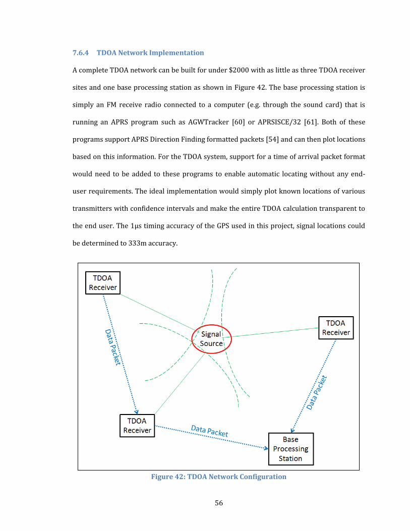
56
7.6.4 TDOA Network Implementation
A complete TDOA network can be built for under $2000 with as little as three TDOA receiver
sites and one base processing station as shown in Figure 42. The base processing station is
simply an FM receive radio connected to a computer (e.g. through the sound card) that is
running an APRS program such as AGWTracker [60] or APRSISCE/32 [61]. Both of these
programs support APRS Direction Finding formatted packets [54] and can then plot locations
based on this information. For the TDOA system, support for a time of arrival packet format
would need to be added to these programs to enable automatic locating without any end-
user requirements. The ideal implementation would simply plot known locations of various
transmitters with confidence intervals and make the entire TDOA calculation transparent to
the end user. The 1µs timing accuracy of the GPS used in this project, signal locations could
be determined to 333m accuracy.
Figure 42: TDOA Network Configuration

57
8. Conclusion and Future Work
This project is set out to provide the basic system-level testing and analysis to prove the
feasibility of a low-cost, deployable, VHF radio direction finding network. In order to
maintain the primary project goal of commercial off-the-shelf (COTS) construction, several
design compromises were necessary to maintain cost and complexity requirements. A more-
precise (and thus higher-cost) system can easily be developed using more complex systems
and custom hardware, but would ultimately fall outside the scope of this project. The
pseudo-Doppler RDF receiver proved to require far more complex construction than was
desired for this project and also proved to have directional accuracy errors of 30° in certain
situations. The TDOA RDF receiver proved to be exceptionally simple to assemble and was
functional at a very basic level with minimal code requirement for the receiver unit.
Additional software developments are necessary to make the TDOA receiver a practical
solution for development into an RDFN. Additionally, the TDOA system uses a consumer-
level GPS that has clock accuracy resulting in greater than 300m locational error.
The feasibility of a low-cost, deployable RDF receiver was proven with the TDOA design
which is implemented entirely from COTS components and has a total system cost of $388.
This proof-of-concept will likely see further development from future project work and find
its way into regular use in public service and disaster response organizations worldwide.
58
8.1 Contributions
This thesis project has made numerous contributions to the development of a low-cost COTS
RDF receiver.
Proven feasibility of a RDFN that is backwards compatible with existing handheld
and mobile VHF radios currently used by public service groups with no other major
infrastructure required to provide locating services.
A low-cost system developed entirely from commercially available components is
now possible at less than $500 per receive site. This results in a minimum total
system cost of under $1500 with unlimited expansion capabilities and complete fault
tolerance through redundant site usage.
The RDFN is simple to implement and is based on an existing support network of
amateur radio operators who are intimately familiar with the APRS network and
already closely involved with public service through ARES and RACES.
The author has worked closely with both Argent Data Systems to provide
improvements and technical documentation support for the Open Tracker products.
This thesis topic was presented by the author at the National Convention for
Amateur Radio held at the Pacificon Convention in Santa Clara, CA on October 12-14,
2012 [62]. This presentation brought much feedback and positive response from the
amateur radio community. Several amateur radio operators have expressed interest
in the final product and are in communication with the author for future
developments. Given the vastly positive response to this project, the author plans to
publish his work in QST, the national magazine for amateur radio and also to work
closely with several students who have already expressed interest at continuing the
project research.
59
8.2 Future Project Developments
Throughout the development of this project, numerous improvements and additional
research areas were identified. These maybe of interest to future senior project or master's
students and other individuals interested in contributing to the work. The following list
briefly summarizes some of these areas for future project development:
Improved Receiver Clock Accuracy and Precision
o Additional research into improving the receiver time synchronization would
greatly improve the TDOA system viability. D-GPS could also be used to
improve the timing accuracy. A detailed look at the system's clock
distribution could find additional areas for improvement [43]
Radio Transmitter Fingerprinting (via store-and-forward)
o A very promising area of study is in transmitter fingerprinting which allows
for individual transmitters to be identified through their initial VCO locking
characteristics as they are presented in the FM signal. This could allow for
uniquely identifiable locating capabilities without the need for any additional
equipment or infrastructure.
Baseband RF Phase or Audio TDOA
o Instead of using the squelch of the transceiver (which has timing
inaccuracies) to detect an incoming signal, one could measure the precise RF
baseband signal or specific audio crossing point to improve accuracy.
Environmental Fingerprinting (location calibration)
o This subject involves periodic system calibration using a series of known
transmitter locations to characterize the coverage area and improve locating
capabilities of the system.
60
Active user calibration (real-time calibration using known sources)
o As an extension from Environmental Fingerprinting, certain transmitters or
fixed beacons could remain in the coverage area to actively recalibrate the
system to maintain system accuracy over time and changing conditions.
Frequency agile operation, remote reprogramming, start-up, and shutdown capable
o Technically this is already possible with the existing system by using the
remote access feature of the T3-301, but further research can be done to take
advantage of these features to provide active monitoring on multiple
frequencies and systems.
Indefinite stand-alone remote operation with solar power system
o A relatively simple improvement to this system is to add a photovoltaic panel
to the system to improve the power system and allow indefinite operation.
Networked weather reporting sites
o Another simple improvement to the RDFN is the addition of weather stations
to provide real-time telemetry to the user. This is especially important for
wildland firefighters who rely heavily on wind and temperature forecasts to
allocate resources. The T3-301 has built in weather station capabilities so
this improvement is quite trivial and would simply require added cost and
receiver size to include the sensors.
Commercialization
o The final step for this project would be to bring it the product to market so
that public service groups can easily take advantage of the system. Once the
actual receiver accuracy is improved, the simple addition of a rugged
enclosure would provide a promising product to use for an RDFN.
61
9. Bibliography
[1] S. E. Lipsky, Mircowave Passive Direction Finding, New York: John Wiley & Sons, Inc., 1987.
[2] J. F. Bull, "Wireless Geolocation," IEEE Vehiclular Technology Magazine, pp. 45-53, 2009.
[3] LoJack Corporation, "LoJack System for Cars, Trucks and Classics," 2012. [Online]. Available: http://lojack.com/Cars-Trucks-And-Classics/How-LoJack-Works. [Accessed November 2012].
[4] National Conference of Volunteer Examiner Coordinators, "Element 2 Technician Class Question Pool," 1 July 2010. [Online]. Available: http://www.ncvec.org/downloads/Revised%20Element%202.Pdf. [Accessed November 2012].
[5] R. Parry, "Position Reporting with APRS," [Online]. Available: http://www.arrl.org/position-reporting-with-aprs. [Accessed November 2012].
[6] Argent Data Systems, "Tracker3 Series APRS Tracker," 2012. [Online]. Available: https://www.argentdata.com/products/tracker3.html. [Accessed November 2012].
[7] National Oceanic and Atmospheric Administration, "Emergency Beacons," [Online]. Available: http://www.sarsat.noaa.gov/emerbcns.html. [Accessed November 2012].
[8] California Department of Forestry and Fire Protection, "Overview of the Accident," 11 May 2005. [Online]. Available: http://www.fire.ca.gov/fire_protection/downloads/404_investigation_3of5_main-part2of2.pdf. [Accessed November 2012].
[9] P. Gething, Radio direction-finding and the resolution of multicomponent wave-fields, London: Peter Peregrinus Ltd., 1978.
[10] K. B. Williams, Secret Weapon - U.S. High-Frequency Direction Finding in the Battle of the Atlantic, Annapolis: Naval Institue Press, 1996.
[11] RDF Products, "Prdocut Data Sheet Model DFA-1248B1," 2007. [Online]. Available: http://www.rdfproducts.com/dfa1248b1_pds_01.pdf. [Accessed November 2012].
[12] K. Halliwell, "NSGA Homestead, Florida," December 1970. [Online]. Available: http://www.navycthistory.com/homestead_KJH_1.html. [Accessed November 2012].
[13] United States Coast Guard, "Planning Process for the National Distress and Response System Modernization Project," 4 February 2002. [Online]. Available:
62
http://www.oig.dot.gov/sites/dot/files/pdfdocs/mh2002076.pdf. [Accessed November 2012].
[14] United States Coast Guard, "Acquisition Directorate Rescue 21," July 2012. [Online]. Available: http://www.uscg.mil/acquisition/rescue21/pdf/rescue21.pdf. [Accessed November 2012].
[15] United States Coast Guard, "Rescue 21: Image Gallery," 10 February 2004. [Online]. Available: http://www.flickr.com/photos/coast_guard/7204749914/in/set-72157629497106120/. [Accessed November 2012].
[16] Civil Air Patrol National Headquarters, "Emergency Services," 2102. [Online]. Available: http://www.gocivilairpatrol.com/about/civil_air_patrols_three_primary_missions/emergency-services/. [Accessed November 2012].
[17] L-Tronics Company, "LL Series Little L-Per Portable Direction Finder," January 2011. [Online]. Available: http://www.ltronics.com/ll-16df.htm. [Accessed November 2012].
[18] Spot LLC., "SPOT Satellite GPS Messenger," 2012. [Online]. Available: http://www.findmespot.com/downloads/SPOT2-SellSheet.pdf. [Accessed November 2012].
[19] Backcountry Access, "Tracker DTS," 2012. [Online]. Available: http://www.backcountryaccess.com/product/tracker-dts/. [Accessed November 2012].
[20] U.S. Geological Survey, "A Critique of Wildlife Radio-tracking and its Use in National Parks," Northern Prairie Wildlife Research Center, 3 August 2006. [Online]. Available: http://www.npwrc.usgs.gov/resource/wildlife/radiotrk/convent.htm. [Accessed November 2012].
[21] C. Ziegler, "Tiny Radio Tags Offer Rare Glimpse into Bees' Universe," National Geographic News, 14 November 2008. [Online]. Available: http://news.nationalgeographic.com/news/bigphotos/21191490.html. [Accessed November 2012].
[22] Conservacion Patagonica, "Huemul Deer Recovery," [Online]. Available: http://www.patagonialandtrust.org/buildingthepark_biodiversity_huemul.htm. [Accessed November 2012].
[23] Motorcycle.com, "LoJack," 2012. [Online]. Available: http://www.motorcycle.com/gallery/gallery.php/d/175355-2/LoJack_GM5V1404.jpg. [Accessed November 2012].
[24] Federal Communications Commission, "FCC Takes Action to Improve Wireless 9-1-1 Services," 23 September 2010. [Online]. Available: http://fjallfoss.fcc.gov/edocs_public/attachmatch/DOC-301653A1.pdf. [Accessed
63
November 2012].
[25] Federal Communications Commission, "Wireless 911 Services FCC Consumer Facts," 2 February 2012. [Online]. Available: http://transition.fcc.gov/cgb/consumerfacts/wireless911srvc.pdf. [Accessed November 2012].
[26] TruePosition, "TruePosition Location Platform," 2009. [Online]. Available: http://www.trueposition.com/trueposition-location-platform-overview-fact-sheet/DownloadSecured. [Accessed November 2012].
[27] G. Smith, "Cell Phone Problems Persist As Wireless Carriers Repair Damage From Hurricane Sandy," Huffington Post, 1 November 2012. [Online]. Available: http://www.huffingtonpost.com/2012/11/01/cellphone-problems-persist-after-hurricane-sandy_n_2060279.html. [Accessed November 2012].
[28] U.S. Government Accountability Office, "Improvements Needed in Management and Oversight of Rescue System Acquisition," May 2006. [Online]. Available: http://www.gao.gov/assets/260/250321.pdf. [Accessed November 2012].
[29] M. Kossor, "A Doppler Radio-Direction Finder Part 2," QST, pp. 37-40, June 1999.
[30] Doppler DF Instruments, "X-Dopp: Experimental Dopplers," [Online]. Available: http://www.silcom.com/~pelican2/PicoDopp/XDOPP.htm. [Accessed November 2012].
[31] M. Kossor, "A Doppler Radio-Direction Finder Part 1," QST, pp. 35-40, May 1999.
[32] J. D. Moell and T. N. Curlee, Transmitter Hunting - Radio Direction Finding Simplified, Blue Ridge Summit: Tap Books Inc., 1987.
[33] J. J. Carr, Practical Antenna Handbook 4th Ed, New York: McGraw-Hill, 2001.
[34] Ham Radio Outlet, "Tram 1100 1/4 Wave 2m Mag Mount," 2012. [Online]. Available: http://www.hamradio.com/detail.cfm?pid=H0-009818. [Accessed November 2012].
[35] Sparkfun Electronics, "Arduino Uno - R3," [Online]. Available: https://www.sparkfun.com/products/11021. [Accessed November 2012].
[36] Argent Data Systems, "Tracker3 Model OT3m," 24 February 2012. [Online]. Available: https://www.argentdata.com/catalog/product_info.php?cPath=22&products_id=155. [Accessed November 2012].
[37] Argent Data Systems, "FC-301/D Data Radio - VHF," 6 November 2008. [Online]. Available: https://www.argentdata.com/catalog/product_info.php?cPath=25&products_id=110. [Accessed November 2012].
64
[38] Argent Data Systems, "16-Inch VHF BNC Rubber Duck Antenna," 4 September 2009. [Online]. Available: https://www.argentdata.com/catalog/product_info.php?cPath=25&products_id=131. [Accessed November 2012].
[39] Batteries Plus LLC, "WKDC12-35J 12V 35Ah Werker Deep Cycle AGM Battery 12V Werker SLA Sealed Lead Acid Battery," 2011. [Online]. Available: http://www.batteriesplus.com/product/45886-WKDC12--35J-12V-35Ah-Werker-Deep-Cycle-AGM-Battery/100085-1/102629-SLA-Sealed-Lead-Acid-Batteries/102645-Werker/12V.aspx. [Accessed November 2012].
[40] W. Hofman, "The PA8W Doppler RDF," 2011. [Online]. Available: http://members.chello.nl/~w.hofman/pa8w/dopplerRDF.htm. [Accessed November 2012].
[41] H. Jenniskens, "Doppler directionfinder (DDF96)," [Online]. Available: http://www.pe0ssb.jentronics.nl/ddf96.html. [Accessed November 2012].
[42] J. Kenny, "rev0wiki," 7 June 2012. [Online]. Available: http://rev0proto.com/wiki/index.php/Main_Page. [Accessed November 2012].
[43] J.-y. Yoon, J.-W. Kim, W.-Y. Lee and D.-S. Eom, "A TDoA-Based Localization Using Precise Time-Synchronization," Korea University, Seoul, 2012.
[44] Polstar Technologies Inc., "PGM-648 / PGM-248 High Sensitivity GPS Mouse Receiver," Zhubei.
[45] Garmin International, Inc., "GPS 18 Technical Specifications," Olathe, 2005.
[46] TimeTools, "T2000 GPS Clock Time Server," 2012. [Online]. Available: http://www.timetools.co.uk/time-servers/ref/gps-clock.htm. [Accessed November 2012].
[47] Argent Data Systems, "Welcome to Argent Data Systems," 2012. [Online]. Available: http://www.argentdata.com/. [Accessed November 2012].
[48] Byonics, LLC, "Byonics - Electronic Projects for Amateur Radio," 2012. [Online]. Available: http://byonics.com/. [Accessed November 2012].
[49] Argent Data Systems, "T3-301 5-Watt VHF Transceiver with Integrated Tracker3," 15 October 2012. [Online]. Available: https://www.argentdata.com/catalog/product_info.php?products_id=164. [Accessed November 2012].
[50] Argent Data Systems, "ADS-GM1 GPS Receiver," 28 January 2008. [Online]. Available: https://www.argentdata.com/catalog/product_info.php?cPath=23&products_id=85. [Accessed November 2012].

65
[51] Argent Data Systems, "T2-301 Serial + Power Cable," 5 June 2009. [Online]. Available: https://www.argentdata.com/catalog/product_info.php?cPath=21&products_id=125. [Accessed November 2012].
[52] Shenzhen Friendcom Technology Development Co., Ltd, "FC-301/D User Manual," Shenzhen, 2009.
[53] Shenzhen Friendcom Technology Development Co., Ltd, "FC-301/D Service Manual," Shenzhen.
[54] C. Mills, "APRS Protocol," 23 May 2009. [Online]. Available: http://info.aprs.net/index.php?title=Protocol. [Accessed November 2012].
[55] J. Kenny, "Rev0Trac," 22 November 2011. [Online]. Available: http://rev0proto.com/wiki/index.php/Rev0Trac. [Accessed November 2012].
[56] Argent Data Systems, "Tracker2 model OT2m User's Manual," Santa Maria, 2009.
[57] Argent Data Systems, "Telemetry," 12 May 2012. [Online]. Available: http://wiki.argentdata.com/index.php?title=Telemetry. [Accessed October 2012].
[58] C. Carter, "GPS Glossary," 2005. [Online]. Available: http://www.inventeksys.com/wp-content/uploads/2011/11/GPS_Facts_GPS_Glossary.pdf. [Accessed November 2012].
[59] SiRF Technology, Inc., "NMEA Reference Manual," May 2010. [Online]. Available: http://www.lte.com.tr/uploads/pdfd/50.pdf. [Accessed November 2012].
[60] G. Rossopoylos, "AGWTracker," 22 September 2011. [Online]. Available: http://www.agwtracker.com/. [Accessed November 2012].
[61] L. Deffenbaugh, "APRSISCE/32 The future of Amateur Radio APRS," 2 November 2012. [Online]. Available: http://aprsisce.wikidot.com/. [Accessed November 2012].
[62] American Radio Relay League Pacific Division, "Pacificon," Mt Diablo Amateur Radio Club, 2012. [Online]. Available: http://pacificon.org/. [Accessed November 2012].
[63] G. Baddeley, "GPS - NMEA sentence information," 24 May 2011. [Online]. Available: http://home.mira.net/~gnb/gps/nmea.html. [Accessed November 2012].
[64] Argent Data Systems, "T3-301 Schematic," November 2012. [Online]. Available: http://wiki.argentdata.com/index.php?title=File:T3-301_Schematic.png. [Accessed November 2012].
[65] G. West, "They’re ‘Taking the Search Out of Search And Rescue’," Popular Communications, pp. 10-11, July 2011.
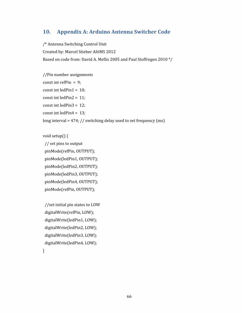
66
10. Appendix A: Arduino Antenna Switcher Code
/* Antenna Switching Control Unit
Created by: Marcel Stieber AI6MS 2012
Based on code from: David A. Mellis 2005 and Paul Stoffregen 2010 */
//Pin number assignments
const int refPin = 9;
const int ledPin1 = 10;
const int ledPin2 = 11;
const int ledPin3 = 12;
const int ledPin4 = 13;
long interval = 474; // switching delay used to set frequency (ms)
void setup() {
// set pins to output
pinMode(refPin, OUTPUT);
pinMode(ledPin1, OUTPUT);
pinMode(ledPin2, OUTPUT);
pinMode(ledPin3, OUTPUT);
pinMode(ledPin4, OUTPUT);
pinMode(refPin, OUTPUT);
//set initial pin states to LOW
digitalWrite(refPin, LOW);
digitalWrite(ledPin1, LOW);
digitalWrite(ledPin2, LOW);
digitalWrite(ledPin3, LOW);
digitalWrite(ledPin4, LOW);
}
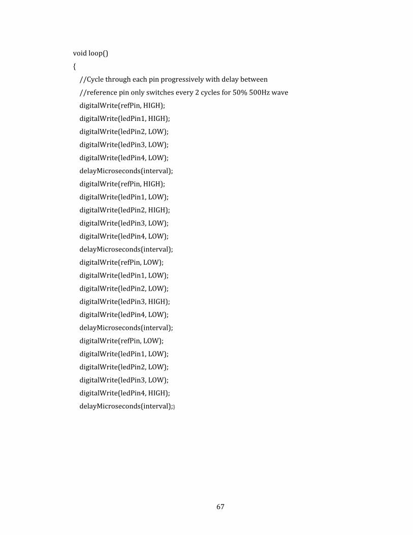
67
void loop()
{
//Cycle through each pin progressively with delay between
//reference pin only switches every 2 cycles for 50% 500Hz wave
digitalWrite(refPin, HIGH);
digitalWrite(ledPin1, HIGH);
digitalWrite(ledPin2, LOW);
digitalWrite(ledPin3, LOW);
digitalWrite(ledPin4, LOW);
delayMicroseconds(interval);
digitalWrite(refPin, HIGH);
digitalWrite(ledPin1, LOW);
digitalWrite(ledPin2, HIGH);
digitalWrite(ledPin3, LOW);
digitalWrite(ledPin4, LOW);
delayMicroseconds(interval);
digitalWrite(refPin, LOW);
digitalWrite(ledPin1, LOW);
digitalWrite(ledPin2, LOW);
digitalWrite(ledPin3, HIGH);
digitalWrite(ledPin4, LOW);
delayMicroseconds(interval);
digitalWrite(refPin, LOW);
digitalWrite(ledPin1, LOW);
digitalWrite(ledPin2, LOW);
digitalWrite(ledPin3, LOW);
digitalWrite(ledPin4, HIGH);
delayMicroseconds(interval);}
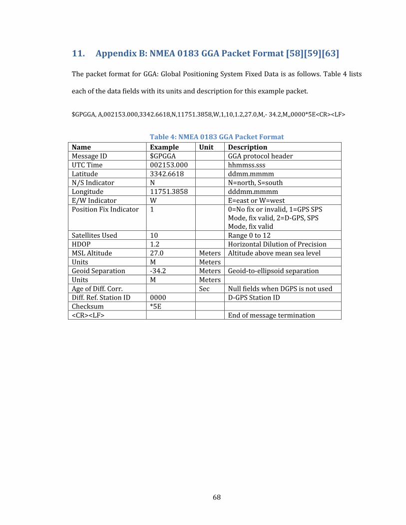
68
11. Appendix B: NMEA 0183 GGA Packet Format [58][59][63]
The packet format for GGA: Global Positioning System Fixed Data is as follows. Table 4 lists
each of the data fields with its units and description for this example packet.
$GPGGA, A,002153.000,3342.6618,N,11751.3858,W,1,10,1.2,27.0,M,- 34.2,M,,0000*5E<CR><LF>
Table 4: NMEA 0183 GGA Packet Format
Name Example Unit Description Message ID $GPGGA GGA protocol header UTC Time 002153.000 hhmmss.sss Latitude 3342.6618 ddmm.mmmm N/S Indicator N N=north, S=south Longitude 11751.3858 dddmm.mmmm E/W Indicator W E=east or W=west Position Fix Indicator 1 0=No fix or invalid, 1=GPS SPS
Mode, fix valid, 2=D-GPS, SPS Mode, fix valid
Satellites Used 10 Range 0 to 12 HDOP 1.2 Horizontal Dilution of Precision MSL Altitude 27.0 Meters Altitude above mean sea level Units M Meters Geoid Separation -34.2 Meters Geoid-to-ellipsoid separation Units M Meters Age of Diff. Corr. Sec Null fields when DGPS is not used Diff. Ref. Station ID 0000 D-GPS Station ID Checksum *5E <CR><LF> End of message termination
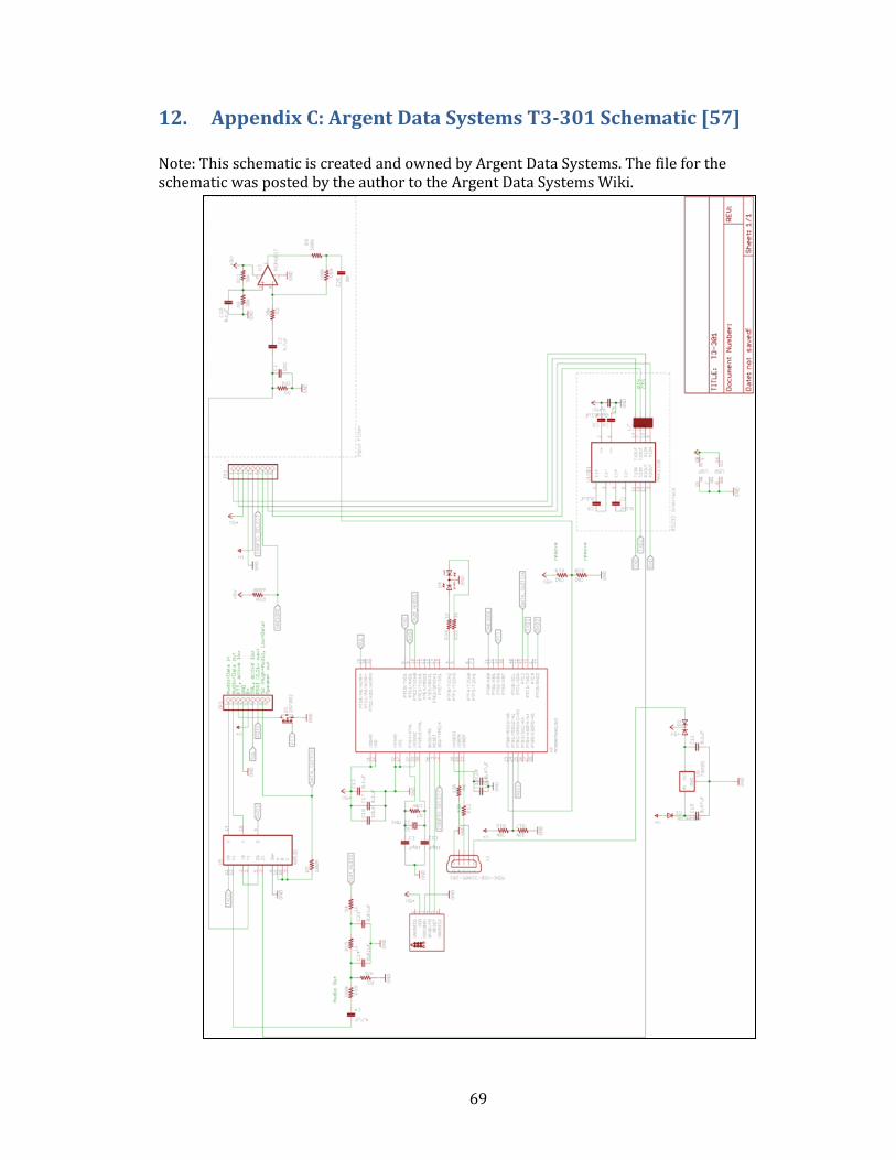
69
12. Appendix C: Argent Data Systems T3-301 Schematic [57]
Note: This schematic is created and owned by Argent Data Systems. The file for the schematic was posted by the author to the Argent Data Systems Wiki.
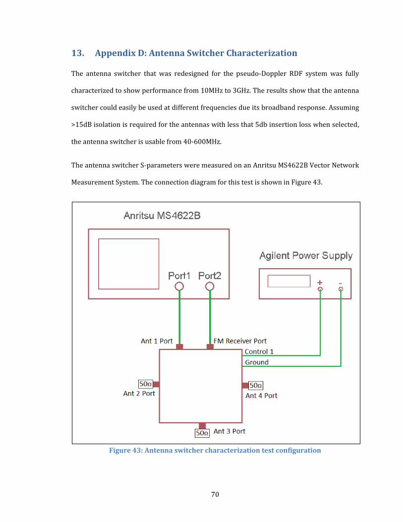
70
13. Appendix D: Antenna Switcher Characterization
The antenna switcher that was redesigned for the pseudo-Doppler RDF system was fully
characterized to show performance from 10MHz to 3GHz. The results show that the antenna
switcher could easily be used at different frequencies due its broadband response. Assuming
>15dB isolation is required for the antennas with less that 5db insertion loss when selected,
the antenna switcher is usable from 40-600MHz.
The antenna switcher S-parameters were measured on an Anritsu MS4622B Vector Network
Measurement System. The connection diagram for this test is shown in Figure 43.
Figure 43: Antenna switcher characterization test configuration
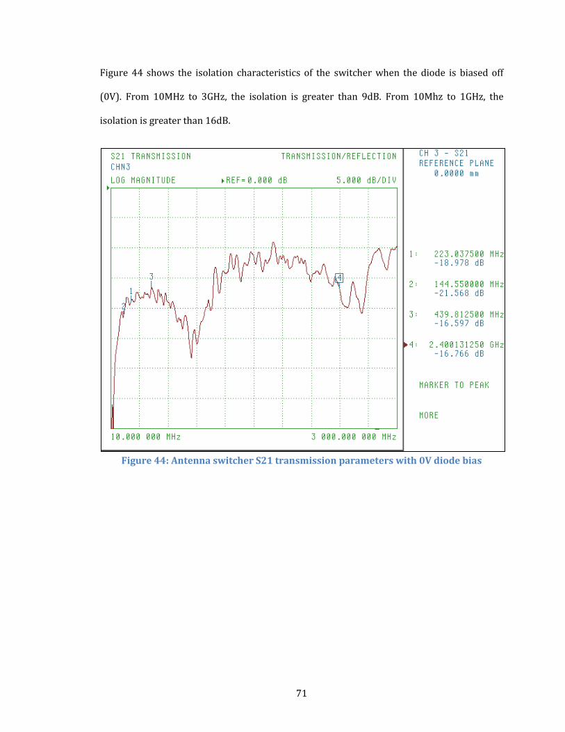
71
Figure 44 shows the isolation characteristics of the switcher when the diode is biased off
(0V). From 10MHz to 3GHz, the isolation is greater than 9dB. From 10Mhz to 1GHz, the
isolation is greater than 16dB.
Figure 44: Antenna switcher S21 transmission parameters with 0V diode bias
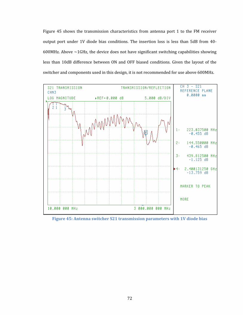
72
Figure 45 shows the transmission characteristics from antenna port 1 to the FM receiver
output port under 1V diode bias conditions. The insertion loss is less than 5dB from 40-
600MHz. Above ~1GHz, the device does not have significant switching capabilities showing
less than 10dB difference between ON and OFF biased conditions. Given the layout of the
switcher and components used in this design, it is not recommended for use above 600MHz.
Figure 45: Antenna switcher S21 transmission parameters with 1V diode bias