Embed Size (px)
Citation preview

THE FINEST RADIO CONTROL MODELS
R
※製品改良のため、予告なく仕様を変更する場合があります。 SPECIFICATIONS ARE SUBJECT TO CHANGE WITHOUT NOTICE. No. 21722(キット)No. 21721(エンジン付半完成キット)
23
4 ~ 56 ~ 24
2526 ~ 35
3637 ~ 4142 ~ 44
目 次 INDEX
INSTRUCTION MANUAL
RADIO CONTROLLED 46 ENGINE POWERED
HELICOPTER
●キットの他にそろえる物 REQUIRED FOR OPERATION●プロポの準備 RADIO PREPARATION● BEFORE YOU BEGIN●本体の組立て ASSEMBLY● OPERATING YOUR MODEL SAFELY●調整・飛行練習・メンテナンス SETTINGS・FLIGHT LESSONS・MAINTENANCE●パーツリスト PARTS LIST●分解図 EXPLODED VIEW●スペアパーツ・オプションパーツリスト SPARE & OPTIONAL PARTS
※ご使用前にこの説明書を良くお読みになり充分に理解してください。Before use, please carefully read the explanations!
組立/取扱説明書
SAFETY PRECAUTIONSThis radio control model is not a toy.
●This is a kind of machine including a rotor which rotates with high speed and has a possibility to be dangerous. You are responsible for this model's assembly, safe operation (place to fly, frequency) check and adjustment of the model.●Assemble this kit only in places out of children's reach!●Take enough safety precaution before and after operation. After every flight, inspect screws and nuts for looseness, and parts for wear. Any damaged parts should be immediately replaced, repaired or adjusted for safe operation.●Use only Kyosho genuine parts for replacement. Failing to do so will result in accidents or malfunction of the model. Kyosho do not take responsibilities for the accidents and crashes if using the parts which are not Kyosho genuine ones.●Always keep this instruction manual ready at hand for quick reference, even after completing the assembly.
© 1997 KYOSHO/禁無断転載複製
この無線操縦模型は玩具ではありません!●高速で回転するローターが付いた危険性のある機械
です。組立て、飛行(場所、電波)、点検、整備はご
自身が責任をもって行ってください。これはあなの
責任です。
●小さい部品が多いので、組立て作業は、必ず幼児の
手がとどかない所で行ってください。
●フライト前、フライト後は必ず、ビスの緩み、各部
品の劣化などを点検し、異常があれば交換・修理・
調整を行い、安全を確認してからご使用ください。
●純正部品以外のパーツを使用しないでください、事
故や不調の原因になるおそれがあります。また、社
外品を使用しての事故、破損等については、一切責
任を負いません、ご了承ください。
●組立て後に、もう一度説明書を見直して下さい。
説明書は、いつでも見られるように大切に保管して
ください。
CONCEPT 46 VR

9711 PRINTED IN JAPAN© 1997 KYOSHO/禁無断転載複製
※製品改良のため、予告なく仕様を変更する場合があります。*SPECIFICATIONS ARE SUBJECT TO CHANGE WITHOUT NOTICE.
京商株式会社
R
THE FINEST RADIO CONTROL MODELS
補足説明書 SUPPLEMENTARY INSTRUCTION SHEET
コンセプト 46 VRCONCEPT 46 VR
取扱説明書に変更があります。組立てる前に必ずこの補足説明書をお読みください。Please use these supplementary instructions in conjunction with the manual included in your kit.
15 Engineエンジン11ページ
カウンターギヤの組立てを
してください。
Assemble the counter gear.
Page 11
32 Tail Pipeテールパイプ取付け19ページ
Page 19
No.21721 / No.21722
3×18mm
3mm
カウンターギヤのバックラッシュがきつい場合は、
3X14mmキャップビスをしめる時に、エンジン全体
を下げながらキャップビス4本をしめて調整してください。
If the backlash is too close, tighten the four pcs. of 3X14mm cap screws as holding the engine downward.
図のギヤを回してみて、テール
ローターが駆動するか確認する。
Rotate the gear and check if the tail rotor rotates.
テールブームは、図の位置まで
必ず差し込む。
Insert the tail boom up to the mark indicated.
3X18mmキャップビス(2本)と、
3mmナイロンナット(2個)が追
加になります。
Ensure to tighten 3X18mm cap screws (2 pcs.) and 3mm nylon nut (2 pcs.) .
約60mmapprox. 60mm
2
3×18mm キャップビス
Cap Screw
2
3mm ナイロンナット
Nylon Nut
3×12mm
3×14mm
3×12mm
3×20mm
3mm 3×14mm
3×12mm
4×5mm
4×5mm
175
55469
58
5756
18
VR-6, VR-B

AA-size Batteries (for transmitter)■単3乾電池(送信機用)
19 ~ 20mm39 ~ 41mm
33 ~ 36mm
2
キットの他にそろえる物(1)REQUIRED FOR OPERATION (1)
2
使用できるサーボサイズSUITABLE SERVOS
エンジンEngine
■グロー燃料
Glow Fuel
●No. 6054 K&B500H燃料
●No. 80701 燃料ポンプ(電動12V)
Fuel Pump (Electric 12V)●No. 80702 燃料ポンプ(手動)
Fuel Pump (Manual)
K&B500H Model Engine Fuel
●No. 96715 ワンタッチプラグヒーター
One-touch Plug Heater
●No. 1791 ブリッツスターターBlitz Starter
●No. 1876/No. 39308 燃料フィルター
Fuel Filter
No. 94402 中強度
Medium Strength
No. 94403 高強度
Hard Strength
●ロックタイト Loctite
1 エンジンヘリ用無線操縦機(プロポ)と電池Radio for engine-powered R/C helicopters, and dry batteries
●このキットにはエンジンヘリ用(5サーボ+
ジャイロ)のプロポが必要です。
●プロポの取扱いは、プロポに付属の説明書
を参考にしてください。
■エンジンヘリ用プロポRadio for engine-powered R/C helicopters
●This kit requires a radio for engine-powered R/C helicopters with 5 servos and 1 gyro.
●For more information on the radio, refer to its explanations.
●半完成キットをお買い求めの方は、エンジンは取付け済です。マフラーは取付けてください。
●With semi-assembled kits, the engine comes pre-installed. Install the muffler.
4 始動用具Required for engine starting: 5 接着剤等
Glues & Lubes
6 さらに用意すると良いものEquipment coming in handy
3 グロー燃料、燃料ポンプGlow Fuel and Fuel Pump
AAAA AAAA
The illustrations showing the radio were taken from the Futaba radio explanations.本説明書のプロポイラストは、Futaba取扱説明書より転載しました。
上空用(ヘリ用)のプロポセットを必ず
使用してください。(上空用以外使用禁止)
CAUTION: Only use a radio for R/C heli-copters! (Any other radio is prohibited!)注意
■ヘリ用46エンジン
■プラグGlow Plug
■プラグヒーターPlug Heater
.46 engine for helicopters
●模型用エンジンは専用のグロー燃料が必要です。ガソリンや灯油は使用できませんので注意してください。また、グロー燃料は揮発性が高く引火しやすいので取扱いには充分注意してください。
●燃料は、ニトロ分10%以上が適しています。
●Engines for R/C models require glow fuel. Do not use gasoline or kerosene; both cannot be used! Also, be very care-ful when han-dling glow fuel which is high-ly inflamma--ble and high-explosive!
●Fuel should contain at least 10% of nitro.
■燃料ポンプ
Fuel Pump
model engine fuel
500H
ガソリンや灯油は使用禁止
WARNING: Gasolineor kerosene cannot
be used!
警告
■スターターStarter ■ネジロック剤
Screw Locking Compound / Screw Cement / Threadlocker
■グリスGrease
■エポキシ接着剤Epoxy Glue
■瞬間接着剤Instant Glue
■スターター用12Vバッテリー12V Battery
■燃料フィルター
Fuel Filter
Grease
Epoxy A
Epoxy B
No. 96506 ボールデフグリス
Ball Diff Grease
クイックタイトジェルボーイGelBoy
●No. 96627
●No. 71481 シールドバッテリー Sealed Battery
(12V-6.5A)
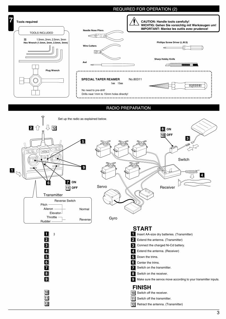
7 組立てに必要な工具Tools required
キットの他にそろえる物(2) REQUIRED FOR OPERATION (2)
3
キットに入っている工具TOOLS INCLUDED
■カッターナイフ Sharp Hobby Knife
■六角レンチ(1.5mm, 2mm, 2.5mm, 3mm) Hex Wrench (1.5mm, 2mm, 2.5mm, 3mm)
■+ドライバー(大、中、小) Phillips Screw Driver (L.M.S)
■ラジオペンチ Needle Nose Pliers
■キリ Awl
■ニッパー Wire Cutters
■プラグレンチ Plug Wrench
プロポの準備 RADIO PREPARATION
スペシャルテーパーリーマー
SPECIAL TAPER REAMER No.80311下穴加工が不要で、直接1mm~15mmの穴あけが
できる工具です。No need to pre-drill! Drills neat 1mm to 15mm holes directly!
●プロポを下の順番にしたがってセットします。Set up the radio as explained below.
ON
OFF
1
アンテナをのばす。(送信機)2
3アンテナをのばす。(受信機)4スロットルのトリムを下げる。5
スイッチを入れる。(送信機)7スイッチを入れる。(受信機)8スティックを動かしてサーボが動いているか確認。9
スイッチを切る。(受信機)10スイッチを切る。(送信機)
アンテナを縮める。(送信機)
11
12
単3乾電池をセットする。(送信機)
充電した受信機用ニカドバッテリーをつなぐ。
●始める時
●終わる時
1
Extend the antenna. (Transmitter)2
3Extend the antenna. (Receiver)4Down the trims.
Center the trims.
5
Switch on the transmitter.7
スロットル以外のトリムを中央にセットする。6 6
Switch on the receiver.8Make sure the servos move according to your transmitter inputs.9
Switch off the receiver.10Switch off the transmitter.
Retract the antenna. (Transmitter)
11
12
Insert AA-size dry batteries. (Transmitter)
Connect the charged Ni-Cd battery.
●START
●FINISH
▲送信機 Transmitter
▲受信機 Receiver
▲スイッチ Switch
▲サーボ Servo
▲ジャイロ Gyro
1
2 12
11
4
3
8 ON
OFF10
●リバーススイッチ Reverse Switchピッチ Pitchエルロン Aileronエレベーター Elevatorスロットル Throttleラダー Rudder
ノーマル Normal
リバース Reverse
6 7
9
5
使用する工具の取扱いには、充分注意してください。CAUTION: Handle tools carefully!WICHTIG: Gehen Sie vorsichtig mit Werkzeugen um!IMPORTANT: Maniez les outils avec prudence!注意

1 組立てる前に説明書を良く読んで、おおよその構造を理解してから組立てに入ってください。Read through the manual before you begin, so you will have an overall idea of what to do.
組立て前の注意(1) BEFORE YOU BEGIN (1)
4
キットの内容をお確かめください。万一不良、不足がありましたら、お買い求めの販売店にご相談いただくか、当社「ユーザー相談室」までご連絡ください。Check all parts. If you find any defective or missing parts, contact your local dealer or our Kyosho Distributor.
2
説明書の見かたHow to read the instruction manual:3
説明書に使われているマークSymbols used throughout the instruction manual, comprise:4
エポキシ接着剤で接着する。
Apply epoxy glue.
瞬間接着剤で接着する。
Apply instant glue (CA glue, super glue).
グリスを塗る。
Apply grease.
ネジロック剤を塗る。
Apply threadlocker (screw cement).
2セット組立てる(例)。Assemble as many times as specified (here: twice).x2
左右同じように組立てる。Assemble left and right sides the same way.
原寸図True-to-scale diagram.
別購入品Must be purchased separately!
仮止め。Tentatively tighten.
2mmの穴をあける(例)。Drill holes with the specified diameter (here: 2mm).
注意して組立てる所。Pay close attention here!
使用する袋詰。
Part bags used.
をカットする。Cut off shaded portion.
2mm
〔 説明例 Example 〕
番号の順に組立てる。Assemble in the specified order.
9 テールTail
HH-2
2
2.6 x 10mm キャップビスCap Screw
1
3 x 3mm セットビスSet Screw
2
2.6mm ナイロンナット
3 x 3mm
テールローターアッセンブリーTail Rotor Assembly
2.6 x 10mm
2.6mm
92
小物部品の名前、原寸図、使用数。Key Number, Part Name, True-to-scale Diagram, Quantity Used
説明書内では多くのマークが使用されています。マークに注意して組立てを進めてください。This instruction manual uses seve-ral symbols. Please note them during the entire assembly.
キット内の部品は、ビス類を除いてキーNo.が付けられています。スペアパーツを購入する時はキーNo.を参照して下さい。All parts except screws are identified by key numbers. For purchasing spare parts, find the key no. of the part needed in the spare part list and refer to the left column to look up the corresponding order no.
Nylon Nut

組立て前の注意(2) BEFORE YOU BEGIN (2)
5
TPビスは、部品にネジを切りながらしめつけるビスです。しめこみが固い場合がありますが、部品が確実に固定されるまでしめこんでください。 ただし、しめすぎるとネジがきかなくなりますので、部品が変形するまでしめないでください。Self-tapping (TP) screws cut threads into the parts when being tightened. Excessive force may
permanently damage parts when tightening TP screws. It is recommended to stop tightening when
the part is attached or when some resistance is felt after the threaded portion enters the plastic.
7
ビスがきかないThe threads are stripped.
しめすぎOvertightened.
Correct
Wrong
キットには、形や長さが違うビスや小物部品が多く入っています。説明書には原寸図がありますので確認してから組立ててください。また、ビス類は多めに入っているものもありますので、予備としてお使いください。This kit contains screws and hardware in different metric sizes and shapes. Before using them, check the screws on the true-to-scale diagrams on the
left side in each assembly step. Some screws are extras.
6
●ビスの種類 SCREWS
ビス Screw
キャップビスCap Screw
TPビスSelf-tapping (TP) Screw
TPサラビスTP F/H Screw
セットビスSet Screw
●小物部品のサイズ例 OTHER HARDWARE
3x12mm ビス Screw
3mm
12mmサラビスFlat Head (F/H) Screw
3mm ワッシャー・ナット Washer・Nut
3mm
5x10mm メタル・ベアリング Metal Bushing・Bearing
5mm
10mm
4mm
E4 Eリング E-ring
●6,000
パーソナルバンドモニターについて ABOUT THE "PERSONAL FREQUENCY MONITOR"
愛機の飛行前に、使うバンドのクリスタルをセットしてスイッチオン! 同一バンドの電波をキャッチするとブザー音とLEDの光で警告。Before operating your helicopter, plug the crystal of your frequency into the Personal Fre-quency Monitor. As soon as you switch it on, you'll know for sure through an interfe--rence signal and LED lamps whether somebody else is on your fre-quency or not! PERSONAL
BAND MONITOR40MHZ
OFF
ONKYOSHO
CORPORATION
No.80591
JRMSA 77KYOSHO CORPRATION
No.80591 (40MHz)No.80592 (72MHz)
専用クリスタル別売Special crystals areavailable at Kyosho!
キット内の部品の中には、組立済みの部品があります。念のためビス等のゆるみが無いか確認してから、組立ててください。Inside the kit, you will find assemblies, i.e. sections that are pre-assembled and hence consist of more than one part. To make sure these assemblies are safely assembled, check among others their screws for looseness. Only then, build in the assemblies.
5

● この取扱説明書は組立キット(No.21722)/エンジン付半完成キット(No.21721)共通の説明書です。 お買い上げいただいた商品に合わせて組立ては以下のようにおこなってください。
組 立 キ ッ ト: ~ 全て
半完成キット: ~ 全て
● This instruction manual is both for kit No.21722 and semi-assembled kit No.21721 with engine.When referring to the instructions for completing the assembly, make the following distinctions.
CONCEPT 46 VR (assembly kit) : All steps from through .
CONCEPT 46 VR (semi-assembled) : All steps from through .
401
4016 23
401
4016 23
グリスを塗る。
Apply grease.
2×8mm サラ小丸ビス
RT/H Screw
2
1
2
使用する袋詰。
Part bags used.
212
421A
2×8mm
128
427
128
201
約30mmapprox. 30mm
1
1
4×5mm セットビス
Set Screw
6×12mm ベアリング
Ball Bearing
2
128
ヒラーコントロールレバーブッシュ
Hiller Control Lever Bushing6
仮止め。
Tentatively tighten.
番号の順に組立てる。
Assemble in the specified order.
VR-A, VR-BローターヘッドRotor Head
VR-A, VR-EローターヘッドRotor Head
左右同じように組立てる。Assemble left and rightsides the same way.
リンケージボール
Linkage Ball
2
212
6
7
2
1
4×5mm
ネジロック剤を塗る。
Apply threadlocker(screw cement).
4
6
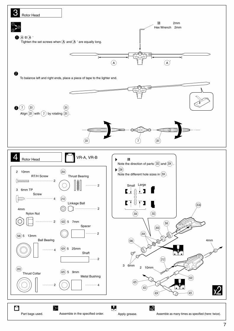
と が平行になるように を動かす。
Align with by rotating .
3
4
使用する袋詰。
Part bags used.
1
番号の順に組立てる。
Assemble in the specified order.
4mm
3×6mm2×10mm
A Ð A ' が同一寸法になる位置でセットビスをしめる。Tighten the set screws when A and A ' are equally long.
2 左右の重さがつり合うまで軽い方にテープを貼る。
To balance left and right ends, place a piece of tape to the lighter end.
3 201 2017
2017
ローターヘッドRotor Head
VR-A, VR-BローターヘッドRotor Head
六角レンチ(2mm)Hex Wrench(2mm)
A A '
2017201
56
204
20356
353A
422
212
425424
425
423
部品の向きに注意。
Note the direction of parts and .203 204
203204
小
Small
大
Large
2×10mm サラ小丸ビス RT/H Screw
2
3×6mm TPビス Screw
4
4mm ナイロンナット Nylon Nut
2
4
2
5×13mm ベアリング Ball Bearing
56
リンケージボール
Linkage Ball212
5×25mm シャフト Shaft
2
5×7mm スペーサー Spacer
2
5×9mm メタル Metal Bushing
4
425
スラストベアリング
Thrust Bearing
2
2
204
スラストカラー
Thrust Collar203
422
424
の穴の大きさに注意。
Note the different hole sizes in .
204
204
201
7
x22セット組立てる(例)。x2Assemble as many times as specified (here: twice).
グリスを塗る。
Apply grease.

5
2.6mm
2.6×12mm
426
2.6mm ナット Nut
8
2.6×12mm ビス Screw
8
VR-AローターヘッドRotor Head
8
12
6
163
10 4.8mm ボールエンド Ball End
4
2×36mm アジャスタブルロッド Adjustable Rod
368
2
2×62mm アジャスタブルロッド Adjustable Rod
10163 368
368
,
163
163
10
x2●スタビコントロールロッド
Stabilizer Control Rod約47mm
approx. 47mm
●ピッチロッド
Pitch Rod
約21.5mm
approx. 21.5mm
●スタビロッド
Stabilizer Rod約22mm
approx. 22mm
ローターヘッドRotor Head VR-A
7 スタビコントロールロッド
Stabilizer Control Rod
スタビロッド
Stabilizer Rod
ピッチロッド
Pitch Rod
ローターヘッドRotor Head
使用する袋詰。
Part bags used.
原寸図
True-to-scale diagram.
2セット組立てる(例)。x2Assemble as many times as specified (here: twice).
左右同じように組立てる。
Assemble left and right sides the same way.

2
8×12mm ベアリング
Ball Bearing
2
2×14mm ピン
Pin
4
3×7mm サラビス
F/H Screw
1
3×18mm キャップビス
Cap Screw
1
3mm ナイロンナット
Nylon Nut
9 VR-D
VR-D, VR-5, VR-6
メインギヤMain Gear
431
59
31
431
431
374
31
59
マストアッセンブリー
Mast Assembly
使用する袋詰。
Part bags used.
仮止め。
Tentatively tighten.
8 VR-B, NE-C, VR-DマストMast
No.96506ボールデフグリスを使用する。150
48
47
46
3×7mm
3mm
3×18mm
451
230
230
33
ネジロック剤を塗る。
Apply threadlocker(screw cement).
212
188
2×8mm
2×8mm212
2
リンケージボール
Linkage Ball212
Eリング E2.0E-ring
2
230
3×14mm シャフト
Shaft1
33
9
2
102×8mm サラ小丸ビス
RT/H Screw
コントロールレバーControl Lever
グリスを塗る。
Apply grease.

1
3×20mm TPビス Screw
3×8mm ワッシャー Washer
11
12 VR-6, VR-B エンジンEngine
使用する袋詰。
Part bags used.
別購入品。
Must be purchasedseparately!
VR-D, VR-5エルロンレバーAileron Lever
ネジロック剤を塗る。
Apply threadlocker(screw cement).
1
2×8mm サラ小丸ビス RT/H Screw
3
3×30mm キャップビス
Cap Screw
1
3.5×14mm キャップビス
Cap Screw
4
リンケージボール Linkage Ball
3
212
8×16mm ベアリング
Bearing
1
49
12×18mm ベアリング
Bearing
2
226
エルロンレバーカラーAileron Lever Collar
1
37
エンジンに付属
Incl.with Engine
3.5×14mm
3×30mm
3mm
エンジン付属
Incl. with Engine.
ロッキングジグ
Locking Jig
エンジン
Engine
ナットをしめる時、エンジンの
シャフトが空回りしないように
固定するジグ。
Use to lock piston while tighteningnut on crank shaft.
49
465
226
226
472
463
385
468
1
3mm ナイロンナット
Nylon Nut
エポキシ接着剤で
接着する。
Apply epoxy glue.
212
2mm
2×10mm
スロットルレバー
2mmの穴をあける(例)。2mm
Drill holes with the specified diameter (here: 2mm).
1
2×10mm サラ小丸ビス
RT/H Screw
1
2mm ナット
Nut
1
リンケージボール
Linkage Ball212
10
2×8mm
2×8mm
2×8mm
3×8mm
3×20mm
212
212
247
479
479
450
37
209
3×12mm
3×20mm
3×20mm キャップビス Cap Screw
2
3×12mm キャップビス Cap Screw
2

3×12mm
3×14mm
3×12mm
3×20mm
3mm 3×14mm
388
479 カウンターギヤアッセンブリー
Counter Gear Assembly
479
388
3×12mm
3×20mm キャップビス Cap Screw
2
4
3×14mm キャップビス Cap Screw
4
3mm ワッシャー Washer
6
3×12mm キャップビス Cap Screw
リンケージボールを穴に入れておく。Insert the ball in the hole.
212
15 エンジンEngine
VR-B, VR-5VR-6
使用する袋詰。
Part bags used.
燃料タンクFuel Tank14 VR-7
13 VR-6ファンケーシングFan Casing
2.6×10mm
エンジンへTo engine
シリコンチューブ(細)
Silicone Tube (thin)
シリコンチューブ(太 140mm)Silicone Tube (thick 140mm)
シリコンチューブ(太 140mm)Silicone Tube (thick 140mm)
マフラーへTo muffler
燃料フィルターを使う
時は、ここに取り付ける。
When using a fuel filter, install here.
5
2.6×10mm TPビス Screw
467
466
393
461
393
393
390
391
115
110
11
17
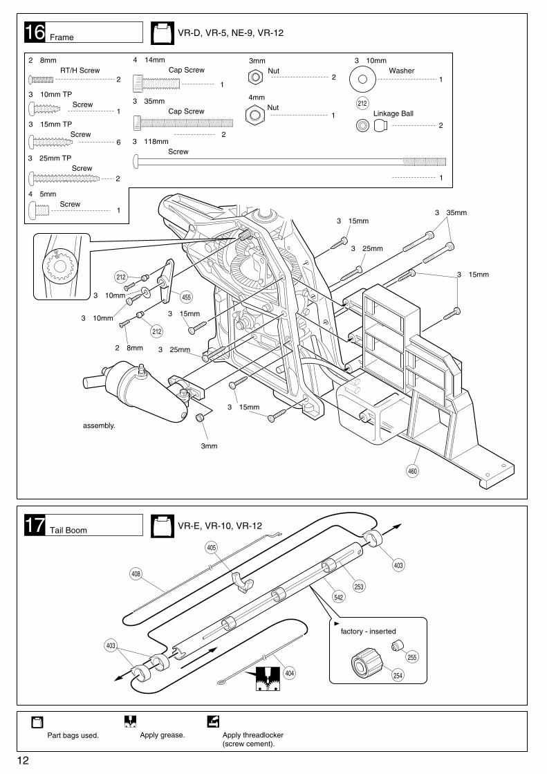
使用する袋詰。
Part bags used.
403
405
408
404
542
403
253
VR-E, VR-10, VR-12テールブームTail Boom
16 VR-D, VR-5, NE-9, VR-12フレームFrame
255
254
取付済factory - inserted
グリスを塗る。
Apply grease.
2×8mm サラ小丸ビス RT/H Screw
2
3×10mm TPビス Screw
1
3×15mm TPビス Screw
6
リンケージボール
Linkage Ball
2
1
1
212
1
4×5mm ビス Screw
1
4×14mm キャップビス Cap Screw
2
3×35mm キャップビス Cap Screw
4mm ナット Nut
2
3mm ナット Nut
3×25mm TPビス Screw
2
3×10mm ワッシャー Washer
3×118mm ビス Screw
1
組み立て済み。
assembly.
▲
12
2×8mm 3×25mm
3×15mm
3×15mm
3×15mm
3×15mm
3×35mm
3×25mm
3mm
3×10mm
212
212
460
4553×10mm
ネジロック剤を塗る。
Apply threadlocker(screw cement).

ネジロック剤を塗る。
Apply threadlocker (screw cement).
2
2
3×4mm セットビス(特殊)
Set Screw (Special type)
3×14mm キャップビス
Cap Screw
2
3×6mm ワッシャー
Washer
19
5×10mm ベアリング
Ball Bearing
4
83
2×8mm ピン
Pin2
180
6×10mm ベアリング
Ball Bearing
2
88
438
83
3×14mm
3×6mm
穴にセットビスをしめこむ。
Fasten both 3X4mm set screwsonto the spots indicated.
逆ネジ
Reverse Screw
180
88
178
538
538 478
91
243
438
使用する袋詰。
Part bags used.
グリスを塗る。
Apply grease.
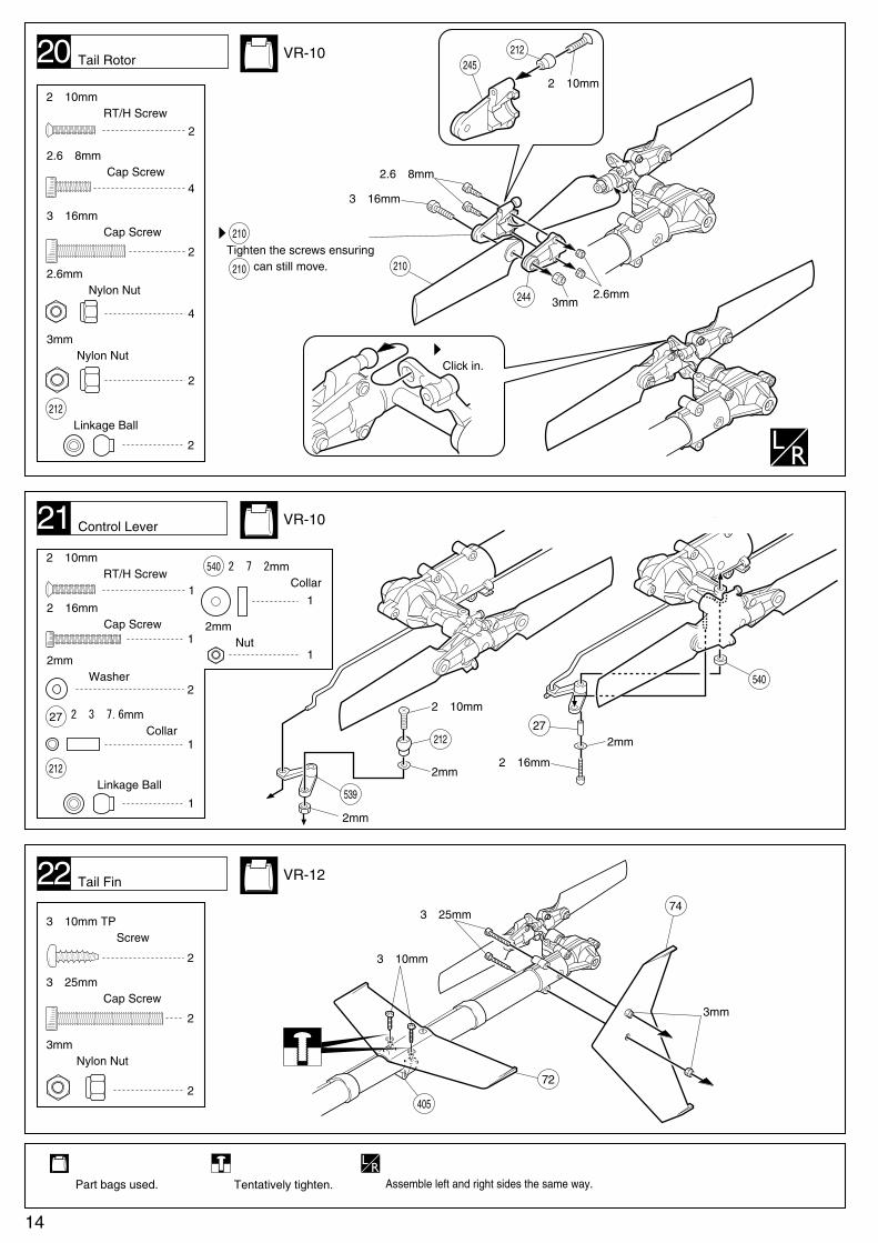
テールローターTail Rotor VR-B, VR-10
2.6mm ナット
Nut
1
2
1
1
2.6×8mm ビス
Screw
2.6×14mm ビス
Screw
3×4mm セットビス
Set Screw
4×5mm セットビス
Set Screw
3
18
3×4mm
5×10mm ベアリング
Ball Bearing
2
83
8×14mm ベアリング
Ball Bearing
2
76
79
8483
537
473
80
2.6mm
4×5mm
2.6×8mm
2.6×14mm
83
81
474
75
76
VR-B, VR-10テールギヤボックスTail Gearbox
2
3
1
1
2×12mm ピン
Pin79
1
5×7×17.4mm カラー
Collar84
平らな面にセットビスを固定する。Filmly tighten the set screws to the flats.
▲
注意して組立てる所。
Pay close attention here!
13
使用する袋詰。
Part bags used.
1
2mm ナット
Nut
1
14
仮止め。
Tentatively tighten.
3×10mm TPビス
Screw
2
3×25mm キャップビス
Cap Screw
2
3mm ナイロンナット
Nylon Nut
2
22
3×10mm
3×25mm
3mm
74
72
405
テールフィンTail Fin VR-12
1
2×16mm キャップビス
Cap Screw
2
2mm ワッシャー
Washer
1
2×3×7.6mm カラー
Collar
21
27
539
212
540
2×16mm
2mm
2mm
2mm
2×10mm
27
コントロールレバーControl Lever VR-10
押し込む。
Click in.
2
2×10mm サラ小丸ビス
RT/H Screw
20
4
2.6×8mm キャップビス
Cap Screw
2
3×16mm キャップビス
Cap Screw
4
2.6mm ナイロンナット
Nylon Nut
2
3mm ナイロンナット
Nylon Nut
1
2×10mm サラ小丸ビス
RT/H Screw
リンケージボール
Linkage Ball
2
212
3×16mm
2×10mm
3mm2.6mm
2.6×8mm
が動く程度にしめる。
Tighten the screws ensuring can still move.
244
210
210
210
212245
テールローターTail Rotor VR-10
リンケージボール
Linkage Ball
1
212
2×7×2mm カラー
Collar540
左右同じように組立てる。
Assemble left and right sides the same way.

3×18mm TPビス
Screw
4
1
1
3×20mm キャップビス(特殊)
Cap Screw(Special type)
3mm ナイロンナット
Nylon Nut
20
2.6×12mm TPビス
Screw
24
25
3×20mm
3mm
スタビコントロールロッド
Stabilizer Control Rod
スタビロッド
Stabilizer Rod
ピッチロッド
Pitch Rod
VR-AローターヘッドRotor Head
VR-8プロポRadio
使用する袋詰。
Part bags used.
左右同じように組立てる。
Assemble left and right sides the same way.
3×8mm TPビス
Screw
2
4
23 スキッドSkid VR-8, VR-11
3×4mm セットビス
Set Screw
15
410
102
103
107
102
181
3×18mm
3×18mm
3×8mm
3×4mm
25mm
96 ピッチサーボ
Pitch Control Servo
ラダーサーボ
Rudder Control Servo
エレベーターサーボ
Elevator Control Servo
2.6×12mm
2.6×12mm
スロットルサーボ
Throttle Control Servo
エルロンサーボ
Aileron Control Servo
各サーボの向きに注意。
Note the direction of each servo.
別購入品
Must be purchased separately!

コード
Cords
97
2
2
4.8mm ボールエンド
Ball End
2×84mm アジャスターロッド
Adjuster Rod
27
使用する袋詰。
Part bags used.
26
541
10
ジャイロアンプ
Gyro Amp
ジャイロ
Gyro
スイッチ
Switch
スイッチ
Switch
ゲインコントローラ
Gain Controller
受信機
Receiver
153
153
受信機は、振動防止のため、スポンジ
等でくるんでから取り付ける。
Wrap the receiver in sponge forprotection against vibration.
ジャイロのケースは、フレームに
接触しないように取り付ける。
Make sure the gyro does notcontact the frame.
コネクターの接続は、プロポ
の説明書に従ってください。
Follow the radio instructionmanual for connecting. 電池
NiCd Battery
153
153
153
152
VR-8エレベーターリンケージElevator Linkage
VR-8, VR-11プロポRadio
別購入品
Must be purchased separately!
2mmの穴をあける(例)。2mm
Drill holes with the specified diameter (here: 2mm).
16
541
10
541541
の取り付け位置
Screw down to thespots indicated.
約2mmapprox. 2mm
約10mmapprox. 10mm
約10mmapprox. 10mm
1.7mm
1.7mm
= にする。
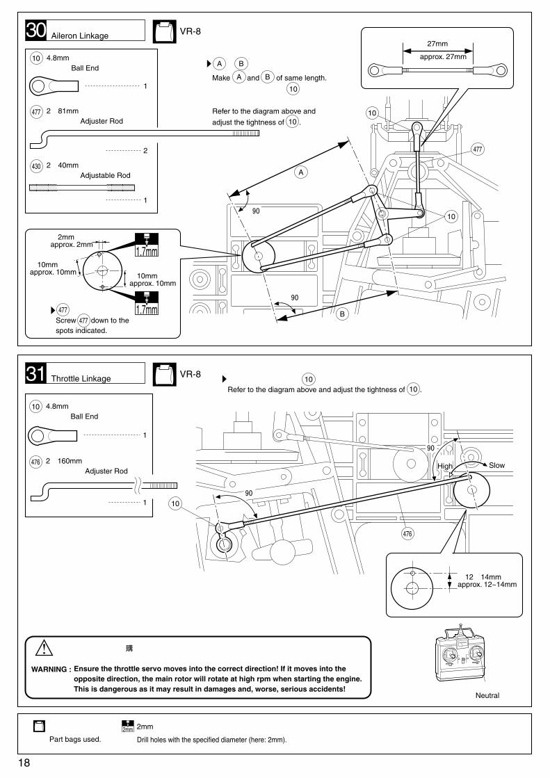
Make and of same length.図のようになるように の
ねじこみ量を調整する。
Refer to the diagram above and adjust the tightness of .
A B
A B10
10A
B10
約90゜
約90゜

28
29
VR-8
1
1
4.8mm ボールエンド
Ball End
2×84mm アジャスターロッド
Adjuster Rod541
10
1
1.7×260mm ロッド
Rod475
Cut off shaded portion.
をカットする。別購入品
Must be purchased separately!
使用する袋詰。
Part bags used.
109
87
6
cm
ピッチリンケージPitch Linkage
VR-8ラダーロッドRudder Rod
54
32
10
中央Neutral
中央Neutral
3×10mm TPビス
Screw1
番号の順に組立てる。
Assemble in thespecified order.
17
122
10
約8~12mmapprox. 8mm~12mm
約78mm
approx. 78mm
平行Parallel
スローLow
ハイHigh
フレームに当る場合は、アジャスターロッドを少し曲げる。
If adjuster rod is interfere with frame, please bend adjuster rod to avoid interfere.
475
4523×10mm
左
Left
約12~14mmapprox. 12~14mm
90°右
Right
12
476
10
図のようになるように のねじこみ量を調整する。
Refer to the diagram above and adjust the tightness of .10
10
約12~14mmapprox. 12~14mm
90゜
90゜
スローSlow
ハイHigh
10
10
477
A
B
約90゜
約90゜
= にする。
Make and of same length.
図のようになるように の
ねじこみ量を調整する。
Refer to the diagram above and
adjust the tightness of .
A B
A B
10
10
の取り付け位置
Screw down to thespots indicated.
477477
約2mmapprox. 2mm
約10mmapprox. 10mm
約10mmapprox. 10mm
1.7mm
1.7mm
約27mm
approx. 27mm
31
使用する袋詰。
Part bags used.
30
1
1
4.8mm ボールエンド Ball End
2×160mm アジャスターロッド Adjuster Rod
476
10
2
1
4.8mm ボールエンド Ball End
2×81mm アジャスターロッド Adjuster Rod
477
10
VR-8エルロンリンケージAileron Linkage
VR-8スロットルリンケージThrottle Linkage
警告
●
WARNING :
1
2×40mm アジャスタブルロッド Adjustable Rod
430
サーボの動作方向に注意する。逆になっていると、エンジンが始動した時に、
メインローターが高回転で回り、事故や破損の原因になります。
Ensure the throttle servo moves into the correct direction! If it moves into theopposite direction, the main rotor will rotate at high rpm when starting the engine.This is dangerous as it may result in damages and, worse, serious accidents! 中央
Neutral
2mmの穴をあける(例)。2mm
Drill holes with the specified diameter (here: 2mm).
18
1
1
3×4mm セットビス
Set Screw
4
2×5mm TPビス
Screw
2
3×10mm TPビス
Screw
33
32
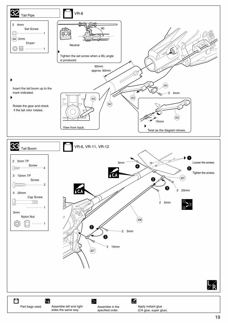
図のギヤを回してみて、テール
ローターが駆動するか確認する。
Rotate the gear and check if the tail rotor rotates.
テールブームは、図の位置まで
必ず差し込む。
Insert the tail boom up to the mark indicated.
図の位置までねじ込む。
Twist as the diagram shows.
3mm
1
3×20mm キャップビス
Cap Screw
1
3mm ナイロンナット
Nylon Nut
407
406
454
3×20mm
2×5mm
使用する袋詰。
Part bags used.
左右同じように組立てる。
Assemble left and rightsides the same way.
2
1
54
3
番号の順に組立てる。
Assemble in thespecified order.
VR-8テールパイプ取付けTail Pipe
VR-6, VR-11, VR-12テールブームTail Boom
2mm ストッパー
Stoper
ゆるめる。
Loosen the screws.
しめる。
Tighten the screws.
瞬間接着剤で接着する。
Apply instant glue(CA glue, super glue).
(後ろからみたところ)
View from back.
453
約60mmapprox. 60mm
3×4mm
454
453
542
15mm453
図のようになる位置でセットビスをしめる。
Tighten the set screw when a 90¡ angle is produced.
90°
中央Neutral
19
4073×10mm
2×5mm2
3
2×5mm TPビス
Screw
5
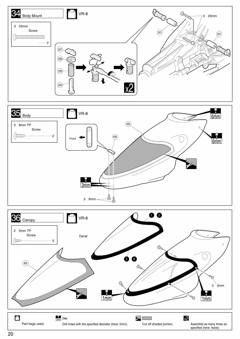
36
3×8mm TPビス
Screw
2
35
使用する袋詰。
Part bags used.
6mm
3mm
6mm
1mm1mm
2mmの穴をあける(例)。2mm
Drill holes with the specified diameter (here: 2mm).
459
458
3×8mm
2×5mm
Cut off shaded portion.
をカットする。
1 2( )
3 4( )
●デカール
Decal
VR-8ボディBody
VR-8キャノピーCanopy
前
Front108
2
3×25mm ビス
Screw
34
241 241
237
238
239
240
3×25mm
x2
VR-8ボディマウントBody Mount
2セット組立てる(例)。x2Assemble as many times as specified (here: twice).
20
38
1
2
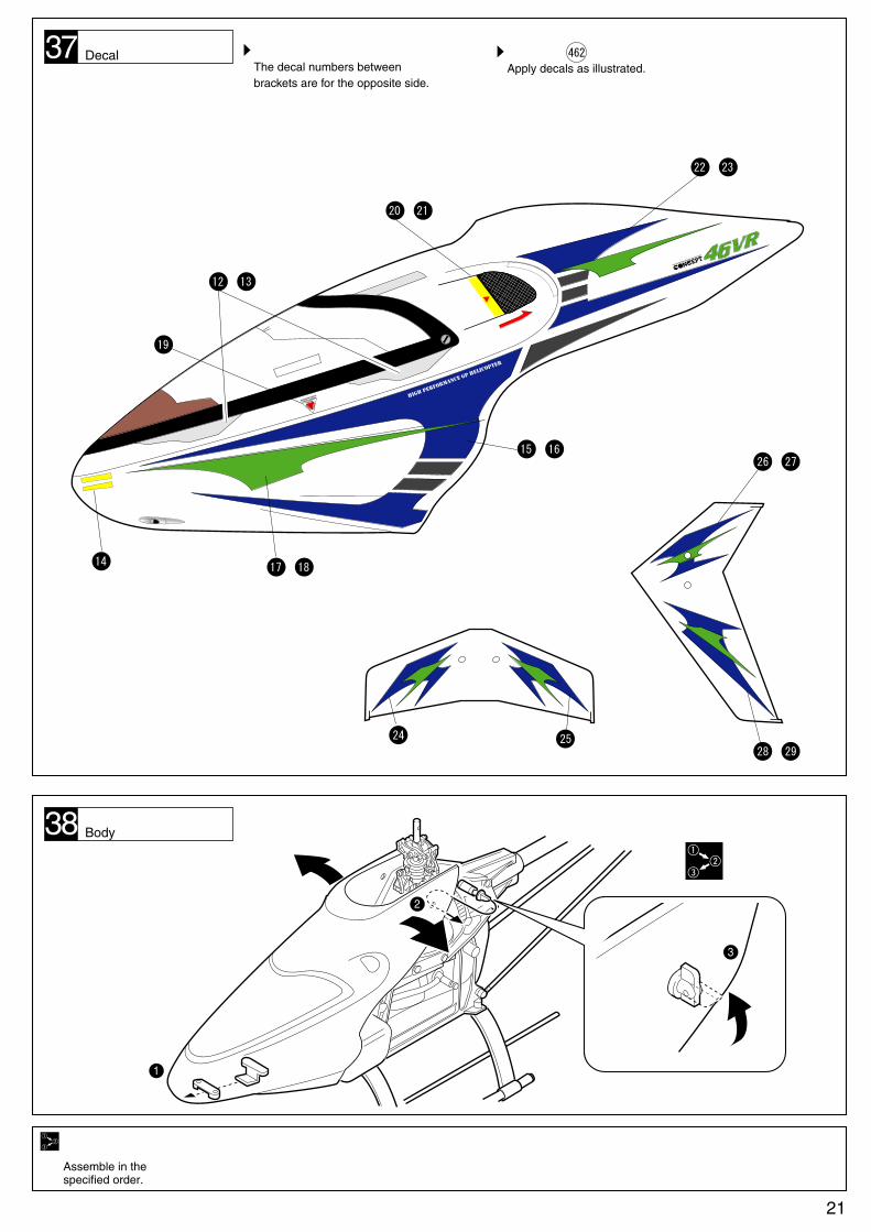
番号の順に組立てる。
Assemble in thespecified order.
ボディBody
図の位置に デカールをはる。
Apply decals as illustrated.37 462カッコの中は反対側用デカールです。
The decal numbers betweenbrackets are for the opposite side.
25
26( )27
28( )29
24
デカールDecal
19
12( )13
20( )21
22( )23
15( )16
1714
( )18
3
21

3×12mm ビス Screw
39
2
2
ドラッグボルト
Drag Bolt
2
4mm ナイロンナット Nylon Nut
40
の接着は確実におこなうこと。
不完全な場合、飛行中の事故につながり、大変危険です。
気温が低い時は、接着部分をドライヤーで温めながら作業すること。
The gluing of and has to be done precisely. Unprecisionwill lead to accidents when flying. If the temperature is low, use a(hair) dryer to warm up the sections for gluing, and glue together.
362
362 363
363
警告
注意
●
●
部のフィルムをカットする。
Trim the shaded portion of the film.
取付位置。
Positions for gluing and .
363
516
437
362
3×12mm
362
362 363
363
向きに注意する。
Note the direction.
516363
362
THE FINEST RADIO CONTROL MODELS
ブレードバランサー
Blade Balancer
デカール
Decal
デカール
Decal
4mm
ローターの取付向きに注意する。
Note the direction of the main rotor blades.
ローターに手で少し力を加えた時、動く程度にビスをしめる。また、左右の締め付けの強さを同じにすること。
Screws should not be fastened either too loose or too tight. Allow for some movement of the blades in the rotor grips.
WARNING :
NOTICE :
VR-AメインローターMain Rotor
NE-FメインローターMain Rotor
437
バランス調整が不完全だと振動の原因
になり、色々なトラブルの原因に
なります。安全のため調整は正確に
おこなってください。
If the main rotor blades are notperfectly balanced, vibration, loosescrews and radio trouble are theconsequences.
軽い方にデカールを貼る。
Attach the tracking tape to the lighter side.
x2
22
別購入品
Must be purchasedseparately!
エポキシ接着剤で
接着する。
Apply epoxy glue.
使用する袋詰。
Part bags used.
2セット組立てる(例)。x2Assemble as many times as specified (here: twice).
別購入品
Must be purchasedseparately!
エポキシ接着剤で
接着する。
Apply epoxy glue.
左右同じように組立てる。
Assemble left and right sides the same way.
使用する袋詰。
Part bags used.
2セット組立てる(例)。x2Assemble as many times as specified (here: twice).

番号の順に組立てる。
Assemble in thespecified order.
PITCH GAUGELOW-PITCH (0û)
HOVER-PITCH (6û)
HI-PITCH (10û)
R
THE FINEST RADIO CONTROL MODELS
0 2 4
6 8 10 0 2 4
6 8 10
PIT.CURVE
HI LOW
PITCH GAUGE LOW-PITCH (0û)
HOVER-PITCH (6û)
HI-PITCH (10û)
R
THE FINEST RADIO CONTROL MODELS
PITCH GAUGELOW-PITCH (0û)
HOVER-PITCH (6û)HI-PITCH (10û)
R
THE FINEST RADIO CONTROL MODELS
0 2 4
6 8 10 0 2 4
6 8 10
PIT.CURVE
HI LOW
1
1
2
3
2
3
41
●ピッチ角の参考値 Pitch reference table メインローターを水平にした状態にて測定する。
メインローターピッチ角●
ハイHigh
ハイピッチHigh Pitch
ホバーピッチHover Pitch
ピッチロッドPitch Rod
中央Neutral
ローLow
ローピッチLow Pitch
スロットルスティックを中央にする。
メインローターにピッチゲージを差し込む。
2本のピッチロッドを調整して、ホバーピッチの線
とスタビライザーバーが平行になるようにする。
スロットルスティックをハイにする。
送信機のピッチカーブ調整でハイピッチを調整する。
スロットルスティックをローにする。
送信機のピッチカーブ調整でローピッチを調整する。
Center the throttle control stick. Slide the pitch gauge onto each blade. Adjust the length of both pitch rods to make the stabilizer bar run parallel to the hover pitch line on the gauge.
Move the throttle control stick to high and set with your transmitter a high pitch.
Move the throttle contol stick to low and set with your transmitter a low pitch.
Main rotor pitch adjustment●
スティック位置Stick Position
ローLow
中央Center
ハイHigh
ホバリング練習
Hovering 0û 6û 10û
上空飛行
Normal Flight -2û 6û 9û
ループ、ストールターン
Loop / Stall Turns -3û 4û 9û
ロール
Roll -6û 2û 9û
3D(アクロバット)フライト
3D (Aerobatics) -8û 0û 9û
オートローテーション
Autorotation -2~ -3û 6û 12û
メインローターMain Rotor
In case of Mode 1
23

42
下記の点をもう一度チェックする。
Check all parts.
ビスなどがゆるんでいないか。
Examine all screws, etc. for theirtightness.
この穴の中のセットビスがゆるむとテールローターが
回りません。飛行の前は必ずチェックする。
The tail rotor will not rotate if the set screw is loose!The tail drive check hole allows you to check the setscrew for proper tightness! Check before evey flight.
1
1
1
送信機のスティックとサーボが
正しく動くか。
Examine sticks and servos foradequate movement.
2
各ロッドはスムースに動くか。
Examine linkage rods for smoothmovement.
3
最終チェックFinal Check
23
24
取扱いの注意 OPERATING YOUR MODEL SAFELY
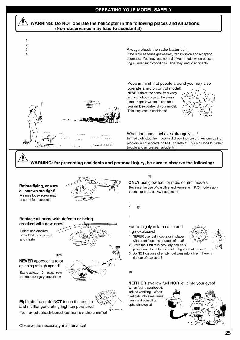
Always check the radio batteries!If the radio batteries get weaker, transmission and reception decrease. You may lose control of your model when opera-ting it under such conditions. This may lead to accidents!
When the model behaves strangely . . .!Immediately stop the model and check the reason. As long as the problem is not cleared, do NOT operate it! This may lead to further trouble and unforeseen accidents!
●周囲に人がいなくて、広い安全な場所で! 1. 近くに小さな子供がいたり、人の多い場所では飛行させない。
2. 民家の近くや公園などでは飛行させない。
3. 室内やせまいところでは飛行させない。。
4. 強風時、雨天時には飛行させない。
※人にケガをさせる原因になります。また、物をこわしたり、
他人の迷惑になります。
●飛行前に、ビス等のゆるみをチェックする。
77
81
●プロポ関係の電池残量は常にチェックする。 電池が減ってくると電波の送・受信が弱くコントロール ができなくなり、墜落や事故の原因になります。
●近くで無線操縦模型を楽しんでいる人がいる。 同じバンドでの同時飛行はできません。電波が混信して
コントロールができなくなり、墜落や事故の原因になります。
ビス1本のゆるみが事故に
つながります。
Before flying, ensure all screws are tight!A single loose screw may account for accidents!
●亀裂や傷のついた部品は、新品と交換する。墜落や事故の原因になります。
Replace all parts with defects or being cracked with new ones!
Defect and cracked parts lead to accidents and crashs!
●回転しているローターには近づかない。接触事故を防ぐために、10m以上機体から離れること。
NEVER approach a rotor spinning at high speed!
Stand at least 10m away from the rotor for injury prevention!
25
WARNING: Do NOT operate the helicopter in the following places and situations: (Non-observance may lead to accidents!)
次のような時、場所では飛行させない。思わぬ事故の原因になります。
警告
WARNING: for preventing accidents and personal injury, be sure to observe the following:事故やケガ等の危険防止のため、次のことを必ずお守りください。
警告
Keep in mind that people around you may also operate a radio control model!NEVER share the same frequency with somebody else at the same time! Signals will be mixed and you will lose control of your model.This may lead to accidents!
●へりの動きがおかしい??とき。 すぐに飛行を中止しておかしい原因を調べる、原因不明のまま
飛行させると、思わぬ故障や事故の原因になります。
10m
●飛行直後は、エンジン、マフラー周辺は高温になって いるので、すぐにはさわらない。
●定められたメンテナンスをおこなう。
ヤケドの原因になります。
Right after use, do NOT touch the engine and muffler generating high temperatures!
Observe the necessary maintenance!
You may get seriously burned touching the engine or muffler!
●燃料は、引火性があります。1. 火気のあるところや室内では絶対に使用しない。
2. 保管は、キャップをしっかりしめ、幼児の手の届かない冷暗
所に置くこと。
3. 使用後の空缶は、火中には投げ入れない。爆発の原因になり
ます。
Fuel is highly inflammable and high-explosive!1. NEVER use fuel indoors or in places with open fires and sources of heat!2. Store fuel ONLY in cool, dry and dark places out of children's reach! Tightly shut the cap!3. Do NOT dispose of empty fuel cans into a fire! There is danger of explosion!
●燃料は、飲んだり、目に入れたりしない。万一、事故が起きた場合は、吐かせる、洗眼する等をした後、
すぐに医師の診察を受けてください。
NEITHER swallow fuel NOR let it into your eyes!When fuel is swallowed, in-duce vomit-ing. When fuel gets into eyes, rinse them and consult an ophthalmologist!
●燃料は、模型用グロー燃料を必ず使用する。ガソリンや灯油の使用は、火災等の事故の原因になります。
ONLY use glow fuel for radio control models!Because the use of gasoline and kerosene in R/C models ac--counts for fires, do NOT use them!

●プロポの操作によるヘリコプターの動きを充分に
理解してから飛行をおこなってください。
Below are listed the reactions of the CONCEPT 46 VR according to your inputs.
ヘリコプターの動き HELICOPTER RESPONSE ヘリコプターの動き HELICOPTER RESPONSEプロポの操作
CONTROL STICK POSITION (MODE 1)
26
プロポのスティックの動きとヘリコプターの運動CONCEPT 46 VR Control Reactions
ハイHigh
スロットルThrottle
エルロンAileron
エレベーターElevator
ラダーRudder
ローLow
右Right
ダウンDown
アップUp
エンジンの回転が上がりメインローターブレードのピッチが大きくなり上昇する。Engine rpm and the main rotor pitch increase. As a result, the helicopter lifts up.
エンジンの回転が下がりメインローターブレードのピッチが少なくなり下降する。Engine rpm and the main rotor pitch decrease. As a result, the helicopter descends.
左Left
右Right
左Left
2
1
左へ移動。
Moves left.
左へかたむく。
Tilts left.
2
1
右へ移動。
Moves right.
右へかたむく。
Tilts right.
1
2
前進または スピードがあれば降下。 Moves forward. With airspeed, the helicopter descends.
1
2
1
2
後進またはブレーキ スピードがあれば上昇。 Loses airspeed or moves backward. With airspeed, the helicopter lifts up.
1
2
1
2
2 1
テールローターのピッチを変えることで機首を左へ振らせる。By changing the tail rotor pitch, the nose moves left.
テールローターのピッチを変えることで機首を右へ振らせる。By changing the tail rotor pitch, the nose moves right.
調整・飛行させる前にかならずお読みください。 Prior to adjusting & operating, observe the following:
●メインローターが回転しますので、調整・飛行は周りに人がいない屋外でおこなってください。WARNING: Always operate the helicopter outdoors out of people's reach as the main rotor rotates at high rpm!
●機体の調整中は、接触事故等を防ぐため、必ず機体から10m以上離れてください。WARNING: While adjusting, stand at least 10 meters apart from the helicopter!
●機体の破損等を防ぐため、スロットルスティックの操作はローから少しずつ上げてください。
For injury prevention, move the throttle control stick only slowly from low to high!
●無線操縦ヘリコプターが初めてという方は、機体の調整等を経験者のアドバイスを受けながら確実に組立ててください。
中途半端な組上がりの機体を飛行させるのは、大変危険です。
Novice R/C helicopter pilots should always seek advice from experienced pilots for hints in assembly and pre-flight adjust- ments! Note that a badly assembled or insufficiently adjusted helicopter is a safety hazard!
●無線操縦ヘリコプターが初めてという方には、単独飛行はできませんので、必ず経験者の指導を受けてください。
In the beginning, novice R/C helicopter pilots should always be assisted by an experienced pilot and never fly alone!
警告
●プロポの電源スイッチを入れる時、または切る時は必ず下記の順番を守ってください。
When switching the radio ON or OFF, always proceed in the following order:
スロットルスティックをいちばん下(ロー)まで下げておく。送信機のスイッチを入れる。受信機のスイッチを入れる。エンジンを始動する。
1
2
3
4
スイッチを入れる時
エンジンを止める。受信機のスイッチを切る。送信機のスイッチを切る。
1
2
3
スイッチを切る時
Position the throttle control stick (transmitter) entirely to low.Switch on the transmitter.Switch on the receiver.Start / Crank the engine.
1
2
3
4
When switching ON:
Stop the engine.Switch off the receiver.Switch off the transmitter.
1
2
3
When switching OFF:
27
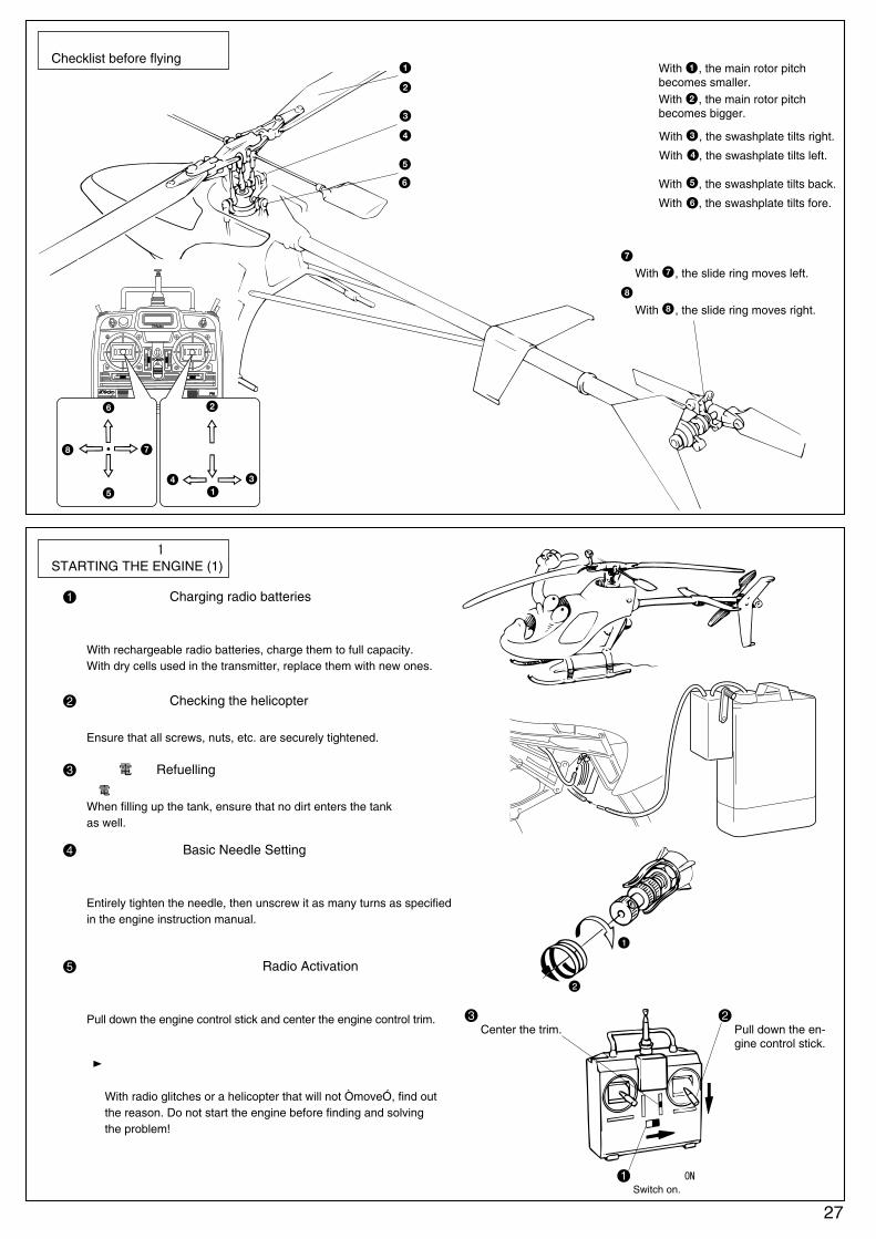
エンジンの始動(1)STARTING THE ENGINE (1)
飛行前のチェックChecklist before flying
With , the main rotor pitch becomes smaller.
でピッチが小さくなる。
でピッチが大きくなる。With , the main rotor pitch becomes bigger.
With , the swashplate tilts back.
でスワッシュプレートが後ろにかたむく。
でスワッシュプレートが前にかたむく。
With , the swashplate tilts fore.
With , the swashplate tilts right.
でスワッシュプレートが右にかたむく。
でスワッシュプレートが左にかたむく。
With , the swashplate tilts left.
でスライドリングが左に移動。
With , the slide ring moves left.
でスライドリングが右に移動。
With , the slide ring moves right.
電池の充電。 Charging radio batteries
プロポの電池は充分に充電しておくこと。送信機に乾電池を
使用している場合は新品に入れかえること。
With rechargeable radio batteries, charge them to full capacity. With dry cells used in the transmitter, replace them with new ones.
1
機体の確認。 Checking the helicopter
ビス類は確実にしまっているか、もう一度確認すること。
Ensure that all screws, nuts, etc. are securely tightened.
2
燃料給油。 Refuelling
給油中はゴミが入らないように注意すること。
When filling up the tank, ensure that no dirt enters the tank as well.
3
ニードル調整。 Basic Needle Setting
エンジンのニードルをいっぱいまでしめてから、指定された量だけゆる
める。(エンジンの取扱いは、エンジン付属の説明書をお読みください。)
Entirely tighten the needle, then unscrew it as many turns as specified in the engine instruction manual.
4
プロポのスイッチを入れる。 Radio Activation
スロットルスティックは、ローにし、スロットルトリムは中央に
する。
Pull down the engine control stick and center the engine control trim.
5
1
2
プロポが誤動作したり動かない場合は、原因を探し、解決する
までエンジンは絶対に始動させない。
With radio glitches or a helicopter that will not ÒmoveÓ, find out the reason. Do not start the engine before finding and solving the problem!
スイッチをON
Switch on.1
スティックを下にPull down the en-gine control stick.
2トリムを中立にCenter the trim.
3

28
エンジンの始動(2)STARTING THE ENGINE (2)
プラグヒート。
プラグヒーターの電池の残量は常にチェックする。
Plug HeatingAlways check the dry batteries used in the plug heater.
6
エンジンを止める時は。
スロットルスティックとトリムを一番下まで下げる。
それでも止まらない時は、燃料パイプをエンジンからぬく。
Engine Stopping
Pull down the engine control stick and the trim.
If the engine still does not stop, pull out the fuel pipe from the engine.
8
エンジン始動。7
エンジンが始動した時にローターが回転しないように、
ローターヘッドを手でしっかり固定する。
When the engine starts, take hold of the rotor head so the rotor blades will not rotate.
スターターが図の方向に回転するか確認する。
(逆に回転する場合は を逆にする)。
Engine StartingEnsure the engine starter is rotating into the direction illustrated.(If rotating into the opposite direction, reverse the and clips.)
トラッキング調整Tracking Adjustment
ピッチロッドPitch Rod
角度が増える。Main rotor pitch increases.
角度が減る。Main rotor pitch decreases.
左右のメインローターブレードのピッチ角をそろえることをトラッキング調整といいます。The tracking adjustment consists in making the main rotor pitch on both blades equal.
●
スロットルスティックを少しずつ上げ機体を真横から見る。Slowly pull up the throttle control stick. Look at the blades directly from the side.
2枚のメインローターが、If both main rotor blades look like in:
のように1枚に見えればOK。
(both blades travel in the same plane), no further adjusting is needed.
のように2枚に見える時は、下記の調整をおこなう。
(both blades track separately), further adjusting is needed.
デカールを貼ったローターを基準にして、もう一方のローターが、Take the blade with the tracking tape as a base.
下に見える時は、ピッチロッドのボールエンドを右に1/2回転回す。
If the other blade (without the tracking tape) tracks lower, rotate the ball end of the pitch rod half a turn right.
上に見える時は、ピッチロッドのボールエンドを左に1/2回転回す。
If the other blade (without the tracking tape) tracks higher, rotate the ball end of the pitch rod half a turn left.
以上の調整を のようになるまでおこなってください。Proceed the same way until both main rotor blades will travel in the same plane as in .
●メインローターが回転しますので、調整・飛行は周りに人がいない屋外でおこなってください。WARNING: Always operate the helicopter outdoors out of people's reach as the main rotor rotates at high rpm!
●機体の調整中は、接触事故等を防ぐため、必ず機体から10m以上離れてください。WARNING: While adjusting, stand at least 10 meters apart from the helicopter!
警告
10m以上10m away

29
ホバリング練習(1)Hover-Lesson 1
トリム調整Trim Adjustment
●浮上する時の機体の傾きは、トリムレバーで調整します。Correct any yawing, rolling or pitching of the helicopter during take offs with the trims.
● 機体が浮上しようとする時、下図の ~ のように傾く時は、送信機のそれぞれのトリムレバーを ~ の方向に調整します。As the engine speed increases and the helicopter is close to taking off,the following tendencies may be noticed for the helicopter to yaw( or ), to roll ( or ) or to pitch ( or ) instead of lifting straight up. If this happens, adjust the different trims on the transmitterso the helicopter lifts straight up.
●ホバリング練習の前に、次のことを覚えておくと、上達が早くなります。Observe the following basics before practicing the hover. It will make things a lot easier!
機体は、風にまっすぐ向けること。Direct the helicopter into the wind.
風 Wind
テール部は見ずに、機首を見ること。Do not watch the tail, watch the nose of the helicopter.
前傾姿勢で着地する。
横風や、追い風は、操縦が難しくなります。With lateral and tail winds, operation becomes difficult.
後ろから着地すると、メインローターや、テールブームが破損しやすくなります。
Nose-in when landingWhen landing, the helicopter should touch ground with the nose first. If touching ground with the tail first, the main rotor or tail boom may be damaged.
調整や練習飛行は、無風または微風の時におこなう。NOTICE: Adjust and practice flying only when there is a weak wind or no wind.注意
●メインローターが回転しますので、調整・飛行は周りに人がいない屋外でおこなってください。WARNING: Always operate the helicopter outdoors out of people's reach as the main rotor rotates at high rpm!
●機体の調整中は、接触事故等を防ぐため、必ず機体から10m以上離れてください。WARNING: While adjusting, stand at least 10 meters apart from the helicopter!
警告

30
ホバリング練習(2)Hover-Lesson 2
ホバリング練習(3)Hover-Lesson 3
●ヘリコプターをホバリングさせるには、常に操縦していることが必要です。操縦している指が、自然に反応するように、根気よく練習してください。Hovering necessitates constant control. Repeat practicing the hover until your fingers get used to doing the controls on the transmitter.
ヘリコプターを風上に向けて置き、その後方に立つ。スロットルスティックを少しずつ上げ、機体が5~10cmぐらい浮上したら、スロットルスティックを少しずつ下げ着陸させる。Direct the helicopter into the wind. Stand behind the helicopter. Raise the throttle control stick a little, making the helicopter hover at a height of 5 ~ 10 cm. Then, decrease engine speed and safely land it.
この練習を繰り返し、高度を少しずつ上げていく。次に浮上したら、前方に着地するように操縦する。Repeat this exercise and by increasing the altitude gradually. Next, try to land the helicopter a little ahead from where you lifted off.
操縦に慣れたら、空中でホバリングできるように練習する。機体が次にどのような動きをするかを考えスティック操作を先へ先へとおこなうと良い。Once you master these basic controls, you can proceed to the hover at higher altitude. You must constantly anticipate into which direction the helicopter may drift and move the control sticks accordingly.
前進Forward
左Left
右Right
後退Backward
●ホバリングさせることができたら、次に、下記の練習をしてください。上空で飛行させる時に必要な練習です。Once you have mastered the hover, proceed to the following exer-cises, proving indispensable for operating a helicopter at higher altitude.
水平移動Horizontal Movement
風Headwind
●メインローターが回転しますので、調整・飛行は周りに人がいない屋外でおこなってください。WARNING: Always operate the helicopter outdoors out of people's reach as the main rotor rotates at high rpm!
●機体の調整中は、接触事故等を防ぐため、必ず機体から10m以上離れてください。WARNING: While adjusting, stand at least 10 meters apart from the helicopter!
警告
●メインローターが回転しますので、調整・飛行は周りに人がいない屋外でおこなってください。WARNING: Always operate the helicopter outdoors out of people's reach as the main rotor rotates at high rpm!
●機体の調整中は、接触事故等を防ぐため、必ず機体から10m以上離れてください。WARNING: While adjusting, stand at least 10 meters apart from the helicopter!
警告
側面ホバリングHover from the side
対面ホバリングHover from the front
10m以上10m away
10m以上10m away
10m以上10m away

31
着陸Landing
上空飛行High Altitude Flight
左旋回の場合は、エルロン・ラダーが逆になる。With left banks, move the aileron and rudder control sticks left.
●上空旋回飛行を練習します。初めのうちは、機速が速くなりすぎないように注意してください。In the beginning , do not fly too fast when practicing banking at high altitude.
右旋回の場合 With right banking:
エルロンで機体を右にかたむける。Tilt the helicopter to the right side using the aileron control stick.
エレべーターをアップ、ラダーを右。Pull up the elevator control stick and move the rudder control stick right.
旋回が終わったら、エレベーター、ラダーをニュートラルにし、エルロンを左にし機体を水平にする。After finishing banking, move the elevator and rudder control sticks back to neutral and the aileron control stick left to bring the helicopter back into horizontal flight.
各舵の大きさは、速度が早くなるほど大きくなる。The higher the airspeed, the more important control movementbecomes. パワー小
Low-throttle風Wind
パワー大High-throttle 風
Wind
エンジンが止まった機体は、すぐに降下してきます。
大きな声で、周囲の人に注意を与えてください。
When the engine stops, the helicopter will immediately start its descent. Warn all people around you to prevent personal injuries.
風向きにより高度が変化するので、スロットルコントロールで高度を一定に保つようにする。Use the throttle control stick to keep the helicopter at a constant altitude which is likely to change according to the wind and its direction.
●着陸は、機体を風にまっすぐ向けておこないます。Land the helicopter into the wind.
●オートローテーション着陸とは、上空でエンジンが止まってしまっても、機体の損傷を最小限におさえられる着陸方法です。Autorotation is a way of safe landing even with engine failure.
● 基本着陸Basic Landing:
● オートローテーション着陸Autorotation Landing:
スロットルスティック
を少しずつ下げる。
Gradually lower the throttle control stick
スロットルスティックを上げる。
Pull up the throttle control stick slightly.
機速がある時は、エレベーターアップでホバリン
グさせるように着陸。
If the heli has too much speed, pull up the elevator control stick to make it momentarily hover and land.
風Headwind
スロットルスティックを一番
下まで下げる。
Bring the throttle control stick down to the lowest position.
機体を水平に保つように操作。
Keep the helicopter in a horizontal flight position.
スロットルスティックを一番上まで上げ、
ホバリングさせるように着陸。
Pull the throttle control stick all the way up, make the helicopter momentarily hover and land it.
資料協力:笹倉新蔵 (株)電波実験社
●メインローターが回転しますので、調整・飛行は周りに人がいない屋外でおこなってください。WARNING: Always operate the helicopter outdoors out of people's reach as the main rotor rotates at high rpm!
●機体の調整中は、接触事故等を防ぐため、必ず機体から10m以上離れてください。WARNING: While adjusting, stand at least 10 meters apart from the helicopter!
警告
10m以上10m away

32
●点検Daily Check
1日の飛行が終了したら、必ず点検してください。 After one day of helicopter flying, be certain to do the following checks!
機体各部の油、汚れ等を拭きとります。
Wipe off any dirt or oil deposits from your helicopter.
●オーバーホールOverhaul約50タンクのフライト毎に全ての部品を点検するオーバーホールをおこない、異常のある部品は新しい物と交換してください。また、大きな
力の加わる部品(メインローター、メインローターヘッド、テールローターセンターハブ)や、駆動系は特に注意して点検整備をおこなって
ください。組立の際は、ネジロック剤を使用してビスが緩まないように確実に固定してください。
After about 50 tanks of flight, a thorough-going overhaul is necessary. Worn components must be replaced. Components being exposed to mechanical stress (main rotor, rotor head, tail rotor center hub) and the drive train must be overhauled in particular and be greased. When reassembling, use screw locking compound on all screws to prevent loosening.
●墜落してしまったときは。If your helicopter crashesメインローターでテールブームをたたいてしまったり、墜落してしまった場合は、機体の各部に大きな力がかかっていますので、充分な
点検整備をおこなってください。
A thorough-going check is also required if your helicopter crashed, the main rotor blades hit the tail boom and other components were exposed to any strong impact.
ボールエンド/リンケージボール
Ball End / Linkage Ballスワッシュプレート
Swashplateギヤ
Gear
ボールベアリング
Ball Bearing
その他 Other Parts
エンジン、ニカドバッテリー、サーボ、ジャイロにも寿命がありますので、点検が必要です。
Since engines, Ni-Cd batteries, servos and gyros also wear down, they require a regularmaintenance and eventually replacement.
オープンタイプ
open-typeシールドタイプ
sealed-type
クラッチ
Clutch燃料チューブ
Fuel Tube
メンテナンス MAINTENANCE
●ビスの緩みや部品の異常がないかチェックしてください。墜落や事故の原因になりますので、 異常のある部品は必ず交換してください。
WARNING: Make sure that all screws are securely tightened and all parts are in best condition! Damaged parts should be immediately replaced by new ones and loose screws retightened. Failing to do so will inevitably result in accidents such as crashs!
警告
●主な消耗部品Wearing Parts
●必ず京商純正部品と交換してください。WARNING: When replacing defect parts with new ones, please only use Kyosho brand genuine parts.
警告
ボールエンドが容易に外れてしまう場合は、ボールエンドを交換する。ボールに傷等がある場合は、ボールを交換する。Replace ball ends if they come easily off. Replace balls with the first signs of scratches.
内部のベアリングに異常がある場合は交換する。前後左右の動きが悪い場合は、ごみを取り、中央のボールに給油する。Replace the swashplate with defect ball bearings. Should the swashplateÕs action not be smooth, clean it and oil the inner balls.
歯が摩耗していたり、変形している場合は交換する。バックラッシュも点検調整する。Replace gears with stripped teeth. On this occasion, ensure correct gear meshing.
滑らかに回転しない場合は交換する。オープンタイプはグリスを注入する。シールドタイプは給油はしない。Replace ball bearings if their action has worsened. Oil open-type bearings. Do not oil sealed bearings.
クラッチが切れなくなったり、つながるタイミングが低回転になった場合は、交換する。Replace the clutch if it does not disen--gage or if it engages at low throttle.
ひび割れ/変形/変質している場合は交換する。Replace with first signs of cracks, defor--mation or quality deterioration.
33
●エンジン Engine
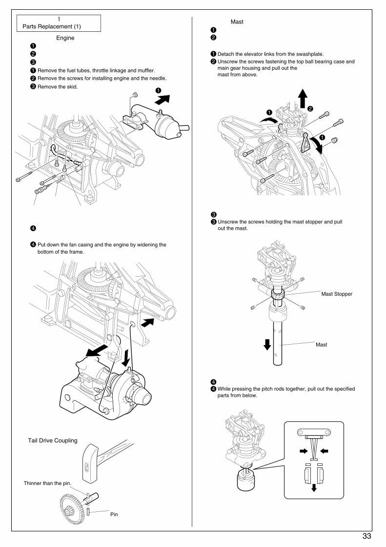
ピンより細い棒Thinner than the pin.
●テールドライブカップリングTail Drive Coupling
●マスト Mast1 エレベーターリンクをスワッシュプレートから外す。2 トップベアリングケース、メインギヤハウジングのビスを外しマスト部を上へ外す。
1 Detach the elevator links from the swashplate.2 Unscrew the screws fastening the top ball bearing case and
main gear housing and pull out the mast from above.
ピッチロッドを内側に曲げながら各部品を下側へ外す。4While pressing the pitch rods together, pull out the specified parts from below.
4
ピンPin
マストストッパーMast Stopper
マストMast
33
燃料チューブ、スロットルリンケージ、マフラーを外す。1
エンジン取付けビス、ニードルを外す。2
スキッドを外す。3
2
Remove the fuel tubes, throttle linkage and muffler.
Remove the screws for installing engine and the needle.
Put down the fan casing and the engine by widening thebottom of the frame.
Remove the skid.3
1
部品の交換(1)Parts Replacement (1)
フレームの下側を少し外して広げながらファンケーシング
と一緒にエンジンを下側に下ろす。
4
4
マストストッパーのビスを外し、マストを引きぬく。
Unscrew the screws holding the mast stopper and pull out the mast.
1
ニードル
スプリング
エンジン取付けビス
2
1
1

34
部品の交換(2)Parts Replacement (2)
●メインギヤのバックラッシュ調整
●テールブーム Tailboom新しいテールブームにシャフトガイドを取付ける際は、下図の
ようなパイプが必要です。シャフトガイドにオイルを塗ると
スムースに入ります。
To insert shaft guides, oil each guide for easier insertion and tap it inside the tailboom using a pipe or dowel.
●マストストッパーの取付位置
●スタビコントロールロッドの長さ調整
スタビライザーバーとミキシングレバーが、平行になるように
ローターヘッドを回転させる。
1
Position of the Mast StopperRotate the rotor head until the stabilizer bar and mixing lever become parallel.
1
ローターヘッドは下へ、マストストッパーは上へ押さえ
ながらマストストッパーの4本のビスを均等に締める。
2
While pressing the rotor head (from above) and mast stopper (from below) together, tighten all 4 screws equally.
2
スタビコントロールロッドの長さが機体に合っていないと、スワッ
シュプレートに無理な力が加わり、スワッシュプレートの破損の
原因になります。ロッドの長さは機体に合わせると同時に、2本の
長さが同じになるように調整してください。
Length of the Stabilizer Control RodsIf both stabilizer control rods do not fit the helicopter, the swash-plate may be damaged due to too much strain. Both rods connect the swashplate with the gear control lever and must be equally long.
550mm
外径13~15mmぐらいのパイプPipe or dowel 13~15mm(outside diameter)
オイルを塗るOil
打ちこみ方向に注意。リヤ側から打ちこむ。Ensure the shaft guides are properly directed when inserting them.
メインギアとピニオンギアとのガタ(バックラッシュ)が多く
なったら下図のようにシムをガタに合わせ、数枚入れて調整し
て下さい。
Main Gear Backlash Adjustment.
180mm360mm
470mm
リヤ側Rear End
スタビライザーバーStabilizer Bar
ミキシングレバーMixing Lever
スタビコントロールロッドStabilizer Control Rod
スワッシュプレートSwashplate
平行Parallel
No. H-3210 8×12mmシム Shim
エンジンマウントEngine Mount
マストストッパーMast Stopper
症 状
浮上しない。メインローターピッチが少ない。
ニードルの開きすぎ。
原 因 対 策
Problem Cause Remedy
35
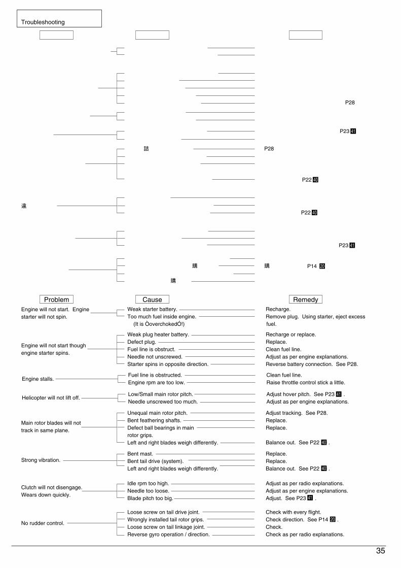
故障?と思う前にTroubleshooting
□ホバリングピッチを調整する。
□エンジンの説明書を読み、調整する。
エンジンが止まってしまう。燃料チューブの詰まり。
エンジンの回転が低すぎる。
□ごみ等が詰まってないか確認する。
□スロットルスティックを少し上げる。
エンジンが始動しない。
(スターターが止まってしまう場合。)スターターのバッテリーが弱い。
エンジン内に燃料が入りすぎている。
(オーバーチョーク)
□スターターのバッテリーを充電する。
□プラグを外し、スターターを使って
エンジン内の燃料を外へ出す。
プラグヒーターのバッテリーが弱い。
プラグの劣化、断線。
燃料チューブの詰まり。
ニードルが開かれていない。
スターターが逆回転している。
□プラグヒーターのバッテリーを充電/交換する
□プラグを交換。
□ごみ等が詰まってないか確認する。
□エンジンの説明書を読み、調整する。
□バッテリーとの接続を逆にする。P28。
トラッキングが合わない。
ピッチ角が合っていない。
フェザリングシャフトの曲がり。
メインローターグリップ部の
ベアリングの劣化。
メインローターバランスが合って
いない。□バランス調整。
□P28 トラッキング調整。□フェザリングシャフトを交換。
□ベアリングを交換。
振動が大きい。
マストの曲がり。
テールドライブシャフトの曲がり。
メインローターバランスが合って
いない。
□マストを交換。
□テールドライブシャフトを交換。
□バランス調整。
アイドリング回転数が高すぎる。
ニードルの緩めすぎ。
メインローターピッチが多い。
□プロポの説明書を読み、調整する。
□エンジンの説明書を読み、調整する。
□ホバリングピッチを調整する。
P23 41
P23 41
P22 40
P22 40
エンジンが始動しない。
(スターターは回る場合。)
ラダーが効かない。
テールドライブジョイントのビスの緩み。
テールローターグリップの向きが逆。
テールリンケージジョイントのビスの緩み。
ジャイロの動作方向が逆。
□フライト毎に確認する。
□向きを確認する。
□確認する。
□プロポの説明書を読み、確認する。
P14 20
Helicopter will not lift off.Low/Small main rotor pitch.Needle unscrewed too much.
□ Adjust hover pitch. See P23 1 .□ Adjust as per engine explanations.
Engine stalls.Fuel line is obstructed.Engine rpm are too low.
□ Clean fuel line.□ Raise throttle control stick a little.
Engine will not start. Engine starter will not spin.
Weak starter battery.Too much fuel inside engine. (It is ÒoverchokedÓ!)
□ Recharge.□ Remove plug. Using starter, eject excess fuel.
Weak plug heater battery.Defect plug.Fuel line is obstruct.Needle not unscrewed.Starter spins in opposite direction.
□ Recharge or replace.□ Replace.□ Clean fuel line.□ Adjust as per engine explanations.□ Reverse battery connection. See P28.
Main rotor blades will not track in same plane.
Unequal main rotor pitch.Bent feathering shafts.Defect ball bearings in main rotor grips.Left and right blades weigh differently. □ Balance out. See P22 0 .
□ Adjust tracking. See P28.□ Replace.□ Replace.
Strong vibration.Bent mast.Bent tail drive (system).Left and right blades weigh differently.
□ Replace.□ Replace.□ Balance out. See P22 0 .
Clutch will not disengage.Wears down quickly.
Idle rpm too high.Needle too loose.Blade pitch too big.
□ Adjust as per radio explanations.□ Adjust as per engine explanations.□ Adjust. See P23 1 .
41
41
40
40
Engine will not start though engine starter spins.
No rudder control.
Loose screw on tail drive joint.Wrongly installed tail rotor grips.Loose screw on tail linkage joint.Reverse gyro operation / direction.
□ Check with every flight.□ Check direction. See P14 .□ Check.□ Check as per radio explanations.
20
クラッチが切れない。
減りが早い。

36
キーNo.Key No. 部品名
袋詰No.Bag No.
使用数 Q'tyDESCRIPTION
467
101827283133374046474849555657585972747576798081838488919697
102103107108110115128129132133137150152153163168172173174175178180181188201203204209210212216226230237238239240241243244245247253254255353A
スタビライザーバー
ヒラーコントロールレバーブッシュ
ヒラーコントロールレバー
4.8mmボールエンド
5x16mmベアリング
2x3mmカラー
2x10mmピン
エレベーターリンク
3x14mmシャフト
エルロンレバーカラー
12x21mmベアリング
ワンウェイシャフト
メインギヤ
メインギヤハウジング
8x16mmベアリング
セカンダリーシャフト
5x13mmベアリング
テールドライブカップリング
2x10mmスプリングピン
2x14mmピン
スタビライザーフィン
バーチカルフィン
テールドライブジョイント
8x14mmベアリング
2x12mmピン
テールギヤボックス(R)
テールギヤボックス(L)5x10mmベアリング
5x7mmカラー
6x10mmベアリング
スライドブッシュ
サーボセットプレート
ワイヤークランプ
スキッドキャップ
アンテナパイプ
ボディキャッチ(A)ボディキャッチ(B)タンクウェイト
シリコンチューブ(細)
6x12mmベアリング
3x6mmベアリング
3x4mmカラー
3x5mmワッシャー(銀)
10x15mmベアリング
C型止め輪
ゴムバンド
両面テープ
2x36mmアジャスタブルロッド
サイクリックレバー
ピッチスライダー
ピッチスライドリング
ピッチスライドリングナット
ベベルピニオンギヤ
テールピッチヨーク
2x8mmピン
ブレース
ピッチレバー
スタビライザーブレード
スラストカラー
スラストベアリング
クラッチライニング
テールローターブレード
リンケージボール
スワッシュプレート
ベアリング
Eリング E2.0ボディマウント(A)ボディマウント(B)ボディマウントスプリング
ボディマウント(C)
ボディマウント(D)
テールセンターハブ
テールローターグリップ(B)テールローターグリップ(A)エルロンレバー
テールドライブパイプ
シャフトガイド(A)シャフトガイド(B)メインローターグリップ
Stabilizer BarHiller Control Lever BushingHiller Control Lever4.8mm Ball End5 x 16mm Ball Bearing2x3mmCollar
2 x 10mm PinElevator Link3 x 14mm ShaftAileron Lever Collar12 x 21mm Ball BearingOneway ShaftMain GearMain Gear Housing8 x 16mm Ball BearingSecondary Shaft5 x 13mm Ball BearingTail Drive Coupling2 x 10mm Spring Pin2 x 14mm PinStabilizer FinVertical FinTail Drive Joint8 x 14mm Ball Bearing2 x 12mm PinTail Gearbox (R)Tail Gearbox (L)5 x 10mm Ball Bearing5 x 7mm Collar6 x 10mm Ball BearingSlide BushingServo Set PlateWire HolderSkid CapAntenna PipeBody Catch (A)Body Catch (B)Tank WeightSilicone Tube (Thin)6 x 12mm Ball Bearing3 x 6mm Ball Bearing3 x 4mm Collar3 x 5mm Washer (Silver)10 x 15mm Ball BearingC Stopper RingRubber BandDouble-sided Tape2 x 36mm Adjustable RodCyclic LeverPitch SliderPitch Slide RingPitch Slide Ring NutBevel Pinion GearTail Pitch Yoke2 x 8mm PinBracePitch LeverStabilizer BladeThrust CollarThrust BearingClutch LiningTail Rotor BladeLinkage BallSwashplateBall BearingE-ring E2.0Body Mount (A)Body Mount (B)Body Mount SpringBody Mount (C)Body Mount (D)Tail Center HubTail Rotor Grip (B)Tail Rotor Grip (A)Aileron LeverTail Drive PipeShaft Guide (A)Shaft Guide (B)Main Rotor Grip
VR-EVR-AVR-A
VR-08,VR-AVR-BVR-10NE-CVR-DVR-DVR-DNE-CVR-DVR-DVR-DVR-BVR-6VR-BVR-6VR-6VR-DVR-12VR-12VR-10VR-BVR-10VR-10VR-10VR-BVR-10VR-BVR-10VR-8VR-8VR-11VR-EVR-8VR-8VR-7VR-7VR-BNE-CNE-CNE-CNE-CVR-DVR-11VR-11VR-ANE-CNE-CNE-CNE-CVR-6VR-10VR-10VR-11VR-DVR-AVR-AVR-BVR-6VR-10
NE-CVR-6VR-DVR-8VR-8VR-8VR-8VR-8VR-10VR-10VR-10VR-DVR-EVR-EVR-EVR-A
111
22212211111121511211121116121
10241111128482111421111122122212
261222222212211332
キーNo.Key No. 部品名
袋詰No.Bag No.
使用数 Q'tyDESCRIPTION
361362363364366367368374385388390391393397398399400401402403404405406407408410
421A422423424425426427428429430431434437438450451452453454455458459460461462463465466467468469472473474475476477478479516533537538539540541542
サイクリックレバーリンク
ルートエンド(A)ルートエンド(B)マスト
ピッチロッドガイド
マストストッパー
2x62mmアジャスタブルロッド
エレベーターアーム
スターターコーン
アッパーベアリングケース
タンクニップル
タンクグロメット
シリコンチューブ(太)
マフラー(A)マフラーバッフル
マフラー(B)マフラーOリング(S)マフラーOリング(L)マフラーニップル
ロッドガイド
テールドライブシャフト
テールサポートブラケット
テールサポートパイプ
テールサポートエンド
1.7x585mmロッド
スキッド
スタビライザーシーソー
5x7mmスペーサー
フェザリングシャフト
5x25mmシャフト
5x9mmメタル
ローターヘッド(B)ローターヘッド(A)ミキシングベース
ピッチロッド
2x40mmアジャスタブルロッド
8x12mmベアリング
ミキシングレバー
ドラッグボルト
3x4mmセットビス(特殊)
メインフレーム (L) VR
メインフレーム (R) VR
テールPPロッドガイド
テールPPロッドジョイント
テールPPロッドストッパー
エレベータレバー
キャノピー (VR)
ボディ(VR)
サーボフレーム (VR)
燃料タンク
デカール (VR)
クーリングファン
エンジンマウント (46VR)ファンケーシング (L) (46VR)ファンケーシング (R) (46VR)ドライブギヤ 28T (46VR)カウンターギヤ 57T (46VR)ワンピースクラッチ (46VR)テールインプットギヤ 16T
テールアウトプットギヤ 18T
2x260mmアジャスターロッド
2x160mmアジャスターロッド
2x81mmアジャスターロッド
テールピッチリング(ボールタイプ)
インサートナット (S)メインローター(4LD)
マニホールド
テールアウトプットシャフト
テールロッドエンド
テールピッチレバー
2x7x2mmカラー
2x84mmアジャスターロッド
テールブーム (BK)
Cyclic Lever LinkRoot Cover (A)Root Cover (B)MastPitch Rod GuideMast Stopper2 x 62mm Adjustable RodElevator ArmStarter ConeUpper Ball Bearing CaseTank NippleTank GrommetSilicone Tube (Thick)Muffler (A)Muffler BaffleMuffler (B)Muffler O-ring (S)Muffler O-ring (L)Muffler NippleRod GuideTail Drive ShaftTail Support BracketTail Support PipeTail Support End1.7 x 585mm RodSkidStabilizer Seesaw5 x 7mm SpacerFeathering Shaft5 x 25mm Shaft5 x 9mm Metal BushingRotor Head (B)Rotor Head (A)Mixing BasePitch Rod2 x 40mm Adjustable Rod8 x 12mm Ball BearingMixing LeverDrag Bolt3 x 4mm Set Screw (Special Type)Main Frame (L) VRMain Frame (R) VRTail PP Rod GuideTail PP Rod JointTail PP Rod StopperElevator LeverCanopy (VR)Body (VR)Servo Frame (VR)Fuel TankDecal (VR)Cooling FanEngine Mount (46VR)Fan Casing (L) (46VR)Fan Casing (R) (46VR)Drive Gear 28T (46VR)Counter Gear 57T (46VR)One-piece Clutch (46VR)Tail Input Gear 16TTail Output Gear 18T2 x 260mm Adjuster Rod2 x 160mm Adjuster Rod2 x 81mm Adjuster RodTail Pitch Ring (Ball-type)Insert Nut (S)Main Rotor(4LD)Mani foldTail OutPut ShaftTail Rod EndTail Pitch Lever2 x 7 x 2 mm Collar2 x 84mm Adjuster RodTail Boom (BK)
NE-CVR-11VR-11NE-CNE-CNE-CVR-AVR-DVR-6VR-6VR-7VR-7VR-7NE-9NE-9NE-9NE-9NE-9NE-9
VR-12VR-EVR-12VR-EVR-11VR-EVR-11VR-AVR-AVR-AVR-AVR-BVR-AVR-ANE-CNE-CVR-8VR-BNE-CVR-AVR-10VR-5VR-5VR-8VR-8VR-8VR-D
VR-12VR-7
VR-6VR-6VR-6VR-6VR-6VR-6VR-6
VR-10VR-10VR-8VR-8VR-8
VR-10VR-5NE-FNE-9
VR-10VR-10VR-10VR-10VR-8VR-E
2221112112112111111311241212224111212222111111111111111111111221621121131
パーツリスト PARTS LIST

EA
B
E
D
C
A
B
E
D C
212
362
516
363
H-3365
3x12mm
4 H-3063
3x6mm
4mm
56 H-3006
204 203
H-3241
4mm
437 1192
353A 212
H-3320A
424422 423 425
H-3302
Z-8007
2x10mm
128 H-3101
212 421
H-3301A2x8mm
3x20mm
2.6mm
3mm
6 7
H-3003 4x5mm
426 H-3303
427 H-3303
2.6x12mm
201 H-3239
428
429
H-3304
10
10
163
H-3503
10
10
163H-3503
28 434132133 133361 212
H-3307
H-3309
3x13mm
3x13mm
129 H-3103
129 H-3103
168212133 132 133
H-3307
2x8mm
2x8mm
10
10
368
H-3503 216
H-3242
2x8mm
10
10
430
H-3503
< EXPLODED VIEW (1) >
37
F
F
G
G
H
I
I
H
364 H-3321
366 H-3323
388 H-3344
40
H-3501
H-3016
367 H-3324
431 PI-15
31
175
479150
H-3248
48
46
H-3021
H-3020
H-3020H-3506
47 H-3019
H-3025
H-6034
477
469
465
H-350854( H-3024)
464( H-3521)
172
H-3106173
174
137
137
59
374
18 H-6033-2
H-300656
55
57
58
H-3503
H-3502
H-3503
37
10
212
H-3122
188
212
H-3501
212
212
212
455
541
541
H-3503
H-3503
H-3503
H-3502
10
10
4x5mm
3x12mm
3x12mm
3x18mm
3x20mm
2x8mm
3x12mm
3x12mm
3mm
3x20mm
3x20mm
3x14mm
3x14mm
2x8mm
2x10mm
2x10mm
H-3510
450 H-3514
451 H-3514
49 H-3016
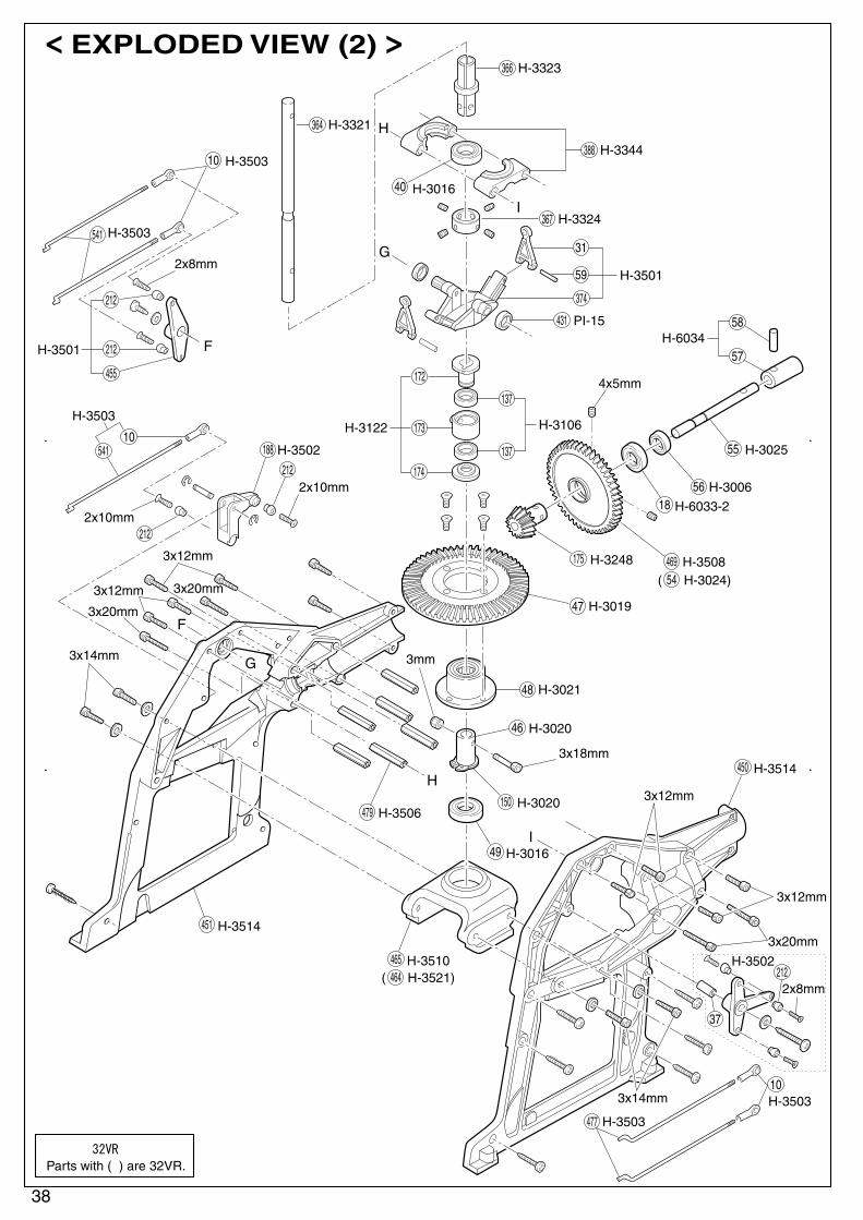
( )は32VRの場合
Parts with ( ) are 32VR.
< EXPLODED VIEW (2) >
38

J
J
K
K
10
96781
H3503H3513
H3222
H3511
H3511
H3509
H3507
H3222
H3512
397
402
400
393
390391
226
476
472
463
385
H3513466
468
226
115
110
461
467
533
398
399
401
3x30mm
2x10mm
3x35mm
3.5x14mm
3mm
2mm
4x14mm
3mm
3mm
4mm
3x118mm
456( H-3522)
227( H-3073)
208( H-3221)
457( H-3522)
( )は32VRの場合
Parts with ( ) are 32VR.
< EXPLODED VIEW (3) >
39

458 H-3518
2x5mm
3x8mm
459 H-3517
450 H-3514451 H-3514
108 H-3054
360 H-3515
103 H-3064
410 181 102
H-3338
96 H-3055
153 H-3072
107 H-3054
97 H-3055
152
237 1806238
239240
241
3x8mm
3x18mm
3x18mm3x4mm
3x15mm
3x15mm
3x25mm
3x25mm
3x4mm
2.6x12mm
< EXPLODED VIEW (4) >
40

M
M
N
N
L
L
Q
Q
180 538
478
178
H-3376
H-3505
88 H-3048
76 H-3040
H-3376
83 1901
91
H-3504
74 H-3039
537
473474
H-3375
80 H-3042
81 H-3042
83 1901
83 1901
84 H-3376
72 H-3039
542 H-3266
210 H-3243
245 H-6054
3x16mm2.6x8mm
3x14mm3x6mm
3mm2.6mm
2x16mm
3x20mm
2x5mm
2x5mm
3x10mm
3x25mm
2.6x14mm
4x5mm
3x4mm
2.6mm
3mm
2.6x8mm
3x10mm
3mm
2x6mm2mm
2x10mm
244 H-6054
243
438H-6053R
212 Z-8007
405 H-3333
254255
H-3277
H-3516253 H-3278
403
452
475
454453
H-3347
404 H-3348
408 H-3516
407
406
407
H-3336
75 H-6047
79 H-3375
27539
540
H-3376212
2mm
2×10mm
< EXPLODED VIEW (5) >
41
H3320AメインローターグリップMain Rotor Grip 212 353A 130900x 2
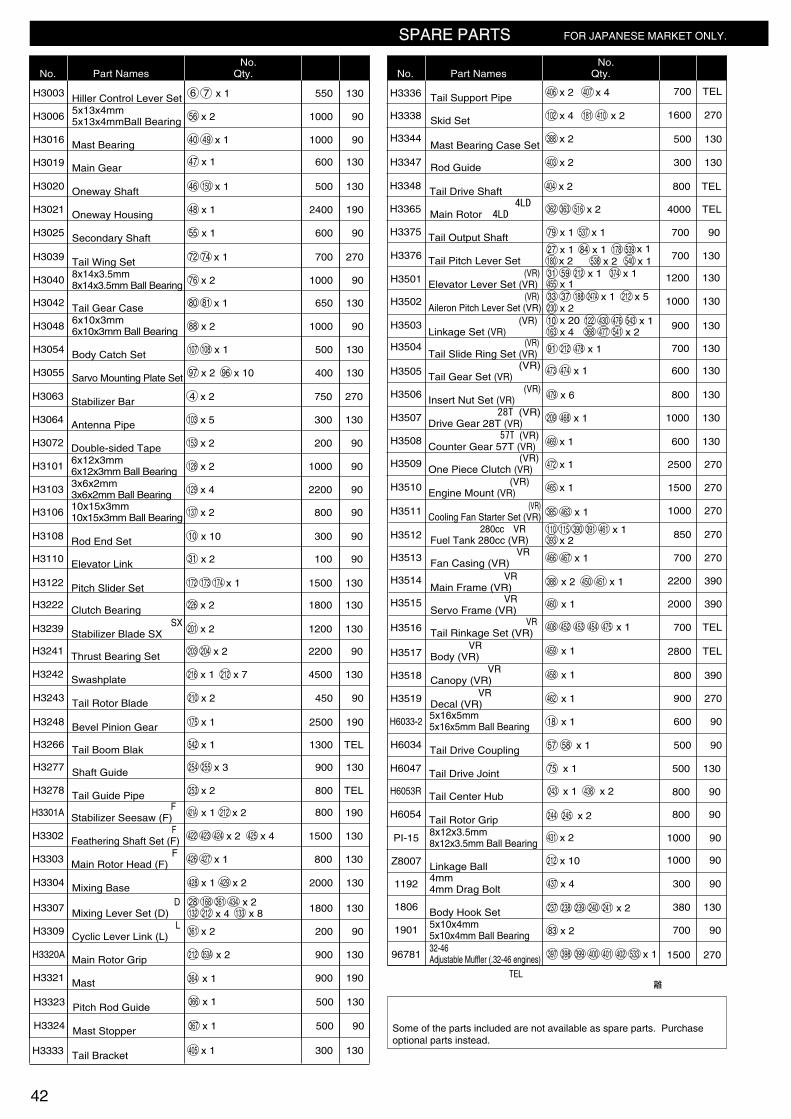
スペアパーツ SPARE PARTS
品番No.
パーツ名Part Names
内容(キーNo.と入数)Qty. ★定価 ★送料
★ FOR JAPANESE MARKET ONLY.
H3003ヒラーコントロールレバーセットHiller Control Lever Set 6 7 130550x 1
H30065x13x4mmベアリング5x13x4mmBall Bearing 56 901000x 2
H3016マストベアリングMast Bearing
H3019メインギヤMain Gear
40 49 901000x 1
H3020ワンウェイシャフトOneway Shaft 46 150 130500
130600
x 1
H3021ワンウェイハウジングOneway Housing 48 1902400x 1
47 x 1
H3039尾翼セットTail Wing Set 72 74 270700x 1
H3025セカンダリーシャフトSecondary Shaft 55 90600x 1
H30408x14x3.5mmベアリング8x14x3.5mm Ball Bearing 76 901000x 2
H3042テールギヤケースTail Gear Case 80 81 130650x 1
H30486x10x3mmベアリング6x10x3mm Ball Bearing 88 901000x 2
H3054ボディキャッチセットBody Catch Set 107 108 130500x 1
H3055サーボセットプレートセットSarvo Mounting Plate Set 97 130400x 2 96 x 10
H3063スタビライザーバーStabilizer Bar 4 270750x 2
H3064アンテナパイプAntenna Pipe 103 130300x 5
H3072両面テープDouble-sided Tape 153 90200x 2
H31016x12x3mmベアリング6x12x3mm Ball Bearing 128 901000x 2
H31033x6x2mmベアリング3x6x2mm Ball Bearing 129 902200x 4
H310610x15x3mmベアリング10x15x3mm Ball Bearing 137 90800x 2
H3307ミキシングレバーセット(D)Mixing Lever Set (D)
28 168 361 4341301800
x 2132 212 x 4 133 x 8
H3239スタビライザーブレード SXStabilizer Blade SX 201 1301200x 2
H3277シャフトガイドShaft Guide 254 130900255 x 3
H3278テールガイドパイプTail Guide Pipe 253 TEL800
800
x 2
H3243テールローターブレードTail Rotor Blade 210 90450x 2
H3266テールブームブラックTail Boom Blak 542 TEL1300x 1
H3301Aスタビライザーシーソー(F)Stabilizer Seesaw (F) 421A 190x 1 212 x 2
H3222クラッチベアリングClutch Bearing 226 1301800x 2
H3122ピッチスライダーセットPitch Slider Set 1301500172 173 174 x 1
H3108ロッドエンドセットRod End Set 9030010 x 10
H3110エレベーターリンクElevator Link 9010031 x 2
H3309サイクリックレバーリンク(L)Cyclic Lever Link (L) 361 90200x 2
H3302フェザリングシャフトセット(F)Feathering Shaft Set (F) 422 423 424 1301500x 2 425 x 4
H3303メインローターヘッド(F)Main Rotor Head (F) 130800426 427 x 1
H3304ミキシングベースMixing Base 428 1302000x 1 429 x 2
品番No.
パーツ名Part Names
内容(キーNo.と入数)Qty. ★定価 ★送料
91 212 478 x 1
473 474 x 1
209 468 x 1
479 x 6
469 x 1
472 x 1
465 x 1
385 463 x 1
466 467 x 1
388 x 2
460 x 1
459 x 1
458 x 1
462 x 1
18 x 1
408 452 453 454 475 x 1
450 451 x 1
燃料タンク 280cc(VR)Fuel Tank 280cc (VR)
110 115
362 363
390 391 461
2702500
2701500
2701000
270850
270700
3902200
3902000
TEL700
TEL2800
390800
270900
90600
90500
x 1393 x 2
メインフレーム(VR)Main Frame (VR)
ファンケーシング(VR)Fan Casing (VR)
サーボフレーム(VR)Servo Frame (VR)テールリンケージセット(VR)Tail Rinkage Set (VR)ボデイ(VR)Body (VR)キャノピー(VR)Canopy (VR)デカール(VR)Decal (VR)
H3347
H3336
H3338
H3344
ロッドガイドRod Guide
テールサポートパイプTail Support PipeスキッドセットSkid SetマストベアリングケースセットMast Bearing Case Set
403 130300
TEL700
2701600
130500
x 2
406 x 2
388 x 2
102 x 4 181 410 x 2
407 x 4
H3348 テールドライブシャフトTail Drive Shaft 404 TEL800x 2
テールドライブカップリングTail Drive Coupling 57 58 x 1
H6047
H6054
テールドライブジョイントTail Drive Joint 75 130500x 1
H6053RテールセンターハブTail Center Hub 243 90800
90800
x 1 438 x 2
テールローターグリップTail Rotor Grip 244 245 x 2
H3375 テールアウトプットシャフトTail Output Shaft 79 90700x 1
27 x 1 84 x 1
537 x 1
31 59 x 1 374212 x 1455 x 1
x 133
10
37 188 247A
x 1476 543430122230 x 2
163 x 4 541477368 x 2x 20
212 x 5
H3376テールピッチレバーセットTail Pitch Lever Set
リンケージセット (VR)Linkage Set (VR)テールスライドリングセット (VR)Tail Slide Ring Set (VR)テールギヤセット (VR)Tail Gear Set (VR)インサートナットセット (VR)Insert Nut Set (VR)
H3501
H3502
H3503
H3504
H3505
H3506
ドライブギヤ 28T (VR)Drive Gear 28T (VR)
H3507
カウンターギヤ 57T (VR)Counter Gear 57T (VR)
H3508
ワンピースクラッチ (VR)One Piece Clutch (VR)
H3509
エンジンマウント (VR)Engine Mount (VR)
H3510
クーリングファンスターターセット (VR)Cooling Fan Starter Set (VR)
H3511
H3512
H3513
H3514
H3515
H3516
H3517
H3518
H3519
H6034
H6033-2
エレベーターレバーセット (VR)Elevator Lever Set (VR)エルロンピッチレバーセット (VR)Aileron Pitch Lever Set (VR)
130700
1301200
1301000
130900
130700
130600
130800
130600
1301000
H3365メインローター(4LD)Main Rotor(4LD)
516 TEL4000x 2
Z8007リンケージボールLinkage Ball
212 x 10
PI-158x12x3.5mmベアリング8x12x3.5mm Ball Bearing
5x10x4mmベアリング5x10x4mm Ball Bearing32-46用アジャスタブルマフラーAdjustable Muffler (.32-46 engines)
5x16x5mmベアリング5x16x5mm Ball Bearing
431 901000
901000
x 2
1192
1806
1901
96781
4mmドラッグボルト4mm Drag BoltボデイフックセットBody Hook Set
437 90300
90700
2701500
130380
x 4
83 x 2
237 238 239 240 241 x 2
397 398 399 400 401 402 533 x 1
42
H3248ベベルピニオンギヤBevel Pinion Gear 175 1902500x 1
H3241スラストベアリングセットThrust Bearing Set 203 204 902200x 2
H3242スワッシュプレートSwashplate 216 1304500x 1 212 x 7
H3321マストMast 190900x 1364
178 539538 x 2 540 x 1180 x 2
x 1
キットの部品の一部にはスペアパーツとして販売していない物があります。京商ではオプションパーツを販売していますのでお買い求めください。Some of the parts included are not available as spare parts. Purchase optional parts instead.
TELマ-クは、地域によって送料が異なりますので、『ユーザー相談室』宛、電話にてお問い合わせ下さい。
H3324マストストッパーMast Stopper 367 90500
130500
x 1
366 x 1H3323ピッチロッドガイドPitch Rod Guide
H3333テールブラケットTail Bracket 405 130300x 1

使用バンド監視用モニターChecks what fre--quencies are used.
オプションパーツ OPTIONAL PARTS
TELマ-クは、地域によって送料が異なりますので、『ユーザー相談室』宛、電話にてお問い合わせ下さい。
43
品番No.
パーツ名Part Names
内容(キーNo.と入数)Qty. ★定価 ★送料
《注文方法》
【お急ぎの方は】『ユーザー相談室』宛に現金書留でお申し込み下さい。
00口座番号 (右詰めにご記入ください)
0 0 2 1 0 4 4 7 2 7 1 1 5 6 4金 額
料 金
殊 扱
特 取
千 百 十 万 千 百 十 円
加入者名
※
通 信 欄
払込人住所氏名
(郵便番号 )※
京 商 株 式 会 社
(電話番号 - - )
各票の※印欄は
払込人において記載してください
裏面の注意事項をお読みください。(郵政省)
受付局日附印
切り取らないで郵便局にお出しください
記載事項を訂正した場合は その箇所に訂正印を押してください
払 込 取 扱 票 払込票兼受領証
0 0 2 1 0 4
4 7 2 7 1
1 5 6 4
京商株式会社千 百 十 万 千 百 十 円
右詰めにご記入ください
口
座
番
号加入者名
金 額
払込人住所氏名
特殊取扱
料 金
(消費税込み)
円
受付局日附印
品番 パーツ名 数量
1901 ベアリング 2
送料
消費税(部品合計 + 送料金額 x 5%)
合計
1,4009074
1,564※
※
※
※ ※
※
※
※
(2)
(3)(3)
(4)
(5)
(2)
(例)
パ-ツは、キットに使用しているパ-ツをセットして、品番単位で発売しております。必
要なパ-ツを確認して、そのキーNo.が含まれているセット品番、セットパ-ツ名及び数
量をご記入の上、郵便振込(送金手数料が安くてすむ)にてお申し込みください。
(1)郵便局へ行き、そなえつけの払込用紙に次の
(2)~(5)を記入して下さい。
(2)口座番号/00210-4-47271
加入者名/京商株式会社 と記入します。
(3)あなたの 1.郵便番号 2.住所 3.氏名 4.電話
番号を必ず記入して下さい。(住所・氏名に
は必ずフリガナをふって下さい。)
(4)注文したい、1.品番 2.パ-ツ名 3.注文数を
必ず記入して下さい。
(5)代金は、1.パ-ツ価格×数量 2.送料(2個以
上お求めの場合は、1個分の送料で一番高い
送料だけで結構です)1+2の合計金額に消費
税をプラスして下さい。
(6)郵便局の窓口へ手数料(60~110円)をそえ
てお申し込み下さい。
パ-ツの価格には、消費税は含まれておりません。また、定価、送料、消費税は平成 9 年 11 月 1 日現在のもので、法規改正、運賃改定、諸事情などにともない変更になりますので、ご了承ください。
3 ~ 4日間
きた!
振込連絡まで約 10日間
※電話でのご注文は、お受けできませんのでご了承下さい。
★ FOR JAPANESE MARKET ONLY.
H3039BL
H3039GR
130800
130800
130800
90200
90200
130500
1301200
1303500
1301600
TEL1400
TEL2200
1301200
TEL2200
TEL8800
TEL8000
TEL5800
TEL13800
TEL900
カラー尾翼セット(ブルー)Color Tail Wing Set (Blue)
カラー尾翼セット(ピンク)Color Tail Wing Set (Pink)
カラー尾翼セット(グリーン)Color Tail Wing Set (Green)
H3039P
H3039Y
H3601R
H3602BL
H3609BL
H3609GR
H3609P
H3609Y
Z3027BL
Z3027R
カラー尾翼セット(イエロー)Color Tail Wing Set (Yellow)
130800
H3205
H3210
H3220
H3237
H3332-01
H3405
H3406
H3603
H3604
H3606
Z3004
Z3016
Z3017
Z3020
Z3022
Z3023
品番No.
パーツ名Part Names
内容(キーNo.と入数)Qty. ★定価 ★送料
6059K&B 500H燃料K&B 500H Model Engine Fuel 4000
56300 ホバリングの練習に最適for practicing the hover
トレーニングセーフティバーTraining Safety Bar TEL
TEL
3500
39308燃料フィルターFuel Filter 1301000
80442アルミケースと始動用具セットalu. case & starting equipm.
スターティングボックスセットStarting Box Set TEL29800
80571 ニカドバッテリー(8.4~9.6V)スターター8.4~9.6V Ni-Cd powered
ハンディスターターHandy Starter TEL6800
80575 メインローター用回転計counts rotor revolutions
シンクロメーターSynchro Meter TEL12800
80591 40MHzパーソナルバンドモニターPersonal Frequency Monitor TEL6000
80592
80701
80702
72MHzパーソナルバンドモニターPersonal Frequency Monitor TEL6000
94402 ネジロック剤screw cement
ロックタイト(中強度)Loctite (Medium Strength)
燃料ポンプ(手動)Fuel Pump (manual)
燃料ポンプ(電動12V)Fuel Pump (electric)
130900
190
2000 190
2200
94403 ベアリング等の固定用for ÒcementingÓ bearings, etc.
ロックタイト(高強度)Loctite (Hard Strength) 130900
96715ワンタッチプラグヒーターセットOne-touch Plug Heater Set 2704800
96506 ワンウェイベアリングに最適for one-way bearing
ボールデフグリスBall Diff Grease 130800
96507 防振固定剤Òimpact-proofingÓ cement
シリコンシールSilicone Sealant 130500
1876燃料フィルターFuel Filter 1301000
1901000
1301900
2161ブレードバランサーBlade Balancer 2703200
130450
130450
130450
130450
1301000
1303800
TEL4200
1791 エンジン始動用(12V)for engine starting (12V)
ブリッツスターターBlitz Starter TEL6800
TEL5500
1865 LSS製ボディ下地塗装剤for priming LSS bodies
LSSプライマーLSS Primer TEL2500
メインローター保管用for storing blades
メインローターケースMain Rotor CaseシムShimカラードトラッキングテープColored Tracking Tape
6 76 7
SPヒラーコントロールレバーSP Hiller Control LeverクラッチライニングClutch Lining
と交換 金属製Replace with . Metal
カーボンテールサポートCarbon Tail SupportアルミスロットルレバーAluminium Throttle Lever
軽量高剛性light weight and rigidity スロットルの作動性UPbetter response
テールブームセット(レッド)Tail Boom Set Redテールブームセット(ブルー)Tail Boom Set Blue
FRPメインローター(530)FRP Main Rotor (530)カラーテールローター(ブルー)Color Tail Rotor (Blue)
カラーテールローター(ピンク)Color Tail Rotor (Pink)
カラーテールローター(グリーン)Color Tail Rotor (Green)
カラーテールローター(イエロー)Color Tail Rotor (Yellow)
ベアリング2ケ入for the pipe drive shaft
パイプ用シャフトガイドセットShaft Guide Set
ジャイロゲインアップenhancing gyro's performance安定性、オートローテーション性能UPbetter stability and autorotation
パイプドライブシャフトPipe Drive Shaft
シャフトガイド組込済shaft guide pre-installedシャフトガイド組込済shaft guide pre-installed
高精度オール金属製precision all metal冷却効率の向上better cooling
HPスワッシュプレートHP SwashplateHPクーリングファンHP Cooling Fan
アルミ金属製aluminum
HPテールドライブカップリングHP Tail Drive CouplingHPサイクリックレバーHP Cyclic Lever
上空飛行用,中上級者向smooth and dynamic
HPシーソーヘッド Z-33HP Seesaw Head Z-33
パイプドライブと併用use with pipe drive
HPカーボンテールブームHP Carbon Tail Boom
Z3025 1301200HPピッチロッドガイド IIHP Pitch Rod Guide II
1302000オートローテーション時のテール駆動にfor tail drive at autorotation
HPラダーコントロールユニット(ブルー)HP Rudder Control Unit (Blue)HPラダーコントロールユニット(レッド)HP Rudder Control Unit (Red) 1302000
Z3029 1901500耐久性UPbetter durability
中空マスト(170)Hollow Mast (170)
Z6008G
Z8006
Z8031
アルミ金属製aluminum
HPテールローターグリップHP Tail Rotor Grip
サイズSize
振動吸収シートVibration-absorbing Sheet
5x45x145mm
NFリンケージセットNF Linkage Set
信頼性アップbetter reliability
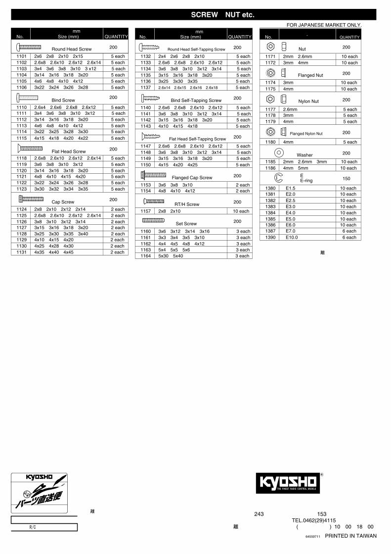
1390 E10.0 6 each
R
THE FINEST RADIO CONTROL MODELS
京商株式会社〒243 神奈川県厚木市船子153
●ユ-ザ-相談室直通TEL.0462(29)4115相談室へのお問い合わせは:月曜~金曜(祝祭日を除く) 10:00~18:00
64559711 PRINTED IN TAIWAN
1147 2.6x6・2.6x8・2.6x10・2.6x12 5 each1148 3x6・3x8・3x10・3x12・3x14 5 each1149 3x15・3x16・3x18・3x20 5 each1150 4x15・4x20・4x25 5 each
1153 3x6・3x8・3x10 2 each1154 4x8・4x10・4x12 2 each
1157 2x8・2x10 10 each
1160 3x6・3x12・3x14・3x16 3 each1161 3x3・3x4・3x5・3x10 3 each1162 4x4・4x5・4x8・4x12 3 each1163 5x4・5x5・5x6 3 each1164 5x30・5x40 3 each
1171 2mm・2.6mm 10 each1172 3mm・4mm 10 each
1174 3mm 10 each1175 4mm 10 each
1177 2.6mm 5 each1178 3mm 5 each1179 4mm 5 each
1180 4mm 5 each
サラタッピングビスFlat Head Self-Tapping Screw ●200
フランジ付キャップビスFlanged Cap Screw ●200
セットビスSet Screw ●200
フランジ付ナットFlanged Nut ●200
●200
1185 2mm・2.6mm・3mm 10 each1186 4mm・5mm 10 each
1380 E1.5 10 each
EリングE-ring ●150
サラ小丸ビスRT/H Screw ●200
ナットNut ●200
ナイロンナットNylon Nut ●200
フランジ付ナイロンナットFlanged Nylon Nut
●200ワッシャーWasher
1381 E2.0 10 each1382 E2.5 10 each1383 E3.0 10 each1384 E4.0 10 each1385 E5.0 10 each1386 E6.0 10 each1387 E7.0 6 each
● FOR JAPANESE MARKET ONLY.
※ここに明記された以外のビス、ナット等は、 『ユーザー相談室』にお問い合わせください。
1101 2x6・2x8・2x10・2x15 5 each1102 2.6x8・2.6x10・2.6x12・2.6x14 5 each1103 3x4・3x6・3x8・3x10・3 x12 5 each1104 3x14・3x16・3x18・3x20 5 each1105 4x6・4x8・4x10・4x12 5 each1106 3x22・3x24・3x26・3x28 5 each
1110 2.6x4・2.6x6・2.6x8・2.6x12 5 each1111 3x4・3x6・3x8・3x10・3x12 5 each1112 3x14・3x16・3x18・3x20 5 each1113 4x6・4x8・4x10・4x12 5 each1114 3x22・3x25・3x28・3x30 5 each1115 4x15・4x18・4x20・4x22 5 each
1118 2.6x8・2.6x10・2.6x12・2.6x14 5 each1119 3x6・3x8・3x10・3x12 5 each1120 3x14・3x16・3x18・3x20 5 each1121 4x8・4x10・4x15・4x20 5 each1122 3x22・3x24・3x26・3x28 5 each1123 3x30・3x32・3x34・3x35 5 each
1124 2x8・2x10・2x12・2x14 2 each1125 2.6x8・2.6x10・2.6x12・2.6x14 2 each1126 3x8・3x10・3x12・3x14 2 each1127 3x15・3x16・3x18・3x20 2 each1128 3x25・3x30・3x35・3x40 2 each1129 4x10・4x15・4x20 2 each1130 4x25・4x28・4x30 2 each1131 4x35・4x40・4x45 2 each
バインドビスBind Screw
●200
サラビスFlat Head Screw ●200
キャップビスCap Screw ●200
ナベビスRound Head Screw ●200
品番 サイズ(mm) 入数(各)No. Size (mm) QUANTITY
1132 2x4・2x6・2x8・2x10 5 each
ナベタッピングビスRound Head Self-Tapping Screw ●200
1133 2.6x6・2.6x8・2.6x10・2.6x12 5 each1134 3x6・3x8・3x10・3x12・3x14 5 each1135 3x15・3x16・3x18・3x20 5 each1136 3x25・3x30・3x35 5 each1137 2.6x14・2.6x15・2.6x16・2.6x18 5 each
バインドタッピングビスBind Self-Tapping Screw ●200
1140 2.6x6・2.6x8・2.6x10・2.6x12 5 each1141 3x6・3x8・3x10・3x12・3x14 5 each1142 3x15・3x16・3x18・3x20 5 each1143 4x10・4x15・4x18 5 each
品番 サイズ(mm) 入数(各)No. Size (mm) QUANTITY
品番 径 入数(各)No. ¯ QUANTITY
ビス・ナット類 SCREW・NUT etc.
京商のパーツならすぐ揃う
■パーツ入手についてパーツの入手難を解決するのが「パーツ直送便」システムです。必要なパーツがお店で品切れの時は、そのシステムを扱っている販売店に注文いただくと、京商より直接パーツが入手できます。代金はお店で、パーツは直接京商からお届けします。パーツによっては取り扱いされていない物もありますので、詳しくは左記の看板のある販売店にお問い合わせください。
メーカー指定の純正部品を使用して
安全にR/Cを楽しみましょう。


![取扱説明書 [F-08A]](https://img.pdfslide.us/doc/110x75/61cef48b0337c2187175b613/-f-08a.jpg)