Embed Size (px)
Citation preview

Telecommun Syst (2017) 66:295–309DOI 10.1007/s11235-017-0287-2
Radio communication via Near Vertical Incidence Skywavepropagation: an overview
Ben A. Witvliet1,2 · Rosa Ma Alsina-Pagès3
Published online: 21 February 2017© The Author(s) 2017. This article is published with open access at Springerlink.com
Abstract Near Vertical Incidence Skywave (NVIS) propa-gation can be used for radio communication in a large area(200km radius) without any intermediate man-made infras-tructure. It is therefore especially suited for disaster reliefcommunication, communication in developing regions andapplications where independence of local infrastructure isdesired, such as military applications. NVIS communicationuses frequencies between approximately 3 and 10MHz. Acomprehensive overview of NVIS research is given, cover-ing propagation, antennas, diversity, modulation and coding.Both the bigger picture and the important details are given,as well as the relation between them.
Keywords Radio communication · Emergency communi-cations · Radio wave propagation · Ionosphere · NVIS ·Antennas · Diversity · Modulation
B Ben A. [email protected];[email protected]
Rosa Ma Alsina-Pagè[email protected]
1 Spectrum Management Department, RadiocommunicationsAgency Netherlands, P. O. Box 450, 9700 AL Groningen, TheNetherlands
2 Telecommunication Engineering Group, University ofTwente, P. O. Box 217, 7500 AE Enschede, The Netherlands
3 GTM - Grup de Recerca en Tecnologies Mèdia, La Salle -Universitat Ramon Llull, c/Quatre Camins, 30, 08022Barcelona, Spain
1 Introduction
Recently, interest in radio communication via Near Verti-cal Incidence Skywave (NVIS) propagation has revived, notin the least because of its role in emergency communica-tions in large natural disasters that took place in the lastdecade [1–3]. The NVIS propagation mechanism enablescommunication in a large area without the need of a networkinfrastructure, satellites or repeaters. This independence oflocal infrastructure is essential for disaster relief communi-cations, when the infrastructure is destroyed by a large scalenatural disaster, or in remote regionswhere this infrastructureis lacking. In military communications, where independenceof local infrastructure is equally important, communicationsvia NVIS propagation have always remained important nextto troposcatter and satellite links.
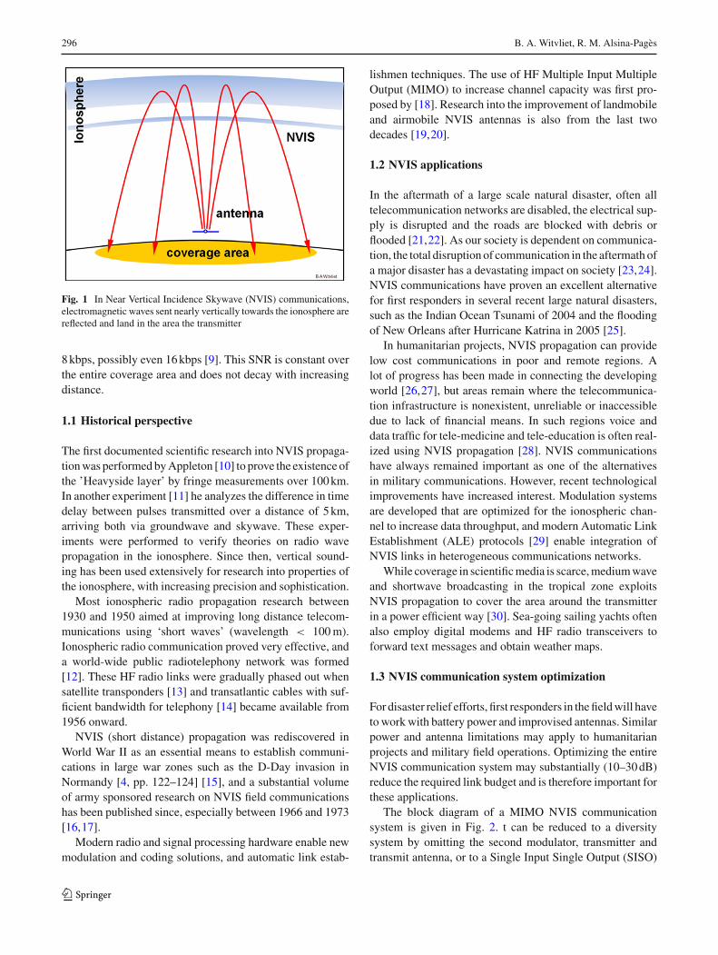
For NVIS propagation, electromagnetic waves are sentnearly vertically towards the ionosphere, the ionized upperpart of the Earth’s atmosphere. With appropriate frequencyselection, these waves are reflected back to Earth [4], asshown in Fig. 1. The great reflection height of 80–350kmresults in a large footprint and homogeneous field strengthacross that footprint. Due to the steep radiation angles largeobjects such as mountain slopes or high buildings cannotblock the radio path [5]. Typical frequencies are between 3and 10MHz. The term ’Near Vertical Incidence Skywave’was first mentioned by Rufenach et al. [6], although othersclaim that Perlman [7] named the propagation mechanism.The latter used the term ’NearlyVertical IncidenceSkywave’.
NVIS propagation may be used to cover an area with a200km radius using low power and simple antennas [4].As can be derived from the measurements in [8], a mod-est transmit power of 20W in a dipole antenna will producemore than 30dB signal-to-noise ratio (SNR) in a 3kHz band-width, which is sufficient for data transfer speeds of at least
123
296 B. A. Witvliet, R. M. Alsina-Pagès
Fig. 1 In Near Vertical Incidence Skywave (NVIS) communications,electromagnetic waves sent nearly vertically towards the ionosphere arereflected and land in the area the transmitter
8kbps, possibly even 16kbps [9]. This SNR is constant overthe entire coverage area and does not decay with increasingdistance.
1.1 Historical perspective
The first documented scientific research into NVIS propaga-tionwas performedbyAppleton [10] to prove the existence ofthe ’Heavyside layer’ by fringe measurements over 100km.In another experiment [11] he analyzes the difference in timedelay between pulses transmitted over a distance of 5km,arriving both via groundwave and skywave. These exper-iments were performed to verify theories on radio wavepropagation in the ionosphere. Since then, vertical sound-ing has been used extensively for research into properties ofthe ionosphere, with increasing precision and sophistication.
Most ionospheric radio propagation research between1930 and 1950 aimed at improving long distance telecom-munications using ‘short waves’ (wavelength < 100m).Ionospheric radio communication proved very effective, anda world-wide public radiotelephony network was formed[12]. These HF radio links were gradually phased out whensatellite transponders [13] and transatlantic cables with suf-ficient bandwidth for telephony [14] became available from1956 onward.
NVIS (short distance) propagation was rediscovered inWorld War II as an essential means to establish communi-cations in large war zones such as the D-Day invasion inNormandy [4, pp. 122–124] [15], and a substantial volumeof army sponsored research on NVIS field communicationshas been published since, especially between 1966 and 1973[16,17].
Modern radio and signal processing hardware enable newmodulation and coding solutions, and automatic link estab-
lishmen techniques. The use of HF Multiple Input MultipleOutput (MIMO) to increase channel capacity was first pro-posed by [18]. Research into the improvement of landmobileand airmobile NVIS antennas is also from the last twodecades [19,20].
1.2 NVIS applications
In the aftermath of a large scale natural disaster, often alltelecommunication networks are disabled, the electrical sup-ply is disrupted and the roads are blocked with debris orflooded [21,22]. As our society is dependent on communica-tion, the total disruption of communication in the aftermath ofa major disaster has a devastating impact on society [23,24].NVIS communications have proven an excellent alternativefor first responders in several recent large natural disasters,such as the Indian Ocean Tsunami of 2004 and the floodingof New Orleans after Hurricane Katrina in 2005 [25].
In humanitarian projects, NVIS propagation can providelow cost communications in poor and remote regions. Alot of progress has been made in connecting the developingworld [26,27], but areas remain where the telecommunica-tion infrastructure is nonexistent, unreliable or inaccessibledue to lack of financial means. In such regions voice anddata traffic for tele-medicine and tele-education is often real-ized using NVIS propagation [28]. NVIS communicationshave always remained important as one of the alternativesin military communications. However, recent technologicalimprovements have increased interest. Modulation systemsare developed that are optimized for the ionospheric chan-nel to increase data throughput, and modern Automatic LinkEstablishment (ALE) protocols [29] enable integration ofNVIS links in heterogeneous communications networks.
While coverage in scientificmedia is scarce,mediumwaveand shortwave broadcasting in the tropical zone exploitsNVIS propagation to cover the area around the transmitterin a power efficient way [30]. Sea-going sailing yachts oftenalso employ digital modems and HF radio transceivers toforward text messages and obtain weather maps.
1.3 NVIS communication system optimization
For disaster relief efforts, first responders in thefieldwill haveto workwith battery power and improvised antennas. Similarpower and antenna limitations may apply to humanitarianprojects and military field operations. Optimizing the entireNVIS communication system may substantially (10–30dB)reduce the required link budget and is therefore important forthese applications.
The block diagram of a MIMO NVIS communicationsystem is given in Fig. 2. t can be reduced to a diversitysystem by omitting the second modulator, transmitter andtransmit antenna, or to a Single Input Single Output (SISO)
123

Radio communication via Near Vertical Incidence Skywave propagation: an overview 297
Fig. 2 Block diagram of anNVIS communication system.Two propagation channels areshown, as in diversity andMultiple Input, Multiple Output(MIMO) systems. Mod. andDemod. stand for modulator anddemodulator; Tx, ’Rx and ’Ant.’stand for transmitter, receiverand antenna
system by omitting the entire second transmit–receive chain.Antenna and propagation channel together define the propa-gation channel for which the modulation and coding must beoptimized. Radio noise is present in the propagation chan-nel, but also picked op directly by the receive antenna fromits surroundings. System optimization requires research onantennaparameters, propagationmechanism, diversity, chan-nel parameters, modulation techniques and coding. Whilespecialization is needed for in-depth research in each one ofthese fields, their interaction is substantial and needs to beconsidered when studying one single aspect. For example,the chosen antenna pattern and polarization influences chan-nel fading and time dispersion, resulting in different codingand modulation optima.
1.4 Motivation of this review
Up to the 1960s most of transoceanic communications wereperformedbyHF radio systems, thanks to high altitude reflec-tions by means of the ionosphere. Considering that someof the inventions that led to that technology stem from the1930s, they must be considered an impressive innovation.Nowadays, satellites and transoceanic glass fiber cables formodern communications, which provide higher throughputsand can achieve good quality of service (QoS), have replacedHF communications. Recently there, however, there has beenrevival of the use of HF radio systems because todays tech-nology provides affordable HF radio systems, when in thepast their cost was significantly higher. Therefore, there isa renewed scientific interest in NVIS antennas, propagationand modem design following these technological advances,which also finds its way into standardization. HF radio com-munication systems and NVIS systems in particular, remainimportant for the specific applications previously depicted,where conventional communications systems cannot provideservice or have ceased operation due to unfortunate events.
Remote sensing, defense applications, emergency commu-nications when the infrastructures are down or connectingisolated places in developing countries, where modern com-munications systems cannot be deployed, are some of theapplications onwhichNVISHFcommunications are focusedtoday.
It is therefore important to have a good overview of theresearchdone in eachof thesefields.This reference collectionand organization has never been done before exhaustively;firstly, it requires coverage of all the different research areasthat NVIS comprises, and secondly the long research his-tory of this topic promises a long collection of work. Forfull coverage of the NVIS research area both recently pub-lished papers and papers from ninety years ago are equallynecessary. In addition, because of the long research historythe outcome of NVIS research is scattered over a large num-ber of scientific fora, spread over a considerable interval intime and identified with varying keywords. Consequently,to acquire an integral overview of the field alone requires aconsiderable effort and time, which would be better spent onresearch into missing aspects that connect and augment indi-vidual pieces of research. Having experienced this processin two separate NVIS research groups motivated the authorsto combine their resources and make them available to otherNVIS researchers.
This article provides an overview of research relevantto NVIS communication systems, discussing the buildingblocks and the relations between, and provides reference torelevant publications. It will help researchers to quickly buildtheir ownNVIS library. It also identifies niche subjectswithinthe NVIS research field, where additional research will con-nect and augment other research and improve the overallknowledge of NVIS propagation and related systems. It mayalso help to find NVIS research groups with complementaryresearch for cooperation.
123

298 B. A. Witvliet, R. M. Alsina-Pagès
The article is structured as follows:NVIS radiowave prop-agation is discussed in Sect. 2. Subsequently an overviewof NVIS antenna research is given in Sect. 3. NVIS chan-nel characterization and associated modulation and codingtechniques are discussed in Sects. 4 and 5. A discussionon subjects that merit more research and some concludingremarks can be found in Sect. 6.
2 Near Vertical Incidence Skywave Propagation
2.1 The ionosphere
The radiation of the sun ionizes gasses in the upper part of theEarth’s atmosphere: the ionosphere. Several ionospheric lay-ers (regions) can be identified, each layer having its particularcomposition and being ionized by specificwavelengths in thesolar radiation. In the F-layer atomic oxygen is ionized byabsorbtionof extremeUVradiation,with a peak electronden-sity at 175km height. In the E-layer, between 90 and 150kmin height, O2 absorbs soft X-ray and UV radiation. The D-layer, between approximately 60 and 90 km height, is causedby photo-ionization of NO molecules by Lyman-alpha radi-ation [32]. The D-layer, responsible for high attenuation atthe lower HF frequencies, disappears almost completely atnight. By daylight, the F-layer is split into a lower F1-layerand a higher F2-layer.
2.2 NVIS propagation
Electromagnetic waves entering the ionosphere may berefracted back to Earth, depending on the operating fre-quency. A wave traveling vertically will be reflected by oneof the layers when its operating frequency is lower than thecritical frequency of that layer. Radio waves with a frequencyabove the critical frequencywill pass through the layer at ver-tical incidence, but will be reflected at lower elevation angles[33], resulting in coverage starting at a certain distance fromthe transmitter, and a circular zone around the transmitterremaining without coverage, as shown in Fig. 3: the ‘skipzone’. To realize a coverage area around the transmitter with-out such a skip zone, the operating frequency must remainbelow the critical frequency of the layer used [32]. The prop-agation mechanism is then called Near Vertical IncidenceSkywave (NVIS). Both the E- and F2-layer can be used forNVIS links.
Absorption as well as radio noise being lower at higherfrequencies, F2-layer NVIS links will be more energy effi-cient [32]. Due to the large reflection height and relativelyshort distances covered, elevation angles are high.
Fig. 3 Transmission above the critical frequency of the ionosphereresults in a ‘skip zone’. Figure from [31]
2.3 Characteristic wave propagation
Experiments of [11] show double reflections in the F1-layer,and double reflections in the F2-layer, as we can see in Fig. 4.Appletonmathematically proved that electromagnetic wavesentering the ionosphere, under the influence of the Earthmagnetic field, are split into two circularly polarized charac-teristic waves with opposite rotation sense, the ordinary andextraordinary wave [32, p. 82]. Appleton’s magneto-ionictheory extended previous work of Maxwell and Thomson[34, pp. 404–408], who explained the polarization rota-tion found experimentally by Faraday in 1845 [35,36]. Thismagneto-ionic propagation is treated in [32,37–39]. Thecritical frequency of the ionospheric layer is different foreach of these waves. Consequently, their path through theionosphere is different, as can be shown with ray-tracingtechniques [40,41]. The waves suffer different attenuationand show different channel characteristics, such as delay andfading patterns. The polarization of the characteristic waves,as seen when entering or leaving the ionosphere, dependson the propagation of the waves with respect to the mag-netic field. In the Northern hemisphere the polarization ofthe ordinary wave is right-hand circular (IEEE definition)on the upward and left-hand circular on the downward path.The rotation sense is reversed in the Southern hemisphere.For mid-latitude locations (between 23.5◦ and 66◦ latitude)at frequencies above 5MHz, the polarization of the charac-teristic waves in NVIS propagation is nearly circular. Closerto the magnetic equator the polarization approaches linear(horizontal), at the magnetic poles it is circular [32, pp. 77–83].
2.4 Diurnal variation and solar cycle
The solar energy absorbed in the ionosphere changes withthe slant of the incoming sun rays, and the ionization of theionosphere shows a diurnal variation [42]. The critical fre-
123

Radio communication via Near Vertical Incidence Skywave propagation: an overview 299
Fig. 4 NVIS measurements by Appleton and Builder. Upper trace pulses are received first via ground wave (G), then twice via the F1-layer (F1′and F1′′) and twice via the F2-layer (F2′ and F2′′). Lower trace a 1115Hz sine wave serving as time reference. Graph adapted from [11]
quency follows this pattern with a maximum near mid-dayand a minimum in the early morning, just before sunrise. Forthe same reason, at mid-latitudes, the ionization follows theseasons. On top of that, the radiation of the Sun varies overtime following its sidereal rotation and its 11-year sunspotcycle [32, p. 36]. TomaintainNVIS propagation, a frequencyhas to be selected that remains below the critical frequencyof the F2 layer for a larger part of the day, and a lower fre-quency must be used at night. However, both Walden [43]and Witvliet et al. [44] report above-the-MUF propagationat night. The latter show that the daytime characteristic wavepropagation disappears at night, to be replaced by scatteringwith significantly lower efficiency. Research on NVIS linkperformance can be found in [45] for high latitudes, and in[46] for the specific case of low solar flux indices.
2.5 Propagation prediction
To gain insight in the present NVIS propagation, measure-ments from the nearest ionosonde may be used. Observingthe diurnal variation of the critical frequency of the F2-layerfor the ordinary wave (foF2) and extraordinary wave (fxF2or fxI) over one or two sidereal days will give an indicationof the propagation to be expected in the next few days. John-son [47] compares measured 24hNVIS link availability withVOACAP [48] simulations on several frequencies between 3and 9MHz during a solar minimum.Walden [49] reports thatseveral propagation prediction models neglect the effect ofthe extraordinary wave. In [50] basic recommendations andformula for ionospheric propagation prediction are provided,and in [51] a state-of-the-art ionospheric prediction model isdescribed. Combination of ionospheric parameters measuredin real time with ray-tracing software using the InternationalReference Ionosphere (IRI) model [52,53] makes improvedshort-term propagation predictions possible.
3 NVIS antennas
As the ITU Handbook on Emergency Telecommunications[54] states: “Time, effort and money invested in the antennasystem will generally provide more improvement to com-munications than an equal investment to any other part
of the station”. Realizing this, several investigators pub-lished results on NVIS antenna optimization. Importantparameters for NVIS antenna optimization are antenna dia-gram, polarization and bandwidth. As only high elevationangles contribute to NVIS propagation [55], optimizing theantenna diagram for these elevation angles will increasethe effectively transmitted power and improve the signal-to-interference ratio at reception.
This section is organized in sections on fixed, field expedi-ent, mobile and receive antennas, each application imposingspecific limitations to the antenna optimization. A sectionon in-situ NVIS antenna measurement is added. The sectionconcludes with the influence of the antenna characteristicson channel parameters.
3.1 NVIS antennas for fixed installations
With some variation between different sources [4,56] prac-tical NVIS operating frequencies range from approximately3–10MHz, corresponding with wavelengths of 30–100m.Therefore, if this entire frequency range is to be coveredwith high directivity and high efficiency, the antenna willbe large. In fixed installations this is acceptable: the effortin mechanical engineering is balanced by a large reductionin required transmitter power, as well as an improvementimmunity to interference and radio noise on reception.NVIS antennas suitable for fixed installations are the Deltaantenna [57], the vertical Rhombic antenna [58, pp. 11.7–11.16], and the Log-Periodic Conical Spiral antenna [59].These antennas are often used in ionosonde installationsbecause of their frequency independent behavior. The Con-ical Spiral antenna provides circular polarization with high(30dB) cross-polarization [59], its polarization sense beingdetermined by the winding direction. In fixed military instal-lations a vertically oriented Log-Periodic Dipole Antenna(LPDA) is also used [4, p. 48]. A derivative, the Log-PeriodZig-Zag antenna, is described in [60]. Broadside arrays ofmultiple dipole antennas [61] may also be considered, buttheir frequency coverage is generally limited to one octave.The Conical Spiral antenna and the vertically Log-PeriodicDipole Antenna can be seen in Fig. 5a, b.
123

300 B. A. Witvliet, R. M. Alsina-Pagès
Fig. 5 NVIS antennas for fixed, portable and mobile use: a Vertical Log-Periodic Dipole Antenna (LPDA). b Conical Spiral Antenna. c TurnstileAntenna. d Mobile Car Loop Antenna. Figures taken from [4,8,59] and [19]
3.2 Field expedient NVIS antennas
For field expedient use, the antennas described above arenot practical: their transportation is cumbersome and theirinstallation time-consuming, in some terrain even impossi-ble. However, simple and light wire antennas can providegood NVIS performance, alongside with the desired flex-ibility. E.g. a simple wire dipole antenna may exhibit anantenna gain of approximately 6dBi at high angles, groundreflection included [62], and such an antenna may be strungin-between trees or suspended in an ‘inverted vee’ fashionfrom lightweight extendable fiberglass or aluminum masts.
Extensive simulations and in-situ antenna pattern measure-ments on simple wire dipoles, Inverted L [4, p. 50] andend-fed slanted wire antennas have been performed in [62].This research included the influence of vegetation, antennaheight and the Earth’s magnetic field in California, USA andin Thailand.
3.3 NVIS antennas for mobile use
The size limitations of antennas for moving vehicles intro-duce specific problems concerning radiation diagram andefficiency. Vertical whip antennas on vehicles perform badly
123

Radio communication via Near Vertical Incidence Skywave propagation: an overview 301
in NVIS, as their radiation pattern shows a pronounced min-imum at high elevation angles. Measured antenna gain atthese angles range from −35dBi at 4MHz to −10dBi at8MHz [63]. Tilting the whip over the vehicle will onlydecrease the performance [19], and tilting the whip awayfrom the vehicle is generally not possible when on the move.In [5] a car-mounted vertical half loop antenna is described,using capacitance loading to achieve an NVIS antenna gainbetween −12 and −10dBi from 3 to 8MHz. This antennais depicted in Fig. 5d. Similar NVIS loop antennas may bedesigned for transport aircraft [20], helicopter [64] and ships.Due to its increased size, the shipboard loop in [65] achievesan NVIS antenna gain between −1 and +4dBi between 2and 7MHz. In helicopters, the antenna designer has to pre-vent unwantedmodulation of the signal by the rotating rotors[64,66].
3.4 Antennas for NVIS reception
Most of the publications presume that the same antenna isused for both transmission and reception. This is not neces-sarily the best solution. For reception the average directivityover the NVIS elevation angles is more important than theantenna gain [67, pp. 766–767] [31, pp. 137–143]. As HFreception is limited by the ambient electromagnetic noise orradio noise [68] rather than by the receiver sensitivity, abso-lute gain is less important than discrimination between thewanted signal on one hand, and radio noise and interferenceon the other. Discrimination of the receive antenna diagrambetween the NVIS elevation angles and angles at which mostinterference and ambient noise arrives [69] will significantlyimprove reception. While unsuitable for transmission, com-pact active antenna elements may provide maximum (i.e.ambient noise limited) sensitivity [70]. Directive arrays maybe composed of several such active antenna elements andspatial filtering can be used to further improve the signal-to-noise ratio on reception [71].
3.5 NVIS antenna pattern optimization
For the optimization of NVIS antennas, often only theantenna gain at zenith angles is considered. However, onthe desired coverage area size and the ionospheric reflectionheight, the average directivity in a range of spatial anglesmust be considered [31, p. 137]. For that purpose, graphsrelating elevation angle to great circle distance are providedin [32,72] and their dependency on the operating frequencyand the sunspot number is shown in [31, pp. 132–135].
3.6 In-situ NVIS antenna measurement
Due to their size, NVIS antennas cannot be measured inanechoic rooms. This is also true for the (smaller) mobile
antennas, as their supporting platform is an integral part of theradiating structure. Also the influence of the ground under-neath the antenna installation is not negligible and has tobe included in the measurement. However, in-situ measure-ment of antenna pattern and relative gain can be used forantenna evaluation, using a small transmitter transported byhelicopter [73], airplane [74], tethered balloon [5] or remotecontrolled octocopter drone [75]. Due to the fast and deepfading imposed by ionospheric propagation, comparison ofantenna performance using real-live NVIS transmitters isonly possible when specialized techniques are used, suchas described in [31, pp. 139–140]. In [17] an ionosonde isused to compare the antenna gain of two antennas at zenithangle using pulsed measurements.
4 NVIS channel characteristics
In this section NVIS channel sounding and modelling isdiscussed, including their variation with latitude. Severalexperiments have been conducted by Burgess and Evans [76]and Tooby et al. [77,78] to characterize the NVIS channel inthe United Kingdom. Their results can be used to simulatethe influence of the channel, enabling performance testingof modulation and coding systems without on-air measure-ments [79]. Channel simulations also enable comparison ofmodulation and coding systems in identical circumstances,which is not possible with real propagation.
4.1 NVIS channel sounding
In order to design the modulation and coding system thatminimises the Bit Error Rate (BER) and maximizes thethroughput of an ionospheric link, a sounding system cover-ing the entire HF band was designed in [80] and improvedin [81], in this case for a long distance link. Real data froma Lowell ionosonde [82] has been used by Hervas et al. [56]to characterize the NVIS channel. This data can be used totrade-off BER and bit rate when designing modulation andcoding techniques for an HF NVIS channel. Other researchuses Digital Radio Mondiale (DRM) broadcast signals [83]and radio noise measurements to calculate the parameterswith which the best channel availability is obtained [84,85].The latter discusses medium-wave NVIS propagation, whichhas different characteristics than HF NVIS propagation. Pre-vious research of Tooby [77] used a chirp sounder tomeasurethe signal-to-noise ratio (SNR) and multipath characteristicsbetween 1998 and 1999.
4.1.1 Fading
Ionospheric propagation is prone to signal fading. Figure 6shows slow fading caused by changing ionospheric reflec-
123

302 B. A. Witvliet, R. M. Alsina-Pagès
Fig. 6 NVIS measurements,showing fast deep multipathfading superimposed on slowerflat fading. Figure taken from[8]
tivity and absorption on a timescale of tens of minutes, withsuperimposed fast (seconds) anddeep (down to−30dB)mul-tipath fading, caused by interference between signals arrivingvia ionospheric paths of different length [86]. For the designof communication systems, knowledge of the mean value ofthe received signal is insufficient: signal fading has a pro-nounced effect on the data reception. An extra signal marginhas to be reserved for the fadingminima, the ‘fadingmargin’,and the coding has to be adapted to allow for temporary sym-bol loss. McNicol [87] discusses fading on vertical incidencesignals between 2 and 6MHz.
Fading time series are usually studied and modeled usingstochastic processes [88,89]. It is assumed that the fadinggenerated by the composition of multiple ionospheric echoescan be represented as the sum of the specularly reflectedsignals plus a random component; this is modelled by theNakagami-Rice distribution [90]. If the random componentdominates, this probability function approaches a Rayleighdistribution [91]. According to Davies [32, p. 237], shortobservations of ionospheric fading on long-distancxe linkswill reveal Rayleigh fading, while longer observations willshow a log-normal signal distribution. Burgess [76] showsthat NVIS propagation conditions may exist also in whichfading is almost completely absent.
4.1.2 Doppler spread
Not only the depth of the fading is important, but also itsperiodicity. Fading rates are often expressed in terms of theautocorrelation of the times series. This autocorrelationmea-sures the time difference by which a point in the time seriesis decoupled from its neighbors. This time difference mea-sured by autocorrelation is usually called ‘coherence time’[92]. The coherence time has a direct relationship with the
Doppler spread of the channel [92]. Channels with largeDoppler spread have signal components that change in phaseover time, since the fading depends on whether the additionof components is constructive or destructive; these channelshave a short coherence time. The coherence time has to betaken into account when choosing the symbol time of themodulation, to assure that the channel has an approximatelyconstant response during the symbol.
4.1.3 Delay spread
The delay spread is a measure of the amount of multipathpropagation in a communications channel [92]. In general,it is interpreted as the difference between the time of arrivalof the earliest significant multipath component and the timeof arrival of the latest significant multipath component. It isusually obtained by measuring the power delay profile of thechannel [93]. Figure 7 shows both Doppler and Delay Spreadof a high latitude path in Scandinavia [94]. The delay spreadmay cause Inter Symbol Interference (ISI). When design-ing a modulation system, the symbol duration must be longenough—usually 10 times the delay spread—so that an ISI-free channel is obtained [95].Delay spread in the timedomainis linked to ‘coherence bandwidth’ in the frequency domain,which is the is a statistical measure of the range of frequen-cies over which the channel passes all spectral componentswith approximately equal gain and linear phase [95].
4.2 NVIS channel modelling
For many years, the model of Watterson et al. [96], alsodescribed in ITU-R Rec. F.1487 [97], has been the standardionospheric channel model for analysis and performanceevaluation of HF communication systems. While this model
123

Radio communication via Near Vertical Incidence Skywave propagation: an overview 303
Fig. 7 Doppler and delay spread on a high latitude path in Scandinavia, measured with Doppler And Multipath SOunding Network (DAMSON).Figure adapted from [94], a measurement on a 180km NVIS link between Harstad (Norway) and Kiruna (Sweden)
properly simulates the signal perturbations such as signal fad-ing, Doppler and delay spread occurring in an interval of afew seconds, it does not represent the variations of the chan-nel quality, especially the SNR, occurring in longer intervalsin the range of a few seconds to 10min. In [98], both long-haul and NVIS measurements are performed to model theSNR variations to improve theWatterson model. Some workcan be found on the study and modelling of the channel char-acteristics using polarization diversity techniques to improvesystem performance [56]. Finally, measurements on broad-cast signals in the medium wave (MW) band are used toimprove the accuracy of the channel predictions for networkplanning in that band [84,99], providing the first channelmodel for NVIS in the medium wave band [100]; a tapdelayed line (TDL) model based upon the field measure-ments.
4.3 NVIS channel characteristics as function of thelatitude
In several propagation reference books [32,38,101] detailedexplanations about the physical phenomena in the iono-sphere are presented. In terms of HF communications, theionosphere study is divided into three zones: (i) polar zone(latitudes greater than 66◦), (ii) mid latitudes (between 23.5◦and 66◦) and (iii) equatorial zone (between 23.5◦N and23.5◦S) [102], each of them with its own particularities.
Wagner and Goldstein [45] are among the first to charac-terize the performance of the high-latitude ionospheric NVISchannel. Warrington et al. [103] and Jodalen et al. [104],amongst others, also provide a thorough channel analysisfor high latitudes NVIS paths. Jodalen et al. [104] presentsthe results from a propagation experiment over two NVISpaths in Northern Scandinavia using Doppler and MultipathSOunding Network (DAMSON) [105], with the aim of cor-relating the results of both paths. Warrington et al. [103]presents directionfindingmeasurements inNorway andSwe-
den, to better understand the directional characteristics of HFsignals reflected in the high-latitude ionosphere. Lossman etal. [106], who performed tests in the Baltic region, concludedthat transmit frequencies greater than 5MHz show highereffective data speeds due to the fact that man-made noise ismostly concentrated between 2 and 5MHz.
In [77], the quality of mid-latitude NVIS channels is mea-sured, evaluating SNR and multipath data. Hervas et al. [56]performsmid-latitudeNVIS channel soundings using a Low-ell Digisonde [82], obtaining information about Doppler andmultipath delay spread, and the best possible transmissionfrequency as function of the hour of the day. Austin [15]describes the performance of the equatorial ionosphere, andfinally, in [105] channel soundingwith theDAMSON systemwas used to evaluate polar, mid-latitude and equatorial prop-agation channels for the use of 12kHz wide HF broadcastsystems operating on fixed frequencies and requiring highavailability.
5 Modulation and coding for the NVIS channel
This section consists of two blocks. The first focuses onmapping different data transmission methods for NVIS tech-nology and enumerating several physical layer proposalsresponding to the needs of each of the communication situa-tions. The second block gives light on the use of diversity andMIMO techniques to improve data transmission throughputusing time, space, and frequency or polarization diversity.
The aim of this section is to give the reader an idea ofthe map of previous scientific work performed related toNVIS modulation and coding. It not meant to be an exhaus-tive comparison between the different modulations or codes,since they are too different from each other to be comparedone by one; the intention is not to conclude that there is onebetter than the others are, since each responds to their circum-stances. The reader will be able to find references that are of
123

304 B. A. Witvliet, R. M. Alsina-Pagès
interest reading a brief description of each; also a compara-tive table of the basic parameters in terms of SNR, bandwidthand throughput is presented at the end of the section, gather-ing most of the proposals.
5.1 Data transmission methods for NVIS
In the bibliography, several different physical layer designscan be found that are adapted to the parameters that arespecific to HF propagation. There are no special recommen-dations for NVIS links, all the HF recommendations andstandards cover both long-haul and short distance communi-cation.
5.1.1 ITU recommendations
Several ITU recommendations contain information on fadingand its impact on modulation [86], delay spread evaluation[93] and modem test [97]. These documents are developedby theRadiocommunicationSector, and are informative only,but give the first keys of the implementation to the designer.
5.1.2 Military HF data transmission protocols
Some of the HF Data Transmission Protocols (e.g. STANAG4415, MIL-STD 118 110C and DRM) are designed to workfor both NVIS and oblique incidence propagation, and areoptimized for data transfer in the presence of fading, multi-path and noise. In [107], the link availability of two modems(one compatible with STANAG 4415 and 4285, and the sec-ond only with STANAG 4285) is compared with Morse codeand voice traffic. Davies [108] contains measurements ofthroughput in relation to SNR for STANAG 4539 [109] overseveral distances, to evaluate the effects of low SNR andvariable channel conditions, taking into account advancedwaveforms, coding and protocols.
In [110] two alternative channel access technologies aretested and compared in wireless mesh networks: AutomaticLink Establishment (ALE) and fixed-frequency MAC proto-cols. These are also described in the book of Johnson et al.[111]. In [112] we find measurements on a MIL-STD-188-110C [113] link over distances of up to 160km, providingthe users with bit rates up to 9.6kbps in 6–9kHz RF band-width. The standard gives the option of selecting bandwidthand modulation, and includes wideband modulation with upto 24kHz bandwidth with elaborate coding and interleaving.
5.1.3 HF broadcasting protocols
Digital Radio Mondial (DRM), an international radio broad-casting standard launched in 2003, solves fading and phasedistortion problems associated with shortwave AM broad-casting and offers both increased audio quality and band-
width [85]. Spreading the information in frequency and timeover multiple carriers using OFDM modulation makes thesystem less prone to selective fading. Coding and interleav-ing are implemented and their parameters can be selectedto match the expected propagation channel. An option forNVIS is included. In the thesis of Losada [85] a study of theapplication of DRM is detailed, evaluating the statistical per-formance of the modem in different environments (Dopplerspread, delay spread, interference), but it must be noted thatthe empirical results come from medium-wave NVIS exper-iments.
5.1.4 Commercial radio protocols
Commercial HF radio modem protocols such as PacTor IVclaim to achieve 5.5kbps in 2.4kHz RF bandwidth at 17dBSNR and to maintain the link down to −21dB SNR [114].PacTor has proven successful in disaster relief communica-tion and is used for radio mail and weather map transferfor sea sailing yachts. A scientific comparison with otherprotocols is provided by ITU-R Recommendation F.339[115,116].
5.1.5 Experimental physical layer definitions
Hoult et al. [9] present a study to achieve 16kbps in a standard3kHz wide HF channel, to improve on the 2.4 or 4.8kbpsmodems that were available at the time. It uses an NVISchannel instead of a VHF link, which could not be used dueto the accidented terrain. Several other studies were doneto improve the effective bitrate of modems used in one-hopionospheric propagation and NVIS propagation [107]. John-son [110] details modem characteristics for a wireless meshnetwork for NVIS propagation, long-haul skywave and sur-face wave signals.
In [117] there is a study of several modulation techniquestested over a distance of 160km on frequencies between2.8MHz and 9.4MHz, presenting measured SER (SymbolError Rate) values for data rates from 4.3 to 20.6kbps.More details of this work can be found in Christofi’s the-sis [118]. Finally, [119] presents over the air transmissionsresults obtainedwith amulti-narrow bandHFmodemoperat-ing over non-contiguous 3kHz bands spread over a 200kHzwide subband.
5.2 Diversity and MIMO
Reducing fading and increasing throughput on anHF channelcan also be realized using diversity techniques. Frequencydiversity, time diversity, antenna (spatial and polarization)diversity and adaptive beamforming to suppress unwantedmultipath were originally invented in the early 1930s, andimplemented in intercontinental HF radio communication
123

Radio communication via Near Vertical Incidence Skywave propagation: an overview 305
Table 1 An overview of the net throughput, bandwidth and SNR in a fading channel of several transmission systems
Protocol Modulation Net datarate SNR (dB) BW (kHz) SNR (3kHz) [dB] Source
PacTor IV (speed 1) 2 tone chirp 47 bps −22 2.4 −23 [114]*
MIL-STD-188-110A 8-PSK 75 bps 3 3 3 [116]
Pactor II (speed 4) 2-tone DPSK 150 bps 8 0.5 0 [116]
Pactor II (speed 6) 2-tone DPSK 300 bps 28 0.5 20 [116]
MIL-STD-188-110A 2-tone 8-PSK 2.4kbps 18 3 18 [116]
MIL-STD-188-110B QPSK 3.2kbps 15 3 15 [116]
PacTor IV (speed 10) 18-tone 32-QAM 5.5kbps 14 2.4 13 [114]*
Experimental 56-tone 256-QAM 8kbps 23 3 23 [9]
MIL-STD-188-110B 64-QAM 9.6kbps 33 6 36 [116]
Experimental 256-QAM 16kbps 35 3 35 [9]
Experimental 16-QAM MIMO 60kbps 19 25 28 [122]
MIL-STD-188-110C 256-QAM 64kbps 20 24 29 [112]
As measurement methods are not always described in full and differ from one researcher to the other, these values must be taken as indicative. Theitems with * are unverified manufacturer specifications only
systems [120,121]. At the technological level of that era thisrequired great ingenuity and considerable expenses. Today’sRF and signal processing hardware allows compact andcheap realization of elaborate diversity systems, promisingsubstantial reductions in required link budget. Diversity sys-temmay be integrated in the coding software on both ends ofthe link (MIMO), in selection software after the demodulator(selection diversity), or in the baseband of the receiver (e.g.optimum ratio combining). Enserink [122] proposes aMIMOsolution doubling the net data throughput from 30 to 60kbpsin a 25kHz channel. Using modern means to generate andreceive dual circular polarization [123], characteristic wavepropagation may be used to provide increased diversity gain[124,125]. NVIS characteristic wave MIMO systems havebeen proposed by Ndao et al. [126].
An overview of the net throughput, bandwidth and SNR ina fading channel of several transmission systems is given inTable 1 for comparison. To compare the necessary receivedsignal strength for systems with a different bandwidth, theSNRhas been calculated in an equivalent bandwidth of 3kHzalso. As measurement methods are not always described infull and differ from one researcher to the other, these valuesmust be taken as indicative.
6 Discussion and conclusions
A large amount of research has already been done on individ-ual components of the NVIS radio communication system,but several subjects remain that merit investigation, to aug-ment or interconnect the existing research. In this section, wehave identified the niche subjects that merit future investiga-tion. Both research in antennas and propagation as well as inmodulations and channel coding will lead NVIS research to
the next stage of evolution using todays technology, the firstdue to the polarization diversity study, which will increasethe benefits of the ionospheric channel propagation, and thesecond one to improve the throughput and the quality of ser-vice of the communications. References to recent work onthe topic are added to record the research niches that arebeing developed by different research groups that presentlyperform research in those fields.
6.1 Antennas and propagation
Empirical research into the nature of polarization fading,together with measures to reduce this fading. Documentedobservations of the presence of multipath fading in a singlehop single layer NVIS propagation path—with polarizationfading excluded—would trigger new research on the natureof fading mechanisms within a single layer.
Using the definitions of NVIS antenna gain and NVISdirectivity given in [31], comparison of a large number ofNVIS antenna types, preferably for several coverage areasizes, and accompanied by their optimum dimensions andoptimum installation heights would be a valuable asset asreference material for NVIS antenna selection. Verificationof theoretical and simulated antenna optimizations under liveNVIS propagation conditions are desirable to validate theseoptimizations.
Experiments with antennas with polarization matchedto the characteristic waves in the ionosphere could bringnew insights and applications. Compact antennas to produceadapted or adaptive polarization would be an asset for suchexperiments. Research into arrays of small active antennaelements providing maximum NVIS directivity or spatialfiltering could significantly contribute to enhanced NVISreception in areas where man-made noise is dominant.
123
306 B. A. Witvliet, R. M. Alsina-Pagès
Several research groups are already working on thosefuture trends in NVIS propagation and antenna design nowa-days. In [43], Walden describes the findings associated withan experiment conducted at 5MHz in the United Kingdomand studies the high frequency Near Vertical Incidence Sky-wave Propagation; while in [44] Witvliet et al. study deeplythe impact of a Solar X-Flare on NVIS characteristic wavepropagation, giving details of the daytime characteristicwaverefraction and of the nighttime scattering. Both authors reporton nighttime above-the-MUF propagation. Finally in [127],Ignatenko et al. detail a wide-bandmobile HF antenna designfor NVIS applications.
6.2 Channel modulation and coding
Channel simulators for F2-layer and E-layer NVIS linksfor several bandwidths are helpful to compare and improvemodulation and coding protocols. These models shouldincorporate selectable and combined ordinary and extraordi-nary wave channels for the design of diversity and MIMOsystems. Comparison of a large number of standardizedHF communication protocols over identical NVIS channelswould allow comparison and analysis of the effectivenessof different solutions in modulation, coding, and adaptivebehavior and the efficiency of their spectrum use. Open (non-proprietary) modulation, coding and data transfer protocolsare needed, to encourage further development by third par-ties. Protocols designed to achieve consistent high data ratesin the complex NVIS channels are much sought after, buthigh data rates are not always priority. Research into lowspeed protocols achieving highly reliable data transfer withacknowledgment at very low SNR are invaluable to transferlifesaving information when circumstances (antenna situa-tion, battery power, propagation) are unfavorable. Diversityand MIMO systems may increase data throughput at lowSNR values. Research into efficient solutions for conver-sion and digital transmission of narrowband (300 Hz–3kHz)voice would encourage the replacement of present low-costapplications using analog modulation. In this direction, lowcost flexible all-digital hardware platforms are needed for theimplementation and testing of open modulations and codes,and for ad-hoc designs for specific applications [128].
6.3 Interaction of building blocks
Research into the interaction of building blocks such asantenna, propagation, modulation system and coding, mayprevent that isolated optimization of single blocks leads to asuboptimal overall design.
6.4 Conclusions
An overview is given of the main building blocks of anNVIS radio communication system and specialized researchinto each of these building blocks. References are providedto a large cross section of the existing literature on NVISradio communication systems, to provide new researchers inthis field with an initial NVIS library, without pretending tobe exhaustive. Investigators are encouraged to contribute toNVIS research, especially in the areas indicated in the pre-vious Section, to contribute to increased reliability of NVISemergency communication systems.
Acknowledgements Rosa Ma Alsina-Pagès would like to thank theSecretaria d’Universitats i Recerca del Departament d’Economia iConeixement (Generalitat de Catalunya) under Grant ref. 2014-SGR-0590.
Open Access This article is distributed under the terms of the CreativeCommons Attribution 4.0 International License (http://creativecommons.org/licenses/by/4.0/), which permits unrestricted use, distribution,and reproduction in any medium, provided you give appropriate creditto the original author(s) and the source, provide a link to the CreativeCommons license, and indicate if changes were made.
References
1. Straw,R.D. (2005).What’s the deal aboutNVIS?QST, 12, 38–43.2. Lindquist, R. (2005). The Katrina Chronicles. QST, 11, 43–48.3. Ewald, S.,&Lindquist, R. (2006). TheKatrinaChronicles 2.QST,
2, 50–53.4. Fiedler,D.M.,&Farmer, E. J. (1996).Near vertical incidence sky-
wave communication: Theory techniques and validation. Sacra-mento: Worldradio Books.
5. Austin, B. A., & Murray, K. P. (1988). The application ofcharacteristic-mode techniques to vehicle-mounted NVIS anten-nas. IEEE Antennas and Propagation Magazine, 40(1), 7–30.
6. Rufenach, C. L., & Hagn, G. H. (1966). Comparison of C-2 iono-spheric sounder data with frequency predictions for short-rangecommunication with man-pack transceivers in Thailand, Spec.Techn. Rep. 15, Stanford Research Institute, Menlo Park, CA,USA.
7. Perlman, S. (1970).High frequency SAFOC digital data link tests,R & D Techn. Rep. ECOM-3341, ECOM US Army ElectronicsCommand, Ft. Monmouth, NJ, USA.
8. Witvliet, B. A., Van Maanen, E., Petersen, G. J., Westenberg, A.J., Bentum, M. J., Slump, C. H., et al. (2015). Measuring theisolation of the circularly polarized characteristic waves in NVISpropagation. IEEE Antennas and Propagation Magazine, 57(3),120–130.
9. Hoult, N. S., Whiffen, J. R., Tooby, M. H., & Arthur, P. C. (2000).16 kbps Modems for the HF NVIS Channel. In Presented atHFRST (pp. 317–321) .
10. Appleton, E. V., & Bartlett, M. A. F. (1925). On some directevidence for downward atmospheric reflection of electric rays.Proceedings of the Royal Society of London, 109(752), 621–641.
11. Appleton, E.V.,&Builder,G. (1933). The ionosphere as a doubly-refracting medium. Proceedings of the Physical Society, 45(2),208–220.
12. Heising, R. A. (1940). Radio extension links to the telephonesystem. Bell System Technical Journal, 19(4), 611–646.
123

Radio communication via Near Vertical Incidence Skywave propagation: an overview 307
13. Maunsell, H. I., & Stafford, J. W. (1964). Telstar design and con-struction and early results of the scientific space experiments.IEEE Transactions on Communication and Electronics, 83(70),27–37.
14. Mervin, K. J., Radley, G., Gilman, G. W., & Halsey, R. J. (1955).A transatlantic telephone cable. Bell System Technical Journal,102(2), 117–130.
15. Austin, B. A. (2000). Near vertical incidence skywaves in worldwar II: An historical perspective, HF Radio Systems and Tech-niques. Guidford.
16. Ray, W. A., Barker, G. E., & Martensen, S. S. (1966). Full-scalepattern measurements of simple HF field antennas in a US coniferforest. Spec. Tech. Rep. 25, Stanford Research Inst., Menlo Park,CA, USA.
17. Hagn, G. H. (1973). On the relative response and absolute gaintoward the zenith of HF field-expedient antennas: Measured withan ionospheric sounder. IEEE Transactions on Antennas andPropagation, 21(4), 571–574.
18. Strangeways, H. J. (2006). Estimation of signal correlation atspaced antennas for multimoded ionospherically reflected signalsand its effect on the capacity of SIMO and MIMO HF links. InPresented at IRST, London, UK (pp. 306–310).
19. Austin, B. A., & Liu, W. C. (2002). Assessment of vehiclemounted antennas for NVIS applications. IEE Proceedings-Microwaves, Antennas and Propagation, 149(3), 147–152.
20. Cummings, N. P. (2005). Design and analysis of a patternselectable airborne HF antenna. In Presented at ACES (pp. 499–502). Hawaii: Honololu.
21. Kwasinski, A., Weaver, W. W., Chapman, P. L., & Krein, P.T. (2006). Telecommunications power plant damage assessmentcaused by Hurricane Katrina—Site survey and follow-up results.In: Presented at INTELEC. Providence, RI, USA.
22. Mikami, T., Shibayama, T., & Esteban, S. (2012). Field sur-vey of the 2011 Tohuku earthquake and Tsunami in Miyagiand Fukushima Prefectures. Coastal Engineering Journal, 54(1),117–130.
23. Bodson, D. (1992). When the lines go down. IEEE Spectrum,29(3), 40–44.
24. Sims, B. (2007). The day after the Hurricane: Infrastructure order,and the New Orleans Police Department’s Response to HurricaneKatrina. Social Studies of Science, 37(1), 111–118.
25. Comfort, L. K. (2006). Cities at rtisk: Hurricane Katrina and theDrowningofNewOrleans.UrbanAffairsReview,41(4), 501–516.
26. Maitland, D. (1984). The missing link. International Telecommu-nication Union, Geneva: Report of the International Commissionfor World-Wide Telecommunications Development.
27. Ayeni, V., &Milward-Oliver, G. (2005).Maitland+20: Fixing themissing link. Bradford on Avon: Anima Centre.
28. Linden, L. F. (2004). Winlink 2000 in the Jungle.QST, 11, 42–45.29. Le Masson, J., Erhel, Y. M., & Mamane, A. R. (2012). Simulated
performance of the STANAG 4538 HF transmission standard. InPresented at IRST, UK: York.
30. Adorian, P., & Dickinson, A. H. (1952). High frequency broad-cast transmission with vertical radiation. Journal of the BritishInstitution of Radio Engineers, 12(2), 111–116.
31. Witvliet, B. A., Van Maanen, E., Petersen, G. J., Westenberg,A. J., Bentum, M. J., Slump, C. H., et al. (2015a). Near verticalincidence skywave propagation: Elevation angles and optimumantenna height for horizontal dipole antennas. IEEE Antennasand Propagation Magazine, 57(1), 1–18.
32. Davies, K. (1990). Ionospheric radio. Exeter: Peter Peregrinus.33. Martyn, D. F., Cherry, R.O.,&Green, A. L. (1935). Long distance
observations of radio waves of medium frequencies. Proceedingsof the Physical Society, 47(2), 340–351.
34. Maxwell, J. C. (1873). A treatise on electricity and magnetism,part II. Oxford: Clarendon Press.
35. Faraday, M. (1845). On the magnetization of light and the illumi-nation of magnetic lines of force. Philosophical Transactions, 1,1–30.
36. Knudsen, O. (1976). The Faraday Effect and Physical Theory1845–1873.Archive for History of Exact Sciences, 5(3), 235–281.
37. Ratcliffe, J. A. (1962). The magneo-ionic theory and its applica-tion to the ionosphere. London: Cambridge University Press.
38. Budden, K. G. (1985). The propagation of radio waves. London:Cambridge University Press.
39. Rawer,K. (1993).Wavepropagation in the ionosphere.Dordrecht:Kluwer Academic.
40. Reilly, M. H. (1991). Upgrades for the efficient three-dimensionalionospheric ray tracing: Investigation of HF near vertical inci-dence sky wave effects. Radio Science, 26(4), 971–980.
41. Reilly, M. H. (2000). Ray trace calculation of ionospheric propa-gation at lower frequencies. Radio Science, 41(5), 1–6.
42. Chapman, S. (1939). The atmospheric height distribution of band-absorbed solar radiation. Proceedings of the Physical Society,51(1), 93–109.
43. Walden, M. C. (2016). High-frequency near vertical incidenceskywave propagation. IEEE Antennas and Propagation, 58(6),16–28.
44. Witvliet, B. A., vanMaanen, E., Petersen, G. J., &Westenberg, A.J. (2016). Impact of a solar X-flare on NVIS propagation. IEEEAntennas and Propagation Magazine, 58(6), 29–37.
45. Wagner, L. S., & Goldstein, J. A. (1995). Channel spread param-eters for the high-latitude, near-vertical-incidence-skywave HFchannel: Correlation with geomagnetic activity, NRL/FR/5550-95-9772. Washington: Naval Research Lab.
46. Farmer, E. J. (1996). NVIS propagation at low solar flux indices.In D. M. Fiedler & E. J. Farmer (Eds.), Near vertical incidenceskywave communication: Theory, techniques and validation.Sacramento: Worldradio Books.
47. Johnson, E. E. (2007). NVIS communications during the solarminimum. In Presented at MILCOM, Orlando, Fla.
48. Perkiomaki, J. (2003–2014).HFpropagationpredictionand iono-spheric communications analysis. www.voacap.com.
49. Walden, M. C. (2009). The extraordinary wave mode: Neglectedin current practical literature on HF NVIS communications. InPresented at IRST, Edinburgh.
50. ITU. (1995). Reference ionospheric characteristics and methodsof basic MUF, operational MUF and ray-path prediction. ITU-RRec. P.434-6, International Telecommunications Union, Geneva,Switzerland.
51. Zolesi, B., & Cander, L. R. (2014). Ionospheric prediction andforecasting. Berlin: Springer.
52. Wilkinson, P. J. (2004). Ionospheric variability and the interna-tional reference ionosphere. Advances in Space Research, 34(9),1853–1859.
53. Bilitza, D., McKinnell, L. A., Reinisch, B., & Fuller-Rowell, T.(2011). The international reference ionosphere (IRI) today and inthe future. Journal of Geodesy, 85(12), 909–920.
54. ITU. (2005). Handbook on emergency telecommunications.Geneva: International Telecommunications Union.
55. Black, Q. R.,Wood, J. F, Jr., & Sherill,W.M. (1995).Mode anglesof arrival in the 55- to 3500-km range. Radio Science, 30(3), 693–702.
56. Hervas, M., Pijoan, J. L., Alsina-Pages, R., Salvador, M., &Altadill, D. (2013). Channel sounding and polarization diversityfor the NVIS channel. In Presented at Nordic HF, Faro, Sweden.
57. Cones, H. N., Cottony, H. V., & Watts, J. M. (1950). A 600-ohm multiple-wire delta antenna for ionosphere studies. Journalof Research NBS, 44, 475–488.
58. Johnson, R. C. (1993). Antenna engineering handbook (3rd ed.).New York: McGraw-Hill.
123

308 B. A. Witvliet, R. M. Alsina-Pagès
59. Dietrich, F. J., & Long, R. K. (1969). An efficient moderate-sizevertical-incidence ionosonde antenna for 2–20 MHz polarizationstudies. IEEE Transactions on Antennas and Propagation, 17(5),551–557.
60. Witte, A. (2008). A broadband antenna for ionospheric sounding.Stockholm: KtH MSc project.
61. Jones, T. O. (2014). Directional array for Near-Vertical-IncidenceSkywave (NVIS). IEEE Transactions on Antennas and Propaga-tion, 56(2), 132–143.
62. Barker, G. E., Taylor, J., & Hagn, G. H. (1971). Summary of mea-surements and modeling of the radiation patterns of simple HFfield antennas in open (Level) Terrain, Mountains, and Forests.Standford Research Inst., Menlo Park, CA, USA.
63. Hagn, G. H., & Van der Laan, J. E. (1970). Measured antennaresponse of vertical whip antennas towards zenith using iono-spheric sounder. EEE Transactions on Vehicular Technology,19(3), 230–236.
64. Richie, J. E., & Joda, T. (2003). HF antennas for NVIS applica-tionsmounted to helicopters with tandemmain rotor blades. IEEETransactions on Electromagnetic Compatibility, 45(2), 444–448.
65. Vlasic, R., & Sumic, D. (2008). An optimized shipboard HF loopantenna for NVIS. In Presented at ELMAR, Zadar, Croatia.
66. Polycarpou, A. C., & Balanis, C. A. (2000). Rotor modulation ofhelicopter antenna characteristics. In Presented at APS UT, SaltLake City, USA.
67. Kraus, J. D. (1988).Antennas (2nd ed.). NewYork:McGraw-Hill.68. ITU. (2013). Radio noise. ITU-R Rec. P.372-11, International
Telecommunications Union, Geneva, Switzerland.69. Coleman,C. J. (2002).Adirection-sensitivemodel of atmospheric
noise and its application to the analysis of HF receiving antennas.Radio Science, 37(3), 3.1–3.10.
70. Ellingson, S. (2005). Antennas for the next generation of lowfrequency radio telescopes. IEEE Transactions on Antennas andPropagation, 53(8), 2480–2489.
71. Warrington, E. M., Jackson, C. A., & Lundborg, B. (2000). Direc-tional diversity ofHF signals received over high latitude paths, andthe possibility of improved data throughput by means of spatialfiltering. IEE Proceedings-Microwaves, Antennas and Propaga-tion, 147(6), 487–494.
72. McNamara, L. F. (1991). The ionosphere: Communicationssurveillance and direction finding. Malabar: Krieger PublishingCompany.
73. Breakall, J. K., Young, J. S., Hagn, G. H., Adler, R. W., Faust, D.L., & Wemer, D. H. (1994). The modeling and measurement ofHF antenna skywave radiation patterns in irregular terrain. IEEETransactions on Antennas and Propagation, 42(7), 936–945.
74. Jenkins, R. W. (1995). Antenna amplitude and phase patternmeasurements using an aircraft-towed transmitter, CRC Report95–003. Ottawa: Communications Research Centre.
75. Krause, M. (2013). Calibration of the LOFAR antennas. MasterThesis, University of Nijmegen, The Netherlands.
76. Burgess, S. J., & Evans, N. E. (1999). Short-haul communicationsusing NVIS HF radio. Electronics and Communication Engineer-ing Journal, 11(2), 95–104.
77. Tooby, M. H., Arthur, P. C., & Cotterill, P. L. (1999). Investiga-tions into the channel characteristics of HF NVIS links and theimplications for high data rate transfer. Presented at IEE collo-quium on frequency selection and management techniques for HFcommunications, London, UK.
78. Tooby, M. H., Arthur, P. C., Cotterill, P. L., Hoult, N. S., & Whif-fen, J. R. (2000). An assessment on the propagation characteristicsof the NVIS channel. In Presented at HFRST (pp. 263–267).
79. ITU. (1992).Useof high frequency ionospheric simulators. ITU-RRec. F.520-2, International Telecommunications Union, Geneva,Switzerland.
80. Vilella, C., Miralles, D., & Pijoan, J. (2008). An antarctica-to-SpainHF ionospheric radio link: Sounding results.Radio Science,43(4), 1–17.
81. Ads, A., Bergadà, P., Vilella, C., Regué, J., Pijoan, J., & Bardají,R. (2012). A comprehensive sounding of the ionospheric HF radiolink from Antarctica to Spain. Radio Science, 48(1), 1–12.
82. Lowell Digisonde International. www.digisonde.com.83. Digital Radio Mondiale. (2009). System specification. ETSI ES
201 980 V3.1.1, European Telecommunications Standards Insti-tute, Sophia-Antipolis, France.
84. Gil, U., Guerra, D., Pena, I., de la Vega, D., Angueira, P., & M.V’elez andG. Prieto,. (2012).Analysis of the NVISChannel Avail-ability in the Medium Wave Band, presented at BMSB (pp. 1–6).Korea: Seoul.
85. Losada, I. (2009). DRM MW NVIS nighttime quality assessmentand channel analysis. PhDThesis,University of theBasqueCoun-try, Bilbao, Spain.
86. ITU. (1990). Ionospheric propagation and noise characteristicspertinent to terrestrial radiocommunication systems design andservice planning. ITU-R Report P.266-7, International Telecom-munications Union, Geneva, Switzerland.
87. McNicol, R. W. E. (1949). The fading of radio waves of mediumand high frequencies. Proceedings of the IEE-Part III: Radio andCommunication Engineering, 96(44), 517–524.
88. Brennan, D. G. (1961). Probability theory in communicationsystem engineering. In E. Baghdady (Ed.), Lectures on commu-nication system theory. New York: McGraw-Hill.
89. Essex, E. A. (1968). Periodic fading of ionospheric echoes. Jour-nal of Atmospheric and Terrestrial Physics, 30(7), 1441–1446.
90. Nakagami, M. (1960). The m-distribution, a general formula ofintensity of rapid fading statistical methods in radio wave propa-gation. Oxford: Pergamon Press.
91. Papoulis, A., & Pillai, S. U. (2002).Probability, random variablesand stochastic processes (4th ed.). New York: McGraw-Hill.
92. Proakis, J. G. (1995). Digital communications (3rd ed.). NewYork: McGraw-Hill.
93. ITU. (2007). Multipath propagation and parameterization of itscharacteristics. ITU-R Rec. P.1407-5, International Telecommu-nications Union, Geneva, Switzerland.
94. Cannon, P. S., Angling, M. J., Heaton, J. A. T., & Shukla, A. K.(2005). The effects of space weather on radio systems. Effects ofspaceweather on technology infrastructure (pp. 185–201).Berlin:Springer.
95. Sklar, B. (1997). Rayleigh fading channels in mobile digital com-munication systems part II: Mitigation. IEEE CommunicationsMagazine, 35(9), 148–155.
96. Watterson, C. C., Juroshek, J. R., & Bensema, W. D. (1970).Experimental confirmation of an HF channel model. IEEE Trans-actions on Communication Technology, 18(6), 792–803.
97. ITU. (2000). Testing of HF modems with bandwidths of upto about 12 kHz using ionospheric channel simulators. ITU-RRec. F.1487-0, International TelecommunicationsUnion,Geneva,Switzerland.
98. Furman, W. N., & Koski, E. (2009). Standarization of an interme-diate duration HF channel variation model. In Presented at IRST(pp. 137–141). Edinburgh, UK.
99. Gil,U.,Garcia, J.A.,Garcia, J. L., Sanchez, J.,Guerra,D., Pena, I.,et al. (2013). Near vertical incidence skywave field strength timevariability characterization in the medium wave band. Presentedat EuCAP (pp. 2615–2618). Gothenburg, Sweden.
100. Guerra, D., Coleto, M. A., Melgar, L., Gil, U., Pena, I., Prieto, G.,et al. (2013). Measurement based near vertical incidence skywavechannel model in the medium wave band. In Presented at EuCAP(pp. 3403–3407). Gothenburg, Sweden.
123
Radio communication via Near Vertical Incidence Skywave propagation: an overview 309
101. Hunsucker, R. D., & Hargreaves, J. K. (2002). The high-latitudeionosphere and its effects on radio propagation. London, UK:Cambridge University Press.
102. Magdaleno, S., Altadill, D., Herraiz, M., Blanch, E., & de laMorena, B. (2011). Ionospheric peak height behavior for low,middle and high latitudes: A potential empirical model for quietconditions—Comparison with the IRI-2007 model. Journal ofAtmospheric and Solar-Terrestrial Physics, 73(13), 1810–1817.
103. Warrington, E. M., Stoker, A. J., & Siddle, D. R. (2006).Measurement and modeling of HF channel directional spreadcharacteristics for northerly paths. Radio Science,41(2), 1–13.
104. Jodalen,V., Lundborg,B.,& Jacobsen,B. (2000).Channel charac-teristics of HF NVIS paths in Northern Scandinavia. In Presentedat HFRST (pp. 269–273). Guildford, UK.
105. Cannon, P. S., Angling, M. J., & Davies, N. G. (2000). DAMSONHF channel Characterisation—a review. Presented at MILCOM,1, 59–64.
106. Lossmann, E., Meister, M.-A., & Madar, U. (2011). On HF com-munication link parameter estimation in the Baltic Region. InPresented at APWC (pp. 812–814). Torino, Italy.
107. Jodalen, V., Bergsvik, T., Cannon, P., & Arthur, P. C. (2001).Performance of HFmodems on high-latitude paths using multiplefrequencies. Radio Science, 36(6), 1687–1698.
108. Davies, K., Cotterill, P. L., Ponsionen, C., & Jodalen, V. (2003).On-air test and evaluation of STANAG4538. InPresented at IRST(pp. 13–18). Bath, UK.
109. NATO. (2000). Interoperability and performance standards fordata modems, STANAG 4539. Brussels: NATO StandardizationOrganization.
110. Johnson, E. E. (2006). HF radio mesh networks. In Presented atMILCOM. Washington, DC, USA.
111. Johnson, E. E., Koski, E., Furman,W. N., Jorgenson,M., &Nieto,J. (2012). Artech house: Third generation and wideband HF radiocommunications.
112. Furman,W. N., &Nieto, J.W. (2012). Latest on-air testing of U.S.MIL-STD-188-110C Appendix D wideband HF data waveforms.In Presented at IRST, Edinburgh, UK, pp. 1–5.
113. US Department of Defense. (2011). Interoperability and perfor-mance standards for data modems, MIL-STD-188-110A. Depart-ment of Defense Standardization Program, Philadelphia, PA,USA: B and C.
114. Spezielle Communications Systeme GmbH & Co. KG, Hanau,Germany. www.p4dragon.com/en/PACTOR-4.html.
115. ITU. (2013). Bandwidths, signal-to-noise ratios and fadingallowances in HF fixed and land mobile radiocommunicationsystems. Rec. ITU-R F.339-8, International TelecommunicationsUnion, Geneva, Switzerland.
116. Reynolds, A. B., & Blair, W. D. (2001). Tactical high frequencycommunications in the land arena—The current state of theart, DSTO-CR-0214. Edinburgh, Australia: Defense Science andTechnology Organization.
117. Antoniou, S., Christofi, L., Green, P. R.,&Gott, G. F. (2006). Highrate data transmission in the mid-latitude NVIS HF channel. IEEProceedings-Communications, 153(2), 272–278.
118. Christofi, L. (2001). Measurement of HF NVIS radio channelparameters with application to the design of very high ratemodems. Ph.D. Thesis, University of Manchester, UK.
119. Lamy-Bergot, C., Herry, S., Bernier, J. Y., &Hun, F. N. B. (2013).On-air tests results for HF XL wideband modem. Presented atNordic HF, Faro, Sweden.
120. Beverage, H. H., & Peterson, H. O. (1931). Diversity receivingsystem of RCA communications inc. for radiotelegraphy. Pro-ceedings of the Institute of Radio Engineers, 19(4), 529–561.
121. Friis, H. T., & Feldman, C. B. (1937). A multiple-unit steerableantenna for short-wave reception. Proceedings of the Institute ofRadio Engineers, 25(7), 841–917.
122. Enserink, S., Kose, C., Fitz, M., Urie, M., & McCourt, R. (2015).A model for dual polarized HF MIMO communications. In Pre-sented at MILCOM, Tampa, USA.
123. Witvliet, B. A., Laanstra, G. J., van Maanen, E., & Alsina-Pagès,R. M. (2016). A transportable hybrid antenna-transmitter sys-tem for the generation of elliptically polarized waves for NVISpropagation research. Davos: EuCAP.
124. Witvliet, B. A., van Maanen, E., Petersen, G. J., Westenberg, A.J., Bentum, M. J., Slump, C. H., et al. (2014). The importance ofcircular polarization for diversity reception and MIMO in NVISpropagation. The Hague: EuCAP.
125. Witvliet, B. A., van Maanen, E., Petersen, G. J., Westenberg, A.J., Bentum,M. J., Slump, C. H., et al. (2015).Characteristic wavediversity in near vertical incidence skywave propagation. Lisbon:EuCAP.
126. Ndao, P. M., Erhel, Y., Lemur, D., Oger, M., & Le Masson, J.(2013). Development and test of a trans-horizon communica-tion system based on a MIMO architecture. EURASIP Journalon Wireless Communications and Networking, 1, 1–13.
127. Ignatenko, M., Sanghai, S. A., Lasser, G., Allen, B., Smith, R.,Notaros,M.,&Filipovic,D. S. (2016).Wide-band high-frequencyantennas for military services. IEEE Antennas and PropagationMagazine, 58(6), 64–74.
128. Orga, F., Hervás,M., &Alsina-Pagès, R.M. (2016). Flexible low-cost SDR platform for HF communications. IEEE Antennas andPropagation Magazine, 58(6), 49–56.
Ben A. Witvliet obtainedhis B.Sc. in Telecommunica-tions from the Hogeschool voorTechniek en Gezondheidszorg,The Netherlands, in 1989. Heworked as chief engineer andtechnical manager in high powerbroadcasting in Monaco, Mada-gascar and The Netherlands,and is currently employed byRadiocommunications AgencyNetherlands as technical expertin spectrum management. In2015 he obtained his Ph.D. inTelecommunication Engineering
at the University of Twente, The Netherlands, and his NVIS researchearned him the Anton Veder scientific radio research prize, which isissued yearly since 1929. His main research interests are HF antennas,propagation and radio noise.
Rosa Ma Alsina-Pagès hasa B.Sc. and M.Sc. in Elec-tronics and Telecommunicationsin La Salle, Universitat RamonLlull (URL) in 1999, 2001 and2004 respectively. She obtainedher Ph.D. in TelecommunicationEngineering with Cum Laude in2012, also in La Salle (URL).She coordinates the Signal Pro-cessing Research Line in theResearch Group on Media Tech-nologies. She has several papersin communications and signalprocessing journals. Her current
research interests include digital signal processing and physical layerdesign.
123