Embed Size (px)
Citation preview

Radio Antenna Theory
John ‘DaKahuna’ FulmerWT6M

Learning Objectives
• Antennas - Definition• Antenna Systems• How Antennas Work• Polarization• Radio Frequency• SWR/VSWR• Real Antenna Systems

Learning Objectives (Cont’d)
● Antenna Basics● Other types of Dipoles● Vertical Antennas● Loop Antennas● Directional Beam Antennas● WiFi Antennas● Radiowave Propagation
Antennas - Defined
• An antenna is a piece of metal, a conductor of electricity, to which you connect the radio.
• It radiates your signal and receives the signals you want to hear.
Source: http://www.hamuniverse.com/basicantennas.pdf

Antenna Systems
An antenna system consists of the antenna, the feed-line, and any matching unit. Most antennas are made of copper or aluminum, while most mobile antennas are made of stainless steel. A feed-line consists of two conductors that carry the signal to and from the radio and to and from the antenna. A matching unit can be an antenna tuner, a series matching section, or one of several different kinds of matching circuits at the feed-point.
Source: http://www.hamuniverse.com/basicantennas.pdf

Antenna System (Cont’d)
How Antennas Work
• Antenna Systems Must Match Transmitter– Prune length– Antenna tuner– Matching Section
• Electromagnetic Fields– Direct Current– Alternating Current

Polarization• Refers to the manner in which electromagnetic
waves travels from the antenna–Horizontal–Vertical–Circular

Radio Frequency• Can best be described of as the number of times
the polarity an alternating current voltages changes in one second.
–Household electricity is 60 Hz
Frequency Frequency Range
Extremely Low Frequency 3 Khz - 30 Khz
Very Low Frequency 30 Khz - 300 Khz
Low Frequency 300 Khz - 3 Mhz
High Frequence 3 Mhz - 30 Mhz
Very High Frequency 30 Mhz - 300 Mhz
Ultra High Frequency 300 Mzh - 3 Ghz
Super High Frequency 3 Ghz - 30 Ghz

Determining Antenna Lengths
•High Frequency Ground Plane
• 243/F(MHZ) = ¼ wave length in feet
Frequency (Mhz) ¼ Wave Length (feet) ½ Wave length (feet)
3.9 60 120
7.15 32 65
14.200 16 32
21.2 11 22
28.5 8 16

Determining Antenna Lengths (cont’d)
•Wifi Frequency Ground Plane
• (243/F(MHZ))*12 = ¼ wave length in inches
Frequency (Mhz) ¼ Wave Length (inches) ½ Wave length (inches)
2400 - 2500 1.2 2.4
5250 – 5350 0.5 1

Voltage Standing Wave Ratio (VSWR)
• The ratio of maximum voltage to minimum voltage on a transmission line is called the voltage standing wave ratio (WVSR) which is commonly shortened to SWR.– Maximum transfer of energy happens when the
SWR ratio is 1:1 (100 Volts max, 100 volts min)– Modern transmitters have protection circuits which
typically decreate power when SWR exceeds 2:1 (200V to 100V).
– Loss in the transmission line (feedline) can affect SWR readings. If all the forward and reflected voltage is absorbed the SWR reading would be 1:1

Radiation of Electromagnetic Energy

Current-Voltage Relationship
Source: http://www.brightbell.com/antenna/antenna1.html

Antenna Basic
• Antenna Gain & Loss– Impact antenna has on signal amplitude – Gain
• RF Amplifier• Directionalization
– Loss• Cable loss• Attenuation in path
– Physical– Environmental

Common Units of Measure
• Effective Isotopically Radiated Power (EIRP)– Amount of theoretical power radiated by an
isotopic antenna• Milliwatt (mW)
– One thousanth of a watt• KiloWwatt (kW)
– One thousand watts

Power/Gain Measurements• Done in Decibels (logarithmic) scale
+1 Db 1.3 times power+3Db 2 times power+6Db 4 times power+10 Db 10 times power+13 Db 20 times power+20 Db 100 times power+26 Db 400 times power
• 500 mW with +3 dB antenna = 1000 mW• 500 mW with +3 dB annenna + -3 dB cable = 500 mW

Power/Gain MeasurementsSome examples
200 mW card + 3 dBi antenna = 200 mW card + 9 dBi antenna = 100 mW card + 3 dBi antenna = 100 mW card + 10 dBi antenna = 320 mW card + 2 dBi antenna = 320 mW card + 5 dBi antenna =
400 mW EIRP1200 mW EIRP200 mW EIRP1000 mW EIRP500 mW EIRP1000 mW EIRP

Decibles

Antenna Characteristics
• Reciprocity of Antennas• Antenna Gain• Antenna Polarization

Types of RF Antennas
• Omni-Directional– Most common time– Radiates equally in all directions
• Semi-directional– Radiates stronger signal in multiple directions
• Highly-Directional– Radiates stronger signal in one direction

Real Antenna Systems
• Half-Wave Flat-top Dipole
source: http://www.hamuniverse.com/n4jaantennabook.html

Real Antenna Systems
• Inverted-V Dipole
source: http://homepage.ntlworld.com/rossjwilkinson/g6gvi/sixty.html

Directionality vs Wave Length
Source: http://www.brightbell.com/antenna/antenna1.html

Other Dipole Antannas
•Trap Dipole
Source: http://www.brightbell.com/antenna/antenna1.html

Vertical Antennas
•Trap Vertical
Source: http://www.brightbell.com/antenna/antenna1.html

Vertical Anteannas
•Vertical with ground plane
Source: http://www.erh.noaa.gov/gyx/nwrhist.html

Loop Antennas

Directional Beam Antennas
• Yagi-Uda Anteanna

Directional Beam Antennas (cont’d)
•Cubical Quad Antenna

Directional Beam Antennas (cont’d)
• Rotatable Log Periodic Antenna

Omni Directional WiFi Antennas
• Radiates equally In all directions• Non-discriminating

Semi-Directional WiFi Antennas
• Radiates stronger signal in multiple directions

Highly Directional WiFi Antennas
• Radiates strong signal in a signal direction

Principles of Radiation
Current and Voltage Distribution on an Antenna
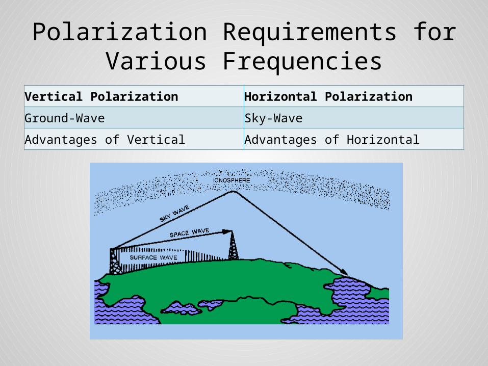
Polarization Requirements for Various Frequencies
Vertical Polarization Horizontal Polarization
Ground-Wave Sky-Wave
Advantages of Vertical Advantages of Horizontal

Propagation Characteristics
• Diffraction– Bending of ground wave around dense objects

Propagation Characteristics
• Reflection– Encountering very dense objects

Propagation Characteristics
• Refraction– Moving through dense mediums

Propagation Characteristics
• Scatter– Reflection off uneven surfaces

Principles of Radiation
• Electromagnetic Fields• Importance of Design• Two Basic Types of Antennas
– Hertz– Marconi
• Antenna Parts– Coupling Device– Feeder– Antenna

Principles of Radiation
• Current and Voltage Distribution• ‘Laws’ of radiation of electrometric energy
– A moving electric field creates a magnetic field (H)– A moving magnetic field creates an electric field
(E)

Polarization Requirements for Various Frequencies
• Ground-Wave • Sky-wave• Advantages of Vertical • Advantages of Vertical Polarization• Advantages of Horizontal Polarization

Common Units of Measure• Ampere (amp)
– Charge from 6.241 x10¹⁸ electrons in 1 second• Volt (V)
– one amp (A) dissipates one watt (W) of power• Decibel (dB)
– Relative unit of measure• dB (isotropic) (dBi)
– Forward gain of antenna compared to theoretical • Watt (W)
– One amp at one volt

References• Integrated Publishing Electrical Engineering Training Series
http://www.tpub.com/neets/book10/42• Electronic Communications 3rd Edition• Radio Handbook 23rd Edition• Understanding Antennas For the Non-Technical Ham
http://www.hamuniverse.com/basicantennas.pdf


![Design of Ionofree Micro Strip Quad Helix Antenna for ... · antenna, bifilar helices antenna, microstrip antenna, quadrafilar helix antenna. ... Helical antenna [1],[2] is broadband](https://img.pdfslide.us/doc/110x75/5b9506e809d3f2ea5c8b5a04/design-of-ionofree-micro-strip-quad-helix-antenna-for-antenna-bifilar-helices.jpg)