Embed Size (px)
DESCRIPTION
Radiation damage in the STAR environment and performance of MAPS sensors. Compilation of different test results mostly from Michael’s thesis. Outline. What can we expect at STAR? Figure of merit – S/N Ionizing radiation effects Non-ionizing radiation effects Simple noise model - PowerPoint PPT Presentation
Citation preview

IPHC-LBNL meeting
3-5 April 2008
Radiation damage in the STAR environment and performance of MAPS
sensors
Compilation of different test results mostly from Michael’s thesis
M.S. IPHC-LBNL meeting, 3-5 April 2008
22
Outline
What can we expect at STAR? Figure of merit – S/N Ionizing radiation effects Non-ionizing radiation effects Simple noise model Some solutions and issues
M.S. IPHC-LBNL meeting, 3-5 April 2008
33
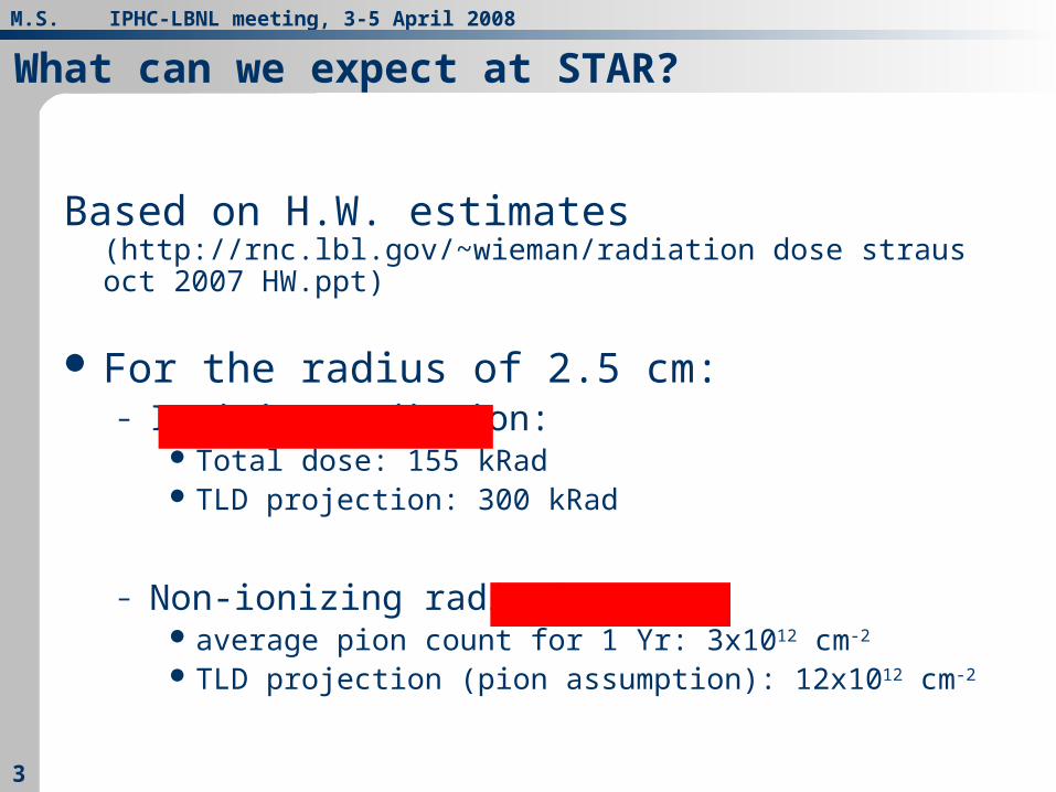
Based on H.W. estimates (http://rnc.lbl.gov/~wieman/radiation dose straus oct 2007 HW.ppt)
For the radius of 2.5 cm:– Ionizing radiation:
Total dose: 155 kRad TLD projection: 300 kRad
– Non-ionizing radiation average pion count for 1 Yr: 3x1012 cm-2
TLD projection (pion assumption): 12x1012 cm-2
What can we expect at STAR?

M.S. IPHC-LBNL meeting, 3-5 April 2008
44
Figure of merit for high detection efficiency is S/N
Test results of MimoSTAR2 show that
– Measured with cuts on clusters– Similar performance can be expected from single threshold algorithm
for S/N>12 detection efficiency >99.6%
M.S. IPHC-LBNL meeting, 3-5 April 2008
55
Ionizing radiation effects
Increased leakage current– Increase of shot noise– Faster discharge time of the self-biased structure that
in extreme cases could lead to signal losses
M.S. IPHC-LBNL meeting, 3-5 April 2008
66
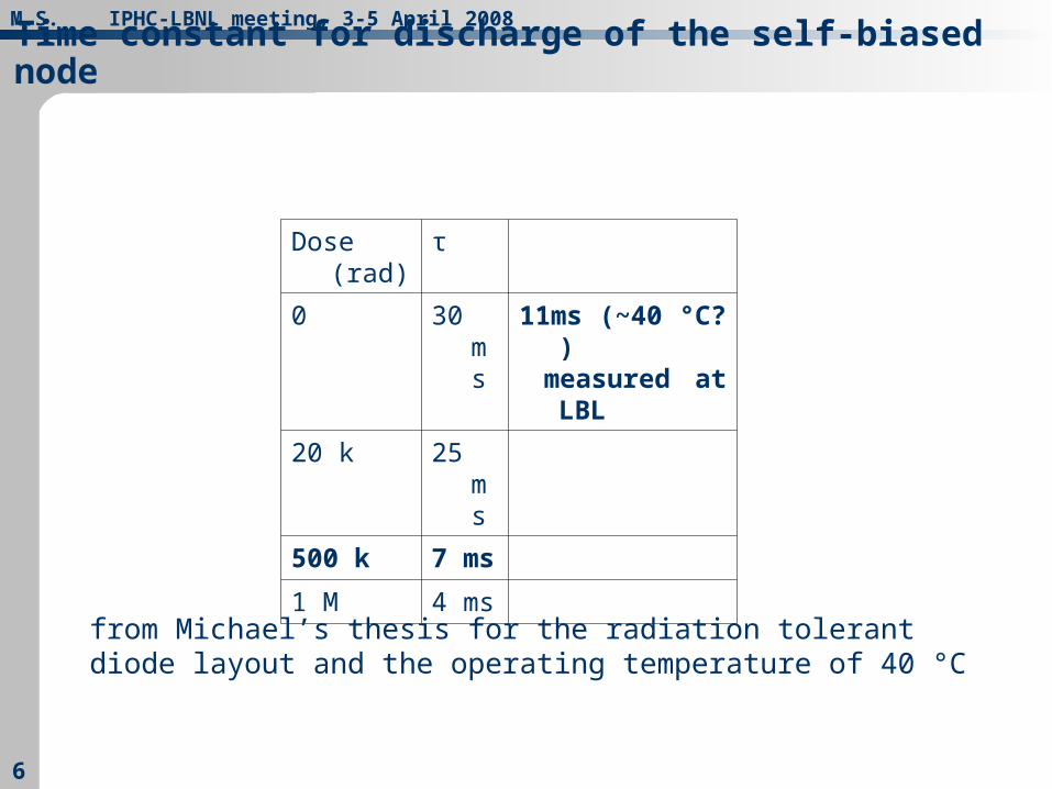
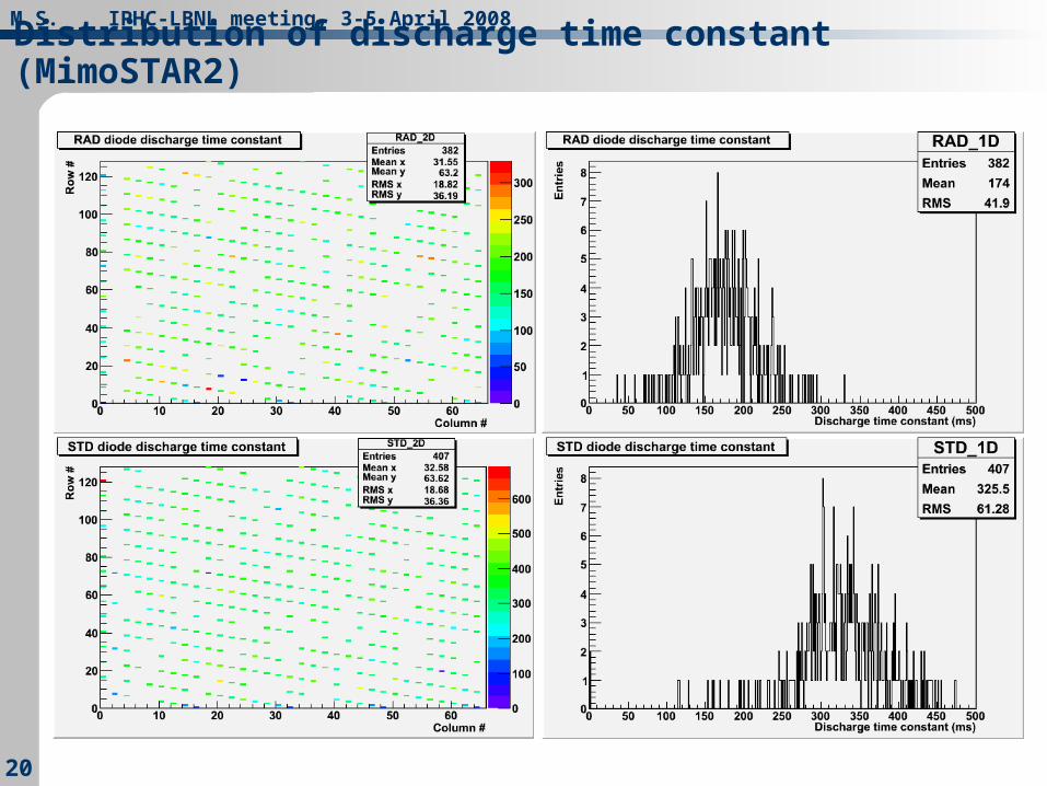
Time constant for discharge of the self-biased node
Dose (rad) τ
0 30 ms 11ms (~40 °C? ) measured at LBL
20 k 25 ms
500 k 7 ms
1 M 4 ms
from Michael’s thesis for the radiation tolerant diode layout and the operating temperature of 40 °C
M.S. IPHC-LBNL meeting, 3-5 April 2008
77
Discharge time
At LBL =130 ms at 30 °C and about 11 ms at the unknown (uncontrolled “ambient”) temperature for a non-irradiated sensor
– the charge collection efficiency (CCE) at the level of 77%, the sensor integration time was 1.7 ms
– at IPHC for the integration time of 4 ms CCE of 75%
short discharge time constant on the order of 10 ms (6 x integration time) did not affect signal collection
Degradation of the discharge time after integrated ionizing dose of a few hundred krad should not be a problem.

M.S. IPHC-LBNL meeting, 3-5 April 2008
88
Non-ionizing radiation
Charge losses due to bulk damage Increased leakage current (not negligible)
– Increase of shot noise
M.S. IPHC-LBNL meeting, 3-5 April 2008
99
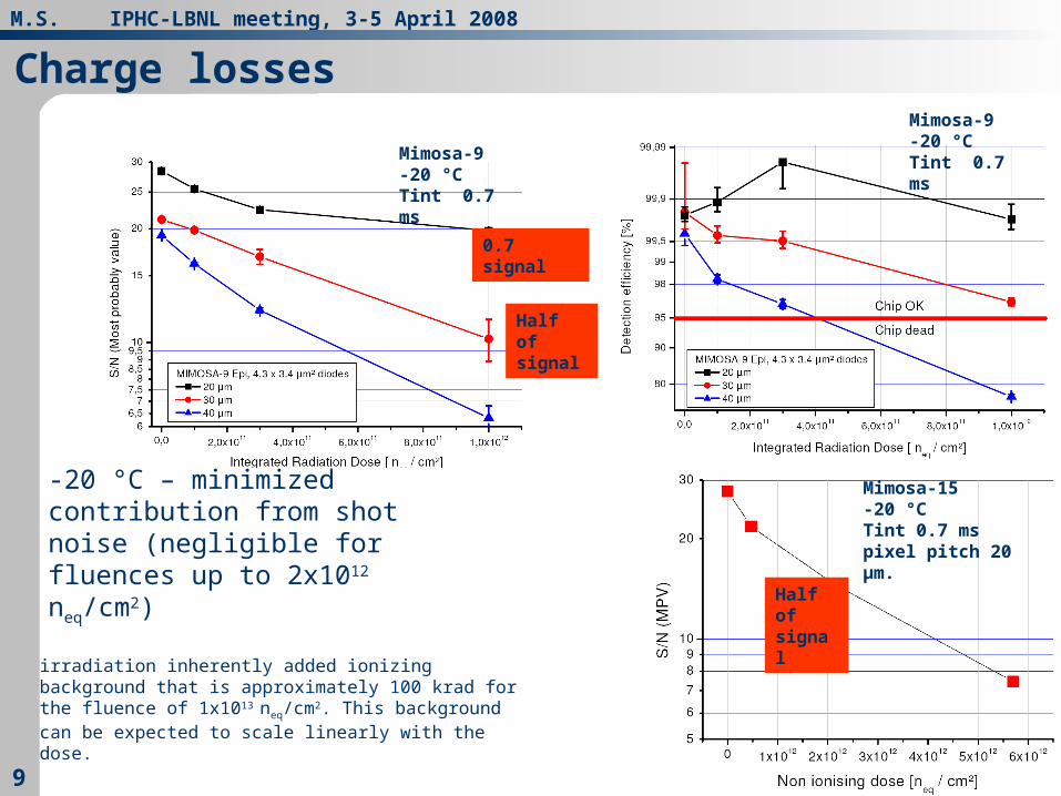
Charge losses
-20 °C – minimized contribution from shot noise (negligible for fluences up to 2x10¹² neq/cm2)
Mimosa-9 -20 °C Tint 0.7 ms
Mimosa-15 -20 °CTint 0.7 ms pixel pitch 20 μm.
Half of signal
0.7 signal
irradiation inherently added ionizing background that is approximately 100 krad for the fluence of 1x10¹³ neq/cm2. This background can be expected to scale linearly with the dose.
Mimosa-9 -20 °C Tint 0.7 ms
Half of signal

M.S. IPHC-LBNL meeting, 3-5 April 2008
1010
Charge collection efficiency (CCE)
Beam Test Calibration of the Mimosa-15 prototype (S. Amar-Youcef, M. Deveaux, M. Goffe – 05.2006) At -20 °C and +20 °C:
– 20 μm pitch and 2.1x10¹² neq/cm2 the CCE decrease to about 0.5– 30 μm pitch (MimoSTAR-like) CCE decreases to
0.66 (4.7 x 10¹¹ neq/cm2) 0.39 (2.1 x 10¹² neq/cm2)
20 °C
50 100 150 200 250 300 350ADC
0.2
0.4
0.6
0.8
1Entries
black chipRef, blue chip4, purple chip6, red chip10, green chip1120 °C
50 100 150 200 250 300 350ADC
0.2
0.4
0.6
0.8
1Entries
black chipRef, blue chip4, purple chip6, red chip10, green chip11
20 °C
50 100 150 200 250 300 350ADC
0.2
0.4
0.6
0.8
1Entries
black chipRef, blue chip4, purple chip6, red chip10, green chip1120 °C
50 100 150 200 250 300 350ADC
0.2
0.4
0.6
0.8
1Entries
black chipRef, blue chip4, purple chip6, red chip10, green chip11
Black: RefBlue: 4.7x10¹¹
Purple: 2.1x10¹²
Red: 5.8x10¹²
Green: 1.1x10¹³
MimoSTAR2 pixel type
M.S. IPHC-LBNL meeting, 3-5 April 2008
1111
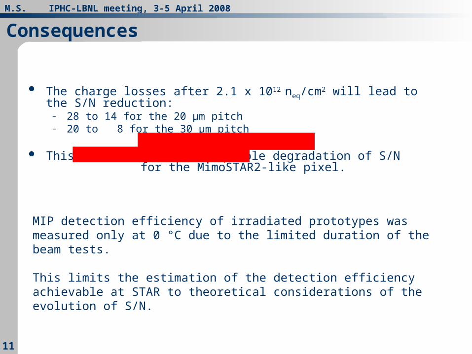
Consequences
The charge losses after 2.1 x 10¹² neq/cm2 will lead to the S/N reduction:– 28 to 14 for the 20 μm pitch– 20 to 8 for the 30 μm pitch
This results in an unacceptable degradation of S/N for the MimoSTAR2-like pixel.
MIP detection efficiency of irradiated prototypes was measured only at 0 °C due to the limited duration of the beam tests.
This limits the estimation of the detection efficiency achievable at STAR to theoretical considerations of the evolution of S/N.

M.S. IPHC-LBNL meeting, 3-5 April 2008
1212
Leakage current (noise) from bulk damage
0
5
10
15
20
25
30
35
40
-20 0 20 40
T °C
no
ise
chip 3
chip 4
chip 5
chip 6
chip 7
chip 8
chip 9
chip 10
chip 11
after 2x10¹² neq/cm2 the noise degrades from 15 to 18 e-
Chip 3 refChip 4 4.7x10¹¹
Chip 6 2.1x10¹²
Chip 10 5.8x10¹²
Chip 11 1.1x10¹³ Chip 5 refChip 7 23 krad γChip 8 20 krad XChip 9 1 Mrad X
3T pitch 20 μm SB pitch 30 μm.
M.S. IPHC-LBNL meeting, 3-5 April 2008
1313
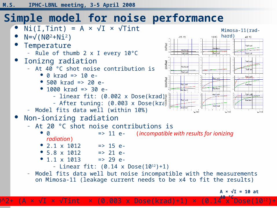
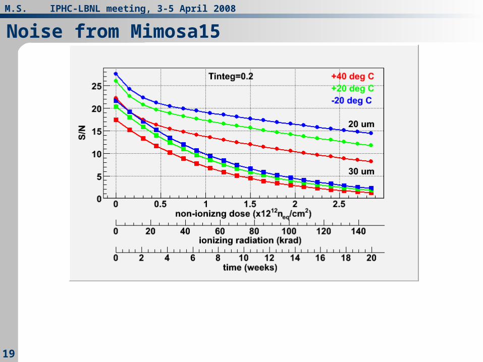
Ni(I,Tint) = A × √I × √Tint N=√(N02+Ni2) Temperature
– Rule of thumb 2 x I every 10°C Ionizng radiation
– At 40 °C shot noise contribution is 0 krad => 10 e- 500 krad => 20 e- 1000 krad => 30 e-
– linear fit: (0.002 x Dose(krad)+1)– After tuning: (0.003 x Dose(krad)+1)
– Model fits data well (within 10%) Non-ionizing radiation
– At 20 °C shot noise contributions is 0 => 11 e- (incompatible with results for ionizing radiation) 2.1 x 1012 => 15 e- 5.8 x 1012 => 21 e- 1.1 x 1013 => 29 e-
– Linear fit: (0.14 x Dose(1012)+1)– Model fits data well but noise incompatible with the measurements on Mimosa-11
(leakage current needs to be x4 to fit the results)
Simple model for noise performanceMimosa-11(rad-hard)
N=√(N0^2+ (A × √I × √Tint × (0.003 x Dose(krad)+1) × (0.14 x Dose(1012)+1))^2)
A × √I = 10 at 40 °C

M.S. IPHC-LBNL meeting, 3-5 April 2008
1414
Simple model for charge losses
Exponential dependency?

M.S. IPHC-LBNL meeting, 3-5 April 2008
1515
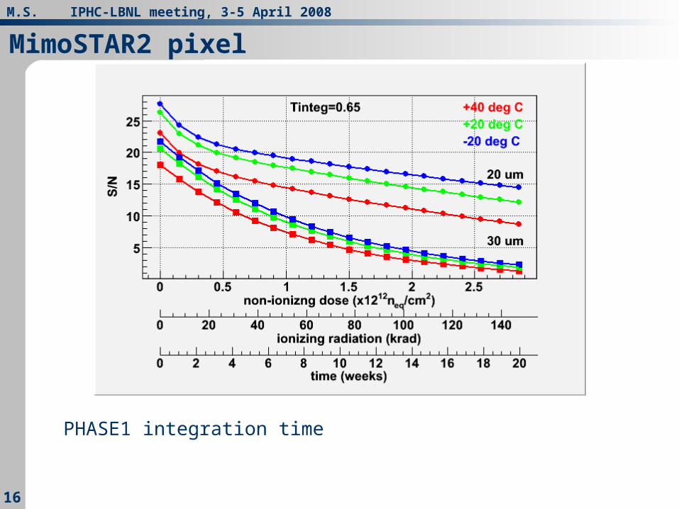
MimoSTAR2 pixel
Single detector replacement – not sufficient Full elimination of shot noise – not sufficient Annealing ?
M.S. IPHC-LBNL meeting, 3-5 April 2008
1616
MimoSTAR2 pixel
PHASE1 integration time
M.S. IPHC-LBNL meeting, 3-5 April 2008
1717
Solutions
Decrease pixel pitch to 20 μm– # columns x 1.5 => power dissipation x 1.5– column length x 1.5 => integration time unchanged
SUZE can not run faster than designed (160 ns) Cluster size?
– Signal decrease to 0.5 from non-ionizing radiation damage (2.1 x 10¹² neq/cm2)
– And noise increase 1.15 @ 0.2 ms integration time (assumption for 155 krad @ 40 °C)
– S/N goes down to about 0.44 (28 =>12) it looks OK but what is the accuracy of these estimations? (detector replacement S/N~16)
M.S. IPHC-LBNL meeting, 3-5 April 2008
1818
Other solutions
Smaller pixel pitch (15, 18 μm) (power dissipation?) 30 μm pitch with multiple charge collecting diodes?
Graded substrate (!) Deep P implants
Latch up in SUZE and Mimosa22 needs to be investigated Hot pixels after non-ionizing irradiation (Function of dose?
Annealing?)– How to mask them for SUZE?
Irradiations with pions?
Other issues
M.S. IPHC-LBNL meeting, 3-5 April 2008
1919
Noise from Mimosa15
M.S. IPHC-LBNL meeting, 3-5 April 2008
2020
Distribution of discharge time constant (MimoSTAR2)