Embed Size (px)
Citation preview
W/KSP/v.8ES-EN 1
VM.Z. spol. s r.o. HEATING*VENTILATION*CONTROL
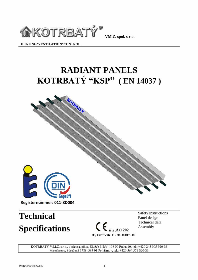
RADIANT PANELS
KOTRBATÝ “KSP” ( EN 14037 )
Technical
Specifications 1015 ,AO 202
05, Certificate: E - 30 - 00017 - 05
Safety instructions
Panel design
Technical data
Assembly
KOTRBATÝ V.M.Z. s.r.o., Technical office, Služeb 5/256, 108 00 Praha 10, tel.: +420 245 005 920-33
Manufacture, Sdružená 1788, 393 01 Pelhřimov, tel.: +420 564 571 520-33
KOTRBATÝ HEATING-VENTILATION-CONTROL
KSP Radiant Panel
W/KSP/v.8ES-EN 2
Page
Contents: 1. Characteristics 3
2. Symbols used in the documentation 3
3. Safety instructions 3
4. General regulations and provisions 4
5. Type description 4
6. Purpose 5
7. Panel design 5
8. Basic dimensions of the individual panels 6
9. Technical data 7
10. Thermal output control 10
11. Distribution of the radiant panels 10
12. Creation of the heating surface 11
13. Assembly and installation of the radiant panels 14
13.1 Instructions for assembly of the radiant panels 14
13.2 Completion elements 19
14. Safe distances 22
15. Packing 22
16. Disposal of the package and product after the end of their
lifetime 22
17. Transport 22
18. Contact addresses 22
KOTRBATÝ HEATING-VENTILATION-CONTROL
KSP Radiant Panel
W/KSP/v.8ES-EN 3
1. Characteristics
In principle, radiant heating with the use of
suspended panels is more economical than
hot-air systems and at the same time, it
provides for better micro-climatic conditions.
Radiant panels enable significant reductions
of heat consumption in combination with
suitable ventilation systems that bring air
directly to the occupied areas at low speeds
and with a lower temperature of released air
than the air temperature in the working area.
Radiant heating ensures convenience. A great
benefit of the radiant panels is the minimum
requirement for maintenance. A modular
radiant heating system allows you to create
any radiant surface suspended under the roof
shell, both longitudinally and transversely.
Panels that are welded together in bands serve
as a heating surface as well as a distribution
pipeline.
The radiant surface is made of sheet
aluminum, which has high heat conductivity
and ensures the high average mean
temperature of the surface. The quality of the
surface finish is very high and the color shade
does not change or the surface does not
become damaged even under extreme
temperatures.
2. Symbols used in the
documentation
This symbol draws your
attention to the careful
observance of the instructions in
the text.
CAUTION! This symbol refers to important
instructions or to the possible
consequences of the non-
observance of these
instructions.
3. Safety regulations
This documentation contains basic
instructions for the installation of the KSP
radiant panels.
CAUTION! Before installation and the
commissioning of the
system, it is absolutely
necessary for the installation
technicians to read this
documentation thoroughly.
Besides the instructions mentioned here, it is
naturally necessary to observe the valid
regulations, directives and local standards.
The system may only be put into operation
after the completion of all the prescribed tests
for systems of hot-water (or steam) heating.
If steam is used as the
heating medium, a
corresponding control
system must be installed and
the system may only be
operated by a qualified and
trained person (attention
must mainly be paid to the
start-up and the shut-down
of the system!!!).
KOTRBATÝ HEATING-VENTILATION-CONTROL
KSP Radiant Panel
W/KSP/v.8ES-EN 4
4. General regulations and
provisions
1. The design and installation of central
heating systems that use water or steam as
the heating medium is subject to the ČSN
06 0310 standard (or other valid standards
or regulations).
2. The design, implementation and operation
of the safety equipment for systems of
central heating and the heating of hot
water is subject to the ČSN 06 0830
standard. A central heating or hot-water
heating system must not be put into
operation without this safety equipment.
3. Every assembled piece of equipment must
be tested before it is put into operation
(see ČSN 06 0310 or other valid standards
or regulations).
4. Installation may only be carried out by
qualified technicians. During the
installation, the technicians are obliged to
observe work safety rules and to proceed
in such a way as to not damage the
equipment. The guarantee terms do not
cover damages caused in this way. The
installation must be carried out in
accordance with the design documentation
as well as the valid regulations, standards
and directives.
5. The radiant panels must be stored in such
a way as to be protected from climatic
influences, chemical substances,
mechanical damage or unauthorized
handling (they should be stored in roofed,
lockable and dry spaces). If the customer
stores the panels for a period longer than 3
months, the storage is subject to the
provisions of ČSN 03 8205.
6. The radiant heating system may only be
connected if the parameters of the heating
water or steam (pressure, temperature)
correspond to the technical data
mentioned in the documentation and it
may only be operated in accordance with
the valid standards, regulations and
directives! The connection must be
established in accordance with the design
documentation. The whole heating system
must not be put into operation without
safety equipment.
5. Type description
The radiant panels are made of shaped
aluminum lamellas with inserted steel pipes
and with yokes they are connected with
consoles that are used to align the side wings
at the same time. The system consists of
panels made of basic modules with a width of
150 mm that are connected to the required
width with the use of consoles. The basic
element of the radiant panel is a 28 x 1.5 steel
pipe that leads the heating medium and is
connected to the radiant sheet aluminum (in
various colors) of the lower part of the panel.
The design of the panels makes it possible to
supply panels of different colors, but with
regard to architects’ ideas, it is also possible
to combine modules of various colors in one
panel. The heating media are: hot water up to
the temperature of 140 °C and a pressure of
1.6 MPa, steam up to the temperature of
150 °C and a pressure of 0.5 MPa.
KOTRBATÝ HEATING-VENTILATION-CONTROL
KSP Radiant Panel
W/KSP/v.8ES-EN 5
6. Purpose
The system is used for the heating of large
indoor spaces such as industrial halls,
gymnasiums, sports halls, shops,
marketplaces, warehouse buildings, etc. The
temperature under the roof shell, which is
generally the largest cooled area of the heated
space, has the decisive influence on the
economy of operation.
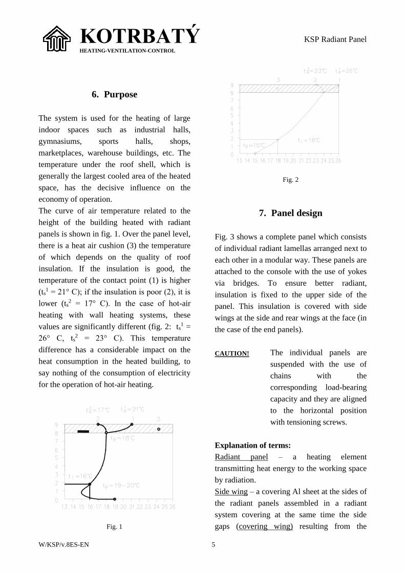
The curve of air temperature related to the
height of the building heated with radiant
panels is shown in fig. 1. Over the panel level,
there is a heat air cushion (3) the temperature
of which depends on the quality of roof
insulation. If the insulation is good, the
temperature of the contact point (1) is higher
(ts1 = 21° C); if the insulation is poor (2), it is
lower (ts2 = 17° C). In the case of hot-air
heating with wall heating systems, these
values are significantly different (fig. 2: ts1 =
26° C, ts2 = 23° C). This temperature
difference has a considerable impact on the
heat consumption in the heated building, to
say nothing of the consumption of electricity
for the operation of hot-air heating.
Fig. 1
Fig. 2
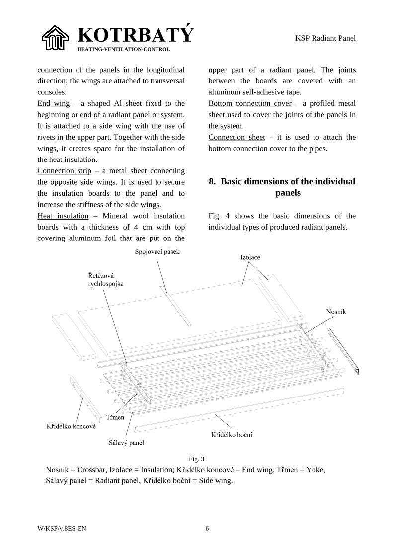
7. Panel design
Fig. 3 shows a complete panel which consists
of individual radiant lamellas arranged next to
each other in a modular way. These panels are
attached to the console with the use of yokes
via bridges. To ensure better radiant,
insulation is fixed to the upper side of the
panel. This insulation is covered with side
wings at the side and rear wings at the face (in
the case of the end panels).
CAUTION! The individual panels are
suspended with the use of
chains with the
corresponding load-bearing
capacity and they are aligned
to the horizontal position
with tensioning screws.
Explanation of terms:
Radiant panel – a heating element
transmitting heat energy to the working space
by radiation.
Side wing – a covering Al sheet at the sides of
the radiant panels assembled in a radiant
system covering at the same time the side
gaps (covering wing) resulting from the
KOTRBATÝ HEATING-VENTILATION-CONTROL
KSP Radiant Panel
W/KSP/v.8ES-EN 6
connection of the panels in the longitudinal
direction; the wings are attached to transversal
consoles.
End wing – a shaped Al sheet fixed to the
beginning or end of a radiant panel or system.
It is attached to a side wing with the use of
rivets in the upper part. Together with the side
wings, it creates space for the installation of
the heat insulation.
Connection strip – a metal sheet connecting
the opposite side wings. It is used to secure
the insulation boards to the panel and to
increase the stiffness of the side wings.
Heat insulation – Mineral wool insulation
boards with a thickness of 4 cm with top
covering aluminum foil that are put on the
upper part of a radiant panel. The joints
between the boards are covered with an
aluminum self-adhesive tape.
Bottom connection cover – a profiled metal
sheet used to cover the joints of the panels in
the system.
Connection sheet – it is used to attach the
bottom connection cover to the pipes.
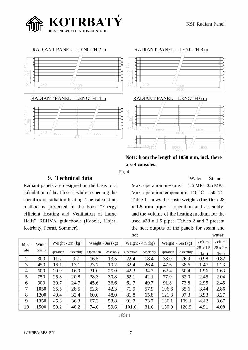
8. Basic dimensions of the individual
panels
Fig. 4 shows the basic dimensions of the
individual types of produced radiant panels.
Řetězová
rychlospojka
Nosník
IzolaceSpojovací pásek
Třmen
Sálavý panel
Křidélko koncové
Křidélko boční
Fig. 3
Nosník = Crossbar, Izolace = Insulation; Křidélko koncové = End wing, Třmen = Yoke,
Sálavý panel = Radiant panel, Křidélko boční = Side wing.
KOTRBATÝ HEATING-VENTILATION-CONTROL
KSP Radiant Panel
W/KSP/v.8ES-EN 7
RADIANT PANEL – LENGTH 2 m
RADIANT PANEL – LENGTH 3 m
RADIANT PANEL – LENGTH 4 m
RADIANT PANEL – LENGTH 6 m
Note: from the length of 1050 mm, incl. there
are 4 consoles!
Fig. 4
9. Technical data
Radiant panels are designed on the basis of a
calculation of heat losses while respecting the
specifics of radiation heating. The calculation
method is presented in the book “Energy
efficient Heating and Ventilation of Large
Halls” REHVA guidebook (Kabele, Hojer,
Kotrbatý, Petráš, Sommer).
Water Steam
Max. operation pressure: 1.6 MPa 0.5 MPa
Max. operation temperature: 140 °C 150 °C
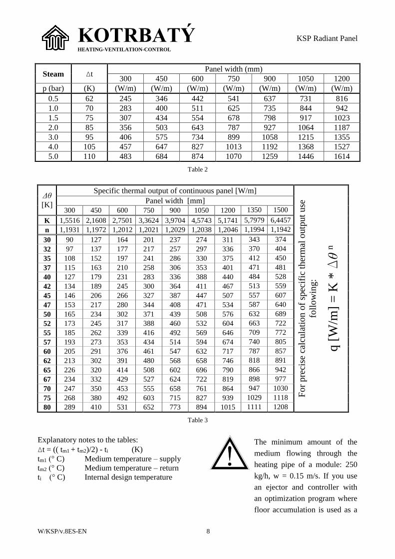
Table 1 shows the basic weights (for the ø28
x 1.5 mm pipes – operation and assembly)
and the volume of the heating medium for the
used ø28 x 1.5 pipes. Tables 2 and 3 present
the heat outputs of the panels for steam and
hot water.
Mod-
ule
Width
(mm)
Weight - 2m (kg) Weight - 3m (kg) Weight - 4m (kg) Weight - 6m (kg) Volume
28 x 1.5
(l/m)
Volume
28 x 2.6
(l/m) Operation Assembly Operation Assembly Operation Assembly Operation Assembly
2 300 11.2 9.2 16.5 13.5 22.4 18.4 33.0 26.9 0.98 0.82
3 450 16.1 13.1 23.7 19.2 32.4 26.4 47.6 38.6 1.47 1.23
4 600 20.9 16.9 31.0 25.0 42.3 34.3 62.4 50.4 1.96 1.63
5 750 25.8 20.8 38.3 30.8 52.1 42.1 77.0 62.0 2.45 2.04
6 900 30.7 24.7 45.6 36.6 61.7 49.7 91.8 73.8 2.95 2.45
7 1050 35.5 28.5 52.8 42.3 71.9 57.9 106.6 85.6 3.44 2.86
8 1200 40.4 32.4 60.0 48.0 81.8 65.8 121.3 97.3 3.93 3.27
9 1350 45.3 36.3 67.3 53.8 91.7 73.7 136.1 109.1 4.42 3.67
10 1500 50.2 40.2 74.6 59.6 101.6 81.6 150.9 120.9 4.91 4.08
Table 1
KOTRBATÝ HEATING-VENTILATION-CONTROL
KSP Radiant Panel
W/KSP/v.8ES-EN 8
Steam Δt Panel width (mm)
300 450 600 750 900 1050 1200
p (bar) (K) (W/m) (W/m) (W/m) (W/m) (W/m) (W/m) (W/m)
0.5 62 245 346 442 541 637 731 816
1.0 70 283 400 511 625 735 844 942
1.5 75 307 434 554 678 798 917 1023
2.0 85 356 503 643 787 927 1064 1187
3.0 95 406 575 734 899 1058 1215 1355
4.0 105 457 647 827 1013 1192 1368 1527
5.0 110 483 684 874 1070 1259 1446 1614
Table 2
Δθ
[K]
Specific thermal output of continuous panel [W/m]
Fo
r pre
cise
cal
cula
tion
of
spec
ific
ther
mal
outp
ut
use
foll
ow
ing:
q [
W/m
] =
K *
Dθ n
Panel width [mm]
300 450 600 750 900 1050 1200 1350 1500
K 1,5516 2,1608 2,7501 3,3624 3,9704 4,5743 5,1741 5,7979 6,4457
n 1,1931 1,1972 1,2012 1,2021 1,2029 1,2038 1,2046 1,1994 1,1942
30 90 127 164 201 237 274 311 343 374
32 97 137 177 217 257 297 336 370 404
35 108 152 197 241 286 330 375 412 450
37 115 163 210 258 306 353 401 471 481
40 127 179 231 283 336 388 440 484 528
42 134 189 245 300 364 411 467 513 559
45 146 206 266 327 387 447 507 557 607
47 153 217 280 344 408 471 534 587 640
50 165 234 302 371 439 508 576 632 689
52 173 245 317 388 460 532 604 663 722
55 185 262 339 416 492 569 646 709 772
57 193 273 353 434 514 594 674 740 805
60 205 291 376 461 547 632 717 787 857
62 213 302 391 480 568 658 746 818 891
65 226 320 414 508 602 696 790 866 942
67 234 332 429 527 624 722 819 898 977
70 247 350 453 555 658 761 864 947 1030
75 268 380 492 603 715 827 939 1029 1118
80 289 410 531 652 773 894 1015 1111 1208
Table 3
Explanatory notes to the tables:
Δt = (( tm1 + tm2)/2) - ti (K)
tm1 (° C) Medium temperature – supply
tm2 (° C) Medium temperature – return
ti (° C) Internal design temperature
The minimum amount of the
medium flowing through the
heating pipe of a module: 250
kg/h, w = 0.15 m/s. If you use
an ejector and controller with
an optimization program where
floor accumulation is used as a
KOTRBATÝ HEATING-VENTILATION-CONTROL
KSP Radiant Panel
W/KSP/v.8ES-EN 9
secondary heating surface in the
system, the calculated output
may be increased by 5 %.
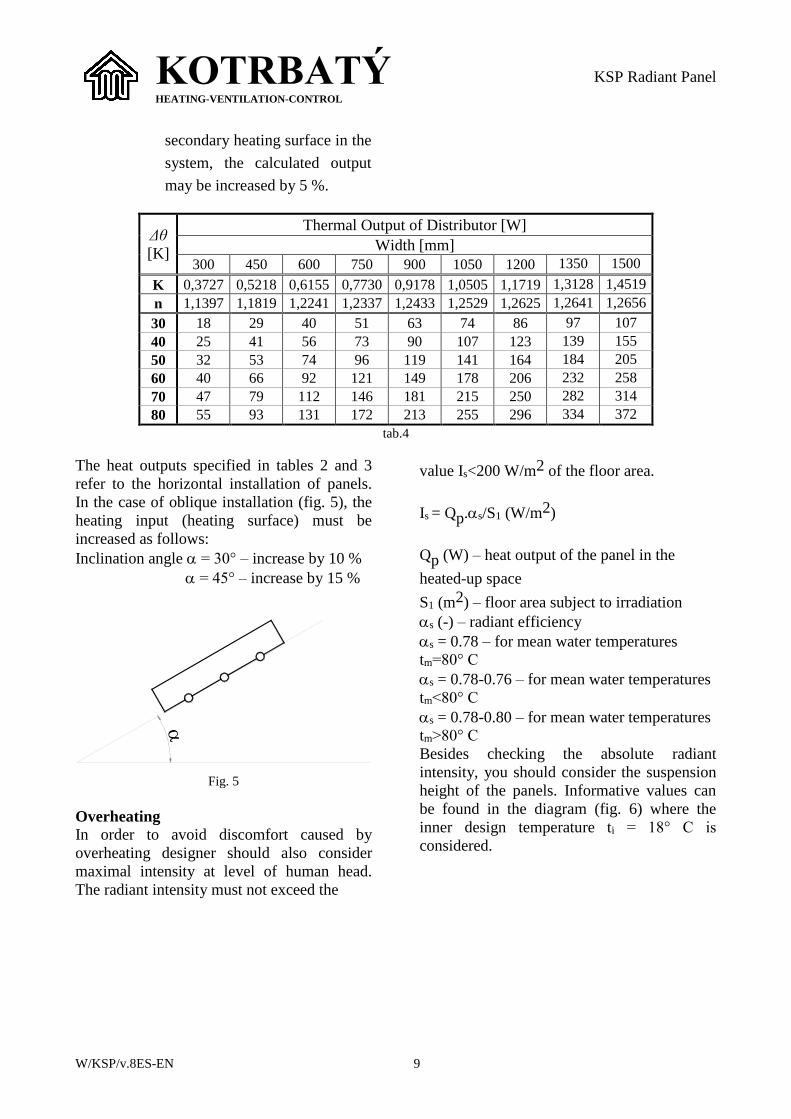
Δθ
[K]
Thermal Output of Distributor [W]
Width [mm]
300 450 600 750 900 1050 1200 1350 1500
K 0,3727 0,5218 0,6155 0,7730 0,9178 1,0505 1,1719 1,3128 1,4519
n 1,1397 1,1819 1,2241 1,2337 1,2433 1,2529 1,2625 1,2641 1,2656
30 18 29 40 51 63 74 86 97 107
40 25 41 56 73 90 107 123 139 155
50 32 53 74 96 119 141 164 184 205
60 40 66 92 121 149 178 206 232 258
70 47 79 112 146 181 215 250 282 314
80 55 93 131 172 213 255 296 334 372
tab.4
The heat outputs specified in tables 2 and 3
refer to the horizontal installation of panels.
In the case of oblique installation (fig. 5), the
heating input (heating surface) must be
increased as follows:
Inclination angle = 30° – increase by 10 %
= 45° – increase by 15 %
Fig. 5
Overheating
In order to avoid discomfort caused by
overheating designer should also consider
maximal intensity at level of human head.
The radiant intensity must not exceed the
value Is<200 W/m2 of the floor area.
Is = Qp.s/S1 (W/m2)
Qp (W) – heat output of the panel in the
heated-up space
S1 (m2) – floor area subject to irradiation
s (-) – radiant efficiency
s = 0.78 – for mean water temperatures
tm=80° C
s = 0.78-0.76 – for mean water temperatures
tm<80° C
s = 0.78-0.80 – for mean water temperatures
tm>80° C
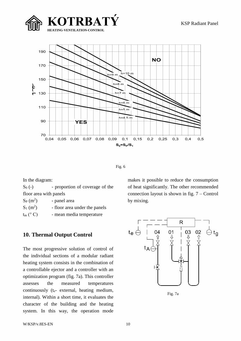
Besides checking the absolute radiant
intensity, you should consider the suspension
height of the panels. Informative values can
be found in the diagram (fig. 6) where the
inner design temperature ti = 18° C is
considered.
KOTRBATÝ HEATING-VENTILATION-CONTROL
KSP Radiant Panel
W/KSP/v.8ES-EN 10
70
90
110
130
150
170
190
0,04 0,05 0,06 0,07 0,08 0,09 0,1 0,15 0,2 0,25 0,3 0,4 0,5
tm(°C)
S0=SP/S1
h=9 m h=10 m
h=8 m
h=7 m
h=6 m
h=5 m
h=4,5 m
NO
YES
Fig. 6
In the diagram:
S0 (-) - proportion of coverage of the
floor area with panels
SP (m2) - panel area
S1 (m2) - floor area under the panels
tm (° C) - mean media temperature
10. Thermal Output Control
The most progressive solution of control of
the individual sections of a modular radiant
heating system consists in the combination of
a controllable ejector and a controller with an
optimization program (fig. 7a). This controller
assesses the measured temperatures
continuously (te- external, heating medium,
internal). Within a short time, it evaluates the
character of the building and the heating
system. In this way, the operation mode
makes it possible to reduce the consumption
of heat significantly. The other recommended
connection layout is shown in fig. 7 – Control
by mixing.
Fig. 7a
KOTRBATÝ HEATING-VENTILATION-CONTROL
KSP Radiant Panel
W/KSP/v.8ES-EN 11
Fig. 7b
obr. 7c
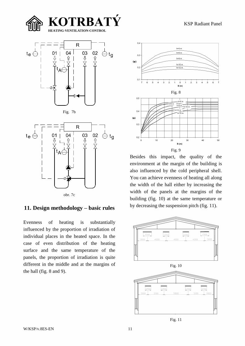
11. Design methodology – basic rules
Evenness of heating is substantially
influenced by the proportion of irradiation of
individual places in the heated space. In the
case of even distribution of the heating
surface and the same temperature of the
panels, the proportion of irradiation is quite
different in the middle and at the margins of
the hall (fig. 8 and 9).
0,1
0,2
0,3
0,4
7 6 5 4 3 2 1 0 1 2 3 4 5 6 7
B (m)
h=5 m
h=6 m
h=8 m
h=10 m
h=12 m
Fig. 8
0,2
0,3
0,4
0,5
0 10 20 30 40 50
B (m)
h=15 m
h=12 m
h=10 mh=8 m
h=6 m
h=5 m
Fig. 9
Besides this impact, the quality of the
environment at the margin of the building is
also influenced by the cold peripheral shell.
You can achieve evenness of heating all along
the width of the hall either by increasing the
width of the panels at the margins of the
building (fig. 10) at the same temperature or
by decreasing the suspension pitch (fig. 11).
Fig. 10
Fig. 11
KOTRBATÝ HEATING-VENTILATION-CONTROL
KSP Radiant Panel
W/KSP/v.8ES-EN 12
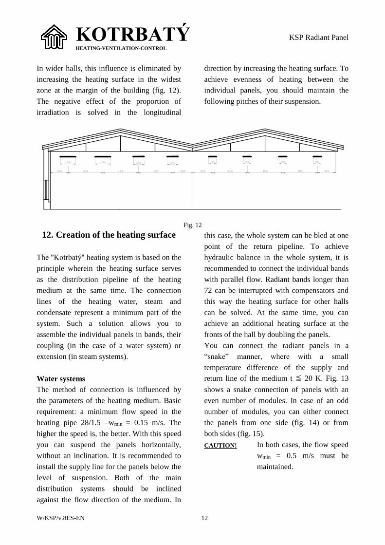
In wider halls, this influence is eliminated by
increasing the heating surface in the widest
zone at the margin of the building (fig. 12).
The negative effect of the proportion of
irradiation is solved in the longitudinal
direction by increasing the heating surface. To
achieve evenness of heating between the
individual panels, you should maintain the
following pitches of their suspension.
Fig. 12
12. Creation of the heating surface
The "Kotrbatý" heating system is based on the
principle wherein the heating surface serves
as the distribution pipeline of the heating
medium at the same time. The connection
lines of the heating water, steam and
condensate represent a minimum part of the
system. Such a solution allows you to
assemble the individual panels in bands, their
coupling (in the case of a water system) or
extension (in steam systems).
Water systems
The method of connection is influenced by
the parameters of the heating medium. Basic
requirement: a minimum flow speed in the
heating pipe 28/1.5 –wmin = 0.15 m/s. The
higher the speed is, the better. With this speed
you can suspend the panels horizontally,
without an inclination. It is recommended to
install the supply line for the panels below the
level of suspension. Both of the main
distribution systems should be inclined
against the flow direction of the medium. In
this case, the whole system can be bled at one
point of the return pipeline. To achieve
hydraulic balance in the whole system, it is
recommended to connect the individual bands
with parallel flow. Radiant bands longer than
72 can be interrupted with compensators and
this way the heating surface for other halls
can be solved. At the same time, you can
achieve an additional heating surface at the
fronts of the hall by doubling the panels.
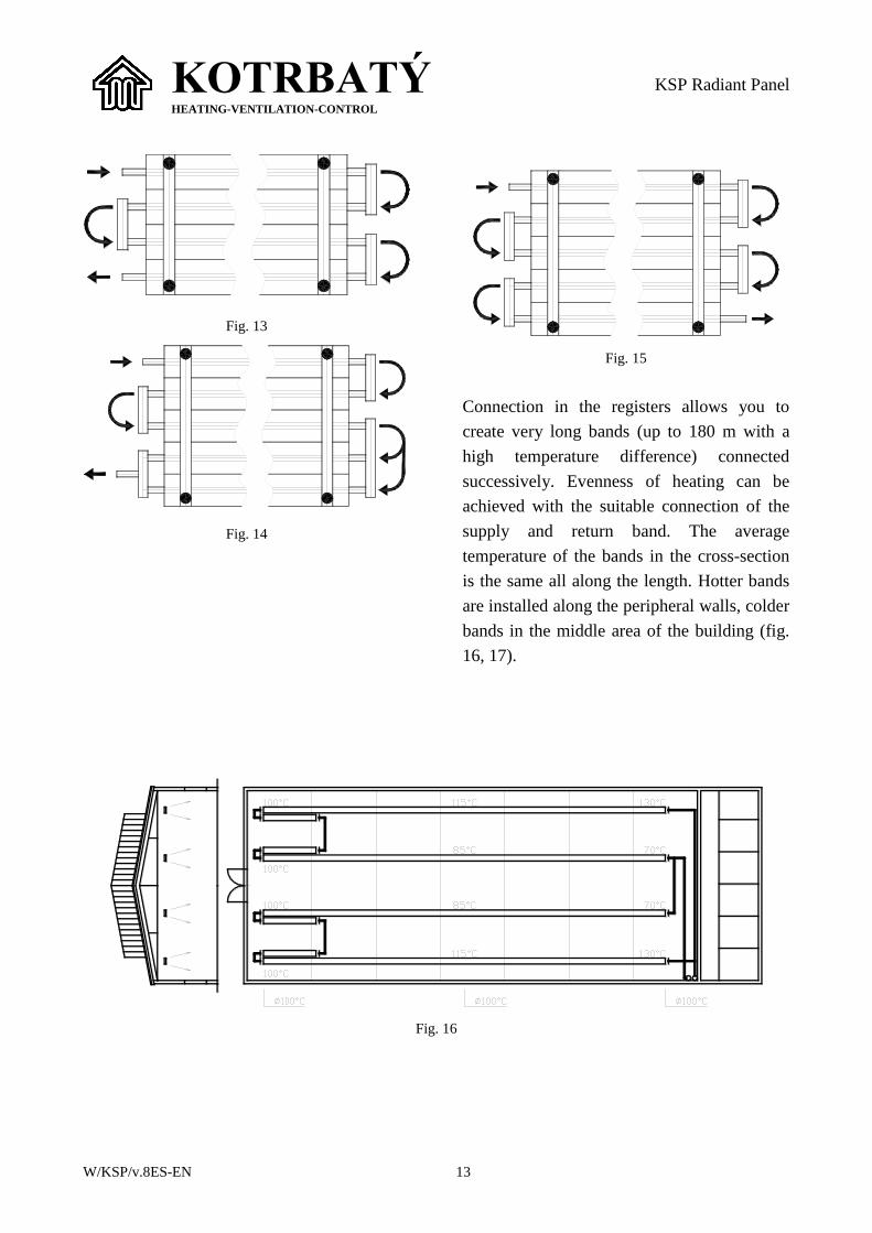
You can connect the radiant panels in a
“snake” manner, where with a small
temperature difference of the supply and
return line of the medium t 20 K. Fig. 13
shows a snake connection of panels with an
even number of modules. In case of an odd
number of modules, you can either connect
the panels from one side (fig. 14) or from
both sides (fig. 15).
CAUTION! In both cases, the flow speed
wmin = 0.5 m/s must be
maintained.
KOTRBATÝ HEATING-VENTILATION-CONTROL
KSP Radiant Panel
W/KSP/v.8ES-EN 13
Fig. 13
Fig. 14
Fig. 15
Connection in the registers allows you to
create very long bands (up to 180 m with a
high temperature difference) connected
successively. Evenness of heating can be
achieved with the suitable connection of the
supply and return band. The average
temperature of the bands in the cross-section
is the same all along the length. Hotter bands
are installed along the peripheral walls, colder
bands in the middle area of the building (fig.
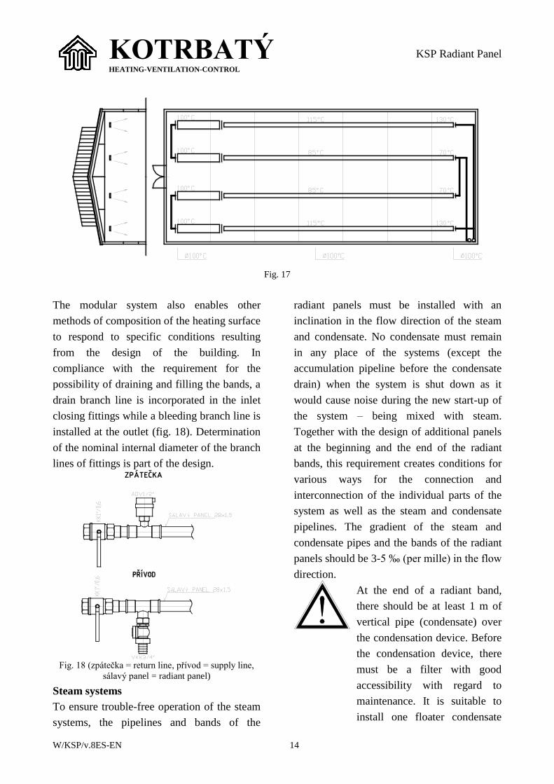
16, 17).
Fig. 16
KOTRBATÝ HEATING-VENTILATION-CONTROL
KSP Radiant Panel
W/KSP/v.8ES-EN 14
Fig. 17
The modular system also enables other
methods of composition of the heating surface
to respond to specific conditions resulting
from the design of the building. In
compliance with the requirement for the
possibility of draining and filling the bands, a
drain branch line is incorporated in the inlet
closing fittings while a bleeding branch line is
installed at the outlet (fig. 18). Determination
of the nominal internal diameter of the branch
lines of fittings is part of the design.
Fig. 18 (zpátečka = return line, přívod = supply line,
sálavý panel = radiant panel)
Steam systems
To ensure trouble-free operation of the steam
systems, the pipelines and bands of the
radiant panels must be installed with an
inclination in the flow direction of the steam
and condensate. No condensate must remain
in any place of the systems (except the
accumulation pipeline before the condensate
drain) when the system is shut down as it
would cause noise during the new start-up of
the system – being mixed with steam.
Together with the design of additional panels
at the beginning and the end of the radiant
bands, this requirement creates conditions for
various ways for the connection and
interconnection of the individual parts of the
system as well as the steam and condensate
pipelines. The gradient of the steam and
condensate pipes and the bands of the radiant
panels should be 3-5 ‰ (per mille) in the flow
direction.
At the end of a radiant band,
there should be at least 1 m of
vertical pipe (condensate) over
the condensation device. Before
the condensation device, there
must be a filter with good
accessibility with regard to
maintenance. It is suitable to
install one floater condensate
KOTRBATÝ HEATING-VENTILATION-CONTROL
KSP Radiant Panel
W/KSP/v.8ES-EN 15
drain for panels of one
production aisle (4 bands = 1
element).
13. Assembly and installation of the
radiant panels
Radiant panels are supplied in two versions:
Complete panels incl. insulation,
Individual elements (modules) –
completed by an assembly company.
The entire panels are produced in the lengths
of 2000, 3000, 4000, 6000 mm and widths of
300, 450, 600, 750, 900, 1050, 1200, 1350
and 1500 mm. They are supplied in the
continuous (P) or terminal (K) version with
one-sided or both-sided (2K) termination. The
end of the panels is equipped with an end
wing. For the assembly of a radiant band,
completion elements are used. The basic
product is a radiant heating surface composed
of modules with a width of 150 mm.
13.1. Instructions for the assembly of
the radiant panels
Safety instructions for the assembly
The assembly work may only be carried out
by the qualified employees of the assembly
firm.
During the assembly, the
relevant technical and safety
regulations and directives must
be observed. The assembly
must correspond to the design
documentation.
During the assembly of the panels, the
assembly firm must fully ensure the safety of
the assembly technicians and people that are
present in the workplaces and adopt all safety
measures to protect the surrounding
equipment from being damaged.
These instructions do not determine the
method of assembly works. This is
determined by the assembly firm and it must
be based on particular applications with
regard to the requirements mentioned below.
1. Before the start of the assembly, it is
suitable to locate the positions of the panel
suspensions and to fix them to the truss
structure of the building or to auxiliary
structures in places where they will be
attached. The suspensions must be
sufficiently dimensioned incl. a reserve
and they must be attached securely.
2. Hang the chains to the suspensions
prepared this way.
These chains must have a
corresponding load-bearing
capacity (including a reserve)
– panel weights – see the
Technical data. The chains must
have a surface finish.
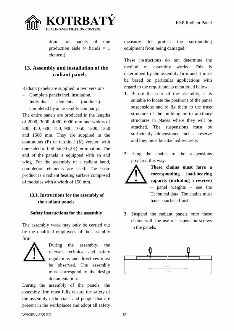
3. Suspend the radiant panels onto these
chains with the use of suspension screws
in the panels.
KOTRBATÝ HEATING-VENTILATION-CONTROL
KSP Radiant Panel
W/KSP/v.8ES-EN 16
CAUTION – from the width of 1050 mm
(inclusive) – 4 consoles!
Fig. 19
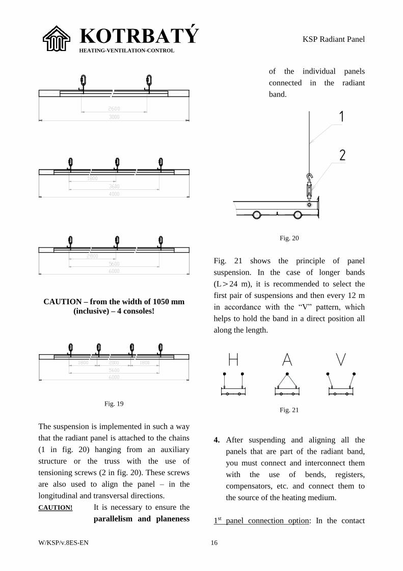
The suspension is implemented in such a way
that the radiant panel is attached to the chains
(1 in fig. 20) hanging from an auxiliary
structure or the truss with the use of
tensioning screws (2 in fig. 20). These screws
are also used to align the panel – in the
longitudinal and transversal directions.
CAUTION! It is necessary to ensure the
parallelism and planeness
of the individual panels
connected in the radiant
band.
Fig. 20
Fig. 21 shows the principle of panel
suspension. In the case of longer bands
(L24 m), it is recommended to select the
first pair of suspensions and then every 12 m
in accordance with the “V” pattern, which
helps to hold the band in a direct position all
along the length.
Fig. 21
4. After suspending and aligning all the
panels that are part of the radiant band,
you must connect and interconnect them
with the use of bends, registers,
compensators, etc. and connect them to
the source of the heating medium.
1st panel connection option: In the contact
KOTRBATÝ HEATING-VENTILATION-CONTROL
KSP Radiant Panel
W/KSP/v.8ES-EN 17
places of the cable pipes, the pipes are welded
while the same holds good for the bends,
compensators, etc. We recommend you to
cool the pipes behind the place of welding so
that the lacquer of the aluminium lamellas
does not get burnt.
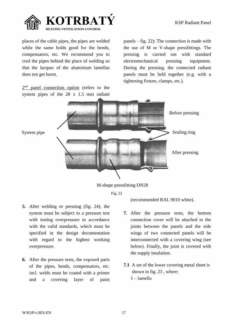
2nd panel connection option (refers to the
system pipes of the 28 x 1.5 mm radiant
panels – fig. 22): The connection is made with
the use of M or V-shape pressfittings. The
pressing is carried out with standard
electromechanical pressing equipment.
During the pressing, the connected radiant
panels must be held together (e.g. with a
tightening fixture, clamps, etc.).
Fig. 22
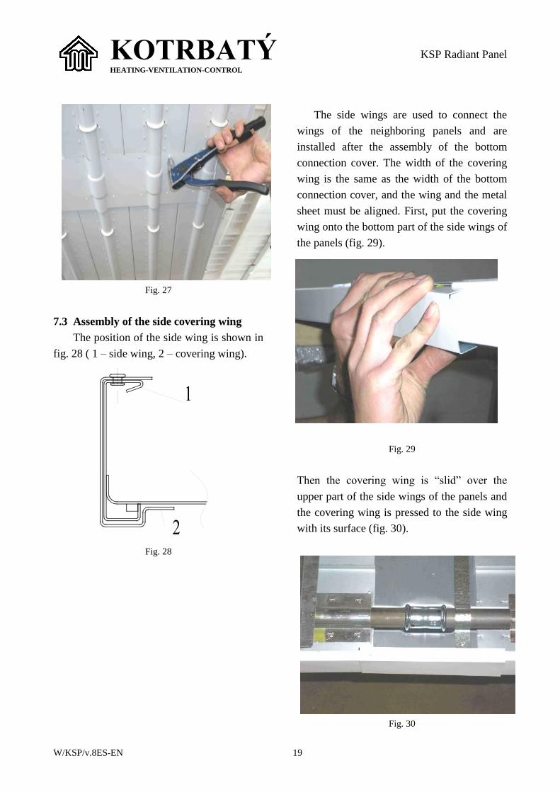
5. After welding or pressing (fig. 24), the
system must be subject to a pressure test
with testing overpressure in accordance
with the valid standards, which must be
specified in the design documentation
with regard to the highest working
overpressure.
6. After the pressure tests, the exposed parts
of the pipes, bends, compensators, etc.
incl. welds must be coated with a primer
and a covering layer of paint
(recommended RAL 9010 white).
7. After the pressure tests, the bottom
connection cover will be attached to the
joints between the panels and the side
wings of two connected panels will be
interconnected with a covering wing (see
below). Finally, the joint is covered with
the supply insulation.
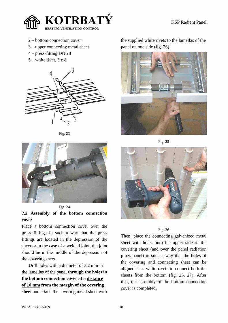
7.1 A set of the lower covering metal sheet is
shown in fig. 23 , where:
1 – lamella
M-shape pressfitting DN28
Sealing ring
Before pressing
After pressing
System pipe
KOTRBATÝ HEATING-VENTILATION-CONTROL
KSP Radiant Panel
W/KSP/v.8ES-EN 18
2 – bottom connection cover
3 – upper connecting metal sheet
4 – press-fitting DN 28
5 – white rivet, 3 x 8
Fig. 23
Fig. 24
7.2 Assembly of the bottom connection
cover
Place a bottom connection cover over the
press fittings in such a way that the press
fittings are located in the depression of the
sheet or in the case of a welded joint, the joint
should be in the middle of the depression of
the covering sheet.
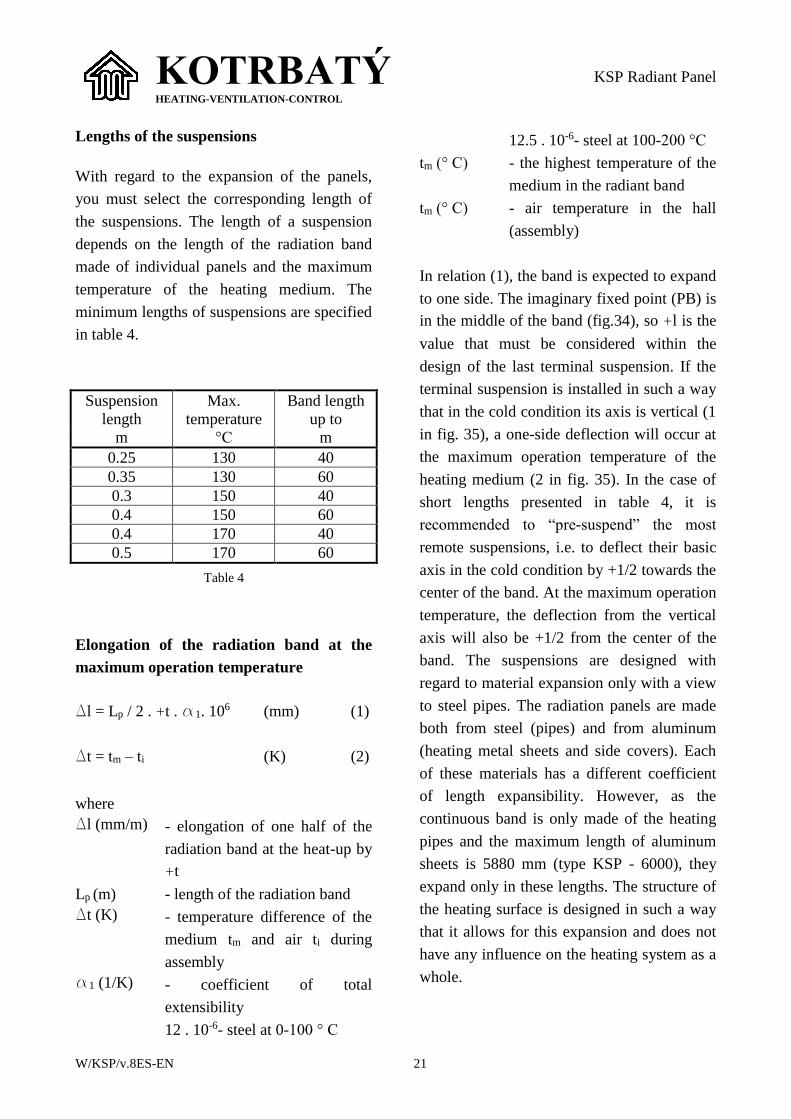
Drill holes with a diameter of 3.2 mm in
the lamellas of the panel through the holes in
the bottom connection cover at a distance
of 10 mm from the margin of the covering
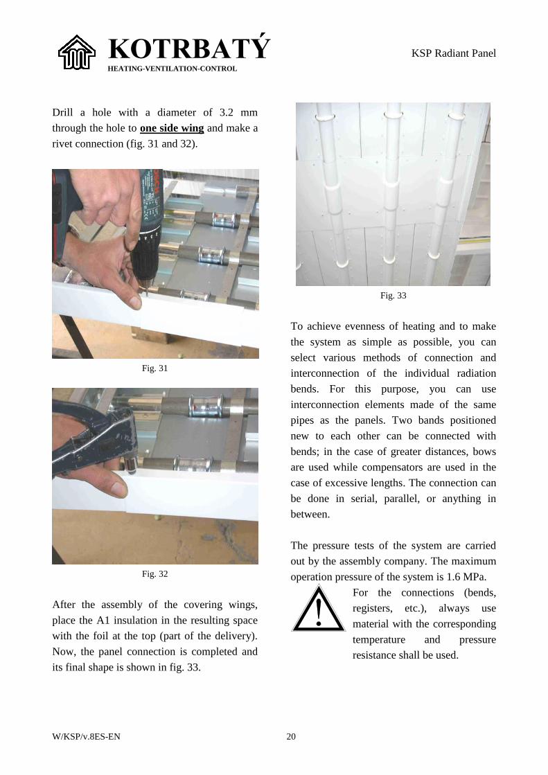
sheet and attach the covering metal sheet with
the supplied white rivets to the lamellas of the
panel on one side (fig. 26).
Fig. 25
Fig. 26
Then, place the connecting galvanized metal
sheet with holes onto the upper side of the
covering sheet (and over the panel radiation
pipes panel) in such a way that the holes of
the covering and connecting sheet can be
aligned. Use white rivets to connect both the
sheets from the bottom (fig. 25, 27). After
that, the assembly of the bottom connection
cover is completed.
KOTRBATÝ HEATING-VENTILATION-CONTROL
KSP Radiant Panel
W/KSP/v.8ES-EN 19
Fig. 27
7.3 Assembly of the side covering wing
The position of the side wing is shown in
fig. 28 ( 1 – side wing, 2 – covering wing).
Fig. 28
The side wings are used to connect the
wings of the neighboring panels and are
installed after the assembly of the bottom
connection cover. The width of the covering
wing is the same as the width of the bottom
connection cover, and the wing and the metal
sheet must be aligned. First, put the covering
wing onto the bottom part of the side wings of
the panels (fig. 29).
Fig. 29
Then the covering wing is “slid” over the
upper part of the side wings of the panels and
the covering wing is pressed to the side wing
with its surface (fig. 30).
Fig. 30
KOTRBATÝ HEATING-VENTILATION-CONTROL
KSP Radiant Panel
W/KSP/v.8ES-EN 20
Drill a hole with a diameter of 3.2 mm
through the hole to one side wing and make a
rivet connection (fig. 31 and 32).
Fig. 31
Fig. 32
After the assembly of the covering wings,
place the A1 insulation in the resulting space
with the foil at the top (part of the delivery).
Now, the panel connection is completed and
its final shape is shown in fig. 33.
Fig. 33
To achieve evenness of heating and to make
the system as simple as possible, you can
select various methods of connection and
interconnection of the individual radiation
bends. For this purpose, you can use
interconnection elements made of the same
pipes as the panels. Two bands positioned
new to each other can be connected with
bends; in the case of greater distances, bows
are used while compensators are used in the
case of excessive lengths. The connection can
be done in serial, parallel, or anything in
between.
The pressure tests of the system are carried
out by the assembly company. The maximum
operation pressure of the system is 1.6 MPa.
For the connections (bends,
registers, etc.), always use
material with the corresponding
temperature and pressure
resistance shall be used.
KOTRBATÝ HEATING-VENTILATION-CONTROL
KSP Radiant Panel
W/KSP/v.8ES-EN 21
Lengths of the suspensions
With regard to the expansion of the panels,
you must select the corresponding length of
the suspensions. The length of a suspension
depends on the length of the radiation band
made of individual panels and the maximum
temperature of the heating medium. The
minimum lengths of suspensions are specified
in table 4.
Suspension
length
Max.
temperature
Band length
up to
m °C m
0.25 130 40
0.35 130 60
0.3 150 40
0.4 150 60
0.4 170 40
0.5 170 60
Table 4
Elongation of the radiation band at the
maximum operation temperature
Dl = Lp / 2 . +t . a1. 106 (mm) (1)
Dt = tm – ti (K) (2)
where
Dl (mm/m) - elongation of one half of the
radiation band at the heat-up by
+t
Lp (m) - length of the radiation band
Dt (K) - temperature difference of the
medium tm and air ti during
assembly
a1 (1/K) - coefficient of total
extensibility
12 . 10-6- steel at 0-100 ° C
12.5 . 10-6- steel at 100-200 °C
tm (° C) - the highest temperature of the
medium in the radiant band
tm (° C) - air temperature in the hall
(assembly)
In relation (1), the band is expected to expand
to one side. The imaginary fixed point (PB) is
in the middle of the band (fig.34), so +l is the
value that must be considered within the
design of the last terminal suspension. If the
terminal suspension is installed in such a way
that in the cold condition its axis is vertical (1
in fig. 35), a one-side deflection will occur at
the maximum operation temperature of the
heating medium (2 in fig. 35). In the case of
short lengths presented in table 4, it is
recommended to “pre-suspend” the most
remote suspensions, i.e. to deflect their basic
axis in the cold condition by +1/2 towards the
center of the band. At the maximum operation
temperature, the deflection from the vertical
axis will also be +1/2 from the center of the
band. The suspensions are designed with
regard to material expansion only with a view
to steel pipes. The radiation panels are made
both from steel (pipes) and from aluminum
(heating metal sheets and side covers). Each
of these materials has a different coefficient
of length expansibility. However, as the
continuous band is only made of the heating
pipes and the maximum length of aluminum
sheets is 5880 mm (type KSP - 6000), they
expand only in these lengths. The structure of
the heating surface is designed in such a way
that it allows for this expansion and does not
have any influence on the heating system as a
whole.
KOTRBATÝ HEATING-VENTILATION-CONTROL
KSP Radiant Panel
W/KSP/v.8ES-EN 22
+ +
Fig. 34 (Sálavý pás = radiation band, posun =
expansion, P.B. = fixed point)
+ + +
+
Fig. 35
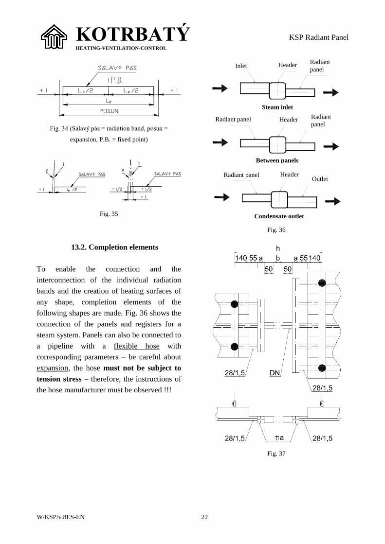
13.2. Completion elements
To enable the connection and the
interconnection of the individual radiation
bands and the creation of heating surfaces of
any shape, completion elements of the
following shapes are made. Fig. 36 shows the
connection of the panels and registers for a
steam system. Panels can also be connected to
a pipeline with a flexible hose with
corresponding parameters – be careful about
expansion, the hose must not be subject to
tension stress – therefore, the instructions of
the hose manufacturer must be observed !!!
Fig. 36
Fig. 37
Inlet Radiant
panel Header
Outlet
Header
Header
Radiant
panel Radiant panel
Radiant panel
Steam inlet
Between panels
Condensate outlet
KOTRBATÝ HEATING-VENTILATION-CONTROL
KSP Radiant Panel
W/KSP/v.8ES-EN 23
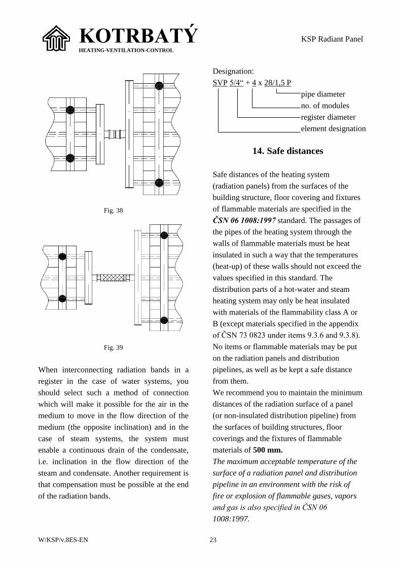
Fig. 38
Fig. 39
When interconnecting radiation bands in a
register in the case of water systems, you
should select such a method of connection
which will make it possible for the air in the
medium to move in the flow direction of the
medium (the opposite inclination) and in the
case of steam systems, the system must
enable a continuous drain of the condensate,
i.e. inclination in the flow direction of the
steam and condensate. Another requirement is
that compensation must be possible at the end
of the radiation bands.
Designation:
SVP 5/4“ + 4 x 28/1,5 P
pipe diameter
no. of modules
register diameter
element designation
14. Safe distances
Safe distances of the heating system
(radiation panels) from the surfaces of the
building structure, floor covering and fixtures
of flammable materials are specified in the
ČSN 06 1008:1997 standard. The passages of
the pipes of the heating system through the
walls of flammable materials must be heat
insulated in such a way that the temperatures
(heat-up) of these walls should not exceed the
values specified in this standard. The
distribution parts of a hot-water and steam
heating system may only be heat insulated
with materials of the flammability class A or
B (except materials specified in the appendix
of ČSN 73 0823 under items 9.3.6 and 9.3.8).
No items or flammable materials may be put
on the radiation panels and distribution
pipelines, as well as be kept a safe distance
from them.
We recommend you to maintain the minimum
distances of the radiation surface of a panel
(or non-insulated distribution pipeline) from
the surfaces of building structures, floor
coverings and the fixtures of flammable
materials of 500 mm.
The maximum acceptable temperature of the
surface of a radiation panel and distribution
pipeline in an environment with the risk of
fire or explosion of flammable gases, vapors
and gas is also specified in ČSN 06
1008:1997.
KOTRBATÝ HEATING-VENTILATION-CONTROL
KSP Radiant Panel
W/KSP/v.8ES-EN 24
15. Packing
The radiant panels are supplied on pallets
with the length of 6 m supported with
returnable square logs and packed in
shrinkage foil.
16. Disposal of the package and
product after the end of their
useful life
Waste must be sorted and handed over to an
organization involved in waste collection and
disposal. After the end of the life of the panel,
it must be dis-assembled and handed over for
recycling, while:
the panel is made of steel pipes,
the heating surface is made of aluminum
sheet.
Used packing Catalogue no.
Layered paper 15 01 01
Polyethylene foil 15 01 02
17. Transport
NOTE! The panels are supplied on
pallets with the maximum
length of 6 m.
During the transport, you must take measures
to prevent the panels from being damaged.
The manufacturer accepts no liability for
damages caused during transport, handling
and assembly.
18. Contact addresses
KOTRBATÝ V.M.Z. spol. s r.o.
ID: 49645955
Tax ID (VAT Nr.): CZ49645955
Design, consulting, service:
Služeb 5/256
108 00 Praha 10, Czech Republic
Tel., fax: +420 245 005 931
Production:
Sdružená 1788
393 01 Pelhřimov, Czech Republic
Tel., fax: +420 564 571 520, 30
KOTRBATÝ HEATING-VENTILATION-CONTROL
KSP Radiant Panel
W/KSP/v.8ES-EN 25
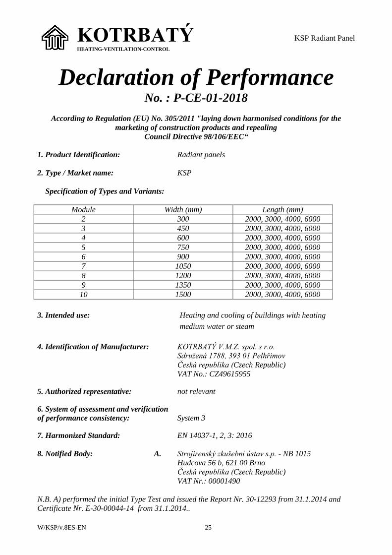
Declaration of Performance
No. : P-CE-01-2018
According to Regulation (EU) No. 305/2011 "laying down harmonised conditions for the
marketing of construction products and repealing
Council Directive 98/106/EEC“
1. Product Identification: Radiant panels
2. Type / Market name: KSP
Specification of Types and Variants:
Module Width (mm) Length (mm)
2 300 2000, 3000, 4000, 6000
3 450 2000, 3000, 4000, 6000
4 600 2000, 3000, 4000, 6000
5 750 2000, 3000, 4000, 6000
6 900 2000, 3000, 4000, 6000
7 1050 2000, 3000, 4000, 6000
8 1200 2000, 3000, 4000, 6000
9 1350 2000, 3000, 4000, 6000
10 1500 2000, 3000, 4000, 6000
3. Intended use: Heating and cooling of buildings with heating
medium water or steam
4. Identification of Manufacturer: KOTRBATÝ V.M.Z. spol. s r.o.
Sdružená 1788, 393 01 Pelhřimov
Česká republika (Czech Republic)
VAT No.: CZ49615955
5. Authorized representative: not relevant
6. System of assessment and verification
of performance consistency: System 3
7. Harmonized Standard: EN 14037-1, 2, 3: 2016
8. Notified Body: A. Strojírenský zkušební ústav s.p. - NB 1015
Hudcova 56 b, 621 00 Brno
Česká republika (Czech Republic)
VAT Nr.: 00001490
N.B. A) performed the initial Type Test and issued the Report Nr. 30-12293 from 31.1.2014 and
Certificate Nr. E-30-00044-14 from 31.1.2014..
KOTRBATÝ HEATING-VENTILATION-CONTROL
KSP Radiant Panel
W/KSP/v.8ES-EN 26
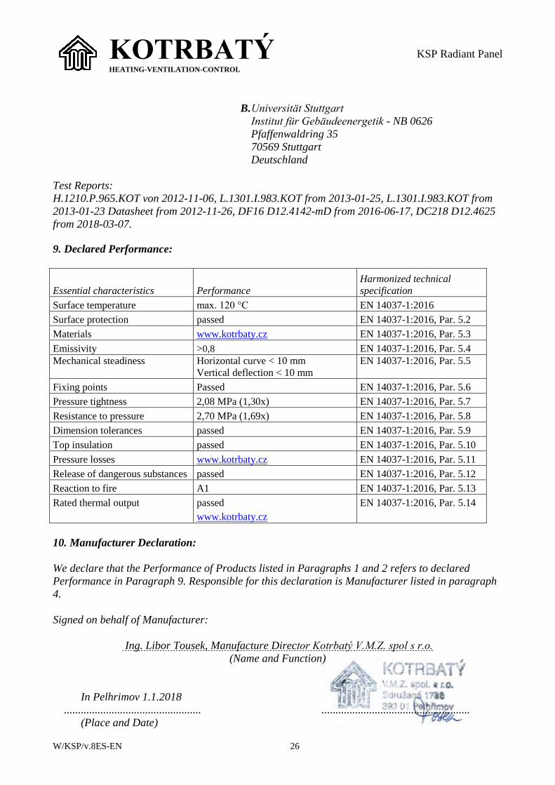
B. Universität Stuttgart
Institut für Gebäudeenergetik - NB 0626
Pfaffenwaldring 35
70569 Stuttgart
Deutschland
Test Reports:
H.1210.P.965.KOT von 2012-11-06, L.1301.I.983.KOT from 2013-01-25, L.1301.I.983.KOT from
2013-01-23 Datasheet from 2012-11-26, DF16 D12.4142-mD from 2016-06-17, DC218 D12.4625
from 2018-03-07.
9. Declared Performance:
Essential characteristics Performance
Harmonized technical
specification
Surface temperature max. 120 °C EN 14037-1:2016
Surface protection passed EN 14037-1:2016, Par. 5.2
Materials www.kotrbaty.cz EN 14037-1:2016, Par. 5.3
Emissivity >0,8 EN 14037-1:2016, Par. 5.4
Mechanical steadiness Horizontal curve < 10 mm
Vertical deflection < 10 mm
EN 14037-1:2016, Par. 5.5
Fixing points Passed EN 14037-1:2016, Par. 5.6
Pressure tightness 2,08 MPa (1,30x) EN 14037-1:2016, Par. 5.7
Resistance to pressure 2,70 MPa (1,69x) EN 14037-1:2016, Par. 5.8
Dimension tolerances passed EN 14037-1:2016, Par. 5.9
Top insulation passed EN 14037-1:2016, Par. 5.10
Pressure losses www.kotrbaty.cz EN 14037-1:2016, Par. 5.11
Release of dangerous substances passed EN 14037-1:2016, Par. 5.12
Reaction to fire A1 EN 14037-1:2016, Par. 5.13
Rated thermal output passed EN 14037-1:2016, Par. 5.14
www.kotrbaty.cz
10. Manufacturer Declaration:
We declare that the Performance of Products listed in Paragraphs 1 and 2 refers to declared
Performance in Paragraph 9. Responsible for this declaration is Manufacturer listed in paragraph
4.
Signed on behalf of Manufacturer:
Ing. Libor Tousek, Manufacture Director Kotrbatý V.M.Z. spol s r.o.
(Name and Function)
In Pelhrimov 1.1.2018
................................................. .....................................................
(Place and Date)