Embed Size (px)
Citation preview
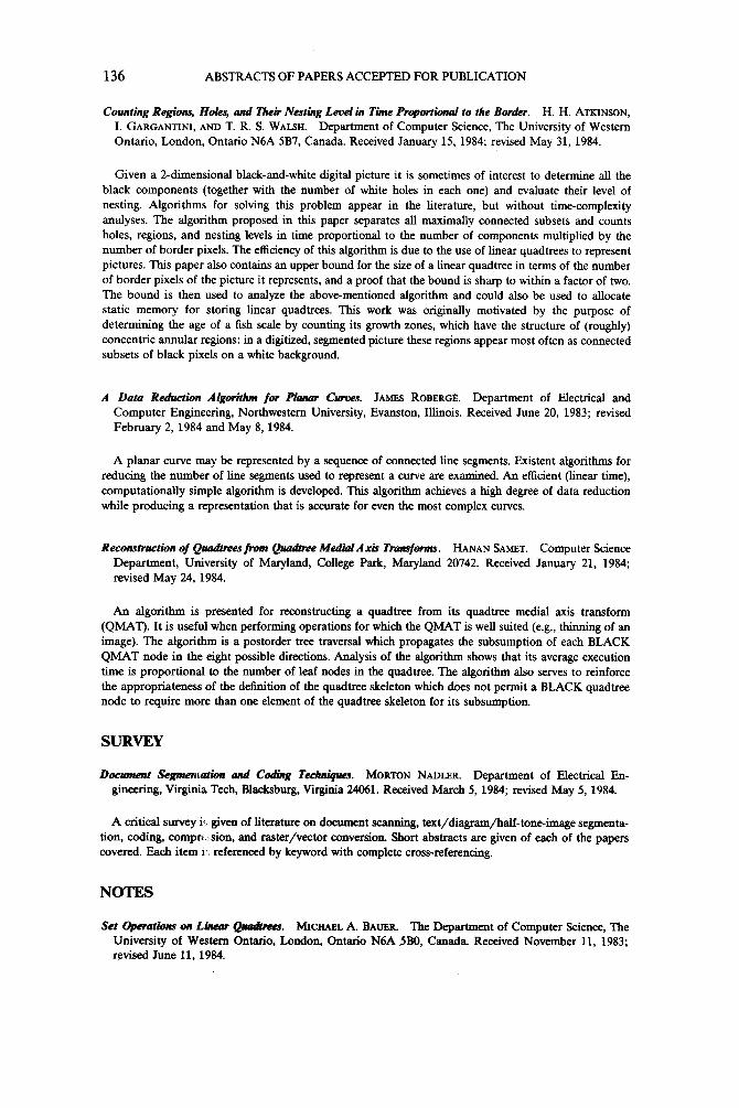
INT. COMM. HFATMASSTRANSFER 0735-1933/86 $3.00 + .00 Vol. 13, pp. 423-432, 1986 ~PergamonJournals Ltd. Printed in the United States
RADIANT-INTERCHANGE CONFIGURATION FACTORS INSIDE SEGMENTS OF FRUSTUM
ENCLOSURES OF RIGHT CIRCULAR CONES
Joseph C.Y. Wang Sui Lin Centre of Building Studies Mechanical Engineering Dept.
Concordia University, Montreal, Canada H3G IM8
Pai-Mow Lee School of Engineering
Lakehead University, Thunderbay, Canada P7B 5E8
Wei-Liang Dai You-Shi Lou Mechanical Engineering Dept. Department of Mathematics
Concordia University, Montreal, Canada H3G I M8
(C~q~tnicated by C.L. Tien)
ABSTRACT
Radiant-interchange configuration factors inside segments of frustum- enclosures of r ight circular cones are numerically determined and graphically presented.
Introduction
The solution of practical thermal radiation problems depends frequently
on the ava i lab i l i t y of interchange configuration factors. The interchange
configuation factors for many practical geometries have been presented [ i -6 ] .
The important groups of geometries which were not presented are the cases of
two segments cut from the two bases of a frustum-enclosure of r ight circular
cone by a plane parallel to the axis of the frustum-enclosure, and an
isosceles trapezoid and a segment of a disk being perpendicular to the
isosceles trapezoid and having a common edge with the isosceles trapezoid.
The purpose of this paper is to present the results of the configuration
factors for these two groups.
423

424 J.C.Y. Wang, et al. Vol. 13, No. 4
Determination of the Configuration factors
I t is well known that the conf igurat ion factor , FA~_A2, under the
assumption that the magnitude and surface distr ibut ion of the radiosity is
uniform over A~, can be expressed by
i [ [ cos 81c0s 62 dA1 dA2
= JA JA ( I ) FAI-A2 ~ I 2 xr2
where 61 and 62 are the angles formed by the normals of the elements dA1 and
dA 2 and the connecting l ine between the elements dAi and dA2. In Eq. (1) r
represents the length of the connecting l ine. I
Case 1. For the determination of the configuration factors for radiant inter-
change between two segments cut from the two bases of a frustum- enclosure of
r ight c ircular cone by a plane parallel to the axis of the frustum-enclosure,
a schematic diagram, Fig. 1, shows the coordinate syste, for the relat ive
position of the two segments. The contour of the segments Aland A 2 can be
expressed, respectively, by
y l = _+~a 2 - x~ (2)
The angles 61 and 62 can be obtained as d cos 61 = cos 62 = F (4)
where
r =~/(xl - x2) 2 + (Yl - Y2) 2 + d2 (5)
The areas of the elements dAi and dA2 can be expressed as
dAl = dxl dyi (6)
dA2 = dx2 dy2 (7)
and the total surface area of segment 1 is
= [cos- T - c 2 (8)
Substituting Eqs. (2) to (8) into Eq. (1) gives
FAI_A = ~ dx dx 2 dy i (9)
c Vb2_x~ ~ [ (xl-x2) 2+(yl-Y2) 2+d2 ] 2
Eq. (9) can be reduced to a double definite integration with constant lower
and upper l imi ts as

VOI. 13, NO. 4 RADIANT-INTERCHAN(~CGNFIGt~ATICN~RS 425
where
Y2 d2 [a b I [yl~n_1(~) . Y2~n.1(l(_) ] ~2
FAI"A2 = ~-~lJc dxl c ~ (1o)
X =~d 2 + (x I - x212 (111
Y1 x2 +V T. x2 (12) 1 2
Eq.
to 2.3.
FAI_A 2 ca lcu la ted for the case of a = b and c = -a (the two segments under
th is consideration become two disks having the same radius) was compared with
that obtained from the solution of radiant interchange between two bases of a
r igh t c i rcu lar cyl inder [1-6 ] . The comparison shows that both results agree
to 6 places of decimal for 1.0 < d/a < 100 while 5 places of decimal for
0.1 <_d/a < - l .
Case 2. For the determination of the configuration factors for an isosceles
trapezoid radiat ing to a segment of a disk being perpendicular to the
trapezoid and having a common edge with the trapezoid, Fig. 3 shows the
coordinate system for the re lat ive posit ion of the trapezoid and segment. The
contour of the segment can be described by
Y2 = + ~ + z l la - z) 1141
The contour of the legs of the isosceles trapezoid is
b 1 - b Yl = +- ( T X +~) (15)
The angles 1)i and f)2 can be written as _ z ( 1 6 ) c o s 111 - ?
Y2 = ~ - x2 - % / ~ - x2 (131 1 2
(10) was numerically integrated. The results ape shown in Figs. 2.1
In order to evaluate the accuracy of the numerical integrat ion,
x (17) cos P2 = ~ where
r =%/X 2 + (Yl - Y212 + z2 (18)
The areas of the elements dA1 and dA 2 ace expressed by
dA 1 = dx dy I (19)
dA2 = dY2 dz (20)

426 J.C.Y. Wang, et al. Vol. 13, No. 4
The total area of the trapezoid is
b I + b AI = (---Z--) • c (21)
Substituting Eqs. (14) to (21) into Eq. (1) gives
~b I - b ~/(b 2
FAI_A 2 = x-~-lJ'Co x dx[ zdz I dy I Jo b b I _ b J~j/(b 2 + r4
• / T X ~ ~T z)(a - z)
+ z)(a - z)
(22)
Eq. (22) can be reduced to a double definite integration with constant lower
and upper limits as
I I i Y2 Y3 Y~
1 c z (~)+Y2tan -I (~ ) Ystan -I (~r-)-Y4tan- I(~T-) ]dz FAI"A2=i~-'~-I o x dx ~-~-[3 Yltan-1 -
(23)
where
X =~/x 2 + z 2 (24)
b - b I +lu/( b2 Y1 = ( T x - ~) ~-~ + z)(a - z) (25)
Y2 = ( T x + ) - ~-~+ z)(a - z) (26)
. . . .
Y3 = ( ~ x - ) - ~-~+ z)(a - z) (27)
Y4 : (---Z~---x + ) (T~ + z)(a - z) (28)
The double definite integration of Eq. (23), with constant lower and upper
l imits, was numerically calculated. The results are shown in Figs. 4.1 to
4.4.
I t should be noted that there is a singularity existing in the evaluation
of Eq. (23) at x = z = 0. To accomplish the integration of Eq. (23), the
lower l imi ts of x and z in the integration are modified to very small values
instead of zeros. The modified lower l imits are so chosen that i t gives
s a t i s f a c t o r y accuracy to the value of FAI_A 2. Results indicate that a
modified lower l im i t having a value of 10 -8 w i l l give a good accuracy for
FA1-A2"

Vol. 13, No. 4 RADIANT-INTER2HANGE CC~FI(~RATICN F~I~ORS 427
Appl icat i on Example
As an example, we consider the case that a frustum-enclosure of r ight
c i rcular cone be cut by a plane parallel to the axis of the frustum-enclosure
as shown in Fig. 5. By making use of the configuration factors presented in
Figs. 2.1 to 2.3 and 4.1 to 4.4, and in combination with the configuration
factors for radiation interchange between a disk and a segment of a parallel
concentric disks [7], the configuration factors for radiation interchange
between any two of the ten surfaces (surfaces 1,2,3,4,5, 6,7,(1+2),(3+4),
(5+6)) as shown in Fig. 5, can be determined.
References
1. R. Siegel, J.R. and Howell, "Thermal Radiation Heat Transfer", 2nd. Ed.
McGraw-Hill, New York (1981).
2. E.M. Sparrow and R.D. Cess, "Radiation Heat Transfer", McGraw-Hill, New
York (1978).
3. H.C. Hottel and A.F. Sarofim, "Radiative Transfer", McGraw-Hill, New York
(1967).
4. H.Y. Wong, "Handbook of Essential Formulae and Data on Heat Transfer for
Engineers", Longman, New York (1977).
5. J.A. Stevenson and J.C. Grafton, "Radiation Heat Transfer Analysis for
Space Vehicles", SID 61-91, North ~erican Aviation, (ASD TR 61-119, pt.
1), (Dec. 1961).
6. J.R. Howell, "A Catalogue of Radiation Configuration Factors", pp.
89-242, McGraw-Hill, New York (1982).
7. S. Lin, P.M. Lee, J.C.Y. Wang, W.L. Dai and Y.S. Lou, "Radiant-lnterchange
Configuration Factors between a Disk and a Segment of a Parallel
Concentric Disk", Int. J. Heat Mass Transfer (in press).

428 J.C.Y. Wang, et al. Vol. 13, No. 4
z dA 2
b (x2 Y2'd) X2
4o/
A1 o
(xI,Yl,O)
FIG.1 Geometric configuration for radiant interchange between two segments cut from the two bases of a frustum enclosure of right circular cone by a plane parallel to the axis of the frustum enclosure.
F A I-A2
I
c/a-O.O
0.0- oo
0 , 4 - -
0.3-
0.2--
0.1-
0 . 0 -
10-2 v I vo d/a FIG.2.1
FIG.2.1--2.3 Configuration factors, F A -A ' for radiant interchange between
two segments cut from the two bases of ~ f~ustum enclosure of right circular cone by a plane parallel to the axis of the frustum enclosure as a function of d/a with b/a as a parameter. FIG.2.1 for c/a=O.O, FIG.2.2 for c/a-0.5, FIG.2.3 for c/a=0.99.

VOl. 13, NO. 4 RADIANT-~CC~I(~RATICNF2~S 429
FA I-A2
1
B.
~o
B . B -
1 g - 2
~ .,~, ~/.-o.s
\
~~ ~/-~.,oo \\\\\"~,~
, \\~\
I g - I I I ~ FIG.2.2
d/a
F A i-A2
1 .~--
g.8 =
~ .7~
~.6 =
~.5--
~ . 4 -
z. 2-:"
~.I~
Ig-2 I I I I I I I
10-I
[ b / a - I00
×\ \ \ \ \
I~ 2 d/a I I l l l l
FIG.2.3
c /a -0 .99
10

430 J.C.Y. Wang, et al. Vol. 13, No. 4
J -dA 1
(x,Yl,0)
FIG.3 Geometric configuration for an isosceles trapezoid radiating to a segment of a disk being perpendicular to the trapezoid and having a common edge with the trapezoid.
I" A I - A 2
O.
O, ~ ~ ~ b |Ib=O.O
0 .
2:2 10 I I 10 | 0 2 c/b
FIG.4.1 FIG.4 .1 - -4 .4 Conf igurat ion f a c t o r s , F A A ' for r a d i a n t in terchange between
an isosceles trapezoid and a segment ofla ~isk being perpendicular to the trapezoid and having a common edge with the trapezoid as a function of c/b with a/b as a parameter. FIG.4.1 for bl/b:O.O, FIG.4.2 for bl/b=O.5, FIG.4.3 for b l /b=l .O, FIG.4.4 for bl/I~=2.0

Vol. 13, NO. 4 RADIANT-INT~RCHAN(~ CONFI(~JRATION FACIDRS 431
F' A I-A2
\ \ \ \ \ \
i:iii \ \;\~'
1 0 ~-I
FA l-A2
1 10 !
FIG.4.2
0 .
0 .
0 .
0 .
0 .
0 . 1
0 . 1
0 . 0 0 -
10
~ bllb=l'O
\\'~ \\\\\\ ~o
, ) \ \ \ ~ \ \ \ \
\\\\ \I \\\\\ \
clb
FIG.4.3 I 1 0 c/b

432
F A I-A2
0.
0 . 2 5 -
0 . 2 0 -
O.1
O.1
0,
0.00
10 -I
J.C.Y. Wang, et al. Vol. 13, No. 4
, \ \ L. ~ ~ ~ X. XIX XXX
1 1 0 clb
FIG.4.4
1 2
5 6
FIG.5 Geometric configuration for the application example --- determination of configuration factors for radiant interchange between any two of the ten surfaces. ( l , 2, 3, 4, 5, 6, 7, (I+2), (3+4), (5+6)).