Embed Size (px)
Citation preview

Research Article
2166
Received: 30 January 2010, Revised: 29 March 2010, Accepted: 6 April 2010, Published online in Wiley Online Library: 30 July 2010
(wileyonlinelibrary.com) DOI: 10.1002/pat.1740
Radar transparent glass fabric reinforcedpolyetherimide/Cloisite 30B nanocomposites
Mayank Dwivedia,d*, Sarfaraz Alamb, Naresh Bhatnagarc
and Anup K. Ghoshd
High performance radar transparent materials (RT
Polym. Adv
Ms) are important materials for the fabrication of radomes,nosecones, etc. of high velocity aerospace vehicles. RTMs with good mechanical performance and temperaturecapability are required for such applications. Toward this, fabric reinforced nano-reinforced matrix composites(FRNCs), using reinforcing E-glass fabric in Cloisite 30B reinforced polyetherimide (PEI) nanocomposite matrix(GNRPEI), was prepared. The properties of GNRPEI were evaluated and compared with E-glass fabric reinforcedPEI composites (GRPEI) with special reference to their radar transparent character for aerospace applications. Tensileand flexural properties along with interlaminar shear strength of GRPEI were observed to be lower than those ofGNRPEI. Thermal behavior of both the composites was similar in differential scanning calorimetry and thermalgravimetric analysis. But, in dynamicmechanical analysis, an increase in storagemodulus and decrease in loss tangentwere observed in GNRPEI compared to GRPEI. The values of dielectric constant and loss tangent of GNRPEI were lesserthan those of GRPEI, but no significant difference was observed in the values of transmission and reflection losses forboth the composites at 8–12GHz frequency. FRNCs, based on organoclay reinforced PEI matrix, hold good promise ashigh performance RTMs. Copyright � 2010 John Wiley & Sons, Ltd.
Keywords: aerospace; high performance; polyetherimide; polymeric nanocomposites; radar transparent materials
* Correspondence to: M. Dwivedi, Defence R&D Organisation, Defence R&D 404,DRDO Bhawan, Rajaji Marg, New Delhi 110105, Delhi, India.E-mail: [email protected]
a M. Dwivedi
Defence R&D Organisation, Defence R&D 404, DRDO Bhawan, Rajaji Marg,
New Delhi 110105, Delhi, India
Centre for Polymer Science and Engineering, Indian Institute of Technology,
New Delhi, Delhi, India
b S. Alam
Polymer Science Division, Defence Materials and Stores Research and
Development Establishment, Kanpur, India
c N. Bhatnagar
Department of Mechanical Engineering, Indian Institute of Technology, Delhi,
New Delhi, India
d M. Dwivedi, A. K. Ghosh
Centre for Polymer Science and Engineering, Indian Institute of Technology,
New Delhi, Delhi, India
INTRODUCTION
Transparency to electromagnetic (EM) radiation coupled withgood mechanical properties and thermal stability are theimportant factors for radar transparent aerospace structures.The service conditions are grossly dependent on the operationalenvironment, which consists of wind, moisture, and temperature.Polymer nanocomposites provide significantly increasedmodulus, gas barrier, thermal performance, atomic oxygenresistance, resistance to small molecule permeation, andimproved ablative performance when compared to typicaltraditional fiber-reinforced polymeric composites.[1,2] The pio-neering work in polymeric nanocomposites was done by ToyotaCentral Research and Development Laboratories, Inc. and the firstmontmorillonite reinforced polyamide (PA) 6 nanocomposite wasdeveloped by them in late 1980s.[3] It showed an increase of103% in Young’s modulus, 49% increase in tensile strength and146% increase in heat distortion temperature over pristine PA 6.[4]
Other properties such as fire retardancy[5,6] and barrier proper-ties[7,8] also showed an improvement. The reinforcement oforganoclays in polymers, at 1–1.5wt% loading, optimizes themechanical performance of the resultant nanocomposites.[9]
The reinforcement of nanoclay in polymer matrix may not beable to provide the required mechanical strength for theairframes of high velocity aerospace vehicles. At this point,further reinforcement of continuous microfiber such as glassfibers, Kevlar fibers, etc. might be needed to strengthen thestructure. Such composites might be called fabric reinforcednano-reinforced matrix composites (FRNCs). It has been reportedthat PA 6/nanoclav matrix reinforced with glass fibers wassuperior to PA 6/glass fiber composites.[10] Short or long glass
. Technol. 2011, 22 2166–2172 Copyright
fiber reinforced PA 6/nanoclav composites have goodmechanicaland barrier properties along with moisture resistance.[11]
The aim of this study was to develop a composite for theapplications in high velocity radar transparent aerospacestructures. Toward this, a FRNC, which had reinforcement of E-glass fabric in 1% Cloisite 30B reinforced polyetherimide (PEI)matrix (GNRPEI), was developed. The mechanical, thermal,viscoelastic, and electromagnetic responses of GNRPEI wereevaluated and compared with E-glass fabric reinforced PEI(GRPEI) along with establishing the processing parameters forthese composites.
� 2010 John Wiley & Sons, Ltd.

Figure 1. Molding cycle.
GLASS/POLYETHERIMIDE/CLOISITE 30B NANOCOMPOSITES
2
EXPERIMENTAL
The experiments were designed to first fabricate GNRPEI andGRPEI composites and then evaluate and compare theirmechanical, thermal, viscoelastic, and electromagnetic perform-ances.
Materials
Polymeric nanocomposite (PNC) matrix
Processing of nanoclay reinforced PEI nanocomposites hasalready been reported by in situ polymerization and meltprocessing.[12–14] PEI (Grade: Ultem 1000) and Cloisite 30B (whichhas surfactant methyl tallow bis-2-hydroxyethyl ammonium)were procured from GE Plastics, USA and Southern Clay Products,USA, respectively. In this study, the PEI films and Cloisite 30Breinforced PEI films were prepared by casting process, using 0.5,1, 2, and 3wt% Cloisite 30B; the nomenclature used for these isPNC0.5, PNC1, PNC2, and PNC3, respectively.
Teflon coated glass fabric
Teflon coated glass fabric of thickness 0.12mm was used as peelply for easy release of themolding from themold. It was procuredfrom M/s Unnati Corporation, Ahmedabad, India.
Characterization of PEI and PNC1 films
Tensile testing
PEI and PNC films were tested for tensile strength, modulus andelongation at break as per ASTM 882 method on a Star TestingSystem model 945 Universal Testing Machine at a crossheadspeed of 5mm/min.
Thermal analysis
Differential scanning calorimetry (DSC) on a TA Instrumentsmodel Q 200 was carried out for PEI, PNC1 and GNRPEI and GRPEIas per ASTM D3418. Thermo gravimetric analysis (TGA) on aMettler Toledo model SF 1100 with SDTA-815e was carried out forPEI and PNC1, and on a Perkin Elmer model Pyris 6TGA wascarried out for GNRPEI and GRPEI as per ASTM D3418. DSC andTGA were carried out up to 400 and 9008C, respectively, at aheating rate of 10 8C/min. These samples were prepared bycutting the samples in small sizes, in the weight range of 5–7mg,by hand operated shearing equipment.
Electromagnetic performance
Dielectric constant and loss tangent were carried out on a Agilentmodel 85070E dielectric probe kit and evaluation of transmissionloss was carried out on a Agilent model 85071E microwavebench at 8–12GHz frequency.[15] The sample size was22.9� 10.2� 0.2mm3.
Transmission electron microscopy (TEM)
A Philips model Tecnai F30 TEM was used on PNC1 nanocompo-sites to examine the detailed morphology. The samples weresectioned to 50–70 nm with a diamond knife using Leica UltracutUCT microtome. The sections were collected on 300 meshcarbon-coated copper grids from water boat and dried on filterpaper.
Polym. Adv. Technol. 2011, 22 2166–2172 Copyright � 2010 Joh
Wide angle X-ray diffraction (WAXD)
WAXD analysis of Cloisite 30B and PNC1 samples was carried outusing a Rigaku Dmax 2500 unit.
E-glass fabric
4-harness satin weave E-glass fabric of thickness 0.33mm withareal density of 425� 25 GSMwas used. It was procured fromM/sUnnati Corporation, Ahmedabad, India. The E- glass fabric isreferred to as glass fabric.
Molding of composite laminates
The GNRPEI and GRPEI composites were made in a matched diemold having cavity dimension of 150� 120� 3mm3. The moldwas cleaned with acetone and, later, silicone release agent wassprayed on its surfaces. The lay up sequence was designed byplacing eight alternate layers of PNC1 film and glass fabric forGNRPEI composite and similarly, eight alternate layers of PEI filmand glass fabric were placed for GRPEI composite. The thicknessof each layer of PNC1 or PEI film was approximately 200mm. Thefilm was cut into small pieces of 2–4 cm2 at the time of placementof layer so that no air is entrapped within the composite laminateduring molding. The placement was made in such a way thatboth top and bottom layers were of PNC1 film for GNRPEI and PEIfilm for GRPEI composites, so that the composite laminates weremasked by matrix. Only eight layers of glass fabric were placed insuch a way that all the warp direction yarns of the fabric wereplaced in the longitudinal direction. Teflon coated glass fabricwas placed on the top and bottom surfaces of the dry stack forbetter release of the molding.GNRPEI and GRPEI composites were compression molded
using a Carver Auto Series compression-molding machine. Amolding cycle was developed to carry out the compressionmolding of these laminates. The platens of the compression-molding machine were preheated to 2008C. The matched diemold was placed between the heated platens and then contactpressure was applied. The maximum temperature and load onthe mold were kept at 2908C and 6 ton, respectively. The heatingrate was maintained at 108C/min. The molding was carried out asper the molding cycle mentioned in Fig. 1.The mold was allowed to cool naturally, by switching off the
heating system, before it was taken out from the compression-molding machine. The molding, along with the layers of Tefloncoated glass fabric, was removed easily after removing little flashalong the periphery of the spacer plate. The edges of themoldingwere trimmed with a power sander and Teflon coated glass fabric
n Wiley & Sons, Ltd. wileyonlinelibrary.com/journal/pat
167

M. DWIVEDI ET AL.
2168
was peeled off from the composite laminate. The test sampleswere prepared using the electrical circular cutting saw.
Characterization of GNRPEI and GRPEI composites
Specific gravity and void content
Specific gravity and void content were measured as per the ASTMD792A and ASTM D2734 methods, respectively.
Ultrasonic through transmission test
Ultrasonic flaw detection test was carried out on a Sonar Test310 B as per ASTM E2580 standard. The test was carried out at20 dB energy of ultrasonic wave; the dry contact method, withrubber probes, was used.
Evaluation of constituent content
This test was carried out as per ASTM D3171 standard. In thismethod, small pieces of samples of known weight were placed incrucibles and heated in a Toshniwal Industries furnace at 6508Cfor 6 hr. The crucibles were then cooled to room temperature andresidual glass fiber was weighed and its weight % was calculated.
Hardness
Rockwell hardness of all specimens was tested on a BuehlerMACROMET I Rockwell hardness tester as per ASTM D785.
Tensile, flexural, and interlaminar shear stress (ILSS) tests
These tests were carried out on a Zwick model Z010 UniversalTesting Machine. Ultimate tensile strength, ultimate tensile strain,modulus of elasticity, and elongation at break in the test directionwere tested as per ASTM D3039 at cross head speed of 2mm/minand grip distance of 100mm. Flexural strength andmodulus weretested as per ASTM 749D at cross head speed of 5mm/min andspan length of 60mm. ILSS was tested as per ASTM D2344 atcross head speed of 5mm/min and span length of 40mm. ILSSsamples were cut in such a way that the orientation of warp andweft yarns of glass fabric were at�458 from longitudinal axis. Themeasurement of ILSS of layered silicates filled glass fiberreinforced PA 6 laminate, at ply angle of �458, has beenreported.[16]
Impact strength
Notched impact strength of the samples was measured as perASTM D256 on a ats Faar model Impat-15 pendulum type impacttester.
Table 1. Properties of PEI and PEI/Cloisite 30B composites
S. no. Property Unit
1 Wt. of Cloisite 30B in PEI %2 Glass transition temperature 8C3 TGA weight loss at 5908C %4 Tensile strength MPa5 Tensile modulus MPa6 Elongation at break %7 Dielectric constant (at 8–12GHz) —8 Loss tangent (at 8–12GHz) —9 Transmission loss (at 8–12 GHz) dB
wileyonlinelibrary.com/journal/pat Copyright � 2010 John
Dynamic mechanical analysis (DMA)
DMA provides the viscoelastic response of the samples. DMA on aTA instruments model Q 800 was carried out at heating rate of58C/min and 1Hz frequency in nitrogen atmosphere. The test wascarried out up to 3008C.
Dielectric constant (e’), loss tangent (tan d), transmission loss, andreflection loss
Dielectric constant and loss tangent were measured on a Agilentmodel 85070E dielectric probe kit. Transmission loss andreflection loss were measured on a Agilent 85071E microwavebench.[15] The sample size was 22.9� 10.2� 3.0mm3. Thesamples were tested in the frequency range of 8–12GHz(X-Band) at room temperature.
RESULTS AND DISCUSSION
PEI and PNC films
Tensile, thermal, and electromagnetic performance
The values of tensile, thermal and electromagnic responses of PEIand PNC films are tabulated in Table 1.It has been observed that PNC1 has the best properties among
all PNCs. The reason for good mechanical properties of PNC1 wasattributed to the optimum reinforcement of Cloisite 30B in PEImatrix and also, to the formation of hydrogen bond betweenhydroxyl groups of Cloisite 30B and ether group of PEI. Theformation of hydrogen bond between hydroxyl groups of Cloisite30B and carbonyl group of matrix has been reported.[16] The glasstransition temperature and weight loss were similar for all thecompositions under the analysis. The values of dielectric constantand transmission loss for all the samples were also similar. Thevalues of loss tangent were the least for PNC1, PNC2, and PNC3among all the samples under this analysis. The reason for thismay be attributed to uniform dispersion and no adverse effect ofCloisite 30B on electromagnetic performance while it hasmarginally reduced the loss tangent.
Morphology of PNC1 matrix
The WAXD graphs for Cloisite 30B and PNC1 are shown at Fig. 2where it could be seen that their peaks occurred at 2u value ofapproximately 4.98 (Fig. 2a) and 4.48 (Fig. 2b), respectively. Thedecrease in value of 2u of PNC1 over Cloisite 30B was attributedto increased d-spacing due to intercalation. The intensity of PNC1
PEI PNC 0.5 PNC1 PNC2 PNC3
0 0.5 1 2 3216 218 218 218 21741 42 41 42 4372.4 82.8 95.9 74.3 64.81309 1753 2236 1887 16556.6 5.5 5.0 4.5 4.43.4 3.7 3.8 3.8 3.80.05 0.06 0.03 0.02 0.02�0.2 �0.2 �0.2 �0.2 �0.2
Wiley & Sons, Ltd. Polym. Adv. Technol. 2011, 22 2166–2172
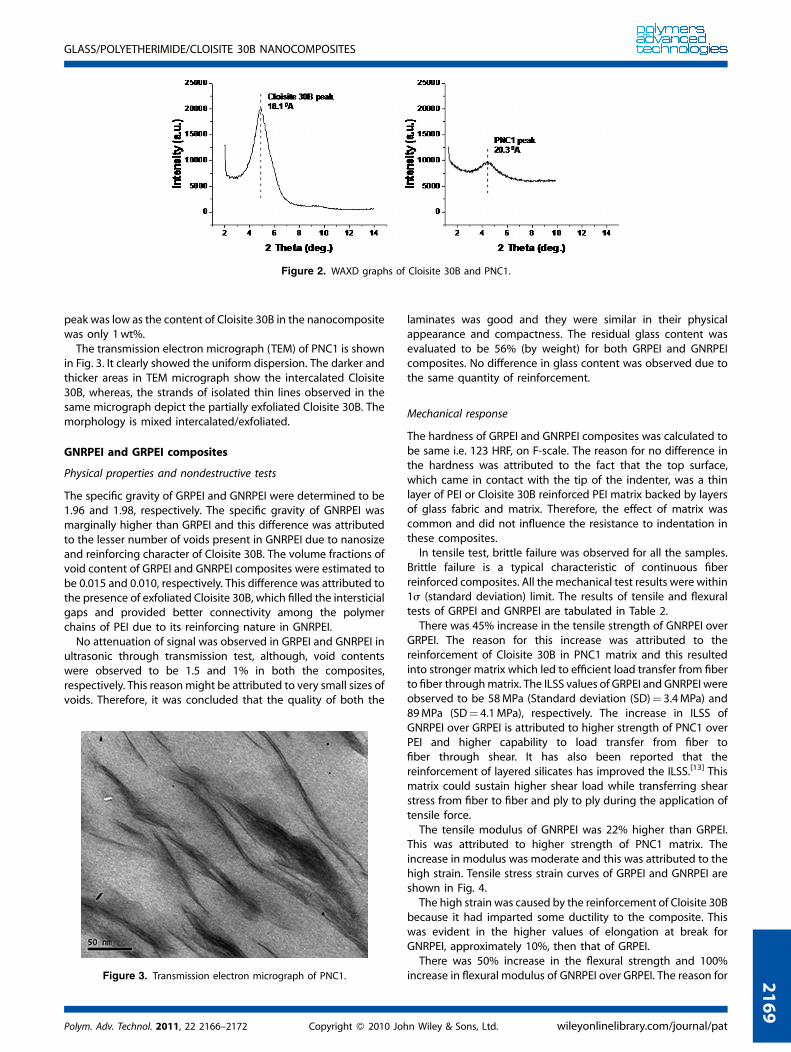
Figure 2. WAXD graphs of Cloisite 30B and PNC1.
GLASS/POLYETHERIMIDE/CLOISITE 30B NANOCOMPOSITES
peak was low as the content of Cloisite 30B in the nanocompositewas only 1wt%.The transmission electron micrograph (TEM) of PNC1 is shown
in Fig. 3. It clearly showed the uniform dispersion. The darker andthicker areas in TEM micrograph show the intercalated Cloisite30B, whereas, the strands of isolated thin lines observed in thesame micrograph depict the partially exfoliated Cloisite 30B. Themorphology is mixed intercalated/exfoliated.
GNRPEI and GRPEI composites
Physical properties and nondestructive tests
The specific gravity of GRPEI and GNRPEI were determined to be1.96 and 1.98, respectively. The specific gravity of GNRPEI wasmarginally higher than GRPEI and this difference was attributedto the lesser number of voids present in GNRPEI due to nanosizeand reinforcing character of Cloisite 30B. The volume fractions ofvoid content of GRPEI and GNRPEI composites were estimated tobe 0.015 and 0.010, respectively. This difference was attributed tothe presence of exfoliated Cloisite 30B, which filled the intersticialgaps and provided better connectivity among the polymerchains of PEI due to its reinforcing nature in GNRPEI.No attenuation of signal was observed in GRPEI and GNRPEI in
ultrasonic through transmission test, although, void contentswere observed to be 1.5 and 1% in both the composites,respectively. This reasonmight be attributed to very small sizes ofvoids. Therefore, it was concluded that the quality of both the
Figure 3. Transmission electron micrograph of PNC1.
Polym. Adv. Technol. 2011, 22 2166–2172 Copyright � 2010 Joh
2
laminates was good and they were similar in their physicalappearance and compactness. The residual glass content wasevaluated to be 56% (by weight) for both GRPEI and GNRPEIcomposites. No difference in glass content was observed due tothe same quantity of reinforcement.
Mechanical response
The hardness of GRPEI and GNRPEI composites was calculated tobe same i.e. 123 HRF, on F-scale. The reason for no difference inthe hardness was attributed to the fact that the top surface,which came in contact with the tip of the indenter, was a thinlayer of PEI or Cloisite 30B reinforced PEI matrix backed by layersof glass fabric and matrix. Therefore, the effect of matrix wascommon and did not influence the resistance to indentation inthese composites.In tensile test, brittle failure was observed for all the samples.
Brittle failure is a typical characteristic of continuous fiberreinforced composites. All themechanical test results were within1s (standard deviation) limit. The results of tensile and flexuraltests of GRPEI and GNRPEI are tabulated in Table 2.There was 45% increase in the tensile strength of GNRPEI over
GRPEI. The reason for this increase was attributed to thereinforcement of Cloisite 30B in PNC1 matrix and this resultedinto stronger matrix which led to efficient load transfer from fiberto fiber throughmatrix. The ILSS values of GRPEI and GNRPEI wereobserved to be 58MPa (Standard deviation (SD)¼ 3.4MPa) and89MPa (SD¼ 4.1MPa), respectively. The increase in ILSS ofGNRPEI over GRPEI is attributed to higher strength of PNC1 overPEI and higher capability to load transfer from fiber tofiber through shear. It has also been reported that thereinforcement of layered silicates has improved the ILSS.[13] Thismatrix could sustain higher shear load while transferring shearstress from fiber to fiber and ply to ply during the application oftensile force.The tensile modulus of GNRPEI was 22% higher than GRPEI.
This was attributed to higher strength of PNC1 matrix. Theincrease in modulus was moderate and this was attributed to thehigh strain. Tensile stress strain curves of GRPEI and GNRPEI areshown in Fig. 4.The high strain was caused by the reinforcement of Cloisite 30B
because it had imparted some ductility to the composite. Thiswas evident in the higher values of elongation at break forGNRPEI, approximately 10%, then that of GRPEI.There was 50% increase in the flexural strength and 100%
increase in flexural modulus of GNRPEI over GRPEI. The reason for
n Wiley & Sons, Ltd. wileyonlinelibrary.com/journal/pat
169

Table 2. Tensile and flexural properties of GRPEI and GNRPEI composites
S. no. Property Unit GRPEI GNRPEI
1 Tensile strength MPa 199 (SD¼ 10) 292 (SD¼ 16)2 Tensile modulus MPa 3200 (SD¼ 36) 3900 (SD¼ 245)3 Elongation at break % 8.2 9.04 Flexural strength MPa 227 (SD¼ 14) 340 (SD¼ 18)5 Flexural modulus MPa 7000 (SD¼ 317) 14000 (SD¼ 895)6 Deflection at fracture in flexural mode % 3.7 2.8
SD- Standard deviation.
M. DWIVEDI ET AL.
2170
this increase was attributed to the reinforcement of Cloisite 30B inPNC1 matrix which resulted in a strong matrix. In flexural test, thebottom portion of sample below the neutral axis is under tensionand upper portion is under compression. In the case of GRPEIcomposites, the glass fibers, which are aligned in the direction ofthe load under tension, bear the maximum load but undercompression, the same glass fibers get squeezed or wrinkled inthe direction of compressive force, and, therefore, do not play amajor role in bearing the compressive load. On the contrary,wrinkling or squeezing of glass fibers did cause the debonding ordelamination within the composites. Whereas, in the case ofGNRPEI, intercalated and exfoliated Cloisite 30B acted asreinforced platelets (similar to particulate reinforcement), thus,causing an increase in compressive load bearing capability. It hasbeen reported that the reinforcement of layered silicates hasimproved the flexural properties.[17] The impact energy was295 J/m (SD¼ 8 J/m) and 640 J/m (SD¼ 15 J/m) for GRPEI andGNRPEI, respectively. Higher impact energy of GNRPEI over GRPEIis attributed to reinforcement of Cloisite 30B which makes thePNC1 matrix more ductile.
Thermal analysis
DSC scan for GRPEI and GNRPEI composites are shown in Fig. 5.Glass transition temperatures (Tg), quantity of heat flow and
temperature of melting peaks of GRPEI and GNRPEI compositeswere similar and these values are given in Table 3. The �28Ctolerance in various transitions in DSC is within experimentallimits, so there is no effect here.Tg, temperatures of melting peaks and values of the heat flow
for both the composites are similar and reinforcement of Cloisite30B neither affected the translational motion among the
Figure 4. Tensile stress strain curves of GRPEI and GNRPEI composites.
wileyonlinelibrary.com/journal/pat Copyright � 2010 John
polymeric chains nor the melting of PEI matrix. The samebehavior was observed for PNC matrices mentioned in Table 1.There was no difference observed in onset (The point obtained
by intersecting the tangents on shoulder region which occurswhen the weight loss starts) and end set (the point obtained byintersecting the tangents on shoulder region which occurs whenweight loss stops) temperatures of weight loss in TGA traces ofGRPEI and GNRPEI. The results of TGA (on set temperature ofweight loss, end set temperature of weight loss and char yield)and DMA (glass transition temperature, storage modulus, lossmodulus and loss tangent), for GRPEI and GNRPEI, have beentabulated in Table 3. The values are the same, considering the�1% tolerance in char yield in TGA and�28C tolerance in variousthermal transitions of DMA. An increase of 2% was observed inthe char yield of GNRPEI over GRPEI in TGA; part of this char yieldmight be attributed to the presence of residual Cloisite 30B.In DMA, Tg of GNRPEI and GRPEI was observed at 2208C. Values
of Tg in DMA are higher than the values obtained from DSC, dueto the mechanical stresses. As was also seen in DSC, there is noeffect on Tg due to presence of nanoclay. Storage modulus andloss modulus of GNRPEI composite were higher than that ofGRPEI composite. This is attributed to the reinforcement ofCloisite 30B and the strong interphase between glass and PNC1matrix. The reinforcement of Cloisite 30B led to the enhancementin the values of storage modulus and loss modulus. This isattributed to higher tensile modulus of PNC1 than PEI (Table 1).The reinforcement of Cloisite 30B caused the restriction in themovement of polymeric chains, hence the reduction in the strainand, thus, the storage modulus increased significantly. The losstangent of GNRPEI composite was lower than that of GRPEIcomposite because the storage modulus of GNRPEI compositewas much higher than that of GRPEI, therefore, the ratio of loss
Figure 5. DSC scan for GRPEI and GNRPEI composites.
Wiley & Sons, Ltd. Polym. Adv. Technol. 2011, 22 2166–2172

Table 3. Results of DSC, TGA, and DMA for GRPEI and GNRPEI composites
S. no. Property Unit GRPEI GNRPEI
1 Glass transition temperature (DSC) 8C 215 2172 Temperature of melting peak 8C 222 2233 Heat flow (DH) J/g 2.3 2.14 On set temperature of weight loss 8C 532 5325 End set temperature of weight loss 8C 585 5846 Char yield % 25.7 27.67 Glass transition temperature (DMA) 8C 220 2208 Storage modulus (Max) MPa 3450 53509 Loss modulus (Max) MPa 610 105010 Loss tangent (Max) — 0.8 0.6
GLASS/POLYETHERIMIDE/CLOISITE 30B NANOCOMPOSITES
modulus to storage modulus remained lower. The lower lossmodulus of GNRPEI would lead to its better performance in actualapplication as composite structures. Typical DMA curve forGNRPEI is shown in Fig. 6.
Electromagnetic performance
The values of dielectric constant, loss tangent, transmission loss,and reflection loss of GRPEI and GNRPEI composites are tabulatedat Table 4.The dielectric constants and loss tangents of GNRPEI and GRPEI
were found to be quite close. It might be concluded that theeffect of Cloisite 30B on dielectric constant and loss tangent ofGNRPEI was negligible. Similarly, a negligible difference intransmission and reflection losses of GNRPEI and GRPEI wasobserved as tabulated in Table 4. This indicated that thereinforcement of Cloisite 30B did not adversely affect thetransmission of reflection properties of GNRPEI. Ideally, thereshould be no loss of signal, in transmission or reflection mode, forthe best performance of any radar transparent structure. For thematerials having similar dielectric constant and loss tangent,
Figure 6. Typical DMA curv
Polym. Adv. Technol. 2011, 22 2166–2172 Copyright � 2010 Joh
the transmission and reflection losses are also similar. Therefore,the results of transmission and reflection losses corroborate theresults of dielectric constant and loss tangent of GNRPEI andGRPEI.
STRUCTURE PROPERTY RELATIONSHIP INFRNC
The matrix for GNRPEI was PNC1 which contained intercalatedand exfoliated Cloisite 30B. The intercalated and exfoliatedCloisite 30B played a major role in overall properties of theGNRPEI. The schematic of layer structure of GNRPEI is shown inFig. 7. Figure 7(a) represents the dry stack of GNRPEI beforemolding. Figure 7(b) represents the distribution of Cloisite 30B,after compression molding, in horizontal and vertical directionsacross the layers through the interstices present in the fiberbundles of glass yarns. Cloisite 30B is present in both the forms,i.e. exfoliated as well as intercalated, in the gaps between theyarn of the fabric and is helpful in transferring the loadbetween fibers through shear. It filled the voids, thereby, resulting
e for GNRPEI composites.
n Wiley & Sons, Ltd. wileyonlinelibrary.com/journal/pat
2171

Table 4. Values of dielectric constant, loss tangent,transmission loss and reflection loss of GRPEI and GNRPEIcomposites at 8–12GHz frequency
S. no. Property Unit GRPEI GNRPEI
1 Dielectric constant — 3.8 3.62 Loss tangent — 0.010 0.0123 Transmission loss dB �3.6/�2.6 �3.5/�2.54 Reflection loss dB �4.1/�2.7 �3.6/�2.7
Figure 7. Schematic representation of GNRPEI (a) dry stack before
molding and (b) distribution of Cloisite 30B after compression molding.This figure is available in color online at wileyonlinelibrary.com/journal/
pat
M. DWIVEDI ET AL.
2172
in a good structural FRNC. The exfoliation of Cloisite 30Bprovided uniform dielectric dispersion and good electro-magnetic response. The phenomenon of distribution of Cloisite30B, along with the PEI matrix, in the glass fabric, as shown inFigure 7(b) is of significance for fundamental understanding ofhybrid laminates.
wileyonlinelibrary.com/journal/pat Copyright � 2010 John
CONCLUSION
Fabric reinforced nanocomposite-matrix composites (FRNCs)have enormous potential to form radar transparent highperformance aerospace structures. They can be tailored tomatch the required properties such as mechanical, thermal,electrical and electromagnetic, etc. properties. 1wt% reinforce-ment of nanoclay in polymeric matrix is sufficient to obtain thegood properties of the resultant PNC, but, more than 1%reinforcement of nanoclay may be detrimental. Intercalation orexfoliation of Cloisite 30B did not affect the transmission andreflection losses of GNRPEI. It might be concluded that hybridnanocomposites in the form of FRNCs have great potential in thefield of aerospace nosecones, radomes, domes for airbornewarning and control system (AWACS), sensor domes of highspeed automobiles, etc.
Acknowledgements
Authors thank Alok Dixit from DMSRDE, Kanpur and AshokKapoor and Surendra Sharma from CPSE, IIT Delhi for theircooperation and support through out this work.
REFERENCES
[1] J. Njuguna, K. Pielichowski, Adv. Eng. Mat. 2003, 5(11), 769.[2] J. Njuguna, K. Pielichowski, S. Desai, Poly. Adv. Tech. 2008, 19(8), 947.[3] A. Okada, M. Kawasumi, A. Usuki, Y. Kojima, T. Kurauchi, O. Kamigaito,
MRS Symposium Proceedings, Pittsburgh, 1990, 171, 45–50.[4] Y. Kojima, A. Usuki, M. Kawasumi, A. Okada, T. Kurauchi, O. Kamigaito,
J. Polym. Sci. A Polym. Chem. 1993, 31, 983.[5] H. R. Dennis, D. L. Hunter, D. Chang, S. Kim, J. L. White, J. W. Cho, D. R.
Paul, Polymer 2001, 42, 9513.[6] A. B. Morgan, R. H. Harris, Jr,, T. Kashiwagi, L. J. Chyall, J. W. Gilman, Fire
Mater. 2002, 26, 247.[7] K. Yano, A. Usuki, A. Okada, T. Kurauchi, O. Kamigaito, J. Polym. Sci. A
Polym. Chem. 1993, 31, 2493.[8] G. Gorrasi, M. Tortora, V. Vittoria, E. Pollet, B. Lepoittevin, M. Alex-
andre, P. Dubois, Polymer 2001, 44, 2271.[9] M. Joulazadeh, A. H. Navarchian, Polym. Adv. Tech. 2009, 21(4),
263–271.[10] T. D. Fornes, D. R. Paul, Polymer 2003, 44(17), 4993.[11] M. K. Akkapeddi, Poly. Comp. 2004, 21(4), 576.[12] D. M. Delozier, D. C. Working, High Perform. Polym. 2004, 16(4), 597.[13] Y. Tong, I. Y. Phang, J. Huang, L. Shen, T. Liu, C. He, Mat. Res. Innovat.
2005, 9(2), 46.[14] B. Chen, C. Su, M. Tseng, S. Tsay, Poly. Bull. 2006, 57(5), 671.[15] R. H. Amnerkar, C. S. Adgaonkar, S. S. Yawale, S. P. Yawale, Bul. Mater.
Sci. 2002, 25(5), 431.[16] K. M. Lee, C. D. Han, Polymer 2003, 44, 4573.[17] W. Daud, H. E. N. Bersee, S. J. Picken, A. Beukers, Comp. Sci. Tech. 2009,
69(14), 2285.
Wiley & Sons, Ltd. Polym. Adv. Technol. 2011, 22 2166–2172