Embed Size (px)
Citation preview
TM 11-5841-283-12NAVAIR 16-30APR39-1
AVIATION UNITMAINTENANCE MANUAL
PRINCIPLESOF OPERATION
1-10
SERVICE UPONRECEIPT
4-2
RADAR SIGNAL DETECTING SETAN/APR-39(V)1
(NSN 5841-01-023-7112)
DEPARTMENTS OF THE ARMY AND THE NAVY
9 AUGUST 1983
EQUIPMENTDESCRIPTION
1-4
AVIATION UNITPMCS
4-33
MAINTENANCEPROCEDURES
4-45
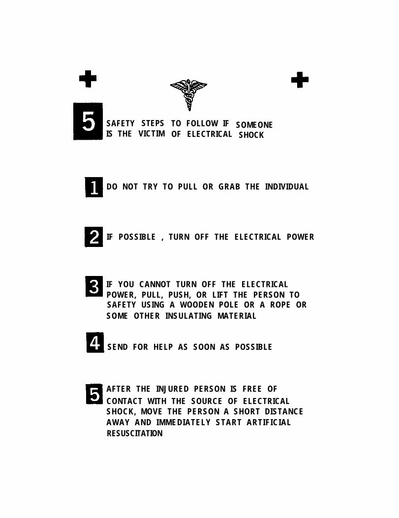
SAFETYIS THE
STEPSVICTIM
TO FOLLOW IFOF ELECTRICAL
SOMEONESHOCK
DO NOT TRY TO PULL OR GRAB THE INDIVIDUAL
IF POSSIBLE , TURN OFF THE ELECTRICAL POWER
IF YOU CANNOT TURN OFF THE ELECTRICALPOWER, PULL, PUSH, OR LIFT THE PERSON TOSAFETY USING A WOODEN POLE OR A ROPE ORSOME OTHER INSULATING MATERIAL
SEND FOR HELP AS SOON AS POSSIBLE
AFTER THE INJURED PERSON IS FREE OFCONTACT WITH THE SOURCE OF ELECTRICALSHOCK, MOVE THE PERSON A SHORT DISTANCEAWAY AND IMMEDIATELY START ARTIFICIALRESUSCITATION

TM 11-5841-283-12/NAVAIR 16-30APR39-1
WARNING
High voltage is used in the operation of this equipment.
DEATH ON CONTACT
may result if personnel fail to observe safety precautions. Learn the areas containinghigh voltage in each piece of equipment. Be careful not to contact high-voltageconnections when installing or operating this equipment. Before working inside theequipment, turn power off and ground points of high potential before touching them.
WARNING
Handle CRT (indicator screen) with extreme caution; implosion may result from carelesshandling.
Adequate venti lat ion should be provided while using TRICHLOROTRIFLUOROETHANE. Prolonged
breathing of vapor should be avoided. The solvent should not be used near heat or open flame;
the products o f decomposi t ion are tox ic and i r r i ta t ing. Since TRICHLOROTRIFLUOROETHANEdissolves natural oi ls, prolonged contact with skin should be avoided. When necessary, use
gloves which the solvent cannot penetrate. If the solvent is taken internally, consult a physician
i m m e d i a t e l y .
Aircraft with AN/APR-39(V)1 installed must not be located within 60 yards of activegroundbased radar antennas or 6 yards from active airborne radar antennas. Radarsignals within these distances will cause damage to the receivers and comparator ofAN/APR-39(V)1 .
Set 28 VDC circuit breaker OFF before removing or installing any subsystem ofAN/APR-39(V)1 (see aircraft manual). If power is on, removal or installation of anysubsystem may cause sparking which could ignite fuel vapors.
A/ (B blank)
*TM 11-5841-283-12NAVAIR 16-30APR39-1
Technical Manual
No. 11-5841-283-12
Technical Manual
NAVAIR 16-30APR39-1
DEPARTMENTS OF THE ARMY,
AND THE NAVY
Washington, DC, 9 A u g u s t 1 9 8 3
Aviation Unit MaintenanceManual
RADAR SIGNAL DETECTING SETAN/APR-39(V)1
(NSN 5841-01-023-7112)
REPORTING ERRORS AND RECOMMENDING IMPROVEMENTS
You can help improve this manual. If you find any mistakes or if you know of a way to improve the pro-cedures, please let us know. MaiI your letter, DA Form 2028 (Recommended Changes to Publicationsand Blank Forms), or DA Form 2028-2 located in back of this manual direct to: Commander, US ArmyCommunications-Electronics Command and Fort Monmouth, ATTN: DRSEL-ME-MP, Fort Monmouth,New Jersey 07703. For Navy, mail comments to the Commander, Naval Electronic Systems Command;ATTN: ELEX 8122, Washington, DC 20360. In either case a reply will be furnished direct to you.
CHAPTER 1
Section ISection IISection Ill
CHAPTER 2
Section ISection II
CHAPTER 3
CHAPTER 4
Section ISection IISection IllSection IVSection VSection VI
HOW TO USE THIS MANUAL. . . . . . . . . . . . . . . . . . . . . . . . . . . . . . . . . . . . . . .
INTRODUCTION . . . . . . . . . . . . . . . . . . . . . . . . . . . . . . . . . . . . . . . . . . . . . . . . .
General Information . . . . . . . . . . . . . . . . . . . . . . . . . . . . . . . . . . . . . . . . . . . . . .Equipment Description . . . . . . . . . . . . . . . . . . . . . . . . . . . . . . . . . . . . . . . . . . .Principles of operation . . . . . . . . . . . . . . . . . . . . . . . . . . . . . . . . . . . . . . . . . . .
OPERATING INSTRUCTIONS . . . . . . . . . . . . . . . . . . . . . . . . . . . . . . . . . . . . . .
Description and Use of Operator’s Controls and Indicators . . . . . . . . . . . . . .Operation Under Usual Conditions . . . . . . . . . . . . . . . . . . . . . . . . . . . . . . . . . .
MAINTENANCE OF AUXILIARY EQUIPMENT . . . . . . . . . . . . . . . . . . . . . . . . .
AVIATION UNIT MAINTENANCE . . . . . . . . . . . . . . . . . . . . . . . . . . . . . . . . . . . .
Repair Parts, Special Tools, TM DE, and Support Equipment . . . . . . . . . . . . .Service Upon Receipt. . . . . . . . . . . . . . . . . . . . . . . . . . . . . . . . . . . . . . . . . . . . .Aviation Unit PMCS . . . . . . . . . . . . . . . . . . . . . . . . . . . . . . . . . . . . . . . . . . . . .Aviation Unit Troubleshooting . . . . . . . . . . . . . . . . . . . . . . . . . . . . . . . . . . . .Maintenance Procedures. . . . . . . . . . . . . . . . . . . . . . . . . . . . . . . . . . . . . . . . . .Preparation for Storage or Shipment . . . . . . . . . . . . . . . . . . . . . . . . . . . . . . . .
Page
ii
1-1
1-11-41-10
2-1
2-12-3
3-1
4-1
4-14-24-334-414-454-91
* This manual supersedes TM 11-5841-283-20, 1 June 1977, including all changes.
i
TM 11-5841-283-12/NAVAIR 16-30APR39-1
APPENDIX A REFERENCES . . . . . . . . . . . . . . . . . . . . . . . . . . . . . . . . . . . . . . . . . . . . . . . . . . A-1
MAINTENANCE ALLOCATION CHART . . . . . . . . . . . . . . . . . . . . . . . . . . . . . . B-1
COMPONENTS OF END ITEM AND BASIC ISSUE ITEMS LIST . . . . . . . . . . . C-1
ADDITIONAL AUTHORIZATION LIST . . . . . . . . . . . . . . . . . . . . . . . . . . . . . . . . D-1
EXPENDABLE SUPPLIES AND MATERIALS LIST . . . . . . . . . . . . . . . . . E-1
GLOSSARY . . . . . . . . . . . . . . . . . . . . . . . . . . . . . . . . . . . . . . . . . . Glossary 1
INDEX . . . . . . . . . . . . . . . . . . . . . . . . . . . . . . . . Index 1
HOW TO USE THIS MANUAL
This manual is designed to help you operate and maintain the radar signal detectingset. The front cover table of contents is provided for quick reference to importantinformation. There is also an index located in the final pages for use in locatingspecific items of information.
Read all preliminary information found at the beginning of each task. It has importantinformation and safety instructions you must follow before beginning the task.
Warning pages are located in the front of this manual. You should learn the warningsbefore doing maintenance on the equipment.
Paragraphs in this manual are numbered by chapter and order of appearance within achapter. A subject index appears at the beginning of each chapter listing sectionsthat are included in that chapter. A more specific subject index is located at thebeginning of each section to help you find the exact paragraph you’re looking for.
ii/(iii blank)
Page
TM 11-5841-283-12/NAVAlR 16-30APR39-1
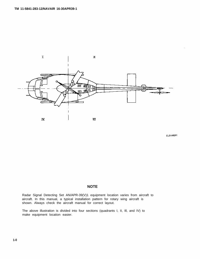
NOTE
Radar Signal Detecting Set AN/APR-39(V)1 equipment location varies from aircraft toaircraft. In this manual, a typical installation pattern for rotary wing aircraft isshown. Always check the aircraft manual for correct layout.
The above illustration is divided into four sections (quadrants I, II, Ill, and IV) tomake equipment location easier.
1-0
TM 11-5841-283-12/NAVAIR 16-30APR39-1
CHAPTER 1
INTRODUCTION
Subject
General Information. . . . . . . . . . . . . . . . . . . . . . . . . . . . . . . . . . . . . . . . . . . . . . . . . . . .Equipment Description . . . . . . . . . . . . . . . . . . . . . . . . . . . . . . . . . . . . . . . . . . Principles of Operation . . . . . . . . . . . . . . . . . . . . . . . . . . . . . . . . .
Section I GENERAL INFORMATION
Subject
Scope . . . . . . . . . . . . . . . . . . . . . . . . . . . . . . . . . . . . . . . . . . . . . . . . . . . . . . . . . . . . . . . . . . . . . . . . . . . Maintenance Forms, Records, and Reports . . . . . . . . . . . . . . . . . . . . . . . . . . . . . . . . .Destruction of Army Electronics Materiel . . . . . . . . . . . . . . . . . . . . . . . . . . . . . . . . . .Preparation for Storage or Shipment . . . . . . . . . . . . . . . . . . . . . . . . . . . . . . . . . . . . . .Reporting Equipment Improvement Recommendations . . . . . . . . . . . . . . . . . . . . . . .Nomenclature Cross-Reference List . . . . . . . . . . . . . . . . . . . . . . . . . . . . . . . . . . . . . .List of Abbreviations . . . . . . . . . . . . . . . . . . . . . . . . . . . . . . . . . . . . . . . . .
1-1. SCOPE.
Section
IIIIll
Para
1-11-21-31-41-51-61-7
Page
1-11-41-10
Page
1-11-21-21-21-21-31-3
Type of Manual: This manual covers Aviation Unit (organizational) level maintenance. Relatedmaintenance manuals TM 11-5841-283-34-1 and -2 classified supplement this manual and containinstructions for AVIM, (direct support) maintenance.
Equipment Name and Model Number: Radar Signal Detecting Set AN/APR-39(V)1,NSN 5841-01-023-7112.
Purpose of Equipment: The primary purpose of the Radar Signal Detecting Set AN/APR-39(V)1 is toreceive and display to the aircraft pilot, or other observer, information concerning radar andtracking signals which may be a potential threat. The radar signal detecting set can beinstalled in either rotary or fixed wing aircraft.
1-1
TM 11-5841-283-12/NAVAlR 16-30APR39-1
1-2. MAINTENANCE FORMS, RECORDS, AND REPORTS.
REPORTS OF MAINTENANCE AND UNSATISFACTORY EQUIPMENT
Department of the Army forms and procedures used for equipment maintenance will be thoseprescribed by TM 38-750, The Army Maintenance Management System (TAMMS). Navy personnel willreport maintenance performed utilizing the Maintenance Data Collection Subsystem (MDCS) IAWOPNAVINST 4790.2, vol. 3 and Unsatisfactory Material/Conditions (UR submissions) IAW OPNAVINST4790.2, vol. 2, chapter 17.
REPORT OF PACKAGING AND HANDLING DEFICIENCIES
Fill out and forward SF-364, Report of Discrepancy (ROD), as prescribed in AR 735-11-2/DLAR4140.55/NAVMATlNST 4355.73/AFR 400-54/MCO 4430.3E.
DISCREPANCY IN SHIPMENT REPORT (DISREP) (SF 361)
Fill out and forward Discrepancy in Shipment Report (DISREP) (SF 361) as prescribed in AR55-38 /NAVSUPlNST 4610.33B/AFR 75-18/MCO P4610.19C/DLAR 4500.15.
1-3. DESTRUCTION OF ARMY ELECTRONICS MATERIEL.
Destruction of Army electronics materiel to prevent enemy use shall be in accordance with TM750-244-2.
1-4. PREPARATION FOR STORAGE OR SHIPMENT.
Administrative storage of equipment issued to and used by Army activities will have preventivemaintenance performed in accordance with the PMCS charts before storing. When removing theequipment from administrative storage, the PMCS should be performed to assure operationalreadiness. Disassembly and repacking of equipment for shipment or limited storage are covered inchapter 4, section VI.
1-5. REPORTING EQUIPMENT IMPROVEMENT RECOMMENDATIONS.
If your radar signal detecting set needs improvement, let us know. Send us an EIR. You, theuser, are the only one who can tell us what you don’t like about your equipment. Let us know whyyou don’t like the design. Put in on an SF 368 (Quality Deficiency Report). Mail it to Commander, U.S.Army Communications-Electronics Command and Fort Monmouth, ATTN: DRSEL-ME-MP, FortMonmouth, New Jersey 07703. A reply will be sent to you. Navy personnel are encouraged to submitElR’s through their local Beneficial Suggestion Program.
1-2
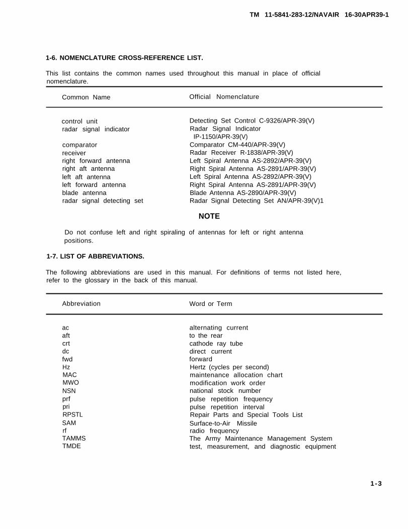
1-6. NOMENCLATURE CROSS-REFERENCE LIST.
This list contains the common names used throughout this manual in place of officialnomenclature.
Common Name Official Nomenclature
control unitradar signal indicator
comparatorreceiverright forward antennaright aft antennaleft aft antennaleft forward antennablade antennaradar signal detecting set
Detecting Set Control C-9326/APR-39(V)Radar Signal Indicator
IP-1150/APR-39(V)Comparator CM-440/APR-39(V)Radar Receiver R-1838/APR-39(V)Left Spiral Antenna AS-2892/APR-39(V)Right Spiral Antenna AS-2891/APR-39(V)Left Spiral Antenna AS-2892/APR-39(V)Right Spiral Antenna AS-2891/APR-39(V)Blade Antenna AS-2890/APR-39(V)Radar Signal Detecting Set AN/APR-39(V)1
NOTE
Do not confuse left and right spiraling of antennas for left or right antennapositions.
1-7. LIST OF ABBREVIATIONS.
The following abbreviations are used in this manual. For definitions of terms not listed here,refer to the glossary in the back of this manual.
Abbreviation Word or Term
acaftcrtdcfwdHzMACMWONSNprfpriRPSTLSAMrfTAMMSTMDE
alternating currentto the rearcathode ray tubedirect currentforwardHertz (cycles per second)maintenance allocation chartmodification work ordernational stock numberpulse repetition frequencypulse repetition intervalRepair Parts and Special Tools ListSurface-to-Air Missileradio frequencyThe Army Maintenance Management Systemtest, measurement, and diagnostic equipment
1-3
TM 11-5841-283-12/NAVAIR 16-30APR39-1
TM 11-5841-283-12/NAVAIR 16-30APR39-1
Section II EQUIPMENT DESCRIPTION
Subject
Equipment Characteristics . . . . . . . . . . . . . . . . . . . . . . . . . . . . . . . . . . . . . . . . . . . . . .Capabilities and Features . . . . . . . . . . . . . . . . . . . . . . . . . . . . . . . . . . . . . . . . . . . . . . .Location and Description of Major Components. . . . . . . . . . . . . . . . . . . . . . . . . . . . .Equipment Data . . . . . . . . . . . . . . . . . . . . . . . . . . . . . . . . . . . . . . . . . . . . . . . . . . . . . . .Safety, Care, and Handling . . . . . . . . . . . . . . . . . . . . . . . . . . . . . . . . . . . . . . . . . . . . . .
1-8. EQUIPMENT CHARACTERISTICS.
Para
1-81-91-101-111-12
The radar signal detecting set consists of ten individually packaged components:
control unitradar signal indicatorcomparatortwo radar receiversfour spiral antennasblade antenna
1-9. CAPABILITIES AND FEATURES.
The radar signal detecting set provides the following capabilities and features:
Can be operated in all weather and climate conditionsLightweight and compactCan reinstalled in rotary wing or fixed wing aircraftResponds to radars associated with hostile fire control systemsGenerally excludes nonthreat radars in the discriminator-on modeAccepts Iow band missile guidance radar signalsWhen a low band signal is time-coincident (correlated) with attacking radar signal, the
equipment identifies the combination as an activated SAM (surface to air missile) radarcomplex
Offers both visual and aural warning displays
Page
1-41-41-51-71-10
1-4
TM 11-5841-283-12/NAVAIR 16-30APR39-1
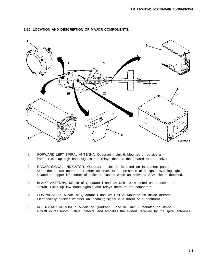
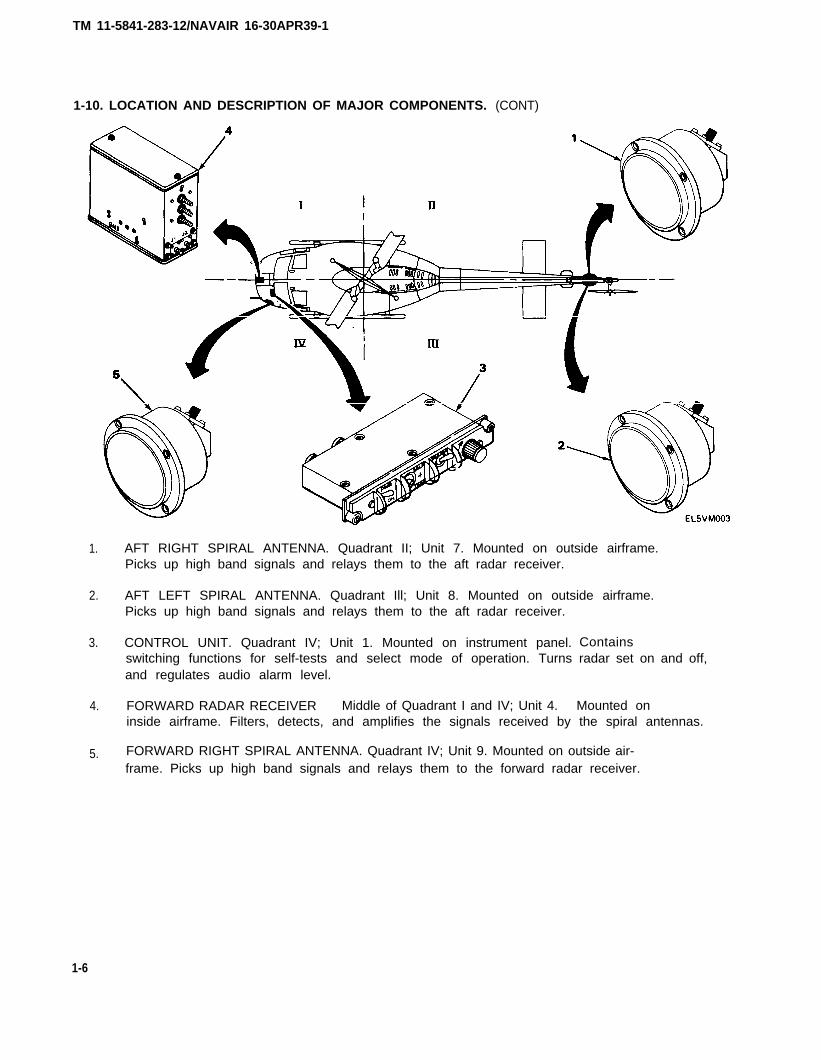
1-10. LOCATION AND DESCRIPTION OF MAJOR COMPONENTS.
1.
2.
3.
4.
5.
FORWARD LEFT SPIRAL ANTENNA. Quadrant I; Unit 6. Mounted on outside air-frame. Picks up high band signals and relays them to the forward radar receiver.
RADAR SIGNAL INDICATOR. Quadrant I; Unit 2. Mounted on instrument panel.Alerts the aircraft operator, or other observer, to the presence of a signal. Warning light,located on upper left corner of indicator, flashes when an activated SAM site is detected.
BLADE ANTENNA. Middle of Quadrant I and IV; Unit 10. Mounted on underside ofaircraft. Picks up low band signals and relays them to the comparator.
COMPARATOR. Middle of Quadrant I and IV; Unit 3. Mounted on inside airframe.Electronically decides whether an incoming signal is a threat or a nonthreat.
AFT RADAR RECEIVER. Middle of Quadrant II and Ill; Unit 5. Mounted on insideaircraft in tail boom. Filters, detects, and amplifies the signals received by the spiral antennas.
1-5
TM 11-5841-283-12/NAVAIR 16-30APR39-1
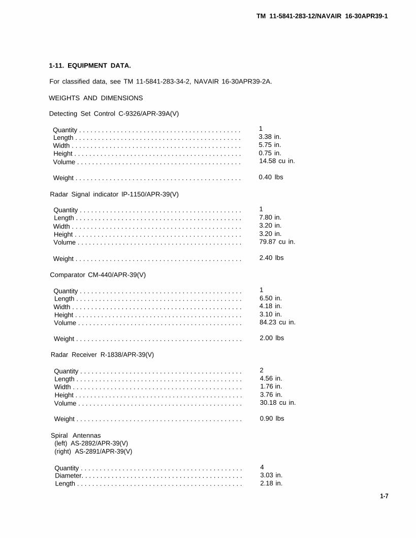
1-10. LOCATION AND DESCRIPTION OF MAJOR COMPONENTS.
1.
2.
3.
4.
5.
(CONT)
AFT RIGHT SPIRAL ANTENNA. Quadrant II; Unit 7. Mounted on outside airframe.Picks up high band signals and relays them to the aft radar receiver.
AFT LEFT SPIRAL ANTENNA. Quadrant Ill; Unit 8. Mounted on outside airframe.Picks up high band signals and relays them to the aft radar receiver.
CONTROL UNIT. Quadrant IV; Unit 1. Mounted on instrument panel.switching functions for self-tests and select mode of operation. Turnsand regulates audio alarm level.
FORWARD RADAR RECEIVER Middle of Quadrant I and IV; Unit 4.
Containsradar set on and off,
Mounted oninside airframe. Filters, detects, and amplifies the signals received by the spiral antennas.
FORWARD RIGHT SPIRAL ANTENNA. Quadrant IV; Unit 9. Mounted on outside air-frame. Picks up high band signals and relays them to the forward radar receiver.
1-6
TM 11-5841-283-12/NAVAIR 16-30APR39-1
1-11. EQUIPMENT DATA.
For classified data, see TM 11-5841-283-34-2, NAVAIR 16-30APR39-2A.
WEIGHTS AND DIMENSIONS
Detecting Set Control C-9326/APR-39A(V)
Quantity . . . . . . . . . . . . . . . . . . . . . . . . . . . . . . . . . . . . . . . . . . .Length . . . . . . . . . . . . . . . . . . . . . . . . . . . . . . . . . . . . . . . . . . . .Width . . . . . . . . . . . . . . . . . . . . . . . . . . . . . . . . . . . . . . . . . . . . .Height . . . . . . . . . . . . . . . . . . . . . . . . . . . . . . . . . . . . . . . . . . . . .Volume . . . . . . . . . . . . . . . . . . . . . . . . . . . . . . . . . . . . . . . . . . . .
Weight . . . . . . . . . . . . . . . . . . . . . . . . . . . . . . . . . . . . . . . . . . . .
Radar Signal indicator lP-1150/APR-39(V)
Quantity . . . . . . . . . . . . . . . . . . . . . . . . . . . . . . . . . . . . . . . . . . .Length . . . . . . . . . . . . . . . . . . . . . . . . . . . . . . . . . . . . . . . . . . . .Width . . . . . . . . . . . . . . . . . . . . . . . . . . . . . . . . . . . . . . . . . . . . .Height . . . . . . . . . . . . . . . . . . . . . . . . . . . . . . . . . . . . . . . . . . . .Volume . . . . . . . . . . . . . . . . . . . . . . . . . . . . . . . . . . . . . . . . . . . .
Weight . . . . . . . . . . . . . . . . . . . . . . . . . . . . . . . . . . . . . . . . . . . .
Comparator CM-440/APR-39(V)
Quantity . . . . . . . . . . . . . . . . . . . . . . . . . . . . . . . . . . . . . . . . . . .Length . . . . . . . . . . . . . . . . . . . . . . . . . . . . . . . . . . . . . . . . . . . .Width . . . . . . . . . . . . . . . . . . . . . . . . . . . . . . . . . . . . . . . . . . . . .Height . . . . . . . . . . . . . . . . . . . . . . . . . . . . . . . . . . . . . . . . . . . . .Volume . . . . . . . . . . . . . . . . . . . . . . . . . . . . . . . . . . . . . . . . . . . .
Weight . . . . . . . . . . . . . . . . . . . . . . . . . . . . . . . . . . . . . . . . . . . .
Radar Receiver R-1838/APR-39(V)
Quantity . . . . . . . . . . . . . . . . . . . . . . . . . . . . . . . . . . . . . . . . . . .Length . . . . . . . . . . . . . . . . . . . . . . . . . . . . . . . . . . . . . . . . . . . .Width . . . . . . . . . . . . . . . . . . . . . . . . . . . . . . . . . . . . . . . . . . . . .Height . . . . . . . . . . . . . . . . . . . . . . . . . . . . . . . . . . . . . . . . . . . . .Volume . . . . . . . . . . . . . . . . . . . . . . . . . . . . . . . . . . . . . . . . . . . .
Weight . . . . . . . . . . . . . . . . . . . . . . . . . . . . . . . . . . . . . . . . . . . .
Spiral Antennas(left) AS-2892/APR-39(V)(right) AS-2891/APR-39(V)
Quantity . . . . . . . . . . . . . . . . . . . . . . . . . . . . . . . . . . . . . . . . . . .Diameter. . . . . . . . . . . . . . . . . . . . . . . . . . . . . . . . . . . . . . . . . . .Length . . . . . . . . . . . . . . . . . . . . . . . . . . . . . . . . . . . . . . . . . . . .
13.38 in.5.75 in.0.75 in.14.58 cu in.
0.40 lbs
17.80 in.3.20 in.3.20 in.79.87 cu in.
2.40 lbs
16.50 in.4.18 in.3.10 in.84.23 cu in.
2.00 lbs
24.56 in.1.76 in.3.76 in.30.18 cu in.
0.90 lbs
43.03 in.2.18 in.
1-7
TM 11-5841-283-12/NAVAIR 16-30APR39-1
1-11. EQUIPMENT DATA. (CONT)
WEIGHTS AND DIMENSIONS (CONT)
Spiral Antennas (Cont)
Volume . . . . . . . . . . . . . . . . . . . . . . . . . . . . . . . . . . . . . . . . . . . . 15.71 cu in.
Weight . . . . . . . . . . . . . . . . . . . . . . . . . . . . . . . . . . . . . . . . . . . . 0.30 Ibs
Blade Antenna AS-2890/APR-39(V)
Quantity . . . . . . . . . . . . . . . . . . . . . . . . . . . . . . . . . . . . . . . . . . . 1Length . . . . . . . . . . . . . . . . . . . . . . . . . . . . . . . . . . . . . . . . . . . 5.25 in.Width . . . . . . . . . . . . . . . . . . . . . . . . . . . . . . . . . . . . . . . . . . . . . 1.75 in.Height . . . . . . . . . . . . . . . . . . . . . . . . . . . . . . . . . . . . . . . . . . . . . 3.68 in.Volume . . . . . . . . . . . . . . . . . . . . . . . . . . . . . . . . . . . . . . . . . . . . 33.81 cu in.
Weight . . . . . . . . . . . . . . . . . . . . . . . . . . . . . . . . . . . . . . . . . . . . 0.40 lbs
Total weight . . . . . . . . . . . . . . . . . . . . . . . . . . . . . . . . . . . . . . . . 8.20 lbs
FREQUENCY COVERAGE
Classified information.
RECEPTION COVERAGE
Classified information.
DIRECTION FINDING TECHNIQUE
Four Spiral Antenna Pattern. Each spiral antenna is oriented to one intercardinal axis, and isassociated to each of the radar signal indicator quadrants as follows:
Forward left spiral antenna- Upper left indicator quadrantForward right spiral antenna- Upper right indicator quadrantAft right spiral antenna- Lower right indicator quadrantAft left spiral antenna- Lower left indicator quadrant
ANTENNA CHARACTERISTICS
Classified information.
OPERATIONAL SENSITIVITY
Classified information.
THREAT IDENTIFICATION CRITERIA
Classified information.
1-8
TM 11-5841-283-12/NAVAIR 16-30APR39-1
1-11. EQUIPMENT DATA. (CONT)
VISUAL DISPLAY
Direction Type: Strobes appear on indicator screen showing from which direction a possiblethreat has been identified.
Direction Accuracy: Classified information.
Threat (Missile): Associated strobe and missile alert (MA) lamp flash alternately.
AUDIO OUTPUT
PRF audio and alarm audio superimposed when missile threat is identified.
SELF-TEST
Built-in capability activated by control unit pushbutton. Checks most radar signal detecting setcircuits, except RF.
EXTERNAL POWER REQUIREMENTS
Aircraft Power: 28 vdc at 1.1 amp maximum average.Aircraft Instrument Panel Dimmer: 0-28 vdc at 0.08 amp maximum.
ENVIRONMENTAL LIMITS
Operating Temperature: -54°C (-65.2°F) to 71oC (159.8°F) for all components exceptcontrol unit and indicator which are limited to 55°C (131oF).
Storage Temperature: -62°C (-79.6oF) to 71oC (159.8°F).
Altitude: 30,000 feet maximum.
Humidity: 0-100%.
BLANKING INPUT (OPERATIONAL)
Pulse Width: Must bracket transmitted pulse.Polarity: Positive.Amplitude: Between 2 and 30 volts, baseline 0 ± 0.05 volts.Duty Cycle: Classified information.Impedance, Input: 330 ohms ± 10%.
1-9
TM 11-5841-283-12/NAVAIR 16-30APR39-1
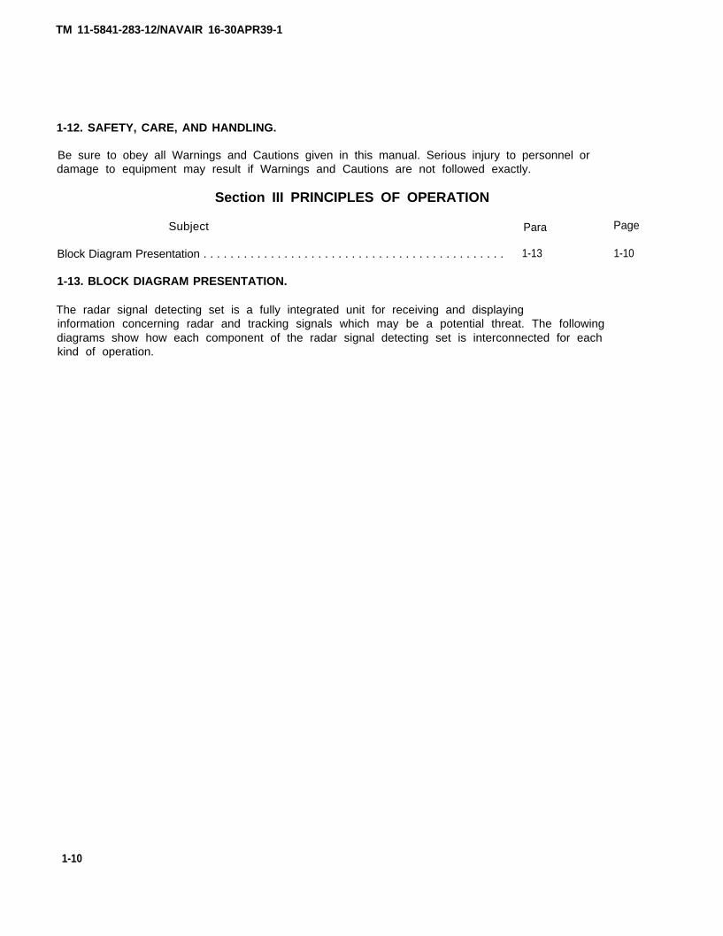
1-12. SAFETY, CARE, AND HANDLING.
Be sure to obey all Warnings and Cautions given in this manual. Serious injury to personnel ordamage to equipment may result if Warnings and Cautions are not followed exactly.
Section III PRINCIPLES OF OPERATION
Subject Para
Block Diagram Presentation . . . . . . . . . . . . . . . . . . . . . . . . . . . . . . . . . . . . . . . . . . . . . 1-13
1-13. BLOCK DIAGRAM PRESENTATION.
The radar signal detecting set is a fully integrated unit for receiving and displayinginformation concerning radar and tracking signals which may be a potential threat. The followingdiagrams show how each component of the radar signal detecting set is interconnected for eachkind of operation.
Page
1-10
1-10

TM 11-5841-283-12/NAVAIR 16-30APR39-1
1-13. BLOCK DIAGRAM PRESENTATION. (CONT)
SIGNAL INPUT AND AMPLIFICATION
1.
2.
3.
4.
5.
6.
7.
FORWARD LEFT SPIRAL ANTENNA (Unit 6). Picks up high band signals between
0° - 90° relative to aircraft heading and transmits them to the forward radar receiver.
FORWARD RIGHT SPIRAL ANTENNA (Unit 9). Picks up high band signals between
270° - 360° relative to aircraft heading and transmits them to the forward radar receiver.
AFT RIGHT SPIRAL ANTENNA (Unit 7). Picks up high band signals between 90° - 180°relative to aircraft heading and transmits them to the aft radar receiver.
AFT LEFT SPIRAL ANTENNA (Unit 8). Picks up high band signals between 180° - 270°relative to aircraft heading and transmits them to the aft radar receiver.
BLADE ANTENNA (Unit 10). Picks up low band signals and transmits them to thecomparator. The blade antenna is omnidirectional.
FORWARD RADAR RECEIVER (Unit 4). Filters, detects, and amplifies the high bandsignals from the forward right and forward left spiral antennas. The radar receiver convertshigh band signals to video signals.
AFT RADAR RECEIVER (Unit 5). Filters, detects, and amplifies the high band signalsfrom the aft right and aft left spiral antennas. The radar receiver converts high bandsignals to video signals.
1-11

TM 11-5841-283-12/NAVAIR 16-30APR39-1
1-13. BLOCK DIAGRAM PRESENTATION. (CONT)
THREAT/NONTHREAT DETERMINATION
1.
2.
3.
COMPARATOR (Unit 3). Electronically decides whether received signals meetnecessary conditions to indicate either a threat or a nonthreat. The comparator receiveshigh band signals from the spiral antennas and low band signals from the blade antenna. Ifvideo signals (high band) are correlated with low band signals, the comparator will activatethe MA lamp and audio alarm system, indicating the presence of an activated SAMradar complex.
RADAR SIGNAL INDICATOR (Unit 2). Provides visual display warning of a possiblethreat. The indicator is divided into four quadrants, each quadrant representing the areascanned by one of the four spiral antennas located around the aircraft. The indicatorreceives direction video signals from the comparator, which are displayed on the indicatorscreen as a strobe in the direction of the radar emitter.
CONTROL UNIT (Unit 1). Contains all switching functions necessary to perform self-tests and select mode of operation.
1-12
TM 11-5841-283-12/NAVAIR 16-30APR39-1
CHAPTER 2
OPERATING INSTRUCTIONS
Subject Section Page
Description and Use of Operator’s Controls and Indicators. . . . . . . . . . . . . . . . . . . . I 2-1Operation Under Usual Conditions . . . . . . . . . . . . . . . . . . . . . . . . . . . . . . . . . . . . . . . . II 2-3
Section I DESCRIPTION AND USE OF OPERATOR’S CONTROLS AND INDICATORS
Subject Para Page
Control Unit . . . . . . . . . . . . . . . . . . . . . . . . . . . . . . . . . . . . . . . . . . . . . . . . . . . . . . . . . 2-1 2-1Radar Signal Indicator. . . . . . . . . . . . . . . . . . . . . . . . . . . . . . . . . . . . . . . . . . . . . . . . . . 2-2 2-2
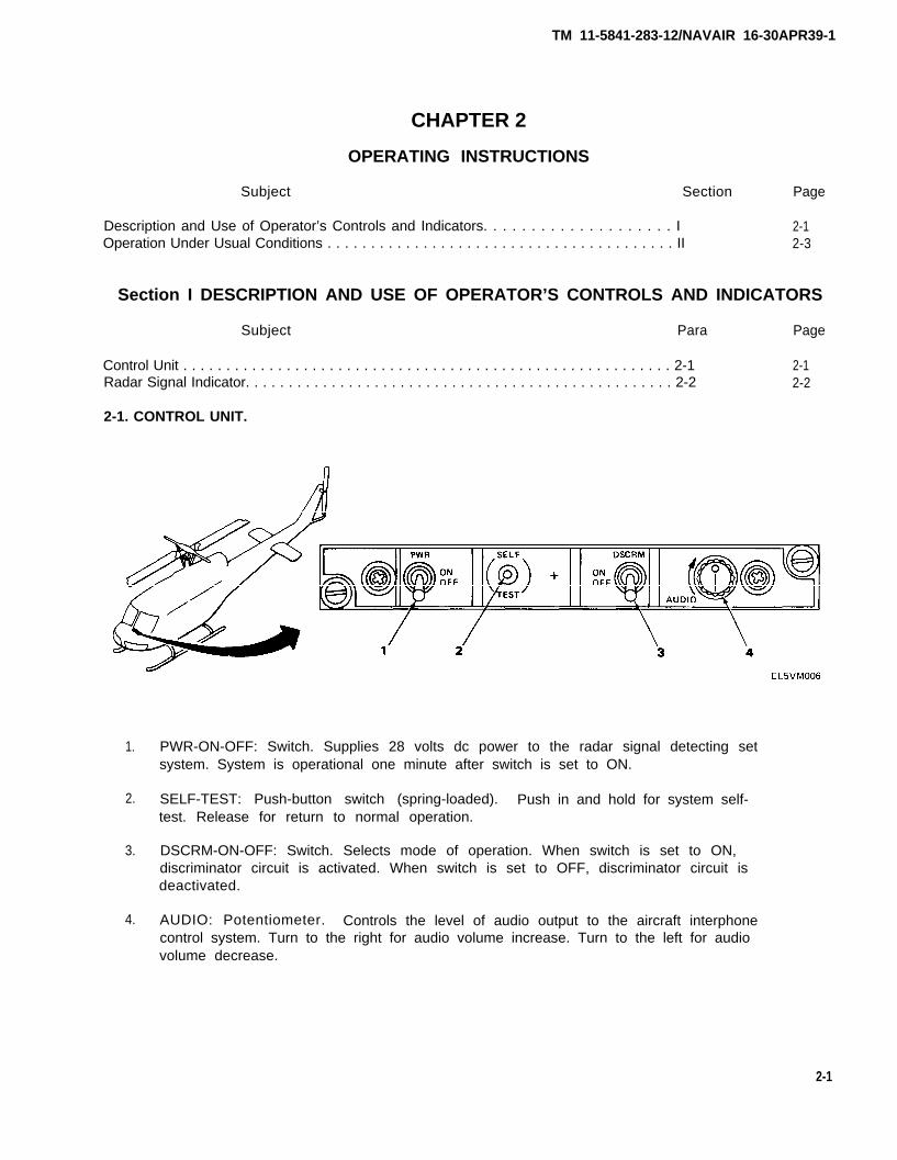
2-1. CONTROL UNIT.
1. PWR-ON-OFF: Switch. Supplies 28 volts dc power to the radar signal detecting setsystem. System is operational one minute after switch is set to ON.
2. SELF-TEST: Push-button switch (spring-loaded). Push in and hold for system self-test. Release for return to normal operation.
3. DSCRM-ON-OFF: Switch. Selects mode of operation. When switch is set to ON,discriminator circuit is activated. When switch is set to OFF, discriminator circuit isdeactivated.
4. AUDIO: Potentiometer. Controls the level of audio output to the aircraft interphonecontrol system. Turn to the right for audio volume increase. Turn to the left for audiovolume decrease.
2-1

TM 11-5841-283-12/NAVAIR 16-30APR39-1
2-2. RADAR SIGNAL INDICATOR.
1.
2.
3.
4.
5.
INDICATOR SCREEN: CRT. Shows a line-of-bearing radial strobe for eachprocessed signal received by the spiral antennas.
MA: Missle alert lamp. In the discriminator-on mode, flashes on and off to indicatean immediate threat. Lamp flashes when low band signals associated with missile guidancesystems are correlated with high band signals associated with radar tracking systems (SAMradar complex). In the discriminator-off mode, flashes when processed low band signals areintercepted.
MA LAMP SHIELD: Missile alert lamp shield. Reduces MA lamp brightness whenaircraft pilot is wearing right vision glasses.
BRIL: Potentiometer. Varies the brilliance of the indicator strobe. Used togetherwith the filter control to produce a highly visible and clear display under mostlighting conditions.
NIGHT-DAY: Filter. Varies the density of the red polarizing face plate filter for dayor night operation. Used together with the BRIL control to produce a highly visible andclear display under most lighting conditions.
2-2
TM 11-5841-283-12/NAVAIR 16-30APR39-1
Section II OPERATION UNDER USUAL CONDITIONS
Subject Para
Turn-On Procedures . . . . . . . . . . . . . . . . . . . . . . . . . . . . . . . . . . . . . . . . . . . . . . . . . . . . 2-3Self-Test . . . . . . . . . . . . . . . . . . . . . . . . . . . . . . . . . . . . . . . . . . . . . . . . . . . . . . . . . . . . . 2-4Shutdown Procedures. . . . . . . . . . . . . . . . . . . . . . . . . . . . . . . . . . . . . . . . . . . . . . . . . . 2-5
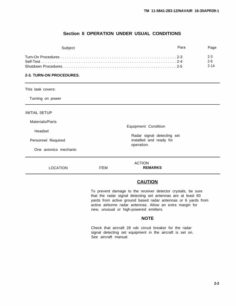
2-3. TURN-ON PROCEDURES.
Page
2-32-62-14
This task covers:
Turning on power
INITIAL SETUP
Materials/PartsEquipment Condition
HeadsetRadar signal detecting set
Personnel Required installed and ready foroperation.
One avionics mechanic
ACTIONLOCATION ITEM REMARKS
CAUTION
To prevent damage to the receiver detector crystals, be surethat the radar signal detecting set antennas are at least 60yards from active ground based radar antennas or 6 yards fromactive airborne radar antennas. AlIow an extra margin fornew, unusual or high-powered emitters.
NOTE
Check that aircraft 28 vdc circuit breaker for the radarsignal detecting set equipment in the aircraft is set on.See aircraft manual.
2-3
TM 11-5841-283-12/NAVAIR 16-30APR39-1
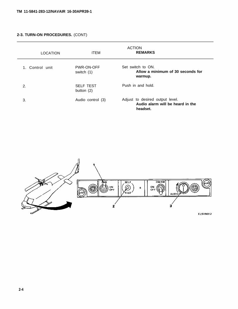
2-3. TURN-ON PROCEDURES. (CONT)
ACTIONLOCATION ITEM REMARKS
1. Control unit PWR-ON-OFF Set switch to ON.switch (1) Allow a minimum of 30 seconds for
warmup.
2. SELF TEST Push in and hold.button (2)
3. Audio control (3) Adjust to desired output level.Audio alarm will be heard in theheadset.
2-4
TM 11-5841-283-12/NAVAIR 16-30APR39-1
2-3. TURN-ON PROCEDURES. (CONT)
ACTIONLOCATION ITEM REMARKS
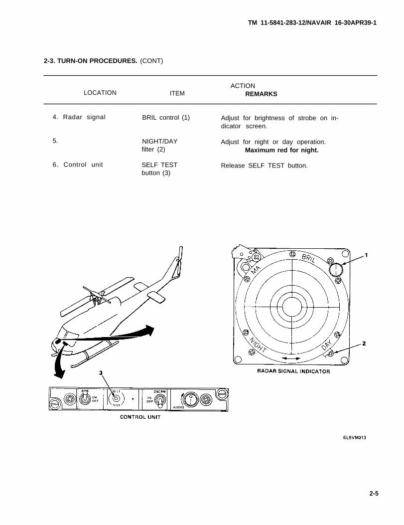
4. Radar signal BRIL control (1) Adjust for brightness of strobe on in-dicator screen.
5.
6. Control unit
NIGHT/DAYfilter (2)
SELF TESTbutton (3)
Adjust for night or day operation.Maximum red for night.
Release SELF TEST button.
2-5
2-4. SELF-TEST.
This task covers:
Testing the radar signal detecting set circuits
INITIAL SETUP
Materials/PartsEquipment Condition
HeadsetRadar signal detecting set
Personnel Required installed and ready foroperation.
One avionics mechanic
ACTIONLOCATION ITEM REMARKS
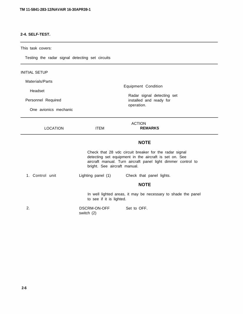
1. Control unit
2.
NOTE
Check that 28 vdc circuit breaker for the radar signaldetecting set equipment in the aircraft is set on. Seeaircraft manual. Turn aircraft panel light dimmer control tobright. See aircraft manual.
Lighting panel (1) Check that panel lights.
NOTE
In well lighted areas, it may be necessary to shade the panelto see if it is lighted.
DSCRM-ON-OFF Set to OFF.switch (2)
2-6
TM 11-5841-283-12/NAVAIR 16-30APR39-1
TM 11-5841-283-12/NAVAIR 16-30APR39-1
2-4. SELF-TEST. (CONT)
ACTIONLOCATION ITEM REMARKS
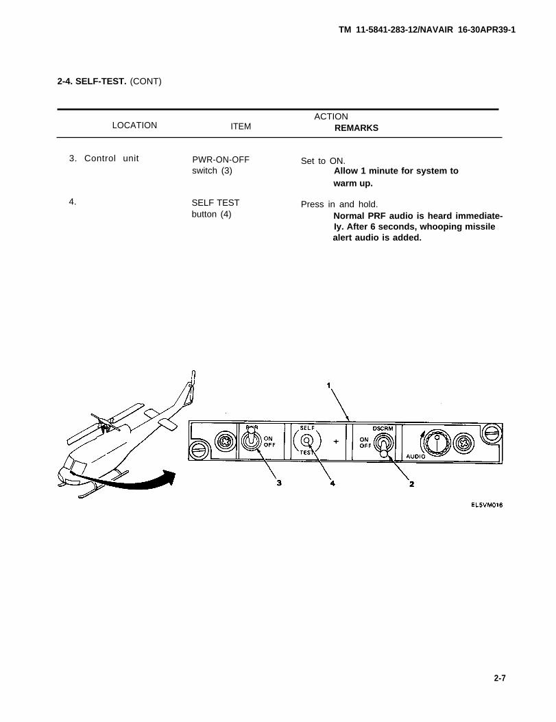
3. Control unit PWR-ON-OFF Set to ON.switch (3) Allow 1 minute for system to
warm up.
4. SELF TEST Press in and hold.button (4) Normal PRF audio is heard immediate-
Iy. After 6 seconds, whooping missilealert audio is added.
2-7

TM 11-5841-283-12/NAVAIR 16-30APR39-1
2-4. SELF-TEST. (CONT)
ACTIONLOCATION ITEM REMARKS
5. Radar signal Indicator Observe.screen (1) Immediately, forward and aft strobes
appear, extending to about the thirdcircle on the indicator screen.
6. MA lamp (2) Observe.After 6 seconds, MA lamp startsflashing.
2-8

TM 11-5841-283-12/NAVAIR 16-30APR39-1
2-4. SELF-TEST. (CONT)
ACTIONLOCATION ITEM REMARKS
7. Radar signal BRIL control (1) Turn left or right.indicator Strobes on indicator screen will
brighten or dim as control is turned.
NOTE
Strobes will brighten if control is turned clockwise.Strobes will dim if control is turned counterclockwise.
2-9
TM 11-5841-283-12/NAVAIR 16-30APR39-1
2-4. SELF-TEST. (CONT)
ACTIONLOCATION ITEM REMARKS
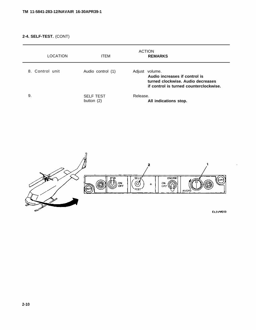
8. Control unit Audio control (1) Adjust volume.Audio increases if control isturned clockwise. Audio decreasesif control is turned counterclockwise.
9. SELF TESTbutton (2)
Release.All indications stop.
2-10

TM 11-5841-283-12/NAVAIR 16-30APR39-1
2-4. SELF-TEST. (CONT)
ACTIONLOCATION ITEM REMARKS
10. Control unit DSCRM-ON-OFF Set to ON.switch (1)
11. SELF TEST Press in and hold.button (2) PRF audio is heard after 4 seconds.
After a few more seconds, PRF audiowill double. Within another fewseconds, alarm audio will be heard.
2-11

TM 11-5841-283-12/NAVAIR 16-30APR39-1
2-4. SELF-TEST. (CONT)
ACTION
LOCATION ITEM REMARKS
12. Radar signal Indicator Observe.
indicator screen (1) Within about 4 seconds, forwardor aft strobe appears. Oppositestrobe will appear within the nextfew seconds.
NOTE
Sometimes, after pushing in the SELF TEST button and beforethe appearance of the first strobe, a distorted dot on theindicator and off-and-on audio will be present. This is nota fault indication. Hold SELF TEST button in long enough forstrobes to appear.
13. MA lamp (2) Observe.Six seconds after pressing SELF TEST,MA lamp starts flashing.
2-12
TM 11-5841-283-12/NAVAIR 16-30APR39-1
2-4. SELF-TEST. (CONT)
ACTIONLOCATION ITEM REMARKS
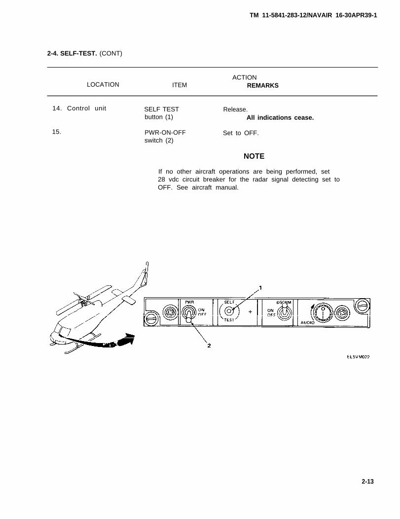
14. Control unit SELF TEST Release.button (1) All indications cease.
15. PWR-ON-OFF Set to OFF.switch (2)
NOTE
If no other aircraft operations are being performed, set28 vdc circuit breaker for the radar signal detecting set toOFF. See aircraft manual.
2-13
TM 11-5841-283-12/NAVAIR 16-30APR39-1
2-5. SHUTDOWN PROCEDURES.
This task covers:
Shutting down the radar signal detecting set
INITIAL SETUP
Personnel Required
One operator
Equipment Condition
Radar signal detecting setis on.
ACTIONLOCATION ITEM REMARKS
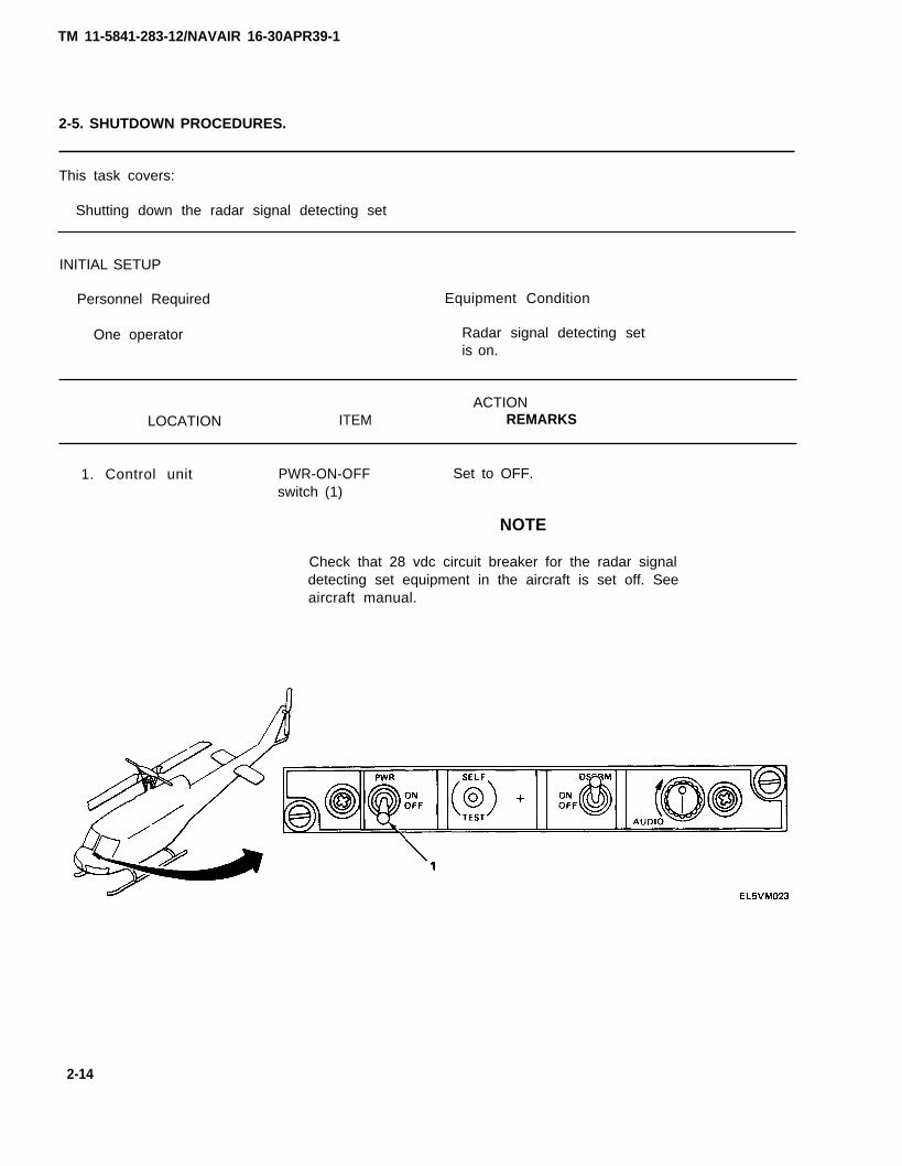
1. Control unit PWR-ON-OFF Set to OFF.switch (1)
NOTE
Check that 28 vdc circuit breaker for the radar signaldetecting set equipment in the aircraft is set off. Seeaircraft manual.
2-14
TM 11-5841-283-12/NAVAIR 16-30APR39-1
CHAPTER 3
MAINTENANCE OF AUXILIARY EQUIPMENT
There is no auxiliary equipment requiring maintenance for the Radar Signal Detecting SetAN/APR-39(V)1 .
3-1/(3-2 blank)
TM 11-5841-283-12/NAVAIR 16-30APR39-1
CHAPTER 4
AVIATION UNIT MAINTENANCE
Subject Section Page
Repair Parts, Special Tools, TMDE, and Support Equipment . . . . . . . . . . . . . . . . . . . I 4-1Service Upon Receipt . . . . . . . . . . . . . . . . . . . . . . . . . . . . . . . . . . . . . . . . . . . . . . . . . . II 4-2Preventive Maintenance Checks and Services . . . . . . . . . . . . . . . . . . . . . . . . . . . . . . Ill 4-33Troubleshooting . . . . . . . . . . . . . . . . . . . . . . . . . . . . . . . . . . . . . . . . . . . . . . . . . . . . . . . IV 4-41Maintenance Procedures . . . . . . . . . . . . . . . . . . . . . . . . . . . . . . . . . . . . . . . . . . . . . . . V 4-45Preparation for Storage or Shipment . . . . . . . . . . . . . . . . . . . . . . . . . . . . . . . . . . . . . . VI 4-92
OVERVIEW
This chapter covers instructions for performing aviation unit (organizational) maintenance ofthe radar signal detecting set from initial receipt of equipment.
Section I REPAIR PARTS, SPECIAL TOOLS, TMDE, AND SUPPORT EQUIPMENT
Subject Para Page
Common Tools and Equipment . . . . . . . . . . . . . . . . . . . . . . . . . . . . . . . . . . . . . . . . . . . 4-1 4-1Special Tools, TMDE, and Support Equipment . . . . . . . . . . . . . . . . . . . . . . . . . . . . . . 4-2 4-1Repair Parts . . . . . . . . . . . . . . . . . . . . . . . . . . . . . . . . . . . . . . . . . . . . . . . . . . . . . . . . . . 4-3 4-1
4-1. COMMON TOOLS AND EQUIPMENT.
The common tools and equipment needed for each maintenance function are listed in the lnitialSetup section before each maintenance task, and a complete listing is shown in the MaintenanceAllocation Chart listed in appendix B.
4-2. SPECIAL TOOLS, TMDE, AND SUPPORT EQUIPMENT.
Special tools, TMDE, and support equipment needed for each maintenance function are shown in theMaintenance Allocation Chart listed in appendix B.
4-3. REPAIR PARTS.
The repair parts for AVUM maintenance are listed and shown in the Repair Parts and Special ToolsList, TM 11-5341-233-24P, which covers AVUM and AVIM maintenance for the Radar Signal DetectingSet AN/APR-39(V)-1.
4-1
TM 11-5841-283-12/NAVAIR 16-30APR39-1
Section
Subject
II
Unpacking. . . . . . . . . . . . . . . . . . . . . . . . . . . .Checking Unpacked Material . . . . . . . . . . . .
SERVICE UPON RECEIPT
. . . . . . .
. . . . . . .Initial Installation of Equipment . . . . . . . . . . . . . . . . .Tools, Test Equipment, and Materials Required
For Initial Installation . . . . . . . . . . . . . . . . . . . . . . . .Cable Connections . . . . . . . . . . . . . . . . . . . . . . . . . . .Installation of Plug-In Items . . . . . . . . . . . . . . . . . . . .Preliminary Servicing and Adjustment of Equipment
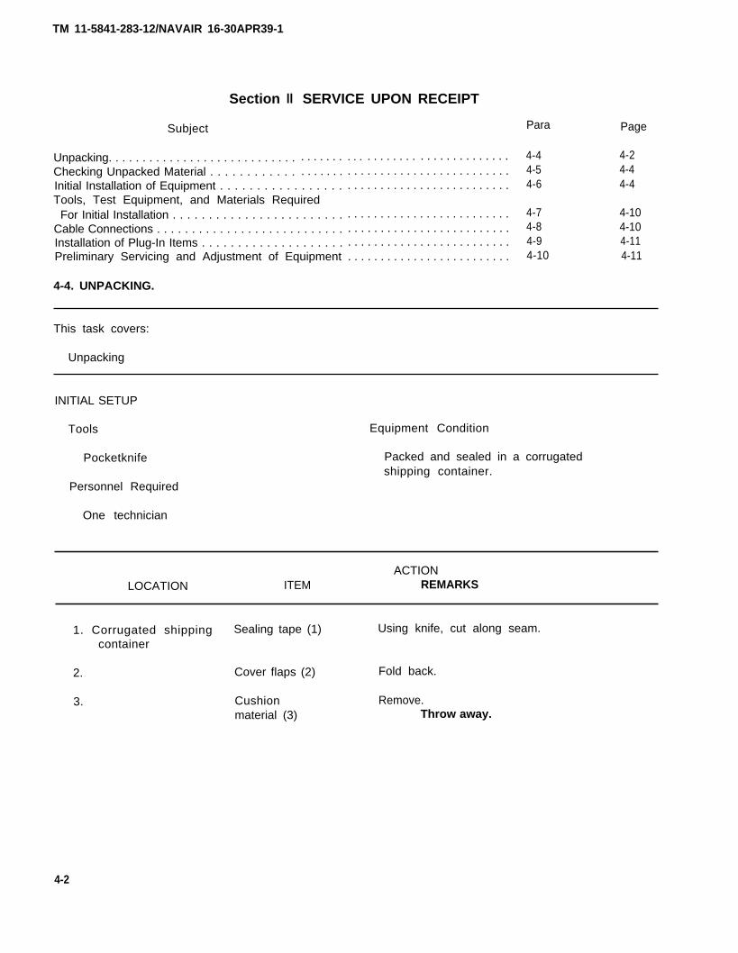
4-4. UNPACKING.
. . . . . . . . . . . . . . . . . . . . . . . . .
. . . . . . . . . . . . . . . . . . . . . . . . .
. . . . . . . . . . . . . . . . . . . . . . . . .
. . . . . . . . . . . . . . . . . . . . . . . . .
. . . . . . . . . . . . . . . . . . . . . . . . .
. . . . . . . . . . . . . . . . . . . . . . . . .
. . . . . . . . . . . . . . . . . . . . . . . . .
Para
4-44-54-6
4-74-84-94-10
Page
4-24-44-4
4-104-104-114-11
This task covers:
Unpacking
INITIAL SETUP
Tools
Pocketknife
Personnel Required
One technician
Equipment Condition
Packed and sealed in a corrugatedshipping container.
ACTIONLOCATION ITEM REMARKS
1. Corrugated shipping Sealing tape (1) Using knife, cut along seam.container
2.
3.
Cover flaps (2)
Cushionmaterial (3)
Fold back.
Remove.Throw away.
4-2
TM 11-5841-283-12/NAVAIR 16-30APR39-1
4-4. UNPACKING. (CONT)
ACTIONLOCATION ITEM REMARKS
4. Corrugatedshippingcontainer
5. Unit containers
6.
7.
8.
Unitcontainers (4)
Sealing tape (5)and coverflaps (5)
Component (7)
Waterproofwrapping (8)
Cushion mate-rial (9)
Remove.There are 10 containers, onefor each radar set component.
Cut along seam and fold back flaps.
Remove.Save container.
Open and remove.Throw away.
Remove.Throw away.
4-3
TM 11-5841-283-12/NAVAIR 16-30APR39-1
4-5. CHECKING UNPACKED MATERIAL.
Inspect all 10 components of the radar signal detecting set for any damage that may haveresulted from shipment. Make sure the shipment is complete and that all components listed on thepacking slip are accounted for. If any damage or discrepancies are found, report themimmediately. For proper forms and records, see paragraph 1-2.
Check the equipment for modifications. Modified equipment will have the MWO number on the frontpanel, near the nomenclature plate. Check that all currently applicable MWO’s have been applied.Current MWO’s applicable to the equipment are listed in DA Pam 310-1.
4-6. INITIAL INSTALLATION OF EQUIPMENT.
For the best possible performance of the radar signal detecting set, certain installationrequirements must be met
Wiring harnesses for
The following information is to be used as a general guide.
NOTE
the radar signal detecting set have been preinstalled on allaircraft manufactured after fiscal year 1977. Therefore, instathe radar set components have been predetermined.
INTERCONNECTIONS
Wiring between radar signal detecting set components should not be run
llation locations for
in a bundle with wiringfor other types of equipment. See paragraph 4-8 for required connections. For exact location ofsystem components, refer to aircraft TM.
4-4
TM 11-5841-283-12/NAVAIR 16-30APR39-1
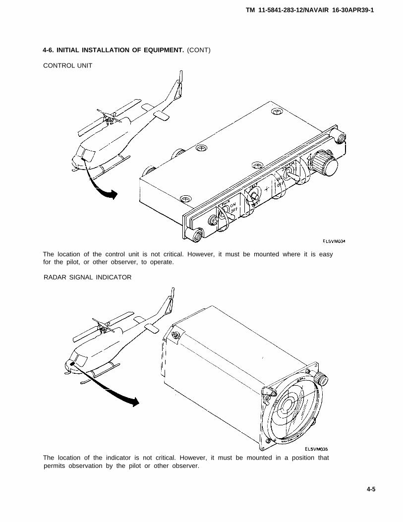
4-6. INITIAL INSTALLATION OF EQUIPMENT. (CONT)
CONTROL UNIT
The location of the control unit is not critical. However, it must be mounted where it is easyfor the pilot, or other observer, to operate.
RADAR SIGNAL INDICATOR
The location of the indicator is not critical. However, it must be mounted in a position thatpermits observation by the pilot or other observer.
4-5

TM 11-5841-283-12/NAVAIR 16-30APR39-1
4-6. INITIAL INSTALLATION OF EQUIPMENT.
COMPARATOR
(CONT)
The location of the comparator is not critical. However, it should be mounted in a positionwhere it can be easily removed.
4-6

TM 11-5841-283-12/NAVAIR 16-30APR39-1
4-6. INITIAL INSTALLATION OF EQUIPMENT. (CONT)
RADAR RECEIVERS
The radar receivers should be located in the aircraft so that the cables between the spiralantennas and the receivers are as short as possible.
The lengths of cable between the forward receiver and the forward left and forward rightantennas, and the lengths of cable between the aft receiver and the aft left and aft rightantennas must be as near the same length as possible. This will keep the signal strengthbetween the receivers and antennas the same.
The forward receiver should be located toward the front of the aircraft midway between the twoforward spiral antennas, and the aft receiver should be located toward the aft of the aircraftmidway between the two aft spiral antennas.
4-7
TM 11-5841-283-12/NAVAIR 16-30APR39-1
4-6. INITIAL INSTALLATION OF EQUIPMENT. (CONT)
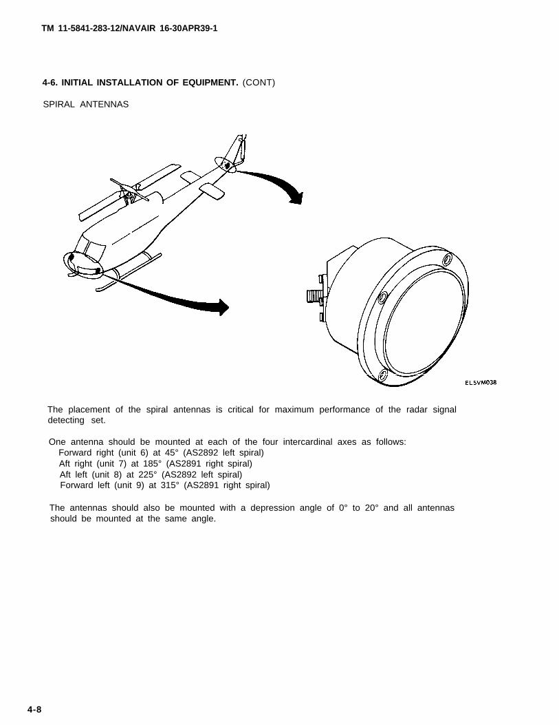
SPIRAL ANTENNAS
The placement of the spiral antennas is critical for maximum performance of the radar signaldetecting set.
One antenna should be mounted at each of the four intercardinal axes as follows:Forward right (unit 6) at 45° (AS2892 left spiral)Aft right (unit 7) at 185° (AS2891 right spiral)Aft left (unit 8) at 225° (AS2892 left spiral)Forward left (unit 9) at 315° (AS2891 right spiral)
The antennas should also be mounted with a depression angle of 0° to 20° and all antennasshould be mounted at the same angle.
4-8
TM 11-5841-283-12/NAVAIR 16-30APR39-1
4-6. INITIAL INSTALLATION OF EQUIPMENT. (CONT)
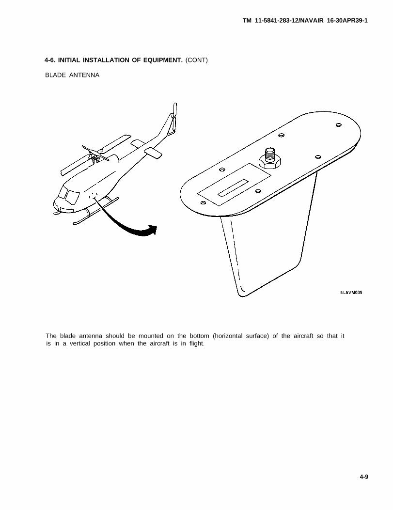
BLADE ANTENNA
The blade antenna should be mounted on the bottom (horizontal surface) of the aircraft so that itis in a vertical position when the aircraft is in flight.
4-9
TM 11-5841-283-12/NAVAIR 16-30APR39-1
4-7. TOOLS, TEST EQUIPMENT, AND MATERIALS REQUIRED FOR INITIAL INSTALLATION.
The tools, test equipment, and materials required for the initial installation of the radarsignal detecting set are shown in the Maintenance Allocation Chart listed in appendix B.
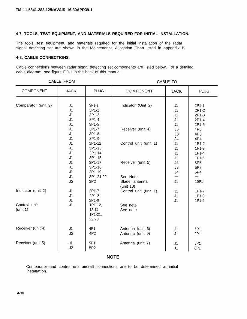
4-8. CABLE CONNECTIONS.
Cable connections between radar signal detecting set components are listed below. For a detailedcable diagram, see figure FO-1 in the back of this manual.
CABLE FROM CABLE TO
COMPONENT
Comparator (unit 3)
Indicator (unit 2)
Control unit(unit 1)
Receiver (unit 4)
Receiver (unit 5)
JACK
J1J1J1J1J1J1J1J1J1J1J1J1J1J1J1J1J2
J1J1J1J1
J1J2
J1J2
PLUG
3P1-13P1-23P1-33P1-43P1-53P1-73P1-83P1-93P1-123P1-133P1-143P1-153P1-173P1-183P1-193P1-21,223P2
2P1-72P1-82P1-91P1-12,13,141P1-21,22,23
4P14P2
5P15P2
COMPONENT
NOTE
Indicator (Unit 2)
Receiver (unit 4)
Control unit (unit 1)
Receiver (unit 5)
See NoteBlade antenna(unit 10)Control unit (unit 1)
See noteSee note
Antenna (unit 6)Antenna (unit 9)
Antenna (unit 7)
JACK
J1J1J1J1J1J5J3J4J1J1J1J1J5J3J4—J1
J1J1J1
J1J1
J1J1
PLUG
2P1-12P1-22P1-32P1-42P1-54P54P34P41P1-21P1-31P1-41P1-55P55P35P4—10P1
1P1-71P1-81P1-9
6P19P1
5P18P1
Comparator and control unit aircraft connections are to be determined at initialinstallation.
4-10
TM 11-5841-283-12/NAVAIR 16-30APR39-1
4-9. INSTALLATION OF PLUG-IN ITEMS.
Plug-in cards are contained in the comparator and receivers. No installation procedures are authorizedat the AVUM level.
4-10. PRELIMINARY SERVICING AND ADJUSTMENT OF EQUIPMENT.
Preliminary servicing and adjustment of the radar signal detecting set consists of a self-test andsystem function test.
SELF-TEST
Perform a self-test to make sure the radar signal detecting set equipment is working properly. Seeparagraph 2-4.
SYSTEM FUNCTION TEST
Perform the system function test to ensure system capability and circuit alinement. If you do not getthe indication required for any step, see Troubleshooting, chapter 4, section IV.
This task covers:
System function test of the radar signal detecting set.
INITIAL SETUP
Materials/Parts Equipment Condition
Headset Self-test completed and equipmentfully operational.
Personnel RequiredTest Equipment
Two techniciansRadar Signal Simulator SM-674/UPM
NSN 694-01-031-5887NOTE
See TM 11-6940-211-12 for operation instructions for the radar signal simulator.
4-11
4-10. PRELIMINARY SERVICING AND ADJUSTMENT OF EQUIPMENT. (CONT)
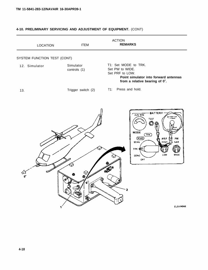
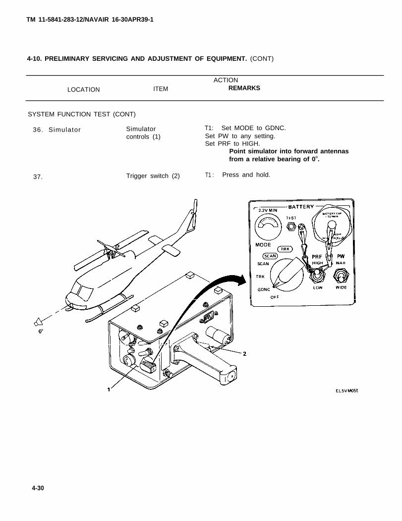
ACTIONLOCATION ITEM REMARKS
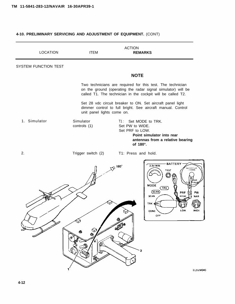
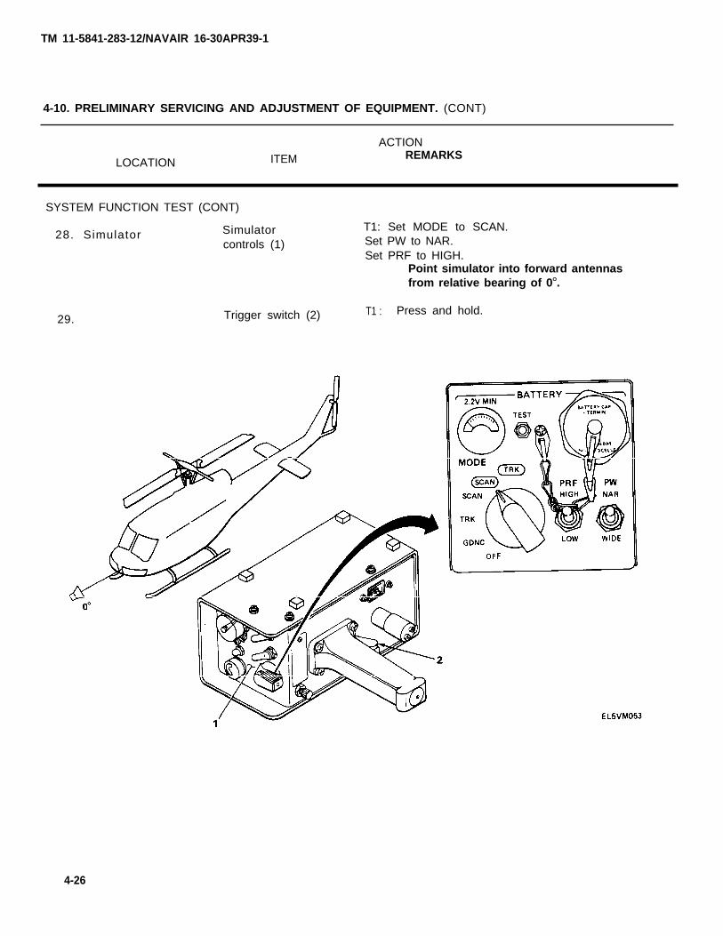
1. Simulator
2.
SYSTEM FUNCTION TEST
NOTE
Two technicians are required for this test. The technicianon the ground (operating the radar signal simulator) will becalled T1. The technician in the cockpit will be called T2.
Set 28 vdc circuit breaker to ON. Set aircraft panel lightdimmer control to full bright. See aircraft manual. Controlunit panel lights come on.
Simulator T1 : Set MODE to TRK.controls (1) Set PW to WIDE.
Set PRF to LOW.Point simulator into rearantennas from a relative bearingof 180°.
Trigger switch (2) T1: Press and hold.
4-12
TM 11-5841-283-12/NAVAIR 16-30APR39-1
TM 11-5841-283-12/NAVAIR 16-30APR39-1
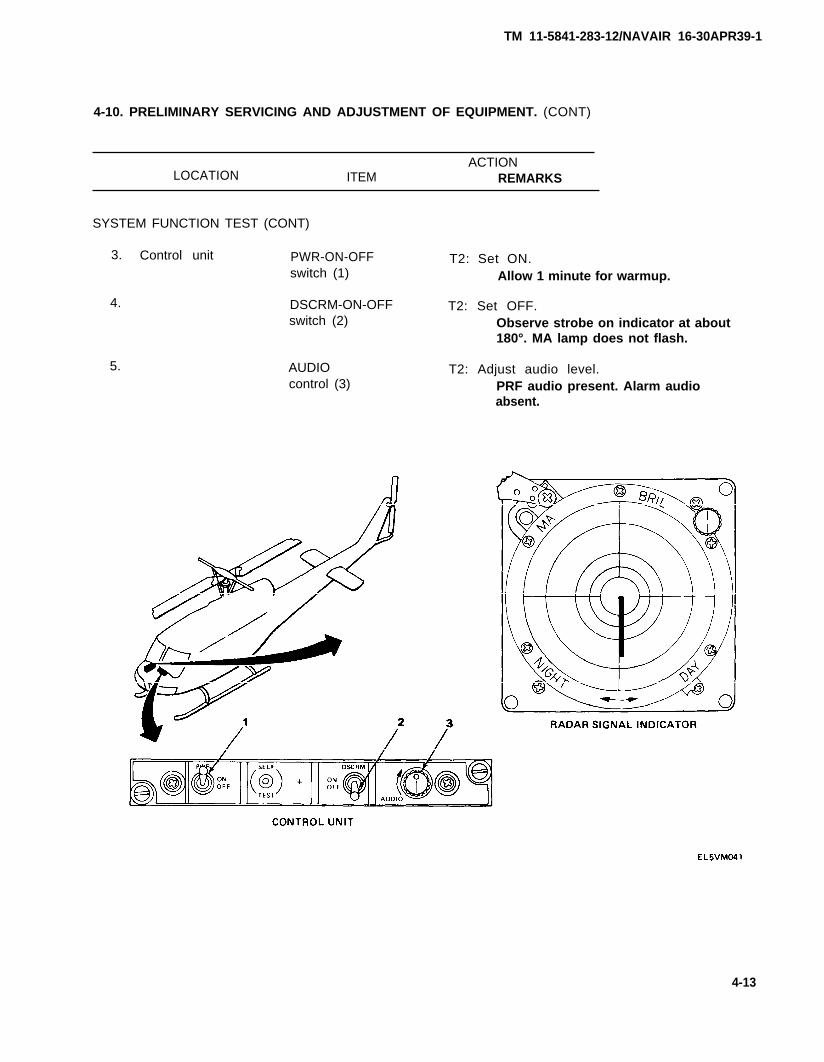
4-10. PRELIMINARY SERVICING AND ADJUSTMENT OF EQUIPMENT. (CONT)
ACTIONLOCATION ITEM REMARKS
SYSTEM FUNCTION TEST (CONT)
3.
4.
5.
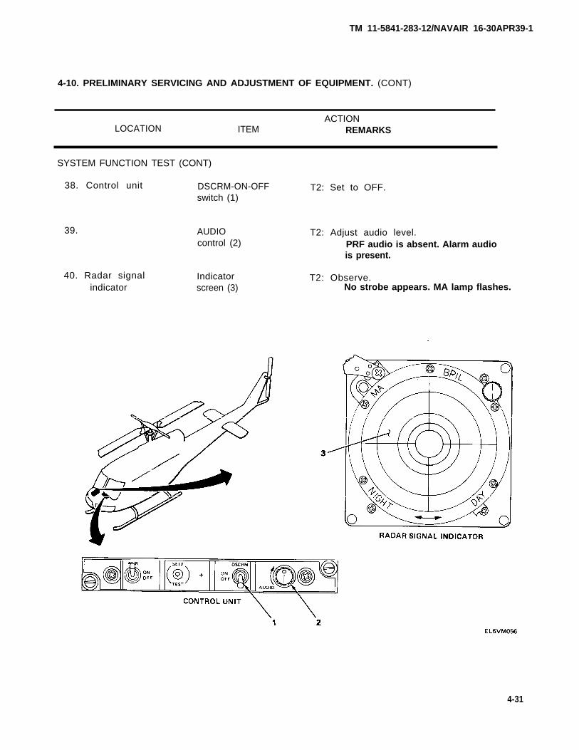
Control unit PWR-ON-OFFswitch (1)
DSCRM-ON-OFFswitch (2)
AUDIOcontrol (3)
T2: Set ON.Allow 1 minute for warmup.
T2: Set OFF.Observe strobe on indicator at about180°. MA lamp does not flash.
T2: Adjust audio level.PRF audio present. Alarm audioabsent.
4-13
TM 11-5841-283-12/NAVAIR 16-30APR39-1
4-10. PRELIMINARY SERVICING AND ADJUSTMENT OF EQUIPMENT. (CONT)
ACTIONLOCATION ITEM REMARKS
SYSTEM FUNCTION TEST (CONT)
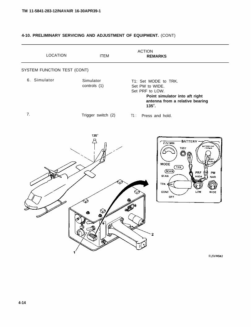
6. Simulator Simulatorcontrols (1)
7.
T1: Set MODE to TRK.Set PW to WIDE.Set PRF to LOW.
Point simulator into aft rightantenna from a relative bearing135O.
Trigger switch (2) T1 : Press and hold.
4-14

TM 11-5841-283-12/NAVAIR 16-30APR39-1
4-10. PRELIMINARY SERVICING AND ADJUSTMENT OF EQUIPMENT. (CONT)
ACTIONLOCATION ITEM REMARKS
SYSTEM FUNCTION TEST (CONT)
8. Radar signal Indicatorindicator screen (1)
T2: Observe.Strobe appears on indicator atabout 135°. PRF audio is heard.Alarm tone is absent. MA lampdoes not flash.
4-15

TM 11-5841-283-12/NAVAIR 16-30APR39-1
4-10. PRELIMINARY SERVICING AND ADJUSTMENT OF EQUIPMENT. (CONT)
ACTIONLOCATION ITEM REMARKS
SYSTEM FUNCTION TEST (CONT)
9. Simulator Simulatorcontrols (1)
10. Trigger switch (2)
T1: Set MODE to TRK.Set PW to WIDE.Set PRF to LOW.
Point simulator into forward rightantenna from a relative bearing of 45°.
T1: Press and hold.
4-16
TM 11-5841-283-12/NAVAIR 16-30APR39-1
4-10. PRELIMINARY SERVICING AND ADJUSTMENT OF EQUIPMENT. (CONT)
ACTIONLOCATION ITEM REMARKS
SYSTEM FUNCTION TEST (CONT)
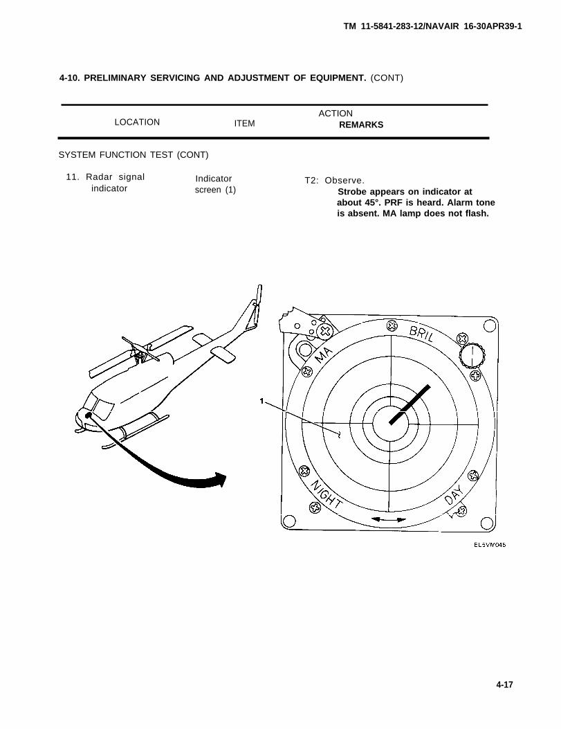
11. Radar signal Indicatorindicator screen (1)
T2: Observe.Strobe appears on indicator atabout 45°. PRF is heard. Alarm toneis absent. MA lamp does not flash.
4-17
TM 11-5841-283-12/NAVAIR 16-30APR39-1
4-10. PRELIMINARY SERVICING AND ADJUSTMENT OF EQUIPMENT. (CONT)
ACTION
LOCATION ITEM REMARKS
SYSTEM FUNCTION TEST (CONT)
12. Simulator Simulatorcontrols (1)
13.
4-18
T1: Set MODE to TRK.Set PW to WIDE.Set PRF to LOW.
Point simulator into forward antennasfrom a relative bearing of 0O.
Trigger switch (2) T1: Press and hold.
TM 11-5841-283-12/NAVAIR 16-30APR39-1
4-10. PRELIMINARY SERVICING AND ADJUSTMENT OF EQUIPMENT. (CONT)
ACTIONLOCATION ITEM REMARKS
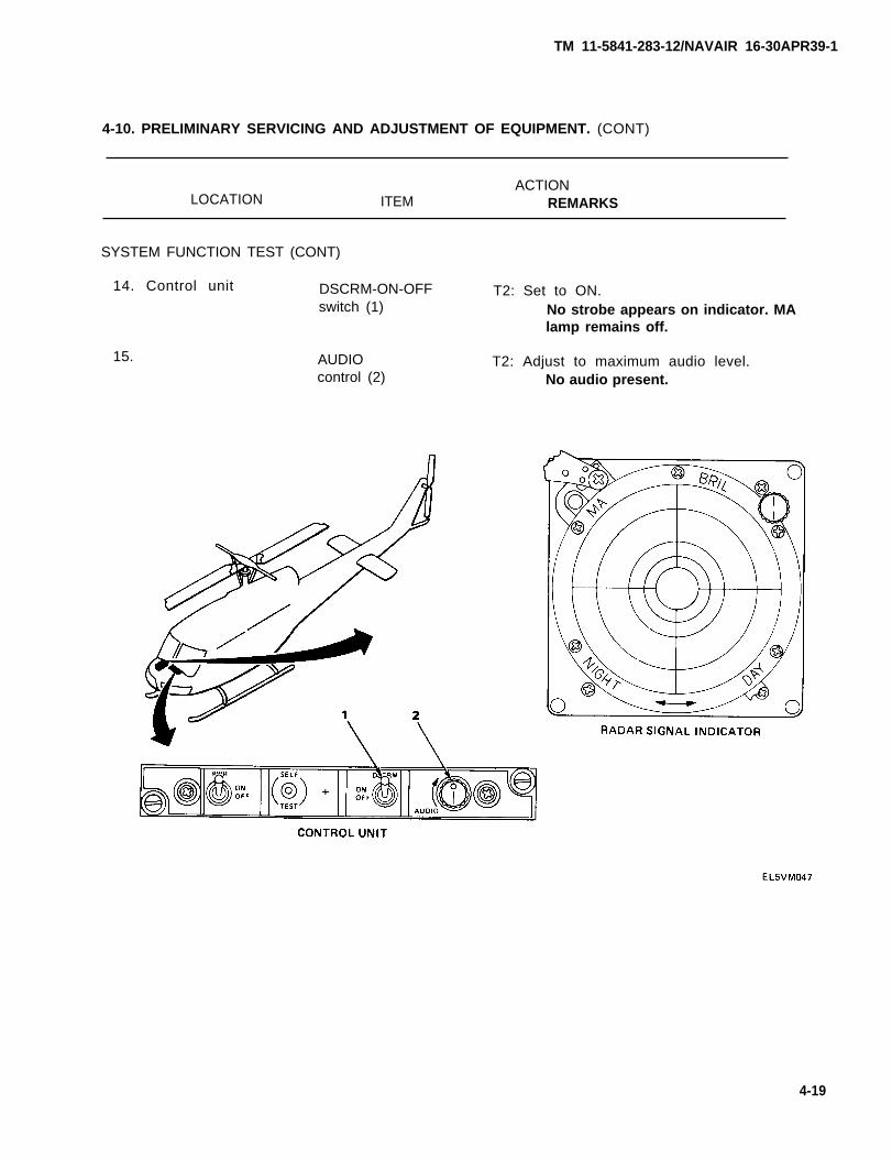
SYSTEM FUNCTION TEST (CONT)
14. Control unit DSCRM-ON-OFFswitch (1)
15. AUDIOcontrol (2)
T2: Set to ON.No strobe appears on indicator. MAlamp remains off.
T2: Adjust to maximum audio level.No audio present.
4-19
TM 11-5841-283-12/NAVAIR 16-30APR39-1
4-10. PRELIMINARY SERVICING AND ADJUSTMENT OF EQUIPMENT. (CONT)
ACTION
LOCATION ITEM REMARKS
SYSTEM FUNCTION TEST (CONT)
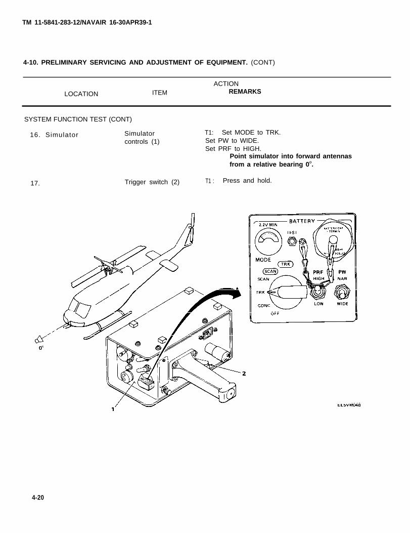
16. Simulator Simulatorcontrols (1)
17. Trigger switch (2)
T1: Set MODE to TRK.Set PW to WIDE.Set PRF to HIGH.
Point simulator into forward antennasfrom a relative bearing 0O.
T1 : Press and hold.
4-20
TM 11-5841-283-12/NAVAIR 16-30APR39-1
4-10. PRELIMINARY SERVICING AND ADJUSTMENT OF EQUIPMENT. (CONT)
ACTIONLOCATION ITEM REMARKS
SYSTEM FUNCTION TEST (CONT)
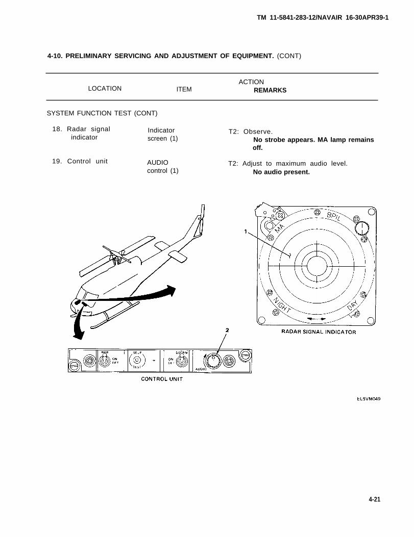
18. Radar signal Indicatorindicator screen (1)
19. Control unit AUDIOcontrol (1)
T2: Observe.No strobe appears. MA lamp remainsoff.
T2: Adjust to maximum audio level.No audio present.
4-21
TM 11-5841-283-12/NAVAIR 16-30APR39-1
4-10. PRELIMINARY SERVICING AND ADJUSTMENT OF EQUIPMENT. (CONT)
ACTIONLOCATION ITEM REMARKS
SYSTEM FUNCTION TEST (CONT)
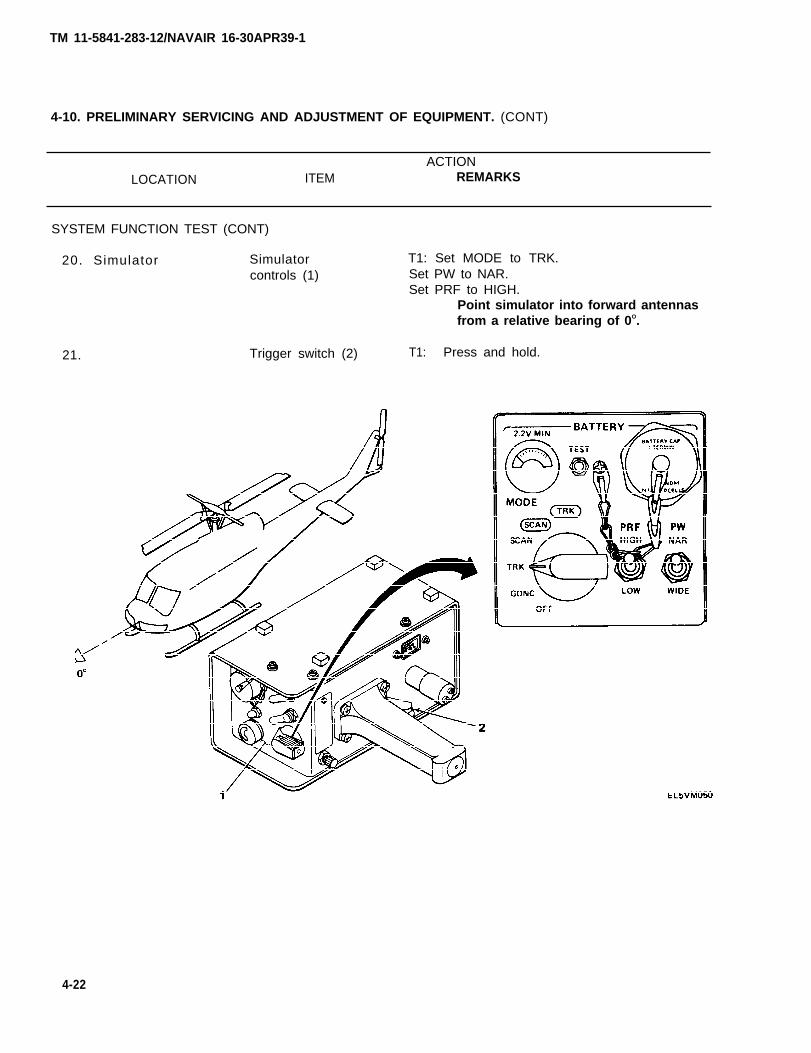
20. Simulator Simulatorcontrols (1)
21. Trigger switch (2)
T1: Set MODE to TRK.Set PW to NAR.Set PRF to HIGH.
Point simulator into forward antennasfrom a relative bearing of 0O.
T1: Press and hold.
4-22
TM 11-5841-283-12/NAVAIR 16-30APR39-1
4-10. PRELIMINARY SERVICING AND ADJUSTMENT OF EQUIPMENT. (CONT)
ACTIONLOCATION ITEM REMARKS
SYSTEM FUNCTION TEST (CONT)
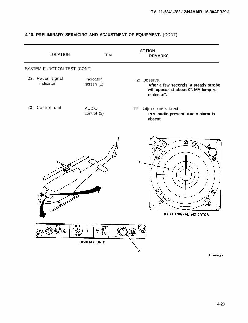
22. Radar signal Indicatorindicator screen (1)
23. Control unit AUDIOcontrol (2)
T2: Observe.After a few seconds, a steady strobewill appear at about 0O. MA lamp re-mains off.
T2: Adjust audio level.PRF audio present. Audio alarm isabsent.
4-23
TM 11-5841-283-12/NAVAIR 16-30APR39-1
4-10. PRELIMINARY SERVICING AND ADJUSTMENT OR EQUIPMENT. (CONT)
ACTION
LOCATION ITEM REMARKS
SYSTEM FUNCTION TEST (CONT)
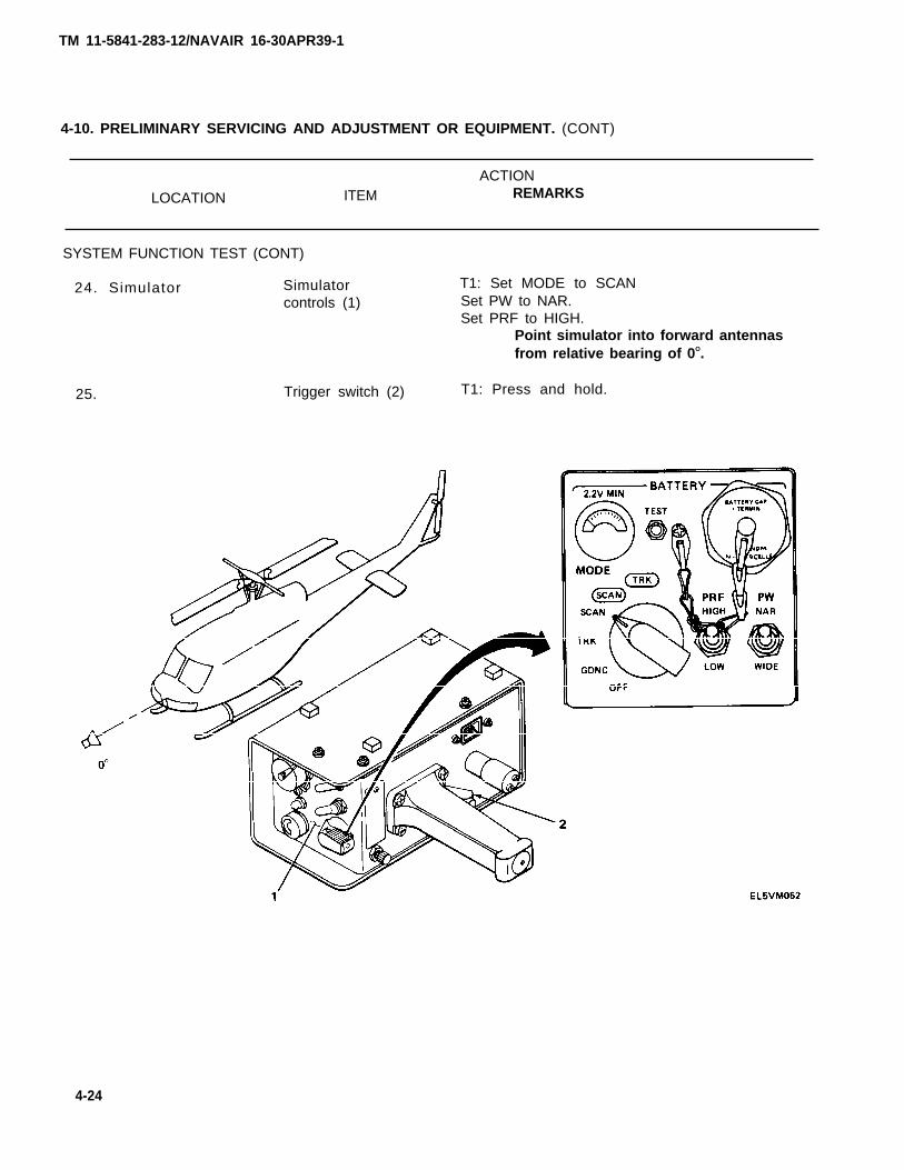
24. Simulator Simulatorcontrols (1)
25. Trigger switch (2)
T1: Set MODE to SCANSet PW to NAR.Set PRF to HIGH.
Point simulator into forward antennasfrom relative bearing of 0O.
T1: Press and hold.
4-24
TM 11-5841-283-12/NAVAIR 16-30APR39-1
4-10. PRELIMINARY SERVICING AND ADJUSTMENT OF EQUIPMENT. (CONT)
LOCATION ITEMACTION
REMARKS
SYSTEM FUNCTION TEST (CONT)
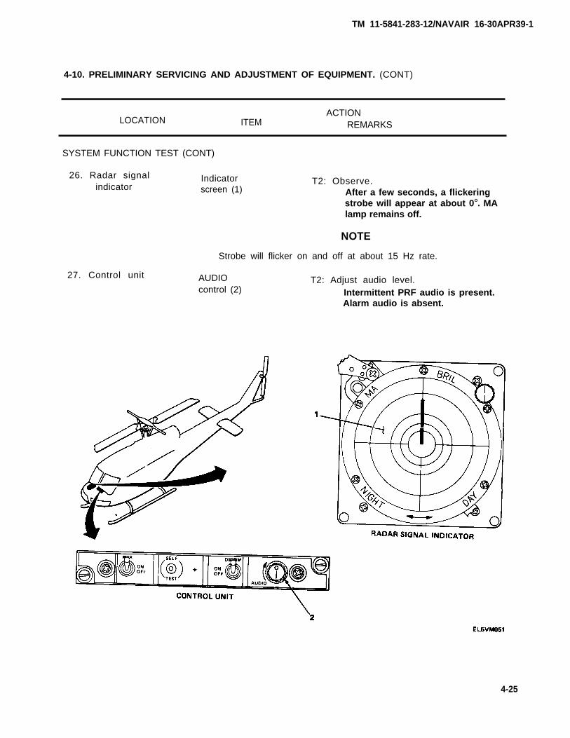
26. Radar signal Indicatorindicator screen (1)
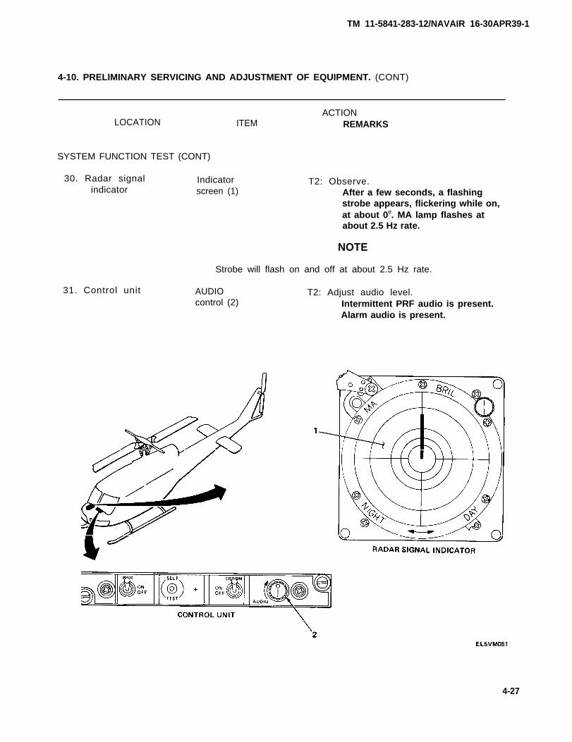
T2: Observe.After a few seconds, a flickeringstrobe will appear at about 0O. MAlamp remains off.
NOTE
Strobe will flicker on and off at about 15 Hz rate.
27. Control unit AUDIO T2: Adjust audio level.control (2) Intermittent PRF audio is present.
Alarm audio is absent.
4-25
TM 11-5841-283-12/NAVAlR 16-30APR39-1
4-10. PRELIMINARY SERVICING AND ADJUSTMENT OF EQUIPMENT. (CONT)
ACTION
LOCATION ITEM REMARKS
SYSTEM FUNCTION TEST (CONT)
28. Simulator Simulatorcontrols (1)
29. Trigger switch (2)
T1: Set MODE to SCAN.Set PW to NAR.Set PRF to HIGH.
Point simulator into forward antennasfrom relative bearing of 0O.
T1 : Press and hold.
4-26
TM 11-5841-283-12/NAVAIR 16-30APR39-1
4-10. PRELIMINARY SERVICING AND ADJUSTMENT OF EQUIPMENT. (CONT)
ACTIONLOCATION ITEM REMARKS
SYSTEM FUNCTION TEST (CONT)
30. Radar signal Indicatorindicator screen (1)
31. Control unit
T2: Observe.After a few seconds, a flashingstrobe appears, flickering while on,at about 0O. MA lamp flashes atabout 2.5 Hz rate.
NOTE
Strobe will flash on and off at about 2.5 Hz rate.
AUDIO T2: Adjust audio level.control (2) Intermittent PRF audio is present.
Alarm audio is present.
4-27
TM 11-5841-283-12/NAVAIR 16-30APR39-1
4-10. PRELIMINARY SERVICING AND ADJUSTMENT OF EQUIPMENT. (CONT)
ACTION
LOCATION ITEM REMARKS
SYSTEM FUNCTION TEST (CONT)
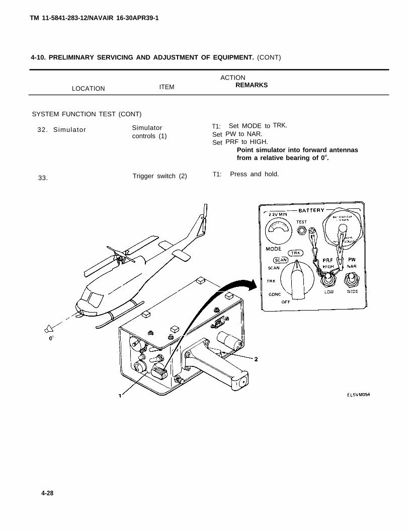
32. Simulator Simulator T1:
controls (1) SetSet
33. Trigger switch (2) T1:
Set MODE toPW to NAR.PRF to HIGH.
TRK.
Point simulator into forward antennasfrom a relative bearing of 0O.
Press and hold.
4-28
TM 11-5841-283-12/NAVAIR 16-30APR39-1
4-10. PRELIMINARY SERVICING AND ADJUSTMENT OF EQUIPMENT. (CONT)
ACTIONLOCATION ITEM REMARKS
SYSTEM FUNCTION TEST (CONT)
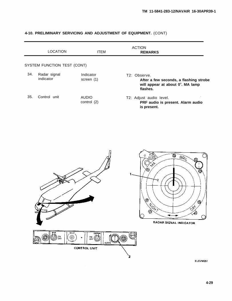
34.
35.
Radar signal Indicatorindicator screen (1)
Control unit AUDIOcontrol (2)
T2: Observe.After a few seconds, a flashing strobewill appear at about 0O. MA lampflashes.
T2: Adjust audio Ievel..
PRF audio is present. Alarm audiois present.
4-29
TM 11-5841-283-12/NAVAIR 16-30APR39-1
4-10. PRELIMINARY SERVICING AND ADJUSTMENT OF EQUIPMENT. (CONT)
ACTION
LOCATION ITEM REMARKS
SYSTEM FUNCTION TEST (CONT)
36. Simulator Simulatorcontrols (1)
37. Trigger switch (2)
T1: Set MODE to GDNC.Set PW to any setting.Set PRF to HIGH.
Point simulator into forward antennasfrom a relative bearing of 0O.
T1 : Press and hold.
4-30
TM 11-5841-283-12/NAVAIR 16-30APR39-1
4-10. PRELIMINARY SERVICING AND ADJUSTMENT OF EQUIPMENT. (CONT)
ACTIONLOCATION ITEM REMARKS
SYSTEM FUNCTION TEST (CONT)
38. Control unit DSCRM-ON-OFFswitch (1)
39.
40. Radar signalindicator
AUDIOcontrol (2)
Indicatorscreen (3)
T2: Set to OFF.
T2: Adjust audio level.PRF audio is absent. Alarm audiois present.
T2: Observe.No strobe appears. MA lamp flashes.
4-31
TM 11-5841-283-12/NAVAIR 16-30APR39-1
4-10. PRELIMINARY SERVICING AND ADJUSTMENT OF EQUIPMENT. (CONT)
ACTION
LOCATION ITEM REMARKS
SYSTEM FUNCTION (CONT)
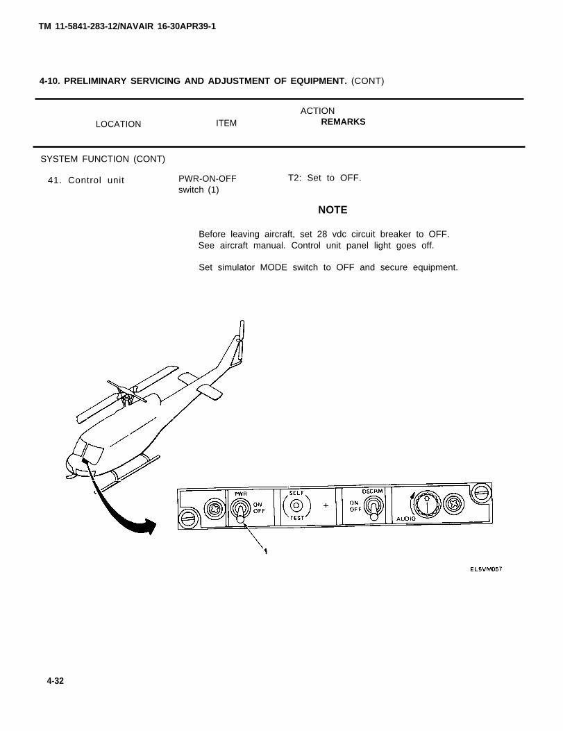
41. Control unit PWR-ON-OFF T2: Set to OFF.switch (1)
NOTE
Before leaving aircraft, set 28 vdc circuit breaker to OFF.See aircraft manual. Control unit panel light goes off.
Set simulator MODE switch to OFF and secure equipment.
4-32

TM 11-5841-283-12/NAVAIR 16-30APR39-1
Section III AVIATION UNIT PREVENTIVE MAINTENANCE CHECKS AND SERVICES
Subject Page
Overview . . . . . . . . . . . . . . . . . . . . . . . . . . . . . . . . . . . . . . . . . . . . . . . . . . . . . . . . . . . . . 4-33PMCS Procedures . . . . . . . . . . . . . . . . . . . . . . . . . . . . . . . . . . . . . . . . . . . . . . . . . . . . . 4-34
OVERVIEW
To be sure that the radar signal detecting set is always ready, aviation unit maintenance mustperform Preventive Maintenance Checks and Services (PMCS).
Perform aviation unit level PMCS on a monthly (M) basis. A month is 30 calendar days for an8 hour per day operation. If the equipment is operated 24 hours per day, the M PMCS shouldbe performed every 10 days.
PMCS TABLE
The item No. column is used as a source for the TM number on DA Form 2404.
The ltem to be lnspected column describes the equipment or parts of the radar signal detectingset that must be inspected. Inspect all items listed.
The Procedures column describes how to perform the needed checks and services. Followinstructions carefully.
If any problems arise during PMCS, or if you find any damage, refer to the aviation unittroubleshooting section in this manual for instructions to correct it. A higher level of main-tenance may be required.
NOTE
Always keep in mind the Cautions and Warnings.
4-33

TM 11-5841-283-12/NAVAIR 16-30APR39-1
ITEMNO.
1
AVIATION UNIT PREVENTIVE MAINTENANCE CHECKS AND SERVICES
M - MONTHLY
INTERVAL
MITEM TO BEINSPECTED PROCEDURE
CAUTION
Before performing PMCS, set 28 vdc circuit breaker to OFF.
Control Unit Remove control unit from instrumentpanel. See paragraph 4-15.
Clean exterior surfaces of control unitand cable connections. Check for rustor corrosion. See paragraph 4-11.
Repair any frayed or bare wires.Repair damaged connector pins.
Replace fasteners that are broken,stripped, or corroded.
Replace spare fuse, if missing.
Install control unit in instrumentpanel. See paragraph 4-15.
4-34
TM 11-5841-283-12/NAVAIR 16-30APR39-1
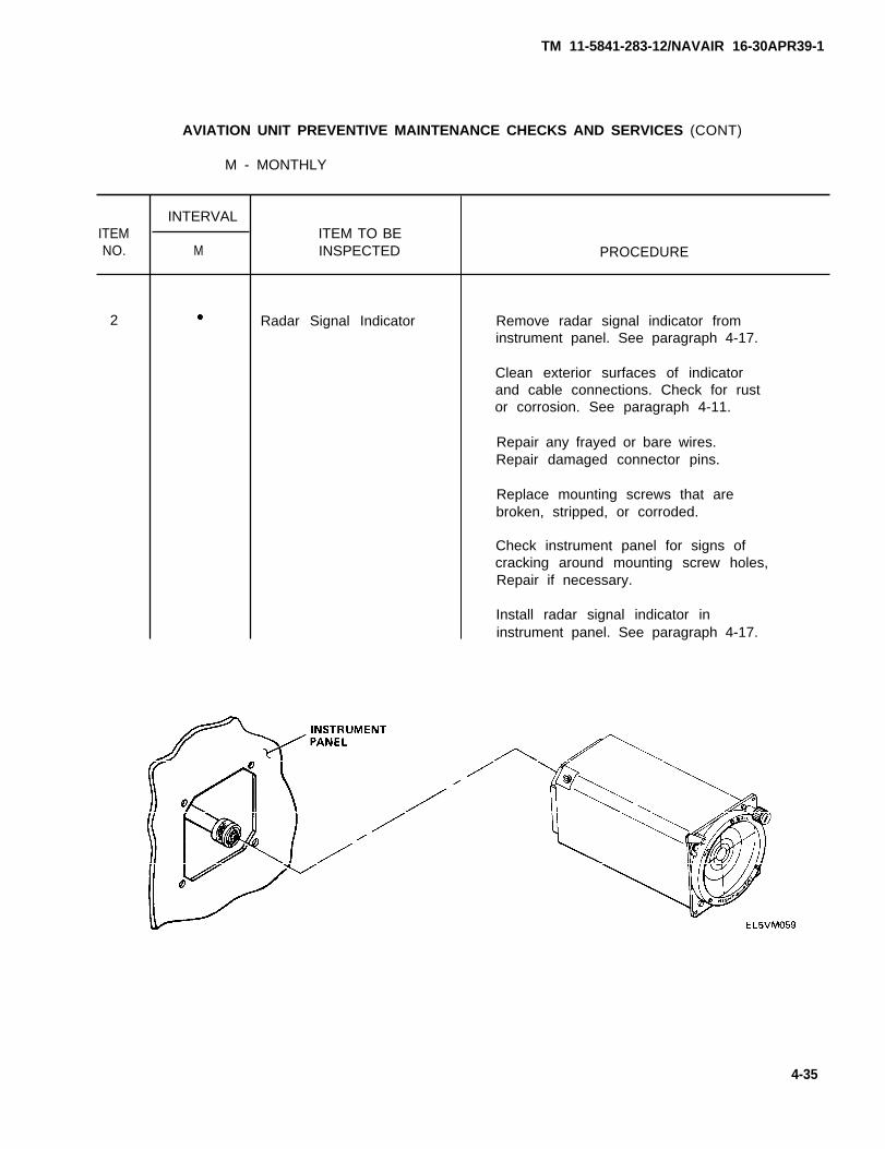
ITEMNO.
2
AVIATION UNIT PREVENTIVE MAINTENANCE CHECKS AND SERVICES (CONT)
M - MONTHLY
INTERVAL
MITEM TO BEINSPECTED
Radar Signal Indicator
PROCEDURE
Remove radar signal indicator frominstrument panel. See paragraph 4-17.
Clean exterior surfaces of indicatorand cable connections. Check for rustor corrosion. See paragraph 4-11.
Repair any frayed or bare wires.Repair damaged connector pins.
Replace mounting screws that arebroken, stripped, or corroded.
Check instrument panel for signs ofcracking around mounting screw holes,Repair if necessary.
Install radar signal indicator ininstrument panel. See paragraph 4-17.
4-35
TM 11-5841-283-12/NAVAIR 16-30APR39-1
AVIATION UNIT PREVENTIVE MAINTENANCE CHECKS AND SERVICES (CONT)
M - MONTHLY
ITEMNO.
3
4-36
INTERVAL
MITEM TO BEINSPECTED
Comparator
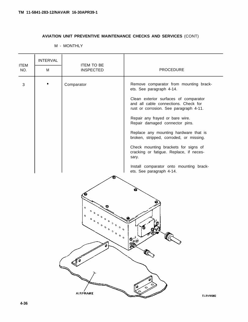
PROCEDURE
Remove comparator from mounting brack-ets. See paragraph 4-14.
Clean exterior surfaces of comparatorand all cable connections. Check forrust or corrosion. See paragraph 4-11.
Repair any frayed or bare wire.Repair damaged connector pins.
Replace any mounting hardware that isbroken, stripped, corroded, or missing.
Check mounting brackets for signs ofcracking or fatigue. Replace, if neces-sary.
Install comparator onto mounting brack-ets. See paragraph 4-14.

ITEMNO.
4
TM 11-5841-283-12/NAVAIR 16-30APR39-1
AVIATION UNIT PREVENTIVE MAINTENANCE CHECKS AND SERVICES (CONT)
M - MONTHLY
INTERVAL
MITEM TO BEINSPECTED
Radar Receivers
PROCEDURE
Remove the forward and aft radar re-ceivers from the aircraft airframe.See paragraph 4-16.
Clean exterior surfaces of each re-ceiver and all cable connections.Check for rust or corrosion. Seeparagraph 4-11.
Repair any frayed or bare wire.Repair damaged connector pins,
Replace any mounting hardware that isbroken, stripped, corroded, or missing.
Check airframe around mounting screwholes for signs of cracking. Repair, ifnecessary.
Install the forward and aft radar re-ceivers onto the aircraft airframe. Seeparagraph 4-16.
4-37
TM 11-5841-283-12/NAVAIR 16-30APR39-1
AVIATION UNIT PREVENTIVE MAINTENANCE CHECKS AND SERVICES (CONT)
M - MONTHLY
ITEMNO.
5
INTERVAL
MITEM TO BEINSPECTED
Spiral Antennas
PROCEDURE
Remove all four spiral antennas. Seeparagraph 4-18.
Clean radome of each antenna and cableconnectors. Check for rust or corrosion.See paragraph 4-11.
Check radome for cracks or signs ofdeterioration. Replace antenna ifnecessary.
Replace gasket if damaged.
NOTE
Some aircraft may not use agasket.
Repair any frayed or bare wire.Repair damaged connector pins.
Replace any screws that are broken,stripped, corroded, or missing.
Check airframe around mounting screwholes for signs of cracking. Repair, ifnecessary.
NOTE
Use clear sealant around antennacontact surface to prevent waterleakage.
Install all four spiral antennas. Seeparagraph 4-18.
4-38

TM 11-5841-283-12/NAVAIR 16-30APR39-1
ITEMNO.
6
AVIATION UNIT PREVENTIVE MAINTENANCE CHECKS AND SERVICES (CONT)
M - MONTHLY
INTERVAL
MITEM TO BEINSPECTED
Blade Antenna
PROCEDURE
Remove blade antenna from airframe, Seeparagraph 4-13.
Clean exterior surfaces and all cableconnections. Check for rust or cor-rosion. See paragraph 4-11.
Repair any frayed or bare wire.Repair damaged connector pins.
Replace any screws that are broken,stripped, corroded, or missing.
Check airframe around mounting screwholes for signs of cracking. Repair, ifnecessary.
NOTE
Use clear sealant around antennacontact surface to prevent waterleakage.
Install blade antenna onto airframe.See paragraph 4-13.
4-39
ITEMNO.
7
8
9
AVIATION UNIT PREVENTIVE MAINTENANCE CHECKS AND SERVICES (CONT)
M - MONTHLY
INTERVAL
MITEM TO BEINSPECTED
Radar Signal Detecting Set
End Item List
Modification Work Orders(MWO's)
PROCEDURE
Perform a system function test. Seeparagraph 4-10.
Check that all equipment on the EndItem List has all parts and spares.Check that all equipment is mounted orstored in proper place.
Check that all MWO’s are done and MWO’sare stamped. All urgent MWO’s must bedone at once, and all normal MWO’sscheduled.
4-40
TM 11-5841-283-12/NAVAIR 16-30APR39-1
Section IV AVIATION UNIT TROUBLESHOOTING
Subject
Overview . . . . . . . . . . . . . . . . . . . . . . . . . . . . . . . . . . . . . . . . . . . . . . . . . . . . . . . . . . . . .Symptom Index . . . . . . . . . . . . . . . . . . . . . . . . . . . . . . . . . . . . . . . . . . . . . . . . . . . . . . .Troubleshooting . . . . . . . . . . . . . . . . . . . . . . . . . . . . . . . . . . . . . . . . . . . . . . . . . . . . . . .
OVERVIEW
The troubleshooting table Iists problems that you may find when operating the radar signaldetecting set equipment or when doing the PMCS.
The troubleshooting table does not list all of the problems which you may find. If your problemis not listed, report it to your supervisor. If the troubleshooting steps do not solve yourproblem, report it to your supervisor. When working on any problem, be sure to report yourwork on the forms shown in TM 38-750.
To use the troubleshooting table, first find your problem in the symptom index. The symptomindex is organized by component and problems for each component. The index will give you a pagenumber on which you will find your problem and the possible corrections. Turn to that page, findyour problem, and use the procedures shown to correct it.
SYMPTOM INDEX
The symptom index lists problems that may be found while performing the system function test.
RADAR SIGNAL INDICATORNo indicator strobe and no audio present . . . . . . . . . . . . . . . . . . . . . . . . . . . . . . . . . . . . . . . . . . . .No indicator strobe and only MA audio Present . . . . . . . . . . . . . . . . . . . . . . . . . . . . . . . . . . . . . . .NO indicator strobe and all audio present. . . . . . . . . . . . . . . . . . . . . . . . . . . . . . . . . . . . . . . . . . . .MA lamp does not flash and no MA audio present. . . . . . . . . . . . . . . . . . . . . . . . . . . . . . . . . . . . . .MA lamp flashes only when SELF TEST button is released. . . . . . . . . . . . . . . . . . . . . . . . . . . . . .Upper half of indicator strobe is missing or shorter and
bends to right or left . . . . . . . . . . . . . . . . . . . . . . . . . . . . . . . . . . . . . . . . . . . . . . . . . . . . . . . . . . . . .Lower half of indicator strobe is missing or shorter andbends to right or left . . . . . . . . . . . . . . . . . . . . . . . . . . . . . . . . . . . . . . . . . . . . . . . . . . . . . . . . . . . . .
MA Iamp does not flash, but MA audio is heard . . . . . . . . . . . . . . . . . . . . . . . . . . . . . . . . . . . . . . . .
SPIRAL ANTENNASNot transmitting signal image (strobe) to indicator or signal
image is weak . . . . . . . . . . . . . . . . . . . . . . . . . . . . . . . . . . . . . . . . . . . . . . . . . . . . . . . . . . . . . . . . . .
Page
4-414-414-42
Page
4-424-424-424-434-43
4-43
4-434-43
4-44
4-41
TM 11-5841-283-12/NAVAIR 16-30APR39-1
TM 11-5841-283-12/NAVAIR 16-30APR39-1
TROUBLESHOOTING.
MALFUNCTIONTEST OR INSPECTION
CORRECTIVE ACTION
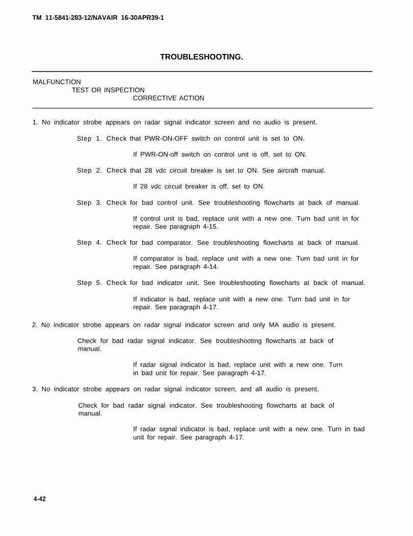
1. No indicator strobe appears on radar signal indicator screen and no audio is present.
Step 1. Check
Step 2. Check
Step 3. Check
Step 4. Check
Step 5. Check
that PWR-ON-OFF switch on control unit is set to ON.
If PWR-ON-off switch on control unit is off, set to ON.
that 28 vdc circuit breaker is set to ON. See aircraft manual.
If 28 vdc circuit breaker is off, set to ON.
for bad control unit. See troubleshooting flowcharts at back of manual.
If control unit is bad, replace unit with a new one. Turn bad unit in forrepair. See paragraph 4-15.
for bad comparator. See troubleshooting flowcharts at back of manual.
If comparator is bad, replace unit with a new one. Turn bad unit in forrepair. See paragraph 4-14.
for bad indicator unit. See troubleshooting flowcharts at back of manual.
If indicator is bad, replace unit with a new one. Turn bad unit in forrepair. See paragraph 4-17.
2. No indicator strobe appears on radar signal indicator screen and only MA audio is present.
Check for bad radar signal indicator. See troubleshooting flowcharts at back ofmanual.
If radar signal indicator is bad, replace unit with a new one. Turnin bad unit for repair. See paragraph 4-17.
3. No indicator strobe appears on radar signal indicator screen, and all audio is present.
Check for bad radar signal indicator. See troubleshooting flowcharts at back ofmanual.
If radar signal indicator is bad, replace unit with a new one. Turn in badunit for repair. See paragraph 4-17.
4-42
TM 11-5841-283-12/NAVAIR 16-30APR39-1
TROUBLESHOOTING.
MALFUNCTIONTEST OR INSPECTION
CORRECTIVE ACTION
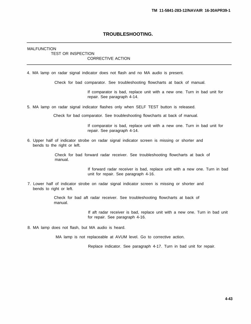
4. MA lamp on radar signal indicator does not flash and no MA audio is present.
Check for bad comparator. See troubleshooting flowcharts at back of manual.
If comparator is bad, replace unit with a new one. Turn in bad unit forrepair. See paragraph 4-14.
5. MA lamp on radar signal indicator flashes only when SELF TEST button is released.
Check for bad comparator. See troubleshooting flowcharts at back of manual.
If comparator is bad, replace unit with a new one. Turn in bad unit forrepair. See paragraph 4-14.
6. Upper half of indicator strobe on radar signal indicator screen is missing or shorter andbends to the right or left.
Check for bad forward radar receiver. See troubleshooting flowcharts at back ofmanual.
If forward radar receiver is bad, replace unit with a new one. Turn in badunit for repair. See paragraph 4-16.
7. Lower half of indicator strobe on radar signal indicator screen is missing or shorter andbends to right or left.
Check for bad aft radar receiver. See troubleshooting flowcharts at back ofmanual.
If aft radar receiver is bad, replace unit with a new one. Turn in bad unitfor repair. See paragraph 4-16.
8. MA lamp does not flash, but MA audio is heard.
MA lamp is not replaceable at AVUM level. Go to corrective action.
Replace indicator. See paragraph 4-17. Turn in bad unit for repair.
4-43
TM 11-5841-283-12/NAVAIR 16-30APR39-1
TROUBLESHOOTING.
MALFUNCTIONTEST OR INSPECTION
CORRECTIVE ACTION
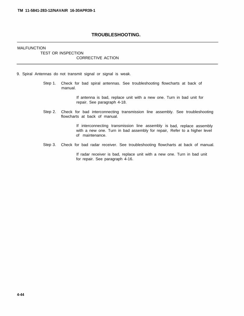
9. Spiral Antennas do
Step 1.
Step 2.
Step 3.
not transmit signal or signal is weak.
Check for bad spiral antennas. See troubleshooting flowcharts at back ofmanual.
If antenna is bad, replace unit with a new one. Turn in bad unit forrepair. See paragraph 4-18.
Check for bad interconnecting transmission line assembly. See troubleshootingflowcharts at back of manual.
If interconnecting transmission line assembly iswith a new one. Turn in bad assembly for repair,of maintenance.
bad, replace assemblyRefer to a higher level
Check for bad radar receiver. See troubleshooting flowcharts at back of manual.
If radar receiver is bad, replace unit with a new one. Turn in bad unitfor repair. See paragraph 4-16.
4-44
TM 11-5841-283-12/NAVAIR 16-30APR39-1
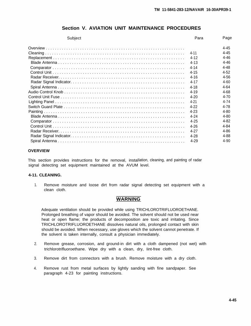
Section V. AVIATION UNIT MAINTENANCE PROCEDURES
Subject
Overview . . . . . . . . . . . . . . . . . . . . . . . . . . . . . . . . . . . . . . . . . . . . . . . . . . . . . . . . . . . . .Cleaning . . . . . . . . . . . . . . . . . . . . . . . . . . . . . . . . . . . . . . . . . . . . . . . . . . . . . . . . . . . . .Replacement . . . . . . . . . . . . . . . . . . . . . . . . . . . . . . . . . . . . . . . . . . . . . . . . . . . . . . . . .
Blade Antenna . . . . . . . . . . . . . . . . . . . . . . . . . . . . . . . . . . . . . . . . . . . . . . . . . . . . . . .Comparator . . . . . . . . . . . . . . . . . . . . . . . . . . . . . . . . . . . . . . . . . . . . . . . . . . . . . . . . .Control Unit . . . . . . . . . . . . . . . . . . . . . . . . . . . . . . . . . . . . . . . . . . . . . . . . . . . . . . . . .Radar Receiver. . . . . . . . . . . . . . . . . . . . . . . . . . . . . . . . . . . . . . . . . . . . . . . . . . . . . . .Radar Signal Indicator. . . . . . . . . . . . . . . . . . . . . . . . . . . . . . . . . . . . . . . . . . . . . . . . .Spiral Antenna . . . . . . . . . . . . . . . . . . . . . . . . . . . . . . . . . . . . . . . . . . . . . . . . . . . . . . .
Audio Control Knob . . . . . . . . . . . . . . . . . . . . . . . . . . . . . . . . . . . . . . . . . . . . . . . . . . . .Control Unit Fuse . . . . . . . . . . . . . . . . . . . . . . . . . . . . . . . . . . . . . . . . . . . . . . . . . . . . . .Lighting Panel . . . . . . . . . . . . . . . . . . . . . . . . . . . . . . . . . . . . . . . . . . . . . . . . . . . . . . . .Switch Guard Plate . . . . . . . . . . . . . . . . . . . . . . . . . . . . . . . . . . . . . . . . . . . . . . . . . . . .Painting . . . . . . . . . . . . . . . . . . . . . . . . . . . . . . . . . . . . . . . . . . . . . . . . . . . . . . . . . . . . .
Blade Antenna . . . . . . . . . . . . . . . . . . . . . . . . . . . . . . . . . . . . . . . . . . . . . . . . . . . . . . .Comparator . . . . . . . . . . . . . . . . . . . . . . . . . . . . . . . . . . . . . . . . . . . . . . . . . . . . . . . . .Control Unit . . . . . . . . . . . . . . . . . . . . . . . . . . . . . . . . . . . . . . . . . . . . . . . . . . . . . . . . .Radar Receiver. . . . . . . . . . . . . . . . . . . . . . . . . . . . . . . . . . . . . . . . . . . . . . . . . . . . . . .Radar Signal Indicator. . . . . . . . . . . . . . . . . . . . . . . . . . . . . . . . . . . . . . . . . . . . . . . . .Spiral Antenna . . . . . . . . . . . . . . . . . . . . . . . . . . . . . . . . . . .
OVERVIEW
This section provides instructions for the removal, instalsignal detecting set equipment maintained at the AVUM
4-11. CLEANING.
. . . . . . . . . . . . . . . . . . . .
Para
4-114-124-134-144-154-164-174-184-194-204-214-224-234-244-254-264-274-284-29
level.
1. Remove moisture and Ioose dirt from radar signal detecting set equipment with aclean cloth.
WARNING
Adequate ventilation should be provided while using TRICHLOROTRIFLUOROETHANE.Prolonged breathing of vapor should be avoided. The solvent should not be used nearheat or open flame; the products of decomposition are toxic and irritating. SinceTRICHLOROTRIFLUOROETHANE dissolves natural oils, prolonged contact with skinshould be avoided. When necessary, use gloves which the solvent cannot penetrate. Ifthe solvent is taken internally, consult a physician immediately.
2. Remove grease, corrosion, and ground-in dirt with a cloth dampened (not wet) withtrichlorotrifluoroethane. Wipe dry with a clean, dry, Iint-free cloth.
3. Remove dirt from connectors with a brush. Remove moisture with a dry cloth.
4. Remove rust from metal surfaces by lightly sanding with fine sandpaper. Seeparagraph 4-23 for painting instructions.
Page
4-454-454-464-464-484-524-564-604-644-684-704-744-784-804-804-824-844-864-884-90
4-45
lation, cleaning, and painting of radar
TM 11-5841-283-12/NAVAIR 16-30APR39-1
4-12. REPLACEMENT.
Replacement instructions include removal and installation procedures for the followingequipment:
Blade antenna Spiral antennasComparator Audio control knobControl unit Control unit fuseRadar signal indicator Lighting panelReceivers Switch guard plate
After installing any repaired or new unit of the radar signal detecting set covered inparagraphs 4-13 thru 4-22, perform a self-test and a system function test.
4-13. BLADE ANTENNA REPLACEMENT.
This task covers:
1. Removal2. Installation
INITIAL SETUP
Tools Personnel Required
Tool, Kit, Electronic Equipment TK-101/G One technician
Materials/Parts Equipment Condition
Blade antenna NSN 5985-01-026-3927 28 vdc circuit breakerSee aircraft manual.
set OFF.
ACTIONLOCATION ITEM REMARKS
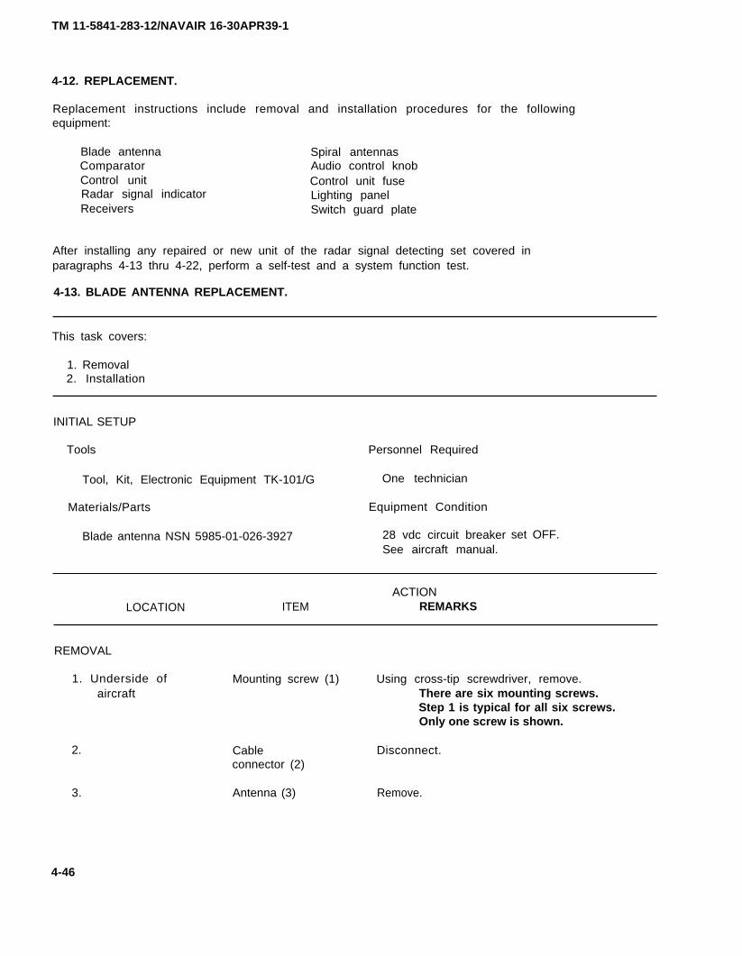
REMOVAL
1. Underside of Mounting screw (1) Using cross-tip screwdriver, remove.aircraft There are six mounting screws.
Step 1 is typical for all six screws.Only one screw is shown.
2. Disconnect.
3. Remove.
Cableconnector (2)
Antenna (3)
4-46
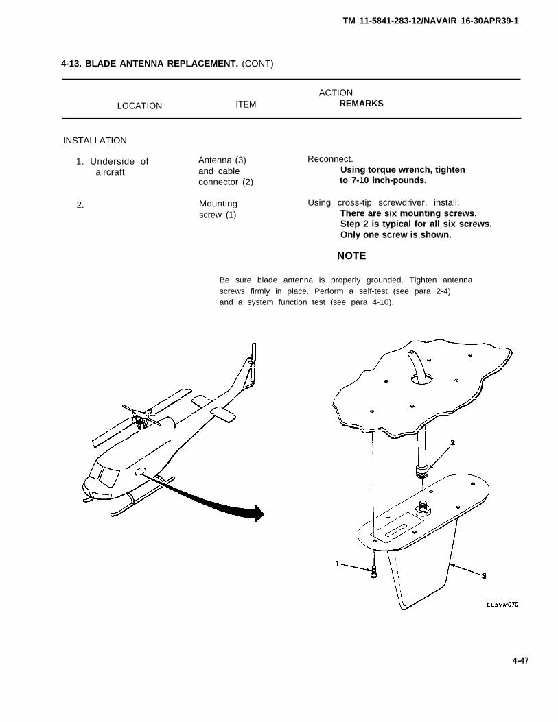
TM 11-5841-283-12/NAVAIR 16-30APR39-1
4-13. BLADE ANTENNA REPLACEMENT. (CONT)
ACTION
LOCATION ITEM REMARKS
INSTALLATION
1. Underside ofaircraft
2.
Antenna (3)and cableconnector (2)
Mountingscrew (1)
Reconnect.Using torque wrench, tightento 7-10 inch-pounds.
Using cross-tip screwdriver, install.There are six mounting screws.Step 2 is typical for all six screws.Only one screw is shown.
NOTE
Be sure blade antenna is properly grounded. Tighten antennascrews firmly in place. Perform a self-test (see para 2-4)and a system function test (see para 4-10).
4-47

TM 11-5841-283-12/NAVAIR 16-30APR39-1
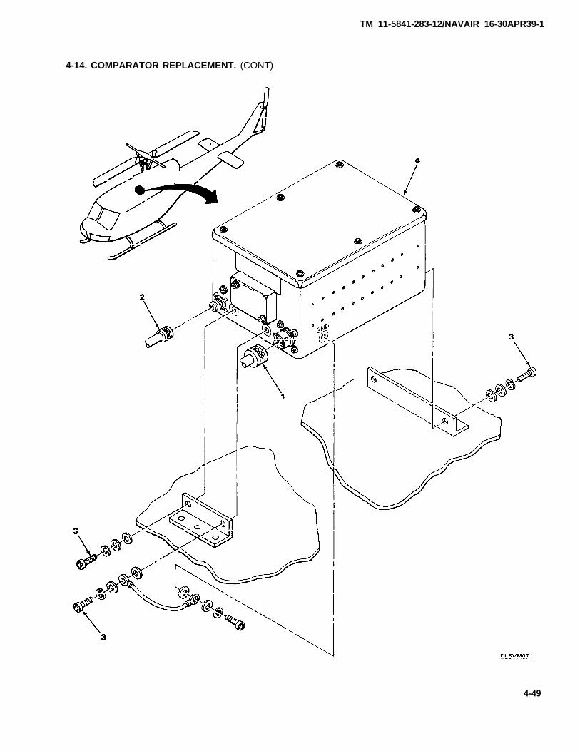
4-14. COMPARATOR REPLACEMENT.
This task covers:
1. Removal2. Installation
INITIAL SETUP
Tools Personnel Required
Tool Kit, Electronic Equipment TK-101/G One technician
Materials/Parts Equipment Condition
Comparator 28 vdc circuit breaker set OFF.NSN 5841-01-024-7739 See aircraft manual.
ACTIONLOCATION ITEM REMARKS
REMOVAL
1. Middle of quad- Connector P1 (1) Disconnect.rants I and IV and connector
P2 (2)
2. Mounting screw (3) Using cross-tip screwdriver, remove.There are four mounting screws.Step 2 is typical for all four screws.Only three screws are shown. Retainassociated hardware.
3. Comparator (4) Remove.
NOTE
Do not remove mounting bracket from airframe. Groundingstrap does not have to be removed unless replacement isrequired.
4-48
TM 11-5841-283-12/NAVAIR 16-30APR39-1
4-14. COMPARATOR REPLACEMENT. (CONT)
4-49

TM 11-5841-283-12/NAVAIR 16-30APR39-1
4-14. COMPARATOR REPLACEMENT. (CONT)
ACTIONLOCATION ITEM REMARKS
INSTALLATION
1. Middle of quad- Comparator (1) Install between mounting brackets.rants I and IV
2. Mounting screw (2) Using cross-tip screwdriver, install.There are four mounting screws.Step 2 is typical for all four screws.Only three screws are shown.
NOTE
Be sure to attach grounding strap to the mounting bracketwhen installing screws. Install associated hardware retainedduring removal.
3. Connector P1 (3) Reconnect.and connector Handtighten.P2 (4)
NOTE
Be sure that plug connector P1 is connected to jack connectorJ1, and plug connector P2 is connected to jack connector J2.
Perform a self-test (see para 2-4) and a system function test(see para 4-10).
4-50

TM 11-5841-283-12/NAVAIR 16-30APR39-1
4-14. COMPARATOR REPLACEMENT. (CONT)
4-51
TM 11-5841-283-12/NAVAIR 16-30APR39-1
4-15. CONTROL UNIT REPLACEMENT.
This task covers:
1. Removal2. Installation
INITIAL SETUP
Tools Personnel Required
Tool Kit, Electronic Equipment TK-101/G One technician
Materials/Parts Equipment Condition
Control unit 28 vdc circuit breakerNSN 5941-01-025-0378 See aircraft manual.
set OFF.
ACTIONLOCATION ITEM REMARKS
REMOVAL
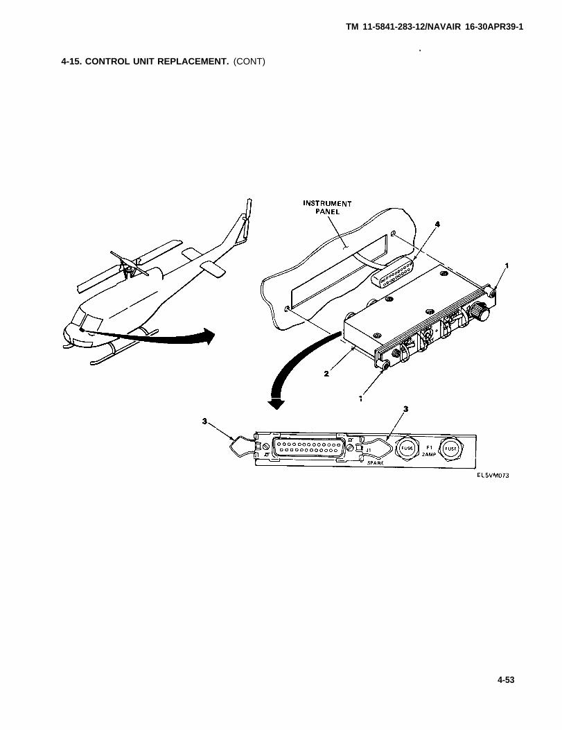
1. Instrument panel; Stud fasteners (1) Using flat-tip screwdriver, turn 90°quadrant IV counterclockwise.
2. Control unit (2) Slide out.Do not pull with force as wiringmay be pulled from connector.
Release.3. Connectorclips (3)
4.
4-52
Cableconnector (4)
Disconnect.
TM 11-5841-283-12/NAVAIR 16-30APR39-1
.4-15. CONTROL UNIT REPLACEMENT. (CONT)
4-53

4-15. CONTROL UNIT REPLACEMENT (CONT)
ACTION
LOCATION ITEM REMARKS
INSTALLATION
1. Instrument panel;quadrant IV
2.
3.
4.
Cableconnector (1)
Connectorclips (2)
Control unit (3)
Stud fasteners (4)
Reconnect.
Snap into place.
Slide into panel.
Using flat-tip screwdriver, turn 90°clockwise.
Be sure stud fasteners lock in placeand unit is secure.
NOTE
Perform a self-test (see para 2-4) and a system function(see para 4-10).
4-54/(4-55 blank)
TM 11-5841-283-12/NAVAIR 16-30APR39-1
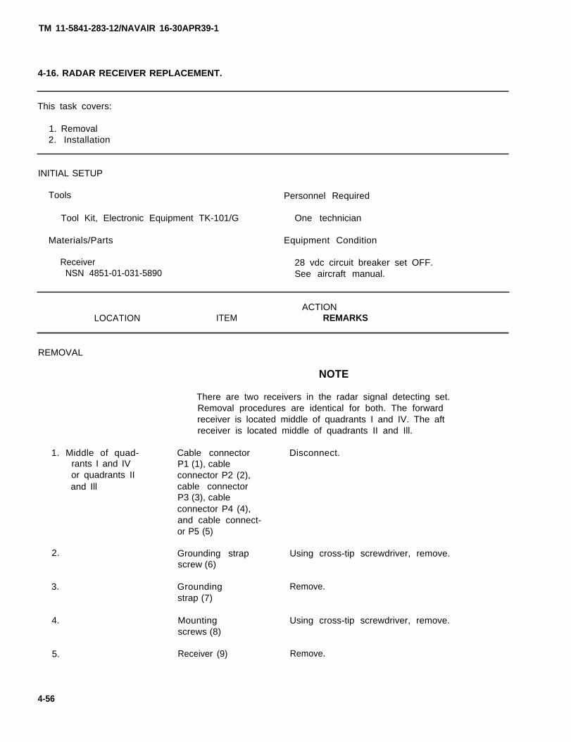
TM 11-5841-283-12/NAVAlR 16-30APR39-1
4-16. RADAR RECEIVER REPLACEMENT.
This task covers:
1. Removal2. Installation
INITIAL SETUP
Tools Personnel Required
Tool Kit, Electronic Equipment TK-101/G One technician
Materials/Parts Equipment Condition
Receiver 28 vdc circuit breaker set OFF.NSN 4851-01-031-5890 See aircraft manual.
ACTIONLOCATION ITEM REMARKS
REMOVAL
NOTE
There are two receivers in the radar signal detecting set.Removal procedures are identical for both. The forwardreceiver is located middle of quadrants I and IV. The aftreceiver is located middle of quadrants II and Ill.
1. Middle of quad-rants I and IVor quadrants IIand Ill
2.
3.
4.
5.
Cable connector Disconnect.P1 (1), cableconnector P2 (2),cable connectorP3 (3), cableconnector P4 (4),and cable connect-or P5 (5)
Grounding strapscrew (6)
Groundingstrap (7)
Mountingscrews (8)
Receiver (9)
Using cross-tip screwdriver, remove.
Remove.
Using cross-tip screwdriver, remove.
Remove.
4-56
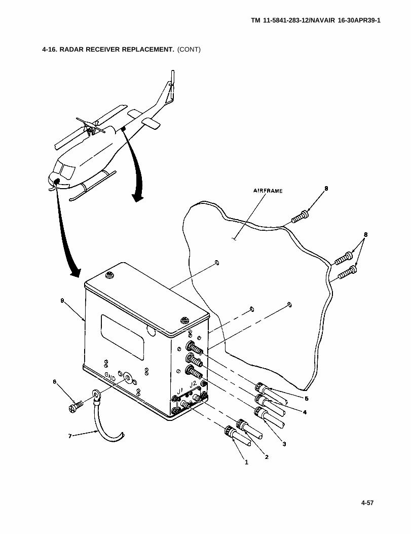
TM 11-5841-283-12/NAVAIR 16-30APR39-1
4-16. RADAR RECEIVER REPLACEMENT. (CONT)
1
4-57
4-16. RADAR RECEIVER REPLACEMENT. (CONT)
ACTIONLOCATION ITEM REMARKS
INSTALLATION
NOTE
There are two receivers in the radar signal detecting set.Installation procedures are identical for both. The forwardreceiver is located middle of quadrants I and IV. The aftreceiver is located middle of quadrants II and Ill.
1. Middle of quad- Receiver (1) Using cross-tip screwdriver, install.rants I and IV and mountingor quadrants screws (2)II and Ill
2. Groundingstrap (3) andgrounding strapscrew (4)
3.
Using cross-tip screwdriver, install.
Cable connector Reconnect.P1 (5), cableconnector P2 (6),cable connectorP3 (7), cableconnector P4 (8)and cable connect-or P5 (9)
NOTE
Be sure that plug connectors P1, P2, P3, P4, and P5 areconnected to jack connectors J1, J2, J3, J4, and J5,respectively.
Perform a self-test (see para 2-4) and a system function test(see para 4-10).
4-58
TM 11-5841-283-12/NAVAIR 16-30APR39-1
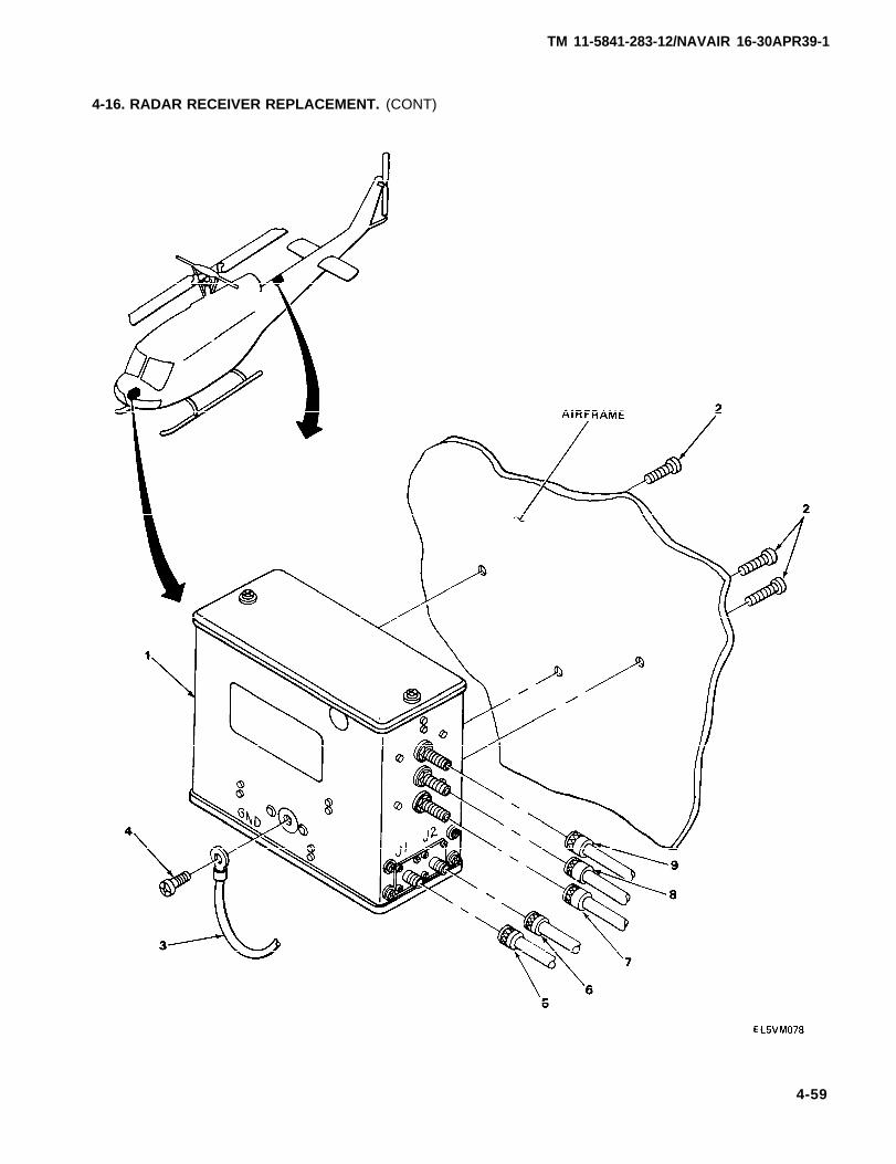
TM 11-5841-283-12/NAVAIR 16-30APR39-1
4-16. RADAR RECEIVER REPLACEMENT. (CONT)
4-59
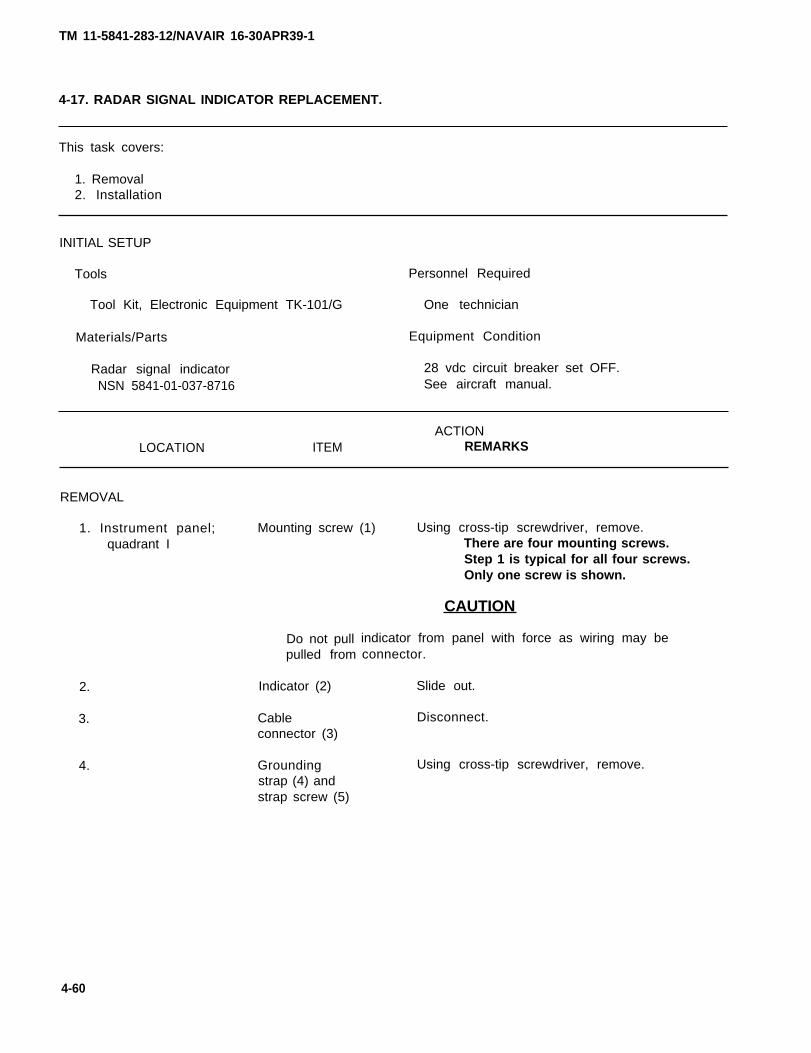
TM 11-5841-283-12/NAVAIR 16-30APR39-1
4-17. RADAR SIGNAL INDICATOR REPLACEMENT.
This task covers:
1. Removal2. Installation
INITIAL SETUP
Tools Personnel Required
Tool Kit, Electronic Equipment TK-101/G One technician
Materials/Parts Equipment Condition
Radar signal indicator 28 vdc circuit breaker set OFF.NSN 5841-01-037-8716 See aircraft manual.
ACTIONLOCATION ITEM REMARKS
REMOVAL
1. Instrument panel; Mounting screw (1) Using cross-tip screwdriver, remove.
2.
3.
4.
quadrant I
Do not pullpulled from
Indicator (2)
Cableconnector (3)
Groundingstrap (4) andstrap screw (5)
There are four mounting screws.Step 1 is typical for all four screws.Only one screw is shown.
CAUTION
indicator from panel with force as wiring may beconnector.
Slide out.
Disconnect.
Using cross-tip screwdriver, remove.
4-60
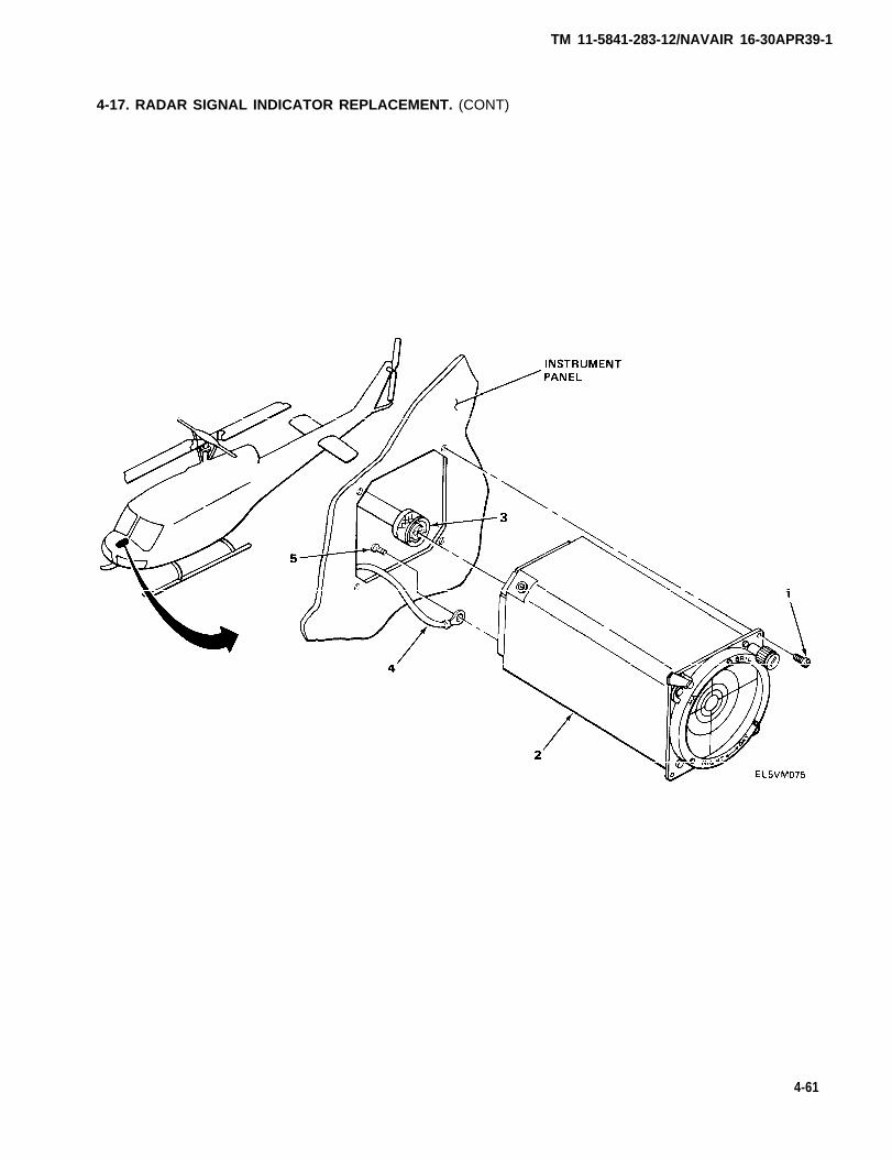
TM 11-5841-283-12/NAVAIR 16-30APR39-1
4-17. RADAR SIGNAL INDICATOR REPLACEMENT. (CONT)
4-61

TM 11-5841-283-12/NAVAIR 16-30APR39-1
4-17. RADAR SIGNAL INDICATOR REPLACEMENT. (CONT)
ACTION
LOCATION ITEM REMARKS
INSTALLATION
1. Instrument panel; Grounding strapquadrant I (1) and strap
screw (2)
Using cross-tip screwdriver, install.
2. Cableconnector (3)
3. Indicator (4)
4. Mountingscrews (5)
Reconnect.Handtighten.
Slide into panel.
Using cross-tip screwdriver, install.There are four mounting screws. Step4 is typical for all four screws. Onlyone screw is shown.
NOTE
Perform a self-test (see para 2-4) and a system function test(see para 4-10).
4-62/(4-63 blank)
TM 11-5841-283-12/NAVAIR 16-30APR39-1
4-18. SPIRAL ANTENNA REPLACEMENT.
This task covers:
1. Removal2. Installation
INITIAL SETUP
Tools
Tool Kit, Electronic Equipment TK-101/G
Materials/Parts
Left Spiral AntennaNSN 5895-01-035-5970
Right Spiral AntennaNSN 5985-01-026-3926
Personnel Required
One technician
Equipment Condition
28 vdc circuit breaker set OFF.See aircraft manual.
ACTIONLOCATION ITEM REMARKS
REMOVAL
There are four spiral antennas: two left spiral and tworight spiral. The term spiral refers to the windingdirection of the antenna, not left or right side of aircraft.
Always replace antenna with same type removed (left or rightspiral).
One antenna is located in each of the four quadrants of theaircraft (I, II, Ill, and IV).
CAUTION
All antennas must be mounted in the same way. The radar setwill not work properly if they are not. Each antenna has awhite dot on the rear face. The white dot must be in thesame position for all antennas (up, down, left, or right).
4-64
NOTE
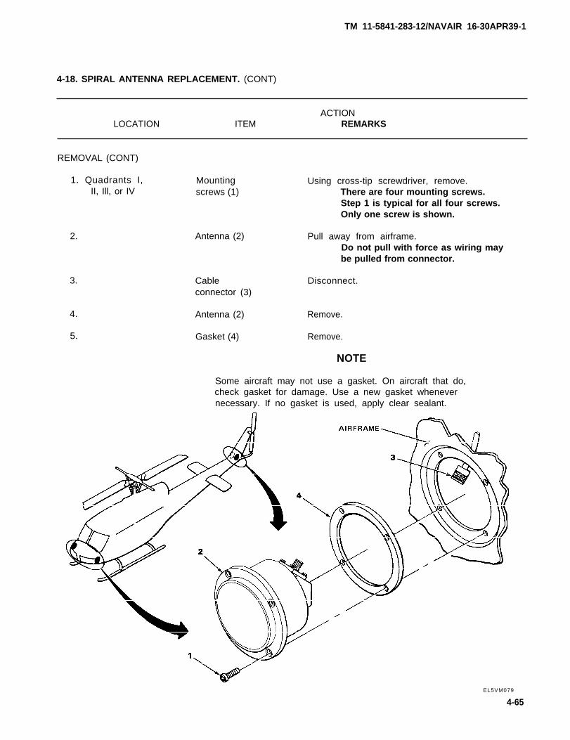
TM 11-5841-283-12/NAVAIR 16-30APR39-1
4-18. SPIRAL ANTENNA REPLACEMENT. (CONT)
ACTIONLOCATION ITEM REMARKS
REMOVAL (CONT)
1. Quadrants I,II, Ill, or IV
2.
3.
4.
5.
Mountingscrews (1)
Antenna (2)
Cableconnector (3)
Antenna (2)
Gasket (4)
Using cross-tip screwdriver, remove.There are four mounting screws.Step 1 is typical for all four screws.Only one screw is shown.
Pull away from airframe.Do not pull with force as wiring maybe pulled from connector.
Disconnect.
Remove.
Remove.
NOTE
Some aircraft may not use a gasket. On aircraft that do,check gasket for damage. Use a new gasket whenevernecessary. If no gasket is used, apply clear sealant.
EL5VM079
4-65
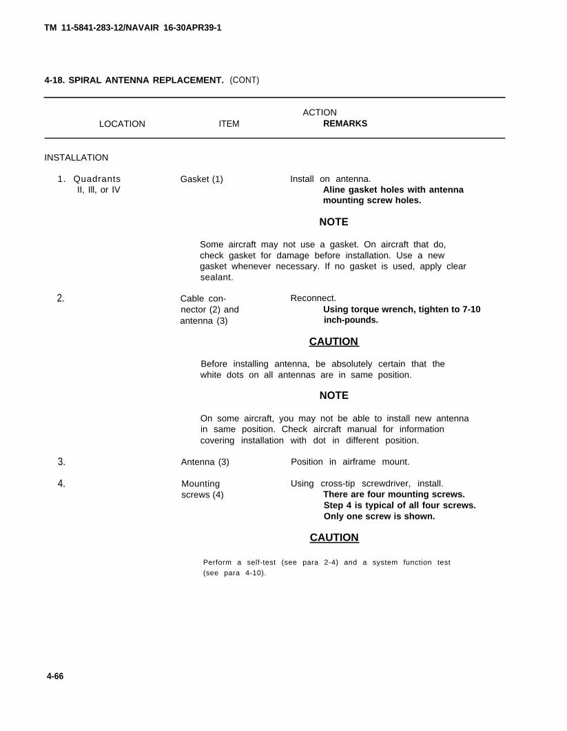
TM 11-5841-283-12/NAVAIR 16-30APR39-1
4-18. SPIRAL ANTENNA REPLACEMENT. (CONT)
ACTIONLOCATION ITEM REMARKS
INSTALLATION
1. QuadrantsII, Ill, or IV
2.
3.
4.
Gasket (1) Install on antenna.Aline gasket holes with antennamounting screw holes.
NOTE
Some aircraft may not use a gasket. On aircraft that do,check gasket for damage before installation. Use a newgasket whenever necessary. If no gasket is used, apply clearsealant.
Cable con- Reconnect.nector (2) and Using torque wrench, tighten to 7-10antenna (3) inch-pounds.
CAUTION
Before installing antenna, be absolutely certain that thewhite dots on all antennas are in same position.
NOTE
On some aircraft, you may not be able to install new antennain same position. Check aircraft manual for informationcovering installation with dot in different position.
Antenna (3) Position in airframe mount.
Mounting Using cross-tip screwdriver, install.screws (4) There are four mounting screws.
Step 4 is typical of all four screws.Only one screw is shown.
CAUTION
Perform a self-test (see para 2-4) and a system function test
(see para 4-10).
4-66
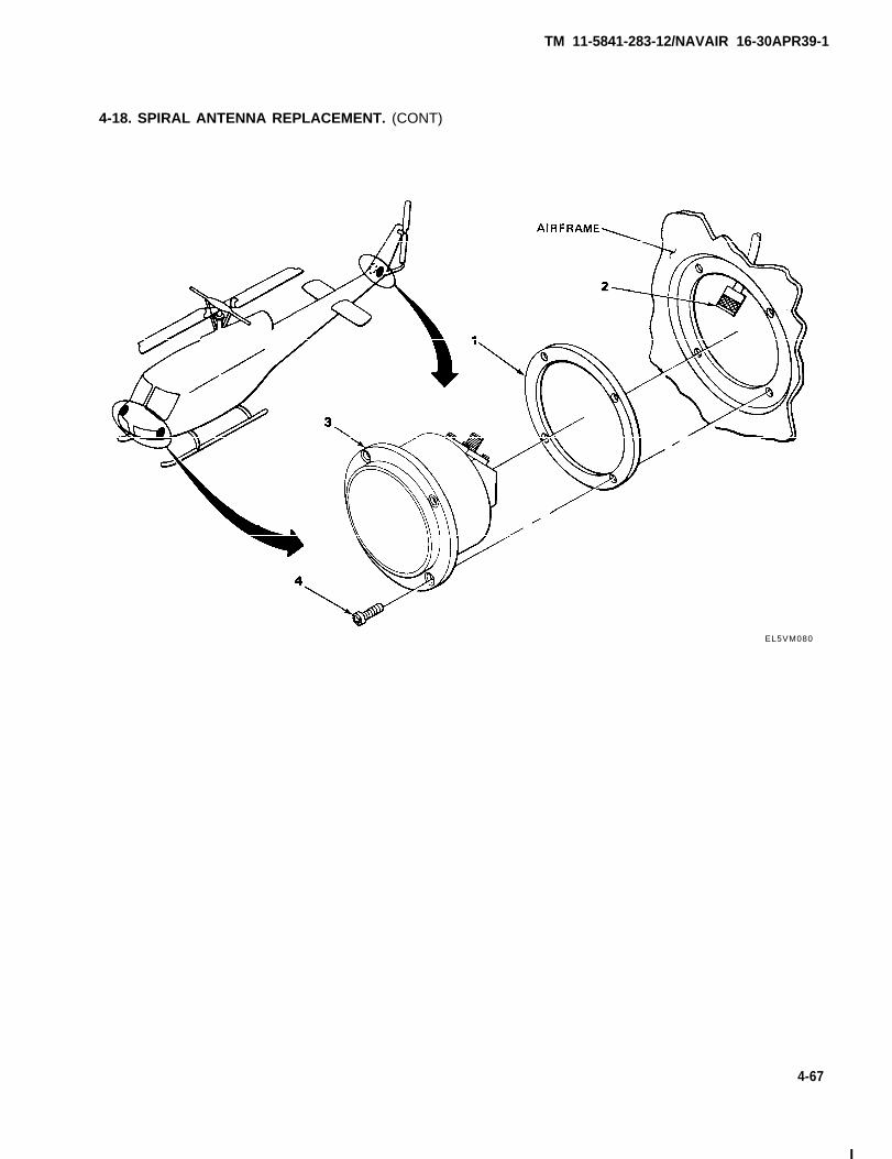
TM 11-5841-283-12/NAVAIR 16-30APR39-1
4-18. SPIRAL ANTENNA REPLACEMENT. (CONT)
EL5VM080
4-67
I
TM 11-5841-283-121NAVAlR 16-30APR39-1
4-19. REPLACEMENT OF AUDIO CONTROL KNOB.
This task covers:
1. Removal2. Installation
INITIAL SETUP
Tools Personnel Required
Tool Kit, Electronic Equipment TK-101/G One operator
Materials/Parts Equipment Condition
Control Knob 28 vdc circuit breaker set OFF.NSN 5355-00-762-1489 See aircraft manual.
ACTIONLOCATION ITEM REMARKS
REMOVAL
1. Control unit
2.
Setscrews (1)
Control knob (2)
Using Allen wrench, loosen.
Remove.Throw away.
INSTALLATION
1. Control unit Control knob (2) Install.Aline pointer 180° from flat sideof shaft.
2. Setscrews (1) Using Allen wrench, tighten.
4-68

TM 11-5841-283-12/NAVAIR 16-30APR39-1
4-19. REPLACEMENT OF AUDIO CONTROL KNOB. (CONT)
EL5VM027
4-69
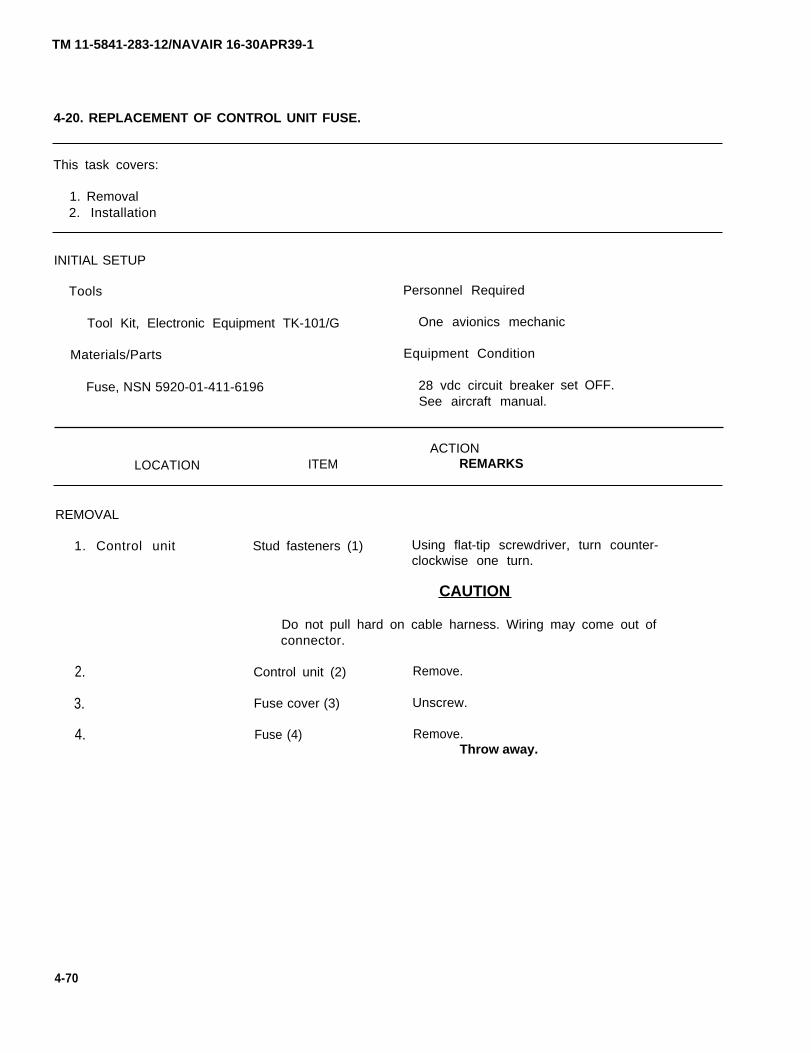
4-20. REPLACEMENT OF CONTROL UNIT FUSE.
This task covers:
1. Removal2. Installation
INITIAL SETUP
Tools Personnel Required
Tool Kit, Electronic Equipment TK-101/G One avionics mechanic
Materials/Parts Equipment Condition
Fuse, NSN 5920-01-411-6196 28 vdc circuit breakerSee aircraft manual.
set OFF.
ACTIONLOCATION ITEM REMARKS
REMOVAL
1. Control unit
2.
3.
4.
Stud fasteners (1) Using flat-tip screwdriver, turn counter-clockwise one turn.
CAUTION
Do not pull hard on cable harness. Wiring may come out ofconnector.
Control unit (2) Remove.
Fuse cover (3) Unscrew.
Fuse (4) Remove.Throw away.
4-70
TM 11-5841-283-12/NAVAIR 16-30APR39-1
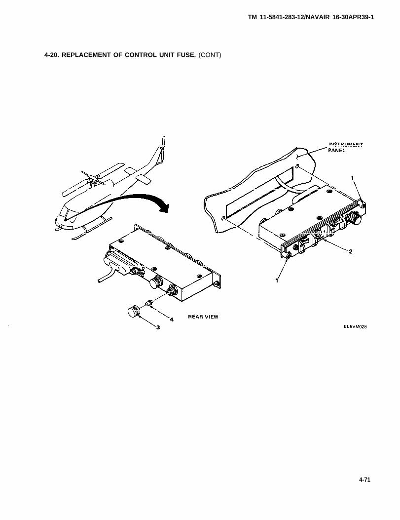
TM 11-5841-283-12/NAVAIR 16-30APR39-1
4-20. REPLACEMENT OF CONTROL UNIT FUSE. (CONT)
4-71

TM 11-5841-283-12/NAVAIR 16-30APR39-1
4-20. REPLACEMENT OF CONTROL UNIT FUSE. (CONT)
ACTIONLOCATION ITEM REMARKS
INSTALLATION
1. Control unit
2.
3.
4.
Fuse (1) Install.Use spare fuse stored in back ofcontrol unit.
NOTE
Replace spare fuse as soon as possible.
Fuse cover (2)
Control unit (3)
Stud fasteners (4)
Screw in place.
Install.
Using flat-tip screwdriver, turn clockwiseone-quarter turn to lock.
4-72/(4-73 blank)
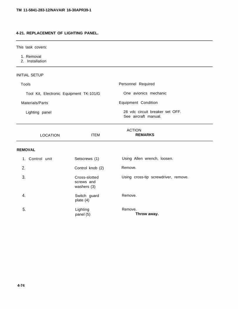
TM 11-5841-283-12/NAVAIR 16-30APR39-1
4-21. REPLACEMENT OF LIGHTING PANEL.
This task covers:
1. Removal2. Installation
INITIAL SETUP
Tools Personnel Required
Tool Kit, Electronic Equipment TK-101/G One avionics mechanic
Materials/Parts Equipment Condition
Lighting paneI 28 vdc circuit breakerSee aircraft manual.
set OFF.
ACTIONLOCATION ITEM REMARKS
REMOVAL
1. Control unit
2.
3.
4.
5.
Setscrews (1)
Control knob (2)
Cross-slottedscrews andwashers (3)
Switch guardplate (4)
Lightingpanel (5)
Using Allen wrench, loosen.
Remove.
Using cross-tip screwdriver, remove.
Remove.
Remove.Throw away.
4-74
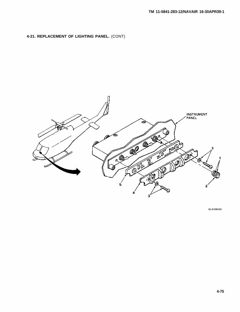
TM 11-5841-283-12/NAVAIR 16-30APR39-1
4-21. REPLACEMENT OF LIGHTING PANEL. (CONT)
EL5VM030
4-75
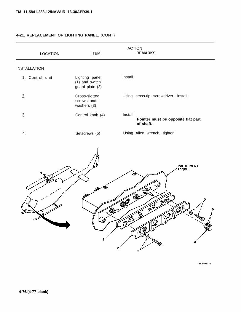
TM 11-5841-283-12/NAVAIR 16-30APR39-1
4-21. REPLACEMENT OF LIGHTING PANEL. (CONT)
ACTIONLOCATION ITEM REMARKS
INSTALLATION
1. Control unit
2.
3.
4.
Lighting panel(1) and switchguard plate (2)
Cross-slottedscrews andwashers (3)
Control knob (4)
Setscrews (5)
Install.
Using cross-tip screwdriver, install.
Install.Pointer must be opposite flat partof shaft.
Using Allen wrench, tighten.
EL5VM031
4-76/(4-77 blank)
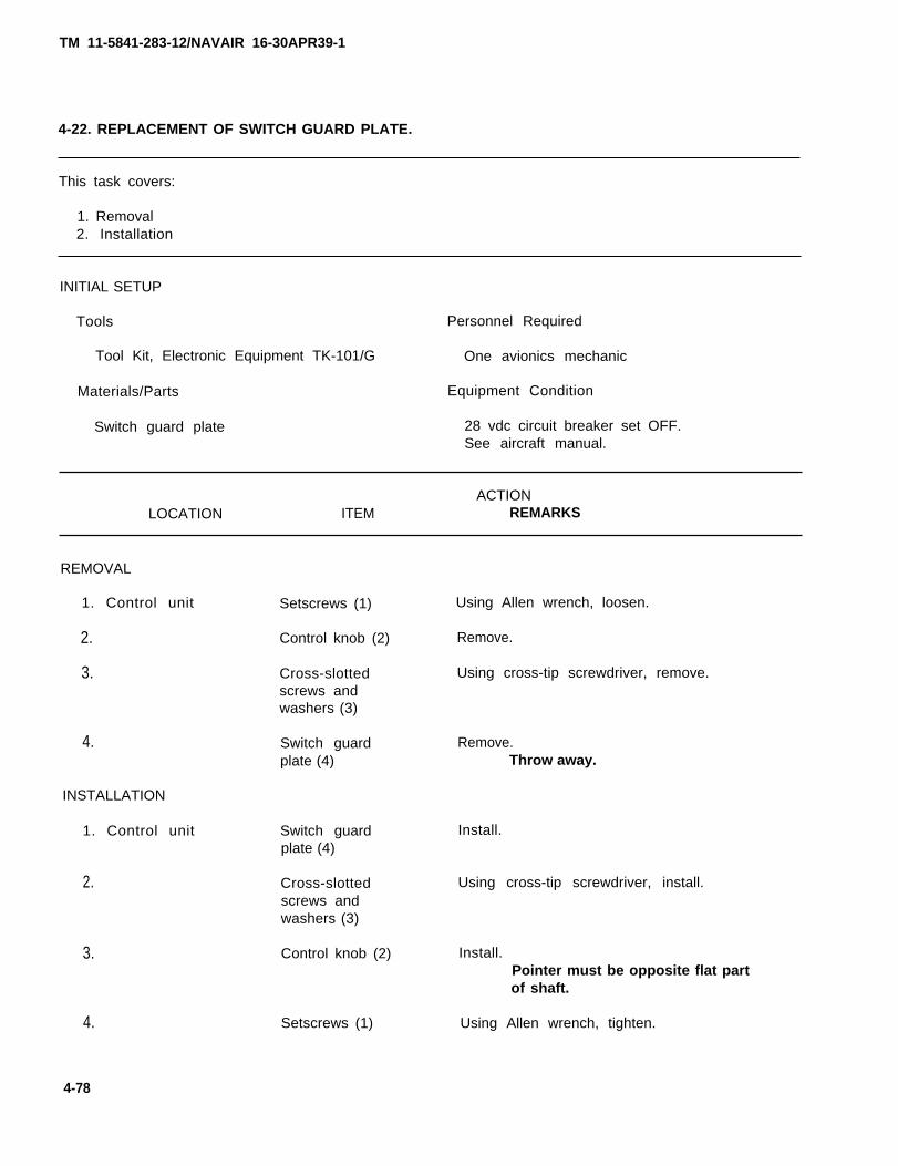
TM 11-5841-283-12/NAVAIR 16-30APR39-1
4-22. REPLACEMENT OF SWITCH GUARD PLATE.
This task covers:
1. Removal2. Installation
INITIAL SETUP
Tools Personnel Required
Tool Kit, Electronic Equipment TK-101/G One avionics mechanic
Materials/Parts Equipment Condition
Switch guard plate 28 vdc circuit breaker set OFF.See aircraft manual.
ACTIONLOCATION ITEM REMARKS
REMOVAL
1. Control unit Setscrews (1) Using Allen wrench, loosen.
Remove.
Using cross-tip screwdriver, remove.
2. Control knob (2)
3. Cross-slottedscrews andwashers (3)
4.
INSTALLATION
1. Control unit
2.
Switch guardplate (4)
Remove.Throw away.
Switch guardplate (4)
Install.
Cross-slottedscrews andwashers (3)
Using cross-tip screwdriver, install.
3. Install.Pointer must be opposite flat partof shaft.
Using Allen wrench, tighten.
Control knob (2)
4. Setscrews (1)
4-78
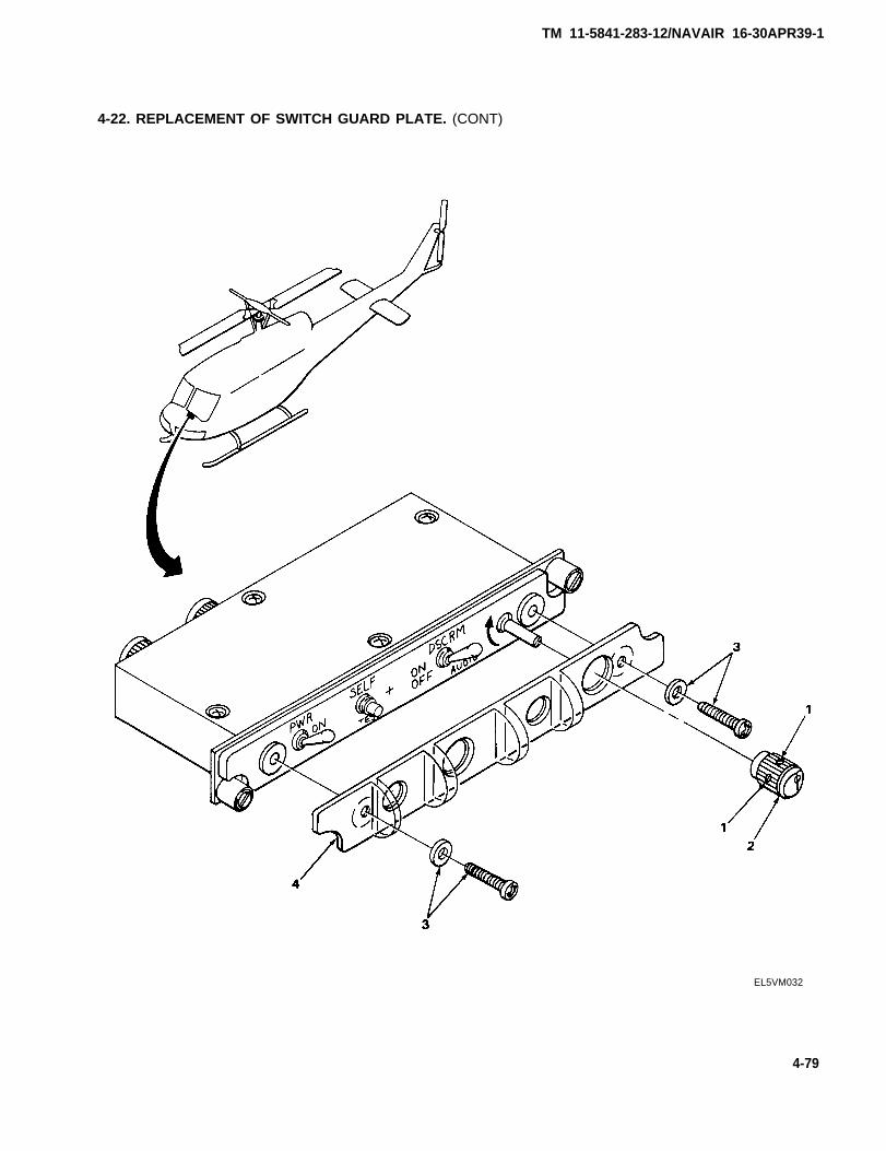
TM 11-5841-283-12/NAVAIR 16-30APR39-1
4-22. REPLACEMENT OF SWITCH GUARD PLATE. (CONT)
EL5VM032
4-79
TM 11-5841-283-12/NAVAIR 16-30APR39-1
4-23. PAINTING.
Procedure for repainting or touching up the painted surfaces of the units and supplies availablewill be those given in TB 43-0118 and SB 11-573.
4-24. PAINTING BLADE ANTENNA.
This task covers:
Painting the blade antenna
INITIAL SETUP
Tools
None
Materials/Parts
Primer, color Y, composition L,per 11-P-1757
Enamel, semi-gloss, black, type N,color number 27038, per FED-STD-595
Personnel Required
One technician
Equipment Condition
28 vdc circuit breaker set OFF.See aircraft manual.
ACTIONLOCATION ITEM REMARKS
1. Middle of quad-rants I and IV
2.
3.
4.
Blade antenna (1)
CAUTION
Do not use any paint containing lead.
Remove.See paragraph 4-13.
Clean.See paragraph 4-11.
Paint exposed metal parts with primer.
Paint antenna surfaces with enamel.
4-80
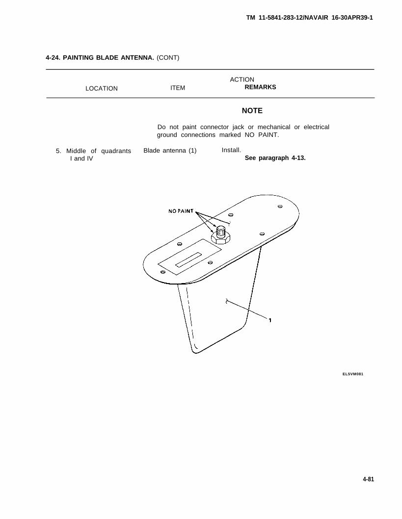
TM 11-5841-283-12/NAVAIR 16-30APR39-1
4-24. PAINTING BLADE ANTENNA. (CONT)
ACTIONLOCATION ITEM REMARKS
NOTE
Do not paint connector jack or mechanical or electricalground connections marked NO PAINT.
5. Middle of quadrants Blade antenna (1) Install.I and IV See paragraph 4-13.
EL5VM081
4-81
TM 11-5841-283-12/NAVAlR 16-30 APR39-1
4-25. PAINTING COMPARATOR.
This task covers:
Painting the comparator
INITIAL SETUP
Tools Personnel Required
None One technician
Materials/Parts Equipment Condition
Primer, color Y, composition L, 28 vdc circuit breaker set OFF.per TT-P-1757 See aircraft manual.
Lusterless grey enamel per TT-E-527,color number 36231 per FED-STD-595
ACTIONLOCATION ITEM REMARKS
1. Middle of quad- Comparator (1) Remove.rants I and IV See paragraph 4-14.
2. Clean.See paragraph 4-11.
3. Paint exposed metal parts with primer.
CAUTION
4.
5.
Do not apply paint to areas marked NO PAINT.
Paint comparator surfaces with enamel.
NOTE
Do not paint the inside or top edge of case. Do not painttop cover plate on the inside.
Install.See paragraph 4-14.
4-82
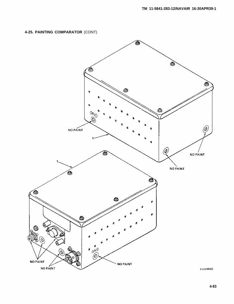
TM 11-5841-283-12/NAVAIR 16-30APR39-1
4-83
4-25. PAINTING COMPARATOR (CONT)
TM 11-5841-283-12/NAVAIR 16-30APR39-1
4-25. PAINTING CONTROL UNIT.
This task covers:
Painting the control unit
INITIAL SETUP
Tools
None
Materials/Parts
Personnel Required
One technician
Equipment Condition
Primer, color Y, composition L, per 28 vdc circuit breaker set OFF.TT-P-1757 See aircraft manual.
Lusterless black enamel per TT-E-527,color number 37938 per FED-STD-595
ACTIONLOCATION ITEM REMARKS
PAINTING
1. Instrument panel; Control unit (1)quadrant IV
2.
3.
4.
Remove.See paragraph 4-15.
Clean.See paragraph 4-11.
Paint exposed metal parts with primer.
Paint control unit surfaces with enamel.
NOTE
Do not paint the lighting panel. Do not paint areas markedNO PAINT.
5. Install.See paragraph 4-15.
4-84
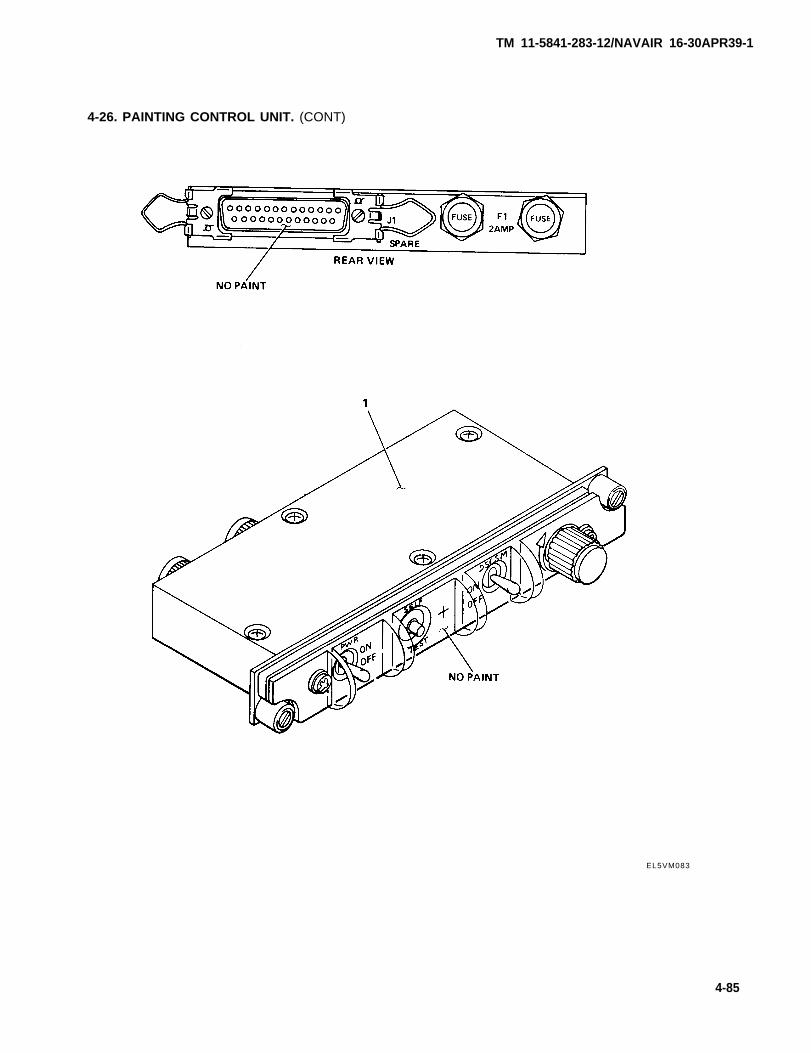
TM 11-5841-283-12/NAVAIR 16-30APR39-1
4-26. PAINTING CONTROL UNIT. (CONT)
EL5VM083
4-85
TM 11-5841-283-12/NAVAIR 16-30APR39-1
4-27. PAINTING RADAR RECEIVERS.
This task covers:
Painting the radar receivers
INITIAL SETUP
Tools
None
Materials/Parts
Primer, color Y,per TT-P-1757
Lusterless grey
Personnel Required
One technician
Equipment Condition
composition L, 28 vdc circuit breaker set OFF.See aircraft manual.
enamel per TT-E-527,color number 36231 per FED-STD-595
ACTIONREMARKSLOCATION ITEM
NOTE
There are two radar receivers. One is located middle ofquadrant I and IV, the other is located middle of quadrant IIand Ill.
1. Middle of quad- Radar receiver (1) Remove.
rants I and IV See paragraph 4-16.
or II and Ill
2.
3.
Clean.See paragraph 4-11.
Paint exposed metal parts with primer.
CAUTION
Do not apply paint to areas marked NO PAINT.
4-86
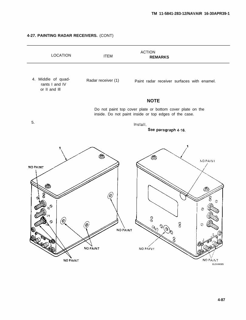
TM 11-5841-283-12/NAVAIR 16-30APR39-1
4-27. PAINTING RADAR RECEIVERS. (CONT)
LOCATION ITEMACTION
REMARKS
4. Middle of quad-rants I and IVor II and Ill
5.
Radar receiver (1) Paint radar receiver surfaces with enamel.
NOTE
Do not paint top cover plate or bottom cover plate on theinside. Do not paint inside or top edges of the case.
EL5VM085
4-87
TM 11-5841-283-12/NAVAIR 16-30APR39-1
4-28. PAINTING RADAR SIGNAL INDICATOR.
This task covers:
Painting the radar signal indicator
INITIAL SETUP
Tools
None
Materials/Parts
Primer, color Y, composition L, perTT-P-1757
Lusterless black enamel per TT-E-527,color number 37938 per FED-STD-595
Personnel Required
One technician
Equipment Condition
28 vdc circuit breaker set OFF.See aircraft manual.
ACTIONLOCATION ITEM REMARKS
1. Instrument panel; Indicator (1)quadrant I
2.
3.
4.
5.
Remove.See paragraph 4-17.
Clean.See paragraph 4-11.
Paint exposed metal parts with primer.
CAUTION
Do not apply paint to areas marked NO PAINT.
Paint indicator surfaces with enamel.
NOTE
Do not paint indicator front panel.
Install.See paragraph 4-17.
4-88
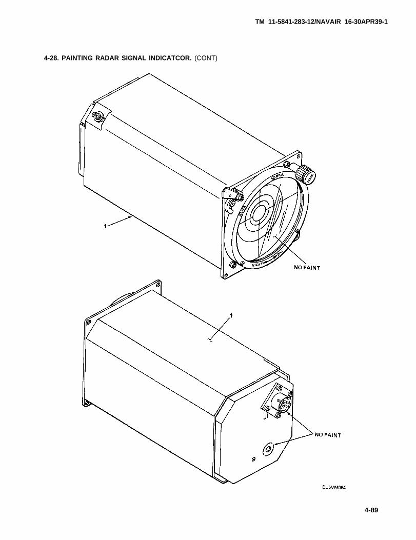
TM 11-5841-283-12/NAVAIR 16-30APR39-1
4-28. PAINTING RADAR SIGNAL INDICATCOR. (CONT)
4-89
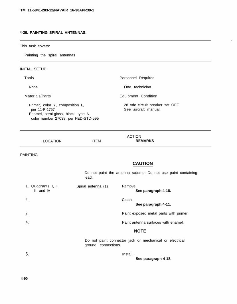
TM 11-5841-283-12/NAVAIR 16-30APR39-1
4-29. PAINTING SPIRAL ANTENNAS.
,
This task covers:
Painting the spiral antennas
INITIAL SETUP
Tools Personnel Required
None One technician
Materials/Parts Equipment Condition
Primer, color Y, composition L, 28 vdc circuit breaker set OFF.per 11-P-1757 See aircraft manual.
Enamel, semi-gloss, black, type N,color number 27038, per FED-STD-595
ACTIONLOCATION ITEM REMARKS
PAINTING
1. Quadrants I, IIIll, and IV
2.
3.
4.
5.
CAUTION
Do not paint the antenna radome. Do not use paint containinglead.
Spiral antenna (1) Remove.See paragraph 4-18.
Clean.See paragraph 4-11.
Paint exposed metal parts with primer.
Paint antenna surfaces with enamel.
NOTE
Do not paint connector jack or mechanical or electricalground connections.
Install.See paragraph 4-18.
4-90
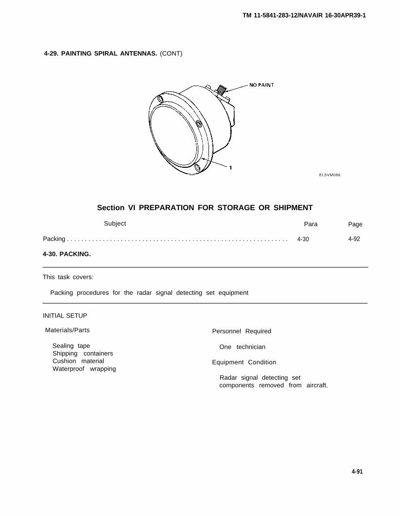
TM 11-5841-283-12/NAVAIR 16-30APR39-1
4-29. PAINTING SPIRAL ANTENNAS. (CONT)
EL5VM086
Section VI PREPARATION FOR STORAGE OR SHIPMENT
Subject Para Page
Packing . . . . . . . . . . . . . . . . . . . . . . . . . . . . . . . . . . . . . . . . . . . . . . . . . . . . . . . . . . . . . . 4-30 4-92
4-30. PACKING.
This task covers:
Packing procedures for the radar signal detecting set equipment
INITIAL SETUP
Materials/Parts
Sealing tapeShipping containersCushion materialWaterproof wrapping
Personnel Required
One technician
Equipment Condition
Radar signal detecting setcomponents removed from aircraft.
4-91
TM 11-5841-283-12/NAVAIR 16-30APR39-1
4-30. PACKING. (CONT)
ACTION
LOCATION ITEM REMARKS
1.
2.
3.
4.
5.
6.
Cushionand component (2)
Waterproofwrapping (3)
Unit container (4),flaps (5) andsealing tape (6)
Corrugated ship-ping container (7)
Cushionmaterial (8)
Cover flaps (9) andsealing tape (10)
Wrap cushion material around component.Do this for all 10 components.
Put around component and seal.Do this for all 10 components.
Place wrapped component inside andseal flaps.
Place unit containers inside.
Insert between unit containers and inside wallsof shipping container.
Pack cushion material tightly.
Close and seal.
4-92
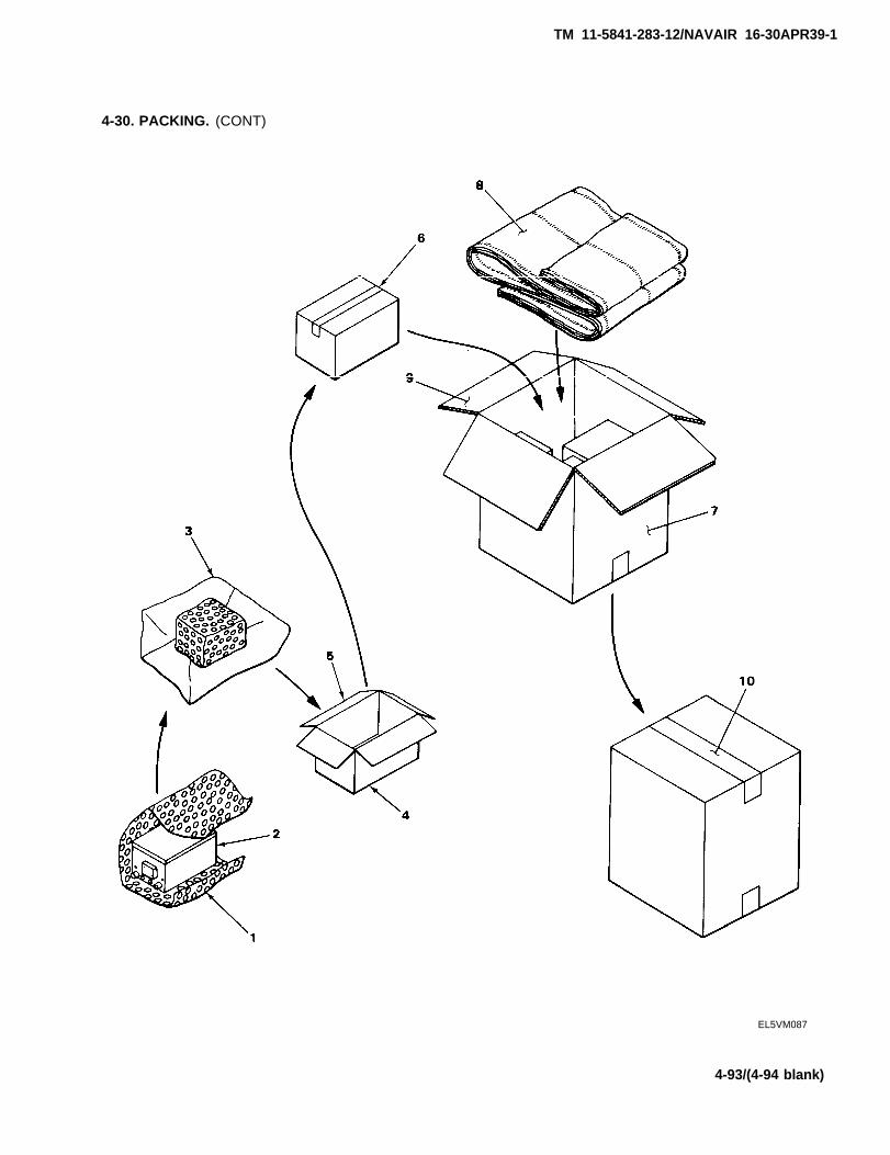
TM 11-5841-283-12/NAVAIR 16-30APR39-1
4-30. PACKING. (CONT)
EL5VM087
4-93/(4-94 blank)
APPENDIX A
REFERENCES
A-1. SCOPE.
The following is a list of all forms, technical bulletins, and technical manuals referenced inthis manual.
A-2. PAMPHLETS.
Consolidated Index of Army Publications and Blank Forms . . . . . . . . . . . . . . . DA PAM 310-1
A-3. FORMS.
Discrepancy in Shipment Report (DISREP) . . . . . . . . . . . . . . . . . . . . . . . . . . . . . SF-361Report of Discrepancy (ROD) . . . . . . . . . . . . . . . . . . . . . . . . . . . . . . . . . . . . . . . . SF-364Quality Deficiency Report . . . . . . . . . . . . . . . . . . . . . . . . . . . . . . . . . . . . . . . . . . . SF-368Recommended Changes to Publications and Blank Forms. . . . . . . . . . . . . . . . DA FORM 2028Recommended Changes to Equipment Technical Manuals . . . . . . . . . . . . . . . DA FORM 2028-2Equipment Inspection and Maintenance Worksheet . . . . . . . . . . . . . . . . . . . . . DA FORM 2404
A-4. SUPPLY BULLETINS.
Painting and Preservation Supplies Available for FieldUse for Electronics Command Equipment . . . . . . . . . . . . . . . . . . . . . . . . . . . . S611-573
Preservation, Packaging, Packing and Marking Materials,Supplies, and Equipment Used by Army . . . . . . . . . . . . . . . . . . . . . . . . . . . . . . SB38-100
A-5. TECHNICAL BULLETINS.
Field Instructions for Painting and Preserving ElectronicsCommand Equipment Including Camouflage Pattern Painting ofElectrical Equipment Shelters . . . . . . . . . . . . . . . . . . . . . . . . . . . . . . . . . . . . . . TB 43-0118
A-6. TECHNICAL MANUALS.
Organizational, Direct Support, and General Support Maintenance,Repair Parts and Special Tools List for Radar Signal DetectingSet AN/APR-39(V)1 . . . . . . . . . . . . . . . . . . . . . . . . . . . . . . . . . . . . . . . . . . . . . . . . TM 11-5841-283-24P
Operator and Organizational Maintenance Manual: Simulator, RadarSignal SM-674/UPM (NSN 6940-01-031-5887) and Test Adapter,Radar Signal MX-9843/APR-39(V) (NSN 5841-01-025-0379) . . . . . . . . . . . . . . . . TM 11-8940-211-12
The Army Maintenance Management System (TAMMS) . . . . . . . . . . . . . . . . . . TM 38-750Administrative Storage of Equipment . . . . . . . . . . . . . . . . . . . . . . . . . . . . . . . . . TM 740-90-1Procedures for Destruction of Electronic Material to Prevent
Enemy Use (Electronics Command) . . . . . . . . . . . . . . . . . . . . . . . . . . . . . . . . . . TM 750-244-2
A-1/(A-2 blank)
TM-11-5841-283-12/NAVAIR 16-30APR39-1

APPENDIX B
MAINTENANCE ALLOCATION
Section I INTRODUCTION
B-1. GENERAL.
This appendix provides a summary of maintenance operations for the radar signal detecting set.It authorizes categories of maintenance for specific maintenance functions on repairable itemsand components and the tools and equipment required to perform each function. This appendix maybe used as an aid in planning maintenance operations.
B-2. MAINTENANCE FUNCTIONS.
Maintenance functions will be limited to and defined as follows:
a. Inspect. To determine the serviceability of an item by comparing its physical, mechanical,and/or electrical characteristics with established standards through examination.
b. Test. To verify serviceability and to detect incipient failure by measuring themechanical, or electrical characteristics of an item and comparing those characteristics withprescribed standards.
c. Service. Operations required periodically to keep an item in proper operating condition,i.e., to clean (decontaminate), to preserve, to drain, to paint, or to replenish fuel,lubricants, chemical fluids, or compressed air supplies.
d. Adjust. To maintain, within prescribed limits, by bringing into proper or exact position,or by setting the operating characteristics to specified parameters.
e. Aline. To adjust specified variable elements of an item to bring about optimum or desiredperformance.
f. Calibrate. To determine and cause corrections to be made or to be adjusted on instrumentsor test measuring and diagnostic equipment used in precision measurement. Consists ofcomparisons of two instruments, one of which is a certified standard of known accuracy, to detectand adjust any discrepancy in the accuracy of the instrument being compared.
g. Install. The act of emplacing, seating, or fixing into position an item, part, or module(component or assembly) in a manner to allow the proper functioning of the equipment or system.
h. Replace. The act of substituting a serviceable like type part, subassembly, or module(component or assembly) for an unserviceable counterpart.
i. Repair. The application of maintenance services (inspect, test, service, adjust, aline,calibrate, replace) or other maintenance actions (welding, grinding, riveting, straightening,facing, remachining, or resurfacing) to restore serviceability to an item by correcting specificdamage, fault, malfunction, or failure in a part, subassembly, module (component or assembly),end item, or system.
B-1
TM 11-5841-283-12/NAVAIR 16-30APR39-1
B-2. MAINTENANCE FUNCTIONS. (CONT)
j. Overhaul. That maintenance effort (service/action) necessary to restore an item to acompletely serviceable/operational condition as prescribed by maintenance standards (i.e., DMWR)in appropriate technical publications. Overhaul is normally the highest degree of maintenanceperformed by the Army. Overhaul does not normally return an item to like new condition.
k. Rebuild. Consists of those services necessary for the restoration of unserviceableequipment to a like new condition, in accordance with original manufacturing standards. Rebuildis the highest degree of materiel maintenance applied to Army equipment. The rebuild operationincludes the act of returning to zero those age measurements (hours, miles, etc) considered inclassifying Army equipment components.
B-3. COLUMN ENTRIES.
a. Column 1, Group Number. Column 1 lists group numbers, the purpose of which is to identifycomponents, assemblies, subassemblies, and modules with the next higher assembly.
b. Column 2, Component/Assembly. Column 2 contains the noun names of components,assemblies, subassemblies, and modules for which maintenance is authorized.
c. Column 3, Maintenance Function. Column 3 lists the functions to be performed on the itemlisted in column 2. When items are listed without maintenance functions, it is solely forpurpose of having the group numbers in the MAC and RPSTL coincide.
d. Column 4, Maintenance Category. Column 4 specifies, by the listing of a “work time” figurein the appropriate subcolumn(s), the lowest level of maintenance authorized to perform thefunction listed in column 3. This figure represents the active time required to perform thatmaintenance function at the indicated category of maintenance. If the number or complexity ofthe tasks within the listed maintenance function varies at different maintenance categories,appropriate “work time” figures will be shown for each category. The number of task-hoursspecified by the “work time” figure represents the average time required to restore an item(assembly, subassembly, component, module, end item or system) to a serviceable condition undertypical field operating conditions. This time includes preparation time, troubleshooting time,and quality assurance/quality control time in addition to the time required to perform thespecific tasks identified for the maintenance functions authorized in the maintenance allocationchart. Subcolumns of column 4 are as follows:
C - Operator/Crew AVIM - Aviation Intermediate MaintenanceO - Organizational AVUM - Aviation Unit MaintenanceF - Direct SupportH - General SupportL - Special Repair Activity (SRA)D - Depot
e. Column 5, Tools and Equipment. Column 5 specifies by code those common tool sets (notindividual tools) and special tools, test and support equipment required to perform thedesignated function.
f. Column 6, Remarks. Column 6 contains an alphabetic code which leads to the remark insection IV, Remarks, which is pertinent to the item opposite the particular code.
B-2
TM 11-5841-283-12/NAVAIR 16-30APR39-1
TM 11-5841-283-12/NAVAIR 16-30APR39-1
B-4. TOOL AND TEST EQUIPMENT REQUIREMENTS.
a. Tool or Test Equipment Reference Code. The numbers in this column coincide with thenumbers used in the tools and equipment column of the MAC. The numbers indicate the applicabletool or test equipment for the maintenance functions,
b. Maintenance Category. The codes in this column indicate the maintenance category allocatedto the tool or test equipment.
c. Nomenclature. This column lists the noun name and nomenclature of the tools and testequipment required to perform the maintenance functions.
d. National/NATO Stock Number. This column lists the national/NATO stock number of thespecific tool or test equipment.
e. Tool Number. This column lists the manufacturer’s part number of the tool followed by thefederal supply code for manufacturers (5-digit) in parentheses.
B-5. REMARKS.
a. Reference Code. This code refers to the appropriate item in section II, column 6.
b. Remarks. This column provides the required explanatory information necessary to clarifyitems in section II.
B-3
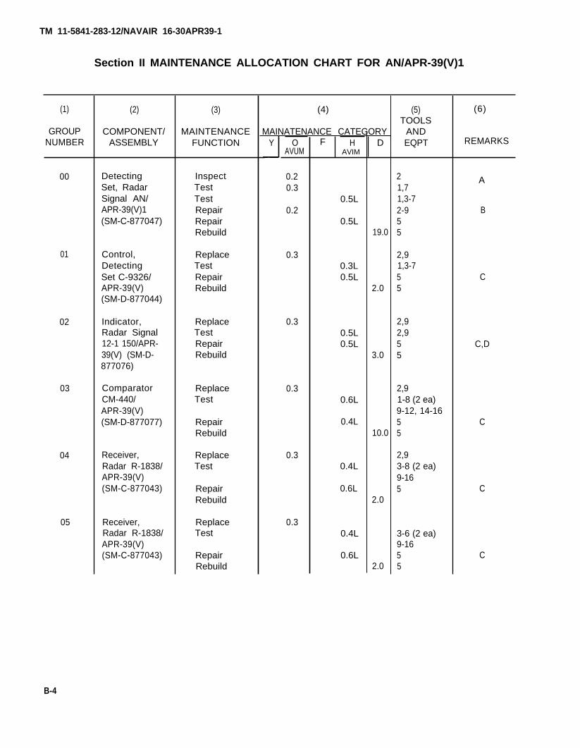
Section II MAINTENANCE ALLOCATION CHART FOR AN/APR-39(V)1
(1)
GROUPNUMBER
(4)
00
01
02
03
04
05
(2)
COMPONENT/ASSEMBLY
DetectingSet, RadarSignal AN/APR-39(V)1(SM-C-877047)
Control,DetectingSet C-9326/APR-39(V)(SM-D-877044)
Indicator,Radar Signal12-1 150/APR-39(V) (SM-D-877076)
ComparatorCM-440/APR-39(V)(SM-D-877077)
Receiver,Radar R-1838/APR-39(V)(SM-C-877043)
Receiver,Radar R-1838/APR-39(V)(SM-C-877043)
(3)
MAINTENANCEFUNCTION
InspectTestTestRepairRepairRebuild
ReplaceTestRepairRebuild
ReplaceTestRepairRebuild
ReplaceTest
RepairRebuild
ReplaceTest
RepairRebuild
ReplaceTest
RepairRebuild
Y OAVUM
0.20.3
0.2
0.3
0.3
0.3
0.3
0.3
HAVIM
0.5L
0.5L
0.3L0.5L
0.5L0.5L
0.6L
0.4L
0.4L
0.6L
0.4L
0.6L
D
19.0
2.0
3.0
10.0
2.0
2.0
(5)TOOLS
ANDEQPT
21,71,3-72-955
2,91,3-755
2,92,955
2,91-8 (2 ea)9-12, 14-1655
2,93-8 (2 ea)9-165
3-6 (2 ea)9-1655
B
C
C,D
C
C
C
B-4
FMAINATENANCE CATEGORY
A
TM 11-5841-283-12/NAVAIR 16-30APR39-1
REMARKS
(6)
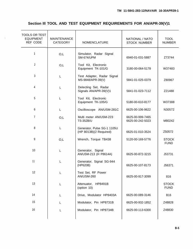
Section Ill TOOL AND TEST EQUIPMENT REQUIREMENTS FOR AN/APR-39(V)1
TOOLS OR TESTI EQUIPMENT
REF CODE
1
2
3
4
5
6
7
8
9
10
11
12
13
14
15
16
MAINTENANCECATEGORY
O,L
O,L
L
L
L
L
O,L
L
O,L
L
L
L
L
L
L
L
NOMENCLATURE
Simulator, Radar SignalSM-674/UPM
Tool Kit, ElectronicEquipment TK-101/G
Test Adapter, Radar SignalMS-9848/APR-39(V)
Detecting Set, RadarSignals AN/APR-39(V)1
Tool Kit, ElectronicEquipment TK-105/G
Oscilloscope AN/USM-281C
Multi meter AN/USM-223TS-352B/U
Generator, Pulse SG-1 1105U(HP 8013B)(2 Required)
Wrench, Torque TB438
Generator, SignalAN/USM-213 (H P8614A)
Generator, Signal SG-944(HP620B)
Test Set, RF PowerAN/USM-260
Attenuator, HP8491B(option 10)
Drive, Modulator HP8403A
Modulator, Pin HP8731B
Modulator, Pin HP8734B
NATIONAL / NATOSTOCK NUMBER
6940-01-031-5887
3180-00-064-5178
5841-01-025-0379
5841-01-023-7112
5180-00-610-8177
6625-00-106-9622
6625-00-999-74656625-00-242-5023
6625-01-010-3524
5120-00-169-5776
6625-00-872-3215
6625-00-107-8173
6625-00-917-3099
6625-00-089-3146
6625-00-932-1852
6625-00-113-6300
TOOLNUMBER
Z73744
W37483
Z80967
Z21488
W37388
N30572
M80242
Z50572
STOCKFUND
J53731
J56371
816
STOCKFUND
B16
Z48828
Z48830
B-5
TM 11-5841-283-12/NAVAIR 16-30APR39-1

TM 11-5841-283-12/NAVAIR 16-30APR39-1
TOOL AND TEST EQUIPMENT REQUIREMENTS FOR AN/APR-39(V)1 (CONT)
TOOLS OR TESTEQUIPMENT MAINTENANCEREF CODE CATEGORY
REFERENCECODE
A
B
C
D
NOMENCLATURE
Additional Items Required
RF connector EMA Male toUNC Female (2 required)
RF connector EMA Male toN Female (1 required)
RF connector BNC Male toTNC Plug
Thermistor Mount HP-478A
NATIONAL / NATOSTOCK NUMBER
5935-00-024-0612
3925-00-869-2405
5935-00-701-2215
6625-00-886-1955
TOOLN U M B E R
Section IV REMARKS
REMARKS
Test to isolate defective major components.
Repair by replacing defective repairable major assemblies, anddefective throw-away lamps, fuses and knobs. It should be notedthat a missile alert lamp in indicator, radar signal (Q2) is replacedAVIM only.
at
Defective printed circuit boards, have been determined to be throw-away and are to be sent back to depot for final disposition.
Defective power supply is not repairable.
B-6
TM 11-5841-283-12/NAVAIR 16-30APR39-1
APPENDIX C
COMPONENTS OF END ITEM AND BASIC ISSUE ITEMS LIST
Section I INTRODUCTION
C-1. SCOPE.
This appendix lists components of end item and basic issue items for the radar signal detectingset to help you inventory items required for safe and efficient operation.
C-2. GENERAL.
The components of end item and basic issue item lists are divided into the following sections:
a. Section II Components of End Item. This listing is for informational purposes only, and isnot authority to requisition replacements. These items are part of the end item, but are removedand separately packaged for transportation or shipment. As part of the end item, these itemsmust be with the end item whenever it is issued or transferred between property accounts.
b. Section Ill Basic Issue Items. These are the minimum essential items required to place theradar signal detecting set in operation, to operate it, and to perform emergency repairs.Although shipped separately packaged, Bll must be with the radar signal detecting set duringoperation and whenever it is transferred between property accounts. This manual is yourauthority to request/requisition replacement BII, based on TOE/MTOE authorization of the enditem.
C-3. EXPLANATION OF COLUMNS.
The following provides an explanation of columns found in the tabular listings:
a. Column 1, Illustration Number (Illus No.). This column does not apply.
b. Column 2, National Stock Number. Indicates the national stock number assigned to the itemand will be used for requisitioning purposes.
c. Column 3, Description. Indicates the federal item name and, if required, a minimumdescription to identify and locate the item. The last line for each item indicates the FSCM (inparentheses) followed by the part number.
d. Column 4, Unit of Measure (U/M). Indicates the measure used in performing the actualoperational/maintenance function. This measure is expressed by a two-character abbreviation(e.g., ea, in., pr).
e. Column 5, Quantity Required (Qty Req’d). Indicates the quantity of the item authorized tobe used with/on the equipment,
C-1
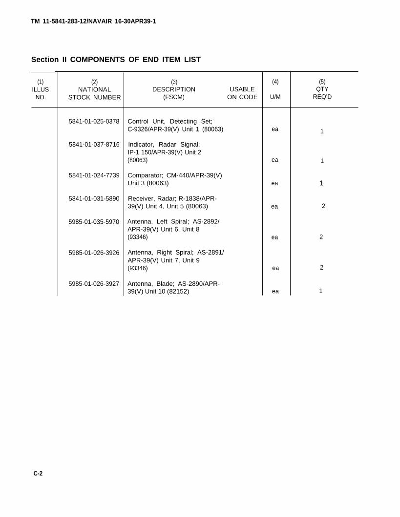
TM 11-5841-283-12/NAVAIR 16-30APR39-1
Section II COMPONENTS OF END ITEM LIST
(1)ILLUS
NO.
(2)NATIONAL
STOCK NUMBER
5841-01-025-0378
5841-01-037-8716
5841-01-024-7739
5841-01-031-5890
5985-01-035-5970
5985-01-026-3926
5985-01-026-3927
(3)DESCRIPTION USABLE
(FSCM) ON CODE
Control Unit, Detecting Set;C-9326/APR-39(V) Unit 1 (80063)
Indicator, Radar Signal;IP-1 150/APR-39(V) Unit 2(80063)
Comparator; CM-440/APR-39(V)Unit 3 (80063)
Receiver, Radar; R-1838/APR-39(V) Unit 4, Unit 5 (80063)
Antenna, Left Spiral; AS-2892/APR-39(V) Unit 6, Unit 8(93346)
Antenna, Right Spiral; AS-2891/APR-39(V) Unit 7, Unit 9(93346)
Antenna, Blade; AS-2890/APR-39(V) Unit 10 (82152)
(4)
U/M
ea
ea
ea
ea
ea
ea
ea
(5)QTY
REQ’D
C-2
2
2
2
1
1
1
1
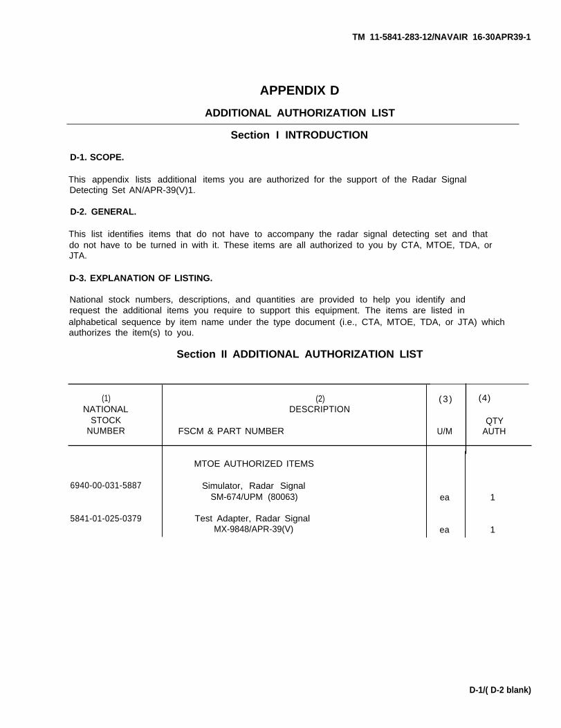
TM 11-5841-283-12/NAVAIR 16-30APR39-1
APPENDIX D
ADDITIONAL AUTHORIZATION LIST
D-1. SCOPE.
This appendix lists additional itemsDetecting Set AN/APR-39(V)1.
D-2. GENERAL.
This list identifies items that do not
Section I INTRODUCTION
you are authorized for the support of the Radar Signal
have to accompany the radar signal detecting set and thatdo not have to be turned in with it. These items are all authorized to you by CTA, MTOE, TDA, orJTA.
D-3. EXPLANATION OF LISTING.
National stock numbers, descriptions, and quantities are provided to help you identify andrequest the additional items you require to support this equipment. The items are listed inalphabetical sequence by item name under the type document (i.e., CTA, MTOE, TDA, or JTA) whichauthorizes the item(s) to you.
Section II ADDITIONAL AUTHORIZATION LIST
(1)NATIONAL
STOCKNUMBER
6940-00-031-5887
5841-01-025-0379
(2)DESCRIPTION
FSCM & PART NUMBER
MTOE AUTHORIZED ITEMS
Simulator, Radar SignalSM-674/UPM (80063)
Test Adapter, Radar SignalMX-9848/APR-39(V)
QTYU/M AUTH
ea
ea
1
1
D-1/( D-2 blank)
(3 ) (4)
TM 11-5841-283-12/NAVAIR 16-30APR39-1
APPENDIX E
EXPENDABLE SUPPLIES AND MATERIALS LIST
Section I INTRODUCTION
E-1. SCOPE.
This appendix lists expendable supplies and materials you will need to operate and maintainRadar Signal Detecting Set AN/APR-39(V)1. These items are authorized to you by CTA 50-970,Expendable items (except medical, class V, repair parts, and heraldic items).
E-2. EXPLANATION OF COLUMNS.
the
a. Column 1, Item Number. This number is assigned to the entry in the listing and isreferenced in the narrative instructions to identify the material (e.g., use cleaning compound,item 1, appendix E).
b. Column 2, Level. This column identifies the lowest level of maintenance that requires thelisted item.
C - Operator/CrewO - OrganizationalF - Direct SupportH - General Support
c. Column 3, National Stock Number. This is the national stock number assigned to the item;use it to request or requisition the item.
d. Column 4, Description. Indicates the federal item name and, if required, a description toidentify the item. The last line for each item indicates the Federal Supply Code forManufacturer (FSCM) in parentheses, if applicable.
e. Column 5, Unit of Measurement (U/M). Indicates the measure used in performing the actualmaintenance function. This measure is expressed by a two-character abbreviation (e.g., ea, in.,pr). If the unit of measure differs from the unit of issue, requisition the lowest unit of issuethat will satisfy your requirements.
E-1
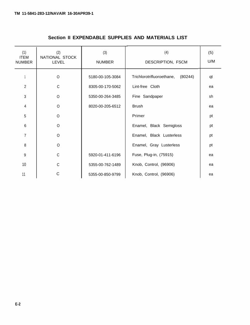
TM 11-5841-283-12/NAVAlR 16-30APR39-1
(1)ITEM
NUMBER
1
2
3
4
5
6
7
8
9
10
11
Section II EXPENDABLE SUPPLIES AND MATERIALS LIST
(2)NATIONAL STOCK
LEVEL
O
C
O
O
O
O
O
O
C
C
(3)
NUMBER
5180-00-105-3084
8305-00-170-5062
5350-00-264-3485
8020-00-205-6512
5920-01-411-6196
5355-00-762-1489
5355-00-850-9799
(4)
DESCRIPTION, FSCM
Trichlorotrifluoroethane, (80244)
Lint-free Cloth
Fine Sandpaper
Brush
Primer
Enamel, Black Semigloss
Enamel, Black Lusterless
Enamel, Gray Lusterless
Fuse, Plug-in, (75915)
Knob, Control, (96906)
Knob, Control, (96906)
qt
ea
sh
ea
pt
pt
pt
pt
ea
ea
ea
E-2
C
(5)
U/M
TM 11-5841-283-12
GLOSSARY
The following special words and terms are used in this manual.
ALARM AUDIO. A varying high-low warning tone sounded at a 2.5 Hz rate. Alarm sounds with afrequency of 1100 Hz and stops with a frequency of 700 Hz.
CRT (cathode ray tube). Radar signal indicator screen. Shows aircraft operator the presence ofa signal.
LINE-OF-BEARING. A direction to an emitter or tracking device with respect to aircraft heading.Direction is displayed by a radial strobe on the indicator CRT.
PERSISTENCE. The number of pulses present in a pulse train in a specified period of time.Persistence is expressed as a percentage.
PULSE. An abrupt change in voltage (either positive or negative), which conveys information to acircuit.
PULSE CORRELATION. The time relationship between pulses of high band and low band intercepts.Pulses are correlated when the low band trailing edge leads the high band leading edge by aspecified time.
PULSE REPETITION FREQUENCY (PRF). The audio tone generated by mixing the high band videos.
PULSE REPETITION INTERVAL (PRI). Also known as pulse repetition period (PRP). The interval orperiod expressed as a unit of time, between the leading edges of sequential pulses in a train.
PRI=1/PRF
PULSE TRAIN. A repetition of pulses.
Glossary 1/(Glossary 2 Blank)
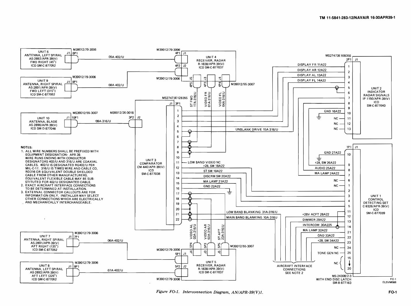
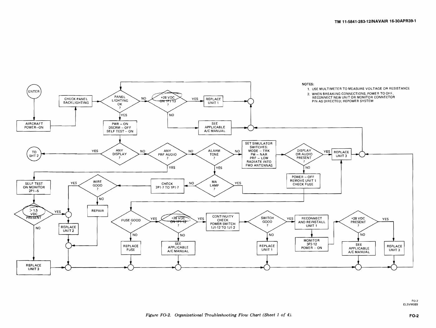
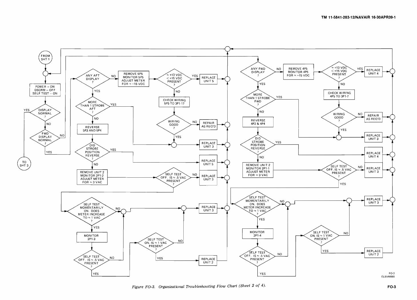
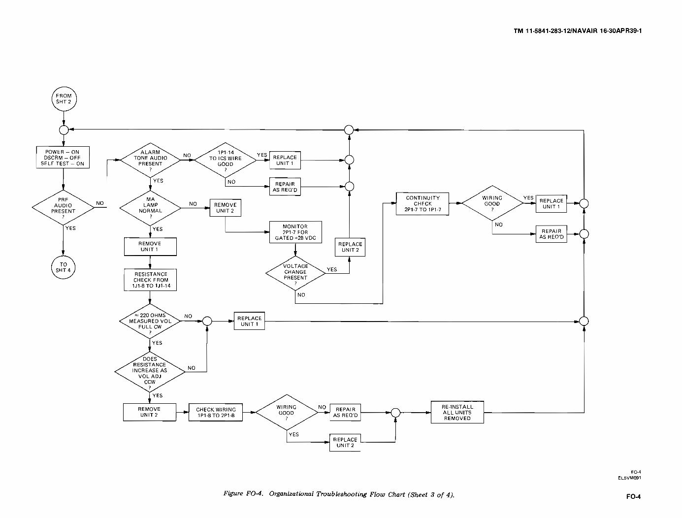
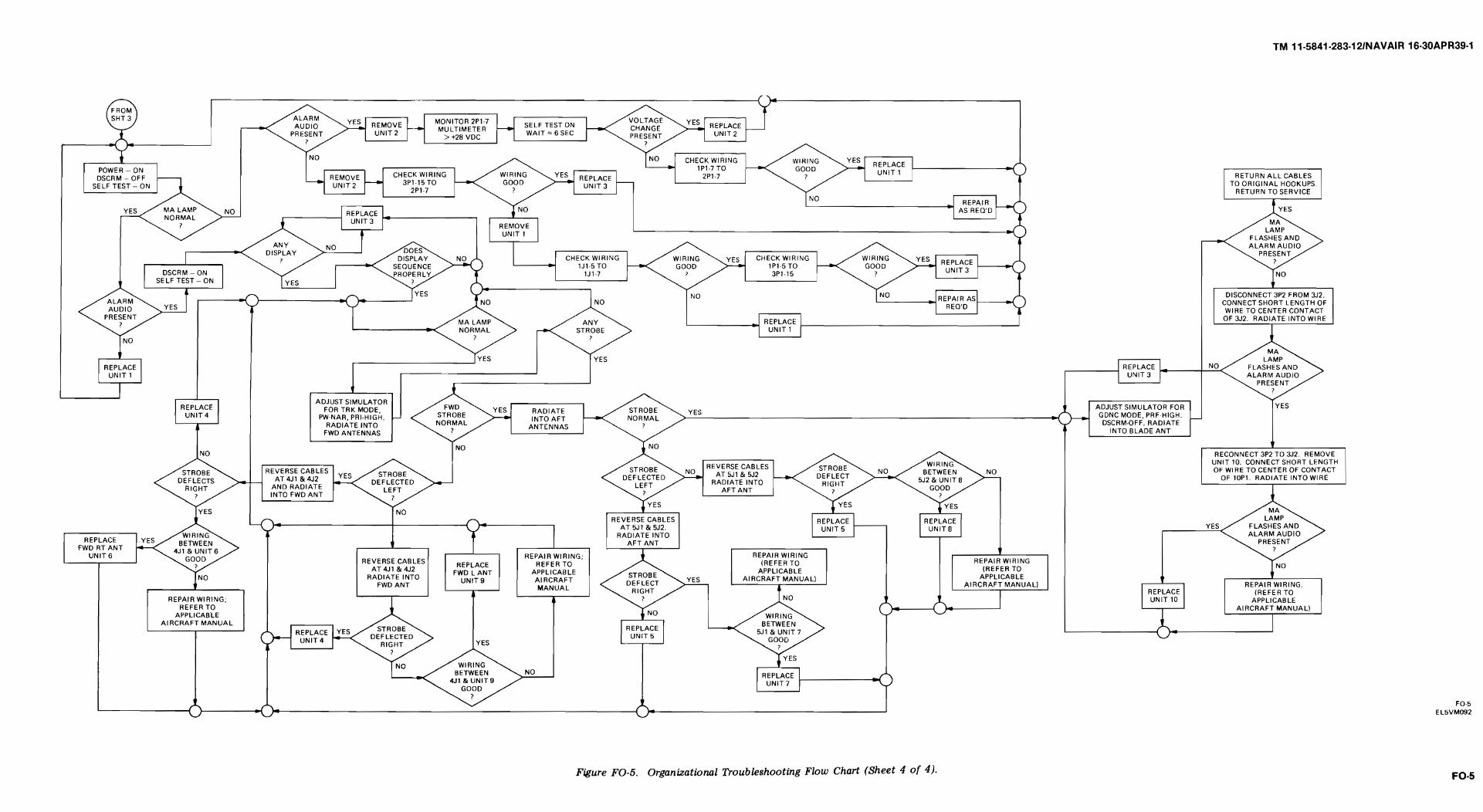
TM 11-5841-283-12/NAVAIR 16-30APR39-1
INDEX
A
AbbreviationsAntennas ,blade,
. . . . . . . . . . . . . . . . . . . . . . . . . . . . . . . . . . . . . . . . . . . . . . . . . . . . . . . . . . . . . . . . . . . . . . .
cleaning of . . . . . . . . . . . . . . . . . . . . . . . . . . . . . . . . . . . . . . . . . . . . . . . . . . . . . . . . . . . . . . . . . . . . . .description of . . . . . . . . . . . . . . . . . . . . . . . . . . . . . . . . . . . . . . . . . . . . . . . . . . . . . . . . . . . . . . . . . . . .painting of . . . . . . . . . . . . . . . . . . . . . . . . . . . . . . . . . . . . . . . . . . . . . . . . . . . . . . . . . . . . . . . . . . . . . .replacement of . . . . . . . . . . . . . . . . . . . . . . . . . . . . . . . . . . . . . . . . . . . . . . . . . . . . . . . . . . . . . . . . . .
spiral,cleaning of . . . . . . . . . . . . . . . . . . . . . . . . . . . . . . . . . . . . . . . . . . . . . . . . . . . . . . . . . . . . . . . . . . . . . .description of... . . . . . . . . . . . . . . . . . . . . . . . . . . . . . . . . . . . . . . . . . . . . . . . . . . . . . . . . . . . . . . . . .painting of . . . . . . . . . . . . . . . . . . . . . . . . . . . . . . . . . . . . . . . . . . . . . . . . . . . . . . . . . . . . . . . . . . . . . .replacement of . . . . . . . . . . . . . . . . . . . . . . . . . . . . . . . . . . . . . . . . . . , . . . . . . . . . . . . . . . . . . . . . . . .troubleshooting of . . . . . . . . . . . . . . . . . . . . . . . . . . . . . . . . . . . . . . . . . . . . . . . . . . . . . . . . . . . . . . . .
Aviation unit,maintenance . . . . . . . . . . . . . . . . . . . . . . . . . . . . . . . . . . . . . . . . . . . . . . . . . . . . . preventive maintenance checks and services, . . . . . . . . . . . . . . . . . . . . . . . . . . . . . . . . . . . . . . . . . .blade antenna.. . . . . . . . . . . . . . . . . . . . . . . . . . . . . . . . . . . . . . . . . . . . . . . . . . . . . . . . . . . . . . . . . . .comparator. . . . . . . . . . . . . . . . . . . . . . . . . . . . . . . . . . . . . . . . . . . . . . . . . . . . . . . . . . . . . . . . . . . . . .control unit . . . . . . . . . . . . . . . . . . . . . . . . . . . . . . . . . . . . . . . . . . . . ...... . . . . . . . .radar receivers . . . . . . . . . . . . . . . . . . . . . . . . . . . . . . . . . . . . . . . . . . . . . . . . . . . . . . . . . . . . . . . . . . .radar signal indicator . . . . . . . . . . . . . . . . . . . . . . . . . . . . . . . . . . . . . . . . . . . . . . . . . . . . . . . . . . . . .spiral antennas . . . . . . . . . . . . . . . . . . . . . . . . . . . . . . . . . . . . . . . . . . . . . . . . . . . . . . . . . . . . . . . . . .
B
1-3
4-451-54-804-46
4-451-54-904-644-44
4-14-334-394-364-344-374-354-38
Blade antenna,cleaning of . . . . . . . . . . . . . . . . . . . . . . . . . . . . . . . . . . . . . . . . . . . . . . . . . . . . . . . . . . . . . . . . . . . . . . . 4-45description of. . . . . . . . . . . . . . . . . . . . . . . . . . . . . . . . . . . . . . . . . . . . . . . . . . . . . . . . . 1-5painting of . . . . . . . . . . . . . . . . . . . . . . . . . . . . . . . . . . . . . . . . . . . . . . . . . . . . . . 4-80replacement of . . . . . . . . . . . . . . . . . . . . . . . . . . . . . . . . . . . . . . . . . . . . . . . . . . . . . . . . . . . . . . . . . . . . 4-47
Block diagram presentation . . . . . . . . . . . . . . . . . . . . . . . . . . . . . . . . . . . . . . . . . . . . . . . . . . . . . . . . . . 1-10
C
Cable connections . . . . . . . . . . . . . . . . . . . . . . . . . . . . . . . . . . . . . . . . . . . . . . . . . . . . . . . . . . . . . . . . . .Capabilities and features . . . . . . . . . . . . . . . . . . . . . . . . . . . . . . . . . . . . . . . . . . . . . . . . . . . . . . . . . . . .Checking unpacked material . . . . . . . . . . . . . . . . . . . . . . . . . . . . . . . . . . . . . . . . . . . . . . . . . . . . . . . . .Cleaning components . . . . . . . . . . . . . . . . . . . . . . . . . . . . . . . . . . . . . . . . . . . . . . .Common tools and equipment . . . . . . . . . . . . . . . . . . . . . . . . . . . . . . . . . . . . . . . . . . . . . . . . . . . . . . . .Comparator,cleaning of . . . . . . . . . . . . . . . . . . . . . . . . . . . . . . . . . . . . . . . . . . . . . . . . . . . . . . . . . . . . . . . . . . . . .description of . . . . . . . . . . . . . . . . . . . . . . . . . . . . . . . . . . . . . . . . . . . . . . . . . . . . . . . . . . . . .painting of . . . . . . . . . . . . . . . . . . . . . . . . . . . . . . . . . . . . . . . . . . . . . . . . . . . . . . . . . . . . . . . . . . . . .replacement of . . . . . . . . . . . . . . . . . . . . . . . . . . . . . . . . . . . . . . . . . . . . . . . . . . . . . . . . . . . . . . . . . .
Control unit,audio control knob replacement . . . . . . . . . . . . . . . . . . . . . . . . . . . . . . . . . . . . . . . . . . . . . . . . . . . . . .cleaning of . . . . . . . . . . . . . . . . . . . . . . . . . . . . . . . . . . . . . . . . . . . . . . . . . . . . . . . . . . . . . . . . . . . . . . .description of . . . . . . . . . . . . . . . . . . . . . . . . . . . . . . . . . . . . . . . . . . . . . . . . . . . . . . . . . . . . . .
4-101-44-44-454-1
4-451-54-824-48
4-684-451-6
Index 1
Sub jec t Page
TM 11-5841-283-12/NAVAIR 16930APR39-1
INDEX (CONT)
C (CONT)
fuse replacement . . . . . . . . . . . . . . . . . . . . . . . . . . . . . . . . . . . . . . . . . . . . . . 4-70Iighting panel replacement . . . . . . . . . . . . . . . . . . . . . . . . . . . . . . . . . . . . . . . . . . . . . . . . . . . . . . . . . . 4-74painting of . . . . . . . . . . . . . . . . . . . . . . . . . . . . . . . . . . . . . . . . . . . . . . . . . . . . . . . . . . . . . . 4-84replacement of . . . . . . . . . . . . . . . . . . . . . . . . . . . . . . . . . . . . . . . . . . . . . . . . . . . . . . 4-52switch guard plate replacement . . . . . . . . . . . . . . . . . . . . . . . . . . . . . . . . . . . . . . . . . . . . . . . . . . . . . . 4-78
D
Destruction of army electronics materiel . . . . . . . . . . . . . . . . . . . . . . . . . . . . . . . . . . . . . . . . . . . . . . . 1-2Description and use of operator’s controls and indicators . . . . . . . . . . . . . . . . . . . . . . . . . . . . . . . . . 2-1Discrepancy in shipment report . . . . . . . . . . . . . . . . . . . . . . . . . . . . . . . . . . . . . . . . . . . . . 1-2Discriminator mode selection . . . . . . . . . . . . . . . . . . . . . . . . . . . . . . . . . . . . . . . . . . . . . . . . . . . . . . . . . 2-1
E
Equipment,characteristics . . . . . . . . . . . . . . . . . . . . . . . . . . . . . . . . . . . . . . . . . . . . . . . . . . . . . . . . . . . . . . 1-4covered in manual . . . . . . . . . . . . . . . . . . . . . . . . . . . . . . . . . . . . . . . . . . . . . . . . . . . 1-1data . . . . . . . . . . . . . . . . . . . . . . . . . . . . . . . . . . . . . . . . . . . . . . . . . . . . . . . . . . . 1-7
F
Fuse replacement . . . . . . . . . . . . . . . . . . . . . . . . . . . . . . . . . . . . . . . . . . . . . . . . . . . . . . 4-70
Initial installation of equipment . . . . . . . . . . . . . . . . . . . . . . . . . . . . . . . . . . . 4-4Installation of plug-in itemsIntroduction . . . . . . . . . . . . .
4-11. . . . . . . . . . . . . . . . . . . . . . . . . . . . . . . . . . . . . . . . 1-1. . . . . . . . . . . . . . . . . . . . . . . . . . . . . . . . . . . . . . .
L
Left spiral antennas,cleaning of . . . . . . . . . . . . . . . . . . . . . . . . . . . . . . . . . . . . . . . . . . . . . . . . . . . . . . . . . . . . . . . . . . . 4-45description of . . . . . . . . . . . . . . . . . . . . . . . . . . . . . . . . . . . . . . . . . . . . 1-6painting of . . . . . . . . . . . . . . . . . . . . . . . . . . . . . . . . . . . . . . . . . . . . . . . . . . . . . . . . . 4-90replacement of. . . . . . . . . . . . . . . . . . .. . . . . . . . . . . . . . . . . . . . . . . . . . . . . . . . . . . . . . . . . . . . . . 4-64troubleshooting of . . . . . . . . . . . . . . . . . . . . . . . . . . . . . . . . . . . . . . . . . . . . . . . . . . . . . . . . . . . . . . . . . 4-44
Lighting panel,replacement of . . . . . . . . . . . . . . . . . . . . . . . . . . . . . . . . . . . . . . . . . . . . . . . . . . . . . . . . . . . . . 4-74
Location and escriptionof major components . . . . . . . . . . . . . . . . . . . . . . . . . . . . . . . . . . . . . . . . . . 1-5
M
Maintenance forms, records, and reports . . . . . . . . . . . . . . . . . . . . . . . . . . . . . . . . . . . . . . . . . . . . . . . 1-2Maintenance procedures,aviation unit . . . . . . . . . . . . . . . . . . . . . . . . . . . . . . . . . . . . . . . . . . . . . . . . . . . . . . . . . . . 4-45
Index 2
I
Subject Page
TM 11-5841-283-12/NAVAIR 16-30APR39-1
INDEX (CONT)
Subject
N
Nomenclature cross-reference list . . . . . . . . . . . . . . . . . . . . . . . . . . . . . . . . . . . . . . . . . . . . . . . . . . . . . 1-3
0
Operating instructions . . . . . . . . . . . . . . . . . . . . . . . . . . . . . . . . . . . . . . . . . . . . . . . . . . . . . . . . . . . . . . 2-1Operation under usual conditions . . . . . . . . . . . . . . . . . . . . . . . . . . . . . . . . . . . . . . . . . . . . . . . . . . . . . 2-3
P
Packing . . . . . . . . . . . . . . . . . . . . . . . . . . . . . . . . . . . . . . . . . . . . . . . . . . . . . . . . . . . . . . . . . . . . . . . . . . .Painting, . . . . . . . . . . . . . . . . . . . . . . . . . . . . . . . . . . . . . . . . . . . . . . . . . . . . . . . . . . . . . . . . . . . . . . . . . .blade antenna.. . . . . . . . . . . . . . . . . . . . . . . . . . . . . . . . . . . . . . . . . . . . . . . . . . . . . . . . . . . . . . . . . . . .comparator, . . . . . . . . . . . . . . . . . . . . , . . . . . . . . . . . . . . . . . . . . . . . . . . . . . . . . . . . . . . . . . . . . . . . . .control unit . . . . . . . . . . . . . . . . . . . . , , . . . . . . . . . . . . . . . . . . . . . . . . . . . . . . . . . . . . . . . . . . . . . . . . .radar receivers . . . . . . . . . . . . . . . . . . , . . . . . . . . . . . . . . . . . . . . . . . . . . . . . . . . . . . . . . . . . . . . . . . . .radar signal indicator . . . . . . . . . . . . . . . . . . . . . . . . . . . . . . . . . . . . . . . . . . . . . . . . . . . . . . . . . . . . . .spiral antennas . . . . . . . . . . . . . . . . . . . . . . . . . . . . . . . . . . . . . . . . . . . . . . . . . . . . . . . . . . . . . . . . . . .
Preliminary servicing and adjustment of equipment. . . . . . . . . . . . . . . . . . . . . . . . . . . . . . . . . . . . . . .Preparation for storage or shipment . . . . . . . . . . . . . . . . . . . . . . . . . . . . . . . . . . . . . . . . . . . . . . . . . . .Preventive maintenance checks and services,
aviation unit . . . . . . . . . . . . . . . . . . . . . . . . . . . . . . . . . . . . . . . . . . . . . . . . . . . . . . . . . . . . . . . . . . . . . .Purpose of equipment . . . . . . . . . . . . . . . . . . . . . . . . . . . . . . . . . . . . . . . . . . . . . . . . . . . . . . . . . . . . . . .
R
Radar receivers,cleaning of . . . . . . . . . . . . . . . . . . . . . . . . . . . . . . . . . . . . . . . . . . . . . . . . . . . . . . . . . . . . . . . . . . . . . . .description of . . . . . . . . . . . . . . . . . . . . . . . . . . . . . . . . . . . . . . . . . . . . . . . . . . . . . . . . . . . . . . . . . . . . .painting of . . . . . . . . . . . . . . . . . . . . . . . . . . . . . . . . . . . . . . . . . . . . . . . . . . . . . . . . . . . . . . . . . . . . . . .replacement of . . . . . . . . . . . . . . . . . . . . . . . . . . . . . . . . . . . . . . . . . . . . . . . . . . . . . . . . . . . . . . . . . . . .
Radar signal indicator,cleaning of . . . . . . . . . . . . . . . . . . . . . . . . . . . . . . . . . . . . . . . . . . . . . . . . . . . . . . . . . . . . . . . . . . . . . . .description of. . . . . . . . . . . . . . . . . . . . . . . . . . . . . . . . . . . . . . . . . . . . . . . . . . . . . . . . . . . . . . . . . . . .painting of . . . . . . . . . . . . . . . . . . . . . . . . . . . . . . . . . . . . . . . . . . . . . . . . . . . . . . . . . . . . . . . . . . .replacement of . . . . . . . . . . . . . . . . . . . . . . . . . . . . . . . . . . . . . . . . . . . . . . . . . . . . . . . . . . . . . . . . . . . .troubleshooting of,
aviation unit . . . . . . . . . . . . . . . . . . . . . . . . . . . . . . . . . . . . . . . . . . . . . . . . . . . . . . . . . . . . . . . . . . . . .Repair parts, special tools, TMDE, and support equipment . . . . . . . . . . . . . . . . . . . . . . . . . . . . . . . . .Report of packaging and handling deficiencies . . . . . . . . . . . . . . . . . . . . . . . . . . . . . . . . . . . . . . . . . .Reporting equipment improvement recommendations. . . . . . . . . . . . . . . . . . . . . . . . . . . . . . . . . . . . .Reports of maintenance and unsatisfactory equipment . . . . . . . . . . . . . . . . . . . . . . . . . . , . . . , . . . .Replacement, . . . . . . . . . . . . . . . . . . . . . . . . . . . . . . . . . . . . . . . . . . . . . . . . . . . . . . . . . . . . . . . . . . . . . .blade antenna . . . . . . . . . . . . . . . . . . . . . . . . . . . . . . . . . . . . . . . . . . . . . . . . . . . . . . . . . . . . . . . . . . . . .comparator. . . . . . . . . . . . . . . . . . . . . . . . . . . . . . . . . . . . . . . . . . . . . . . . . . . . . . . . . . . . . . . . . ...,
4-924-804-804-824-844-864-884-904-111-2
4-341-1
4-451-54-864-56
4-451-54-884-60
4-424-11-21-21-24-464-464-48
Index 3
Page

TM 11-5841-283-12/NAVAIR 16-30APR399-1
INDEX (CONT)
R (CONT)
control unit . . . . . . . . . . . . . . . . . . . . . . . . . . . . . . . . . . . . . . . . . . . . . . . . . . . . . . . . . . . . . . . . . . . . . . . 4-52audio control knob. . . . . . . . . . . . . . . . . . . . . . . . . . . . . . . . . . . . . . . . . . . . . . . . . . . . . . . . . . . . . . . 4-68fuse . . . . . . . . . . . . . . . . . . . . . . . . . . . . . . . . . . . . . . . . . . . . . . . . . . . . . . . . . . . . . . . . . . . . . . . . . . . . . 4-70Iighting panel . . . . . . . . . . . . . . . . . . . . . . . . . . . . . . . . . . . . . . . . . . . . . . . . . . . . . . . . . . . . . . . . . . . . 4-74switch guard plate . . . . . . . . . . . . . . . . . . . . . . . . . . . . . . . . . . . . . . . . . . . . . . . . . . . . . . . . . . . . . . . 4-78radar receivers . . . . . . . . . . . . . . . . . . . . . . . . . . . . . . . . . . . . . . . . . . . . . . . . . . . . . . . . . . . . . . . . . . . . 4-56radar signal indicator . . . . . . . . . . . . . . . . . . . . . . . . . . . . . . . . . . . . . . . . . . . . . . . . . . . . . . . . . . 4-60spiral antennas . . . . . . . . . . . . . . . . . . . . . . . . . . . . . . . . . . . . . . . . . . . . . . . . . . . . . . . . . . . . . . . . . . 4-64
Right spiral antenna,cleaning of . . . . . . . . . . . . . . . . . . . . . . . . . . . . . . . . . . . . . . . . . . . . . . . . . . . . . . . . . . . . . . . . . . . . . 4-45description of . . . . . . . . . . . . . . . . . . . . . . . . . . . . . . . . . . . . . . . . . . . . . . . . . . . . . . . . . . . . . . . . . . . . . 1-5painting of . . . . . . . . . . . . . . . . . . . . . . . . . . . . . . . . . . . . . . . . . . . . . . . . . . . . . . . . . . . . . . . . 4-90replacement of . . . . . . . . . . . . . . . . . . . . . . . . . . . . . . . . . . . . . . . . . . . . . . . . . . . . . . . . . . . . . . . . . . . . 4-64troubleshooting of. . . . . . . . . . . . . . . . . . . . . . . . . . . . . . . . . . . . . . . . . . . . . . . . . . . . . . . . . . . . . . 4-44
S
T
Troubleshootingaviation unit . . . . . . . . . . . . . . . . . . . . . . . . . . . . . . . . . . . . . . . . . . . . . . . . . . . . . . . . . . . . 4-41radar signal indicator . . . . . . . . . . . . . . . . . . . . . . . . . . . . . . . . . . . . . . . . . . . . . . . 4-42spiral antennas . . . . . . . . . . . . . . . . . . . . . . . . . . . . . . . . . . . . . . . . . . . . . . . 4-44
Turn-on procedure . . . . . . . . . . . . . . . . . . . . . . . . . . . . . . . . . . . . . . . . . . . . . . 2-3
U
Unpacking . . . . . . . . . . . . . . . . .. . . . . . . . . . . . . . . . . . . . . . . . . . . . . . . . .... . . . . . . . . . . 4-2
Index 4
Subject Page
Safety, care, and handling . . . . . . . . . . . . . . . . . . . . . . . . . . . . . . . . . . . . . . . . . . . . . . . . . . . . . . . . . . . . . . . . . . . . . . . . . . 1-10Self-test. . . . . . . . . . . . . . . . . . . . . . . .. . . . . . . . . . . . . . . . . . . . . . . . . . . . . . . . . . . . . . . . . . . . . . . . . . . . . . . . . . . . . . . . 2-6Service upon receipt . . . . . . . . . . . . . . . . . . . . . . . . . . . . . . . . . . . . . . . . . . . . . . . . . . . . . . . . . . . . . . . . . . . . . . . . . . . . . . 4-2Shutdown procedures . . . . . . . . . . . . . . . . . . . . . . . . . . . . . . . . . . . . . . . . . . . . . . . . . . . . . . . . . . . . . . . . . . . . . . . . . . . . . . 2-14Spiral antennas,cleaning of. . . . . . . . . . . . . . . . . . . . . . . . . . . . . . . . . . . . . . . . . . . . . . . . . . . . . . . . . . . . . . . . . . . . . . . . . . . . . . . . . . .4-45description of . . . . . . . . . . . . . . . . . . . . . . . . . . . . . . . . . . . . . . . . . . . . . . . . . . . . . . . . . . . . . . . . . . . . . . . . . . . . . . . . . . . 1-5painting of . . . . . . . . . . . . . . . . . . . . . . . . . . . . . . . . . . . . . . . . . . . . . . . . . . . . . . . . . . . . . . . . . . . . . . . . . . . . . . . . . . . . 4-90replacement of . . . . . . . . . . . . . . . . . . . . . . . . . . . . . . . . . . . . . . . . . . . . . . . . . . . . . . . . . . . . . . . . . . . . . . . . . . 4-64troubleshooting of . . . . . . . . . . . . . . . . . . . . . . . . . . . . . . . . . . . . . . . . . . . . . . . . . . . . . . . . . . . . . . . . . . 4-44Switch guard plate replacement . . . . . . . . . . . . . . . . . . . . . . . . . . . . . . . . . . . . . . . . . . . . . . . . . . . . . . . 4-78System function test . . . . . . . . . . . . . . . . . . . . . . . . . . . . . . . . . . . . . . . . . .. . . . . . . . . . . . . . . . . . . . 4-11
By Order of the Secretary of the Army and the Navy:
Official:
JOHN A. WICKHAM, JR.General, United States Army
Chief of Staff
ROBERT M. JOYCEMajor General, United States Army
The Adjutant General
G. B. SHICKRear Admiral, United States Navy
Commander, Naval ElectronicSystems Command
Distribution:
To be distributed in accordance with DA Form 12-31, Operator’s Maintenancerequirements for AH-lG; CH-47A; CH-47B/C; OH-58; UH-lB; UH-lC/M;UH-lD/H and UH-60A.
U S GOVERNMENT PRINTING OFFICE 1983-605040237
REVERSE OF DA FORM 2028-2
C o m m a n d e r
US Army Communications-Electronics Command
and Fort Monmouth
ATTN: DRSEL-ME-MP
Fort Monmouth, New Jersey 07703
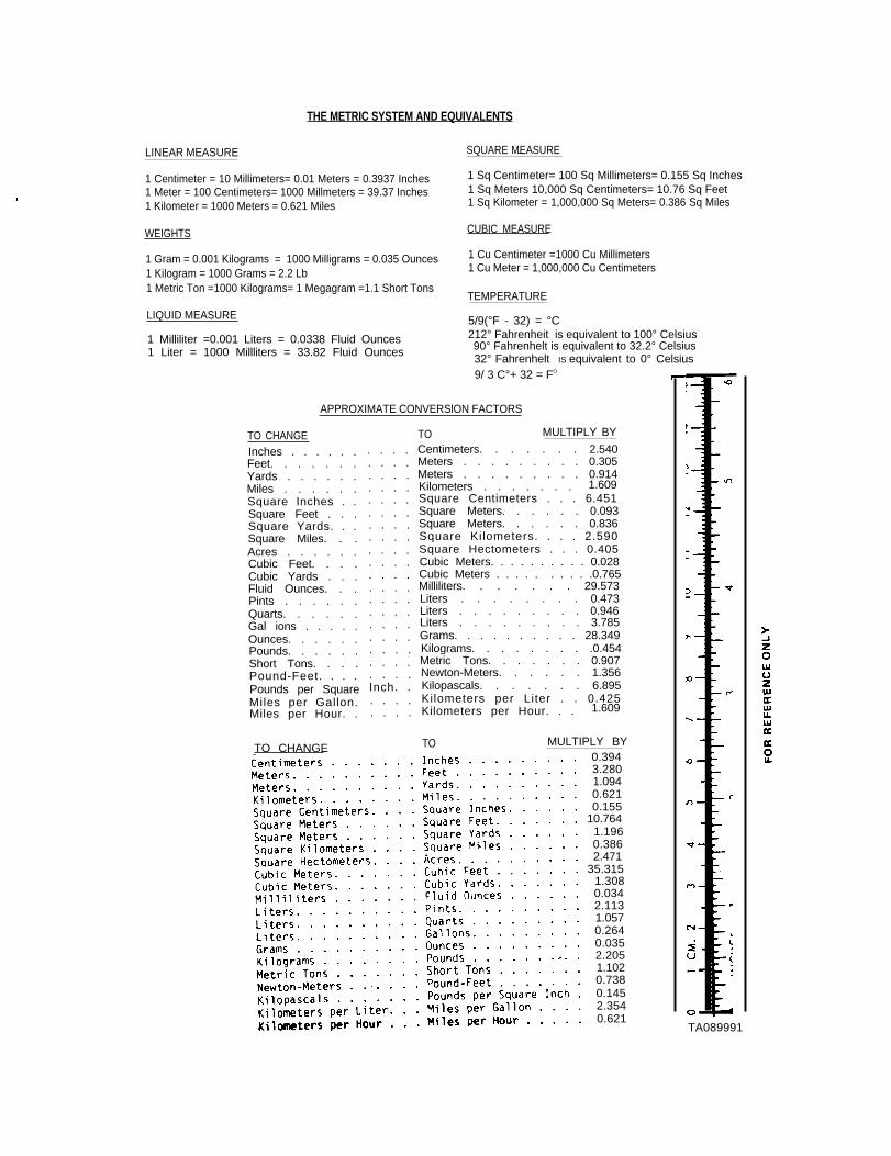
THE METRIC SYSTEM AND EQUIVALENTS
LINEAR MEASURE SQUARE MEASURE—
1 Centimeter = 10 Millimeters= 0.01 Meters = 0.3937 Inches 1 Sq Centimeter= 100 Sq Millimeters= 0.155 Sq Inches
1 Meter = 100 Centimeters= 1000 Millmeters = 39.37 Inches 1 Sq Meters 10,000 Sq Centimeters= 10.76 Sq Feet
1 Kilometer = 1000 Meters = 0.621 Miles 1 Sq Kilometer = 1,000,000 Sq Meters= 0.386 Sq Miles
WEIGHTS CUBIC MEASURE
1 Gram = 0.001 Kilograms = 1000 Milligrams = 0.035 Ounces 1 Cu Centimeter =1000 Cu Millimeters
1 Kilogram = 1000 Grams = 2.2 Lb 1 Cu Meter = 1,000,000 Cu Centimeters
1 Metric Ton =1000 Kilograms= 1 Megagram =1.1 Short TonsTEMPERATURE
LIQUID MEASURE 5/9(°F - 32) = °C
1 Milliliter =0.001 Liters = 0.0338 Fluid Ounces 212° Fahrenheit is equivalent to 100° Celsius
1 Liter = 1000 Millliters = 33.82 Fluid Ounces 90° Fahrenhelt is equivalent to 32.2° Celsius32° Fahrenhelt IS equivalent to 0° Celsius9/ 3 C°+ 32 = FO
APPROXIMATE CONVERSlON FACTORS
TO CHANGEInches . . . . . .Feet. . . . . . .Yards . . . . . .Miles . . . . . .Square Inches . .Square Feet . . .Square Yards. . .Square Miles. . .Acres . . . . . .Cubic Feet. . . .Cubic Yards . . .Fluid Ounces. . .Pints . . . . . .Quarts. . . . . .Gal ions . . . . .Ounces. . . . . .Pounds. . . . . .Short Tons. . . .Pound-Feet. . . .Pounds per SquareMiles per Gallon.Miles per Hour. .
. . . .
. . . .
. . . .
. . . .
. . . .
. . . .
. . . .
. . . .
. . . .
. . . .
. . . .
. . . .
. . . .
. . . .
. . . .
. . . .
. . . .
. . . .
. . . .Inch. .. . . .. . . .
TO MULTIPLY BY
Centimeters. . . . . . . 2.540Meters . . . . . . . . . 0.305Meters . . . . . . . . . 0.914Kilometers . . . . . . . 1.609Square Centimeters . . . 6.451Square Meters. . . . . . 0.093Square Meters. . . . . . 0.836Square Kilometers. . . . 2.590Square Hectometers . . . 0.405Cubic Meters. . . . . . . . . . 0.028Cubic Meters . . . . . . . . . .0.765Milliliters. . . . . . . 29.573Liters . . . . . . . . 0.473Liters . . . . . . . . . 0.946Liters . . . . . . . . . 3.785Grams. . . . . . . . . . 28.349Kilograms. . . . . . . . .0.454Metric Tons. . . . . . . 0.907Newton-Meters. . . . . . 1.356Kilopascals. . . . . . . 6.895Kilometers per Liter . . 0.425Kilometers per Hour. . . 1.609
TO MULTIPLY BY0.3943.2801.0940.6210.155
10.7641.1960.3862.471
35.3151.3080.0342.1131.0570.2640.0352.2051.1020.7380.1452.3540.621
TA089991
TO CHANGE

PIN: 053495-000

This fine document...
Was brought to you by me:
Liberated Manuals -- free army and government manuals
Why do I do it? I am tired of sleazy CD-ROM sellers, who take publicly available information, slap “watermarks” and other junk on it, and sell it. Those masters of search engine manipulation make sure that their sites that sell free information, come up first in search engines. They did not create it... They did not even scan it... Why should they get your money? Why are not letting you give those free manuals to your friends?
I am setting this document FREE. This document was made by the US Government and is NOT protected by Copyright. Feel free to share, republish, sell and so on.
I am not asking you for donations, fees or handouts. If you can, please provide a link to liberatedmanuals.com, so that free manuals come up first in search engines:
<A HREF=http://www.liberatedmanuals.com/>Free Military and Government Manuals</A>
– SincerelyIgor Chudovhttp://igor.chudov.com/
– Chicago Machinery Movers