Embed Size (px)
DESCRIPTION
RADAR BRIDGEMASTER E
Citation preview
ChopterServicing
1
t . )
2) .
2.22.3
3 . I3 . )1 .33.43.53.6
44.4.21.34.44.54.6
4.84.9
Foult Reporting ond First Line
CHAPTER 5
FAU[T REPORTINS AND FIRST IINE SERVICING
Contents
FAUI.T REPORTINGContactInformation Required for Service
FAUI.T IDENTIFICATION AND ISOI.ATION 6-)5-36-1
6-47
Display UnitS Band Scanner UnitX Band Scanner Unit
FIRST I.INE SERVICINGDispay Units (lncludingS Band Scanner UnitX-Band Scanner Unit
Processor Electronics Units and Control f"lodules)
2-Way Interswitch 65842,46 Way Interswitch 658464lnterface Unit 65847A
I . IMITED SPARES I.IST FOR FIEI.D REPI.ACEMENT , ,D'colay lYonitor<
6-886-88
6- t036- 1276- t556- t556, r55
6 t566 - r 5 66 - t 5 66- 566 - t 5 66- 5l6- 586 5 96 t 5 96- 160
7 Way ln e^\&ir(h 658424 .. . ..6-Way lnterswitch 658464 .....
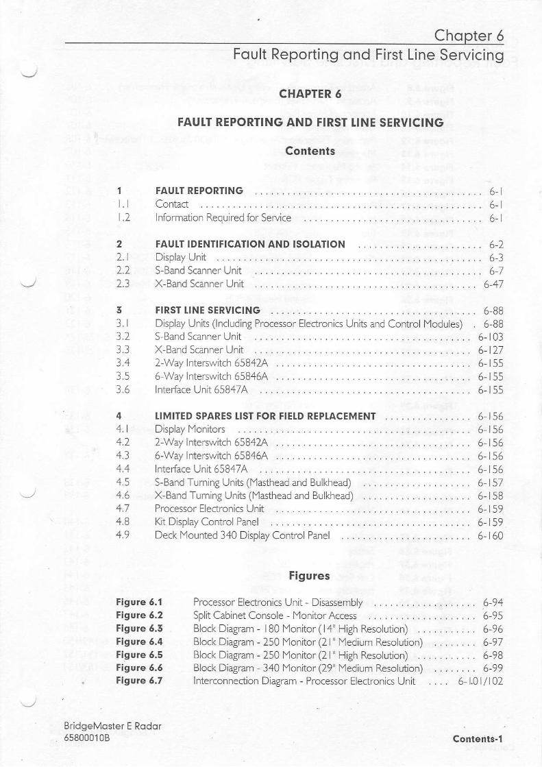
Figure 6.1Figure 6.2Figure 6.3Figure 6.4Figure 6.5Figure 6.6Figure 6.7
lnterface Unit 65847AS-Band Turning Units (lYasthead and Buikhead)X-Band Turning Units (lYasthead and Bulkhead)Processor Electronics UnitKit Display Control PanelDeck Mounted 340 Display Control Panel
Figures
Processor Electronics Unit - DisassemblySplit Cabinet Console MonitorAccessBlock Diagram - lB0 Monitor (14" High Resoluion)Block Diagram - 250 f4onitor (2l" Medium Resoh.rtion)Block Diagram - 250 Monitor (2l" High Resolution)Block Diagram 340 l'4onitor (29" lYedium Resolution)Interconnection Diagram - Processor Electronics Unit
6-946-955-966-976-98
BridgeMoster E Rodor658000108 Contents-1
Chopter 5Foult Reporting ond
Figule 6.8Figure 6,9Figure 6.10Figure 6.I lFigore 5.12Figule 6.15Fi9ule 6.14Fi9ule 6.15Fi9ule 6.16Figore 6,17Figure 6. '18Figure 6.19Figure 6.20Figure 6.21Figwe 5.21Figwe 6.22Figure 6'25Figwe 6.24Figure 6.25Figlute 6.25Figwe 5,27
Figure 6.28
Figure 6.29
Figure 6,30Figure 6.51
Figure 6.52
Figule 6.53Figure 6,34
Figure 6.55Figure 6.56Figute 5.47Figure 6.58Figure 6,59Figure 5,40Figure 6.41Figu.e 6.42Figule 6.45Figure 6.44Figure 6.45
First Line Servicing
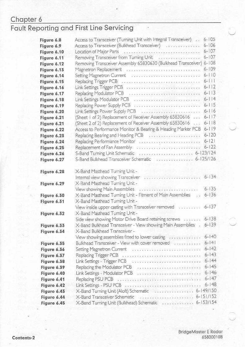
Access to Transceiver (Turning Unit with Integral Transceiver) . . 6 105Access to Transcelver (Bulkhead Transceiver) .... 6 06Location of lYajor Pads . . . . . . . . . . . 6-107qenoJ-g l r "ncce iver ' ' on T . |n i 'g Un i l . . . . .
" 107
Removlng Transceiver ,&sembly 65830630 (BuLkhead Transceiver) 6 | 0Bl Y a g n e t r o n R e p l a c e m e n t . . . . . . . . . . 6 1 0 9Set t ing Magnet ron Cur ren t . . . . . . . . 6 l0Replacing Tdgger PCB . . . . . . . . . . . . 6 l l lL i n k S e t t i n g s T r i g g e r P C B . . . . . . . . . . 6 1 2R e p l a c i n g Y o d u l a t o r P C B . . . . . . . 6 - l 1 3L ink Set t ings l4odu la to r PCB . . . . . . . 6 -114R - p a ( i - g D o v ^ e r S u p p l T P C B . . . . . . . o l 1 5L ink Set t ings Power Supp ly PCB . . . .6 - l16(Sheet I of 2) Replacement of Receiver Assembly 658306 6 . . . 6- l7(Sheet 2 of2) Replacement of Receiver Assembly 65830616 . . . 6 lBAccess to Performance lYonitor & Bearing & Heading lYarker PCB 5- I 1 9R e p l a c i n g B e a r i n g a n d H e a d i n g P C B . . . . . . . . . . . 6 - l ) 0Replacing Performance lYonltor . . . 5- l2lReplacement of Fan Assembly .. .. 6-122S - B a n d T r r n i ' g J n i r S c h e r o . c . . . . . . . . . . . . a 2 3 / 1 2 45 Band Bulkhead Transceiver Schematic ..... 6 25/126
X-Band lYasthead Turning Unit -l n t e r n a l v l e w s h o w l n g T r a n s c e i v e r . . . . . . . . . . . . . 6 1 3 4X-Band Masthead Turn ng UnitView showing lYain Assen'rblies . 6 135X Band f'lasthead Turning Unit - Fitment of Main Assemblies . . 6 136X-Band Masthead Turning Unit -
View lnsde upper casting with Transceiver removed .. ....... 6- 37X-Band lYasthead Turning UnitSide view showing lYotor Drive Board retainlng scTews ....... 5 L3BX-Band Bulkhead Transceiver - View showing Main Assemblies 6- 139X Band Bulkhead Transceiver -Vew showing assembl ies f i t ted to lower cas t ing . . . . . . . . . . . . . 6 -140Bulkhead Transce iver -Vewwi th cover removed . . . . . . . . . . . 6 -14 lSetting flagnetron Current .... . . 6-142R e p l a < n g r i g g e r P C B . . . . . . . . . . . . 6 4 1L i n f S e t t i n g s l r i g g e ' P c B . . . . . . . . 6 - 4 aReplacing the l ' lodulator PCB ... . 6-145Link Settings lYodulator PCB . . 6146R e p l a c i n g P S U P C B . . , . . . . . . 6 - 1 4 7Link Settings - PSU PCB . . . . . . . . . 6-148X-Band Turning Unit (Aloft) Schematic . 6-149/ 5AX-Band Transceiver Schematic . .6l5l/152X-Band Turning Unit (Bulkhead) Schematic .6-153/154
BridgeMoster E Rodor658000'l0BContents-2

Chopter 5Foult Reporting ond First Line Servicing
1 Foult ReportingFault diagnosis to component level is not possible withoutthe use of specialised testequipment.
The majority ofthe PCBs are assembled using sudace mount techniques.
Seruice repair is therefore by module (PCB) replacement only.
The module may be covered bythe Service Exchange scheme.
1.1 Contqct
. lf a unit exh ibits a fault, please contact your supplie r or local dealer, or if on I nte rnationalJ
lTaCe, Comacll
Litton Marine Systems B.V. Telephone: +(44) (0)20 8329 2400SERVICE CONTROL Or +(44) (0)20 8329 2000Burlington HouseI lB Burlington Road Fax: +(44) (0)20 8329 2458New lYaldenSurrey fi3 4NR Telex: 261545 MCDECCA GEngland.
For general non-urgent enquiries, the following e-mai addresses are also available:
[email protected] & [email protected]
It is recommended that any e-mails are sent to both ofthe above addresses.
1.2 Informqtion Required for Service
Please give the following details when reporting afaultl
. l. Name ofvessel (Satcom or Fax number iffitted).
2. Equipmenttype, including prefix and suffx letters.
3. Software status (version number).
4. Next port ofcall, ETA and ship's agents.
5. Fault description (with as much detail as possible).
b, Lontan nane,_/
BridgeM!ster E Rodor658000108 6.1

Chopter 6Foult Finding ond First Line Servicing
2 Foult ldentificotion ond lsolEtion
Refer to the following associated manuals for assistance in identiling and isolating Systemfaults.
6560l0l2 Bridgel'laster 1l S Band Supplement (Hybrid Synems) - Chapter 6Additionally coven DCU and Scanner Control Unitfaults.
6560l0l3 Bridgef4aster ll X-Band Supplement (Hybrid Systems) Chapter 6Additionally covers DCU faulls.
658000 L I Ship's Technical l'4anual(Additional information for S-Band and X-Band Systems)
658000 12 Ancillary Units and Radar Systems lYanual \-/
Covers DCU, TCU, 2- & 5 way Interswitch, Interface Unit.
BridgeMoster E Rodor6580001086.2 .

Disploy Unit Chopter 5Foult Reporting ond First Line Servicing
2.1 Disploy Uni t
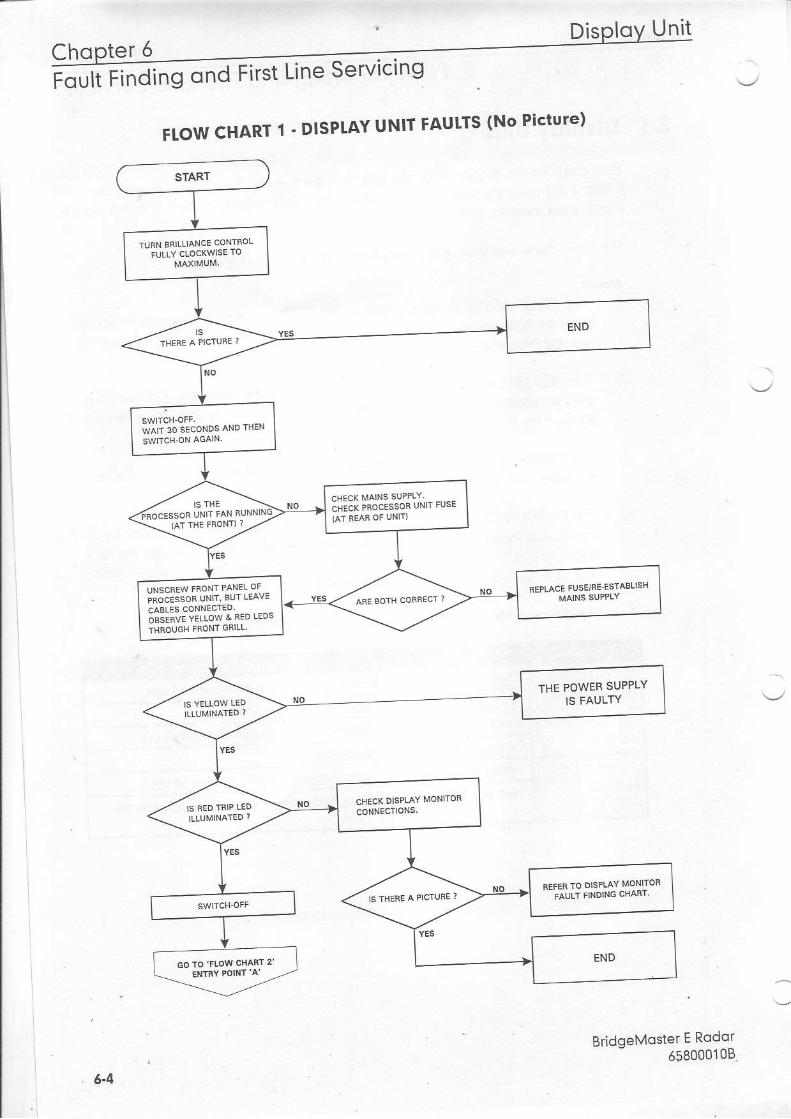
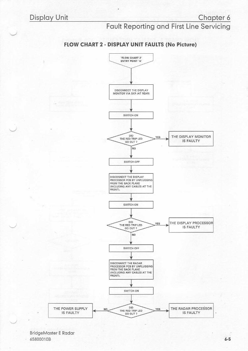
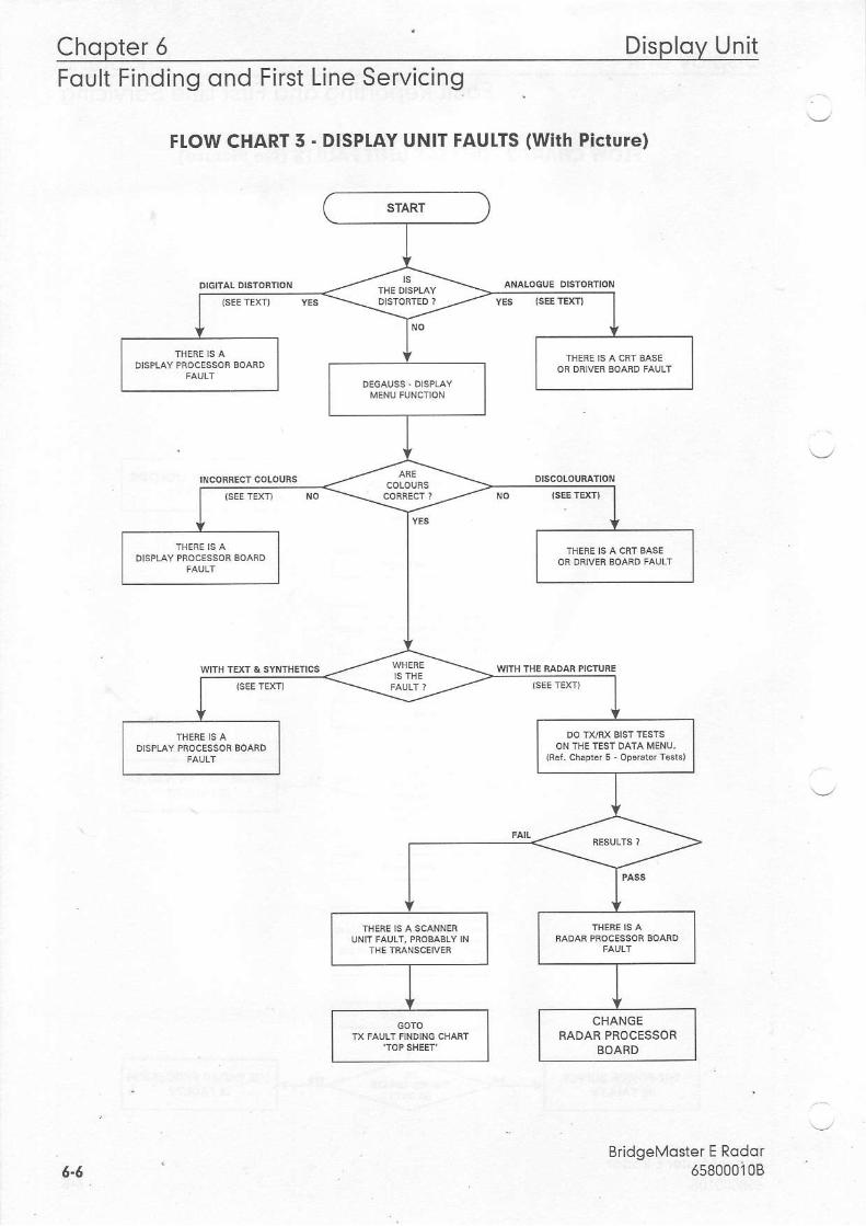
F ow charls forthe isolaton of Display Unit faults are given on the folowing pages. FlowChads | & 2 coverthe situation where there is no picture, and Flow Chart 3, where there s: ni.i rF h t thFrF ,r. ^thFr {:, lr<
The Fow Charts shou d be read in conjunction with the fo lowing notes.
Notet/ . The YELLOW LED, tndicanng power supply acbve, is located approximate, / AA mm
from the right hand stde ofthe power supply, towards the rear ofthe PSU. lt can beviewed through the front gill ofthe PSU.
5.
4.
The RED LED, indicating power supp/y tnp, is /ocated approximate, / 25 mm fromthe nght hand side ofthe power supply, t2wards the rear ofthe PSU. lt can be viewedthrough the front gri/l ofthe PSU.
T te DISPLAI Frl- SlJPoL\ nes a trermat u.:p :.,11 . fala^ ng t.e rena,a'a anover/aad, tt se/fresets a/1er /5 seconds.
The DlSPUY PaWER SUPPLY has a thermaltnp that shuts down the power supply ifthe heatsink temperature exceeds / /4"C. This thermal trlp will not activate the PSURED TR/P LED. The YELLOW LED b sinilar, not alfeded. The PSU wi/l self resetwhen the heatsink caab ta approximatel/ 904C.
Use the fo//awrng table to heb with decbions an DISPUY FLOW CHART 3.
BridgeMqster E Rodor658000108 6.5
Cho ter 6FoultFinding ond Line Servicing
Dis lov Unit
BridqeMoster E Rodor658000108
FLOW CHART 1 ' DISPIAY UNIT fAULIS (No Piqrure)
3tE3[Lilt?,iilf;fi'',"'
THE POWER SUPPLYIS FAULTY
":11,1i,:1,"J'HJXII:"
Disploy Unit Chopter 6Foult Reporting ond First Line Servicing
FIOW CHART 2 - DISPIAY UNIT FAUITS (No Picrure)
BridgeMqsler E Rodor6s8000108
MONT'OR VIA SI(i (AT REAR)
THE DISPLAY MONITOR
IINCLUDING ANY CA8IIS AT THE
DISPLAY PROCESSO
IINCLUDING NY CABLES AT flE
THE POWEF SUPPLYtS FAULTY
THE RADAR PROCESSOR
6.5
Chopter 6 Disploy UnitFoult Finding qnd First Line Servicing
Fl.ow CHART 5 - DISPIAY UNIT FAUITS (With Picture)
BridgeMosler E Rodor65800010B5"6

S-Bqnd Sconner Unit Chopter 6Foult Reporting ond First Line Servicing
2.2 S-Bond Sconner Unit
2.2.1 Technicol DescriptionThere are two basic types ofS-Band Scanner Uniti
The separate Transceiver is designed to be
. bolts, studs or screws (coachbolt5).
BridgeMoster E Rodor558000108
with an integral transceiver modulewithout an integral tmnsceiver
Each type can have a number ofvariants dependent on motor supply and the options thatare itted.
The Scanner Unit comprises an Antenna, an antenna suppoft casting, and a Turning Unit.
Included in the Turning Unit is a motor and gearbox, a Bearing and Heading lYarker pcb, anInput pcb, and optionally a Pedormance lYonitor and rntegral transceiver module.
The Transceiver Unit comprises, a base casting , cover, transceiver module and Input pcb.
Communicaton between the Transceiver and the Display is by means ofa serial data link.Where a separate Transceiver Unit is used, an RF feeder (coaxial) is used to transfer themicrowave energ/ befl&een the Transceiver Unit and the Turning Unit.
The Scanner Unit and the Transceiver Unlt are compatible with BridgeMaster display units ifa Display Compatibility Unit is used.
Physicql ArrqngementsThe Tuming Unit is constructed from a central aluminium cading, to one side of which rsattached a motor and gearbox. The tenninal strips for interconnecting cables to other unitsare under a coveT on the opposite side to the motor and gearbox.
At either end ofthe Turning Unitthere is an aluminium cover. The pedormance monitor ishoused underthe front cover and, when fitted, the Transceiver Unit is housed undertherear cover. lf no transceiver module is i11ed, a shallower cover is used. The transceivermodule can be removed for below deck servicing,
Four 14l5 bolts are used to attach the Scanner Unitto the radar platform orwheelhouseroof. The Antenna is attached to the Turning Unit bythe antenna suppoft casting, an RFfeeder cab e is used to transferthe microwave signals belveen the Turning Unit and theAntenna.
lnterconnections bebdeen the Scanner Unit and other units in the system are made usingscreened cables. Allthe cables that enterthe Scanner Unit do so via waterproof cable glandsthat incorporate an EIYC gasket that makes contacl with the cable braid.
Bulkhead mounted and is atbched usingfour M8
6-7

Chopter 6 S-Bond Sconner UnitFoult Finding ond First Line Servicing
TRANSCEIVER MODULE OVERVIEW (S-Bond)
The transceiver module can be fitted in the Turning Unit, or mounted on a casting for belowdeck bulkhead mounting as a separate unit. The module incorporates the Modulator pcb, aPower Supply pcb, Trigger pcb, the Receiver, and the microwave components.
Communication between the Transceiver Unit and the Display Unit is by means oftwoserial data link, one from the Transceiverto the Display Unit, and one from the Display Unitto the Transceiver.
This information is transmitted using a special data cable that incorporates four twisted pairs.Two pairs are used for data transmission, one pair is used for trigger, and the other parr 6spare.
The data passed from the Transceiver to the Display includes;
. Heading Yarler
. Incremental Bearing
. Transceiver Stai.ts
. Error Messages
. Built In Test Equipment (BITE) data
. Tuning Indicator
The data transmitted from the Displayto the Transceiver includes:
. Stand byllransmit
. Pulse Length
. Tuning
. AFC/Manual' Seclor Blankng. Performance lYonitor Control, and Installation Settings.
Power SupplyThe power supply operates from the ship's AC mains, and provides all ofthe powerrequirements forthe electronic modules within the Turning Unit and Transceiver. The ACmains is always present atthe power supply even when the radar is switched ofatthedisplay.
The presence of data on the serial data link when the display is switched on is detected bythe power supply, which then becomes active. The power supply includes a Power FactorCorrection circuit, and a number of switching regulators to generate the necessary voltagesupplies. Overcirrrent detection circuits protect the power supply against overloads on itsourpuls.
BridgeMostef E Rodor6s80001086-8

S-Bond Sconner Unit Chopter 5Foult Reporting ond First Line Servicing
Trigger PCBThe Trigger PCB processes the serial data from the Dispay Unit, and generates the requiredcontrol signals forthe Transceiver. lt monitors functions within the Transceiver, the HeadingMarker, and encodes the information fortransmission to the Display Unit. The data stransmitted each time a bearing pulse is received from the Turning Unit. The various timingsignals required by the transceiver includingthe pulse repetltlon frequency (prf), areoenchtcd hv thF #ooF. ..h
Modulqtor PCBThe modulator pcb generates the high voltage negative pulses required to drive thernagnetron. The modulator pulse widths and timing srgnals are controlled from the triggerpcb. A spark gap on the modulator is fired lfthe magnetron fails to operate. Continualoperation ofthe spark gap is detected and signal is fed back to the trigger pcb. When thetrigger pcb detects this signal it switches the radar to standby, and generates an error signaltobe transmitted to the Dispay Unit viathe serial data link. The error signal causes the DisplayUnitto swltch to standby and generate an error aarm.
Microwove CircuitThe transceiver employs a conventional three poft circulator to direct the path ofthemicrowave energy to and from the antenna. A magnetron coupled to the circulator providesthe RF energy to be transmitted. A solid state limiter coupled to the circu ator protects thereceiver from high powered microwave signals from the magnetron, or adjacent radars. Asignal from the trigger pcb is used to enable swept attenuation to be applled to the solid statelimiterto reduce the system sensitiviry at shoft ranges.
ReceiverThe receiver consists ofa low noise ampliller, a mlxer, a linear preamplifier, a logarithmjcampiifier, and a video amplifier. The 60MHz output ofthe mixer is amplified by the linearpreamplifier fo lowed by a logarithmic amplifier, the outpLrt of which is detected, the res!ltingvideo signal is then fufther amplilled before transmission to the Display Compatiblllty Unit.
The receiver also incorporates an AFC system. Once the receiver has been tuned, the AFCsystern ensures thatthe receiver remains on tune during variations in tuning due to thermaldrift ofthe mixer and magnetron etc,
The operator can select between manualtuning and automatic tuning. A signalfrom thetrigger pcb ls Lrsed to selectthe .node ofoperation. A signalfrom the AFC circuit is fed to thetrigger circuitto indicate the state oftune ofthe receiver. This signal is at its minimum valuewhen the receiver is correctly tuned.
BridgeMqster E Rodor658000'108 6.9

Chopter 6 S-Bond Sconner UnitFoult Finding ond First Line Servicing
AUTOMATIC START-UP SEQUENCE (S-Bdnd)The automatic staft-up sequence described below, should be read in conjunction with.gu-" 6.22 'S-B"-d Trrnirg U' . ScheratL .
Stort-upImportdnt NoIice Ance mans ts appled to the PSU board the Power Factor Correctton(PFC) circuitry skrts and generates 39AV lt shauld be noted that whi/st mains is app/ied thePFC is a.tive and cannot be manua/ly switched ofr The staft ctrcuitry an// cantro/s the /1/backconvefter so High Vo/tage DC is present on pnmary power camponents whenever mans 6present on the boad. Thls ldcl shoald be noled when servicing the frdnsceiver.
The Power Supply in the Transceiver is only active during normal operation when there is aDisplay (or CompatibiLity Unt) connected to t. The RS422 serial data stream from theDisplay is used to drive an opto-coupler in the PSU which detects the presence of eitherpoariry voltage and enables the flyback converler in the PSU.
The RS422 serial data stream from the Disolav enters the Inout Board on connectorTSB , 2 as "DU DATA+ and DU DATA_'. t is then passed to the Trigger Board via PLYBI 5, | 7, and then on to the PSU via PLTI I | , | 2 ( as PSU START and PSU START RTN ).For tes'r purposes the PSU can be turned on in the absence ofa serial data stream by ljnkingpins 2 on LKA (PSU).
Tronsmit EnqbleWhen the operator selects Transmit, the TU Enable signa is act vated LOW on the TriggerPCB ( PLYH 1 0). On the S-Band Scanner Unit, this signal is fed vla the Power Supply Unit tothe Input PCB and (via TSB 0) to the Scanner ControlUnitto start the antenna rotating.Once the antenna has done one complete revolution transmission is started. When standbyls selected, transmission is immediately halted and, aller one complete revolution oftheantenna, TU Enable is disabled.
The lYodulator starts to generate radar pulses when the Trigger PCB sends it MODTR GGER pulses (to PLVC 9). Note that the CHARGE TRIGGER puLses (on PLVC B) arepresent even in Standby mode.
A signal indicating that the lYagnetron has ired is fed via MAG SAMPLE from PLVC 7 on thelYodulator PCB to the Trigger PCB. This signal is processed on the Trigger PCB andoutputted as TXTRIG (PLYB 20 & 2l) to the Input PCB (PZB 20 & 2l) and then to theDisplay Unit vla TSB 5 & 6.
Note - TX DATA is sent from the Transceiver to the Diso/av UnitDU DATA is sent from the DisDlay Unt ta the Tnnsceiver Unt
The Trgger PCB processes the serial data lnputfrom the display, and generates the requiredcontrol signals forthe Transceiver.The data is transmitted each time a bearing pulse isreceived from the Turning Unit. The various timing signals required by the Transceiverincluding the Pulse Repetition Frequenry (PRF), are generated by the Trigger pcb.
Bridgelvoster E Rodor6580001086 .10

S-Bond Sconner Unit Chopter 6Foult Reporting ond First Line Servicing
Mdgnetron OpelotionThe high voltage negative pulses required to drive the magnetron are generated by thelYodulator PCB. The modulator pulse widths and timlng signals are controlled from theTrigger pcb. A spark gap on the lYodulalor is llred ifthe magnetron fails to operate.Continual opemtion ofthe spark gap is detected and a signal is fed back to the Trigger pcb.
On detedion ofthis signal, the Trigger PCB switches the radar to Standby, and geneEtes anerror signal which is transmltted to the Display Unit viat|e serial data link. The error signalcauses the Display Unitto switch to Standby and generate an error alarm.
When Standby is selected, rotation ofthe Antenna is inhibited. Unless in Test lYode,transmission from the radar is inhibited if the Antenna is not rotating.
On the Trigger PCB, there is atimer circuit which is basically a capacitor that slodydischarges (between 4s and I 8s) when power is removed from the PCB. On power-up themicrocontroller measures the charge remaining on the capacitor to determine whetherthetransceiver has been switched offor long enough to warrant inhibiting transmit for th reeminutes until the magnetron heaters have had time to warm up again.
The other analogue signals into the Trigger PCB come from the Modulator. The Moduiatorsupply voltage and the magnetron current (only when transmitting) are measured and sent tothe Display as an aid to fauhfinding. The spark gap detect signal is generated bythemodulator when the magnetron arcs over, if it reaches a predetermined levelthemicrocontroller inhibits tmnsmission for approximately one second and sends an errormessage to the Display.
BridgeMoster E Rodor658000108 6.11

Chopter 5 S-Bond Sconner Uni tFoult Finding qnd First Line Servicing
TURNING UNIT OVERVIEW (S-Bond)
Drive SystemThe scanner motor is an AC induction motor. lt drives either a l2t I or a 20: reductiongearbox. The oLtput ofthe gearbox drives the linal output helical gear via a pinion to give anovemll reduction between the motor and Antenna of approximately either 30: or 60: Idep-nda'T on whFthe'rLe Tu" ng Uni s a "i8r speed !a a"r o -o..
The scanner motor is connected to the ship's AC Supply by a Scanner Control Unit. Thisunit incorporates a contactor contro led by the Transceiverto switch tlre scanneT motor on.
When standby is se ec|ed, rotation ofthe Antenna is inhibited. Unless in test mode,transmission from the radar s inhiblted if the Antenna is not rotating. An isolating swit.h isprovlded for AC systems to switch the scanner motor supply of for safe servicing
Bedring ond Heading Morker SyslemA disc with 28 teeth is atlached to the Antenna torque tube and combined with an opto-coup er generates l28 pulses per rotation ofthe Antenna.
A second opto-coup er together with a flag on the toothed disc generates a Heading Markerapproximately J0' before the Antenna is pointing dead ahead. Correct alignment oftheHeading Ylarker is set at installation by electronic adjustment within the Display Unit.
Both opto-couplers are on the Pulse Bearing PCB. The Pulse Bearing PCB mutip ies the 128bearlng pu ses by 32 to generate 4096 pulses perAntenna revolution. The 4096 azirnuthpulses and the heading marker are routed through the lnput PCB to the Trigger PCB wherethey are incorporated into the serial data to be transmitted to the Display Unit.
Where it is not possible to adjustthe Heading marker alignment at the dispLay, optional ex.tracircultry can be fitled to the Input pcb to allow the alignment to be made electronically withinthe Turning Unit. When this optlon ls fitred an additional ( iso ated ) Heading lYarker outputis p rov ded . ,& an option for special applications a size I I synch ro can be ftted as aralternative source of bearing information.
InlerconneclionsAC power to the motor is by direct connection to terminal strips in the termlnal boxatlached to the motor. The terminations for interconnections for the transceiver and theTurning Unit are under a cover on the side ofthe Turning Unit. The AC power from theisolatlng switch ls terminated at aterminal block within the filter box. All other connectionsare made to pJugs or removable terminal strips on the input pcb.
BridgeMoster E Rodor6580001086.12'

S-Bond Scqnner Unit Chopter 5Foult Reporting ond First Line Servicing
TRISGER PCB (S- Bond)
Generol DescriptionThe Trigger PCB controls the operation of the Tmnsceiver under instruction from theDisplay. There are two serial link, which are used to transfer control messages from theDisplayto the Trigger PCB and Transceiver information back to the Display. The TriggerPCB generates the controi and tuning signals required by the lYodulator, Receiver,Pedormance lYonitor and Biased Limiter. The PSU is enabled with a signal from the TriggerPCB.
Signols To /From the Trigger PCBTo/From Display
Serial Data to DisplavSerial Data from DisplayTriggerto Display
TolFrom lYodulatorP, , l cF I FnoJh <F iF . r l i .F (
Charge and lYodulator TriggerslYagnetron Heater Turndown signal ( only used for S Band, Long Pulse operation )Voltage/Current Monitor signalsl025kW and 5 /X Band Configuration signals
To/From ReceiverTuning Voltage signalBandwidth Control signalAFC/Manual controlAFC TriggerTune Indicator signal
To Biased LimiterTrigger signal
To Pedormance MonitorOn/Of signallYode Control signalTuning Voltage signals
-o,f rom Power SJpply DCB
+30V, + l2V, +5V, 0V & - l2V Supply linesTurning Unit EnablePower Supply Stad and Retum
BridgeMoster E Rodor65800010B 6 .12

Chopter 5 S-Bond Sconner UnitFoult Finding ond First Line ServicinE
FUNCTIONAT DESCRIPTION (S-Bqnd Trigger PcB)
The B0C5 family microcontroller provides overall control ofthe Trigger PCB functions.Program memory and RAIY are included withln the microcontroller lC. Serial l/O is handledbythe microcontro lers internal UART and an e>ternal RS422A driver and receiver. Baudrate is llxed at76800 baud for operational use but is link selectable to 9200 or 38400 baudfor test purposes. The sedal data format is B bit data, I stop bit and even pariry.
The Display sends serial messages comprising four or llve characters depending on messagecontent. Control messages are four bltes ong and tuning messages are llve. The tun ngvotage levels are sent as l2-bit values which are converted on the Trigger PCB using afour-channel DAC before ampliication,ibufering and distribution to the Receiver and PerformanceMonitor.
The Bearing signal from the Turning Unit is used to initiate serial transmission from theTrigger PCB such that each time one ofthe 4095 azimuth pulses per rev is generated andfed into one ofthe microcontrollers lnterrupt pins, a character (one b)4e) is sent to theDisp ay. One bit in each ofthe characters sent is dedicated to the heading marker, on everynew heading marker pulse from the Turning Unit, the bit ls toggled.
The Power Supply in the Transceiver is only active during normal operation when there ls aDisplay (or Compatibility Unit) connected to it. The RS422 serial inputfrom the Display isused to drlve an opto isolator which detects the presence ofeither polarity voltage andenables the PSU.
Trigger OuputsThere are a numbeT oftrigger signals generated by the Trigger PCB:
Pre-TriggerCharge TriggerYodu ator TriggerDisplay TriggerPerforroance l'4onitor TrlggerAFC TriggerSwept Attenuation I nitiate
The Charge Trigger is the timing signal used to recharge the Modulator PFN This isgenerated by the microcontroller using an internaltimer routine setto the appropriate PRFforthe pulse length seleded. A wobbulation facor is added to the basic timingto ensure thatno bro €dar transmissions are locked together. The wobbulation is calculated according tothe number of serial messages received before going to transmit and the position oftheantenna between each trjgger pulse.
An optional Pre-trigger will be produced approxlmately I lps before the modulator trigger.This is not a normallyfitted option and is intended for use in Special Options applicatons.
BridgeMostef E Rodor5s80001086.14

S-Bond Sconner Uni t Chopter 5Foult Reporting ond First Line Servicing
The l'lodulator Trigger is used to let the charge out ofthe PFN into the magnetron and isthe triggerthat initiates the modulator firing. lt is delayed frorn the Charge Trigger by l00prsand gated offwhen the transceiver ls in standby.
ln standby, the Display and Per{ormance Monitor Triggers are generated from the lYodTrigger pulse. When the transceiver is in transrnit mode the triggers begin on the Jeadingedge ofthe magnetron sample pulse and end after a preset time, adjustable us ng R\ | .
The AFC Trigger s used by the receiver when in AFC mode and is only generated when thetransceiver is in transmit mode. The pulse is (arted on the front edge ofthe lYodulatorTrigger and terminates on the back edge ofthe magnetron sample pulse.
The Swept Attenuatlon lnitiate pulse is the timing signal fed to the Limiter Drive PCB whichgenerates the contro forthe biased limiter. lt is initiated bythe front edge ofthe Pre-trigger(approximate y 2ps priorto magnetron firing) and terminated 2.57-rs afterthe leading edge ofthe magnetron samp e pulse.
The Display and PM Triggers are essentialy the sarne trgger and are present at all timeswhen the radar is powered up. They are nitiated bythe lYodulator Pulse and last forapproximate y 2.5ts.
Anqlogue OutputsThe Trigger PCB generates fourtuning signals; LO.Tune, PIY Tune, XrAdjust and Xt Adjun.These signals are coded as l2-bit digital values and incorporated into the serial messagesfrom the D splay. A l2 bit, four channel DAC is used to generate the tuning signals from themessage data. Additional bufering is added to the LO and PIY Tune outputs ofthe DAC andx3.5 amplilication to the Xr and Xt Adjlst signals.
LO Tune is the 0V to +5V receivertuning control and PM Tune the 0V to +5VPefformance Monitor main tuning control. Xr and Xt Adjust are ovto + l5V signals used tocontrolthe recelve and transmit attenuators in the Pedormance lYonitor.
Anologue InputsThere are various analogue inputs to the Trigger PCB from other PCBS in the transceiverand some on board signals that are fed into an eight channel 8-bitADC, and converted todigitalvalues either for further processing by the rnicrocontro ler orto be passed to theDispiay viathe serial message link.
The signals on the Trigger PCB that are measured are the dropouttimer and a l2V and+30V supp ies. The timer circuit is basically a capacjtor that slody discharges (between 4sand | 8s) when power is removed from the PCB. On power-up the microcontrollermeasures the charge remaining on the capacltorto determine whetherthe transceiver hasbeen switched offfor long enough to warrant inhib'Ltlng transmlt for three minutes untilthemagnetron heaters have had time to warm up again. The power supply levels are measuredand the results sent to the Display as an aid to fault diagnosis.
BridgeMoster E Rodor65800010B 6-1s

Chopter 6 S-Bond Sconner UnitFoult Finding ond First Line Servicing
One channel ofthe ADC is used to detect whether a Performance lYonitor has been fittedto the system. The voltage on this channel wll be lower than a preset value if a PerformancelYonitor is present otherwise it wi I be pulled to the +5V supply rail. This information isencoded and sent as part ofthe configuration message to the Display.
The Receiver sends a tune indicator signal to the Trgger PCB which indicates how close it isto being on tune. This signal is coded as paft ofthe serlal message and sent to the Display.
The other analogue signals into the Trigger PCB come from the Modulator. The Modulatorsupply voltage and the magnetron current (only when transmitting) are measured and senttothe Display as an aid to falltfinding. The spark gap detect signal is generated by themodulator when the nragnetron arcs over, if it reaches a predetermined level themicrocontroller inhibfu transm ssion for approximately one second and sends an errorrnessage to the Display.
Digitdl OutpulsThe digital outputs from the Trigger PCB are all straight forward on/ofcontrol signals to\ / r r ^ ' . n r *c ^ f+h . + r ,nc .F i \ ,F r
Signas to the Recelver seled wide or narrow bandwidth (Wideband) and AFC or manualtuning mode (AFC On). Narrowband is selected when the modulator is transmitting in longpulse and briefly during pulse length changing. AFC or manual mode is selected bythe radaroperator and is part ofthe control message sent from the Display.
l'aodulator signals IYP and SP are used to set the pulse length as requested by the radaroperator, SP set to 0V indicates short pulse operation, Y1P setto 0V indicates medium pulseoperation and both SP and ['1P set to +5V indicates long pulse operation. SP and MP bothsetto 0V is an illegal state and will not happen in normal operation. Tumdown enable rs usedto reduce the heater current in the magnetron and is only set when an S-Band magnetron islltted and is transmitting in long pulse.
The control signals Pfl On/Offand PM Tx,41x are used to swltch the Performance lvlonioron and to switch it between system test mode and receiver test mode.
TU Enable is the control signal fed to the Motor Drive PCB to initiate rotation oftheantenna. When the operator selects transmitthe TU Enable signal is activated to start theantenna rotating.
Once the antenna has done one complete revolution transmission is started. When standbyis selected, transmission is immediately halted and, after one complete revolLrtion oftheantenna, TU Enable is disabled.
Optionol UOThere are several optional l/O signals for use with Special Options variants ofthe PCB| Pre-trlgger (as described in t|e section on triggers), Bfrernal Trigger Input and Radar Inhiblt. TheExternal Trigger inpLr1 is used when the modulator needs to be triggered from an externalsource ratherthan the Trigger PCB. Trigger signals fed.Jo this input are pd limited to prevent
BridgeMoster E Rodor6580001085-15

S-BondSconner Unit
BridgeMosier E Rodor
658000108
Chopter 6
Foult RePorting ond Line Servicing
II1-
damase ro the modurato': Fg"l l1iil'l'^:,:""'T: ::l* |]j'15 :nffi :i":,f ::$J;[t'*:i:i:i,:i,5 ::Tffilil",ff ::' ffi';";J'r*c;' p"i'"" ;*'** of the internar pr{s'
il:'::t :.'"di"i,$liirt:lm :i::l];*,:r:m:,iil"i**iT ;:"*' *"?"'lJ:::::[:i"'H ;:U:.:niifi ;::.i']i,pr"v'""""e* r": :ll:11..'"* "*'i,r"ii,.,, i "i*",.n",* ;l1xi:9lii,liffi
"**'*:1; l.::::;1'ft*i':''-T,Il'l^1':m#;,ff ',:1ll:.'*3:::Iffi
ff :X..ffi #"*y;Jl.:,:g:;:f;1,"by the microcontroller are the power sul
seclon on analogue InPUts
T::"T:*:',* .:*, p: I's--J,fi :::i".lTi;,f,:ffi:i:1il'f;*; T;t ;iY."tou ;nr. prod.r.tion resring or ne PCB a'd rs In-]li"
:l ll il:.:-'^:::^.-,,*. .. "::-':;:mm*Lm ::n*'JH;: ::::#:i':'":*" ^"
ft ::rff J:r;"f ,1iii1'*:i:Tfihuf ,i;H:?:ki,rl:+Tffi ";":l:.ill ;:il:"lll i]'lir"t"1ffi;; uJ'onnir"a'o tu'" qr-oulPuT sia'e the
f "l':::=i'i:::xH:t',;:l*:J:;R:il',:;11::''J5,8$t-':;{?H':;"::il:;;';;:; 'e' (i 'curry o' rhe rngge PCB
' 6.17

Chopter 6 S-Bond Sconner UnitFoult Finding ond First Line Servicing
IRANSCEIVER POWER SUPPTY (S-Bond)
Generql IntormotionThe power supply js an AC to DC lnvefterthat generates the supplies for the Transceiver'The lnvefter is housed on a slngle board and is powered by an AC supPly of nominal | 5Vor 230V in the frequency -ange 4f-64H2.
The power unit uses a boost convefter front end to provide a regulated high voltage d c toa flyback converter providing the oL'tput supplies. Some ofthese supplies use addLtionalswitch mode .onvefters to provide regulated outpub.
The outputs supplied bythis power supply are:Vaiable 500V, +30V, +20V, magnetron heaters (viafudher regulator, + 2V, l2Vandt 5V) and for the X-Band Turning Unit variant, + 50V for the Motor Drive pcb
l'" po*er -^i ha< lhe followi^g eatu-es:
. -600V adjLrstable overthe range -550V to -650Vfor control of magnetroncurrent via modula|(Jr.
. OLrtput shoft circut Protection.
. Universal input from 95Vto 276V withouttap changing. Powerfactor correctedproviding a PF of better than 0.9.
To switch the flyback converter on the opto-coupler detects the presence of a serlai data'
stream frorn the display at PLTH I I , | 2. On detection of the data stream the phototransisto r withjn U5 is turned on puling down the gate of Q2 below its threshold vo tage.
Q2 turns off allowing the compensation pln 1 U4 to rise enabling output of the lC U4. In thePSU of state Q2 is held on by current in R37 from Vcc.
Fortest purposes the PSU can be tLirned on in the absence ofa serial data stream by linking| 2 on LKA.
Note that once the mains supply is applied to the PSU board, the PFC (Power FactorCorreclion) circuit starb and generates 390V. Whilst mains is applied, the PFC is aaive andcannot be manually switched off. The staft clrcuitry only controls the flyback convefter andso High Voltage DC is present on primary power components whenever mains is presenton the board. This loct should be noled when servicing lhe Trqnsceivel.
MODULATOR PCB (S-Bqnd)
Functionql DescriptlonThe princlpalfunction ofthe lYodulator PCB is to geneate an 8kV, BA negative pulse todrve the cathode ofthe magnetron. An SCR is used to resonantly charge a Pulse Forming
. Network (PFN)to - l200Vfromthe 500V lYodulator HT supply. The charging rycle isniii:ied bv ihe Chi ee TriFee.. The number ofsections ofthe PFN is selectable bythe
BridgeMoster E Rodqf5580001086 .18
S-Bond Sconner Unit Chopter 5Foult Reporting qnd First Line Servicing
relays controlled by the Pulse Length Control Lines. The number of sections ofthe PFNJsed de'ines the le-sth oftLe ouroLt o-,se
At a defined time afterthe PFN is fully charged it is discharged by three series conned|edlnsulated Gate Bipolar Transistors through a pulse transformer. The discharge is initiated bythe flodulator Trigger. The Pulse Transformer, which has step up ratio of l2t I , transformsthe resulting pulse to BkV. The back edges ofthe medium and short pulses are speeded upby a saturable reactor connected across the primary ofthe pulse transformer.
Other functions include regulating the magnetron heater supply, monitoring a spark gap toensure correct operation ofthe magnetron, and generation of atiming reference fortheRadar Trigger.
Inpuls to the Modulqtor PCB-600V Modulator HT Supply+20V l'4odulator Trigger Supply+ l6V - +27V lYagnetron Heater Bu k Supply+ l2v- r2v
Short Pulse Control LinelYedium Pulse Control LineCharge Trigger
lYodulator Trigger
Turn Down Enable
Oulputs trom the Modulotor PCBPrimary sample
Ylagnetron current sample
ry Active
u/hcn OV <clc.t< <h6'r n ,l<F
when 0V selects medium pulse.initiates charging of Pulse Forming Netrvork. TypicallylAmp current pulse.initiates discharge of Pulse Forming Nebr,,ork. Typically4us, 3.5V positive pulse.dc voltage controls the magnetron heater voltage. 0Von long pulse, 3.5V Standby l,ledium and Shoft Pulse
positive pulse sample from pulse transformer used toinitiate Radar Tdgger. Typically 40V amplitude.a dc voltage propoftionalto the magnetron currentderived from the secondary ofthe pulse transformer.Typically +2.5Va signalthat is normally ovthat rises to >2.5V if thespark gap operates continuously for 2 seconds. Thissignal is used by the Trigger PCB to indicate atEnsmitter fault to the display.sample of lYodulator HT Supplyfed to Trigger PCB forinclusion in BITE message sent to display.I i"l ,enings rsed to dell-e nodLrlator rype to I aggerPCB. 0V or 3.5V dependant on link settings.
HT Sense
TX Define
BridgeMbster E Rodor65800010B 5-19

S-Bond Sconner UnitCho ter 6Foul tFinding ond First Line Servicing
Mqgnelron Heoter SUPPIYThe magnetron heateE are derived from the Magnetron Heater Supply at PLVD I and
PLVD2. This supply may vary between l6Y aod 21Y
The Modulator PCB is conllgured for the intended magnetron by the setting oflink LKI fitred
to the lYodulator PCB. Refer to Figure 6 lI'Link Settings lYodulator PCB', in this chapter'
for fudher information.
WARNING - On no dccounl should the hedter volldge be meosured whilst the
frd nsc elver is trd n s mitrln g.
ln a | ol(N X-Band system, the magnetron requires a heater voltage (measured between
TSI I and TSJ2) of 5. lV on Standby, Short Pulse, Medium Pulse and Long Ptrlse
ln a 25KW X Band system, the magnetron requires a heater voltage (measured between
TSllandTSJ2)of6.lVonStandby,shortPulse,andMediumPulse On Long Pulse, this may
be turned down to 5.lV dePending on the rype of magnetron frtted'
In a 30KW S-Band system, the magnetron requires a heater voltage (measrrred between
TSJ L and TSl2) of 6. lV on Standby' Shoft Pulse, and lYedium Pulse On Long Pulse, this may
be turned down to 5 lV depending on the type of magnetron fitted
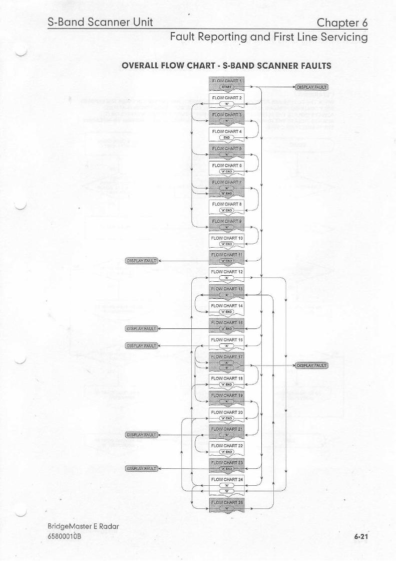
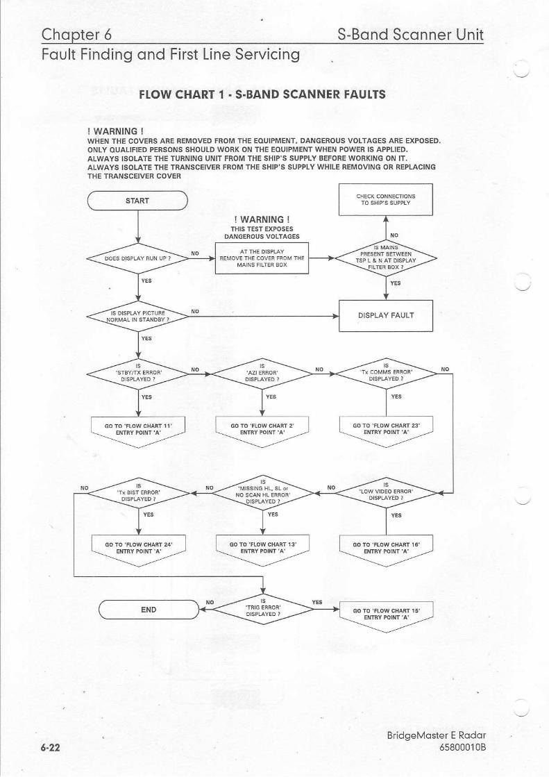
2.2.2 Fqull lsolotion Flow Chqrts (S-Bond Sconners)
Flow chafts for isolating faults on S Band Scanner Units are given on the following Pages'The lead sheet shows the overall flow through individual Flow Charts I to 25'
BridgeMoster E Rodor65800010B6-20
S-Bond Sconner Unit Chopter 6Foult Reporting ond First Line Servicing
OVERAI.T FI.OW CHART - S'BAND SCANNER FAUITS
BridgeMoster E Rodorrseooorbs 6.27
Chopter 6 S-Bond Sconner UnitFoult Findino ond First Line Servicino
FIOW CHART 1 - S.BAND SCANNER FAUI.TS
! WARNING !WHEN THE COVERS AFE REMOVED FROM IHE EOUIPMENT, DANGEROUS VOLTAGES ARE EXPOSED.ONLY OUALTFIED PERSONS SHOULD WORK ON THE EOUIPMENT WHEN POWER IS APPLIED.ALWAYS ISOLATE THE TURNING UNIT FROM THE SHIP'S SUPPIY BEFONEWORKING ON IT.ALWAYS ISOLATE THE TRANSCEIVER FROM THE SHIP'S SUPPTY WHILE REMOVING OR REPLACINGTHE TRANSCEIVER COVER
BridgeMoster E Rodor65800010B
. --".1"--_l
I WARNING !
DANGEROUS VOLTACES
--+Et ""1yt *i
---,-^'"---.-
=v ------*^:"". *-=-----.'.q] :-
L-=-,,"':..",,END
5-22
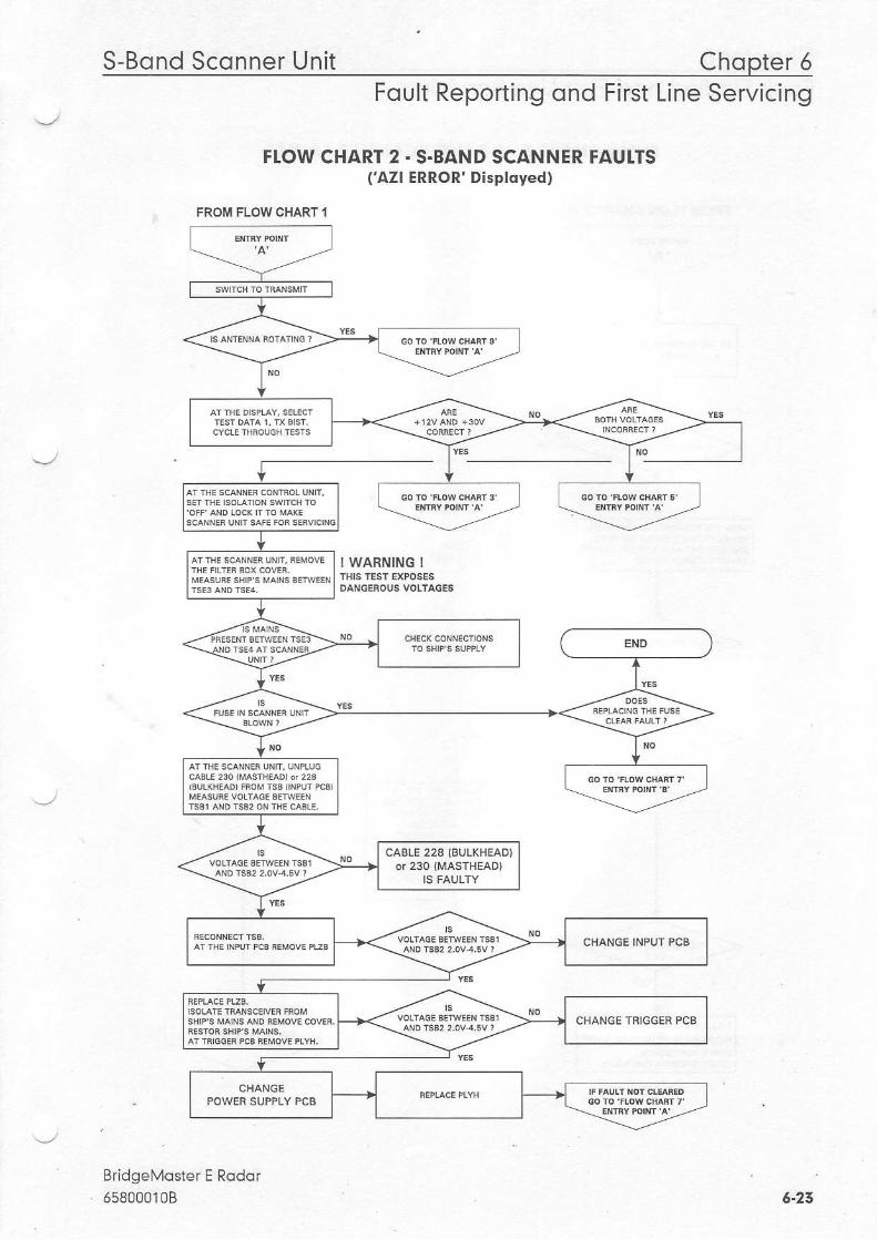
S-Bqnd Sconner Uni t Chopter 5Foult Reporting ond First Line Servicing
FI.OW CHART 2 . S.BAND SCANNER FAUI.TS( 'AZl ERROR' Disployed)
! WARNING !
BridgeMoster E Rodor658000108
FROM FLOW CHART I
CABLE 228 {BULKHEAD)
CHANGE TRIGGER PCB
5-23
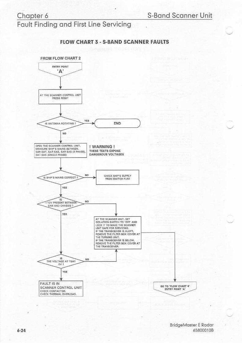
Chopter 5 S-Bond Sconner UnitFoult Finding ond First Line Servicing
FI.OW CHART 5 . S-BAND SCANNER FAUI.TS
! WARNING !THESE TES]S EXPOSEDAIIGEROUS VOLTAGES
BridgeMoster E Rodor5s8000108
FROM FLOW CHART 2
sAR-sAT' sAr-sAs, sA8 sAs 13 PHASE,,
FAULT IS INSCANNER CONTNOL UNIT
6.24
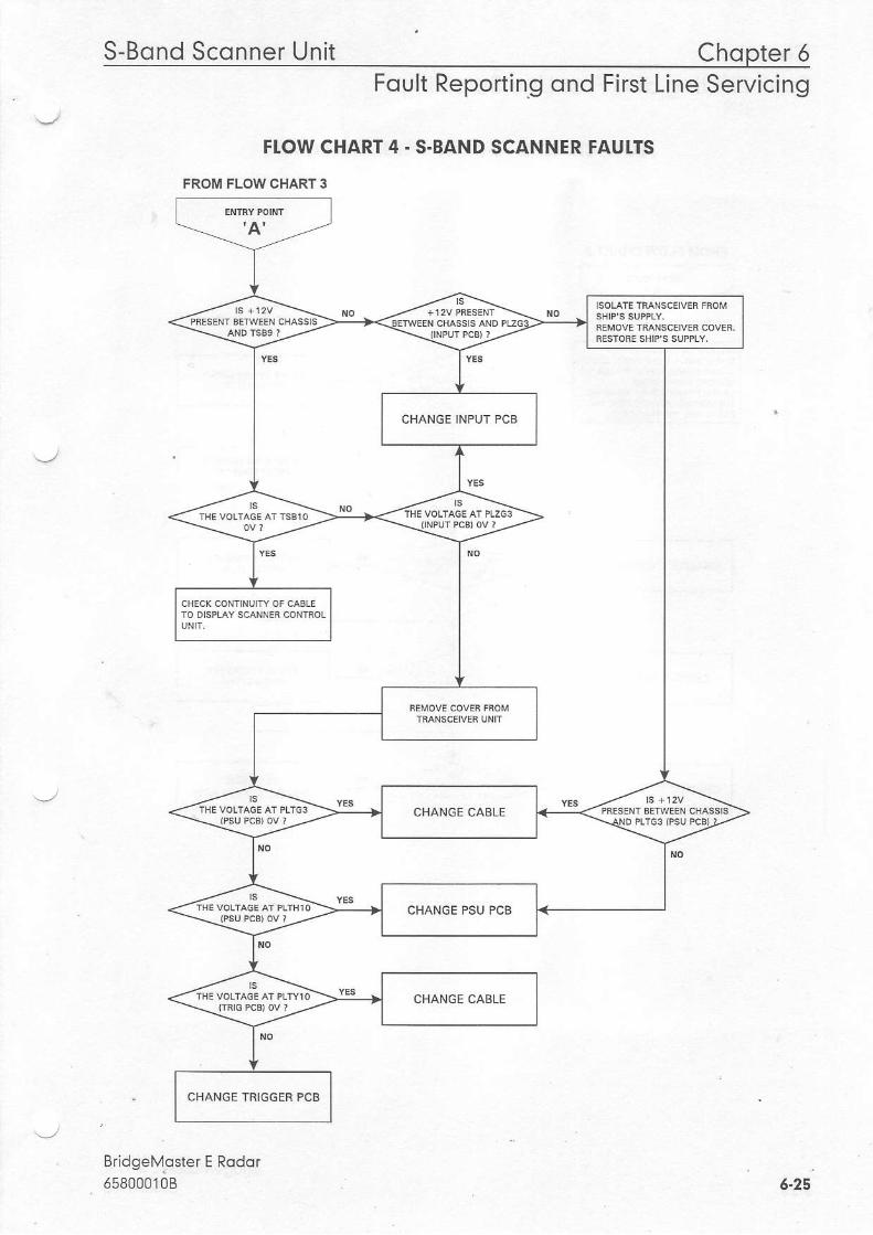
S-Bond Sconner Unit Chopter 6Foult Reporting ond First Line Servicing
FTOW CHART 4 . S-BAND SCANNER FAUITS
FROM FLOW CHART 3
Rr id^aM^( ta r F Pn. l ^ r
osaoootoa
CHANGE INPUT PCB
CHANGE PSU PCB
CHANGE TRIGGER PCB
6-25
Chopter 6 S-Bond UnitSco n nerFoult Finding ond First Line Servicing
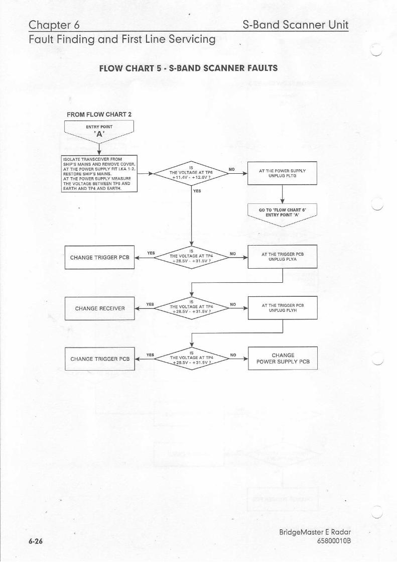
FIOW CHART 5 . S.BAND SCANNER FAUTTS
BridgeMoster E Rodqr658000'108
FROM FLOW CHART 2
CHANGE TRIGGEN PCB
CHANGE RECEIVER
6-26
S-Bond Sconner Unit Chopter 6Foult Reporting ond First Line Servicing
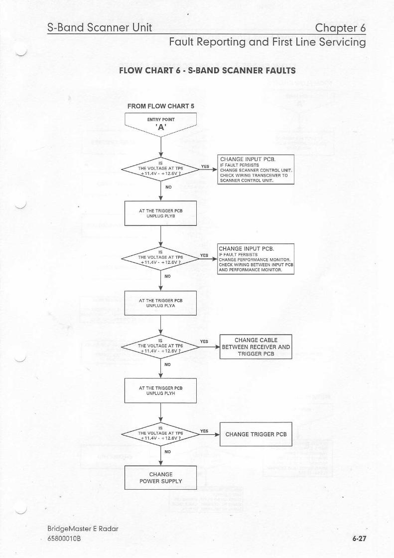
FI.OW CHART 6. S.BAND SCANNER FAUI.TS
BridgeMqster E Rodor658000108
FROM FLOW CHART 5
CHANGE INPUT PCB.
CHANGE INPUT PCB.
CHANGE CABLEBETWEEN NECEIVEN AND
TRIGGEB PCB
CHANGE TNIGGEN PCB
6.27
Chopter 6 S-Bond Sconner UnitFOUtt Frnorno ono Frrsl Lrne servrcrno
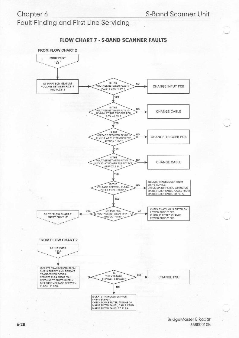
FTOW CHART 7 . S-BAND SCANNER FAUI.TS
FROM FLOW CHART 2
BddgeMoster E Rodor658000108
CHANGE INPUT PCB
CHANGE CABLE
FROM FLOW CHART 2
6.24
S-Bond Sconner Unit Chopter 6Foult Reporting ond First Line Servicing
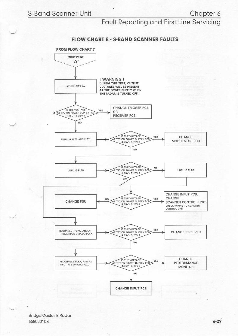
FI.OW CHART 8. S-BAND SCANNER FAUI.TS
FROM FLOW CHART 7
! WARNING !DURING IIIIS TEST, OUTPUTVOLTAGES WILL BE PRESENTAT THE POWER SUPPTY WHENTHE RADAR IS TURNED OFF.
BridgeMoster E RodorrseoootbB
CHANGE TRIGGER PCBORRECEIVER PCB
CHANCE INPUT PCB,CHANGESCANNER CONTROL UNIT.
CHANGE INPUT PCB
6.29
Chopter 5 S-Bond Sconner Unit
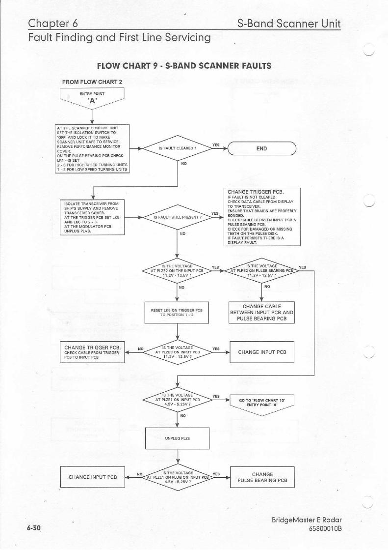
FROM FLOW CHART 2
CHANGE TRIGGEF PCB.
PULSE BEAFING PCB
CHANGE TRIGGER PCB.
Fqult Findino ond First Line Servicino
FLOW CHART 9 . S.BAND SCANNER FAUITS
BridgeMoster E Rodor6580001086.50
S-Bond Sconner Unit Chopter 5Foult Reporting ond First Line Servicing
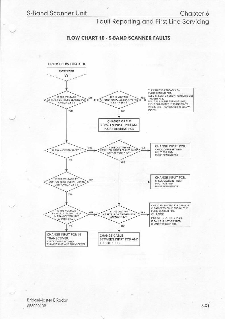
FI.OW CHART 10. S-BAND SCANNER FAUI.TS
BridgeMoster E Rodor65800010B
FROM FLOW CHART 9
|NPUTPcB|NTHETUFN|NGUN|T,
CHANGE CABLEBETWEEN INPUT PCB AND
PULSE BEAFING PCB
CHANGE INPUT PCB.
CHANGEPULSE BEARING PCB.
CHANGE INPUT PC8 INTRANSCEIVER.
CHANGE CABLEBETWEEN INPUI PCB ANDTRIGGER PCB
6-31
Chopter 6 S-Bond Sconner UnitFoult Finding ond First Line Servicing
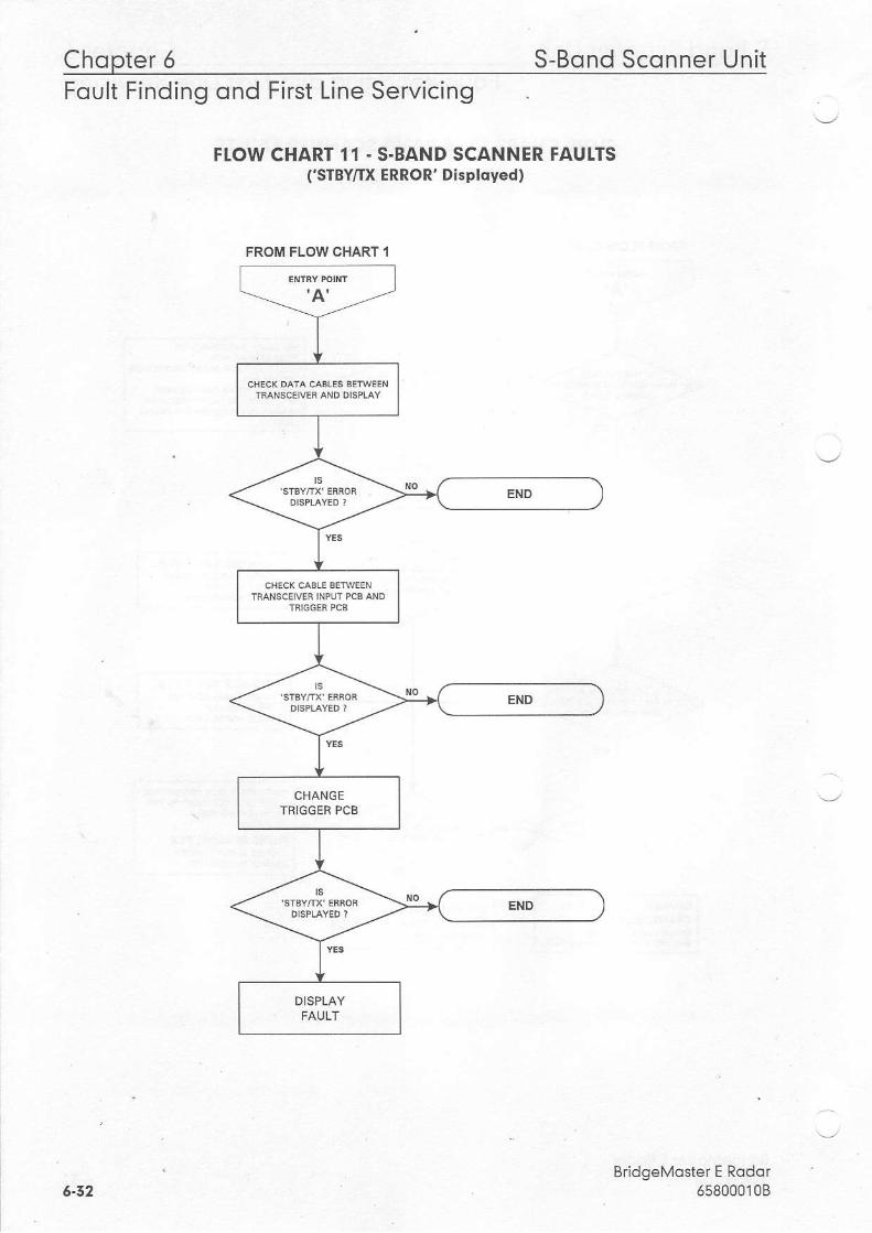
FTOW CHART 11 - S.BAND SCANNER FAUI.TS('STBY/TX ERROR' Dlsployed)
BridgeMoster E Rodor658000108
FROM FLOW CHART I
TNANSCEIVER INPUI rcb AND
CHANGETBIGGER PCB
5-32
S-Bond Sconner Unit Chopter 6Foult Reporting ond First Line Servicing
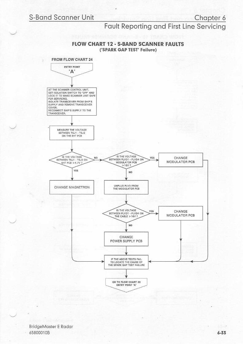
FI.OW CHART 12 - S-BAND SCANNER FAUI.TS('SPARK GAP TEST' Foilure)
BridgeMoster E Rqdor658000108 6.53
FROM FLOW CHART 24
CHANGE
Chopter 6 S-Bond Sconner Uni tFoult Finding ond First Line Servicing
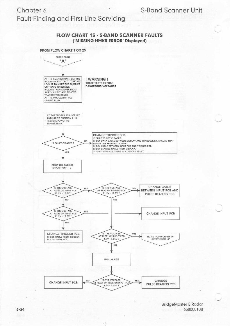
FIOW CHART 15. S.BAND SCANNER FAUI.TSCMISSING HMKR ERROR' Disployed)
I WARNING !
BridgeMoster E Rodor6580001085-54
FROIIII FLOW CHART I OR 25
CHANGE IRIGGEB PCS,
BETWEEN INPUT PCB ANDPULSE SEARING PCB
CHANGE TRIGGER PCB
CHANGEPULSE BEARING PCB
S-Bond Sconner Unit Chopter 6Foult Reporting ond First Line Servicing
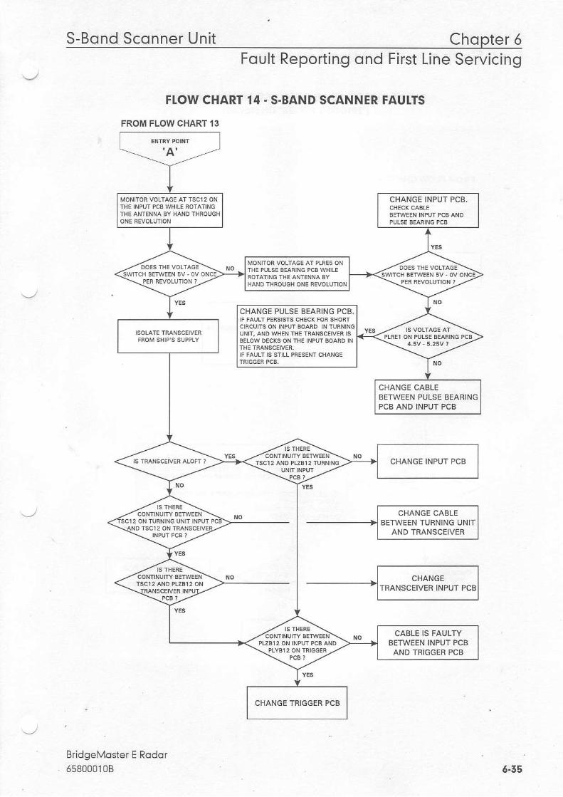
FI.OW CHART 14. S.BAND SCANNER FAUITS
FROM FLOW CHART'I3
BridgeMaster E Rodqr65800010B
CHANGE INPUT PCB.
CHANGE PULSE BEARING PCB.
CHANGE CAELEBETWEEN PULSE BEAFINGPCB AND INPUT PCB
CHANGE INPUT PCB
CABLE IS FAULTYBETWEEN INPUT PCBAND TRIGGEB PCB
CHANGE TRIGGER PCB
6.55
Chopter 6 S-Bond Sconner UnitFoult Finding ond First Line Servicing
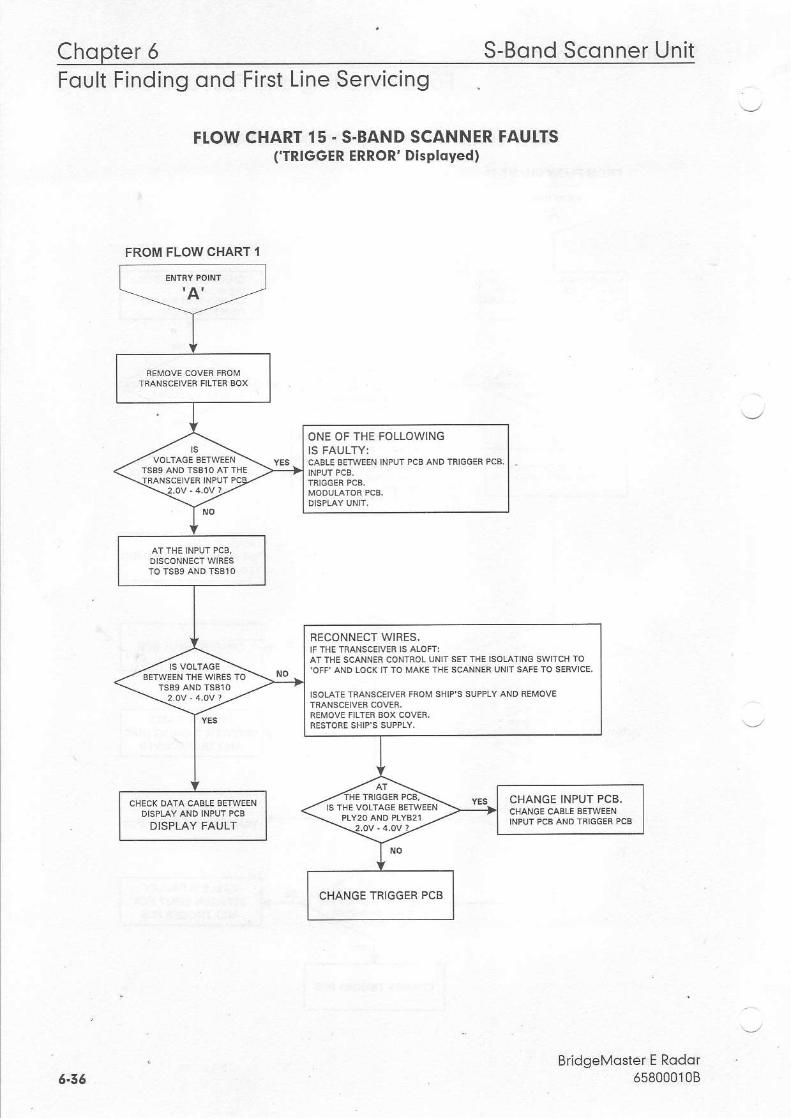
FI.OW CHARI 15. S.BAND SCANNER FAUI.TS('TRIGGER ERROR' Displdyed)
BridgeMoster E Rodor6s8000108
FROM FLOW CHART 1
ONE OF THE FOLLOWING
RECONNECT WIRES.IF THE TMNSCEIVEF IS ATOF|:AT THE SCANNER CONIROL IJiIIT SET THE ISOLATING SWITCH 10
IS THE VOLTAGI IETWEENCHANGE INPUT PCB.
DISPLAY FAULT
CHANGE TBIGGER PCB
5-36
S-Bond Sconner Unit Chopter 5Foult Reporting ond First Line Servicing
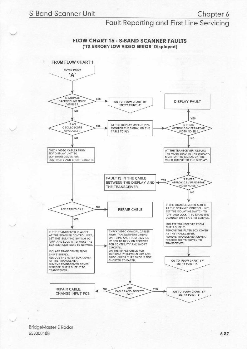
FIOW CHART 16 - S.BAND SCANNER FAUTTSCTX ERROR'/'IOW VIDEO ERROR' Displdyed)
BridgeMoster E Rodor55sooo10B
FROM FLOW CHART I
MONITOR IHE SIGNAL ON THE
FAULT I5 IN THE CABLEBETWEEN THE DISPLAY ANDTHE TFANSCEIVER
FEPAIB CABLE
ON THE I/P PCB CHEC( FOR
REPAIR CAALE.CHANGE INPUT PCB
5-37
Chopter 5 S-Bond Sconner UnitFoult Finding ond First Line Servicing
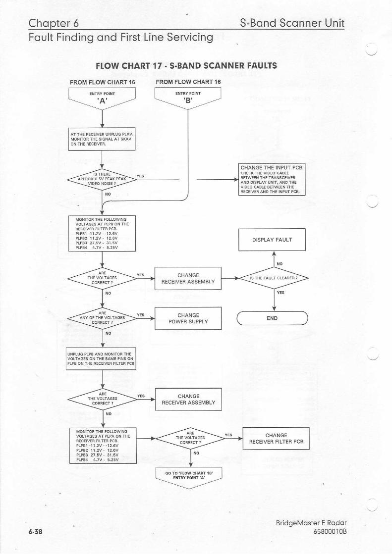
FI.OW CHART
FROM FLOW CHART 16
17 . S.BAND SCANNER FAUTTS
FROM FLOW CHART 16
BridgeMoster E Rodo.658000'1086.58
S-Bond Sconner Unit Chopter 6Foult Reporting ond First Line Servicing
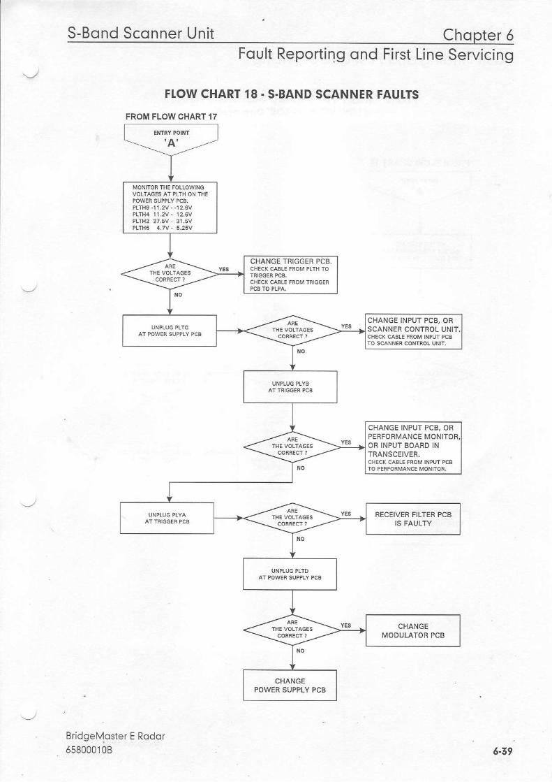
FI.OW CHART 18 - S.BAND SCANNER FAUTTS
FROM FLOW CHART 17
Bridgel'r'1oster E Rqdor65800010B
CHANGE TRIGGEF PCB.
CHANGE INPUT PCB, ORSCANNER CONTROL UNIT.
CHANGE INPUT PCB. ORPERFORMANCE MONITOFOB INPUT BOARD INTNANSCEIVER.
RECEIVEF FILTER PCB
6-39
Chopter 5 S-Bond Sconner UnitFoult Finding ond First Line Servicing
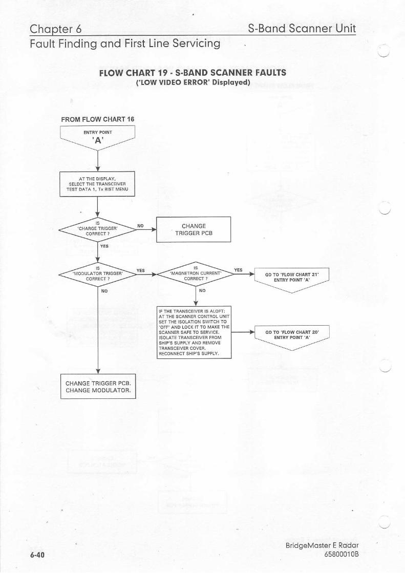
FI.OW CHARTrrow
19 . S.BANDVIDEO ERROR'
SCANNER FAUTTSDisployed)
'-,
BridgeMoster E Rodor658000108
FROM FLOW CHART ''6
CHANGETBIGGER PCB
CHANGE TRIGGEB PCB.CHANGE MODULATOR.
6.40
S-Bond Sconner Unit Chopter 6Foult Reporting ond First Line Servicing
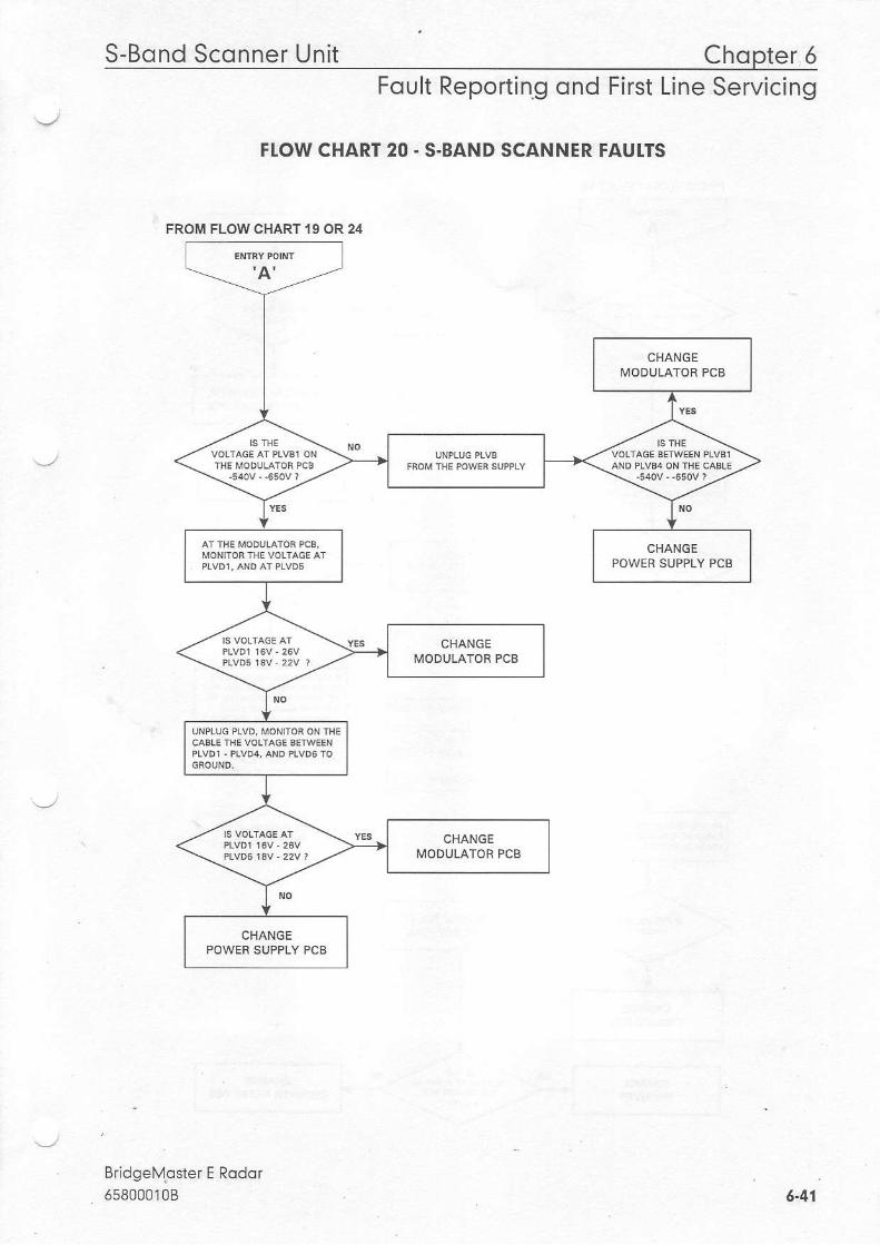
FI.OW CHART 20 - S.BAND SCANNER FAUI.TS
Bridgelvoster E Rodor558000108
FROM FLOW CHART I 9 OR 24
CHANGEMODULATOR PCB
6.41
Chop te r5 - . . S -BondSconnerUn i t
Foult Finding ond First Line Servicing
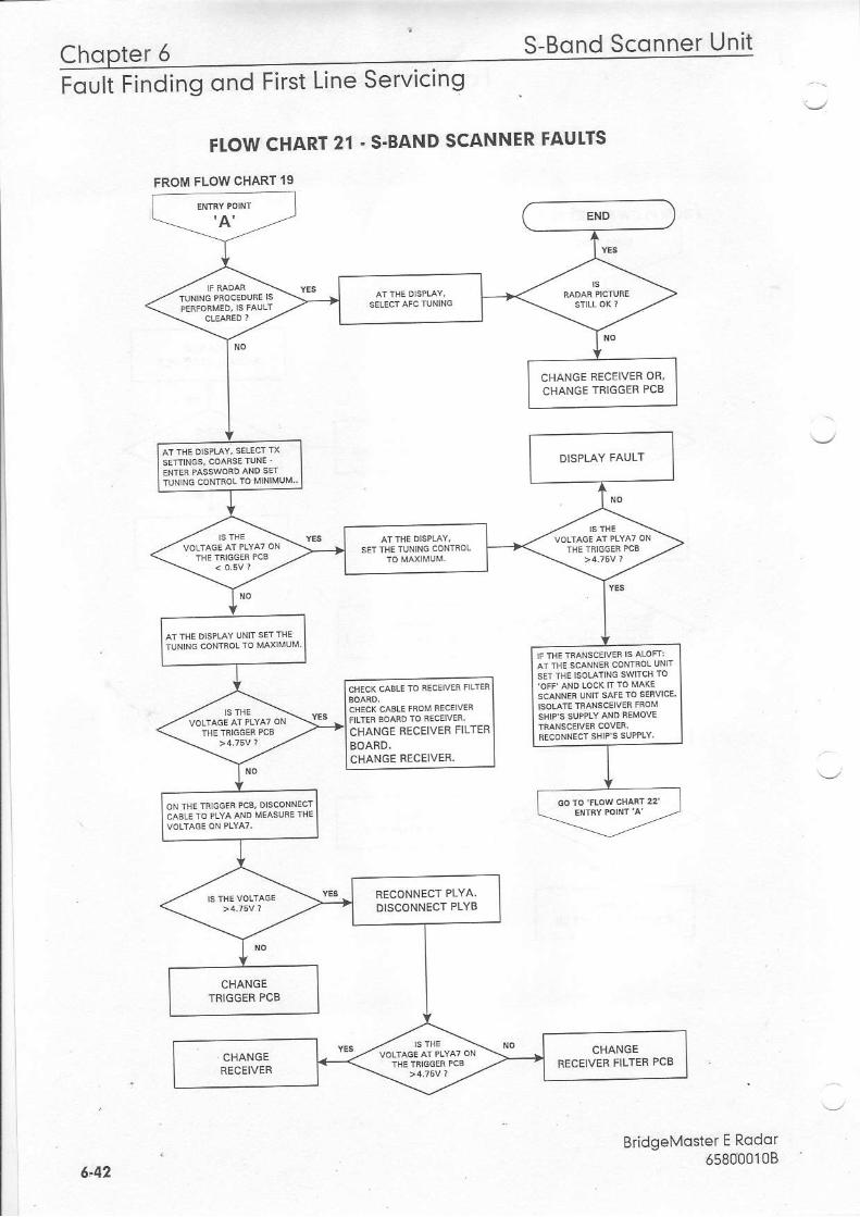
FTOW CHART 21 - S.BAND SCANNER FAUTTS
FLOW CHART 19
BridgeMoster E Rodor65800010B
FROM
CHANGE BECEIVEF OR,CHANGE TRIGGER PCB
CHANGE RECEIVER FILTER
CHANGE RECEIVER.
RECONNECT PLYA.DISCONNECT PLYB
6,42
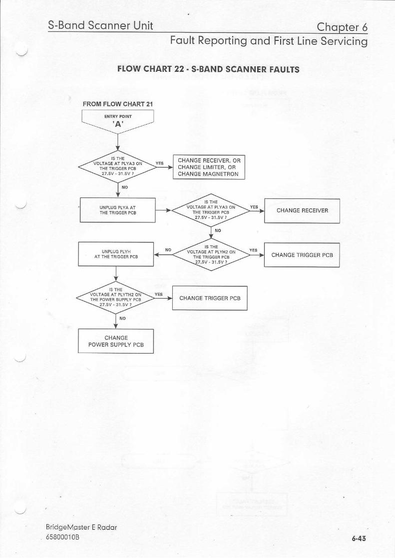
S-Bond Sconner Unit Chopter 6Foult Reporting ond First Line Servicing
FI.OW CHART 22 . S.BAND SCANNER FAUTTS
BridgeMgster E Rodor
FROM FLOW CHART 21
CHANGE RECEIVER, ORCHANGE LIMITER, ORCHANGE MAGNETRON
CHANGE FECEIVER
CHANGE TNIGGEF PCB
5.43
Chopter 6 S-Bond Sconner UnitFoult Finding ond First Line Servicing
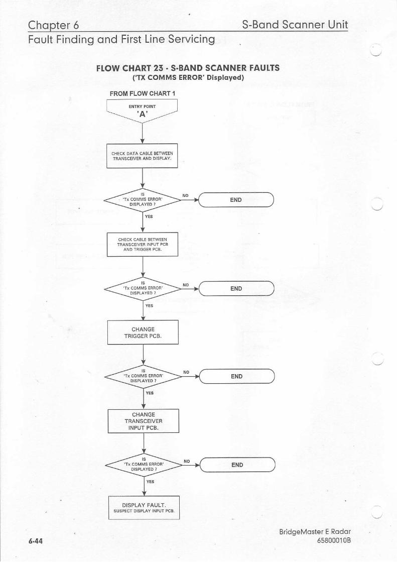
FLOW CHART 25 - S.BAND SCANNER FAUTTS('TX COMMS ERROR' Disployed)
BridgeMoster E Rodor658000108
FROM FLOW CHART 1
6.44
S-Bond Sconner Unit Chopter 5Foult Reporting ond First Line Servicing
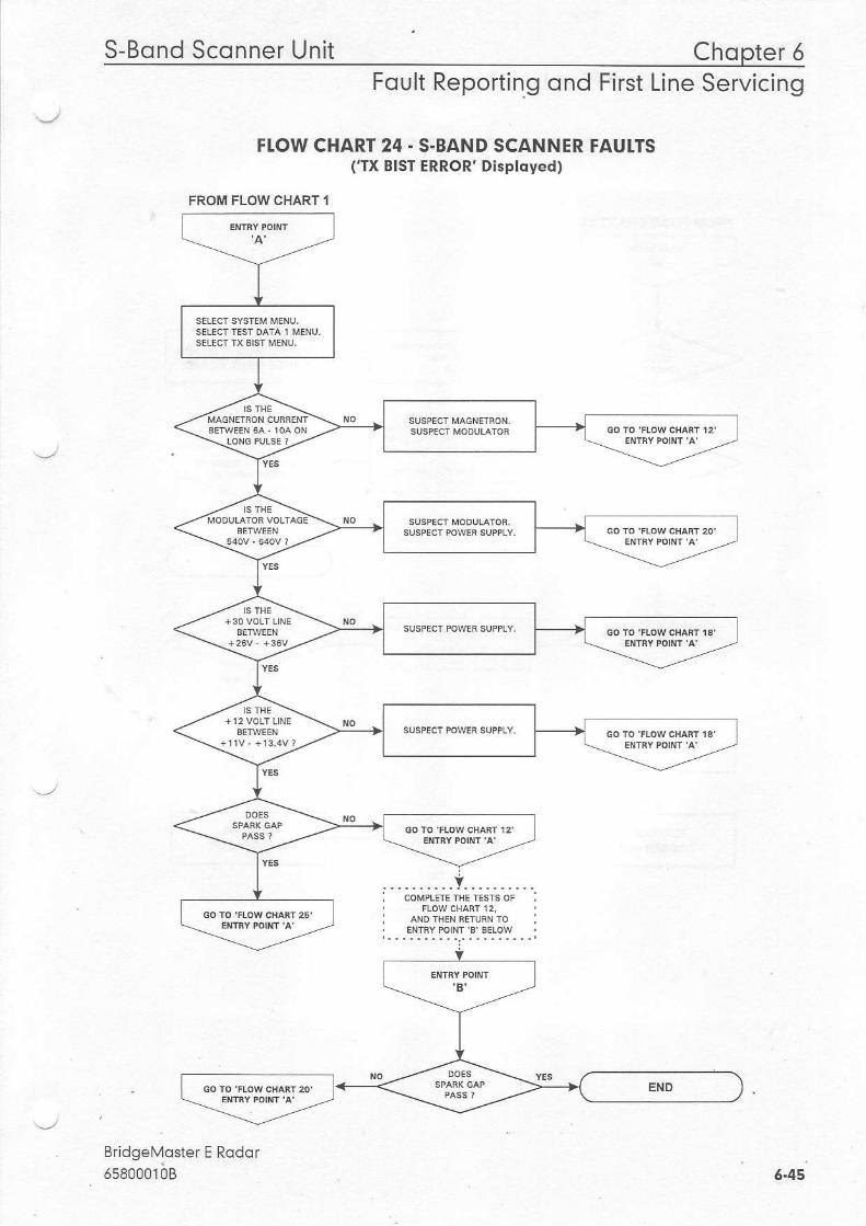
FI.OW CHART 24 - S-BAND SCANNER FAUITS('TX EIST ERROR' Disptdyed)
BridgeMoster E Rodorrseooorbg
FROM FLOW CHART I
6.45
Chopter 6 S-Bond Sconner UnitFoult Finding ond First Line Servicing
\.,
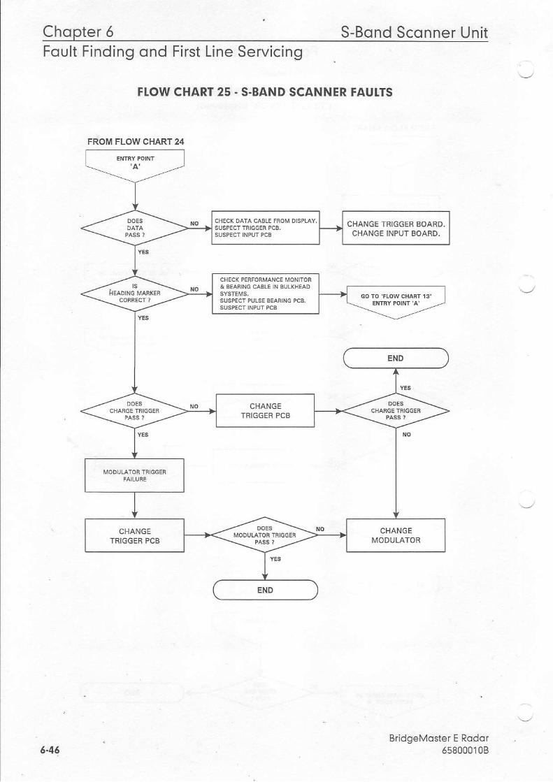
FLOW CHART 25 - S-BAND SCANNER FAUI.TS
FROM FLOW CHART 24
CHANGE TRIGGER BOARD.CHANGE INPUT BOARD,
t+y-;>*
EIID
\-
CHANGETBIGGER PCB
CHANGE CHANGETRIGG:R PCB MODULATOR
END
6-46BridgeMoster E Rodor
658000'10B

X-Bond Sconner Unit Chooter 6Foult Reporting ond First Line Servicing
2.5 X-Bond Sconner Unit
2.5.1 Technicol Descript ion
There are two basic types ofX-Band Scanner Unitr
with an integral transceiver modulewithout an integral transceiver
Each type can have a nLrmber ofvariants dependent on motor supply and the options thatare fit1ed.
The Scanner Unit comprises an Antenna, an antenna support casting, and a Turning LJnrt.
ncluded in the Turning Unjt is a motor and gearbox, a Bearing and Heading Marker pcb, anLnput pcb, and optionally a Perlormance llonitor and integral transceiver module.
The Transceiver Unit comprises, a base casting , a cover, atransceiver module, and an Inputpcb.
CommLrnication bet\r'r'een the Transceiver and the Display is by means ofa serial data link.Where a separate Tansceiver Unit is used, an RF feeder ( waveguide ) is used to transferthemicrowave energy beb/r'een the Transceiver Unit and the Turnjng Unit.
The Scanner Unit and the Transceiver Unt are compatible with BridgelYaster display units ifa Display Compatibility Unit is used.
Physicol ArrongementsThe Turning Unit is construcled from upper and lower aluminium castings. The uppercasting is hinged at one end to the lower casting for senr'ice and installation. The motor,gearbox and drive assembly are bolted to the upper casting. The transceiver module, whenfitted, is bolted to the upper casting and can be removed as a unitfor below deck servicing.
The terminal strips forthe interconnecting cables to other units are under a screen coveT onthe base ofthe lower casting. The Pedormance monitor is housed beneatf the upper castingand has a microwave transparent cover protecting it, fitted on the top sudace ofthe uppercasting
Four M l0 x 45 bolts are used to attach the Scanner Unitto the radar platform orwheelhouse roof. The Antenna is attached to the Turning Unit bythe Antenna SuppoftCasting and this directly transfers the microwave signals between the Turning Unit and theAntenna,
Interconnections between the Scanner unit and other units 1n the system are made usingscreened cables, with the exception ofthe Bulkhead system, where the microwave signalsare carried bel,veen the Tuming Unit and the Transceiver via a waveguide.
BridgeMoster E Rodor658000108 5-47
Chopter 5 X-Bond Sconner UnitFoult Finding ond First Line Servicing
Allthe cables that enterthe Scanner Unit do so via waterproof cable glands that incorporatean EIYC gasket that makes contact with the cable bmid.
The separate Transceiver is designed to be bulkhead mounted and is attached using four l4Bbolts, studs or screws (coachbolts).
TRANSCEIVER MODUTE OVERVIEW (X-Bdnd)
The transceiver module can be fitted in the Turning Unit, or mounted on a casting for belowdeck bulkhead mounting as a separate unit. The module incorporates the lYodulator pcb, aDowe' Srppry pcb. | '.gger pco, Lhe ReceiveJ . and the ric'owave conpo.e-ts.
Communication between the Transceiver Unit and the Display Unit is by means oftwoserial data link, one from the Transceiverto the Display Unit, and one from the Display Unit
\-'to the I ranscerver.
This information is transmitted using a special data cable that incorporates four twisted pairs.Two pairs are used for data transmission, one pair is used for trigger, and the other pair isspare.
The data passed from the Transceiver to the Display includes:
. Heading lYarker
. lncremental Bearing
. Transceiver Status
. Er.or lYessages
. BLirt In Ten Lquipnenr (BITE) data
. Tuning lndicator
The data transmitted from the Displayto the Transceiver includesr
. Standby/Transmit
. Pulse Lengh
. Tuning
. AFCA'lanual
. Sector Blanking
. Pedormance lYonitor Control, and Installation Settings.
Power SupplyThe power supply operates from the ship's AC mains, and provides all ofthe powerrequirements for the electronic modules within the Turning Unit and Transceiver. The ACmains is always present at the power supply even when the radar is switched offat thedisplay.
- lhe p een(e o'data on l l 'e serial oala l inl, M,he'the oisp'ay is switched on is deleaeo by
' the power supply, which then becomes active. .. ..-_,/
6-49 BridgeMosterE Rodar

X-Bond Sconner Unit Chopter 6Foult Reporting ond First Line Servicing
The power supply includes a Power Factor Correction circuit, and a number of switchlngregiJlators to generate the necessary voltage supplies. Overcurrent detection circuits protectthe power supply against ovedoads on its olrtputs.
Trigger PCBThe Trigger PCB processes the serial data from the Display Unit, and generates the requiredcontrol signals forthe Transceiver. lt monhors functions within the Transceiver, the HeadingMarker, and encodes the information fortransmission to the Display Unit. The data istransrnitted each tirne a bearing pulse is received from the Turning Unt. The various timingsignals required by the transceiver includlngthe pu se repetition frequenry (prf, areoanaato.l hw th6 triddFr n.h
Moduldtor PCBThe modulator pcb gene.ates the high voltage negative pulses required to drve the
' rnagnetron. The modu ator pulse widths and timing s gnals are controlled from the triggerpcb. A spa I gap on the modulator is fired ifthe magnetron falls to operate. Continuaoperation ofthe spark gap is detected and slgnal is fed back to the trigger pcb. When thetrigger pcb detects this signal rt switches the radar to standby, and genemtes an error signaltobe transmitted to the Display Unit via the serlal data link. The error signal causes the DlsplayUnit to switch to standby and generate an error alarm.
Microwove CircuiiTqe :ranc-ei,er employs a .o-ve-tional th-ee pon -i-l- lalor Lo di-ect .tre path o' .hemlcrowave energyto and from the antenna. A magnetron coupled to the circulator providesthe RF energy to be transmitted. A so id state limiter coupled to the circulator protects thereceiver from high powered microwave signals from the magnetron, or adjacent radars. Asignal from the trigger pcb is used to enable swept attenuation to be applied to the solid stateIn:te .o redu-e the srsle-n ,ens tivib/ ". sron ranSes.
ReceiverThe recejver consists ofa low noise amplifier, a mixer, a linear preampliier, a logarithmicamplifier, and a video amplifier. The 50lYHz output of the mixer is amplified by the linearpreamplifler followed by a logarithmic amplifier, the output of which is detected, the resultingvideo signal is then further amplified before transmission to the Display Compatibillty Unit.
The recelver also incorporates an AFC system. Once the receiver has been tuned, the AFCsystem ensures that the receiver remains on tune during variations in tuning due to thermaldrift ofthe mixer and magnetron etc.
The operator can select beflveen manualtuning and automatic tuning. A signalfrom thetrigger pcb is used to select the mode ofoperation. A signalfrom the AFC circuit is fed to thetrigger cjrcuit to indicate the state oftune ofthe receiver. This signal is at ib minimum valuewhen the receiver is correctly tuned,
BridgeMoster E Rodor65800010B 5-49

Chopter 5 X-Bond Sconner UnitFoult Finding qnd First Line Servicing
AUTOMATIC START-UP SEOUENCE (X-Bond)The automatic starl up sequence described below, should be read in conjunclion withFigures 6.4 'X Band Turning Unit (Aloft) Schematic'.
Stort.uplmporldnt Notice - Once mains is applied to the PSU board the Power Factor Coffectton(PFC) circuiLy starts and generates 39AV ft shauld be noted that wht:lst mains is applied thePFC is active and cannot be manual, switched off The stuft circuttry only controls the flybackconverter so Hrgh Vo/tage DC b present on primary power companents whenever malns Bpresent an the board. This ldct should be noted when seruicing the lrdnsceiver.
The Power Supply in the Transceiver is only active during normal operation when there is aDlsplay (or Compatiblllry Unit) connected to it. The RS422 serial data stream from theDisplay is used to drive an opto-coupler in the PSU which detects the presence ofeitherpolarity voltage and enables the flyback converter in the PSU.
RS422 seial data stream from the Display enters the Input Board on connector| , 2 as "DU DATA+ and DU DATA-'. lt is then passed to the Trigger Board via PLYB7, and then on to the PSU via PLTH I | , l2 (as PSU START and PSU START RTN).
Fortest purposes the PSU can be turned on in the absence o{a serial data stream by linkingpins | 2 on LKA (PSU).
Tronsmit EnobleWhen the operator selects Transmit, the TU Enable signal is adtvated LOW on the TriSSerPCB ( PLYI | 0). On the X Band Scanner Unit, this signal is fed to the Power Supply unrtand via the Turning Unit On/Of and InpLrt PCB to the Motor Drive PCB to staft the antennarotating.
Once the antenna has done one complete revolution transmission is staded. When standbyis selected, transmission ls immediately halted and, after one complete revolution oftheantenna, TU Enable is disabled.
The lYodulator stafts to generate radar pulses when the Trigger PCB sends it l4ODTRIGGER pulses (to PLVC 9). Note thatthe CHARGE TRIGGER puises (on PLVC 8) arepresent even in Standby mode.
A signal indicating that the lYagnetron has flred is fed via MAG SAIYPLE from PLVC 7 on thelYodulator PCB to the Trigger PCB. This signal is processed on the Trigger PCB andoutputted as TX TRIG (PLYB 20 & 2l) to the Input PCB (PLZB 20 & 2l) and then to theDisplay Unit via TSB 5 & 6.
Note - 7X DATA is sent from the Tnnsceiver to the Display UnrtDU DATA is sent from the Display Unit to the Transceiver Unit.
TheTSB
BridgeMoster E Rodor65800010B6.50

X-Bond Sconner Unit Chopter 6Foult Reporting ond First Line Servicing
The Trigger PCB processes the serial data inpLt from the display, and generates the requiredcontrolsignals forthe Transceiver.The data is transmitted each time a bearing pulse isreceived from the Turning Unit. The various timing signals required bythe Tmnsceiverincludingthe Pulse Repetition Frequency (PRD, are generated by the Trigger pcb.
Mdgnetron OperotionThe high-voltage negative pulses required to drive the magnetron are generated bythelYodulator PCB. The modulator pulse widths and timing signals are controlled from theTrigger pcb. A spark gap on the flodulator is fired ifthe magnetron fails to operate.Continual operation ofthe spark gap is detected and a signal is fed back to the Trigger pcb.
On detection ofthis signal, the Trigger PCB switches the radar to Standby, and generates anerror signalwhich is transmitted to the Display Unit viathe serial data link. The error signalcauses the Display Unitto switch to Standby and generate an error alarm.
When Standby is selected, rotation ofthe Antenna is inhibited. Unless in Test Mode,transmission from the radar is inhibited ifthe Antenna is not rotating.
On the Trigger PCB, there is a timer circuit which is basically a capacitor that slodydischarges (belveen 4s and l8s) when power is removed from the PCB. On power up themicrocontroller measures the charge remaining on the capacitorto determine whetherthetmnsceiver has been switched of for long enough to warrant inhibiting transmit forthreerninutes until the magnetron heaters have had time to warm up again.
The other analogue signals into the Trigger PCB come from the lYodulator. The lYod!latorsupply voltage and the magnetron current (only when transmitting) are measured and senttothe Display as an aid to faultlinding. The sparkgap detect signal is generated bythemodulator when the magnetron arcs over, if it reaches a predetemnined level themicrocontroller inhibits transmission for approximately one second and sends an errormessage to the Display.
BridgeMoster E Rodor658000108 5-51

Chopter 5 X-Bond Sconner UnitFoult Finding ond First Line Servicing
TURNING UNIT OVERVIEW (X-Bond)
Drive SystemThe scanner motor is a 3-phase eleclronically con rnutated DC motor. The motorcommutation drive signals are provided bythe ['1otor Drive pcb which has the capability ofprividing High and Low speed operation by llnk selection. The lYotor Drive pcb is suppliedwith +50VDC from the Tmnsceiver power supply ( in both Aloft and Bulkhead fits ).
The motor drives an integral 32r I reduction gearbox. The output ofthe gearbox drives apulley system with a slngle toothed beit having a reduction ratio of 3j | . The final pulley isattached to the AntennatorqLre tube assembly. The overal reduction betv/een the n]otorand Antenna is aporoximately 96:1.
When standby is selected, rotation ofthe Antenna s inhibited. Unless in test mode,transmission from the radar is inhibited ifthe Antenna is not rotating. An isolating switch isprovided for AC systems to switch the scanner motor supply offor safe servicing
Motor Drive Boord(lncorporoting the Dynomic Broke lqcility)The lYotor Drive PCB generates the supply and control signaLs forthe 3-phase electronicallycommutated DC motorthatturns the Scanner Unit. The Motor Drive PCB has the capabiliryof provid ng High and Low speed operation by llnk selection on the PCB
The Motor Drve PCB is supplled with *50VDC from the Transceiver power supply ( rnboth Aoft and Bulkhead fits ).
Pulling control llne 'TU Enable' below 1.5 volts starts a slow buid up of speed up to themaximum set bythe speed selection link. The 6 outpLrt FET switches which perform thecommutation, are protected by a current senslng and limiting circuit, in the event ofoverloadoT sra t.
Signals from the Hal Sensors in the motor are used to control the commutatlon sequence,and are also used to provide a degree of speed compensation in hlgh wind load conditionsAn additionalfeature ofthe PCB is a Dynamic Brake which prevenis the antennafrom'windmllling' when the radar is turned offor on standby. This circuit is passive and wioperate with no supply voltage.
Beqring ond Heoding Mcrker SystemA disc wlth | 28 teeth is attached to the Antenna torque tube and combined with an opto-coupler generates l28 pulses per rotation ofthe Antenna.
A second opto couplertogether wlth aflag on the toothed disc generates a Heading Markerapproxirnately l0' before the Antenna is pointlng dead ahead. Correct alignment oftheHeading l'larker is set at installation by electronic adjustment within the Display Unit.
Both opto-couplers are on the Pulse Bearing PCB. The Pulse Bearing PCB multiplies thebearing pulses by 32 to generate 4096 pulses perAntenna revolution. The 4096 azimuth
t28
6.52BridgeMoster E Rodor
65800010B

X-Bqnd Sconner Unit Chopter 5Foult Reporting ond First Line Servicing
pulses and the heading marker are roLrted through the Input PCB to the Trigger PCB wherethey are incorporated into the serial data to be transmitted to the Display Unit.
A jumper link LK I is fitted to the Pulse Bearing PCB to select High or Low speed operation.The link should be set belr',/een pins | & 2 for Low Speed operation ( Factory Default ). ForHigh Speed operation, pins 2 & 3 should be used. Note that if no link is fitted, the default isHigh Speed operation.
Where it is not possible to adjustthe Heading marker alignment at the display, optional extracircuitry can be fitted to the Input pcb to allow the alignmentto be made eleclronically withinthe Tuming Unit. When this option is itted an additional ( isolated ) Heading lYarker outpLrtis provided. As an option for special applications a size I I synchro can be fitted as anahemative source of bearing information.
lnterconnectionsThe terminations for interconnections forthe Transceiver and the Tuming Unit are under acover on the inside ofthe lower casting ofthe Tuming Unit. The AC power from theisolating switch is terminated at a terminai block within the filter box on the inside of thelower casting ofthe Turning Unit. All other connections are made to plugs or removableterminal strips on the inpLrt pcb.
BridgeN4oster E Rodor658000108 6.55

Chopter 6 X-Bond Sconner UnitFoult Finding ond First Line Servicing
TRIGGER PCB (X Bond)
Generol DescriplionThe Trigger PCB controls the operation ofthe Tmnsceiver under instnrction from theDisplay. There are Mo serial link, which are used to transfer control messages from theDisplayto the Trigger PCB and Transceiver information back to the DispLay. The TriggerPCB generates the control and tuning signals required bythe 1'4odulator, Receiver,Performance lYonitor and Biased Limiter. The PSU is enabled with a signal from the TriggerPCB.
Signols To /From the Trigger PCBTolFrom Display
Se'ial Data lo DisplaySerial Data from Display
' Triggerto Display
To,f rom ModulatorPulse Length select linesCharge and lYodulator TriggerslYagnetron Heater Turndown signal ( only used for S-Band, Long Pulse operation )Voltage/Cu rrent 14onitor signalsl025kW and S-,X-Band Conliguration signals
To/From ReceiverTuning Voltage signalBandwidth Control signalAFC,4Yanual controlAFC TriggerTune Indicator signal
To Biased LimiterTrigger signal
To Pedormance lYonitorOn/Offsignall"lode Control signalTuning Voltage signals
TolFrom Power Supply PCB+30V, + l2V, +5V, 0V & - l2V Supply linesTurning Unit EnablePower Supply Start and Return
BridgeMqster E Rodor6580001086.54

X-Bond Sconner Unit Chopter 6Foult Reporting ond First Line Servicing
FUNCTIONAT DESCRIPTION (X-Bond Trigger PCB)
The 80C51 family microcontroller provides overall control ofthe Trigger PCB functions.Program rnemory and RAIY are included withjn the microcontroller iC. Serial l/O is handledby the microcontrollers internal UART and an e>,ternal RS422A driver and recelver. Baudrate is fxed at 76800 baud for operational use but is link selectable to 19200 or 38400 baudfortest purposes. The serial data format is I bit data, I stop bit and even parity.
The Display sends serial messages comprising four or ive characters depending on messagecontent. Control messages are four b)4es long and tuning messages are five. The tuningvoltage levels are sent as l2-bit lalues which are convefted onthe Trigger PCB using afour-channel DAC before amplification,/bufering and distributlon to the Receiver and PerformancelYonitor.
The Bearing signal from the Turning Unit is used to injtiate serial transmission from theTrigger PCB such that each time one ofthe 4096 azimuth pulses per rev is generated andfed into one ofthe microcontrollers interrupt pins, a character (one b)te) is sent to theDisplay. One bit in each ofthe characters sent ls dedicated to the heading marker, on everynew heading marker pulse from the Turning Unit, the bit is toggled.
The Power Supply in the Transceiver is on y active during normal operation when thereDisplay (or Compatibility Unit) connected to lt. The RS422 seria input from the Displayused to drive an opto isolator which detects the presence of either polarit/ voltage andenables the PSU.
Trigger OuputsThere are a number oftrigger signals generated by the Trigger PCB:
Pre-TrlggerCharge TriggerModulator TriggerDisplay TriggerPedormance lYonitor TriggerAFC Triggerq\^/a^t A|lF^ ,)ri^n l.itiata
The Charge Trigger is the timing signal used to recharge the Modulator PFN. This isgenerated bythe microcontroller using an internaltimer routine set to the appropriate PRFfor the pulse length selecled. Awobbulation factor is added to the basic timing to ensure thatno tuvo radar transmissions are locked together. The wobbulation is calculated according tothe number of serial messages received before going to transmit and the position oftheantenna behr'r'een each trigger pulse.
An optional Pre-trigger will be produced approximately 1 lps before the modulator trjgger.This is not a normallyftted option and is intended for use in Speclal Options applications.
i s ais
BridgeMoster E Rodor658000108

Chopter 6 X-Bond Sconner UnitFoult Finding ond First Line Servicing
The lYodulator Trigger is used to let the charge out ofthe PFN into the magnetron and isthe triggerthat initiates the modulator llring. lt is delayed from the Charge Trigger by l00psand gated offwhen the transceiver is in standby.
In standby, the Display and Perlormance Monitor Triggers are generated from the lYodTrigger pulse. When the transceiver is in transmit mode the triggers begin on the leadingedge ofthe magnetron sample pulse and end after a preset time, adjustable using RV | .
The AFC Trigger is used by the receiver when in AFC mode and is onJy generated when thetransceiver is ln transmit mode. The pulse is starLed on the front edge ofthe lYodulatorT.gg"'aro .er_ni_ates o_ .he oa(|. ecge o[ .^e l.]agne_'on ia'role oL se.
The Swept Attenuation Initiate pulse is the timlng slgnalfed to the Limiter Ddve PCB whichgenerates the controlforthe biased limjter. lt ls injtiated bythe front edge ofthe Pre-trigger(approximately 2ps priorto magnetron llrlng) and terminated 2.5ps afterthe leading edge ofthe magnetron sample pulse.
The Dlsplay and Pf4 Triggers are essentiallythe same trigger and are present at alltimeswhen the radar is powered up. They are initiated by the Yodulator Pulse and last forapproximately 2.5ps.
Anologue OutputsThe Trigger PCB generates four tuning signals; LO.Tune, PIY Tune, Xr Adjust and XtAdjust.These signas are coded as l2 bit digital valles and incorporated into the serial messagesfrom the Display. A 12-bit, four channe DAC is used to generate the tuning signals from themessage data. Additional bufering is added to the LO and PIY Tune outputs ofthe DAC andx3.5 ampllfication to the Xr and Xt Adjust signals.
LO Tune is the 0V to +5V receiver tuning control and PIY Tune the 0V to +5VPerformance Monitor main tuning control. Xr and Xt Adjust are 0V to + 5V signals used tocontrolthe receive and transmit altenuato|s in the Pedormance lYontor.
Analogue lnputsThere are i,arious analogue inputs to the Trigger PCB from other PCBs in the transceiverand some on board slgnals that are fed into an eight channel 8-bitADC, and converled todigital values eitherforfufther processing by the microcontroller orto be passed to theDisplay viathe serial message link.
The signals on the Trigger PCB that are rneasured are the dropouttlmer and + 2V andi30V supplies. The timer circuit is basically a capacitor that slowly discharges (between 4sand 1 8s) when power is removed from the PCB. On power up the microcontrollermeasures the charge remaining on the capacitor to determine whetherthe transceiver hasbeen switched offfor long enough to warrant inhibiting transmit for three minutes untilthemagnetron heaters have had time to warm up again. The power supply levels are measuredand the results sent to the Display as an aid to fault diagnosis.
6-56BridgeMoster E Rodor
65800010B
X-Bond Sconner Unit Chopter 6Foult Reporting ond First Line Servicing
One channel ofthe ADC is used to detect whether a Performance lYonitor has been frttedto the system. The voltage on this channelwill be lowefthan a preset value ifa PedormancelYonitor is present otherwise it will be pulled to the +5V suppiy rail. This information sencoded and sent as part ofthe configuration message to the Display.
The Receiver sends a tune indicator signal to the Trigger PCB which indicates how close it isto being on tune. This signa is coded as parl ofthe serial message and sent to the Display.
The other analogue signals into the Trigger PCB come from the lYodulator. The l4odu atorsupply voltage and the magnetron current (only when transmitting) are measured and senttothe Display as an aid to faultlinding. The spark gap detect signal is generated bythemodulator when the magnetron arcs over, if it reaches a predetemlined levelthernicrocontrol er lnhibits transmission for approximately one second and sends an errormessage to the Dlsplay.
Digitol OutputsThe digital outputs from the Trigger PCB are all straight fo^r'r'ard on/off control signals tov , . r^ ' ' r ^ rd . ^ { fhF +r rn ( .F wFr
Signals to the Receiver se ect wide or narrow bandwidth 0r'r'ideband) and AFC or manuaLtuning mode (AFC On). Narrowband is selected when the modulator is transmitting in longpulse and briefly during pulse lengh changing. AFC or manual mode is selected by the radaroperator and is paft ofthe contTol message sent from the Display.
lYodLrlator signals faP and SP are used to set the pulse length as requested by the radaroperator, SP set to 0V lndicates shoft pulse operation, IYP set to 0V indicates medium pulseoperation and both SP and IYP setto +5V indicates long pulse operation. SP and Y1P bothset to 0V is an illegal state and will not happen in normal operation. Turndown enable ls usedto reduce the heater current in the magnetron and is only set when an S Band magnetron isfitted and is transmitting in long pulse.
The control signals PIY On/Off and PY Tx,Rx are used to switch the Performance lYonitoron and to switch it belMeen system test mode and rece vertest mode,
TU Enable is the control signal fed to the f4otor Drlve PCB to initiate rotation oftheantenna. When the operator selects transmlt the TU Enable signal is activated to staft theantenna rotatlng.
Once the antenna has done one complete revolutlon transmission is started, When standbyls selected, transmission ls immediately halted and, after one complete revolution oftheantenna, TU Enable is disabled,
Oprionol l/OThere are seveml optional /O signals for use with Special Options variants of the PCB; Pre-trigger (as described in the section on triggers), External Trigger Input and Radar Inhibit. TheExternal Trigger input is used when the modulator needs to be triggered from an external
BridgeMoster E Rodor658000108 6.57

Chopter 6 X-Bond Sconner UnitFoult Finding ond First Line Servicing
source mtherthan the Trigger PCB. Trigger signals fed to this input are prf limited to preventdamage tothe modulator. Radar Inhibit is a method of inhibiting transmission without usingthe appropriate command in the serial message. An active signal at this inpLtwill cause them crocontro ler to inhibit transmission within one trigger pulse at either ofthe internal p.fs.
Built In Self Test (BIST)The microcontroller pedorms a number ofselftest operations and reports the results to theDisplay as part ofthe serial message link. Error situations that are monitored in thetransceiver are; serial message corruption, loss of Display messages, loss of Heading Markersignal, loss of either Charge or lYodulator Trigger and magnetron arcing. Error situations willin all cases cause the microcontroller to inhibt transmission untilthe error has been cleared.The other signais that are monitored and sent directly to the Display withoutfurther actionbythe microcontroller are the power suppiy lines and magnetron current as described in thesection on analogue inputs.
Test ModesThere are two test modes for the Trigger PCB. The production test mode is used solelydLrring production testing ofthe PCB and is initiated by fitting the test link LK4. This must onlybe done on the production test bed as connectingthis link when incorporated into atransceiver could lead to unpredictable and possibly dangerous operation.
The second test mode, ofuse to service engineers can be injtlated by fitting the |r',/o linkLK5 and LK5 to Dosition 2-3. When in thls mode the transceiver can be removed from theturning unit, reconnedled to the Display below deck (with suitable test cables) and run asper normal operation. A dummy load IYUST be connected to the RF output. Since theTransceiver has been removed from the Tuming Unit and the Pulse Bearing PCB outputs,the bearing and heading marker information normally required for Trigger PCB operation issimulated on a section oftest circuitry on the Trigger PCB.
BridgeMqster E Rodor65800010B

X-Bond Scqnner Unit Chopter 5Foult Reporting ond First Line Servicing
TRANSCCIVER POWER SUPP[Y (X-Bond)
Generdl lntormqtionThe power supply is an AC to DC invederthat generates the supplies forthe Transcelver.The inverter is housed on a single board and is powered by an AC supply of nominal I l5Vor 230V in the frequency range 47-6412.
The power unrt uses a boost converter front end to provide a regulated high voltage d.c. toa flyback convefter providing the output supplies. Some ofthese supplies use additionalswitch mode converters to provide regulated odputs.
The outputs supplied bythis power supply arei-Variab e 600V, +30V, +20V, magnetron heaters (via fudher regulalor, + l2V, - l2V and+ 5V) and for the X-Band Turning Unlt vadant, +50V for the f4otor Drive pcb.
| -e power unrr ras rhe follow_g 'ealLresl
. 600V adjustable over the range -550Vto -550Vfor control of magnetroncurrent via modulator.
. nr tar ' <hor . ; . . r r i i r -^rc-;on.
. Universal input from 95Vto 2T6Vwithout tap changing. Power facror corrededproviding a PF ofbetterthan 0.9.
To switch the flyback convefter on the opto-coupler detects the presence of a serial datastream from the display at PLTH ll, 12. On detection ofthe data stream the phototransistor within U5 is turned on pulling down the gate of Q2 below its threshold voltage.Q2 turns of allowingthe compensation pin I U4 to rise enabling output ofthe lC U4. In thePSU off state Q2 is held on by current in R37 from Vcc.
For test purposes the PSU can be turned on in the absence ofa serial data stream by llnking| 2 on LKA.
Note that once the mains supply is applied to the PSU board, the PFC (Power FactorCorrection) circuit staris and generates 390V, Whilst mains is applied, the PFC is active andcannot be manually switched off The staft circuitry only controls the flyback converter andso High Voltage DC is present on primary power components whenever mains is presenton the board. This locl should be noled when seruicing the Tlonsceiver.
MODUTATOR PCB (X-Bqnd)
Functionql DescriptionThe principal functlon ofthe lYodulator PCB is to generate an BkV, BA negative pulse todrlve the cathode ofthe magnetron. An SCR is used to resonantly charge a Pulse FormingNetwork (PFN) to - 200V from the -600V iYodulator HT supply. The charging cycle isinitiated by the Charge Trigger. The number of seclions ofthe PFN is selectable by the
BridgeMosler E Rodor65800010B 6.59

Chopter 6 X-Bond Sconner UnitFoult Finding ond First Line Servicing
rela)as controlled bythe Pulse Len$h Control Lines. The number of sections ofthe PFNused dellnes the length ofthe outpr,t pulse.
At a deined time afler the PFN is fully charged it ls discharged by three series connectedInsulated Gate Bipolar Transistors through a pulse transformer. The discharge is initiated bythe lYodulator Trigger. The Pulse Transforn er, which has step up ratio of l2: | , transformsthe resulting pulse to BkV. The back edges ofthe mediltm and shoft pulses are speeded uPby a saturable reactor connected across the prlmary ofthe pulse transformer.
Other functions include regulating the magnetron heater supply, monitoring a spark 8ap toensure correct operation ofthe magnetron, and generation of atiming reference fortheRadar Trigger.
Inputs to the f4odulator PCB' 600V Modulator HT Supply
*20V Modulator Trigger Supply+ 6V - +27V lYagnetron Heater Bulk Supply+ l2v-t2v
.-,
Short Pulse Control LinelYedium Pulse Control LineCharge Trigger
M^d,,l:i^r Tridocr
Turn Down Enable
Outputs from the lYodulator PCBPrimary sample
l'lagnetron current sample
TX Active
when 0V se ects short pulse,u/ha^ n \ / cF la . r . mF. l i , ,m n , , l<F
initiates charging of Pulse Forming Network. TypicallylAmp current pulse.initiates discharge of Pulse Forming Network. Typically4us, 3.5V positive pulse.dc voltage controls the magnetron heater voltage. 0Von long pulse, 3.5V Standby iYedium and Shod Pulse
positive pulse sample from pulse transformer used toinitiate Radar Trigger. Typically 40V amplitude.a dc voltage propoftionalto the magnetron currentderived from the secondary ofthe pulse tEnsformer.Typically +2.5Va signal that is normally 0V that rises to > 2.5V if thespark gap operates continuouslyfor 2 seconds. Thissignal is used by the Trigger PCB to indicate atransmitter faultto the display.sample of lYodulator HT Supply fed to TriSger PCB forinclusion in BITE message sent to display.Li.k.efl ings Jsed to aefi1e mod-lato'$pe lo T ,gge'PCB. 0V or 3.5V dependant on link settings.
BridgeMoster E Rodor65800010B
HT Sense
TX Define
6.60

,J
Bf ldgeMoster t Rodor65SO0o1oB
X-Bond Sconner Unit Chopter 6Foult Reporting ond First Line Servicing
Mqgnelron Heoler SupplyThe magnetron heaters are derived from the lYagnetron Heater Supply at PLVD I andPLVD2. This supply may \ary between 16V and2N.
The Modulator PCB is conllgured forthe intended magnetron by the setting of link LKI fitredto the lYodulator PCB. Referto Figure 5. B'LinkSettings lYodulator PCB', in this chapter,for further information.
WARNING - On no dccount shoald he hedler volrdge be meosured whilst lhefrdnsceiver is lrdnsmitring,
In a l0lQV X-Band system, the magnetron requires a heater voltage (measured betweenTSI I and TSJ2) of 6.lV on Standby, Short Pulse, lYedium Pulse and Long Pulse.
' In a 25KW X Band system, the magnetron requires a heater voltage (measured betweenTSI I and TSJ2) of 6.lVon Standby, Short Pulse, and Medium Pulse. On Long Pulse, this maybe turned down to 5.lV depending on the type of magnetron ftted.
In a 301(W S-Band system, the magnetron requires a heater voltage (measured betvveenTSJI and TSl2) of 6.lV on Standby, Short Pulse, and Medium Pulse. On Long Pulse, this maybe 'Jrned down To 5. lV dependi'B on the h/pe of magneLron -fled.
. 2.3.2 Foult lsolotion Flow Chorts (X-Bond Sconners)
Flow charts for isolating faulls on X-Band Scanner Units are given on the following pages.The lead sheet shows the overall llow throush individual Flow Charts I to 25.
6-61
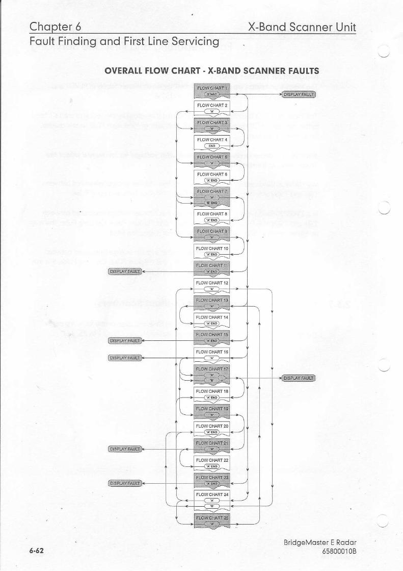
Chopter 6 X-Bond Sconner UnitFoult Finding ond First Line Servicing
OVERATI. FI.OW CHART. X.BAND SCANNER FAUI.TS
BridgeMoster E Rodor6580001085-52
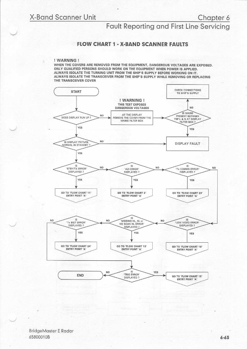
X-Bond Sconner Unit Chopter 6Foult Reporting ond First Line Servicing
FTOW CHART 1 . X.BAND SCANNER FAUI.TS
! WARNING !WHEN THE COVERS ARE BEMOVED FROM THE EOUTPMENT, DANGEROUS VOLTAGES ARE EXFOSED.ONLY OUALIFIED PERSONS SHOULD WORI( ON THE EOUIPMENT WHEN FOWER IS APPLIED.ALWAYS ISOIATE THETURNING UNIT FROM IHE SHIP'S SUPPIY BEFORE WORKING ON IT.ALWAYS ISOIATE THETRANSCEIVER FROM THE SHIP'S SUPPLY WHILE BEMOVING OR REPLACINGTHE TRANSCEIVER COVEh
---G;---l\.-------------I=
! WARNING !
DAI{GENOUS VOLTAGES
y)-/
--.e{:-""P
=l,1---
-\r/
{"i*#. ero )ii
BridgeMaster E Rodor. 658000108 5-53
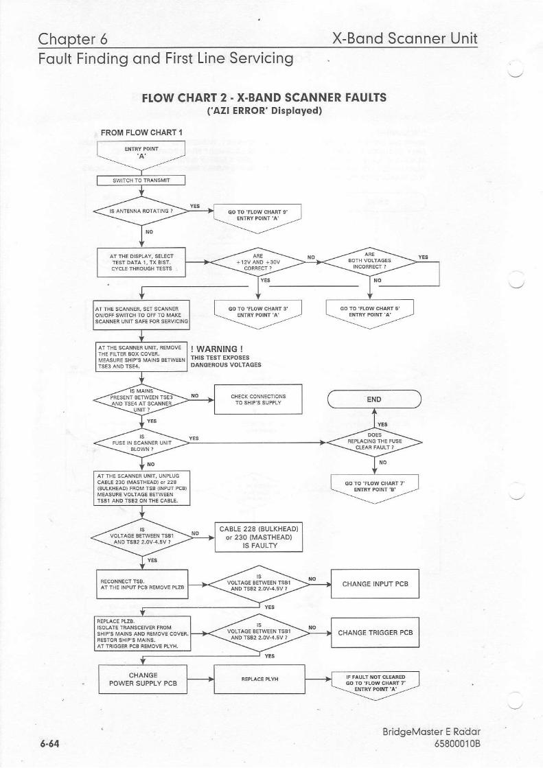
Chopter 6 X-Bond Sconner UnitFoult Finding ond First Line Servicing
FTOW CHART 2 - X.BAND SCANNER FAUI.TS('AZI ERROR' Displqyed)
! WARNING !
BridgeMoster E Roilor65800010B
FROM FLOW CHART 1
ATTHESCANNERUNtr,UNPLUG
CABLE 228 {AULKHEADIoT 230 {MASTHEAD}
6-64
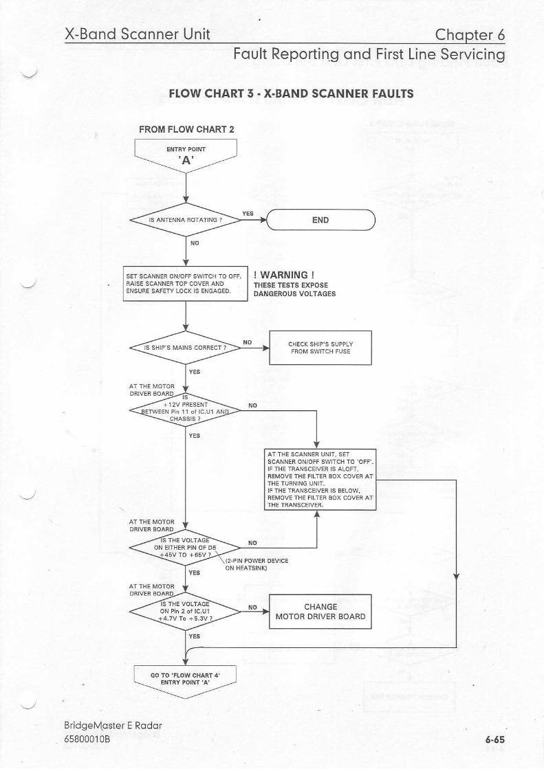
X-Bond Sconner Unit Chopter 5Foult Reporting ond First Line Servicing
FI.OW CHART 5 . X.BAND SCANNER FAUI.TS
! WARNING !THESE TESTS EXPOSEDANGEBOUS VOLTAGES
BridgeM!ster E Rodor658000108
FROM FLOW CHART 2
ser scet"en ouorr swrcr to orr,
SCANNER ON/OFf SWITCH TO'OFF'.IF lIE TRANSCEIVER IS ALOFI,iEMOVE-THE FILTER EOX COV€R AT
6.65
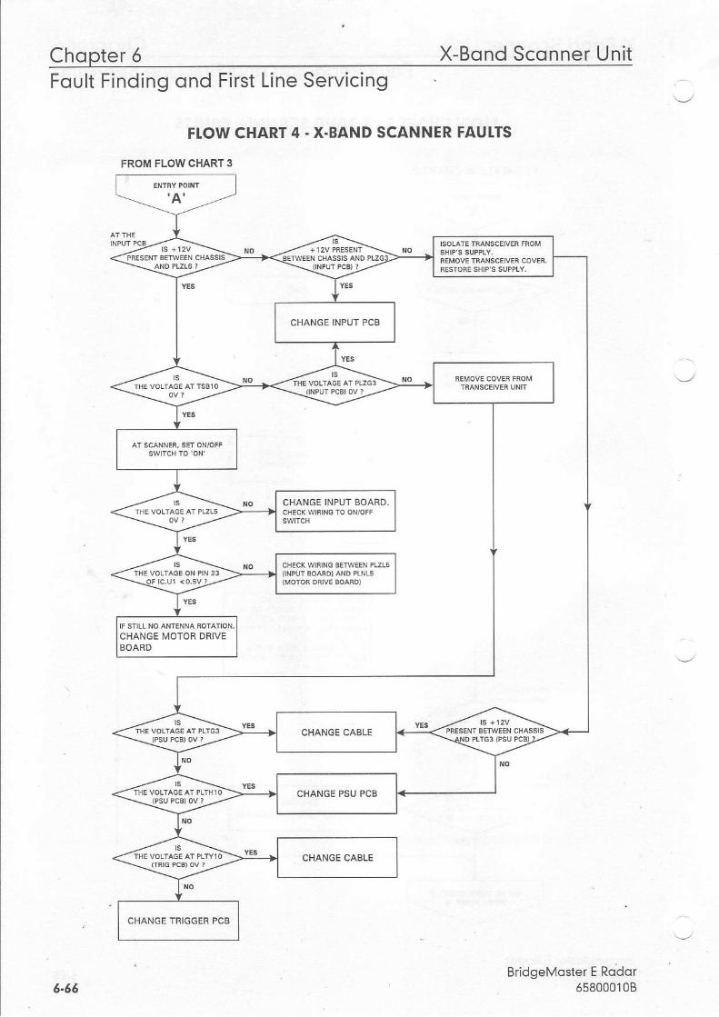
Chopter 5 X-Bond Sconner UnitFoult Finding ond First Line Servicing
FTOW CHART 4 . X.BAND SCANNER FAUI.TS
FROM FLOW CHART 3
BridgeMoster E Rodqr658000108
CHANGE INPUT BOAFD,
CHANGE MOTOF DFIVE
CHANGE TRIGGER PCB
6.66
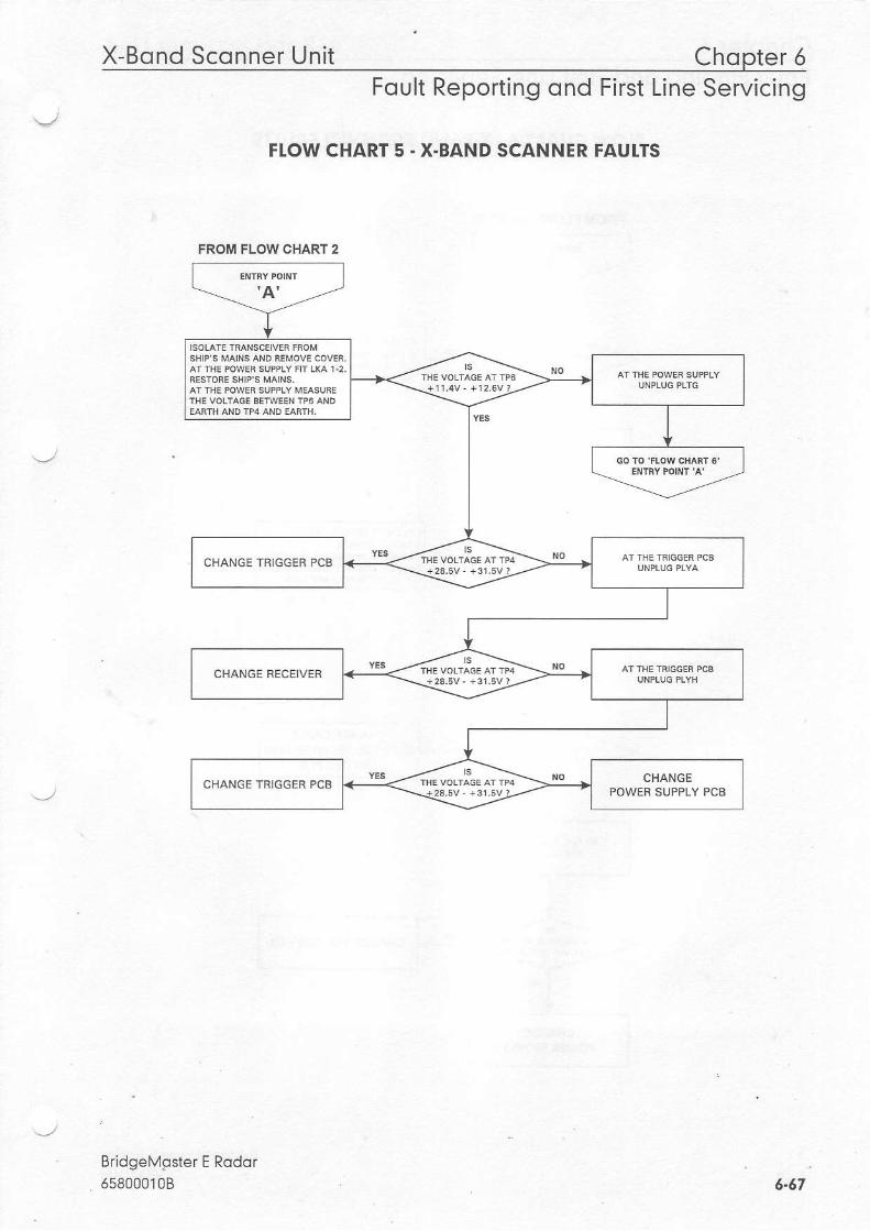
X-Bond Sconner Unit Chopter 5Foult Reporting ond First Line Servicing
FI.OW CHART 5 ' X.BAND SCANNER FAUITS
Bridgelvgster E Rodor5s8000108
FROM FLOW CHART 2
CHANGE IRIGGER PCB
CHANGE TRIGGER PCB
6.57
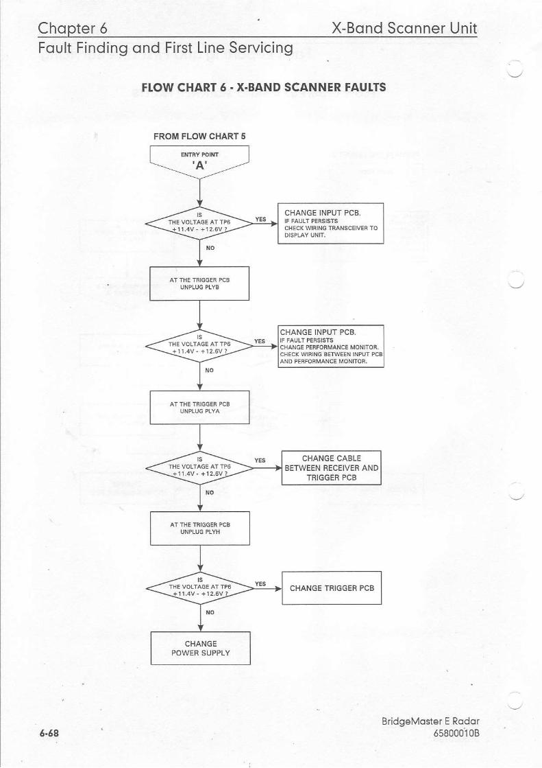
Chopter 5 X-Bond Sconner UnitFoult Finding qnd First Line Servicing
FI.OW CHART 5 . X.BAND SCANNER FAUI.TS
6.69BridgeMqster E Rodor
658oooioB
FROM FLOW CHART 5
CHANGE INPUT PCB.
CHANGE INPUT PCB.
CHANGE CABLEBETWEEN RECEIVER AND
TRIGGEB PCB
CHANGE TRIGGER PCB
CHANGE
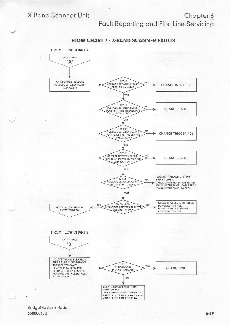
X-Bond Sconner Unit Chopter 5Foult Reporting ond First Line Servicing
FIOW CHART 7 - X.BAND SCANNER FAUI.TS
FROM FLOW CHART 2
BridgeMoster E Rodor658000108
CHANGE INPUT PCB
CHANGE TBIGGER PCB
FROM FLOW CHART 2
6.69
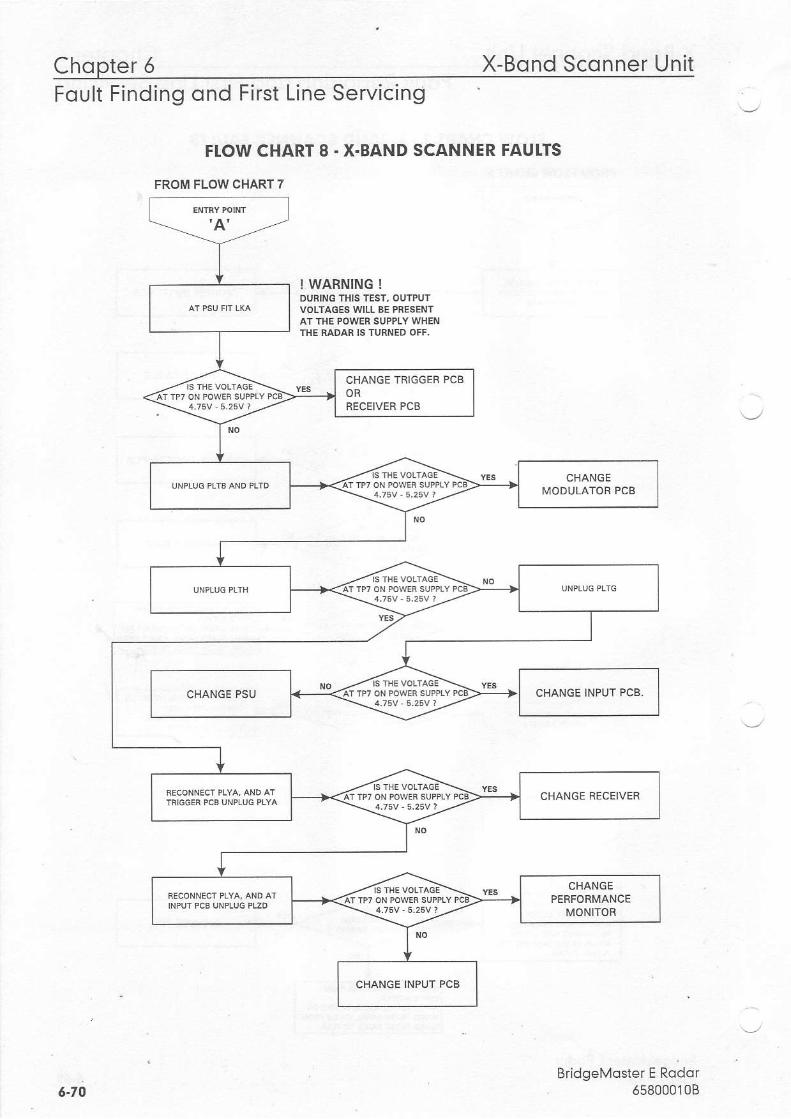
Chopter 6 X-Bond Sconner UnitFoult Finding ond First Line Servicing
FLOW CHART 8. X.BAND SCANNER FAUITS
FROM FLOW CHART 7
! WARNING !DUAING THIS TEST, OUTPUTVOLTAGES wlLL BE PRESENTAT TI.IE POWER SUPPLY WHE'\III.IE MDAR IS TURI{ED OFF,
CHANGE INPUT PCB.
BridgeMoster E Rodor658000108
CHANGE[,IODULATOR PCB
CHANGE RECEIVER
6-70
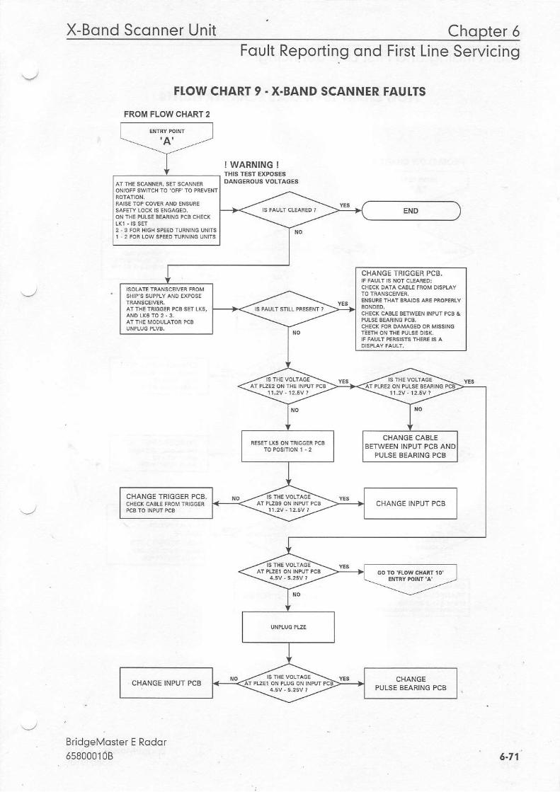
X-Bond Sconner Unit Chopter 6Foult Reporting ond First Line Servicing
FI.OW CHART 9 - X.BAND SCANNER FAUI.TS
FROM FLOW CHART 2
I WARNING !
BridgeMoster E Rodor558ooo10B
CHANGE TRIGGER PCB.
CHANGE CABLEBETWEEN INPUT PCB AN
PULSE BEAFING PCB
CHANGE TBIGGER PCB.CHANGE INPUT PCB
CHANGEPULSE BEARING PCB
6.71
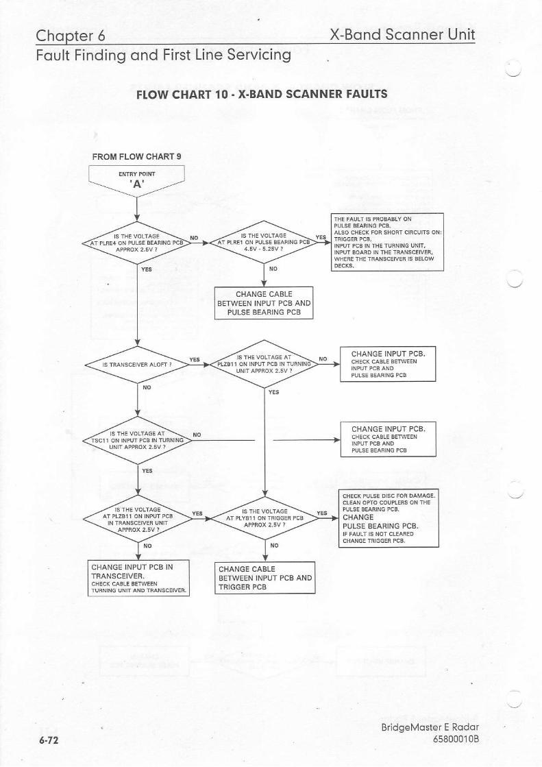
Chopter 5 X-Bond Sconner UnitFoult Finding ond First Line Servicing
FI.OW CHART 10 . X.BAND SCANNER FAUI.TS
BridgeMoster E Rodor658000',l08
FROM FLOW CHART 9
NPUrrc8|NTHEIIJRN|NGUN|T,
CHANGE CABLEBETWEEN INPIJT PCB AND
PUISE BEARING PCB
CHANGE INPUT PCB,
CHANGEPULSE BEARING PCB.
CHANGE INPUT PCB INTRANSCEIVER.
CHANGE CABLEBEIWEEN INPUT PCB ANDTRIGGER PCB
5.72
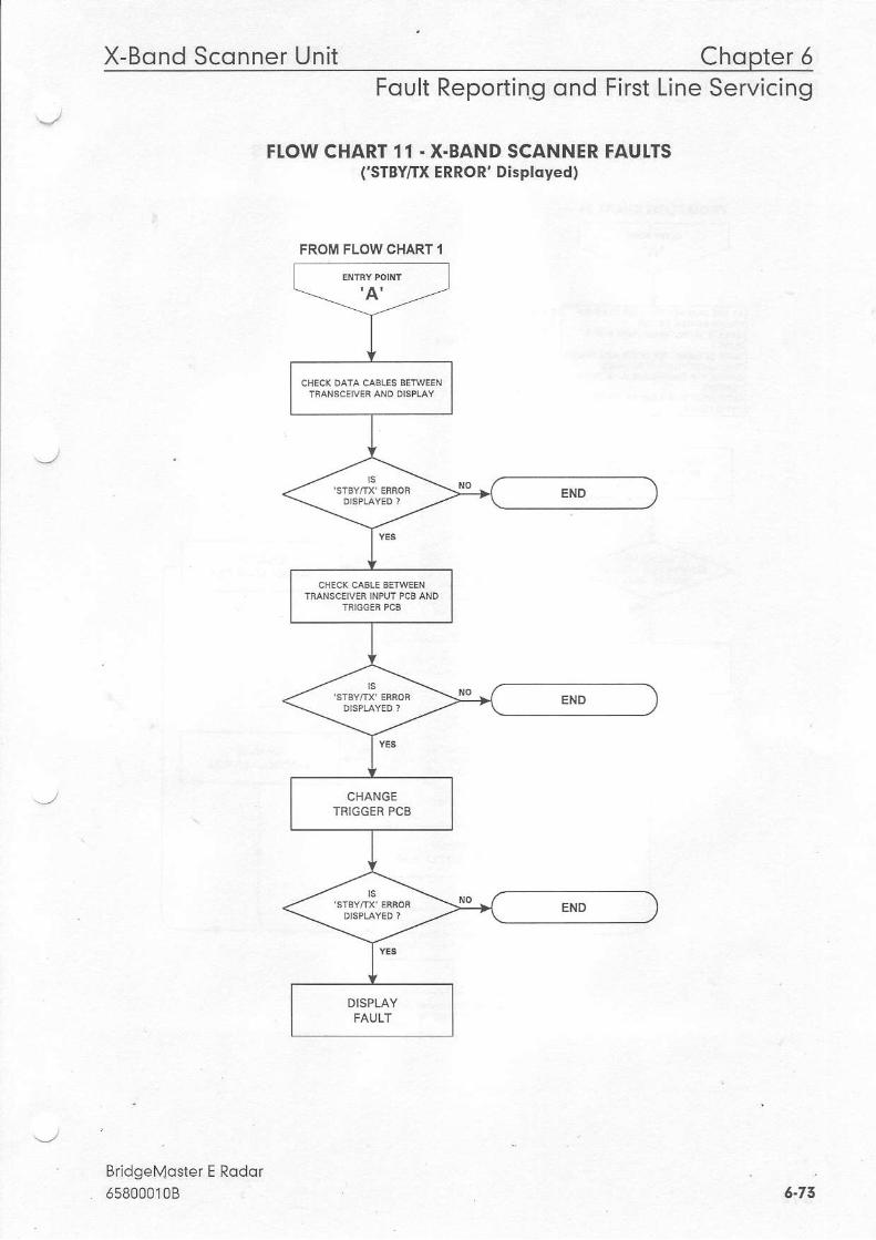
X-Bond Sconner Unit Chopter 5Foult Reporting ond First Line Servicing
FI.OW CHART 11 - X-BAND SCANNER FAUI.TS('SrBY/IX ERROR' Displqyedl
BridgeN4oster E Rodor658000108 6.73
FROM FLOW CHART I
CHANGETRIGGEA PCB
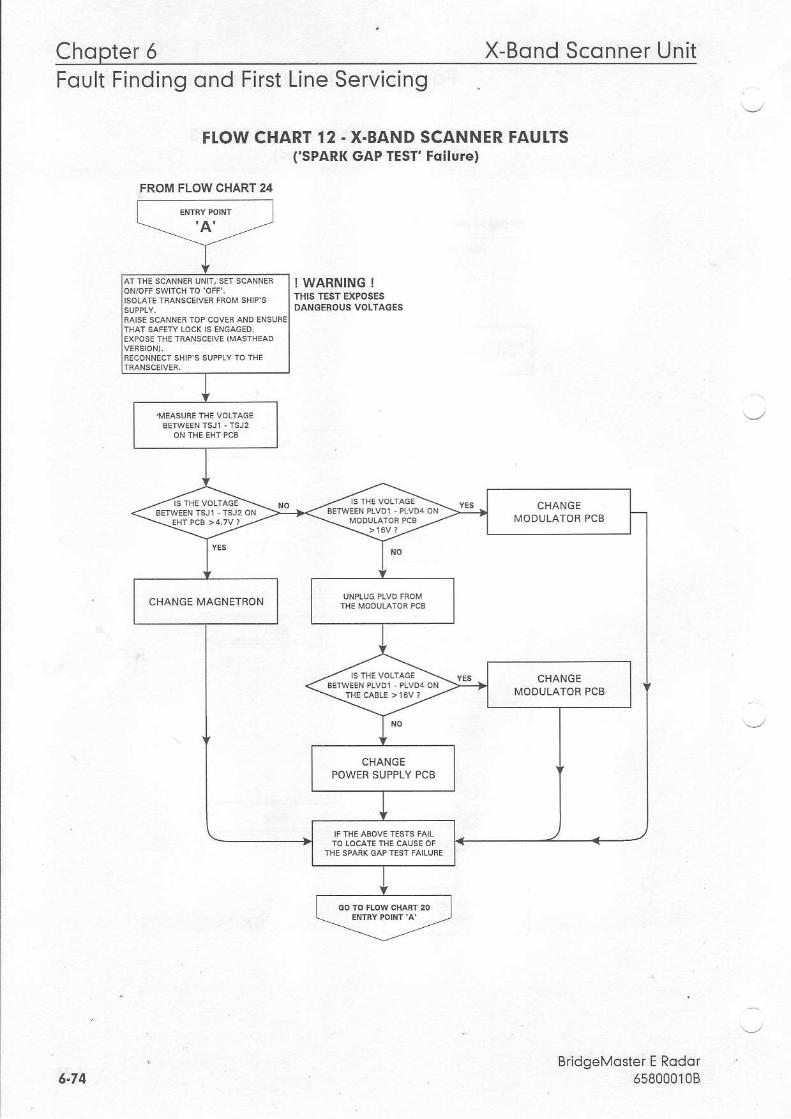
Chopter 6 X-Bond Sconner UnitFOUtt Frnorno ono Ftrsl Ltne bervtctnq
FIOW CHART 12 . X.BAND SCANNER FAUI.TS('SPARK GAP TEST' Follure)
I WARNING !THIS TEST EXPOSESDANGEROUS VOTIAGES
BridgeMoster E Rodqr658000'108
FROM FLOW CHART 24
INESCANNERUN|T,sErsdNNEh
CHANGE
CHANGE MAGNETRON
CHANGE
6.74
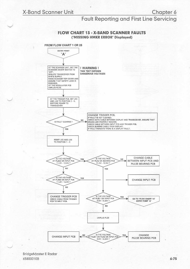
X-Bond Sconner Unit Chopter 5Foult Reporting ond First Line Servicing
FI,OW CHART 15 - X.BAND SCANNER FAUTTSfMISSING HMKR ERROR' Displdyed)
FROM FLOW CHART I OR 25
! WARNING !
Br;dgel\4oster E Roddr558000'l0B
CHANGE TRIGGER PCB.
CHANGE CABLEBETWEEN INFUT PCB AND
PULSE BEARING PCB
CHANGE iBIGGER PCB
CHANGE
5-75
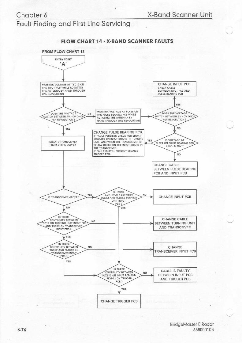
Chopter 6 X-Bond Sconner UnitFoult Finding ond First Line Servicing
FIOW CHART I4. X.BAND SCANNER FAUI.TS
FROM FLOWCHART 13
BridgeMoster E Rqdor658000108
CHANGE INPUT PCB.
CHANGE PULSE AEANING PCB.
CHANGE CABLEBETWEEN PULSE BEAR]NGPCB AND INPUT PCB
CHANGE INPUT PCB
CABIE IS FAULryBETWEEN INPUT PCBAND TRIGGER PCB
CHANGE TRIGGER PCB
6-76
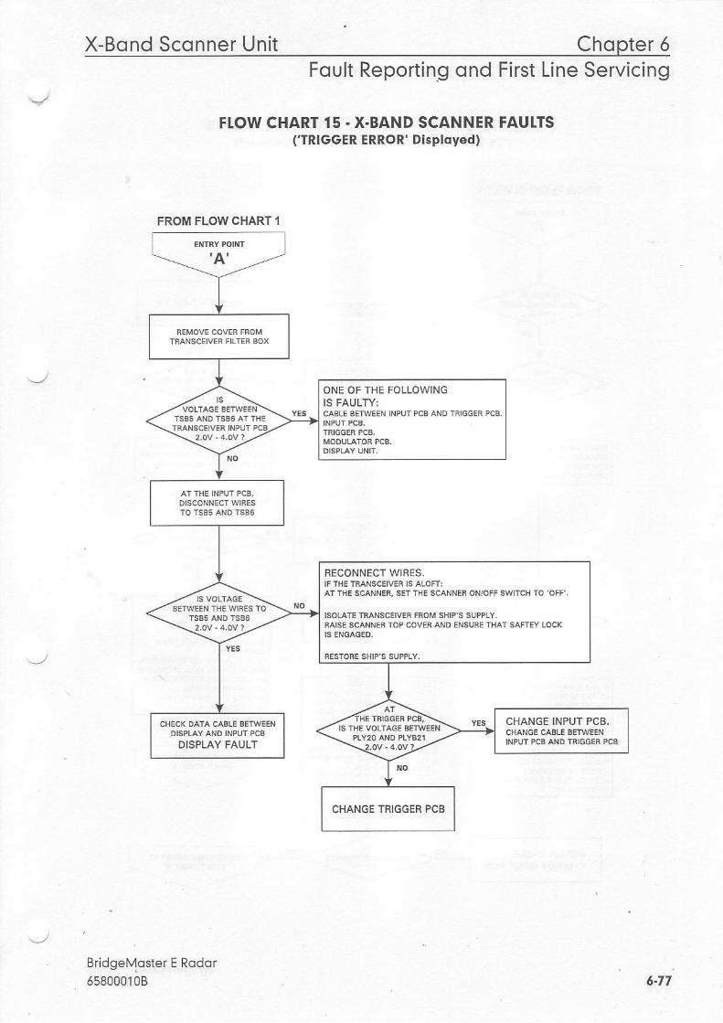
X-Bond Sconner Unit Chopter 5Foult Reporting ond First Line Servicing
FTOW CHART 15 . X.BAND SCANNER FAUI.TS('TRIGGER ERROR' Displqyed)
BridgeMoster65800010B
FROM FLOW CHART I
ONE OF THE FOLLOWINGIS FAULTY:CAELE AEIWEEN INPUT PCS AND TRIGGER PCB.
RECONNECT WIRES.
RAISL SCAXNL N IOP COVFfi AND
IS IHE VOLTACE BFTWEENCHANGE INPUT PCB.C(ANGE CAELE BETWEENDISPLAY AND INPUT PCE
DISPLAY FAULT
CHANGE TRIGGER PCB
6.f7
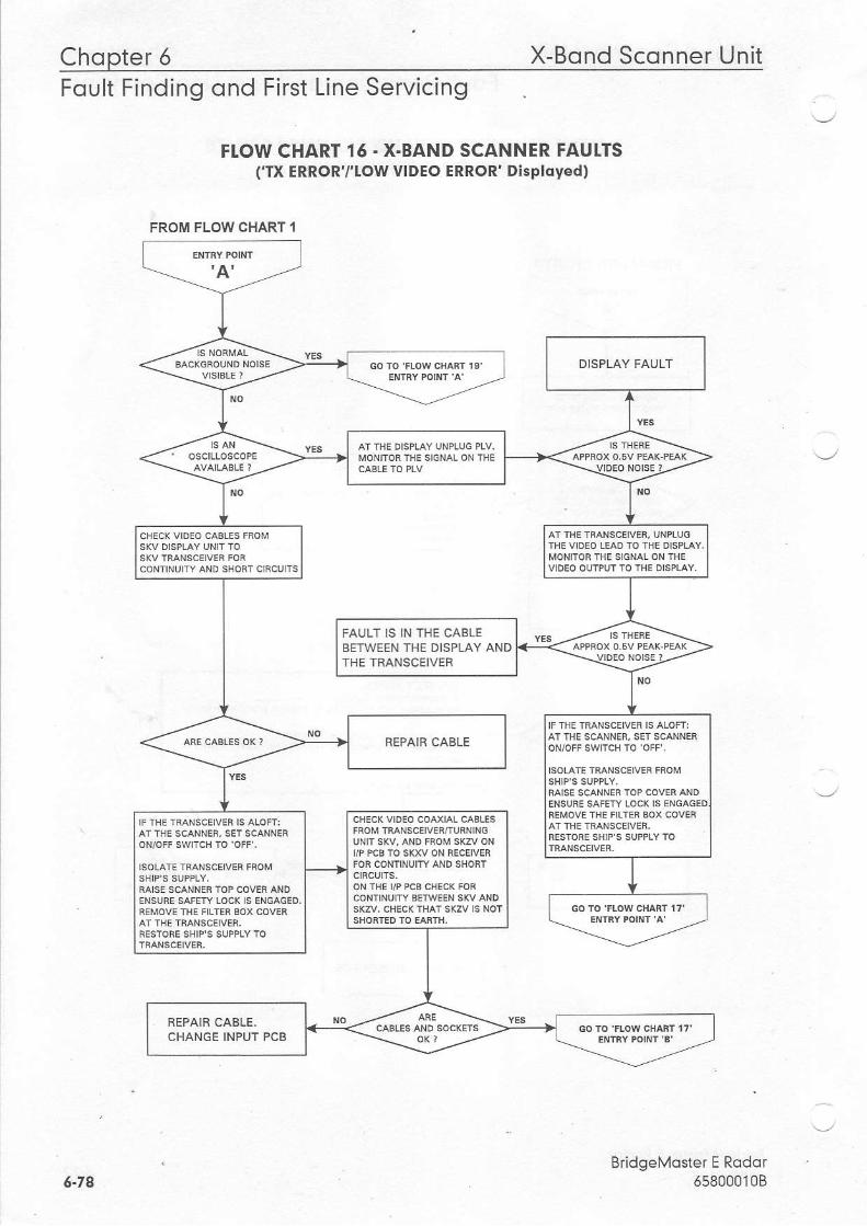
Chopter 6 X-Bond UnitSco n nerFoult Finding ond First Line Servicing
FI.OW CHART 16 - X-BAND SCANNER FAUTTS(Tx ERRORT'Low vlDEo ERRoR' Dlsployed)
BridgeMoster E Rodor658000108
FROM FLOW CHART I
FAULT IS IN THE CABLEBETWEEN THE DISPLAY ANDTHE TRANSCEIVEB
/P PCB TO SXXV ON RECEIVER
REPAIR CABLE.CHANGE INPUT PCB
6-74
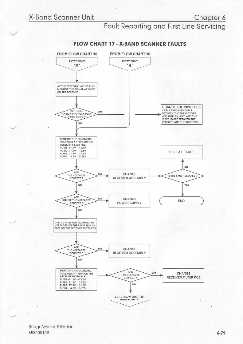
X-Bond Sconner Unit Chopter 5
FTOW CHART
FROM FLOW CHART '16
Foult Reporting ond First Line Servicing
17 - X-BAND SCANNER FAUITS
FROM FLOWCHART,16
BridgeMqster E Rodor658000108 6-79
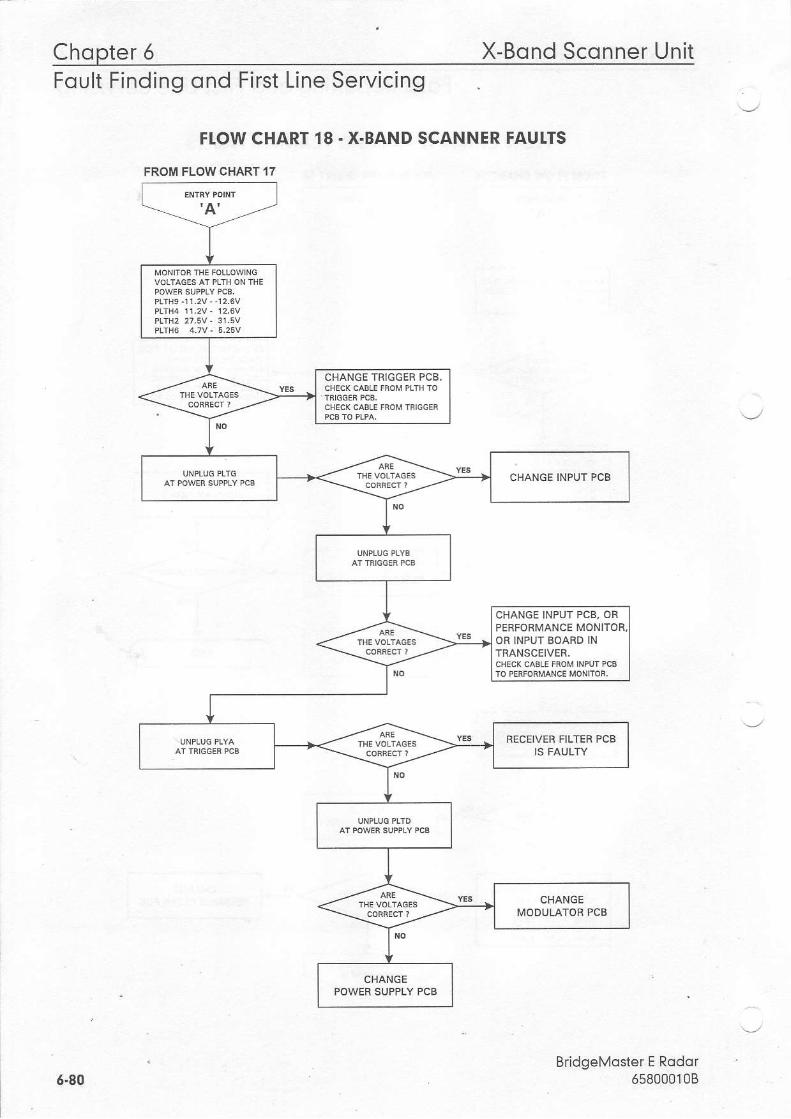
Chopter 5 X-Bond Scqnner UnitFoult Finding ond First Line Servicing
FI.OW CHART 18 - X-BAND SCANNER FAUITS
FROM FLOW CHART 17
Bridgelvoster E Rodor658000108
CHANGE TRIGGEF PCB.
CHANGE INPIJT PCB, ORPERFORMANCE MONOB TNPUT BOARD INTRANSCEIVER.
RECEIVEF FILTER PCB
6.80
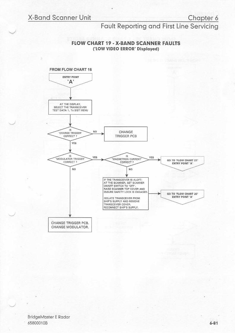
X-Bond Sconner Unit Chopter 5Foult Reporting ond First Line Servicing
FI.OW CHART 19 . X.BAND SCANNER FAUTTSf IOW VIDEO ERROR' Disployed)
BridgeMbster E Rodor658000108
FROM FLOW CHART I 6
CHANGETBIGGER PCB
CHANGE TAIGGER PCB.CHANGE MODULATOR.
6.41
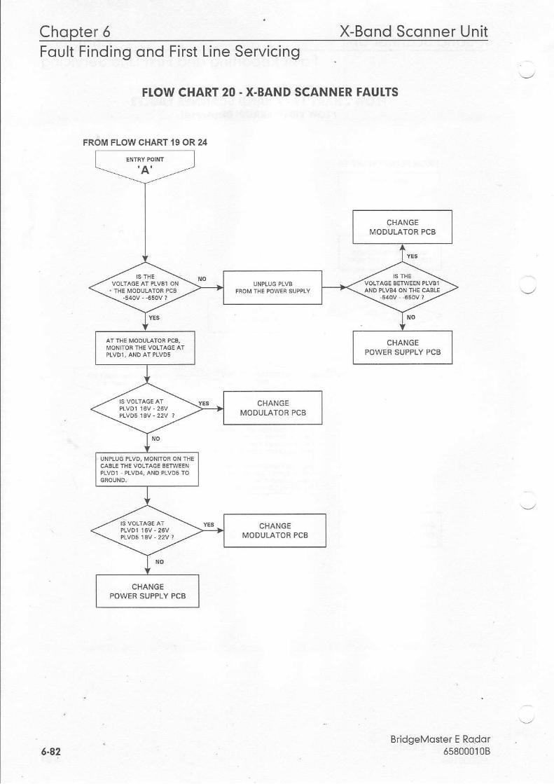
Chopter 6 X-Bond Sconner UnitFoult Finding ond First Line Servicing
FI.OW CHART 20 - X-BAND SCANNER FAUI.TS
6"e2BddgeMoster E Rodor
65800010B
FROM FLOW CHART 19 OR 24
CHANGEPOWER SUPPLY PCB
CHANGEIlIODUIATOB PCB
CHANGEPOWER SUPPLY PCB
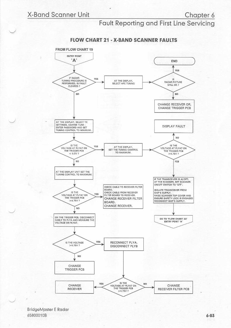
X-Bond Sconner Unit Chopter 6Foult Reporting ond First Line Servicing
FTOW CHART 21 . X.BAND SCANNER FAUTTS
FROM FLOWCHART19
BridgeMgster E Rqdor658000108
CHANGE RECEIVER OF,CIIANGE TRIGGEF PCB
CHANGE RECEIVER FILTERBOARD.CHANGE RECEIVER,
DISCONNECT PLYB
CHANGEFECEIVER FILTER PCB
6.43
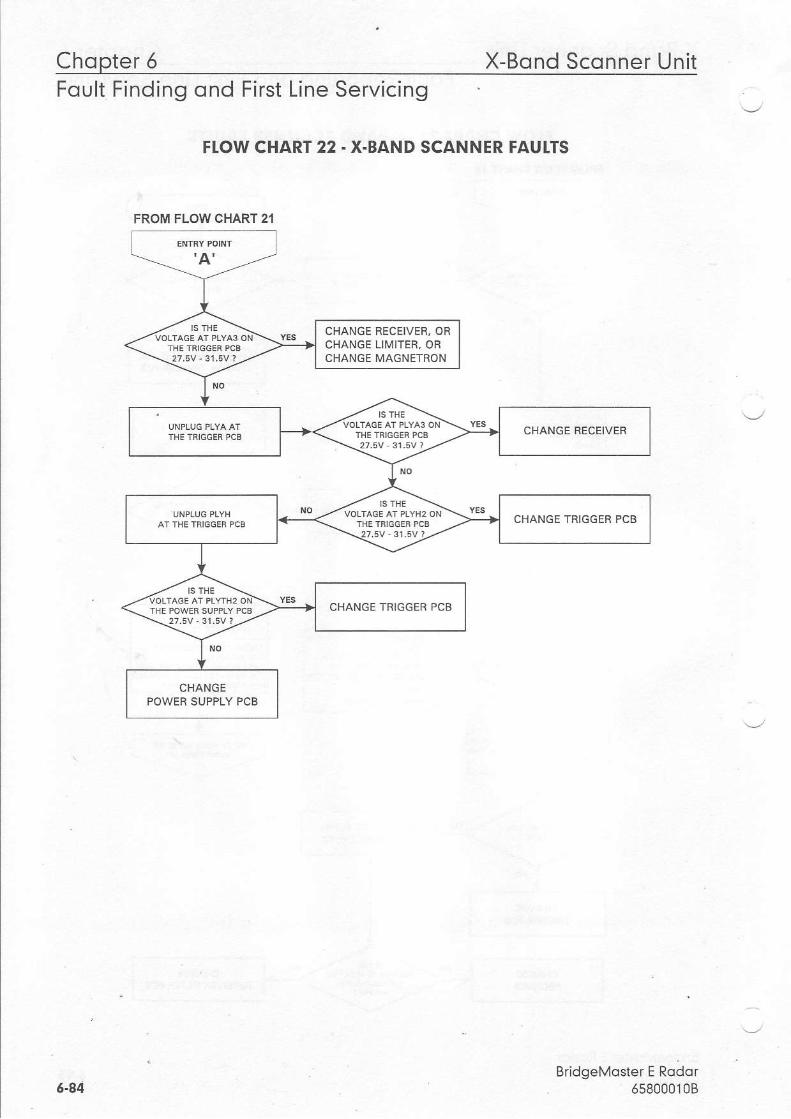
Chopter 6 X-Bond Sconner UnitFoult Findinq ond First Line Servicino
FI,OW CHART 22 . X.BAND SCANNER FAUI.TS
BridgeMoster E Rodor65800010B
FROM FLOW CHART 21
CHANGE BECEIVER, ORCHANGE LIIVIITER, OBCHANGE IVIAGNETRON
CHANGE RECEIVER
CHANGE TRIGGER PCB
CHANGE TRIGGEN PCB
CHANGEPOWER SUPPLY PCB
G-84
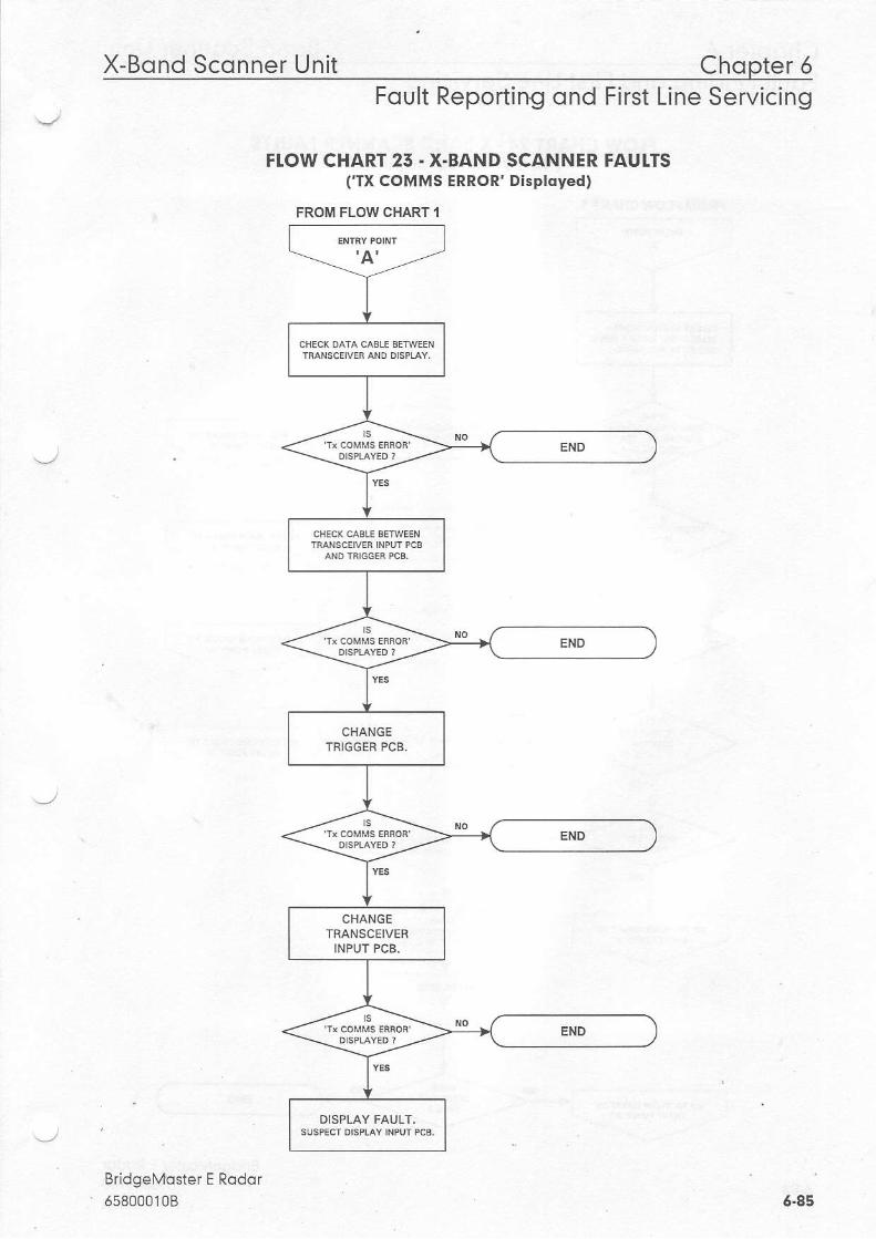
Chopter 5X-Bond Sconner Unit
FROM FLOW CHART 1
CHANGETFIGGER PCB.
CHANGETRANSCEIVER
INPUT PCB.
Foult Reporting ond First Line Servicing
FI.OW CHART 25. X.BAND SCANNER FAUI.TS(TX COMMS ERROR' Disployed)
BridgeMoster E Rodor65800010B 6-85
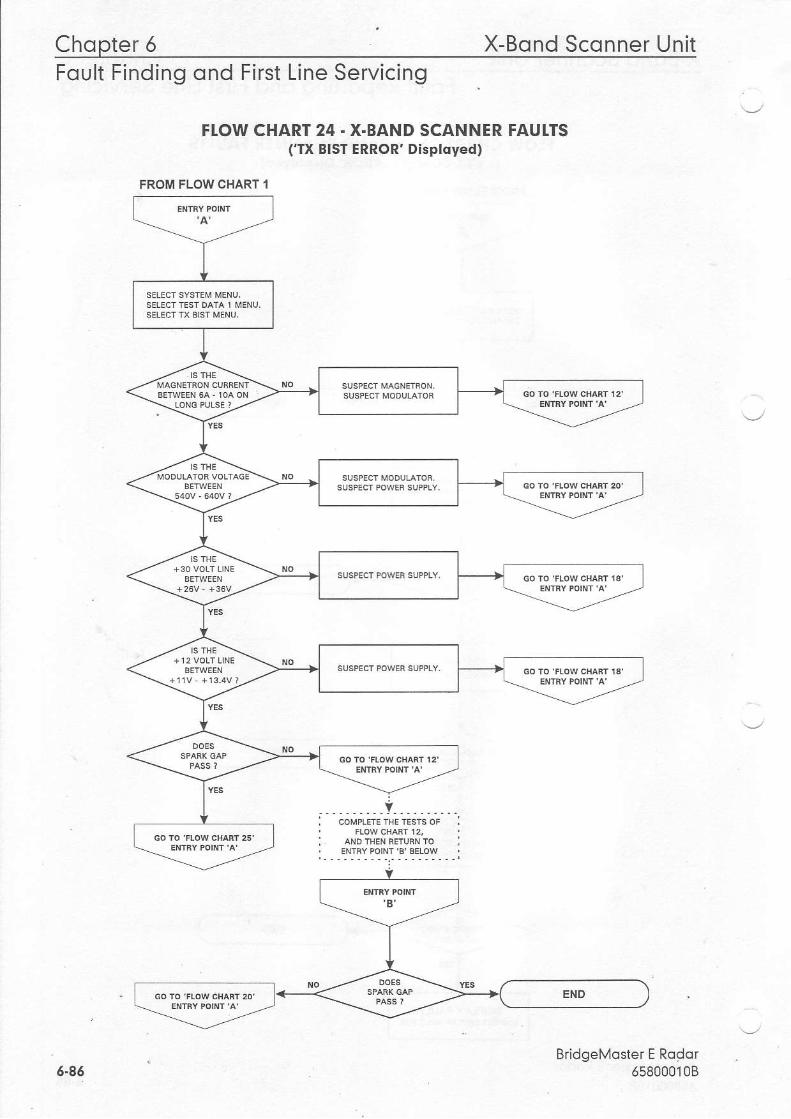
Chopter 5 X-Bond Sconner UnitFoult Finding ond First Line Servicing
FI.OW CHART 24 . X.BAND SCANNER FAUI.TS('TX BIST ERROR' Disployed)
v
6.86BridgeMoster E RqCdr
658000108
FROM FLOW CHART I
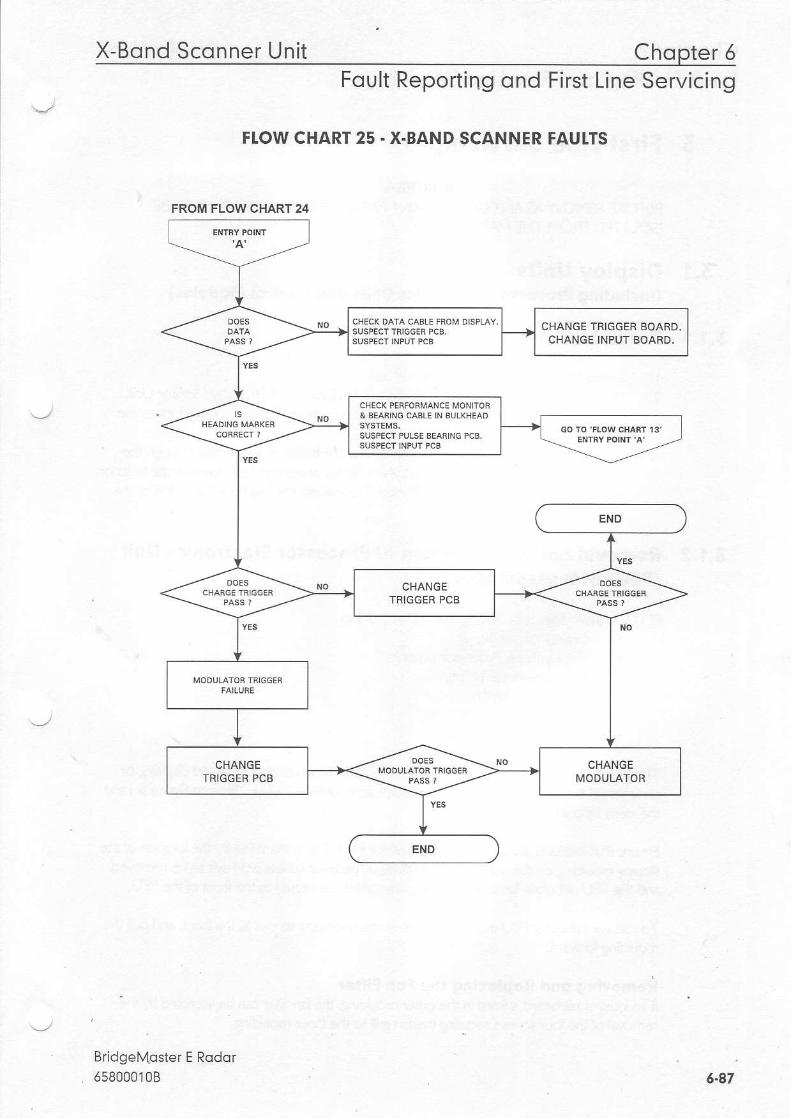
X-Bond Sconner Unit Chqpter 5Foult Reporting ond First Line Servicing
FI.OW CHART 25 - X-BAND SCANNER FAUI.TS
Bridgel\,toster E Rodor658000'l0B
FROI/| FLOW CHART 24
CHANGE TR!GGER BOARD.CHANGE INPUT BOARD.
6-47

Chopter 5 Disploy UnitFoult Finding ond First Line Servicing
5 First Line Servicing
WARNING:BEFORE REI4OV NG ANY COI,IPONENT PARTS, THE EQUIPMENT I"1U5T BEISOLATED FROIY TIE IYAINS SUPPLY,
5.1 Disploy Uni ts(lncluding Processor Electronics Unils ond Control Modules)
5.1.1 Prel iminory Notes
L lsolate the mains supplyto the dispay unit.2. Before disassembling the Processor Electronics Unit or CRT Display f'lonitor Unit
'componentsoftheDisplayUnit,ensurethattheintegrit/ofthe connections to theunits has been checked.
3 . A I radar use r controls, except for dis play monltor brilliance are routed through theDisplay Processor board. Consequently, a display processorfaut may indicate faults onthe Display Processor board, the Joystick/Trackerball, the Memory Card Unit ortheKeyboard.
5.1,2 Removol ond Replocement of Processor Electronics Unit(PEU) Sub-ossemblies
Dl U s. b asserol es na/ nclude rhe folov'i-g unils:. Display Power Supply. D splay/Radar Processor board(s). Integral Keyboard (optional). IntegralJoystick/Trackerball. Integra Memory Card Unit. On/Off Switch assembly
The Processor Electronics Unit is located in the pedestal ofconsole mounted dlsplays, orunderneath the display monitors of integral (desk mounted) displays. Refer to Figure 6.landll-F Jc1( \cl^w ;1r r.rF(c ln .rese Lnils.
Ensure that access is available to the front ofthe PEU. This is identilled by the location ofthesloping moulding on the unit. In console displays, pedestal covers will have to be removedand the PEU unbolted for access. Unplug any cables connected to the front ofthe PEU.
To release the outer PEU rnoulding, remove the lMo fixlng screws atthe front, and pull themoulding forward.
Removing ond Replqcing the Fdn Filter- l fan in tegra lkeyboard is i t ted ln theoutermou ld ing , the fan f l te rcanbeaccessedbythe
' removal ofthe four screws securing the fan gdllto the_inner moulding.
. BridgeMoster E Rodof6.88 6s800010B

Disploy Unit Chopter 6Foult Reporting ond First Line Servicing
lf no keyboard is itted in the outer moulding, the fan lliter is located in the rectangu Lar lilterrecess at the front ofthe inner rnoulding. lt is removable once the outer moulding has beenTeleased.
Removing ond Replocing the Integrdl Keyboord (optionol)The integral Keyboard can be removed and replaced at this stage. Be sure to re connect itscaDte,
fthe outer moulding contains a keyboard, disconnecr its cable where it plugs into the innermoulding. Remove the fourfixing screws securing the inner mouldingto the PEU main body,and pull the moulding away from the body. Disconnect a I cables to units in the innermoulding at the processor boards and power supply in the main body ofthe PEU.
Removing ond Replocing lhe Integrol On/Oll Switch ossemblyThe switch flxing plale can be removed from the inner moulding using a small lY3 spanner,and the switch assembly pushed out ofthe {lxing plate. Reverse the procedure forreplacement.
Removing ond Replqcing Integrol loystick/Trqckerboll ond MemoryCqrd qssembliesfa memory card assembly is it1ed, disconnect the cable linking itto the joystick,trackerballassembly. Loosen the locat ng screw forthe appropriate assembly - see Figure 6. L Pulltherequired assembly out from its moulding apedure by pivoting it on the lower edge oftheaperture, and then lifting up. Reverse the procedure for replacement.
Removing ond Replocing lhe Power SupplyDisconnect the power cable at the front ofthe power supply. The power supp y can then beremoved by pul ing on the strap at the front ofthe power supply cover, and sliding the unitour.
Slide the replacement unit back in, ensudng that it is firmly pressed home. ReconnecttheooweT caDie,
Removing ond Replocing the Processor Boqrd(s)In displays with a sing e Combined Processor board, replace this board if either radarprocessor or dispay processorfaults are suspected.
In displays with separate Radar and Display Processor boards, identiq, the board to bereplaced. The display processor has more connectors on its edge than the radar processor.Remove any cables still connected to the board. Use the plastic ejection levers at each end ofthe board to ever out, and then puJl out the board.
Remove a1l daughter boards from the processor board, and transferthem to thereplacement board, ensuring correcl orlentation and location. Ensure that links on therep r(eme-L bodrd are seT app-opriately.
BridgeMoster E Rodor658000108 6-e9

Chopter 5 Disploy UnitFoult Finding ond First Line Servicing
Replace the board ensuring thatthe ejection levers are in their home position when theboard is plugged in. Ensure thatthe board is firmly pressed home. Reconnect any cables, ifappropnate, to omer processor ooaTQs.
Removing ond Replocing the Composs BoordThe Compass board is a daughter board on the Display Processor board or CombinedProcessor board. Use the above procedure for replacingthe processor board(s) inthis case,but only replace the compass board, with one ofthe same type. Ensure that the links on thereplarorrenl board dre sel apProp'ialely.
Re-cssembling lhe Processor Electronlcs UnitReconnect cables from front PEU moulding, and re secure the mouldings, remembering tore-connect the Keyboard, ifappropriate. Refer to Figure 5.7 in case ofdifflculty.
5.1.5 Removql ond Replocement of Kit Control Ponel Modules --,
Kit Control Panel modules may include the folowing modulesr. Keyboard module (optional). loystickfrackerballmodule. lYemory Card modu e. On/Of Switch module. Brilliance module
Each module js secured by nuts from underneath the control panel top suface. Unplugconnecting cables to the modules before removing them. Refer to Figure 3. 100 in Chapter 3when re connecting cables.
5.1.4 Removol ond Replocement of Operotor Controls on540 Disploy Units
For versions wrth extruded control panel (as shown ln Figure 6.2 in this chapter), removecontrol Danel lower cover, and then Droceed as in sub section 3.1.3.
For versions with moulded control panel (as shown in the Preamble at front of manual), thecontrol panel must be hinged down by releasingthe two securing screws hidden behtnd theslotted covers on the underside ofthe control panel. This will expose the locating screws forthe Trackerball,{oystick and ]'4emorycard assemblles atthe back ofthe unit. Loosen theLocating screws forthe appropriate assembly, and remove the assembly by pivoting itupwards on the front edge ofthe moulding aperture. Unplug the interconnecting cablesbefore fully removing the assemblyfrom the apedure.
Reverse the Drocedure for reDlacement.
BridgeMoster E Rodor65800010B6.t0

Disploy Unit Chopter 6Foult Reporting ond First Line Servicing
5.1.5 Removql of CRT Disploy Monitor unit Sub-ossemblies
Desk Mounted 180 ond 250 Disploy MonitorsRemove monltor outer cover by unscrewing the two screws on tfe top ofthe cover, liftlngthe cover up and then forward, and unplugging the brilliance controlcable atthe Brillianceboard (mounted on the bezel moulding), The Brilllance board can be removed, if necessary,by unscrewing it from the bezel moulding.
Unplug all cables connected to the monltor, taking note ofthe location ofthe SecondaryViewer cable, if fitted.
Unscrew the four screws at the edge ofthe {lnned drive board heatslnk, that secure it to thechassis, and hinge it away from the chassis. Using the appropriate monitor block diagram forthe particular monrtor display (1ig!res 6.3 to 6.6), identit the nionitor components containedwithin the dotted outline in the diagram. These must be replaced as a group. Leavingthedrlve board until last, and first having ensured that at least 3 minutes has elapsed from swrtch-offforthe CRT anode voltage to safely discharge, disconnectthe identified interconnectedcomponents frorn the rest ofthe unjt. The drive board assemb y (this includes the llnnedheatsink) can be removed by unscrewing the hinge arms and board stay from the unit.
540 Disploy Monilors ond 180,250 ond 540 Kit Monitor ModulesTo gain access to the display monitor in the 340 deck-mounted display unit, refer to Figure6.2. Ensure thatthe display unit is securely assembled and deck mounted. Whilst supportingthe consoie control panel, re ease its two captive llxing screws, and then let it swing down. ltmay be necessary to remove the control panel lower coverto access these llxing screws.Release the two captive monitorilxing bolts underthe monitor. They are accessible frombetween the control panel and display monitor. Remove the display top handle by undoingits three fixing screws. Undo the four CRT bezel fixings, and gulde the top ofthe monitorfonrard into the unit's service posrtion.
Unplug all cables connected to the monitor, taking note ofthe location of the SecondaryViewer cable, if fitted.
Release the two latch levers securing the llnned drive board healsinkto the chassis, andhinge it away from the chassis. Using the appropriate monitor block diagram forthe particuLarmonitor display (Figures 6.3 to 6.6), identify the rnonrtor components contained within thedotted oLrt ine in the diagram. These must be replaced as a group. Leavingthe drlve boarduntil last, and first having ensured that at least 3 minutes has elapsed since swltch-offfortheCRT anode voltage to safely discharge, disconnect the jdentified interconnected componentsfrom the rest ofthe unit as a group. The drive board (this includes the finned heatsink) canbe removed by detaching the earth braid connection to the chassis atthe drive board,releasingthe board stay, and sliding the drive board hinges apad.
BridgeMoster E Rodor658000108 5.91

Chopter 6 Disploy UnitFoult Finding ond First Line Servicing
3.1.6 Replocing ond Sett ing-up ol CRT Disploy Monitor UnitSub-qssemblies
Replace the boards using the appropriate board set as shown in Section 4. I of this chapter.To fit the board sets, use the reverse ofthe removal procedure. After reconnecting theexternal monitor cables, connectthe internal brilliance control up (ifapplicable), and leavethe drive board in its hinged down position to facilitate adjustments duringthe setting upprocedure below.
Note : lfan RGB output board is frtted to the dive board that b beng replaced, thbmust be transferred to the drive board in the rep/acement board set. lt tssecured b/ two screv/s on the drive board healsink, and lts rlbban cable plugsn'a the dr^ e board.
Aflei checklng that the display boards are fully reconnected, power Lrp the radar display, andcheckthatthefan (iffitted) is operating. Refer to 'Monitor Test Mode'section in Chapter 5for the followlng adjustmentsl
Adjust the brillance control to a norrnal ievel. Access the monitor test rnode, and seLect TestPattern l.
ldentit the location of the focus and screen (Grid 2) controls. lf they are not situated on the. LOPT they wil be found on the adjoining dualfocus module.
Adjust the focus control(s) forthe sharpest whlte grld lines.
GeometryUsingthe lYonltor Test menu on the screen, adjust (if necessary) the geometrical pararnetersin the left hand column ofthe rnenu to produce the closest match to Test Pattern I asshown in the manual. lf necessary, adjust the horizontal linearity inductor L I to match thewidth ofthe left hand squares to the other squares. Adjust the pattern size to fill the screenwith its white borderfully visible.
Colour Level AdiustmentThis must be carried out underthe minimum operating ambient light level conditionsSelect Test Pattern 2, and adjustthe display brilliance controlto maximum.Adiust the presetbrightness parameter (lYonitor Test menu) so thatthe pattern is just visible.
Select Test Pattern 3 with a solid white rectangle displayed. Ad.just the display brllliancecontrol, black level (red) and black level (blue) so that the white rectangle is just visible and agood white.
Adjustthe display brilliance, and red and blue gain controls to give the brightest picture'withoutanysignsofvideooverload(streaking),andawhiterectanglewithahintofblue lf
' necessary, the green gain can also be adjusted.
BridgeMoster E Rodor6580001086-92

Disploy Unit Chopter 6Foult Reporting ond First Line Servicing
Repeatthe colour level adjustment procedure until no fudher adjustrnents are required.
lf any problems are encountered regarding insufiicient control range on any ofthe controls,adjustthe screen (G2) control on the drive board as follows:
Using a DVM, measure the voltages on TP26, 27 and 28 on the drive board (on externalconnectors edge of board) with respect to the chassis. Adjust the screen control so thatthethree voltages measured are in the range 65 to 95V. The colour level adjustment proceduremustthen be carried oul once more.
As afinal step, setthe display brilliance to maximum, and adjust the preset contrast controltogive the brightest picture withoutvideo overload.
Switch off and complete the re-assembly ofthe display monitor, lfthe picture size wasadju(ed withoLrt the CRT bezel itted, re-adju( the picture size so that the whhe border ofTest Pattern I is fully visible.
BridgeMoster E Rodor55800010B 6'93
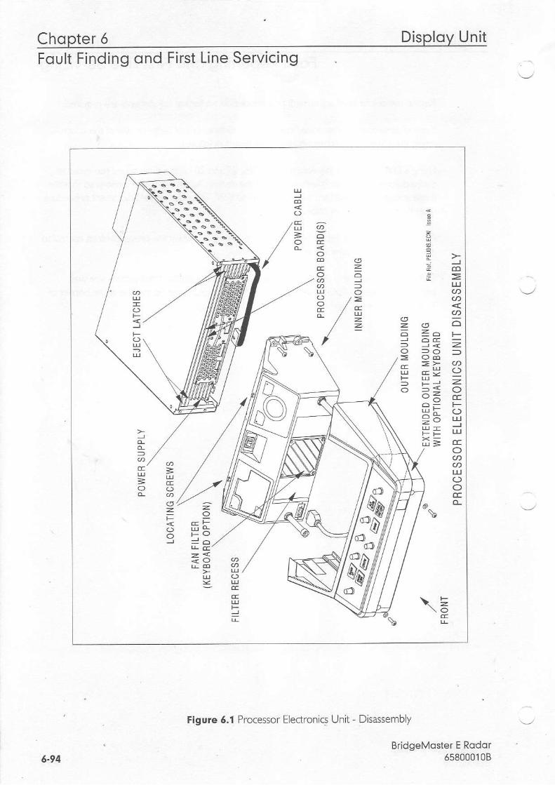
Chopter 6 DisPloY UnitFoult Finding ond First Line Servicing
Flgure 6.1 Processor Electronics Unit - Disassembly
BridgeMoste. E Rodof558000108
U 5
i =
\ =
lL
t2 />
=
2o
=z,=
::z
E
<->L!
ccO
UI(_)OCEo_
=
=
tr =
=
I
=
=
llY,sell
5-94
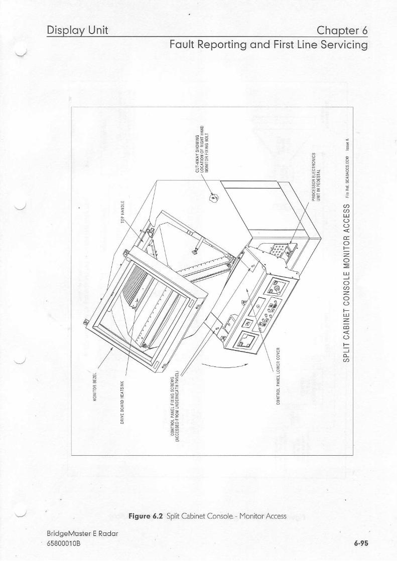
Disploy Unit Chqpter 6Foult Reporting ond First Line Servicing
BridgeMostef E Rodor65800010B
Figure 6.2 Split Cabinet Console.- lYonitor Access
6-95
t 9 ;p
EoLz
oza
F
zco
io-
9,2
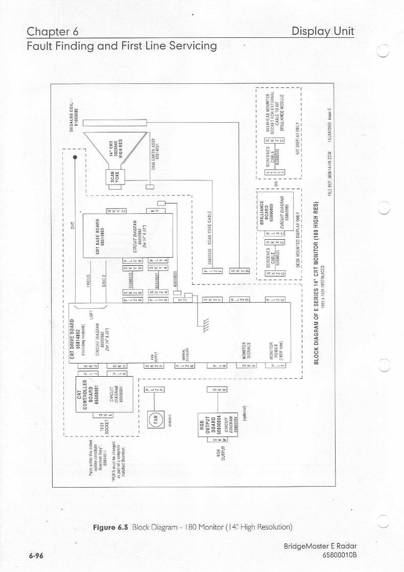
Chqpter 6 Disploy UnitFoult Finding ond First Line Servicing
tigure 6.5 Block Diagram - 180]'4onitor (141 High Resolution)
BridgeMoster E Roaor658000108
€ = s I
; 3 H = i
; 3 5 6 l
t;=i;t dl
E<IE
- - ; - - - - -
3 a
a ;
ffiiE;u= g:.,= -q-: B 3:;; - " i a *
; E
=i
a r
l
I i - = lt - f l
I ? F E € P I: I i 1 E : < ,
3 ; ; E - 5 ,: 1 . :
{L r*r i_t -T-- :E l L , HelE !El I I ERIE r_ t | , r - ; I
-*;t f;=;;t , .----!-'
E r = . -EE*. =ElE E= :E ! Ez FrF
-c - iF
6-96
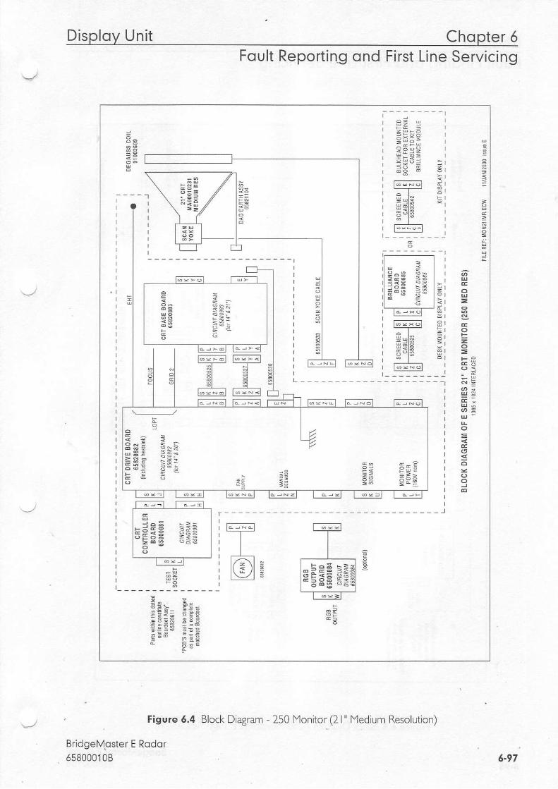
Disploy Unit Chopter 5Foult Reporting ond First Line Servicing
Figure 6.4
Bridgelvlgster E Rodor658000108
Block Diagram - 250 Monitor (2l" lYedium Resolution)
5.97
3 = c
r E H =
f - - : t a -=f ; '1 4 - I '
EE€E SEF l rI . E 8 E E E E I ;t o t ;*_r--T-;
f ; * r l-T_-___r._ E
l*:;; =sH'l ]ii!fl
EE:::c:: " - e E 9
rEi
; E
E -
5 * :
rEE - ! $ ]E E€ :E l Fz FrE
4= -Fa
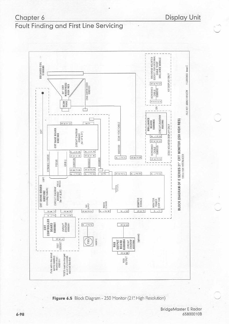
Chqpter 6 Disploy UnitFoult Finding ond First Line Servicing .
-
Figure 6.5 Block Diagnm - 250 Monitor (2l11 High Resolution)
BridgeMdster E Roilor65800010B6.94
;
=
= : e ;
= = ' = i I
;
T;:- tr--nfr ----
__-]I
FE;E rsc I i1 3
- l l--f --;f i
9,4
Ei ; - FEe=i iE EF;€ = € ; n *
6 r
F a
+ -: E ;
a d ! F : E r F=e €Fe
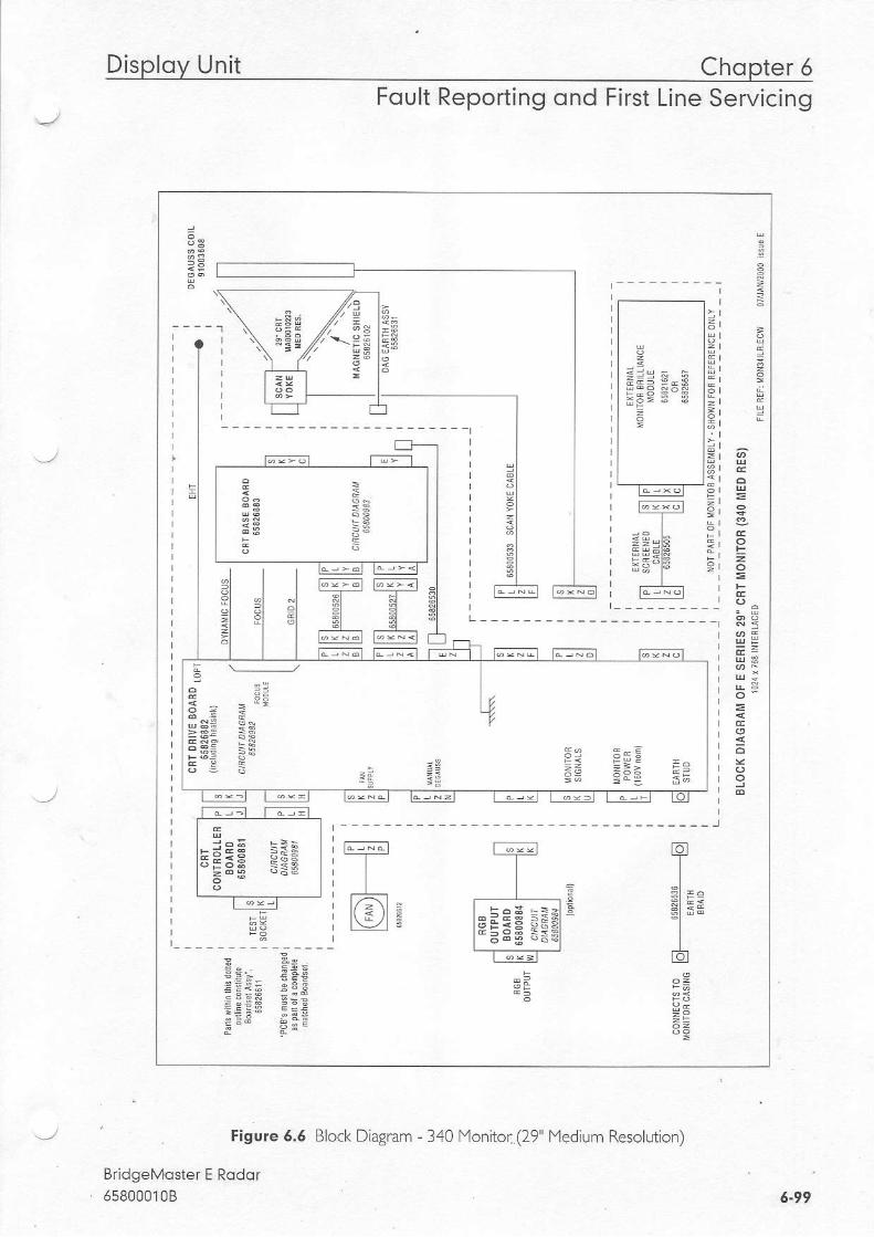
Disploy Unit Chopter 5Foult Reporting ond First Line Servicing
Figure 5.6
EridgeMoste. E Rodor65B000108
e
G 4
folI
."1El =*- l
It o l
eZ
= e
: = r - = F g= E : € ! : d=E€E C:EF - . p ; E
t ' d/ / , '
j "
//. \-?ar 2 E
5 : E3 3 :
{ E
E
zA ;s5 *;
Block Diagram - 340 Monitor (29" Medium Resolution)
6.99

Chopter 5 Disploy UnitFoult Finding ond First Line Servicing
ntentionally Blank
BridgeMoster E Rodor6s80001086.100
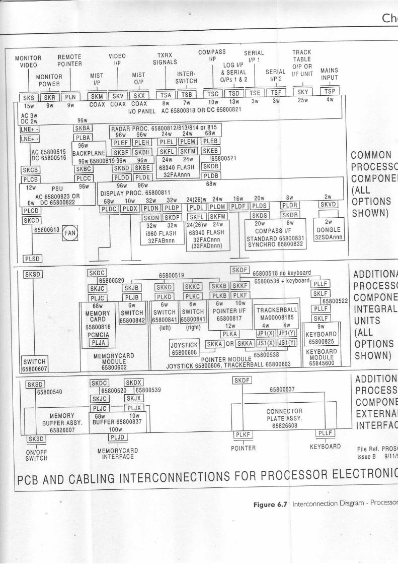
Ch,
MONITOR SEMOTEVIDEO POINTER
VIDEO TXRXSIGNALS
C O M P A S S S ESIAL
| "o*'ro, I'L'E"_-L
6580051565000516
INTER'swlTcH__ L_
SERIALllP 2
TfrACKTABLEO/P ORI/F UNIT M A I N S
I N P U T
ILNE-.l--r-lAclDc___r_
l sKcB I
C O M M O NPR0CESSCC O M P O N E I{ALLOPTIONSsHovvN)
ADDITIONIPROCESS(C O M P O N EINTEGRALU NITS(ALLO PTIONSS H O W N )
PLBA9 5 u I r r L L ' l i ! ! i i L
arcxpuHel llxeTllTKBH I96w 65800819 96w 96w
sKgc ISKBD SKBE
1 5 $
AC 3vlDC 2w
COAX COAX COAXVO PANET
gf , lw low 13' lv
AC 65800818 0R 0c 65800821
96{ 96v/DtSPIAY PRoC.6580081168e, 1 ow 32Lq4l-3946-IL-!1!
(leil) (ighl)
Ftst,cil Wmn is\xotmTxillls' t'tl
.,. " t'. *tEooJiJ,: il,^%1'r'&*;**
POII{TER UF65800817
12v
SWITCH65800841
MEMOBYCARDMOD{JLE65900602
KEYBOARD65800825
KEYgOARDM O D U L E65815600swtTcH
65800613
6580051S 65800518 no keybqq4!65800536 + keYboaro
l sKoc l l s l (Dx I*l-e ssooszo l6s8oos:s
I@ IsKJX l
--r--i.IEMORYCARD
INTERFACE
INTERCONNECTIONS FORPROCESSOR ELECTRONI(
M E M O B YBUFFER ASSY.
65826607_ T
POINTER
_ --T-
KEY9OARD
ADDITIONP ROC ESSCOMPONTEXTERNAIINTERFAC
File Rel. PR0s(lssu€ B 9/11/l
---T---ON/OFFSWITCH
C O N N E C T O R9LATE ASSY.
6582660868Yr 10w
BUFFEB 65800837100\|/
PCB AND CABLING
Figure 6.7 Interconnection Dragram - Pro'essor

S-Bond Sconner Uni t Chopter 5Foult Reporting ond First Line Servicing
5.2 S-Bond Sconner Unit
5.2.1 MognetronReplocement(Sconner Unit - Mostheod Tronsceiver)
Atthe Scanner Control Unit set the isoating switch to the 'OFF' position and lock it. Rotatethe antenna until the front face is point ng away from the transceiver.lsolate the radar from the ship's mains supply using the iso ating switch provlded.
Refer to Figure 6.8, and remove the transceiver cover from the scanner unit. Refer toFigure 6. 3, and follow the procedure for removing and replacingthe magnetron.
lYagnetron Current (Scanner Unit with Integral Transceiver).,_,/ . When a l'lagnetron is replaced, the magnetron current mus'r be set as follows:
On the Trigger pcb set links LK5 and LK6 to position 2-3.Reconnect the ship's mains supply, and switch the radar ON.Wait 3 mlnutes for the magnetron time delay to exp re, and select long pulse.Set the magnetron current as detailed in Figure 6. 14.
solate the radar from the ship's mains suppy using the solating switch provided.Reset LK5 and LK6 to position -2.PFpl" _e tL^ -r"-s.-iver cov-r.
' 3,2.2 Mognetron Replqcement (Bulkheod Tronsceiver)
lsolate the radar from the ship's mains supply usinS the isoat ng switch provjded.
Refer to Figure 6.9, and remove tmnsceiver cover. Refer to Figure 6. 13, and {olow theotoced.r- br ." .1 6y6qs-d "pa i^g f ,e napn-r o-.
f'lagnetron Current (Bulkhead Transceiver)
When a magnetron is replaced, the magnetron current must be set as fol owslReconneclthe ship's mains supply, and switch the radar ON.Wait 3 minL,tes forthe magnetron time delayto expire, and select long pulse.Se. Lre nagnerron cr'-F'l a( oeldilcd n Fg r'e o. a
lsolate the radar from the ship's mains supply using the isolating switch provlded.P"pla.e re .-an,ceive. cover.
5.2.5 Heoding Mqrker Replocement
At the Scanner Control Unit setthe isolating switch to the'OFF' position and lock it. Rotate' the antenna until the front face is pointing away from the transceiver.
BridgeMoster E Rodor658000108 6-105

Chopter 5 S-Bond Sconner UnitFoult Finding ond First Line Servicing
lsolate the radar from the ship's mains supply using the isolating switch provided.
Refer to Figure 6.22, and remove the Peformance l''lonitor cover. The location o{the PulseBearing pcb is shown in Figure 6.23. Remove the f,vo securing screws and remove the pcb.Reolace the Dcb and secure with two screws. Two dowels ofdifferent diameters locate thepcb in the correct orientation.
5.2.4 Heoding Morker Al ignment
Alignment ofthe Heading Marker is achieved viathe Initialisation menu atthe Display Unit.
BridgeMosler E Rodqr65800010B6.704
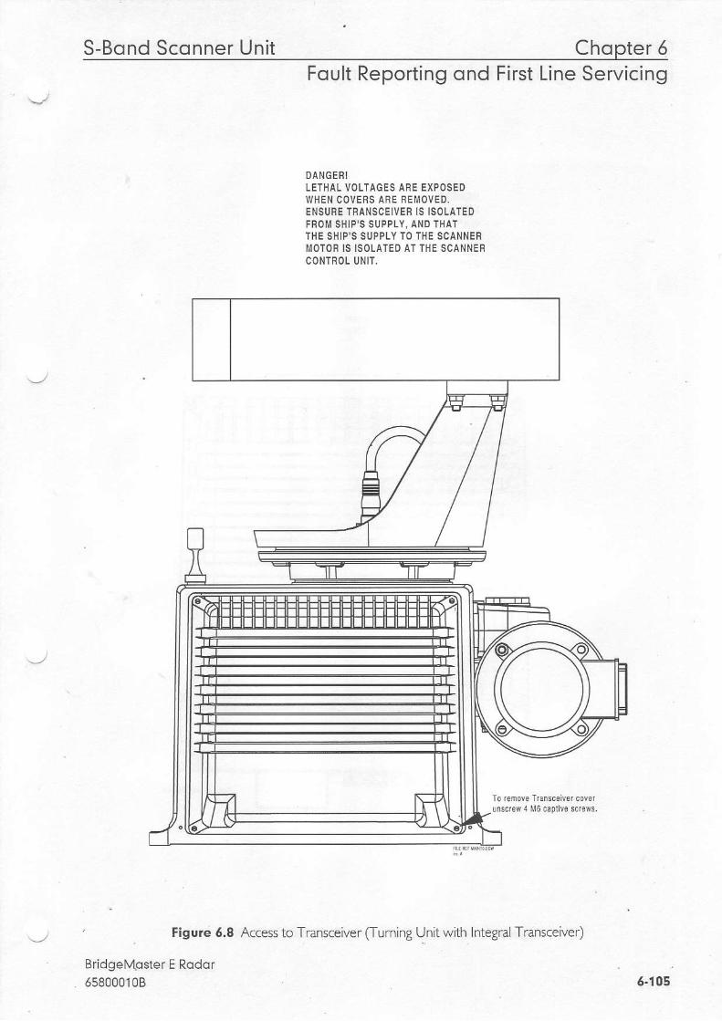
S-Bond Sconner Unit Chopter 5Foult Reporting ond First Line Servicing
9ANGEFILETHAL VOLTAGES ARE EXPOSEDWHEN CoVERS ABE FErrr loVED.ENSURE TRANSCEIVEF IS ISOLATEDFROM SHIP'S SUPPLY, AND THATTHE SHIP'S SUPPLY TO THE SCANNENi iOTOR IS ISOLATED AT THE SCANNEFCONTROL UNIT,
Figure 6.8 Access to Transceiver (Turning Unit with Integral Transceiver)
Rri/l^6N,,t^.r6/ E o^.1^r
65800010B
Io remove Trafsc€iv6r covar!nscrew 4 l,l5 capllv6 screws.
6-105
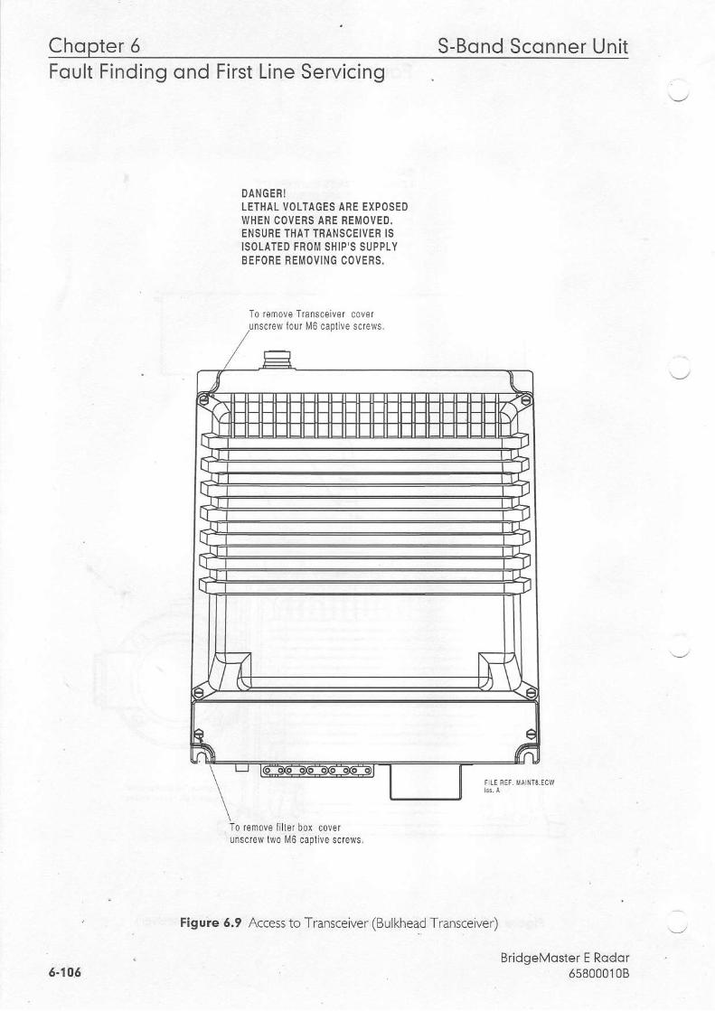
Chopter 5 S-Bond Sconner Uni tFoult Finding ond First Line Servicing
DANGERILETHAL VOLTAGES ARE EXPOSEDWHEN COVERS ARE REII i OVED.ENSURE THAT TRANSCEIVER ISISOLATED FNO ISHIP'S SUPPLYBEFORE REMOVING COVEf,S.
To iefiove Transceiver coverew Iouf l\rl6 caplive screws.
To r-.move iiller box coverunscrew llvo M6 caplive scfe\rvs,
Figure 5.9 Access to Transceiver (BLrlkhead Transceiver)
BridgeMoster E Rodor658000',l0B6.105
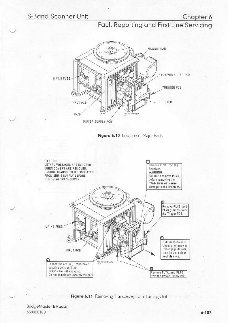
S-Bond Sconner Uni t Chopter 5Foult Reporting ond First Line Servicing
A G N E T R O N
RECEIVER FILTEF FCB
TNIGGEN PCB
MA NS FU
MA NS FUSE
BridgeMoster E Rador6s8000108
FECEIVER
Figure 6.10 Location of lYaior Parts
DANGERILETHAL VOLTAGES AFE EIPOSEOWHEN COVERS ABE BE]\4OVED.ENSUFE TBANSCEIVER IS ISOLATEDFROII SHIP'S SUPPLY BEFOREFEMOVING ' f ,ANSCEIVER
damago lo lhe Seceiver,
P L Y K ( l l l l e d ) l r o mlhe l r igger PCB.
Loosen lhe s ix (M8)rJansce ver
rhreads de i !s l en9aginq.Do norcomp ele ly uf<rerrhe bol
Fenove PLTA, and PLTGrrom lhe Power SuoDlv PCB.
Figure 6.11 Removi-g 1 rans.-iver r 'om Turning Jnit
6.107
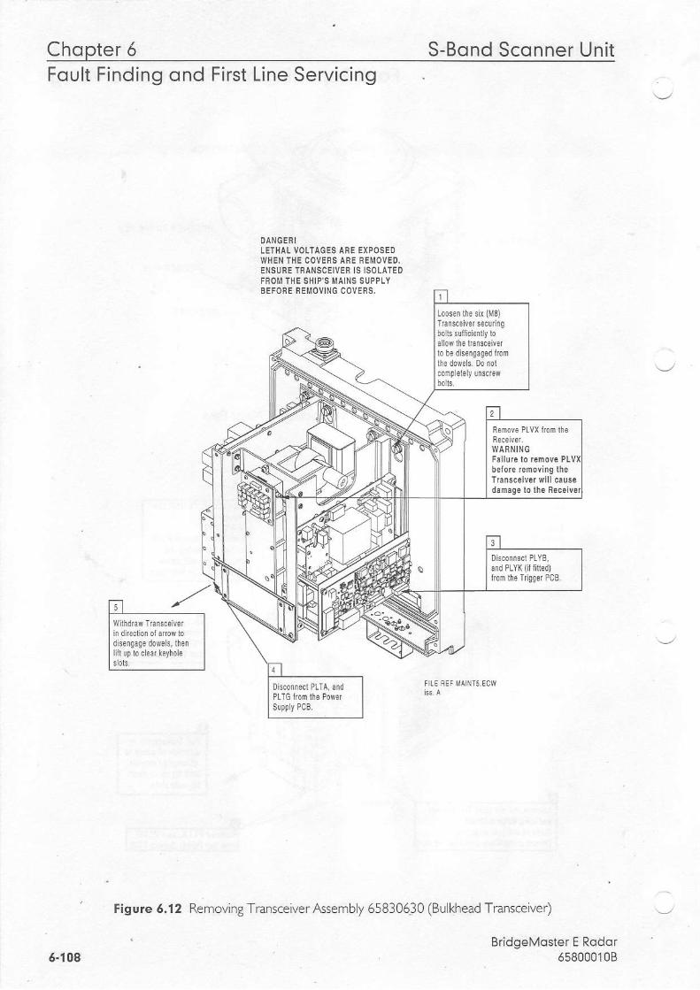
Chopter 5 S-Bond Sconner UnitFoult Finding ond First Line Servicing
LETHAL VOLTAGES AFE EXPOSEDWHEN THE COVERS AFE REMOVED.ENSURE IFANSCEIVER IS ISOLATEDFROIT THE SHIP 'S MAINS SUPPLYBEFORE FEMOVING COVEFS,
Figure 6.12 Removi.g Tians.eiver Assembly o5830630 (Bulkhead Transceiver)
BridgeMoster E Rodor6580001086-108

S-Bond Sconner Unit Chooter 6Foult Reporting ond First Line Servicing
WARNING:Ensure that the scannersupply is lurned ofl at theScanner Cont fo l Uni t . Remove six M6 screws
l0 remove magnelron lromheatsink.Note:Two dillefenl screw lengths
TPl OO
It{agnelron cufrentsetting label.
BridgeMsster E Rodor658000108
Replac€menl is lhe revers,o
magnelr0n currenl musl besel up as in 'SeltingMaqnetron Currenl'
Figure 6.15 lYagnetron Replacement
a-109

Chopter 5 S-Bond Sconner UnitFoult Finding ond First Line Servicing
0n the Trigger PCB set:LKs, and LKO to 2 - 3.This is the service position,and wil l allow the tfansmitteflo transmit when lhe anlennais stalionary,
Restore the ship's suppiyto lhe Transceiver.Swilch on al the Displayand wait 3 minules lor t imer.Select Long Pulse, Transmitat the Display.
0n the l i lodulalor PCB measurethe vollage belween TP100 andg round.NolelA DVLI with an input impedancegreater lhan 10 l, lohrns must beused for lhis measurenenl. Useoi a meter with lower impedancecould result in damage to themagnetron.
Adjust RV1 on the Power SupplyPCB to give the sane voltage onTP100 as is recorded on the labelon the puise lfansJorner on lhel!4odulalor PCB.
BridgeMoster E Rodor6580001086.710
Figure 6.14 Setting lYagnetron Current
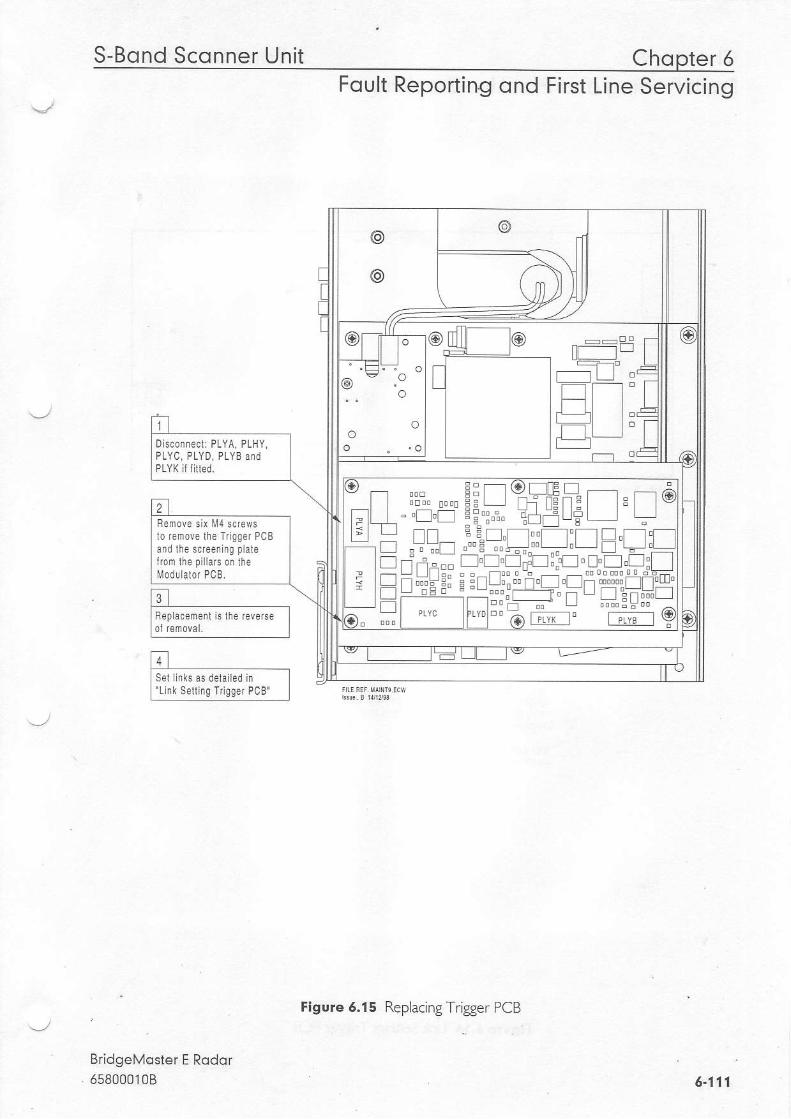
S-Bond Scqnner Unit
BridgeMoster E Rodor
Chopter 6Foult Reporting ond First Line Servicing
ttlRepracement is lhe rcverse Iloi,enovar. i
, lS e i f k a s d e r a i t e d i n l'Llnk Se ing ldgger PcB' l
Flgure 5.15 Replacing Trigger PCB
f l L__.1f r ----lt t lt-t IT L It -
@ : . o. . o
oo
Disconnecl : PLYA PLHY,
PLY( it I lled.
t a
+D"
TIr-
- f tl EI El L lr f t
lo remove ihe Iri99e. PCB
Moduhlor PCB.
6.171
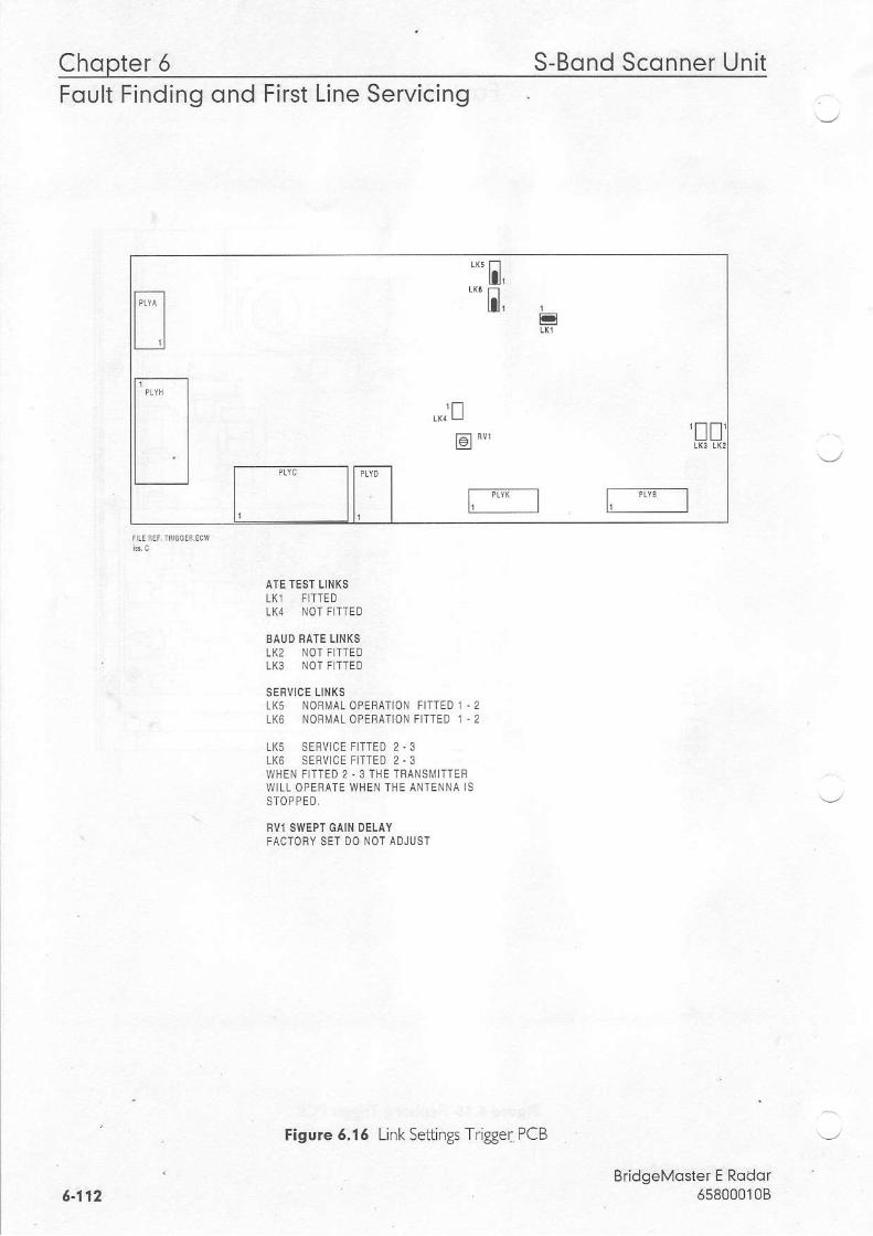
Chopter 6 S-Bond Sconner UnitFoult Finding ond First Line Servicing
AIE TEST LINKSLKl FTTEDLK4 NOT FITTED
EAIJD RATE L'NKSLK2 NOT FITT€OLK3 NOT F]TTED
SEFVICE IINKSLKs NORMAL OPERAIION FITTEO 1 .2LK6 NOBMAL OPERATION FITTED 1 .2
LK5 SERVICE FITTEO 2 ,3LK6 SERV1CE FITTEO 2 .3WHEN FITTED 2,3 THE TRANSMITTEFWILL OPERATE WHEN ]HE ANIENNA ISSTOPPEO,
BVI SVIEPT GAIN DELAYFACTOBY SET DO NOT ADJUST
\-2
BridgeMoster E Rddor65800010B
nil ,.;!
rEr Bv, !
l;*_-l r-"*__l
e-112
Figure 6,16 Linl Settings Trigger PCB

Disploy Unit Chopter 5
I 1 - l ,I To remous lhe M0dural0r PCBI1 il h r 6l nm*srylo remwe II lhe Tfansceivsr assembly as II detared previo|lsry. I
trtI Femove I r isser PcB as
I dela i red prevousy
Foult Reporting ond First Line Servicing
BiidgeMoster E Rodor658000108
D sconnecl luo na9fe l ron
fuIl':
D| k_ ,Fep acerienl is lhe reverse01 renova. Belore replacinglhe Trigger PCB check ihslnk seilings on the Modulalor
Figure 6.17 Replacing Modulator PCB
6-115

Chopter 6 Disploy UnitFOUTI FtnOlnq ono Ftrst Lrne bervtctng
LK2LK3
NOTE THAT LINK 1 13 CONFIGUSASLE FOF HEAIEF IUBNDOWN ON 25KW X-BANDNOTE THAT LINKS 2 & 3 ARE HAFOWIRED FOR SPECIFIC USEAGE,
TEST POINTS:TPlOO MAGNEIFON CUFFENT MONITOFTP]O] CHANCE TRIGGEFTPlO2 MODULATORTFICGEF
MoDULATon LINK SETINGS F0B 65810812 / 65825812 / 65830812
Figure 6.tB Link Settings - f4odulator PCB
BridgeMoster E Rodor658000108
I lpo*o-| I l t ^I I (9e'l l > - <+ l
If t |I l l . s
l
I I f T T T T T I , , , " Et L l t l l t +
!e '- .,-!r tuEF r--:-----r r r:< l**
" * * | | U !u^| | r i ] r r #** ho l .
i r l I ll..l Lr + | ^ : "r io!' * " - + j f t ; f t ' ' " ) f t 1
' " ) ( l ' ' ' "-- ------l -r----l
or)\
A
E -*ogr
=r[ENT BOAFD 6580]816
S.BAND 1O KW X.BAND 25 KW X.BANDLK1 FITTED 2.3 FITTED 1 .2 FITTEO 1 ' 2 FOR MAGNETFON MG5424
LKI FITTEO 2 .3 FOF MAGNETRON M14 '8
LK2 FITTED NOT FITTED NOT FITTEDLK3 NOT FITTED FITTEO NOT FITTEI]
5-11.4
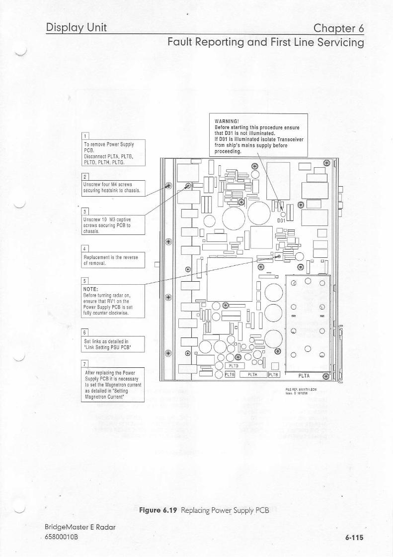
Disploy Unit Chopter 5Foult Reporting ond First Line Servicing
l-61 ,I Ssl linksas dehiledin I| 'Liik $lrhq Psu PcB J
titI Ar lof f6pacrg lhe PowsI supply PCB il !s n-'cossaryI lo sel lhe Magrelrcr cur"ailI as delailed in setrng
I Masfelron cmenl'
BridgeMoster E Rodor558000't0B
WAhNING!Before srarling lhls procedure ensurerhar 031 is nor lllufiinaled.ll D3l is illuminaled lsoldte Trdnsceiveriiom ships mains supply befoe
i,r^)r, \ _ /
ilt| l L l
l l ( ) h.l l l l l l^l-----.1 n nl )I a ! : v ' ] ' . L l l l l \ - , _ /I f l t . t - L U
I t ! I- l / - \ | ) T J / i
11 )/ \X'no^=\ -/n z--tY.* Xr=t
YB8d="1oT-'- . \ . - / r nu | ! |
19, r f t
L@ E
t ln
I r r' r -J n o o n@u tl
securi9 heals nk l0 chass s.
o o oNOTE:
Figure 6.19 Replacing Power Supply PCB
6 .115
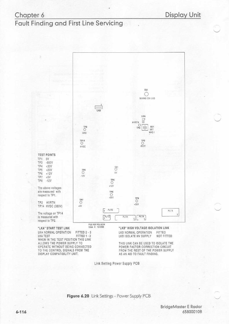
Chopter 5 Disploy UnitFoult Finding ond First Line Servicing
TEST POIN]S
TP3 6OOV
TP8 ,12V
TP2 HVRTNTP14 HVDC (380V)
.LKA' STANT TEST LINT
LKATESTLI(A NORMAL OPEFAT]ON FITTED 2,3
"LKB' HIGH VOLTACE ISOLATIOI,I LINKLKB NORMAL OPERATION FIlTEDL|(B lSOLAIE HV SUPPLY NOT FITTEO
THIS LIN( CAN BE USED TO ISOLATE THEPOWER FACTON CORFEC]ION CINCUITFFOM THE flEST OF THE POWEF SUPPLYAS AN AID TO FAULT FINDING.
FITIED ! - 2WHEN 1N THE TEST POSITION THIS LINKALLOWS THE POWEB SUPPLY IOOPERATE WITHOUT BEING CONNECTEDTO THE CONTFOL SIGNALS FSOM THEDISPLAY COMPATIBILITY UNIT.
Link Set l ing Power Supply PCB
BridgeMoster E Rodor658000'l0B
o
:
ilo
o
'9lEl *'
o
oI'
o
ooo
F " . I[g r---"r__ir"l
6.11.6
Figure 6,20 Link Settings - Power SupplyPCB,
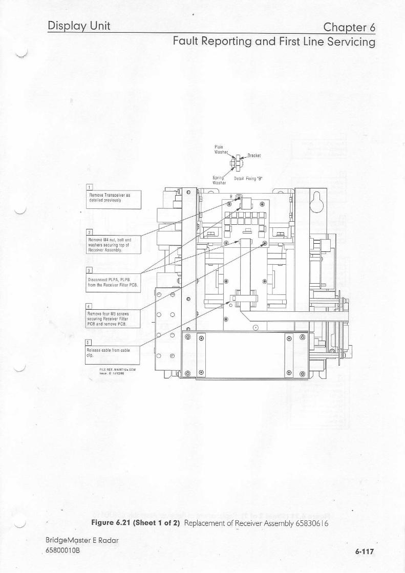
Figule 5,21 (Sheet 1 ot 2)
BridgelVoster E Rodqr5s800010B
Chopter 6Foult Reporting ond First Line Servicing
lov Unit
Replacement of ReceiverAssembly 658306l6
6-117
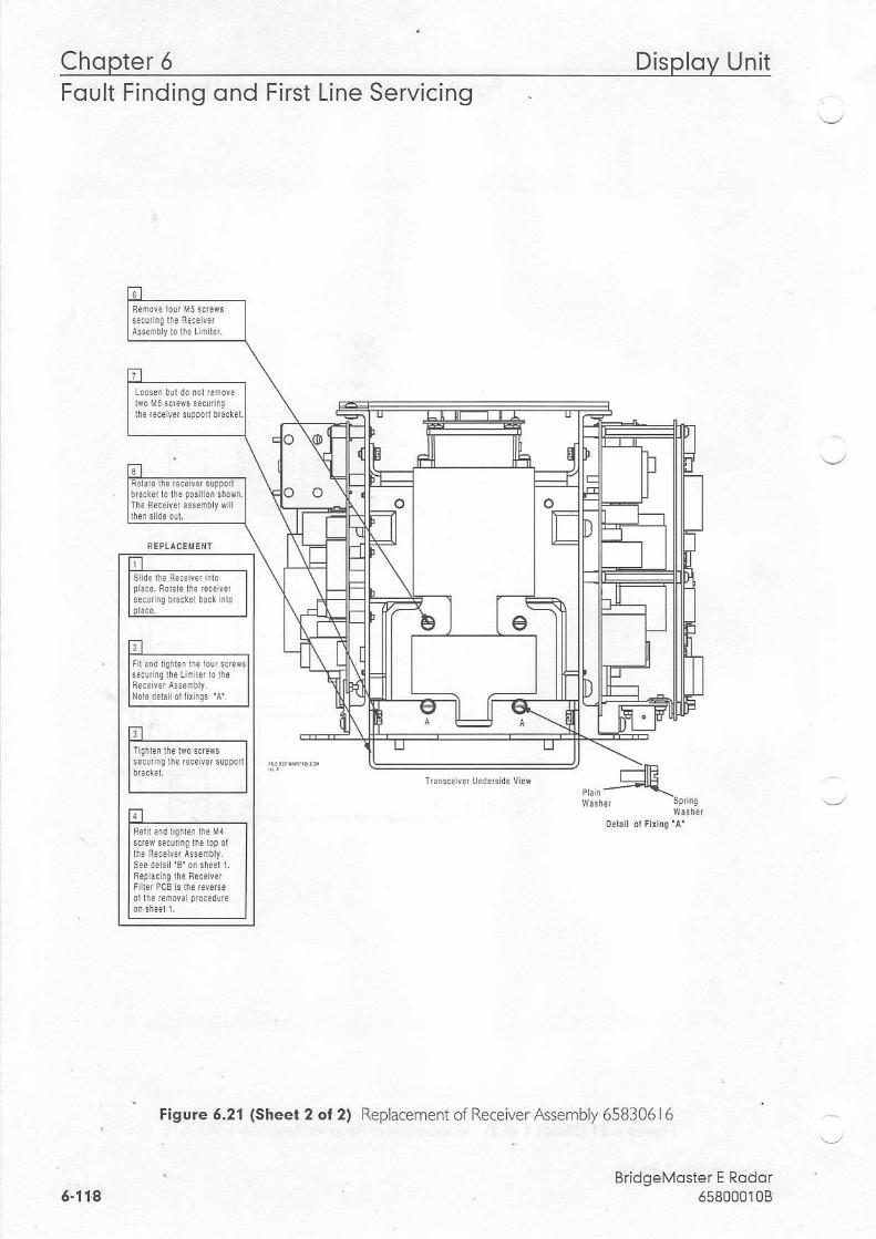
Chopter 6 Disploy UnitFoult Finding ond First Line Servicing
Figure 5.21 (Sheet 2 ol2) Replacement of Receiver Assembly 658305l6
BridgeMoster E Rodor5580001086-11.5

Disploy Unit Chopter 6Foult Reporting ond First Line Servicing
DANGEFILETHAL VOLTAGES ARE EXFOSEDIIIHEN COVEFS AFE REMOVED.ENSURE TRANSCEIVEF IS ISOLATEDFFOM SHIP'S SIJPPLY, AIlDTHATTHE SIIIF'S SUPPLYTO THE SCANNERMOTON IS ISOLATED AT THE SCANNEFCONTFOL UNIT.
Figu.e 6.22 Access to Pedormance l,lonitor andBearing and Heading 14a'ker PCB
BridgeMoster E Rqdor65800010B 6.119
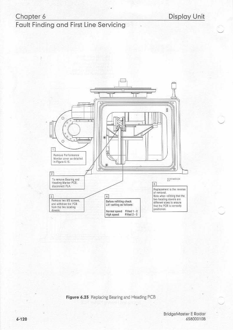
Chopter 5 Disploy UnitFOUtr Ftnotno ono Ftrsr Ltne Servtctno
Flgure 6.25 Replacing Bearing and Heading PCB
BridgeMqster E Rddor65800010B
REph.emeil is ihe reve66
5-120
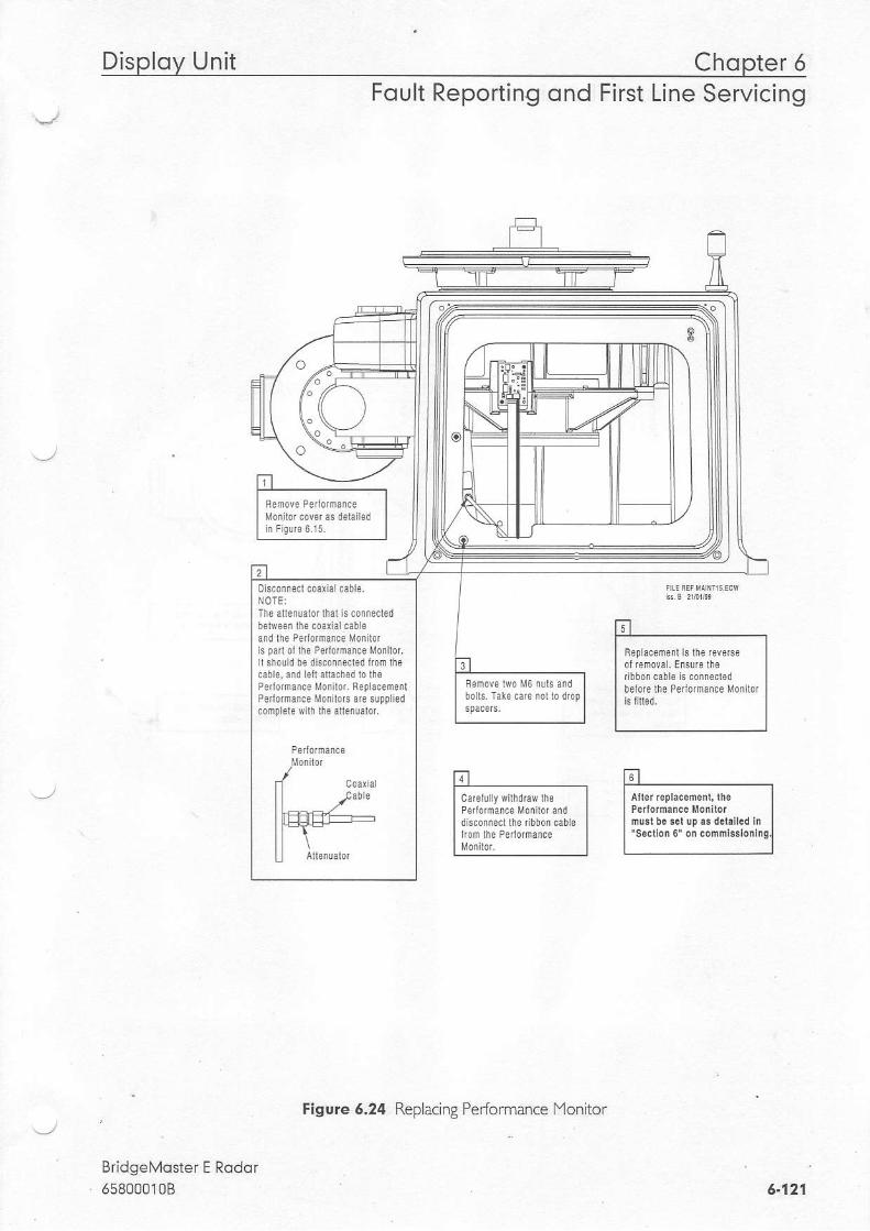
Disploy Unit Chopter 6Foult Reporting ond First Line Servicing
belore lhe Peilormaice Monllot
BridgeMqster E Rodor65800010B
NOTE:Th8 allefualdtal h coiiecled
and lhe Pe o'nance Monihrispa ol lha Pdlornance Moiilor.lr shorld b6 discofnecred lmm lhecabh, and lefi anach6d lo lheP{loroance Moiilor. ReplacemenlPedoman.e Monltore are supplledcomp ek wilh the allenualor.
tl , f;ll cder r r r f lno , {0e f f tn ,
"o ' * " . * , , * " l
I ,oar rde l r 'd , rda ,d | | pd toh .nE Mon i ro r II d mre( r 'F r iboonLabe | | mus l bo 561 up . . dek i led in I
l ; : l , i l*"". ' I l 'sr' 'on0'otrconmhddrnql
Eigure 6.24 Replacing Peformance lYonitor
6.121

Chopter 6 Disploy UnitFoult Finding ond First Line Servicing
tr --..----_I
qeoa r f t n l , \ i \ . | _
Figule 6.25 Replacement of Fan Assembly
BridgeMoster E Rodor6580001086-122
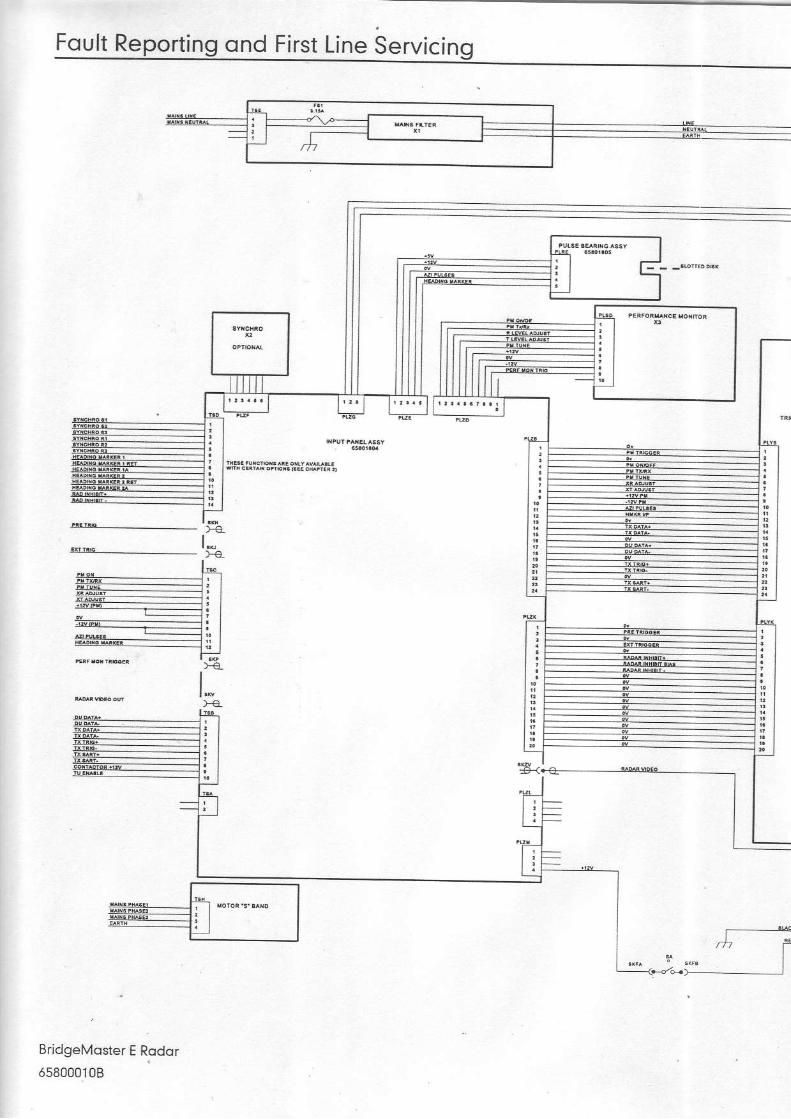
Foult Reporting ond First Line Servicing
**..:tiPJ55i?$:aw:t..
re_
Bridgelvloster E Rqdqr
658000108
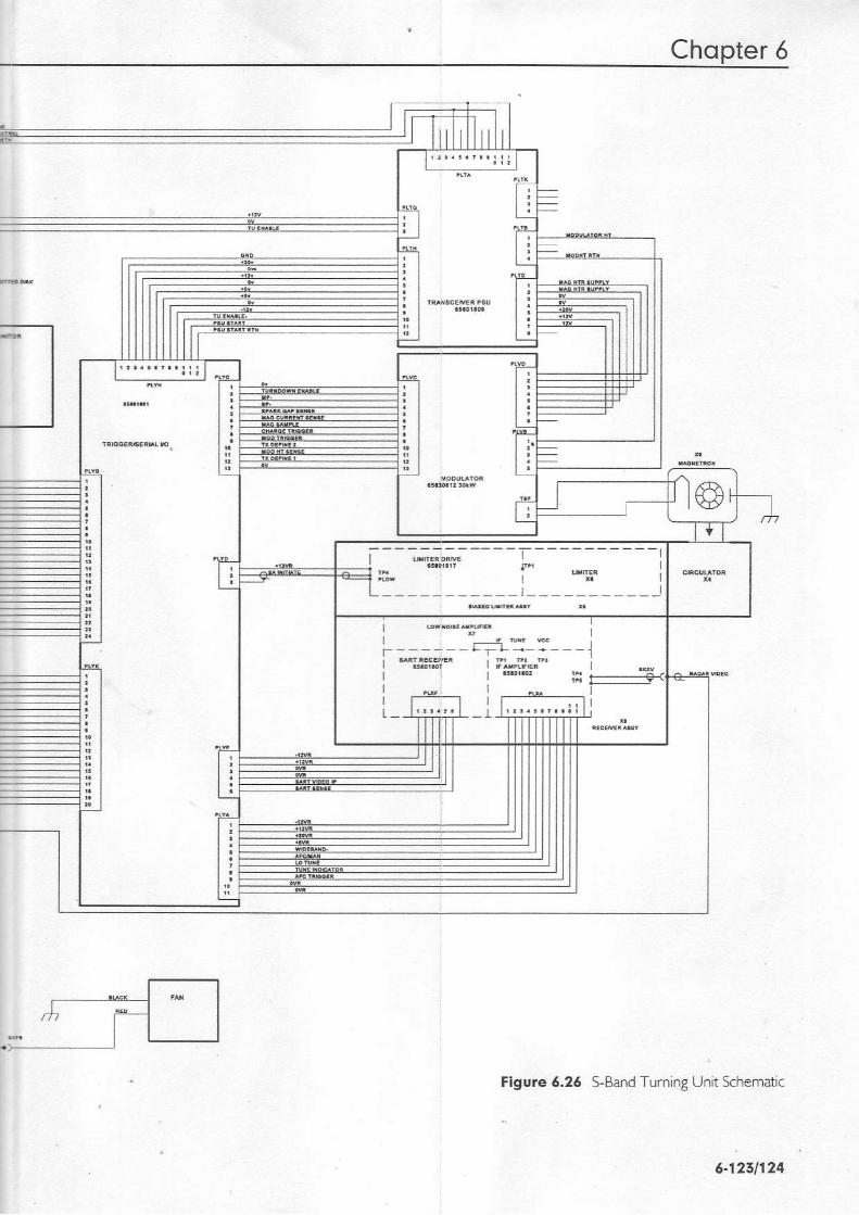
Chopter 5
- - - : : : - - - - - - - - - - - - - - - -
lI utrE9ltYE : ,F l
i; | *,iil I
. , - , , ) , , , - - l
F r;a . -III
Figure 6,26 q-Band [u.n ng -1.r s.hemair.
6-1211124
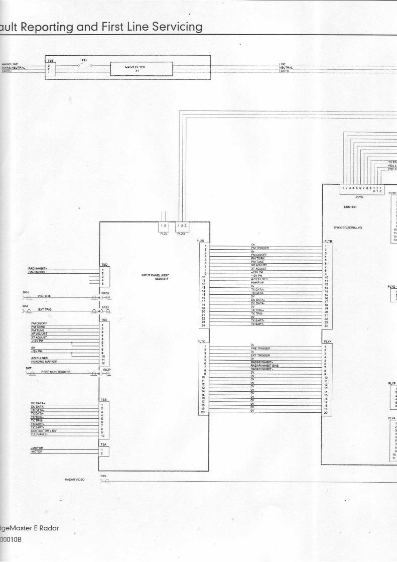
rult Reporting ond First Line Servicing
!.=-i€.E---_---a-)-a
)+ q@ )a
lgeMqster E Rqdor
000108
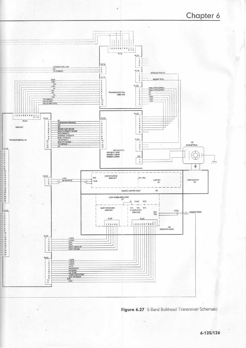
Cho ter
aigure 5.27 9Band Bulkhead TGnsceiver Schemdif
- - - l
III
b ; - E
5.1251125

X-Bond Sconner Unit Chopter 6Foult Reporting ond First Line Servicing
5.5 X-Bqnd Sconner Unit
3.3.1 Access to Mqstheod TronsceiverSet Transceiver Unit to Standby and switch offthe D splay Unit from the front panel.lsoate and rer.ove both ShiD's Switch Fuses in DC systems.lsoLate the radar from the ship's mains supply using the isolating Switch provlded for ACsystems.Turn the antenna into the service position, i.e. across the Transceiver axis, clear ofanyobstructrons.Undo the lour captive bolts on the unders de of each the upper casting. These secure theupper casting to the base casting.
Raise the upper casting lnto the upright position and ensure thol lhe support sloyengoges in the locked position. The sliding locking bolt should be pushed lo the' bottom of the slol in the sloy to prevent inodve enl release ot lhe upper cdsting,Refer to Figure 6.28.
5.5.2 Access to Bulkheqd TronsceiverSet Transceiver Unit to Standby and switch offthe Display unit from the front panel.lsoate and remove both Shio's Switch Fuses in DC svstems.lso ate the radarfrom the ship's mains sLrpp y using the lsolatlng Swrtch provided for ACsystems.Undo the tour screws that retain the upper cover to the lower chassis and lift c ear.
5.5.5 Removing ond Replocing the Trqnsceiver from MqstheodTurning UnitRefer to sub-section 3.3. | (Access to lYasthead Transceiver), paying attention to all safetyaspects. Check that the transceiver is fully isolated from the ship's supply.
" '/ Note The Masthead and Bulkhead Trenscetier Units are tdentical and only mnordiferences exist in terms affr.\tures.
Disconnectthe cables from the following sockets:-SKV Video co-axial cable to receiver assembly.
. PLYB Ribbon cable to Trigger PCB.PLTK Cable frorn PSU to lYotor Drive PCB.PLTA Cable from PSU to Input Flker PCB (mains supply).PLTG Cable from PSU to Input PCB.
Refer to Figure 6.30.Stuated around the base ofthe Circulator plate, release the four lY6 captive screws that holdthe microwave assernblyto the wavesuide transition.
- Remove the three screws that hold the lYodulator heatsinkto the chassrs.Slacken the two large bolti that hold the PSU heatsinkto the chassis.
BridgeMoster E Rodof.65800010B 6'127

Chopter 5 X-Bond Sconner Uni tFoult Finding ond First Line Servicing
5.5.4 Removing ond Replocing the Tronsceiver from BulkheodTronsceiver ChossisRefer to sub section 3.3.2 (Access to Bulkhead Transceiver), paying attention to all safetya.p".I.. Che(t thd. the T o^srever is fullr solated fror qe srip s s-pp'7.
Note - The Masthead and Bulkhead Tnnscetver Units are identtcal and only minordiferences exist in terms off^tures.
Dlsconnectthe cables from the {ollowing socketst-SKV Video co axial cable to receiver assemby.Dl YB R bbo- .able 10 Trigg"r DCB.
PLTK Cable from PSU to Inprn PCB (motor supply)DL-A Caole lr o'n PSU .o Inputri l.er DCB '-nai-s.upplyt.PLTG Cable from PSU to Input PCB.
Refer to Figures 6.30 and 6.35.Situated around the base ofthe Circulator plate, release the four f'16 captive screws that hold
. the microwave assenjbly to the waveguide transition.
The PSU heats nk has slotted holes that enable the transceiverto be s id upwards (towardsthe m;crowave outpLrt trans itio n) and removed without fully removing the |r',/o bolts. Befores iding up and removing the Transceiver, ensure that no cables are caught on any ofthemetalwork to avoid damage.
ReplocementThe replacement sequence is as follows:Locate the Transceiver approximately onto the upper casting using the two large slottedholes in the PSU heatsink.Slacken the tv,/o screws that hold the PSU chassis plate to the lYodulator chassis plate, seeFigure 5.30.Slacken the screw that holds the Circulator mounting plate to the PSU chassis plate.
The three screws in the lYodulator heatslnk should be ftted but only portiolly tightened.The four lY6 microwave assembly retaining screws can now be fully engaged and tightened. .,_-/The three screws in the lYodulator heatsink can now be fully tlghtened.The two large bolts in the slotted holes in the PSU heatsink can now be fully tlghtened.The two screws that hold the PSU chassis pate to the faodulator chassis plate can now befully tightened.The screw that holds the circu ator mountlng plate to the PSU chassis can now be fullytightened.
Note This sequence ts impotTant to ensure that the microwave a/ignment takes pn:oit/ nterms af mechantca/ to/eances.
Rcn : . a : . r h ac r cm^ .a . ] a : r i a f
Bridgel.r'loster E Rodor6580001086.124

X-Bond Sconner Unit Chopter 6Foult Reporting ond First Line Servicing
Remove the three screws that hold the lYodulator heatsinkto the chassis.Slacken the two large bolts that hold the PSU heatsinkto the chassis. The PSU heatsink hasslotted holes that enable the transceiverto be slid upwards (towards the microwave outputtransition) and removed without fully removingthe two bolts. Before sliding up andremoving the Transceiver, ens u re that no cables are caught on any of the metalwork toavoid darnage.
Note On Bulkhead Tnnsceiverc, a sma/l cltp is ftted to the chassis to retain the /ower edgeofthe Modulator PCB and suppott p/ate. This b purely a slide-in frxture and does not requireundotng.
RepldcementLocate the Transceiver approximately onto the chassis using the two large slotted holes lnthe PSU heabink.
. Ensure that the small clip fitted to the chassis engages the lower edge ofthe lYodulator PCBa-d suppon plaLe duri^g.re replacenen p'ocess.
Slacken the l&o screws that hold the PSU chassis plate to the iYodulator chassis plate, referto Flgure 6.35.The three screws in the lYodulator heatsink shou d be fitted but only pqrtiolly tightened.The four lY5 microwave assembly retaining screws can now be fully engaged and tightened.The three screws in the f4odulator healsink can now be fully tightened.The two large bolts in the slotted holes in the PSU heatsink can now be fully tightened.
Nob fhis sequence is impaftant to ensure that the m/.rawave a/Enment takes pianry interms of mechanical tolerances.
Replace aLl cables removed earlier.
5.5.5 Mognetron Replocement - Mdsthedd qnd BulkheqdTronsceiversRefer to sub section 1.3. (Access to lY asth ead Transceiver), paying attention to all safetya.oe.1s. CLecl, that tLe .ran,ceiver is '-lly solated 'ron the ship s sJpply.
Refer to Figure 6.30.Disconnectthe lr'/o EHT leads from the l'4odulator PCB terminal block.Remove the four screws holdingthe lYagnetron to the Circulator plate,
ReplqcementReplacement is the reverse ofthe removal processEnsure that the polait} ofthe EHT leads is correct. The PCB is marked 'Y' for yellow and'G' for green.Ensure that any earth bonding Ieads to the l4agnetron are refitted
_ After leplocement the mcgnetron current must be sei up os ln the followlnq sub.. section.
BridgeMoster E Rodol. 658000108 6.129

Chopter 6 X-Bond Sconner UnitFoult Finding ond First Line Servicing
5.5.5 Sett ing the Mognetron CurrentRefer to Figure 5.36 forthe necessary procedure for setting lYagnetron current.
3.5.7 Trigger PCB - ReplocementRefer to sub section 3.3. I (Access to lYasthead Transceiver), paying attention to all safety
"specs. Checl . 'a. .f, e .r ars.eir er, fully i>o " ed : o-n lhe 5h p > suppl/.
Refer to Figure 6.37 for the necessary procedure for replacing the Trigger PCB.
5.5.8 Trigger PCB - t ink Sett ingsRefer to Figure 6.38 for the necessary procedure for setting the link settings on the TriggerPCB,
3.3.9 Modulqtor PCB - ReplocementRefef to sub-section 3.3. | (Access to Masthead Transceiver), paying attention to all safety ,_,/a-pecL. C^e(1, thrt lhe 1.a'sce,ve' is '-ll/ i'olated 'ron the srip s sJpply.Refer to Figure 6.39 for the necessary procedure for replacingthe lYodu]ator PCB.
5.5.10 Modulotor PCB - l ink Sett ingsRefer to Figure 6.40 forthe necessary procedure for setting the Ink settjngs on thelYodulator PCB.
5.5.11 PSU PCB - ReplocementRefertosubsectlon3.3.l(AccesstolYastheadTransceiver),payingattentontoallsafet/aspe.lc. Cnec.rl-"rthe1?rsce.r 'eris fLl lv ,olated Io-r .re , ' io s,-pp[.Refer to Figure 6.4 | forthe necessary procedure for repaclng the PSU PCB.
5.5.12 PSU PCB - Link Sett ingsRefer to Figure 6.42 for the necessay procedure for setting the link settings on the PSU PCB.
5.5.15 Beoring ond Heoding Morker PCB - ReplocementRefer to s u b-section 3 .3 . I (Access to f'lasthead Transceiver), paying attention to all safetyasoecrs. Checl. -Lar rre transceiver s fully iso'ared f'om lhe sh p s supol'.
Refer to Figure 6.3 L.The PCB is attached to a suppoft casting and should be removed as a combined assembly bys ackening the two screws retaining the support casting, and then sllding it towards theoutside ofthe upper casting to clearthe screws.The PCB and support castrng can then be removed after the cable has been unplugged fromPLRE,
Note - When relittng the PCB to the suppott casttng there are dowel pegs ofdlferentdiametels used to locate the PCB in the coffect oientaflion.
- Before reitting the assembly, ch eck that the link LK I is set for eith er Normal Speed
' (pins | 2) 28 RPM or High Speed (pins 2-3) 45 RPM
. BridgeMoster E Rodor6-150 658000108

X-Bond Sconner Unit Chopter 5Foult Reporting ond First Line Servicing
3.5.14 Heoding Morker Al ignmentAlignment ofthe Heading f'larker is achieved via the lnitialisation menu at the Display Unit.
5.5.15 Receiver Assembly - Replocement (Mostheod)Refe r to su b-section 3 .3 . I (Access to lYasthead Transceiver), paying attention to all safetyaspects. Checkthatthe transceiver is fu ly isolated from the shlp's supply.Remove the Tmnscelver,ksembly as described at sub section 3.3.3.
Unplug the ribbon cable from the Receiverto the Receiver Filter PCBUnplug the ribbon cable from the Receiver Filter PCB to the Trigger PCB.Refer to Figure 6.30 for ocation ofthe screws securing the Low Noise Front End (LNFE) tothe Limiter.
Note The replacement Receiver b supp/ied wth the LNFE already litted.
Remove the four screws that hold the LNFE to the Limiter.Remove the bracket that secures the Receiverto the microwave assemby atthe Receiverend, and remove the whole Receiver assembly.Before iftingthe replacernent assembly, remove the Receiver Filter PCB frorn the od unit,and flt itto repacernent unit.
Replacement is the reverce ofthe removal process.
5.5.16 Receiver Assembly - Replocement (Bulkheod)Refer 10 sub-secrion 3.3.2 (Access to Bulkhead Transceiver), paying attention to all safet/aspects. Checkthatthe Transceiver is fulLy isolated from the ship's supply.
Refer to Figures 6.30 and 6.35.Unplugthe rbbon cable from the Receiverto the Receiver Filter PCB.
. , Unplug the rlbbon cable from the Receiver Fllter PCB to the Trigger PCB.- Unplugthe video co-axial cable from the Receiver.
Refer to Figure 6.30 for the location of screws securing the Low Noise Front End (LNFE) tothe Llmiter.
. Note - The replacement Receiver is supp/ied wrth the LNFE a/ready ftted.
Remove the four screws that hold the LNFE to the Limiter and remove the whole assembly.Before lltting the replacement assembly, remove the Receiver Filter PCB from the old unit,and fit itto replacement unlt.
PFolr, emenL is the .e\erce o he remotol process.
5.5.17 Performonce Monitor - Replocement- Refer to sub section 3 .3 . I (Access to IYasthead Transceiver), paying attention to all saiety
._,/ aspeds. Check that the transceiver is fully isolated fron] the ship's supply.
BadgeMoster E Rodol. 658000108 6.131

Chopter 5 X-Bond Sconner UnitFoult Finding ond First Line Servicing
Remove the l&o retaining screws that hold the Performance Monitorto the upper casting(see Flgure 6.3l) and withdraw the unit.Un screw the bar that retains the RF absorber to the body ofthe Performance l.'1onitor.Disconnectthe rlbbon cable to the Pedormance lYonitor.
Replacement is the reverce ofthe removal process.Ensure that after the ribbon cable ls reconnected to the Performance lYonitor, the RFabsorber is refitted.
After leplocement, the Pe ormdnce Monitor musl be set up os detoiled lnChopter 4 under'Selecting lhe Pedormonce Monitor' Fdcil i ly
5.5.18 Motor Drive Boqrd - ReplqcementRefer to su b-sectjon 3 .3 . I (Access to lYasth ead Transceiver), paying atte ntion to all safetyaspects. Checf, that the transce ver is fu ly isolated from the ship's supply.
Unp ug the three cable assemblies {rom the l'lotor Drve PCB, and remove the threescrews (referto Figure 6.32).SLide the PCB out ofthe retaining clip at the opposite end ofthe PCB.
Belore f i l l ing lhe leplocemenl PCB, ensure lhot the speed setl ing l ink lKl iscorrectly sel for lhe intended operotionol speed. Posil ions 1 & 2 mqrked 'LO' istor 28 RPM operdtion. Posit ion 2 & 5 mdrked 'Hl ' is for 45 RPM operotion. It indoubl, compore lhe sett ing with lhe old PCB.
Rp^l:.amF^+ ic rha .Fva-a ^1. -6 renovd p o!e:, .Ensure that all three cable assemblies are reconnected to the PCB.
5.5.19 Motor ond Georbox Assembly - Replocement.Refer to sub-section 3.3. | (Access to lYasthead Transceiver), paying attentlon to alL saferya oeru. Checl' .rat .re uansceiver
'c full/ icola'ed lro-r -ecr ipss-pply.
Refer to Figure 6.31 forthe location ofthe three screws that retain the motor supportcasting to the upper casting, and remove the screws.The motor support casting complete with lYotor Drive PCB can now be wirhdrawn fromthe belt drive.
Remove the four screws that retain the motor and gearbox assembly to the support castlng.
Note - These four countersunk screws are ftted with screw retaining fluid. When frtting thenew motot these screws shauld be reftted using 'Lacttte Screwlock 222' low breakngstrength fluid.
Remove the impeller from the old motor and fitto the replacement.
Replacement is the reverse ofthe removal process, taking care to engage the moto. puileyinto the drive belt.
BridgeMoster E Rodor6580001086.132

X-Bond Sconner Unit Chopter 6Foult Reporting ond First Line Servicing
5.5.20 Drive Belt - ReplqcementRefe r to su b-section 3 .3 . | (Access to Masthead Transceiver), paying attention to all safetyaspe.ts. Che.l h.t ,he l?nsLe ve' i"
-J ly iso a ed l'on the ship s supp y.
Remove the Transceiver as detailed at sub-section 3.3.3.Remove the motor supporl casting and motor assembly as detailed at sub sedrion 3.3- 19.
Refer to Figure 6.3 LRemove the three bolts as indicated that retain the waveguide transition suppoft casting tothe rotat ng joint.
Note Since the wavegutde transitian support cadng has two sleeve inserts to atd accumcyn alignment, some resistance mal be fe/t when rcmovng it.
. Care should be exercised when removing the casing to avoid damage to the assembly or tothe brass microwave probe at the centre ofthe hub.
The replacement drive beh can now be frtled.Re assembly is the reverse ofthe removal process.Care should be exercised to avoid damage to the brass microwave probe atthe centre ofthe hub during re inserlion into the transition.Ensure thatthe motor pulley is correctly engaged into the belt.
BridgeMoster E Rodor. 6 5 8 0 0 0 1 0 8 6.155

Chopter 6 X-Bond Sconner UnitFoult Finding qnd First Line Servicing
TOP CASTLNG ASSEMBLYSHOWN FULLY OPEN
PEBFOFMANCE MON
MODI]LATOF
TFICGER BOABD
FECEIVER
-!-fr:lii8#*"COVEF
EECEIVEB F]LTEB PC
MAGNE' IFON
MOTOF DR]VE PCB& SUPPORT CASTJNG
BETA N NG BOLTS 14)CASI ING
COVER FITTEO OVEF INPUI SOAFD
MA NS FI]SE
SCANNEHON/OFF SWITCH
STAY SHOWN IN LOCKED POSIT]ON
LOWEF HOUS]NG ASSEMBLY
Figure 6.28 X Band lYasthead Tuming Unit - lnternal. ew showing Transceiver
BridgeMoster E Rodor658000108
/ - l
ETA]L IHOW]NGOCKING
6.154
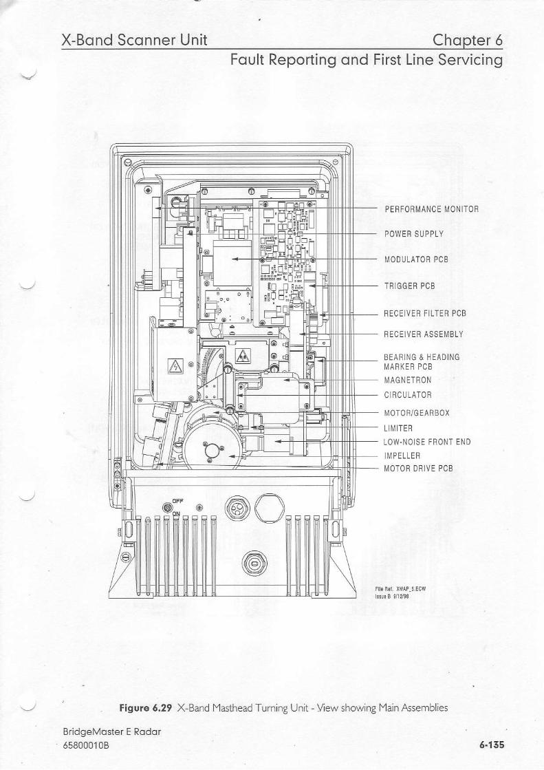
X-Bond Sconner Unit Chopter 5Foult Reporting ond First Line Servicing
PE BFofl [,lANCE [,10N lT0R
P O W E H S U P P L Y
MODULATOR PCB
T R G G E R P C B
BECEIVEN FILTER PCB
RECEIVER ASSEMBLY
BEARING & NEADINGM A R K E B P C B
[/ AGN ETRON
C RCUTATOR
[,IOTOR/GEARBOX
LI[ i ITER
LOW.NOISE FRONT END
M P E L L E RMOTOR DRIVE PCB
tigwe 5.29
BridgeMoster E Rodor658000108
Ps,f-, @O
X-Band l4asthead Turning Unit - Vew showing Main Assemblies
6 .135

Chopter 5 A-bono bconner unr lFoult Finding qnd First Line Servicing
Figuie 6.50 X-BandlYaslhead -Lrni-g Unit - fitnem o'lt/a n Assembles
3 SCFEWS (TnANSCETVER)
2 B O L T S - ] C O N C E A L E D(TRANSCEIVER)PSU TO CASTING
3 S C R E W S ( T R A N S C E I V E R )PSU TO I{ODULATORS U P P O R T P L A T E S
4 S C R E W S . l C O N C E A L E D( T F A N S C E I V E F )[/ ICROWAVE ASS E[,{BLY
4 S C R E W S(l 'TAGNETF0NREPLACEi,IENT)
4 S C R E W S(R EC E]VE RLIMITER TO
REC EIVE H
LOW.N O IS E{ L N F E )
REPLACEMENT)L N F E
FRONT END
BridgeMoster E Rodor658000108
Pt f,, @O
6.126

X-Bond Sconner Unit Chopter 6Foult Reporting ond First Line Servicing
DETAIL OFUPPER TRAN SITION
MOTOR AND GEAFBOX BEARING AND HEADING MARKER PCBA S S E M B L Y
MOTOF D RIVE PCB 8 EAB NG DISK
DETAIL OF LOWERTRANSITION CASTING
PERFORMANCE MONITOB
3 S C F E W S ( D F I V E B E L T N E P L A C E M E N T )WAVEGUIDE TRANSITION
VIEW OF UNDERS DE OF TOP CASTING ASSEMBLY(TRANSCE]VER REMOVED FOR CLARITY)
D RIVE BELT
Figure 6.51 X Band
BridgeMoster E Rodor558000108
lYas -ead -Lrni^g Unit - View inside Lppe' casti-g w .^ Transceive r enoved
DETAIL OF ANTENNA SUPPOHT CAST NG
3 S C R E W S ( M O T O R R E P L A C E M E N I )
6.137

Chopter 6 X-Bond Sconner UnitFoult Finding ond First Line Servicing
Figure 6:52 X-Band lYasthead Turning Unit Side view showing Motor Drive Board retaining screws
BridgeMoster E Rodor6580001086.138

X-Bond Scqnner Unit Chopter 6
TOP CASTING ASSEMELY
Foult Reporting ond First Line Servicing
_-i."1i|3#o'.'COVER
PEFFORi IANCE MONLTO
SHOWN FULLY OPEN
WAVEGUIDE ASSE[,l8LY
MOION DN]VE PCB& SUPPONT CASTING
INPUT BOAFDTOP CASTINC FETAINING BOLTS (4)
MAINS FUSE
/ ' lorro', ISHOWINGLOCKING BOL
SCANNEN STAY SHOWN IN LOCKED POSI] ION
AssEMBLY llii$ iSil^li'*LOWER HOUSING
Figuie 6.55 X Band
BridgeMoster E Rodqr65800010B
Bulkhead Turning Unit - View.showing Main Assemblies
5-129

Chopter 6 X-Bond Sconner UnitFoult Finding ond First Line Servicing
INPUT PCB
Figure 6.54 X-Band Bulkhead Turning Unit - Vew showing assemblies fitted to lower casting.
BridgeMoster E Rqdor658000108
WAVEGUIDE TRANSITION FORBULKHEAD TU BNING UNIT
@ - / - r - T l @L , l t t t r t F r
l - - -_ 1 L l n nf lE fnt r n f n l l uuI t . !
6.140
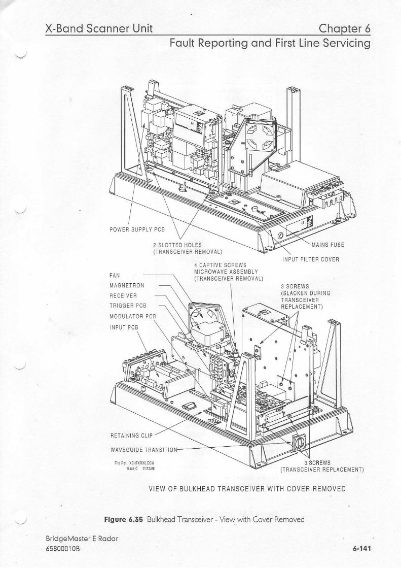
X-Bond Sconner Unit Chopter 6FOUtr KeDOrI tnO OnO FtrSI Ltne Servtctno
POWEF SUPPLY PCB
2 SLOTTED HOLES(TRANSCEIVEB FEl \4OVAL)
M A N S F U S E
3 S C R E W S( S L A C K E N D U R I N GT N A N S C E I V E FR E P L A C E M E N T )
4 C A P T I V E S C B E W Sl\, l lcR0WAVE ASS EM B LY{TEANSCE VER REMOVAT)
M A G N E T B O N
F E C E ] V E F
T R I G G E R P C B
MODUTATOR PCB
LNPUT PCB
RETA N]NG CLIP
W A V E G U L D E T B A N S I T I O
3 SCREWS( T R A N S C E I V E R F E P L A C E M E N T )
VIEW OF BULKHEAD TRANSCEIVER WITH COVER RE[ , IOVED
' Figure 6.55 Bulkhead Transceiver - View with Cover Removed
BridgeMoster E Rodol55800010B
INPUT F LTER COVEF
5.147

Chopter 6 X-Bond Sconner UnitFoult Finding ond First Line Servicing
0n the Trigger PCB set:LKs, and LK6 to 2 - 3.This is lhe service posilion,and will allow lhe transmilterlo transmil when lhe antennais slalionary.
Reslore lhe ship's supplyto lhe Transceiver.Switch on al lhe Displayand wait 3 minules lor timer.Select Long Pulse, Transmital the Display.
0n ihe [4odulator PCB meas!rethe vollage belween TP100 andground.Note:A DVi,l with an input impedancegrealer than 10 l!,{ohms must beused foI this measurement. lJseol a meter wiih lower impedancecould result in damage 1o themagnel ron.
Adjust RV1 on the Power SupplyPCB lo give the same vollage onTP100 as is recorded on lhe labelon the pulse transiormer on thel\.lodulator PCB.
Figure 6.56 Setting Magnetron Current
BridgeMoster E Rqdor658000108
0n complelion ol the procedure.Switch oJl.Reset LK5 and LK6 on lheTrigger PCB to 1 - 2.
6-142
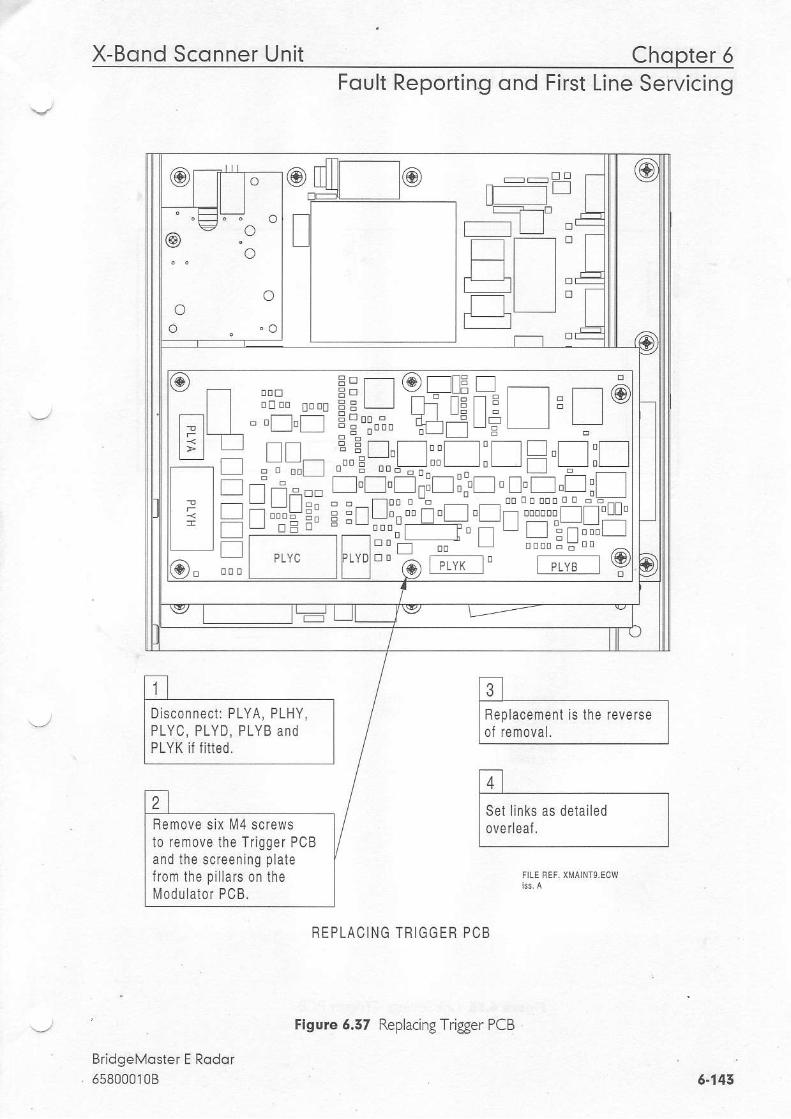
X-Bond Sconner Unit Chopter 5Foult Reporting ond First Line Servicing
R E P L A C I N G T R I G G E R P C B
BridgeMoster E Rqdor658000108
_ _ D t rrr ]......-f l
l o
f t If_ l lr - t l :f t I
t L l- l- E
o
oo
o . o
@o
ft ft
fl1t-', ['l
f tl -i Er E
Hemove six lt l4 screwslo rernove the Trigger PCBand the sc feen ing p la tefrom lhe pil lars on thel\,, lodulator PCB.
f t ,lBeplacement is the reverse II of removal. I
[4-] ,I Set links as delailed II overleaf.
I
6-143
Figure 6.57 Replacing Trigger PCB
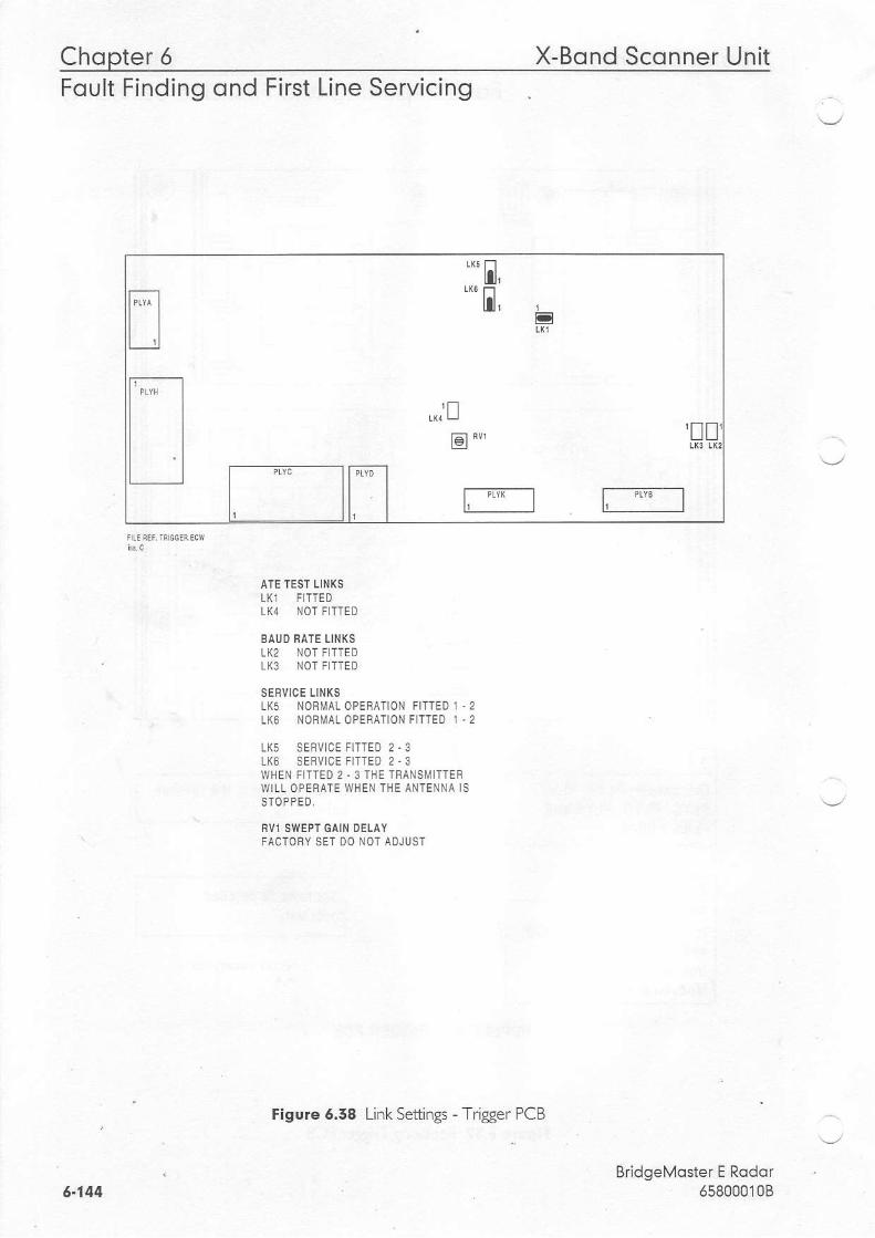
Chqpter 6 X-Bond Sconner UnitFoult Finding ond First Line Servicing
AIE TEST LII{XSLK1 FI-I-IEDL(4 NOT FITTED
BAUD BATE LINKSLK2 NOT FITTEDI.K3 NOT FITTED
SERVICE LINKSLK5 NORMAL OPEEATION FITTED 1 .2LK6 NORMA! OPESATION FITTED 1 .2
LK5 SEqVICE FITTED 2 .3LK6 SERVICE FITTED 2.3WHEN FITTED 2.3 THE TBANSUITTEFWILL OPEBATE WIIEN THE ANTENNA ISSIOPPED,
FVl SWEPT GAIN DELAYFACTORY SET DO NOT ADJUST
Figure 5.58 Link Settings - Trigger PCB
BridgeMqsterE Rqdor6580001085.144

X-Bond Sconner Unit Chopter 5Fcult Reporting ond First Line Servicing
fil ,I To remove lhe ModLr alor PcB Il i l sf tst fecessaryh remNe II the rran$eivs *smbry as II deraied previousy. I
E 'I Bemwe r.iss".. PcB as IIderaiedpreviousry. I
SEPLACLNG MODLJLA]ON PC8
BridgeMoster E Rodqr658000108
t L ] -
r - f---- l Et t I I
t l
@ . "o
Disconnecl ll]Yo magnelron
trl t
10Feplacemenl ls the reverseor renoval. Belore rep acinglhel 99er PCB check lhelink selr ngs on lhe Modulalor
Setlings Modu alor PCB'
Figure 6.59 Replacing f4odulator PCB
6.145

Chopter 5 X-Bond Sconner UnitFoult Finding ond First Line Servicing
tK3 LK2
MoDULAT0R LtNK SETTTNGS F0R 65810812 / 65825812 / 65830812
NOTE THAT LINK 1 ]S CONFIGUNABLE FOR HEATEB TURNDOWN ON 25KW X.BANDNOTE THAT L NKS 2 & 3 ARE HABDW RED FOH SPECIFIC USEAGE.
TEST POINTS:TPlOO MAGNETNON CURRENT MONITOfrTP1Ol CHABGE TBIGGEBTP1O2 MODULATORTBIGGER
BridgeMoster E Rodor658000108
, zwL
E o*
"'h-;fQ )* .;x* r//W
J l f lJJ;r_l
n l H . 'U . r } g
YELLOW
EHT BOARD 6580I816
S.BAND IO KW X.BAND 25 KW X.BANDLKl FIT1ED 2 .3 FITTED 1 .2 F]TTED I .2 FOF MAGNETHON MG5424
LK1 FITTED 2.3 FOR MAGNETRON M1458
LK2 FiTTED NOT FITTED NOT F]TTEDLK3 NOT FITTED FITTED NOT F TTED
6.146
Figuie 5.40 Link Settings - lYodulatorPCB

X-Bond Sconner Unit Chopter 6Foult Reporting ond First Line Servicing
frtSel i in[s as delai led in'Link Sel l ing PSU PcB' I
trtI Alle' rep acins lhe Pol{e' II Suppy PCB lt s necessary || 1o sellhe Masnelron curenl II as deiailed in'sefiins II Masnetron c!fianr' I EEPLACING THE X.BAND PSU
Figure 6.41 Replacing PSU PCB
Bridgel'loster E Rodor65800010B
WABNINGIBefore slaning lhis procedure ensurelhat 031 is nol lllumlnated.lf D3l is llluminated lsolate Trinsceiverirom ship's mains supply belorcproceeding.
\9r---r f_l
\ f l\ l
\ ldh"\ oEo l l \- - N
l"+ |_ - f- - l
@ l- - !-- l j l
, l l l l Lleql/--\ lI r f L / \ /' n { ) \ /
t-/ \ / '+'
l t t . + t l IoL--,-l -.E I
r ' r ' i - =t . _ @L t t t _
c- lfl n/--\n. trLl Ll\ )
_ l ur^oL lUd[o_ (J-o
f)ElIq PIIN llllEl ' PLTA
securjng heahink lo chassls.
NOTE: o o oo o
o
o o
6.147
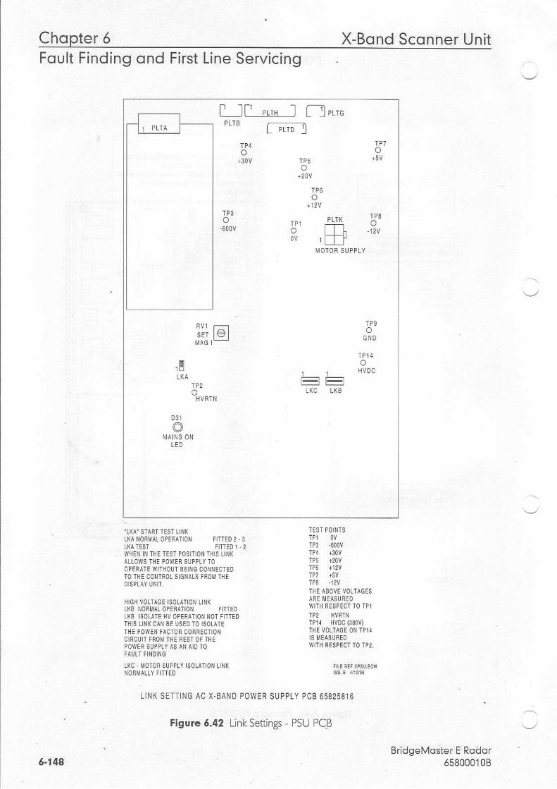
Chopter 6 X-Bond Sconner Unit
t_JPLTS
[, 'rr" I fl"'u-PLrD I
oo
o
o
o P L T K A 'o l l h . 1 2 . | /o v r l l l
sET le
tl
o
D31
MAINS ONLED
1
LKC
1
Lt(s
oG N D
o11V0C
Foult Finding ond First Line Servicing
.LKA. START TEST L NK TESI Po|N'ISLKA NoBMALoPERAToN f lTTED2,3 TP1 ov$TEST FTTTED 1- 2 TP3 .600V
WHEN lN THETEST POS|TION TH|S LINK TP4 130VALLoWSTHE POWER SUppLyTO TP5 +20VOPEnATE W|THOLJTBetNG CONNECTED TP6 rl2vTO TflE CONTROL StcNAtS FROII THE rp7 +5vDSpLAy UN|T. TPg l2V
HIGH volr^cF rsoLATroN L NK 1,1-i M"Ei"s"ul1D,^ -"-L(B NOBMALOPERATIONtKg SotArE HV OPEBAT|ON NOTFTTEO TP2 HVRII{lHtS LTNKCAN BE USEDTO tsOtATE IPll HVDC(330V)THE pOwEB FACTOR COnBECTTON THEVoLTACE ONTP14cIRcUIT F f ,oMTHEnEsToFTHE S MEASUREDPOWEBSUPPLY AS AN AIDIO r/lITIl FESPECTT0'IP2
LKC- M0T0F SUPPLY ISoLATIoN llNK nc*FFsuEcwNOf,I,IATLY FITTIO
LINK SETTINC AC X.BAND POWER SUPPLY PCB 65825816
BridgeMoster E Rodor6580001085.144
Figvre 6.42 Linl, Setfings DSU DCB
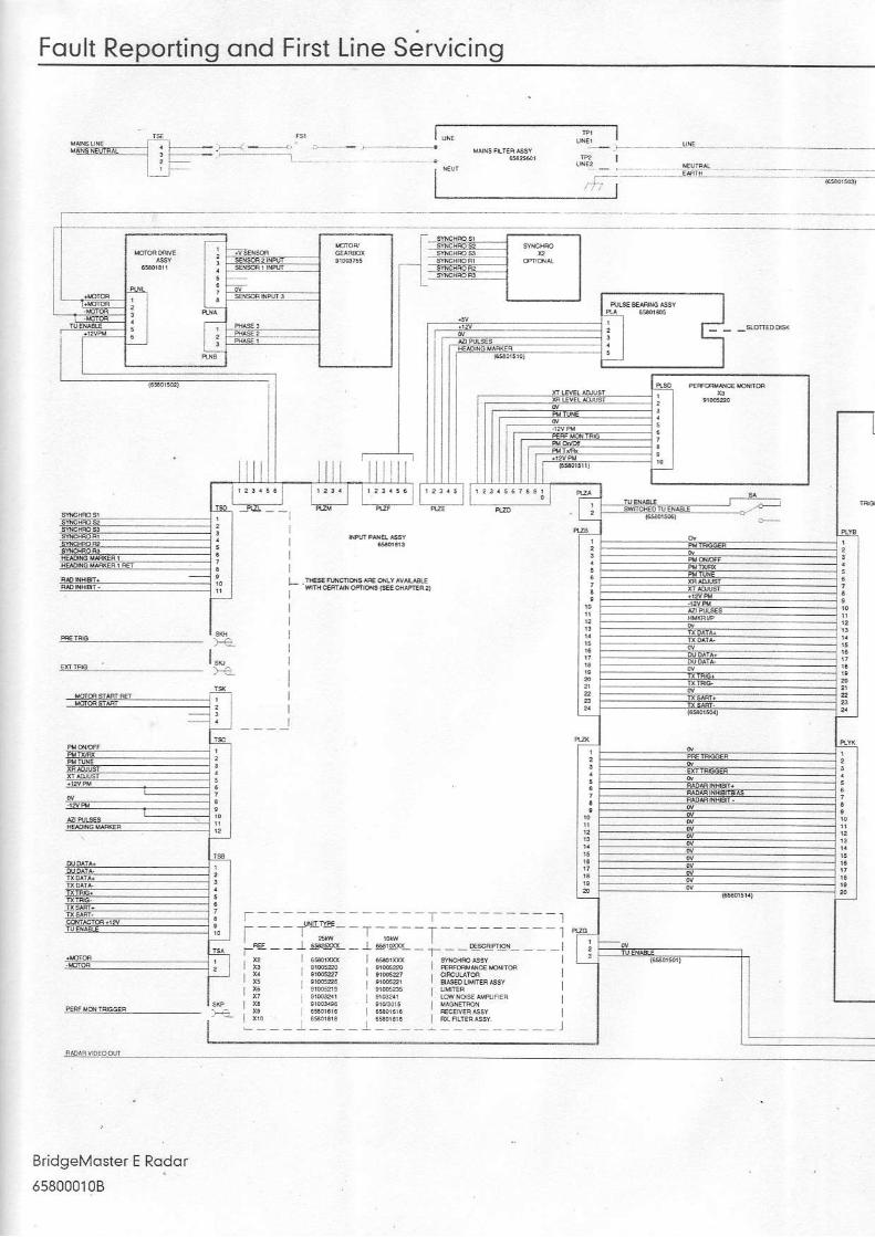
Foult Reporting ond First Line Servicing
F -q!cisos,-,,-l-_-__--_]
I r'----- - l I
l -1 t ; - + _ @t l f f i -
f - - - - ; ; - - - - r - - - - rr_ l ;_ ' t ; . -r-- --1
I s!;o I q;s6_ - j
BridgeMoster E Rador
658000108
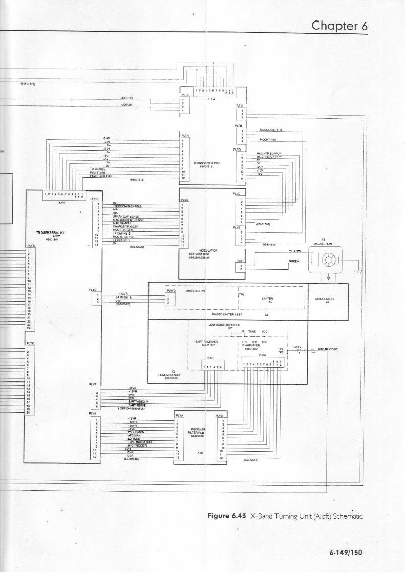
Chqpter 5
-ni l
l
l $
l l
i " " * *_ _ _ _ T ! _ - , l
Figure 6.45 X-Band Turning Unit (Aloft) khematic
5.1491150
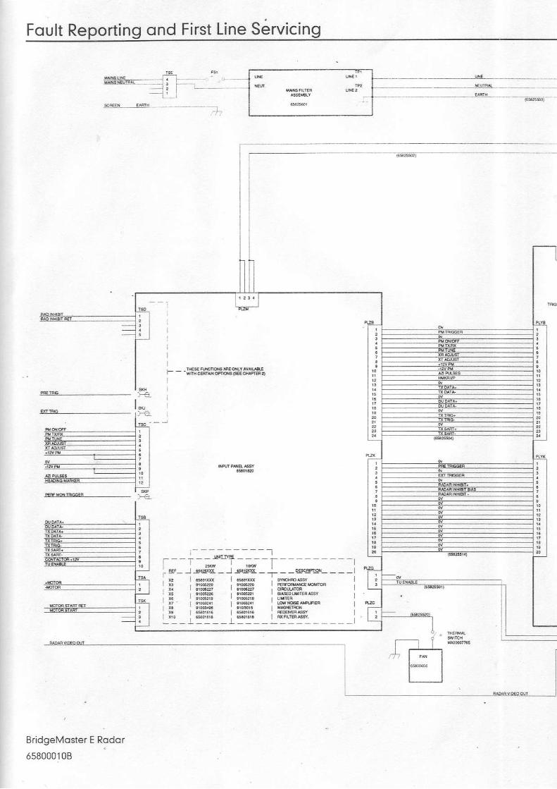
Foult Reporting ond First Line Servicing
_t .
al' r
EridgeMoster E Rodor
658000108
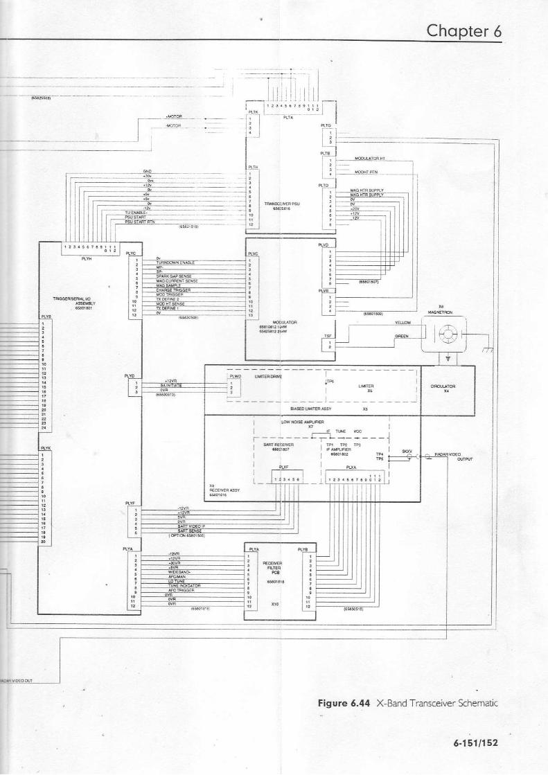
Chopter 6
| '' l 'i
- l
iil i l
I, !-i
l
i +
I
l
;
] s E ! ? J u iI .--r, * E ;r : ] : - - - _ r - ] . j
Figure 6.44 X Band Transceiver Schematlc
6-1511152

Fqult Reporting ond First Line Servicing
L_ E@E*YAngl
BridgeMoster E Rodqr
658000108
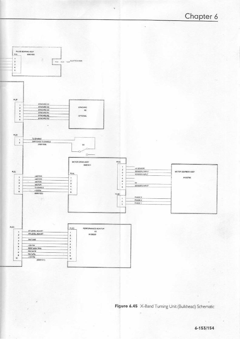
Chopter 6 .
X-Band Tuming Unrt (Bulkhead) khemdic
5.7551194
Figure 6.45
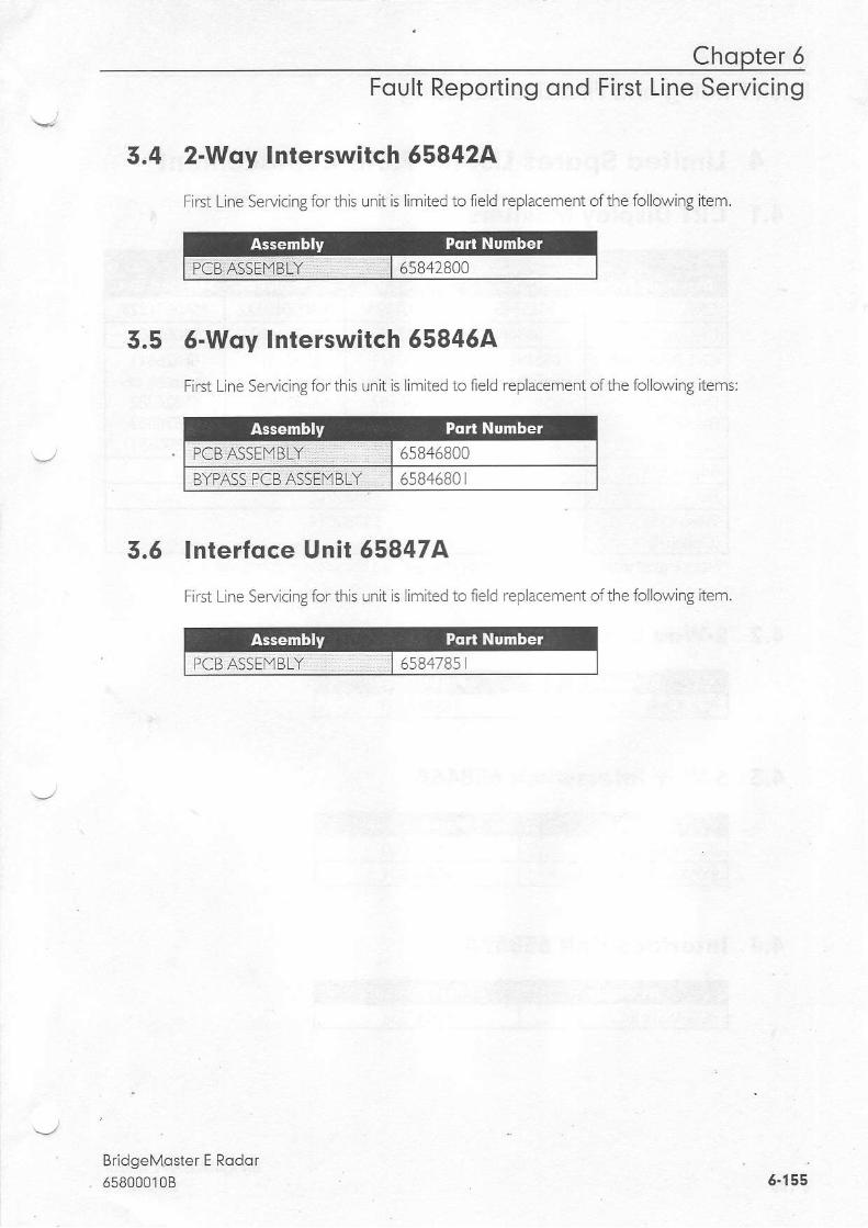
Chopter 6Foult Reporting ond First Line Servicing
3.4 2-Way Interswitch 658424
First Line Servic ng for th s unit is imited to feld replacement ofthe following item.
5.5 6-Woy Interswitch 65846A
First Line SeMcing for this un t is I mited to ield replacement ofthe fo low ng items:
3.5 lnterfoce Unir 558474
First L ne Seryiclng for thls unit is irn ted to ie d replacement ofthe following item.
BridgeMoster E Rodor6s8000108 6-155
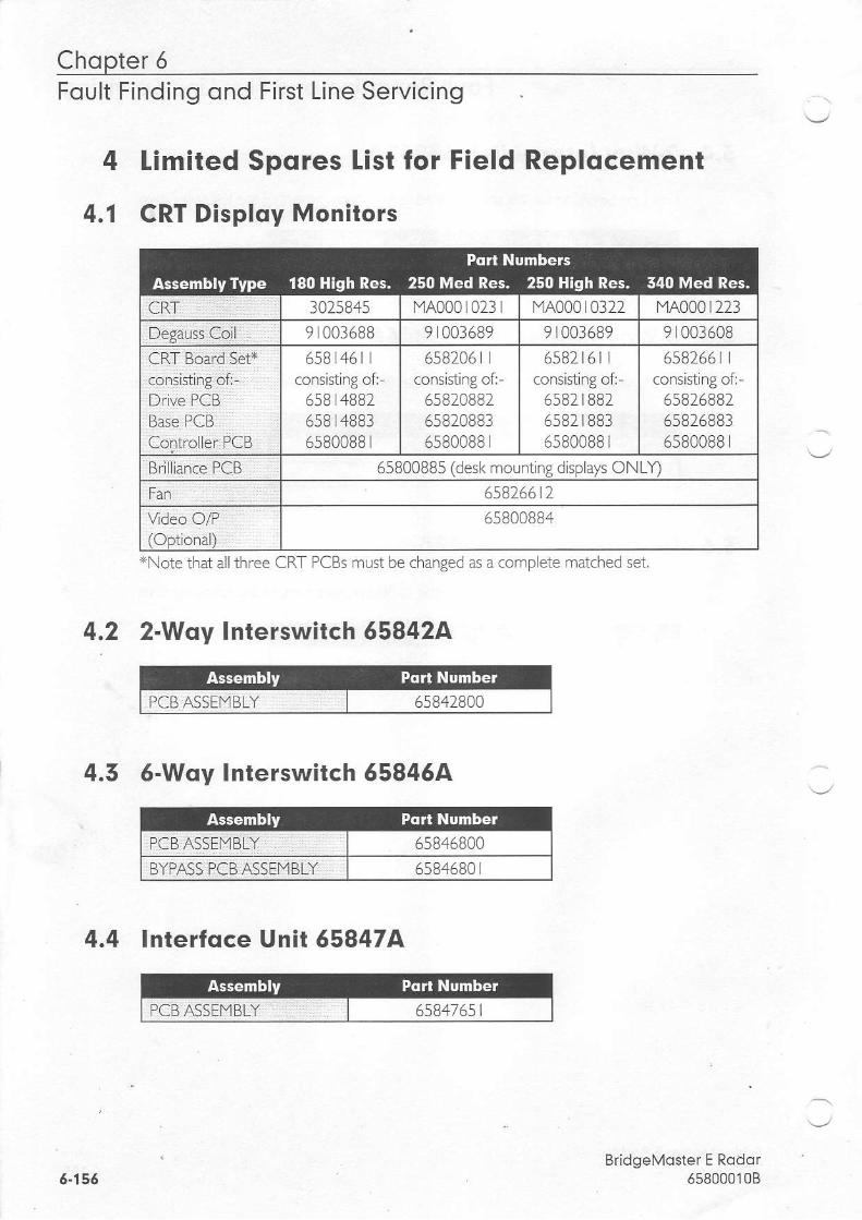
Chopter 5Foult Finding ond First Line Servicing
4 [imited Spores list for Field Replocement
4.1 CRT Disploy Monitors
4.2 2-Woy Interswitch 658424
4.5 6-Woy Inlerswitch 658464
4.4 lnterfoce Unit 658474
BridgeMoster E Rodor658000108
3025845 MA000 L02t I f iA00010322
9 003688 9 1003689 9 001689 9 003608658205 I
consisting of:65820882658208836s800BB I
558)t6lconsistrng of:
5582 | 8825582 tB8365BOOBB
658)661consisting of-
558268825582588365BOOBB
CRT Board Set+
Drive PCBBase PCBController PCB
658 461consisting of:
658 4BB2658 4BB35s80088 t
Brll iance PCB 65800885 de-l roun. ng di:pla,, ON 'l
6582661765800884Video O,/P
xNote that allthree CRT PCBs must be chaneed as a complete matched set
6-156

Chopter 6Foult Reporting ond First Line Servicing
4.5 S-Bond Turning Units (Mostheqd ond Bulkheod)
.DICCER OCB ASSEYBLY 5580 B06580 8045580 B 145s80r8096580i8056580 IB B
RFCFIVF_R AqSF_MRIY 658306 6658108 2914052249 r0052259 t005223
PERFORI4ANCE.T,lQNITOR 9 t403746|1OTOR 220240VAND 380/440V 3PH Norma Speed 9 r00375 |
9 t003752IYOIOR 220240V AND 380/440V 3PH High Speed 9 r003753
9 043154
9 AA522BFUSE tYA00007245
65830656THERI"IAL SWITCH (FOR FAN - I'aASTHEAD Tx/Rx) tYAo0007765
Br;dgeMoster E Rodor6s8000108 6.157

Chopter 6Foult Finding ond First Line Servicing
4.6 X.Bqnd Turning Units (Moslheod ond Bulkheod)(1OkW & 25kW Units)
6580 B0T D I C C E P D C B A S S - M B - \ r J \ l l > c N D N C NSL- I . ,
,Pl 6580 r822
]NPUT PCB ASSEt,lBLY flURN NG UNIT) 6580 r8 r36s80 r820558258 t55580 | 805
6 5 8 0 t 8 1 8
RECE VER ASSEIYBLY] 6 5 8 0 t 6 1 6658 08 t2
Lrfl TER ASSE f,tB LY ( r 0k\ 4 9 t40522T"TAGNETRON ( r0k\9 9 r0030 r5MODUTATOR PCB ASSEI'1BLY (25KV\4 (SIANDARD) 658258 t2I']ODUIATOR PCB ASSEI'1BLY (25KW (UN TSEND]NG IN 'P' SUFFIX)
658258 t3
Lt[1]TER ASSEtlBLY (25kW) 9 005226r'fAGNETRON (25kW 9 403496
CIRCU LATOR 9 4052279 4052246580 r8 r I
IYOIOR & GLARBOX ASSE]YBLY. 9 443765II"lPELLER 6580 | l5
IV]A NS FILTER PCB ASSEI"]BLY 6582560 |FUSE 1"1A00007245
r"rA00008979FAN AXIAL 80r80x25 24VDC (BULKHEAD Tx/Rx) 65830656THERIjAL SWITC| (FOR FAN BULKHEAD TxlRx) yA00007765
6580 506
BridgeMosier E Rodor6580001086"158
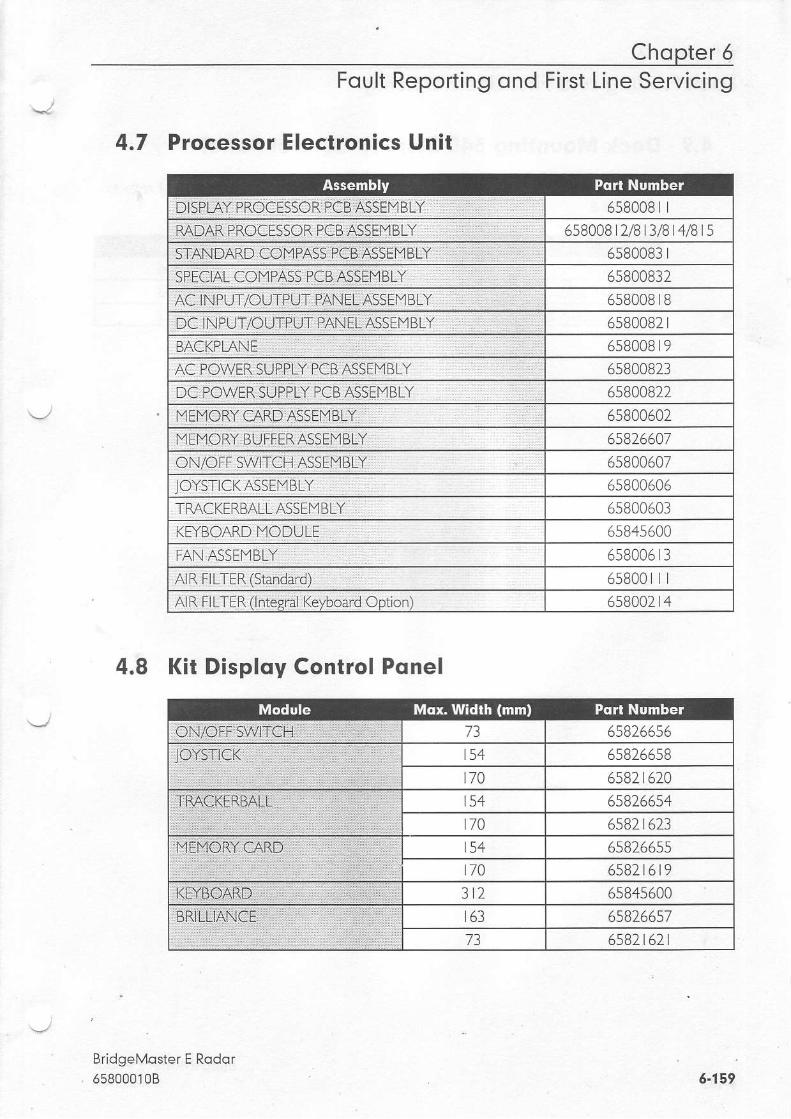
Chopter 6Foult Reporting ond First Line Servicing
4.7 Processor Electronics Unit
658008 |658008 2/B 3/B 4/B rs
6s8008365800832658008 tB6580082 r6s8008 r96s800823
F,ra pn\^/FF <r rppl v paa a<<FMR / 65800822
I,]EI]ORY CARDASSEIY BLY 6580060265D660165800607o580000o
TP'ACKERBALL ASSEIYBLY 65800601KFTBOARD I.lODULE 6584s600FAN ASSE]YBLY 658006 r3
65800 |AIR FILTER (lntesral Keyboard Optlon) 658002 t,1
4.8 Ki t Disploy Contro l Ponel
BridgeMoster E Rodor658000108

Chopter 5Foult Finding ond First Line Servicing
4.9 Deck Mounting 540 Disploy Control Pqnel
NoIe - For units f,tted wrth exL.uded panel (as shown at Fbure 6.2 in this chapter), refer toSectron 4. L
BridgeMoster E Rodor6580001086-160