Embed Size (px)
Citation preview

Rad-87™
Signal Extraction Pulse CO-Oximeter
Service Manual

ii Rad-87 Signal Extraction Pulse CO-Oximeter Service Manual
Rad-87™
Signal Extraction Pulse CO-Oximeter
Service Manual

Rad-87 Signal Extraction Pulse CO-Oximeter Service Manual iii
The Rad-87 Pulse CO-Oximeter Service Manual is intended to provide the necessary information for proper servicing of all models of the Rad-87 Pulse CO-Oximetry systems. This manual is structured to support troubleshooting to the assembly or module level. This manual does not provide instructions for troubleshooting to the printed circuit board component level. There may be information provided in this manual that is not relevant for your system. Do not service the Rad-87 Pulse CO-Oximeter without completely reading and understanding these instructions. NOTICE: Purchase or possession of this device does not carry any express or implied license to use this device with replacement parts which would, alone or in combination with this device, fall within the scope of one of the patents relating to this device. CAUTION: Federal law (U.S.) restricts this device to sale by or on the order of a physician.
Masimo Corporation 40 Parker
Irvine, CA 92618 USA
Tel.: 949-297-7000 Fax.: 949-297-7001 www.masimo.com
EU Authorized Representative for Masimo Corporation:
EC REP MDSS GmbH Schiffgraben 41
30175 Hannover, Germany Tel.: +49-511-62 62 86 30 Fax.: +49-511-62 62 86 33
CONFORMS TO UL STD 60601-1 AND CERTIFIED TO CAN/CSA STD C22.2 NO. 601.1 Covered by one or more of the following U.S patents: 5482036, 5490505, 5632272, 5685299, 5758644, 5769785, 5919134, 6002952, 6011986, 6067462, 6157850, 6229856, 6236872, 6263222, 6360114, 6388240, 6430525, 6463311, 6501975, 6515273, 6606511, 6643530, 6650917, 6654624, 6661161, 6684090, 6699194, 6745060, 6816741, 6826419, 6850787, 6861639, 6979812, 7186966, 7215984, 7215986, 7221971, 7254433, 7295866, 7328053, 7373194, 7376453, 7377899, 7467002, 7469157, 7471969, 7489958, 7496393, 7499741, 7509154, 7530955, RE38476, RE38492, international equivalents, or one or more of the patents referenced at www.masimo.com/patents. Other patents pending. © 2010 Masimo Corporation. LNCS, Masimo, MX-1, PVI, Rad, the Radical logo, Rainbow, Satshare, SET, Signal I.Q., SpCO, and SpMet are federally registered trademarks of Masimo Corporation. APOD, Pulse CO-Oximeter, Pulse CO-Oximetry and Rad 87 are trademarks of Masimo Corporation.

iv Rad-87 Signal Extraction Pulse CO-Oximeter Service Manual
Table of Contents Page
1 Overview ........................................... .............................................1-1 1.1 About this Manual .....................................................................1-1 1.2 Warnings, Cautions and Notes.................................................1-1
2 Maintenance ........................................ ..........................................2-1 2.1 Introduction ...............................................................................2-1 2.2 Cleaning....................................................................................2-1
3 Battery Operation and Maintenance .................. .........................3-1 3.1 Overview...................................................................................3-1 3.2 Replacing the Battery ...............................................................3-1
4 Performance Verification ........................... ..................................4-1 4.1 Overview...................................................................................4-1 4.2 Power-On Self-Test ..................................................................4-1 4.3 Key Press Button Test..............................................................4-1 4.4 Alarm Suspend Indicator ..........................................................4-1 4.5 Alarm Volume Test ...................................................................4-1 4.6 Alarm Limit Test........................................................................4-2 4.7 Sensitivity Mode Test ...............................................................4-2 4.8 Button Volume Test ..................................................................4-2 4.9 Brightness Test.........................................................................4-3 4.10 Testing with Masimo Rainbow SET Tester ..............................4-3 4.11 PVI (Pleth Variability Index) Testing (If Applicable)..................4-4 4.12 Wireless Radio Testing (If Applicable)......................................4-4 4.13 Serial Port .................................................................................4-4 4.14 Nurse Call Test .........................................................................4-5
5 Electrical Safety Tests............................ ......................................5-1 5.1 Test Equipment.........................................................................5-1 5.2 Ground Wire Leakage Current Tests .......................................5-1 5.3 Enclosure Leakage Current Tests............................................5-2 5.4 Source Leakage Current Tests.................................................5-3
6 Repair ............................................. ................................................6-1 6.1 Safety Precautions: ..................................................................6-1 6.2 General Procedures .................................................................6-1 6.3 Troubleshooting ........................................................................6-2 6.4 Service Messages: ...................................................................6-3
7 Returns............................................ ...............................................7-1 7.1 Product Decontamination .........................................................7-1 7.2 Return Transportation...............................................................7-1
8 Drawings and Schematics ............................ ...............................8-1

Rad-87 Signal Extraction Pulse CO-Oximeter Service Manual v


Rad-87 Signal Extraction Pulse CO-Oximeter Service Manual 1-1
1 Overview
1.1 About this Manual This manual explains how to service the Rad-87 Pulse CO-Oximeter. Important safety information relating to general use of the Rad-87 Pulse CO-Oximeter appears in the Rad-87 CO-Oximeter Operator’s Manual. Other important safety information is located throughout this manual where appropriate.
1.2 Warnings, Cautions and Notes Please read and follow any warnings, cautions and notes presented throughout this manual. An explanation of these labels is as follows: A WARNING is provided when actions may result in a serious outcome (i.e., injury, serious adverse affect, or death) to the patient or user. Look for text in a gray shaded box. Sample of WARNING:
WARNING: THIS IS A SAMPLE OF A WARNING STATEMENT.
A CAUTION is given when any special care is to be exercised by the patient or user to avoid injury to the patient, damage to this device or damage to other property. Sample of Caution:
CAUTION: This is a sample of a Caution statement. A NOTE is provided when extra general information is applicable. Sample of NOTE:
NOTE: This is a sample of a NOTE statement.


Rad-87 Signal Extraction Pulse CO-Oximeter Service Manual 2-1
2 Maintenance
2.1 Introduction
2.1.1 This chapter covers how to test the operation of the Rad-87 and SatShare interface (if applicable), how to properly clean the Rad-87 Pulse CO-Oximeter, how to recharge and replace the batteries, how to replace the fuses, and how to obtain service under normal operation. No internal adjustment or recalibration is required. Service should be performed by qualified personnel only. Safety checks should be performed at regular intervals or in accordance with local and governmental regulations.
Note: Opening or repairing the Rad-8 Pulse Oximeter will void the Masimo warranty. Products that require repair while under warranty should always be returned to Masimo for warranty service.
WARNING: ELECTRICAL SHOCK AND FLAMMABILITY HAZARD.
BEFORE CLEANING THE PULSE CO-OXIMETER, ALWAYS
TURN THE UNIT OFF AND DISCONNECT THE POWER
CORD FROM THE BACK OF THE UNIT.
2.2 Cleaning
2.2.1 To clean the display panel use a cotton swab moistened with 70% isopropyl alcohol and gently wipe the panel.
2.2.2 To clean the outer surface of the Pulse CO-Oximeter, use a soft cloth moistened with a 70% isopropyl alcohol. Do not allow liquids to enter the interior of the instrument.
2.2.3 To decontaminate unit, refer to Section 6.
CAUTIONS:
• Do not autoclave, pressure sterilize, or gas sterilize this Pulse CO-Oximeter.
• Do not soak or immerse the monitor in any liquid.
• Use the cleaning solution sparingly. Allow unit to air dry. Excessive solution can flow into the monitor and cause damage to internal components.
• Do not touch, press, or rub the display panels with abrasive cleaning compounds, instruments, brushes, rough-surface materials, or bring them into contact with anything that could scratch the panel.

2-2 Rad-87 Signal Extraction Pulse CO-Oximeter Service Manual
• Do not use petroleum-based or acetone solutions, or other harsh solvents, to clean the Pulse CO-Oximeter. These substances attack the instrument’s materials and instrument failure can result.

Rad-87 Signal Extraction Pulse CO-Oximeter Service Manual 3-1
3 Battery Operation and Maintenance
3.1 Overview
3.1.1 The Rad-87 Pulse CO-Oximeter uses a 6 volt, 1.4AHr lead acid, sealed, rechargeable battery.
3.1.2 Please reference the Rad-87 Operator’s Manual for specifications on battery charge time and capacity.
CAUTIONS:
• If the Rad-87 has not been charged for 1 month or more, then recharge the battery prior to use.
• At low battery warning, connect the Rad-87 to AC power to prevent interruption of power.
• Additional information on the Rad-87 batteries may be found in the Rad-87 Operators Manual.
3.2 Replacing the Battery
3.2.1 Turn the Rad-87 off and remove the patient cable connection.
3.2.2 Place the unit on its side with the rubber footings facing up.
3.2.3 Remove the four screws from the housing assembly.
3.2.4 Carefully remove the speaker-side housing assembly. DO NOT pull housing away as it may damage the speaker cabl e.
3.2.5 Remove the speaker connector from the system board and set the housing aside.
3.2.6 Carefully lift the battery out of the housing and remove the positive and negative battery connections.
3.2.7 Install the replacement battery. Verify proper positioning of the (+) positive and (-) negative connectors. Reverse steps 3..3.1 through 3.3.6 to reassemble.
3.2.8 Verify the unit turns on, that all the LEDs momentarily light (AC LED will not illuminate when powering on with battery power only), that the low battery LED is not illuminated, and that the unit stabilizes to a normal operation mode.
CAUTION: Follow local governing guidelines for proper disposal of the internal battery. Do not incinerate.

3-2 Rad-87 Signal Extraction Pulse CO-Oximeter Service Manual
CAUTION: Do not over-tighten screws. Tighten the screws throughout the Rad-87 to 80 in.- oz.
NOTE: It will be necessary to perform safety testing after replacement. Refer to section 5.

Rad-87 Signal Extraction Pulse CO-Oximeter Service Manual 4-1
4 Performance Verification
NOTE: Under normal operation, no internal adjustment or recalibration is required.
4.1 Overview
4.1.1 To test the performance of the Rad-87 Pulse CO-Oximeter following repairs or during routine maintenance, follow the procedure outlined in this section. If the Rad-87 fails any of the described tests, discontinue its use and correct the problem before returning the unit back to the user.
4.2 Power-On Self-Test
4.2.1 With the Rad-87 plugged into an AC power source and no cable or sensor plugged into the instrument, turn the monitor on by depressing the Power Button. For about 2 seconds all available LEDs are illuminated and a brief beep tone sounds. The unit will then cycle through Saturation and Pulse Rate alarm limits on the top LCD.
4.2.2 After this initialization “boot” cycle, the No Sensor, Alarm Suspend and Normal Sensitivity Mode LED indicators will light. Also, the SpO2 and BPM monitoring display will indicate “---“. The Rad-87 is ready to begin normal operation.
4.2.3 Turn power off and then back on as many times as necessary to verify this Power-On cycle.
4.3 Key Press Button Test
4.3.1 With the exception of the Power/Standby Button, press each soft key button and verify that the Rad-87 acknowledges each key-press with an audible beep tone or by indicating an associated change on the display.
4.4 Alarm Suspend Indicator
4.4.1 Induce an alarm condition.
4.4.2 Press the Alarm Suspend button and cycle through the 2 different indicator levels: the red indicator blinks red when an alarm condition is met. The yellow indicator will blink on when the alarms have been suspended.
4.5 Alarm Volume Test
4.5.1 Press the Enter button. Monitor displays should show “AL” and “VOL”.

4-2 Rad-87 Signal Extraction Pulse CO-Oximeter Service Manual
4.5.2 Press the UP arrow button and cycle through the three different volume levels. Make sure the tone does not have a harsh or raspy tone due to the speaker rattling in the plastic housing. The tone heard should be louder with each press. Press the DOWN arrow button and cycle through the different volume levels. The tone heard should be quieter with each press. Verify both speakers are working.
4.5.3 Return the volume to the factory default level 3.
4.6 Alarm Limit Test
4.6.1 With the monitor turned on, depress the ALARM LIMITS button and enter alarm menu. Change the High Saturation Alarm parameter to a value two points below the currently selected value, and accept the change by pressing the Enter button.
4.6.2 Verify that the newly set parameter is shown on the Saturation Alarm Limit Display.
4.6.3 Return the High Saturation Alarm parameter to its original setting and accept the change by pressing the Enter button.
4.6.4 Repeat steps 4.6.1 to 4.6.3 with the Low Saturation Alarm parameter.
4.6.5 Repeat steps 4.6.1 to 4.6.3 with the Low and High Pulse Rate Alarm parameter.
4.6.6 Reset the alarm limits again to the original settings and accept the changes by pressing the Enter button.
4.7 Sensitivity Mode Test
4.7.1 Press the Sensitivity button to alternately light the APOD, NORM, and MAX LEDs.
4.8 Button Volume Test
4.8.1 Press the Enter button x5. LED displays should show “but”, and “VOL”.
4.8.2 Press the Up arrow button and cycle through the different volume levels. Make sure the tone does not have a harsh or raspy tone due to the speaker rattling in the plastic housing. The tone heard should be louder with each press. Press the DOWN arrow button and cycle through the different volume levels. The tone heard should be quieter with each press. There are three volume levels and volume off.
4.8.3 Return the volume to the factory default level 2.

Rad-87 Signal Extraction Pulse CO-Oximeter Service Manual 4-3
4.9 Brightness Test
4.9.1 Press the Display Brightness button. LED displays should show “dlS” above and “brt” below.
4.9.2 Press the Display Brightness button and cycle through the different brightness levels. There are four brightness levels. Factory default is level 2.
4.9.3 Press the Enter button to return to patient monitoring mode or wait for display to time out.
4.10 Testing with Masimo Rainbow SET Tester
4.10.1 Turn the Rad-87 off and then on again.
4.10.2 Set the alarm limits to:
% SpO2 Pulse Rate % SpCO % SpMet
High 100 140 10 3
Low 90 50 -- --
4.10.3 Connect the Masimo tester to the Rad-87 (PN 2386). (See Tester DFU for complete instructions.)
4.10.4 Verify that within 20 seconds a Signal I.Q. Bar Graph and SpO2
& Pulse Rate numbers display.
4.10.5 Verify that the SpO2 measurement is between 78% and 84%. (with tester values of 81% +/- 3%)
4.10.6 Verify that the pulse rate measurement is between 60 bpm and 62 bpm (with tester values of 61 +/- 1 bpm).
4.10.7 Verify that the SpCO measurement is between 4% and 10%. (with tester values of 7% +/- 3%)
4.10.8 Verify that the SpMet measurement is between 2.4% and 4.4%. (with tester values of 3.4% +/- 1%)
4.10.9 Verify that an audible alarm occurs and that the SpO2 measurement and the low SpO2 alarm limit display are flashing
4.10.10 Press the Alarm Silence button once and verify that the alarm is silenced.
4.10.11 Wait 120 seconds and verify that the alarm silence times out and the audible alarm is activated again. Disable the Alarm before continuing.

4-4 Rad-87 Signal Extraction Pulse CO-Oximeter Service Manual
4.10.12 Press the Up Arrow button several times and verify that the loudness of the pulse beep tone increases.
4.10.13 Press the Down Arrow button and verify that the loudness of the pulse beep tone decreases. Press the Down Arrow button and verify that the loudness of the pulse beep tone can be turned off.
4.11 PVI (Pleth Variability Index) Testing (If Appl icable)
NOTE: THIS IS PERFORMED AS A FUNCTIONAL TEST ONLY.
4.11.1 Connect a Red Masimo SET Rainbow sensor to the Rad-87 Handheld.
4.11.2 Insert the non-dominant hand’s ring finger into the finger sensor.
4.11.3 PVI will fluctuate depending on motion, perfusion, physiology and other factors, so there is no ‘normal’ value. If a number is displayed, then the PVI feature is functioning properly.
4.12 Wireless Radio Testing (If Applicable)
4.12.1 Press and hold the Brightness button and the Down button for 5 seconds.
4.12.2 Use the Up and Down arrows to turn the wireless radio on.
4.12.3 When the radio feature is enabled and configured with the network information, the LCD display will show the SSID, IP Address, Subnet, Gateway, MAC Address, and Signal Strength for 20 seconds.
4.13 Serial Port
4.13.1 The serial port outputs ASCII data using standard RS-232 protocol via a straight through serial cable.
4.13.2 Validation of the port can be done by connecting a serial printer or using a PC with Hyper Terminal and the following setup:
4.13.3 Communication Parameters
baud rate 9600 bps data bits 8 stop bit 1 parity none
hand shaking none

Rad-87 Signal Extraction Pulse CO-Oximeter Service Manual 4-5
4.13.4 With the Rad-87 connected as per the above setup, attach a patient cable and sensor to the Rad-87. From the Output menu, select ASCII 1 and the printer (or PC monitor) will print in the following format every second:
05/15/10 08:12:21 SN=0000070986 SPO2=---% BPM=--- PI=--.--% SPCO=--.-% SPMET=--.-% DESAT=-- PIDELTA=+-- PVI=--- ALARM=0000 EXC=000000
4.14 Nurse Call Test
4.14.1 Disconnect the patient cable or the Masimo SET Tester from the monitor and turn the instrument on. Ensure that there are no audible alarms and that the audible alarms are not silenced.
4.14.2 Connect the common lead of a digital multi-meter to the tip (Nurse Call - Common) of the Nurse Call Connector.
4.14.3 Connect the positive lead of the multi-meter to the sleeve (Nurse Call - Normally Open) of the Nurse Call Connector and measure that the resistance is greater than 1 M Ohm (open circuit).
4.14.4 Trigger an alarm on the monitor (e.g. by disconnecting a sensor after it has started measuring data) and verify the resistance is < 20 Ohm.


Rad-87 Signal Extraction Pulse CO-Oximeter Service Manual 5-1
5 Electrical Safety Tests Masimo recommends that you perform all safety tests presented in this section. • Upon receipt of the device • Each time the main enclosure is disassembled or a c ircuit
board is removed, repaired, tested, or replaced.
5.1 Test Equipment The recommended test equipment required to perform electrical safety tests is listed below.
Fluke 180 Electrical Safety Analyzer or compatible.
5.2 Ground Wire Leakage Current Tests
Leakage-HI: 300.00 uA
Leakage-LO: 0.00 uA
Voltage HI: 120.0V
Voltage LO: 100.0V
Probe: Ground To Line
Neutral : Closed
Reverse: Off Ground: Open
5.2.1 Connect the power cord of the monitor to the power receptacle on the leakage tester.
5.2.2 Turn the monitor being tested ON.
5.2.3 Read the current leakage on the Electrical Safety Analyzer.
5.2.4 Set the polarity on the Electrical Safety Analyzer to Reverse.
Leakage-HI: 300.00 uA
Leakage-LO: 0.00 uA
Voltage HI: 120.0V
Voltage LO: 100.0V
Probe: Ground To Line
Neutral : Closed
Reverse: On Ground: Open
5.2.5 Read the current leakage on the Electrical Safety Analyzer.
NOTE: The readings should not exceed 300 µA or 0.3 volts at 100-120V
/50-60Hz on the Electrical Safety Analyzer with the monitor powered on.
5.2.6 Turn the monitor off.

5-2 Rad-87 Signal Extraction Pulse CO-Oximeter Service Manual
5.3 Enclosure Leakage Current Tests
Leakage-HI: 300.00 uA
Leakage-LO: 0.00 uA
Voltage HI: 120.0V
Voltage LO: 100.0V
Probe: Ground To Line
Neutral : Closed
Reverse: Off Ground: Open
5.3.1 Connect the probe of the Electrical Safety Analyzer to the Equipotential lug on the back of the monitor.
5.3.2 Set the Ground switch to the Open position on the Electrical Safety Analyzer.
5.3.3 Turn the monitor on.
5.3.4 Read the current leakage on the Electrical Safety Analyzer.
5.3.5 Set the polarity on the Electrical Safety Analyzer to Reverse.
5.3.6 Read the current leakage on the Electrical Safety Analyzer.
NOTE: The readings should not exceed 300 µA or 0.3 volts at 100-120V
/50-60Hz on the Electrical Safety Analyzer with the monitor powered on.
Leakage-HI: 100.00 uA
Leakage-LO: 0.00 uA
Voltage HI: 120.0V
Voltage LO: 100.0V
Probe: Ground To Line
Neutral : Closed
Reverse: Off Ground: Closed
5.3.7 Set the Ground switch to the Closed position on the Electrical Safety Analyzer.
5.3.8 Read the current leakage on the Electrical Safety Analyzer.
5.3.9 Set the polarity on the Electrical Safety Analyzer to Reverse.
5.3.10 Read the current leakage on the Electrical Safety Analyzer.
NOTE: The readings should not exceed 100 µA or 0.1 volts at 100-120V
/50-60Hz on the Electrical Safety Analyzer with the monitor powered on.
5.3.11 Turn the Monitor off.

Rad-87 Signal Extraction Pulse CO-Oximeter Service Manual 5-3
5.4 Source Leakage Current Tests
Leakage-HI: 100.00 uA
Leakage-LO: 0.00 uA
Voltage HI: 120.0V
Voltage LO: 100.0V
Probe: High To Line
Neutral : Closed
Reverse: Off Ground: Open
5.4.1 Set the Ground switch to the Open position on the Electrical Safety Analyzer.
5.4.2 Set the polarity on the Electrical Safety Analyzer to Normal.
5.4.3 Connect a patient cable with all the wires spliced together to the Electrical Safety Analyzer.
5.4.4 Read the current leakage on the Electrical Safety Analyzer.
5.4.5 Set the polarity on the Electrical Safety Analyzer to Reverse.
5.4.6 Read the current leakage on the Electrical Safety Analyzer.
NOTE: The readings should not exceed 100 µA or 0.1 volts at 100-120V
/50-60Hz on the Electrical Safety Analyzer with the monitor powered on.
Leakage-HI: 100.00 uA
Leakage-LO: 0.00 uA
Voltage HI: 120.0V
Voltage LO: 100.0V
Probe: High To Line
Neutral : Closed
Reverse: Off Ground: Open
5.4.7 Set the Ground switch to the Closed position on the Electrical Safety Analyzer.
5.4.8 Set the polarity on the Electrical Safety Analyzer to Normal.
5.4.9 Read the current leakage on the Electrical Safety Analyzer.
5.4.10 Set the polarity on the Electrical Safety Analyzer to Reverse.
5.4.11 Read the current leakage on the Electrical Safety Analyzer.
NOTE: The readings should not exceed 100 µA or 0.1 volts at 100-120V
/50-60Hz on the Electrical Safety Analyzer with the monitor powered on.
5.4.12 Turn the Monitor off.


Rad-87 Signal Extraction Pulse CO-Oximeter Service Manual 6-1
6 Repair
6.1 Safety Precautions:
WARNING: DO NOT DISASSEMBLE OR ASSEMBLE THE UNIT WITH THE AC POWER CORD ATTACHED.
WARNING: ENSURE THE UNIT HAS BEEN CLEANED PER THE CLEANING INSTRUCTIONS.
WARNING: WHEN REMOVING OR INSTALLING ANY INTERNAL ELECTRICAL COMPONENTS, BE SURE TO FIRST DISCONNECT AT LEAST ONE TERMINAL OF THE BATTERY. VERIFY RECONNECTION OF BATTERY PRIOR TO REASSEMBLY OF UNIT FOR PATIENT MONITORING.
6.2 General Procedures
Opening the Rad-8 Pulse Oximeter will void the Masimo warranty. Products that require repair while under warranty should always be returned to Masimo for warranty service.
6.2.1 Masimo or other qualified service personnel must perform warranty repair and service. Do not use malfunctioning equipment until the cause of the malfunction has been identified and the unit has been repaired in accordance with the instructions set forth herein.
6.2.2 Inspect the unit for cosmetic damage prior to disassembly or troubleshooting. External damage may be helpful in determining the root cause of the failure.
6.2.3 Note any markings or labeling on the unit that may have been placed by the end user. Duplicate or transfer this information in the event the housing or ancillary components are replaced.
6.2.4 Make note of the unit’s serial number.
6.2.5 Make note of the software versions in the event the Rad-87 board or system boards are replaced. These boards require software updates to make them compatible with the end user’s version of software.

6-2 Rad-87 Signal Extraction Pulse CO-Oximeter Service Manual
6.2.6 Contact Masimo Corporation using the information in Section 6 to research warranty history.
6.3 Troubleshooting
6.3.1 The troubleshooting procedures in this manual instruct the technician to isolate the failure down to the sub-assembly level. The intention is to have the Unit Under Test (UUT) repaired with minimal steps. The Masimo SET Tester is needed to perform the Performance Verification in Section 1 upon completion of repairs.
NOTE: The Masimo SET Tester is not a calibrated device. It is to be used for evaluation purposes only and not to determine if an instrument is “calibrated”.
6.3.2 Tools required are as follows:
Phillips head screwdriver Digital Multi-meter
6.3.3 The troubleshooting steps below are presented in order of the most probable cause first. Proceed to the next step only if the unit continues to fail.
Symptom Cause and Corrective Action
Steps • Speaker Alarming (very
loud) and unit is not functioning or displaying.
• Probable Watchdog error. 1. Replace System board. 2. Replace User Interface board.
• Alarm LED does not Illuminate
1. Unit must be in alarm state. 2. Audible alarm can be heard.
1. Replace User Interface board. 2. Replace Display board.
• Alarm Condition But No Audible Indication.
1. Unit is in alarm condition.
1. Replace Speaker. 2. Replace System board.
• Display Missing Segments 1. Replace User Interface board. 2. Replace Display board.
• Button Function Error 1. Any front panel button Affected. 2. Buttons do not activate Feature.
1. Replace Keypad. 2. Replace User Interface board.
• "No Sen", or “Sen Off” 1. Replace sensor.

Rad-87 Signal Extraction Pulse CO-Oximeter Service Manual 6-3
Symptom Cause and Corrective Action Steps
Displayed. 1. Cable is connected with Sensor attached.
2. Replace patient cable. 3. Replace flex cable. 4. Replace Pulse CO-Oximeter board.
• Unit Will Not Turn Off 1. Replace Keypad. 2. Replace System board.
If unable to repair unit, then please arrange for return to Masimo Corporation refer to section 6.
6.4 Service Messages: Upon detection of a system error, the main software alerts the user with an audible alarm indicator and displays the appropriate error code on the display. The MX-1 board is held in reset and no other runtime functionality is available to the user until the unit is power cycled or until power is completely removed and re-applied to the system (removal and/or replacement of battery).
System Error System Error Code
MX-1 board Failure 1 MX-1 board Communication Failure 2 Board Host Failure 3 Speaker Failure 5 Vor Voltage Out of Range Error 11 Vbatt Voltage Out of Range Error 12 V5 Voltage Out of Range Error 13 Vcc Voltage Out of Range Error 14


Rad-87 Signal Extraction Pulse CO-Oximeter Service Manual 7-1
7 Returns To return the unit for service, please follow the Return Procedure outlined in this section.
7.1 Product Decontamination
7.1.1 Please clean contaminated/dirty equipment before returning. Make sure it is fully dry before packing the equipment.
7.1.2 Recommended decontamination procedure for equipment that has the potential for being exposed to blood or other potentially infectious materials.
7.1.2.1 Put on Lab coat or other protective garment.
7.1.2.2 Put on gloves.
7.1.2.3 Place equipment on the designated decontamination table.
7.1.2.4 Apply cleaning agent (10% bleach to water solution) to paper towel or use Cidex wipes.
7.1.2.5 Wipe down all aspects of the equipment.
7.1.2.6 Let the equipment air dry completely.
7.1.2.7 Remove gloves.
7.1.2.8 Move equipment to the area designated for equipment that has been through the decontamination process.
7.1.2.9 Dispose of all contaminated products properly.
7.2 Return Transportation
7.2.1 Call Masimo “domestically” at (800)326-4890, option #2; “internationally” at 949-297-7498, option #2 and ask for an RMA number (or Customer Feedback Number-CFB #)
7.2.2 Package the equipment securely – in the original shipping container if possible – and enclose the following information and items:
7.2.2.1 A letter or email describing in detail any symptoms or difficulties experienced with the Pulse CO-Oximeter. Please include the RMA number (CFB #) in the letter.
7.2.2.2 Warranty information – a copy of the invoice or other applicable documentation must be included.
7.2.2.3 Purchase order number to cover repair if the instrument is not under warranty, or for tracking purposes if the warranty is in effect.

7-2 Rad-87 Signal Extraction Pulse CO-Oximeter Service Manual
7.2.2.4 Ship-to and bill-to information.
7.2.2.5 Person (name, telephone/Telex/fax number, email and country) to contact for any questions about the repairs.
7.2.2.6 A document stating the Pulse CO-Oximeter has been decontaminated for blood-borne pathogens.
7.2.3 Return Pulse CO-Oximeter to the following shipping address:
Masimo Corporation 40 Parker
Irvine, California USA 92618
(Domestic Toll Free): 800-326-4890, option #2 (International): 949-297-7498, option #2
FAX: 949-297-7499 Email: [email protected]

8-1 Rad-87 Signal Extraction Pulse CO-Oximeter Service Manual
8 Drawings and Schematics

8-2 Rad-87 Signal Extraction Pulse CO-Oximeter Service Manual

8-3 Rad-87 Signal Extraction Pulse CO-Oximeter Service Manual
8-4 Rad-87 Signal Extraction Pulse CO-Oximeter Service Manual
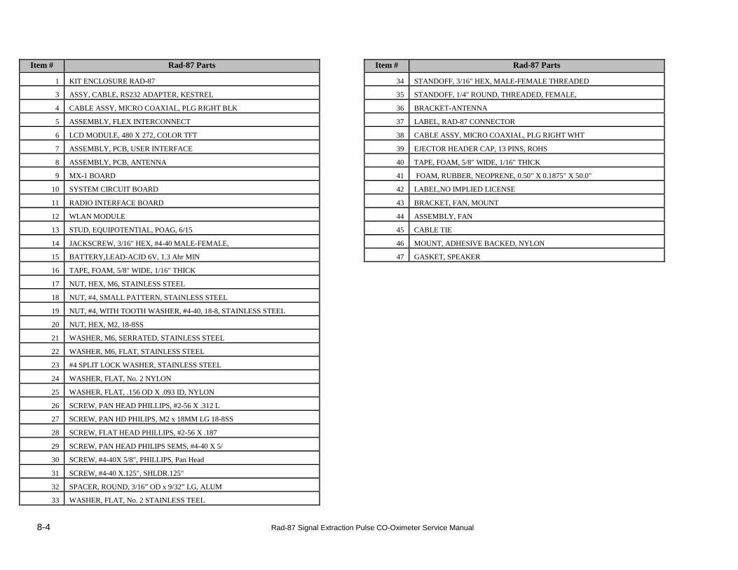
Item # Rad-87 Parts Item # Rad-87 Parts
1 KIT ENCLOSURE RAD-87 34 STANDOFF, 3/16" HEX, MALE-FEMALE THREADED
3 ASSY, CABLE, RS232 ADAPTER, KESTREL 35 STANDOFF, 1/4" ROUND, THREADED, FEMALE,
4 CABLE ASSY, MICRO COAXIAL, PLG RIGHT BLK 36 BRACKET-ANTENNA
5 ASSEMBLY, FLEX INTERCONNECT 37 LABEL, RAD-87 CONNECTOR
6 LCD MODULE, 480 X 272, COLOR TFT 38 CABLE ASSY, MICRO COAXIAL, PLG RIGHT WHT
7 ASSEMBLY, PCB, USER INTERFACE 39 EJECTOR HEADER CAP, 13 PINS, ROHS
8 ASSEMBLY, PCB, ANTENNA 40 TAPE, FOAM, 5/8" WIDE, 1/16" THICK
9 MX-1 BOARD 41 FOAM, RUBBER, NEOPRENE, 0.50" X 0.1875" X 50.0"
10 SYSTEM CIRCUIT BOARD 42 LABEL,NO IMPLIED LICENSE
11 RADIO INTERFACE BOARD 43 BRACKET, FAN, MOUNT
12 WLAN MODULE 44 ASSEMBLY, FAN
13 STUD, EQUIPOTENTIAL, POAG, 6/15 45 CABLE TIE
14 JACKSCREW, 3/16" HEX, #4-40 MALE-FEMALE, 46 MOUNT, ADHESIVE BACKED, NYLON
15 BATTERY,LEAD-ACID 6V, 1.3 Ahr MIN 47 GASKET, SPEAKER
16 TAPE, FOAM, 5/8" WIDE, 1/16" THICK
17 NUT, HEX, M6, STAINLESS STEEL
18 NUT, #4, SMALL PATTERN, STAINLESS STEEL
19 NUT, #4, WITH TOOTH WASHER, #4-40, 18-8, STAINLESS STEEL
20 NUT, HEX, M2, 18-8SS
21 WASHER, M6, SERRATED, STAINLESS STEEL
22 WASHER, M6, FLAT, STAINLESS STEEL
23 #4 SPLIT LOCK WASHER, STAINLESS STEEL
24 WASHER, FLAT, No. 2 NYLON
25 WASHER, FLAT, .156 OD X .093 ID, NYLON
26 SCREW, PAN HEAD PHILLIPS, #2-56 X .312 L
27 SCREW, PAN HD PHILIPS, M2 x 18MM LG 18-8SS
28 SCREW, FLAT HEAD PHILLIPS, #2-56 X .187
29 SCREW, PAN HEAD PHILIPS SEMS, #4-40 X 5/
30 SCREW, #4-40X 5/8", PHILLIPS, Pan Head
31 SCREW, #4-40 X.125", SHLDR.125"
32 SPACER, ROUND, 3/16” OD x 9/32” LG, ALUM
33 WASHER, FLAT, No. 2 STAINLESS TEEL

8-5 Rad-87 Signal Extraction Pulse CO-Oximeter Service Manual