Embed Size (px)
Citation preview
187
(Example)
Racks
Sp
urG
ears
Hel
ical
Gea
rsIn
tern
alG
ears
Rac
ksC
P R
acks
& P
inio
nsM
iter
Gea
rsB
evel
Gea
rsS
crew
Gea
rsW
orm
Gea
r P
air
Bev
elG
earb
oxes
Oth
erP
rod
ucts
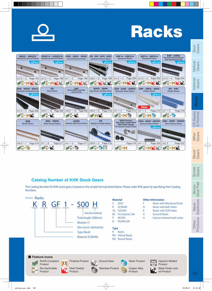
Induction hardened Total length (500mm)Module (1)Others (Ground + Machined Ends)Type (Rack)Material (SCM440)
Material Other InformationS S45C F Racks with Machined EndsK SCM440 D Racks with Bolt HolesSU SUS304 K Racks with Drill HolesBS Free Cutting brass C3604 G Ground RacksP MC901 H Induction hardened tooth surface D DURACON
TypeR RacksRH Helical RacksRO Round Racks
The Catalog Number for KHK stock gears is based on the simple formula listed below. Please order KHK gears by specifying their Catalog Numbers.
K R GF 1 - 500 H
Hardened Ground RacksMRGF・MRGFD
Series
m1.5 〜 3 Page 194
Hardened Ground RacksKRGF-H・KRGFD-H
Series
m1.5 〜 3 Page 196
Thermal Refi ned Ground Racks
Page 196
KRG・KRGF・KRGD
m1 〜 3 Page 198
SRG・SRGF・SRGFD・SRGFK
m0.5 〜 6
Series
Hardened Ground Racks Hardened RacksKRF-H・KRFD-H
Series
Page 200m1.5 〜 5
Hardened RacksSRF-H・SRFD-H
Series
Page 202m1.5 〜 6 Page 204
Thermal Refi ned Racks with Machined Ends
KRF・KRFD
m1.5 〜 5
SRAF・SRAFD・SRAFKSteel Racks with Machined Ends
Page 206m1.5 〜 4
Steel Racks
Page 208
SR
m0.5 〜 10
Steel Racks with Ma-chined Ends
Page 209
SRF
m0.5 〜 10
Steel Racks with Bolts Holes
Page 210
SRFD・SRFK
m0.5 〜 6
Series
Stainless Steel Racks
Page 212
SUR・SURF・SURFD
m1 〜 4
Plastic Racks
Page 214
DRF・DRFD・DRFK
m1 〜 4
Plastic Racks
Page 216
PR・PRF
m1 〜 3
Brass Racks
Page 216
BSR
m0.5 〜 1
SRO・SROSSteel Round Racks
m1 〜 6 Page 217
SUROStainless Steel Round Racks
m1 〜 3 Page 217
DRMolded Flexible Racks
m0.8 〜 2 Page 218 Page 218
For Molded Flexible Racks
SSDR PinionsARL Rack Guide Rails
SRS Rack Clamps
KRHG・KRHGF・KRHGFDGround Helical Racks
m1 〜 3 Page 220
SRH・SRHF・SRHFDSteel Helical Racks
m2, 3 Page 222
Catalog Number of KHK Stock Gears
Series
Series
Series
New
Series
■ Feature IconsRoHS Compliant Product
Finished Product Ground Gear Resin Product Injection Molded Product
Re-machinableProduct
Heat Treated Product
Stainless Product Copper Alloy Product
Black Oxide coat-ed Product
Racks
catalog_usa.indb 187 15/05/21 15:16:43
188
Racks
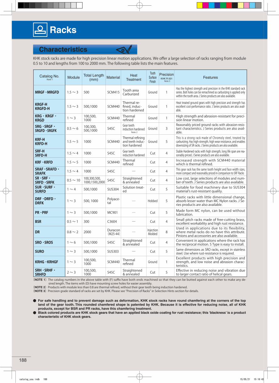
Characteristics
Catalog No.Note 1 Module Total Length
(mm) Material Heat Treatment
Tooth Surface Finish
Precision KHK R 001
Note 3Features
MRGF ・MRGFD 1.5 〜 3 500 SCM415 Tooth area Carburized Ground 1
Has the highest strength and precision in the KHK standard rack series. Bolt holes can be remachined as carburizing is applied only within the tooth area. J Series products are also available.
KRGF-HKRGFD-H 1.5 〜 3 500,1000 SCM440
Thermal re-fined, induc-tion hardened
Ground 1Heat treated ground gears with high precision and strength has excellent cost-performance ratio. J Series products are also avail-able.
KRG・KRGF・KRGD 1 〜 3 100,500,
1000 SCM440 Thermal refined Ground 1 High strength and abrasion-resistant for preci-
sion linear motion.
SRG・SRGF・SRGFD・SRGFK 0.5 〜 6 100,300,
500,1000 S45CGear teeth induction hardened
Note 2Ground 3
Reasonably priced ground racks with abrasion-resis-tant characteristics. J Series products are also avail-able.
KRF-HKRFD-H 1.5 〜 5 1000 SCM440
Thermal refining and teeth induc-tion hardened
Ground 5This is a strong rack made of Chromoly steel, treated by carburizing. Has high-strength, high wear resistance, and enables downsizing of SR racks. J Series products are also available.
SRF-HSRFD-H 1.5 〜 4 1000 S45C Gear teeth
induction hardened Cut 4 Stable Hardened racks with high strength, long life span are rea-sonably priced. J Series products are also available.
KRF・KRFD 1.5 〜 5 1000 SCM440 Thermal refined Cut 4 Increased strength with SCM440 material
which is thermal refined.SRAF ・SRAFD・SRAFK 1.5 〜 4 1000 S45C ― Cut 4 This gear rack has the same tooth height and face width sizes,
more compact and reasonably priced in comparison to SRF RacksSR・SRF・SRFD・SRFK 0.5 〜 10 100,300,500,
1000,1500,2000 S45C Straightened& annealed Cut 4 Low cost, large selections of modules and num-
ber of teeth. J Series products are also available.SUR・SURF・SURFD 1 〜 4 500,1000 SUS304 Solution treat-
ed Cut 5 Suitable for food machinery due to SUS304 material's rust-resistant quality.
DRF・DRFD・DRFK 1 〜 3 500, 1000 Polyace-
tal ― Hobbed 5Plastic racks with little dimensional change, absorb lesser water than MC Nylon racks. J Se-ries products are also available.
PR・PRF 1 〜 3 500,1000 MC901 ― Cut 5 Made form MC nylon, can be used without lubrication.
BSR 0.5 〜 1 300 C3604 ― Cut 4 Small pitch racks made of free-cutting brass, excellent workability and high rust resistance.
DR 0.8 〜 2 2000 Duracon(M25-44) ― Injection
Molded 8Used in applications due to its flexibility, where metal racks do no have this attribute. Pinions and accessories are also available.
SRO・SROS 1 〜 6 500,1000 S45C Straightened& annealed Cut 4 Convenient in applications where the rack has
the reciprocal motion. S Type is easy to install.
SURO 1 〜 3 500,1000 SUS303 ― Cut 5 Same dimensions as SRO racks, except in stainless steel. Use where rust-resistance is required.
KRHG・KRHGF 1 〜 3 100,500,1000 SCM440 Thermal
refined Ground 1Excellent products with high precision and strength, and low noise and abrasion charac-teristics.
SRH・SRHF・SRHFD 2 〜 3 100,500,
1000 S45C Straightened& annealed Cut 5 Effective in reducing noise and vibration due
to larger contact ratio of helical gears.〔NOTE 1〕The catalog numbers in the above table with (F) suffix have both ends machined so that they can be butted against each other to make any de-
sired length. The items with (D) have mounting screw holes for easier assembly.〔NOTE 2〕Products with module less than 0.8 are thermal refined, without their gear teeth being induction hardened.〔NOTE 3〕Precision grade standard of racks are set by KHK. Please see “Precision of Racks” in Selection Hints section for details.
For safe handling and to prevent damage such as deformation, KHK stock racks have round chamfering at the corners of the top land of the gear tooth. This rounded chamfered shape is patented by KHK. Because it is effective for reducing noise, all of KHK products, except for BSR and PR racks, have this chamfering treatment.Black colored products are KHK stock gears that have an applied black oxide coating for rust resistance; this ‘blackness’ is a product characteristic of KHK stock gears.
KHK stock racks are made for high precision linear motion applications. We offer a large selection of racks ranging from module 0.5 to 10 and lengths from 100 to 2000 mm. The following table lists the main features.
catalog_usa.indb 188 15/05/21 15:16:43
189
KHK Technical Information
Please select the most suitable products by carefully considering the characteristics of items and contents of the product ta-bles. It is also important to read all applicable notes before the final selection.
Selection Hints
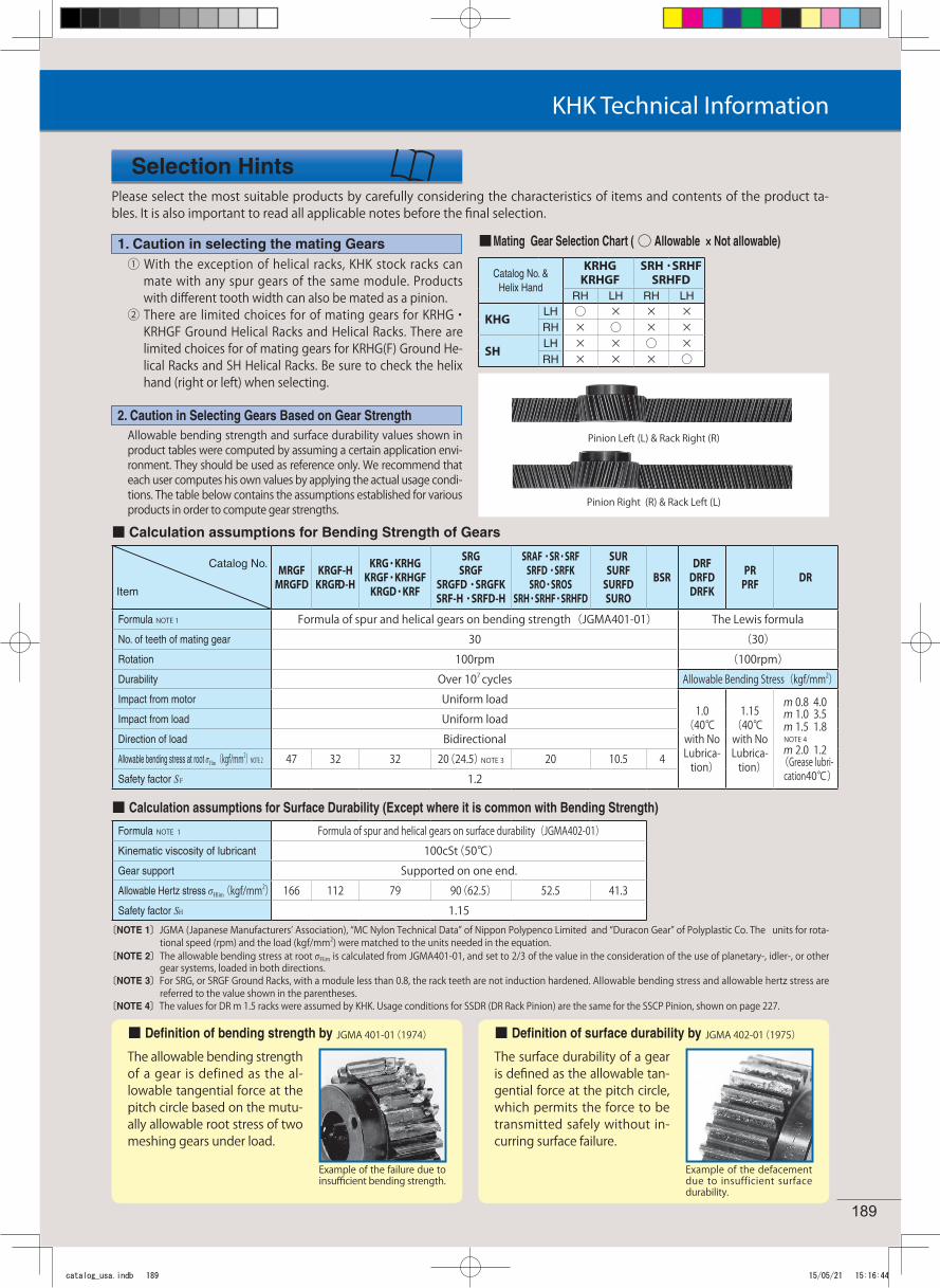
① With the exception of helical racks, KHK stock racks can mate with any spur gears of the same module. Products with different tooth width can also be mated as a pinion.
② There are limited choices for of mating gears for KRHG・KRHGF Ground Helical Racks and Helical Racks. There are limited choices for of mating gears for KRHG(F) Ground He-lical Racks and SH Helical Racks. Be sure to check the helix hand (right or left) when selecting.
1. Caution in selecting the mating Gears
Allowable bending strength and surface durability values shown in product tables were computed by assuming a certain application envi-ronment. They should be used as reference only. We recommend that each user computes his own values by applying the actual usage condi-tions. The table below contains the assumptions established for various products in order to compute gear strengths.
〔NOTE 1〕JGMA (Japanese Manufacturers’ Association), “MC Nylon Technical Data” of Nippon Polypenco Limited and “Duracon Gear” of Polyplastic Co. The units for rota-tional speed (rpm) and the load (kgf/mm2) were matched to the units needed in the equation.
〔NOTE 2〕The allowable bending stress at root σFlim is calculated from JGMA401-01, and set to 2/3 of the value in the consideration of the use of planetary-, idler-, or other gear systems, loaded in both directions.
〔NOTE 3〕For SRG, or SRGF Ground Racks, with a module less than 0.8, the rack teeth are not induction hardened. Allowable bending stress and allowable hertz stress are referred to the value shown in the parentheses.
〔NOTE 4〕The values for DR m 1.5 racks were assumed by KHK. Usage conditions for SSDR (DR Rack Pinion) are the same for the SSCP Pinion, shown on page 227.
2. Caution in Selecting Gears Based on Gear Strength
The allowable bending strength of a gear is defined as the al-lowable tangential force at the pitch circle based on the mutu-ally allowable root stress of two meshing gears under load.
Example of the failure due to insufficient bending strength.
The surface durability of a gear is defined as the allowable tan-gential force at the pitch circle, which permits the force to be transmitted safely without in-curring surface failure.
Example of the defacement due to insufficient surface durability.
Pinion Left (L) & Rack Right (R)
Pinion Right (R) & Rack Left (L)
■ Mating Gear Selection Chart ( ○ Allowable × Not allowable)
Catalog No.
Item
MRGFMRGFD
KRGF-HKRGFD-H
KRG・KRHGKRGF・KRHGF
KRGD・KRF
SRGSRGF
SRGFD・SRGFKSRF-H・SRFD-H
SRAF・SR・SRFSRFD・SRFKSRO・SROS
SRH・SRHF・SRHFD
SURSURF
SURFDSURO
BSRDRF
DRFDDRFK
PRPRF DR
Formula NOTE 1 Formula of spur and helical gears on bending strength(JGMA401-01) The Lewis formulaNo. of teeth of mating gear 30 (30)Rotation 100rpm (100rpm)Durability Over 107 cycles Allowable Bending Stress(kgf/mm2)Impact from motor Uniform load
1.0 (40℃ with No Lubrica-
tion)
1.15 (40℃ with No Lubrica-
tion)
m 0.8 4.0m 1.0 3.5m 1.5 1.8 NOTE 4m 2.0 1.2
(Grease lubri-cation40℃)
Impact from load Uniform loadDirection of load BidirectionalAllowable bending stress at root σ Flim(kgf/mm2) NOTE 2 47 32 32 20(24.5)NOTE 3 20 10.5 4Safety factor SF 1.2
Formula NOTE 1 Formula of spur and helical gears on surface durability(JGMA402-01)Kinematic viscosity of lubricant 100cSt(50℃)Gear support Supported on one end.Allowable Hertz stress σHlim(kgf/mm2) 166 112 79 90(62.5) 52.5 41.3Safety factor SH 1.15
■ Calculation assumptions for Bending Strength of Gears
■ Calculation assumptions for Surface Durability (Except where it is common with Bending Strength)
■ Definition of bending strength by JGMA 401-01(1974) ■ Definition of surface durability by JGMA 402-01(1975)
Catalog No. &Helix Hand
KRHGKRHGF
SRH・SRHFSRHFD
RH LH RH LH
KHGLH ○ × × ×RH × ○ × ×
SHLH × × ○ ×RH × × × ○
catalog_usa.indb 189 15/05/21 15:16:44
190
Racks
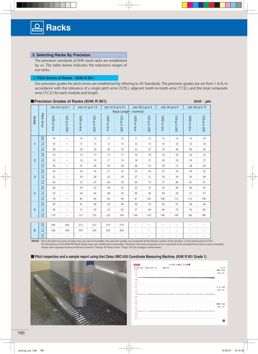
The precision standards of KHK stock racks are established by us. The table below indicates the tolerance ranges of our racks.
3. Selecting Racks By Precision
■ Precision Grades of Racks (KHK R 001) Unit:μm
Grade
Pitch E
rror
over m0.4 up to 1 over m1 up to 1.6 over m1.6 up to 2.5 over m2.5 up to 4 over m4 up to 6 over m6 up to 10Rack Length (nominal)1000 or less
1500 up to 2000
1000 or less
1500 up to 2000
1000 or less
1500 up to 2000
1000 or less
1500 up to 2000
1000 or less
1500 up to 2000
1000 or less
1500 up to 2000
1
S.P.E. 10 - 10 12 11 12 11 13 13 14 14 16
T.T.E. 10 - 11 13 12 14 13 15 14 16 16 18
T.C.E. 28 - 29 33 30 35 32 37 35 40 40 45
2
S.P.E. 14 - 14 17 15 17 16 18 18 20 20 23
T.T.E. 16 - 16 19 17 19 18 21 20 24 24 27
T.C.E. 39 - 41 48 43 49 46 53 50 57 58 64
3
S.P.E. 20 - 20 24 21 25 23 26 25 29 29 32
T.T.E. 22 - 24 28 25 29 27 31 30 34 34 40
T.C.E. 56 - 57 67 60 70 64 74 71 80 81 91
4
S.P.E. 28 - 29 33 30 35 32 37 35 40 40 45
T.T.E. 33 - 34 42 38 43 40 46 44 50 51 57
T.C.E. 79 - 81 95 85 99 91 105 100 115 115 130
5
S.P.E. 39 - 41 48 43 49 46 53 50 57 58 64
T.T.E. 49 - 51 59 53 62 57 69 66 75 76 85
T.C.E. 110 - 115 135 120 140 130 145 140 160 160 180
8
S.P.E. 206 206 212 212 219 219 - - - - - -
T.T.E. 330 330 339 339 350 350 - - - - - -
T.C.E. - - - - - - - - - - - -
〔NOTE〕Since the pitch accuracy of racks may vary due to humidity, the precision grades are evaluated at the bottom surface of the product, at the temperature of 20℃ . The dimensions of the KHK PR Plastic Racks may vary widely due to humidity. Therefore, the total composite error is assumed to be excluded from this accuracy standard. Please refer separate technical reference book to “Design of Plastic Gears” (Page 107) for change in dimensions.
■ Pitch inspection and a sample report using Karl Zeiss UMC-550 Coordinate Measuring Machine. (KHK R 001 Grade 1)
① Pitch Errors of Racks(KHK R 001)Our precision grades for pitch errors are established by referring to JIS Standards. The precision grades are set from 1 to 8, in accordance with the tolerance of a single pitch error (S.P.E.), adjacent tooth-to-tooth error (T.T.E.), and the total composite error (T.C.E.) for each module and length.
catalog_usa.indb 190 15/05/21 15:16:45
191
KHK Technical Information
Less than 0.03mm
Measuring point
1.0mmHeight
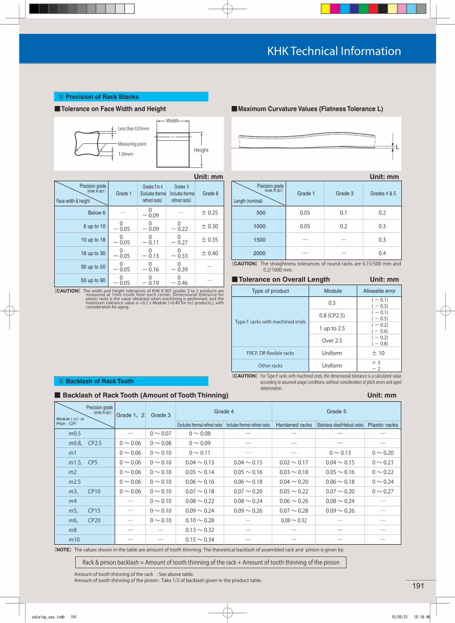
■ Tolerance on Face Width and Height
Precision grade(KHK R 001)
Face width & heightGrade 1
Grades 3 to 4 (Excludes thermal
refined racks)
Grades 5(Includes thermal
refined racks)Grade 8
Below 6 ― 0- 0.09 ― ± 0.25
6 up to 10 0- 0.05
0- 0.09
0- 0.22 ± 0.30
10 up to 18 0- 0.05
0- 0.11
0- 0.27 ± 0.35
18 up to 30 0- 0.05
0- 0.13
0- 0.33 ± 0.40
30 up to 50 0- 0.05
0- 0.16
0- 0.39 ―
50 up to 90 0- 0.05
0- 0.19
0- 0.46 ―
〔CAUTION〕The width and height tolerances of KHK R 001 grades 3 to 5 products are measured at 1mm inside from each corner. Dimensional tolerance for plastic racks is the value obtained when machining is performed, and the maximum tolerance value is +0.2 x Module (+0.40 for m2 products.), with consideration for aging.
Precision grade(KHK R 001)
Length (nominal)Grade 1 Grade 3 Grades 4 & 5
500 0.05 0.1 0.2
1000 0.05 0.2 0.3
1500 ― ― 0.3
2000 ― ― 0.4〔CAUTION〕The straightness tolerances of round racks are 0.15/500 mm and
0.2/1000 mm.
■ Tolerance on Overall Length Unit: mm
( )
〔CAUTION〕For Type-F racks with machined ends, the dimensional tolerance is a calculated value according to assumed usage conditions, without consideration of pitch errors and aged deterioration.
■ Backlash of Rack Tooth (Amount of Tooth Thinning)
Precision grade(KHK R 001)
Module ( m) orPitch(CP)
Grade 1、2 Grade 3Grade 4 Grade 5
Excludes thermal refined racks Includes thermal refined racks Hardened racks Stainless steel/Helical racks Plastic racks
m0.5 ― 0 〜 0.07 0 〜 0.08 ― ― ― ―m0.8, CP2.5 0 〜 0.06 0 〜 0.08 0 〜 0.09 ― ― ― ―m1 0 〜 0.06 0 〜 0.10 0 〜 0.11 ― ― 0 〜 0.13 0 〜 0.20m1.5, CP5 0 〜 0.06 0 〜 0.10 0.04 〜 0.13 0.04 〜 0.15 0.02 〜 0.17 0.04 〜 0.15 0 〜 0.21m2 0 〜 0.06 0 〜 0.10 0.05 〜 0.14 0.05 〜 0.16 0.03 〜 0.18 0.05 〜 0.16 0 〜 0.22m2.5 0 〜 0.06 0 〜 0.10 0.06 〜 0.16 0.06 〜 0.18 0.04 〜 0.20 0.06 〜 0.18 0 〜 0.24m3, CP10 0 〜 0.06 0 〜 0.10 0.07 〜 0.18 0.07 〜 0.20 0.05 〜 0.22 0.07 〜 0.20 0 〜 0.27m4 ― 0 〜 0.10 0.08 〜 0.22 0.08 〜 0.24 0.06 〜 0.26 0.08 〜 0.24 ―m5, CP15 ― 0 〜 0.10 0.09 〜 0.24 0.09 〜 0.26 0.07 〜 0.28 0.09 〜 0.26 ―m6, CP20 ― 0 〜 0.10 0.10 〜 0.28 ― 0.08 〜 0.32 ― ―m8 ― ― 0.13 〜 0.32 ― ― ― ―m10 ― ― 0.15 〜 0.34 ― ― ― ―
Unit: mm
〔NOTE〕The values shown in the table are amount of tooth thinning. The theoretical backlash of assembled rack and pinion is given by:
Amount of tooth thinning of the rack : See above table. Amount of tooth thinning of the pinion : Take 1/2 of backlash given in the product table.
Rack & pinion backlash = Amount of tooth thinning of the rack + Amount of tooth thinning of the pinion
② Precision of Rack Blanks
③ Backlash of Rack Tooth
Type of product Module Allowable error
Type F racks with machined ends
0.5 ( - 0.1)( - 0.3)
0.8 (CP2.5) ( - 0.1)( - 0.5)
1 up to 2.5 ( - 0.2)( - 0.6)
Over 2.5 ( - 0.2)( - 0.8)
FRCP, DR flexible racks Uniform ± 10
Other racks Uniform + 3- 2
Width
Unit: mmUnit: mm
■ Maximum Curvature Values (Flatness Tolerance L)
catalog_usa.indb 191 15/05/21 15:16:46
192
Racks
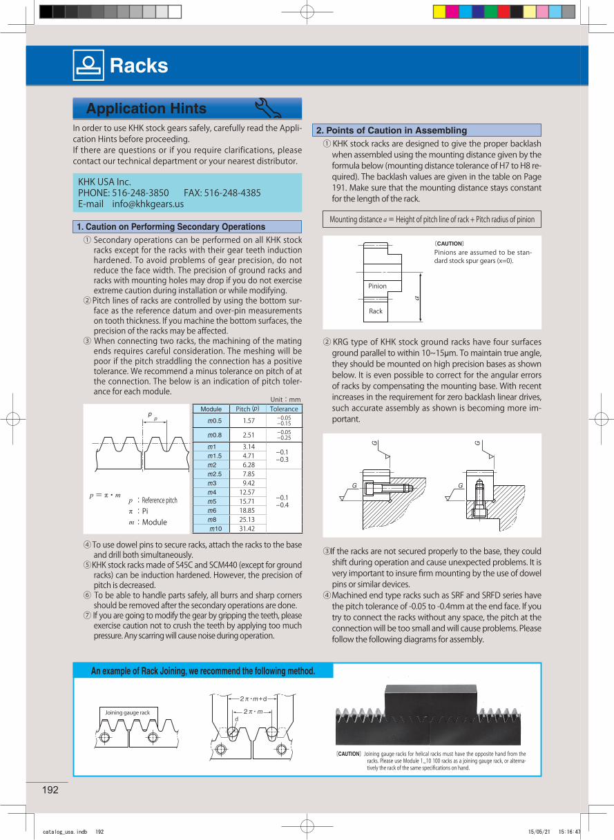
An example of Rack Joining, we recommend the following method.
〔CAUTION〕Joining gauge racks for helical racks must have the opposite hand from the racks. Please use Module 1~10 100 racks as a joining gauge rack, or alterna-tively the rack of the same specifications on hand.
KHK USA Inc.PHONE: 516-248-3850 FAX: 516-248-4385E-mail [email protected]
Application Hints
1. Caution on Performing Secondary Operations
2. Points of Caution in Assembling
Mounting distance a = Height of pitch line of rack + Pitch radius of pinion
〔CAUTION〕Pinions are assumed to be stan-dard stock spur gears (x=0).
d
Module Pitch (p) Tolerancem0.5 1.57 -0.05
-0.15
m0.8 2.51 -0.05-0.25
m1 3.14-0.1-0.3m1.5 4.71
m2 6.28m2.5 7.85
-0.1-0.4
m3 9.42m4 12.57m5 15.71m6 18.85m8 25.13m10 31.42
p = π・mp :Reference pitchπ:Pim :Module
p
Unit:mm
Pinion
Rack
Joining gauge rack
In order to use KHK stock gears safely, carefully read the Appli-cation Hints before proceeding. If there are questions or if you require clarifications, please contact our technical department or your nearest distributor.
① KHK stock racks are designed to give the proper backlash when assembled using the mounting distance given by the formula below (mounting distance tolerance of H7 to H8 re-quired). The backlash values are given in the table on Page 191. Make sure that the mounting distance stays constant for the length of the rack.
② KRG type of KHK stock ground racks have four surfaces ground parallel to within 10~15μm. To maintain true angle, they should be mounted on high precision bases as shown below. It is even possible to correct for the angular errors of racks by compensating the mounting base. With recent increases in the requirement for zero backlash linear drives, such accurate assembly as shown is becoming more im-portant.
③ If the racks are not secured properly to the base, they could shift during operation and cause unexpected problems. It is very important to insure firm mounting by the use of dowel pins or similar devices.
④ Machined end type racks such as SRF and SRFD series have the pitch tolerance of -0.05 to -0.4mm at the end face. If you try to connect the racks without any space, the pitch at the connection will be too small and will cause problems. Please follow the following diagrams for assembly.
① Secondary operations can be performed on all KHK stock racks except for the racks with their gear teeth induction hardened. To avoid problems of gear precision, do not reduce the face width. The precision of ground racks and racks with mounting holes may drop if you do not exercise extreme caution during installation or while modifying.
② Pitch lines of racks are controlled by using the bottom sur-face as the reference datum and over-pin measurements on tooth thickness. If you machine the bottom surfaces, the precision of the racks may be affected.
③ When connecting two racks, the machining of the mating ends requires careful consideration. The meshing will be poor if the pitch straddling the connection has a positive tolerance. We recommend a minus tolerance on pitch of at the connection. The below is an indication of pitch toler-ance for each module.
④ To use dowel pins to secure racks, attach the racks to the base and drill both simultaneously.
⑤ KHK stock racks made of S45C and SCM440 (except for ground racks) can be induction hardened. However, the precision of pitch is decreased.
⑥ To be able to handle parts safely, all burrs and sharp corners should be removed after the secondary operations are done.
⑦ If you are going to modify the gear by gripping the teeth, please exercise caution not to crush the teeth by applying too much pressure. Any scarring will cause noise during operation.
catalog_usa.indb 192 15/05/21 15:16:47
0.2~0.6 SRF2-1000SRF2-1000
SRF2-1000SRF2-1000
SRF2-1000SRF2-1000
SRF2-1000SRF2-1000
SRF2-1000SRF2-1000
193
KHK Technical Information
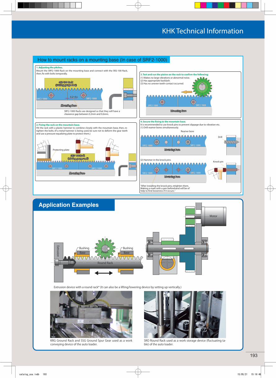
Extrusion device with a round rack* (It can also be a lifting/lowering device by setting up vertically.)
Application Examples
Motor
Pinion
Round Rack
BaseBaseBushing Bushing
Extrusion
KRG Ground Rack and SSG Ground Spur Gear used as a work conveying device of the auto loader.
SRO Round Rack used as a work storage device (fluctuating ta-ble) of the auto loader.
0.2~0.6 SRF2-1000SRF2-1000
SRF2-1000SRF2-1000
SRF2-1000SRF2-1000
SRF2-1000SRF2-1000
SRF2-1000SRF2-1000
How to mount racks on a mounting base (In case of SRF2-1000)
1. Adjusting the pitches.Mount the SRF2-1000 Rack on the mounting base and connect with the SR2-100 Rack, then, fix with bolts temporally.
0.2~0.6 SRF2-1000SRF2-1000
SRF2-1000SRF2-1000
SRF2-1000SRF2-1000
SRF2-1000SRF2-1000
SRF2-1000SRF2-1000
0.2~0.6 SRF2-1000SRF2-1000
SRF2-1000SRF2-1000
SRF2-1000SRF2-1000
SRF2-1000SRF2-1000
SRF2-1000SRF2-1000
2. Fixing the rack on the mountain base.Hit the rack with a plastic hammer to combine closely with the mountain base, then, re-tighten the bolts. (If a metal hammer is being used, be sure not to deform the gear teeth and use a pressure equalizing plate to protect them.)
3. Test and run the pinion on the rack to confirm the following;(1) Makes no large vibrations or abnormal noise.(2) Has appropriate backlash.(3) Has no uneven teeth-contact occurred.
4. Secure the fixing to the mountain base.It is recommended to use knock pins to prevent slippage due to vibration etc.(1) Drill reamer bores simultaneously.
(2) Hammer in the knock pins.
SRF2-1000 Racks are designed so that they will have a clearance gap between 0.2mm and 0.6mm.
Mounting Base
Mounting Base
Mounting Base
Mounting Base
Mounting Base
SR2-100 Rack (Joining gauge rack)
SR2-100 Rack (Joining gauge rack)
Protecting plate
Reamer bore
“After installing the knock pins, retighten them. Making a mark with a pen beforehand will be of help to find looseness if it occurs.”
Knock pin
Drill
catalog_usa.indb 193 15/05/21 15:16:48