Embed Size (px)
Citation preview
Page 1 of 24 V3.0-2016/8
Service Manual - English
RackCDU Service Manual
Edition August 2016
R11B-1528-02EN
R11A-0555-03EN
Page 2 of 24 V3.0-2016/8
Version history
Issue number Reason for update
1.0 / December 2015 Initial release
2.0 / February 2016 Minor modification
3.0 / August 2016 Minor modification
Page 3 of 24 V3.0-2016/8
Table of Contents Table of Contents ................................................................................................................................................ 3 1 Introduction .................................................................................................................................................. 4 2 Spare Parts List .............................................................................................................................................. 4 3 Standard/Unique Tools ................................................................................................................................. 4 4 Routine Maintenance ................................................................................................................................... 5
4.1 Refilling Server Coolant Reservoir ....................................................................................................... 5 5 Servicing the RackCDU Monitoring System .................................................................................................. 6
5.1 Update Firmware for RackCDU Monitoring System ............................................................................ 6 5.2 Determining the Network Address of a RackCDU Monitoring Box ..................................................... 9 5.3 Trouble Shooting the RackCDU Monitoring System .......................................................................... 10 5.4 Resetting the Monitoring box ........................................................................................................... 11 5.5 Replacing the Monitoring Box ........................................................................................................... 12 5.6 Replace the Power Supply ................................................................................................................. 13 5.7 Replacing the Facilities Pressure Sensor ........................................................................................... 14 5.8 Replacing the Server Coolant Pressure Sensor.................................................................................. 16 5.9 Replacing the Facilities Flow Sensor .................................................................................................. 18 5.10 Replacing the LED Indicator ............................................................................................................... 20 5.11 Replacing the Leak Sensor ................................................................................................................. 22 5.12 Replace Level Sensor ......................................................................................................................... 23
Page 4 of 24 V3.0-2016/8
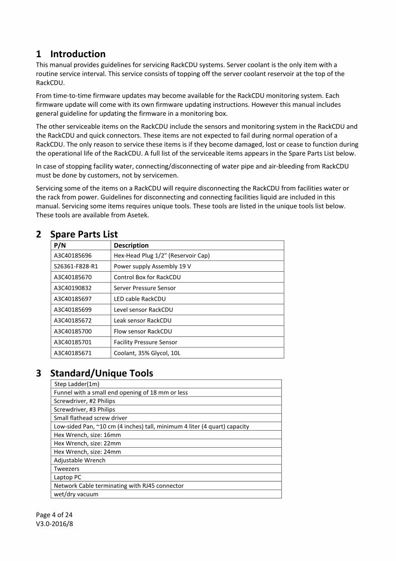
1 Introduction This manual provides guidelines for servicing RackCDU systems. Server coolant is the only item with a routine service interval. This service consists of topping off the server coolant reservoir at the top of the RackCDU.
From time-to-time firmware updates may become available for the RackCDU monitoring system. Each firmware update will come with its own firmware updating instructions. However this manual includes general guideline for updating the firmware in a monitoring box.
The other serviceable items on the RackCDU include the sensors and monitoring system in the RackCDU and the RackCDU and quick connectors. These items are not expected to fail during normal operation of a RackCDU. The only reason to service these items is if they become damaged, lost or cease to function during the operational life of the RackCDU. A full list of the serviceable items appears in the Spare Parts List below.
In case of stopping facility water, connecting/disconnecting of water pipe and air-bleeding from RackCDU must be done by customers, not by servicemen.
Servicing some of the items on a RackCDU will require disconnecting the RackCDU from facilities water or the rack from power. Guidelines for disconnecting and connecting facilities liquid are included in this manual. Servicing some items requires unique tools. These tools are listed in the unique tools list below. These tools are available from Asetek.
2 Spare Parts List P/N Description A3C40185696 Hex-Head Plug 1/2" (Reservoir Cap) S26361-F828-R1 Power supply Assembly 19 V A3C40185670 Control Box for RackCDU A3C40190832 Server Pressure Sensor A3C40185697 LED cable RackCDU A3C40185699 Level sensor RackCDU A3C40185672 Leak sensor RackCDU A3C40185700 Flow sensor RackCDU A3C40185701 Facility Pressure Sensor A3C40185671 Coolant, 35% Glycol, 10L
3 Standard/Unique Tools Step Ladder(1m) Funnel with a small end opening of 18 mm or less Screwdriver, #2 Philips Screwdriver, #3 Philips Small flathead screw driver Low-sided Pan, ~10 cm (4 inches) tall, minimum 4 liter (4 quart) capacity Hex Wrench, size: 16mm Hex Wrench, size: 22mm Hex Wrench, size: 24mm Adjustable Wrench Tweezers Laptop PC Network Cable terminating with RJ45 connector wet/dry vacuum
Page 5 of 24 V3.0-2016/8
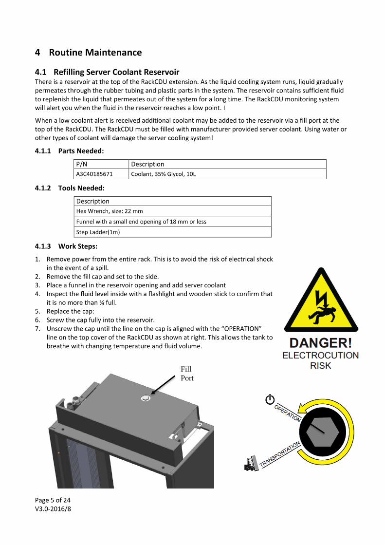
Fill Port
4 Routine Maintenance
4.1 Refilling Server Coolant Reservoir There is a reservoir at the top of the RackCDU extension. As the liquid cooling system runs, liquid gradually permeates through the rubber tubing and plastic parts in the system. The reservoir contains sufficient fluid to replenish the liquid that permeates out of the system for a long time. The RackCDU monitoring system will alert you when the fluid in the reservoir reaches a low point. I
When a low coolant alert is received additional coolant may be added to the reservoir via a fill port at the top of the RackCDU. The RackCDU must be filled with manufacturer provided server coolant. Using water or other types of coolant will damage the server cooling system!
4.1.1 Parts Needed:
P/N Description A3C40185671 Coolant, 35% Glycol, 10L
4.1.2 Tools Needed:
Description Hex Wrench, size: 22 mm
Funnel with a small end opening of 18 mm or less
Step Ladder(1m)
4.1.3 Work Steps:
1. Remove power from the entire rack. This is to avoid the risk of electrical shock in the event of a spill.
2. Remove the fill cap and set to the side. 3. Place a funnel in the reservoir opening and add server coolant 4. Inspect the fluid level inside with a flashlight and wooden stick to confirm that
it is no more than ¾ full. 5. Replace the cap: 6. Screw the cap fully into the reservoir. 7. Unscrew the cap until the line on the cap is aligned with the “OPERATION”
line on the top cover of the RackCDU as shown at right. This allows the tank to breathe with changing temperature and fluid volume.
Page 6 of 24 V3.0-2016/8
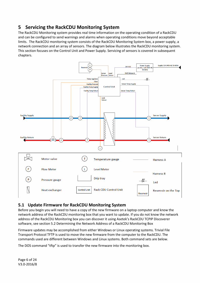
5 Servicing the RackCDU Monitoring System The RackCDU Monitoring system provides real time information on the operating condition of a RackCDU and can be configured to send warnings and alarms when operating conditions move beyond acceptable limits. The RackCDU monitoring system consists of the RackCDU Monitoring System box, a power supply, a network connection and an array of sensors. The diagram below illustrates the RackCDU monitoring system. This section focuses on the Control Unit and Power Supply. Servicing of sensors is covered in subsequent chapters.
5.1 Update Firmware for RackCDU Monitoring System Before you begin you will need to have a copy of the new firmware on a laptop computer and know the network address of the RackCDU monitoring box that you want to update. If you do not know the network address of the RackCDU Monitoring box you can discover it using Asetek’s RackCDU TCPIP Discoverer software, see section 5.2 Determining the Network Address of a RackCDU Monitoring Box
Firmware updates may be accomplished from either Windows or Linux operating systems. Trivial File Transport Protocol TFTP is used to move the new firmware from the computer to the RackCDU. The commands used are different between Windows and Linux systems. Both command sets are below.
The DOS command “tftp” is used to transfer the new firmware into the monitoring box.
Page 7 of 24 V3.0-2016/8
Network
Power
5.1.1 Parts Needed:
P/N Description n/a WebAgent.hex file (this file contains the new firmware)
5.1.2 Tools Needed:
Description Laptop PC
Network Cable terminating with RJ45 connector
Step Ladder(1m)
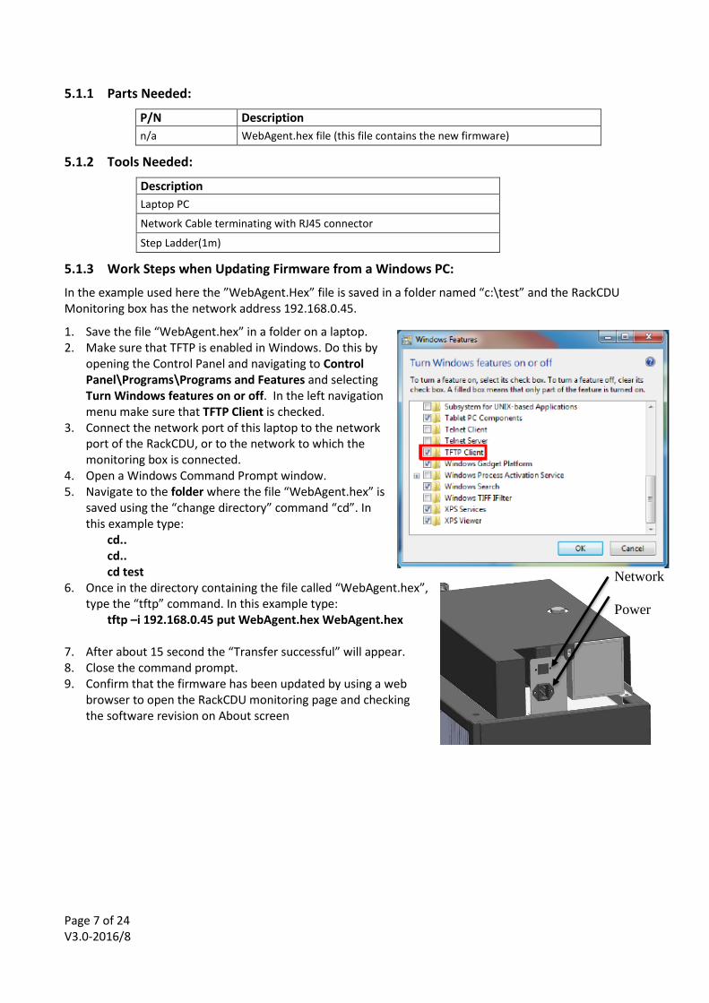
5.1.3 Work Steps when Updating Firmware from a Windows PC:
In the example used here the ”WebAgent.Hex” file is saved in a folder named “c:\test” and the RackCDU Monitoring box has the network address 192.168.0.45.
1. Save the file “WebAgent.hex” in a folder on a laptop. 2. Make sure that TFTP is enabled in Windows. Do this by
opening the Control Panel and navigating to Control Panel\Programs\Programs and Features and selecting Turn Windows features on or off. In the left navigation menu make sure that TFTP Client is checked.
3. Connect the network port of this laptop to the network port of the RackCDU, or to the network to which the monitoring box is connected.
4. Open a Windows Command Prompt window. 5. Navigate to the folder where the file “WebAgent.hex” is
saved using the “change directory” command “cd”. In this example type:
cd.. cd.. cd test
6. Once in the directory containing the file called “WebAgent.hex”, type the “tftp” command. In this example type:
tftp –i 192.168.0.45 put WebAgent.hex WebAgent.hex 7. After about 15 second the “Transfer successful” will appear. 8. Close the command prompt. 9. Confirm that the firmware has been updated by using a web
browser to open the RackCDU monitoring page and checking the software revision on About screen
Page 8 of 24 V3.0-2016/8
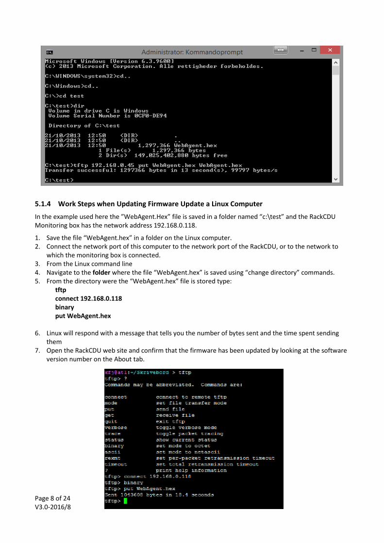
5.1.4 Work Steps when Updating Firmware Update a Linux Computer
In the example used here the ”WebAgent.Hex” file is saved in a folder named “c:\test” and the RackCDU Monitoring box has the network address 192.168.0.118.
1. Save the file “WebAgent.hex” in a folder on the Linux computer. 2. Connect the network port of this computer to the network port of the RackCDU, or to the network to
which the monitoring box is connected. 3. From the Linux command line 4. Navigate to the folder where the file “WebAgent.hex” is saved using “change directory” commands. 5. From the directory were the “WebAgent.hex” file is stored type:
tftp connect 192.168.0.118 binary put WebAgent.hex
6. Linux will respond with a message that tells you the number of bytes sent and the time spent sending
them 7. Open the RackCDU web site and confirm that the firmware has been updated by looking at the software
version number on the About tab.
Page 9 of 24 V3.0-2016/8
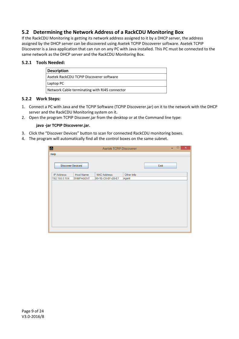
5.2 Determining the Network Address of a RackCDU Monitoring Box If the RackCDU Monitoring is getting its network address assigned to it by a DHCP server, the address assigned by the DHCP server can be discovered using Asetek TCPIP Discoverer software. Asetek TCPIP Discoverer is a Java application that can run on any PC with Java installed. This PC must be connected to the same network as the DHCP server and the RackCDU Monitoring Box.
5.2.1 Tools Needed:
Description Asetek RackCDU TCPIP Discoverer software
Laptop PC
Network Cable terminating with RJ45 connector
5.2.2 Work Steps:
1. Connect a PC with Java and the TCPIP Software (TCPIP Discoverer.jar) on it to the network with the DHCP server and the RackCDU Monitoring system on it.
2. Open the program TCPIP Discover.jar from the desktop or at the Command line type:
java -jar TCPIP Discoverer.jar.
3. Click the “Discover Devices” button to scan for connected RackCDU monitoring boxes. 4. The program will automatically find all the control boxes on the same subnet.
Page 10 of 24 V3.0-2016/8
5.3 Trouble Shooting the RackCDU Monitoring System This section covers replacing the monitoring box and/or it’s power supply. Both the monitoring box and its power supply are located at the top of the RackCDU under the top cover.
5.3.1 Tools Needed:
Description #2 Philips Screwdriver Step Ladder(1m) Laptop PC Network Cable terminating with RJ45 connector Multi-meter
5.3.2 Trouble Shooting a RackCDU Monitoring Box
When the RackCDU monitoring system is functioning properly the white LED near the top of the RackCDU should be illuminated and the web interface should be viewable by pointing a web browser at the network address of the monitoring box.
If the white LED is off and the web page from the monitoring box does not display: begin by checking the power system for the RackCDU.
1. Check that the power cord for the monitoring box is fully plugged into a power strip and that the strip is on.
2. Check that the power cord is fully plugged into the socket on the top right side of the RackCDU below the network port.
3. Remove the 4 screws holding the top cover of the RackCDU in place. Two are located bottom far side edge of the cover and two more are located at either end of the reservoir.
4. Lift off the cover and set it aside 5. Check that the cord from the rear of the power cable socket is fully plugged into the power supply 6. Check that the cable from the power supply and the cable to the monitoring box are fully connected.
If all of these elements are in good working order, begin by testing the power supply.
7. Disconnect the cable between the power supply and the monitoring box. Check that the power supply is delivering 19VDC. If it is not delivering the required voltage, replace the power supply.
If the power supply is working, check the power to the LED indicator:
8. Disconnect the LED cable from the monitoring box and test that the monitoring box is delivering 3VDC to the LED. If it is not change the monitoring box. If 3VDC is being delivered, replace the LED assembly.
If the LED Light is on but the web page from the monitoring box does not display, begin by checking the network address of the monitoring system using TCPIP Discoverer. If you are unable to determine the network address by using the TCPIP Discoverer program it may be necessary to reset the monitoring box.
Page 11 of 24 V3.0-2016/8
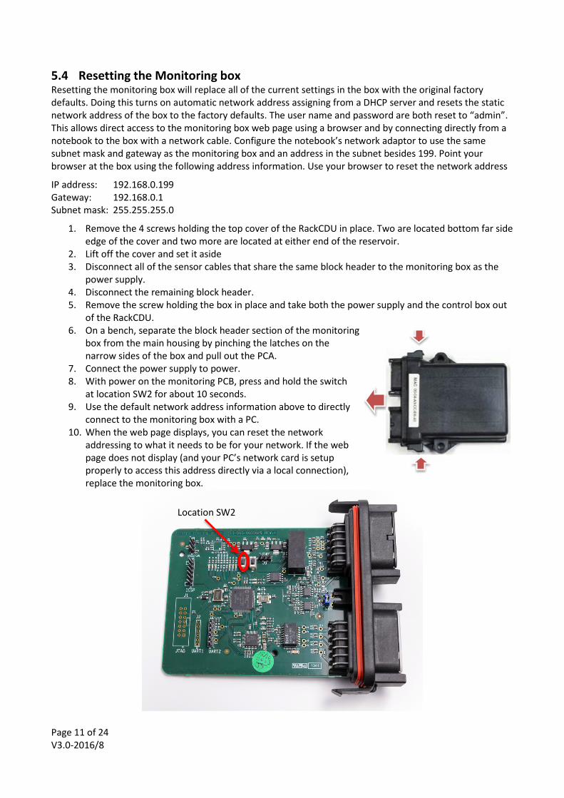
5.4 Resetting the Monitoring box Resetting the monitoring box will replace all of the current settings in the box with the original factory defaults. Doing this turns on automatic network address assigning from a DHCP server and resets the static network address of the box to the factory defaults. The user name and password are both reset to “admin”. This allows direct access to the monitoring box web page using a browser and by connecting directly from a notebook to the box with a network cable. Configure the notebook’s network adaptor to use the same subnet mask and gateway as the monitoring box and an address in the subnet besides 199. Point your browser at the box using the following address information. Use your browser to reset the network address
IP address: 192.168.0.199 Gateway: 192.168.0.1 Subnet mask: 255.255.255.0
1. Remove the 4 screws holding the top cover of the RackCDU in place. Two are located bottom far side edge of the cover and two more are located at either end of the reservoir.
2. Lift off the cover and set it aside 3. Disconnect all of the sensor cables that share the same block header to the monitoring box as the
power supply. 4. Disconnect the remaining block header. 5. Remove the screw holding the box in place and take both the power supply and the control box out
of the RackCDU. 6. On a bench, separate the block header section of the monitoring
box from the main housing by pinching the latches on the narrow sides of the box and pull out the PCA.
7. Connect the power supply to power. 8. With power on the monitoring PCB, press and hold the switch
at location SW2 for about 10 seconds. 9. Use the default network address information above to directly
connect to the monitoring box with a PC. 10. When the web page displays, you can reset the network
addressing to what it needs to be for your network. If the web page does not display (and your PC’s network card is setup properly to access this address directly via a local connection), replace the monitoring box.
Location SW2
Page 12 of 24 V3.0-2016/8
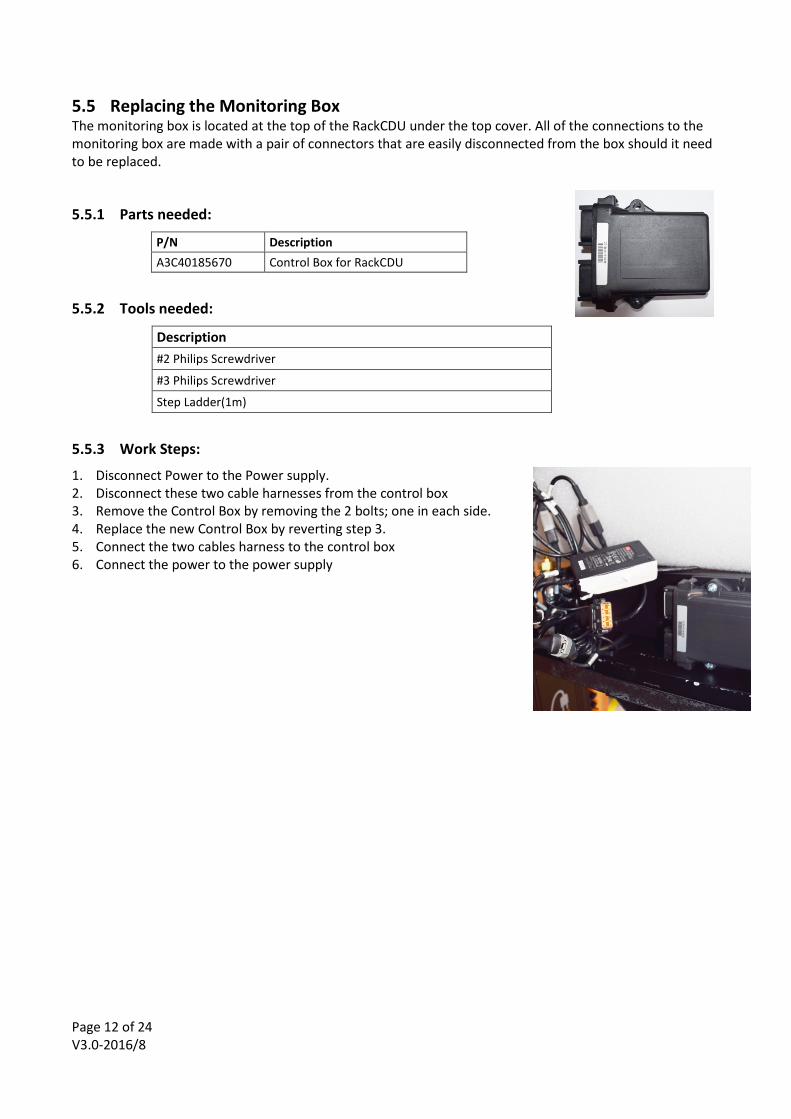
5.5 Replacing the Monitoring Box The monitoring box is located at the top of the RackCDU under the top cover. All of the connections to the monitoring box are made with a pair of connectors that are easily disconnected from the box should it need to be replaced.
5.5.1 Parts needed:
P/N Description A3C40185670 Control Box for RackCDU
5.5.2 Tools needed:
Description #2 Philips Screwdriver
#3 Philips Screwdriver
Step Ladder(1m)
5.5.3 Work Steps:
1. Disconnect Power to the Power supply. 2. Disconnect these two cable harnesses from the control box 3. Remove the Control Box by removing the 2 bolts; one in each side. 4. Replace the new Control Box by reverting step 3. 5. Connect the two cables harness to the control box 6. Connect the power to the power supply
Page 13 of 24 V3.0-2016/8
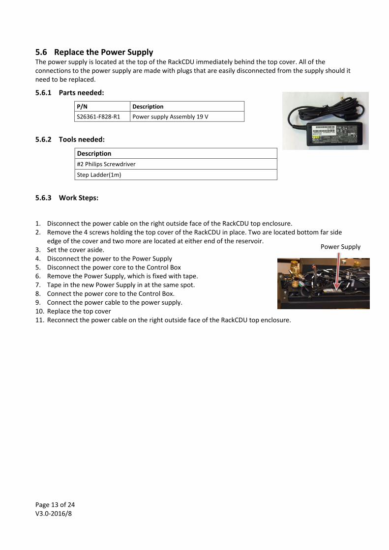
5.6 Replace the Power Supply The power supply is located at the top of the RackCDU immediately behind the top cover. All of the connections to the power supply are made with plugs that are easily disconnected from the supply should it need to be replaced.
5.6.1 Parts needed:
P/N Description S26361-F828-R1 Power supply Assembly 19 V
5.6.2 Tools needed:
Description #2 Philips Screwdriver
Step Ladder(1m)
5.6.3 Work Steps:
1. Disconnect the power cable on the right outside face of the RackCDU top enclosure. 2. Remove the 4 screws holding the top cover of the RackCDU in place. Two are located bottom far side
edge of the cover and two more are located at either end of the reservoir. 3. Set the cover aside. 4. Disconnect the power to the Power Supply 5. Disconnect the power core to the Control Box 6. Remove the Power Supply, which is fixed with tape. 7. Tape in the new Power Supply in at the same spot. 8. Connect the power core to the Control Box. 9. Connect the power cable to the power supply. 10. Replace the top cover 11. Reconnect the power cable on the right outside face of the RackCDU top enclosure.
Power Supply
Page 14 of 24 V3.0-2016/8
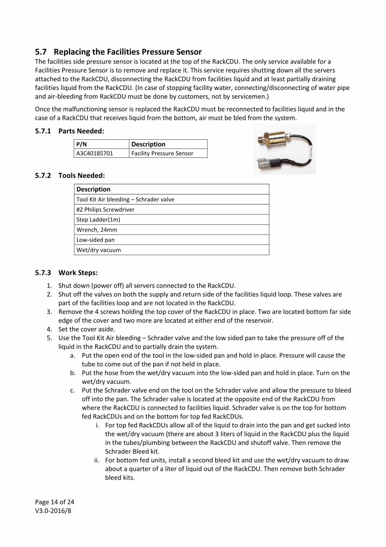
5.7 Replacing the Facilities Pressure Sensor The facilities side pressure sensor is located at the top of the RackCDU. The only service available for a Facilities Pressure Sensor is to remove and replace it. This service requires shutting down all the servers attached to the RackCDU, disconnecting the RackCDU from facilities liquid and at least partially draining facilities liquid from the RackCDU. (In case of stopping facility water, connecting/disconnecting of water pipe and air-bleeding from RackCDU must be done by customers, not by servicemen.)
Once the malfunctioning sensor is replaced the RackCDU must be reconnected to facilities liquid and in the case of a RackCDU that receives liquid from the bottom, air must be bled from the system.
5.7.1 Parts Needed:
P/N Description A3C40185701 Facility Pressure Sensor
5.7.2 Tools Needed:
Description Tool Kit Air bleeding – Schrader valve #2 Philips Screwdriver Step Ladder(1m) Wrench, 24mm Low-sided pan Wet/dry vacuum
5.7.3 Work Steps:
1. Shut down (power off) all servers connected to the RackCDU. 2. Shut off the valves on both the supply and return side of the facilities liquid loop. These valves are
part of the facilities loop and are not located in the RackCDU. 3. Remove the 4 screws holding the top cover of the RackCDU in place. Two are located bottom far side
edge of the cover and two more are located at either end of the reservoir. 4. Set the cover aside. 5. Use the Tool Kit Air bleeding – Schrader valve and the low sided pan to take the pressure off of the
liquid in the RackCDU and to partially drain the system. a. Put the open end of the tool in the low-sided pan and hold in place. Pressure will cause the
tube to come out of the pan if not held in place. b. Put the hose from the wet/dry vacuum into the low-sided pan and hold in place. Turn on the
wet/dry vacuum. c. Put the Schrader valve end on the tool on the Schrader valve and allow the pressure to bleed
off into the pan. The Schrader valve is located at the opposite end of the RackCDU from where the RackCDU is connected to facilities liquid. Schrader valve is on the top for bottom fed RackCDUs and on the bottom for top fed RackCDUs.
i. For top fed RackCDUs allow all of the liquid to drain into the pan and get sucked into the wet/dry vacuum (there are about 3 liters of liquid in the RackCDU plus the liquid in the tubes/plumbing between the RackCDU and shutoff valve. Then remove the Schrader Bleed kit.
ii. For bottom fed units, install a second bleed kit and use the wet/dry vacuum to draw about a quarter of a liter of liquid out of the RackCDU. Then remove both Schrader bleed kits.
Page 15 of 24 V3.0-2016/8
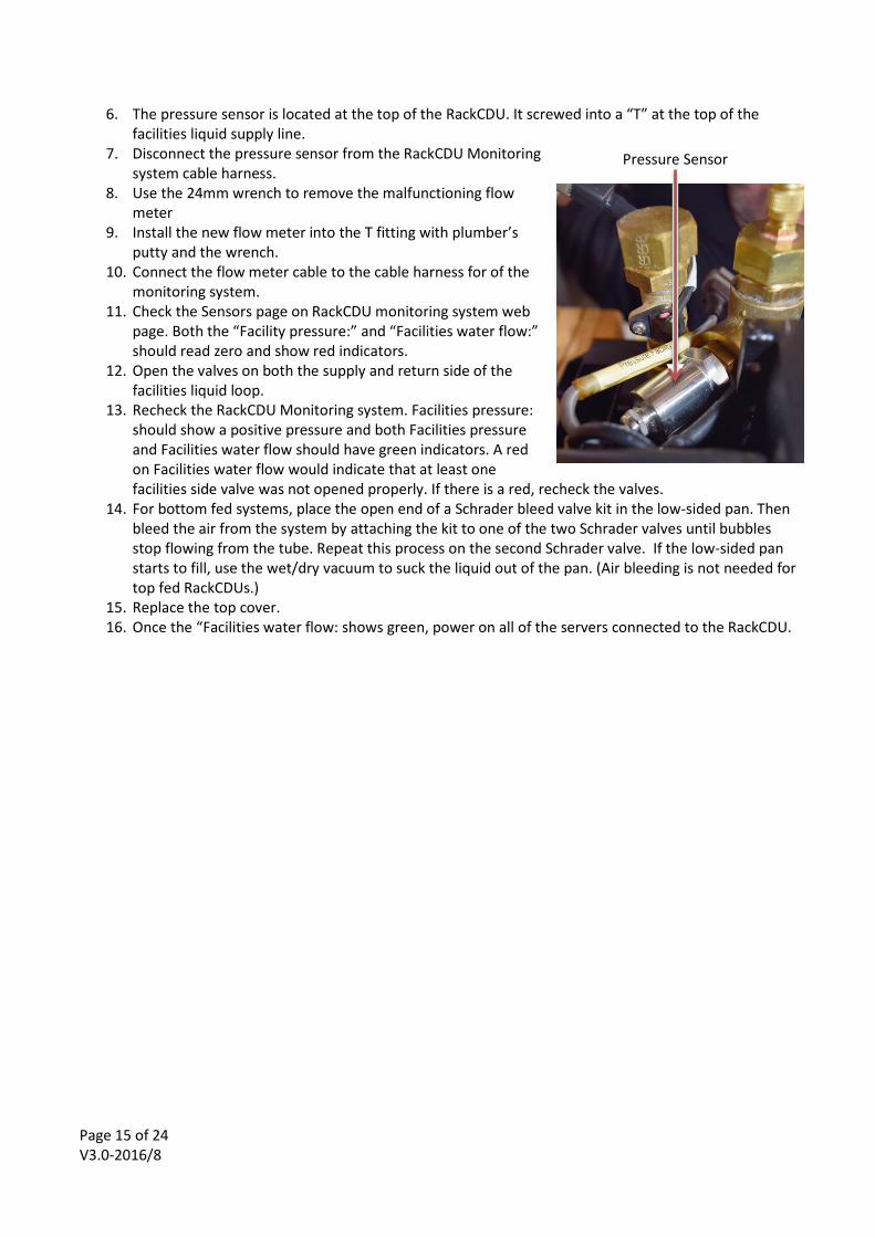
6. The pressure sensor is located at the top of the RackCDU. It screwed into a “T” at the top of the facilities liquid supply line.
7. Disconnect the pressure sensor from the RackCDU Monitoring system cable harness.
8. Use the 24mm wrench to remove the malfunctioning flow meter
9. Install the new flow meter into the T fitting with plumber’s putty and the wrench.
10. Connect the flow meter cable to the cable harness for of the monitoring system.
11. Check the Sensors page on RackCDU monitoring system web page. Both the “Facility pressure:” and “Facilities water flow:” should read zero and show red indicators.
12. Open the valves on both the supply and return side of the facilities liquid loop.
13. Recheck the RackCDU Monitoring system. Facilities pressure: should show a positive pressure and both Facilities pressure and Facilities water flow should have green indicators. A red on Facilities water flow would indicate that at least one facilities side valve was not opened properly. If there is a red, recheck the valves.
14. For bottom fed systems, place the open end of a Schrader bleed valve kit in the low-sided pan. Then bleed the air from the system by attaching the kit to one of the two Schrader valves until bubbles stop flowing from the tube. Repeat this process on the second Schrader valve. If the low-sided pan starts to fill, use the wet/dry vacuum to suck the liquid out of the pan. (Air bleeding is not needed for top fed RackCDUs.)
15. Replace the top cover. 16. Once the “Facilities water flow: shows green, power on all of the servers connected to the RackCDU.
Pressure Sensor
Page 16 of 24 V3.0-2016/8
5.8 Replacing the Server Coolant Pressure Sensor The server coolant pressure sensor is connected to the server coolant reservoir located at the top of the RackCDU extension. The only service available for the server coolant pressure sensor is to remove and replace it. This service requires shutting down all the servers attached to the RackCDU.
5.8.1 Parts Needed:
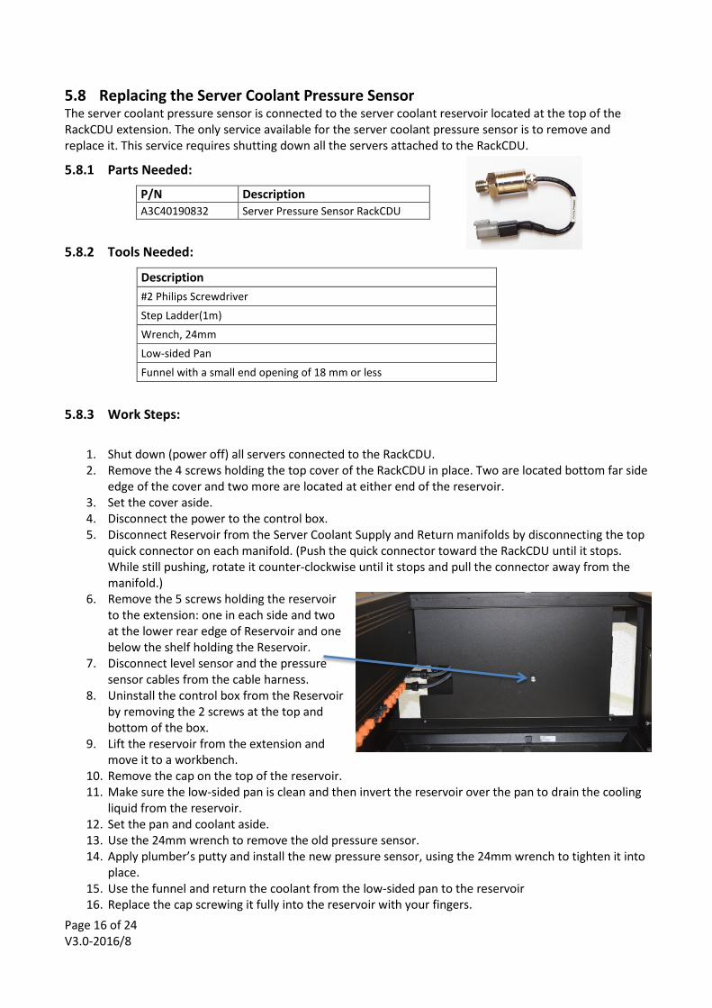
P/N Description A3C40190832 Server Pressure Sensor RackCDU
5.8.2 Tools Needed:
Description #2 Philips Screwdriver
Step Ladder(1m)
Wrench, 24mm
Low-sided Pan
Funnel with a small end opening of 18 mm or less
5.8.3 Work Steps:
1. Shut down (power off) all servers connected to the RackCDU. 2. Remove the 4 screws holding the top cover of the RackCDU in place. Two are located bottom far side
edge of the cover and two more are located at either end of the reservoir. 3. Set the cover aside. 4. Disconnect the power to the control box. 5. Disconnect Reservoir from the Server Coolant Supply and Return manifolds by disconnecting the top
quick connector on each manifold. (Push the quick connector toward the RackCDU until it stops. While still pushing, rotate it counter-clockwise until it stops and pull the connector away from the manifold.)
6. Remove the 5 screws holding the reservoir to the extension: one in each side and two at the lower rear edge of Reservoir and one below the shelf holding the Reservoir.
7. Disconnect level sensor and the pressure sensor cables from the cable harness.
8. Uninstall the control box from the Reservoir by removing the 2 screws at the top and bottom of the box.
9. Lift the reservoir from the extension and move it to a workbench.
10. Remove the cap on the top of the reservoir. 11. Make sure the low-sided pan is clean and then invert the reservoir over the pan to drain the cooling
liquid from the reservoir. 12. Set the pan and coolant aside. 13. Use the 24mm wrench to remove the old pressure sensor. 14. Apply plumber’s putty and install the new pressure sensor, using the 24mm wrench to tighten it into
place. 15. Use the funnel and return the coolant from the low-sided pan to the reservoir 16. Replace the cap screwing it fully into the reservoir with your fingers.
Page 17 of 24 V3.0-2016/8
17. Reattach the reservoir to the RackCDU extension – five screws. 18. Connect the pressure sensor and level sensor cables to the harness. 19. Reinstall control box on Reservoir. 20. Reconnect power to the control box. 21. Replace the top cover. 22. Reconnect the Reservoir to the RackCDU by connecting the
Red Female Connector from the Reservoir to the top Red Male Connector on the RackCDU and the Blue Female Connector from the Reservoir to the top Blue Male Connector on the RackCDU.
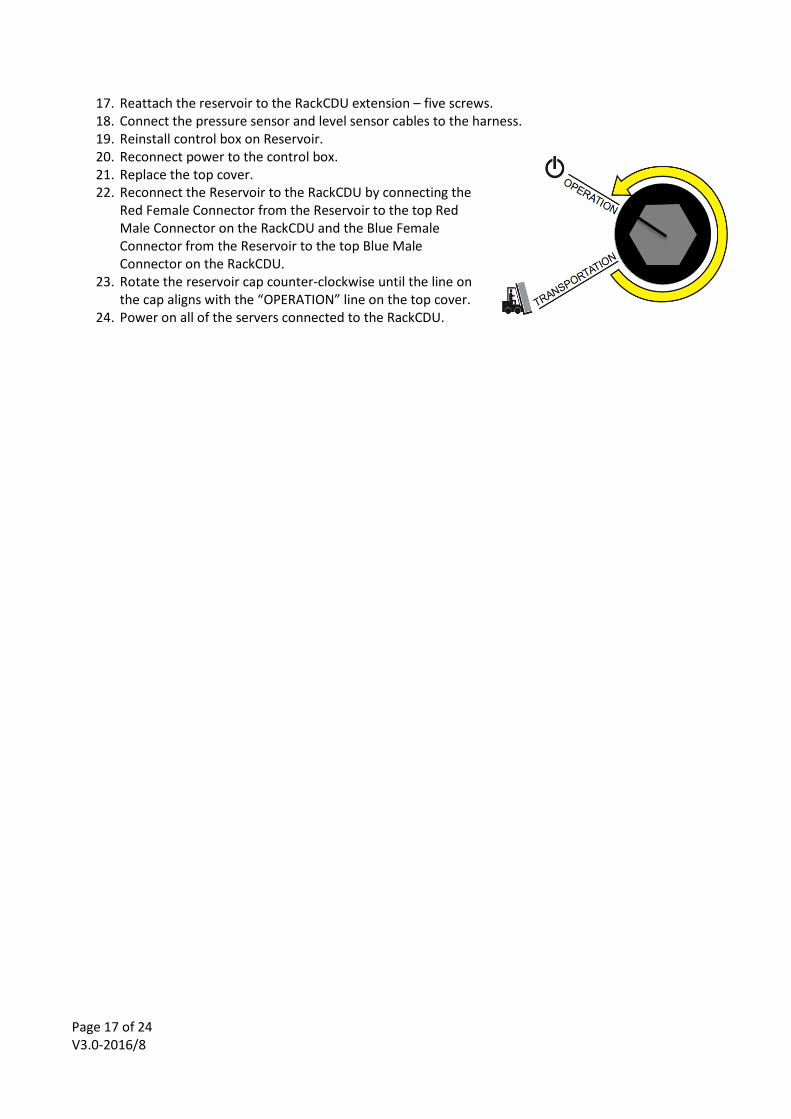
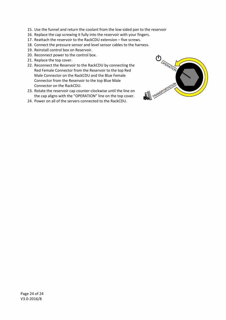
23. Rotate the reservoir cap counter-clockwise until the line on the cap aligns with the “OPERATION” line on the top cover.
24. Power on all of the servers connected to the RackCDU.
Page 18 of 24 V3.0-2016/8
5.9 Replacing the Facilities Flow Sensor The flow sensor is located at the top or the bottom of a RackCDU at the point where the RackCDU is connected to facilities liquid. The only service available for this sensor is to remove and replace it. This service requires shutting down all the servers attached to the RackCDU, disconnecting the RackCDU from facilities liquid and at least partially draining facilities liquid from the RackCDU. (In case of stopping facility water, connecting/disconnecting of water pipe must be done by customers, not by servicemen.)
Once the malfunctioning sensor is replaced the RackCDU must be reconnected to facilities liquid and in the case of a RackCDU that receives liquid from the bottom, air must be bled from the system.
5.9.1 Parts needed:
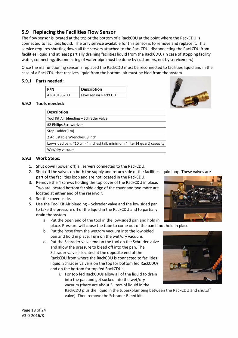
P/N Description A3C40185700 Flow sensor RackCDU
5.9.2 Tools needed:
Description Tool Kit Air bleeding – Schrader valve #2 Philips Screwdriver Step Ladder(1m) 2 Adjustable Wrenches, 8 inch Low-sided pan, ~10 cm (4 inches) tall, minimum 4 liter (4 quart) capacity Wet/dry vacuum
5.9.3 Work Steps:
1. Shut down (power off) all servers connected to the RackCDU. 2. Shut off the valves on both the supply and return side of the facilities liquid loop. These valves are
part of the facilities loop and are not located in the RackCDU. 3. Remove the 4 screws holding the top cover of the RackCDU in place.
Two are located bottom far side edge of the cover and two more are located at either end of the reservoir.
4. Set the cover aside. 5. Use the Tool Kit Air bleeding – Schrader valve and the low sided pan
to take the pressure off of the liquid in the RackCDU and to partially drain the system.
a. Put the open end of the tool in the low-sided pan and hold in place. Pressure will cause the tube to come out of the pan if not held in place.
b. Put the hose from the wet/dry vacuum into the low-sided pan and hold in place. Turn on the wet/dry vacuum.
c. Put the Schrader valve end on the tool on the Schrader valve and allow the pressure to bleed off into the pan. The Schrader valve is located at the opposite end of the RackCDU from where the RackCDU is connected to facilities liquid. Schrader valve is on the top for bottom fed RackCDUs and on the bottom for top fed RackCDUs.
i. For top fed RackCDUs allow all of the liquid to drain into the pan and get sucked into the wet/dry vacuum (there are about 3 liters of liquid in the RackCDU plus the liquid in the tubes/plumbing between the RackCDU and shutoff valve). Then remove the Schrader Bleed kit.
Page 19 of 24 V3.0-2016/8
ii. For bottom fed units, move the low-sided pan to a location under where the facilities liquid lines connect to the RackCDU, re-secure the wet/dry vacuum hose in the low-sided pan and turn it on.
6. Disconnect the facilities liquid line that connects to the RackCDU line with the flow sensor. On bottom fed units allow the RackCDU and the hose to drain into the low-sided pan and get sucked up by the wet/dry vacuum.
7. Use the wrenches to remove the hose connection hardware (CamLock or Tri-Clamp fittings) from the facilities return connection on the RackCDU.
8. Disconnect the flow sensor cable from the RackCDU sensor harness. For bottom fed units this connection should be near the bottom of the RackCDU and for top fed units it will be near the RackCDU monitoring box
9. Use a wrench to remove the malfunctioning flow sensor 10. Use a wrench to install the new flow sensor, with using Compound-flux(included new sensor) for
water-leak at the connection. 11. Connect the flow sensor cable to the RackCDU Monitor wire harness. 12. Use the wrenches to reinstall the hose connection hardware (CamLock or Tri-Clamp fittings on the
facilities return connection of the RackCDU. 13. Open the valves on both the supply and return side of the facilities liquid loop. 14. Recheck the RackCDU Monitoring system. Facilities water flow should have green indicators. A red
on Facilities water flow would indicate that at least one facilities side valve was not properly. If there is a red, recheck the valves.
15. For bottom fed systems, place the open end of a Schrader bleed valve kit in the low-sided pan. Then bleed the air from the system by attaching the kit to one of the two Schrader valves until bubbles stop flowing from the tube. Repeat this process on the second Schrader valve. If the low-sided pan starts to fill, use the wet/dry vacuum to suck the liquid out of the pan. (Air bleeding is not needed for top fed RackCDUs.)
16. Replace the top cover. 17. Once the “Facilities water flow: shows green, power on all of the servers connected to the RackCDU.
Page 20 of 24 V3.0-2016/8
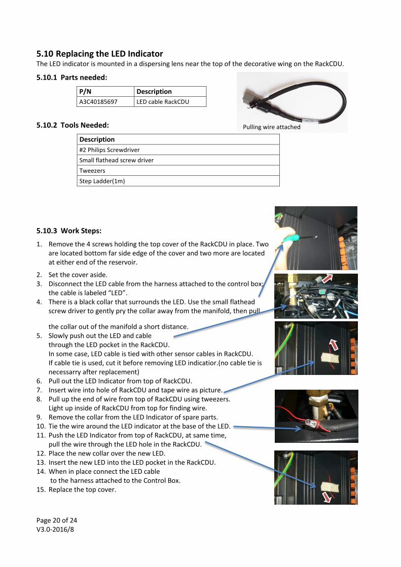
5.10 Replacing the LED Indicator The LED indicator is mounted in a dispersing lens near the top of the decorative wing on the RackCDU.
5.10.1 Parts needed:
P/N Description A3C40185697 LED cable RackCDU
5.10.2 Tools Needed:
Description #2 Philips Screwdriver Small flathead screw driver Tweezers Step Ladder(1m)
5.10.3 Work Steps:
1. Remove the 4 screws holding the top cover of the RackCDU in place. Two are located bottom far side edge of the cover and two more are located at either end of the reservoir.
2. Set the cover aside. 3. Disconnect the LED cable from the harness attached to the control box;
the cable is labeled “LED”. 4. There is a black collar that surrounds the LED. Use the small flathead
screw driver to gently pry the collar away from the manifold, then pull
the collar out of the manifold a short distance. 5. Slowly push out the LED and cable
through the LED pocket in the RackCDU. In some case, LED cable is tied with other sensor cables in RackCDU. If cable tie is used, cut it before removing LED indicatior.(no cable tie is necessarry after replacement)
6. Pull out the LED Indicator from top of RackCDU. 7. Insert wire into hole of RackCDU and tape wire as picture. 8. Pull up the end of wire from top of RackCDU using tweezers.
Light up inside of RackCDU from top for finding wire. 9. Remove the collar from the LED Indicator of spare parts. 10. Tie the wire around the LED indicator at the base of the LED. 11. Push the LED Indicator from top of RackCDU, at same time,
pull the wire through the LED hole in the RackCDU. 12. Place the new collar over the new LED. 13. Insert the new LED into the LED pocket in the RackCDU. 14. When in place connect the LED cable
to the harness attached to the Control Box. 15. Replace the top cover.
Pulling wire attached

Page 21 of 24 V3.0-2016/8
Page 22 of 24 V3.0-2016/8
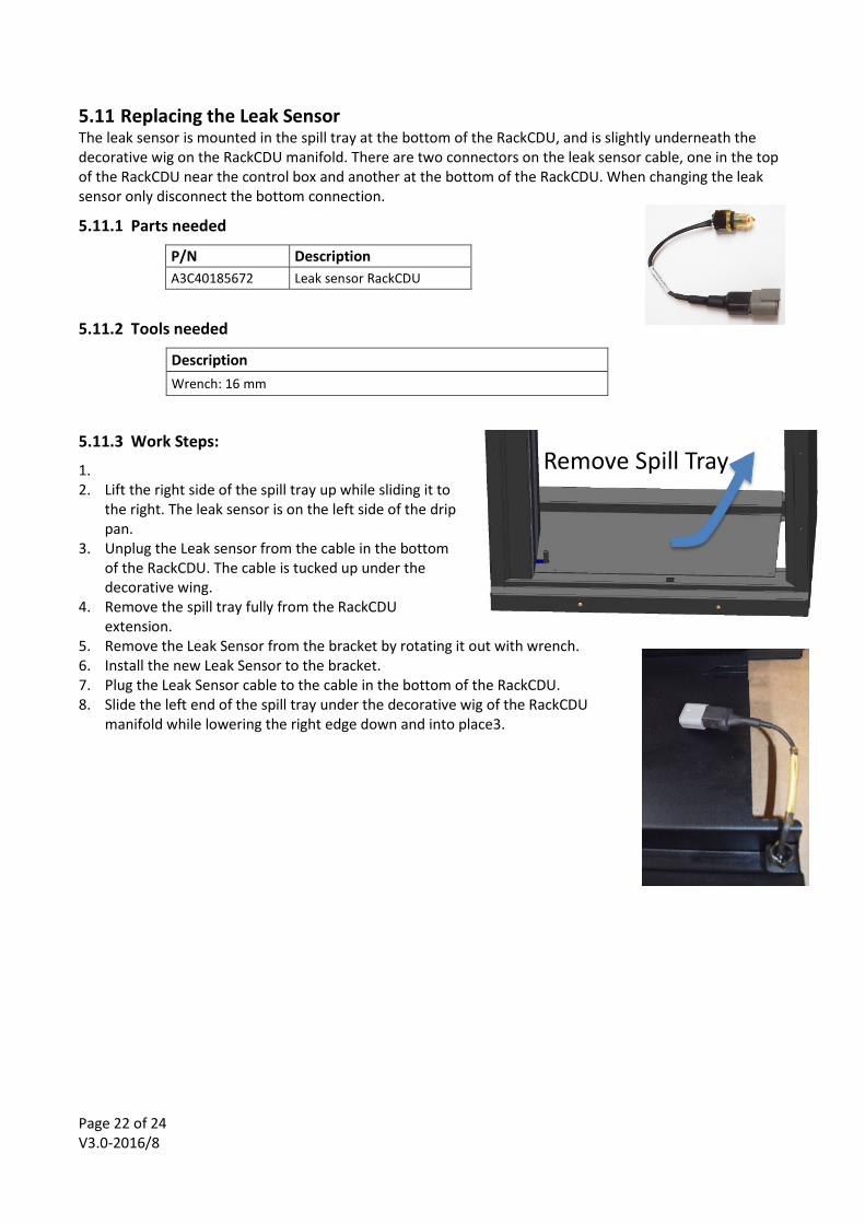
Remove Spill Tray
5.11 Replacing the Leak Sensor The leak sensor is mounted in the spill tray at the bottom of the RackCDU, and is slightly underneath the decorative wig on the RackCDU manifold. There are two connectors on the leak sensor cable, one in the top of the RackCDU near the control box and another at the bottom of the RackCDU. When changing the leak sensor only disconnect the bottom connection.
5.11.1 Parts needed
P/N Description A3C40185672 Leak sensor RackCDU
5.11.2 Tools needed
Description Wrench: 16 mm
5.11.3 Work Steps:
1. 2. Lift the right side of the spill tray up while sliding it to
the right. The leak sensor is on the left side of the drip pan.
3. Unplug the Leak sensor from the cable in the bottom of the RackCDU. The cable is tucked up under the decorative wing.
4. Remove the spill tray fully from the RackCDU extension.
5. Remove the Leak Sensor from the bracket by rotating it out with wrench. 6. Install the new Leak Sensor to the bracket. 7. Plug the Leak Sensor cable to the cable in the bottom of the RackCDU. 8. Slide the left end of the spill tray under the decorative wig of the RackCDU
manifold while lowering the right edge down and into place3.
Page 23 of 24 V3.0-2016/8
5.12 Replace Level Sensor The server coolant level sensor is connected to the server coolant reservoir located at the top of the RackCDU extension. The only service available for the sever coolant level sensor is to remove and replace it. This service requires shutting down all the servers attached to the RackCDU.
5.12.1 Parts needed
P/N Description A3C40185699 Level sensor RackCDU
5.12.2 Tools needed
Description #2 Philips Screwdriver
Step Ladder(1m)
Wrench, 24mm
Wrench: 16 mm
Low-sided Pan
Funnel with a small end opening of 18 mm or less
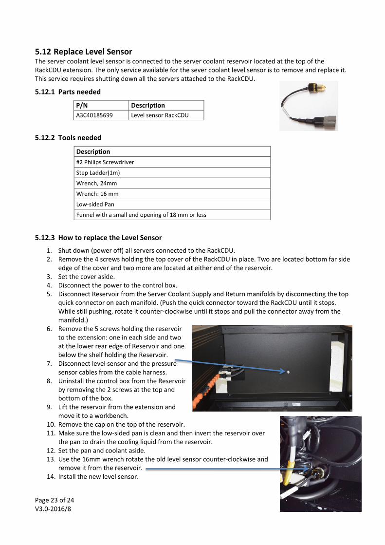
5.12.3 How to replace the Level Sensor
1. Shut down (power off) all servers connected to the RackCDU. 2. Remove the 4 screws holding the top cover of the RackCDU in place. Two are located bottom far side
edge of the cover and two more are located at either end of the reservoir. 3. Set the cover aside. 4. Disconnect the power to the control box. 5. Disconnect Reservoir from the Server Coolant Supply and Return manifolds by disconnecting the top
quick connector on each manifold. (Push the quick connector toward the RackCDU until it stops. While still pushing, rotate it counter-clockwise until it stops and pull the connector away from the manifold.)
6. Remove the 5 screws holding the reservoir to the extension: one in each side and two at the lower rear edge of Reservoir and one below the shelf holding the Reservoir.
7. Disconnect level sensor and the pressure sensor cables from the cable harness.
8. Uninstall the control box from the Reservoir by removing the 2 screws at the top and bottom of the box.
9. Lift the reservoir from the extension and move it to a workbench.
10. Remove the cap on the top of the reservoir. 11. Make sure the low-sided pan is clean and then invert the reservoir over
the pan to drain the cooling liquid from the reservoir. 12. Set the pan and coolant aside. 13. Use the 16mm wrench rotate the old level sensor counter-clockwise and
remove it from the reservoir. 14. Install the new level sensor.
Page 24 of 24 V3.0-2016/8
15. Use the funnel and return the coolant from the low-sided pan to the reservoir 16. Replace the cap screwing it fully into the reservoir with your fingers. 17. Reattach the reservoir to the RackCDU extension – five screws. 18. Connect the pressure sensor and level sensor cables to the harness. 19. Reinstall control box on Reservoir. 20. Reconnect power to the control box. 21. Replace the top cover. 22. Reconnect the Reservoir to the RackCDU by connecting the
Red Female Connector from the Reservoir to the top Red Male Connector on the RackCDU and the Blue Female Connector from the Reservoir to the top Blue Male Connector on the RackCDU.
23. Rotate the reservoir cap counter-clockwise until the line on the cap aligns with the “OPERATION” line on the top cover.
24. Power on all of the servers connected to the RackCDU.