Embed Size (px)
Citation preview

MPZ 001e
Handling, Installation, Operation &
Maintenance Instructions 4100-001-06.05 Department TB Page 1 24 Rev. Index B Name 01.06.05 Schell Date 01.01.09
Rack & Pinion Drives Released 01.06.05 Lorch
Drive Systems
Rack and Pinion Drives Operating Manual
© 2009 Atlanta Drive Systems Inc.

MPZ 001e
Handling, Installation, Operation &
Maintenance Instructions 4100-001-06.05 Department TB Page 2 24 Rev. Index B Name 01.06.05 Schell Date 01.01.09
Rack & Pinion Drives Released 01.06.05 Lorch
Table of Contents
Company Address ……………......…………………………………………………………. 3 General ………………...........................……………………………………………….……. 3
Safety Instructions, Signs & Symbols ...............……………………………………. 3 Exclusion of Liability ...................……………………………………………….……. 4
General Safety Instructions ……….………………………….……………………………. 4 Intended Use …………………………….…………..……………………………………….. 5 Improper Use …………………………..….……………………...………………………….. 6 Qualified Personnel …………………….….………….………...………………………….. 6 Rack Handling Safety ………………………………………….……………………………. 7 Transport and Handling …….……………………..………………….….………………… 8 Short Description …………….……………………………………………………..……….. 9 Rack Item Number …………...……..……………………………………………………….. 9 Storage …………………………………………………….…….……….………………….. 10 Installation Preparation ………………….…………………………………..……………. 10 Mounting Instructions ..………….….……………………………..….………….……….. 11
Rack Mounting to Contact Surface Only ….......……………….……………........ 11 Rack Mounting to Contact and Supporting Surfaces ………...........……………. 15
Mounting the Reducer …………………………………………….………………………. 17 Engaging the Reducer to the Rack ……………………………..………………………. 18 Final Inspection …………………………………………………………………………….. 19 Operating Conditions of Rack & Pinion …………………………….………………….. 19 Starting Automatic Lubrication System …..…………………...………...…………….. 20 Maintenance ……………………………………………………………………………….... 21
Taking Out of Operation, Preparation ………...…..……………………………..... 21 Inspection of Automatic Lubrication System …………….……………………...... 21
Restarting Operation After Maintenance ……...……………………………………….. 22 Troubleshooting ……………………..……………………………………………………... 22 Disassembly …………………………………………………………………...……………. 23
Preparation ……………………………………………………………..…………….. 23 Disassembling the Rack ……….….....………………………………………….….. 23
Lubricants ………………………………………………………………………..………….. 23 Lubrication of Rack and Pinion Drives …………………………………....……….. 23
Disposal …………………………………………………………………………..………….. 24
CAUTION! This operating manual is meant for all persons involved in the installation, operation and maintenance of ATLANTA Rack & Pinion Drives. To prevent damages and injuries, all instructions in this manual must be read and understood before any work is performed. This manual should be made accessible to all applicable personnel in a conspicuous fashion. Resellers & Buyers agree to also include this entire document to instruct Users on the safe and proper usage of the product. Observe any National / Regional regulations concerning safety and accident prevention.

MPZ 001e
Handling, Installation, Operation &
Maintenance Instructions 4100-001-06.05 Department TB Page 3 24 Rev. Index B Name 01.06.05 Schell Date 01.01.09
Rack & Pinion Drives Released 01.06.05 Lorch
Company Address:
ATLANTA Drive Systems Inc. Telephone (732) 282-0480 1775 Route 34, Unit D-10 Fax (732) 282-0450 Farmingdale, NJ 07727 E-Mail [email protected] USA Internet www.atlantadrives.com General:
This document is based on information available at the time of its publication. While efforts have been made to be accurate, the information contained herein does not purport to cover all details or variations, nor to provide for every possible contingency in connection with handling, installation, operation, or maintenance. Who Should Study These Instructions?
These instructions are addressed to all persons handling, installing, operating or maintaining the ATLANTA Rack & Pinion Drives. You must not use these drives before having read and understood all of these instructions. These instructions should be given to all applicable personnel and kept for future reference. Safety Instructions:
The following safety symbols and words are used throughout the instructions to warn and inform of a hazard:
Warns you about high injury hazards
Warns you about possible injury hazards
Warns you about minor injury and/or damage hazards
Transport: Warns you of injury hazards when transporting and handling of heavy and bulky objects.
Environmental Hazard: Warns you of a pollution hazard for the environment. Other Signs and Symbols Used in the Instructions:
☞ A “handling instruction“ in which you are asked to do something.
☺ A “suggestion“ shows you a possible simplification or improvement.
Maintenance: Suggests optimal operation.
Identification: Shows the description of the rack.
Storage: Informs about the correct storage of the racks.

MPZ 001e
Handling, Installation, Operation &
Maintenance Instructions 4100-001-06.05 Department TB Page 4 24 Rev. Index B Name 01.06.05 Schell Date 01.01.09
Rack & Pinion Drives Released 01.06.05 Lorch
General Safety Instructions:
The Rack & Pinion Drives incorporate the latest technological development at the time of delivery and can be principally regarded as safe to operate, but below instructions should be observed.
Improper performance of the work may cause personal injury and material damage.
☞ Installation, maintenance and disassembly of rack and pinion drive must only be carried
out by skilled personnel with the necessary knowhow and experience.
Contact with sharp edges may cause serious personal injury!
☞ Always wear safety helmet, goggles, protective gloves and safety shoes when handling this product.
Flying debris can cause grave personal injury and damages!
☞ Before starting the drive system, make sure there is no debris or tools nearby.
Contact with hot surfaces may cause burns!
☞ Never touch surfaces which have high operating temperatures. Use extreme care and suitable protective equipment (e.g. gloves)
Loose or incorrectly tightened screws can cause damage.
☞ Check that all screw connections are tightened to the recommended torque using a
calibrated torque wrench.
Moving and rotating machinery may cause personal injury by being caught or pulled into a machine!
☞ Do not wear loose or hanging clothing
☞ Keep a sufficient distance away from moving and rotating machinery.
☞ For safety, Buyer or User should provide protective safety guards for all moving
machinery. The User is responsible for checking all applicable local safety codes and providing suitable guards. Failure to do so may result in bodily injury and/or damage.
Unintentional machine starting during work can lead to serious injury! Insure lock-out/tag-out procedures are in place.
☞ Make sure that all safety devices are active and operational, and no one can start the
machine while people are working on it.
Never install or operate defective products.

MPZ 001e
Handling, Installation, Operation &
Maintenance Instructions 4100-001-06.05 Department TB Page 5 24 Rev. Index B Name 01.06.05 Schell Date 01.01.09
Rack & Pinion Drives Released 01.06.05 Lorch
☞ In case of defects seen in products, please contact ATLANTA immediately.
Lubricants are hazardous substances that can contaminate soil and water.
☞ Dispose of the lubricants as required by national regulations.
Exclusion of Liability: ATLANTA will not assume any liability for damage or injuries resulting from improper use or handling of the Rack & Pinion Drives. Buyer assumes all risk and liability for loss, damage or injury to persons or property of buyer or others arising out of use or possession of any product sold hereunder. Any improper use or handling not in accordance with these instructions may impair the quality of the product and will void any warranties contained herein. Modifications & Conversions: Modifications and/or conversions of the Rack & Pinion Drives are not permissible unless expressly approved by ATLANTA in writing. EC Machinery Directive: As defined by the EC Machinery Directive 98/37 EG, the Rack & Pinion Drives are not considered an autonomous machine but a component to be installed in machines. Within the purview of the EC directive, the Rack & Pinion Drives must not be operated unless the machine into which this product is installed fulfills the requirements of the directive. Technical Changes: ATLANTA Drive Systems Inc. reserves the right to make technical changes to improve the product without notice. Intended Use:
Rack & Pinion Drives must be used exclusively for converting rotary motion with torque into power-transmitting linear motion in machine
and plant construction applications under atmospheric conditions.
☞ The allowable load capacities are listed in our servo catalog or on our website:
www.atlantadrives.com
The Buyer shall be solely responsible for determining the adequacy of the Rack & Pinion Drives for any and all uses to which Buyer
shall apply the product.
The drive train containing the Rack & Pinion Drives must be free

MPZ 001e
Handling, Installation, Operation &
Maintenance Instructions 4100-001-06.05 Department TB Page 6 24 Rev. Index B Name 01.06.05 Schell Date 01.01.09
Rack & Pinion Drives Released 01.06.05 Lorch
from critical speed, torsional, or other type vibration, regardless of how induced. The Buyer shall be solely responsible for this analysis.
The Rack & Pinion Drives are not to be considered fail safe or self-locking devices & may drive from the output to the input. If these
features are required, a properly sized, independent holding device should be utilized.
Improper Use:
☞ Exceeding the permissible force and torque ratings shall be considered improper use
and is therefore prohibited.
☞ The machine design must be made strictly in accordance with our instructions. Any
deviation requires written approval by ATLANTA, otherwise this will be considered improper use and is prohibited.
☞ Wrong alignment (see section “Final Inspection“ on page 19) of the pinion with relation
to the rack shall be considered improper use and is therefore prohibited.
☞ Improper lubrication, e.g. lack of lubricant and/or use of a wrong lubricant, or insufficient
protection against pollution shall be considered improper use and is therefore prohibited.
☞ If several racks are mounted end-to-end, it must be assured that the pitch at the joints
lies within the permissible individual pitch error tolerances. Otherwise, this will be considered improper use and is prohibited.
Qualified Personnel:
Only skilled and trained personnel, being aware of the possible risks, may carry out mounting, installation, start-up, service, and maintenance work. The personnel must have the necessary qualifications for the work to be done and must be familiar with mounting, installation, start-up and operation of the product. The personnel must carefully read, understand and observe the operating instructions and, in particular, the safety instructions. They must also observe the applicable regional and national regulations on safety and accident prevention. The following work should only be carried out only by qualified personnel: transport, storage, installation, connection, start-up, service, maintenance.

MPZ 001e
Handling, Installation, Operation &
Maintenance Instructions 4100-001-06.05 Department TB Page 7 24 Rev. Index B Name 01.06.05 Schell Date 01.01.09
Rack & Pinion Drives Released 01.06.05 Lorch
Rack Handling Safety:
The racks must be assembled and installed only by skilled personnel having the necessary knowhow and experience.
☞ See section “Qualified Personnel” Always wear suitable safety helmet, goggles, protective gloves, and safety shoes when lifting rack out of its packing and handling it.
A second person should be called in or a crane be used, if the weight exceeds 20 lb. A second person should also be used if the rack length exceeds 1,000 mm, in order to prevent injury due to bad posture. The crane must always be operated by a crane driver. The rack to be carried must be properly secured and, if necessary, the ends of the rack marked in a clearly visible way.
☺ The table below shows the weight of the individual racks. The lengths are rounded to the nearest round length.
Mass of the Rack (in pounds)
Module 1 1.5 1.591 2 2.5 3 3.183 4 5 6 8 10
Length (mm)
200 - - - 1.9 - 2.7 - 6 6.6 10 21 24
250 0.9 1.1 0.9 2.2 2.4 3.5 3.4 6.2 7.6 10.6 24.4 -
500 1.8 2.3 1.7 4.9 4.9 7.1 7 12.5 15 23 50 -
1,000 3.6 4.5 3.4 9.7 9.7 14 14 25 29 55 99 155
1,500 - - - 13.5 - 21 - 37 45 67 - -
2,000 - 9 - 20 20 28 28 50 57 110 197 -
3,000 - - - 30 - 43 - 75 - - - -
When pivoting with a rack in hand, mark the pivoting radius with a warning sign and warning tape. This area must be blocked
during transport and handling so that no person may be endangered. Before starting transport of racks, make sure that the travel path is clean & clear, with ample room to maneuver with good footing.
Avoid twisting and bending while lifting or moving. Lift the racks comfortably and smoothly, keeping them close to the body.
Before starting transportation of racks, it must be ascertained that the overall dimensions of the rack permit safe handling. Never allow
the load to obstruct your view!
MPZ 001e
Handling, Installation, Operation &
Maintenance Instructions 4100-001-06.05 Department TB Page 8 24 Rev. Index B Name 01.06.05 Schell Date 01.01.09
Rack & Pinion Drives Released 01.06.05 Lorch
Always wear gloves when handling racks, because racks (especially those with helical teeth) have sharp edges. In order to avoid injury due to bad posture, the height of the mounting bench must be chosen in such a way that it suits the
height of the mechanic. An adjustable mounting bench would be needed if mechanics of different height were to work at the same bench.
Suitable supports or trestles must be provided in order to prevent hand or fingers from being squeezed and bruised when placing the
rack onto the bench or table. It is also important to consider the center of gravity of the rack when setting it down because it could tilt or fall, resulting in injury of
persons nearby. A suitable support should also be provided when placing the racks to avoid excessive bending.
For tightening of the screws, a suitable working height should be chosen for the mechanic. Furthermore it is important to choose a
suitable screwdriver to avoid wrist injury. The work surroundings must be perfectly prepared for this process in order to avoid injury while working.
If rack contact occurs without gloves, wash your hands immediately because the racks are oiled. Always wear protective gloves when
handling racks!
Rack Transport:
☞ Please observe the instructions in the section “Rack Handling Safety”
☞ Observe all safety regulations for transport & handling with cranes, hoists & forklifts.
☞ Make sure that the load is handled and set down slowly and carefully.
☞ Especially when transporting and handling long racks ( 2 meters), avoid any leverage
upon the rack. Recommended lever arm ratios are as shown below:
☞ If necessary, have one or more persons lend a hand.

MPZ 001e
Handling, Installation, Operation &
Maintenance Instructions 4100-001-06.05 Department TB Page 9 24 Rev. Index B Name 01.06.05 Schell Date 01.01.09
Rack & Pinion Drives Released 01.06.05 Lorch
Short Description: Rack and Pinion Drives convert rotary motion and torque of a gear into the power-transmitting linear motion of a gear rack. This takes place when the operating pitch diameter of the gear meshes with the common pitch line of the rack without slipping. At the point of contact, the peripheral speed of both operating pitch diameters is identical. Racks are available in different quality levels, to be chosen by the customer to suit the intended use. Rack Item Number:
☺ The item number A) is located on the rack.
☺ Example: Racks for continuous linking.
Identification:
☞ The rack is identified by item number as well as the manufacturer’s logo and manufacturing lot number.
Quality and Precision
Module With Mounting Holes Length of Rack

MPZ 001e
Handling, Installation, Operation &
Maintenance Instructions 4100-001-06.05 Department TB Page 10 24 Rev. Index B Name 01.06.05 Schell Date 01.01.09
Rack & Pinion Drives Released 01.06.05 Lorch
Storage: If the rack is not going to be installed immediately after delivery, the following measures should be taken:
☞ Store the racks in a cool and dry place and in such a way that they don’t come into
contact with any other objects.
☞ Avoid any metal-to-metal contacts between the racks during storage. Put a layer of protective foil or oil paper between them.
☞ Protect the racks against corrosion. Remove the anti-corrosive agent only immediately
before the installation. When storing for a period of more than one month, add an anti-corrosive coating.
☞ Protect the racks against environmental influences (ozone, UV light, electric welding, dust, dirt, moisture, temperature fluctuations (32°F to +86°F), shocks, etc.).
☞ Avoid any unfavorable leverage on the rack during storage (for lever ratios, see section
“Rack Transport”).
☞ Protect the rack against dust or other pollution.
☞ Take care to not damage the teeth or the supporting/contact surfaces.
☞ For store keeping, we recommend a “First In - First Out” principle.
Installation Preparation:
☞ Re-read the sections “General Safety Instructions” and “Rack Handling Safety”
☞ Set your torque wrench and check its function.
☞ Wear protective gloves while assembling in order to avoid contact corrosion.
☞ Inspect the racks for external damage and cleanliness.
☞ A damaged or dirty rack must not be mounted or operated. The contact surfaces and,
if necessary, supporting surfaces, are to be carefully wiped off with a clean rag.

MPZ 001e
Handling, Installation, Operation &
Maintenance Instructions 4100-001-06.05 Department TB Page 11 24 Rev. Index B Name 01.06.05 Schell Date 01.01.09
Rack & Pinion Drives Released 01.06.05 Lorch
Mounting Instructions:
☞ Please observe the instructions in the sections “General Safety Instructions” and
“Rack Handling Safety” Rack Mounting to Contact Surface Only:
Socket Head Cap Screws, Class 12.9 M6 M8 M12 M16 M20 M30 Tightening torque (lb.ft.) 11.8 29.5 99.6 251 487 1,696
2. Place the mating companion rack across the rack joint so that it meshes with the
teeth of the two racks and clamp it on the opposite side using a suitable clamping surface.
Contact surface
No supporting surface available fl h h d
Mating piece
Suitable clamping surface
1. Position the first rack in the center of the machine bed and clamp it to the contact surface with a screw clamp. Insert the socket head cap screws & tighten them slightly. Adjust the supporting surface of the rack in relation to the machine guide. Then tighten the socket head cap screws as shown in the torque table below, beginning with the screw in the middle of the rack and continue outwards. Once this is done, the screw clamps may be removed.
Fit the second rack at the end of the first and clamp it with screw clamps against the contact surface of the machine bed. Insert the socket head cap screws and tighten them slightly so that rack axial movement is still possible. Once this is done, the screw clamps may be removed.

MPZ 001e
Handling, Installation, Operation &
Maintenance Instructions 4100-001-06.05 Department TB Page 12 24 Rev. Index B Name 01.06.05 Schell Date 01.01.09
Rack & Pinion Drives Released 01.06.05 Lorch
☺ Mounting example on the machine bed
3. Remove the mating companion rack and the suitable clamping surface.
4. Exact alignment of the racks at the joint is obtained with the aid of a mounting set consisting of an adjustment tool, three magnetic measuring pins, a measuring bridge with dial gauge, and a hex wrench.
☺ Suitable set sizes and descriptions can be taken from our servo catalog or our website: www.atlantadrives.com.
5. Put the measuring bridge on a smooth-ground surface and set the dial gauge to
zero.
Zero Setting

MPZ 001e
Handling, Installation, Operation &
Maintenance Instructions 4100-001-06.05 Department TB Page 13 24 Rev. Index B Name 01.06.05 Schell Date 01.01.09
Rack & Pinion Drives Released 01.06.05 Lorch
6. Plug the adjustment tool into the dowel holes at the joint of the two racks. One
measuring pin is laid into the tooth gap at the joint and the other two in a tooth gap left and right of the joint. Position the measuring bridge on the pins so that the tip of the dial gauge touches the middle pin. Find the high point by moving side-to-side.
7. Using a hex wrench, adjust the screw of the adjustment tool so the rack, which is not yet firmly mounted, can be moved to the left or the right until the dial gauge reaches the zero position again.
Permissible deviations, in millimeters, measured with the mounting set:
Module
Quality 2 3 4 5 6 8 10
DIN 4 - - ±0.004 ±0.004 ±0.004 ±0.004
DIN 6 ±0.01 ±0.011 ±0.011 ±0.016 ±0.016 ±0.014 ±0.015
DIN 7 - - - - - - -
DIN 8 ±0.027 ±0.03 ±0.032 ±0.033 - - -
DIN 9 ±0.027 ±0.03 ±0.032 ±0.033 ±0.036 ±0.038 ±0.041
DIN 10 ±0.041 ±0.042 ±0.045 ±0.047 ±0.049 - -

MPZ 001e
Handling, Installation, Operation &
Maintenance Instructions 4100-001-06.05 Department TB Page 14 24 Rev. Index B Name 01.06.05 Schell Date 01.01.09
Rack & Pinion Drives Released 01.06.05 Lorch
8. Slightly tighten the socket head cap screws on the not yet fully fixed rack. Then loosen the screw on the adjustment tool and remove it from the dowel holes of the racks.
9. Using a torque wrench, tighten the socket head cap screws as shown in the torque
table on page 11, one after the other starting in the middle of the rack and continuing outwards.
10. Check the pitch once more and repeat steps 5 to 9, if necessary.
11. Racks shorter than 1 meter must be pinned at the dowel holes.
Pinning
☞ Clamp the rack with screw clamps at all
dowel holes as shown in the picture.
☞ Drill the dowel holes into the machine bed to match the holes in the rack.
☞ Ream each pair of holes simultaneously to the required tolerance fit H7 for the dowel pins.
☞ Now fix the racks permanently with the
dowel pins.

MPZ 001e
Handling, Installation, Operation &
Maintenance Instructions 4100-001-06.05 Department TB Page 15 24 Rev. Index B Name 01.06.05 Schell Date 01.01.09
Rack & Pinion Drives Released 01.06.05 Lorch
Mating piece Clamping device
☺ In the case of racks of 1 meter length or more, the dowel pins are only needed for fixing, i.e. the dowel pins are not really necessary if the rack is not going to be removed again for shipping.
Rack Mounting to Contact and Supporting Surfaces: 1. Position the first rack on the machine bed against the contact surface and the supporting surface, and then clamp it with screw clamps. Next insert the socket head cap screws and tighten them according to the torque table on page 11, starting in the middle of the rack and continuing outwards. Position the second rack at the end of the first and clamp it with screw clamps to the contact and supporting surfaces of the machine bed. Insert the socket head cap screws and tighten them slightly so that the racks can still be moved axially. Once this is done, the screw clamps may be removed. 2. Insert the mating companion rack over the joint so that it meshes with the teeth of the two racks and clamp it with a suitable clamping device on the supporting surface. 3. Tighten the socket head cap screws of the second rack in such a way that axial adjustment is still possible. Once this is done, the companion rack can be removed.
The rack has a chamfer between contact surface and supporting surface in order to assure a perfect fit in the machine bed. The machine bed should be designed such that easy mounting of the rack is possible.

MPZ 001e
Handling, Installation, Operation &
Maintenance Instructions 4100-001-06.05 Department TB Page 16 24 Rev. Index B Name 01.06.05 Schell Date 01.01.09
Rack & Pinion Drives Released 01.06.05 Lorch
☺ The following is a mounting example on the machine bed Steps 4 to 10 are the same as with the mounting instructions with the contact surface only. Pinning
☺ In the case of racks of 1 meter length or more the dowel pins are only needed for fixing,
i.e. the dowel pins are not really necessary if the rack is not going to be removed again for shipping.
☞ Clamp the rack with screw clamps at
all dowel holes as shown in the picture.
☞ Drill the dowel holes into the machine bed according to the holes in the rack.
☞ Ream the drilled holes together to the tolerance fit H7 for the dowel pins.
☞ Now secure the rack permanently
with dowel pins

MPZ 001e
Handling, Installation, Operation &
Maintenance Instructions 4100-001-06.05 Department TB Page 17 24 Rev. Index B Name 01.06.05 Schell Date 01.01.09
Rack & Pinion Drives Released 01.06.05 Lorch
Mounting the Reducer:
In the case of Z axis (vertical orientation), the machine table must be properly secured before connecting it with rack and reducer.
Otherwise it could roll off due to its own weight and cause personal injury and material damage.
☞ Mount the reducer temporarily on
the machine table and slightly tighten the mounting screws (do not tighten them fully!). Mounting example: see picture.
Before mounting the reducer on the machine table, the pinion shaft and lubricator (see separate instructions) should be mounted. The machine table must be designed in such a way that the reducer can be readily mounted and adjusted. An example is shown on the picture below.

MPZ 001e
Handling, Installation, Operation &
Maintenance Instructions 4100-001-06.05 Department TB Page 18 24 Rev. Index B Name 01.06.05 Schell Date 01.01.09
Rack & Pinion Drives Released 01.06.05 Lorch
Engaging the Reducer to the Rack:
☞ Please observe the instructions in the section “General Safety Instructions”
☞ Before the pinion is engaged to the rack, the high point of the rack must be found. When the pinion is meshed at the high point of the rack, no binding will happen on the rest of the travel length. First, a dial indicator must be attached to the carriage. Starting at the end of travel, place a pin in the rack teeth and position the dial indicator over it and set the indicator to zero. Next, move the carriage to the next measuring position and note the dial indicator reading. Repeat this process over the full travel length until the high point of the rack is located and marked.
☞ At the high point of the rack determined from above, push the reducer manually into the
rack until the pinion meshes with a small amount of backlash. Then tighten slightly the mounting screws of the reducer.
☞ The carriage with the reducer and pinion should be moved back and forth over the full
travel length to confirm smooth operation. At the low point of the rack, there will be more backlash at the pinion, which depends on the quality of rack and pinion used. Depending upon the quality of the rack, the backlash can vary more or less.
☺ To achieve movement free from backlash over the full travel length, we recommend replacing the pinion shaft inside the reducer with a pre-load split-pinion shaft. The mounting and adjusting instructions for this item, as well as the torque to be transmitted, can be found in our servo catalog.

MPZ 001e
Handling, Installation, Operation &
Maintenance Instructions 4100-001-06.05 Department TB Page 19 24 Rev. Index B Name 01.06.05 Schell Date 01.01.09
Rack & Pinion Drives Released 01.06.05 Lorch
Final Inspection:
☞ Remove the grease from the rack and pinion tooth flanks.
☞ Coat the tooth flanks with marking/bluing compound.
☞ Move the table back-and-forth several times so that the pinion runs over the coated tooth flanks to transfer the compound.
☞ At the same time, check the smooth operation of the rack & pinion. The power required and the running noise must remain the same over the full travel length. Also, there must not be any rough spots at the rack joints.
☞ Check the area where the marking compound rubbed off from the tooth flanks and
compare it to the following sketches.
☞ If necessary, correct the alignment of the reducer and pinion to the rack.
☞ When the alignment of the rack & pinion and reducer is correct, permanently mount
the reducer to the machine.
☞ Check the racks at the joint for precision of pitch. Operating Conditions of Rack & Pinion:
☞ Please observe the instructions in the section “General Safety Instructions”
Lacking or insufficient lubrication leads to damage to the teeth. Unlubricated start-up can cause immediate damage.
☞ Ensure proper lubrication along the rack & pinion when first starting up machine.
☞ Ensure continuous lubrication and replacement schedule of the lubricator.
☞ Pay close attention to the correct meshing of pinion and rack.
☞ For X and Y axis (horizontal installation without reducer), it should be possible to move the freewheeling machine table by hand uniformly over the full travel length (while checking for binding-free installation). In the case of Z axis (vertical installation) the machine table must be properly secured.
Correct Not at right angles
Not parallel
Wrong center distances
Correct

MPZ 001e
Handling, Installation, Operation &
Maintenance Instructions 4100-001-06.05 Department TB Page 20 24 Rev. Index B Name 01.06.05 Schell Date 01.01.09
Rack & Pinion Drives Released 01.06.05 Lorch
Starting Automatic Lubrication System:
☞ Before switching on the lubricator, make sure that the hose is filled, without any air
bubbles, and that the felt gear is soaked with the suitable lubricant.
☺ Information on the mounting dimensions, mounting positions and type of lubricant can be seen in our servo catalog or our website www.atlantadrives.com.
☺ If the lubricator cannot be installed as shown above, the individual components can also be used without the mounting bracket. In this case, the attachment of the mounting shaft with the felt gear and the lubricator must be mounting separately.
☞ Please be aware that in the case of grease lubrication, the hose must not be longer than
1.5 meters (5 feet). Before starting up the lubricator, there must not be any kinks in the hose and the hose must be filled with the suitable lubricant without any air bubbles. Furthermore, the felt gear must also be soaked with the suitable lubricant.
☞ The center distance “a“ between pinion and felt gear is calculated by the following formula:
a = 2
FR dd dR – pitch diameter of pinion; dF – pitch diameter of felt gear
☞ The center distance “a“ between rack and felt gear is calculated by the following formula:
a = h0 x 2Fd
h0 – pitch height of rack; dF – pitch diameter of felt gear
☺ Further information on the proper start-up of the whole lubricating system are contained in the operating instructions BKI 101; BKI 102; BKI 104, and BKI 105.
☺ The automatic lubrication system consists of a mounting bracket, an electronically-controlled lubricator, a connecting hose, a mounting shaft, and a felt gear. Depending upon the mounting position on the reducer, the felt gear can be fixed on the mounting bracket in various positions.
☞ When mounting the lubricator on the reducer, make sure that the teeth of the felt gear mesh correctly with the teeth of the pinion shaft. Using the rectangular slots provided in the mounting bracket, the lubricator assembly can be adjusted on the reducer.

MPZ 001e
Handling, Installation, Operation &
Maintenance Instructions 4100-001-06.05 Department TB Page 21 24 Rev. Index B Name 01.06.05 Schell Date 01.01.09
Rack & Pinion Drives Released 01.06.05 Lorch
Maintenance: Taking Out of Operation, Preparations
☞ Please observe the instructions in the sections “General Safety Instructions” and “Rack Handling Safety”
☞ The machine which uses the rack and pinion drive must be shut down.
☞ Before any work begins, the machine power supply must be disconnected.
☞ In the case of Z axis (vertical installation), the machine table must be properly secured. When disassembling the racks and reducer, the positive connection to the machine table is interrupted. If the machine table on a Z-axis
(vertical installation) is not properly secured, it can roll off due to its own weight and cause personal injury and material damage. Visual check
☞ The entire drive system must be visually checked for external damage and leakage.
☞ Any defective or leaking components should be repaired immediately. For the reducer, please also observe the following operating and maintenance instructions:
☺ HT Servo-Worm Reducers BWS 113
☺ HP Servo-Worm Reducers BWS 107-10
☺ E Servo-Worm Reducers BWS 110
☺ B Servo-Worm Reducers BWS 112
☞ Clean the rack and pinion.
Inspection of Automatic Lubrication System:
☺ The felt gear must never be exposed to ambient temperatures over 70°C (158°F).
☺ The lubricant level can be seen through the transparent housing.
☞ Thorough visual inspection for externally damage such as loosened, kinked or defective hose, worn or soiled felt gear, and for proper functioning of the lubricator.
☞ Any defective, soiled or non-functioning components
should be replaced immediately. The service life of the felt gear depends upon the ambient conditions.
☺ When working under polluted ambient conditions, we recommend to shorten the inspection intervals.
MPZ 001e
Handling, Installation, Operation &
Maintenance Instructions 4100-001-06.05 Department TB Page 22 24 Rev. Index B Name 01.06.05 Schell Date 01.01.09
Rack & Pinion Drives Released 01.06.05 Lorch
Please also observe the operating and maintenance instructions BKI 101; BKI 102; BKI 103; BKI 104; BKI 105, and BKI 106 for the lubricator. Restarting Operation After Maintenance:
☞ Reinstall all safety devices and confirm their operation.
☞ In the case of Z axis (vertical installation), check the connection between machine table, rack and reducer and unlock the machine table.
☞ Before releasing the machine again for operation, re-read the instructions in the
section “Operating Conditions of Rack & Pinion” and then perform a test run.
☞ Look for any forgotten screws and tools and remove them.
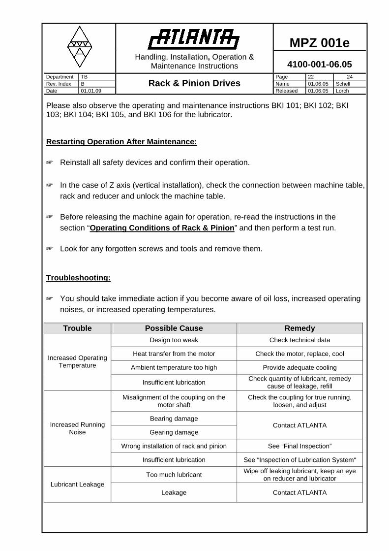
Troubleshooting:
☞ You should take immediate action if you become aware of oil loss, increased operating
noises, or increased operating temperatures.
Trouble Possible Cause Remedy
Design too weak Check technical data
Heat transfer from the motor Check the motor, replace, cool
Ambient temperature too high Provide adequate cooling
Increased Operating Temperature
Insufficient lubrication Check quantity of lubricant, remedy
cause of leakage, refill
Misalignment of the coupling on the motor shaft
Check the coupling for true running, loosen, and adjust
Bearing damage
Gearing damage Contact ATLANTA
Wrong installation of rack and pinion See “Final Inspection”
Increased Running Noise
Insufficient lubrication See “Inspection of Lubrication System“
Too much lubricant Wipe off leaking lubricant, keep an eye
on reducer and lubricator Lubricant Leakage
Leakage Contact ATLANTA

MPZ 001e
Handling, Installation, Operation &
Maintenance Instructions 4100-001-06.05 Department TB Page 23 24 Rev. Index B Name 01.06.05 Schell Date 01.01.09
Rack & Pinion Drives Released 01.06.05 Lorch
Disassembly:
Improper performance of the work may cause personal injury and material damage.
☞ Please observe the instructions in the section “General Safety Instructions” and “Rack Handling Safety”
☞ The disassembly of Rack & Pinion Drive may be carried out only by skilled personnel with the necessary knowhow and experience. See section “Qualified Personnel”.
Preparation
☞ The machine which uses the rack & pinion drive must be shut down.
☞ Ensure that the drive system can be removed without damage to the machine.
☞ Before any work begins, the machine power supply must be disconnected.
☞ In the case of Z axis (vertical installation), the machine table must be properly secured. When disassembling the racks and reducers, the positive connection to the machine table is interrupted. If the machine table on a Z-axis
(vertical installation) is not properly secured, it can roll off due to its own weight and cause personal injury and material damage. Disassembling the Rack
☞ All mounting screws must be loosened before the rack can be removed from the dowel pins with the aid of suitable tools.
☞ Remove the racks carefully in order to avoid damage to the drive system and adjoining
components. Lubricants: Lubrication of Rack and Pinion Drives:
For the continuous lubrication of Rack & Pinion Drives, we recommend to using ATLANTA electronically-controlled
lubricators together with felt gear or the sliding brush applicators. Item numbers and descriptions are contained in our servo catalog or on our website: www.atlantadrives.com. Recommended grease lubricants are the following:
☺ Klüber Microlube GB 0 Order code 65 90 002 (1 kg)

MPZ 001e
Handling, Installation, Operation &
Maintenance Instructions 4100-001-06.05 Department TB Page 24 24 Rev. Index B Name 01.06.05 Schell Date 01.01.09
Rack & Pinion Drives Released 01.06.05 Lorch
☺ Klüber Structovis AHD Order code. 65 90 003 (1 kg)
The following lubricants have also been tested with good results:
☺ Oest Langzeitfett LT 200
☺ BP Energrease LS EP 00
☺ DEA Glissando 6833 EP 00
☺ Fuchs Lubritech Gearmaster ZSA
☺ Molykote G-Rapid plus 3694 Disposal: Lubricants
Lubricants are hazardous substances that can contaminate soil and water.
☞ Dispose of the lubricants as required by national regulations.
☞ Never mix polyglycolic substances with mineral oils which are intended for recycling.
Seals
☞ Seals are to be disposed of as compound materials (metal/plastics).
Metal
☞ The drive components are to be separated as follows:
Iron Aluminium (housings, covers) Non-ferrous metal (worm gears; motor windings)
Hoses
☞ Hoses are to be disposed of as plastic materials.
Felt Gears
☞ Felt gears can be disposed of as residual waste.
ATLANTA will not assume any liability for damage or injuries resulting from
improper use or handling of the Rack & Pinion Drives. Buyer assumes all risk and liability for loss, damage or injury to persons or property of buyer or others arising out of use or possession of any product sold hereunder. Any improper
use or handling not in accordance with these instructions may impair the quality of the product and will void any warranties contained herein.


![MPZ 0 2 - IAG webbutiken... · 2020. 6. 23. · 726 MPZ 0 2 Gripping force, O.D. gripping e c nr g o pf pi i Gr F [N] L [mm] MPZ 20 / 4 bar MPZ 20 / 6 bar MPZ 20-AS / 4 bar MPZ 20-AS](https://img.pdfslide.us/doc/110x75/5fd0918bffd3e827f63fb4bf/mpz-0-2-webbutiken-2020-6-23-726-mpz-0-2-gripping-force-od-gripping.jpg)