Embed Size (px)
DESCRIPTION
Citation preview
���
Rack Installation Instructions for IBM Gen-III Slides Kit
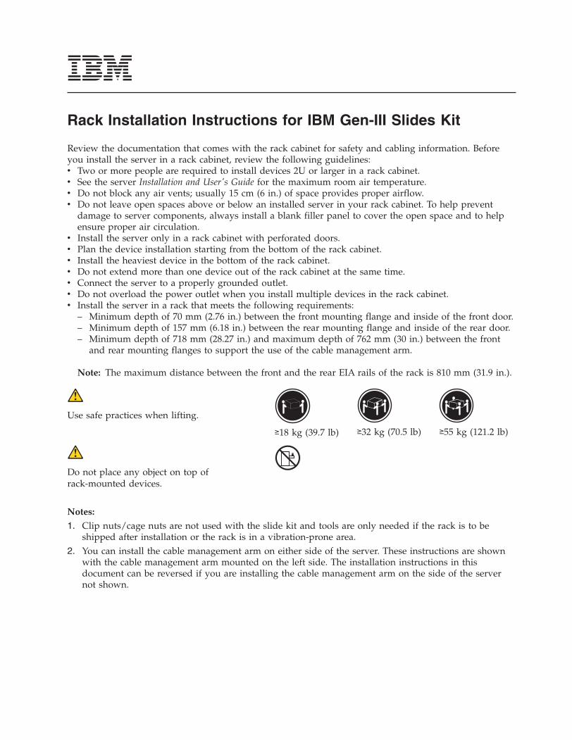
Review the documentation that comes with the rack cabinet for safety and cabling information. Beforeyou install the server in a rack cabinet, review the following guidelines:v Two or more people are required to install devices 2U or larger in a rack cabinet.v See the server Installation and User's Guide for the maximum room air temperature.v Do not block any air vents; usually 15 cm (6 in.) of space provides proper airflow.v Do not leave open spaces above or below an installed server in your rack cabinet. To help prevent
damage to server components, always install a blank filler panel to cover the open space and to helpensure proper air circulation.
v Install the server only in a rack cabinet with perforated doors.v Plan the device installation starting from the bottom of the rack cabinet.v Install the heaviest device in the bottom of the rack cabinet.v Do not extend more than one device out of the rack cabinet at the same time.v Connect the server to a properly grounded outlet.v Do not overload the power outlet when you install multiple devices in the rack cabinet.v Install the server in a rack that meets the following requirements:
– Minimum depth of 70 mm (2.76 in.) between the front mounting flange and inside of the front door.– Minimum depth of 157 mm (6.18 in.) between the rear mounting flange and inside of the rear door.– Minimum depth of 718 mm (28.27 in.) and maximum depth of 762 mm (30 in.) between the front
and rear mounting flanges to support the use of the cable management arm.
Note: The maximum distance between the front and the rear EIA rails of the rack is 810 mm (31.9 in.).
Use safe practices when lifting.
≥18 kg (39.7 lb) ≥32 kg (70.5 lb) ≥55 kg (121.2 lb)
Do not place any object on top ofrack-mounted devices.
Notes:
1. Clip nuts/cage nuts are not used with the slide kit and tools are only needed if the rack is to beshipped after installation or the rack is in a vibration-prone area.
2. You can install the cable management arm on either side of the server. These instructions are shownwith the cable management arm mounted on the left side. The installation instructions in thisdocument can be reversed if you are installing the cable management arm on the side of the servernot shown.
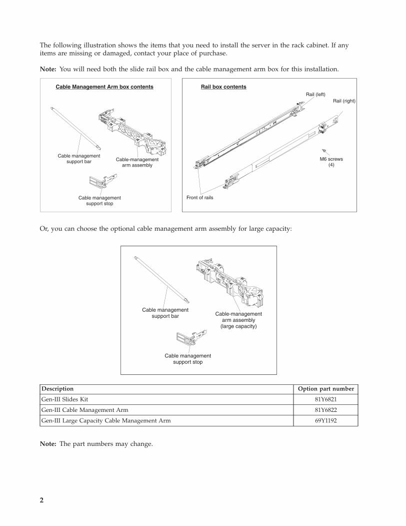
The following illustration shows the items that you need to install the server in the rack cabinet. If anyitems are missing or damaged, contact your place of purchase.
Note: You will need both the slide rail box and the cable management arm box for this installation.
M6 screws(4)
Rail (right)Rail (left)
Cable-managementarm assembly
Front of rails
Cable managementsupport bar
Cable Management Arm box contents Rail box contents
Cable managementsupport stop
Or, you can choose the optional cable management arm assembly for large capacity:
Cable-managementarm assembly
(large capacity)
Cable managementsupport bar
Cable managementsupport stop
Description Option part number
Gen-III Slides Kit 81Y6821
Gen-III Cable Management Arm 81Y6822
Gen-III Large Capacity Cable Management Arm 69Y1192
Note: The part numbers may change.
2
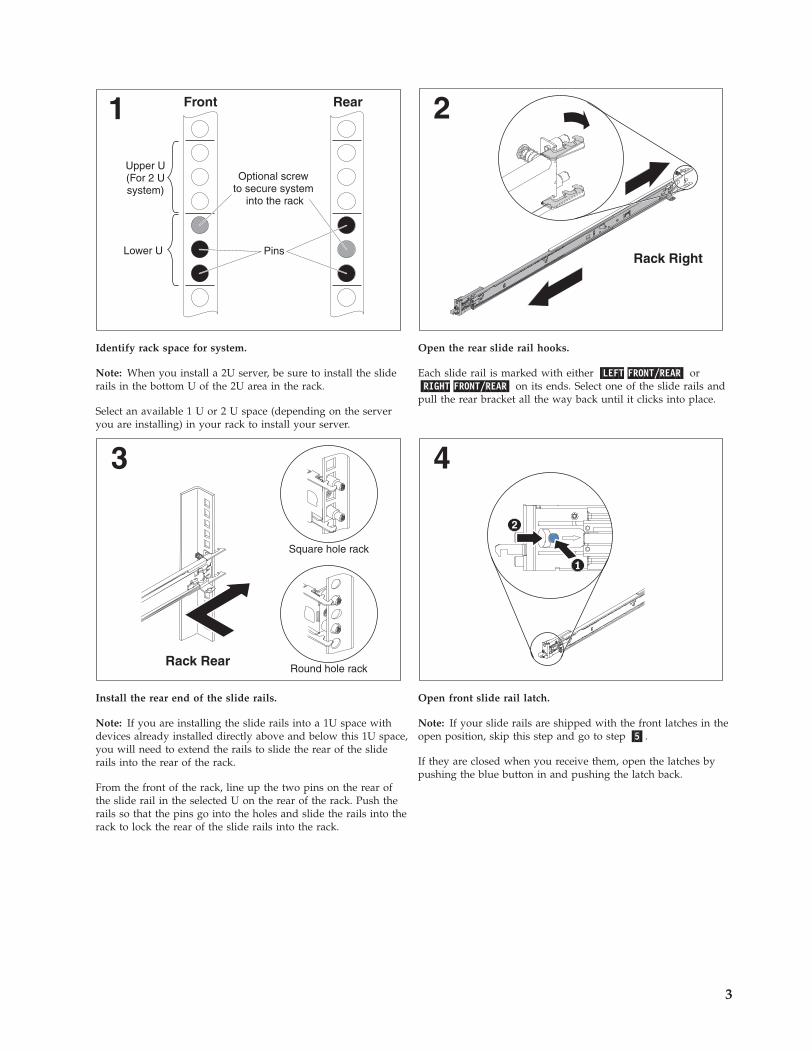
1 Front Rear
Upper U(For 2 Usystem)
Lower U
Optional screwto secure system
into the rack
Pins
2
Rack Right
Identify rack space for system.
Note: When you install a 2U server, be sure to install the sliderails in the bottom U of the 2U area in the rack.
Select an available 1 U or 2 U space (depending on the serveryou are installing) in your rack to install your server.
Open the rear slide rail hooks.
Each slide rail is marked with either �LEFT FRONT/REAR� or�RIGHT FRONT/REAR� on its ends. Select one of the slide rails andpull the rear bracket all the way back until it clicks into place.
3
Rack Rear
Square hole rack
Round hole rack
4
2
Install the rear end of the slide rails.
Note: If you are installing the slide rails into a 1U space withdevices already installed directly above and below this 1U space,you will need to extend the rails to slide the rear of the sliderails into the rear of the rack.
From the front of the rack, line up the two pins on the rear ofthe slide rail in the selected U on the rear of the rack. Push therails so that the pins go into the holes and slide the rails into therack to lock the rear of the slide rails into the rack.
Open front slide rail latch.
Note: If your slide rails are shipped with the front latches in theopen position, skip this step and go to step �5�.
If they are closed when you receive them, open the latches bypushing the blue button in and pushing the latch back.
3
5
Rack Front
6
Rack Front
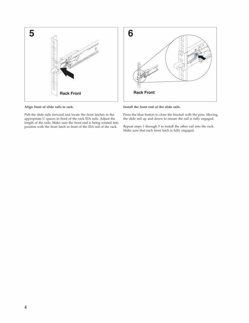
Align front of slide rails to rack.
Pull the slide rails forward and locate the front latches in theappropriate U spaces in front of the rack EIA rails. Adjust thelength of the rails. Make sure the front end is being rotated intoposition with the front latch in front of the EIA rail of the rack.
Install the front end of the slide rails.
Press the blue button to close the bracket with the pins. Movingthe slide rail up and down to ensure the rail is fully engaged.
Repeat steps 1 through 5 to install the other rail into the rack.Make sure that each front latch is fully engaged.
4
7
Lift point
Lift point
2
3
8
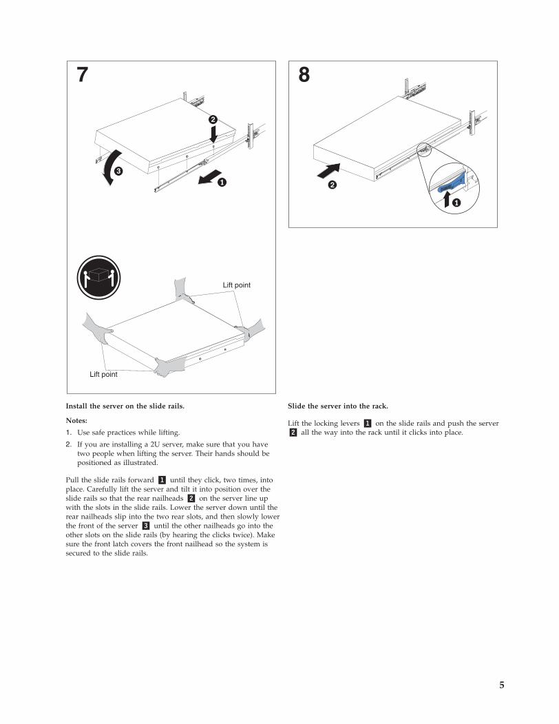
Install the server on the slide rails.
Notes:
1. Use safe practices while lifting.
2. If you are installing a 2U server, make sure that you havetwo people when lifting the server. Their hands should bepositioned as illustrated.
Pull the slide rails forward �1� until they click, two times, intoplace. Carefully lift the server and tilt it into position over theslide rails so that the rear nailheads �2� on the server line upwith the slots in the slide rails. Lower the server down until therear nailheads slip into the two rear slots, and then slowly lowerthe front of the server �3� until the other nailheads go into theother slots on the slide rails (by hearing the clicks twice). Makesure the front latch covers the front nailhead so the system issecured to the slide rails.
Slide the server into the rack.
Lift the locking levers �1� on the slide rails and push the server�2� all the way into the rack until it clicks into place.
5
9
Rack Rear
2
10
2
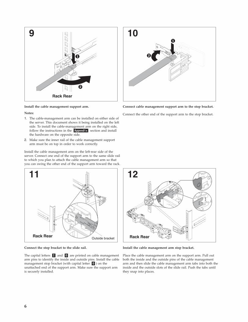
Install the cable management support arm.
Notes:
1. The cable-management arm can be installed on either side ofthe server. This document shows it being installed on the leftside. To install the cable-management arm on the right side,follow the instructions in the �Appendix� section and installthe hardware on the opposite side.
2. Make sure the inner rail of the cable management supportarm must be on top in order to work correctly.
Install the cable management arm on the left-rear side of theserver. Connect one end of the support arm to the same slide railto which you plan to attach the cable management arm so thatyou can swing the other end of the support arm toward the rack.
Connect cable management support arm to the stop bracket.
Connect the other end of the support arm to the stop bracket.
11
Rack RearOutside bracket
12
Rack Rear
Connect the stop bracket to the slide rail.
The capital letters �I� and �O� are printed on cable managementarm pins to identify the inside and outside pins. Install the cablemanagement stop bracket (with capital letter �O�) on theunattached end of the support arm. Make sure the support armis securely installed.
Install the cable management arm stop bracket.
Place the cable management arm on the support arm. Pull outboth the inside and the outside pins of the cable managementarm and then slide the cable management arm tabs into both theinside and the outside slots of the slide rail. Push the tabs untilthey snap into places.
6
13
Rack Rear Rack Rear
14
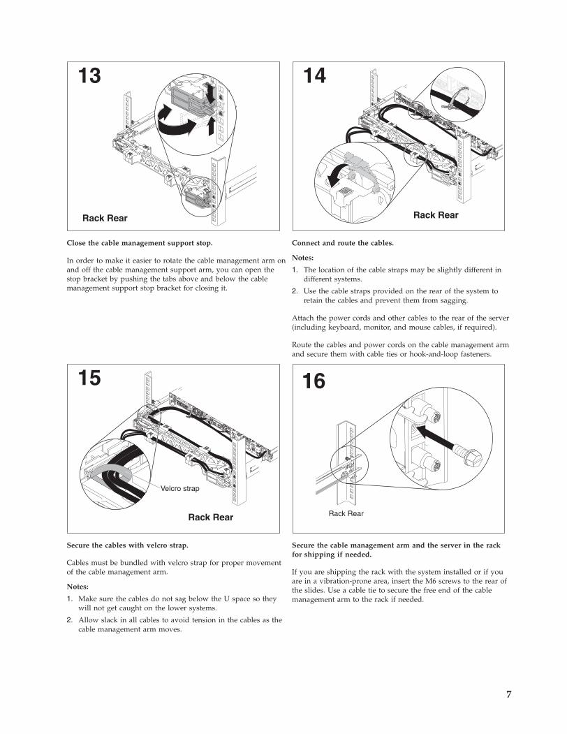
Close the cable management support stop.
In order to make it easier to rotate the cable management arm onand off the cable management support arm, you can open thestop bracket by pushing the tabs above and below the cablemanagement support stop bracket for closing it.
Connect and route the cables.
Notes:
1. The location of the cable straps may be slightly different indifferent systems.
2. Use the cable straps provided on the rear of the system toretain the cables and prevent them from sagging.
Attach the power cords and other cables to the rear of the server(including keyboard, monitor, and mouse cables, if required).
Route the cables and power cords on the cable management armand secure them with cable ties or hook-and-loop fasteners.
Rack Rear
15
Velcro strap
16
Rack Rear
1
Secure the cables with velcro strap.
Cables must be bundled with velcro strap for proper movementof the cable management arm.
Notes:
1. Make sure the cables do not sag below the U space so theywill not get caught on the lower systems.
2. Allow slack in all cables to avoid tension in the cables as thecable management arm moves.
Secure the cable management arm and the server in the rackfor shipping if needed.
If you are shipping the rack with the system installed or if youare in a vibration-prone area, insert the M6 screws to the rear ofthe slides. Use a cable tie to secure the free end of the cablemanagement arm to the rack if needed.
7
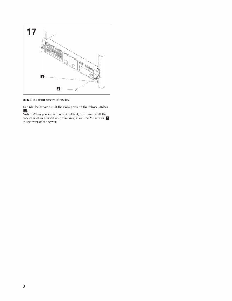
17
Install the front screws if needed.
To slide the server out of the rack, press on the release latches�1�.Note: When you move the rack cabinet, or if you install therack cabinet in a vibration-prone area, insert the M6 screws �2�in the front of the server.
8
Removing the server from the rack
1
Lift point
Lift point
2
3
2
2
2
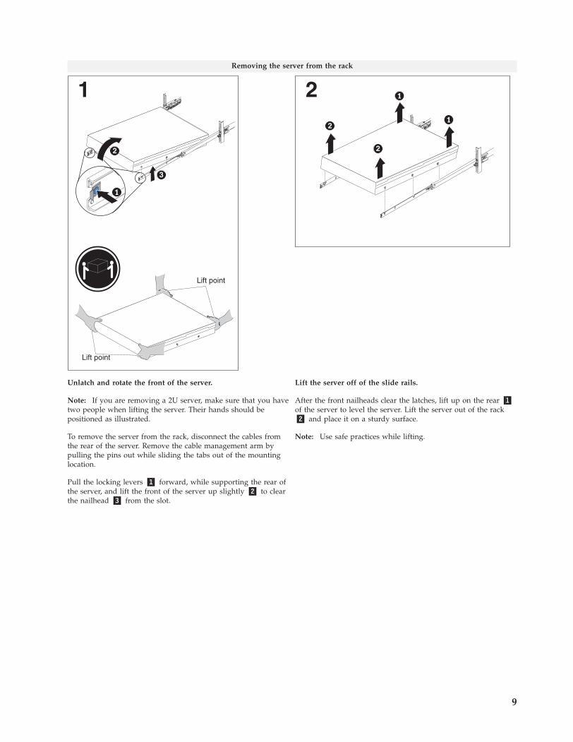
Unlatch and rotate the front of the server.
Note: If you are removing a 2U server, make sure that you havetwo people when lifting the server. Their hands should bepositioned as illustrated.
To remove the server from the rack, disconnect the cables fromthe rear of the server. Remove the cable management arm bypulling the pins out while sliding the tabs out of the mountinglocation.
Pull the locking levers �1� forward, while supporting the rear ofthe server, and lift the front of the server up slightly �2� to clearthe nailhead �3� from the slot.
Lift the server off of the slide rails.
After the front nailheads clear the latches, lift up on the rear �1�of the server to level the server. Lift the server out of the rack�2� and place it on a sturdy surface.
Note: Use safe practices while lifting.
9
3
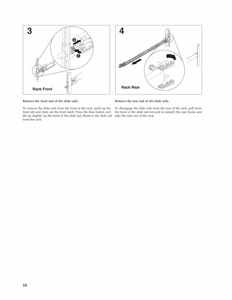
Rack Front
2
Remove the front end of the slide rails.
To remove the slide rails from the front of the rack, push up thefront tab and slide out the front latch. Press the blue button andlift up slightly on the front of the slide rail. Remove the slide railfrom the rack.
4
Rack Rear
Remove the rear end of the slide rails.
To disengage the slide rails from the rear of the rack, pull fromthe front of the slide rail forward to unlatch the rear hooks andtake the rails out of the rack.
10
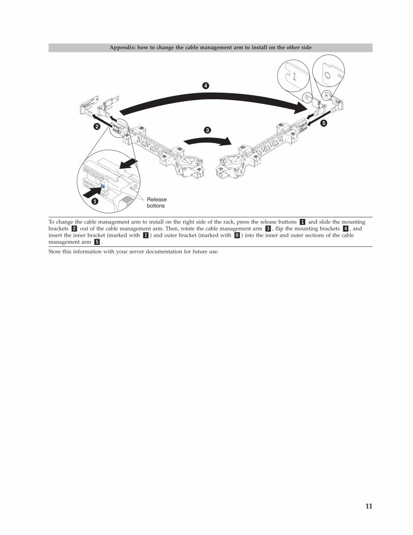
Appendix: how to change the cable management arm to install on the other side
Releasebottons
To change the cable management arm to install on the right side of the rack, press the release buttons �1� and slide the mountingbrackets �2� out of the cable management arm. Then, rotate the cable management arm �3�, flip the mounting brackets �4�, andinsert the inner bracket (marked with �I�) and outer bracket (marked with �O�) into the inner and outer sections of the cablemanagement arm �5�.
Store this information with your server documentation for future use.
11
First Edition (March 2012)
Printed in the U.S.A.
IBM is a trademark of the IBM Corporation in the United States, other countries, or both.
© Copyright IBM Corporation 2012.US Government Users Restricted Rights – Use, duplication or disclosure restricted by GSA ADP Schedule Contractwith IBM Corp.
(1P) P/N: 90Y5656