Embed Size (px)
Citation preview
Taking the heatCould thermal imaging be the death of the temperature probe?
Driver-friendly clutchTactile take-up technology
Aero hints and tipsWays to avoid drag
Ecotec engine1000bhp off the shelf
T h e I n t e r n a t i o n a l J o u r n a l™
TECHNOLOGY FOR MOTORSPORT
FUEL CELLS THINK TANKA look at what fuel containment technology can contribute
F1-POWERED HILLCLIMBERNew Martin Ogilvie-designed Predator breaks cover
November 2005 · Vol 15 No 11 www.racecar-engineering.com UK £4.50 · USA $8.95
9 770961 109050
1 1
3November 2005 Racecar Engineeringwww.racecar-engineering.com 3www.racecar-engineering.com
NO
VE
MB
ER
200
5
32
48
38
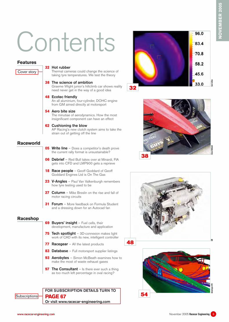
32 Hot rubberThermal cameras could change the science of taking tyre temperatures. We test the theory
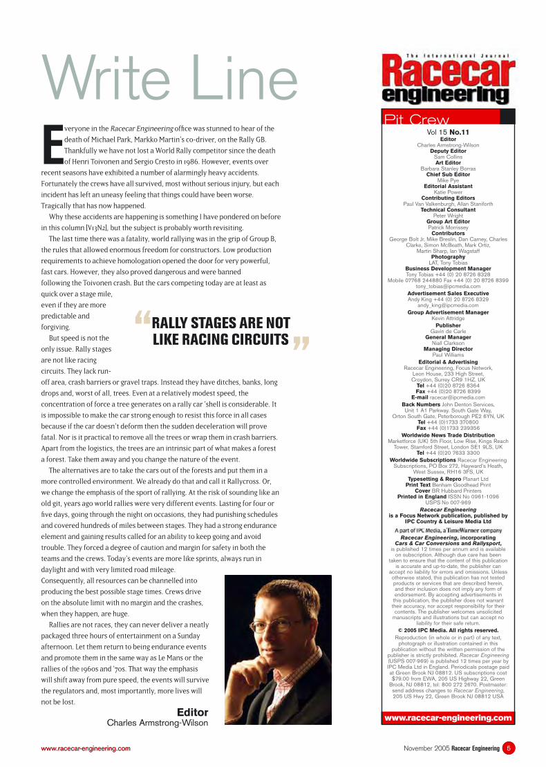
38 The science of ambitionGraeme Wight junior’s hillclimb car shows reality need never get in the way of a good idea
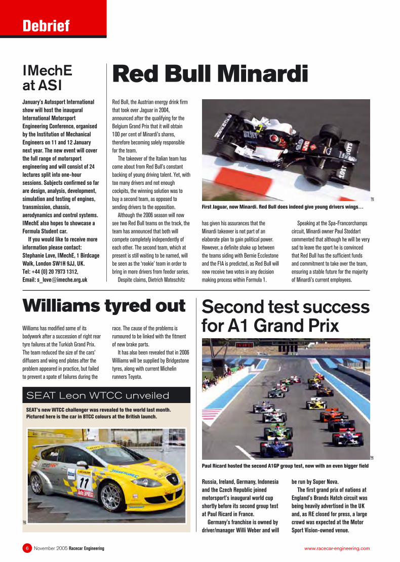
48 Ecotec friendlyAn all aluminium, four-cylinder, DOHC engine from GM aimed directly at motorsport
54 Aero bite size The minutiae of aerodynamics. How the most insignificant component can have an effect
62 Cushioning the blowAP Racing’s new clutch system aims to take the strain out of getting off the line
05 Write line – Does a competitor’s death prove the current rally format is unsustainable?
06 Debrief – Red Bull takes over at Minardi, FIA gets into CFD and LMP900 gets a reprieve
18 Race people – Geoff Goddard of Geoff Goddard Engines Ltd is On The Gas
23 V-Angles – Paul Van Valkenburgh remembers how tyre testing used to be
27 Column – Mike Breslin on the rise and fall of motor racing circuits
31 Forum – More feedback on Formula Student and a dressing down for an Autocad fan
69 Buyers’ insight – Fuel cells, their development, manufacture and application
75 Tech spotlight – 3D-connexion makes light work of CAD with its new, intelligent controller
77 Racegear – All the latest products
83 Database – Full motorsport supplier listings
93 Aerobytes – Simon McBeath examines how to make the most of waste exhaust gases
97 The Consultant – Is there ever such a thing as too much left percentage in oval racing?
Features
ContentsCover story
Raceworld
Raceshop
SubscriptionsFOR SUBSCRIPTION DETAILS TURN TO
PAGE 67Or visit www.racecar-engineering.com
Sam
Col
lins
Sim
on M
cBea
thGM
Adva
ntag
ee C
FD
54
5www.racecar-engineering.com 5November 2005 Racecar Engineeringwww.racecar-engineering.com
Pit Crew
www.racecar-engineering.com
EditorCharles Armstrong-Wilson
Deputy Editor Sam CollinsArt Editor
Barbara Stanley BorrasChief Sub Editor
Mike PyeEditorial Assistant
Katie PowerContributing Editors
Paul Van Valkenburgh, Allan StaniforthTechnical Consultant
Peter WrightGroup Art Editor Patrick Morrissey
ContributorsGeorge Bolt Jr, Mike Breslin, Dan Carney, Charles
Clarke, Simon McBeath, Mark Ortiz, Martin Sharp, Ian Wagstaff
PhotographyLAT, Tony Tobias
Business Development Manager Tony Tobias +44 (0) 20 8726 8328
Mobile 07768 244880 Fax +44 (0) 20 8726 [email protected]
Advertisement Sales ExecutiveAndy King +44 (0) 20 8726 8329
[email protected] Advertisement Manager
Kevin AttridgePublisher
Gavin de CarleGeneral Manager
Niall ClarksonManaging Director
Paul WilliamsEditorial & Advertising
Racecar Engineering, Focus Network,Leon House, 233 High Street, Croydon, Surrey CR9 1HZ, UK
Tel +44 (0)20 8726 8364Fax +44 (0)20 8726 8399
E-mail [email protected] Numbers John Denton Services, Unit 1 A1 Parkway. South Gate Way,
Orton South Gate, Peterborough PE2 6YN, UKTel +44 (0)1733 370800 Fax +44 (0)1733 239356
Worldwide News Trade Distribution Marketforce (UK) 5th Floor, Low Rise, Kings Reach
Tower, Stamford Street, London SE1 9LS, UKTel +44 (0)20 7633 3300
Worldwide Subscriptions Racecar Engineering Subscriptions, PO Box 272, Hayward’s Heath,
West Sussex, RH16 3FS, UKTypesetting & Repro Planart Ltd
Print Text Benham Goodhead Print Cover BR Hubbard Printers
Printed in England ISSN No 0961-1096 USPS No 007-969
Racecar Engineeringis a Focus Network publication, published by
IPC Country & Leisure Media Ltd
Racecar Engineering, incorporating Cars & Car Conversions and Rallysport,
is published 12 times per annum and is available on subscription. Although due care has been
taken to ensure that the content of this publication is accurate and up-to-date, the publisher can
accept no liability for errors and omissions. Unless otherwise stated, this publication has not tested products or services that are described herein, and their inclusion does not imply any form of endorsement. By accepting advertisements in
this publication, the publisher does not warrant their accuracy, nor accept responsibility for their contents. The publisher welcomes unsolicited
manuscripts and illustrations but can accept no liability for their safe return.
© 2005 IPC Media. All rights reserved.Reproduction (in whole or in part) of any text,
photograph or illustration contained in this publication without the written permission of the
publisher is strictly prohibited. Racecar Engineering (USPS 007-969) is published 12 times per year by IPC Media Ltd in England. Periodicals postage paid at Green Brook NJ 08812. US subscriptions cost $79.00 from EWA, 205 US Highway 22, Green
Brook, NJ 08812, tel: 800 272 2670. Postmaster: send address changes to Racecar Engineering,205 US Hwy 22, Green Brook NJ 08812 USA
Vol 15 No.11
Everyone in the Racecar Engineering offi ce was stunned to hear of the
death of Michael Park, Markko Martin’s co-driver, on the Rally GB.
Thankfully we have not lost a World Rally competitor since the death
of Henri Toivonen and Sergio Cresto in 1986. However, events over
recent seasons have exhibited a number of alarmingly heavy accidents.
Fortunately the crews have all survived, most without serious injury, but each
incident has left an uneasy feeling that things could have been worse.
Tragically that has now happened.
Why these accidents are happening is something I have pondered on before
in this column [V13N2], but the subject is probably worth revisiting.
The last time there was a fatality, world rallying was in the grip of Group B,
the rules that allowed enormous freedom for constructors. Low production
requirements to achieve homologation opened the door for very powerful,
fast cars. However, they also proved dangerous and were banned
following the Toivonen crash. But the cars competing today are at least as
quick over a stage mile,
even if they are more
predictable and
forgiving.
But speed is not the
only issue. Rally stages
are not like racing
circuits. They lack run-
off area, crash barriers or gravel traps. Instead they have ditches, banks, long
drops and, worst of all, trees. Even at a relatively modest speed, the
concentration of force a tree generates on a rally car ’shell is considerable. It
is impossible to make the car strong enough to resist this force in all cases
because if the car doesn’t deform then the sudden deceleration will prove
fatal. Nor is it practical to remove all the trees or wrap them in crash barriers.
Apart from the logistics, the trees are an intrinsic part of what makes a forest
a forest. Take them away and you change the nature of the event.
The alternatives are to take the cars out of the forests and put them in a
more controlled environment. We already do that and call it Rallycross. Or,
we change the emphasis of the sport of rallying. At the risk of sounding like an
old git, years ago world rallies were very different events. Lasting for four or
fi ve days, going through the night on occasions, they had punishing schedules
and covered hundreds of miles between stages. They had a strong endurance
element and gaining results called for an ability to keep going and avoid
trouble. They forced a degree of caution and margin for safety in both the
teams and the crews. Today’s events are more like sprints, always run in
daylight and with very limited road mileage.
Consequently, all resources can be channelled into
producing the best possible stage times. Crews drive
on the absolute limit with no margin and the crashes,
when they happen, are huge.
Rallies are not races, they can never deliver a neatly
packaged three hours of entertainment on a Sunday
afternoon. Let them return to being endurance events
and promote them in the same way as Le Mans or the
rallies of the 1960s and ’70s. That way the emphasis
will shift away from pure speed, the events will survive
the regulators and, most importantly, more lives will
not be lost.
EditorCharles Armstrong-Wilson
Write Line
“RALLY STAGES ARE NOTLIKE RACING CIRCUITS
”
Debrief
November 2005 Racecar Engineering6 www.racecar-engineering.com
Red Bull, the Austrian energy drink fi rm
that took over Jaguar in 2004,
announced after the qualifying for the
Belgium Grand Prix that it will obtain
100 per cent of Minardi’s shares,
therefore becoming solely responsible
for the team.
The takeover of the Italian team has
come about from Red Bull’s constant
backing of young driving talent. Yet, with
too many drivers and not enough
cockpits, the winning solution was to
buy a second team, as opposed to
sending drivers to the opposition.
Although the 2006 season will now
see two Red Bull teams on the track, the
team has announced that both will
compete completely independently of
each other. The second team, which at
present is still waiting to be named, will
be seen as the ‘rookie’ team in order to
bring in more drivers from feeder series.
Despite claims, Dietrich Mateschitz
Red Bull Minardi
has given his assurances that the
Minardi takeover is not part of an
elaborate plan to gain political power.
However, a defi nite shake up between
the teams siding with Bernie Ecclestone
and the FIA is predicted, as Red Bull will
now receive two votes in any decision
making process within Formula 1.
Speaking at the Spa-Francorchamps
circuit, Minardi owner Paul Stoddart
commented that although he will be very
sad to leave the sport he is convinced
that Red Bull has the suffi cient funds
and commitment to take over the team,
ensuring a stable future for the majority
of Minardi’s current employees.
SEAT’s new WTCC challenger was revealed to the world last month.
Pictured here is the car in BTCC colours at the British launch.
SEAT Leon WTCC unveiled
First Jaguar, now Minardi. Red Bull does indeed give young drivers wings…
Russia, Ireland, Germany, Indonesia
and the Czech Republic joined
motorsport’s inaugural world cup
shortly before its second group test
at Paul Ricard in France.
Germany’s franchise is owned by
driver/manager Willi Weber and will
Williams has modifi ed some of its
bodywork after a succession of right rear
tyre failures at the Turkish Grand Prix.
The team reduced the size of the cars’
diffusers and wing end plates after the
problem appeared in practice, but failed
to prevent a spate of failures during the
Williams tyred out
January’s Autosport International
show will host the inaugural
International Motorsport
Engineering Conference, organised
by the Institution of Mechanical
Engineers on 11 and 12 January
next year. The new event will cover
the full range of motorsport
engineering and will consist of 24
lectures split into one-hour
sessions. Subjects confi rmed so far
are design, analysis, development,
simulation and testing of engines,
transmission, chassis,
aerodynamics and control systems.
IMechE also hopes to showcase a
Formula Student car.
If you would like to receive more
information please contact:
Stephanie Love, IMechE, 1 Birdcage
Walk, London SW1H 9JJ, UK.
Tel: +44 (0) 20 7973 1312,
Email: [email protected]
IMechE at ASI
Second test success for A1 Grand Prix
Paul Ricard hosted the second A1GP group test, now with an even bigger fi eld
LAT
LAT
be run by Super Nova.
The fi rst grand prix of nations at
England’s Brands Hatch circuit was
being heavily advertised in the UK
and, as RE closed for press, a large
crowd was expected at the Motor
Sport Vision-owned venue.
race. The cause of the problems is
rumoured to be linked with the fi tment
of new brake parts.
It has also been revealed that in 2006
Williams will be supplied by Bridgestone
tyres, along with current Michelin
runners Toyota.
LAT
Debrief
7November 2005 Racecar Engineeringwww.racecar-engineering.com
GM has confi rmed its withdrawal from
the Indy Racing League. Currently
Cosworth’s IRL powerplant is badged
Chevrolet and, if the Cosworth units
were withdrawn from the series, it would
leave teams with only one engine choice
as Toyota has already announced its
GM confi rms IRL withdrawal
The British attempt on the steam car
world record is gathering momentum as
the team unveiled its completed chassis
in September. Since last mentioned in
Racecar in 2000 (V10N6) many changes
have been made, including turning the
car’s steam turbine through 90 degrees
from transverse to longitudinal. The
turbine has been specially designed and
built for the job after a suitable off-the-
shelf unit couldn’t be found.
Chief engineer Glynne Bowsher and
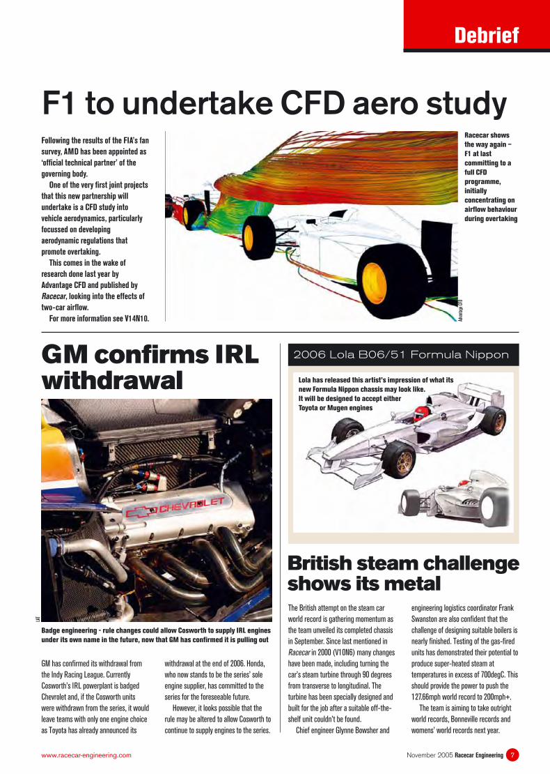
F1 to undertake CFD aero studyFollowing the results of the FIA’s fan
survey, AMD has been appointed as
‘offi cial technical partner’ of the
governing body.
One of the very fi rst joint projects
that this new partnership will
undertake is a CFD study into
vehicle aerodynamics, particularly
focussed on developing
aerodynamic regulations that
promote overtaking.
This comes in the wake of
research done last year by
Advantage CFD and published by
Racecar, looking into the effects of
two-car airfl ow.
For more information see V14N10. Adva
ntag
e CF
D
Racecar shows
the way again –
F1 at last
committing to a
full CFD
programme,
initially
concentrating on
airfl ow behaviour
during overtaking
withdrawal at the end of 2006. Honda,
who now stands to be the series’ sole
engine supplier, has committed to the
series for the foreseeable future.
However, it looks possible that the
rule may be altered to allow Cosworth to
continue to supply engines to the series.
Badge engineering - rule changes could allow Cosworth to supply IRL engines
under its own name in the future, now that GM has confi rmed it is pulling out
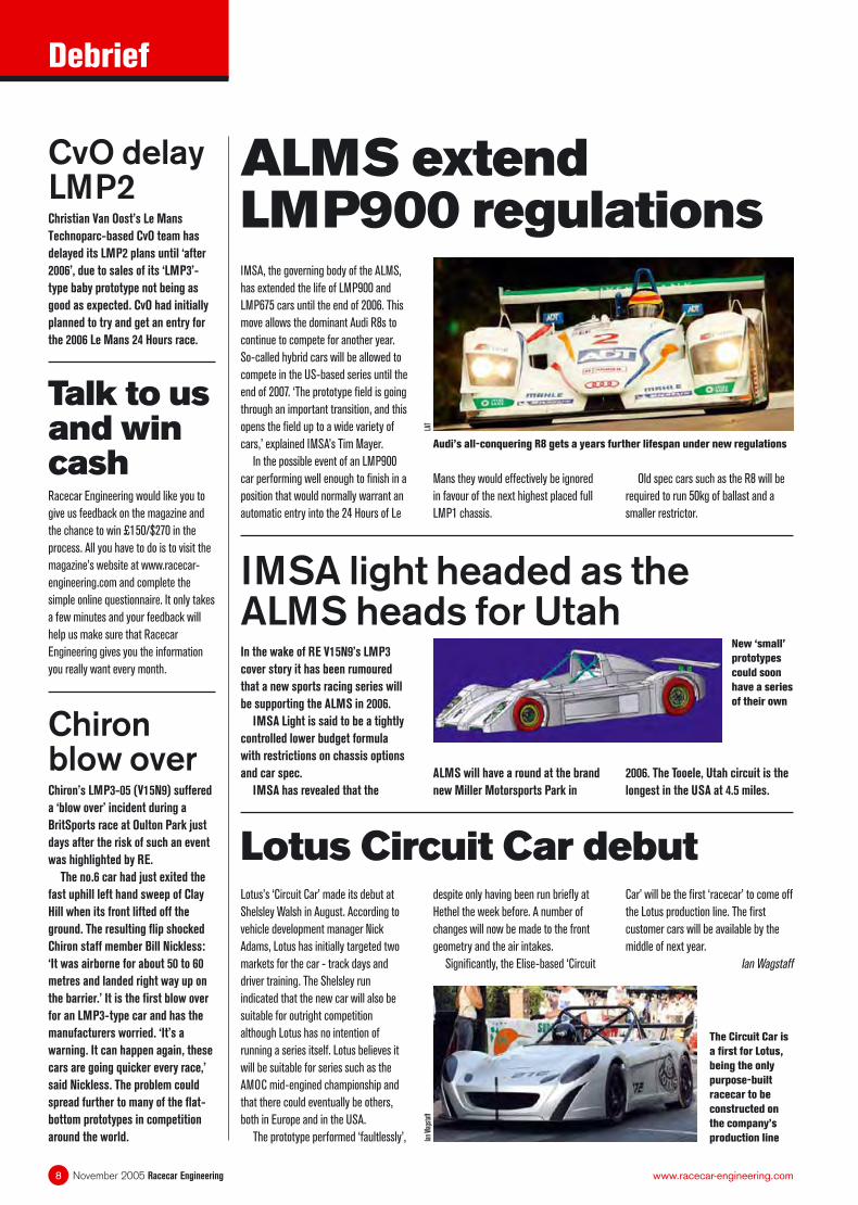
2006 Lola B06/51 Formula Nippon
British steam challenge shows its metal
LAT
engineering logistics coordinator Frank
Swanston are also confi dent that the
challenge of designing suitable boilers is
nearly fi nished. Testing of the gas-fi red
units has demonstrated their potential to
produce super-heated steam at
temperatures in excess of 700degC. This
should provide the power to push the
127.66mph world record to 200mph+.
The team is aiming to take outright
world records, Bonneville records and
womens’ world records next year.
Lola has released this artist’s impression of what its
new Formula Nippon chassis may look like.
It will be designed to accept either
Toyota or Mugen engines
IMSA, the governing body of the ALMS,
has extended the life of LMP900 and
LMP675 cars until the end of 2006. This
move allows the dominant Audi R8s to
continue to compete for another year.
So-called hybrid cars will be allowed to
compete in the US-based series until the
end of 2007. ‘The prototype fi eld is going
through an important transition, and this
opens the fi eld up to a wide variety of
cars,’ explained IMSA’s Tim Mayer.
In the possible event of an LMP900
car performing well enough to fi nish in a
position that would normally warrant an
automatic entry into the 24 Hours of Le
LAT
ALMS extend LMP900 regulations
Mans they would effectively be ignored
in favour of the next highest placed full
LMP1 chassis.
Lotus Circuit Car debutLotus’s ‘Circuit Car’ made its debut at
Shelsley Walsh in August. According to
vehicle development manager Nick
Adams, Lotus has initially targeted two
markets for the car - track days and
driver training. The Shelsley run
indicated that the new car will also be
suitable for outright competition
although Lotus has no intention of
running a series itself. Lotus believes it
will be suitable for series such as the
AMOC mid-engined championship and
that there could eventually be others,
both in Europe and in the USA.
The prototype performed ‘faultlessly’,
despite only having been run briefl y at
Hethel the week before. A number of
changes will now be made to the front
geometry and the air intakes.
Signifi cantly, the Elise-based ‘Circuit
Debrief
November 2005 Racecar Engineering8 www.racecar-engineering.com
Old spec cars such as the R8 will be
required to run 50kg of ballast and a
smaller restrictor.
Chiron’s LMP3-05 (V15N9) suffered
a ‘blow over’ incident during a
BritSports race at Oulton Park just
days after the risk of such an event
was highlighted by RE.
The no.6 car had just exited the
fast uphill left hand sweep of Clay
Hill when its front lifted off the
ground. The resulting fl ip shocked
Chiron staff member Bill Nickless:
‘It was airborne for about 50 to 60
metres and landed right way up on
the barrier.’ It is the fi rst blow over
for an LMP3-type car and has the
manufacturers worried. ‘It’s a
warning. It can happen again, these
cars are going quicker every race,’
said Nickless. The problem could
spread further to many of the fl at-
bottom prototypes in competition
around the world.
Audi’s all-conquering R8 gets a years further lifespan under new regulations
The Circuit Car is
a fi rst for Lotus,
being the only
purpose-built
racecar to be
constructed on
the company’s
production line Ian
Wag
staf
f
Racecar Engineering would like you to
give us feedback on the magazine and
the chance to win £150/$270 in the
process. All you have to do is to visit the
magazine’s website at www.racecar-
engineering.com and complete the
simple online questionnaire. It only takes
a few minutes and your feedback will
help us make sure that Racecar
Engineering gives you the information
you really want every month.
Car’ will be the fi rst ‘racecar’ to come off
the Lotus production line. The fi rst
customer cars will be available by the
middle of next year.
Ian Wagstaff
Talk to us and win cash
IMSA light headed as the ALMS heads for UtahIn the wake of RE V15N9’s LMP3
cover story it has been rumoured
that a new sports racing series will
be supporting the ALMS in 2006.
IMSA Light is said to be a tightly
controlled lower budget formula
with restrictions on chassis options
and car spec.
IMSA has revealed that the
2006. The Tooele, Utah circuit is the
longest in the USA at 4.5 miles.
ALMS will have a round at the brand
new Miller Motorsports Park in
Christian Van Oost’s Le Mans
Technoparc-based CvO team has
delayed its LMP2 plans until ‘after
2006’, due to sales of its ‘LMP3’-
type baby prototype not being as
good as expected. CvO had initially
planned to try and get an entry for
the 2006 Le Mans 24 Hours race.
CvO delay LMP2
New ‘small’
prototypes
could soon
have a series
of their own
Chiron blow over
New FSAE announcedFormula SAE has a new event in 2006.
FSAE West is to be held at the California
Speedway in June next year. The event
will sit alongside the traditional Formula
SAE event which will run from 17–21
May 2006. FSAE West is scheduled to
take place between 14-17 June.
‘Formula SAE West is being opened to
meet the growing demand of university
teams to compete in North America. For
the past three years all 140 slots at
Formula SAE were sold out,’ explained
Steve Daum, the SAE’s collegiate
manager. ‘Registration for FSAE 2005
fi lled up in just 73 minutes and we know
of over 30 teams that couldn’t get a slot.
With a second competition there should
be space available for every team that
wants to compete,’ he continued.
Recruiting of event captains, judges,
technical inspectors (scrutineers) and
other volunteers necessary to the
successful running of the event will start
soon. Anyone based in the Los Angeles
area with knowledge of motorsport
engineering and design who might be
interested in becoming involved are
asked to step forward and volunteer.
MoTeC and Rouelle go on tourThe European leg of the ever-popular
Racecar Dynamics and Data Acquisition
Seminars, presented by Claude Rouelle,
begins this November, with courses in
Italy, France, Germany and the UK. The
fi nal ’06 seminar will be held in Orlando,
USA after the December PRI show.
November dates are: 5-7 USA; 11-13
Italy; 15-17 France; 19-21 Germany;
23-25 and 26-28 UK (the second UK
date being a Formula Student special).
‘We picked California Speedway
because it’s a great site where we can
lay out challenging and exciting courses,
and it is also a site that provides
excellent pits and support facilities.
Locating the second competition in
California will make Formula SAE more
accessible to, and lower the travel costs
of, universities on the West coast and
around the Pacifi c Rim.’
Debrief
11November 2005 Racecar Engineeringwww.racecar-engineering.com
LAT
NEWS IN BRIEF Williams has confi rmed that it will be using
Cosworth V8 engines throughout the 2006
Formula 1 season.
Houston will return to the Champ Car
calendar in 2006, bringing the series to 15
rounds in total.
SEAT’s BTCC Toledo Cupra Rs have been
given a 15kg weight reduction to move the
super 2000 spec base weight to 1085kg. The
move comes as part of the attempts to
equalise the performance of British and World
spec touring cars.
Panoz Esperante GTLM customer cars will
be competing in LMES next year, most likely
with Team LNT. Courage Competition has
been involved with the cars European sales.
Historic Russian marque Russo-Baltique
looks set to return to the track, with A-Level
Engineering boss Vladimir Raikhlin planning
to revive the company.
Circuit de Catalunya is planning to increase
its seating capacity by 8000 for the Spanish
Grand Prix next year.
Antonio Ferrari’s Euro International team
will take part in a number of Champ Car
races next season. The team has already
equipped for the campaign.
GP2 cars will have fully reworked aero next
year, along with slick tyres. Bridgestone is
likely to continue as the single tyre supplier.
California
Speedway is to
host the new
event in 2006
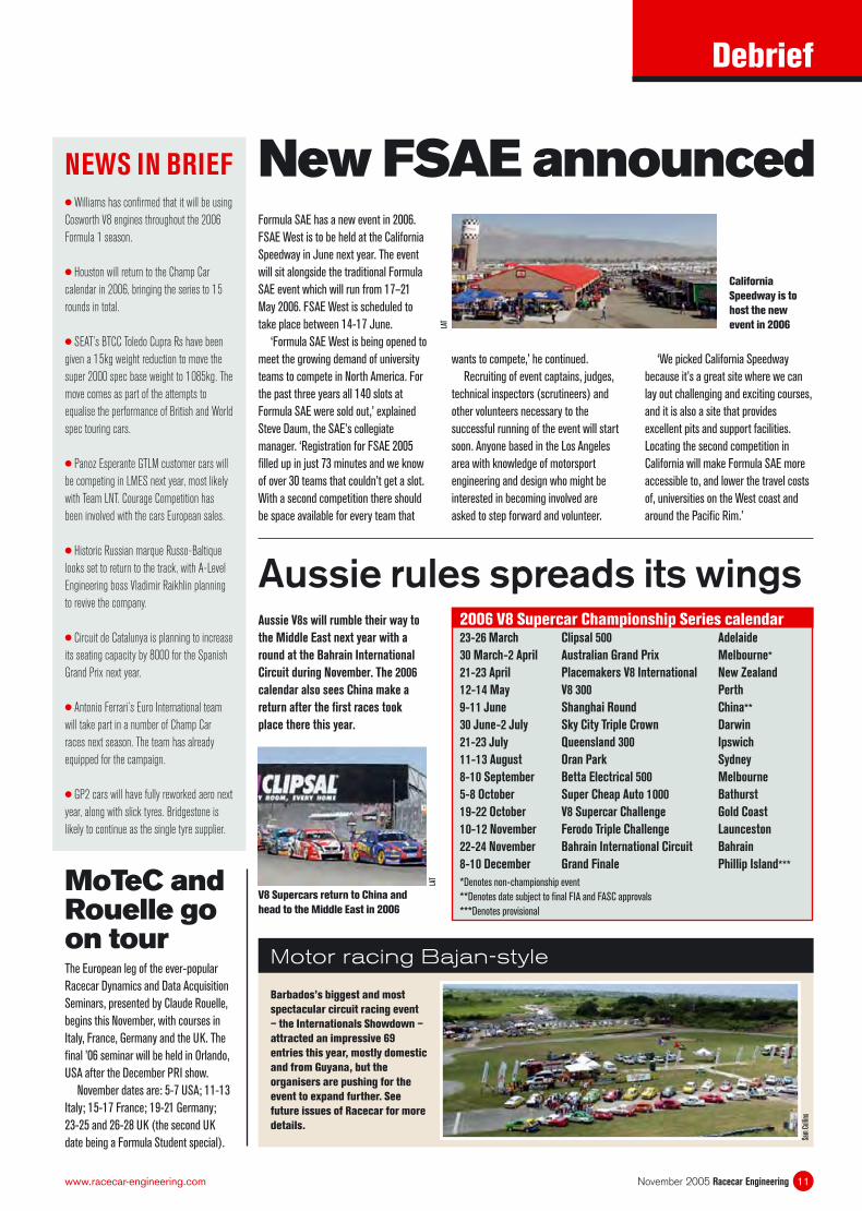
Aussie rules spreads its wings2006 V8 Supercar Championship Series calendar23-26 March Clipsal 500 Adelaide
30 March-2 April Australian Grand Prix Melbourne*
21-23 April Placemakers V8 International New Zealand
12-14 May V8 300 Perth
9-11 June Shanghai Round China**
30 June-2 July Sky City Triple Crown Darwin
21-23 July Queensland 300 Ipswich
11-13 August Oran Park Sydney
8-10 September Betta Electrical 500 Melbourne
5-8 October Super Cheap Auto 1000 Bathurst
19-22 October V8 Supercar Challenge Gold Coast
10-12 November Ferodo Triple Challenge Launceston
22-24 November Bahrain International Circuit Bahrain
8-10 December Grand Finale Phillip Island***
*Denotes non-championship event
**Denotes date subject to fi nal FIA and FASC approvals
***Denotes provisional
Aussie V8s will rumble their way to
the Middle East next year with a
round at the Bahrain International
Circuit during November. The 2006
calendar also sees China make a
return after the fi rst races took
place there this year.
V8 Supercars return to China and
head to the Middle East in 2006
LAT
Barbados’s biggest and most
spectacular circuit racing event
– the Internationals Showdown –
attracted an impressive 69
entries this year, mostly domestic
and from Guyana, but the
organisers are pushing for the
event to expand further. See
future issues of Racecar for more
details.
Motor racing Bajan-style
Sam
Col
lins
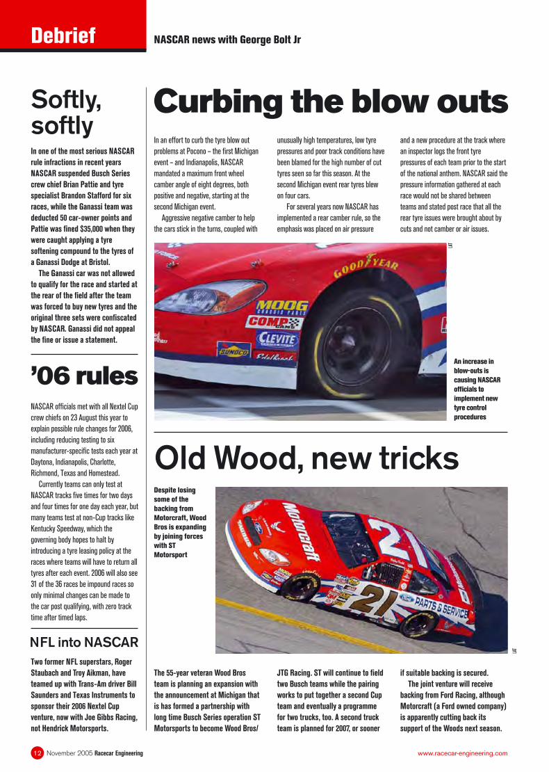
In an effort to curb the tyre blow out
problems at Pocono – the fi rst Michigan
event – and Indianapolis, NASCAR
mandated a maximum front wheel
camber angle of eight degrees, both
positive and negative, starting at the
second Michigan event.
Aggressive negative camber to help
the cars stick in the turns, coupled with
Despite losing
some of the
backing from
Motorcraft, Wood
Bros is expanding
by joining forces
with ST
Motorsport
An increase in
blow-outs is
causing NASCAR
offi cials to
implement new
tyre control
procedures
Curbing the blow outsunusually high temperatures, low tyre
pressures and poor track conditions have
been blamed for the high number of cut
tyres seen so far this season. At the
second Michigan event rear tyres blew
on four cars.
For several years now NASCAR has
implemented a rear camber rule, so the
emphasis was placed on air pressure
The 55-year veteran Wood Bros
team is planning an expansion with
the announcement at Michigan that
is has formed a partnership with
long time Busch Series operation ST
Motorsports to become Wood Bros/
Old Wood, new tricks
’06 rulesNASCAR offi cials met with all Nextel Cup
crew chiefs on 23 August this year to
explain possible rule changes for 2006,
including reducing testing to six
manufacturer-specifi c tests each year at
Daytona, Indianapolis, Charlotte,
Richmond, Texas and Homestead.
Currently teams can only test at
NASCAR tracks fi ve times for two days
and four times for one day each year, but
many teams test at non-Cup tracks like
Kentucky Speedway, which the
governing body hopes to halt by
introducing a tyre leasing policy at the
races where teams will have to return all
tyres after each event. 2006 will also see
31 of the 36 races be impound races so
only minimal changes can be made to
the car post qualifying, with zero track
time after timed laps.
JTG Racing. ST will continue to fi eld
two Busch teams while the pairing
works to put together a second Cup
team and eventually a programme
for two trucks, too. A second truck
team is planned for 2007, or sooner
Debrief
November 2005 Racecar Engineering12 www.racecar-engineering.com
and a new procedure at the track where
an inspector logs the front tyre
pressures of each team prior to the start
of the national anthem. NASCAR said the
pressure information gathered at each
race would not be shared between
teams and stated post race that all the
rear tyre issues were brought about by
cuts and not camber or air issues.
NASCAR news with George Bolt Jr
In one of the most serious NASCAR
rule infractions in recent years
NASCAR suspended Busch Series
crew chief Brian Pattie and tyre
specialist Brandon Stafford for six
races, while the Ganassi team was
deducted 50 car-owner points and
Pattie was fi ned $35,000 when they
were caught applying a tyre
softening compound to the tyres of
a Ganassi Dodge at Bristol.
The Ganassi car was not allowed
to qualify for the race and started at
the rear of the fi eld after the team
was forced to buy new tyres and the
original three sets were confi scated
by NASCAR. Ganassi did not appeal
the fi ne or issue a statement.
Softly, softly
if suitable backing is secured.
The joint venture will receive
backing from Ford Racing, although
Motorcraft (a Ford owned company)
is apparently cutting back its
support of the Woods next season.
LAT
Two former NFL superstars, Roger
Staubach and Troy Aikman, have
teamed up with Trans-Am driver Bill
Saunders and Texas Instruments to
sponsor their 2006 Nextel Cup
venture, now with Joe Gibbs Racing,
not Hendrick Motorsports.
LAT
NFL into NASCAR
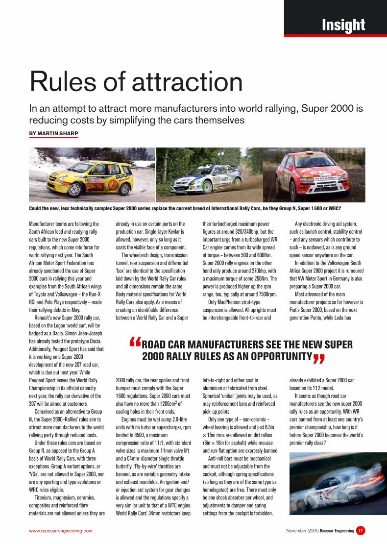
The true cause of the Peugeot 307
WRC’s failure to inspire confi dence in its
works drivers continues to evade its
engineers, although progress has been
made through positive developments in
the way its shock absorbers operate.
One car was equipped with hybrid
Peugeot/Öhlins dampers for Rally
Finland. The driver found the now more
conventional shim pack-restricted
Swedish damper inserts to be more
predictable in their operation than the
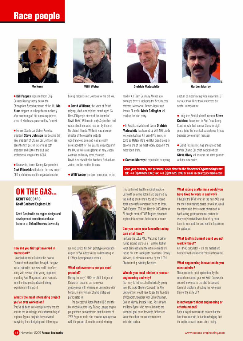
Choice of either the fi ve- or six-speed gearbox will be down to driver discretion
Peugeot still troubled by damper demands
Peugeot units. It was also noted that the
opportunity for these to be adjusted for
rate through the simple expedient of ‘a
few clicks’, rather than the more lengthy
and intensive dismantling procedure
required by the valve-equipped in-house
shocks, offered greater fl exibility.
For Rally Deutschland, continued
development was deemed to have
reduced friction in the Peugeot dampers
and both works Peugeot drivers were
returned to these.
A revised fi ve-speed gearbox was
used in two of the three offi cial
works Skoda Fabia WRCs on Rally
Deutschland. Designed and
manufactured by Xtrac in the UK,
these gearboxes will be available as
an option to the originally
homologated, Xtrac designed and
built, six-speed unit until the end of
this year.
The offi cial Skoda team will know
whether it can continue world
championship rallying into 2006
after a board meeting being held in
mid-September.
Skoda slides revised fi veOn yer ’bikeThe UK’s governing motorsport body, the
Motor Sports Association, has ‘clarifi ed’
its ruling on the use of motorcycle-
engined cars in rallies.
It deems that this comparatively
reliable and economical method of
providing the necessary power for
competition machines is now
unacceptable in rallying.
However, it has also been decided
that competition car log books for
vehicles already existing with this
confi guration will not be withdrawn,
although any new applications to
register motorbike-engined rally cars
will be rejected.
Debrief
November 2005 Racecar Engineering14 www.racecar-engineering.com
Like Peugeot, the works Mitsubishi
rally team has also invested heavily in an
in-house damper development facility
and has designed its own valve-type
shock absorbers which have been run on
the works Lancer WRCs since the
beginning of the 2005 WRC season. It is
said that the Japanese team has also
investigated Öhlins dampers as an
alternative. Öhlins units were used on
Mitsubishi works rally cars before the
team developed its own-brand dampers.
Rally news with Martin Sharp
LAT
Further
development by
team Peugeot
saw the cars
returned to in-
house dampers
for Rally
Deutschland
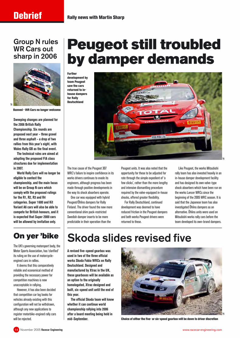
Sweeping changes are planned for
the 2006 British Rally
Championship. Six rounds are
proposed next year – three gravel
and three asphalt – a drop of two
rallies from this year’s eight, with
Wales Rally GB as the fi nal event.
The technical rules are aimed at
adopting the proposed FIA class
structures due for implementation
in 2007.
World Rally Cars will no longer be
eligible to contest the
championship, and the main focus
will be on Group N cars which
comply with the proposed rulings
for the R1, R2, R3 and R4
categories. Super 1600 and Kit
Variant A6 cars will also be able to
compete for British honours, and it
is expected that Super 2000 cars
will be allowed by invitation only.
Group N rules WR Cars out sharp in 2006
Banned - WR Cars no longer welcome
LAT
LAT
Manufacturer teams are following the
South African lead and readying rally
cars built to the new Super 2000
regulations, which come into force for
world rallying next year. The South
African Motor Sport Federation has
already sanctioned the use of Super
2000 cars in rallying this year and
examples from the South African wings
of Toyota and Volkswagen – the Run-X
RSi and Polo Playa respectively – made
their rallying debuts in May.
Renault’s new Super 2000 rally car,
based on the Logan ‘world car’, will be
badged as a Dacia. Simon Jean-Joseph
has already tested the prototype Dacia.
Additionally, Peugeot Sport has said that
it is working on a Super 2000
development of the new 207 road car,
which is due out next year. While
Peugeot Sport leaves the World Rally
Championship in its offi cial capacity
next year, the rally car derivative of the
207 will be aimed at customers
Conceived as an alternative to Group
N, the Super 2000–Rallies’ rules aim to
attract more manufacturers to the world
rallying party through reduced costs.
Under these rules cars are based on
Group N, as opposed to the Group A
basis of World Rally Cars, with three
exceptions. Group A variant options, or
‘VOs’, are not allowed in Super 2000, nor
are any sporting and type evolutions or
WRC rules eligible.
Titanium, magnesium, ceramics,
composites and reinforced fi bre
materials are not allowed unless they are
already in use on certain parts on the
production car. Single-layer Kevlar is
allowed, however, only so long as it
coats the visible face of a component.
The wheelarch design, transmission
tunnel, rear suspension and differential
’box’ are identical to the specifi cation
laid down by the World Rally Car rules
and all dimensions remain the same.
Body material specifi cations for World
Rally Cars also apply. As a means of
creating an identifi able difference
between a World Rally Car and a Super
2000 rally car, the rear spoiler and front
bumper must comply with the Super
1600 regulations. Super 2000 cars must
also have no more than 1200cm2 of
cooling holes in their front ends.
Engines must be wet sump 2.0-litre
units with no turbo or supercharger, rpm
limited to 8500, a maximum
compression ratio of 11:1, with standard
valve sizes, a maximum 11mm valve lift
and a 64mm-diameter single throttle
butterfl y. ‘Fly-by-wire’ throttles are
banned, as are variable geometry intake
and exhaust manifolds. An ignition and/
or injection cut system for gear changes
is allowed and the regulations specify a
very similar unit to that of a WTC engine.
World Rally Cars’ 34mm restrictors keep
their turbocharged maximum power
fi gures at around 320/340bhp, but the
important urge from a turbocharged WR
Car engine comes from its wide spread
of torque – between 500 and 600Nm.
Super 2000 rally engines on the other
hand only produce around 270bhp, with
a maximum torque of some 250Nm. The
power is produced higher up the rpm
range, too, typically at around 7500rpm.
Only MacPherson strut-type
suspension is allowed. All uprights must
be interchangeable front-to-rear and
left-to-right and either cast in
aluminium or fabricated from steel.
Spherical ‘uniball’ joints may be used, as
may reinforcement bars and reinforced
pick-up points.
Only one type of – non-ceramic –
wheel bearing is allowed and just 6.5in
× 15in rims are allowed on dirt rallies
(8in × 18in for asphalt) while mousse
and run-fl at option are expressly banned.
Anti-roll bars must be mechanical
and must not be adjustable from the
cockpit, although spring specifi cations
(so long as they are of the same type as
homologated) are free. There must only
be one shock absorber per wheel, and
adjustments to damper and spring
settings from the cockpit is forbidden.
Any electronic driving aid system,
such as launch control, stability control
– and any sensors which contribute to
such – is outlawed, as is any ground
speed sensor anywhere on the car.
In addition to the Volkswagen South
Africa Super 2000 project it is rumoured
that VW Motor Sport in Germany is also
preparing a Super 2000 car.
Most advanced of the main
manufacturer projects so far however is
Fiat’s Super 2000, based on the next
generation Punto, while Lada has
already exhibited a Super 2000 car
based on its 112 model.
It seems as though road car
manufacturers see the new super 2000
rally rules as an opportunity. With WR
cars banned from at least one country’s
premier championship, how long is it
before Super 2000 becomes the world’s
premier rally class?
Insight
17November 2005 Racecar Engineeringwww.racecar-engineering.com
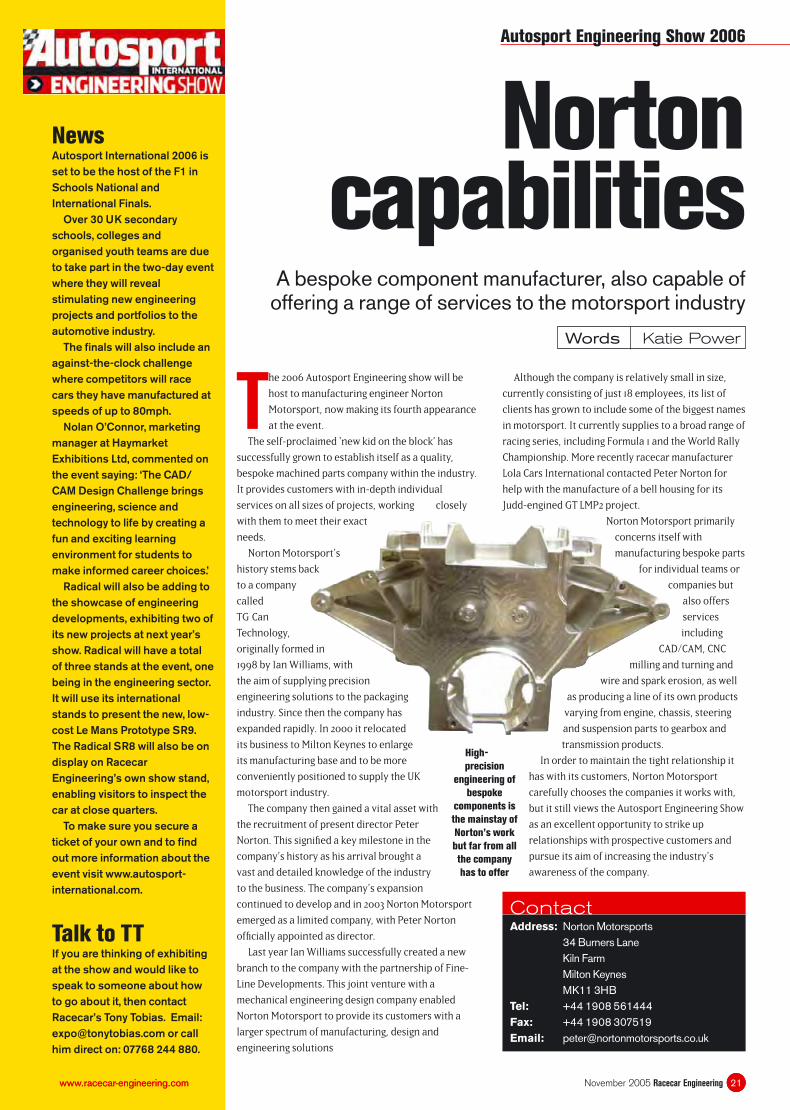
Rules of attractionIn an attempt to attract more manufacturers into world rallying, Super 2000 is reducing costs by simplifying the cars themselves BY MARTIN SHARP
Could the new, less technically complex Super 2000 series replace the current breed of International Rally Cars, be they Group N, Super 1600 or WRC?
“ROAD CAR MANUFACTURERS SEE THE NEW SUPER 2000 RALLY RULES AS AN OPPORTUNITY
”
Race people
November 2005 Racecar Engineering18 www.racecar-engineering.com
● Bill Pappas separated from Chip
Ganassi Racing shortly before the
Chicagoland Speedway round of the IRL. Mo
Nunn stepped in to help the team shortly
after auctioning off his team’s equipment,
some of which was purchased by Ganassi.
● Former Sports Car Club of America
president Steve Johnson has become the
new president of Champ Car. Johnson had
been the fi rst person to serve as both
president and CEO of the club and
professional wings of the SCCA.
● Meanwhile, former Champ Car president
Dick Eidswick will take on the new role of
CEO and chairman of the organisation after
having helped select Johnson for his old role.
● David Williams, the ‘voice of British
rallying’, died suddenly last month aged 43.
Over 300 people attended the funeral of
David ‘Deke’ Williams in early September, and
words about him were read out by three of
his closest friends. Williams was a founder
director of the essential website
worldrallynews.com and was also rally
correspondent for The Guardian newspaper in
the UK, as well as magazines in Italy, Japan,
Australia and many other countries.
David is survived by his brothers, Richard and
Julian, and his mother Lindsay.
● Willi Weber has been announced as the
head of A1 Team Germany. Weber also
manages drivers, including the Schumacher
brothers. Meanwhile, former Jaguar and
Jordan F1 staffer Mark Gallagher will
head up the Irish entry.
● In Austria, new Minardi owner Dietrich
Mateschitz has teamed up with Niki Lauda
to create Austria’s A1 Grand Prix entry. In
doing so Mateschitz’s Red Bull brand looks to
become one of the most widely spread in the
motorsport arena.
● Gordon Murray is reported to be eyeing
a return to motor racing with a new fi rm. GT
cars are more likely than prototypes but
neither is impossible.
● Long time Stack Ltd staff member Steve
Crabtree has moved to Zica Consultancy.
Crabtree, who had been at Stack for eight
years, joins the technical consultancy fi rm as
business development manager
● Grand Prix Masters has announced that
former Champ Car chief medical offi cer
Steve Olvey will assume the same position
with the new series.
Willi Weber
LAT
Mo Nunn
LAT
ON THE GAS...GEOFF GODDARD
Geoff Goddard Engines Ltd
Geoff Goddard is an engine design and
development consultant and also
lectures at Oxford Brookes University
How did you fi rst get involved in
motorsport?
I knocked on Keith Duckworth’s door at
Cosworth and asked him for a job. He gave
me an extended interview and I benefi ted,
along with several other young engineers
including Paul Morgan and John Hancock,
from the best post graduate training
experience in the world.
What’s the most interesting project
you’ve ever worked on?
They’ve all been interesting as every project
adds to the knowledge and understanding of
engines. Typical projects have covered
everything from designing and delivering a
running 800cc fl at twin prototype production
engine to VW in fi ve weeks to dominating an
F1 World Championship season.
What achievements are you most
proud of?
During the early 1990s as chief designer of
Cosworth I ensured our name was
synonymous with winning, or competing with
honour, in every major championship we
participated in.
The successful Aston Martin DB7, and the
Oldsmobile Aurora Indy Racing League engine
programmes demonstrated that the name of
TWR Engines could also become synonymous
with the pursuit of excellence and winning.
This confi rmed that the original magic of
Cosworth could be bottled and exported by
the leading engineers to found or expand
other successful companies such as Ilmor,
TWR Engines, TRD etc. Note: In 2003 Renault
F1 bought most of TWR Engines division to
capture this essence that creates success…
Can you name your favourite racing
cars of all time?
Perhaps the Lotus 49C. Watching it being
hurled around Monaco in 1970 by Jochen
Rindt demonstrating the ultimate limits of a
racing car with inadequate downforce. Closely
followed, for obvious reasons, by the 1994
Championship-winning Benetton.
Who do you most admire in racecar
engineering and why?
Too many to list here, but historically going
from BC to AD (Before Cosworth to After
Duckworth) I would have to say the founders
of Cosworth, together with Colin Chapman,
Gordon Murray, Patrick Head, Ross Brawn
and Rory Byrne, who have all moved the
technical goal posts forwards further and
faster than their contemporaries over
extended periods.
What racing era/formula would you
have liked to work in and why?
I thought the DTM series in the mid-’90s was
the most entertaining series to work in, as all
the teams and drivers were committed to
hard racing, great communal parties for
everybody involved were hosted by each
team in turn, and the fans had the freedom of
the paddock.
What tool/instrument could you not
work without?
An HP 45 calculator – still the fastest and
best ever with its reverse Polish notation etc.
What engineering innovation do you
most admire?
The attention to detail epitomised by the
second compound gear set Keith Duckworth
created to overcome the stab torque and
torsional problems affecting the valve gear
train of the early DFV.
Is motorsport about engineering or
entertainment?
Both in equal measures to ensure that the
best team can win, but acknowledging that
the audience want to see close racing.
Send your company and personnel news direct to the Racecar Engineering team:
tel: +44 (0)20 8726 8363; fax: +44 (0)20 8726 8399 or email [email protected]
Gordon Murray
LAT
Dietrich Mateschitz
LAT
Norton capabilities
A bespoke component manufacturer, also capable of offering a range of services to the motorsport industry
19www.racecar-engineering.com
The 2006 Autosport Engineering show will be
host to manufacturing engineer Norton
Motorsport, now making its fourth appearance
at the event.
The self-proclaimed ‘new kid on the block’ has
successfully grown to establish itself as a quality,
bespoke machined parts company within the industry.
It provides customers with in-depth individual
services on all sizes of projects, working closely
with them to meet their exact
needs.
Norton Motorsport’s
history stems back
to a company
called
TG Can
Technology,
originally formed in
1998 by Ian Williams, with
the aim of supplying precision
engineering solutions to the packaging
industry. Since then the company has
expanded rapidly. In 2000 it relocated
its business to Milton Keynes to enlarge
its manufacturing base and to be more
conveniently positioned to supply the UK
motorsport industry.
The company then gained a vital asset with
the recruitment of present director Peter
Norton. This signifi ed a key milestone in the
company’s history as his arrival brought a
vast and detailed knowledge of the industry
to the business. The company’s expansion
continued to develop and in 2003 Norton Motorsport
emerged as a limited company, with Peter Norton
offi cially appointed as director.
Last year Ian Williams successfully created a new
branch to the company with the partnership of Fine-
Line Developments. This joint venture with a
mechanical engineering design company enabled
Norton Motorsport to provide its customers with a
larger spectrum of manufacturing, design and
engineering solutions
Although the company is relatively small in size,
currently consisting of just 18 employees, its list of
clients has grown to include some of the biggest names
in motorsport. It currently supplies to a broad range of
racing series, including Formula 1 and the World Rally
Championship. More recently racecar manufacturer
Lola Cars International contacted Peter Norton for
help with the manufacture of a bell housing for its
Judd-engined GT LMP2 project.
Norton Motorsport primarily
concerns itself with
manufacturing bespoke parts
for individual teams or
companies but
also offers
services
including
CAD/CAM, CNC
milling and turning and
wire and spark erosion, as well
as producing a line of its own products
varying from engine, chassis, steering
and suspension parts to gearbox and
transmission products.
In order to maintain the tight relationship it
has with its customers, Norton Motorsport
carefully chooses the companies it works with,
but it still views the Autosport Engineering Show
as an excellent opportunity to strike up
relationships with prospective customers and
pursue its aim of increasing the industry’s
awareness of the company.
NewsAutosport International 2006 is set to be the host of the F1 in Schools National and International Finals.
Over 30 UK secondary schools, colleges and organised youth teams are due to take part in the two-day event where they will reveal stimulating new engineering projects and portfolios to the automotive industry.
The fi nals will also include an against-the-clock challenge where competitors will race cars they have manufactured at speeds of up to 80mph.
Nolan O’Connor, marketing manager at Haymarket Exhibitions Ltd, commented on the event saying: ‘The CAD/ CAM Design Challenge brings engineering, science and technology to life by creating a fun and exciting learning environment for students to make informed career choices.’
Radical will also be adding to the showcase of engineering developments, exhibiting two of its new projects at next year’s show. Radical will have a total of three stands at the event, one being in the engineering sector. It will use its international stands to present the new, low-cost Le Mans Prototype SR9.The Radical SR8 will also be on display on Racecar Engineering’s own show stand, enabling visitors to inspect the car at close quarters.
To make sure you secure a ticket of your own and to fi nd out more information about the event visit www.autosport-international.com.
Talk to TTIf you are thinking of exhibiting at the show and would like to speak to someone about how to go about it, then contact Racecar’s Tony Tobias. Email: [email protected] or call him direct on: 07768 244 880.
Autosport Engineering Show 2006
www.racecar-engineering.com
ContactAddress: Norton Motorsports 34 Burners Lane Kiln Farm Milton Keynes MK11 3HBTel: +44 1908 561444Fax: +44 1908 307519Email: [email protected]
21November 2005 Racecar Engineering
Words Katie Power
High-
precision
engineering of
bespoke
components is
the mainstay of
Norton’s work
but far from all
the company
has to offer
23www.racecar-engineering.com
V - A N G L E SBy Paul Van Valkenburgh
Tyre testing has been done for over half a century but still surprisingly few understand what the results mean
Tyre testing – indoors
“ THOSE MINISCULE DIFFERENCES ARE WHAT WINS RACES IN THESE DAYS OF OTHERWISE NEARLY IDENTICAL CARS
”
Whenever we engineers hear the words
‘tyre test,’ our fi rst thought is probably of
race tyres on a racecar on a racetrack.
And that has to be the ultimate proof of
the suitability and tuning of tyres in competition.
However, for real engineering sophistication and
precision, there’s no way to beat a modern laboratory
tyre test.
When I was in college in the early ‘60s, I came
across an amazing collection of prescient papers from
the British Institution of Mechanical Engineers, called
‘Research in Automobile Stability and Control and in
Tyre performance,’ by Bill Milliken and others at
Cornell. One paper described a sophisticated tyre test
rig mounted to the back of a cargo truck, which was
the fi rst to measure all six forces and moments on a
tyre running on pavement. It was sponsored by the US
Air Force, but was soon applied to passenger car tyres.
When Chevrolet started on its racing research
programme in the late ‘60s, we developed the fi rst
racetrack computer simulations, in collaboration with
Bill Milliken at Cornell. But there was no race tyre data
to use in them, except for some walking-speed data
from a fl at-bed tester at GM Research. So R&D built its
own rig, a one-tyre skidpad. It consisted of a boom
pivoting around a fi xed anchor in the middle of a ring
of concrete pavement about 80ft in diameter. At the
outer end was a Corvair engine and transaxle, driving
one wheel, which could
be angled in toe and
camber through the u-
jointed halfshaft.
Ballast could be
added to vary
the load, and
there was a load
cell to measure
the ➔
23www.racecar-engineering.com
V - A N G L E SBy Paul Van Valkenburgh
November 2005 Racecar Engineering
24 www.racecar-engineering.com
cornering force. At the pivot point of the boom was an
operator’s seat, engine controls, and an analogue strip
chart recorder. It was relatively crude and, I can
confi rm, a nauseating job for the test operator.
Subsequently, Cornell Aero Labs (now called
Calspan) took its truck-mounted tyre measuring
experience into the lab, creating a high-speed surface
made up of a textured steel belt running on an air-
bearing platen between two huge rollers. My exposure
to the Calspan tyre test data came again in the late
‘70s, while working on vehicle overturn simulations
for the US DoT, at a place called Systems Technology.
We sent dozens of tyres off to Calspan for the extreme
limit data we needed. After studying the results for a
few days, however, it didn’t seem to make sense.
Ultimately, I discovered that our procedure was too
abusive, and didn’t control for the abuse, and during a
single run the tyre would wear and overheat so badly,
as the slip angle and load was increased, that by the
end of the run it was essentially a different tyre. We
rapidly learned the importance of the A-B-A controlled
test, in which you frequently return to the baseline, to
see if it has shifted. This is still true in track testing –
and even more so, as the track is probably changing as
much as the tyre is.
You may wonder just how valid racing tyre data is,
when taken on a steel belt in a laboratory. But
consider how ‘noisy’ real track data is. It takes a lot of
signal fi ltering to eliminate all the track irregularities
from surface contamination and other surface
coeffi cient variations, while the high-speed belt is self-
cleaning. I have seen load cell hubs designed to isolate
the lateral force component on racecar suspensions.
But that still doesn’t allow you to accurately control
the camber or slip angle during a test.
And that brings us up to today, and why the topic
came up. Except for F1, Formula SAE and Formula
Student, there are few places you’ll fi nd racing
engineers who understand this sort of tyre data. That’s
why Denny Trimble (University of Washington), Dr.
Bob Woods (University of Texas at Arlington), and
Edward Kasprzak (University of Buffalo) formed a
consortium of teams, and contacted Calspan about
running comparison tests on their tyres. Since the cost
is astronomical, Calspan agreed to a student discount.
Doug Milliken volunteered to handle the
money, he and Mike Stackpole volunteered
to analyse the data into Matlab and Pacejka
formats, and Goodyear and Hoosier
donated tyres. Ultimately, over 30
schools joined the consortium, at $500
each, to have access to all the data.
Most of the rest of the schools felt that their students
weren’t ready for that degree of sophistication –
although anyone can buy the data later.
Dr. Woods developed the test plan, with feedback
from Calspan’s test operator, Dave Gentz. Based on a
survey of member teams, they decided on seven tyres:
a comparison of two diameters (on 10 and 13in wheels)
of the same width, a comparison of two widths (6 and
7in) at the same diameter, all from both Goodyear and
Hoosier, plus one tyre from Avon. The standard test
procedure is to fi x the pressure, load, camber angle
and speed, then during a run, sweep through
continuously varying slip angles, while recording six
components of force and moment, plus three infra-red
tyre temps, followed by a needle probe at the end. In
this case, the upper limits were 450lb load, four
degrees camber, and 15-degree slip angle, even though
the tyres seem to reach their peak at about six
degrees. A slip angle sweep starts slightly offset,
passes through zero to peak cornering force one
direction, passes through zero to a peak in the other
direction, than back past zero again. Five increments
of load and camber were taken to defi ne a curve.
At press time, fi ve of the tyres had been tested in
two days, and none of the raw data had been reduced.
Kasprzak was the attending test representative, and
some of his comments were ‘...they act like real race
tyres...very sticky...the test wasn’t too abusive...’ And
their budget affords one more day to test the other
two tyres, and to resolve any other questions in the
data. I asked him if there were any surprises in the
data that he could share, and he said he had been
more concerned with making sure the data was
complete and the runs were consistent. But he
admitted he was surprised that these tyres seemed
relatively insensitive to camber. That would be a
revelation, considering how much time engineers
spend using camber to balance a racecar.
This was a groundbreaking event for racecar
engineering students. The combined efforts to get this
data will make their modelling a lot more accurate.
And yet the data selected was primarily for design or
simulation engineers, and not much use for track or
development engineers, who more likely need to
know how tyre characteristics vary with temperature.
When I use a skidpad to study tyres, I record speed or
gs or Cf while watching infra-red temperatures (the
control variable), to resolve which tyres have the best
Cf at what temperatures. Then, you fi nd the optimum
pressure and camber by running them in steps through
that temperature. This should be very easy to run at
Calspan also – just fi nd the peak force slip angle, then
run there at a constant speed until the temperature
rises through the optimum. Maybe they’ll try that on
the remaining day.
As Kasprzak said, differences appeared small.
However, those miniscule differences are what wins
races in these days of otherwise nearly identical cars.
Next year we may see some of the teams running
different tyres depending on manoeuvre and ambient
temperature, or pre-heating tyres for short runs.
“THERE ARE FEW PLACES YOU’LL
FIND RACING ENGINEERS WHO
UNDERSTAND THIS SORT OF TYRE
DATA
”
RE
V-Angles
November 2005 Racecar Engineering
27November 2005 Racecar Engineeringwww.racecar-engineering.com
Formula 1 was once so much more than a series
of races. It was a great adventure too, an epic
journey of technical discovery. From the ‘green
hell’ of the Nürburgring to the concrete chutes
of Longbeach, with every variation on the theme of
twisting ribbon of asphalt in between, the world
championship was a constantly changing challenge to
both drivers and engineers.
Granted, we had a few duffers, particularly events
like Vegas (the car park GP) and the American street
races of the 1980s, but even they threw up their own
peculiar engineering and driving challenges, and they
also sometimes threw up damned dramatic races too,
such as Phoenix 1990, or Detroit 1982.
And then, of course, there were always the ‘classic’
tracks – the aforementioned Nürburgring
Nordschleife, the super-fast Osterreichring, or even
Brands Hatch. Just to mention these names evokes
images of Clark on take-off at the Flugplatz, Villeneuve
snr shaving the rail at Rindtkurve, or Reutemann
outfumbling Lauda at Clearways.
All gone now though. In their place we have more
grands prix then ever before, 19 this year, and yet we
also have less variety than ever before, too. I for one
have diffi culty in telling many of the new circuits
apart. Indeed, if they didn’t have sand and camels at
Sakhir it could just as well be the new Hockenheim.
Time was when I could look at a picture of an F1 car on
any given corner and tell you the name of the circuit
and the corner. Not now. And that’s not just because
I’m getting out more.
Hockenheim is a good case in point. Not so very
long ago the high summer of an F1 season would see
the circus arrive in Germany in August with a
completely new set of challenges to address: fl at out
blasts through the forests, a few chicanes, and the
twisty infi eld stadium section. This was a track that
was all about highly stressed engines and
aerodynamic compromises, where low drag set-ups
for the outfi eld section would often mean high drama
in the stadium as the cars scrabbled for grip, while
long bouts of full throttle would put the engines under
immense strain. Because of this it was also a track that
sometimes threw up the odd result against the run of
form. But best of all, it was a bit different.
Now it’s been Tilked. If you’re not familiar with the
verb, to Tilke, (Tilkering about, Tilked-up, completely
Tilked...) it means to either build or modify a circuit to
the extent that it looks pretty much like every other
track on the calendar. Tilke refers to Hermman of
course, the architect behind Shanghai, Sepang, Sakhir,
Istanbul, A1 Ring and the new Fuji. All of them, along
with Hockenheim, clones of each other: bent paper
clip circuits with highly artifi cial complexes of slow
corners and Saharan expanses of paved run off – by
the way, slow corners mean the track-side
Are the new generation of Hermann Tilke-inspired Formula 1 race circuits robbing the sport of its very essence?
The tracks of my tears
“ IF THEY DIDN’T HAVE SAND AND CAMELS AT SAKHIR IT COULD JUST AS WELL BE THE NEW HOCKENHEIM
”
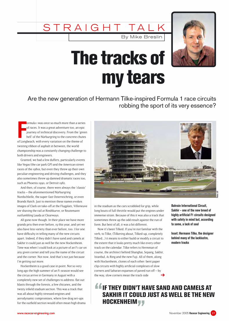
Bahrain International Circuit,
Sakhir – one of the new breed of
highly artifi cial F1 circuits designed
with safety in mind but, according
to some, a lack of soul
Inset: Hermann Tilke, the designer
behind many of the lacklustre,
modern tracks
➔
Phot
os: L
AT
27www.racecar-engineering.com
S T R A I G H T T A L KBy Mike Breslin
advertising is on camera for longer, but that’s surely
just a coincidence... Isn’t it?
To be fair to Herr Tilke, he’s just following a brief,
and perhaps the reason why these circuits tend to look
the same is because, by and large, they do actually
allow for more overtaking, and some of the dicing at
Sakhir, Sepang and Hockenheim has in fact been
pretty good stuff. And yet, there’s something missing.
It all seems so artifi cial.
Why? Well, think about the most memorable
overtaking moves of recent times: Montoya on
Schumacher at Interlagos. Hakkinen on Schumacher at
Spa. Barrichello on Raikkonen at Silverstone. What
have they in common? They all happened on real
circuits. In fact, I reckon one pass at Spa is equal to
about fi ve at Sepang or the like. It’s because the moves
you remember best take place at tracks where to
overtake is still a huge challenge, but most
Some people don’t agree though. The other day I
was reading a report that said Formula 1 should even
re-brand itself as the ‘safest extreme sport in the
world.’ Only a sport as out of touch with the real world
as F1 could ever come up with something as ridiculous
as that. Why would anyone want to watch an extreme
sport that wasn’t extreme? That’s just extremely dull.
I’m not saying we should make all the circuits more
dangerous here, and there’s no way F1 would or could
for very many reasons, not least involving the legal
implications should the worst happen. But just maybe
we have gone far enough, just maybe it’s time to stop
building new circuits and to start looking after what’s
left of F1’s once proud heritage of challenging
autodromes and differing engineering challenges from
track to track. After all, in these days of increasing pre-
race simulation – some of the teams have fi nished the
race before they get to the track – the older, real
tracks, particularly impermanent facilities like Monaco
and Montreal, offer something a baby’s-behind
smooth Tilke-drome can’t – bumpy surfaces that can
change in character year on year. Which surely must
add to the challenge from an engineering standpoint?
So then, with all that in mind, what’s my 2006
calendar? Melbourne, Imola, Monaco, Nürburgring
(funny isn’t it, we used to think that place was bad),
Silverstone, Montreal, Indy (it’s different at least), Spa,
Monza, Suzuka, Interlagos, Jerez, Estoril, Donington
(please!) and just a couple of those Tilke go-kart tracks
– Sepang and Hockenheim perhaps, but with gravel
traps instead of hard aprons.
Just a dream, of course, for the cigarette money says
we have to head east, and chances are that each new
GP will be on a purpose-built track cut from the same
cloth as all the others. Actually, some think this suits
the little big man in charge of F1 perfectly. For there is
nothing Bernie Ecclestone likes better than order and
uniformity – so maybe this is all part of his master plan
to make F1 fi t the Bernie mould? If that’s the case,
here’s a cheaper way: what about 20 races, all held at
Shanghai? And maybe we could have the exact same
race each time, too – that would save us the bother of
having to tune in.
“ I RECKON ONE PASS AT SPA IS EQUAL TO ABOUT FIVE AT SEPANG OR THE LIKE
”importantly perhaps, at circuits where there is an
element of jeopardy if the move should go amiss. And
that’s important. At this year’s Bahrain Grand Prix
Mark Webber made a mistake and went sailing off the
track – I forget which corner, they all look the same.
He didn’t seem to fi ght the car, he just let it go, to save
the tyres I guess and that’s fair enough. But the point
is, nothing happened. The car just switched from one
ultra smooth surface to another – paved run-off – and
in the course of his ‘incident’ Webber almost explored
as much of the Arabian peninsula as Wilfred Thesiger.
There was not even a gravel trap to ruin his day.
Now to me this seems wrong. Drivers at the highest
level should be punished if they make a mistake,
because it’s the treading of the thin line between
success and disaster that is the very essence of our
sport. A car on opposite lock through The Swimming
Pool Complex at Monaco is 10 times more exciting than
the same at some anonymous Tilke turn with an empty
lorry park for run-off. RE
November 2005 Racecar Engineering28 www.racecar-engineering.com
Straight talk
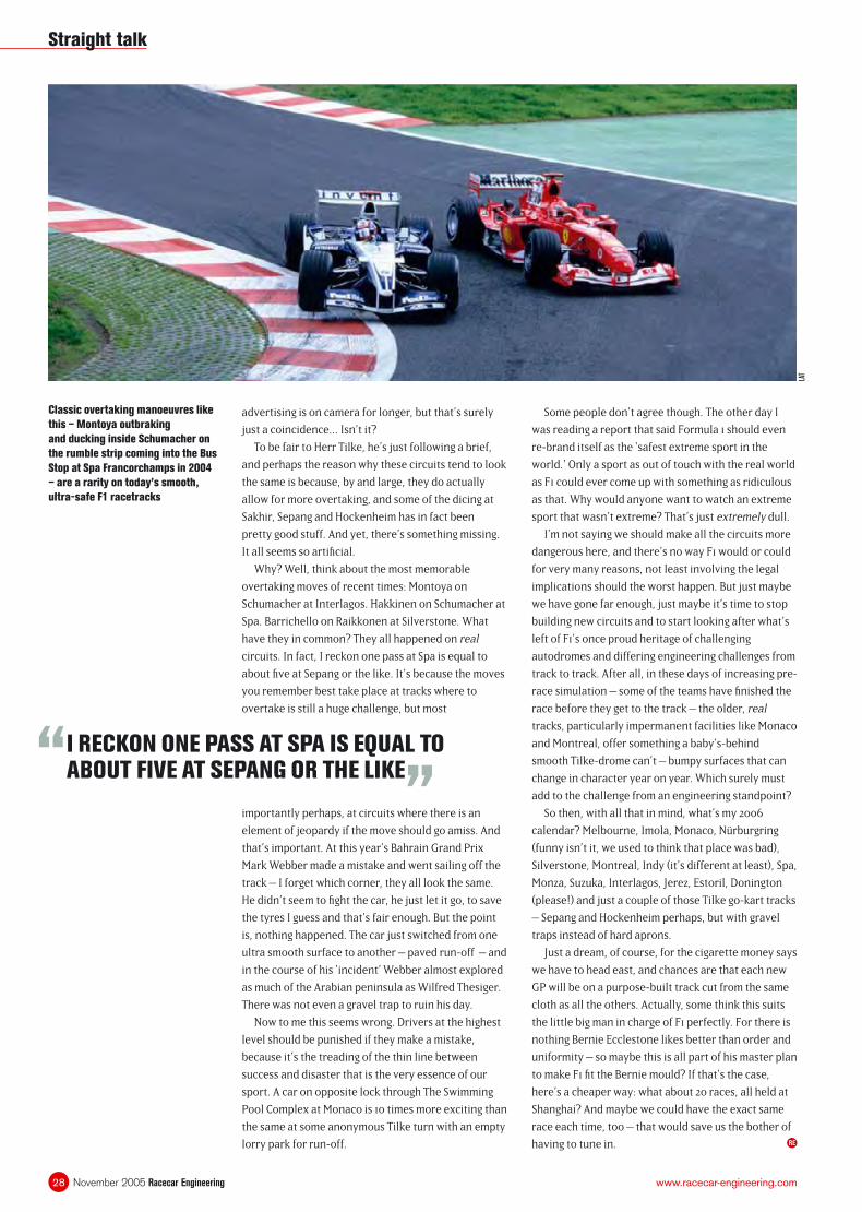
Classic overtaking manoeuvres like
this – Montoya outbraking
and ducking inside Schumacher on
the rumble strip coming into the Bus
Stop at Spa Francorchamps in 2004
– are a rarity on today’s smooth,
ultra-safe F1 racetracks
LAT
31November 2005 Racecar Engineeringwww.racecar-engineering.com
Forum
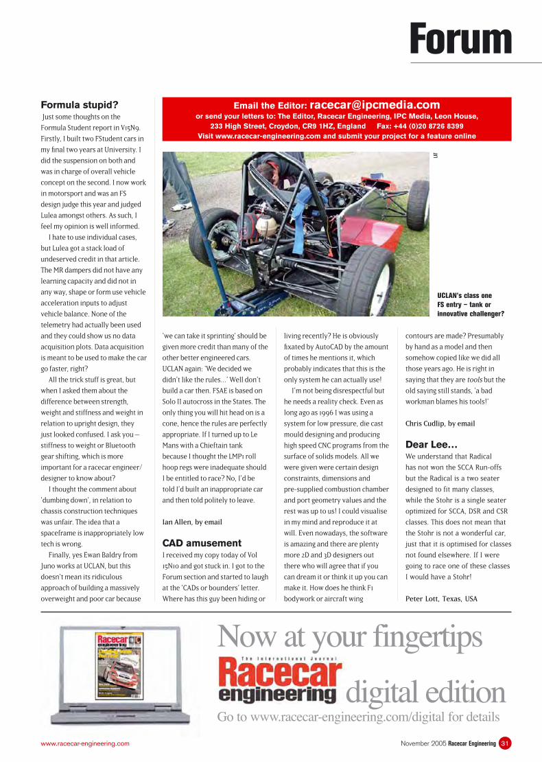
UCLAN’s class one
FS entry – tank or
innovative challenger?
Email the Editor: [email protected] send your letters to: The Editor, Racecar Engineering, IPC Media, Leon House,
233 High Street, Croydon, CR9 1HZ, England Fax: +44 (0)20 8726 8399Visit www.racecar-engineering.com and submit your project for a feature online
LAT
Now at your fingertips
digital editionGo to www.racecar-engineering.com/digital for details
Formula stupid? Just some thoughts on the
Formula Student report in V15N9.
Firstly, I built two FStudent cars in
my fi nal two years at University. I
did the suspension on both and
was in charge of overall vehicle
concept on the second. I now work
in motorsport and was an FS
design judge this year and judged
Lulea amongst others. As such, I
feel my opinion is well informed.
I hate to use individual cases,
but Lulea got a stack load of
undeserved credit in that article.
The MR dampers did not have any
learning capacity and did not in
any way, shape or form use vehicle
acceleration inputs to adjust
vehicle balance. None of the
telemetry had actually been used
and they could show us no data
acquisition plots. Data acquisition
is meant to be used to make the car
go faster, right?
All the trick stuff is great, but
when I asked them about the
difference between strength,
weight and stiffness and weight in
relation to upright design, they
just looked confused. I ask you –
stiffness to weight or Bluetooth
gear shifting, which is more
important for a racecar engineer/
designer to know about?
I thought the comment about
‘dumbing down’, in relation to
chassis construction techniques
was unfair. The idea that a
spaceframe is inappropriately low
tech is wrong.
Finally, yes Ewan Baldry from
Juno works at UCLAN, but this
doesn’t mean its ridiculous
approach of building a massively
overweight and poor car because
contours are made? Presumably
by hand as a model and then
somehow copied like we did all
those years ago. He is right in
saying that they are tools but the
old saying still stands, ‘a bad
workman blames his tools!’
Chris Cudlip, by email
Dear Lee…We understand that Radical
has not won the SCCA Run-offs
but the Radical is a two seater
designed to fit many classes,
while the Stohr is a single seater
optimized for SCCA, DSR and CSR
classes. This does not mean that
the Stohr is not a wonderful car,
just that it is optimised for classes
not found elsewhere. If I were
going to race one of these classes
I would have a Stohr!
Peter Lott, Texas, USA
‘we can take it sprinting’ should be
given more credit than many of the
other better engineered cars.
UCLAN again: ‘We decided we
didn’t like the rules…’ Well don’t
build a car then. FSAE is based on
Solo II autocross in the States. The
only thing you will hit head on is a
cone, hence the rules are perfectly
appropriate. If I turned up to Le
Mans with a Chieftain tank
because I thought the LMP1 roll
hoop regs were inadequate should
I be entitled to race? No, I’d be
told I’d built an inappropriate car
and then told politely to leave.
Ian Allen, by email
CAD amusementI received my copy today of Vol
15N10 and got stuck in. I got to the
Forum section and started to laugh
at the ‘CADs or bounders’ letter.
Where has this guy been hiding or
living recently? He is obviously
fi xated by AutoCAD by the amount
of times he mentions it, which
probably indicates that this is the
only system he can actually use!
I’m not being disrespectful but
he needs a reality check. Even as
long ago as 1996 I was using a
system for low pressure, die cast
mould designing and producing
high speed CNC programs from the
surface of solids models. All we
were given were certain design
constraints, dimensions and
pre-supplied combustion chamber
and port geometry values and the
rest was up to us! I could visualise
in my mind and reproduce it at
will. Even nowadays, the software
is amazing and there are plenty
more 2D and 3D designers out
there who will agree that if you
can dream it or think it up you can
make it. How does he think F1
bodywork or aircraft wing
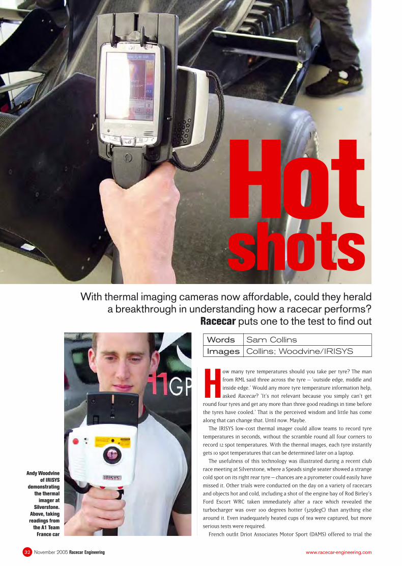
Hot shots
With thermal imaging cameras now affordable, could they herald a breakthrough in understanding how a racecar performs?
Racecar puts one to the test to fi nd out
Words Sam Collins
Images Collins; Woodvine/IRISYS
How many tyre temperatures should you take per tyre? The man
from RML said three across the tyre – ‘outside edge, middle and
inside edge.’ Would any more tyre temperature information help,
asked Racecar? ‘It’s not relevant because you simply can’t get
round four tyres and get any more than three good readings in time before
the tyres have cooled.’ That is the perceived wisdom and little has come
along that can change that. Until now. Maybe.
The IRISYS low-cost thermal imager could allow teams to record tyre
temperatures in seconds, without the scramble round all four corners to
record 12 spot temperatures. With the thermal images, each tyre instantly
gets 10 spot temperatures that can be determined later on a laptop.
The usefulness of this technology was illustrated during a recent club
race meeting at Silverstone, where a Speads single seater showed a strange
cold spot on its right rear tyre – chances are a pyrometer could easily have
missed it. Other trials were conducted on the day on a variety of racecars
and objects hot and cold, including a shot of the engine bay of Rod Birley’s
Ford Escort WRC taken immediately after a race which revealed the
turbocharger was over 100 degrees hotter (325degC) than anything else
around it. Even inadequately heated cups of tea were captured, but more
serious tests were required.
French outfi t Driot Associates Motor Sport (DAMS) offered to trial the
November 2005 Racecar Engineering32 www.racecar-engineering.com
Andy Woodvine
of IRISYS
demonstrating
the thermal
imager at
Silverstone.
Above, taking
readings from
the A1 Team
France car

technology on the tyres and brakes of its GP2 and A1GP Cars, offering a
direct comparison with the usual probe-type pyrometers. One of the team
engineers commented: ‘It is good because when you have images you can
instantly view the situation. With a probe you must look at just the
numbers.’ The competitive spirit was soon present as it became clear that
the imager could be used to establish what the competition is up to as well.
‘It would be great in a series like GP2 because you can see what your
competitors’ tyres are doing without touching them or even being that near
to the car.’ Something Racecar put to the test earlier in the day, walking in
the back of one team’s garage and taking temperature readings from
several metres away without being challenged. IRISYS representative (and
Formula Vee racer) Andy Woodvine claims ‘it’s accurate from -10degC to
300degC, so it quickly gives you a snap shot of the whole temperature range
of the desired area.’
Head-to-head testing started on the A1 Team France car run by DAMS.
AP Racing’s Nic Olsen used a traditional tyre probe to take readings from the
car’s brake discs, registering a spot temperature of 260degC, while the
thermal imager only recorded a temperature of 160degC, around 100degC
out. It seemed Woodvine’s claims were somewhat optimistic, but Olsen had
the answer: ‘On carbon discs it would work fi ne because they are a black
body, but once you get a shiny steel disc it can be a couple of hundred
Thermal imaging
33November 2005 Racecar Engineeringwww.racecar-engineering.com
“ IT COULD ALLOW TEAMS TO RECORD TYRE TEMPERATURES IN SECONDS
”
Right rear tyre of A1 Team Mexico’s Lola just after removal of tyre blankets.
Uneven heating is clearly evident, with nearly 10 degrees of fl uctuation.
Particularly of note are the hot and cold spots left on the tyre
Getting the right emissivity value for a surface is key to obtaining an accurate
reading. The IRISYS thermal imager comes with a number of preset values but
currently none specifi cally for motorsport applications
Taking 10 temperatures across a tyre is easy with the thermal imager. But
spot tyre temperatures are perhaps redundant with an overall visual image
Right rear tyre of a Speads RM05 taken in parc ferme after a 10-lap club race
on Silverstone’s National circuit. Note the cool stripe on the left running the
entire circumference of the tyre. Although it was only a two-degree difference
it could point to a number of problems, including a tyre defect. Interference
from the engine and exhaust is unlikely as the problem did not manifest on
two other identical cars racing at the same event
“ EMISSIVITY IS THE RATIO OF RADIATION EMITTED BY A SURFACE
”
➔
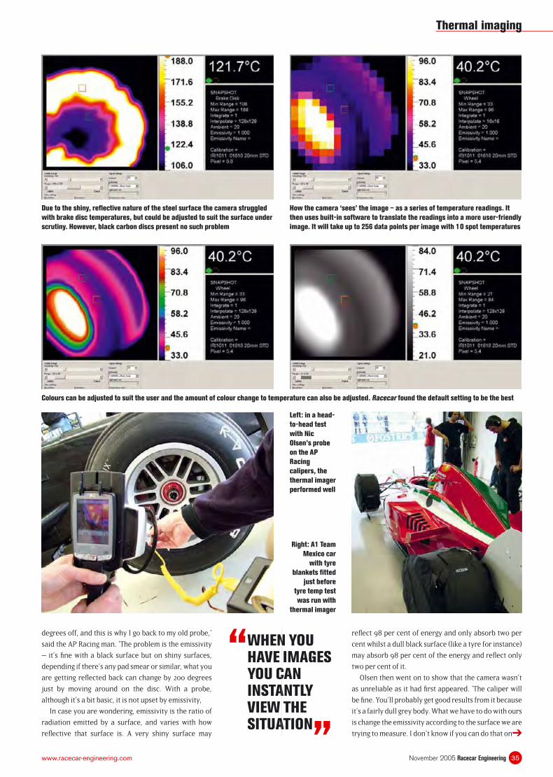
degrees off, and this is why I go back to my old probe,’
said the AP Racing man. ‘The problem is the emissivity
– it’s fi ne with a black surface but on shiny surfaces,
depending if there’s any pad smear or similar, what you
are getting refl ected back can change by 200 degrees
just by moving around on the disc. With a probe,
although it’s a bit basic, it is not upset by emissivity,
In case you are wondering, emissivity is the ratio of
radiation emitted by a surface, and varies with how
refl ective that surface is. A very shiny surface may
“ WHEN YOU HAVE IMAGES YOU CAN INSTANTLY VIEW THE SITUATION
”
refl ect 98 per cent of energy and only absorb two per
cent whilst a dull black surface (like a tyre for instance)
may absorb 98 per cent of the energy and refl ect only
two per cent of it.
Olsen then went on to show that the camera wasn’t
as unreliable as it had fi rst appeared. ‘The caliper will
be fi ne. You’ll probably get good results from it because
it’s a fairly dull grey body. What we have to do with ours
is change the emissivity according to the surface we are
trying to measure. I don’t know if you can do that on
Thermal imaging
35November 2005 Racecar Engineeringwww.racecar-engineering.com
Left: in a head-
to-head test
with Nic
Olsen’s probe
on the AP
Racing
calipers, the
thermal imager
performed well
Right: A1 Team
Mexico car
with tyre
blankets fi tted
just before
tyre temp test
was run with
thermal imager
Colours can be adjusted to suit the user and the amount of colour change to temperature can also be adjusted. Racecar found the default setting to be the best
Due to the shiny, refl ective nature of the steel surface the camera struggled
with brake disc temperatures, but could be adjusted to suit the surface under
scrutiny. However, black carbon discs present no such problem
How the camera ‘sees’ the image – as a series of temperature readings. It
then uses built-in software to translate the readings into a more user-friendly
image. It will take up to 256 data points per image with 10 spot temperatures
➔
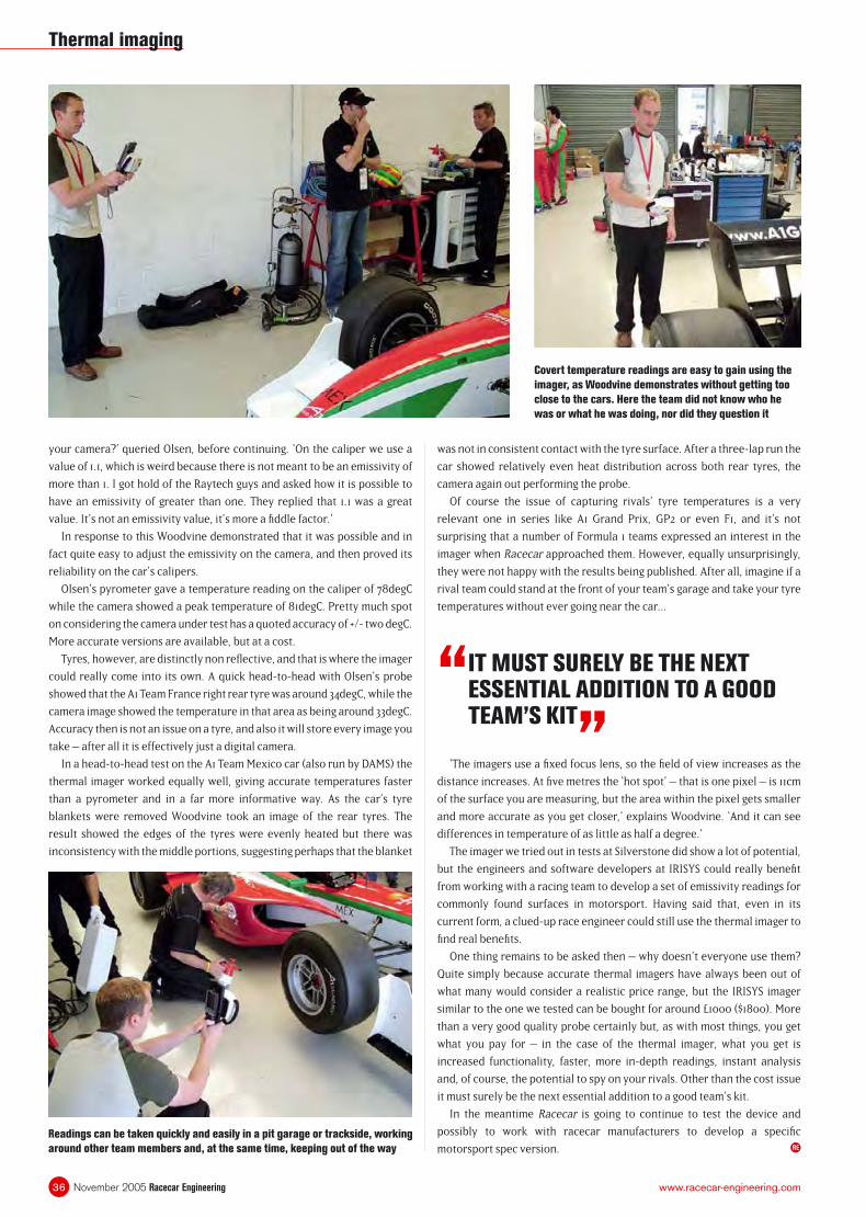
your camera?’ queried Olsen, before continuing. ‘On the caliper we use a
value of 1.1, which is weird because there is not meant to be an emissivity of
more than 1. I got hold of the Raytech guys and asked how it is possible to
have an emissivity of greater than one. They replied that 1.1 was a great
value. It’s not an emissivity value, it’s more a fi ddle factor.’
In response to this Woodvine demonstrated that it was possible and in
fact quite easy to adjust the emissivity on the camera, and then proved its
reliability on the car’s calipers.
Olsen’s pyrometer gave a temperature reading on the caliper of 78degC
while the camera showed a peak temperature of 81degC. Pretty much spot
on considering the camera under test has a quoted accuracy of +/- two degC.
More accurate versions are available, but at a cost.
Tyres, however, are distinctly non refl ective, and that is where the imager
could really come into its own. A quick head-to-head with Olsen’s probe
showed that the A1 Team France right rear tyre was around 34degC, while the
camera image showed the temperature in that area as being around 33degC.
Accuracy then is not an issue on a tyre, and also it will store every image you
take – after all it is effectively just a digital camera.
In a head-to-head test on the A1 Team Mexico car (also run by DAMS) the
thermal imager worked equally well, giving accurate temperatures faster
than a pyrometer and in a far more informative way. As the car’s tyre
blankets were removed Woodvine took an image of the rear tyres. The
result showed the edges of the tyres were evenly heated but there was
inconsistency with the middle portions, suggesting perhaps that the blanket
was not in consistent contact with the tyre surface. After a three-lap run the
car showed relatively even heat distribution across both rear tyres, the
camera again out performing the probe.
Of course the issue of capturing rivals’ tyre temperatures is a very
relevant one in series like A1 Grand Prix, GP2 or even F1, and it’s not
surprising that a number of Formula 1 teams expressed an interest in the
imager when Racecar approached them. However, equally unsurprisingly,
they were not happy with the results being published. After all, imagine if a
rival team could stand at the front of your team’s garage and take your tyre
temperatures without ever going near the car...
Thermal imaging
November 2005 Racecar Engineering36 www.racecar-engineering.com
“ IT MUST SURELY BE THE NEXT ESSENTIAL ADDITION TO A GOOD TEAM’S KIT
”
Covert temperature readings are easy to gain using the
imager, as Woodvine demonstrates without getting too
close to the cars. Here the team did not know who he
was or what he was doing, nor did they question it
Readings can be taken quickly and easily in a pit garage or trackside, working
around other team members and, at the same time, keeping out of the way
‘The imagers use a fi xed focus lens, so the fi eld of view increases as the
distance increases. At fi ve metres the ‘hot spot’ – that is one pixel – is 11cm
of the surface you are measuring, but the area within the pixel gets smaller
and more accurate as you get closer,’ explains Woodvine. ‘And it can see
differences in temperature of as little as half a degree.’
The imager we tried out in tests at Silverstone did show a lot of potential,
but the engineers and software developers at IRISYS could really benefi t
from working with a racing team to develop a set of emissivity readings for
commonly found surfaces in motorsport. Having said that, even in its
current form, a clued-up race engineer could still use the thermal imager to
fi nd real benefi ts.
One thing remains to be asked then – why doesn’t everyone use them?
Quite simply because accurate thermal imagers have always been out of
what many would consider a realistic price range, but the IRISYS imager
similar to the one we tested can be bought for around £1000 ($1800). More
than a very good quality probe certainly but, as with most things, you get
what you pay for – in the case of the thermal imager, what you get is
increased functionality, faster, more in-depth readings, instant analysis
and, of course, the potential to spy on your rivals. Other than the cost issue
it must surely be the next essential addition to a good team’s kit.
In the meantime Racecar is going to continue to test the device and
possibly to work with racecar manufacturers to develop a specifi c
motorsport spec version. RE
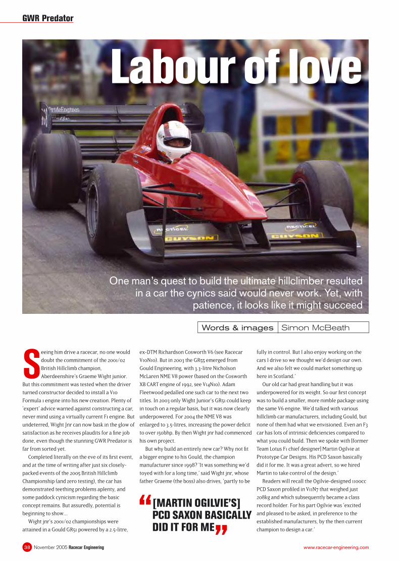
November 2005 Racecar Engineering38 www.racecar-engineering.com
Labour of love
One man’s quest to build the ultimate hillclimber resulted in a car the cynics said would never work. Yet, with
patience, it looks like it might succeed
Words & images Simon McBeath
Seeing him drive a racecar, no one would
doubt the commitment of the 2001/02
British Hillclimb champion,
Aberdeenshire’s Graeme Wight junior.
But this commitment was tested when the driver
turned constructor decided to install a V10
Formula 1 engine into his new creation. Plenty of
‘expert’ advice warned against constructing a car,
never mind using a virtually current F1 engine. But
undeterred, Wight Jnr can now bask in the glow of
satisfaction as he receives plaudits for a fi ne job
done, even though the stunning GWR Predator is
far from sorted yet.
Completed literally on the eve of its fi rst event,
and at the time of writing after just six closely-
packed events of the 2005 British Hillclimb
Championship (and zero testing), the car has
demonstrated teething problems aplenty, and
some paddock cynicism regarding the basic
concept remains. But assuredly, potential is
beginning to show...
Wight jnr’s 2001/02 championships were
attained in a Gould GR51 powered by a 2.5-litre,
ex-DTM Richardson Cosworth V6 (see Racecar
V10N10). But in 2003 the GR55 emerged from
Gould Engineering, with 3.3-litre Nicholson
McLaren NME V8 power (based on the Cosworth
XB CART engine of 1992, see V14N10). Adam
Fleetwood pedalled one such car to the next two
titles. In 2003 only Wight Junior’s GR51 could keep
in touch on a regular basis, but it was now clearly
underpowered. For 2004 the NME V8 was
enlarged to 3.5-litres, increasing the power defi cit
to over 150bhp. By then Wight jnr had commenced
his own project.
But why build an entirely new car? Why not fi t
a bigger engine to his Gould, the champion
manufacturer since 1998? ‘It was something we’d
toyed with for a long time,’ said Wight jnr, whose
father Graeme (the boss) also drives, ‘partly to be
fully in control. But I also enjoy working on the
cars I drive so we thought we’d design our own.
And we also felt we could market something up
here in Scotland.’
Our old car had great handling but it was
underpowered for its weight. So our fi rst concept
was to build a smaller, more nimble package using
the same V6 engine. We’d talked with various
hillclimb car manufacturers, including Gould, but
none of them had what we envisioned. Even an F3
car has lots of intrinsic defi ciencies compared to
what you could build. Then we spoke with [former
Team Lotus F1 chief designer] Martin Ogilvie at
Prototype Car Designs. His PCD Saxon basically
did it for me. It was a great advert, so we hired
Martin to take control of the design.’
Readers will recall the Ogilvie-designed 1100cc
PCD Saxon profi led in V11N7 that weighed just
208kg and which subsequently became a class
record holder. For his part Ogilvie was ‘excited
and pleased to be asked, in preference to the
established manufacturers, by the then current
champion to design a car.’
“ [MARTIN OGILVIE’S] PCD SAXON BASICALLY DID IT FOR ME
”
GWR Predator
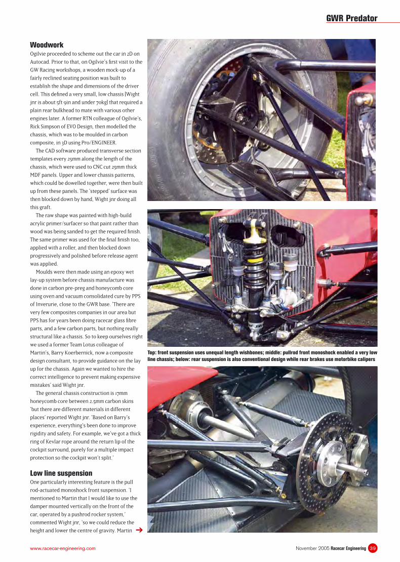
39November 2005 Racecar Engineeringwww.racecar-engineering.com
WoodworkOgilvie proceeded to scheme out the car in 2D on
Autocad. Prior to that, on Ogilvie’s fi rst visit to the
GW Racing workshops, a wooden mock-up of a
fairly reclined seating position was built to
establish the shape and dimensions of the driver
cell. This defi ned a very small, low chassis [Wight
jnr is about 5ft 9in and under 70kg] that required a
plain rear bulkhead to mate with various other
engines later. A former RTN colleague of Ogilvie’s,
Rick Simpson of EVO Design, then modelled the
chassis, which was to be moulded in carbon
composite, in 3D using Pro/ENGINEER.
The CAD software produced transverse section
templates every 25mm along the length of the
chassis, which were used to CNC cut 25mm thick
MDF panels. Upper and lower chassis patterns,
which could be dowelled together, were then built
up from these panels. The ‘stepped’ surface was
then blocked down by hand, Wight jnr doing all
this graft.
The raw shape was painted with high-build
acrylic primer/surfacer so that paint rather than
wood was being sanded to get the required fi nish.
The same primer was used for the fi nal fi nish too,
applied with a roller, and then blocked down
progressively and polished before release agent
was applied.
Moulds were then made using an epoxy wet
lay-up system before chassis manufacture was
done in carbon pre-preg and honeycomb core
using oven and vacuum consolidated cure by PPS
of Inverurie, close to the GWR base. ‘There are
very few composites companies in our area but
PPS has for years been doing racecar glass fi bre
parts, and a few carbon parts, but nothing really
structural like a chassis. So to keep ourselves right
we used a former Team Lotus colleague of
Martin’s, Barry Koerbernick, now a composite
design consultant, to provide guidance on the lay
up for the chassis. Again we wanted to hire the
correct intelligence to prevent making expensive
mistakes’ said Wight jnr.
The general chassis construction is 17mm
honeycomb core between 2.5mm carbon skins
‘but there are different materials in different
places’ reported Wight jnr. ‘Based on Barry’s
experience, everything’s been done to improve
rigidity and safety. For example, we’ve got a thick
ring of Kevlar rope around the return lip of the
cockpit surround, purely for a multiple impact
protection so the cockpit won’t split.’
Low line suspensionOne particularly interesting feature is the pull
rod-actuated monoshock front suspension. ‘I
mentioned to Martin that I would like to use the
damper mounted vertically on the front of the
car, operated by a pushrod rocker system,’
commented Wight jnr, ‘so we could reduce the
height and lower the centre of gravity. Martin ➔
Top: front suspension uses unequal length wishbones; middle: pullrod front monoshock enabled a very low
line chassis; below: rear suspension is also conventional design while rear brakes use motorbike calipers
GWR Predator
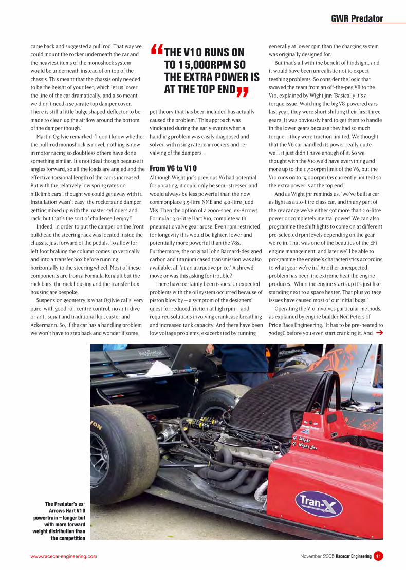
41November 2005 Racecar Engineeringwww.racecar-engineering.com
came back and suggested a pull rod. That way we
could mount the rocker underneath the car and
the heaviest items of the monoshock system
would be underneath instead of on top of the
chassis. This meant that the chassis only needed
to be the height of your feet, which let us lower
the line of the car dramatically, and also meant
we didn’t need a separate top damper cover.
There is still a little bulge shaped-defl ector to be
made to clean up the airfl ow around the bottom
of the damper though.’
Martin Ogilvie remarked: ‘I don’t know whether
the pull-rod monoshock is novel, nothing is new
in motor racing so doubtless others have done
something similar. It’s not ideal though because it
angles forward, so all the loads are angled and the
effective torsional length of the car is increased.
But with the relatively low spring rates on
hillclimb cars I thought we could get away with it.
Installation wasn’t easy, the rockers and damper
getting mixed up with the master cylinders and
rack, but that’s the sort of challenge I enjoy!’
Indeed, in order to put the damper on the front
bulkhead the steering rack was located inside the
chassis, just forward of the pedals. To allow for
left foot braking the column comes up vertically
and into a transfer box before running
horizontally to the steering wheel. Most of these
components are from a Formula Renault but the
rack bars, the rack housing and the transfer box
housing are bespoke.
Suspension geometry is what Ogilvie calls ‘very
pure, with good roll centre control, no anti-dive
or anti-squat and traditional kpi, caster and
Ackermann. So, if the car has a handling problem
we won’t have to step back and wonder if some
pet theory that has been included has actually
caused the problem.’ This approach was
vindicated during the early events when a
handling problem was easily diagnosed and
solved with rising rate rear rockers and re-
valving of the dampers.
From V6 to V10Although Wight jnr’s previous V6 had potential
for uprating, it could only be semi-stressed and
would always be less powerful than the now
commonplace 3.5-litre NME and 4.0-litre Judd
V8s. Then the option of a 2000-spec, ex-Arrows
Formula 1 3.0-litre Hart V10, complete with
pneumatic valve gear arose. Even rpm restricted
for longevity this would be lighter, lower and
potentially more powerful than the V8s.
Furthermore, the original John Barnard-designed
carbon and titanium cased transmission was also
available, all ‘at an attractive price.’ A shrewd
move or was this asking for trouble?
There have certainly been issues. Unexpected
problems with the oil system occurred because of
piston blow by – a symptom of the designers’
quest for reduced friction at high rpm – and
required solutions involving crankcase breathing
and increased tank capacity. And there have been
low voltage problems, exacerbated by running
generally at lower rpm than the charging system
was originally designed for.
But that’s all with the benefi t of hindsight, and
it would have been unrealistic not to expect
teething problems. So consider the logic that
swayed the team from an off-the-peg V8 to the
V10, explained by Wight jnr: ‘Basically it’s a
torque issue. Watching the big V8-powered cars
last year, they were short shifting their fi rst three
gears. It was obviously hard to get them to handle
in the lower gears because they had so much
torque – they were traction limited. We thought
that the V6 car handled its power really quite
well; it just didn’t have enough of it. So we
thought with the V10 we’d have everything and
more up to the 11,500rpm limit of the V6, but the
V10 runs on to 15,000rpm (as currently limited) so
the extra power is at the top end.’
And as Wight jnr reminds us, ‘we’ve built a car
as light as a 2.0-litre class car, and in any part of
the rev range we’ve either got more than 2.0-litre
power or completely mental power! We can also
programme the shift lights to come on at different
pre-selected rpm levels depending on the gear
we’re in. That was one of the beauties of the EFi
engine management, and later we’ll be able to
programme the engine’s characteristics according
to what gear we’re in.’ Another unexpected
problem has been the extreme heat the engine
produces. ‘When the engine starts up it’s just like
standing next to a space heater. That plus voltage
issues have caused most of our initial bugs.’
Operating the V10 involves particular methods,
as explained by engine builder Neil Peters of
Pride Race Engineering: ‘It has to be pre-heated to
70degC before you even start cranking it. And ➔
“ THE V10 RUNS ON TO 15,000RPM SO THE EXTRA POWER IS AT THE TOP END
”
The Predator’s ex-
Arrows Hart V10
powertrain – longer but
with more forward
weight distribution than
the competition
GWR Predator
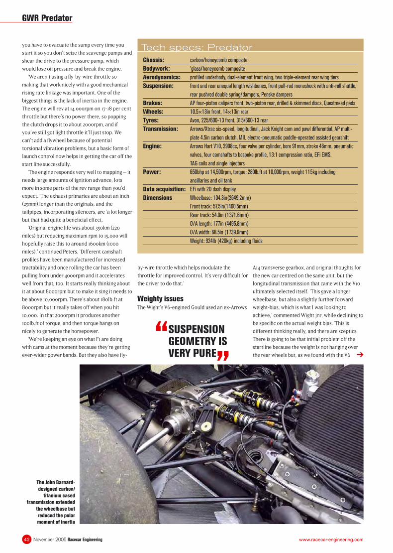
November 2005 Racecar Engineering42 www.racecar-engineering.com
you have to evacuate the sump every time you
start it so you don’t seize the scavenge pumps and
shear the drive to the pressure pump, which
would lose oil pressure and break the engine.
‘We aren’t using a fl y-by-wire throttle so
making that work nicely with a good mechanical
rising rate linkage was important. One of the
biggest things is the lack of inertia in the engine.
The engine will rev at 14,000rpm on 17-18 per cent
throttle but there’s no power there, so popping
the clutch drops it to about 2000rpm, and if
you’ve still got light throttle it’ll just stop. We
can’t add a fl ywheel because of potential
torsional vibration problems, but a basic form of
launch control now helps in getting the car off the
start line successfully.
‘The engine responds very well to mapping – it
needs large amounts of ignition advance, lots
more in some parts of the rev range than you’d
expect.’ The exhaust primaries are about an inch
(25mm) longer than the originals, and the
tailpipes, incorporating silencers, are ‘a lot longer
but that had quite a benefi cial effect.
‘Original engine life was about 350km (220
miles) but reducing maximum rpm to 15,000 will
hopefully raise this to around 1600km (1000
miles),’ continued Peters. ‘Different camshaft
profi les have been manufactured for increased
tractability and once rolling the car has been
pulling from under 4000rpm and it accelerates
well from that, too. It starts really thinking about
it at about 8000rpm but to make it sing it needs to
be above 10,000rpm. There’s about 180lb.ft at
8000rpm but it really takes off when you hit
10,000. In that 2000rpm it produces another
100lb.ft of torque, and then torque hangs on
nicely to generate the horsepower.
‘We’re keeping an eye on what F1 are doing
with cams at the moment because they’re getting
ever-wider power bands. But they also have fl y-
by-wire throttle which helps modulate the
throttle for improved control. It’s very diffi cult for
the driver to do that.’
Weighty issuesThe Wight’s V6-engined Gould used an ex-Arrows
A14 transverse gearbox, and original thoughts for
the new car centred on the same unit, but the
longitudinal transmission that came with the V10
ultimately selected itself. ‘This gave a longer
wheelbase, but also a slightly further forward
weight-bias, which is what I was looking to
achieve,’ commented Wight jnr, while declining to
be specifi c on the actual weight bias. ‘This is
different thinking really, and there are sceptics.
There is going to be that initial problem off the
startline because the weight is not hanging over
the rear wheels but, as we found with the V6 ➔
“ SUSPENSION GEOMETRY IS VERY PURE
”
Tech specs: PredatorChassis: carbon/honeycomb composite
Bodywork: ’glass/honeycomb composite
Aerodynamics: profi led underbody, dual-element front wing, two triple-element rear wing tiers
Suspension: front and rear unequal length wishbones, front pull-rod monoshock with anti-roll shuttle,
rear pushrod double spring/dampers, Penske dampers
Brakes: AP four-piston calipers front, two-piston rear, drilled & skimmed discs, Questmeed pads
Wheels: 10.5×13in front, 14×13in rear
Tyres: Avon, 225/600-13 front, 315/660-13 rear
Transmission: Arrows/Xtrac six-speed, longitudinal, Jack Knight cam and pawl differential, AP multi-
plate 4.5in carbon clutch, MIL electro-pneumatic paddle-operated assisted gearshift
Engine: Arrows Hart V10, 2998cc, four valve per cylinder, bore 91mm, stroke 46mm, pneumatic
valves, four camshafts to bespoke profi le, 13:1 compression ratio, EFi EMS,
TAG coils and single injectors
Power: 650bhp at 14,500rpm, torque: 280lb.ft at 10,000rpm, weight 115kg including
ancillaries and oil tank
Data acquisition: EFi with 2D dash display
Dimensions Wheelbase: 104.3in(2649.2mm)
Front track: 57.5in(1460.5mm)
Rear track: 54.0in (1371.6mm)
O/A length: 177in (4495.8mm)
O/A width: 68.5in (1739.9mm)
Weight: 924lb (420kg) including fl uids
The John Barnard-
designed carbon/
titanium cased
transmission extended
the wheelbase but
reduced the polar
moment of inertia
GWR Predator
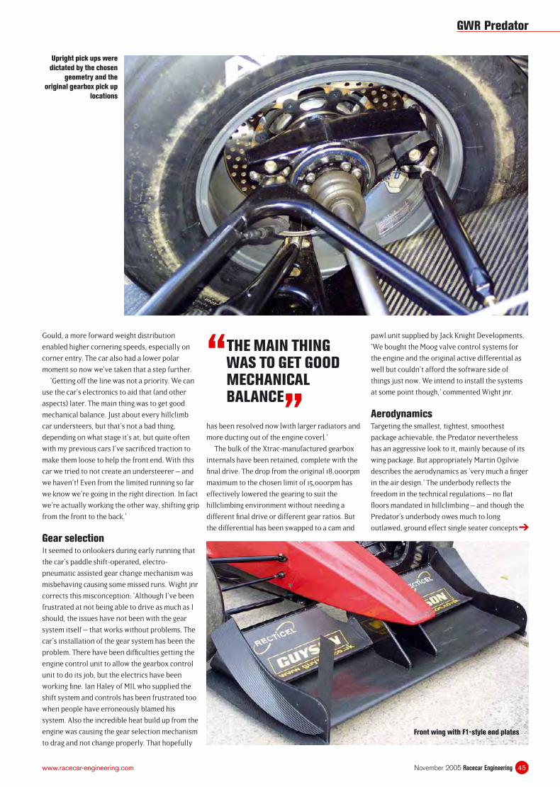
45November 2005 Racecar Engineeringwww.racecar-engineering.com
➔
“ THE MAIN THING WAS TO GET GOOD MECHANICAL BALANCE
”
Gould, a more forward weight distribution
enabled higher cornering speeds, especially on
corner entry. The car also had a lower polar
moment so now we’ve taken that a step further.
‘Getting off the line was not a priority. We can
use the car’s electronics to aid that (and other
aspects) later. The main thing was to get good
mechanical balance. Just about every hillclimb
car understeers, but that’s not a bad thing,
depending on what stage it’s at, but quite often
with my previous cars I’ve sacrifi ced traction to
make them loose to help the front end. With this
car we tried to not create an understeerer – and
we haven’t! Even from the limited running so far
we know we’re going in the right direction. In fact
we’re actually working the other way, shifting grip
from the front to the back.’
Gear selectionIt seemed to onlookers during early running that
the car’s paddle shift-operated, electro-
pneumatic assisted gear change mechanism was
misbehaving causing some missed runs. Wight jnr
corrects this misconception: ‘Although I’ve been
frustrated at not being able to drive as much as I
should, the issues have not been with the gear
system itself – that works without problems. The
car’s installation of the gear system has been the
problem. There have been diffi culties getting the
engine control unit to allow the gearbox control
unit to do its job, but the electrics have been
working fi ne. Ian Haley of MIL who supplied the
shift system and controls has been frustrated too
when people have erroneously blamed his
system. Also the incredible heat build up from the
engine was causing the gear selection mechanism
to drag and not change properly. That hopefully
has been resolved now [with larger radiators and
more ducting out of the engine cover].’
The bulk of the Xtrac-manufactured gearbox
internals have been retained, complete with the
fi nal drive. The drop from the original 18,000rpm
maximum to the chosen limit of 15,000rpm has
effectively lowered the gearing to suit the
hillclimbing environment without needing a
different fi nal drive or different gear ratios. But
the differential has been swapped to a cam and
pawl unit supplied by Jack Knight Developments.
‘We bought the Moog valve control systems for
the engine and the original active differential as
well but couldn’t afford the software side of
things just now. We intend to install the systems
at some point though,’ commented Wight jnr.
AerodynamicsTargeting the smallest, tightest, smoothest
package achievable, the Predator nevertheless
has an aggressive look to it, mainly because of its
wing package. But appropriately Martin Ogilvie
describes the aerodynamics as ‘very much a fi nger
in the air design.’ The underbody refl ects the
freedom in the technical regulations – no fl at
fl oors mandated in hillclimbing – and though the
Predator’s underbody owes much to long
outlawed, ground effect single seater concepts
Upright pick ups were
dictated by the chosen
geometry and the
original gearbox pick up
locations
Front wing with F1-style end plates
GWR Predator
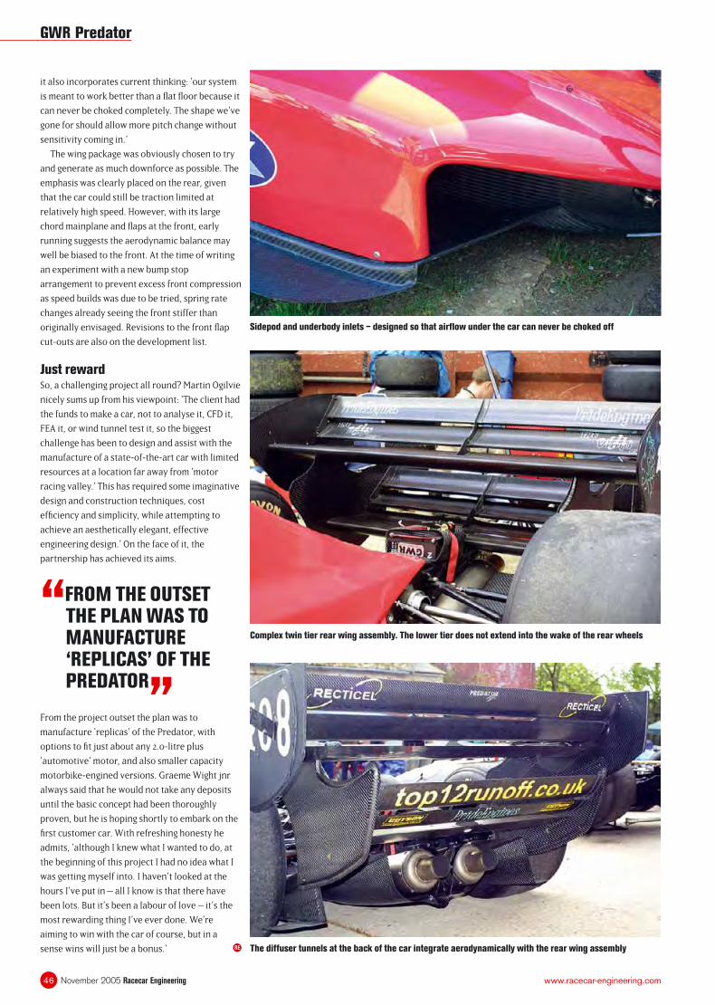
November 2005 Racecar Engineering46 www.racecar-engineering.com
it also incorporates current thinking: ‘our system
is meant to work better than a fl at fl oor because it
can never be choked completely. The shape we’ve
gone for should allow more pitch change without
sensitivity coming in.’
The wing package was obviously chosen to try
and generate as much downforce as possible. The
emphasis was clearly placed on the rear, given
that the car could still be traction limited at
relatively high speed. However, with its large
chord mainplane and fl aps at the front, early
running suggests the aerodynamic balance may
well be biased to the front. At the time of writing
an experiment with a new bump stop
arrangement to prevent excess front compression
as speed builds was due to be tried, spring rate
changes already seeing the front stiffer than
originally envisaged. Revisions to the front fl ap
cut-outs are also on the development list.
Just rewardSo, a challenging project all round? Martin Ogilvie
nicely sums up from his viewpoint: ‘The client had
the funds to make a car, not to analyse it, CFD it,
FEA it, or wind tunnel test it, so the biggest
challenge has been to design and assist with the
manufacture of a state-of-the-art car with limited
resources at a location far away from ‘motor
racing valley.’ This has required some imaginative
design and construction techniques, cost
effi ciency and simplicity, while attempting to
achieve an aesthetically elegant, effective
engineering design.’ On the face of it, the
partnership has achieved its aims.
RE
“FROM THE OUTSET THE PLAN WAS TO MANUFACTURE ‘REPLICAS’ OF THE PREDATOR
”From the project outset the plan was to
manufacture ‘replicas’ of the Predator, with
options to fi t just about any 2.0-litre plus
‘automotive’ motor, and also smaller capacity
motorbike-engined versions. Graeme Wight jnr
always said that he would not take any deposits
until the basic concept had been thoroughly
proven, but he is hoping shortly to embark on the
fi rst customer car. With refreshing honesty he
admits, ‘although I knew what I wanted to do, at
the beginning of this project I had no idea what I
was getting myself into. I haven’t looked at the
hours I’ve put in – all I know is that there have
been lots. But it’s been a labour of love – it’s the
most rewarding thing I’ve ever done. We’re
aiming to win with the car of course, but in a
sense wins will just be a bonus.’ The diffuser tunnels at the back of the car integrate aerodynamically with the rear wing assembly
Complex twin tier rear wing assembly. The lower tier does not extend into the wake of the rear wheels
Sidepod and underbody inlets – designed so that airfl ow under the car can never be choked off
GWR Predator
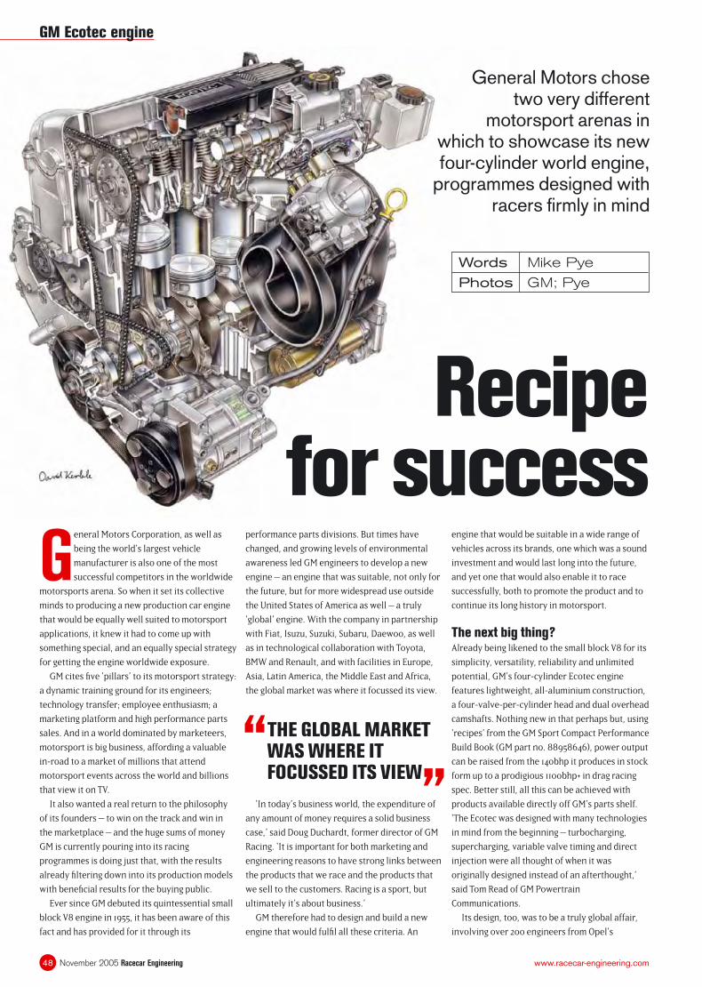
November 2005 Racecar Engineering48 www.racecar-engineering.com
Words Mike Pye
Photos GM; Pye
General Motors Corporation, as well as
being the world’s largest vehicle
manufacturer is also one of the most
successful competitors in the worldwide
motorsports arena. So when it set its collective
minds to producing a new production car engine
that would be equally well suited to motorsport
applications, it knew it had to come up with
something special, and an equally special strategy
for getting the engine worldwide exposure.
GM cites fi ve ‘pillars’ to its motorsport strategy:
a dynamic training ground for its engineers;
technology transfer; employee enthusiasm; a
marketing platform and high performance parts
sales. And in a world dominated by marketeers,
motorsport is big business, affording a valuable
in-road to a market of millions that attend
motorsport events across the world and billions
that view it on TV.
It also wanted a real return to the philosophy
of its founders – to win on the track and win in
the marketplace – and the huge sums of money
GM is currently pouring into its racing
programmes is doing just that, with the results
already fi ltering down into its production models
with benefi cial results for the buying public.
Ever since GM debuted its quintessential small
block V8 engine in 1955, it has been aware of this
fact and has provided for it through its
performance parts divisions. But times have
changed, and growing levels of environmental
awareness led GM engineers to develop a new
engine – an engine that was suitable, not only for
the future, but for more widespread use outside
the United States of America as well – a truly
‘global’ engine. With the company in partnership
with Fiat, Isuzu, Suzuki, Subaru, Daewoo, as well
as in technological collaboration with Toyota,
BMW and Renault, and with facilities in Europe,
Asia, Latin America, the Middle East and Africa,
the global market was where it focussed its view.
engine that would be suitable in a wide range of
vehicles across its brands, one which was a sound
investment and would last long into the future,
and yet one that would also enable it to race
successfully, both to promote the product and to
continue its long history in motorsport.
The next big thing?Already being likened to the small block V8 for its
simplicity, versatility, reliability and unlimited
potential, GM’s four-cylinder Ecotec engine
features lightweight, all-aluminium construction,
a four-valve-per-cylinder head and dual overhead
camshafts. Nothing new in that perhaps but, using
‘recipes’ from the GM Sport Compact Performance
Build Book (GM part no. 88958646), power output
can be raised from the 140bhp it produces in stock
form up to a prodigious 1100bhp+ in drag racing
spec. Better still, all this can be achieved with
products available directly off GM’s parts shelf.
‘The Ecotec was designed with many technologies
in mind from the beginning – turbocharging,
supercharging, variable valve timing and direct
injection were all thought of when it was
originally designed instead of an afterthought,’
said Tom Read of GM Powertrain
Communications.
Its design, too, was to be a truly global affair,
involving over 200 engineers from Opel’s
Recipe for success
General Motors chose two very different
motorsport arenas in which to showcase its new four-cylinder world engine,
programmes designed with racers fi rmly in mind
“ THE GLOBAL MARKET WAS WHERE IT FOCUSSED ITS VIEW
”‘In today’s business world, the expenditure of
any amount of money requires a solid business
case,’ said Doug Duchardt, former director of GM
Racing. ‘It is important for both marketing and
engineering reasons to have strong links between
the products that we race and the products that
we sell to the customers. Racing is a sport, but
ultimately it’s about business.’
GM therefore had to design and build a new
engine that would fulfi l all these criteria. An
GM Ecotec engine
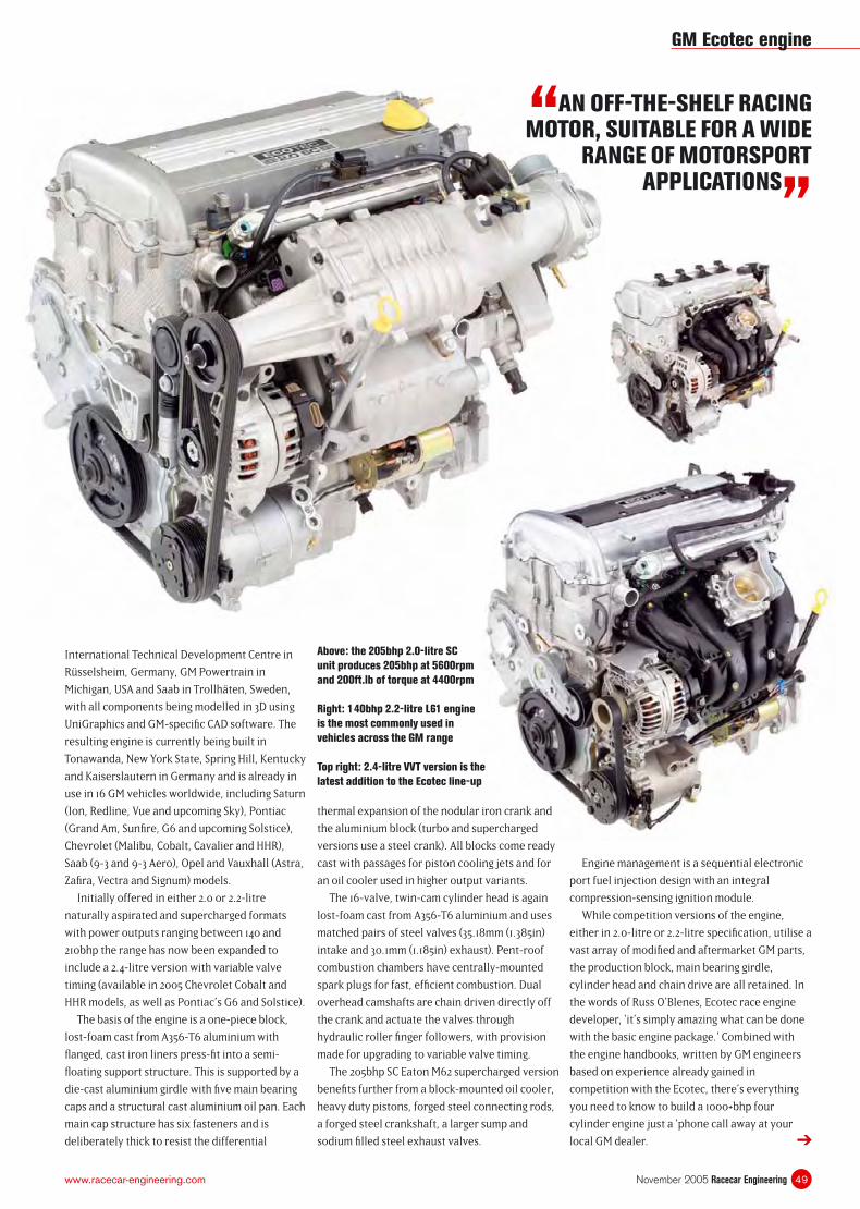
49November 2005 Racecar Engineeringwww.racecar-engineering.com
International Technical Development Centre in
Rüsselsheim, Germany, GM Powertrain in
Michigan, USA and Saab in Trollhäten, Sweden,
with all components being modelled in 3D using
UniGraphics and GM-specifi c CAD software. The
resulting engine is currently being built in
Tonawanda, New York State, Spring Hill, Kentucky
and Kaiserslautern in Germany and is already in
use in 16 GM vehicles worldwide, including Saturn
(Ion, Redline, Vue and upcoming Sky), Pontiac
(Grand Am, Sunfi re, G6 and upcoming Solstice),
Chevrolet (Malibu, Cobalt, Cavalier and HHR),
Saab (9-3 and 9-3 Aero), Opel and Vauxhall (Astra,
Zafi ra, Vectra and Signum) models.
Initially offered in either 2.0 or 2.2-litre
naturally aspirated and supercharged formats
with power outputs ranging between 140 and
210bhp the range has now been expanded to
include a 2.4-litre version with variable valve
timing (available in 2005 Chevrolet Cobalt and
HHR models, as well as Pontiac’s G6 and Solstice).
The basis of the engine is a one-piece block,
lost-foam cast from A356-T6 aluminium with
fl anged, cast iron liners press-fi t into a semi-
fl oating support structure. This is supported by a
die-cast aluminium girdle with fi ve main bearing
caps and a structural cast aluminium oil pan. Each
main cap structure has six fasteners and is
deliberately thick to resist the differential
thermal expansion of the nodular iron crank and
the aluminium block (turbo and supercharged
versions use a steel crank). All blocks come ready
cast with passages for piston cooling jets and for
an oil cooler used in higher output variants.
The 16-valve, twin-cam cylinder head is again
lost-foam cast from A356-T6 aluminium and uses
matched pairs of steel valves (35.18mm (1.385in)
intake and 30.1mm (1.185in) exhaust). Pent-roof
combustion chambers have centrally-mounted
spark plugs for fast, effi cient combustion. Dual
overhead camshafts are chain driven directly off
the crank and actuate the valves through
hydraulic roller fi nger followers, with provision
made for upgrading to variable valve timing.
The 205bhp SC Eaton M62 supercharged version
benefi ts further from a block-mounted oil cooler,
heavy duty pistons, forged steel connecting rods,
a forged steel crankshaft, a larger sump and
sodium fi lled steel exhaust valves.
Engine management is a sequential electronic
port fuel injection design with an integral
compression-sensing ignition module.
While competition versions of the engine,
either in 2.0-litre or 2.2-litre specifi cation, utilise a
vast array of modifi ed and aftermarket GM parts,
the production block, main bearing girdle,
cylinder head and chain drive are all retained. In
the words of Russ O’Blenes, Ecotec race engine
developer, ‘it’s simply amazing what can be done
with the basic engine package.’ Combined with
the engine handbooks, written by GM engineers
based on experience already gained in
competition with the Ecotec, there’s everything
you need to know to build a 1000+bhp four
cylinder engine just a ‘phone call away at your
local GM dealer.
“AN OFF-THE-SHELF RACING MOTOR, SUITABLE FOR A WIDE
RANGE OF MOTORSPORT APPLICATIONS
”
➔
Above: the 205bhp 2.0-litre SC
unit produces 205bhp at 5600rpm
and 200ft.lb of torque at 4400rpm
Right: 140bhp 2.2-litre L61 engine
is the most commonly used in
vehicles across the GM range
Top right: 2.4-litre VVT version is the
latest addition to the Ecotec line-up
GM Ecotec engine
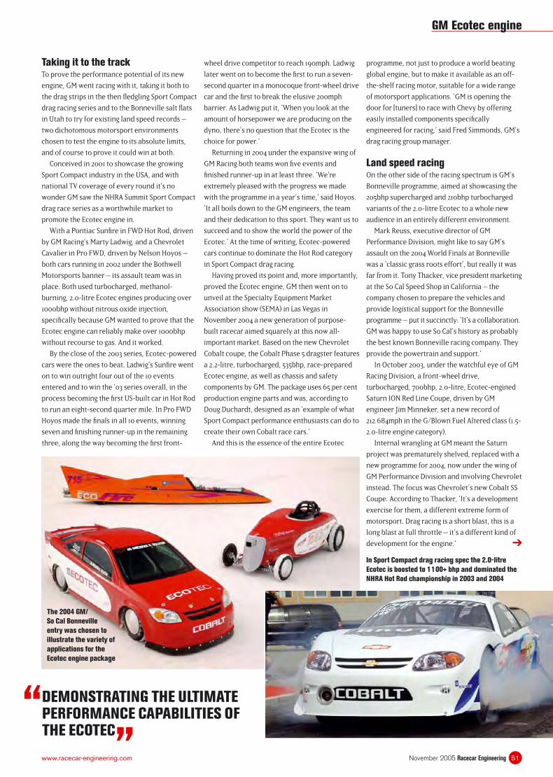
51November 2005 Racecar Engineeringwww.racecar-engineering.com
Taking it to the trackTo prove the performance potential of its new
engine, GM went racing with it, taking it both to
the drag strips in the then fl edgling Sport Compact
drag racing series and to the Bonneville salt fl ats
in Utah to try for existing land speed records –
two dichotomous motorsport environments
chosen to test the engine to its absolute limits,
and of course to prove it could win at both.
Conceived in 2001 to showcase the growing
Sport Compact industry in the USA, and with
national TV coverage of every round it’s no
wonder GM saw the NHRA Summit Sport Compact
drag race series as a worthwhile market to
promote the Ecotec engine in.
With a Pontiac Sunfi re in FWD Hot Rod, driven
by GM Racing’s Marty Ladwig, and a Chevrolet
Cavalier in Pro FWD, driven by Nelson Hoyos –
both cars running in 2002 under the Bothwell
Motorsports banner – its assault team was in
place. Both used turbocharged, methanol-
burning, 2.0-litre Ecotec engines producing over
1000bhp without nitrous oxide injection,
specifi cally because GM wanted to prove that the
Ecotec engine can reliably make over 1000bhp
without recourse to gas. And it worked.
By the close of the 2003 series, Ecotec-powered
cars were the ones to beat. Ladwig’s Sunfi re went
on to win outright four out of the 10 events
entered and to win the ‘03 series overall, in the
process becoming the fi rst US-built car in Hot Rod
to run an eight-second quarter mile. In Pro FWD
Hoyos made the fi nals in all 10 events, winning
seven and fi nishing runner-up in the remaining
three, along the way becoming the fi rst front-
wheel drive competitor to reach 190mph. Ladwig
later went on to become the fi rst to run a seven-
second quarter in a monocoque front-wheel drive
car and the fi rst to break the elusive 200mph
barrier. As Ladwig put it, ‘When you look at the
amount of horsepower we are producing on the
dyno, there’s no question that the Ecotec is the
choice for power.’
Returning in 2004 under the expansive wing of
GM Racing both teams won fi ve events and
fi nished runner-up in at least three. ‘We’re
extremely pleased with the progress we made
with the programme in a year’s time,’ said Hoyos.
‘It all boils down to the GM engineers, the team
and their dedication to this sport. They want us to
succeed and to show the world the power of the
Ecotec.’ At the time of writing, Ecotec-powered
cars continue to dominate the Hot Rod category
in Sport Compact drag racing.
Having proved its point and, more importantly,
proved the Ecotec engine, GM then went on to
unveil at the Specialty Equipment Market
Association show (SEMA) in Las Vegas in
November 2004 a new generation of purpose-
built racecar aimed squarely at this now all-
important market. Based on the new Chevrolet
Cobalt coupe, the Cobalt Phase 5 dragster features
a 2.2-litre, turbocharged, 535bhp, race-prepared
Ecotec engine, as well as chassis and safety
components by GM. The package uses 65 per cent
production engine parts and was, according to
Doug Duchardt, designed as an ‘example of what
Sport Compact performance enthusiasts can do to
create their own Cobalt race cars.’
And this is the essence of the entire Ecotec
programme, not just to produce a world beating
global engine, but to make it available as an off-
the-shelf racing motor, suitable for a wide range
of motorsport applications. ‘GM is opening the
door for [tuners] to race with Chevy by offering
easily installed components specifi cally
engineered for racing,’ said Fred Simmonds, GM’s
drag racing group manager.
Land speed racingOn the other side of the racing spectrum is GM’s
Bonneville programme, aimed at showcasing the
205bhp supercharged and 210bhp turbocharged
variants of the 2.0-litre Ecotec to a whole new
audience in an entirely different environment.
Mark Reuss, executive director of GM
Performance Division, might like to say GM’s
assault on the 2004 World Finals at Bonneville
was a ‘classic grass roots effort’, but really it was
far from it. Tony Thacker, vice president marketing
at the So Cal Speed Shop in California – the
company chosen to prepare the vehicles and
provide logistical support for the Bonneville
programme – put it succinctly: ‘It’s a collaboration.
GM was happy to use So Cal’s history as probably
the best known Bonneville racing company. They
provide the powertrain and support.’
In October 2003, under the watchful eye of GM
Racing Division, a front-wheel drive,
turbocharged, 700bhp, 2.0-litre, Ecotec-engined
Saturn ION Red Line Coupe, driven by GM
engineer Jim Minneker, set a new record of
212.684mph in the G/Blown Fuel Altered class (1.5-
2.0-litre engine category).
Internal wrangling at GM meant the Saturn
project was prematurely shelved, replaced with a
new programme for 2004, now under the wing of
GM Performance Division and involving Chevrolet
instead. The focus was Chevrolet’s new Cobalt SS
Coupe. According to Thacker, ‘It’s a development
exercise for them, a different extreme form of
motorsport. Drag racing is a short blast, this is a
long blast at full throttle – it’s a different kind of
development for the engine.’
“ DEMONSTRATING THE ULTIMATE PERFORMANCE CAPABILITIES OF THE ECOTEC
”
➔
The 2004 GM/
So Cal Bonneville
entry was chosen to
illustrate the variety of
applications for the
Ecotec engine package
GM Ecotec engine
In Sport Compact drag racing spec the 2.0-litre
Ecotec is boosted to 1100+ bhp and dominated the
NHRA Hot Rod championship in 2003 and 2004
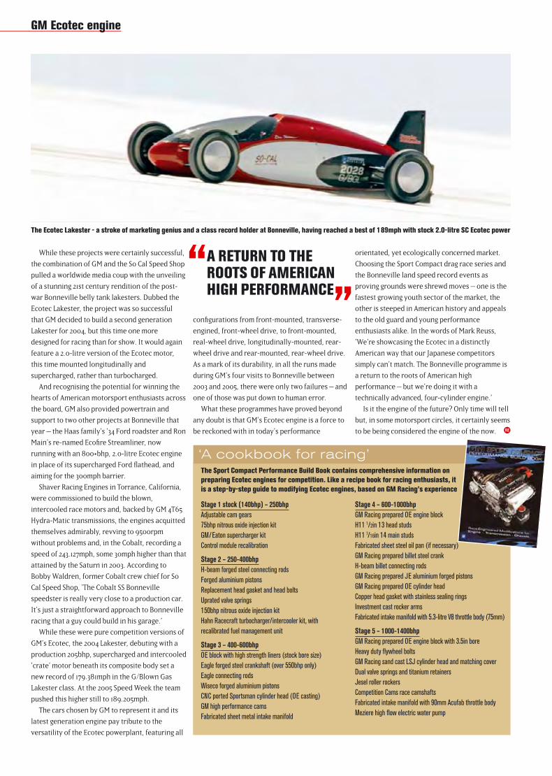
While these projects were certainly successful,
the combination of GM and the So Cal Speed Shop
pulled a worldwide media coup with the unveiling
of a stunning 21st century rendition of the post-
war Bonneville belly tank lakesters. Dubbed the
Ecotec Lakester, the project was so successful
that GM decided to build a second generation
Lakester for 2004, but this time one more
designed for racing than for show. It would again
feature a 2.0-litre version of the Ecotec motor,
this time mounted longitudinally and
supercharged, rather than turbocharged.
And recognising the potential for winning the
hearts of American motorsport enthusiasts across
the board, GM also provided powertrain and
support to two other projects at Bonneville that
year – the Haas family’s ‘34 Ford roadster and Ron
Main’s re-named Ecofi re Streamliner, now
running with an 800+bhp, 2.0-litre Ecotec engine
in place of its supercharged Ford fl athead, and
aiming for the 300mph barrier.
Shaver Racing Engines in Torrance, California,
were commissioned to build the blown,
intercooled race motors and, backed by GM 4T65
Hydra-Matic transmissions, the engines acquitted
themselves admirably, revving to 9500rpm
without problems and, in the Cobalt, recording a
speed of 243.127mph, some 30mph higher than that
attained by the Saturn in 2003. According to
Bobby Waldren, former Cobalt crew chief for So
Cal Speed Shop, ‘The Cobalt SS Bonneville
speedster is really very close to a production car.
It’s just a straightforward approach to Bonneville
racing that a guy could build in his garage.’
While these were pure competition versions of
GM’s Ecotec, the 2004 Lakester, debuting with a
production 205bhp, supercharged and intercooled
‘crate’ motor beneath its composite body set a
new record of 179.381mph in the G/Blown Gas
Lakester class. At the 2005 Speed Week the team
pushed this higher still to 189.205mph.
The cars chosen by GM to represent it and its
latest generation engine pay tribute to the
versatility of the Ecotec powerplant, featuring all
confi gurations from front-mounted, transverse-
engined, front-wheel drive, to front-mounted,
real-wheel drive, longitudinally-mounted, rear-
wheel drive and rear-mounted, rear-wheel drive.
As a mark of its durability, in all the runs made
during GM’s four visits to Bonneville between
2003 and 2005, there were only two failures – and
one of those was put down to human error.
What these programmes have proved beyond
any doubt is that GM’s Ecotec engine is a force to
be reckoned with in today’s performance
orientated, yet ecologically concerned market.
Choosing the Sport Compact drag race series and
the Bonneville land speed record events as
proving grounds were shrewd moves – one is the
fastest growing youth sector of the market, the
other is steeped in American history and appeals
to the old guard and young performance
enthusiasts alike. In the words of Mark Reuss,
‘We’re showcasing the Ecotec in a distinctly
American way that our Japanese competitors
simply can’t match. The Bonneville programme is
a return to the roots of American high
performance – but we’re doing it with a
technically advanced, four-cylinder engine.’
Is it the engine of the future? Only time will tell
but, in some motorsport circles, it certainly seems
to be being considered the engine of the now.
“ A RETURN TO THE ROOTS OF AMERICAN HIGH PERFORMANCE
”
Stage 1 stock (140bhp) – 250bhp
Adjustable cam gears
75bhp nitrous oxide injection kit
GM/Eaton supercharger kit
Control module recalibration
Stage 2 – 250-400bhp
H-beam forged steel connecting rods
Forged aluminium pistons
Replacement head gasket and head bolts
Uprated valve springs
150bhp nitrous oxide injection kit
Hahn Racecraft turbocharger/intercooler kit, with
recalibrated fuel management unit
Stage 3 – 400-600bhp
OE block with high strength liners (stock bore size)
Eagle forged steel crankshaft (over 550bhp only)
Eagle connecting rods
Wiseco forged aluminium pistons
CNC ported Sportsman cylinder head (OE casting)
GM high performance cams
Fabricated sheet metal intake manifold
RE
‘A cookbook for racing’The Sport Compact Performance Build Book contains comprehensive information on
preparing Ecotec engines for competition. Like a recipe book for racing enthusiasts, it
is a step-by-step guide to modifying Ecotec engines, based on GM Racing’s experience
Stage 4 – 600-1000bhp
GM Racing prepared OE engine block
H11 1/2in 13 head studs
H11 7/16in 14 main studs
Fabricated sheet steel oil pan (if necessary)
GM Racing prepared billet steel crank
H-beam billet connecting rods
GM Racing prepared JE aluminium forged pistons
GM Racing prepared OE cylinder head
Copper head gasket with stainless sealing rings
Investment cast rocker arms
Fabricated intake manifold with 5.3-litre V8 throttle body (75mm)
Stage 5 – 1000-1400bhp
GM Racing prepared OE engine block with 3.5in bore
Heavy duty fl ywheel bolts
GM Racing sand cast LSJ cylinder head and matching cover
Dual valve springs and titanium retainers
Jesel roller rockers
Competition Cams race camshafts
Fabricated intake manifold with 90mm Acufab throttle body
Meziere high fl ow electric water pump
The Ecotec Lakester - a stroke of marketing genius and a class record holder at Bonneville, having reached a best of 189mph with stock 2.0-litre SC Ecotec power
GM Ecotec engine
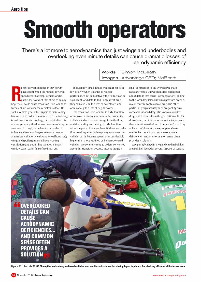
November 2005 Racecar Engineering54 www.racecar-engineering.com
Smooth operatorsThere’s a lot more to aerodynamics than just wings and underbodies and
overlooking even minute details can cause dramatic losses of aerodynamic effi ciency
Words Simon McBeath
Images Advantage CFD; McBeath
Recent correspondence in our ‘Forum’
pages spotlighted the human-powered
speed record attempt vehicle, and in
particular how dust that sticks to an oily
fi ngerprint could cause transition from lamina to
turbulent airfl ow over the vehicle’s surface. On
such a vehicle great effort is paid to maintaining
lamina fl ow in order to minimise skin friction drag
(also known as viscous drag), but details like this
are not generally the dominant sources of drag on
a racecar. In rough, though not strict order of
infl uence, the major drag sources on a racecar
are: its basic shape; wheels (and wheel housings);
wings and spoilers; internal fl ows (cooling,
ventilation) and details like handles, mirrors,
window seals, panel fi t, surface fi nish etc.
Individually, small details would appear to be
low priority when it comes to racecar
performance but cumulatively their effect can be
signifi cant. And details don’t only affect drag –
they can also lead to a loss of downforce, and
occasionally to a loss of engine power...
The transition from laminar to turbulent fl ow
occurs over distance as viscous effects near the
vehicle’s surface remove energy from the fl ow,
and the swirling and mixing of turbulent fl ow
takes the place of laminar fl ow. With racecars the
fl ow usually goes turbulent pretty soon over the
vehicle, partly because speeds are considerably
higher than those attained by human-powered
vehicles. We generally tend to be less concerned
about this transition because viscous drag is a
small contributor to the overall drag that a
racecar creates. But we should be concerned
about details that cause fl ow separations, adding
to the form drag (also known as pressure drag), a
major contributor to overall drag. The other
particularly signifi cant type of drag acting on a
racecar is induced drag, also known as vortex
drag, which results from the generation of lift (or
downforce), but this is more about set-up choice
than attention to the kind of details we’re looking
at here. Let’s look at some examples where
overlooked details can cause aerodynamic
defi ciencies, and where common sense often
provides a solution.
A paper published in 1963 and cited in Milliken
and Milliken looked at several aspects of surface
Figure 11: the Lola B1/00 ChampCar had a nicely radiused radiator inlet duct insert – shown here being taped in place – for blanking off some of the intake area
“ OVERLOOKED DETAILS CAN CAUSE AERODYNAMIC DEFICIENCIES... AND COMMON SENSE OFTEN PROVIDES A SOLUTION
”
Aero tips
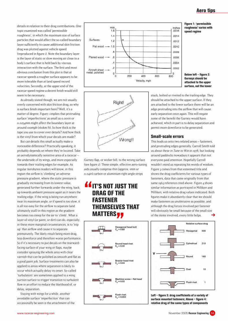
55November 2005 Racecar Engineeringwww.racecar-engineering.com
details in relation to their drag contributions. One
topic examined was called ‘permissible
roughness’, in which the maximum size of surface
particles that would affect the so-called boundary
layer suffi ciently to cause additional skin friction
drag was plotted against vehicle speed
(reproduced in fi gure 1). Note the boundary layer
is the layer of static or slow moving air close to a
body’s surface that is held back by viscous
interaction with the surface. The fi rst and most
obvious conclusion from this plot is that at
racecar speeds a rougher surface appears to be
more tolerable than at land speed record
velocities. Secondly, at the upper end of the
racecar speed regime a decent fi nish would still
seem to be necessary.
As already stated though, we are not usually
overly concerned with skin friction drag, so why
is surface fi nish important here? Well, it’s a
matter of degree. Figure 1 implies that protruding
surface ‘imperfections’ as small as 0.001in or
0.0254mm might affect the boundary layer at
around 100mph (160km/h). So how thick is the
tape you use to cover over details? And how thick
is the vinyl from which your decals are made?
But can details this small actually make a
noticeable difference? Practically speaking, it
probably depends on where they’re located. Take
an aerodynamically sensitive area of a racecar –
the underside of its wings, and more especially
towards their trailing edges for example. As
regular Aerobytes readers will know, in this
region the airfl ow is ‘climbing’ an adverse
pressure gradient, where the static pressure is
gradually increasing from its lowest value,
generated further forwards under the wing, back
up towards ambient pressure again as it nears the
trailing edge. If the wing is being run anywhere
near its maximum angle, or if speed is too slow, it
is all too easy for the airfl ow to separate (and
ultimately stall) in this region as the gradient
becomes too steep for the air to ‘climb’. What a
layer of vinyl (or paint, or dirt) can do, especially
in these more marginal circumstances, is to ‘trip
up’ that airfl ow and cause it to separate
prematurely. The likely result being more drag,
less downforce and therefore worse performance.
So if it’s necessary to put decals on the rearward-
facing surface of your wing or fl aps, maybe
consider spraying the whole area with clear
varnish that can be polished as smooth and fl at as
a good paint job. Surface treatments can also be
applied to areas where separation is likely to
occur which actually delay its onset. So-called
‘turbulators’ are sometimes applied to a wing
suction surface to trigger transition to turbulent
fl ow in an effort to reduce the likelihood of, or
delay, separation.
Staying with wings for a while, another
avoidable surface ‘imperfection’ that can
occasionally be seen is the attachment of the
Gurney fl ap, or wicker bill, to the wrong surface
(see fi gure 2). These simple, effective aero-tuning
aids usually comprise thin (approx. 1mm or
0.04in) carbon or aluminium right angle strips
Figure 1: ‘permissible
roughness’ varies with
speed regime
stuck, bolted or riveted to the trailing edge. They
should be attached to the upper surface. If they
are attached to the lower surface there will be an
edge protruding into the airfl ow that will cause
early separation once again. This will negate
some of the benefi t the Gurney would have
achieved, which in part is to delay separation and
permit more downforce to be generated.
Small-scale errorsThis leads us onto two related areas – fasteners,
and protruding edges generally. Carroll Smith told
us about these in Tune to Win in 1978, but looking
around paddocks nowadays it appears that not
everyone paid attention. Hopefully Carroll
wouldn’t mind us repeating his words of wisdom.
Figure 3 comes from that esteemed title and
shows the drag coeffi cients for various types of
fasteners, data that came originally from that
same 1963 reference cited above. Figure 4 shows
similar information as portrayed in Milliken and
Milliken, with relative drag values indicated. Both
fi gures make it abundantly clear that we should
make fasteners as unobtrusive as possible, and
although the drag forces involved per fastener
will obviously be small because of the small size
of the items involved, every little helps.
“ IT’S NOT JUST THE DRAG OF THE FASTENER THEMSELVES THAT MATTERS
”
Below left – fi gure 2:
Gurneys should be
attached to the upper
surface, not the lower
Left – fi gure 3: drag coeffi cients of a variety of
surface mounted fasteners; Above – fi gure 4:
relative drag of the same types of components
➔
Aero tips
Hexagonal head boltCD = 0.80
Round head rivetCD = 0.32
Brazier head rivetCD = 0.04
Machine screw – fl at headCD = 0.02
Flush rivetCD = 0.002
Hexagonal 400
Relative surface drag
Cylindrical 210
Round 160
Oval 10
Flush rivet 1
V
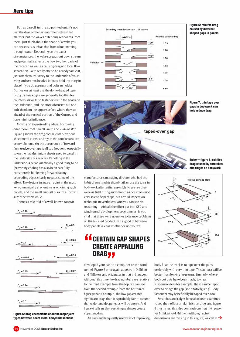
November 2005 Racecar Engineering56 www.racecar-engineering.com
But, as Carroll Smith also pointed out, it’s not
just the drag of the fastener themselves that
matters, but the wakes extending rearwards from
them. Just think about the shape of a wake you
can see easily, such as that from a boat moving
through water. Depending on the exact
circumstances, the wake spreads out downstream
and potentially affects the fl ow to other parts of
the racecar, as well as causing drag and local fl ow
separation. So to really offend an aerodynamicist,
just attach your Gurney to the underside of your
wing and use hex headed bolts to hold the thing in
place! If you do use nuts and bolts to hold a
Gurney on, at least use the dome-headed type
(wing trailing edges are generally too thin for
countersunk or fl ush fasteners) with the heads on
the underside, and the more obtrusive nut and
bolt shank on the upper surface where they sit
ahead of the vertical portion of the Gurney and
have minimal infl uence.
Moving on to protruding edges, borrowing
once more from Carroll Smith and Tune to Win.
Figure 5 shows the drag coeffi cients of various
sheet metal joints, and again the conclusions are
pretty obvious. Yet the occurrence of forward
facing edge overlaps is all too frequent, especially
so on the fl at aluminium sheets used to panel in
the underside of racecars. Panelling in the
underside is aerodynamically a good thing to do
(providing cooling has also been carefully
considered), but leaving forward facing
protruding edges clearly negates some of the
effort. The designs in fi gure 5 point at the most
aerodynamically effi cient ways of joining such
panels, and the small amount of extra effort will
surely be worthwhile.
There’s a tale told of a well-known racecar
developed your car on a computer or in a wind
tunnel. Figure 6 once again appears in Milliken
and Milliken, and originates in that 1963 paper.
Although this time the drag numbers are relative
to the third example from the top, we can see
from the second example from the bottom of
fi gure 5 that if a simple, shallow gap creates
signifi cant drag, then it is probably fair to assume
that wider and deeper gaps will be worse. And
fi gure 6 tells us that certain gap shapes create
appalling drag.
An easy and frequently used way of improving
body fi t at the track is to tape over the joins,
preferably with very thin tape. This at least will be
better than leaving large gaps. Similarly, where
body cut outs have been made, to clear
suspension legs for example, these can be taped
over to bridge the gap (see photo fi gure 7). Body
fasteners may benefi cially be taped over, too.
Scratches and ridges have also been examined
to see their effect on skin friction drag, and fi gure
8 illustrates, this also coming from that 1963 paper
via Milliken and Milliken. Although actual
dimensions are missing in this fi gure, we can at Figure 5: drag coeffi cients of all the major joint
types between sheet metal bodywork sections
Figure 6: relative drag
caused by different
shaped gaps in panels
Figure 7: thin tape over
gaps in bodywork can
help reduce drag
Below – fi gure 8: relative
drag caused by scratches
and ridges on bodywork
manufacturer’s managing director who had the
habit of running his thumbnail across the joins in
bodywork after initial assembly to ensure they
were as tight fi tting and smooth as possible – not
very scientifi c perhaps, but a valid inspection
technique nevertheless. And you can see his
reasoning – with all the effort put into CFD and
wind tunnel development programmes, it was
vital that there were no major tolerance problems
on the fi nished product. But a good fi t between
body panels is vital whether or not you’ve
“ CERTAIN GAP SHAPES CREATE APPALLING DRAG
”
➔
Aero tips
Boundary layer thickness = .307 inches
Velocity
Relative surface drag
1.39
1.20
1.00
1.62
1.17
1.28
6.66
.190”
.22”
.22”
.275”
–5°
–1° –7°
–10° +5°
–2°
CD = 0.70
CD = 0.70
CD = 0.11
CD = –0.04
CD = 0.13
CD = 0.24
CD = 0.01
CD = 0.5
CD = 0.24
CD = 0.16
CD = 0.07
Relative surface drag
V
V
V
1
h
80
130
h = b
h = 1/2b
h
h
h = b
b
b
b
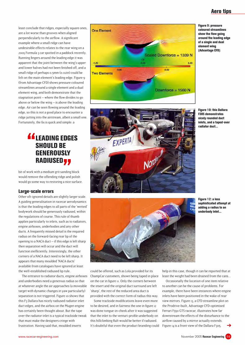
59November 2005 Racecar Engineeringwww.racecar-engineering.com
least conclude that ridges, especially square ones,
are a lot worse than grooves when aligned
perpendicularly to the airfl ow. A signifi cant
example where a small ridge can have
undesirable effects relates to the rear wing on a
2005 Formula 3 car spotted in a paddock recently.
Running fi ngers around the leading edge it was
apparent that the joint between the wing’s upper
and lower halves had not been fi nished off, and a
small ridge of perhaps 0.5mm (0.02in) could be
felt on the main element’s leading edge. Figure 9
(from Advantage CFD) shows pressure coloured
streamlines around a single element and a dual
element wing, and both demonstrate that the
stagnation point – where the fl ow divides to go
above or below the wing – is above the leading
edge. Air can be seen fl owing around the leading
edge, so this is not a good place to encounter a
ridge jutting into the airstream, albeit a small one.
Fortunately, the fi x is quick and simple: a
could be offered, such as Lola provided for its
ChampCar customers, shown being taped in place
on the car in fi gure 11. Only the corners between
the insert and the original duct surround are left
‘sharp’, the rest of the reduced area duct is
provided with the correct form of radius this way.
Some trackside modifi cations leave even more
to be desired, and in fairness the one in fi gure 12
was done tongue-in-cheek after it was suggested
that the inlet to the venturi-profi le underbody on
this hillclimbing Ralt would be better if radiused.
It’s doubtful that even the product branding could
help in this case, though it can be reported that at
least the weight had been drained from the cans...
Occasionally the location of one item relative
to another can be the cause of problems. For
example, there have been instances where engine
inlets have been positioned in the wake of rear
view mirrors. Figure 13, a CFD streamline plot on
the Prodrive-built, Advantage CFD-optimised
Ferrari F550 GTS racecar, illustrates how far
downstream the effects of the disturbance to the
airfl ow caused by a mirror actually extends.
Figure 14 is a front view of the Dallara F305,
bit of work with a medium grit sanding block
would remove the offending ridge and polish
would go some way to restoring a nice surface.
Large-scale errorsOther oft-ignored details are slightly larger scale.
A guiding generalisation in racecar aerodynamics
is that the leading edges to all parts of the ‘wetted’
bodywork should be generously radiused, within
the regulations of course. This rule of thumb
applies particularly to inlets, such as to radiators,
engine airboxes, underbodies and any other
ducts. A frequently missed detail is the required
radius on the forward-facing rear lip of the
opening to a NACA duct – if this edge is left sharp
then separation will occur and the duct will
function ineffi ciently. Interestingly, the other
corners of a NACA duct need to be left sharp. It
appears that many moulded ‘NACA ducts’
available from catalogues have ignored at least
the well-established radiused lip rule.
The entrance to radiator ducts, engine airboxes
and underbodies need a generous radius so that
at whatever angle the air approaches (a moveable
target with dynamic changes in yaw particularly)
separation is not triggered. Figure 10 shows that
this F3 Dallara has nicely radiused radiator inlet
duct edges, and the airbox on the Mugen engine
has certainly been thought about. But the tape
over the radiator inlet is a typical trackside tweak
that must make the designers cringe with
frustration. Having said that, moulded inserts
Figure 9: pressure
coloured streamlines
show the fl ow going
around the leading edge
of a single and dual
element wing
(Advantage CFD)
Figure 10: this Dallara
F305 demonstrates
nicely rounded duct
inlets, and a taped-over
radiator duct...
Figure 12: a less
sophisticated attempt at
adding a radius to an
underbody inlet...
➔
“ LEADING EDGES SHOULD BE GENEROUSLY RADIUSED
”
Aero tips
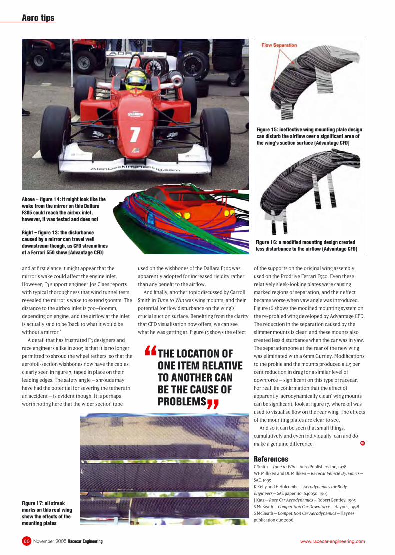
November 2005 Racecar Engineering60 www.racecar-engineering.com
and at fi rst glance it might appear that the
mirror’s wake could affect the engine inlet.
However, F3 support engineer Jos Claes reports
with typical thoroughness that wind tunnel tests
revealed the mirror’s wake to extend 500mm. The
distance to the airbox inlet is 700–800mm,
depending on engine, and the airfl ow at the inlet
is actually said to be ‘back to what it would be
without a mirror.’
A detail that has frustrated F3 designers and
race engineers alike in 2005 is that it is no longer
permitted to shroud the wheel tethers, so that the
aerofoil-section wishbones now have the cables,
clearly seen in fi gure 7, taped in place on their
leading edges. The safety angle – shrouds may
have had the potential for severing the tethers in
an accident – is evident though. It is perhaps
worth noting here that the wider section tube
of the supports on the original wing assembly
used on the Prodrive Ferrari F550. Even these
relatively sleek-looking plates were causing
marked regions of separation, and their effect
became worse when yaw angle was introduced.
Figure 16 shows the modifi ed mounting system on
the re-profi led wing developed by Advantage CFD.
The reduction in the separation caused by the
slimmer mounts is clear, and these mounts also
created less disturbance when the car was in yaw.
The separation zone at the rear of the new wing
was eliminated with a 6mm Gurney. Modifi cations
to the profi le and the mounts produced a 2.5 per
cent reduction in drag for a similar level of
downforce – signifi cant on this type of racecar.
For real life confi rmation that the effect of
apparently ‘aerodynamically clean’ wing mounts
can be signifi cant, look at fi gure 17, where oil was
used to visualise fl ow on the rear wing. The effects
of the mounting plates are clear to see.
And so it can be seen that small things,
cumulatively and even individually, can and do
make a genuine difference.
ReferencesC Smith – Tune to Win – Aero Publishers Inc, 1978
WF Milliken and DL Milliken – Racecar Vehicle Dynamics –
SAE, 1995
K Kelly and H Holcombe – Aerodynamics for Body
Engineers – SAE paper no. 640050, 1963
J Katz – Race Car Aerodynamics – Robert Bentley, 1995
S McBeath – Competition Car Downforce – Haynes, 1998
S McBeath – Competition Car Aerodynamics – Haynes,
publication due 2006
used on the wishbones of the Dallara F305 was
apparently adopted for increased rigidity rather
than any benefi t to the airfl ow.
And fi nally, another topic discussed by Carroll
Smith in Tune to Win was wing mounts, and their
potential for fl ow disturbance on the wing’s
crucial suction surface. Benefi ting from the clarity
that CFD visualisation now offers, we can see
what he was getting at. Figure 15 shows the effect
Figure 16: a modifi ed mounting design created
less disturbance to the airfl ow (Advantage CFD)
“ THE LOCATION OF ONE ITEM RELATIVE TO ANOTHER CAN BE THE CAUSE OF PROBLEMS
”
Above – fi gure 14: it might look like the
wake from the mirror on this Dallara
F305 could reach the airbox inlet,
however, it was tested and does not
Right – fi gure 13: the disturbance
caused by a mirror can travel well
downstream though, as CFD streamlines
of a Ferrari 550 show (Advantage CFD)
Figure 17: oil streak
marks on this real wing
show the effects of the
mounting plates
Figure 15: ineffective wing mounting plate design
can disturb the airfl ow over a signifi cant area of
the wing’s suction surface (Advantage CFD)
RE
Aero tips
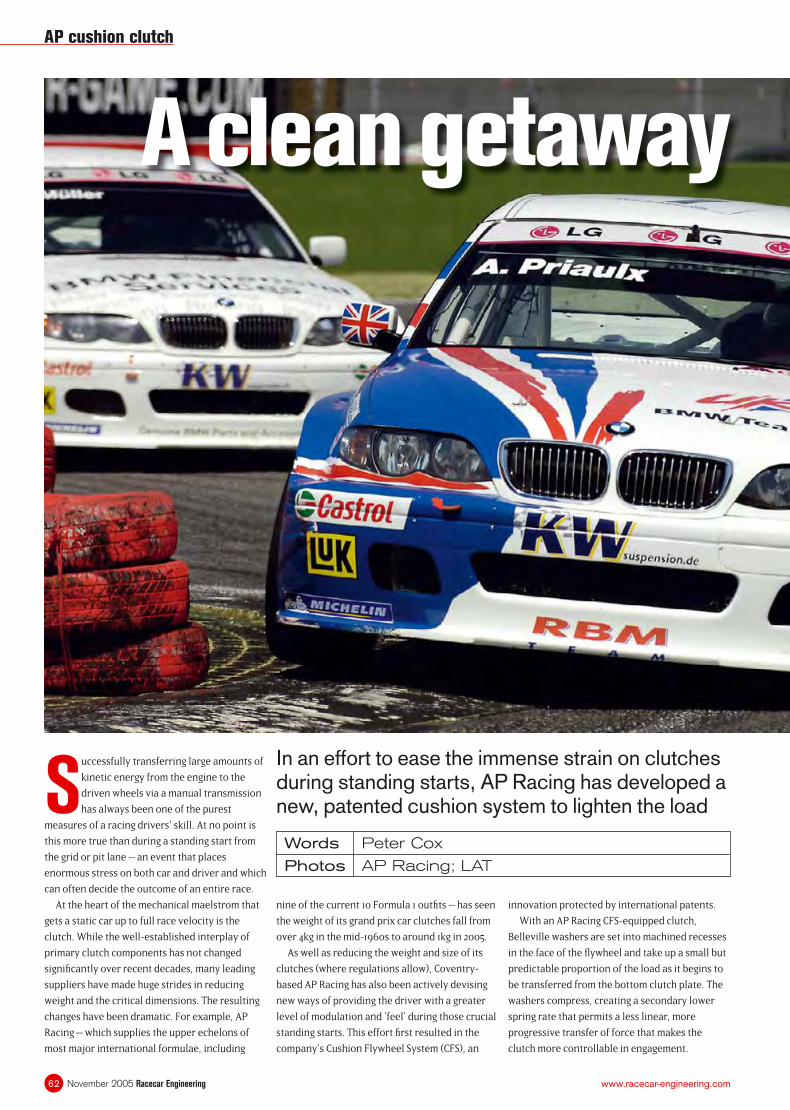
November 2005 Racecar Engineering62 www.racecar-engineering.com
In an effort to ease the immense strain on clutches during standing starts, AP Racing has developed a new, patented cushion system to lighten the load
Words Peter Cox
Photos AP Racing; LAT
Successfully transferring large amounts of
kinetic energy from the engine to the
driven wheels via a manual transmission
has always been one of the purest
measures of a racing drivers’ skill. At no point is
this more true than during a standing start from
the grid or pit lane – an event that places
enormous stress on both car and driver and which
can often decide the outcome of an entire race.
At the heart of the mechanical maelstrom that
gets a static car up to full race velocity is the
clutch. While the well-established interplay of
primary clutch components has not changed
signifi cantly over recent decades, many leading
suppliers have made huge strides in reducing
weight and the critical dimensions. The resulting
changes have been dramatic. For example, AP
Racing – which supplies the upper echelons of
most major international formulae, including
nine of the current 10 Formula 1 outfi ts – has seen
the weight of its grand prix car clutches fall from
over 4kg in the mid-1960s to around 1kg in 2005.
As well as reducing the weight and size of its
clutches (where regulations allow), Coventry-
based AP Racing has also been actively devising
new ways of providing the driver with a greater
level of modulation and ‘feel’ during those crucial
standing starts. This effort fi rst resulted in the
company’s Cushion Flywheel System (CFS), an
innovation protected by international patents.
With an AP Racing CFS-equipped clutch,
Belleville washers are set into machined recesses
in the face of the fl ywheel and take up a small but
predictable proportion of the load as it begins to
be transferred from the bottom clutch plate. The
washers compress, creating a secondary lower
spring rate that permits a less linear, more
progressive transfer of force that makes the
clutch more controllable in engagement.
AP cushion clutch
A clean getaway
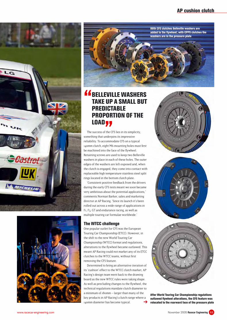
63November 2005 Racecar Engineeringwww.racecar-engineering.com
The success of the CFS lies in its simplicity,
something that underpins its impressive
reliability. To accommodate CFS on a typical
140mm clutch, eight M6 mounting holes must fi rst
be machined into the face of the fl ywheel.
Retaining screws are used to keep two Belleville
washers in place in each of these holes. The outer
edges of the washers are left exposed and, when
the clutch is engaged, they come into contact with
replaceable high temperature stainless steel split
rings located in the bottom clutch plate.
‘Consistent positive feedback from the drivers
during the early CFS tests meant we soon became
very ambitious about the potential applications,’
comments Norman Barker, sales and marketing
director at AP Racing. ‘Since its launch it’s been
rolled out across a wide range of applications in
F1, F3, GT and endurance racing, as well as
multiple touring car formulae worldwide.’
The WTCC challengeOne popular outlet for CFS was the European
Touring Car Championship (ETCC). However, in
the shift to the new World Touring Car
Championship (WTCC) format and regulations,
alterations to the fl ywheel became outlawed. This
meant AP Racing could not market any of its ETCC
clutches to the WTCC teams, without fi rst
removing the CFS feature.
Determined to bring an alternative iteration of
its ‘cushion’ effect to the WTCC clutch market, AP
Racing’s design team went back to the drawing
board as the new WTCC rules were taking shape.
As well as precluding changes to the fl ywheel, the
technical regulations mandate clutch diameter to
a minimum of 180mm – larger than many of the
key products in AP Racing’s clutch range where a
140mm diameter has become typical.
“ BELLEVILLE WASHERS TAKE UP A SMALL BUT PREDICTABLE PROPORTION OF THE LOAD
”
After World Touring Car Championship regulations
outlawed fl ywheel alterations, the CFS feature was
relocated to the rearward face of the pressure plate
With CFS clutches Belleville washers are
added to the fl ywheel; with CPPS clutches the
washers are in the pressure plate
➔
AP cushion clutch
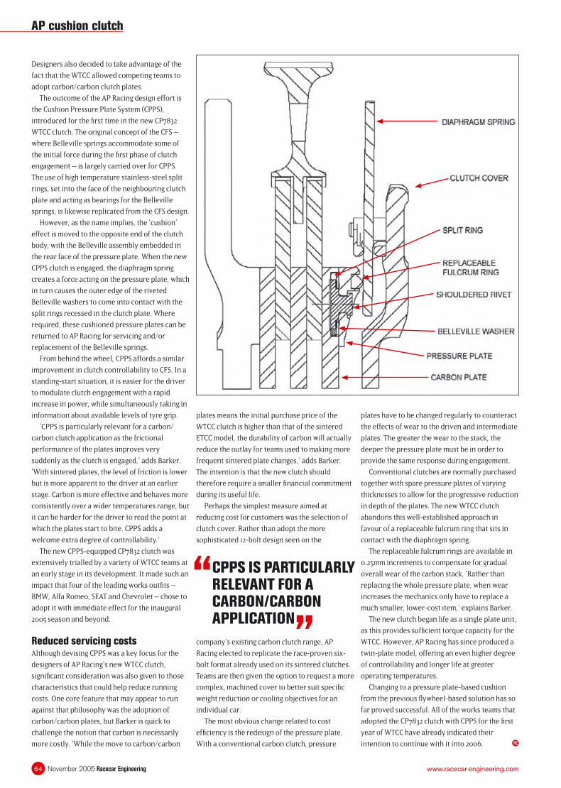
November 2005 Racecar Engineering64 www.racecar-engineering.com
Designers also decided to take advantage of the
fact that the WTCC allowed competing teams to
adopt carbon/carbon clutch plates.
The outcome of the AP Racing design effort is
the Cushion Pressure Plate System (CPPS),
introduced for the fi rst time in the new CP7832
WTCC clutch. The original concept of the CFS –
where Belleville springs accommodate some of
the initial force during the fi rst phase of clutch
engagement – is largely carried over for CPPS.
The use of high temperature stainless-steel split
rings, set into the face of the neighbouring clutch
plate and acting as bearings for the Belleville
springs, is likewise replicated from the CFS design.
However, as the name implies, the ‘cushion’
effect is moved to the opposite end of the clutch
body, with the Belleville assembly embedded in
the rear face of the pressure plate. When the new
CPPS clutch is engaged, the diaphragm spring
creates a force acting on the pressure plate, which
in turn causes the outer edge of the riveted
Belleville washers to come into contact with the
split rings recessed in the clutch plate. Where
required, these cushioned pressure plates can be
returned to AP Racing for servicing and/or
replacement of the Belleville springs.
From behind the wheel, CPPS affords a similar
improvement in clutch controllability to CFS. In a
standing-start situation, it is easier for the driver
to modulate clutch engagement with a rapid
increase in power, while simultaneously taking in
information about available levels of tyre grip.
‘CPPS is particularly relevant for a carbon/
carbon clutch application as the frictional
performance of the plates improves very
suddenly as the clutch is engaged,’ adds Barker.
‘With sintered plates, the level of friction is lower
but is more apparent to the driver at an earlier
stage. Carbon is more effective and behaves more
consistently over a wider temperatures range, but
it can be harder for the driver to read the point at
which the plates start to bite. CPPS adds a
welcome extra degree of controllability.’
The new CPPS-equipped CP7832 clutch was
extensively trialled by a variety of WTCC teams at
an early stage in its development. It made such an
impact that four of the leading works outfi ts –
BMW, Alfa Romeo, SEAT and Chevrolet – chose to
adopt it with immediate effect for the inaugural
2005 season and beyond.
Reduced servicing costsAlthough devising CPPS was a key focus for the
designers of AP Racing’s new WTCC clutch,
signifi cant consideration was also given to those
characteristics that could help reduce running
costs. One core feature that may appear to run
against that philosophy was the adoption of
carbon/carbon plates, but Barker is quick to
challenge the notion that carbon is necessarily
more costly. ‘While the move to carbon/carbon
plates means the initial purchase price of the
WTCC clutch is higher than that of the sintered
ETCC model, the durability of carbon will actually
reduce the outlay for teams used to making more
frequent sintered plate changes,’ adds Barker.
The intention is that the new clutch should
therefore require a smaller fi nancial commitment
during its useful life.
Perhaps the simplest measure aimed at
reducing cost for customers was the selection of
clutch cover. Rather than adopt the more
sophisticated 12-bolt design seen on the
plates have to be changed regularly to counteract
the effects of wear to the driven and intermediate
plates. The greater the wear to the stack, the
deeper the pressure plate must be in order to
provide the same response during engagement.
Conventional clutches are normally purchased
together with spare pressure plates of varying
thicknesses to allow for the progressive reduction
in depth of the plates. The new WTCC clutch
abandons this well-established approach in
favour of a replaceable fulcrum ring that sits in
contact with the diaphragm spring.
The replaceable fulcrum rings are available in
0.25mm increments to compensate for gradual
overall wear of the carbon stack. ‘Rather than
replacing the whole pressure plate, when wear
increases the mechanics only have to replace a
much smaller, lower-cost item,’ explains Barker.
The new clutch began life as a single plate unit,
as this provides suffi cient torque capacity for the
WTCC. However, AP Racing has since produced a
twin-plate model, offering an even higher degree
of controllability and longer life at greater
operating temperatures.
Changing to a pressure plate-based cushion
from the previous fl ywheel-based solution has so
far proved successful. All of the works teams that
adopted the CP7832 clutch with CPPS for the fi rst
year of WTCC have already indicated their
intention to continue with it into 2006.
“ CPPS IS PARTICULARLY RELEVANT FOR A CARBON/CARBON APPLICATION
”company’s existing carbon clutch range, AP
Racing elected to replicate the race-proven six-
bolt format already used on its sintered clutches.
Teams are then given the option to request a more
complex, machined cover to better suit specifi c
weight reduction or cooling objectives for an
individual car.
The most obvious change related to cost
effi ciency is the redesign of the pressure plate.
With a conventional carbon clutch, pressure RE
AP cushion clutch
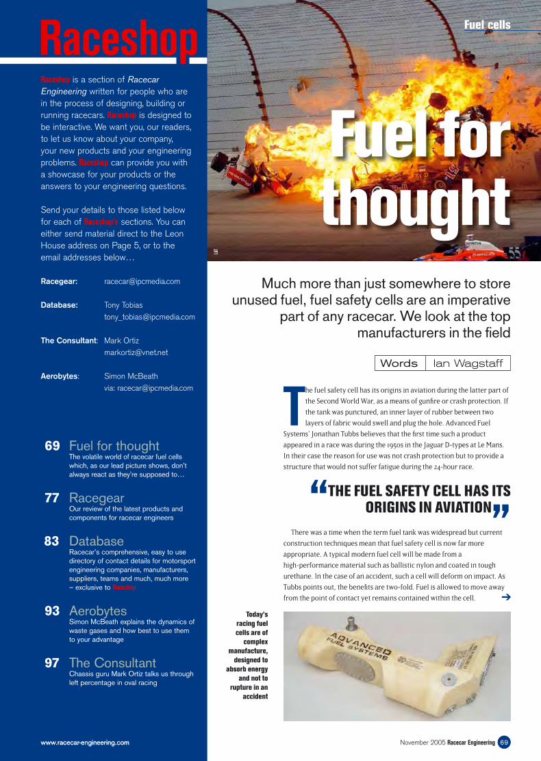
Much more than just somewhere to store unused fuel, fuel safety cells are an imperative
part of any racecar. We look at the top manufacturers in the fi eld
Words Ian Wagstaff
69www.racecar-engineering.com
The fuel safety cell has its origins in aviation during the latter part of
the Second World War, as a means of gunfi re or crash protection. If
the tank was punctured, an inner layer of rubber between two
layers of fabric would swell and plug the hole. Advanced Fuel
Systems’ Jonathan Tubbs believes that the fi rst time such a product
appeared in a race was during the 1950s in the Jaguar D-types at Le Mans.
In their case the reason for use was not crash protection but to provide a
structure that would not suffer fatigue during the 24-hour race.
RaceshopRaceshop is a section of Racecar Engineering written for people who are in the process of designing, building or running racecars. Raceshop is designed to be interactive. We want you, our readers, to let us know about your company, your new products and your engineering problems. Raceshop can provide you with a showcase for your products or the answers to your engineering questions.
Send your details to those listed below for each of Raceshop’s sections. You can either send material direct to the Leon House address on Page 5, or to the email addresses below…
Racegear: [email protected]
Database: Tony Tobias [email protected]
The Consultant: Mark Ortiz [email protected]
Aerobytes: Simon McBeath via: [email protected]
69 Fuel for thoughtThe volatile world of racecar fuel cells which, as our lead picture shows, don’t always react as they’re supposed to…
77 RacegearOur review of the latest products and components for racecar engineers
83 DatabaseRacecar’s comprehensive, easy to use directory of contact details for motorsport engineering companies, manufacturers, suppliers, teams and much, much more – exclusive to Raceshop
93 AerobytesSimon McBeath explains the dynamics of waste gases and how best to use them to your advantage
97 The ConsultantChassis guru Mark Ortiz talks us through left percentage in oval racing
Today’s
racing fuel
cells are of
complex
manufacture,
designed to
absorb energy
and not to
rupture in an
accident
“THE FUEL SAFETY CELL HAS ITS ORIGINS IN AVIATION
”There was a time when the term fuel tank was widespread but current
construction techniques mean that fuel safety cell is now far more
appropriate. A typical modern fuel cell will be made from a
high-performance material such as ballistic nylon and coated in tough
urethane. In the case of an accident, such a cell will deform on impact. As
Tubbs points out, the benefi ts are two-fold. Fuel is allowed to move away
from the point of contact yet remains contained within the cell. ➔
Fuel cells
69November 2005 Racecar Engineeringwww.racecar-engineering.com
LAT
Fuel for thought
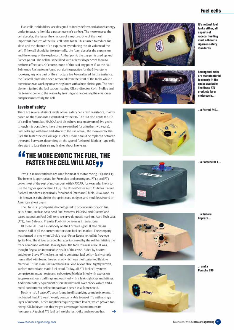
Two FIA main standards are used for most of motor racing, FT5 and FT3.
The former is appropriate for Formula 1 and prototypes. FT3.5 and FT3
cover most of the rest of motorsport with NASCAR, for example, likely to
use the higher specifi cation FT3.5. The United States Auto Club has its own
fuel cell standards specifi cally for alcohol (methanol) fuels. USAC 1000, as
it is known, is suitable for the sprint cars, midgets and modifi eds found on
America’s short ovals.
The FIA lists 13 companies homologated to produce motorsport fuel
cells. Some, such as Advanced Fuel Systems, PRONAL and Queensland-
based Australian Fuel Cell, tend to serve domestic markets. Aero Tech Labs
(ATL), Fuel Safe and Premier Fuel can be seen as international.
Of these, ATL has a monopoly on the Formula 1 grid. It also claims
around half of all the current motorsport fuel cell market. The company
was formed in 1971 when US club racer Peter Regna rolled his frog-eye
Sprite Mk1. The driver escaped but sparks caused by the roll bar hitting the
track combined with fuel leaking from the tank to cause a fi re. It was,
thought Regna, an inexcusable result of the crash. Aided by his fi rst
employee, Steve White, he started to construct fuel cells – fairly simple
items fi lled with foam, the secret of which was their patented fl exible
material. This is manufactured from Du Pont Kevlar fi bre, tightly woven,
surface treated and made fuel proof. Today, all ATL fuel cell systems
comprise an impact resistant, rubberised bladder fi lled with explosion
suppressant foam baffl ings and outfi tted with a leak-tight cap and fi ttings.
Additional safety equipment often includes roll-over check valves and a
metal container to defl ect impacts and serve as a fl ame shield.
Despite its US base ATL soon found itself supplying grand prix teams. It
is claimed that ATL was the only company able to meet FT5 with a single
layer of material, other suppliers requiring three layers, which proved too
heavy. ATL believes it is this weight advantage that maintains its
monopoly. A typical ATL fuel cell weighs just 5.6kg and not one has
Fuel cells
71November 2005 Racecar Engineeringwww.racecar-engineering.com
Fuel cells, or bladders, are designed to freely deform and absorb energy
under impact, rather like a passenger car’s air bag. The more energy the
cell absorbs, the lesser the chances of a rupture. One of the most
important features of the fuel cell is the foam. This is used to reduce fuel
slosh and the chance of an explosion by reducing the air volume of the
cell. If the cell should ignite internally, the foam absorbs the expansion
and the energy of the explosion. At that point, the oxygen is used up and
fl ames go out. The cell must be fi lled with at least 80 per cent foam to
perform effectively. Of course, none of this is of any point if, as the Paul
Belmondo Racing team found out during practice for the Silverstone
1000kms, any one part of the structure has been altered. In this instance,
the fuel cell plates had been removed from the front of the tanks while a
technician was working on a wiring loom with a heat shrink gun. The heat
element ignited the fuel vapour leaving ATL co-director Kevin Molloy and
his team to come to the rescue by treating and re-coating the elastomer
and pressure testing the cell.
Levels of safetyThere are several distinct levels of fuel safety cell crash resistance, mainly
based on the standards established by the FIA. The FIA also limits the life
of a cell in Formula 1, NASCAR and elsewhere to a maximum of fi ve years
(though it is possible to have them re-certifi ed for a further two years).
Fuel cells age with time and also with the use of fuel; the more exotic the
fuel, the faster the cell will age. Fuel cell foam should be replaced between
three and fi ve years depending on the type of fuel used. Bladder-type cells
also start to lose their strength after about fi ve years.
“ THE MORE EXOTIC THE FUEL, THE FASTER THE CELL WILL AGE
”
➔
It’s not just fuel
tanks either, all
aspects of
racecar fuelling
must adhere to
rigorous safety
standards
Racing fuel cells
are manufactured
to closely fi t the
space available
like these ATL
products for a
motorcycle...
...a Ferrari F40...
...a Porsche 911...
...a Subaru
Impreza...
... and a
Porsche 996
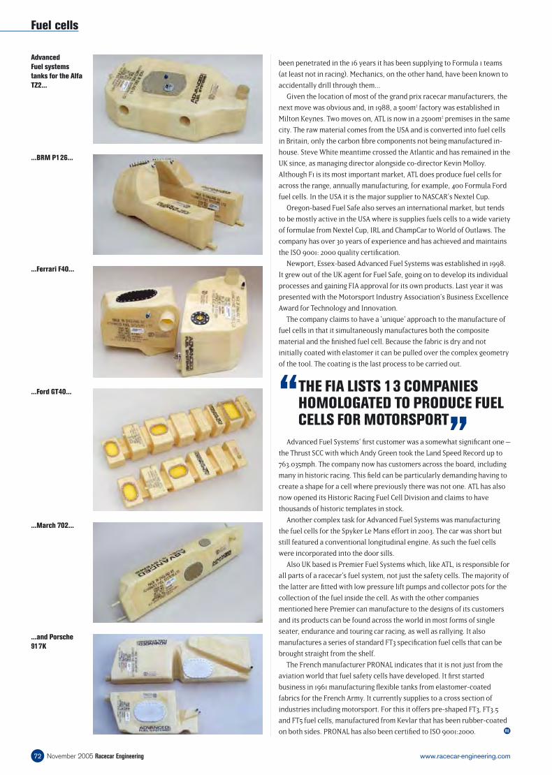
Advanced Fuel Systems’ fi rst customer was a somewhat signifi cant one –
the Thrust SCC with which Andy Green took the Land Speed Record up to
763.035mph. The company now has customers across the board, including
many in historic racing. This fi eld can be particularly demanding having to
create a shape for a cell where previously there was not one. ATL has also
now opened its Historic Racing Fuel Cell Division and claims to have
thousands of historic templates in stock.
Another complex task for Advanced Fuel Systems was manufacturing
the fuel cells for the Spyker Le Mans effort in 2003. The car was short but
still featured a conventional longitudinal engine. As such the fuel cells
were incorporated into the door sills.
Also UK based is Premier Fuel Systems which, like ATL, is responsible for
all parts of a racecar’s fuel system, not just the safety cells. The majority of
the latter are fi tted with low pressure lift pumps and collector pots for the
collection of the fuel inside the cell. As with the other companies
mentioned here Premier can manufacture to the designs of its customers
and its products can be found across the world in most forms of single
seater, endurance and touring car racing, as well as rallying. It also
manufactures a series of standard FT3 specifi cation fuel cells that can be
brought straight from the shelf.
The French manufacturer PRONAL indicates that it is not just from the
aviation world that fuel safety cells have developed. It fi rst started
business in 1961 manufacturing fl exible tanks from elastomer-coated
fabrics for the French Army. It currently supplies to a cross section of
industries including motorsport. For this it offers pre-shaped FT3, FT3.5
and FT5 fuel cells, manufactured from Kevlar that has been rubber-coated
on both sides. PRONAL has also been certifi ed to ISO 9001:2000.
Fuel cells
November 2005 Racecar Engineering72 www.racecar-engineering.com
RE
“ THE FIA LISTS 13 COMPANIES HOMOLOGATED TO PRODUCE FUEL CELLS FOR MOTORSPORT
”
been penetrated in the 16 years it has been supplying to Formula 1 teams
(at least not in racing). Mechanics, on the other hand, have been known to
accidentally drill through them...
Given the location of most of the grand prix racecar manufacturers, the
next move was obvious and, in 1988, a 500m2 factory was established in
Milton Keynes. Two moves on, ATL is now in a 2500m2 premises in the same
city. The raw material comes from the USA and is converted into fuel cells
in Britain, only the carbon fi bre components not being manufactured in-
house. Steve White meantime crossed the Atlantic and has remained in the
UK since, as managing director alongside co-director Kevin Molloy.
Although F1 is its most important market, ATL does produce fuel cells for
across the range, annually manufacturing, for example, 400 Formula Ford
fuel cells. In the USA it is the major supplier to NASCAR’s Nextel Cup.
Oregon-based Fuel Safe also serves an international market, but tends
to be mostly active in the USA where is supplies fuels cells to a wide variety
of formulae from Nextel Cup, IRL and ChampCar to World of Outlaws. The
company has over 30 years of experience and has achieved and maintains
the ISO 9001: 2000 quality certifi cation.
Newport, Essex-based Advanced Fuel Systems was established in 1998.
It grew out of the UK agent for Fuel Safe, going on to develop its individual
processes and gaining FIA approval for its own products. Last year it was
presented with the Motorsport Industry Association’s Business Excellence
Award for Technology and Innovation.
The company claims to have a ‘unique’ approach to the manufacture of
fuel cells in that it simultaneously manufactures both the composite
material and the fi nished fuel cell. Because the fabric is dry and not
initially coated with elastomer it can be pulled over the complex geometry
of the tool. The coating is the last process to be carried out.
Advanced
Fuel systems
tanks for the Alfa
TZ2...
...BRM P126...
...Ferrari F40...
...Ford GT40...
...March 702...
...and Porsche
917K
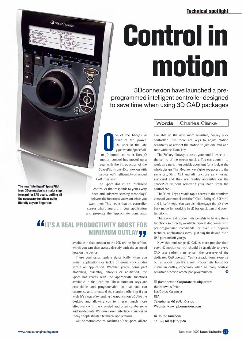
Technical spotlight
75www.racecar-engineering.com
Control in motion
Words Charles Clarke
75www.racecar-engineering.com
available on the new, more sensitive, hockey puck
controller. Plus there are keys to adjust motion
sensitivity or restrict the motion to just one axis at a
time with the ‘Dom’ key.
The ‘Fit’ key allows you to size your model or scene to
the centre of the screen quickly. You can zoom in to
work on a part, then quickly zoom out for a look at the
whole design. The ‘Modifier Keys’ give you access to the
same Esc, Shift, Ctrl and Alt functions as a normal
keyboard and they are readily accessible on the
SpacePilot without removing your hand from the
control cap.
The ‘View’ keys provide rapid access to the standard
views of your model with the T (Top), R (Right), F (Front)
and L (Left) keys. You can also disengage the 3D View
Lock mode for working in 2D for quick pan and zoom
functions.
There are real productivity benefi ts to having these
functions so directly available. SpacePilot comes with
pre-programmed commands for over 120 popular
technical applications so you just plug the device into a
USB port and off you go.
Now that mid-range 3D CAD is more popular than
ever, 3D motion control should be available to every
CAD user rather than remain the preserve of the
dedicated CAD operator. Yes it’s an additional expense
but at about £320 it’s a real productivity boost for
minimum outlay, especially when so many context
sensitive functions come pre-programmed.
3Dconnexion Corporate Headquarters
180 Knowles Drive
Los Gatos, CA 95032
USA
Telephone: +(1) 408.376.2500
Website: www.3dconnexion.com
In United Kingdom:
Tel. +44 (0) 1952 243629
“IT’S A REAL PRODUCTIVITY BOOST FOR MINIMUM OUTLAY
”
RE
November 2005 Racecar Engineering
available in that context to the LCD on the SpacePilot,
which you can then access directly with the 21 speed
keys on the device.
These commands update dynamically when you
switch applications or tackle different work modes
within an application. Whether you’re doing part
modelling, assembly, analysis or animation, the
SpacePilot reacts with the appropriate functions
available in that context. These function keys are
extendable and programmable so that you can
customise and/or extend the standard offerings if you
wish. It’s a way of extending the application’s GUI to the
desktop and allowing you to interact much more
effectively with the crowded and often cumbersome
and inadequate Windows user interface common in
today’s sophisticated technical applications.
All the motion control facilities of the SpaceBall are
3Dconnexion have launched a pre-programmed intelligent controller designed to save time when using 3D CAD packages
One of the badges of
offi ce of the ‘power’
CAD user in the late
1990s was the SpaceBall,
or 3D motion controller. Now 3D
motion control has moved up a
gear with the introduction of the
SpacePilot from 3Dconnexion with
its so-called ‘intelligent, two-handed
CAD interface’.
The SpacePilot is an intelligent
controller that responds to your every
need and ‘adaptive sensing technology’
delivers the functions you want when you
want them. This means that the controller
senses where you are in your application
and presents the appropriate commands
The new ‘intelligent’ SpacePilot
from 3Dconnexion is a major step
forward for CAD users, putting all
the necessary functions quite
literally at your fi ngertips

Pro latchUK-based latch designer and manufacturer Protex has created a new
economically priced latch to add to its extensive line of quick-action fasteners. The 47-2650 latch is compatible with a range of re-sealable fasteners found in commercial, agricultural and logistical applications.
The zinc-plated mild steel fastener, measuring 207mm long by 40mm wide, offers a 20mm grip range adjustment. A threaded draw bar
is built into the device, designed to withstand forces up to 1000kgf.The latch has been designed for use alongside the Protex type 04-
2650 catchplates. Lockable padlocks or purpose-designed sealing pins can also be used as protective devices.
For more information call +44 (0) 1527 63231 or visit www.protex-fasteners.com
77November 2005 Racecar Engineeringwww.racecar-engineering.com
R A C E G E A RNew products and services for racecar engineers
Belter of a pumpUS fuel system specialist, Barry Grant Inc, has redesigned its belt-drive fuel
pump for engines with high volume fuel demands, particularly those running on alcohol.
The BG belt-drive fuel pump has been re-engineered to streamline production and now features a one-piece gear housing and fewer seals
for ease of maintenence.The company claims fuel starvation problems in high-output racing engines are
eliminated when the pump is used alongside a diaphragm bypass with a -8 return lines. Using the fuel pump with a fuel log with integrated diaphragm or pill-style bypass also enables simpler plumbing.
For more information call +1 (706) 864 8544 or visit www.barrygrant.com
Simple acquisitionRacepak Data Systems in California, USA, has released its new G2X data acquisition system as an easy and economical way to monitor on-track vehicle dynamics.
Motorsport users will be able to make use of the multi-channel logger’s track mapping, lap distance, G-force and miles per hour facilities through the G2X’s GPS and G-meters.
A main feature on the G2X is its dash display, which can be mounted onto either the dash or steering wheel. Lap number, lap gain/ loss, battery voltage, rpm and gear indicators are just a few of the facilities available on the display.
The G2X system is easily installed, requiring only a 12V power source, and has the capacity to store over 30 hours of GPS data in its 128MB memory.
For more information call +1 (949) 709 5555 or visit www.racepak.com
DC Electronics in Essex, UK, is introducing a new, stand-alone, gear position indicator into the racecar market.
Designed for sequential gearboxes with a conventional rotary potentiometer, the gearview has been developed to display up to eight forward gears, as well as neutral and reverse. An additional input device is also included for gearboxes with separate shafts for reverse.
A gear count function has also been incorporated into the indicator to record the number of gear changes, allowing teams to correctly maintain and accurately predict the life expectancy of its gearboxes.
The gearview is available in two sizes, small – 23mm × 30mm and large – 45mm × 64mm.
Both are priced at £199+VAT.
For more information call +44 (0) 1621 856451 or visit
www.wiringlooms.com
Counting gears
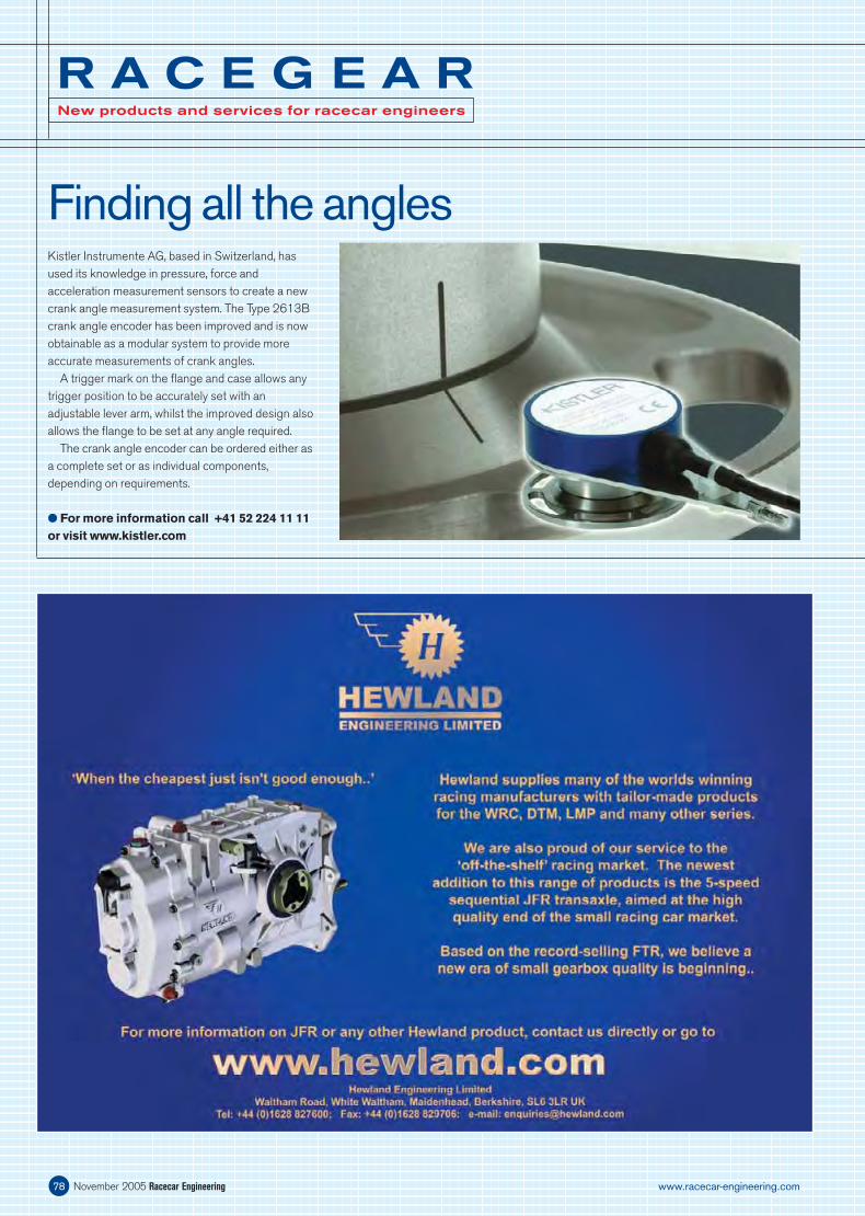
November 2005 Racecar Engineering78 www.racecar-engineering.com
R A C E G E A RNew products and services for racecar engineers
Finding all the anglesKistler Instrumente AG, based in Switzerland, has used its knowledge in pressure, force and acceleration measurement sensors to create a new crank angle measurement system. The Type 2613B crank angle encoder has been improved and is now obtainable as a modular system to provide more accurate measurements of crank angles.
A trigger mark on the fl ange and case allows any trigger position to be accurately set with an adjustable lever arm, whilst the improved design also allows the fl ange to be set at any angle required.
The crank angle encoder can be ordered either as a complete set or as individual components, depending on requirements.
For more information call +41 52 224 11 11 or visit www.kistler.com
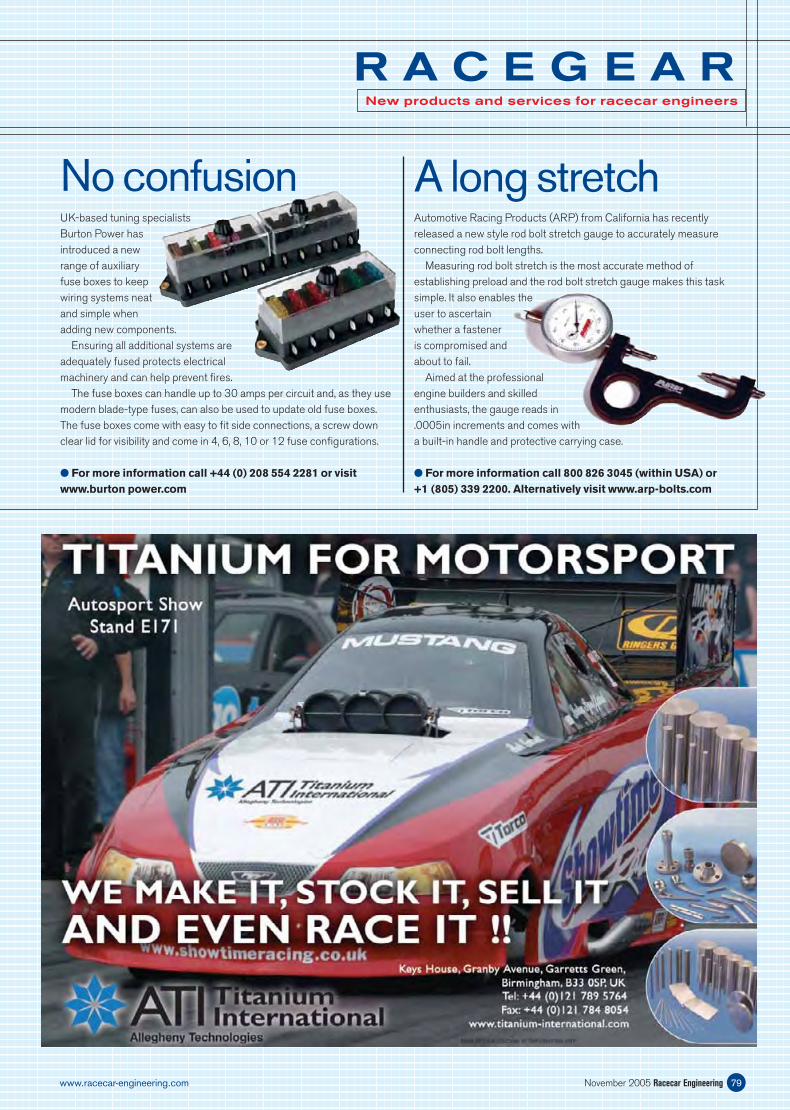
79November 2005 Racecar Engineeringwww.racecar-engineering.com
R A C E G E A RNew products and services for racecar engineers
No confusionUK-based tuning specialists Burton Power has introduced a new range of auxiliary fuse boxes to keep wiring systems neat and simple when adding new components.
Ensuring all additional systems are adequately fused protects electrical machinery and can help prevent fi res.
The fuse boxes can handle up to 30 amps per circuit and, as they use modern blade-type fuses, can also be used to update old fuse boxes. The fuse boxes come with easy to fi t side connections, a screw down clear lid for visibility and come in 4, 6, 8, 10 or 12 fuse confi gurations.
For more information call +44 (0) 208 554 2281 or visit www.burton power.com
Automotive Racing Products (ARP) from California has recently released a new style rod bolt stretch gauge to accurately measure connecting rod bolt lengths.
Measuring rod bolt stretch is the most accurate method of establishing preload and the rod bolt stretch gauge makes this task simple. It also enables the user to ascertain whether a fastener is compromised and about to fail.
Aimed at the professional engine builders and skilled enthusiasts, the gauge reads in .0005in increments and comes with a built-in handle and protective carrying case.
For more information call 800 826 3045 (within USA) or +1 (805) 339 2200. Alternatively visit www.arp-bolts.com
A long stretch
Bleedin ’em dryUK-based quality tool manufacturer, Sykes-Pickavant, has released a new vacuum-operated brake bleeding system to empty the brake system of all brake fl uid. Using vacuum operation to draw the unwanted fl uid from the master cylinder reservoir is far more effi cient than the traditional method of pushing the fl uid through with pressure.
It also simplifi es the process of brake and clutch fl uid changes
R A C E G E A RNew products and services for racecar engineers
November 2005 Racecar Engineering80 www.racecar-engineering.com
Dirt excluders
High performance US suspension component supplier Hyperco has come up with a new line of products to protect its existing range of hydraulic spring perches.
The new ‘Dirt Jackets’ are manufactured from a waterproof, high-density material and, with Velcro closures, are designed to shield perches from the ingression of dirt or grime. This, it is claimed, will prolong the life of the unit and increase performance between rebuilds. Dirt Jackets are one size fi ts all.
For more information call +1 574 753 6622 or 800 365 2645 within the US. Alternatively visit www.hypercoils.com
By Mark Jenkins, Ken Pasternak, Richard WestFormula 1 is a business, but it has characteristics that place it distinctly apart from businesses outside motorsport. It operates on as level a playing fi eld as you
Performance at the limit
By Karl LudvigsenFrom an engineering perspective, nothing links these engines other than the number of cylinders. Yet, as a group, it needs no further justifi cation because anyone with an enthusiasm for engineering will know exactly
The V12 Engine
as, once the old fl uid has been removed from the system, the reservoir is simply topped up with fresh fl uid and sucked through the system by vacuum pressure.
By using a vacuum instead of a pressure bleeding system, fl uid changes are quicker, the risk of spillage is reduced and pressure-tight seals on master cylinder reservoirs are no longer needed.
For more information call +44 (0) 1922 702200 or visit www.sptools.co.uk
what they are in for. In this tome, the author has tried to cover every V12 engine that ever travelled under its own steam in a car.
The list includes a number of racing cars, including the fi rst GP V12 from Delage, the endurance engines from Lagonda and the methanol-burning twelves from Mercedes and Auto Union in the 1930s. Post war, Ferrari comes under the spotlight followed by Maserati, BRM and Matra before F1 adopted the format as the standard for a while. At the end it devotes a few pages to explaining how the more than 20 million possible fi ring orders for a V12 were whittled down to the nine used.
Such is the scope that, even running to 424 pages, there is a limit to the depth of its technical content. But, as an entertaining browse through some of the most charismatic engine projects in history, it offers a very absorbing journey.
Published by Haynes, hardback, 424 pages, £40.00
are likely to fi nd in the world of commerce and its competitors are exposed to a stark comparison every fortnight throughout the season. Consequently, ineffi ciencies or performance-sapping internal confl icts become apparent in a way non-motorsport businesses never encounter.
It is within the culture this environment breeds that this book has searched for examples of practices that can be applied to benefi t mainstream business. Much emphasis is given to leadership and management using scenarios like the F1 pitstop as an example. It also looks at techniques like leveraging relationships for maximum benefi t.
Perhaps the greatest value of this book is that Formula 1 attracts some of the brightest, most capable people in business and their advice and insight is quoted throughout. Admittedly, translating this into the non-motorsport world may not be so straightforward, but applying them in other areas of motorsport would be a very realistic goal.
Published by Cambridge University Press, hardback, 238 pages, £25.00
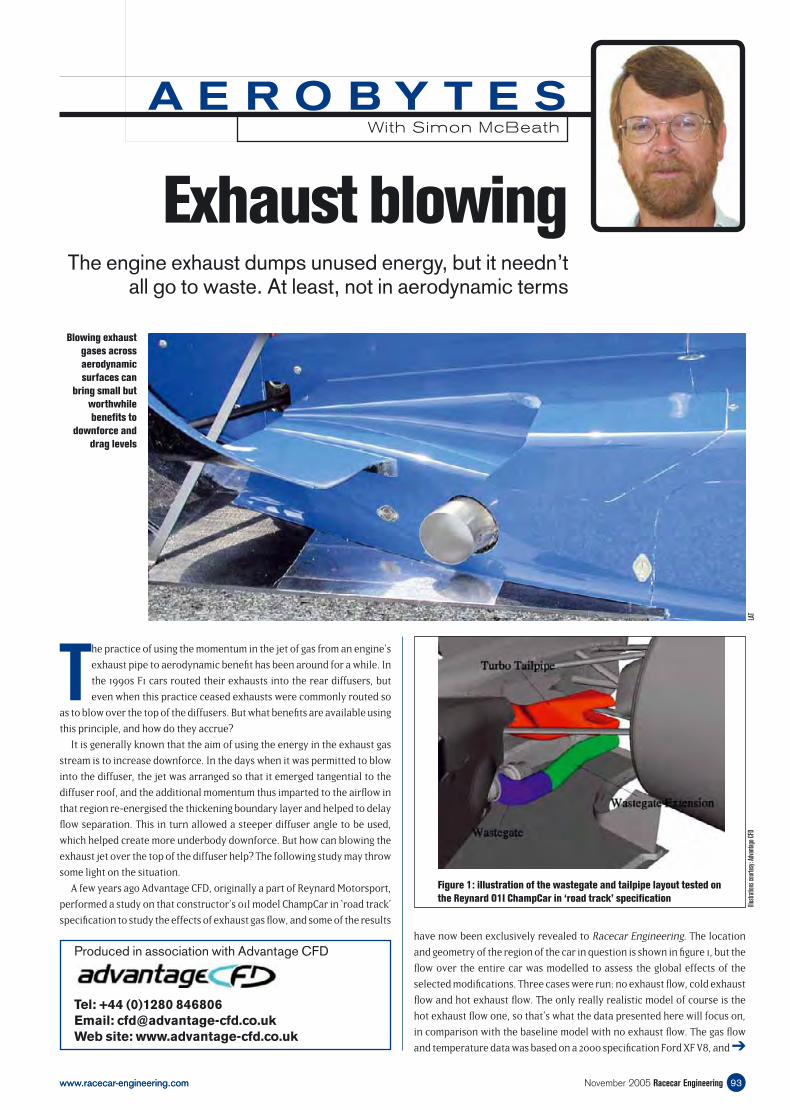
Exhaust blowingThe engine exhaust dumps unused energy, but it needn’t
all go to waste. At least, not in aerodynamic terms
The practice of using the momentum in the jet of gas from an engine’s
exhaust pipe to aerodynamic benefi t has been around for a while. In
the 1990s F1 cars routed their exhausts into the rear diffusers, but
even when this practice ceased exhausts were commonly routed so
as to blow over the top of the diffusers. But what benefi ts are available using
this principle, and how do they accrue?
It is generally known that the aim of using the energy in the exhaust gas
stream is to increase downforce. In the days when it was permitted to blow
into the diffuser, the jet was arranged so that it emerged tangential to the
diffuser roof, and the additional momentum thus imparted to the airfl ow in
that region re-energised the thickening boundary layer and helped to delay
fl ow separation. This in turn allowed a steeper diffuser angle to be used,
which helped create more underbody downforce. But how can blowing the
exhaust jet over the top of the diffuser help? The following study may throw
some light on the situation.
A few years ago Advantage CFD, originally a part of Reynard Motorsport,
performed a study on that constructor’s 01I model ChampCar in ‘road track’
specifi cation to study the effects of exhaust gas fl ow, and some of the results
have now been exclusively revealed to Racecar Engineering. The location
and geometry of the region of the car in question is shown in fi gure 1, but the
fl ow over the entire car was modelled to assess the global effects of the
selected modifi cations. Three cases were run: no exhaust fl ow, cold exhaust
fl ow and hot exhaust fl ow. The only really realistic model of course is the
hot exhaust fl ow one, so that’s what the data presented here will focus on,
in comparison with the baseline model with no exhaust fl ow. The gas fl ow
and temperature data was based on a 2000 specifi cation Ford XF V8, and ➔
Produced in association with Advantage CFD
Tel: +44 (0)1280 846806 Email: [email protected] Web site: www.advantage-cfd.co.uk
Figure 1: illustration of the wastegate and tailpipe layout tested on
the Reynard O1I ChampCar in ‘road track’ specifi cation
www.racecar-engineering.com 93November 2005 Racecar Engineeringwww.racecar-engineering.com
A E R O B Y T E SWith Simon McBeath
Illus
tratio
ns c
ourtes
y: A
dvan
tage
CFD
Blowing exhaust
gases across
aerodynamic
surfaces can
bring small but
worthwhile
benefi ts to
downforce and
drag levels
LAT
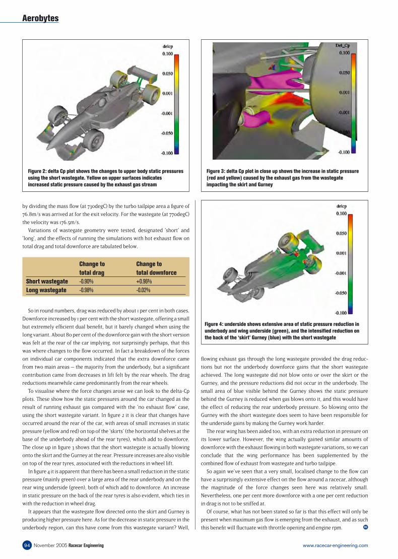
by dividing the mass fl ow (at 730degC) by the turbo tailpipe area a fi gure of
76.8m/s was arrived at for the exit velocity. For the wastegate (at 770degC)
the velocity was 176.5m/s.
Variations of wastegate geometry were tested, designated ‘short’ and
‘long’, and the effects of running the simulations with hot exhaust fl ow on
total drag and total downforce are tabulated below.
fl owing exhaust gas through the long wastegate provided the drag reduc-
tions but not the underbody downforce gains that the short wastegate
achieved. The long wastegate did not blow onto or over the skirt or the
Gurney, and the pressure reductions did not occur in the underbody. The
small area of blue visible behind the Gurney shows the static pressure
behind the Gurney is reduced when gas blows onto it, and this would have
the effect of reducing the rear underbody pressure. So blowing onto the
Gurney with the short wastegate does seem to have been responsible for
the underside gains by making the Gurney work harder.
The rear wing has been aided too, with an extra reduction in pressure on
its lower surface. However, the wing actually gained similar amounts of
downforce with the exhaust fl owing in both wastegate variations, so we can
conclude that the wing performance has been supplemented by the
combined fl ow of exhaust from wastegate and turbo tailpipe.
So again we’ve seen that a very small, localised change to the fl ow can
have a surprisingly extensive effect on the fl ow around a racecar, although
the magnitude of the force changes seen here was relatively small.
Nevertheless, one per cent more downforce with a one per cent reduction
in drag is not to be sniffed at.
Of course, what has not been stated so far is that this effect will only be
present when maximum gas fl ow is emerging from the exhaust, and as such
this benefi t will fl uctuate with throttle opening and engine rpm.
Figure 4: underside shows extensive area of static pressure reduction in
underbody and wing underside (green), and the intensifi ed reduction on
the back of the ‘skirt’ Gurney (blue) with the short wastegate
Figure 3: delta Cp plot in close up shows the increase in static pressure
(red and yellow) caused by the exhaust gas from the wastegate
impacting the skirt and Gurney
RE
Aerobytes
Figure 2: delta Cp plot shows the changes to upper body static pressures
using the short wastegate. Yellow on upper surfaces indicates
increased static pressure caused by the exhaust gas stream
November 2005 Racecar Engineering94 www.racecar-engineering.com
Change to Change to
total drag total downforce
Short wastegate -0.90% +0.96%
Long wastegate -0.98% -0.02%
So in round numbers, drag was reduced by about 1 per cent in both cases.
Downforce increased by 1 per cent with the short wastegate, offering a small
but extremely effi cient dual benefi t, but it barely changed when using the
long variant. About 80 per cent of the downforce gain with the short version
was felt at the rear of the car implying, not surprisingly perhaps, that this
was where changes to the fl ow occurred. In fact a breakdown of the forces
on individual car components indicated that the extra downforce came
from two main areas – the majority from the underbody, but a signifi cant
contribution came from decreases in lift felt by the rear wheels. The drag
reductions meanwhile came predominantly from the rear wheels.
To visualise where the force changes arose we can look to the delta-Cp
plots. These show how the static pressures around the car changed as the
result of running exhaust gas compared with the ‘no exhaust fl ow’ case,
using the short wastegate variant. In fi gure 2 it is clear that changes have
occurred around the rear of the car, with areas of small increases in static
pressure (yellow and red) on top of the ‘skirts’ (the horizontal shelves at the
base of the underbody ahead of the rear tyres), which add to downforce.
The close up in fi gure 3 shows that the short wastegate is actually blowing
onto the skirt and the Gurney at the rear. Pressure increases are also visible
on top of the rear tyres, associated with the reductions in wheel lift.
In fi gure 4 it is apparent that there has been a small reduction in the static
pressure (mainly green) over a large area of the rear underbody and on the
rear wing underside (green), both of which add to downforce. An increase
in static pressure on the back of the rear tyres is also evident, which ties in
with the reduction in wheel drag.
It appears that the wastegate fl ow directed onto the skirt and Gurney is
producing higher pressure here. As for the decrease in static pressure in the
underbody region, can this have come from this wastegate variant? Well,
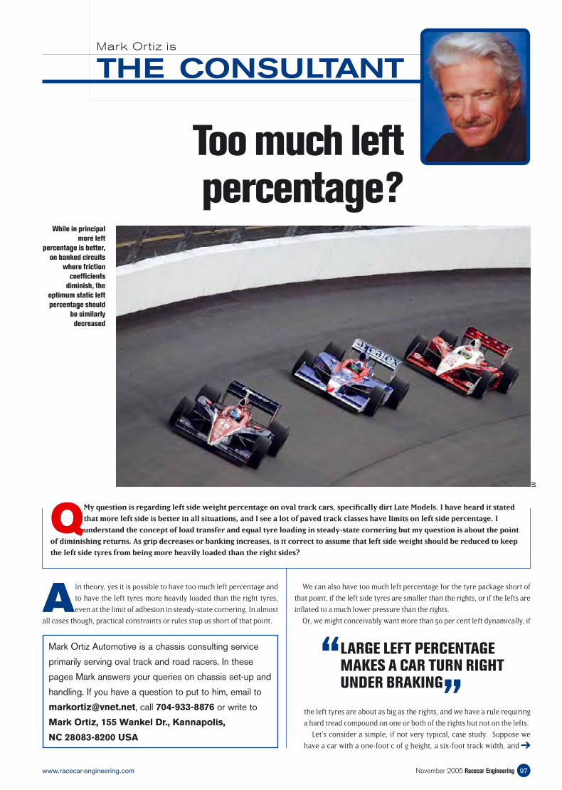
Too much left percentage?
AIn theory, yes it is possible to have too much left percentage and
to have the left tyres more heavily loaded than the right tyres,
even at the limit of adhesion in steady-state cornering. In almost
all cases though, practical constraints or rules stop us short of that point.
We can also have too much left percentage for the tyre package short of
that point, if the left side tyres are smaller than the rights, or if the lefts are
infl ated to a much lower pressure than the rights.
Or, we might conceivably want more than 50 per cent left dynamically, if
➔
97November 2005 Racecar Engineeringwww.racecar-engineering.com
THE CONSULTANTMark Ortiz is
Mark Ortiz Automotive is a chassis consulting service
primarily serving oval track and road racers. In these
pages Mark answers your queries on chassis set-up and
handling. If you have a question to put to him, email to
[email protected], call 704-933-8876 or write to
Mark Ortiz, 155 Wankel Dr., Kannapolis,
NC 28083-8200 USA
QMy question is regarding left side weight percentage on oval track cars, specifi cally dirt Late Models. I have heard it stated
that more left side is better in all situations, and I see a lot of paved track classes have limits on left side percentage. I
understand the concept of load transfer and equal tyre loading in steady-state cornering but my question is about the point
of diminishing returns. As grip decreases or banking increases, is it correct to assume that left side weight should be reduced to keep
the left side tyres from being more heavily loaded than the right sides?
While in principal
more left
percentage is better,
on banked circuits
where friction
coeffi cients
diminish, the
optimum static left
percentage should
be similarly
decreased
LAT
“ LARGE LEFT PERCENTAGE MAKES A CAR TURN RIGHT UNDER BRAKING
”the left tyres are about as big as the rights, and we have a rule requiring
a hard tread compound on one or both of the rights but not on the lefts.
Let’s consider a simple, if not very typical, case study. Suppose we
have a car with a one-foot c of g height, a six-foot track width, and
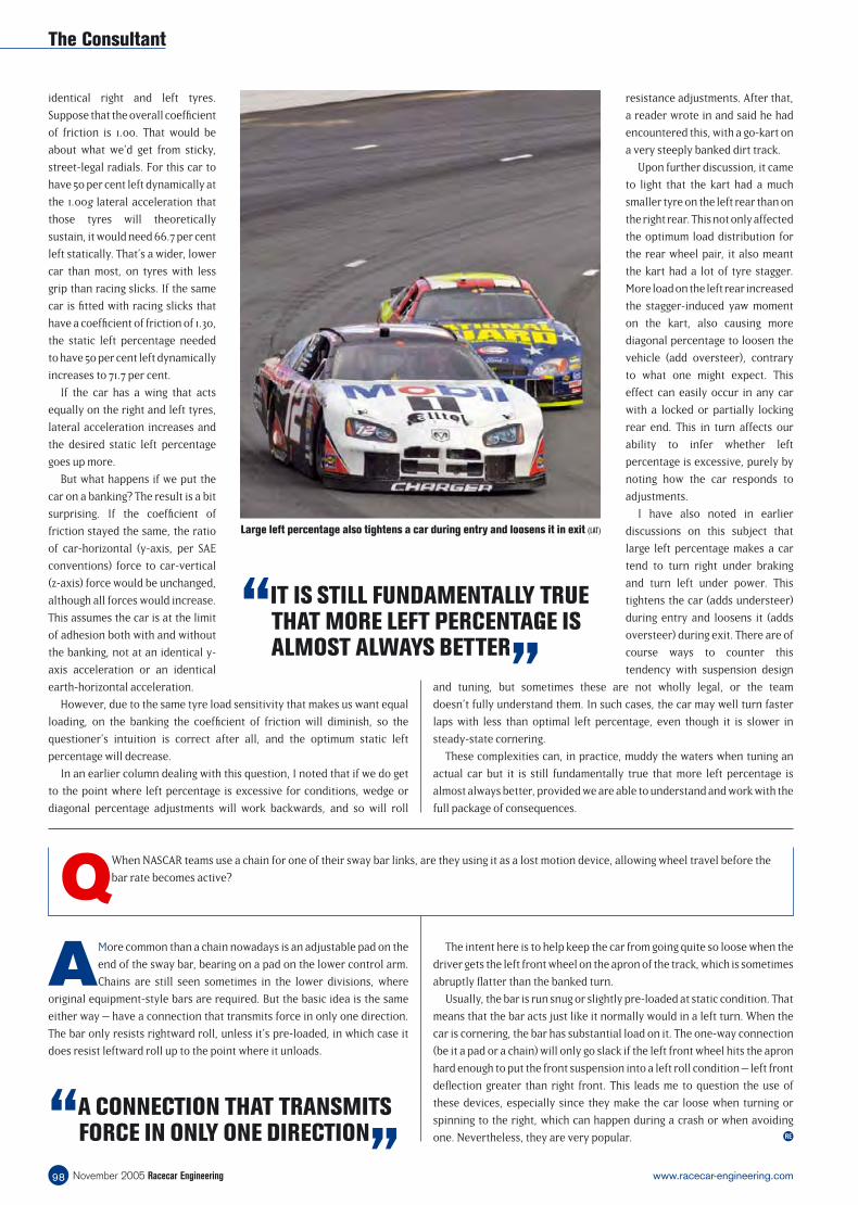
resistance adjustments. After that,
a reader wrote in and said he had
encountered this, with a go-kart on
a very steeply banked dirt track.
Upon further discussion, it came
to light that the kart had a much
smaller tyre on the left rear than on
the right rear. This not only affected
the optimum load distribution for
the rear wheel pair, it also meant
the kart had a lot of tyre stagger.
More load on the left rear increased
the stagger-induced yaw moment
on the kart, also causing more
diagonal percentage to loosen the
vehicle (add oversteer), contrary
to what one might expect. This
effect can easily occur in any car
with a locked or partially locking
rear end. This in turn affects our
ability to infer whether left
percentage is excessive, purely by
noting how the car responds to
adjustments.
I have also noted in earlier
discussions on this subject that
large left percentage makes a car
tend to turn right under braking
and turn left under power. This
tightens the car (adds understeer)
during entry and loosens it (adds
oversteer) during exit. There are of
course ways to counter this
tendency with suspension design
and tuning, but sometimes these are not wholly legal, or the team
doesn’t fully understand them. In such cases, the car may well turn faster
laps with less than optimal left percentage, even though it is slower in
steady-state cornering.
These complexities can, in practice, muddy the waters when tuning an
actual car but it is still fundamentally true that more left percentage is
almost always better, provided we are able to understand and work with the
full package of consequences.
identical right and left tyres.
Suppose that the overall coeffi cient
of friction is 1.00. That would be
about what we’d get from sticky,
street-legal radials. For this car to
have 50 per cent left dynamically at
the 1.00g lateral acceleration that
those tyres will theoretically
sustain, it would need 66.7 per cent
left statically. That’s a wider, lower
car than most, on tyres with less
grip than racing slicks. If the same
car is fi tted with racing slicks that
have a coeffi cient of friction of 1.30,
the static left percentage needed
to have 50 per cent left dynamically
increases to 71.7 per cent.
If the car has a wing that acts
equally on the right and left tyres,
lateral acceleration increases and
the desired static left percentage
goes up more.
But what happens if we put the
car on a banking? The result is a bit
surprising. If the coeffi cient of
friction stayed the same, the ratio
of car-horizontal (y-axis, per SAE
conventions) force to car-vertical
(z-axis) force would be unchanged,
although all forces would increase.
This assumes the car is at the limit
of adhesion both with and without
the banking, not at an identical y-
axis acceleration or an identical
earth-horizontal acceleration.
However, due to the same tyre load sensitivity that makes us want equal
loading, on the banking the coeffi cient of friction will diminish, so the
questioner’s intuition is correct after all, and the optimum static left
percentage will decrease.
In an earlier column dealing with this question, I noted that if we do get
to the point where left percentage is excessive for conditions, wedge or
diagonal percentage adjustments will work backwards, and so will roll
RE
November 2005 Racecar Engineering98 www.racecar-engineering.com
The Consultant
“IT IS STILL FUNDAMENTALLY TRUE THAT MORE LEFT PERCENTAGE IS ALMOST ALWAYS BETTER
”
Large left percentage also tightens a car during entry and loosens it in exit (LAT)
“A CONNECTION THAT TRANSMITS FORCE IN ONLY ONE DIRECTION
”
AMore common than a chain nowadays is an adjustable pad on the
end of the sway bar, bearing on a pad on the lower control arm.
Chains are still seen sometimes in the lower divisions, where
original equipment-style bars are required. But the basic idea is the same
either way – have a connection that transmits force in only one direction.
The bar only resists rightward roll, unless it’s pre-loaded, in which case it
does resist leftward roll up to the point where it unloads.
QWhen NASCAR teams use a chain for one of their sway bar links, are they using it as a lost motion device, allowing wheel travel before the
bar rate becomes active?
The intent here is to help keep the car from going quite so loose when the
driver gets the left front wheel on the apron of the track, which is sometimes
abruptly fl atter than the banked turn.
Usually, the bar is run snug or slightly pre-loaded at static condition. That
means that the bar acts just like it normally would in a left turn. When the
car is cornering, the bar has substantial load on it. The one-way connection
(be it a pad or a chain) will only go slack if the left front wheel hits the apron
hard enough to put the front suspension into a left roll condition – left front
defl ection greater than right front. This leads me to question the use of
these devices, especially since they make the car loose when turning or
spinning to the right, which can happen during a crash or when avoiding
one. Nevertheless, they are very popular.