Embed Size (px)
Citation preview

RACE CONDITION IN J-K FLIP FLOP
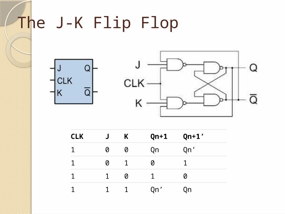
The J-K Flip Flop
CLK J K Qn+1 Qn+1’1 0 0 Qn Qn’1 0 1 0 11 1 0 1 01 1 1 Qn’ Qn

The J-K Flip Flop (contd.)

Timing Race
Many cascaded flip-flops, clocked simultaneously with the input being passed to the output
The propagation delay in each device will be cumulative and add up
If data doesn't ripple through the line and become stable at each output before the next clock, bad information passes into the next stage. This is called timing race.
Race conditions give you bad data

Timing Race (contd.)
It takes at the most 45ns to get through each flip-flop Approximate window of 180ns for which data is invalid Insignificant while counting hours but significant for
counting milliseconds Ton > Overall Tpd

Race Condition In J-K Flip Flops
What?Takes place when both inputs J and K are
‘high’ (J=K=1)Multiple instances of toggling of the output in
level triggered J-K flip flopsAmbiguous output and erratic behaviourMay not always produce predictable output

Why?Level triggered circuitsOutput will change every time the input
changesUnwanted changes in input may occur due to
noise, consequently changing the outputOccurs mainly because of the feedback
connections (Q &Qbar)
Race Condition In J-K Flip Flops

The time period of the clock pulse is greater than the propagation delay of the latch/flip flop
Output changes or toggles in a single clock period
If it toggles even number of times the output is same but if it toggles odd number of times then the output is complemented
This leads to ambiguity
Race Condition In J-K Flip Flops

How? When J= K =1 and clock= 1, the value of output
should be toggled Practically, we do not get toggling
Race Condition In J-K Flip Flops

Solutions1. If Ton < Tpd
2. Edge Triggering

Output is affected only at the time of presence of edge i.e. only during the rising or falling edge of a clock pulse
When the input clock pulse makes a +ve/-ve going transition, the input is transferred to output
Changes in input when clock is maintained at a steady 1 value do not affect Q
A -ve pulse transition does not affect the output and nor does when clock pulse is 0
Thus, edge triggering eliminates any feedback problem
Solutions

3. J-K Master Slave flip flop Two latches connected serially Clock is connected directly to Master and inverted to Slave Inputs fed at the +ve edge and outputs available at the -ve
edge
Solutions
When clock is high – Master is functional and when clock is low – Slave is functional

The outputs from the “master” flip flop are only “seen” by the gated “slave” flip flop when the clock input goes “LOW” to logic level “0″
Master-Slave JK Flip flop is a “Synchronous” device as it only passes data with the timing of the clock signal
Solutions

THANK YOU!!!