Embed Size (px)
Citation preview

https://ntrs.nasa.gov/search.jsp?R=20030068451 2018-09-01T20:08:45+00:00Z

J?TA!MONAL ADVISOBY COMMIT'I!EZ FOR AEpiONAUTICS
TECHNICAL ~ M O ~ ~ ~ NO. 1169 _LIP
mscmwm OF RUSSIAN AIRCRAFT ENGINES
By E, Denkmeier and K. Gross
Only the f ollovtng excerpts, which describe the Russian developed s w i r l t h ro t t l e , have been translated and a re presented here.
A , DESCRIPTIOB OF AM 35 AND AM 38 ENGINS
IT. Construction of Engines
10. Supercharger. - The AM 35 supercharger and the AM 38 super- Mounted on charge-) a re of a single-stage centrifugal type.
a 16-blade half-open impeller is a s t e e l inducer. Adjoinin& the impeller i s a nonbladed annular casing of large r ad ia l dimension t o which the swirl t h r o t t l e is attached ( f i g s . 2 1 and 22), cal ly most modern par t i s ths swirl th ro t t l e ( f ig . 26) mounted on the i n l e t t o the supercharger; the mechanical construction of t h i s t h ro t t l e is s t r ikingly simple. Because the s w l r l t h ro t t l e has up t o the prescnt t i m e never been found on other engines, the assumption may be made that t h i s t h ro t t l e is a purely Russian development. Twelve radial guide vanes carried by journals at the outer ends a re simultaneously con- trolled by means of toothed segments and a toothed ring. Motion is transmitted by a boost-preesure regulator mounted on the side of' the supercharger housing t o one of the guide vanes. vanes i n an oblique posit ion imparts a sp i r a l motion t o the a i r in the direction of rotat ion of the supercharger and reduces ths supercharger driving power. The smatler amount of supercharger work is accompanied by a smaller temperature r i s e i n the compressor. t h ro t t l e a l so has the functions of a boost-pressure regulatlnz valve, i t s ef fec t on the adiabatic pressure head of the supsrcharger is greatest near sea leve l because of the markedly oblique set t ing of the vanes and decreases with increasing a l t i t u d e , t ha t is, w i t h the increase of the angle to which the blades are open.
The techni-
Placement of the
Because the s w i r l
*"Beschreibung der russischen Flugaotorcn "AM 35" und "AM 38." Deutsche Luftfahrtforschung, Untersuchungen und Mitteilungen Nr. 690. Ileutsche Versuchsanstalt f. Luftfahrt E . V., Ins t . f . Triebwerlc- Gestaltung, Motoren-Pr$ffeld, Berlin-Adlcrshof I ZMB, A u g . 1, 1942.

2 NACA "M No. 1169
The supercharger work saved by t h i s method of th ro t t l i ng is con- siderable; it will be discussed fur ther i n the description of invest i - gations, which follows.
The awlrl t h ro t t l e instal led i n the AM 35 and the AM 38 a l lovs very high supercharger speeds a t sea level and therefore allows the elimination of a gear shif-t for low a l t i tudes ,
B. TEST RUNS OF AM 35 AND AM 38 EI\JGIIlES
TI. Test Rim of AM 38 Engine
The engine is a 9urel.y low-altitude engine equipped with a super- charger, Lhe f u l l pressure a l t i t ude of which is 2 .2 kilometers. The influence of tho s w i r l th ro t t le , which is noticeable only below f u l l pressure a l t i tude , d i d not appear very strongly i n these t e s t s because of the low design a l t i t ude of the supercharger. This character is t ic first became f u l l y evident in the opemtion of the AM 35-A engine, which is equipped with a hiGh-altttude sugercharger. [NACA comment : The statement had prev-ioualy been made that "The superchargers of the two enginea a re of exac t l r the Sam design except for the gear ratios", namely 11.05:l and 14.6:1,]
. . The maximum o u t p t was reached a t an a l t i t u d e of approxi- mately 2.2 k i lowte r s ; f rom there the output curve passes into the norrmzlly f a l l i n g branch by wax of an arc. This are-shaped bend a t f u l l pressure a l t i t ude i e caused by the s w i r l t h r o t t l e , of the swirl thro t t le , t o which i n e f fec t the poss ib i l i ty of elim- inating the soa-level stage of Lhe supercharger is due, becomes apparent i n a very considerable increase of output below full pres-
. sure a l t i t u d e as compared t o operation with the n o m 1 th ro t t l e . example, if f o r the output curve a t pL = 1.56 atmospheres absolute and n = 2150 rpm, the indicated outputs of the engine with and without the s w i r l t h ro t t l e ake calculated according t o
The advantage
For
71 '14 %, with th ro t t l e 632 Ni with t h r o t t l e =
where q i = 0.32, pL = 1.56 atmospheres absolute, tL = 95O C, and n = 2150 rpm.
f o r indicated output with swikl t h ro t t l e a t
0.32 x 714 x 492.0 Ni with fuhrottle = 63 2

3
Because the quant i t ies of a i r wfth and without s w i r l t h ro t t l e a t equal boost pressure vary i n proportion t o the absolute teapex-ature, f o r Qie a i r delivery without swirl t h ro t t l e a t % = 1.56 atmosphei-es absolute and t L = 116’ C the following r e su l t s a re obtained:
TL with th ro t t l e % without throt’cle = &cut thr;t”s; CZ with
368 3 89 = - X 4920 = 4650 kilograms
t h ro t t l e
per hour.
and theref ore
.- 0 0 3 2 714 4650 = 1680 horsepower Ni without t h ro t t l e - --,----I- 652
A-t an a l t i t ude o r 0, a gain i n power of 130 horsepower, which decreases t o 0 a t f u l l pressure a l l i t i d e (hatched area i n f i g . 301, i s calculated. The s m e j=ower gain i s found i n ac tua l tes t . The reduction of temperature due t o the mirl thro-ttle was measured as 21’ C; corres,ponii-i-ng t o the teiliperature behavior of the engine, a power gain 09 70 horsepower i s at ta ined, reduction in power used t o drive the supercharger, in accordance with
To t h i s gain i s added the
with swirl th ro t t l e
0’24 8o --.- 427 = 149.5 horsepower Ne-1 = 1- 75
without swirl th ro t t l e
CN,,1 = 28.5 horsepower
0,192 AHw Eiw t o t a l ___I_ =
4
@,4@5 AEad iiz-total=
NACA TN No. 1x69
Thus with a 40.5-percent reduction of the adiabat ic pressure head a saving i n supercharger driving power of 19.2 percsnt is obtained.
For the 100 horsepower calculated power gain, an experimentally observed gain of i s gained from the reduction of temperature and about 30 horsepower from the reduction of power i n p u t t o the supercharger. power gain as f u l l pressure a l t i t ude is approached is caused by the increased opening angle of the swir-1 th ro t t l e ( f i g . 30), which i s con- t ro l led by the boost -pressure i-egulator.
70 + 28.5 = 98.5 horsepover, t h a t is, 70 horsepower,
The decrease i n
[NACA comment: A fur ther power gain shou1.d r e su l t from the Decreased mixture temper- decreased supercharger ou t le t temperature.
a ture w i l l r e su l t i n higher permissible power output with f u e l of a given knock rating.]
E'igwe 31 shows the 3ressu.res 3eliind khe sunerchar&er Corre8pXldiPg t o the altitude-power gra2h. a s i s usual w i t h coriveritiorial regulating valves. a l t i t t lae i s there, due t o the nature of tile s w i r i t h ro t t l e , a curved t rangi t ion instead oi' an angle i n tke curve. The pressme l o s s i n suyercharger duct and carburetor with f u l l y opened swirl th ro t t l e amounts to 100 millimeters of mercur:;.
These pressure curves have the same shape Only a t f u l l pressure
The temrperature reduction caused by the swirl th ro t t l e a t fu3.1. pressure a l t i tude is shown i n figure 32. Here the temperature, l i ke the supercharger-outlet pressure, remains a t the same leve l u n t i l above full pressure a l t i t ude . meters show the curve of boost a i r teqeratur 'e t ha t would be attained without the s w i r l t h r o t t l e 4 does the actual. tem2erature fiffference corresponding t o operation with open s w i r ? t h r o t t l e . The in l e t - a i r temperatures t o the supercharger correspond t o the Ina temperatures
In sp i te of the re la t ive ly great acattering of the data points, it may be seen that each curve is convex downwardly u n t i l f u l l pressure a l t i t ude ' i s reached. The par t 02 the curve r i s ing again as f u l l pressure a l t i t ude i s approached corresponds t o the usual air-quantity curves for raulticylinder engines, which r i s e a t a. uniform r a t e u n t i l f u l l pressure a l t i t ude is reached. I n the same engine, the fmproved
The t h i n Lines below an a l t i t u d e of 3 .2 ki lo-
Only a t an a l t i t ude of 3.2 kilometers reach the values TII - TI
In f igure 33, air consumption is plotted against a l t i tude .

NACA TI4 No. 1169 5
flow coefficient a t l o w a l t i t udes due t o the: swirl th ro t t l e produces an increase in a i r quantity a t sea level. a l t i t u d e , the curves follow a normal course,
Beyond f u l l pressure
Figure 35 shows the var ia t ion of cer ta in engine operating chamcter i s t ics with engine speed, which a t the usua l operating speeds of 1800 t o 2200 rpxn i s ver*y s l igh t . The influence of the s w i r l t h ro t t l e is par t icular ly apparant here i n the boost air temperature. The numbers printed beside the data points indicate the opening angles of the s w i r l t h ro t t l e . Below n = 1640 rpm, the swirl t h ro t t l e is wide open because of the low boost pressure and therefore has no e f f ec t . speed i n the usua l manner. Only with the closing of the awlrl th ro t t l e does a break apgear i n the tem2erature curve. Thereafter, the observed temgeratures run f a r below th temperatures without swirl thro t t le , which a re shown by the tl1l.n Uno. zower and specif ic f u e l consumytion c u r v ~ s .
I n t h i s region the temperature rises as a function of the
Breaks are also evident i n the
111, Test Run of AM 35 Engine
. . . Due t o the greater f u l l pressure a l t i t ude [HACA comment: 6 km], the e f fec t of the we of the swirl t h ro t t l e i s much greater as compred with the AN 38 engine,
. . . . . . F u l l pressuTe a l t i tude is 6 kilometers with an output of
1240 horsepower. Equal pressure a l t i t ude is 9.5 kilometers with an output of 870 horsepower. The power gain produced by the s w i r l t h ro t t l e is made clear ly evident by some data points obtainecl with the th ro t t l e disconnected ( f ig . 40)
Thus a t an a l t i t ude of 2 kilometers, pL = 1.35 atmospheres n = 1750 YTm, a power difference of approximately
By extending t h i s power l ine i n the absolute, and 100 horsepower i s observea, usual manner as a straight, l i ne towards an a l t i t u d e of 0, a t that point with these same ogemting data, a power gain of 150 horsepower, which becomes &ill greater f o r higher spced and higher boost pres- sure, appears. measurements could be made only a t lower speeds and higher a l t i tudes . I n the same f igure the respective opening angles of the swirl th ro t t l e are shown.
Because of the high boost air temperatures, these

6
The respective pressurea ahead of the supercharger -outlet pressures measured a t f figure 41. 1-egulator, The pressure loss i n the a i r duct and the carburetor amounts t o 100 ui l l jmeters of mercury.
Eere the swirl th ro t t l e a c t s simply as a boost pressure
The ef fec t of the mrked temperature reduction produced by the
A t an a l t i t ude of s w l r l t h r o t t l e is most c lear ly evident i n the graph of boost a i r t e q e r a t u r e s plotted itgainst a l t i t ude ( f i g . 4 2 ) . 0 and n = 2050 rpm, there i s a temprature reduction of 43' C, The supercharger pressure has no influence on the tempemture level.
Figure 43 shows air consmytion glcrbted againet a l t i t u d e . Here, as i n the AM 38 engine, the saddle-shaped form of the curves below f u l l pressure a l t i tude m y be observed. The th in Lines show air flow i n the t e s t s with the s w i r l t h ro t t l e disconnected and correspond t o the usua l curves with a clack th ro t t l e . I n these air-consumption curves the e f fec t of the swirl t h ro t t l e is again clear ly evident.
Bie flow coefficient f o r the sans operating condition with and The a i r quantities without s w i r l thro-tt le i s plotted i n figure 44,
f o r the flow coefficient without, swirl thro t t le were extrapolated on the basis of the available d & t a points,
. * .
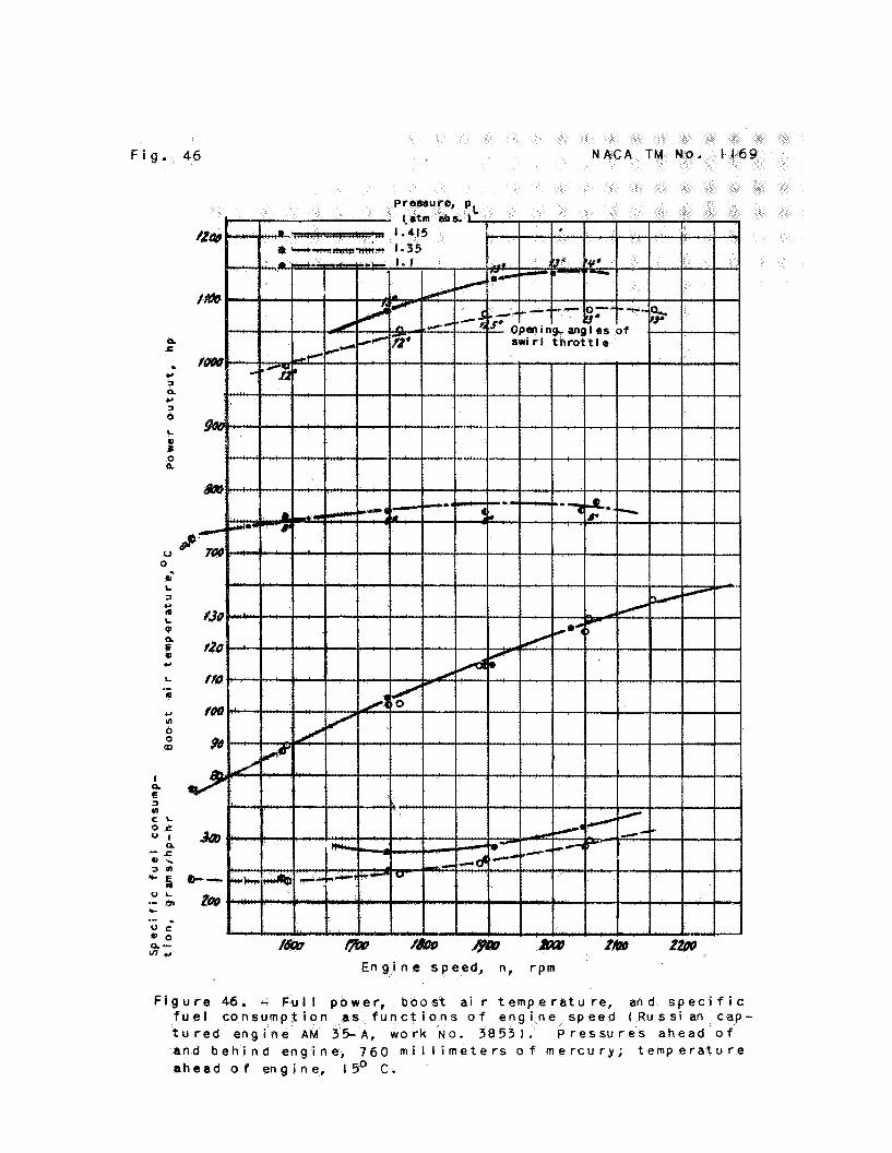
The variation of cer ta in operating character is t ics with the speed (fig. 46) i s very small between n = 1900 t o 2150 rpm. pE = 1.1 atmoapheres absolute, t h i s range extends t o 1600 rpm. Because the high supercharger gear r a t i o i n t h i s engine produces even a t lower engine s p e d s a high supercharger-outlet pressure tha t keeps the s w i r l t h r o t t l e constantly i n an almost closed position, there is no v is ib le e f fec t of the swirl th ro t t l e in these curves, a8 contrasted with those f o r the AM 38 engine. points give the opening angles of the swirl t h r o t t l e .
A t
The numbers adjoining the data
In f igure 53, the curves of e x t e r n 1 driving power are plotted
The against a l t i t ude . The inputs were observed with the normal operating condition of the engine and with open and closed gas th ro t t l e . s w i r l throktle operated i n the n o m 1 manner; t o t h i s operation mus t be a t t r ibuted tho deviation of the curve8 from the normal course below f u l l pressure a l t i t ude because of reduction of supercharger power input. A t an a l t i t ude of H = Q kilometeys, the curves with open and with closed g m th ro t t l e intersect a t the points that corre- spond t o the power necessary t o overcome f r i c t i o n alone without any work of gas changing.
. * .

e . The preaence of the power a t sea level; a l t i tude, which, as
reached a t an a l t i t ude of 2 swirl thyot t le . . ,, ,
Translation by Edward S. Shafer, National Adviaory Commrtttee f o r Aeromutics.

N A C A TM No. 1169 F i g . 3
F i g u r e 3 . - V i e w o f a c c e s s o r i e s a n d s u p e r c h a r g e r o f AM 3 8 .

N A C A TM No. I 1 6 9 F i g s . 2 1 , 2 2
F i g u r e 21. - S u p e r c h a r g e r . V i e w o f swi r l t h r o t t l e.
F i g u r e 22. - S u p e r c h a r g e r w i t h i m p e l l e r .

F i g . 26
F i g u r e 26. - S w i r l t h r o t t l e .

N A C A TM No, 1169

0 z Y L 0 z .
OD m

32
Y L
P
0)
C
WJ C Q)
0 al L 3 +.' a. Q 0
5 m m m 3
.-
.-
a - L . 0 ) - cnrn La Q
TI C
r al
.- n 0) L 3

N A C A TN No, 1169

F i g u r e 35. - F u l l power, boost a i r t e m p e r a t u r e , and s p e c i f l c f u e l consumpt ion a s f u n c t i o n s o f e n g i n e speed ( R u s s i a n c a p t u r e d e n g t n e AM 38, work No. 651. P r e s s u r e a h e a d o f and b e h i n d e n g i n e , 760 m i I l i m e t e r s o f mercury; t e m p e r a t u r e a h e a d o f e n g I n e , ISo C .

TM No, 1169
c
4 -

F i g . 4 1 N A C A TM N O - 1169
E Y
m I
E E
4
L 9)
0) L (d r 0 L 8 CI 3 In
e 0
0 a 0 S (d
Q, L 3 u) u) 0, L 0-
L
C U

N A C A TM No. 1169

F i g . 4 3
c
-.-
N A C A TM No, 1169
> C
+ J m tu .- u)
3:a 0 1 -D:
-9 u-- L .- a 1
In - 9

F i g . 46
E n g i n e s p e e d , n, rpm
u l I p o w e r , boos a i r t e m p e r a t u r e , and s p e c i f i c t i o n as f u n c t i o o f e n g i n e s p e e d ( R u s s i a n cap-
AM 3 % A , w o r k . 3 8 5 3 ) . P r e s s u r e s a h e a d o f n d b e h i n d e n g i n e , 760 m i l l i m e t e r s o f m e r c u r y ; t e m p e r a t u r e
a h e a d o f e n g i n e , I ! 6 ' C .

N A C A TM N O . 1169
a
F i g . 53