Embed Size (px)
Citation preview
R134a REFRIGERATION TECHNICIAN
HANDBOOK
Version 3.0 Updated: June 12, 2012
USACO
TABLE OF CONTENTS 1.0 OVERVIEW ................................................................................................................................................... 4
BACKGROUND ............................................................................................................................................ 4
2.0 HANDBOOK INTRODUCTION ....................................................................................................................... 5
SAFETY AND ENVIRONMENTAL NOTES ...................................................................................................... 5
RECEIVING REFRIGERATED CONTAINERS ON ‘DANGER LIST’ .................................................................... 6
HANDLING PROCEDURES FOR ALL R134A REFRIGERATED UNITS .............................................................. 7
3.0 IDENTIFYING FAKE / COUNTERFEIT R134A REFRIGERATED GAS ................................................................. 8
4.0 R134A REFRIGERATED CYLINDER TESTING UNIT AND PROCEDURES ......................................................... 9
HALIDE TORCH AND VENTILATION HOOD ASSEMBLY ............................................................................... 9
CONGLOBAL‐GAS EXTRACITON AND ANALYSIS RECOVERY SYSTEM (C‐GEARS) ...................................... 11
PROCEDURES FOR EXTRACTING AND TESTING R134A REFRIGERATED GAS CYLINDERS ......................... 12
LABELLING AND TRACKING TEST RESULTS ............................................................................................... 14
5.0 NEW SAFETY REQUIREMENTS FOR SERVICING R134A REFRIGERATED CONTAINERS .............................. 16
ADDITIONAL SAFEGUARDS IMPLEMENTED AT CONGLOBAL INDUSTRIES ............................................... 17
6.0 CONGLOBAL ‐ GAS EXTRACTION AND ANALYSIS RECOVERY SYSTEM (C‐GEARS) ..................................... 19
SAMPLING METHODS ............................................................................................................................... 19
IMPORTANT PRECAUTIONS ...................................................................................................................... 19
C‐GEARS METHOD TO CHECK REFRIGERATION MACHINERY FOR CHLORIDE CONTAMINATION ............ 20
PREPARATION ............................................................................................................................. 20
EQUIPMENT ................................................................................................................................ 20
PREPARING THE C‐GEARS DEVICE ............................................................................................... 22
TAKING SAMPLES FROM REFRIGERATION MACHINE .............................................................................. 23
SAMPLE PORTS ............................................................................................................................ 23
SAMPLING PROCESS .................................................................................................................... 23
FLAME TESTING OF EXTRACTED SAMPLES .................................................................................. 27
FLAME TEST RESULTS .................................................................................................................. 28
CLEANING THE C‐GEARS .............................................................................................................. 29
7.0 EMPLOYEE ACKNOWLEDGMENT............................................................................................................... 30
3 | Page Version 3.0 – Updated: 6/12/2012
USACO
This R134a Refrigeration Technician Handbook was developed as instructional guidelines for refrigeration personnel of ConGlobal and its related companies. We have made this information public solely as a source of information to others who are interested in the servicing of refrigerated containers. We are making this document available as information only and are NOT PROMOTING OR SUGGESTING anyone outside of ConGlobal and its related companies adopt any of the measures contained in this document. Any personnel servicing refrigerated containers should do their own investigation and implement safety policies suited to their specific situation and conditions.
This handbook is intended to be an evolving document and will change as new information is discovered and made available to the industry. Comments and suggestions for improving the effectiveness of the information and procedures contained herein are welcomed and encouraged. Comments and suggestions should be directed to Priscilla Yata at [email protected].
ConGlobal reserves the right to amend, modify and retract any or all parts of this writing as new information may dictate.
4 | Page Version 3.0 – Updated: 6/12/2012
USACO
1.0 OVERVIEW
BACKGROUND
The Refrigerated Container industry has recently experienced several instances whereby refrigerated containers have violently and unexpectedly exploded, resulting in multiple deaths of service technicians around the world. To date, investigations indicate that the explosions were caused by the introduction of counterfeit R134a refrigerant containing, among other gases, significant amounts of R40 (methyl chloride). As of this writing, all of the units that have exploded received a refrigerant gas charge in Vietnam.
However, an additional investigation of “in stock” refrigerant gas supplies at repair companies around the world, as well as on board marine vessels, has turned up counterfeit gas containing R40. Further, in a recent effort by members of the Container Owners Association (COA) who conducted a sampling and testing analysis of several hundred refrigerated units across seven locations, in three different countries, involving units from twelve different SS Lines (or Leasing Companies), revealed that some units which were not serviced in Vietnam were found and confirmed to have counterfeit / contaminated refrigerant containing several different chlorinated gasses, including R40. And as expected, many of the units that received gas service in Vietnam were also found to be contaminated. This supports the growing suspicion that this counterfeit / contaminated refrigerant issue is not isolated to units having been serviced in Vietnam, as originally thought.
Since the early announcements of this problem in 2011, ConGlobal Industries has been involved with an international community of experts, both in the continued investigation as well as the development of test methods to effectively screen units. ConGlobal, along with other industry leaders, has been a driving force behind the development of policies and educational programs designed to safeguard refrigeration service personnel and to prevent the proliferation and spread of counterfeit / contaminated refrigerant. This issue is evolving daily, and we continue to learn more relevant information with each contaminated container identified.
ConGlobal Industries, Inc. and our affiliated service companies of USACO in Costa Rica, Coastal Great Southern on the U.S. East Coast, and ICAVE in Mexico, are among the largest refrigeration service companies in the world. As such, we have taken a very serious view of the issue.
At ConGlobal and all of our affiliated companies, the safety of our personnel as well as safeguarding our client assets are of paramount importance to us. Accordingly, we developed a series of programs, disciplines, and policies based on the most reliable and current information available.
With immediate effect, all ConGlobal refrigeration service facilities and service technicians are adopting the refrigerant gas handling protocol outlined in this handbook, which has been carefully designed to:
1. Safeguard our company personnel 2. Safeguard our customer assets 3. Stop the proliferation of contaminated gas in our industry
5 | Page Version 3.0 – Updated: 6/12/2012
USACO
2.0 HANDBOOK INTRODUCTION
On November 11, 2011, the company issued the first SAFETY BULLETIN relative to news that isolated refrigerated units around the world had exploded, causing casualties, including fatalities.
The Company (herein meant to include ConGlobal Industries, Coastal Great Southern, Container‐Care Icave – Mexico, Container Care Mexico, and USACO Costa Rica) issued a series of policies and procedures, based on information and data known at that time, to protect the safety and well being of our employees who handle, and perform maintenance, repair, and inspection of refrigerated containers.
A great deal of information and knowledge has been accumulated since that date. This Refrigeration Technician Handbook is to be used as the exclusive set of policies and procedures for handling refrigerated container units within and by all company personnel and supersedes any prior communication.
Each and every refrigeration technician in the company must be trained in the procedures outlined in this manual by their supervisor. In addition, every refrigeration service technician will sign the acknowledgment page at the end of this manual, confirming they have read the manual in its entirety; they have been trained by their supervisor; and they fully understand and agree to abide by all the policies and procedures found within this manual. In addition, the General Manager will sign the acknowledgement page, verifying the employee has been trained and is satisfied the employee has the required information and skill to safely work on all refrigeration units.
There will no deviation from these policies and procedures without the explicit written approval of either the President or Director of Safety and Compliance of the company. The policies and procedures found within this manual apply to ALL R134a REFRIGERATION UNITS serviced by our company.
Any refrigeration technician who does not feel completely comfortable complying with the policies and procedures found in this manual must express their concerns with their supervisor prior to commencing work on any refrigerated unit. Any refrigeration technician who observes anything out of the ordinary on any refrigeration unit must immediately stop and report their concerns to their immediate supervisor.
SAFETY AND ENVIRONMENTAL NOTES
A byproduct of burning hydrocarbon chloride is phosgene gas, which is a lethal gas in certain concentrations. To ensure that the Halide Flame test can be safely performed using the ventilation hood described in this handbook; ConGlobal contracted an environmental hygienist from AECOM to test the environment at various distances around the vent hood, including a sampling device located on the testing technician, and at the exhaust outlet. AECOM used OSHA Method 61 as a basis for completing the sample. The sample period lasted five hours and 6 burn tests were performed, 5 of which lasted approximately 30 seconds, and the final burn lasting approximately 1 minute. Both R22 and R134a refrigerant were tested. Since R22 contains chloride, it produces phosgene gas when burned allowing AECOM to test the air quality and record the results.
6 | Page Version 3.0 – Updated: 6/12/2012
USACO
The AECOM technician tested air flow rates, construction of the hood assembly, and smoke test observations. Test media had to be acquired from a lab in New York and was shipped overnight under refrigerated conditions. The test media, after being exposed to the phosgene gas, was returned to the lab, again under refrigerated protection. The test results reported the level of phosgene gas at 1/100 of the OSHA Permissible Exposure Limit during a 4‐hour time frame and thus not representing a significant risk to technicians performing the flame test with a smoke hood in use.
RECEIVING REFRIGERATED CONTAINERS ON ‘DANGER LIST’
To the best of our ability, the Company has loaded client supplied lists of containers in TEC (Terminal Equipment Control System) that have been serviced in Vietnam. These units are designated in TEC as “Danger Units”. Upon arrival at one of our depots, refrigerated containers will be checked to verify they are not identified in TEC as a “DANGER UNIT”.
If a refrigerated unit arrives at your location and is determined to be on our “Danger List”, the container should be immediately moved to an isolated area of the depot, and a gas sample taken (follow the C‐GEARS procedure contained herein). The gas sample should be tested using a Halide Flame Test to determine if chloride is present in the gas. If a “Danger Unit” tests positive for chloride, the container must be marked with a LARGE, RED ‘X’ at the bottom corner of the container, at the door end, and stacked / stored with the units facing each other or the refrigerated unit blocked with another container, preventing unauthorized personnel from tampering with them. A gas test placard should immediately be affixed in a conspicuous location to the front end of the container.
For “Danger Units” failing the Halide Flame Test, cut the plugs off of the units, close to the plug. Put the plug inside the cord box on the front of the unit for any “Danger Unit” that tests positive for chloride.
The machinery should be stacked / stored close enough to the “blocking container” such that a person can not inadvertently walk between them. All “Danger Units” stored in this fashion should be stored at least 25 feet from flammable or combustible materials.
As outlined in the C‐GEARS instructions, a sample of any unit failing the Halide Flame test should be sent to McCampbell Analytical Laboratory in Pittsburg CA for GC‐MS testing.
McCampbell Analytical, Inc. (MAI) 1534 Willow Pass Road Pittsburg, CA 94565
(877) 252-9262 www.mccampbell.com
If a “Danger Unit” passes the Halide Flame test, it is considered safe and can be serviced as directed by the client.
7 | Page Version 3.0 – Updated: 6/12/2012
USACO
HANDLING PROCEDURES FOR ALL R134A REFRIGERATED UNITS
Use the following guidelines on all refrigerated units, including those units on the Danger list that pass the Halide Flame test.
1. First, visually inspect the refrigerated controller to confirm the unit is not set in the “Emergency Run” mode.
2. If the unit has a sightglass, check for any indication of abnormal appearance.
3. When starting the unit, no personnel should be in front of the unit, or be inside the refrigerated container.
4. During start up, all personnel should be no closer than 2 container units (approx. 15 feet) from refrigeration machinery.
5. Before plugging in unit, ensure the refrigeration unit circuit breaker and power switch are in the “on” or “run” (closed) position.
6. Plug the refrigerated unit into a power source that is not directly in front of the refrigerated unit that has the power source breaker turned off.
7. Turn on the breaker at the power source and wait for the refrigerated unit to go through its start up procedure, until the compressor has started and runs for 3‐5 minutes.
8. If the compressor exhibits sounds of improper operation, such as knocking, clanging, buzzing, or other odd sounds, during start up, or if the compressor becomes unusually hot, turn off the breaker at the power source and perform the C‐GEARS procedure. AFTER ALLOWING THE COMPRESSOR TO COOL FOR AT LEAST 30 MINUTES. After passing the C‐GEARS procedure, then troubleshoot as normal. If the unit fails the C‐GEARS procedure, then send the sample to McCampbell Analytical lab and wait for results.
9. If a unit fails to start, disconnect it from power source.
10. The service technician should then use the ‘power plug in hand’ rule when working on unit. This means the technician will have the power cord plug with him prior to commencing any work on the unit.
11. For units that don’t start, and only after power is CONFIRMED disconnected, inspect alarm log for failure indications.
12. For units that require power to view alarms, disconnect the output power to the compressor prior to connecting power.
13. On ANY unit that requires service, whereby gauges must be connected to the unit, the refrigerant must first be tested by using the C‐GEARS extraction procedure. If freon passes the Halide Flame Test, work may commence. If the refrigerant fails Halide Flame Test, no work shall be performed until authorization is given.
14. If any company technician has any doubt or concern about safely working on any refrigerated unit, they should immediately consult with the refrigeration supervisor.
8 | Page Version 3.0 – Updated: 6/12/2012
USACO
3.0 IDENTIFYING FAKE / COUNTERFEIT R134A REFRIGERATED GAS
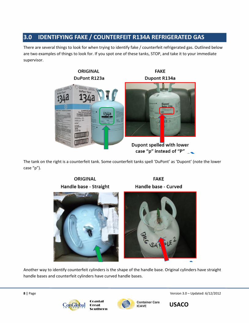
There are several things to look for when trying to identify fake / counterfeit refrigerated gas. Outlined below are two examples of things to look for. If you spot one of these tanks, STOP, and take it to your immediate supervisor.
The tank on the right is a counterfeit tank. Some counterfeit tanks spell ‘DuPont’ as ‘Dupont’ (note the lower case “p”).
Another way to identify counterfeit cylinders is the shape of the handle base. Original cylinders have straight handle bases and counterfeit cylinders have curved handle bases.
9 | Page Version 3.0 – Updated: 6/12/2012
USACO
4.0 R134A REFRIGERATED CYLINDER TESTING UNIT AND PROCEDURES
This section outlines the assembly of the halide flame ventilation hood and the testing procedures for new R134a refrigerated gas cylinders at all ConGlobal refrigeration service facilities. The purpose of testing new R134a cylinders before use in servicing refrigerated containers is to detect whether the R134a cylinder has been contaminated with chlorinated gasses, including R40 (Methyl Chloride).
HALIDE TORCH AND VENTILATION HOOD ASSEMBLY
The unit to test refrigerated gas from cylinders uses the following components and modifications:
• Compact Overspray Collector with dimensions of 18” H X 22” W X 20” D. This piece is referred to as a vent hood, purchased from McMaster‐CARR (Part number 9559T51).
• The vent hood is modified by the following procedures.
o Mounting the unit on two “legs” fabricated out of sheet metal.
o Drilling a hole in the bottom of the vent hood so the halide leak detector can be inserted through the bottom.
o Painting the interior of the vent hood black so the flame can be easily seen.
o Drilling a hole in the left side of the vent hood so the “exploration hose” can be routed to the tank for testing.
o Installing a plexi‐glass cover on the front using a “piano hinge” to contain fumes in hood for ultimate ventilation. (Note: The opening at the bottom of the installed plexi‐glass is intentional to allow for proper air flow.)
o Outfitting the exhaust fan mounted on the rear of the unit with aluminum ducting so the exhaust outlet is at a sufficient distance, as required by local worker safety regulations. For ConGlobal’s North American locations, the exhaust should terminate seven feet above the height of the technician’s head.
10 | Page Version 3.0 – Updated: 6/12/2012
USACO
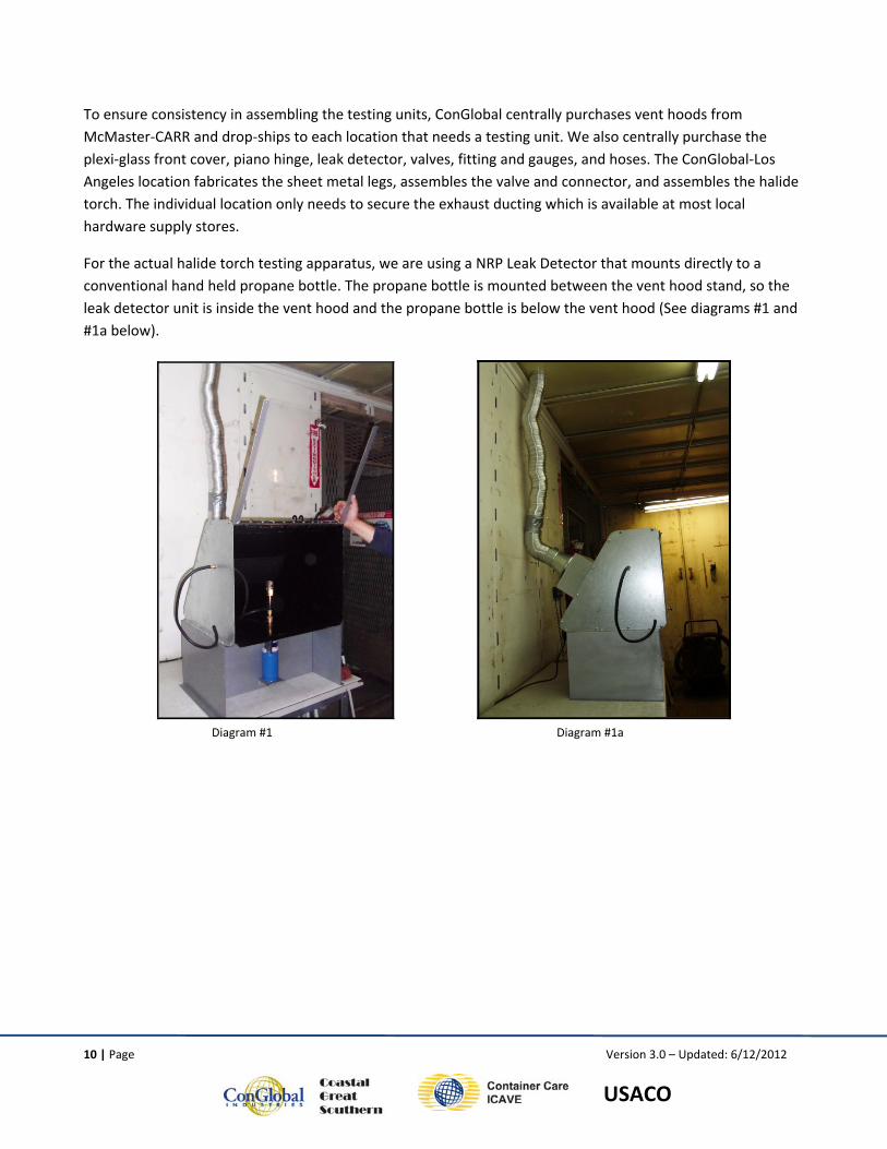
To ensure consistency in assembling the testing units, ConGlobal centrally purchases vent hoods from McMaster‐CARR and drop‐ships to each location that needs a testing unit. We also centrally purchase the plexi‐glass front cover, piano hinge, leak detector, valves, fitting and gauges, and hoses. The ConGlobal‐Los Angeles location fabricates the sheet metal legs, assembles the valve and connector, and assembles the halide torch. The individual location only needs to secure the exhaust ducting which is available at most local hardware supply stores.
For the actual halide torch testing apparatus, we are using a NRP Leak Detector that mounts directly to a conventional hand held propane bottle. The propane bottle is mounted between the vent hood stand, so the leak detector unit is inside the vent hood and the propane bottle is below the vent hood (See diagrams #1 and #1a below).
Diagram #1 Diagram #1a
11 | Page Version 3.0 – Updated: 6/12/2012
USACO
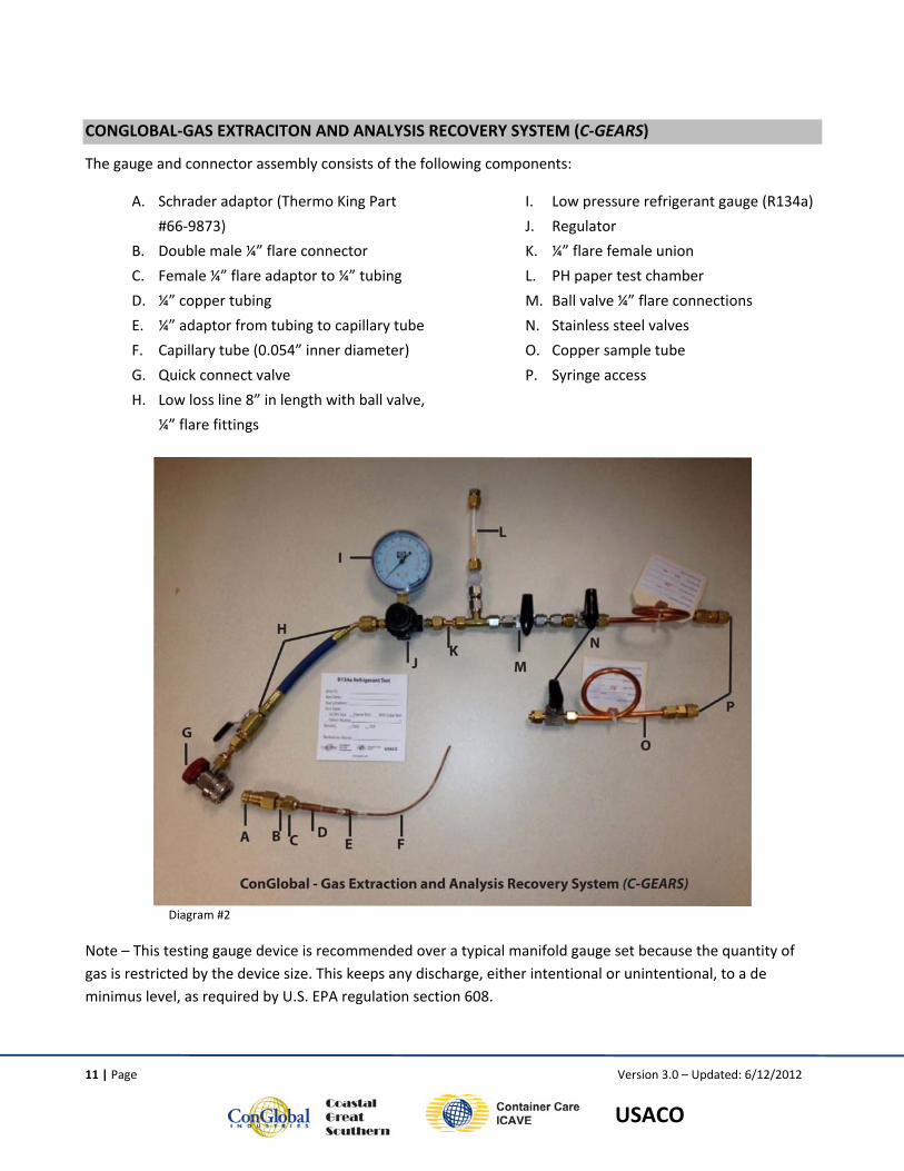
CONGLOBAL‐GAS EXTRACITON AND ANALYSIS RECOVERY SYSTEM (C‐GEARS)
The gauge and connector assembly consists of the following components:
A. Schrader adaptor (Thermo King Part
#66‐9873)
B. Double male ¼” flare connector
C. Female ¼” flare adaptor to ¼” tubing
D. ¼” copper tubing
E. ¼” adaptor from tubing to capillary tube
F. Capillary tube (0.054” inner diameter)
G. Quick connect valve
H. Low loss line 8” in length with ball valve,
¼” flare fittings
I. Low pressure refrigerant gauge (R134a)
J. Regulator
K. ¼” flare female union
L. PH paper test chamber
M. Ball valve ¼” flare connections N. Stainless steel valves
O. Copper sample tube
P. Syringe access
Diagram #2
Note – This testing gauge device is recommended over a typical manifold gauge set because the quantity of gas is restricted by the device size. This keeps any discharge, either intentional or unintentional, to a de minimus level, as required by U.S. EPA regulation section 608.
12 | Page Version 3.0 – Updated: 6/12/2012
USACO
PROCEDURES FOR EXTRACTING AND TESTING R134A REFRIGERATED GAS CYLINDERS
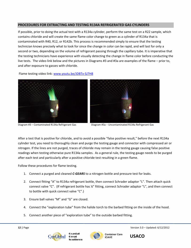
If possible, prior to doing the actual test with a R134a cylinder, perform the same test on a R22 sample, which contains chloride and will create the same flame color change to green as a cylinder of R134a that is contaminated with R40, R12, or R142b. This process is recommended simply to ensure that the testing technician knows precisely what to look for since the change in color can be rapid, and will last for only a second or two, depending on the volume of refrigerant passing through the capillary tube. It is imperative that the testing technicians have experience with visually detecting the change in flame color before conducting the live tests. The video link below and the pictures in Diagrams #3 and #3a are examples of the flame – prior to, and after exposure to gasses with chloride.
Flame testing video link: www.youtu.be/JDBTx‐SJ7H8
Diagram #3 – Contaminated R134a Refrigerant Gas Diagram #3a – Uncontaminated R134a Refrigerant Gas
After a test that is positive for chloride, and to avoid a possible “false positive result,” before the next R134a cylinder test, you need to thoroughly clean and purge the testing gauge and connector with compressed air or nitrogen. If the lines are not purged, traces of chloride may remain in the testing gauge causing false positive readings when testing otherwise pure R134a samples. As a general rule, the testing gauge needs to be purged after each test and particularly after a positive chloride test resulting in a green flame.
Follow these procedures for flame testing.
1. Connect a purged and cleaned C‐GEARS to a nitrogen bottle and pressure test for leaks.
2. Connect fitting “A” to R134a refrigerant bottle, then connect Schrader adaptor “L”. Then attach quick connect valve “C”. (If refrigerant bottle has ¼” fitting, connect Schrader adaptor “L”, and then connect to bottle with quick connect valve “C”.)
3. Ensure ball valves “M” and “G” are closed.
4. Connect the “exploration tube” from the halide torch to the barbed fitting on the inside of the hood.
5. Connect another piece of “exploration tube” to the outside barbed fitting.
13 | Page Version 3.0 – Updated: 6/12/2012
USACO
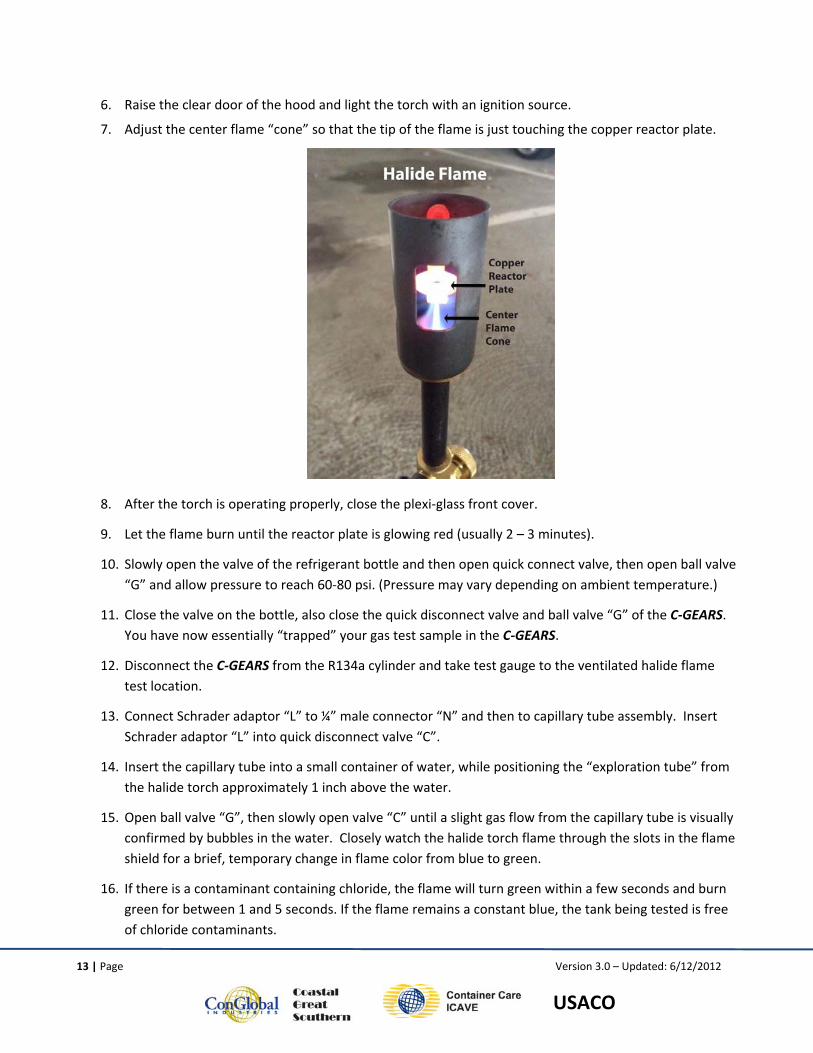
6. Raise the clear door of the hood and light the torch with an ignition source.
7. Adjust the center flame “cone” so that the tip of the flame is just touching the copper reactor plate.
8. After the torch is operating properly, close the plexi‐glass front cover.
9. Let the flame burn until the reactor plate is glowing red (usually 2 – 3 minutes).
10. Slowly open the valve of the refrigerant bottle and then open quick connect valve, then open ball valve “G” and allow pressure to reach 60‐80 psi. (Pressure may vary depending on ambient temperature.)
11. Close the valve on the bottle, also close the quick disconnect valve and ball valve “G” of the C‐GEARS. You have now essentially “trapped” your gas test sample in the C‐GEARS.
12. Disconnect the C‐GEARS from the R134a cylinder and take test gauge to the ventilated halide flame test location.
13. Connect Schrader adaptor “L” to ¼” male connector “N” and then to capillary tube assembly. Insert Schrader adaptor “L” into quick disconnect valve “C”.
14. Insert the capillary tube into a small container of water, while positioning the “exploration tube” from the halide torch approximately 1 inch above the water.
15. Open ball valve “G”, then slowly open valve “C” until a slight gas flow from the capillary tube is visually confirmed by bubbles in the water. Closely watch the halide torch flame through the slots in the flame shield for a brief, temporary change in flame color from blue to green.
16. If there is a contaminant containing chloride, the flame will turn green within a few seconds and burn green for between 1 and 5 seconds. If the flame remains a constant blue, the tank being tested is free of chloride contaminants.
14 | Page Version 3.0 – Updated: 6/12/2012
USACO
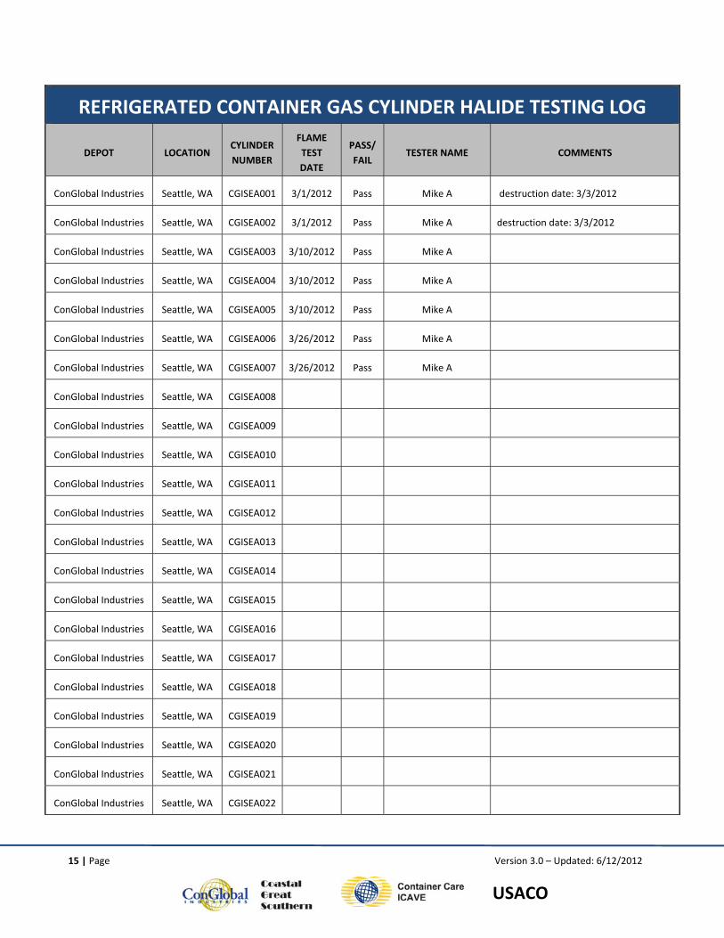
LABELLING AND TRACKING TEST RESULTS
An auditable process for testing gas samples is essential to document which cylinders have been tested to prevent additional contaminated gas from being introduced to refrigerated container machines. When a new gas cylinder is ready to be used for service, a halide test should be performed to determine if the gas has been contaminated. Once the cylinder has been tested, the testing technician will use an indelible marker to mark DIRECTLY ON THE CYLINDER ‐ 1) the depot location, 2) cylinder number, 3) test date, 4) test result and 5) technician signature. This information is then recorded on a log to create an audit trail that can be easily shared with container owners and auditors upon request. An example of the log is attached as reference.
Currently, gas cylinders do not have unique serial numbers that can be used for identification. Therefore, repair facilities need to create a unique number for each cylinder that is tested. At ConGlobal Industries, the cylinder number will adhere to the following format. It starts with a three alpha code representing the depot company name; followed by a three alpha code representing the testing location; and ends with a sequential three number code. Using CGISEA001 as an example, CGI = ConGlobal Industries; SEA = Seattle, Washington; and 001 = sequential number. If a cylinder is not labelled with all 5 pieces of testing information listed above, it should not be used.
After a tank is empty, the valve should be knocked off. Be sure the tank is empty and properly evacuated before knocking off valve! The tank can then be scrapped. Crushing the tank may be required by some recyclers. Check with your local scrap metal recycler for their specific requirement. After destruction, note the destruction date on the Gas Bottle Testing Log Sheet under the comments section.
15 | Page Version 3.0 – Updated: 6/12/2012
USACO
REFRIGERATED CONTAINER GAS CYLINDER HALIDE TESTING LOG
DEPOT LOCATION CYLINDER NUMBER
FLAME TEST DATE
PASS/FAIL
TESTER NAME COMMENTS
ConGlobal Industries Seattle, WA CGISEA001 3/1/2012 Pass Mike A destruction date: 3/3/2012
ConGlobal Industries Seattle, WA CGISEA002 3/1/2012 Pass Mike A destruction date: 3/3/2012
ConGlobal Industries Seattle, WA CGISEA003 3/10/2012 Pass Mike A
ConGlobal Industries Seattle, WA CGISEA004 3/10/2012 Pass Mike A
ConGlobal Industries Seattle, WA CGISEA005 3/10/2012 Pass Mike A
ConGlobal Industries Seattle, WA CGISEA006 3/26/2012 Pass Mike A
ConGlobal Industries Seattle, WA CGISEA007 3/26/2012 Pass Mike A
ConGlobal Industries Seattle, WA CGISEA008
ConGlobal Industries Seattle, WA CGISEA009
ConGlobal Industries Seattle, WA CGISEA010
ConGlobal Industries Seattle, WA CGISEA011
ConGlobal Industries Seattle, WA CGISEA012
ConGlobal Industries Seattle, WA CGISEA013
ConGlobal Industries Seattle, WA CGISEA014
ConGlobal Industries Seattle, WA CGISEA015
ConGlobal Industries Seattle, WA CGISEA016
ConGlobal Industries Seattle, WA CGISEA017
ConGlobal Industries Seattle, WA CGISEA018
ConGlobal Industries Seattle, WA CGISEA019
ConGlobal Industries Seattle, WA CGISEA020
ConGlobal Industries Seattle, WA CGISEA021
ConGlobal Industries Seattle, WA CGISEA022
16 | Page Version 3.0 – Updated: 6/12/2012
USACO
5.0 NEW SAFETY REQUIREMENTS FOR SERVICING R134A REFRIGERATED CONTAINERS
The investigation(s) of the containers that have exploded indicate that one of the possible conditions causing the explosions is the introduction of a “fresh” R134a refrigerant charge into a contaminated system. In an effort to keep our service technicians safe, with immediate effect, any refrigerated container using R134a refrigerant that requires the connection of a manifold gauge set for any reason, including::
• A R134a refrigerant gas charge,
• The evacuation of R134a refrigerant gas for any reason (i.e . system repair), OR
• Simple pressure check.
will first be required to undergo a “Refrigeration gas health and safety check”. This process will entail that a small sample of refrigerant gas be extracted by methods carefully developed by ConGlobal, and field screened / tested by either Halide flame test or by RRA Chloride test tube. The cost for this field screening is minimal and is available to ConGlobal clients upon request.
(A video of the Halide flame test can be viewed at http://youtu.be/JDBTx‐SJ7H8)
The results for all refrigerant samples tested will be communicated to the clients and will be recorded with the ConGlobal service history for the unit. If the refrigerant gas sample “passes” the field screen test, then our service technicians will affix a R134a refrigerant test decal to the unit (see below for more details) and proceed with the normal service routine.
However, any R134a refrigerant gas “failing” the field screen test will be subject to a Gas Chromatography – Mass Spectrometry (GC‐MS) open scan lab test before any further machinery repairs are carried out. The cost to our client for this additional required safety test will not be incurred until approval by the client is received. The detailed results of the GC‐MS open scan will be provided electronically to the container client / owner for their records and will also be kept in the unit service files at ConGlobal.
Note: GC‐MS test results indicating any detectable levels of R40 (methyl chloride), Trimethyl Aluminum (TMA), Tetramethylsilane (TMS) or any other pyrophoric gas or substance will result in the unit being classified as potentially dangerous and all service work will STOP until consultation with the owner regarding neutralization measures are taken and the affected container can be safely returned to service or destroyed.
Consistent with ARI‐700 refrigerant standards, any GC‐MS results indicating > .5% (1/2 of 1%) of other non dangerous contamination, i.e. R142b, R12, R22, etc., will result in the unit being 1) completely evacuated, purged, or cleaned with dry nitrogen, 2) oil removed and replaced, 3) a new filter drier installed, and 4) the system recharged with new R134a refrigerant. After recharging the unit and running it for 30 minutes, another refrigerant gas screen test (Halide or RRA Tube test) will be performed to confirm the effectiveness of the process.
17 | Page Version 3.0 – Updated: 6/12/2012
USACO
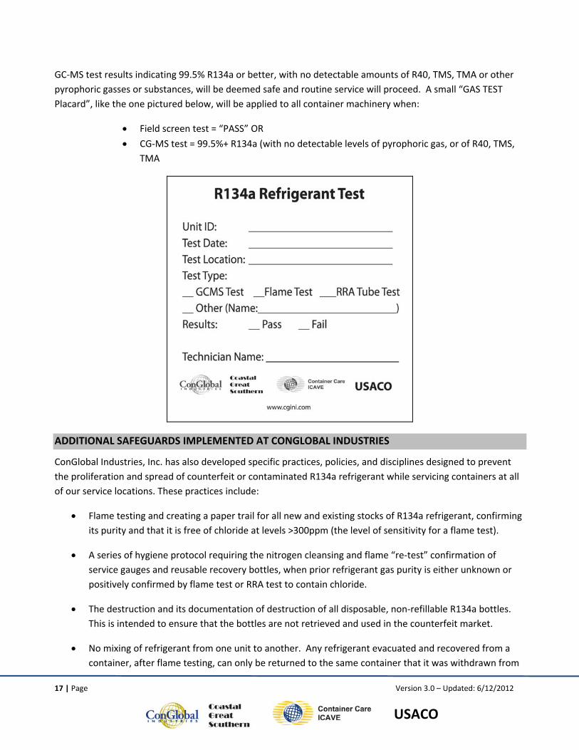
GC‐MS test results indicating 99.5% R134a or better, with no detectable amounts of R40, TMS, TMA or other pyrophoric gasses or substances, will be deemed safe and routine service will proceed. A small “GAS TEST Placard”, like the one pictured below, will be applied to all container machinery when:
• Field screen test = “PASS” OR
• CG‐MS test = 99.5%+ R134a (with no detectable levels of pyrophoric gas, or of R40, TMS, TMA
ADDITIONAL SAFEGUARDS IMPLEMENTED AT CONGLOBAL INDUSTRIES
ConGlobal Industries, Inc. has also developed specific practices, policies, and disciplines designed to prevent the proliferation and spread of counterfeit or contaminated R134a refrigerant while servicing containers at all of our service locations. These practices include:
• Flame testing and creating a paper trail for all new and existing stocks of R134a refrigerant, confirming its purity and that it is free of chloride at levels >300ppm (the level of sensitivity for a flame test).
• A series of hygiene protocol requiring the nitrogen cleansing and flame “re‐test” confirmation of service gauges and reusable recovery bottles, when prior refrigerant gas purity is either unknown or positively confirmed by flame test or RRA test to contain chloride.
• The destruction and its documentation of destruction of all disposable, non‐refillable R134a bottles. This is intended to ensure that the bottles are not retrieved and used in the counterfeit market.
• No mixing of refrigerant from one unit to another. Any refrigerant evacuated and recovered from a container, after flame testing, can only be returned to the same container that it was withdrawn from
18 | Page Version 3.0 – Updated: 6/12/2012
USACO
and will not be mixed with refrigerant from any other unit. If for some reason the refrigerant withdrawn from a unit is not replaced in the same unit, the refrigerant will be recycled, reclaimed or incinerated rather than used in another unit. This policy is intended to include ALL containers in EVERY circumstance including sale and scrap refrigerated containers, where it is common in some repair facilities to evacuate the refrigerant with the specific intent of resale.
• The establishment and implementation of a record keeping system for all R134a refrigerants used to service a refrigerated container that can be traced back to the bottle of origin. When combined with the new bottle testing protocol described earlier, unit specific service records can easily be traced back to a flame tested / purity proven R134a refrigerant source.
• The training of every ConGlobal refrigeration service technician and parts receiving personnel as to the characteristics that might indicate a refrigerant cylinder may be a counterfeited product.
• As a condition of employment at ConGlobal or affiliated companies, every service technician, their supervisors, and facility General Managers will acknowledge receipt of these policies; acknowledge their complete understanding and the intentions of these policies; and pledge to follow the protocol and refrigerant handling procedures. Additionally, this handbook should be included in the refrigeration personnel new hire check list.
19 | Page Version 3.0 – Updated: 6/12/2012
USACO
6.0 CONGLOBAL ‐ GAS EXTRACTION AND ANALYSIS RECOVERY SYSTEM (C‐GEARS)
SAMPLING METHODS
ConGlobal’s refrigeration gas sampling, test methodology, and procedures are described in this document.
1. Sample method to safely extract gas and to field check refrigeration machinery for chlorine contamination.
2. Taking a sample from a refrigeration machine for laboratory analysis – ‘MAI sample tube’.
IMPORTANT PRECAUTIONS
It is advisable for all technicians to consider that a refrigeration machine system might be contaminated before turning the power on and before any attempt is made to take a gas sample.
Currently, the simplest and most reliable test for detecting the presence of chloride contamination is the Halide Flame Test. It should not be used without following detailed instructions and taking suitable precautions. The Halide Flame Test is sensitive to approximately 300 ppm for chloride (0.03%) and it is therefore likely to detect if a system has been contaminated with a ‘chloro‐alkane’ such as R40 or HCFCs such as R22, R12 or R142b.
It should be remembered that the test is for chloride and not a test for the very dangerous gas TMS (Trimethylsilene) or TMA (Trimethylaluminium), which if present, would be a liquid in the crankcase. The melting point of TMA is 15oC. It is remotely possible that even where a Halide Flame Test has not detected the presence of chloride in a gas sample taken from a refrigeration machine, there may still be contamination residues in the compressor that could be hazardous. Technicians should remain vigilant and cautious when working on the refrigeration system.
When refrigeration systems are contaminated with R40, harmful chemicals may have also formed in the system. In some cases, these chemicals may burn spontaneously in air on contact with water. Technicians are advised to wear protective clothing, gloves, eye protection, keeping skin covered as much as possible and to avoid any contaminated chemical coming into contact with the skin or being inhaled.
To date, there have been four instances where compressors have exploded while being worked on. It is suspected that this might have been a result of R134a refrigerant being introduced into the compressor during charging or when the machine power was turned on allowing refrigerant to return to the compressor. Other suspected conditions that many experts suspect may lead to explosions are the introduction of air, oxygen or moisture into a contaminated system. In addition, unusually high compressor temperatures and/or pressures while running should also be of serious concern, and may cause or contribute to a potential explosion.
20 | Page Version 3.0 – Updated: 6/12/2012
USACO
There is a possibility that a contaminated refrigeration system could have a negative pressure relative to the atmosphere when it is not running. This can happen if the refrigeration system was contaminated with a large amount of methyl chloride (R40). The R40 might have been consumed by a chemical reaction with aluminium components in the compressor, thus reducing the percentage of R40 and the latent pressure in the system.
Conversely, the extreme high temperatures and pressures that a compressor can reach while running, if contaminated with certain non 134a refrigerants, (which has been simulated in laboratory conditions) is of particular concern and may also be related to the potential explosion of a refrigeration compressor.
C‐GEARS METHOD TO CHECK REFRIGERATION MACHINERY FOR CHLORIDE CONTAMINATION
This technique is intended to enable service technicians to quickly and safely check a refrigeration machine in a typical repair depot environment for chloride contamination to determine if it is safe to work on the unit.
If a unit is contaminated, it is possible that the gas in the refrigeration system may violently react, smoke, combust or even explode with the introduction of air, water, fresh R134a, or an electrical spark.
• It is very important to ensure that no air, moisture, or water can enter into the system while extracting gas. Similarly it is important not to allow any system refrigerant to leak into the atmosphere while extracting gas for sampling & testing purposes.
• All connections must be completely dry.
• Prior to the extraction process, confirm the unit is unplugged before proceeding.
On some systems that are contaminated, the sight glass may be a dark grey or brown color and not easy to see into. If this is the case, extra caution should be taken when removing samples.
PREPARATION
Ensure all connections are clean and dry on both the C‐GEARS extraction device and refrigeration machinery.
• Position the refrigeration unit to be tested from the flame source.
• Be sure to discharge any static electricity by touching the unit frame immediately prior to extracting the gas sample.
• Enforce a non‐smoking zone of at least 25’.
• Provide a Class C (dry powder) and Class D fire extinguisher in the immediate work area.
• Technician should always wear PPE safety glasses and face shield, gloves, and high visibility vest.
EQUIPMENT
• C‐GEARS extraction device
• Vacuum pump
• Bottle of dry nitrogen with regulator
21 | Page Version 3.0 – Updated: 6/12/2012
USACO
• HFC R134a quick connectors
• Spanner wrench
• MAI Gas sample tube with PH paper (available at McCampbell Analytical – Pittsbug, CA ‐ www.mccampbell.com)
• Halide flame torch and CGI ventilation hood
• Safety glasses or Face Shield
• Protective Gloves
22 | Page Version 3.0 – Updated: 6/12/2012
USACO
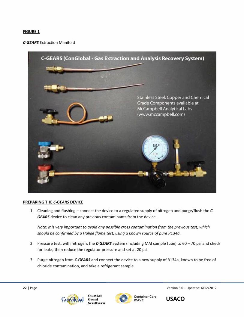
FIGURE 1
C‐GEARS Extraction Manifold
PREPARING THE C‐GEARS DEVICE
1. Cleaning and flushing – connect the device to a regulated supply of nitrogen and purge/flush the C‐GEARS device to clean any previous contaminants from the device.
Note: it is very important to avoid any possible cross contamination from the previous test, which should be confirmed by a Halide flame test, using a known source of pure R134a.
2. Pressure test, with nitrogen, the C‐GEARS system (including MAI sample tube) to 60 – 70 psi and check for leaks, then reduce the regulator pressure and set at 20 psi.
3. Purge nitrogen from C‐GEARS and connect the device to a new supply of R134a, known to be free of chloride contamination, and take a refrigerant sample.
23 | Page Version 3.0 – Updated: 6/12/2012
USACO
4. Halide flame test this sample of “known clean R134a” to insure there is no chloride present in the C‐GEARS device.
5. Check the PH Paper to confirm neutral PH level of 4 to 8 on the color scale.
6. Evacuate C–GEARS into a vacuum of 29‐30 in/HG. After shutting vacuum pump off, and closing the quick connect valve, confirm vacuum is maintained for 30 seconds, confirming no leaks in the C‐GEARS device.
TAKING SAMPLES FROM REFRIGERATION MACHINE
SAMPLE PORTS
Gas samples can be taken from either the High Pressure (HP) or Low Pressure (LP) side of an idle unit that is disconnected from a power source. The recommended access port is generally described as a service port located as far from the compressor as possible – both its physical location in proximity to the compressor and the farthest “piping distance” from the compressor. This recommendation is intended to allow service technicians to be as far from the compressor as possible (physical distance) while affording the least likely chance of encountering Trimethyl Aluminium (TMA), which may have formed in the compressor and migrated to other parts of the refrigeration system. In the case of a Carrier NT machine the recommended access port is the King Valve.
SAMPLING PROCESS
• After properly cleaning, pressure testing, and leak checking by vacuum, the gas sampling process can begin.
• The C‐GEARS device should be in a 29‐30 in/HG vacuum.
• Choose the refrigeration unit sampling port based on the criteria above (sampling ports).
1. Ensure access port is clean and dry.
2. With the quick connect and service valves closed (back seated) attach the quick connect valve of the C‐GEARS to the service port.
NOTE: IMPORTANT INFORMATION RELATED TO SCHRADER VALVES
A portion of intermodal refrigeration units are equipped with Refrigeration Access Valves, commonly referred to as Schrader Valves, which is one manufacturer of these types of valves (see photo below).These valves can be found on the discharge service valve, suction service valve, and at various points in the refrigerant plumbing lines.
24 | Page Version 3.0 – Updated: 6/12/2012
USACO
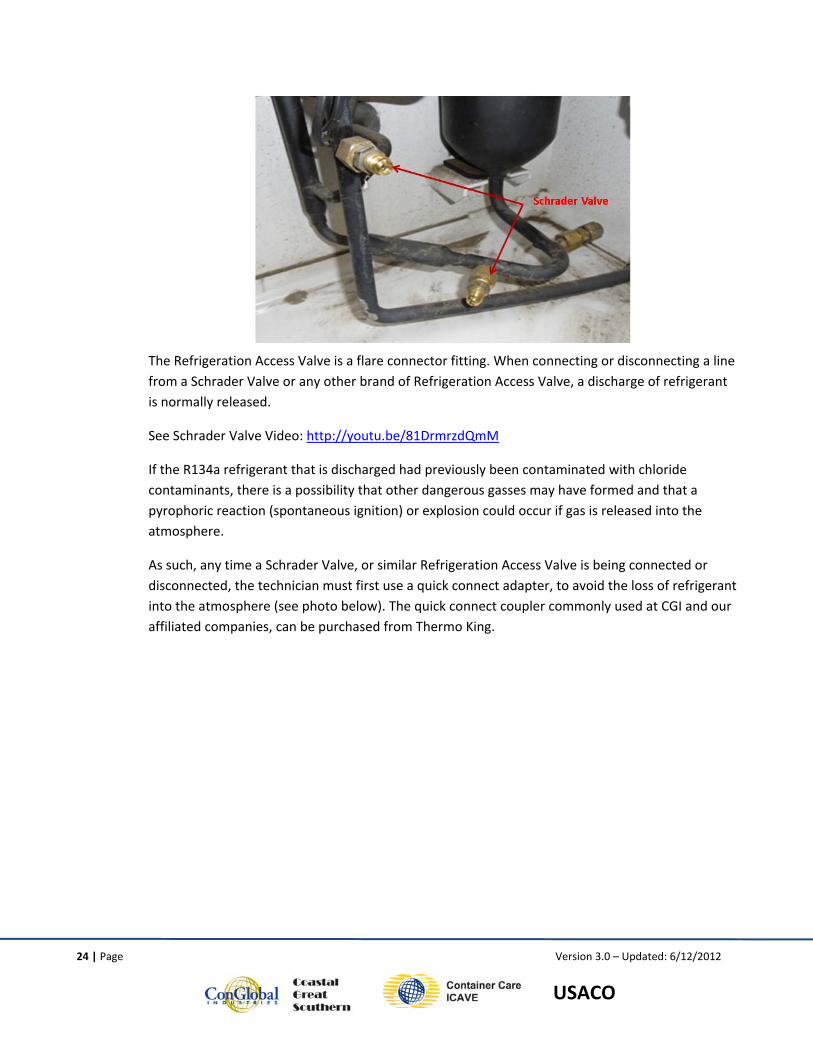
The Refrigeration Access Valve is a flare connector fitting. When connecting or disconnecting a line from a Schrader Valve or any other brand of Refrigeration Access Valve, a discharge of refrigerant is normally released.
See Schrader Valve Video: http://youtu.be/81DrmrzdQmM
If the R134a refrigerant that is discharged had previously been contaminated with chloride contaminants, there is a possibility that other dangerous gasses may have formed and that a pyrophoric reaction (spontaneous ignition) or explosion could occur if gas is released into the atmosphere.
As such, any time a Schrader Valve, or similar Refrigeration Access Valve is being connected or disconnected, the technician must first use a quick connect adapter, to avoid the loss of refrigerant into the atmosphere (see photo below). The quick connect coupler commonly used at CGI and our affiliated companies, can be purchased from Thermo King.
25 | Page Version 3.0 – Updated: 6/12/2012
USACO
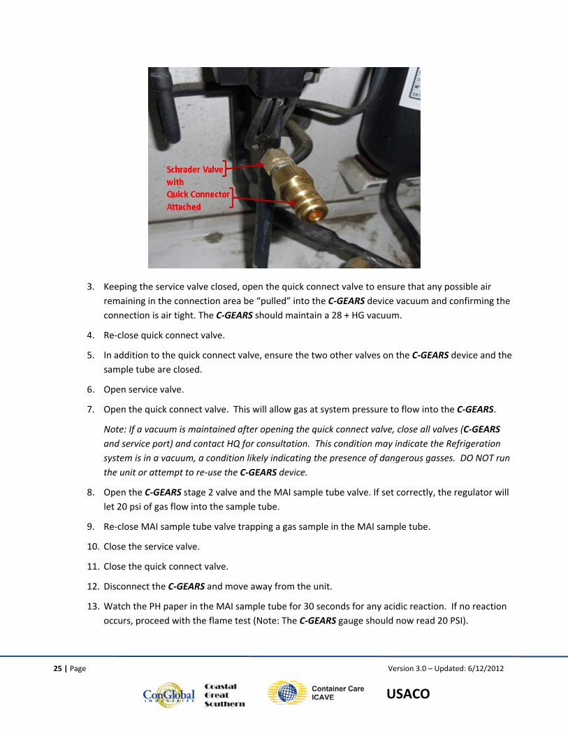
3. Keeping the service valve closed, open the quick connect valve to ensure that any possible air remaining in the connection area be “pulled” into the C‐GEARS device vacuum and confirming the connection is air tight. The C‐GEARS should maintain a 28 + HG vacuum.
4. Re‐close quick connect valve.
5. In addition to the quick connect valve, ensure the two other valves on the C‐GEARS device and the sample tube are closed.
6. Open service valve.
7. Open the quick connect valve. This will allow gas at system pressure to flow into the C‐GEARS.
Note: If a vacuum is maintained after opening the quick connect valve, close all valves (C‐GEARS and service port) and contact HQ for consultation. This condition may indicate the Refrigeration system is in a vacuum, a condition likely indicating the presence of dangerous gasses. DO NOT run the unit or attempt to re‐use the C‐GEARS device.
8. Open the C‐GEARS stage 2 valve and the MAI sample tube valve. If set correctly, the regulator will let 20 psi of gas flow into the sample tube.
9. Re‐close MAI sample tube valve trapping a gas sample in the MAI sample tube.
10. Close the service valve.
11. Close the quick connect valve.
12. Disconnect the C‐GEARS and move away from the unit.
13. Watch the PH paper in the MAI sample tube for 30 seconds for any acidic reaction. If no reaction occurs, proceed with the flame test (Note: The C‐GEARS gauge should now read 20 PSI).
26 | Page Version 3.0 – Updated: 6/12/2012
USACO
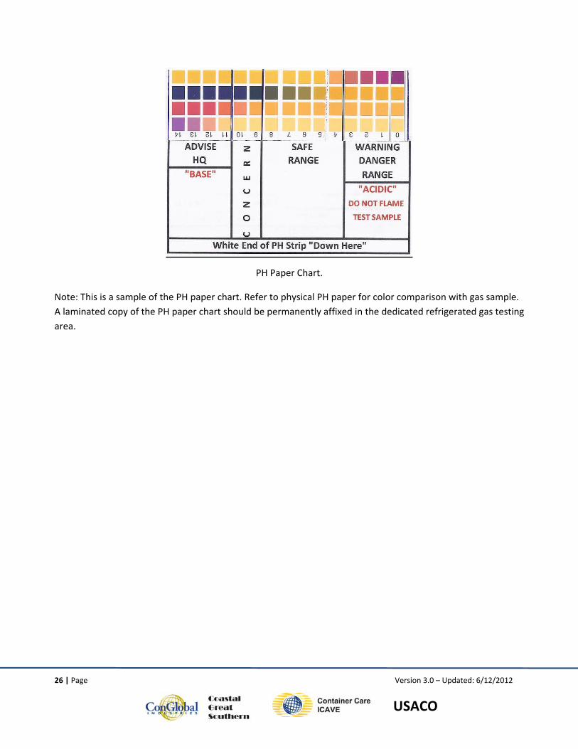
PH Paper Chart.
Note: This is a sample of the PH paper chart. Refer to physical PH paper for color comparison with gas sample. A laminated copy of the PH paper chart should be permanently affixed in the dedicated refrigerated gas testing area.
27 | Page Version 3.0 – Updated: 6/12/2012
USACO
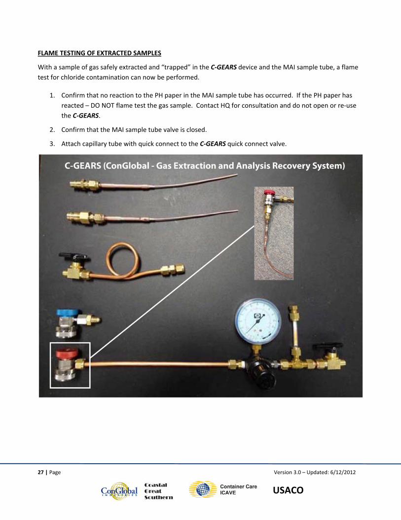
FLAME TESTING OF EXTRACTED SAMPLES
With a sample of gas safely extracted and “trapped” in the C‐GEARS device and the MAI sample tube, a flame test for chloride contamination can now be performed.
1. Confirm that no reaction to the PH paper in the MAI sample tube has occurred. If the PH paper has reacted – DO NOT flame test the gas sample. Contact HQ for consultation and do not open or re‐use the C‐GEARS.
2. Confirm that the MAI sample tube valve is closed.
3. Attach capillary tube with quick connect to the C‐GEARS quick connect valve.
28 | Page Version 3.0 – Updated: 6/12/2012
USACO
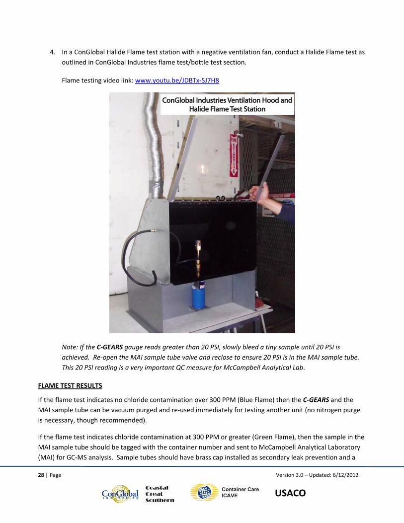
4. In a ConGlobal Halide Flame test station with a negative ventilation fan, conduct a Halide Flame test as outlined in ConGlobal Industries flame test/bottle test section.
Flame testing video link: www.youtu.be/JDBTx‐SJ7H8
Note: If the C‐GEARS gauge reads greater than 20 PSI, slowly bleed a tiny sample until 20 PSI is achieved. Re‐open the MAI sample tube valve and reclose to ensure 20 PSI is in the MAI sample tube. This 20 PSI reading is a very important QC measure for McCampbell Analytical Lab.
FLAME TEST RESULTS
If the flame test indicates no chloride contamination over 300 PPM (Blue Flame) then the C‐GEARS and the MAI sample tube can be vacuum purged and re‐used immediately for testing another unit (no nitrogen purge is necessary, though recommended).
If the flame test indicates chloride contamination at 300 PPM or greater (Green Flame), then the sample in the MAI sample tube should be tagged with the container number and sent to McCampbell Analytical Laboratory (MAI) for GC‐MS analysis. Sample tubes should have brass cap installed as secondary leak prevention and a
29 | Page Version 3.0 – Updated: 6/12/2012
USACO
chain of custody document should accompany each sample (multiple samples can be included on a single COC form.) Sample tubes should be placed in a sealable plastic bag (as added leak surety) and be safely packaged and sent via overnight (Fed EX or DHL) to McCampbell Analytical in Pittsburg, Ca.
Note: McCampbell Analytical will clean, verify integrity, and return sample tubes to CGI for reuse, after each gas analysis.
CLEANING THE C‐GEARS
After any “failed” flame test (Green Flame) it is critical that the C‐GEARS be thoroughly cleaned and its chloride free condition be confirmed prior to re‐using. This process will generally take longer and be more difficult than imagined. Experience indicates that the cleaning difficulty will depend on the type and amount of chloride contamination. Minor contamination can generally be cleaned with two minutes of nitrogen purging at high pressure and three minutes of vacuum cleaning, repeating each step twice. More severe contamination will take more effort.
After cleaning the C‐GEARS, flame test a “known clean” sample of R134a to ensure the device is chloride free and ready for re‐use with no possibility of a false positive result.
30 | Page Version 3.0 – Updated: 6/12/2012
USACO
7.0 EMPLOYEE ACKNOWLEDGMENT
I have read and fully understand the information, policies and procedures, and instructions outlined in the Refrigeration Technician Handbook.
I fully understand all the specific issues related to receiving, handling, start up, bottle testing, gas handling, and gas extraction methodologies referenced in the handbook.
I agree that if I have any question regarding these policies, procedures, and instructions, I will immediately ask my immediate supervisor for advice or instruction.
I fully understand the importance of following all policies and procedure related to refrigeration service work and agrees to not circumvent any policy, procedure or instruction found in the handbook.
I acknowledge I have been fully instructed and trained in the new procedures outlined in the handbook, and further acknowledge I understand those policies and procedures.
____________________________________ __________________________________________
Employee’s Name (Print) Employee’s Signature
____________________________________ ___________________________________________
Location Today’s Date
___________________________________ ____________________________________________
Supervisor’s Name Supervisor’s Signature
____________________________________ ____________________________________________
General Manager’s Name General Manager’s Signature


![THERMODYNAMIC ANALYSIS OF R134A – DMAC VAPOR ABSORPTION ... · PDF fileand R22 based vapor absorption refrigeration systems was performed by Songara et al. [5] ... No literature](https://img.pdfslide.us/doc/110x75/5aab67547f8b9ac55c8bcf2d/thermodynamic-analysis-of-r134a-dmac-vapor-absorption-r22-based-vapor-absorption.jpg)