Embed Size (px)
Citation preview
Product Version Page V1.0.0
R100 Series Industrial Router User Manual Product Name:R100 Series Total:83
R100 Series Industrial Router
User Manual
R100 Series 2G/3G/4G Cellular Dual-SIM Router 1x WAN, 4 x LAN, 1 x RS232/RS485
Model No. Description
R100-L 4G LTE FDD Router
R100-LT 4G LTE TDD Router
R100-H 3G HSPA+/HSUPA/WCDMA/UMTS Router
R100-EV CDMA2000 EVDO Router
R100-E EDGE Router
R100-G GSM/GPRS Router
Yifan Industry Limited. Add:Room 618, No.12,Gaodian Road, HuLi District,
XiaMen, China Zip Code: 361000
Tel:+86 592-6101492
Fax:+86 592-5222813
http://www.yifanwireless.com

R100 Series Industrial Router User Manual
Files Revised Record
Date Version Remark Author
2016.05.24 V1.0.0 Initial version Cm.chen/WT
R100 Series Industrial Router User Manual
R100 Series Industrial Router User Manual
CCoonntteennttss Chapter 1 Brief Introduction of Product ........................................................................................... 6
1.1 General............................................................................................................................. 6 1.2 Features and Benefits ....................................................................................................... 7 1.3 Working Principle ............................................................................................................ 8 1.4 Specifications................................................................................................................... 8
Chapter 2 Installation Introduction ................................................................................................. 12 2.1 General........................................................................................................................... 12 2.2 Encasement List ............................................................................................................. 12 2.3 Installation and Cable Connection ................................................................................. 12 2.4 Power ............................................................................................................................. 16 2.5 Indicator Lights Introduction ......................................................................................... 16 2.6 Reset Button Introduction .............................................................................................. 17 2.7 Flank Interface .................................................................................................................. 17
Chapter 3 Configuration and Management ..................................................................................... 18 3.1 Configuration Connection.............................................................................................. 18 3.2 Access the Configuration Web Page .............................................................................. 18 3.3 Management and configuration ..................................................................................... 20
3.3.1 Setting .................................................................................................................... 20 3.3.9.1 Basic Setting ............................................................................................... 20 3.3.9.2 Dynamic DNS............................................................................................. 25 3.3.9.3 Clone MAC Address ................................................................................... 26 3.3.9.4 Advanced Router......................................................................................... 27 3.3.9.5 VLANs........................................................................................................ 28 3.3.9.6 Networking ................................................................................................. 29
3.3.2 Wireless.................................................................................................................. 32 3.3.2.1 Basic Settings.............................................................................................. 32 3.3.2.2 Wireless Security......................................................................................... 34
3.3.3 Services .................................................................................................................. 35 3.3.4.1 Services ....................................................................................................... 35
3.3.4 VPN ....................................................................................................................... 38 3.3.6.1 PPTP ........................................................................................................... 38 3.3.6.2 L2TP ........................................................................................................... 40 3.3.6.3 OPENVPN .................................................................................................. 41 3.3.6.4 IPSEC.......................................................................................................... 45 3.3.6.5 GRE ............................................................................................................ 47
3.3.5 Security .................................................................................................................. 49 3.3.5.1 Firewall ....................................................................................................... 49
3.3.6 Access Restrictions ................................................................................................ 51 3.3.6.1 WAN Access ............................................................................................... 51 3.3.6.2 URL Filter ................................................................................................... 54 3.3.6.3 Packet Filter ................................................................................................ 54
3.3.7 NAT........................................................................................................................ 55

R100 Series Industrial Router User Manual
3.3.1.1 Port Forwarding .......................................................................................... 55 3.3.1.2 Port Range Forward .................................................................................... 56 3.3.1.3 DMZ............................................................................................................ 57
3.3.8 QoS Setting ............................................................................................................ 57 3.3.8.1 Basic............................................................................................................ 57 3.3.8.2 Classify ....................................................................................................... 58
3.3.9 Applications ........................................................................................................... 58 3.3.2.1 Serial Applications ...................................................................................... 58
3.3.10 Administration ..................................................................................................... 60 3.3.10.1 Management.............................................................................................. 60 3.3.10.2 Keep Alive ................................................................................................ 62 3.3.10.3 Commands ................................................................................................ 63 3.3.10.4 Factory Defaults........................................................................................ 63 3.3.10.5 Firmware Upgrade .................................................................................... 64 3.3.10.6 Backup ...................................................................................................... 64
3.3.11 Status .................................................................................................................... 65 3.3.11.1 Router........................................................................................................ 65 3.3.11.2 WAN.......................................................................................................... 67 3.3.11.3 LAN .......................................................................................................... 69 3.3.11.4 Wireless..................................................................................................... 71 3.3.11.5 Bandwidth ................................................................................................. 73 3.3.11.6 Sys-Info..................................................................................................... 75
Appendix......................................................................................................................................... 77
R100 Series Router User Manual
Chapter 1 Brief Introduction of Product
1.1 General
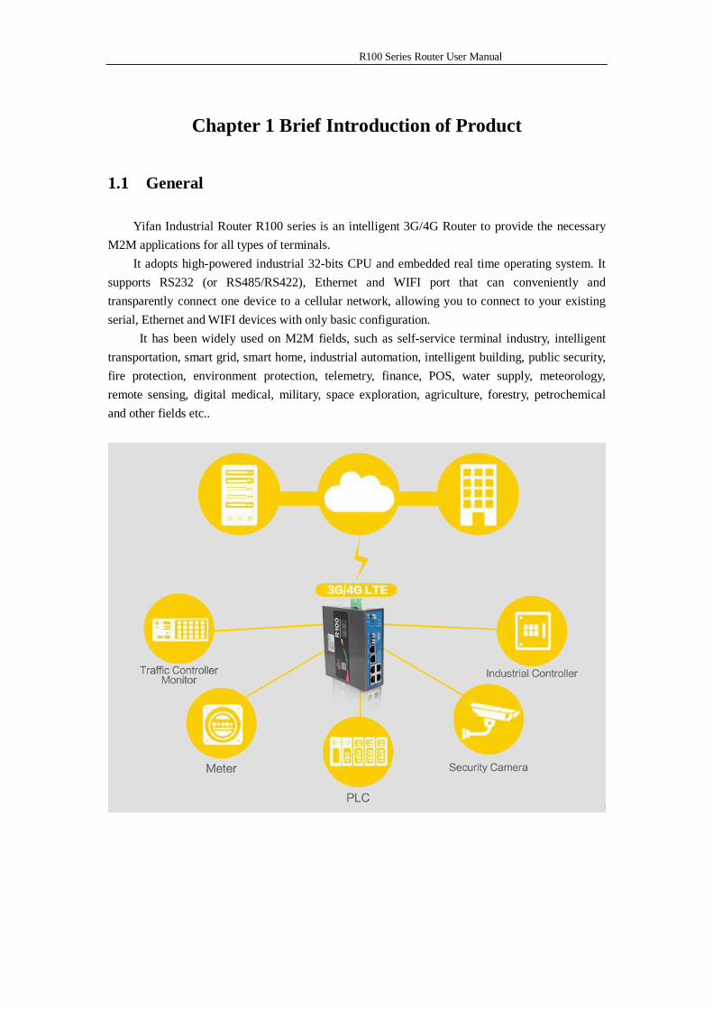
Yifan Industrial Router R100 series is an intelligent 3G/4G Router to provide the necessary M2M applications for all types of terminals.
It adopts high-powered industrial 32-bits CPU and embedded real time operating system. It supports RS232 (or RS485/RS422), Ethernet and WIFI port that can conveniently and transparently connect one device to a cellular network, allowing you to connect to your existing serial, Ethernet and WIFI devices with only basic configuration.
It has been widely used on M2M fields, such as self-service terminal industry, intelligent transportation, smart grid, smart home, industrial automation, intelligent building, public security, fire protection, environment protection, telemetry, finance, POS, water supply, meteorology, remote sensing, digital medical, military, space exploration, agriculture, forestry, petrochemical and other fields etc..
R100 Series Router User Manual
1.2 Features and Benefits
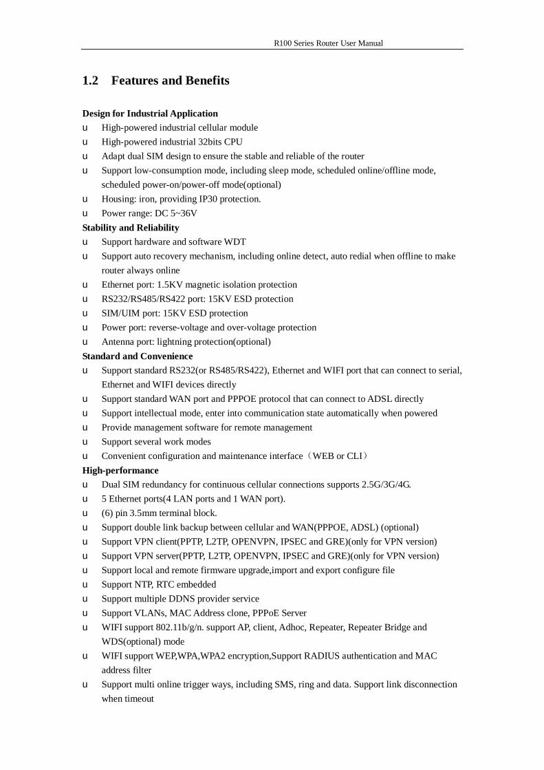
Design for Industrial Application u High-powered industrial cellular module u High-powered industrial 32bits CPU u Adapt dual SIM design to ensure the stable and reliable of the router u Support low-consumption mode, including sleep mode, scheduled online/offline mode,
scheduled power-on/power-off mode(optional) u Housing: iron, providing IP30 protection. u Power range: DC 5~36V Stability and Reliability u Support hardware and software WDT u Support auto recovery mechanism, including online detect, auto redial when offline to make
router always online u Ethernet port: 1.5KV magnetic isolation protection u RS232/RS485/RS422 port: 15KV ESD protection u SIM/UIM port: 15KV ESD protection u Power port: reverse-voltage and over-voltage protection u Antenna port: lightning protection(optional) Standard and Convenience u Support standard RS232(or RS485/RS422), Ethernet and WIFI port that can connect to serial,
Ethernet and WIFI devices directly u Support standard WAN port and PPPOE protocol that can connect to ADSL directly u Support intellectual mode, enter into communication state automatically when powered u Provide management software for remote management u Support several work modes u Convenient configuration and maintenance interface(WEB or CLI) High-performance u Dual SIM redundancy for continuous cellular connections supports 2.5G/3G/4G. u 5 Ethernet ports(4 LAN ports and 1 WAN port). u (6) pin 3.5mm terminal block. u Support double link backup between cellular and WAN(PPPOE, ADSL) (optional) u Support VPN client(PPTP, L2TP, OPENVPN, IPSEC and GRE)(only for VPN version) u Support VPN server(PPTP, L2TP, OPENVPN, IPSEC and GRE)(only for VPN version) u Support local and remote firmware upgrade,import and export configure file u Support NTP, RTC embedded u Support multiple DDNS provider service u Support VLANs, MAC Address clone, PPPoE Server u WIFI support 802.11b/g/n. support AP, client, Adhoc, Repeater, Repeater Bridge and
WDS(optional) mode u WIFI support WEP,WPA,WPA2 encryption,Support RADIUS authentication and MAC
address filter u Support multi online trigger ways, including SMS, ring and data. Support link disconnection
when timeout
R100 Series Router User Manual
u Support APN/VPDN u Support DHCP server and client, firewall, NAT, DMZ host , URL block, QoS, ttraff,statistics,
real time link speed statistics etc u Full protocol support , such as TCP/IP, UDP, ICMP, SMTP, HTTP, POP3, OICQ, TELNET,
FTP, SNMP, SSHD, etc u Schedule Reboot, Schedule Online and Offline,etc u Supports Yifan Cloud Platform (Centralized M2M management platform, to remote monitor,
remote configure, update firmware etc.).
1.3 Working Principle
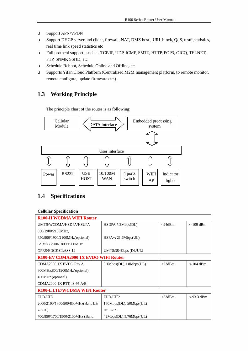
The principle chart of the router is as following:
1.4 Specifications
Cellular Specification R100-H WCDMA WIFI Router
UMTS/WCDMA/HSDPA/HSUPA
850/1900/2100MHz,
850/900/1900/2100MHz(optional)
GSM850/900/1800/1900MHz
GPRS/EDGE CLASS 12
HSDPA:7.2Mbps(DL)
HSPA+: 21.6Mbps(UL)
UMTS:384Kbps (DL/UL)
<24dBm <-109 dBm
R100-EV CDMA2000 1X EVDO WIFI Router
CDMA2000 1X EVDO Rev A
800MHz,800/1900MHz(optional)
450MHz (optional)
CDMA2000 1X RTT, IS-95 A/B
3.1Mbps(DL),1.8Mbps(UL) <23dBm <-104 dBm
R100-L LTE/WCDMA WIFI Router
FDD-LTE
2600/2100/1800/900/800MHz(Band1/3/
7/8/20)
700/850/1700/1900/2100MHz (Band
FDD-LTE:
150Mbps(DL), 50Mbps(UL)
HSPA+:
42Mbps(DL),5.76Mbps(UL)
<23dBm <-93.3 dBm
Embedded processing system
Cellular Module
Power RS232 Indicator lights
DATA Interface
User interface
4 ports switch
WIFI AP
10/100M WAN
USB HOST
Embedded processing system
Cellular Module
Indicator lights
DATA Interface
User interface
WIFI AP
R100 Series Router User Manual
2/4/5/13/17/25)(Optional)
DC-HSPA+/HSPA+/HSDPA/HSUPA/W
CDMA/UMTS
2100/1900/900/850/800MHz(Band
1/2/5/6/8)
EDGE/GPRS/GSM
850/900/1800/1900MHz
HSUPA: 5.76Mbps(UL)
HSDPA: 7.2Mbps(DL)
UMTS:
384Kbps(DL), 384Kbps(UL)
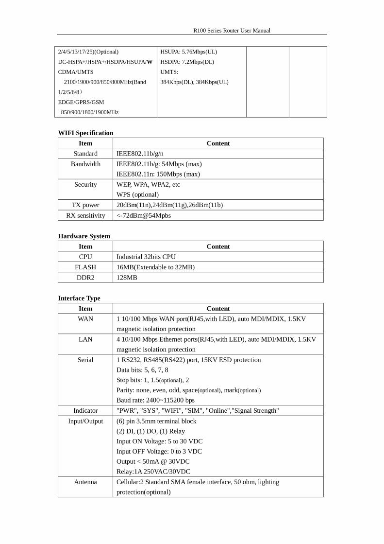
WIFI Specification
Item Content Standard IEEE802.11b/g/n
Bandwidth IEEE802.11b/g: 54Mbps (max) IEEE802.11n: 150Mbps (max)
Security WEP, WPA, WPA2, etc WPS (optional)
TX power 20dBm(11n),24dBm(11g),26dBm(11b)
RX sensitivity <-72dBm@54Mpbs Hardware System
Item Content CPU Industrial 32bits CPU
FLASH 16MB(Extendable to 32MB) DDR2 128MB
Interface Type
Item Content WAN 1 10/100 Mbps WAN port(RJ45,with LED), auto MDI/MDIX, 1.5KV
magnetic isolation protection LAN 4 10/100 Mbps Ethernet ports(RJ45,with LED), auto MDI/MDIX, 1.5KV
magnetic isolation protection Serial 1 RS232, RS485(RS422) port, 15KV ESD protection
Data bits: 5, 6, 7, 8 Stop bits: 1, 1.5(optional), 2 Parity: none, even, odd, space(optional), mark(optional) Baud rate: 2400~115200 bps
Indicator "PWR", "SYS", "WIFI", "SIM", "Online","Signal Strength" Input/Output (6) pin 3.5mm terminal block
(2) DI, (1) DO, (1) Relay Input ON Voltage: 5 to 30 VDC Input OFF Voltage: 0 to 3 VDC Output < 50mA @ 30VDC Relay:1A 250VAC/30VDC
Antenna Cellular:2 Standard SMA female interface, 50 ohm, lighting protection(optional)
R100 Series Router User Manual
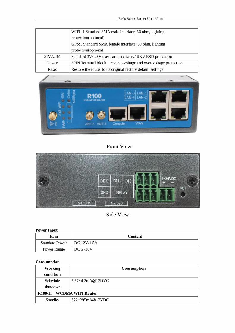
WIFI: 1 Standard SMA male interface, 50 ohm, lighting protection(optional) GPS:1 Standard SMA female interface, 50 ohm, lighting protection(optional)
SIM/UIM Standard 3V/1.8V user card interface, 15KV ESD protection Power 2PIN Terminal block reverse-voltage and over-voltage protection Reset Restore the router to its original factory default settings
Front View
Side View Power Input
Item Content Standard Power DC 12V/1.5A Power Range DC 5~36V
Consumption
Working condition
Consumption
Schedule shutdown
2.57~4.2mA@12DVC
R100-H WCDMA WIFI Router Standby 272~295mA@12VDC
R100 Series Router User Manual
Communication 283~360mA@12VDC R100-EV CDMA2000 1X EVDO WIFI Router
Standby 268~293mA@12VDC Communication 279~355mA@12VDC
R100-L LTE/WCDMA WIFI Router Standby 280~330mA@12VDC
Communication 325~562mA@12VDC Physical Characteristics
Item Content Housing Iron, providing IP30 protection
Dimensions 134.8x115.7x45 mm Weight 520 g
Environmental Limits
Item Content Operating
Temperature -35~+75ºC(-31~+167℉)
Storage Temperature
-40~+85ºC(-40~+185℉)
Operating Humidity
95% (Non-condensing)
R100 Series Router User Manual
Chapter 2 Installation Introduction
2.1 General
The router must be installed correctly to make it work properly. Warning: Forbid to install the router when powered!
2.2 Encasement List
Name Quantity Remark Router host 1 Cellular antenna (Male SMA) 2 WIFI antenna (Female SMA) 1 GPS antenna(Male SMA) 1 optional Network cable 1 Console cable 1 optional RS485 Console cable 1 optional Power adapter 1
Manual CD 1 Certification card 1 Maintenance card 1
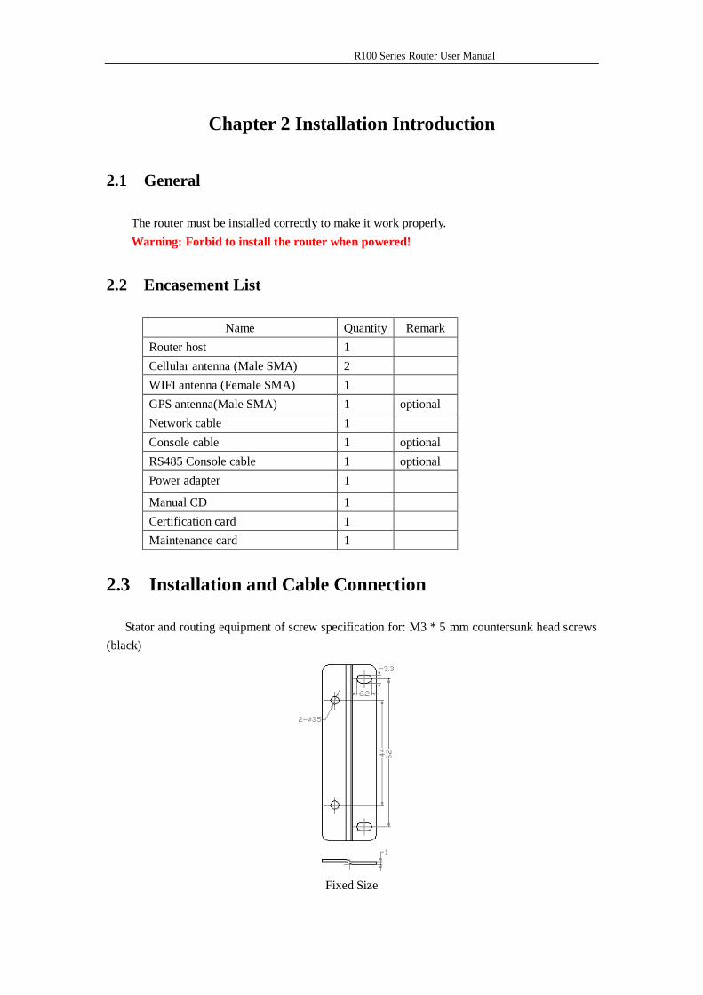
2.3 Installation and Cable Connection
Stator and routing equipment of screw specification for: M3 * 5 mm countersunk head screws (black)
Fixed Size
R100 Series Router User Manual
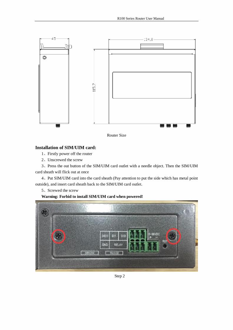
Router Size
Installation of SIM/UIM card:
1、Firstly power off the router 2、Unscrewed the screw 3、Press the out button of the SIM/UIM card outlet with a needle object. Then the SIM/UIM
card sheath will flick out at once 4、Put SIM/UIM card into the card sheath (Pay attention to put the side which has metal point
outside), and insert card sheath back to the SIM/UIM card outlet. 5、Screwed the screw Warning: Forbid to install SIM/UIM card when powered!
Step 2
R100 Series Router User Manual
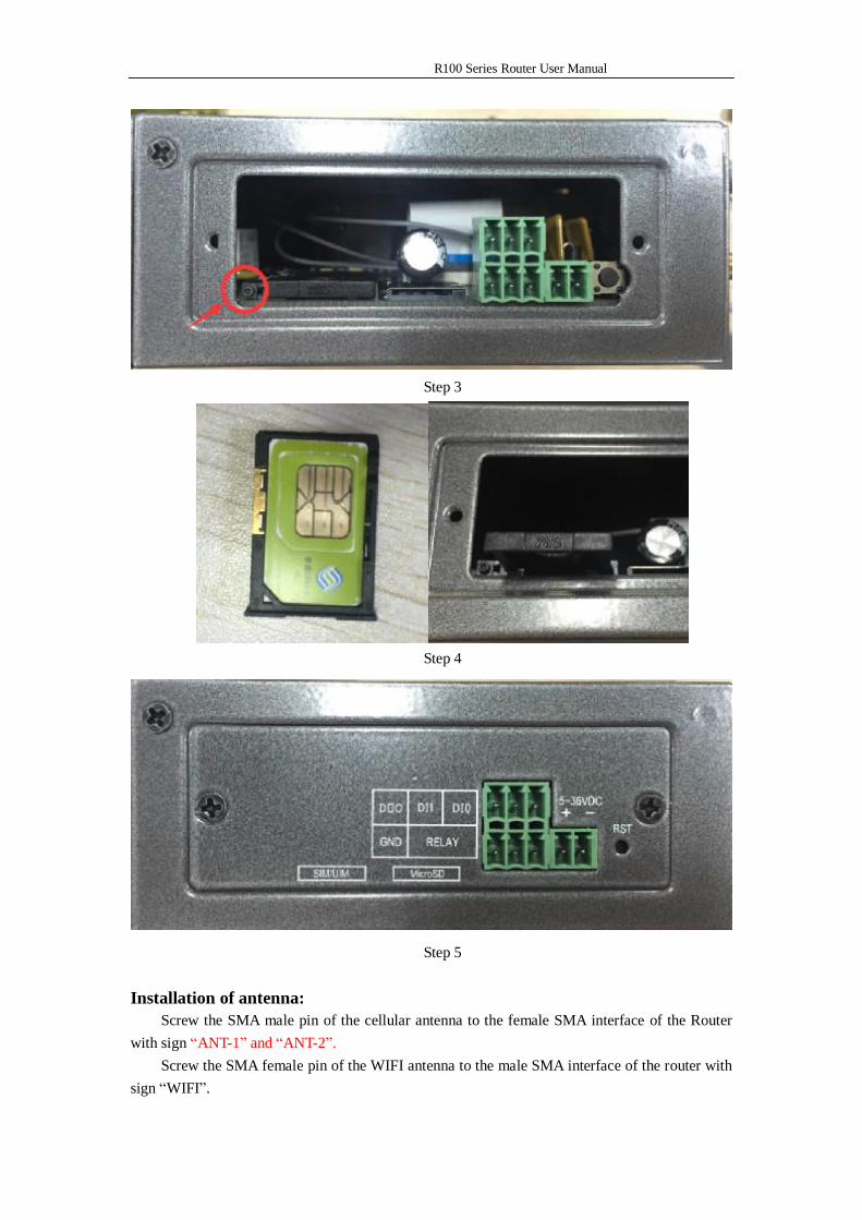
Step 3
Step 4
Step 5
Installation of antenna: Screw the SMA male pin of the cellular antenna to the female SMA interface of the Router
with sign “ANT-1” and “ANT-2”. Screw the SMA female pin of the WIFI antenna to the male SMA interface of the router with
sign “WIFI”.
R100 Series Router User Manual
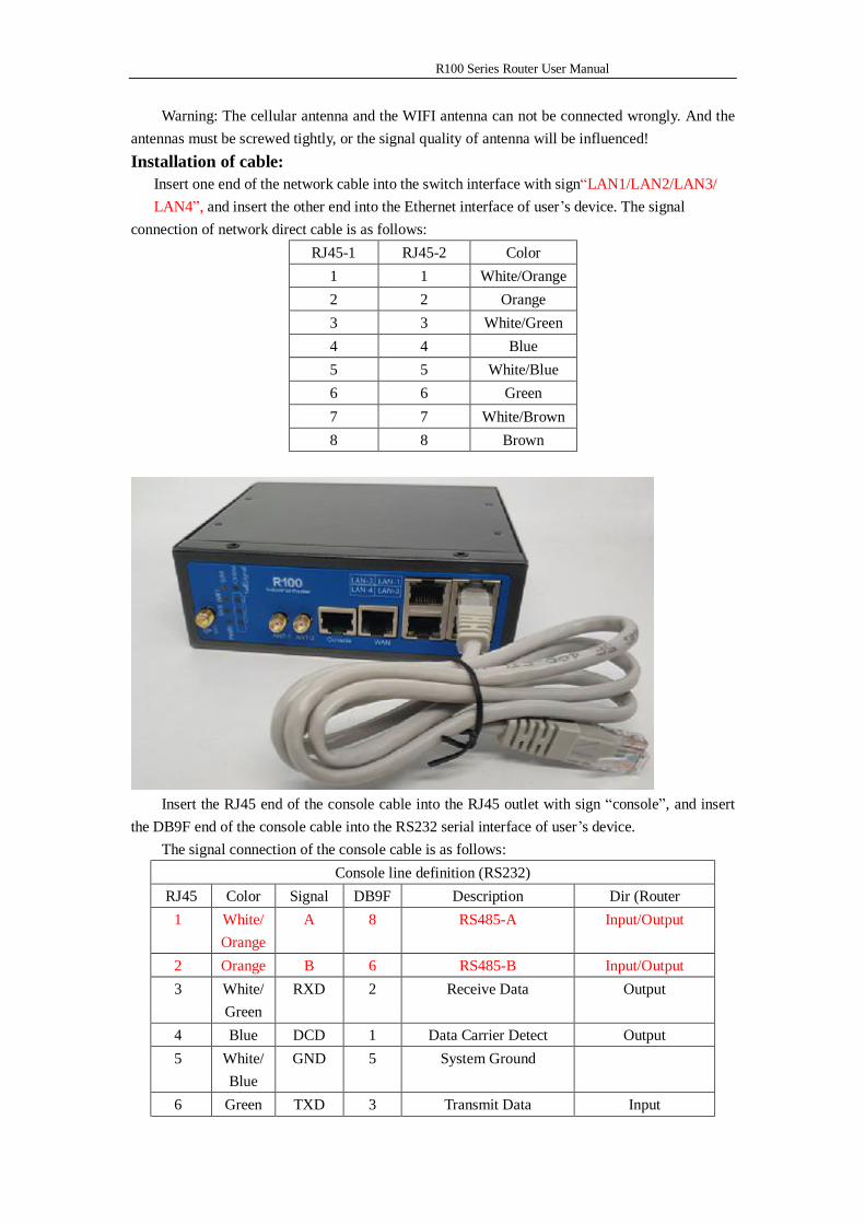
Warning: The cellular antenna and the WIFI antenna can not be connected wrongly. And the antennas must be screwed tightly, or the signal quality of antenna will be influenced! Installation of cable:
Insert one end of the network cable into the switch interface with sign“LAN1/LAN2/LAN3/ LAN4”, and insert the other end into the Ethernet interface of user’s device. The signal
connection of network direct cable is as follows: RJ45-1 RJ45-2 Color
1 1 White/Orange 2 2 Orange 3 3 White/Green 4 4 Blue 5 5 White/Blue 6 6 Green 7 7 White/Brown 8 8 Brown
Insert the RJ45 end of the console cable into the RJ45 outlet with sign “console”, and insert
the DB9F end of the console cable into the RS232 serial interface of user’s device. The signal connection of the console cable is as follows:
Console line definition (RS232) RJ45 Color Signal DB9F Description Dir (Router
1 White/Orange
A 8 RS485-A Input/Output
2 Orange B 6 RS485-B Input/Output 3 White/
Green RXD 2 Receive Data Output
4 Blue DCD 1 Data Carrier Detect Output 5 White/
Blue GND 5 System Ground
6 Green TXD 3 Transmit Data Input
R100 Series Router User Manual
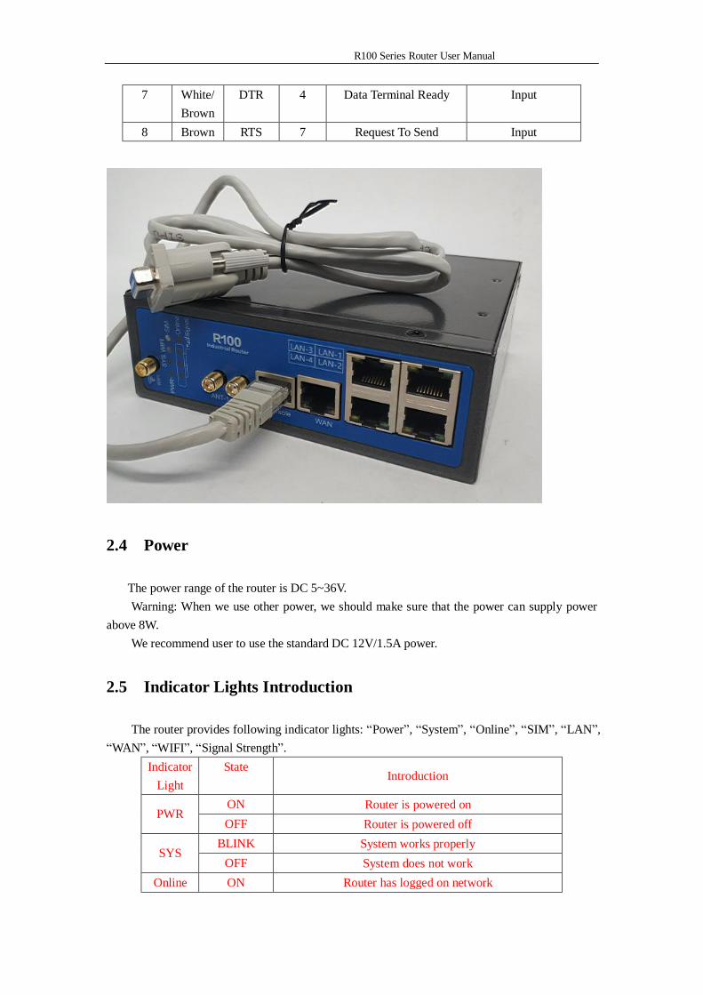
7 White/Brown
DTR 4 Data Terminal Ready Input
8 Brown RTS 7 Request To Send Input
2.4 Power
The power range of the router is DC 5~36V. Warning: When we use other power, we should make sure that the power can supply power
above 8W. We recommend user to use the standard DC 12V/1.5A power.
2.5 Indicator Lights Introduction
The router provides following indicator lights: “Power”, “System”, “Online”, “SIM”, “LAN”, “WAN”, “WIFI”, “Signal Strength”.
Indicator Light
State Introduction
ON Router is powered on PWR
OFF Router is powered off BLINK System works properly
SYS OFF System does not work
Online ON Router has logged on network
R100 Series Router User Manual
OFF Router hasn’t logged on network ON The SIM card has been identified SIM OFF The SIM card is not recognized OFF The corresponding interface of switch is not connected
LAN ON / BLINK
The corresponding interface of switch is connected /Communicating
OFF The interface of WAN is not connected WAN ON /
BLINK The interface of WAN is connected /Communicating
OFF WIFI is not active WIFI
ON WIFI is active One Light
ON Signal strength is weak
Two Lights ON
Signal strength is medium Signal
Strength Three
Lights ON Signal strength is good
2.6 Reset Button Introduction
The router has a “Reset” button to restore it to its original factory default settings. When user press the “Reset” button for up to 15s, the router will restore to its original factory default settings and restart automatically.
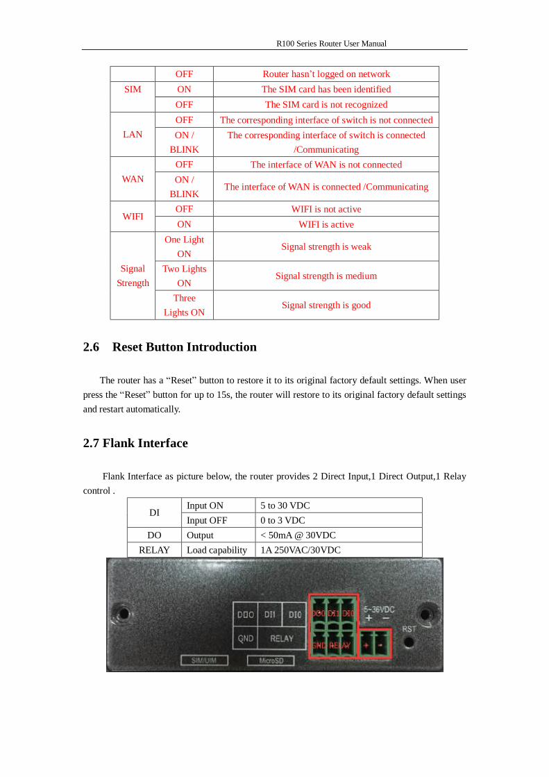
2.7 Flank Interface
Flank Interface as picture below, the router provides 2 Direct Input,1 Direct Output,1 Relay control .
Input ON 5 to 30 VDC DI
Input OFF 0 to 3 VDC DO Output < 50mA @ 30VDC
RELAY Load capability 1A 250VAC/30VDC
R100 Series Router User Manual
Chapter 3 Configuration and Management
This chapter describes how to configure and manage the router.
3.1 Configuration Connection
Before configuration, you should connect the router and your configuration PC with the supplied network cable. Plug the cable’s one end into the Local Network port of the router, and another end into your configure PC’s Ethernet port. The connection diagram is as following:
Please modify the IP address of PC as the same network segment address of the router, for instance, 192.168.1.9. Modify the mask code of PC as 255.255.255.0 and set the default gateway of PC as the router’s IP address (192.168.1.1).
3.2 Access the Configuration Web Page
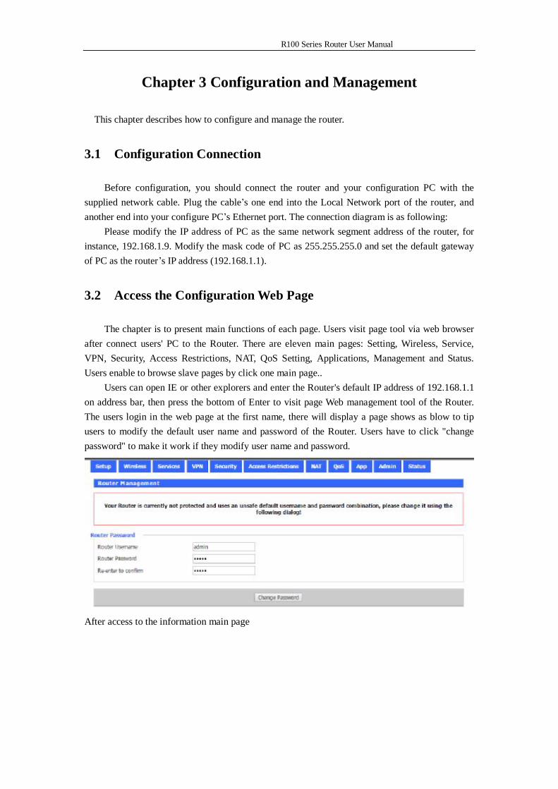
The chapter is to present main functions of each page. Users visit page tool via web browser after connect users' PC to the Router. There are eleven main pages: Setting, Wireless, Service, VPN, Security, Access Restrictions, NAT, QoS Setting, Applications, Management and Status. Users enable to browse slave pages by click one main page..
Users can open IE or other explorers and enter the Router's default IP address of 192.168.1.1 on address bar, then press the bottom of Enter to visit page Web management tool of the Router. The users login in the web page at the first name, there will display a page shows as blow to tip users to modify the default user name and password of the Router. Users have to click "change password" to make it work if they modify user name and password.
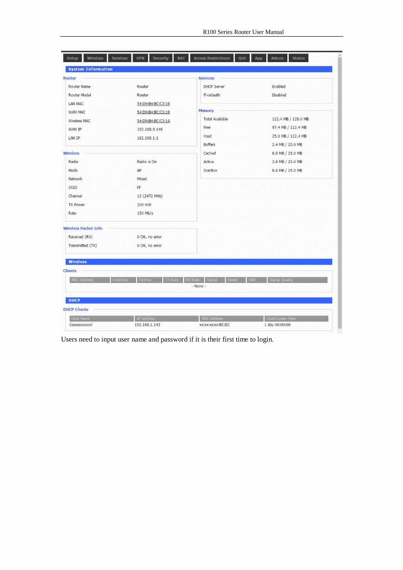
After access to the information main page
R100 Series Router User Manual
Users need to input user name and password if it is their first time to login.
R100 Series Router User Manual
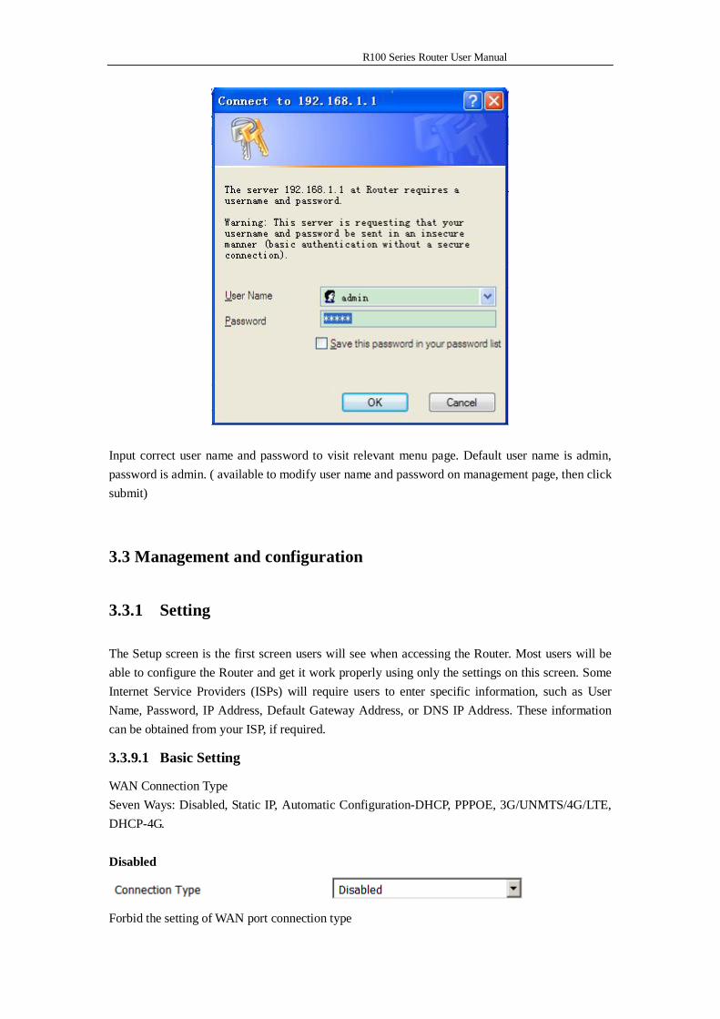
Input correct user name and password to visit relevant menu page. Default user name is admin, password is admin. ( available to modify user name and password on management page, then click submit)
3.3 Management and configuration
3.3.1 Setting
The Setup screen is the first screen users will see when accessing the Router. Most users will be able to configure the Router and get it work properly using only the settings on this screen. Some Internet Service Providers (ISPs) will require users to enter specific information, such as User Name, Password, IP Address, Default Gateway Address, or DNS IP Address. These information can be obtained from your ISP, if required.
3.3.9.1 Basic Setting
WAN Connection Type Seven Ways: Disabled, Static IP, Automatic Configuration-DHCP, PPPOE, 3G/UNMTS/4G/LTE, DHCP-4G. Disabled
Forbid the setting of WAN port connection type
R100 Series Router User Manual
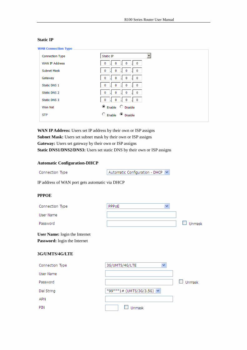
Static IP
WAN IP Address: Users set IP address by their own or ISP assigns Subnet Mask: Users set subnet mask by their own or ISP assigns Gateway: Users set gateway by their own or ISP assigns Static DNS1/DNS2/DNS3: Users set static DNS by their own or ISP assigns Automatic Configuration-DHCP
IP address of WAN port gets automatic via DHCP PPPOE
User Name: login the Internet Password: login the Internet 3G/UMTS/4G/LTE
R100 Series Router User Manual
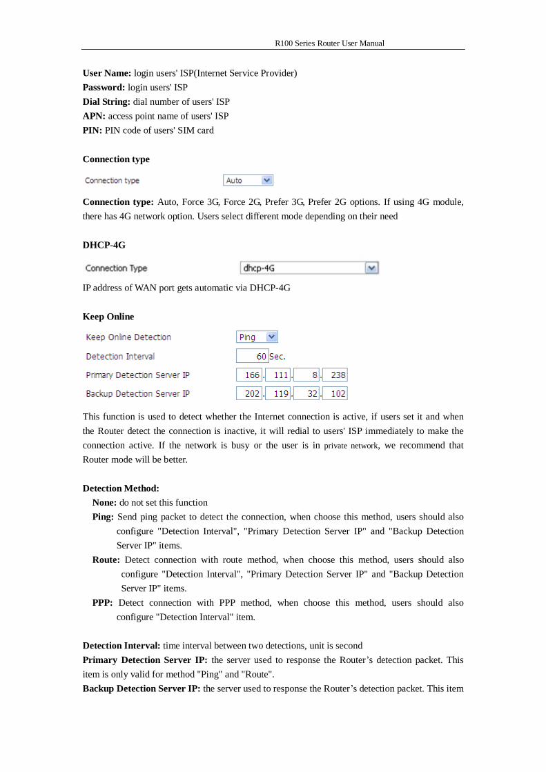
User Name: login users' ISP(Internet Service Provider) Password: login users' ISP Dial String: dial number of users' ISP APN: access point name of users' ISP PIN: PIN code of users' SIM card Connection type
Connection type: Auto, Force 3G, Force 2G, Prefer 3G, Prefer 2G options. If using 4G module, there has 4G network option. Users select different mode depending on their need DHCP-4G
IP address of WAN port gets automatic via DHCP-4G Keep Online
This function is used to detect whether the Internet connection is active, if users set it and when the Router detect the connection is inactive, it will redial to users' ISP immediately to make the connection active. If the network is busy or the user is in private network, we recommend that Router mode will be better. Detection Method:
None: do not set this function Ping: Send ping packet to detect the connection, when choose this method, users should also
configure "Detection Interval", "Primary Detection Server IP" and "Backup Detection Server IP" items.
Route: Detect connection with route method, when choose this method, users should also configure "Detection Interval", "Primary Detection Server IP" and "Backup Detection Server IP" items.
PPP: Detect connection with PPP method, when choose this method, users should also configure "Detection Interval" item.
Detection Interval: time interval between two detections, unit is second Primary Detection Server IP: the server used to response the Router’s detection packet. This item is only valid for method "Ping" and "Route". Backup Detection Server IP: the server used to response the Router’s detection packet. This item
R100 Series Router User Manual
is valid for method "Ping" and "Route". Note: When users choose the “Route” or “Ping” method, it’s quite important to make sure
that the “Primary Detection Server IP” and “Backup Detection Server IP” are usable and stable, because they have to response the detection packet frequently.
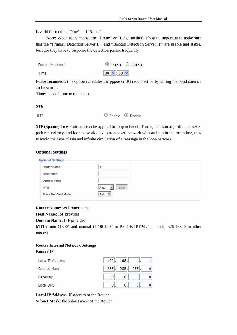
Force reconnect: this option schedules the pppoe or 3G reconnection by killing the pppd daemon and restart it. Time: needed time to reconnect STP
STP (Spaning Tree Protocol) can be applied to loop network. Through certain algorithm achieves path redundancy, and loop network cuts to tree-based network without loop in the meantime, thus to avoid the hyperplasia and infinite circulation of a message in the loop network Optional Settings
Router Name: set Router name Host Name: ISP provides Domain Name: ISP provides MTU: auto (1500) and manual (1200-1492 in PPPOE/PPTP/L2TP mode, 576-16320 in other modes) Router Internal Network Settings Router IP
Local IP Address: IP address of the Router Subnet Mask: the subnet mask of the Router
R100 Series Router User Manual
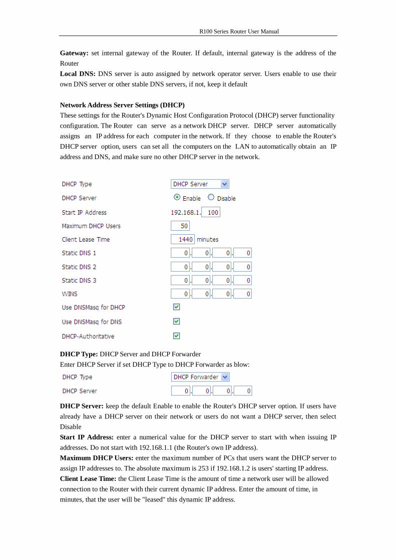
Gateway: set internal gateway of the Router. If default, internal gateway is the address of the Router Local DNS: DNS server is auto assigned by network operator server. Users enable to use their own DNS server or other stable DNS servers, if not, keep it default Network Address Server Settings (DHCP) These settings for the Router's Dynamic Host Configuration Protocol (DHCP) server functionality configuration. The Router can serve as a network DHCP server. DHCP server automatically assigns an IP address for each computer in the network. If they choose to enable the Router's DHCP server option, users can set all the computers on the LAN to automatically obtain an IP address and DNS, and make sure no other DHCP server in the network.
DHCP Type: DHCP Server and DHCP Forwarder Enter DHCP Server if set DHCP Type to DHCP Forwarder as blow:
DHCP Server: keep the default Enable to enable the Router's DHCP server option. If users have already have a DHCP server on their network or users do not want a DHCP server, then select Disable Start IP Address: enter a numerical value for the DHCP server to start with when issuing IP addresses. Do not start with 192.168.1.1 (the Router's own IP address). Maximum DHCP Users: enter the maximum number of PCs that users want the DHCP server to assign IP addresses to. The absolute maximum is 253 if 192.168.1.2 is users' starting IP address. Client Lease Time: the Client Lease Time is the amount of time a network user will be allowed connection to the Router with their current dynamic IP address. Enter the amount of time, in minutes, that the user will be "leased" this dynamic IP address.
R100 Series Router User Manual
Static DNS (1-3): the Domain Name System (DNS) is how the Internet translates domain or website names into Internet addresses or URLs. Users' ISP will provide them with at least one DNS Server IP address. If users wish to utilize another, enter that IP address in one of these fields. Users can enter up to three DNS Server IP addresses here. The Router will utilize them for quicker access to functioning DNS servers. WINS: the Windows Internet Naming Service (WINS) manages each PC's interaction with the Internet. If users use a WINS server, enter that server's IP address here. Otherwise, leave it blank. DNSMasq: users' domain name in the field of local search, increase the expansion of the host option, to adopt DNSMasq can assign IP addresses and DNS for the subnet, if select DNSMasq, dhcpd service is used for the subnet IP address and DNS. Time Settings Select time zone of your location. To use local time, leave the checkmark in the box next to Use local time.
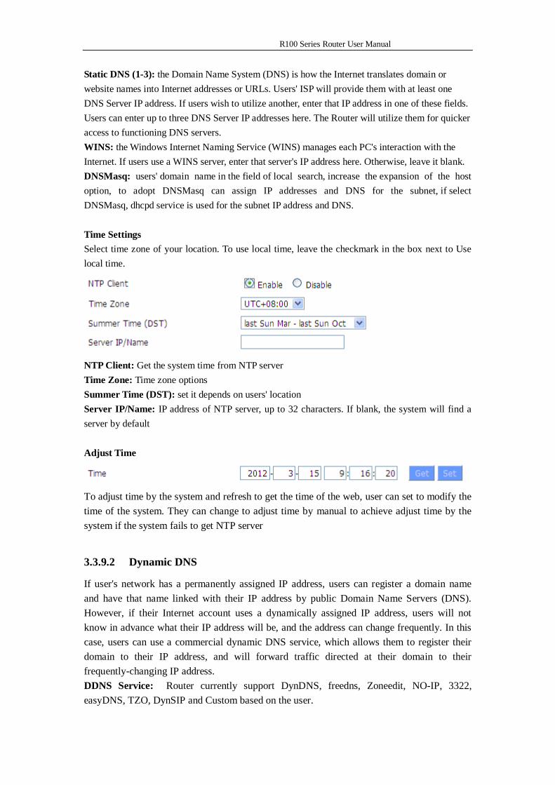
NTP Client: Get the system time from NTP server Time Zone: Time zone options Summer Time (DST): set it depends on users' location Server IP/Name: IP address of NTP server, up to 32 characters. If blank, the system will find a server by default Adjust Time
To adjust time by the system and refresh to get the time of the web, user can set to modify the time of the system. They can change to adjust time by manual to achieve adjust time by the system if the system fails to get NTP server
3.3.9.2 Dynamic DNS
If user's network has a permanently assigned IP address, users can register a domain name and have that name linked with their IP address by public Domain Name Servers (DNS). However, if their Internet account uses a dynamically assigned IP address, users will not know in advance what their IP address will be, and the address can change frequently. In this case, users can use a commercial dynamic DNS service, which allows them to register their domain to their IP address, and will forward traffic directed at their domain to their frequently-changing IP address. DDNS Service: Router currently support DynDNS, freedns, Zoneedit, NO-IP, 3322, easyDNS, TZO, DynSIP and Custom based on the user.
R100 Series Router User Manual
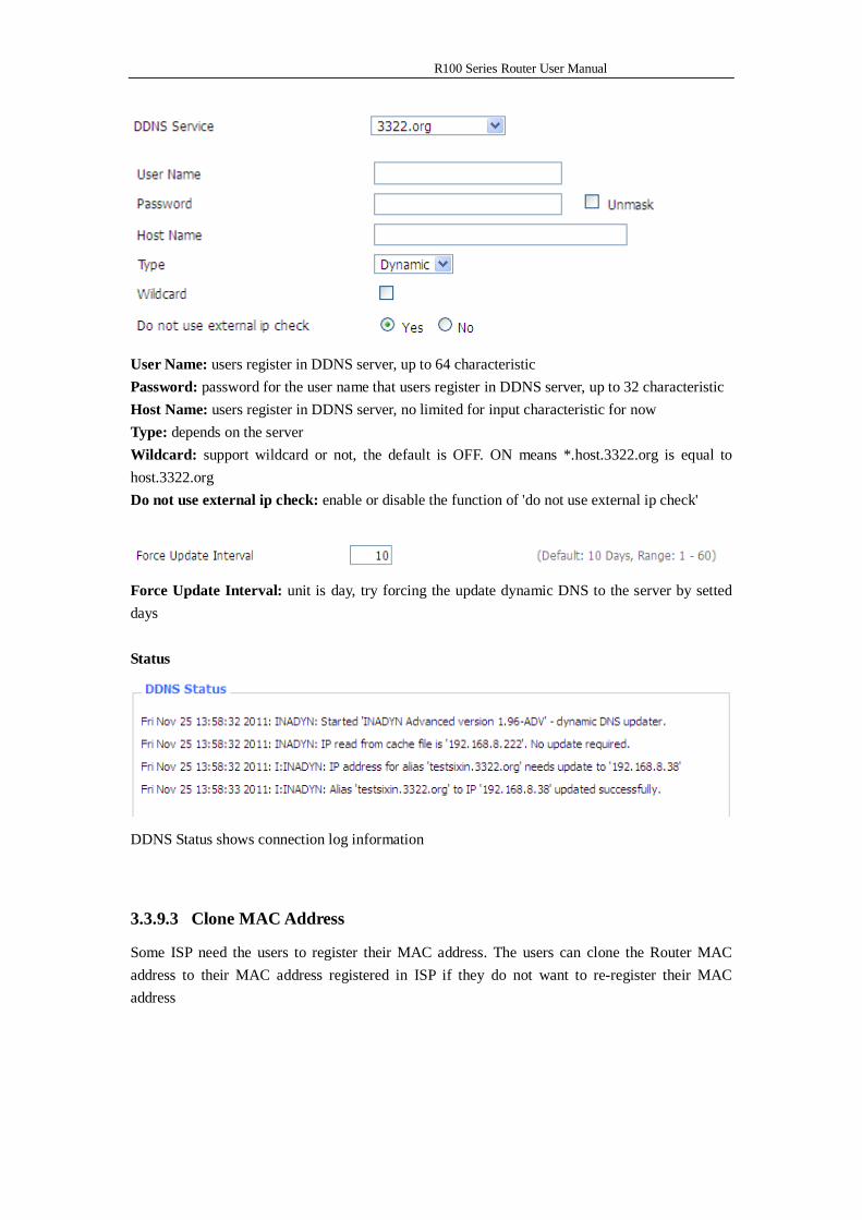
User Name: users register in DDNS server, up to 64 characteristic Password: password for the user name that users register in DDNS server, up to 32 characteristic Host Name: users register in DDNS server, no limited for input characteristic for now Type: depends on the server Wildcard: support wildcard or not, the default is OFF. ON means *.host.3322.org is equal to host.3322.org Do not use external ip check: enable or disable the function of 'do not use external ip check'
Force Update Interval: unit is day, try forcing the update dynamic DNS to the server by setted days Status
DDNS Status shows connection log information
3.3.9.3 Clone MAC Address
Some ISP need the users to register their MAC address. The users can clone the Router MAC address to their MAC address registered in ISP if they do not want to re-register their MAC address
R100 Series Router User Manual
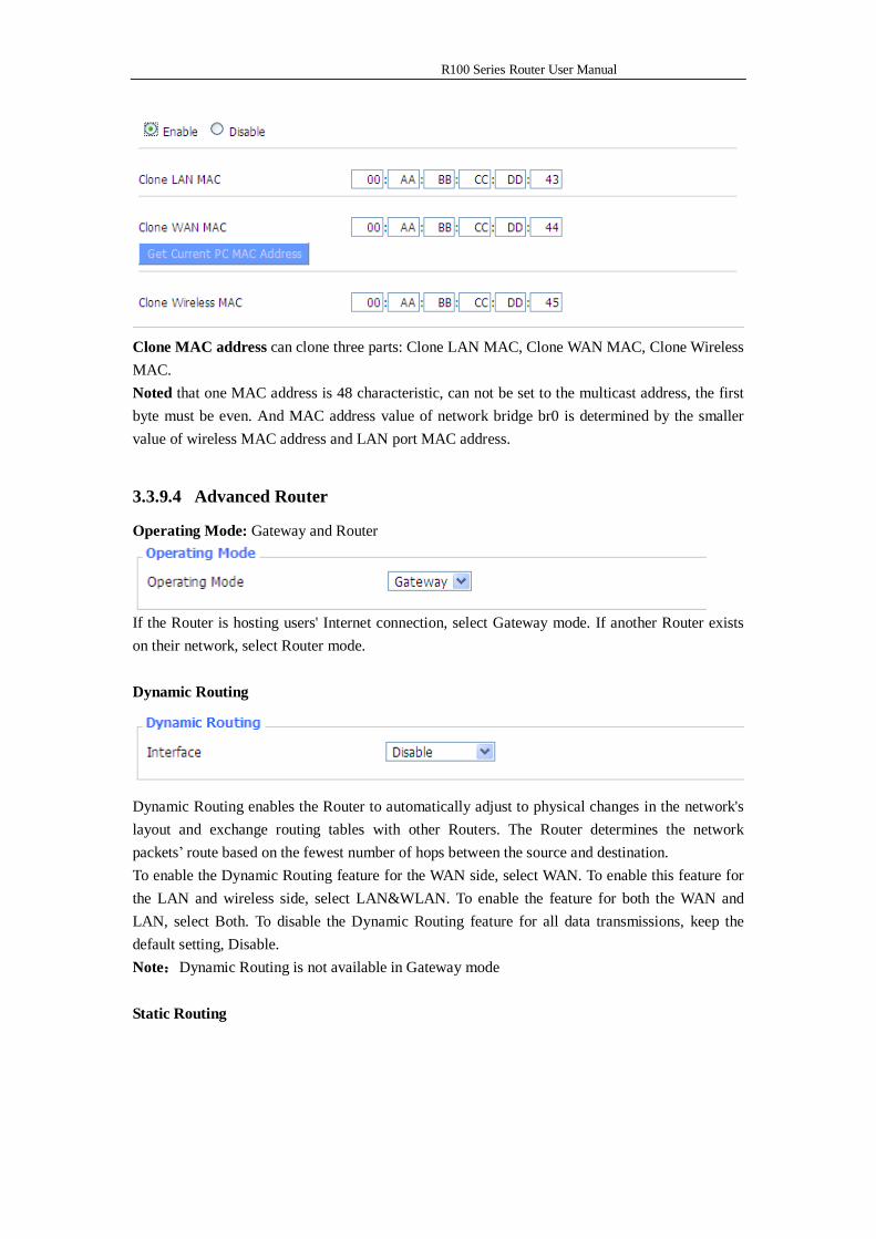
Clone MAC address can clone three parts: Clone LAN MAC, Clone WAN MAC, Clone Wireless MAC. Noted that one MAC address is 48 characteristic, can not be set to the multicast address, the first byte must be even. And MAC address value of network bridge br0 is determined by the smaller value of wireless MAC address and LAN port MAC address.
3.3.9.4 Advanced Router
Operating Mode: Gateway and Router
If the Router is hosting users' Internet connection, select Gateway mode. If another Router exists on their network, select Router mode. Dynamic Routing
Dynamic Routing enables the Router to automatically adjust to physical changes in the network's layout and exchange routing tables with other Routers. The Router determines the network packets’ route based on the fewest number of hops between the source and destination. To enable the Dynamic Routing feature for the WAN side, select WAN. To enable this feature for the LAN and wireless side, select LAN&WLAN. To enable the feature for both the WAN and LAN, select Both. To disable the Dynamic Routing feature for all data transmissions, keep the default setting, Disable. Note:Dynamic Routing is not available in Gateway mode Static Routing
R100 Series Router User Manual
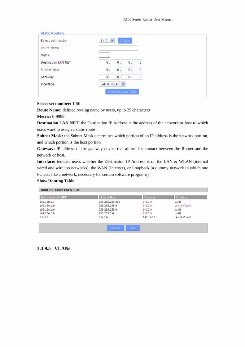
Select set number: 1-50 Route Name: defined routing name by users, up to 25 characters Metric: 0-9999 Destination LAN NET: the Destination IP Address is the address of the network or host to which users want to assign a static route Subnet Mask: the Subnet Mask determines which portion of an IP address is the network portion, and which portion is the host portion Gateway: IP address of the gateway device that allows for contact between the Router and the network or host. Interface: indicate users whether the Destination IP Address is on the LAN & WLAN (internal wired and wireless networks), the WAN (Internet), or Loopback (a dummy network in which one PC acts like a network, necessary for certain software programs) Show Routing Table
3.3.9.5 VLANs
R100 Series Router User Manual
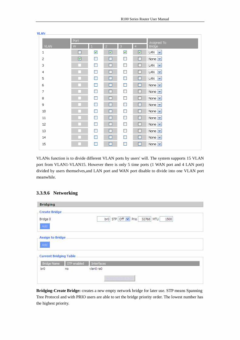
VLANs function is to divide different VLAN ports by users' will. The system supports 15 VLAN port from VLAN1-VLAN15. However there is only 5 time ports (1 WAN port and 4 LAN port) divided by users themselves,and LAN port and WAN port disable to divide into one VLAN port meanwhile.
3.3.9.6 Networking
Bridging-Create Bridge: creates a new empty network bridge for later use. STP means Spanning Tree Protocol and with PRIO users are able to set the bridge priority order. The lowest number has the highest priority.
R100 Series Router User Manual
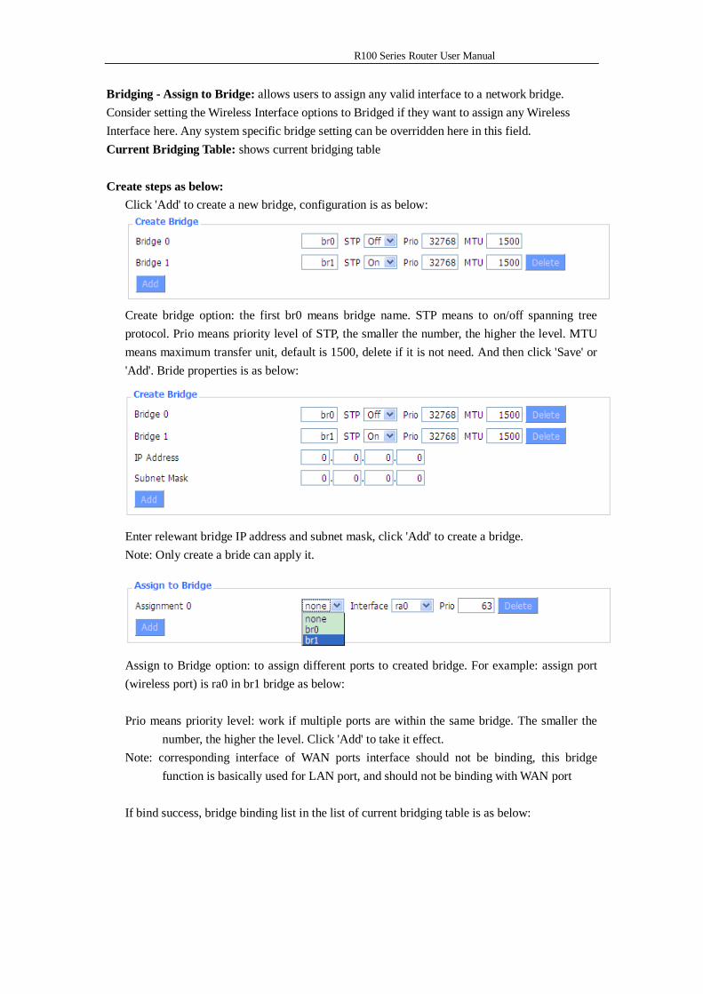
Bridging - Assign to Bridge: allows users to assign any valid interface to a network bridge. Consider setting the Wireless Interface options to Bridged if they want to assign any Wireless Interface here. Any system specific bridge setting can be overridden here in this field. Current Bridging Table: shows current bridging table Create steps as below:
Click 'Add' to create a new bridge, configuration is as below:
Create bridge option: the first br0 means bridge name. STP means to on/off spanning tree protocol. Prio means priority level of STP, the smaller the number, the higher the level. MTU means maximum transfer unit, default is 1500, delete if it is not need. And then click 'Save' or 'Add'. Bride properties is as below:
Enter relewant bridge IP address and subnet mask, click 'Add' to create a bridge. Note: Only create a bride can apply it.
Assign to Bridge option: to assign different ports to created bridge. For example: assign port (wireless port) is ra0 in br1 bridge as below: Prio means priority level: work if multiple ports are within the same bridge. The smaller the
number, the higher the level. Click 'Add' to take it effect. Note: corresponding interface of WAN ports interface should not be binding, this bridge
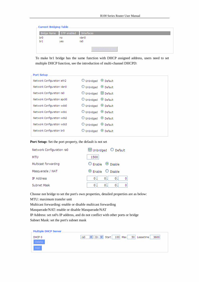
function is basically used for LAN port, and should not be binding with WAN port If bind success, bridge binding list in the list of current bridging table is as below:
R100 Series Router User Manual
To make br1 bridge has the same function with DHCP assigned address, users need to set multiple DHCP function, see the introduction of multi-channel DHCPD:
Port Setup: Set the port property, the default is not set
Choose not bridge to set the port's own properties, detailed properties are as below: MTU: maximum transfer unit Multicast forwarding: enable or disable multicast forwarding Masquerade/NAT: enable or disable Masquerade/NAT IP Address: set ra0's IP address, and do not conflict with other ports or bridge Subnet Mask: set the port's subnet mask
R100 Series Router User Manual
Multiple DHCPD: using multiple DHCP service. Click 'Add' in multiple DHCP server to appear relevant configuration. The first means the name of port or bridge (do not be configured as eth0), the second means whether to on DHCP. Start means start address, Max means maximum assigned DHCP clients, Leasetime means the client lease time, the unit is second, click 'Save' or 'Apply' to put it into effect after setting.
Note: Only configure and click 'Save' can configure the next, can not configure multiple DHCP at the same time.
3.3.2 Wireless
3.3.2.1 Basic Settings
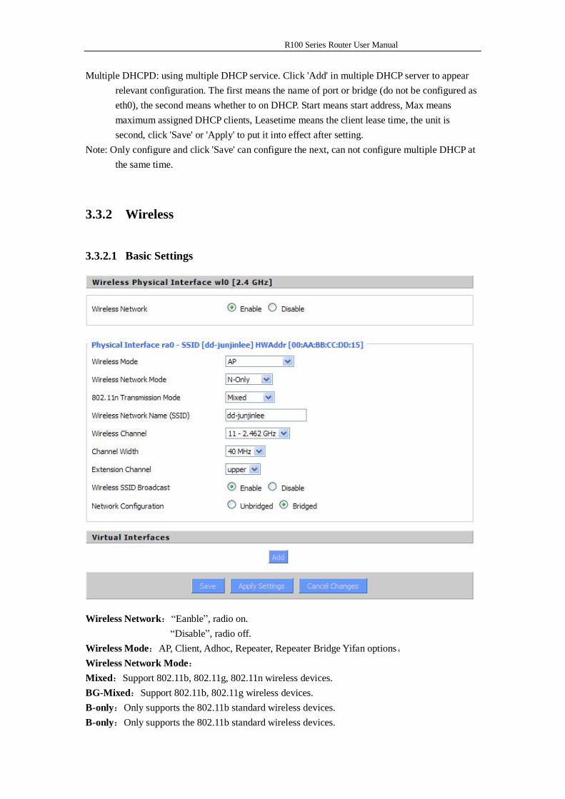
Wireless Network:“Eanble”, radio on. “Disable”, radio off. Wireless Mode:AP, Client, Adhoc, Repeater, Repeater Bridge Yifan options。 Wireless Network Mode: Mixed:Support 802.11b, 802.11g, 802.11n wireless devices. BG-Mixed:Support 802.11b, 802.11g wireless devices. B-only:Only supports the 802.11b standard wireless devices. B-only:Only supports the 802.11b standard wireless devices.
R100 Series Router User Manual
G-only:Only supports the 802.11g standard wireless devices. NG-Mixed:Support 802.11g, 802.11n wireless devices. N-only:Only supports the 802.11g standard wireless devices. 8021.11n Transmission Mode:In the wireless network mode to "N-only" choose to transfer its transmission mode. Greenfield: When you determine the surrounding environment, there is no other 802.11a/b/g devices use the same channel, use this mode to increase throughput. Other 802.11a/b/g devices use the same channel in the environment, the information you send may generate an error, re-issued.
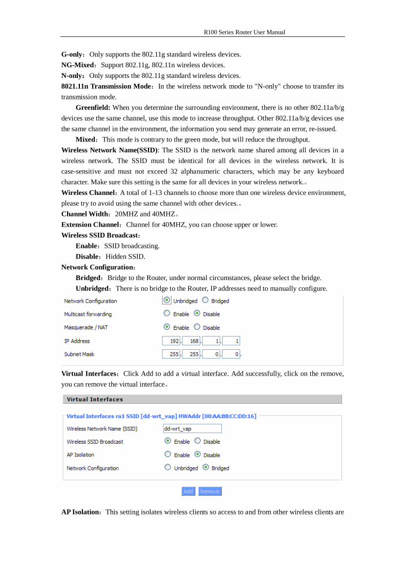
Mixed:This mode is contrary to the green mode, but will reduce the throughput. Wireless Network Name(SSID): The SSID is the network name shared among all devices in a wireless network. The SSID must be identical for all devices in the wireless network. It is case-sensitive and must not exceed 32 alphanumeric characters, which may be any keyboard character. Make sure this setting is the same for all devices in your wireless network.。 Wireless Channel:A total of 1-13 channels to choose more than one wireless device environment, please try to avoid using the same channel with other devices.。 Channel Width:20MHZ and 40MHZ。 Extension Channel:Channel for 40MHZ, you can choose upper or lower. Wireless SSID Broadcast: Enable:SSID broadcasting. Disable:Hidden SSID. Network Configuration: Bridged:Bridge to the Router, under normal circumstances, please select the bridge. Unbridged:There is no bridge to the Router, IP addresses need to manually configure.
Virtual Interfaces:Click Add to add a virtual interface. Add successfully, click on the remove, you can remove the virtual interface。
AP Isolation:This setting isolates wireless clients so access to and from other wireless clients are
R100 Series Router User Manual
stopped. Note:Save your changes, after changing the "Wireless Mode", "Wireless Network Mode", "wireless width", "broadband" option, please click on this button, and then configure the other options.
3.3.2.2 Wireless Security
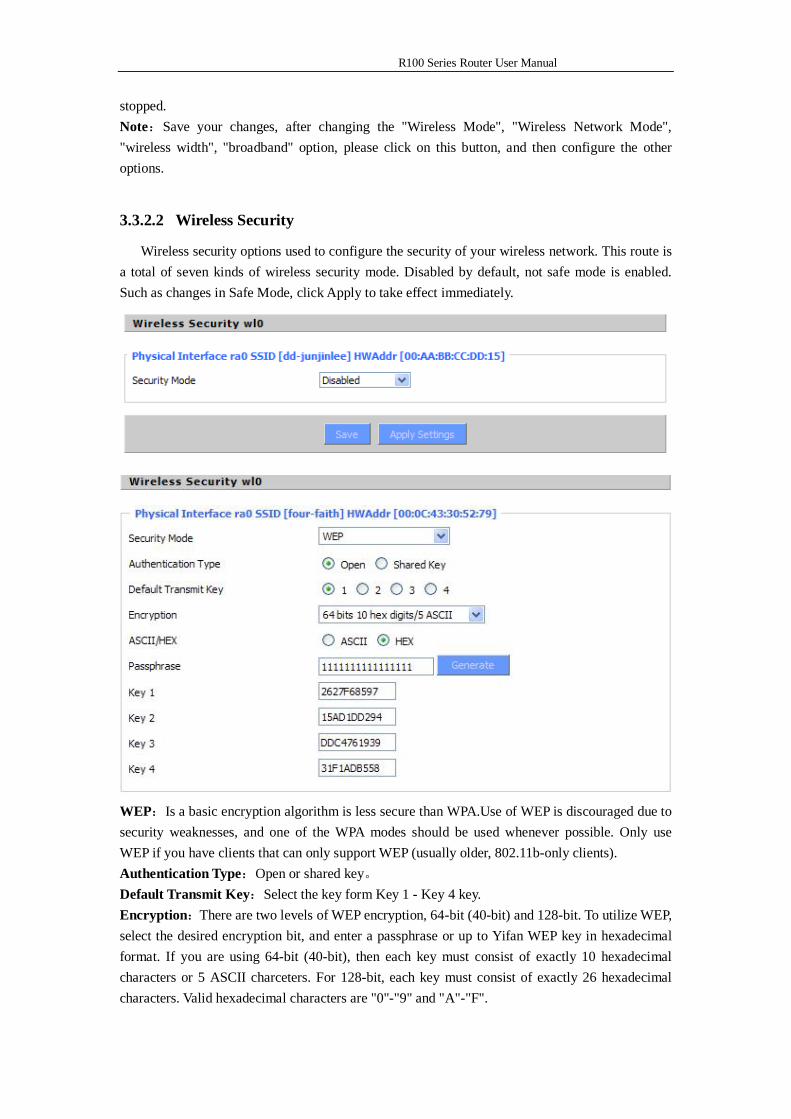
Wireless security options used to configure the security of your wireless network. This route is a total of seven kinds of wireless security mode. Disabled by default, not safe mode is enabled. Such as changes in Safe Mode, click Apply to take effect immediately.
WEP:Is a basic encryption algorithm is less secure than WPA.Use of WEP is discouraged due to security weaknesses, and one of the WPA modes should be used whenever possible. Only use WEP if you have clients that can only support WEP (usually older, 802.11b-only clients). Authentication Type:Open or shared key。 Default Transmit Key:Select the key form Key 1 - Key 4 key. Encryption:There are two levels of WEP encryption, 64-bit (40-bit) and 128-bit. To utilize WEP, select the desired encryption bit, and enter a passphrase or up to Yifan WEP key in hexadecimal format. If you are using 64-bit (40-bit), then each key must consist of exactly 10 hexadecimal characters or 5 ASCII charceters. For 128-bit, each key must consist of exactly 26 hexadecimal characters. Valid hexadecimal characters are "0"-"9" and "A"-"F".
R100 Series Router User Manual
ASCII/HEX: ASCII, the keys is 5 bit ASCII characters/13bit ASCII characters. HEX, the keys is 10bit/26 bit hex digits. Passphrase:The letters and numbers used to generate a key. Key1-Key4:Manually fill out or generated according to input the pass phrase.
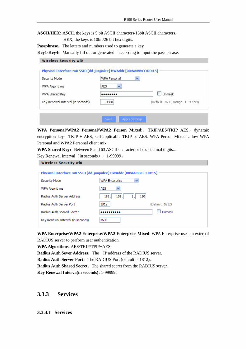
WPA Personal/WPA2 Personal/WPA2 Person Mixed:,TKIP/AES/TKIP+AES,dynamic encryption keys. TKIP + AES, self-applicable TKIP or AES. WPA Person Mixed, allow WPA Personal and WPA2 Personal client mix. WPA Shared Key:Between 8 and 63 ASCII character or hexadecimal digits.。 Key Renewal Interval(in seconds):1-99999。
WPA Enterprise/WPA2 Enterprise/WPA2 Enterprise Mixed: WPA Enterprise uses an external RADIUS server to perform user authentication. WPA Algorithms: AES/TKIP/TPIP+AES. Radius Auth Sever Address:The IP address of the RADIUS server. Radius Auth Server Port:The RADIUS Port (default is 1812)。 Radius Auth Shared Secret:The shared secret from the RADIUS server。 Key Renewal Interva(in seconds): 1-99999。
3.3.3 Services
3.3.4.1 Services
R100 Series Router User Manual
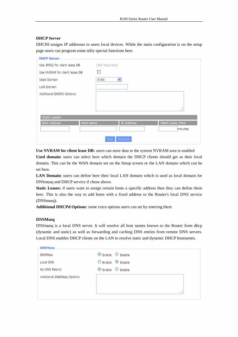
DHCP Server DHCPd assigns IP addresses to users local devices. While the main configuration is on the setup page users can program some nifty special functions here.
Use NVRAM for client lease DB: users can store data to the system NVRAM area is enabled Used domain: users can select here which domain the DHCP clients should get as their local domain. This can be the WAN domain set on the Setup screen or the LAN domain which can be set here. LAN Domain: users can define here their local LAN domain which is used as local domain for DNSmasq and DHCP service if chose above. Static Leases: if users want to assign certain hosts a specific address then they can define them here. This is also the way to add hosts with a fixed address to the Router's local DNS service (DNSmasq). Additional DHCPd Options: some extra options users can set by entering them DNSMasq DNSmasq is a local DNS server. It will resolve all host names known to the Router from dhcp (dynamic and static) as well as forwarding and caching DNS entries from remote DNS servers. Local DNS enables DHCP clients on the LAN to resolve static and dynamic DHCP hostnames.
R100 Series Router User Manual
Local DNS: enables DHCP clients on the LAN to resolve static and dynamic DHCP hostnames No DNS Rebind: when enabled, it can prevent an external attacker to access the Router's internal Web interface. It is a security measure Additional DNSMasq Options: some extra options users can set by entering them in Additional DNS Options. For example:
static allocation: dhcp-host=AB:CD:EF:11:22:33,192.168.0.10,myhost,myhost.domain,12h max lease number: dhcp-lease-max=2 DHCP server IP range: dhcp-range=192.168.0.110,192.168.0.111,12h
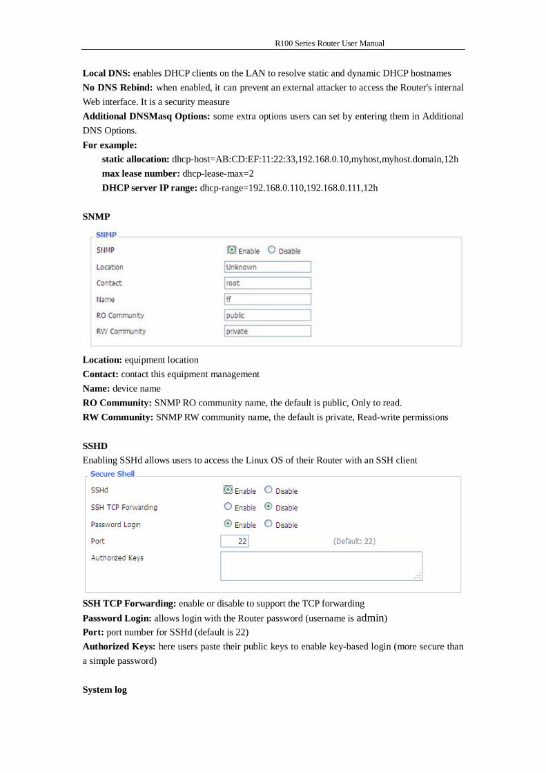
SNMP
Location: equipment location Contact: contact this equipment management Name: device name RO Community: SNMP RO community name, the default is public, Only to read. RW Community: SNMP RW community name, the default is private, Read-write permissions SSHD Enabling SSHd allows users to access the Linux OS of their Router with an SSH client
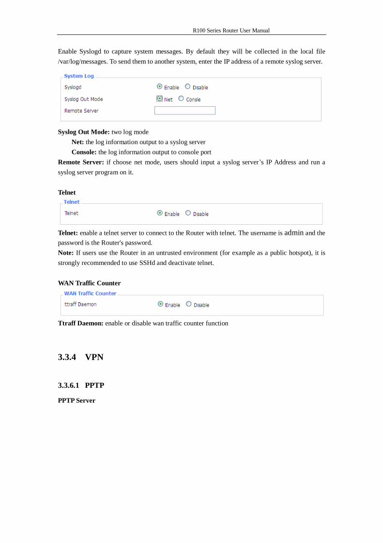
SSH TCP Forwarding: enable or disable to support the TCP forwarding Password Login: allows login with the Router password (username is admin) Port: port number for SSHd (default is 22) Authorized Keys: here users paste their public keys to enable key-based login (more secure than a simple password) System log
R100 Series Router User Manual
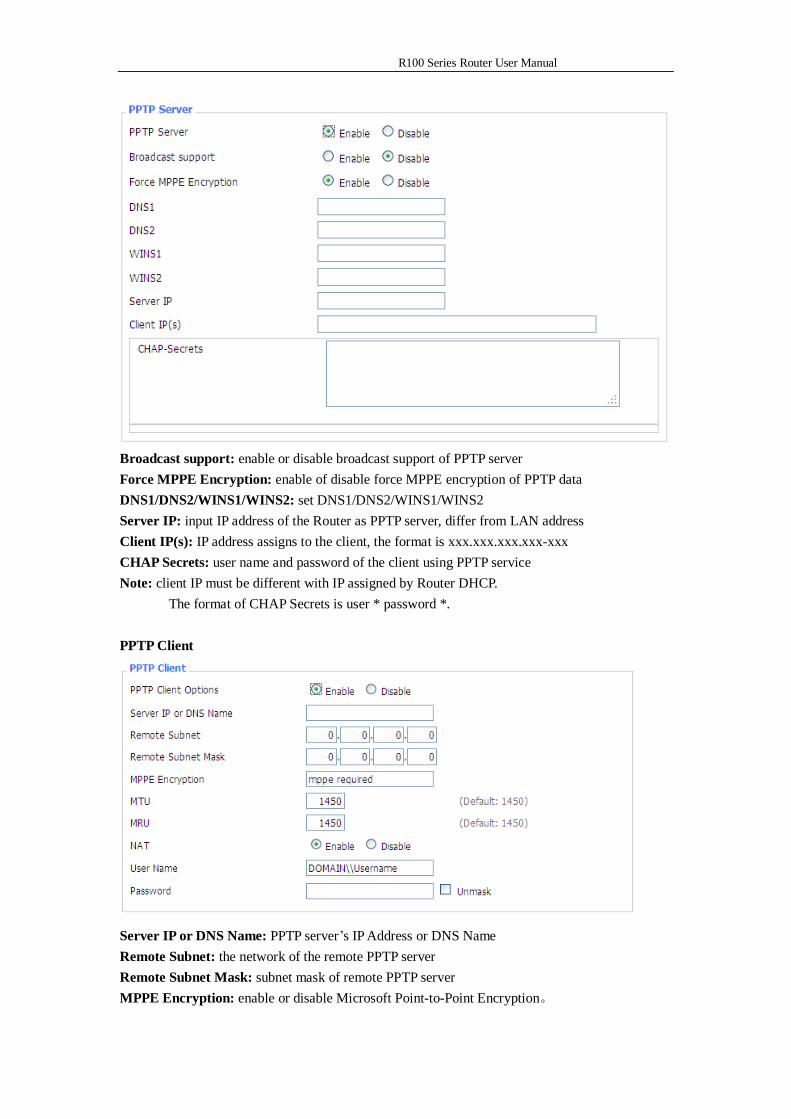
Enable Syslogd to capture system messages. By default they will be collected in the local file /var/log/messages. To send them to another system, enter the IP address of a remote syslog server.
Syslog Out Mode: two log mode
Net: the log information output to a syslog server Console: the log information output to console port
Remote Server: if choose net mode, users should input a syslog server’s IP Address and run a syslog server program on it. Telnet
Telnet: enable a telnet server to connect to the Router with telnet. The username is admin and the password is the Router's password. Note: If users use the Router in an untrusted environment (for example as a public hotspot), it is strongly recommended to use SSHd and deactivate telnet. WAN Traffic Counter
Ttraff Daemon: enable or disable wan traffic counter function
3.3.4 VPN
3.3.6.1 PPTP
PPTP Server
R100 Series Router User Manual
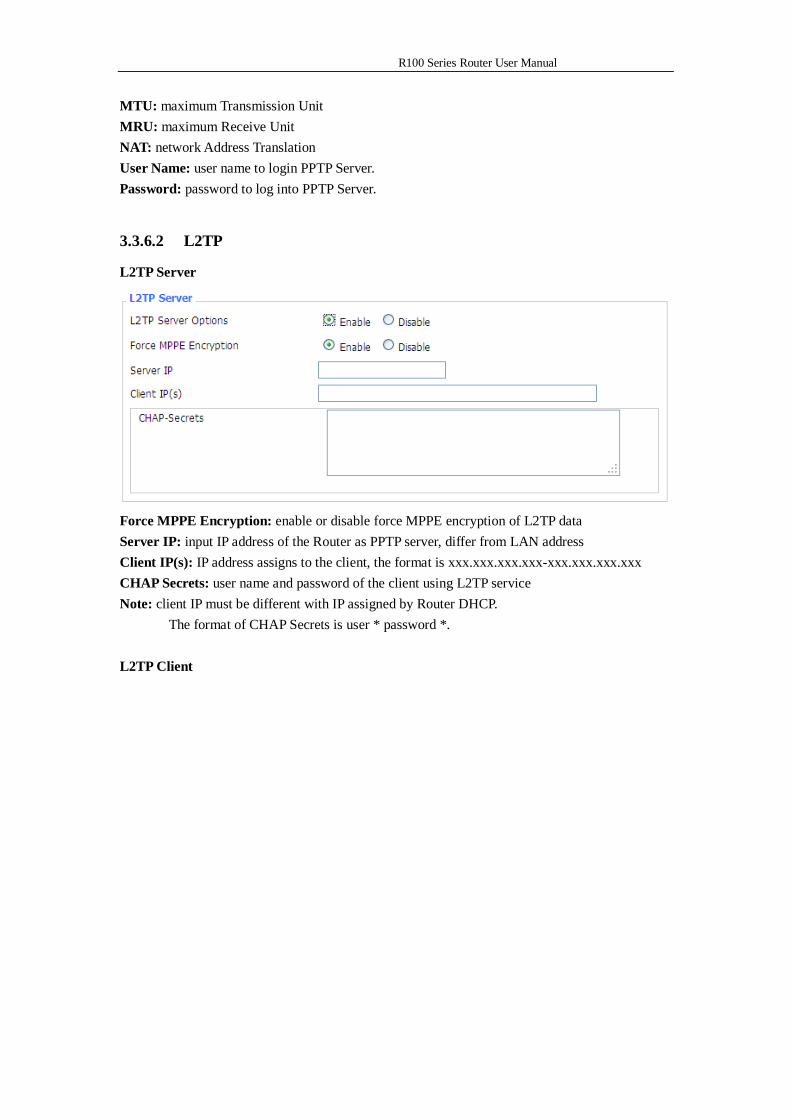
Broadcast support: enable or disable broadcast support of PPTP server Force MPPE Encryption: enable of disable force MPPE encryption of PPTP data DNS1/DNS2/WINS1/WINS2: set DNS1/DNS2/WINS1/WINS2 Server IP: input IP address of the Router as PPTP server, differ from LAN address Client IP(s): IP address assigns to the client, the format is xxx.xxx.xxx.xxx-xxx CHAP Secrets: user name and password of the client using PPTP service Note: client IP must be different with IP assigned by Router DHCP. The format of CHAP Secrets is user * password *. PPTP Client
Server IP or DNS Name: PPTP server’s IP Address or DNS Name Remote Subnet: the network of the remote PPTP server Remote Subnet Mask: subnet mask of remote PPTP server MPPE Encryption: enable or disable Microsoft Point-to-Point Encryption。
R100 Series Router User Manual
MTU: maximum Transmission Unit MRU: maximum Receive Unit NAT: network Address Translation User Name: user name to login PPTP Server. Password: password to log into PPTP Server.
3.3.6.2 L2TP
L2TP Server
Force MPPE Encryption: enable or disable force MPPE encryption of L2TP data Server IP: input IP address of the Router as PPTP server, differ from LAN address Client IP(s): IP address assigns to the client, the format is xxx.xxx.xxx.xxx-xxx.xxx.xxx.xxx CHAP Secrets: user name and password of the client using L2TP service Note: client IP must be different with IP assigned by Router DHCP. The format of CHAP Secrets is user * password *. L2TP Client
R100 Series Router User Manual
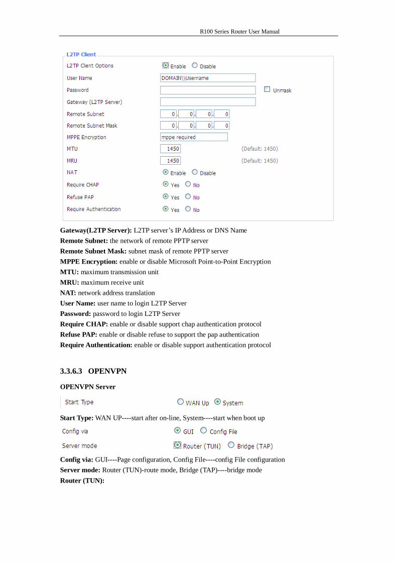
Gateway(L2TP Server): L2TP server’s IP Address or DNS Name Remote Subnet: the network of remote PPTP server Remote Subnet Mask: subnet mask of remote PPTP server MPPE Encryption: enable or disable Microsoft Point-to-Point Encryption MTU: maximum transmission unit MRU: maximum receive unit NAT: network address translation User Name: user name to login L2TP Server Password: password to login L2TP Server Require CHAP: enable or disable support chap authentication protocol Refuse PAP: enable or disable refuse to support the pap authentication Require Authentication: enable or disable support authentication protocol
3.3.6.3 OPENVPN
OPENVPN Server
Start Type: WAN UP----start after on-line, System----start when boot up
Config via: GUI----Page configuration, Config File----config File configuration Server mode: Router (TUN)-route mode, Bridge (TAP)----bridge mode Router (TUN):
R100 Series Router User Manual
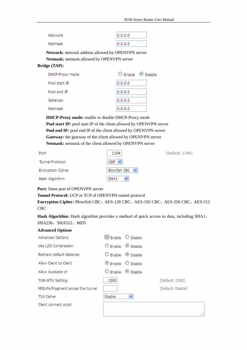
Network: network address allowed by OPENVPN server Netmask: netmask allowed by OPENVPN server
Bridge (TAP):
DHCP-Proxy mode: enable or disable DHCP-Proxy mode Pool start IP: pool start IP of the client allowed by OPENVPN server Pool end IP: pool end IP of the client allowed by OPENVPN server Gateway: the gateway of the client allowed by OPENVPN server Netmask: netmask of the client allowed by OPENVPN server
Port: listen port of OPENVPN server Tunnel Protocol: UCP or TCP of OPENVPN tunnel protocol Encryption Cipher: Blowfish CBC,AES-128 CBC,AES-192 CBC,AES-256 CBC,AES-512 CBC
Hash Algorithm: Hash algorithm provides a method of quick access to data, including SHA1,SHA256,SHA512,MD5
Advanced Options
R100 Series Router User Manual
Use LZO Compression: enable or disable use LZO compression for data transfer Redirect default Gateway: enable or disable redirect default gateway Allow Client to Client: enable or disable allow client to client Allow duplicate cn: enable or disable allow duplicate cn TUN MTU Setting: set the value of TUN MTU TCP MSS: MSS of TCP data TLS Cipher: TLS (Transport Layer Security) encryption standard supports AES-128 SHA and AES-256 SHA Client connect script: define some client script by user self
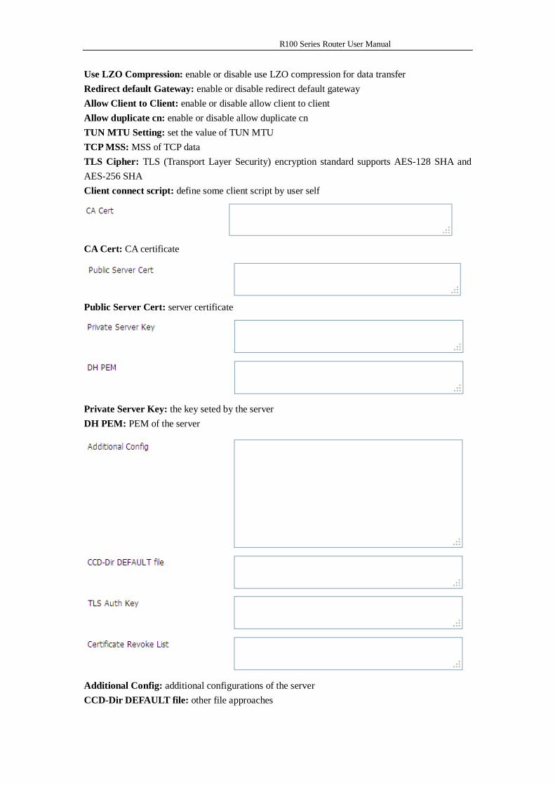
CA Cert: CA certificate
Public Server Cert: server certificate
Private Server Key: the key seted by the server DH PEM: PEM of the server
Additional Config: additional configurations of the server CCD-Dir DEFAULT file: other file approaches
R100 Series Router User Manual
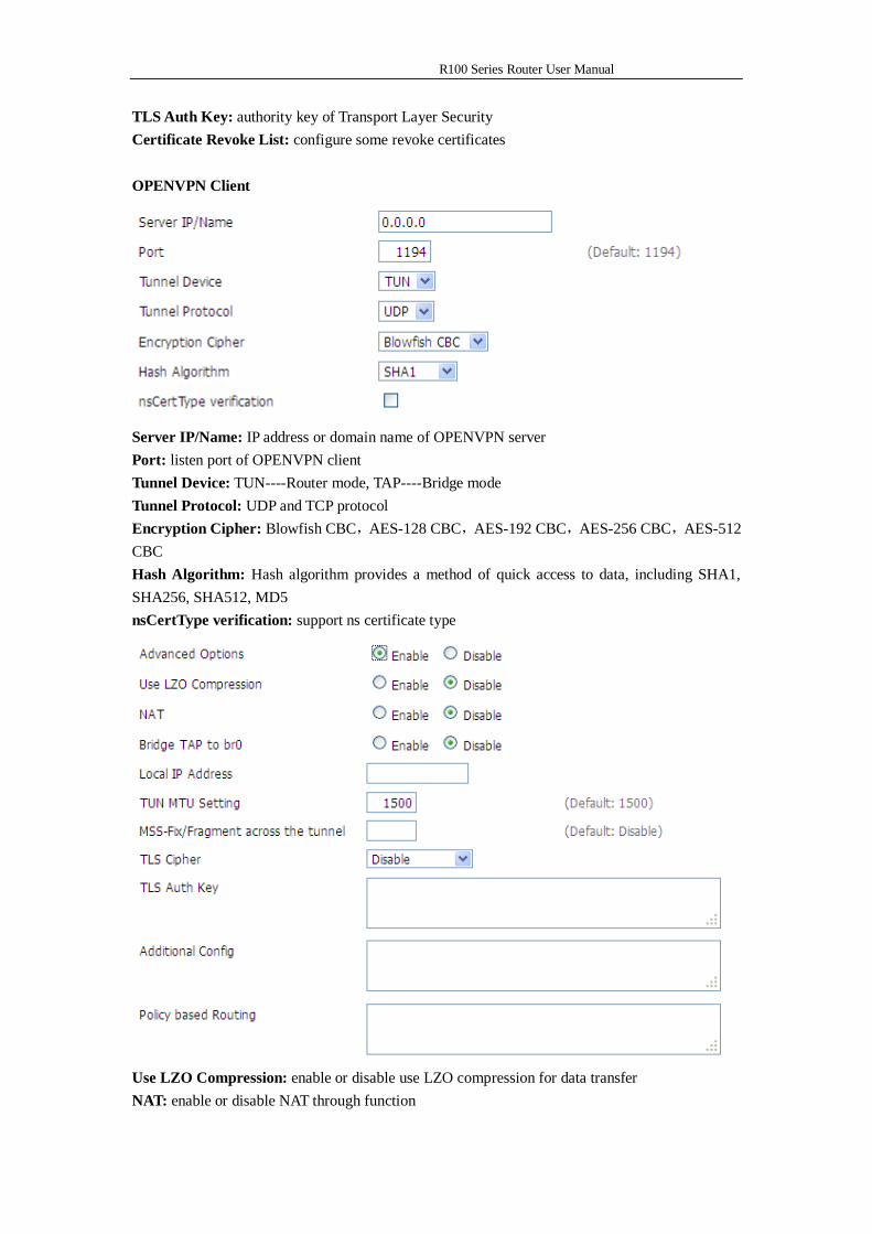
TLS Auth Key: authority key of Transport Layer Security Certificate Revoke List: configure some revoke certificates OPENVPN Client
Server IP/Name: IP address or domain name of OPENVPN server Port: listen port of OPENVPN client Tunnel Device: TUN----Router mode, TAP----Bridge mode Tunnel Protocol: UDP and TCP protocol Encryption Cipher: Blowfish CBC,AES-128 CBC,AES-192 CBC,AES-256 CBC,AES-512 CBC Hash Algorithm: Hash algorithm provides a method of quick access to data, including SHA1, SHA256, SHA512, MD5 nsCertType verification: support ns certificate type
Use LZO Compression: enable or disable use LZO compression for data transfer NAT: enable or disable NAT through function
R100 Series Router User Manual
Bridge TAP to br0: enable or disable bridge TAP to br0 Local IP Address: set IP address of local OPENVPN client TUN MTU Setting: set MTU value of the tunnel TCP MSS: mss of TCP data TLS Cipher: TLS (Transport Layer Security) encryption standard supports AES-128 SHA and AES-256 SHA TLS Auth Key: authority key of Transport Layer Security Additional Config: additional configurations of OPENVPN server Policy based Routing: input some defined routing policy
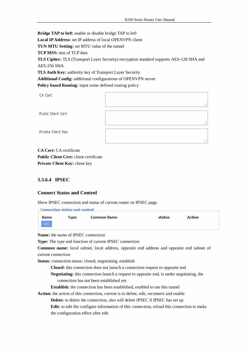
CA Cert: CA certificate Public Client Cert: client certificate Private Client Key: client key
3.3.6.4 IPSEC
Connect Status and Control
Show IPSEC connection and status of current router on IPSEC page.
Name: the name of IPSEC connection Type: The type and function of current IPSEC connection Common name: local subnet, local address, opposite end address and opposite end subnet of current connection Status: connection status: closed, negotiating, establish Closed: this connection does not launch a connection request to opposite end Negotiating: this connection launch a request to opposite end, is under negotiating, the connection has not been established yet Establish: the connection has been established, enabled to use this tunnel Action: the action of this connection, current is to delete, edit, reconnect and enable Delete: to delete the connection, also will delete IPSEC if IPSEC has set up Edit: to edit the configure information of this connection, reload this connection to make the configuration effect after edit
R100 Series Router User Manual
Reconnect: this action will remove current tunnel, and re-launch tunnel establish request Enable: when the connection is enable, it will launch tunnel establish request when the system reboot or reconnect, otherwise the connection will not do it Add: to add a new IPSEC connection
Add IPSEC connection or edit IPSEC connection
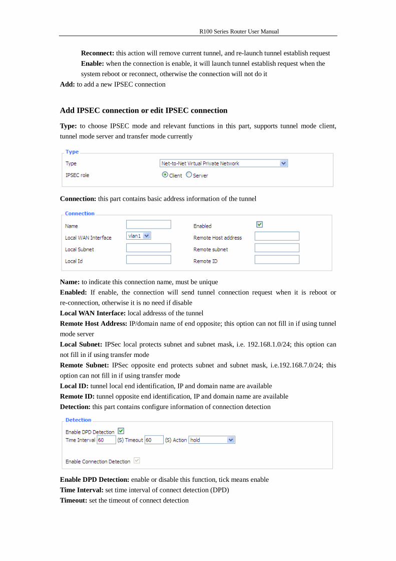
Type: to choose IPSEC mode and relevant functions in this part, supports tunnel mode client, tunnel mode server and transfer mode currently
Connection: this part contains basic address information of the tunnel
Name: to indicate this connection name, must be unique Enabled: If enable, the connection will send tunnel connection request when it is reboot or re-connection, otherwise it is no need if disable Local WAN Interface: local addresss of the tunnel Remote Host Address: IP/domain name of end opposite; this option can not fill in if using tunnel mode server Local Subnet: IPSec local protects subnet and subnet mask, i.e. 192.168.1.0/24; this option can not fill in if using transfer mode Remote Subnet: IPSec opposite end protects subnet and subnet mask, i.e.192.168.7.0/24; this option can not fill in if using transfer mode Local ID: tunnel local end identification, IP and domain name are available Remote ID: tunnel opposite end identification, IP and domain name are available Detection: this part contains configure information of connection detection
Enable DPD Detection: enable or disable this function, tick means enable Time Interval: set time interval of connect detection (DPD) Timeout: set the timeout of connect detection
R100 Series Router User Manual
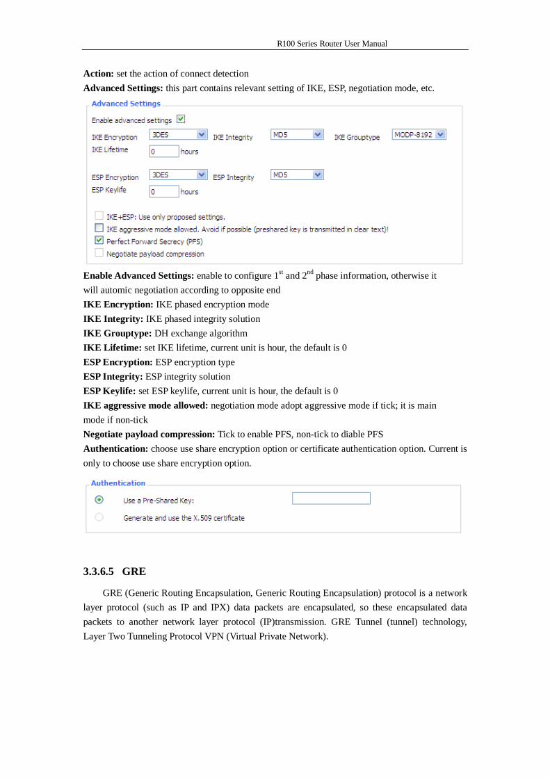
Action: set the action of connect detection Advanced Settings: this part contains relevant setting of IKE, ESP, negotiation mode, etc.
Enable Advanced Settings: enable to configure 1st and 2nd phase information, otherwise it will automic negotiation according to opposite end IKE Encryption: IKE phased encryption mode IKE Integrity: IKE phased integrity solution IKE Grouptype: DH exchange algorithm IKE Lifetime: set IKE lifetime, current unit is hour, the default is 0 ESP Encryption: ESP encryption type ESP Integrity: ESP integrity solution ESP Keylife: set ESP keylife, current unit is hour, the default is 0 IKE aggressive mode allowed: negotiation mode adopt aggressive mode if tick; it is main mode if non-tick Negotiate payload compression: Tick to enable PFS, non-tick to diable PFS Authentication: choose use share encryption option or certificate authentication option. Current is only to choose use share encryption option.
3.3.6.5 GRE
GRE (Generic Routing Encapsulation, Generic Routing Encapsulation) protocol is a network layer protocol (such as IP and IPX) data packets are encapsulated, so these encapsulated data packets to another network layer protocol (IP)transmission. GRE Tunnel (tunnel) technology, Layer Two Tunneling Protocol VPN (Virtual Private Network).
R100 Series Router User Manual
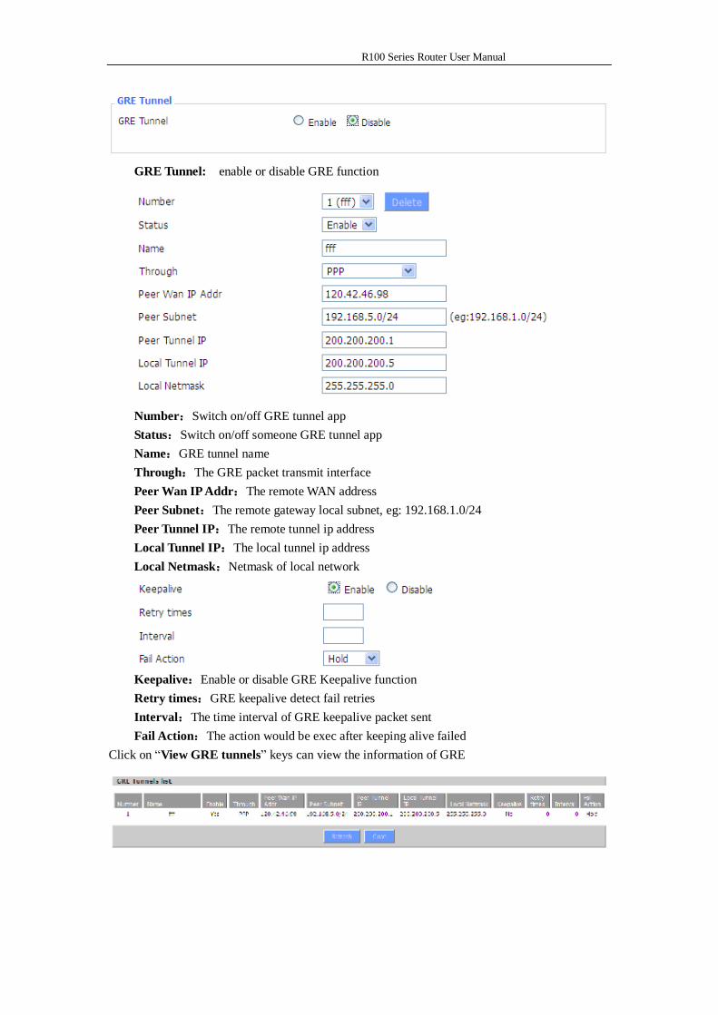
GRE Tunnel: enable or disable GRE function
Number:Switch on/off GRE tunnel app Status:Switch on/off someone GRE tunnel app Name:GRE tunnel name Through:The GRE packet transmit interface Peer Wan IP Addr:The remote WAN address Peer Subnet:The remote gateway local subnet, eg: 192.168.1.0/24 Peer Tunnel IP:The remote tunnel ip address Local Tunnel IP:The local tunnel ip address Local Netmask:Netmask of local network
Keepalive:Enable or disable GRE Keepalive function Retry times:GRE keepalive detect fail retries Interval:The time interval of GRE keepalive packet sent Fail Action:The action would be exec after keeping alive failed
Click on “View GRE tunnels” keys can view the information of GRE
R100 Series Router User Manual
3.3.5 Security
3.3.5.1 Firewall
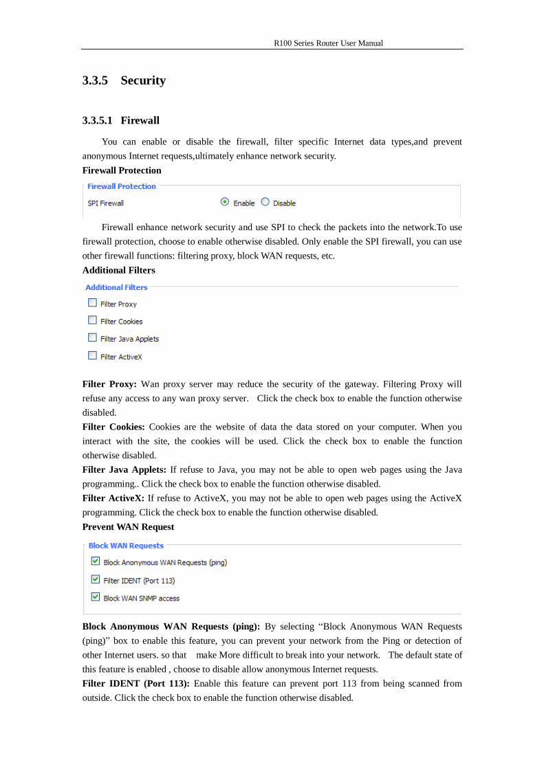
You can enable or disable the firewall, filter specific Internet data types,and prevent anonymous Internet requests,ultimately enhance network security. Firewall Protection
Firewall enhance network security and use SPI to check the packets into the network.To use
firewall protection, choose to enable otherwise disabled. Only enable the SPI firewall, you can use other firewall functions: filtering proxy, block WAN requests, etc. Additional Filters
Filter Proxy: Wan proxy server may reduce the security of the gateway. Filtering Proxy will refuse any access to any wan proxy server. Click the check box to enable the function otherwise disabled. Filter Cookies: Cookies are the website of data the data stored on your computer. When you interact with the site, the cookies will be used. Click the check box to enable the function otherwise disabled. Filter Java Applets: If refuse to Java, you may not be able to open web pages using the Java programming.. Click the check box to enable the function otherwise disabled. Filter ActiveX: If refuse to ActiveX, you may not be able to open web pages using the ActiveX programming. Click the check box to enable the function otherwise disabled. Prevent WAN Request
Block Anonymous WAN Requests (ping): By selecting “Block Anonymous WAN Requests (ping)” box to enable this feature, you can prevent your network from the Ping or detection of other Internet users. so that make More difficult to break into your network. The default state of this feature is enabled , choose to disable allow anonymous Internet requests. Filter IDENT (Port 113): Enable this feature can prevent port 113 from being scanned from outside. Click the check box to enable the function otherwise disabled.
R100 Series Router User Manual
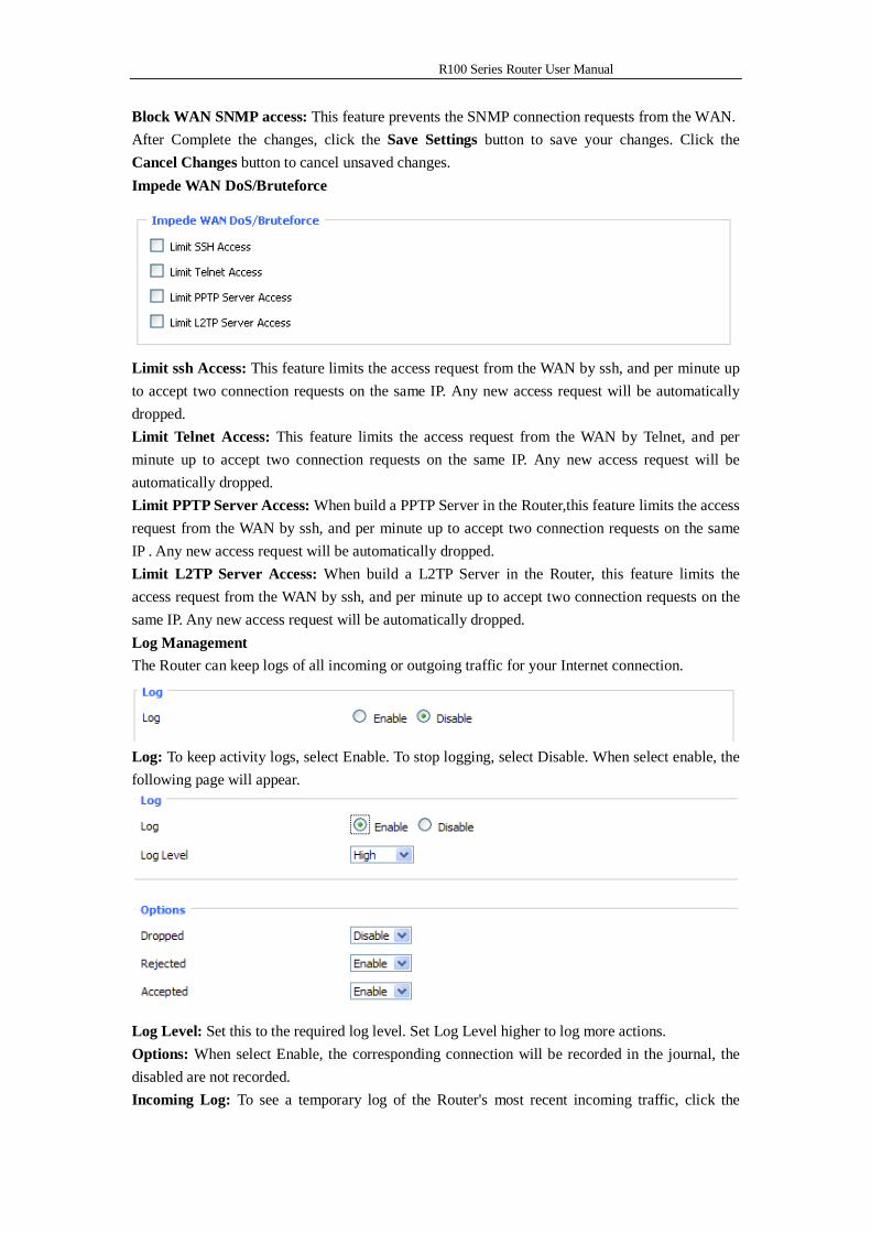
Block WAN SNMP access: This feature prevents the SNMP connection requests from the WAN. After Complete the changes, click the Save Settings button to save your changes. Click the Cancel Changes button to cancel unsaved changes. Impede WAN DoS/Bruteforce
Limit ssh Access: This feature limits the access request from the WAN by ssh, and per minute up to accept two connection requests on the same IP. Any new access request will be automatically dropped. Limit Telnet Access: This feature limits the access request from the WAN by Telnet, and per minute up to accept two connection requests on the same IP. Any new access request will be automatically dropped. Limit PPTP Server Access: When build a PPTP Server in the Router,this feature limits the access request from the WAN by ssh, and per minute up to accept two connection requests on the same IP . Any new access request will be automatically dropped. Limit L2TP Server Access: When build a L2TP Server in the Router, this feature limits the access request from the WAN by ssh, and per minute up to accept two connection requests on the same IP. Any new access request will be automatically dropped. Log Management The Router can keep logs of all incoming or outgoing traffic for your Internet connection.
Log: To keep activity logs, select Enable. To stop logging, select Disable. When select enable, the following page will appear.
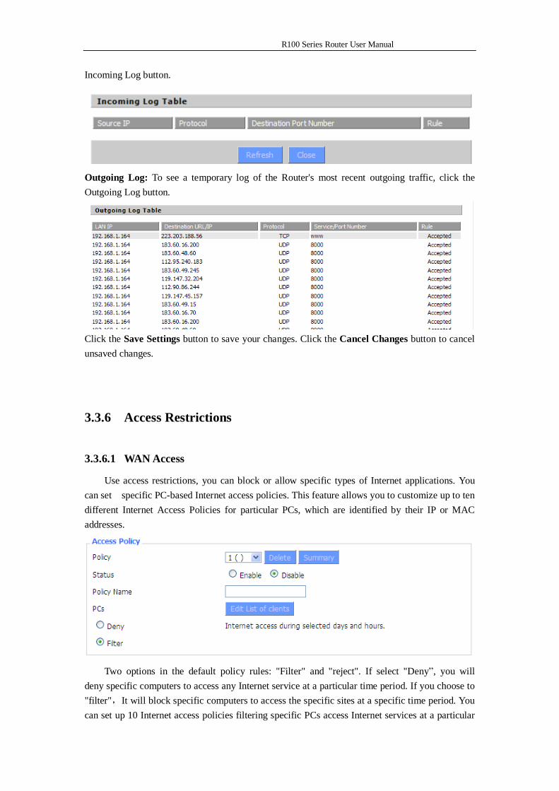
Log Level: Set this to the required log level. Set Log Level higher to log more actions. Options: When select Enable, the corresponding connection will be recorded in the journal, the disabled are not recorded. Incoming Log: To see a temporary log of the Router's most recent incoming traffic, click the
R100 Series Router User Manual
Incoming Log button.
Outgoing Log: To see a temporary log of the Router's most recent outgoing traffic, click the Outgoing Log button.
Click the Save Settings button to save your changes. Click the Cancel Changes button to cancel unsaved changes.
3.3.6 Access Restrictions
3.3.6.1 WAN Access
Use access restrictions, you can block or allow specific types of Internet applications. You can set specific PC-based Internet access policies. This feature allows you to customize up to ten different Internet Access Policies for particular PCs, which are identified by their IP or MAC addresses.
Two options in the default policy rules: "Filter" and "reject". If select "Deny”, you will
deny specific computers to access any Internet service at a particular time period. If you choose to "filter",It will block specific computers to access the specific sites at a specific time period. You can set up 10 Internet access policies filtering specific PCs access Internet services at a particular
R100 Series Router User Manual
time period. Access Policy: You may define up to 10 access policies. Click Delete to delete a policy or Summary to see a summary of the policy. Status: Enable or disable a policy. Policy Name: You may assign a name to your policy. PCs: The part is used to edit client list, the strategy is only effective for the PC in the list.
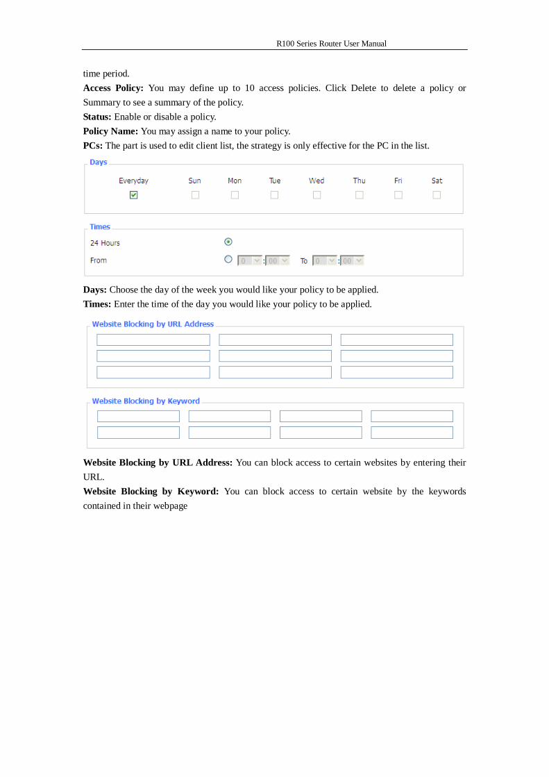
Days: Choose the day of the week you would like your policy to be applied. Times: Enter the time of the day you would like your policy to be applied.
Website Blocking by URL Address: You can block access to certain websites by entering their URL. Website Blocking by Keyword: You can block access to certain website by the keywords contained in their webpage
R100 Series Router User Manual
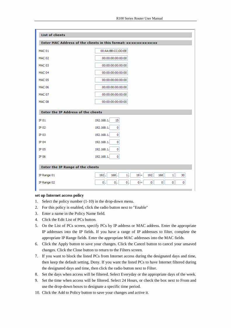
set up Internet access policy 1. Select the policy number (1-10) in the drop-down menu. 2. For this policy is enabled, click the radio button next to "Enable" 3. Enter a name in the Policy Name field. 4. Click the Edit List of PCs button. 5. On the List of PCs screen, specify PCs by IP address or MAC address. Enter the appropriate
IP addresses into the IP fields. If you have a range of IP addresses to filter, complete the appropriate IP Range fields. Enter the appropriate MAC addresses into the MAC fields.
6. Click the Apply button to save your changes. Click the Cancel button to cancel your unsaved changes. Click the Close button to return to the Filters screen.
7. If you want to block the listed PCs from Internet access during the designated days and time, then keep the default setting, Deny. If you want the listed PCs to have Internet filtered during the designated days and time, then click the radio button next to Filter.
8. Set the days when access will be filtered. Select Everyday or the appropriate days of the week. 9. Set the time when access will be filtered. Select 24 Hours, or check the box next to From and
use the drop-down boxes to designate a specific time period. 10. Click the Add to Policy button to save your changes and active it.
R100 Series Router User Manual
11. To create or edit additional policies, repeat steps 1-9. 12. To delete an Internet Access Policy, select the policy number, and click the Delete button. Note:
3.3.3.1 The default factory value of policy rules is "filtered". If the user chooses the default policy rules for "refuse", and editing strategies to save or directly to save the settings. If the strategy edited is the first, it will be automatically saved into the second, if not the first, keep the original number.
3.3.3.2 Turn off the power of the Router or reboot the Router can cause a temporary failure。After the failure of the Router, if can not automatically synchronized NTP time server, you need to recalibrate to ensure the correct implementation of the relevant period control function.
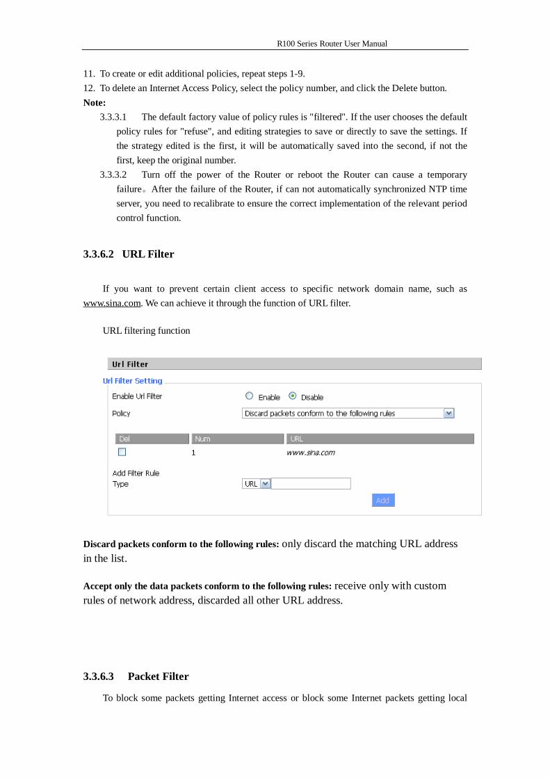
3.3.6.2 URL Filter
If you want to prevent certain client access to specific network domain name, such as www.sina.com. We can achieve it through the function of URL filter.
URL filtering function
Discard packets conform to the following rules: only discard the matching URL address in the list.
Accept only the data packets conform to the following rules: receive only with custom rules of network address, discarded all other URL address.
3.3.6.3 Packet Filter
To block some packets getting Internet access or block some Internet packets getting local
R100 Series Router User Manual
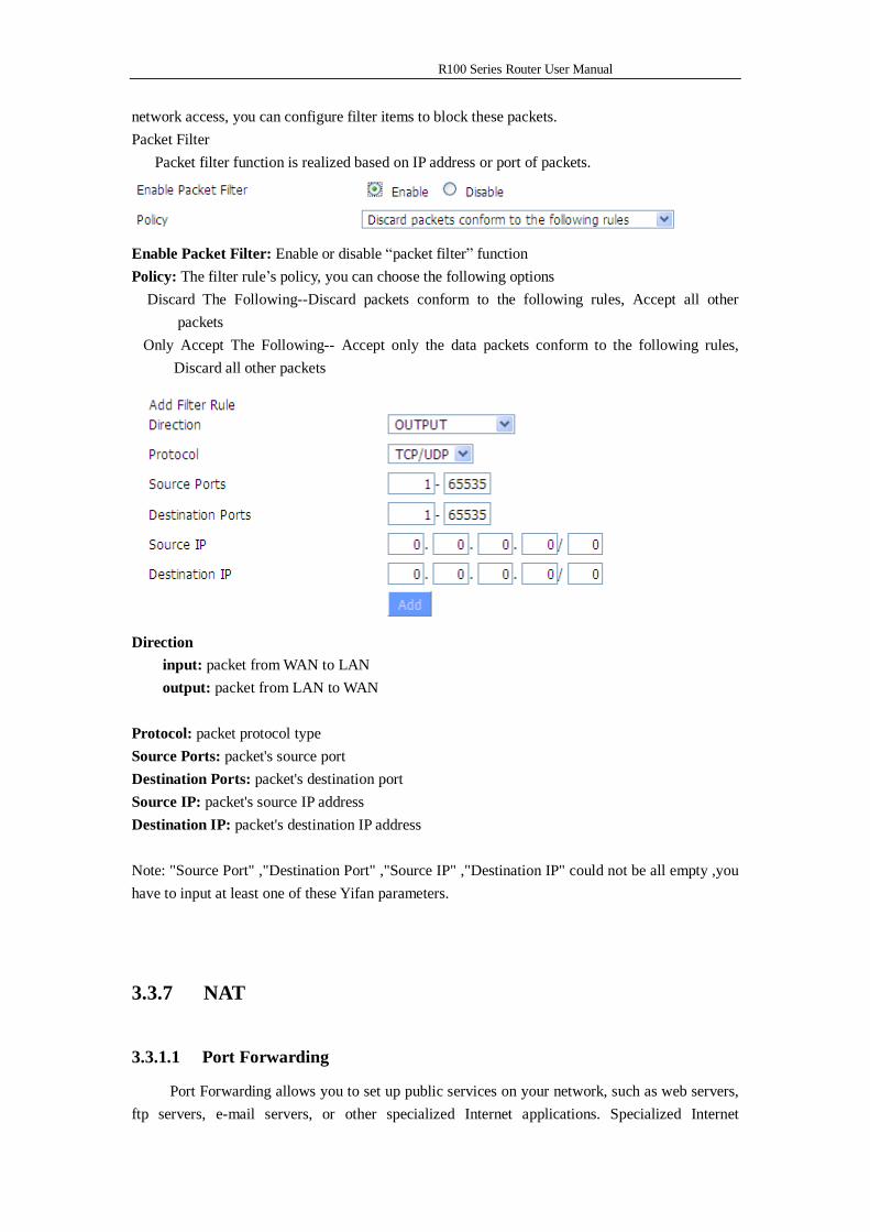
network access, you can configure filter items to block these packets. Packet Filter Packet filter function is realized based on IP address or port of packets.
Enable Packet Filter: Enable or disable “packet filter” function Policy: The filter rule’s policy, you can choose the following options Discard The Following--Discard packets conform to the following rules, Accept all other
packets Only Accept The Following-- Accept only the data packets conform to the following rules,
Discard all other packets
Direction
input: packet from WAN to LAN output: packet from LAN to WAN
Protocol: packet protocol type Source Ports: packet's source port Destination Ports: packet's destination port Source IP: packet's source IP address Destination IP: packet's destination IP address Note: "Source Port" ,"Destination Port" ,"Source IP" ,"Destination IP" could not be all empty ,you have to input at least one of these Yifan parameters.
3.3.7 NAT
3.3.1.1 Port Forwarding
Port Forwarding allows you to set up public services on your network, such as web servers, ftp servers, e-mail servers, or other specialized Internet applications. Specialized Internet
R100 Series Router User Manual
applications are any applications that use Internet access to perform functions such as videoconferencing or online gaming. When users send this type of request to your network via the Internet, the Router will forward those requests to the appropriate PC. If you want to forward a whole range of ports, see Port Range Forwarding.
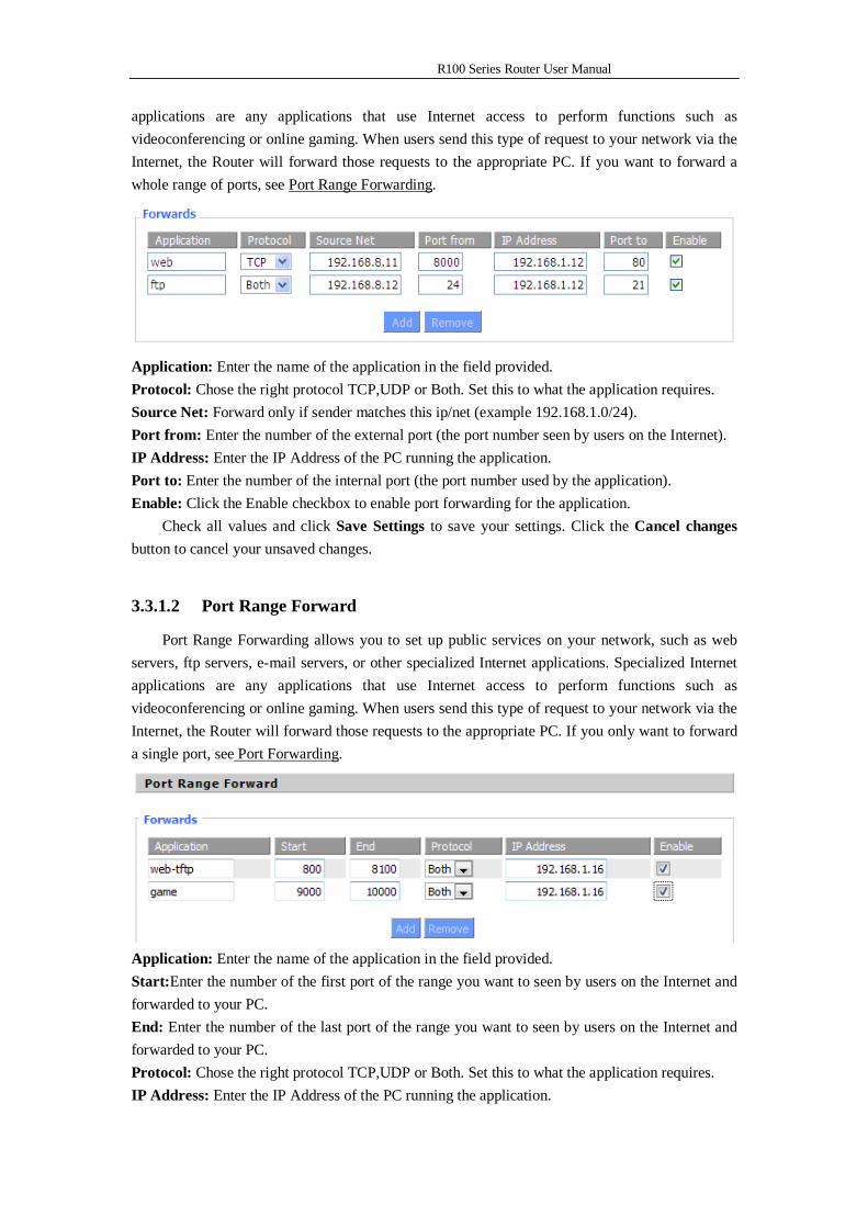
Application: Enter the name of the application in the field provided. Protocol: Chose the right protocol TCP,UDP or Both. Set this to what the application requires. Source Net: Forward only if sender matches this ip/net (example 192.168.1.0/24). Port from: Enter the number of the external port (the port number seen by users on the Internet). IP Address: Enter the IP Address of the PC running the application. Port to: Enter the number of the internal port (the port number used by the application). Enable: Click the Enable checkbox to enable port forwarding for the application.
Check all values and click Save Settings to save your settings. Click the Cancel changes button to cancel your unsaved changes.
3.3.1.2 Port Range Forward
Port Range Forwarding allows you to set up public services on your network, such as web servers, ftp servers, e-mail servers, or other specialized Internet applications. Specialized Internet applications are any applications that use Internet access to perform functions such as videoconferencing or online gaming. When users send this type of request to your network via the Internet, the Router will forward those requests to the appropriate PC. If you only want to forward a single port, see Port Forwarding.
Application: Enter the name of the application in the field provided. Start:Enter the number of the first port of the range you want to seen by users on the Internet and forwarded to your PC. End: Enter the number of the last port of the range you want to seen by users on the Internet and forwarded to your PC. Protocol: Chose the right protocol TCP,UDP or Both. Set this to what the application requires. IP Address: Enter the IP Address of the PC running the application.
R100 Series Router User Manual
Enable: Click the Enable checkbox to enable port forwarding for the application. Check all values and click Save Settings to save your settings. Click the Cancel changes
button to cancel your unsaved changes.
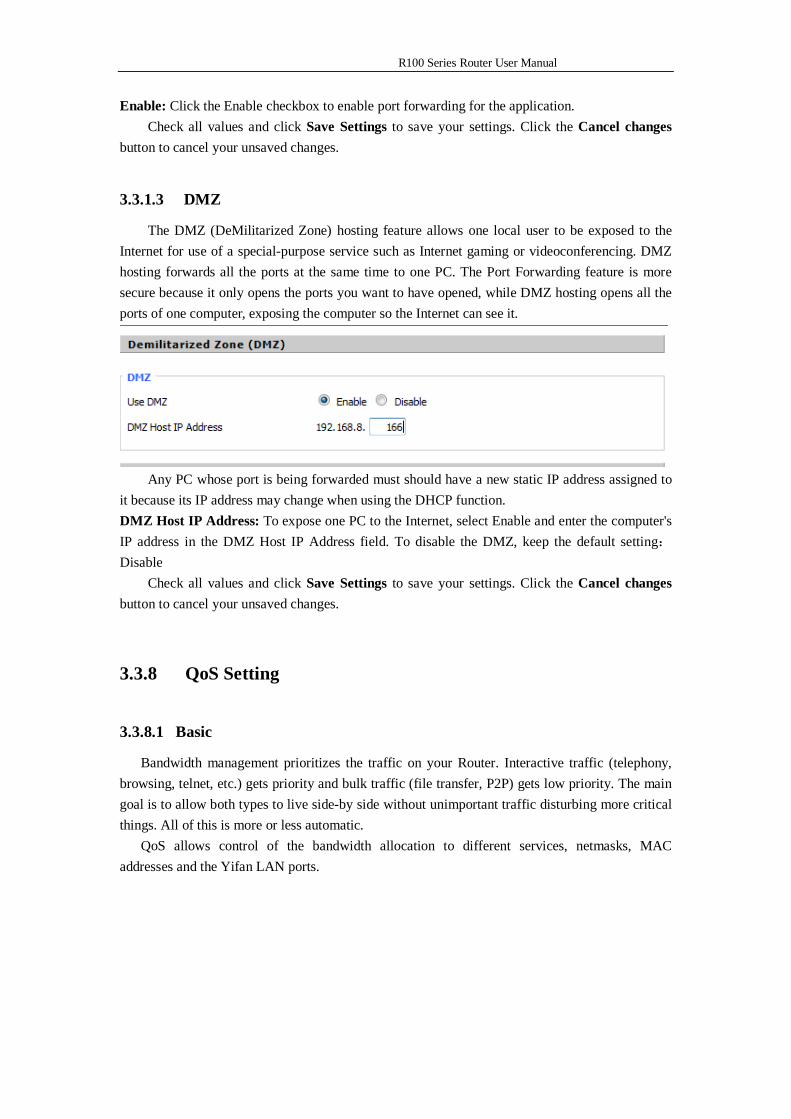
3.3.1.3 DMZ
The DMZ (DeMilitarized Zone) hosting feature allows one local user to be exposed to the Internet for use of a special-purpose service such as Internet gaming or videoconferencing. DMZ hosting forwards all the ports at the same time to one PC. The Port Forwarding feature is more secure because it only opens the ports you want to have opened, while DMZ hosting opens all the ports of one computer, exposing the computer so the Internet can see it.
Any PC whose port is being forwarded must should have a new static IP address assigned to
it because its IP address may change when using the DHCP function. DMZ Host IP Address: To expose one PC to the Internet, select Enable and enter the computer's IP address in the DMZ Host IP Address field. To disable the DMZ, keep the default setting:Disable
Check all values and click Save Settings to save your settings. Click the Cancel changes button to cancel your unsaved changes.
3.3.8 QoS Setting
3.3.8.1 Basic
Bandwidth management prioritizes the traffic on your Router. Interactive traffic (telephony, browsing, telnet, etc.) gets priority and bulk traffic (file transfer, P2P) gets low priority. The main goal is to allow both types to live side-by side without unimportant traffic disturbing more critical things. All of this is more or less automatic.
QoS allows control of the bandwidth allocation to different services, netmasks, MAC addresses and the Yifan LAN ports.
R100 Series Router User Manual
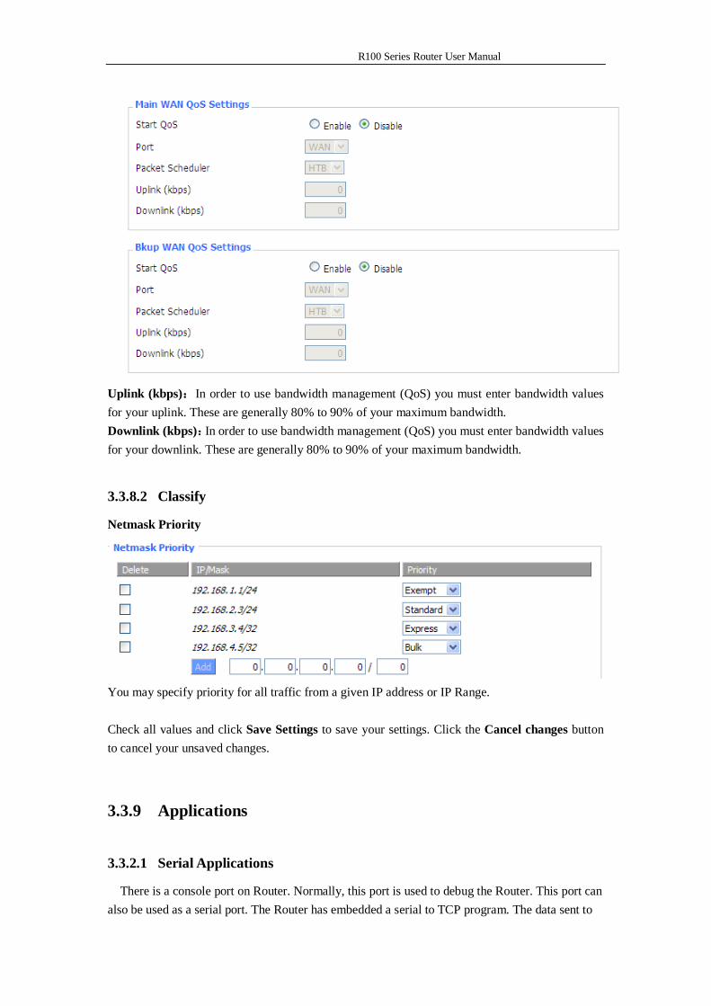
Uplink (kbps):In order to use bandwidth management (QoS) you must enter bandwidth values for your uplink. These are generally 80% to 90% of your maximum bandwidth. Downlink (kbps):In order to use bandwidth management (QoS) you must enter bandwidth values for your downlink. These are generally 80% to 90% of your maximum bandwidth.
3.3.8.2 Classify
Netmask Priority
You may specify priority for all traffic from a given IP address or IP Range. Check all values and click Save Settings to save your settings. Click the Cancel changes button to cancel your unsaved changes.
3.3.9 Applications
3.3.2.1 Serial Applications
There is a console port on Router. Normally, this port is used to debug the Router. This port can also be used as a serial port. The Router has embedded a serial to TCP program. The data sent to
R100 Series Router User Manual
the serial port is encapsulated by TCP/IP protocol stack and then is sent to the destination server. This function can work as a DTU (Data Terminal Unit).
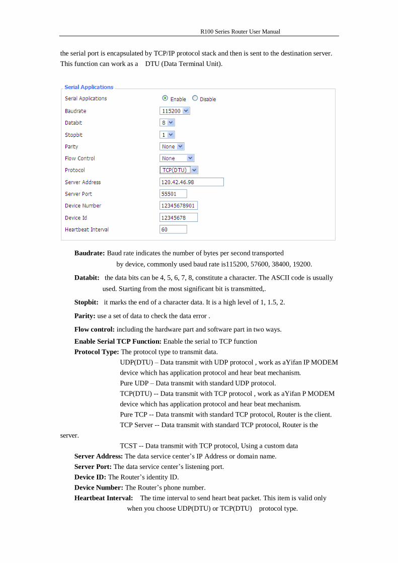
Baudrate: Baud rate indicates the number of bytes per second transported by device, commonly used baud rate is115200, 57600, 38400, 19200.
Databit: the data bits can be 4, 5, 6, 7, 8, constitute a character. The ASCII code is usually used. Starting from the most significant bit is transmitted,.
Stopbit: it marks the end of a character data. It is a high level of 1, 1.5, 2.
Parity: use a set of data to check the data error .
Flow control: including the hardware part and software part in two ways. Enable Serial TCP Function: Enable the serial to TCP function Protocol Type: The protocol type to transmit data. UDP(DTU) – Data transmit with UDP protocol , work as aYifan IP MODEM
device which has application protocol and hear beat mechanism. Pure UDP – Data transmit with standard UDP protocol.
TCP(DTU) -- Data transmit with TCP protocol , work as aYifan P MODEM device which has application protocol and hear beat mechanism.
Pure TCP -- Data transmit with standard TCP protocol, Router is the client. TCP Server -- Data transmit with standard TCP protocol, Router is the server. TCST -- Data transmit with TCP protocol, Using a custom data Server Address: The data service center’s IP Address or domain name. Server Port: The data service center’s listening port. Device ID: The Router’s identity ID. Device Number: The Router’s phone number. Heartbeat Interval: The time interval to send heart beat packet. This item is valid only
when you choose UDP(DTU) or TCP(DTU) protocol type.
R100 Series Router User Manual
TCP Server Listen Port: This item is valid when Protocol Type is “TCP Server” Custom Heartbeat Packet : This item is valid when Protocol Type is “TCST” Custom Registration Packets: This item is valid when Protocol Type is “TCST”
3.3.10 Administration
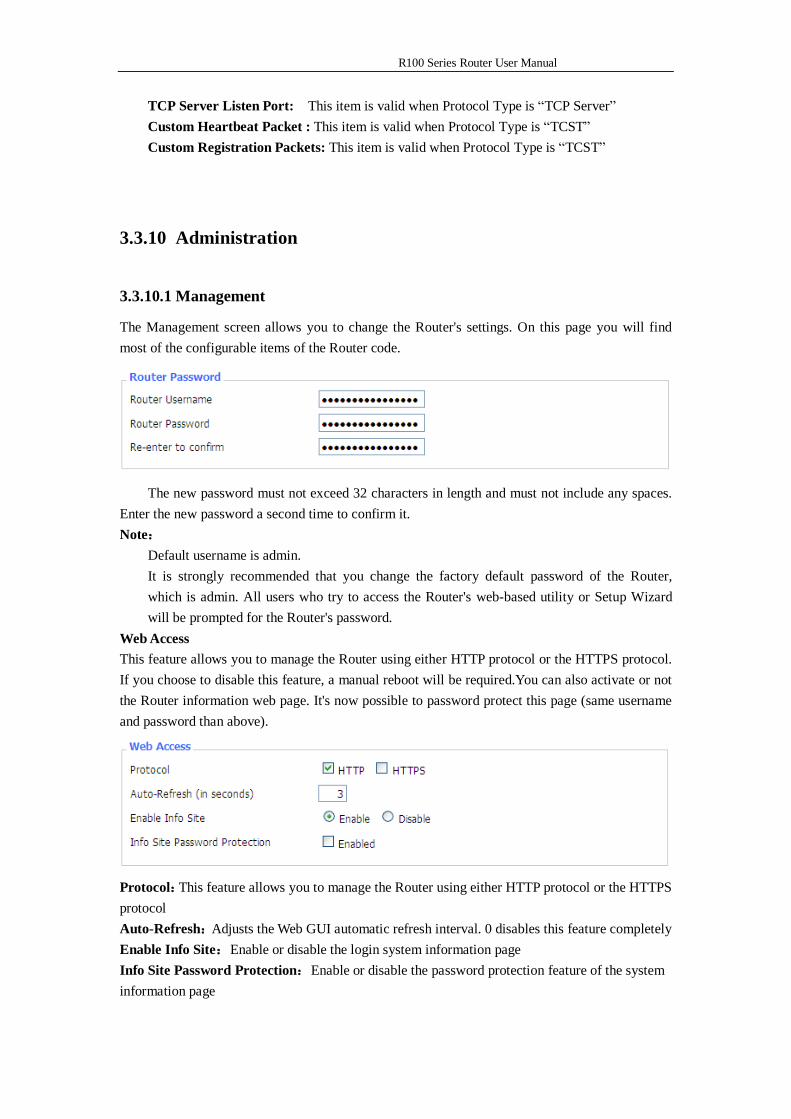
3.3.10.1 Management
The Management screen allows you to change the Router's settings. On this page you will find most of the configurable items of the Router code.
The new password must not exceed 32 characters in length and must not include any spaces. Enter the new password a second time to confirm it. Note:
Default username is admin. It is strongly recommended that you change the factory default password of the Router, which is admin. All users who try to access the Router's web-based utility or Setup Wizard will be prompted for the Router's password.
Web Access This feature allows you to manage the Router using either HTTP protocol or the HTTPS protocol. If you choose to disable this feature, a manual reboot will be required.You can also activate or not the Router information web page. It's now possible to password protect this page (same username and password than above).
Protocol:This feature allows you to manage the Router using either HTTP protocol or the HTTPS protocol Auto-Refresh:Adjusts the Web GUI automatic refresh interval. 0 disables this feature completely Enable Info Site:Enable or disable the login system information page Info Site Password Protection:Enable or disable the password protection feature of the system information page
R100 Series Router User Manual
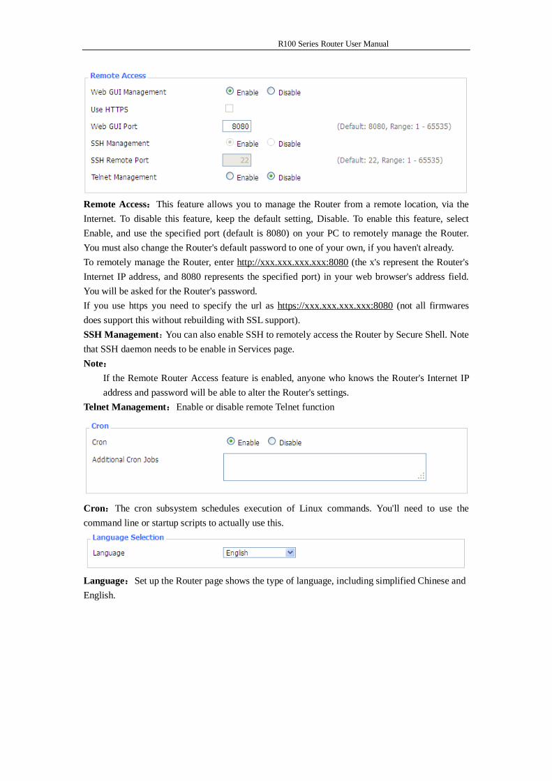
Remote Access:This feature allows you to manage the Router from a remote location, via the Internet. To disable this feature, keep the default setting, Disable. To enable this feature, select Enable, and use the specified port (default is 8080) on your PC to remotely manage the Router. You must also change the Router's default password to one of your own, if you haven't already. To remotely manage the Router, enter http://xxx.xxx.xxx.xxx:8080 (the x's represent the Router's Internet IP address, and 8080 represents the specified port) in your web browser's address field. You will be asked for the Router's password. If you use https you need to specify the url as https://xxx.xxx.xxx.xxx:8080 (not all firmwares does support this without rebuilding with SSL support). SSH Management:You can also enable SSH to remotely access the Router by Secure Shell. Note that SSH daemon needs to be enable in Services page. Note:
If the Remote Router Access feature is enabled, anyone who knows the Router's Internet IP address and password will be able to alter the Router's settings.
Telnet Management:Enable or disable remote Telnet function
Cron:The cron subsystem schedules execution of Linux commands. You'll need to use the command line or startup scripts to actually use this.
Language:Set up the Router page shows the type of language, including simplified Chinese and English.
R100 Series Router User Manual
Remote Upgrade: custom-developed remote management server for this station Router monitoring and management, configuration parameters, WIFI advertising updates.
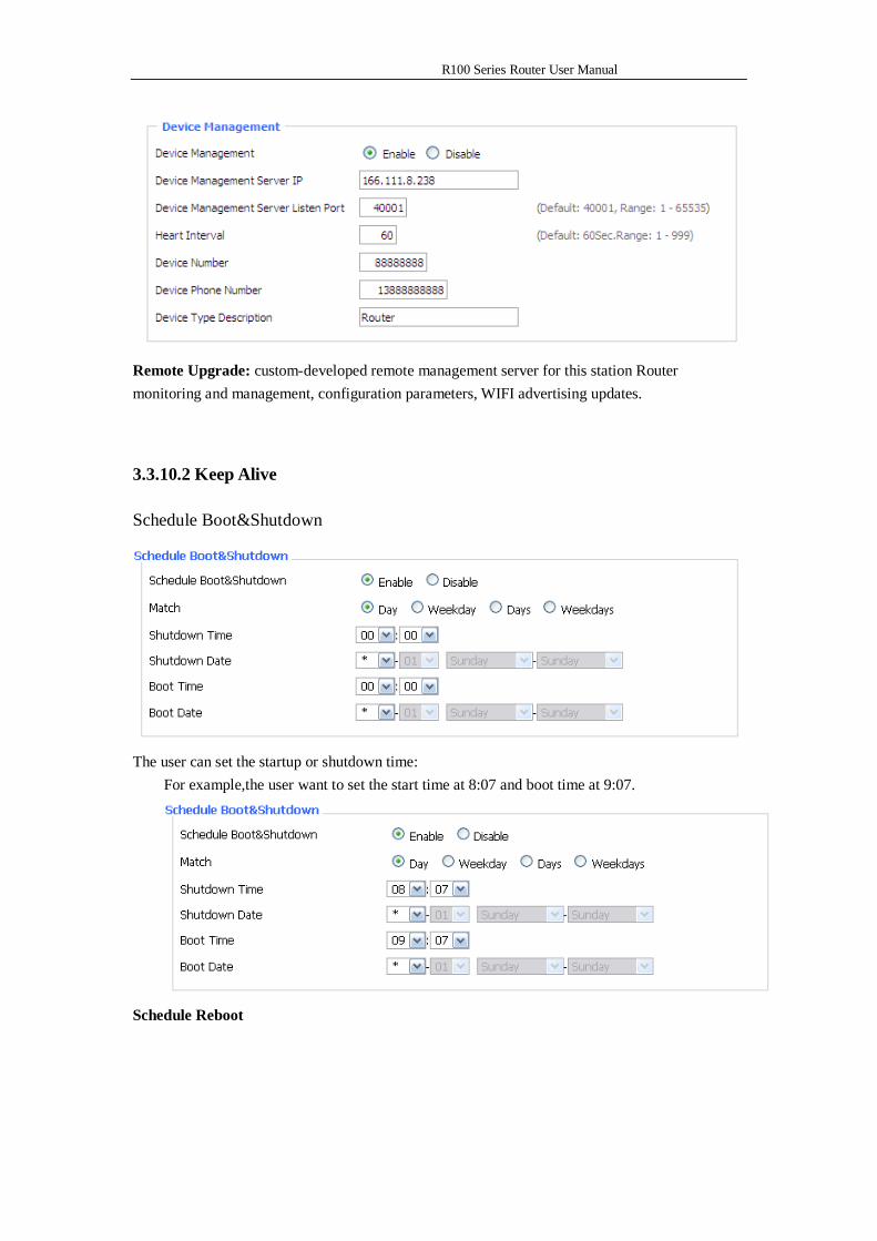
3.3.10.2 Keep Alive
Schedule Boot&Shutdown
The user can set the startup or shutdown time:
For example,the user want to set the start time at 8:07 and boot time at 9:07.
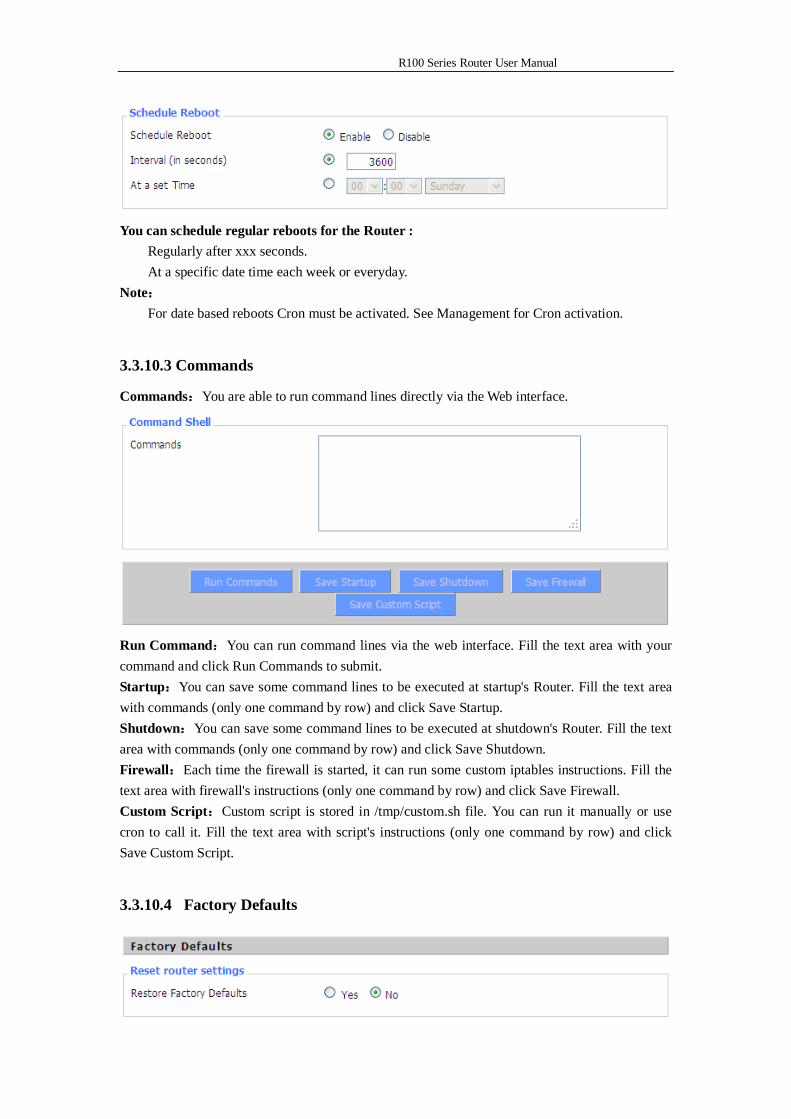
Schedule Reboot
R100 Series Router User Manual
You can schedule regular reboots for the Router :
Regularly after xxx seconds. At a specific date time each week or everyday.
Note: For date based reboots Cron must be activated. See Management for Cron activation.
3.3.10.3 Commands
Commands:You are able to run command lines directly via the Web interface.
Run Command:You can run command lines via the web interface. Fill the text area with your command and click Run Commands to submit. Startup:You can save some command lines to be executed at startup's Router. Fill the text area with commands (only one command by row) and click Save Startup. Shutdown:You can save some command lines to be executed at shutdown's Router. Fill the text area with commands (only one command by row) and click Save Shutdown. Firewall:Each time the firewall is started, it can run some custom iptables instructions. Fill the text area with firewall's instructions (only one command by row) and click Save Firewall. Custom Script:Custom script is stored in /tmp/custom.sh file. You can run it manually or use cron to call it. Fill the text area with script's instructions (only one command by row) and click Save Custom Script.
3.3.10.4 Factory Defaults
R100 Series Router User Manual
Reset Router settings:Click the Yes button to reset all configuration settings to their default values. Then click the Apply Settings button. Note:
Any settings you have saved will be lost when the default settings are restored. After restoring the Router is accessible under the default IP address 192.168.1.1 and the default password admin.
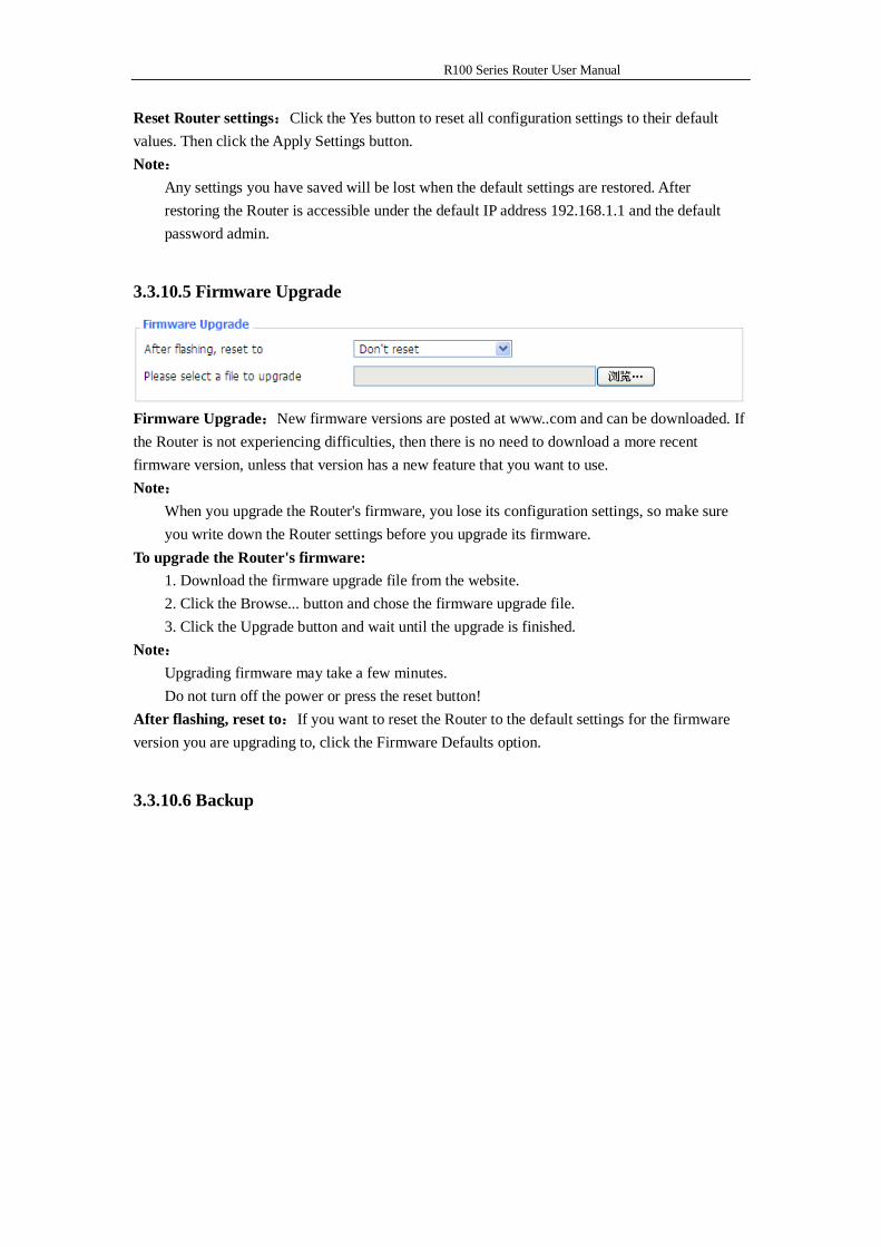
3.3.10.5 Firmware Upgrade
Firmware Upgrade:New firmware versions are posted at www..com and can be downloaded. If the Router is not experiencing difficulties, then there is no need to download a more recent firmware version, unless that version has a new feature that you want to use. Note:
When you upgrade the Router's firmware, you lose its configuration settings, so make sure you write down the Router settings before you upgrade its firmware.
To upgrade the Router's firmware: 1. Download the firmware upgrade file from the website. 2. Click the Browse... button and chose the firmware upgrade file. 3. Click the Upgrade button and wait until the upgrade is finished.
Note: Upgrading firmware may take a few minutes. Do not turn off the power or press the reset button!
After flashing, reset to:If you want to reset the Router to the default settings for the firmware version you are upgrading to, click the Firmware Defaults option.
3.3.10.6 Backup
R100 Series Router User Manual
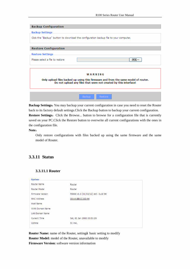
Backup Settings:You may backup your current configuration in case you need to reset the Router back to its factory default settings.Click the Backup button to backup your current configuration. Restore Settings:Click the Browse... button to browse for a configuration file that is currently saved on your PC.Click the Restore button to overwrite all current configurations with the ones in the configuration file. Note:
Only restore configurations with files backed up using the same firmware and the same model of Router.
3.3.11 Status
3.3.11.1 Router
Router Name: name of the Router, settingàbasic setting to modify Router Model: model of the Router, unavailable to modify Firmware Version: software version information
R100 Series Router User Manual
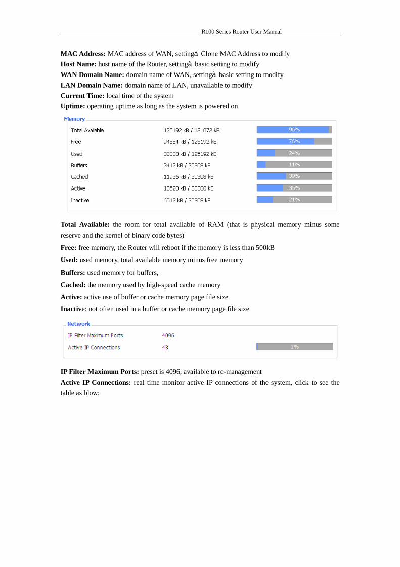
MAC Address: MAC address of WAN, settingàClone MAC Address to modify Host Name: host name of the Router, settingàbasic setting to modify WAN Domain Name: domain name of WAN, settingàbasic setting to modify LAN Domain Name: domain name of LAN, unavailable to modify Current Time: local time of the system Uptime: operating uptime as long as the system is powered on
Total Available: the room for total available of RAM (that is physical memory minus some reserve and the kernel of binary code bytes)
Free: free memory, the Router will reboot if the memory is less than 500kB
Used: used memory, total available memory minus free memory
Buffers: used memory for buffers,
Cached: the memory used by high-speed cache memory
Active: active use of buffer or cache memory page file size Inactive: not often used in a buffer or cache memory page file size
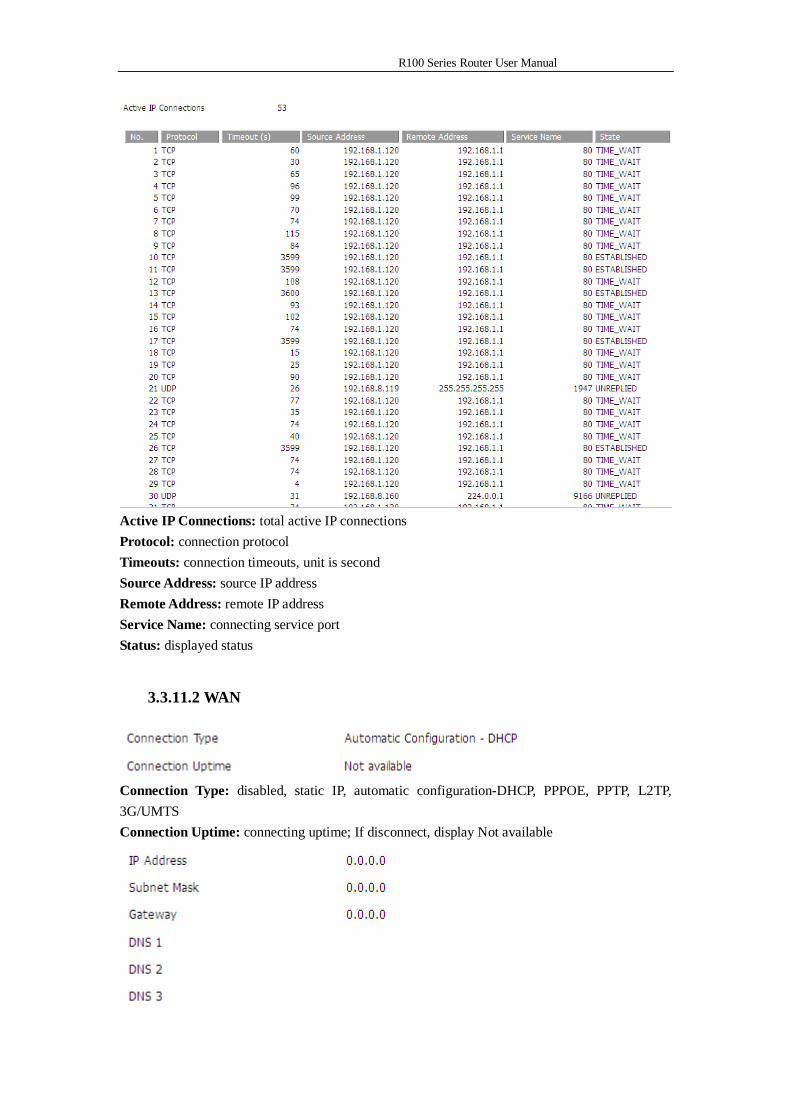
IP Filter Maximum Ports: preset is 4096, available to re-management Active IP Connections: real time monitor active IP connections of the system, click to see the table as blow:
R100 Series Router User Manual
Active IP Connections: total active IP connections Protocol: connection protocol Timeouts: connection timeouts, unit is second Source Address: source IP address Remote Address: remote IP address Service Name: connecting service port Status: displayed status
3.3.11.2 WAN
Connection Type: disabled, static IP, automatic configuration-DHCP, PPPOE, PPTP, L2TP, 3G/UMTS Connection Uptime: connecting uptime; If disconnect, display Not available
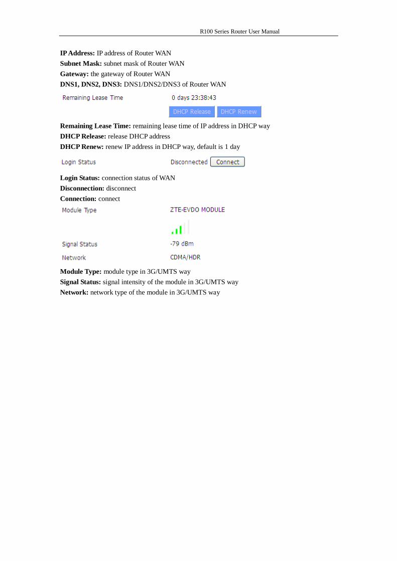
R100 Series Router User Manual
IP Address: IP address of Router WAN Subnet Mask: subnet mask of Router WAN Gateway: the gateway of Router WAN DNS1, DNS2, DNS3: DNS1/DNS2/DNS3 of Router WAN
Remaining Lease Time: remaining lease time of IP address in DHCP way DHCP Release: release DHCP address DHCP Renew: renew IP address in DHCP way, default is 1 day
Login Status: connection status of WAN Disconnection: disconnect Connection: connect
Module Type: module type in 3G/UMTS way Signal Status: signal intensity of the module in 3G/UMTS way Network: network type of the module in 3G/UMTS way
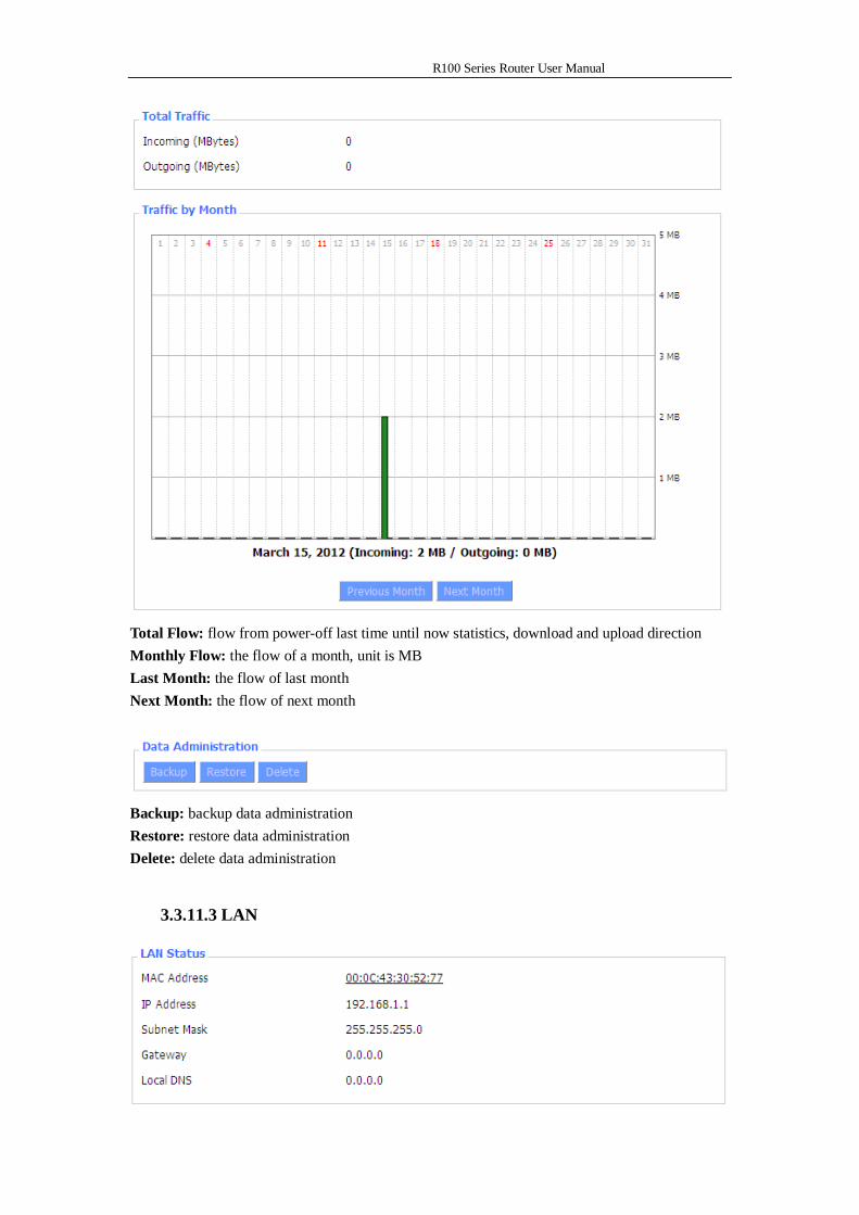
R100 Series Router User Manual
Total Flow: flow from power-off last time until now statistics, download and upload direction Monthly Flow: the flow of a month, unit is MB Last Month: the flow of last month Next Month: the flow of next month
Backup: backup data administration Restore: restore data administration Delete: delete data administration
3.3.11.3 LAN
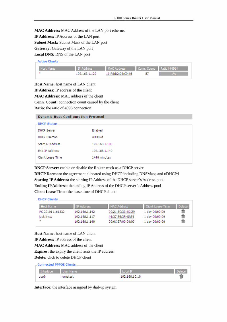
R100 Series Router User Manual
MAC Address: MAC Address of the LAN port ethernet IP Address: IP Address of the LAN port Subnet Mask: Subnet Mask of the LAN port Gateway: Gateway of the LAN port Local DNS: DNS of the LAN port
Host Name: host name of LAN client IP Address: IP address of the client MAC Address: MAC address of the client Conn. Count: connection count caused by the client Ratio: the ratio of 4096 connection
DNCP Server: enable or disable the Router work as a DHCP server DHCP Daemon: the agreement allocated using DHCP including DNSMasq and uDHCPd Starting IP Address: the starting IP Address of the DHCP server’s Address pool Ending IP Address: the ending IP Address of the DHCP server’s Address pool Client Lease Time: the lease time of DHCP client
Host Name: host name of LAN client IP Address: IP address of the client MAC Address: MAC address of the client Expires: the expiry the client rents the IP address Delete: click to delete DHCP client
Interface: the interface assigned by dial-up system
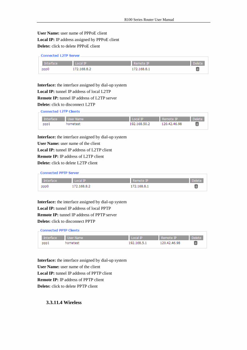
R100 Series Router User Manual
User Name: user name of PPPoE client Local IP: IP address assigned by PPPoE client Delete: click to delete PPPoE client
Interface: the interface assigned by dial-up system Local IP: tunnel IP address of local L2TP Remote IP: tunnel IP address of L2TP server Delete: click to disconnect L2TP
Interface: the interface assigned by dial-up system User Name: user name of the client Local IP: tunnel IP address of L2TP client Remote IP: IP address of L2TP client Delete: click to delete L2TP client
Interface: the interface assigned by dial-up system Local IP: tunnel IP address of local PPTP Remote IP: tunnel IP address of PPTP server Delete: click to disconnect PPTP
Interface: the interface assigned by dial-up system User Name: user name of the client Local IP: tunnel IP address of PPTP client Remote IP: IP address of PPTP client Delete: click to delete PPTP client
3.3.11.4 Wireless
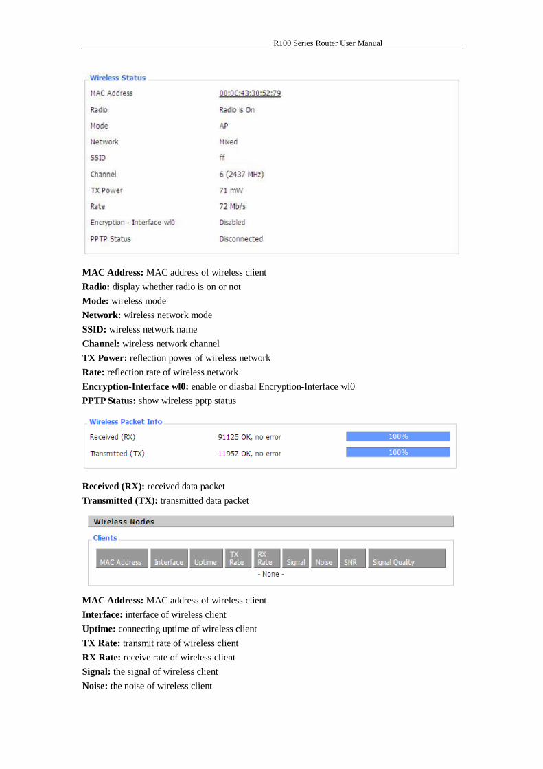
R100 Series Router User Manual
MAC Address: MAC address of wireless client Radio: display whether radio is on or not Mode: wireless mode Network: wireless network mode SSID: wireless network name Channel: wireless network channel TX Power: reflection power of wireless network Rate: reflection rate of wireless network Encryption-Interface wl0: enable or diasbal Encryption-Interface wl0 PPTP Status: show wireless pptp status
Received (RX): received data packet Transmitted (TX): transmitted data packet
MAC Address: MAC address of wireless client Interface: interface of wireless client Uptime: connecting uptime of wireless client TX Rate: transmit rate of wireless client RX Rate: receive rate of wireless client Signal: the signal of wireless client Noise: the noise of wireless client
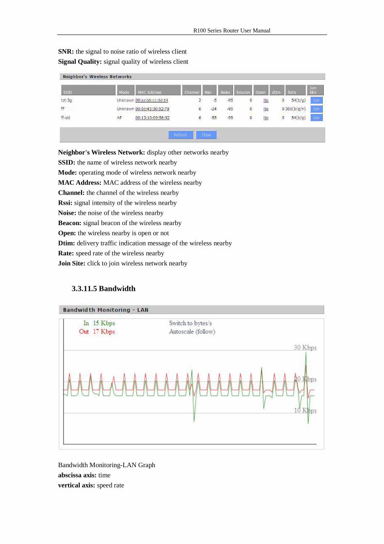
R100 Series Router User Manual
SNR: the signal to noise ratio of wireless client Signal Quality: signal quality of wireless client
Neighbor's Wireless Network: display other networks nearby SSID: the name of wireless network nearby Mode: operating mode of wireless network nearby MAC Address: MAC address of the wireless nearby Channel: the channel of the wireless nearby Rssi: signal intensity of the wireless nearby Noise: the noise of the wireless nearby Beacon: signal beacon of the wireless nearby Open: the wireless nearby is open or not Dtim: delivery traffic indication message of the wireless nearby Rate: speed rate of the wireless nearby Join Site: click to join wireless network nearby
3.3.11.5 Bandwidth
Bandwidth Monitoring-LAN Graph abscissa axis: time vertical axis: speed rate
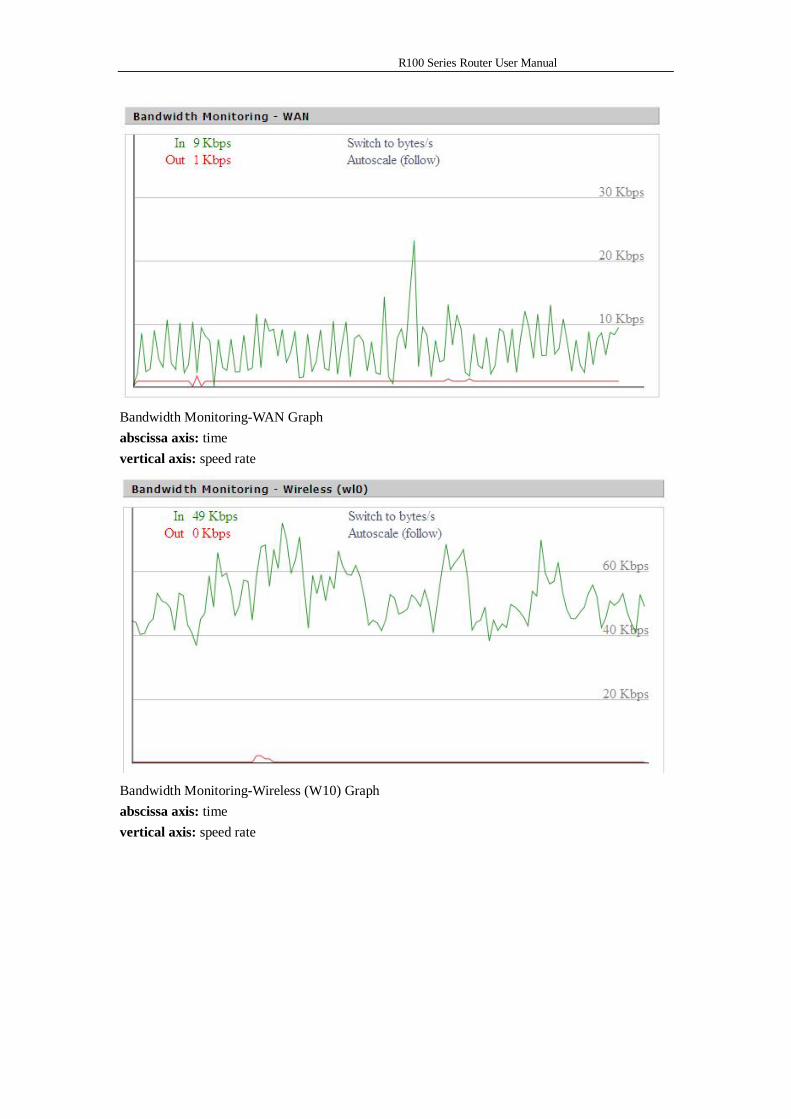
R100 Series Router User Manual
Bandwidth Monitoring-WAN Graph abscissa axis: time vertical axis: speed rate
Bandwidth Monitoring-Wireless (W10) Graph abscissa axis: time vertical axis: speed rate
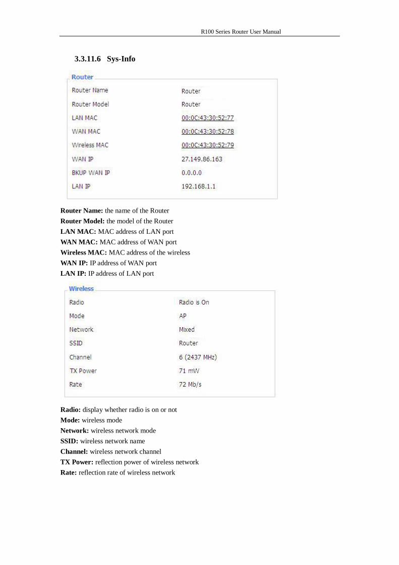
R100 Series Router User Manual
3.3.11.6 Sys-Info
Router Name: the name of the Router Router Model: the model of the Router LAN MAC: MAC address of LAN port WAN MAC: MAC address of WAN port Wireless MAC: MAC address of the wireless WAN IP: IP address of WAN port LAN IP: IP address of LAN port
Radio: display whether radio is on or not Mode: wireless mode Network: wireless network mode SSID: wireless network name Channel: wireless network channel TX Power: reflection power of wireless network Rate: reflection rate of wireless network
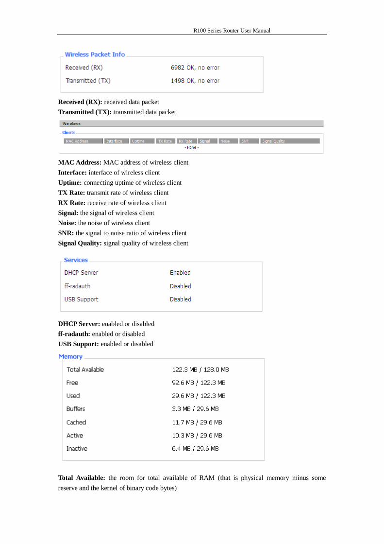
R100 Series Router User Manual
Received (RX): received data packet Transmitted (TX): transmitted data packet
MAC Address: MAC address of wireless client Interface: interface of wireless client Uptime: connecting uptime of wireless client TX Rate: transmit rate of wireless client RX Rate: receive rate of wireless client Signal: the signal of wireless client Noise: the noise of wireless client SNR: the signal to noise ratio of wireless client Signal Quality: signal quality of wireless client
DHCP Server: enabled or disabled ff-radauth: enabled or disabled USB Support: enabled or disabled
Total Available: the room for total available of RAM (that is physical memory minus some reserve and the kernel of binary code bytes)
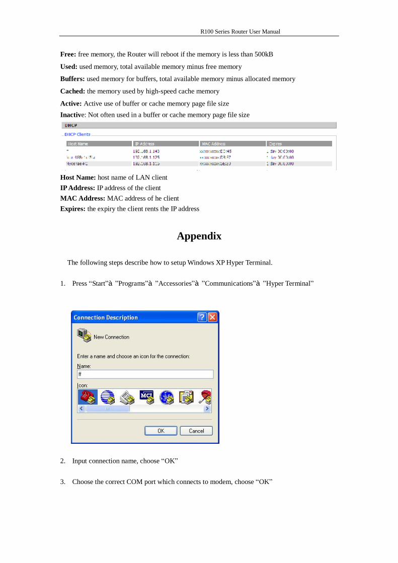
R100 Series Router User Manual
Free: free memory, the Router will reboot if the memory is less than 500kB
Used: used memory, total available memory minus free memory
Buffers: used memory for buffers, total available memory minus allocated memory
Cached: the memory used by high-speed cache memory
Active: Active use of buffer or cache memory page file size Inactive: Not often used in a buffer or cache memory page file size
Host Name: host name of LAN client IP Address: IP address of the client MAC Address: MAC address of he client Expires: the expiry the client rents the IP address
Appendix
The following steps describe how to setup Windows XP Hyper Terminal.
1. Press “Start”à”Programs”à”Accessories”à”Communications”à”Hyper Terminal”
2. Input connection name, choose “OK”
3. Choose the correct COM port which connects to modem, choose “OK”
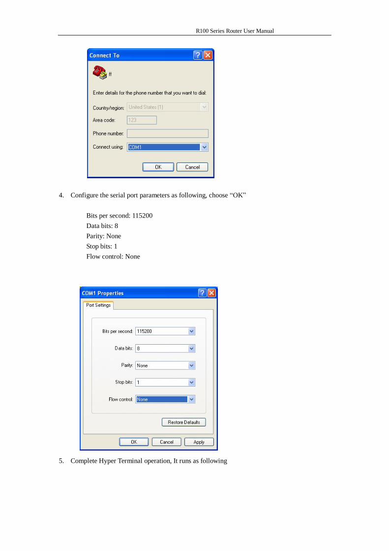
R100 Series Router User Manual
4. Configure the serial port parameters as following, choose “OK”
Bits per second: 115200 Data bits: 8 Parity: None Stop bits: 1 Flow control: None
5. Complete Hyper Terminal operation, It runs as following
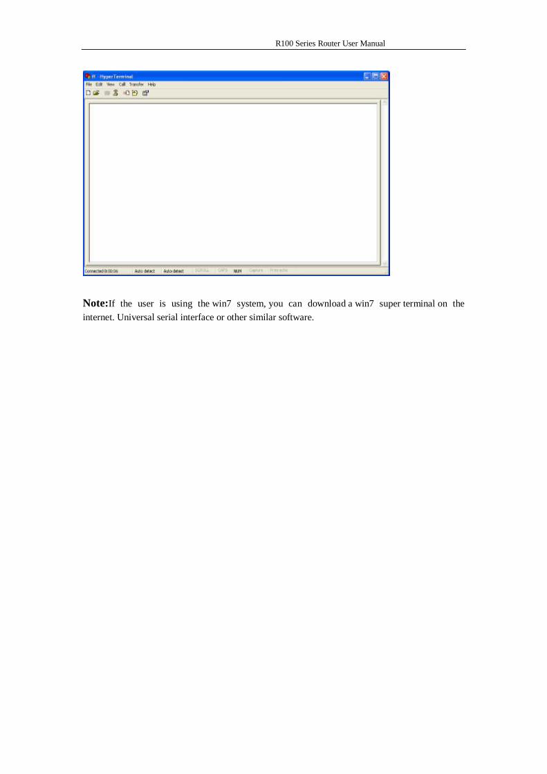
R100 Series Router User Manual
Note:If the user is using the win7 system, you can download a win7 super terminal on the internet. Universal serial interface or other similar software.