Embed Size (px)
Citation preview

7/17/2019 R05323-P-001A-X009-0042.pdf
http://slidepdf.com/reader/full/r05323-p-001a-x009-0042pdf 1/463
P-001A X009 0042 1
7689
4 NA 06/26/12

7/17/2019 R05323-P-001A-X009-0042.pdf
http://slidepdf.com/reader/full/r05323-p-001a-x009-0042pdf 2/463
INDEX
Item No. Description
1 Datasheets (Pump & Motor), Performance Curve
2 Installation Drawing
3 Assembly Drawing
4 Lifting Diagram
5 ITP
6 Ultrasonic Flaw Detection Specification For Shaft Parts
7 Welding Process Specification
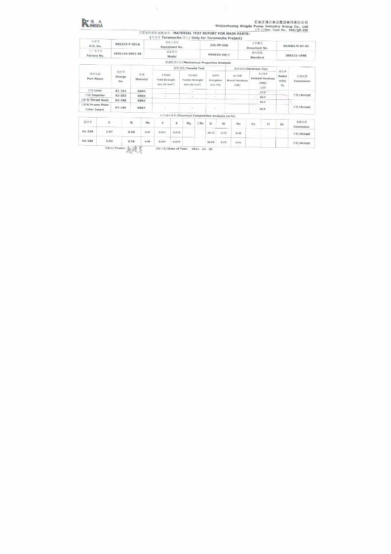
8 Material Report For Main Parts
9 Ultrasonic Flaw Detection Report
10 Inspection Report For Parts
11 Inspection Record For Assembly
12 Inspection Record For Painting
13 Inspection Record For Packing
14 Hydraulic Pressure Test Report
15 Performance Test Procedure
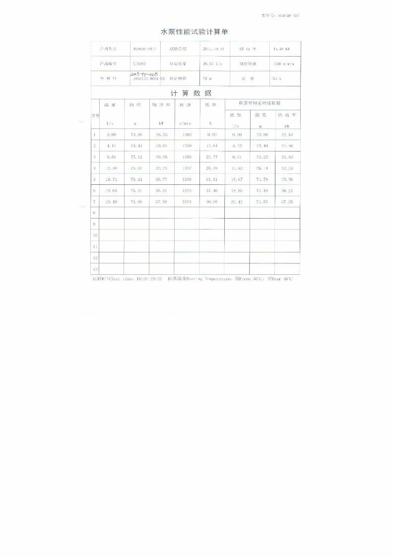
16 Performance Test Details Sheet
17 Performance Test Report
18 Vibration Report
19 Noise Report
20 Pump IOM
21 Motor IOM
22 Long Term Storage Instructions
23 Spare Parts List for Operation and 1 Year (Un-priced)
24 Pump Lubrication Schedule
25 Motor Lubrication Schedule
26 Packing List
27 Certification of Conformance
28 Motor Wiring Diagram

7/17/2019 R05323-P-001A-X009-0042.pdf
http://slidepdf.com/reader/full/r05323-p-001a-x009-0042pdf 3/463
7/17/2019 R05323-P-001A-X009-0042.pdf
http://slidepdf.com/reader/full/r05323-p-001a-x009-0042pdf 4/463

7/17/2019 R05323-P-001A-X009-0042.pdf
http://slidepdf.com/reader/full/r05323-p-001a-x009-0042pdf 5/463

7/17/2019 R05323-P-001A-X009-0042.pdf
http://slidepdf.com/reader/full/r05323-p-001a-x009-0042pdf 6/463

7/17/2019 R05323-P-001A-X009-0042.pdf
http://slidepdf.com/reader/full/r05323-p-001a-x009-0042pdf 7/463

7/17/2019 R05323-P-001A-X009-0042.pdf
http://slidepdf.com/reader/full/r05323-p-001a-x009-0042pdf 8/463

7/17/2019 R05323-P-001A-X009-0042.pdf
http://slidepdf.com/reader/full/r05323-p-001a-x009-0042pdf 9/463

7/17/2019 R05323-P-001A-X009-0042.pdf
http://slidepdf.com/reader/full/r05323-p-001a-x009-0042pdf 10/463
7/17/2019 R05323-P-001A-X009-0042.pdf
http://slidepdf.com/reader/full/r05323-p-001a-x009-0042pdf 11/463

7/17/2019 R05323-P-001A-X009-0042.pdf
http://slidepdf.com/reader/full/r05323-p-001a-x009-0042pdf 12/463
7/17/2019 R05323-P-001A-X009-0042.pdf
http://slidepdf.com/reader/full/r05323-p-001a-x009-0042pdf 13/463
7/17/2019 R05323-P-001A-X009-0042.pdf
http://slidepdf.com/reader/full/r05323-p-001a-x009-0042pdf 14/463
No. 239, Tianshan Street, Shijiazhuang City, Hebei Province, ChinaTel: +86 311 80908109 Fax: +86 311 80908116 Email: [email protected]
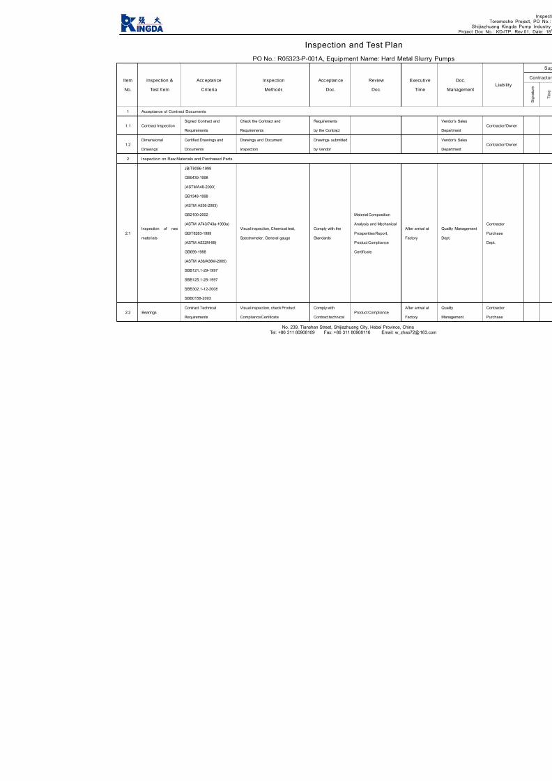
Inspection and Test Plan
PO No.: R05323-P-001A, Equipment Name: Hard Metal Slurry Pumps
Item
No.
Inspection &
Test Item
Acc eptance
Criteria
Inspection
Methods
Acceptance
Doc.
Review
Doc.
Executive
Time Ma
1 Acceptance of Contract Documents
1.1 Contract Inspection
Signed Contract and
Requirements
Check the Contract and
Requirements
Requirements
by the Contract
Vendor
Departm
1.2
Dimensional
Drawings
Certified Drawings and
Documents
Drawings and Document
Inspection
Drawings submitted
by Vendor
Vendor
Departm
2 Inspectio n on Raw Materials and Purchased Parts
2.1
Inspection of raw
materials
JB/T8096-1998
GB9439-1998
(ASTM A48-2003)
GB1348-1998
(ASTM A536-2003)
GB2100-2002
(ASTM A743/743a-1993a)
GB/T8263-1999
(ASTM A532M-99)
GB699-1988
(ASTM A36/A36M-2005)
SBB121.1-29-1997
SBB125.1-28-1997
SBB302.1-12-2008
SBB0158-2003
Visual inspection, Chemical test,
Spectrometer, General gauge
Comply with the
Standards
Material Composition
Analysis and Mechanical
Prosperities Report,
Product Compliance
Certificate
After arrival at
Factory
Quality
Dept.
2.2 Bearings
Contract Technical
Requirements
Visual inspection, check Product
Compliance Certificate
Comply with
Contract technical
Product Compliance
After arrival at
Factory
Quality
Manage

7/17/2019 R05323-P-001A-X009-0042.pdf
http://slidepdf.com/reader/full/r05323-p-001a-x009-0042pdf 15/463
No. 239, Tianshan Street, Shijiazhuang City, Hebei Province, ChinaTel: +86 311 80908109 Fax: +86 311 80908116 Email: [email protected]
requirement Dept.
2.3 WEG Motors
Contract Technical
Requirements
Visual inspection, check Product
Compliance Certificate
Comply with
Contract technical
requirement
Product Compliance
After arrival at
Factory
Quality
Manage
Dept.
3 Inspectio n and Test in Pump Product ion Process
3.1
Inspection Before
Casting
SBB139-2001
SBB131-1998
SBB122-2000
Spectrometer
Comply with the
Standards
Material Composition
Analysis and Mechanical
Prosperities Report
Before Pouring
Quality
Manage
Dept.
3.2 Castings
SBB139-2001
SBB122-2000
SBB131-1998
GB1348-1988
(ASTM A536-2003)
Spectrometer,
Carbon-Sulfur Analyzer,
Chemical Test, General Gauge
Comply with the
Standards
Material Composition
Analysis and Mechanical
Prosperities Report
After
heat treatment
Quality
Dept.
3.3 Heat TreatmentSBB131-1998
SBB165-2009
Hardness Tester,
Universal Tester
Comply with the
Standards
Heat Treatment
Report
After
heat treatment
Quality
Manage
Dept.
3.4
Inspection in
Machining Process
SBB2105-87
SBB061-2003
Drawing Requirements
General Tools,
Special Tools
Comply with the
Standards and
Drawing
Requirements
Machining Dimension
Inspection Record
During
Machining
Process
Quality
Manage
Dept.
3.5
Impeller Static
Balancing,
SBB061-2003 Balancing Test Frame
Comply with the
Standard
Impeller Static Blancing
Report
Static Balance
Test
Quality
Manage
Dept.
3.6 Shafft Inspection YB-T036.T-92 Ultrasonic Detection
Comply with the
Standard
Shaft Ultrasonics
Detection Report
Shaft Inspection
Test
Quality
Manage
Dept.
4 Assembl y, Test, Painting and Packing
4.1 Assembly SBB2103-2000 General Gauge
Comply with the
Standards and
Clearance Inspection
Record in Assembly
After Assembly
Quality
Dept.

7/17/2019 R05323-P-001A-X009-0042.pdf
http://slidepdf.com/reader/full/r05323-p-001a-x009-0042pdf 16/463
No. 239, Tianshan Street, Shijiazhuang City, Hebei Province, ChinaTel: +86 311 80908109 Fax: +86 311 80908116 Email: [email protected]
SBB064-2004
Drawing Requirements
Drawing
Requirements
4.2
Hydraulic
Pressure Test
GB/T5656-94,
SBB064-1998,
(HI 1.6-2000/API610)
Visual Inspection,
Pressure gauge
Comply with the
standards
Hydraulic Pressure Test
Report
After Assembly,
Witness Point
Quality
Dept.
4.3
Performance
Noise
Vibration
Contract Technical
Requirements
GB3216-2005
(HI 1.6-2000/
ASME B73.1M/B73.2M)
JB/T8097-1999
GB3214-91,
GB10890,
GB10889
SBB064-2004
Pump Test Station
Comply with the
Standards and
Contract Technical
Requirements
Pump Performance
Running Test Report
After Assembly,
Witness Point
Quality
Dept.
4.4 Painting
Contract Technical
Requirements SBB097-2008
SBB0159-1998
JB/T4297-1992
Visual Inspection,
Coating Thickness Meter
Comply with the
Standards and
Contract Technical
Requirements
Assembly Inspection
Record
After Painting
Quality
Dept.
4.5 Packing
Contract Technical
Requirements
SBB0157-1997
SBB0167-2009
GB/T13384-1992
Visual Inspection
Comply with the
Standards and
Contract Technical
Requirements
Assembly Inspection
Record
After Packing
Quality
Dept.
5 Relese for Shippment
5.1
Release for
shipment
Contract requirements As per Contract Requirements
Release for
shipment from
Owner
Hold Point

7/17/2019 R05323-P-001A-X009-0042.pdf
http://slidepdf.com/reader/full/r05323-p-001a-x009-0042pdf 17/463
ULTRASONIC FLAW DETECTION
SPECIFICATION
FOR
SHAFT PARTS
TOROMOCHO PROJECT
Supplier: SHIJIAZHUANG KINGDA PUMP INDUSTRY GROUP CO., LTD
Reviewed And Approved:
Date: November, 2011

7/17/2019 R05323-P-001A-X009-0042.pdf
http://slidepdf.com/reader/full/r05323-p-001a-x009-0042pdf 18/463
SHIJIAZHUANG KINGDA PUMP INDUSTRY GROUP CO., LTDULTRASONIC FLAW DETECTION SPECIFICATIONDoc No.: WPS-UD-2011, Date: Nov, 2011, Rev 00
NO. 239, TIANSHAN STREET, SHIJIAZHUANG CITY, HEBEI PROVINCE, CHINA
GENERAL TECHNICAL SPECIFICATION
FOR ULTRASONIC FLAW DETECTIOIN FOR SHAFT PARTS
1. General Provision
1.1 Application Scope
This Specification applies for the testing of internal incontinuity of forgings sourced by Kingda by using A
Type Pulse Reflection Ultrasonic Detection method.
This Specification is not applied to work piece of austenite coarse grained.
1.2 Acceptance Standard
GB/T 4162 Forged And Rolled Steel Bars - Method For Ultrasonic Testing
GB/T 7736 Ultrasonic Inspecting Method For Macro-Structure And Imperfection Of Steel
1.3 If special requirements, inspection and acceptance will be carried as per Standards in relative
agreements, drawing and process.
1.4 Requirements for Inspectors
The inspectors should have Ultrasonic Flaw Detection Technology Certification, and the Inspector who will
sign the Report must be qualified for II Grade or Above Certification.
2. Detection Equipment And Instruments
2.1 Ultrasonic Flaw Detector
The ultrasonic flaw detector should be tested for its fuction as per the methods specified in JB/T
10061-1999, and its quota should be meet following:
a). Surplus Sensitivity: N≥36dB
b). Vertical Linearity Tolerance: D≤6%
c). Horizontal Linearity Tolerance: δ≤1%
d). Dynamic Range: ≥30dB.
2.2 Probe
Usually straight beam probe is selected for detection; angle beam probe is selected for assistant detection.
The operation frequency of probe must meet the requirements to penetrate and explore the work piece,
nominal frequency of 2-5MHz is used, and probe crystal diameter or side length is 10-25mm.
2.3 Coupling Medium
Coupling medium whichever can give good coupling effect and is not harmful to body and work piece
should be selected.
The same coupling medium must be used for adjustment, calibration and inspection of equipments.

7/17/2019 R05323-P-001A-X009-0042.pdf
http://slidepdf.com/reader/full/r05323-p-001a-x009-0042pdf 19/463
SHIJIAZHUANG KINGDA PUMP INDUSTRY GROUP CO., LTDULTRASONIC FLAW DETECTION SPECIFICATIONDoc No.: WPS-UD-2011, Date: Nov, 2011, Rev 00
NO. 239, TIANSHAN STREET, SHIJIAZHUANG CITY, HEBEI PROVINCE, CHINA
2.4 Test Block
When test forged parts, the test block should be selected according to probe and condition of surface to be
detected, for example, CSI standard test block.
Equipment can also be adjusted according to test block as per GB/T 4162 or GB/T 7736.
3. Detection
3.1 Detection Method
Detection method is generally P-wave reflection, SH-wave reflection can be added if necessary.
A: Necessary detecting direction
B: Detecting direction which needs to be negotiated
Detection At Axial And Circumferential Direction For Shaft Parts
3.2 Detection Time
Usually the detection should be carried after entry of source parts into plant or after heat treatment.
If there any special requirements, the detection should be carried as per special time.
3.3 Detection Procedure
3.3.1 Treatment on Surface of Work Piece
Usually the roughness of surface of work piece should be R0≤6.3μm; Roughness may be enlarged for
coarse surface, but not more than 12.5μm.
The flaws as mill scale, dirties, paint and pit which can influence the acoustic coupling must be removed or
machined.
3.3.2 Adjustment of Instrument
3.3.2.1 Adjustment of Scan Speed
Generally it is required that forward base of first bottom wave should be not more than 80% of width of
oscilloscope screen in order to observe the situation of other signals after first bottom wave.
3.3.2.2 Adjustment of Sustained Sensitivity
For the work piece with thickness of position tested ≥3N, bottom wave adjustment method can be used;
For the work piece with thickness of position tested <3N or the surface is very rough, test pad adjustment

7/17/2019 R05323-P-001A-X009-0042.pdf
http://slidepdf.com/reader/full/r05323-p-001a-x009-0042pdf 20/463
SHIJIAZHUANG KINGDA PUMP INDUSTRY GROUP CO., LTDULTRASONIC FLAW DETECTION SPECIFICATIONDoc No.: WPS-UD-2011, Date: Nov, 2011, Rev 00
NO. 239, TIANSHAN STREET, SHIJIAZHUANG CITY, HEBEI PROVINCE, CHINA
method can be used.
When the surface shape and roughness of test pad is different from the work piece, coupling compensation
and attenuation compensation methods can be used.
3.3.2.3 Adjustment of Scan Sensitivity
6dB should be amplified based on the inspection sensitivity in order to easily find the defects, but estimation
on the defects should be based on the inspection sensitivity level.
3.4 Inspection Frequency
3.4.1 If no special requirement, the sample test should be made as per SBB302.1-2008.
3.4.2 If any special requirements, the test should be made as per requirements.
3.4.3 For the tested work piece, whole detecting should be made.
3.5 Scan Detection
3.5.1 Scan Type
Usually whole scan should be used.
3.5.2 Scan Speed
In order to ensure the defects can be clearly found, the scan speed should not more than 150mm/s.
3.5.3 Scan Distance
It is required that 15% overlapping should be done between two scans.
3.6 Calibration of Instruments
After detection, the instrument should be calibrated for sensitivity; if the sensitivity can not meet the
requirements, calibration should be done.
4. Estimation of Defects
Usually defects will be estimated according to the reflection and bottom reflection results, including defect
position and size, if necessary, the nature of defects can be estimated.
4.1 Estimation of Defect Position
To determine the surface position of defect according to the probe work position;
To determine he depth of defects according to that tested in oscilloscope screen.
4.2 Estimation of Defect Size
4.2.1 For flat defect of small wafer size, equivalent size of defect should be estimated according to the echo
margin shown in oscilloscope screen.
4.2.2 For flat defect of large wafer size, the length and area of defect should be estimated by 6dB or half
wave height method.

7/17/2019 R05323-P-001A-X009-0042.pdf
http://slidepdf.com/reader/full/r05323-p-001a-x009-0042pdf 21/463
SHIJIAZHUANG KINGDA PUMP INDUSTRY GROUP CO., LTDULTRASONIC FLAW DETECTION SPECIFICATIONDoc No.: WPS-UD-2011, Date: Nov, 2011, Rev 00
NO. 239, TIANSHAN STREET, SHIJIAZHUANG CITY, HEBEI PROVINCE, CHINA
4.2.3 For the defect of volume type, circumferential direction detection method can be used.
5. Quality Estimation
Estimation should be made as per GB/T 4162 and GB/T 7736; if any, special requirements can be followed.
After the detection, if disputes, it can be confirmed by low-power etch test.
6. Inspection Record And Report
6.1 Inspection report include: specification, grade, heat number, standard, quality grade and quantity,
issued by who and date, etc.
6.2 Inspection record should include position of defect, size of equivalent, distance and length of defects,
and drop of bottom wave, etc.

7/17/2019 R05323-P-001A-X009-0042.pdf
http://slidepdf.com/reader/full/r05323-p-001a-x009-0042pdf 22/463

7/17/2019 R05323-P-001A-X009-0042.pdf
http://slidepdf.com/reader/full/r05323-p-001a-x009-0042pdf 23/463
SHIJIAZHUANG KINGDA PUMP INDUSTRY GROUP CO., LTD
WELDING PROCESS SPECIFICATION FOR REPAIR OF CASTINGS
Doc No.: WPS-KD-2011, Date: Oct, 2011, Rev 00
NO. 239, TIANSHAN STREET, SHIJIAZHUANG CITY, HEBEI PROVINCE, CHINA
Process Specification of Welding
1. Preparation Before Welding
1.1 Operator must be very well acquainted with the drawings, process specification and relative
documents.
1.2 Operator must carefully check the material grades and dimensions of parts and casting
which are going to be welded.
1.3 Calibers and scales must be marked with inspection certificate. The tools and auxiliary
devices must be reliable.
1.4 The welding machine must be in good condition, grounding and good in insulation.
1.5 Select welding materials as per specification.
1.6 Welding rods must be complete dry, if the rods are wet, make dry treatment as following
table:
Dry Methods for Welding Rod
Type of Rod Dry Temperature () Dry Time (hour)
acid-type 70~150 1~1.5
alkaline-type 250~350 1~2
Note: usually, the acid rod may not be dried before using, the alkaline rod (including S.S. rod) must be dried
treatment before using.
2. Welding
2.1 Clear water, oil stain, rust and burrs within 20mm to 30mm at two sides of weld seam and
bevel before welding.
2.2 For the parts to be beveled, the shape and dimension of bevel should conform to GB985-88
Standard.
2.3 Select welding rod as following Specification Table:
Selection of Welding Rod
Thickness of Welding Part (mm) Diameter of Rod (mm)
≤4
4~12
>12
≤3.2
3.2~4.0
≥4.0
2.4 Welding Current Selection of Common Welding Rod as following:
Reference Current (A)

7/17/2019 R05323-P-001A-X009-0042.pdf
http://slidepdf.com/reader/full/r05323-p-001a-x009-0042pdf 24/463
SHIJIAZHUANG KINGDA PUMP INDUSTRY GROUP CO., LTD
WELDING PROCESS SPECIFICATION FOR REPAIR OF CASTINGS
Do .: WPS-KD-2011, Date: Oct, 2011, Rev 00
NO. 239, TIANSHAN STREET, SHIJIAZHUANG CITY, HEBEI PROVINCE, CHINA
c No
Rod Dia.
(mm)
Welding Grade
2.5 3.2 4.0 5.0
E4303 70~90 90~130 160~220 220~270
E4303 70~90 90~130 160~190 180~230
Note: upper limit for thick plate; the current of horizontal welding is about 10% less than downward welding.
2.5 General Principle for Welding Procedure
2.5.1 It must not produce rigid constraint force against the others of welding seam at the
beginning welding.
2.5.2 One end of each seam should be kept shrink freely at welding.
2.5.3 If the seam length is ≤1000mm for manual arc welding, generally continuous straight
welding method is used; back-step welding or section back-step welding may be used when
length is ≥1000mm.
2.6 Generating the arc: it is forbidden to generate the arc on the machined surface and locating
surface; the arc should be generated on the run-on plate and then transit to workpiece.
2.7 Arc Manipulation
2.7.1 Screw type is suitable for the first layer with any welding position and thin plate welding.
2.7.2 Wave type is suitable for the surface welding of downward welding, horizontal welding,
and overhead welding.
2.7.3 “8” shape type is suitable for downward and surface welding.
2.7.4 Zigzag type is suitable for horizontal welding.
2.8 Welding: before welding, the current should be regulated on the test plate till the current is
suitable.
2.8.1 Downward welding: the welding seam is at on horizontal level. arc manipulation should be
steady and fully fill the arc crater.
2.8.2 Vertical welding: the welding seam is vertical to the level ground. When vertical welding,
short arc small current should be used, don’t swing the rod bigly.
2.8.3 Overhead welding and horizontal welding: welding seam is horizontal or overhead
position. Shortest arc and smallest current should be kept to ensure fused drop transmitted to
metal.
2.9 Correction and Cleaning of Weldment

7/17/2019 R05323-P-001A-X009-0042.pdf
http://slidepdf.com/reader/full/r05323-p-001a-x009-0042pdf 25/463
SHIJIAZHUANG KINGDA PUMP INDUSTRY GROUP CO., LTD
WELDING PROCESS SPECIFICATION FOR REPAIR OF CASTINGS
Doc No.: WPS-KD-2011, Date: Oct, 2011, Rev 00
NO. 239, TIANSHAN STREET, SHIJIAZHUANG CITY, HEBEI PROVINCE, CHINA
2.9.1 Make the correction on the deforms produced in welding with flame correction or
mechanical correction.
2.9.2 Clean spatters, slags and flashes after welding.
2.9.3 The key parts and rigid parts should be distressing tempering treatment after welding.
3. Quality Requirements
3.1 Inspect the weldments for surface appearance and quality as per drawing and specification.
3.2 Welding seam should conform to Welding Seam Quality Standard.

7/17/2019 R05323-P-001A-X009-0042.pdf
http://slidepdf.com/reader/full/r05323-p-001a-x009-0042pdf 26/463
SHIJIAZHUANG KINGDA PUMP INDUSTRY GROUP CO., LTD
WELDING PROCESS SPECIFICATION FOR REPAIR OF CASTINGS
Doc No.: WPS-KD-2011, Date: Oct, 2011, Rev 00
NO. 239, TIANSHAN STREET, SHIJIAZHUANG CITY, HEBEI PROVINCE, CHINA
Process Specification for Weld Repair of Iron Casting
1. Permission Condition for Welding Repair
1.1 When the castings need to be welded repair, it must be approved by Quality Management
Department.
1.2 The permissive condition for the casting welded repair should conform to SBB122 <Pump
Casting Technical Conditions>, drawing and requirements in Contract.
2. Selection of Welding Method
Generally arc welding is used for casting weld repair, arc welding is divided into cold welding
and heat welding.
Application Range: Generally, welding repair will be used at non-machined position which has
low requirement for stress or strength or for defects found in and after machining or fine
machining. Because the correction of heat treatment after weld repair can not be used, in the
condition that its function (quality and precision) will not be influenced by the deformation or
stress caused by partial heating, cold arc welding may be used; when the heating material will
easily crack, heat arc welding can be used.
For iron casting, cold arc welding usually is used.
3. Preparation before Welding
3.1 Clean up the impurities at defect of casting with shovel, chisel, grinding wheel or other
methods, make it to be V shape with 60-80° or X bevel to expose the metal, sharp angle must
be rounded. All existing web cracks were arrested by drilling 4-8mm holes at the ends of the
cracks.
3.2 Remove the oil dirty at and around the defects with solution or flame.
3.3 Brush muddy water all around defect to avoid weld drop attach the machined surface.
3.4 Use Z308 pure nickel rod (Ф3.2, Ф4.2), this rod is required to be kept for 1 hour at temperature of
80-120.
3.5 Generally, preheating is not required for cold arc welding; if preheating required, written
approval must be obtained from Quality Department.
4. Welding Repair
4.1 Selection of Rod Diameter and Welding Current
Rod Diameter (mm) Welding Current (A)

7/17/2019 R05323-P-001A-X009-0042.pdf
http://slidepdf.com/reader/full/r05323-p-001a-x009-0042pdf 27/463
SHIJIAZHUANG KINGDA PUMP INDUSTRY GROUP CO., LTD
WELDING PROCESS SPECIFICATION FOR REPAIR OF CASTINGS
Doc No.: WPS-KD-2011, Date: Oct, 2011, Rev 00
NO. 239, TIANSHAN STREET, SHIJIAZHUANG CITY, HEBEI PROVINCE, CHINA
Ф3.2 70-100
Ф4.2 100-140
4.2 The seams should be successively welded layer by layer. Welding length of single layer is
10-15mm, beat the welding seam with 0.5-1.0 kg hammer to make the seam to be spot shape;
after the temperature of welded position is cooled down to 100, then proceed to welding.
When the welding repair is multi-layer, repeat the operation as single layer welding.
5. Cleaning After Welding
Trim the welding seam on the machined and nonmachined surface with grinding wheel, and
clear the weld drop on the casting and machined surface.
6. Inspection After Welding
6.1 For the requirements of relieving of stress, make inspection after the heat treatment.
6.2 Inspect the grinded effect of welded position to check if it can meet the requirements for
welding repair.
6.3 If the welding position is on non machined surface, check if the welded position is as smooth
as casting itself.
6.4 If the welding position is on the machined surface, check if the welded junction can meet
the requirements of machining.
6.5 Besides required NDT, usually visual inspection is just needed to conform if the weld repairs
meet the quality requirements, defects are left after welding.
6.6 For the casting sustaining the liquid pressure or air pressure, the air tight hydrostatic test
or gas inspection.

7/17/2019 R05323-P-001A-X009-0042.pdf
http://slidepdf.com/reader/full/r05323-p-001a-x009-0042pdf 28/463
7/17/2019 R05323-P-001A-X009-0042.pdf
http://slidepdf.com/reader/full/r05323-p-001a-x009-0042pdf 29/463

7/17/2019 R05323-P-001A-X009-0042.pdf
http://slidepdf.com/reader/full/r05323-p-001a-x009-0042pdf 30/463

7/17/2019 R05323-P-001A-X009-0042.pdf
http://slidepdf.com/reader/full/r05323-p-001a-x009-0042pdf 31/463

7/17/2019 R05323-P-001A-X009-0042.pdf
http://slidepdf.com/reader/full/r05323-p-001a-x009-0042pdf 32/463

7/17/2019 R05323-P-001A-X009-0042.pdf
http://slidepdf.com/reader/full/r05323-p-001a-x009-0042pdf 33/463

7/17/2019 R05323-P-001A-X009-0042.pdf
http://slidepdf.com/reader/full/r05323-p-001a-x009-0042pdf 34/463

7/17/2019 R05323-P-001A-X009-0042.pdf
http://slidepdf.com/reader/full/r05323-p-001a-x009-0042pdf 35/463

7/17/2019 R05323-P-001A-X009-0042.pdf
http://slidepdf.com/reader/full/r05323-p-001a-x009-0042pdf 36/463

7/17/2019 R05323-P-001A-X009-0042.pdf
http://slidepdf.com/reader/full/r05323-p-001a-x009-0042pdf 37/463

7/17/2019 R05323-P-001A-X009-0042.pdf
http://slidepdf.com/reader/full/r05323-p-001a-x009-0042pdf 38/463

7/17/2019 R05323-P-001A-X009-0042.pdf
http://slidepdf.com/reader/full/r05323-p-001a-x009-0042pdf 39/463

7/17/2019 R05323-P-001A-X009-0042.pdf
http://slidepdf.com/reader/full/r05323-p-001a-x009-0042pdf 40/463

7/17/2019 R05323-P-001A-X009-0042.pdf
http://slidepdf.com/reader/full/r05323-p-001a-x009-0042pdf 41/463

7/17/2019 R05323-P-001A-X009-0042.pdf
http://slidepdf.com/reader/full/r05323-p-001a-x009-0042pdf 42/463
1
水泵 能试验程
Performance Test Procedure of Centrifugal Pump
一、试验前准备
1.确定试验项目;
2.确定试验依据、判定标准;
3.确定试验场地、选择试验台位;
1. Preparation before Test
1.1 Define items to be tested;
1.2 Define test criteria and acceptance standard
1.3 Define test field and select test bed
二、组装台位
1.安装泵、电机(减速机)、进出口管线; 2.接压力测量表、流量测量表、电测表;
3.接轴封水,电机装防水设备;
4.电机接动力线,试转,并贴转速感光纸;
2. Install Pump on Test Bed
2.1 Install pump, motor (if any, gear box), pump intake pipe and discharge pipe;
2.2 Connect pressure gauge, flow meter and electrical meters;
2.3 Connect shaft seal water, cover the motor with water-proof facilities;
2.4 Connect power supply cable with motor, make trial running, and paste
light-sensitive paper for speed.
三、试验
1.运转试验检查轴承温升、轴封泄漏、振动、噪声情况;
2.记录进出口压力、流量、电流、电压、功率、转速等数据;
3.绘制性能曲线;
4.对试验结果作出判定。
3. Test
3.1 Start the test, check rise in bearing temperature, leakage of shaft seal, vibration,
and noise;
3.2 Record pressure of suction and discharge, flow rate, current, voltage, power,
speed, etc;
3.3 Draft performance curve;
3.4 Make judgment on the test result.

7/17/2019 R05323-P-001A-X009-0042.pdf
http://slidepdf.com/reader/full/r05323-p-001a-x009-0042pdf 43/463

7/17/2019 R05323-P-001A-X009-0042.pdf
http://slidepdf.com/reader/full/r05323-p-001a-x009-0042pdf 44/463
7/17/2019 R05323-P-001A-X009-0042.pdf
http://slidepdf.com/reader/full/r05323-p-001a-x009-0042pdf 45/463

7/17/2019 R05323-P-001A-X009-0042.pdf
http://slidepdf.com/reader/full/r05323-p-001a-x009-0042pdf 46/463

7/17/2019 R05323-P-001A-X009-0042.pdf
http://slidepdf.com/reader/full/r05323-p-001a-x009-0042pdf 47/463

7/17/2019 R05323-P-001A-X009-0042.pdf
http://slidepdf.com/reader/full/r05323-p-001a-x009-0042pdf 48/463

7/17/2019 R05323-P-001A-X009-0042.pdf
http://slidepdf.com/reader/full/r05323-p-001a-x009-0042pdf 49/463

7/17/2019 R05323-P-001A-X009-0042.pdf
http://slidepdf.com/reader/full/r05323-p-001a-x009-0042pdf 50/463

7/17/2019 R05323-P-001A-X009-0042.pdf
http://slidepdf.com/reader/full/r05323-p-001a-x009-0042pdf 51/463

7/17/2019 R05323-P-001A-X009-0042.pdf
http://slidepdf.com/reader/full/r05323-p-001a-x009-0042pdf 52/463

7/17/2019 R05323-P-001A-X009-0042.pdf
http://slidepdf.com/reader/full/r05323-p-001a-x009-0042pdf 53/463

7/17/2019 R05323-P-001A-X009-0042.pdf
http://slidepdf.com/reader/full/r05323-p-001a-x009-0042pdf 54/463

7/17/2019 R05323-P-001A-X009-0042.pdf
http://slidepdf.com/reader/full/r05323-p-001a-x009-0042pdf 55/463
性能试验 息表
Test Details Sheet
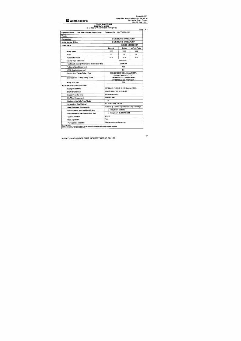
1 泵 息/ Pump Details
订单号
P.O. No.:
R05323-P-001A 设备工位号
Equipment No.
245-PP-008 文件编号
Doc. No.
NJA063
强大合同号
Kingda Contract No.
1036143-0001-05 泵型号
Pump Model
M50KSG-DB/T
2 电机 息/Motor Details
制造者
Make
WEG 电机编号
Serial No.
1010566619 电机工位号
Motor No.
245-PP-008-M1
电机型号
Motor Model
444/5T 电机等级
Motor Rating
55KW 电机转速
Motor Speed
1785
3 试验 息/Test Details
测试开始时间
Pump Started
18:00 测试结束时间
Pump Stopped
19:22 试验日期
Test Date
2011.10.31
轴承温度
Bearing Temp.
50 环境温度
Ambient Temp.
22 水温
Water Temp.
22
4 试验性能参数 证/Performance Test Data Tolerance & Standard
参数名称/Parameter 流量/Flow 扬程/Head 效率/Efficiency 标准依据/Standard: ANSI/HI 1.6-B
5机械运行公差
Mechanical Run Tolerance & Standard
5.1 振动/Vibration 标准依据/Standard: JB/T8097-1999
5.2 噪声级别/Noise Level
参考合同规范 /As per Order Spec.: 最大 85dbA/Max 85
dB(A)
5.3 温升标准/Rise in Temp. Acceptance
标准依据/Standard: JB/T8096-1998
测试后温度 /Measured Temp.

7/17/2019 R05323-P-001A-X009-0042.pdf
http://slidepdf.com/reader/full/r05323-p-001a-x009-0042pdf 56/463
SERIES (M/R) KSH/KSG SLURRY PUMP
INSTALLATION, OPERATION AND MAINTENANCE
MANUAL
SHIJIAZHUANG KINGDA PUMP INDUSTRY GROUP CO.,LTD
2010
7/17/2019 R05323-P-001A-X009-0042.pdf
http://slidepdf.com/reader/full/r05323-p-001a-x009-0042pdf 57/463
Series (M/R) KSH/KSG Slurry PumpInstallation, Operation & Maintenance Manual
Shijiazhuang Kingda Pump Industry Group Co.,Ltd
1
Content
1. General Introduction…………………………….……………………………….…..2
2. Construction…………………………….…………………………………………………3
3. Installation…………………………………………………………………………………..6
4. Operation………………………………………………………………………….……….12
5. Maintenance……………………………………………………………………………….17
6. Possible Failures, Cause and Solutions……………………………….…………..20

7/17/2019 R05323-P-001A-X009-0042.pdf
http://slidepdf.com/reader/full/r05323-p-001a-x009-0042pdf 58/463
Series (M/R) KSH/KSG Slurry PumpInstallation, Operation & Maintenance Manual
Shijiazhuang Kingda Pump Industry Group Co.,Ltd
1 . GENERAL I N TRODUCT I ON
Series (M/R) KSH/KSG Pump is also called “High Efficiency Slurry Pump”. Because these pumps
are fitted with thick wear-resistant parts and heavy frame, so they are suitable to pump the slurry
of highly abrasion, high or low content and high head. During the max permissible working
pressure range, these pumps can be operated in serial. They also can transport the corrosive
slurries.
TYPE DEMONSTRATION:
2
Frame Type/Lubrication Type
Pump Type
Pump Discharge Diameter. (mm)
Metal Lined/Rubber Lined
Example: M200KSH (/KSG)-FA (/B)
M/R M for Metal Liner, R for Rubber Liner
200 Discharge Diameter is 200 mm
KSH Kingda Heavy-duty Slurry Pump
KSG Kingda High-head Slurry Pump
F Frame Type
A/B A for oil lubrication, B for grease lubrication

7/17/2019 R05323-P-001A-X009-0042.pdf
http://slidepdf.com/reader/full/r05323-p-001a-x009-0042pdf 59/463
Series (M/R) KSH/KSG Slurry PumpInstallation, Operation & Maintenance Manual
Shijiazhuang Kingda Pump Industry Group Co.,Ltd
2 . CONSTRUCT I ON
2.1 Pump Head (See Figure 1 and Figure 2)
Both Series (M/R) KSH/KSG metal-lined and rubber-lined pump have construction of
double-casing. They have the replaceable wear-resistant metal liner or rubber liner (including the
impeller, liner, frame plate, etc). Pump casing and cover are made of ductile cast iron; their
construction is vertically split and connected with the bolts. The casing is connected with the
frame with the bolt. When the suction of the pump is installed horizontally, the discharge can be
orientated in any 8 positions at 45° intervals. The front and rear cover plates of impeller have the
back vanes to decrease the leakage and raise the service life of the pumps. Viewing the pump
from the drive side, it should rotate clockwise.
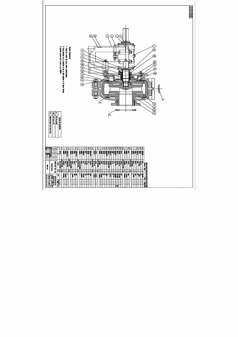
Figure 1 Construction Drawing of MKSH/MKSG (Metal-lined)
Discharge diameter<40mm, open type impeller; Discharge diameter>40mm, enclosed type impeller.
1 Frame 2 Pump Cover 3 Cover Plate 4 Impeller
5 Liner 6 Pump Casing 7 Frame Plate 8 Packing Box
3

7/17/2019 R05323-P-001A-X009-0042.pdf
http://slidepdf.com/reader/full/r05323-p-001a-x009-0042pdf 60/463
Series (M/R) KSH/KSG Slurry PumpInstallation, Operation & Maintenance Manual
Shijiazhuang Kingda Pump Industry Group Co.,Ltd
Figure 2 Construction Drawing of RKSH/RKSG (Rubber-lined)
Discharge diameter<40mm, open type impeller; Discharge diameter>40mm, enclosed type impeller.
1 Frame 2 Pump Cover 3 Cover Plate (R) 4 Impeller
5 Cover Liner 6 Pump Casing 7 Frame Liner 8 Packing Box
2.2 Shaft Seal
There three types of shaft seals, packing seal, expeller seal and mechanical seal.
(1) Packing Seal: simple construction and easy maintenance. Shaft seal water is required. For the
condition which does not need the expeller seal, the packing seal can be used.
(2) Expeller Seal: Expeller seal can be used on the single stage pump or the first stage pump in
serial when the suction positive pressure is not more than the discharge pressure by 10%. The
expeller seal does not require the shaft seal water, and the slurry will not be diluted, which can
reach good sealing effect.
(3) Mechanical Seal: Mechanical seal features for highly wear resistant and shock resistance. It
can get non-leak sealing effect under various bad conditions, and be easily installed and
4

7/17/2019 R05323-P-001A-X009-0042.pdf
http://slidepdf.com/reader/full/r05323-p-001a-x009-0042pdf 61/463
Series (M/R) KSH/KSG Slurry PumpInstallation, Operation & Maintenance Manual
Shijiazhuang Kingda Pump Industry Group Co.,Ltd
5
replaced.
2.3 Transmission Part
During the bearing assembly of (M/R) KSH/KSG Pump, the pump has large diameter, high
stiffness and short cantilever, which will not bend and vibrate under the bad working conditions.
According to the different transmitted power, heavy single-row or double-row tapered roller
bearings can be selected. These bearings can stand the max axial and radial load of the pump. Oil
lubrication is used for the bearing. Seal cover, labyrinth bush, water-proof cover and guard cover
are fitted at the both sides of the bearing body, to prevent the impurities and water from entering
into the bearing and ensure the normal and safe operation of the bearing.

7/17/2019 R05323-P-001A-X009-0042.pdf
http://slidepdf.com/reader/full/r05323-p-001a-x009-0042pdf 62/463
Series (M/R) KSH/KSG Slurry PumpInstallation, Operation & Maintenance Manual
Shijiazhuang Kingda Pump Industry Group Co.,Ltd
3 . I N ST A LL AT I ON
3.1 Installation of Bearing Assembly (See Figure 3 and 4)
Heat the bearing inner ring before assembly, the temperature is not allowed to be over 120 and
the inner ring must contact the shaft shoulder closely. For the double row tapered roller bearing,
the inner ring, the outer ring and position bush is a package, not allowed to exchange with the
respective parts of the like bearings. For frame A, B, C, D, E, F, G, the bearing is single row
tapered roller type; when in assembly, adjust the pad at the bearing end cover to ensure the axial
clearance. The axial clearance should be in accordance with the following table:
Frame A B C D E F、G
Axial Clearance (mm) 0.05-0.15 0.1-0.2 0.15-0.25 0.18-0.28 0.4-0.6 0.5-0.6
For frame R, S, ST, T, TU, U, the bearing at the pump end is double row tapered roller type and
motor end is cylindrical roller bearing, there is no need to adjust the axial clearance for these
bearings.
Proper grease has been filled when assembling the bearing. The seal at the bearing end is
labyrinth ring or bush type; notice the relative arrangement of breach on the diametrical
direction when assembling the labyrinth ring.
Recommend using lithium base grease 2# or 3# and filled quantity as following:
Frame
Lubrication
B C D E F G
R.
RS
S.
ST
T.
TU
Drive End (g) 30 50 100 200 500 1150 200 500 1150
Driven End (g) 30 50 100 200 500 1150 400 1000 2300
6

7/17/2019 R05323-P-001A-X009-0042.pdf
http://slidepdf.com/reader/full/r05323-p-001a-x009-0042pdf 63/463
Series (M/R) KSH/KSG Slurry PumpInstallation, Operation & Maintenance Manual
Shijiazhuang Kingda Pump Industry Group Co.,Ltd
Figure 3 Constructions Drawing of R, S, ST, TU, T, U Frame Bearing Assembly
1 Labyrinth Bush 2 Oil Cup 3 Bearing Body 4 Bearing
5 End Cover 6 End Cover Seal Pad 7 Shaft
Figure 4 Construction Drawing of A,B,C,D,E,F,G Frame Bearing Assembly
1 Labyrinth Bush 2 Oil Cup 3 Grease Blocker 4 Bearing Body
5 Bearing 6 Adjusting Pad 7 End Cover 8 Shaft
3.2 Installation of Shaft Packing Seal
Shaft packing seal assembly includes packing box, shaft sleeve, position bush, seal ring, packing,
packing pad, lantern ring, front lantern ring and packing gland. Packing seal assembly is divided
into lantern ring structure and front lantern ring structure. Front lantern ring structure is the
standard-installed type, and you can see Figure 5 (1) and Figure 5 (2) for the installation drawing.
Lantern ring structure should be used for the condition of suction, for example of installation way
7

7/17/2019 R05323-P-001A-X009-0042.pdf
http://slidepdf.com/reader/full/r05323-p-001a-x009-0042pdf 64/463
Series (M/R) KSH/KSG Slurry PumpInstallation, Operation & Maintenance Manual
Shijiazhuang Kingda Pump Industry Group Co.,Ltd
in Figure 6 (1) and (2). Take notice that the seal ring must be in the right position between shaft
sleeve and position bush, and the shaft sleeve and impeller.
Figure 5 (1) and Figure 6 (1) are the construction drawing for the pump of discharge diameter
less than 150mm;
Figure 5 (2) and Figure 6 (2) are the construction drawing for the pump of discharge diameter
more than 500mm.
Selection of the packing: when the working pressure of the pump is below 1MPa (10kgf/cm2),
asbestos fibers dip mica packing is usually used; asbestos fibers soaked PTFE packing is usually
used when the pressure is higher than 1MPa (10kgf/cm2) or pumping the corrosive slurry.
Figure 5(1) Packing Seal Construction
Standard Type
Figure 6(1) Packing Seal Construction
For Suction-Up Condition
1 Shaft Sleeve 2 Packing 1 Shaft Sleeve 2 Packing
3 Packing Box 4 Front Lantern Ring 3 Packing Box 4 Lantern Ring
5 Seal Ring 6 Locating Bush 5 Seal Ring 6 Locating Bush
7 Packing Pad
8

7/17/2019 R05323-P-001A-X009-0042.pdf
http://slidepdf.com/reader/full/r05323-p-001a-x009-0042pdf 65/463
Series (M/R) KSH/KSG Slurry PumpInstallation, Operation & Maintenance Manual
Shijiazhuang Kingda Pump Industry Group Co.,Ltd
9
Figure 5(2) Packing Seal Construction
Standard Type
Figure 6(2) Packing Seal Construction
For Suction-Up Condition
1 Shaft Sleeve 2 Packing 1 Shaft Sleeve 2 Packing
3 Packing Box 4 Front Lantern Ring 3 Packing Box 4 Lantern Ring
5 Packing Pad
3.3 Installation of Expeller Seal
Expeller seal assembly includes expeller, release cover shaft sleeve, lantern ring, packing pad,
packing, packing gland, etc. Every part must be installed at right position as in Figure 7.
Figure 7 Seal Construction of Expeller
1 Packing Gland 2 Release Cover 3 Expeller 4 Shaft Sleeve

7/17/2019 R05323-P-001A-X009-0042.pdf
http://slidepdf.com/reader/full/r05323-p-001a-x009-0042pdf 66/463
Series (M/R) KSH/KSG Slurry PumpInstallation, Operation & Maintenance Manual
Shijiazhuang Kingda Pump Industry Group Co.,Ltd
5 Seal Ring 6 Packing 7 Lantern Ring 8 Packing Pad
3.4 Installation of Mechanical Seal
Mechanical seal assembly includes Cartridge type mechanical seal, seal box, seal ring, etc.
Strictly install the mechanical seal according to the Manual. See Figure 8 for construction.
Figure 8 Construction of Mechanical Seal
1 Seal Box 2 Seal Ring 3 Mechanical Seal
3.5 Installation of Pump Head
Firstly fit the pump body on the frame, then put the shaft seal assembly into the pump body; fit
the rear guard plate and impeller with rear hanging pipe and rear set nut; fit the liner with the
hanging beam and use the bolts to press the liner against the pump body; fit the front guard the
plate into the pump cover, bolt the pump cover, front plate together with the pump body and
fasten all the bolts and nuts. For rubber liner pump, the front liner should be firstly put into the
pump cover and fasten the bolts, then assembly the pump body and pump cover; coat the soapy
water and rubber lubricant at the contact surface for the easy assembly; take notice that the seal
pads should be put at the right position and compressed; to assure the correct position and easy
assembly, the rear guard plate and rear liner hang pipe *302, rear guard plate and rear liner
position nut *302 and liner hanging beam *304 can be used. Following Figures show the
10

7/17/2019 R05323-P-001A-X009-0042.pdf
http://slidepdf.com/reader/full/r05323-p-001a-x009-0042pdf 67/463
Series (M/R) KSH/KSG Slurry PumpInstallation, Operation & Maintenance Manual
Shijiazhuang Kingda Pump Industry Group Co.,Ltd
methods.
The pump with ST, T and TU has release ring; before dismantling, the three hex bolts should be
removed and screw them into thither bolt hole on the release ring to jack the three pressure pad
on the shaft to loose the impeller.
Figure 9
1. Rear Guard Plate and Rear Liner Hang Pipe x302
2. Rear Guard Plate and Rear Liner Setting Nut x303
3. Liner Hang Beam x304
11

7/17/2019 R05323-P-001A-X009-0042.pdf
http://slidepdf.com/reader/full/r05323-p-001a-x009-0042pdf 68/463
Series (M/R) KSH/KSG Slurry PumpInstallation, Operation & Maintenance Manual
Shijiazhuang Kingda Pump Industry Group Co.,Ltd
12
4 . OPERAT I ON
4.1 Startup
Check the whole machine unit as following procedure before start up:
(1): The pump should be installed on the solid base to bear the whole pump weight to absorb the
vibration and fasten all the foundation bolts.
(2): The pipeline and valves should be separately supported. There is seal pad at the pump flange.
Notice that the pump metal liner may be higher than flange surface when fastening the bolts, and
the bolts should be not over-fastened to avoid damaging the seal pad.
(3): Rotate the pump shaft in accordance with the pump rotation direction, the shaft should drive
the impeller without the friction; if not, the impeller clearance should be adjusted.
(4): Check the motor rotation direction to make sure it can drive the pump rotate toward the
arrow. Reverse rotation may cause the impeller screw stripped and damage the pump, so it’s
forbidden.
(5): For direct coupling drive, the pump shaft and motor shaft should be strictly centered. The
pump shaft and motor shaft should be in parallel for the belt transmission and adjust the pulley
position to make it vertical to the belt. For the pulley unit of SPA Type andSPA
SPB Type, SPB Type
andSPB
SPC Type, the adjustment of the pulley should reach the requirements of α1=α2 in Figure 10.
(6): A short removable pipe should be fit at the suction of the pump, its length is enough to
disassemble the pump cover, replace the wearing parts and inspect the pump. See the Outline
Dimensional Drawing for the length of this short pipe.
(7): Check shaft seal: for the pumps of expeller seal, when the oil cup is fit with the release gland,
the lubricating grease should be filled through the oil cup; and Sodium-calcium grease is

7/17/2019 R05323-P-001A-X009-0042.pdf
http://slidepdf.com/reader/full/r05323-p-001a-x009-0042pdf 69/463
Series (M/R) KSH/KSG Slurry PumpInstallation, Operation & Maintenance Manual
Shijiazhuang Kingda Pump Industry Group Co.,Ltd
recommended.
For the pumps of packing seal, firstly turn on the shaft sealing water system to check if the water
quantity and pressure is proper before the startup of the pump; adjust the packing gland set
screw to regulate the tension of the packing; adjust shaft seal water (that the leak quantity at the
packing gland is drop by drop); if too tight, the shaft sleeve will heat easily and power will be
consumed more; if too loose, the leak quantity will be very large. The shaft seal water pressure
usually is higher than pump discharge pressure by 3.5X10⁻²MPa (0.35kgf/cm2). See following
table for shaft seal water quantity:
Frame Type A B C D E.F G R.RS S.ST T.TU U
Shaft Seal Water Quantity (L/s) 0.15 0.25 0.35 0.55 0.70 1.2 0.70 1.2 1.6 2.1
(8) Adjustment for the Belt Pretightening Force
We recommend following method for reference:
(8.1) First calculate thee pretightening force Q:
Q=2
1
21 )5.2(510mv
V Z C
C PC +
××
×− (Newton)
(8.2) Then find the e value on the curve according to the pretightening force and belt type;
(8.3) Find f through formula f=e
.
L’
100 ;
(8.4) Find R value of respective V-belt in Table 1, and adjust the center distance of both pulleys
according to the methods in Figure 11 to reach the required pretightening force. Usually, if the
overall reduction is no more than f when loading the Newton force, it reaches the required
pretightening force Q.
In the formula:
Q: the minimum pretightening force of each belt in the static state, unit is Newton;
13
7/17/2019 R05323-P-001A-X009-0042.pdf
http://slidepdf.com/reader/full/r05323-p-001a-x009-0042pdf 70/463
Series (M/R) KSH/KSG Slurry PumpInstallation, Operation & Maintenance Manual
Shijiazhuang Kingda Pump Industry Group Co.,Ltd
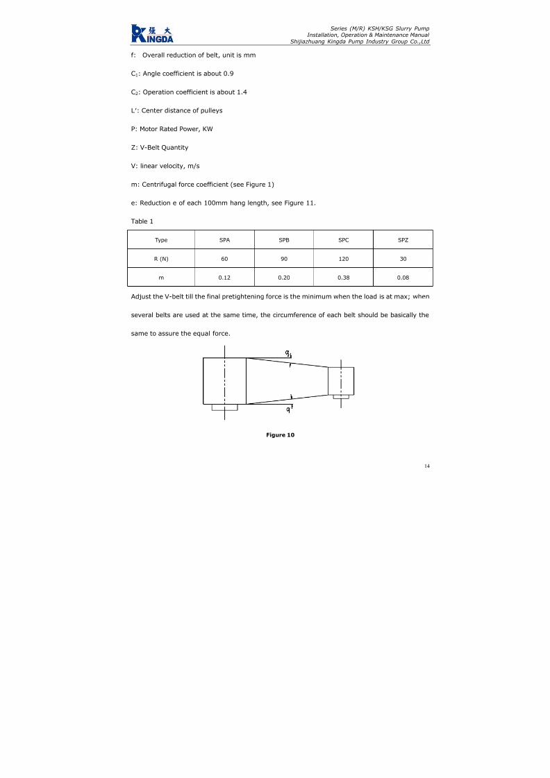
f: Overall reduction of belt, unit is mm
C1: Angle coefficient is about 0.9
C2: Operation coefficient is about 1.4
L′: Center distance of pulleys
P: Motor Rated Power, KW
Z: V-Belt Quantity
V: linear velocity, m/s
m: Centrifugal force coefficient (see Figure 1)
e: Reduction e of each 100mm hang length, see Figure 11.
Table 1
Type SPA SPB SPC SPZ
R (N) 60 90 120 30
m 0.12 0.20 0.38 0.08
Adjust the V-belt till the final pretightening force is the minimum when the load is at max; when
several belts are used at the same time, the circumference of each belt should be basically the
same to assure the equal force.
Figure 10
14

7/17/2019 R05323-P-001A-X009-0042.pdf
http://slidepdf.com/reader/full/r05323-p-001a-x009-0042pdf 71/463
Series (M/R) KSH/KSG Slurry PumpInstallation, Operation & Maintenance Manual
Shijiazhuang Kingda Pump Industry Group Co.,Ltd
Figure 11
After adjustment of the V-belt, check if the impeller can rotate normally again; if possible, start
the pump with clear water (before it begins to pump the slurry); turn on the suction pipe valve,
start the motor, check the pressure and flow quantity at the suction and discharge, check the
leakage at the packing. If the packing heats, loose the packing gland bolts to make the leakage
bigger; adjust the leakage to the specified value till the packing run-in with the shaft.
4.2 Operation
(1): Periodically check the pressure and flow quantity of shaft seal water, and adjust the packing
gland and replace the packing during the operation to assure small quantity of clean water
passing through the shaft.
15

7/17/2019 R05323-P-001A-X009-0042.pdf
http://slidepdf.com/reader/full/r05323-p-001a-x009-0042pdf 72/463
Series (M/R) KSH/KSG Slurry PumpInstallation, Operation & Maintenance Manual
Shijiazhuang Kingda Pump Industry Group Co.,Ltd
16
(2): Periodically check the frame. If the bearing heats at the beginning of the operation, shut
down the pump till the bearing become cool, then run it. If the bearing heats seriously and
temperature keep rising, the frame must be disassembled and examined for the cause. Usually
the impurity contained in the lubricating oil can cause the heating, so the bearing oil should be
proper and clean, and replaced periodically.
(3): The pump performance will become poorer and the efficiency will become lower with the
larger and larger clearance between impeller and front guard plate. So adjust the impeller timely
to keep the proper clearance to make the pump run in high efficiency. When the wear situation of
the pump is too bad to meet the requirements of the system, the wear parts should be replaced.
4.3 Shutdown of Pump
Let the pump to transport the clear water for some before the shutdown to clean the slurry left
inside the pump, then stop the pump, valve, packing seal water or mechanical seal water in order.

7/17/2019 R05323-P-001A-X009-0042.pdf
http://slidepdf.com/reader/full/r05323-p-001a-x009-0042pdf 73/463
Series (M/R) KSH/KSG Slurry PumpInstallation, Operation & Maintenance Manual
Shijiazhuang Kingda Pump Industry Group Co.,Ltd
17
5 . MA I NTENAN CE
For the safe run of pump, attention must be paid to the normal maintenance as following aspects:
5.1 Maintenance of shaft seal:
For the packing seal pump, periodically check the water pressure and water quantity of shaft
packing seal. Always keep small quantity of clear water flow along with the shaft, periodically
adjust the packing gland, check and replace the packing. The shaft seal water pressure and
quantity should in accordance with the above requirements. Periodically fill the oil into the oil cup
for the expeller seal pump to lubricate the inside packing.
5.2 Adjustment of impeller:
To assure the high-efficiency of the pump, the clearance between the impeller and the front guard
plate; the clearance between impeller and front guard plate of metal liner pump should be
0.5-1mm, the clearance between the impeller and front liner should be equal to that between
impeller and rear liner.
Before adjusting the clearance, the pump should be stopped firstly, then loose the bolts of
bearing assembly and screw the nut of adjusting bolts to make the bearing assembly move
forward, at the same time, rotate the pump as per the arrow by hands till the impeller friction
with the front guard plate; for the metal liner pump, loose the nut (which was fastened) by half
circle, then fasten the nut on the adjusting bolt to make the bearing assembly move backward,
the clearance between the impeller and front guard plate should be 0.5-1mm; for the rubber liner
pump, adjust the nut of the adjusting bolts to make the bearing assembly to move forward to
contact with the front guard sleeve, then move the bearing assembly back to contact with the
back liner, and measure the total movement distance, make the half of this distance as the

7/17/2019 R05323-P-001A-X009-0042.pdf
http://slidepdf.com/reader/full/r05323-p-001a-x009-0042pdf 74/463
Series (M/R) KSH/KSG Slurry PumpInstallation, Operation & Maintenance Manual
Shijiazhuang Kingda Pump Industry Group Co.,Ltd
18
clearance of the impeller and front liner; assure the correct clearance of impeller and front and
back liner by adjusting bearing assembly position through the adjusting bolts.
After the adjustment, check if the impeller can rotate normally before startup, if bearing
assembly compress bolts and adjusting bolts are tightened; then start the pump.
5.3 Lubricating of Bearing
Correct assembly, proper lubricating and in-time maintenance will make the service life of
bearing assembly longer. Periodically check the bearing assembly, bearing and lubricant and
interval should not be over than 12 month. Fill the lubricating grease at regular intervals in
operation, the filling interval and filling quantity are relative to the pump speed, bearing size,
continuous operation time, shutdown and startup times, environmental condition and
temperatures; excess grease will cause the heating of bearing. Refer to following table for proper
lubricating schedule:
5.4 Standby pump should be rotated by 1/4 circle by hands to make the bearing stand static load
and vibration evenly

7/17/2019 R05323-P-001A-X009-0042.pdf
http://slidepdf.com/reader/full/r05323-p-001a-x009-0042pdf 75/463
Series (M/R) KSH/KSG Slurry PumpInstallation, Operation & Maintenance Manual
Shijiazhuang Kingda Pump Industry Group Co.,Ltd
Lubrication Schedule (in hours)
19
Note: Above Schedule is only applied for the normal working condition.
During the bearing assembly, the internal plug is to fill the bearing grease, and the external oil
cup is to clean the labyrinth seal. Besides the regular filling of grease, it’s also to fill the grease to
the oil cup to keep the labyrinth seal clean.
Bearing Speed (rpm)Frame
Type
Grease
Quantity 200 300 400 600 800 1000 1200 1800 2000
B 12 3000 2400 1800 1500 1000
C 18 3600 2400 1800 1600 1200 900
D 28 2500 2000 1500 1200 800 500
E 44 5000 3600 2200 1600 1100 800 500
F 71 7000 4200 2000 1800 1200 700 400
R.RS 102 3000 2000 1400 1000 600 400 100
S.ST 132 3800 28000 1500 900 500 300
T.TU 304 4800 3000 1800 900 400
Pump
End
U 621 4000 2400 1500 500
R.RS 61 8000 4800 3500 2800 2200 1500 900
S.ST 74 8000 6000 3600 2400 1600 1200
T.TU 133 8000 7000 4500 2500 1500
Motor
End
U 192 7000 6000 4000 2000

7/17/2019 R05323-P-001A-X009-0042.pdf
http://slidepdf.com/reader/full/r05323-p-001a-x009-0042pdf 76/463
Series (M/R) KSH/KSG Slurry PumpInstallation, Operation & Maintenance Manual
Shijiazhuang Kingda Pump Industry Group Co.,Ltd
20
6 . POSS I B LE FA I LURES , CAUSE AN D SOLUT I ONS
Failure Cause Solutions
Leak at the suction pipe or packing Block the leak
Wrong rotation direction Change the rotation direction
Impeller is broken Replace the new impeller
Not pump the liquid
Suction pipe is blocked Remove the block
Packing gland is to tight and packing heats Loose the packing gland bolts
Friction inside the pump Adjust the clearance
Bearing is broken Replace the bearing
Transmission belt is too tight Adjust the belt
Too large flow quantity Adjust the pump running conditions
High rotation speed, large proportion Adjust the rotation and proportion
Shaft Power is to high
Misalignment or nonparallel of motor shaft and Adjust the motor shaft and pump shaft
Excessive or too little of bearing lubricating oil Oil quantity should be as per
Impurities is contained in the lubricating oil Replace the new lubricating oilOverheat of bearing
Bearing is broken Replace the new bearing
Misalignment or nonparallel of motor shaft and Adjust the motor shaft and pump shaft
Shaft is bent Replace a new shaft
Friction inside the pump or the imbalance of Decrease the friction and replace a new
Foreign matter inside the bearing Clean the bearing
Service life of bearing is short
Unreasonable assembly of bearing Replace the bearing or reassemble the
Serious abrasion of packing Replace the new packing
Serious abrasion of shaft sleeve Replace the new shaft sleeveSerious leakage at the packing
Seal water is not clean Replace the clean seal water
Bearing is broken Change new bearing
Impeller is not in balance Change new impeller
Air entered into suction pipe, block Remove the air and block
Uneven flow, pump empty Improve the feeding condition
Abnormal noise and excessive vibration
of pump
Bad foundation Strength the foundation

7/17/2019 R05323-P-001A-X009-0042.pdf
http://slidepdf.com/reader/full/r05323-p-001a-x009-0042pdf 77/463
INSTALLATION,OPERATION ANDMAINTENANCE
INSTRUCTION MANUALFOR INDUCTION
MOTORSFrame sizes 143/5T to 586/7
WEG EXPORTADORA S.A.
Av. Prefeito Waldemar Grubba, 300089256-900 - J aragua do Sul - SC - BRAZIL
Phone 55 (47) 3372-4000 - Fax 55 (47) 3372-4060http://www.weg.com.br
Transforming Energy into Solutions
0 2 8 0 . 1
5 1 5 / 0 3 . 2
0 0 6

7/17/2019 R05323-P-001A-X009-0042.pdf
http://slidepdf.com/reader/full/r05323-p-001a-x009-0042pdf 78/463
THIS MANUAL IS INTENDED TO SUPPLY IMPORTANT TOPICS THAT MUST BE FOLLOWED DURING
TRANSPORTATION, INSTALLATION, OPERATION AND MAINTENANCE OF WEG MOTORS. THEREFORE, WE RECOMMEND READING CAREFULLY THIS MANUALBEFORE INSTALLING AND OPERATING THE MOTOR.
TO ENSURE PHYSICAL INTEGRITY TO THE OPERATION AND MATERIAL PROTECTION, ALL
INFORMATION INCLUDED IN THIS MANUAL MUST BE STRICTLY FOLLOWED.
I
INDEX
1. HANDLI NG AND TRANSPORTATION 2. RECEIVING INSPECTION 3. STORAGE 4. INSTALLATION
4.1 - Safe ty 4.2 - Op e ra ti ng Co n di ti o ns 4.3 - Fo u nd a ti on 4.4 - D ra in H o le s 4.5 - B alan ce 4.6 - Al ig nm e nt 4.7 - C ou p li ng s 4.8 - El ec t r ic a l Co n ne c t io n 4.9 - St ar ti ng Me th o ds 4 .10 - P ro tec t i on Dev i ce
4.11 - Star t -Up 5. MAINTENANCE
5.1 - Lubrication 5.1 .1 - Mach ines wi thout Grease Nipp les 5.1.2 - Mac hines Fitted with G rease Fitting 5.1.3 - Com patibil ity of MOBIL Polirex EM
grease with other types of grease 5 .2 - A ssemb ly and D i s as semb l y
6. SPARE PARTS 7. VARIABLE FREQUENCY DRIVE MOTORS
7.1 - St an d ar d Mo t or s 7 .2 - I nv er te r Du t y Mo to r s 7 .3 - Bear in g I n su l at io n
8. ADDITIONAL INSTRUCTIONS 8 .1 - Haza rd ou s Ar ea Mo to r s
8.1 .1 - Gene ra l 8.1.2 - Instal lat ion 8.1 .3 - Chec k ing and main tenanc e 8.1.4 - Explosion Proof M otor Repairs
9. WARRANTY TERMS
Purchasing date:
Supplier’s name
Invoice/Order number:
Customer’s name and phone:
Failure description:

7/17/2019 R05323-P-001A-X009-0042.pdf
http://slidepdf.com/reader/full/r05323-p-001a-x009-0042pdf 79/463
Lifting devices, when supplied, are designed only to supportthe motor. If the motor has two lifting devices then a double chainmust be used to lift it.Lifting and lowering must be done gently without any shocks, toavoid bearing damaged.
DURING TRANSPORTATION, MOTORS FITTED WITH ROLLER OR ANGULAR CONTACT
BEARINGS ARE PROTECTED AGAINST BEARING DAMAGES WITH A SHAFT LOCKING DEVICE
MOTORS MUST NOT BE LIFTED BY THE SHAFT,
BUT BY THE EYEBOLTS SPECIFIC FOR SUCH
PURPOSE
THIS LOCKING DEVICE MUST BE USED ON ANY FURTHER MOTOR TRANSPORTATION, EVEN
WHEN THIS MEANS TO UNCOUPLE THE MOTOR FROM THE DRIVEN MACHINE
I
I
I
2. RECEIVING INSPECTION
When receiving the motor, check if any damage has occurredduring transportation.
If anything has been noticed, notify immediately the carrier, theinsurance company and WEG.Failure in giving notice to the carrier, to the insurance companyand to WEG may result in loosing product warranty.
Do not remove the existing protecting grease from the shaft end,nor the stoppers or plugs that close the terminal box holes, if any.
These protection items must be kept in place until the finalinstallation has been concluded.After being removed from the package, a complete visualinspection on the motor should be made:
1 - HANDLING AND TRANSPORTATIONFecha de compra:
Nombre del proveedor:
Número de la factura o pedido:
Nombre y número telefónico del cliente:
Descripción de la falla:

7/17/2019 R05323-P-001A-X009-0042.pdf
http://slidepdf.com/reader/full/r05323-p-001a-x009-0042pdf 80/463
If motors are not immediately installed, they must be stored indry areas, free of dust, vibrations, gases, corrosive smokes, underconstant temperature and in normal position free from othermaterials.
Motor storage temperature must remain between 41ºF (5ºC) to140ºF (60ºC), with relative humidity not exceeding 50%.
If motors are stored for more than two years, bearings must bereplaced or the lubrication grease must be totally removed aftercleaning.
Single-phase motors when kept in stock for 2 years or moremust have their capacitors replaced (if any).
WEG recommends to rotate the shaft (by hands) at least once a
month, and to measure the insulation resistance before installingit, if motors are stored for more than 6 months or when subjectto high humidity areas.
If motor is fitted with space heaters, it is recommended to switchthem on during storage period if the relative humidity exceeds50%.If motor remains in stock for a long period without having thespace heaters switched-on or when installed but not in operation,moisture/water inside the motor may condense. On these cases,water must be drained by removing the threaded drain plugs.When drainage is done, switch-on the space heaters and makesure the motor is completely dry, then reinstall the drain plugs toensure proper Degree of Protection (see figure 1).
The space heaters should NEVER be energized while motor isrunning.
3 - STORAGE
ü Check if any damage has occured during transportation.ü Check nameplate data.ü Rotate shaft with the hand to make sure it is running freely.ü Make sure the motor was not exposed to excessive dirt andmoisture during transportation and storage.
9. TERMINOS DE GARANTIA
WEG of rec e garantía co nt ra defec tos d e fabr icac ión o d e materiales para sus p roduc tos, por un p eríodo de 18 me ses,con tados a partir de la fecha de la emisión de la factura por parte de fáb rica o d el distribuidor/revendedor, teniendo c omo límite 24 meses d e la fecha de fabric ación indep endiente de la fecha de instalac ión del motor, siemp re y cuand o hayan sido sat isfechos los siguientes requis i tos:
- Transpor te , manoseo y a lmacenamiento adecuados; - I n s t a la c i ón co r r e c t a y en cond i c i o ne s amb i e n t a l e s espec íficas y sin presenc ia de g a ses corrosivos; - Operación dentro de los límites de la capacid ad del moto r; - Realización periódica del d ebido m antenimiento prevent ivo; - Realización de reparaciones y/o modif icaciones al producto original efectuada solo por los agentes autorizados de la Red de Asiste nc ia Técn ic a WEG; - Entregar el producto a l proveedor en el caso de ocurr i r una fal la c on rec lam aci ón d e g arant ía en un p eríod o m ínim o su f i c i en te p a ra iden t i f i ca r la causa d e la an oma lía y su conven ien te repa rac ión ; - Dar av iso inmed ia to a WEG, por par te de l c l ien te , de los defectos detec tados y que los mismos sean poster iormente ana l i za do s po r WEG co mo c au sado s po r de f e c t o s de fabr icac ión.La garant ía no inc luye los servicios de desmo ntaje d el moto r en las ins ta lac iones de l c l ien te , cos to s de t ranspor te de l produc to y gastos de traslado, alojamiento y alimentación del person al de Asistencia Técnic a cuand o sean solic itados p or e l c l ien te .Los ser vicio s en ga rantía serán pre stad os exc lusivam ente e n talleres d e Asistenc ia Técn ica Aut orizada WEG o en la prop ia fábric a.Se excluyen de esta gara ntía los c ompon entes c uya vida útil,en u so no rmal, sea inferior a l períod o d e ga rantía ot orga do po r WEG las repa rac ion es o subs t i t u c iones de p iezas o pro duc t os , a cr i te r io de WEG o su Asis ten c ia Técn ica Autori zada, no pro rrog ará el plazo de g arantía orig inal.La presente g arantía se limita al pro duc to entreg ado, no sien do respon sable WEG po r daños a person as, a terc eros, a o tros
equipos e instalaciones, ut i l idades que se dejen de ob tener o cu alquier otro daño eme rgente o c onsec uente.

7/17/2019 R05323-P-001A-X009-0042.pdf
http://slidepdf.com/reader/full/r05323-p-001a-x009-0042pdf 81/463
Insulation Resistance Checking
Disconnect motor from power supply before making anyinsulation resistance measurement.
To avoid electric discharge risks, discharge the terminals rightafter performing the measurement.
Measure the insulation resistance before operating the motorand/or when there is any sign of moisture in the winding.
The resistance measured at 77ºF (25ºC) must be:
Ri ≥
(20 x U) / (1000 + 2P) [MΩ](measured with a MEGGER at 500 V d.c.)where U = voltage (V); P = power (kW).
If the insulation resistance detected is less than 2 mega ohms, thewinding must be dried according to the following procedure:Warm it up in an oven at a minimum temperature of 176ºF (80ºC)increasing 41ºF (5ºC) every hour until reaching 105ºC (221ºF),remaining under this temperature for at least one hour.
Figure 1
P Las superficies de encaje de los motores a prueba de explosiónno deben ser mecanizadas y no es permitido utilizar entre ellasningún tipo de vedamiento, no descrito o suministrado por elfabricante. Los encajes deben ser solamente limpios y para evitarcorrosión o penetración de agua, los encajes pueden serengrasados con una fina manta de grasa de silicona.P Verificar si los componentes están exentos de rebabas, golpesy suciedad.P Observar si las piezas están en perfectas condiciones.P Lubricar superficialmente las guías de las tapas con aceiteprotector para facilitar el montaje.P Utilizar solamente martillo de material blando en la colocaciónde las piezas.P Verificar si todos los tornillos están bien apretados.P Utilizar sonda calibrada para verificar asiento de la caja deconexiones (menor de 0,05mm).
8.1.4 Reparos De Motores A Prueba De Explosión
El reparo de repuestos, directamente involucrados en laprotección contra riesgo de una explosión, debe ser realizadosin cualquier modificación al diseño original del motor.
Después del reparo, estos repuestos deben ser chequeados ycuando concluido, el taller de asistencia técnica debe hacer unadeclaración de todas las operaciones realizadas en el motorespecífico.
Para maiores informaciones, en México favor comunicarse a:
WEG México, S.A de C.V.Carretera J orobas-Tula Km 3.5,Mz.5, Lote 1, entre Lote 4 y 5
Fracc. Parque Indistrial Huehuetoca,Huehuetoca Estado de Méx., C.P 54680 Tel: (55) 5321-4243 y 61; Fax: (55) 5321-4262 y 94
e-mail: [email protected]

7/17/2019 R05323-P-001A-X009-0042.pdf
http://slidepdf.com/reader/full/r05323-p-001a-x009-0042pdf 82/463
Check if the stator insulation resistance remains constant withinaccepted values. If not, stator must be reimpregnated. If necessary,replace bearings and seals.
Note:
1) All drains (if any) must be removed while drying.2 - Measured the insulation resistance in ambient temperature. If different than 25ºC it should be corrected using the followingformula:
R(25°C) = [( K+25 ) / ( K + Ta )] . R (Ta)
Where:R
(25°C)insulation resistance related to 25ºC ambient temperature
K constant value 234.5 for copper T
aambient temperature where the resistance was measured
R(Ta)
resistance value measured in ambient temperature Ta
4. INSTALLATION
4.1 - Safety
All personnel involved with electrical installations, eitherhandling, lifting, operation, start up, maintenance or repair must
be well informed and updated concerning safety standards andprinciples that govern the work and carefully follow them.
For practical reasons, it is not possible to include in this Manualdetailed information that covers all constructive variables, norcovering all possible assembly, operation or maintenancealternatives.For this reason, the present Manual only includes requiredinformation that allows qualified and trained personnel to carryout the work.
If you still have further doubts about this, specially in referenceto specific product information, WEG is willing to provide suchinformation via its network of authorized service agents and/ordistributors.
In order to allow WEG to provide prompt service, within technicalstandards, the motor serial number that is available on theidentification nameplate should be supplied.
Use always appropriate tools for installation and removal.
LA INSTALACION DE MOTORES PARA AMBIENTES PELIGROSOS DEBE SER EJECUTADA POR
PERSONAL ESPECIALIZADO
LA ESPECIFICACION DEL LOCAL DE INSTALACION ES DE RESPONSABILIDAD DELCLIENTE, QUE TAMBIEN DETERMINARA LAS
CARACTERISTICAS AMBIENTALES
Cuando se utiliza el prensa cables en la entrada de los cables, lomismo debe ser apropiado para el motor y para el tipo de terminal,el prensa cables debe ser montado, completamente apretado demanera a adquirir la presión necesaria arriba de los anillos devedamiento, bien como:ü Evitar la transmisión de vibraciones mecánicas para losterminales del motor.ü Garantizar la protección mecánica “IP” para la caja deconexiones.
8.1.3 Chequeo y Mantenimiento
El mantenimiento debe ser ejecutado por talleres técnicosautorizados y acreditados por WEG.
Talleres y personal sin autorización que realicen reparación enlos motores para ambientes peligrosos, serán totalmenteresponsables por el trabajo ejecutado y los daños ocurridos ensu servicio.
En la ejecución del mantenimiento, instalación y relubricación, sedeben seguir las siguientes orientaciones:
ü Las conexiones deben estar correctamente cerradas para evitarelevación de resistencia, consecuentemente sobrecalentamientodel contactoü Aislamiento distancia-aire y distancia-superficie entre losconductores, requeridos por las normas, deben ser respectados
ü
Todos tornillos utilizados en el montaje de las partes del motory caja de conexión, deben ser completamente apretadosü Vedamientos y repuestos para entrada de los cables seránhechos utilizando materiales suministrados por el fabricante, demanera a garantizar el tipo de protección original
I
I

7/17/2019 R05323-P-001A-X009-0042.pdf
http://slidepdf.com/reader/full/r05323-p-001a-x009-0042pdf 83/463
MAKE SURE THAT ELECTRIC MOTORS ARE SWITCHED OFF BEFORE STARTING ANY MAINTENANCE SERVICE I
All rotating parts such as pulleys, couplings, outside fans, shaft,etc. must be protected against accidental contact.Motors must be protected against unexpected starts.When performing any maintenance service, disconnect the motorfrom the power supply. Make sure all accessories have been
switched off and disconnected.In order to prevent from penetrating dust and/or water into theterminal box, cable glands or threaded pipe in the lead holespassage must be installed. They must be of equal or higher IPrating than the motor.
LEAD CONNECTION INSULATION INSIDE THE TERMINAL BO X MUST BE DONE WITH AN INSULATING
MATERIAL COMPATIBLE WITH MOTOR THERMALCLASS WHICH IS SHOWN ON THE MOTOR
NAMEPLATE
I
If installation and safety instructions are not followed accordingly,warranty may be void.
4.2 - Operating Conditions
In general electric motors are designed for operation up to analtitude of 1000m above sea level for an ambient temperatureranging from -4ºF (-20ºC) to 104ºF (40ºC). Any variation is statedon the nameplate.
The recommended installation distance between air inlet fromthe motor and the wall should be at least ¼ of the air inlet diameter.A person should have enough room to carry out cleaning services.Machines that are cooled with ambient air, air inlet screens mustbe cleaned at regular intervals so as to ensure free air circulation.Warm air can not return to the motor.ü For vertically mounted motors with air inlet on top, the air
opening must be protected by a proper cover so as to avoiddropping of foreign materials on the motors.ü Considering that direct sun heat causes increase intemperature, externally installed motors should be alwaysprotected against weathering.
7.3– Aislamiento del rodamiento
Los motores Inverter Duty en las carcasas 504/5T y 586/7T* sonsuministrados con sistema de puesta a tierra entre el eje y la carcasaen el lado delantero. También, bajo pedido puede ser suministradocon rodamientos aislados.
Para otras líneas, en las carcasas 504/5T y 586/7T* cuando usadoscon convertidor de frecuencia es necesario sistema de puesta atierra entre el eje y la carcasa o rodamientos aislados.
* Otros tamaños de carcasas, bajo consulta.
8 – INSTRUCCIONES ADICIONALES
8.1 – Motores Para Areas de Riesgo
8.1.1 General
Además de las recomendaciones arriba, las siguientes tambiéndeben ser observadas:
Motores para áreas de riesgo son fabricados de acuerdo connormas específicas para estos ambientes.Motores suministrados para áreas de riesgo (áreas clasificadas)deben ser instalados en área que estén de acuerdo con lasespecificadas en la tarjeta de identificación del motor.
Notas:
ü Motores División I son también adecuados para la División IIü Motores de una especificada clase de temperatura son tambiénadecuados para ambientes con combustible de una clase detemperatura mayor (ejemplo, motores T4 son adecuados paraambientes de clase T3, T2, T1).
8.1.2 Instalación
La instalación debe seguir procedimientos elaborados por lalegislación local vigente.

7/17/2019 R05323-P-001A-X009-0042.pdf
http://slidepdf.com/reader/full/r05323-p-001a-x009-0042pdf 84/463
COMPARE THE CURRENT, VOLTAGE, FREQUENCY,SPEED, OUTPUT AND OTHER VALUES REQUIRED BY
THE APPLIC ATION WITH MOTOR NAMEPLATE INFORMATION
I
ODP MOTORS – Open motors (IP21, IP23) are machines designedfor operation in clean, dry areas, with enough air circulation forproper cooling. These motors should never be used in areas withflammable materials. Open motors may cause sparks and releasecast particles under any eventual insulation failure (short-circuit).
TEFC MOTORS – Totally enclosed motors are machines suitable tooperate in areas with moisture, dirt and/or corrosive materials eitherin enclosed or open environments.
4.3 - Foundation
Motors provided with feet must be installed on solid foundationsto avoid excessive vibrations.All motors must be fully fixed and aligned.
The purchaser is fully responsible for the foundation.Metal parts must be painted to avoid corrosion.
The foundation must be uniform and sufficiently strong to supportany shock. It must be designed in such a way to stop any vibration
originated from resonance.
Note: Considering that rotation direction is important for correctoperation, then check it carefully before connecting motor to theload.
4.4 - Drain Holes
Make sure drains are placed at the lower motor position when themounting configuration differs from that specified on the motorpurchase order.
4.5 – Balance
WHEN SPECIAL BALANCE IS REQUIRED,CONTACT THE FACTORY I
EL NO CUMPLIM IENTO DE ESTAS RECOMENDACIONES Y CRITERIOS CAUSA LA
PERDIDA DE GARANTIA DEL MOTOR
7.2 – Motores Inverter Duty
Motores con tensiones superiores a 575V e igual o menor que690V y alimentados por convertidor de frecuencia no necesitanfiltros caso sigan las especificaciones abajo:
I
( * ) I n f o r m a
d o p o r e
l f a b r i c a n
t e d e
l c o n v e r t i d o r .
ü Observar tensión dealimentación del conjuntoventilación forzada.
EL NO CUMPLIMIENTO DE ESTAS
RECOMENDACIONES Y CRITERIOS CAUSA LAPERDIDA DE GARANTIA
DEL MOTOR
I

7/17/2019 R05323-P-001A-X009-0042.pdf
http://slidepdf.com/reader/full/r05323-p-001a-x009-0042pdf 85/463
All motors are dynamically balanced at the factory with half key.
Transmission elements such as pulleys, couplings etc must bedynamically balanced with half key before installation.
Always use appropriate tools for installation and removal.
4.6 – Alignment
ALIGN THE SHAFT ENDS AND USE FLEXIBLE COUPLING, WHENEVER POSSIBLE I
Make sure that the motor mounting devices do not allowmodifications on the alignment and further damages to thebearings.When assembling a half-coupling, make sure to use suitableequipment and tools to protect the bearings.Suitable assembly of half-coupling:Specially in cases of direct couplings, motor shaft must bealigned axially and radially with the driven machine shaft.
Incorrect alignment can lead to bearing damage, vibrations oreven cause shaft rupture.
Correct alignment can be ensured with the use of dial gauges,as shown in figures 4.6.1, 4.6.2 and 4.6.3.
If considering a complete shaft turn, misalignment should notexceed 0.05 mm.
Fig. 4.6.1 - Axial reading (p arallelism )
Favor informar también el número de serie del motor de latarjeta de identificación.
7 – MOTORES PARA USO CON CONVERTIDOR DE FRECUENCIA
7.1 – Línea de motores Standard
Motores con tensiones hasta 575V y accionados porConvertidor de Frecuencia no requieren filtros cuandoadoptados los criterios a seguir:
( * ) I n f o r m a
d o p o r e
l f a b r i c a n
t e d e
l c o n v e r t i d o r .
Notas:
1) Trajeta deidentificaciónmostrando tensión380-415V / 660-690V -50Hz y 440-460V - 60Hzy alimentados porconvertidor en tensión660-690V - 50Hz o 480V- 60Hz requiere el usode filtros.2) Motores en lascarcasas 504/5T y 586/
7T* cuando usadoscon convertidor,necesitan uso derodamientos aislados.
* Otros tamaños decarcasas, bajo consulta.

7/17/2019 R05323-P-001A-X009-0042.pdf
http://slidepdf.com/reader/full/r05323-p-001a-x009-0042pdf 86/463
Fig. 4.6.2 – Radial read ing (c onc entric ity)
Fig. 4.6.3 – Axial and radial readin g c ombined
The axial alignment (“E” dimension) between half couplingsshould be performed in accordance with manufacturer’srecommendations.
If required, WEG can offer its personnel duly trained as well as alaser equipment to make motor and driven machine alignment/
leveling.
Expansion effect of the components may change the alignment/leveling conditions during performance.
Notas:
ü Aunque la grasa Polyrex® EM (Mobil) sea compatible conlos tipos de grasa mencionados arriba, no recomendamos lamezcla con cualquier tipo de grasa.ü Si Ud. necesita utilizar otro tipo de grasa diferente de lasrecomendadas arriba, primeramente contacte con WEG.
LA UTILIZACION DE MOTORES NORMALES EN LOCALES Y/O APLICACIONES ESPECIALES DEBE
ESTAR PRECEDIDA DE UNA CONSULTA ALFABRICANTE DE GRASAS Y/O A WEG
I
5.2 - Desmontaje Y Montaje
ü El desmontaje y montaje del motor deberá ser hecho por
personal calificado, utilizando solamente herramientas ymétodos adecuados.ü Las garras del extractor de rodamientos deberán estar
aplicadas sobre la pista interna o sobre la tapa interior.ü Es esencial que el montaje de los rodamientos sea ejecutadoen condiciones de rigurosa limpieza, para asegurar un buenfuncionamiento y evitar daños. En el caso de colocarrodamientos nuevos, éstos deberán ser retirados de su embalajesolamente en el momento previo de su montaje al motor.ü Antes de instalar un rodamiento nuevo, es necesario verificarsi el alojamiento del mismo en el eje se encuentra exento derebabas o señales de golpes.ü Para montaje del rodamiento caliente sus partes internas conequipamiento apropiado – por inducción – o utilice herramientasapropiadas.
6. PARTES Y PIEZAS (REPUESTOS)
Al solicitar piezas para reposición, es conveniente indicar ladesignación completa del motor, así como el código del mismoque aparece marcado en la tarjeta de identificación.

7/17/2019 R05323-P-001A-X009-0042.pdf
http://slidepdf.com/reader/full/r05323-p-001a-x009-0042pdf 87/463
4.7 – Couplings
When using pulley or belt drive (coupling), follow theinstruction given below:
Remove shaft-locking device (if any) before installing the motor.
Belts must be tighten just enough to avoid slippage whenrunning, according to the specifications stated on the beltsupplier recommendation.
To make the installation of the pulley on the shaft easier, it isrecommended to heat up the pulley at 176ºF (80°C) and haveit mounted at hot, using suitable tools.
To avoid bearing and shaft end damage, mounting anddismounting of pulleys must be made with suitable tools.
While mounting and dismounting a pulley, never make pressureor knocks on the bearings.
Always use flexible couplings; rigid couplings require specialbearing arrangement as well as axial and radial alignment of the shafts.
WARNING: EXCESSIVE BELT/CHAIN TENSION WILL DAMAGE
THE BEARINGS AND LEAD TO A PROBABLE SHAFT RUPTURE
The couplings used must be suitable to withstand radial andaxial vibrations during operation. Special care must be taken toavoid that the allowable load and speed limits given in the catalogare not exceeded.
4.8 – Electrical Connection
Make sure the motor is connected to the correct power supply.
The cable gauges and the protection devices must be designedbased on motor rated current.
AVISO:
Las tablas arriba son recomendadas específicamente pararelubricación con grasa Polyrex® EM (Mobil) y temperaturasabsolutas de operación del rodamiento de:ü 70ºC (158ºF) para motores carcasas 254/6T hasta 324/6T.ü 85ºC (185ºF) para motores carcasas 364/5T hasta 586/7T.
Para cada 15ºC (59ºF) arriba de ese límite, los intervalos delubricación deben ser reducidos a la mitad. Los rodamientossellados (ZZ) son lubricados para una determinada vida útil,
una vez operando bajo condiciones de temperatura de 70ºC(158ºF).
ü Los periodos de relubricación informados arriba son paralos casos de aplicación con grasa Polyrex EM (Mobil)ü Motores montados de forma vertical deben tener su intervalode relubricación reducido a la mitad cuando comparados conmotores en la posición horizontal.ü Para aplicaciones con altas o bajas temperaturas, variaciónde velocidad, etc. el tipo de grasa e intervalos de relubricaciónson informados en una tarjeta de identificación adicional fijadaal motor.
RECOMENDAMOS EL USO DE RODAMIENTOS
DE ESFERAS PARA MOTORES ACOPLADOS DIRECTAMENTE A LA CARGA
PELIGRO: GRASA EN EXCESO PUEDE PROVOCAR
SOBRECALENTAMIENTO DE LOS RODAMIENTOS,RESULTANDO UN DAÑO TOTAL
5.1.3 – Compatibilidad de la grasa Polirex EM (Mobil) con
otros tipos de grasa:
Conteniendo espesante polyurea y aceite mineral, la grasaPolyrex® EM (Mobil) es compatible con otros tipos de grasa lascuales contengan:ü Base de litio o complejo de litio o polyurea y aceite mineralaltamente refinado.ü Aditivo inhibidor contra corrosión, herrumbre y aditivosantioxidantes.
I
I

7/17/2019 R05323-P-001A-X009-0042.pdf
http://slidepdf.com/reader/full/r05323-p-001a-x009-0042pdf 88/463
Voltage may be con nected at mo tor standstill inside the terminal box for heating elements
or direct winding heating
The capacitor on single-phase motors can retain a charge which app ears across the moto r terminals, even when the moto r has
reached standstill co ndition. So, avoid touching them at such c ondition
A WRONG CONNECTION CAN BURN OUT THE MOTOR.I
Voltage and connection are indicated on the motor nameplate. The acceptable voltage variation is ±10%;the acceptable frequency variation is +3% and -5% and thetotal acceptable variation for voltage and frequency is ± 10%.Note: For rated voltage range (Tru Metric Line), the acceptablevariation is ± 5% according to IEC 60034-1.
4.9 - Starting Methods
The motor is rather started through direct starting. In case thisis not possible, use compatible start methods to the motor loadand voltage.When applying reduced voltage-starting method, rememberthat the starting torque will also reduce.
P 3 leads single voltage and 9 leads dual voltage motors can bestarted as follows:- Full Voltage Direct online- Auto-Transformer starting- Electronic Soft-Starting- VFD Starting – subject to verification and application analisys.
- Series - Parallel starting (only for 9 leads)
P 6 leads single and dual voltage motors and 12 leads dualvoltage motors can be connected as follows:- Full Voltage Direct online
La frecuencia adecuada para realizar las inspecciones dependerádel tipo de motor y de las condiciones de aplicación.
PARA LUBRICACION, USE EXCLUSIVAMENTEPISTOLA ENGRASADORA MANUALI
I N T E R V A L O S D E R E L U B R I C A C
I O N –
G R A S A P O L I R E X E M
( M O B I L )
~
WARNING
~
WARNING

7/17/2019 R05323-P-001A-X009-0042.pdf
http://slidepdf.com/reader/full/r05323-p-001a-x009-0042pdf 89/463
- WYE/DELTA starting- Auto-Transformer starting- Electronic Soft-Starting- VFD Starting – subject to verification and application analisys.- Series - Parallel starting (only for 12 leads)
Rotation direction is clockwise when motor is viewed fromDrive Endshields side and if the phases are connectedaccording to sequence L1, L2, L3. This sequence and powersystem must be positive.
To change the rotation direction, reverse two of the connectingleads.Note: For single-phase motors connections, please check themotor nameplate.
THE CONNECTION TO THE POWER SUPPLY MUST BE DONE BY QUALIFIED PERSONNEL AND WITH FULL ATTENTION TO ASSURE SAFE AND
PERMANENT CONNECTION. AFTER CONNECTING THE MOTOR, CHECK FOR ANY
STRANGE BODY INSIDE THE TERMINAL BOX. THE CABLE INLETS NOT IN USE MUST BE CLOSED
I
Make sure to use correct cable gauge, based on the rated
current stamped on the motor nameplate.
BEFORE ENERGIZING THE TERMINALS, CHECK IF THE GROUNDING IS MADE ACCORDING TO THE APPLICABLE STANDARDS. THIS IS ESSENTIAL TO
AVOID ACCIDENTS
4.10 – Protection Device
When the motor is supplied with protective or monitortemperature device such as thermostats, thermistors, thermalprotector etc, connect their terminals to the correspondingdevices on the control panel. If this procedure is not followed
accordingly, warranty will be void.Do not change protection devices settings as they may notoperate.
I
NO REUTILIZAR PIEZAS DAÑADAS O CON DESGASTE.
SUBSTITUIR POR NUEVAS, ORIGINALES DE FABRICA
La frecuencia adecuada para realizar las inspeccionesdependerá del tipo de motor y de las condiciones deaplicación.
5.1 – Lubricación
I
PROCEDER DE ACUERDO CON LOS INTERVALOS DE REENGRASE RECOMENDADOS. ESTO ES VITAL
PARA LA OPERACION DEL MOTOR I5.1.1 - Motores sin grasera
Los motores hasta la carcasa 215T normalmente no llevan grasera.En estos casos el reengrase deberá ser efectuado conforme alplan de mantenimiento preventivo existente, teniendo en cuentalos siguientes aspectos:
P Desarmar cuidadosamente los motores.P Retirar toda la grasa.P Lavar los rodamientos con querosina o gasolina.P Secar los rodamientosP Reengrasar el rodamiento inmediatamente.
5.1.2 - Motores con grasera
Se recomienda efectuar el reengrase durante el funcionamientodel motor, de modo que permita la renovación de la grasa en elalojamiento del rodamiento. Si esto no fuera posible debido a lapresencia de piezas giratorias cerca de la entrada de grasa (poleas,acoplamientos, etc.) que puedan poner en riesgo la integridadfísica del operador, se procede de la siguiente manera:
P Limpiar las proximidades del agujero de la grasera.P Inyectar aproximadamente la mitad de la cantidad total degrasa estimada y poner en marcha el motor durante 1 minutoaproximadamente en rotación nominal. Desconectar nuevamenteel motor y colocar la grasa restante.P La inyección de toda la grasa con el motor parado puedellevar a la penetración de parte del lubricante al interior del motor,a través del agujero de paso de eje en las tapas de rodamientosinteriores.

7/17/2019 R05323-P-001A-X009-0042.pdf
http://slidepdf.com/reader/full/r05323-p-001a-x009-0042pdf 90/463
L3L2L1
3x
P1 P2
3x
L1 L3L2
RELEASEDEVICE
THERMISTORS LEADS
P1 P2
4.11 - Start-Up
IF THE MOTOR IS RUN BARE SHAFT, THE KEY MUST BE FASTENED OR REMOVED BEFORE STARTING I
a) The motor must start and operate smoothly. In case thisdoes not occur, turn it off and check all connections and themounting before starting it again.
b) In case there is excessive vibration, check if the fixing screwsare correctly fastened.Check also if the vibration comes from a neighbor machine.Periodical vibration check must be done.
c) Run the motor under rated load for a short period of timeand compare if the running current is in accordance to thenameplate current.
5 . MAINTENANCE
Any service on electric machines should only be carried outwhen it is completely stopped and all phases disconnectedfrom the power supply.
WARNING: SAFETY CHECK LIST I
4.11 – Puesta en Marcha (Start-Up)
LA CUÑA DEBE ESTAR COMPLETAMENTE ASEGURADA O POR EL CONTRARIO RETIRADAANTES DE PONER EN MARCHA EL MOTOR I
a) El motor debe arrancar y funcionar de manera suave. En elcaso de que esto no ocurra, desconecte el motor y verifiquenuevamente el sistema de montaje y de conexiones antes denueva puesta en marcha.
b) En el caso de vibraciones excesivas, verifique se lostornillos de fijación están sueltos o se la vibración es originadapor máquinas adyacentes. Se debe hacer una verificaciónperiódica de la vibración.
c)Mantener el motor en marcha bajo carga nominal duranteun pequeño periodo de tiempo y comparar la corriente deoperación con la corriente informada en la tarjeta deidentificación.
5 - MANTENIMIENTO
Cualquier servicio realizado en máquinas eléctricas solamente
debe ser hecho cuando las mismas estén completamenteparadas y todas las fases desconectadas de la red detransmisión.
PELIGRO: CONTROL DE SEGURIDAD (CHECK LIST).I
Inspección Generalü Inspeccionar el motor periódicamente.ü Mantener limpio el motor y asegurar libre flujo de aire.ü Verifique los vedamientos (sellos) y efectúe la sustituciónen caso que sea necesario.ü Verifique el ajuste de las conexiones del motor así comolos tornillos de sustentación.ü Verifique el estado de los rodamientos siempreobservando: aparición de fuertes ruidos, vibraciones,temperatura excesiva y condiciones de la grasa.ü Cuando se detecte un cambio en las condiciones de trabajonormales del motor, analice el motor y reemplace las piezasrequeridas.

7/17/2019 R05323-P-001A-X009-0042.pdf
http://slidepdf.com/reader/full/r05323-p-001a-x009-0042pdf 91/463
General Inspectionü Check motor periodically.ü Keep motor clean and ensure free air flow.ü Check seals and replace them, if required.ü Check connections as well as supporting screws.ü Check bearing condition and pay attention to: Any excessivenoise, vibration, bearing temperature and grease condition.ü When a change, under normal conditions is detected, checkthe motor and replace required parts.
DO NOT REUSE DAMAGED OR WORN PARTS.REPLACE THEM BY NEW ONES SUPPLIED BY THE
FACTORY
Periodical inspection depends on motor type and onapplication conditions.
5.1 – Lubrication
I
FOLLOW REGREASING INTERVALS. THIS IS FUNDAMENTAL FOR PROPER MOTOR OPERATION I
5.1.1 - Machines without Grease NipplesMotors up to frame size 215T are normally fitted without greasefittings. In these cases the regreasing shall be done duringpreventive maintenance service paying attention to the followingaspects:ü Take motor apart carefully.ü Take all the grease out.ü Wash the bearing with kerosene or diesel.ü Dry the bearingsü Regrease the bearing immediately.
5.1.2 - Motors Fitted with Grease Fitting
It is strongly recommended to grease the machine while running. This allows the grease renewal in the bearing housing. Whenthis is not possible due to rotating parts by the grease device
(pulleys, bushing, etc) that offer some risk to physical integrityof the operator, proceed as follows:ü Clean the area near the grease nipple.ü Put approximately half of the total grease and run the motor for1 minute at full speed.
LA CONEXION A LA RED DE ALIMENTACION ELECTRICA DEBE SER EFECTUADA POR PERSONAL
CALIFICADO CON MUCHA ATENCION PARAASEGURAR UN CONTACTO SEGURO Y
PERMANENTE. DESPUES DE HABER CONECTADO EL MOTOR , VERIFIQUE QUE NINGUN CUERPO EXTRAÑO PERMANEZCA EN EL INTERIOR DE LA
CAJA DE CONEXIONES. TODA ENTRADA DE CABLES A LA CAJA QUE NO ESTE SIENDO UTILIZADA, DEBE
SER CERRADA
ANTES DE CONECTAR EL MOTOR, VERIFIQUE QUE LA PUESTA A TIERRA FUE REALIZADA DE ACUERDO CON LAS NORMAS VIGENTES. ESTE
DETALLE ES FUNDAMENTAL PARA EVITAR ACCIDENTES
Asegúrese de utilizar el diámetro correcto para el cable dealimentación, tomando como base la corriente nominalindicada en la tarjeta de identificación del motor.
I
I
4.10 – Dispositivos de protección
Cuando el motor es suministrado con dispositivos de proteccióno monitoreo de temperatura, tales como, termostatos, termistores,protectores térmicos, etc., conecte sus terminales a los dispositivoscorrespondientes en el panel de control. Caso este procedimientono sea seguido correctamente, puede invalidar la garantía.No altere el reglaje de los dispositivos de protección, porque losmismos pueden se tornar inoperantes.
Diagrama del Dispositivo de Protección
L3L2L1
3x
P1 P2
3x
L1 L3L2
DISPOSITIVODEPROTECCIÓN
CABLESDE
LOSTERMISTORES
P1 P2
7/17/2019 R05323-P-001A-X009-0042.pdf
http://slidepdf.com/reader/full/r05323-p-001a-x009-0042pdf 92/463
Then turn off the motor and pump in the rest of the grease.ü The injection of all the grease with the motor in standstill canmake the grease penetrate into the motor, through the bearinghousing inner seal.Inspections intervals depend on motor type and on applicationconditions.
USE ONLY MANUAL GREASE GUN FOR LUBRICATION I
R E C OMME NDE D
R E L UB R I C A T
I ON
I NT E R V A L S
–P OL Y R E X E M GR
E A S E (
M OB I L )
La tensión y forma de conexión están indicadas en la tarjeta deidentificación del motor.La variación aceptable de tensión es de ±10%,La variación aceptable en la frecuencia es de +3 y –5% y la variacióntotal aceptable de la tensión y frecuencia es de ±10%.Nota: Para rango de tensión nominal (Línea Tru Metric), la variaciónaceptable es ± 5% de acuerdo con la IEC60034-1.
4.9 - Sistema de arranque
Es preferible que el motor arranque en forma directa. En el casode que esto no sea posible, utilizar métodos de arranquealternativos que sean compatibles con la carga y tensión del motor.
Cuando aplicar el sistema de arranque con tensión reducida,acuerde que el par de arranque también reducirá.
ü Los motores 3 cables tensión única y 9 cables doble tensiónpueden ser arrancados como sigue: - Arranque directo a plena tensión- Arranque con auto transformador- Arrancador Suave (Soft-Starter)- Arranque con Convertidor de frecuencia – bajo verificación yanálisis de aplicación.
- Arranque Serie-Paralelo (solamente para 9 cables)
ü Los motores 6 cables tensión única y doble y 12 cables dobletensión pueden ser conectados como sigue:- Arranque directo a plena tensión- Arranque estrella-triangulo- Arranque con auto transformador- Arrancador Suave (Soft-Starter)- Arranque con Convertidor de frecuencia – bajo verificación yanálisis de aplicación.- Arranque Serie- Paralelo (solamente para 12 cables)
El sentido de giro es el horario, mirando el motor desde el extremodel eje y conectando las fases en la secuencia L1, L2 y L3. Estasecuencia y la alimentación deben ser positivas.
Para cambiar el sentido de giro, invertir dos de los cables dealimentación.Nota: Para motores con conexión monofásica, favor verificar latarjeta de identificación del motor.

7/17/2019 R05323-P-001A-X009-0042.pdf
http://slidepdf.com/reader/full/r05323-p-001a-x009-0042pdf 93/463
Note: The table above is specifically intended for relubrification withMOBIL Polyrex EM grease and bearing absolute operatingtemperature of:ü 70ºC (158ºF) for 254/6T to 324/6T frame size motorsü 85ºC (185ºF) for 364/5T to 586/7T frame size motorsFor every 15ºC (59ºF) above these limits, relubrification intervalsmust be reduced by half. Shielded bearing (ZZ) are lubricatedfor bearing life as long are they operate under conditions andtemperature of 70ºC (158ºF).ü Relubrication periods given above are for those cases
applying MOBIL Polyrex® EM grease.ü When motors are used on the vertical position, theirrelubrication interval is reduced by half if compared to horizontalposition motors.ü On applications with high or low temperatures, speed variationetc., the type of grease and relubrication intervals is given on anadditional nameplate attached to the motor.
WE RECOMMENDED TO USE BALLBEARINGS FOR MOTORS DIRECTLY
COUPLED TO THE LOAD I
WARNING:
EXCESS OF GREASE CAN CAUSE BEARING OVERHEATING RESULTING IN COMPLETE DAMAGE.
I5.1.3 - Compatibility of MOBIL Polirex EM grease with othertypes of grease
Containing polyurea thickener and mineral oil, the MOBIL PolyrexEM grease is compatible with other types of grease that contain:
ü Lithium base or complex of lithium or polyurea and highlyrefined mineral oil.ü Inhibitor additive against corrosion, rust and anti-oxidantadditive.
Note:ü Although MOBIL Polyrex EM is compatible with the types of grease given above, we do not recommend mixing it with anyother types of grease.ü If you intend to use a type of grease different than those
requieren rodamientos especiales, bien como alineación axialy radial de los ejes.
ATENCION: UNA EXCESIVA TENSIÓN EN LAS CORREAS
DAÑARÁ LOS RODAM IENTOS Y HASTA PUEDE PROVOCAR LA RUPTURA DEL EJE.
Los acoplamientos utilizados deben soportar vibraciones
radiales y axiales durante la operación. Deben ser tomadoscuidados especiales para evitar que no sean excedidas lascargas permitidas y limites de velocidad de catálogo.
4.8 – Conexión eléctrica
Se debe asegurar que el motor sea conectado correctamenteen la red de transmisión.
Los diámetros de los cables y los dispositivos de proteccióndeben ser diseñados de acuerdo con la corriente nominaldel motor.
Los cap acitores d e los mo tores mo nofásicos pueden retene r energía eléct ric a, mismo c on el motor parado. no tocar los c apacitores y los terminales del mo tor sin verificar qu e no exista
tensión en los mismos.
Con e l mo tor parado , pued e existir energía eléct rica en el interio r de la c aja d e conexiones, para las resistencias de
calentamiento o inclusive para el bobinado.
TODA CONEXION EFECTUADA DE FORMAINCORRECTA PUEDE QUEMAR EL MOTORI
~
PELIGRO
~
PELIGRO

7/17/2019 R05323-P-001A-X009-0042.pdf
http://slidepdf.com/reader/full/r05323-p-001a-x009-0042pdf 94/463
recommended above, first contact WEG.
BEFORE USING STANDARD MOTORS IN SPECIFIC AREAS OR ON SPECIAL APPLIC ATIONS, FIRST
CONTACT THE GREASE MANUFACTURER OR WEG I
5.2 - Assembly and Disassembly
Disassembly and assembly must be done by qualified personnelusing only suitable tools and appropriate methods.
The bearing extractor grips must be applied over the side faceof the inner ring to be disassembled or over an adjacent part.
It is essential to assemble bearings under clean conditions toensure good operation and to avoid damages. New bearingsshall only be taken out from their packages when assemblingthem.
Before installing a new bearing it is required to check the shaftfitting for any sharp edge or strike signals.
For bearing assembly warm their inner parts with suitableequipment – inductive process – or use suitable tools.
6. SPARE PARTS
When ordering spare parts, please specify the full type designationand product code as stated on the motor nameplate. Please alsoinform the motor serial number stated on the nameplate.
7 - VARIABLE FREQUENCY DRIVE MOTORS
7.1 - Standard Motors Line
Motors with voltages up to 575V do not require filters if followthe criteria bellow:
La alineación axial (dimensión “E”) entre mitad de acoplamientosdeben ser ejecutados de acuerdo con las especificaciones delfabricante.
Bajo consulta, WEG puede ofrecer su personal entrenado ytambién equipamiento láser para hacer la alineación/nivelacióndel motor y de la máquina accionada.
La expansión de los componentes puede cambiar las condicionesde alineación/nivelación durante el desempeño.
4.7 – Acoplamientos
Cuando se utilice un acoplamiento por medio de correas ypoleas, se debe seguir las informaciones abajo:
- Remover el dispositivo de bloqueo del eje (caso existir) antesde instalar el motor.- Las correas deben ser estiradas apenas lo suficiente comopara evitar deslizamiento en el funcionamiento, de acuerdo conlas recomendaciones del fabricante de las correas.- Para facilitar la instalación de la polea en el eje, se recomiendacalentar la polea hasta 176°F (80°C) y montar aún caliente,utilizando herramientas apropiadas.- Para evitar daños en los rodamientos y punta del eje, elmontaje y desmontaje de las poleas debe s er hecho conherramientas apropiadas.- Mientras el montaje y desmontaje de una polea, nunca hagapresión o golpes en los rodamientos.- Siempre utilice acoplamientos flexibles, acoplamientos rígidos
Fig. 4.6.3 – Lectu ra Axial y Radial comb inado

7/17/2019 R05323-P-001A-X009-0042.pdf
http://slidepdf.com/reader/full/r05323-p-001a-x009-0042pdf 95/463
N o t e :
1 ) M o t o r s w i t h n a m e p l a t e s h
o w i n g v o l t a g e 3 8 0 - 4
1 5 V / 6 6 0 - 6
9 0 V - 5 0 H z a n d 4 4 0 - 4
8 0 V -
6 0 H z , a n d f e d b y V F D o n v o l t a g e 6 6 0 - 6
9 0 V -
5 0 H z o r 4 8 0 V -
6 0 H z
r e q u i r e f i l t e r s .
2 ) M o t o r s i n f r a m e s i z e s 5 0 4
/ 5 T a n d 5 8 6 / 7 T * w h e n u d e d w i t h V F D
’ s , r e q u i r e i n s u l a t e d
b e a r i n g s .
* O t h e r f r a m e s i z e s , u n d e r r e
q u e s t .
IF SUCH RECOMMENDATIONS AND CRITERIAARE NOT FOLLOWED ACCORDINGLY, MOTOR
WARRANTY WILL BE VOID I
Montaje correcto del acoplamiento:Especialmente en los casos donde se utiliza acoplamiento directo,el eje debe ser alineado axialmente y radialmente con el eje de lamáquina accionada.Una alineación incorrecta puede dañar el rodamiento, vibracionesy hasta provocar ruptura del eje.Una alineación correcta puede ser asegurada con el uso decalibradores, de acuerdo con las figuras 4.6.1, 4.6.2 y 4.6.3.Considerando un giro completo del eje, la desalineación no debeexceder 0.05mm.
Fig. 4.6.1 – Lect ura Axial (en paralelo)
Fig. 4.6.2 – Lect ura radial (c onc entricidad)

7/17/2019 R05323-P-001A-X009-0042.pdf
http://slidepdf.com/reader/full/r05323-p-001a-x009-0042pdf 96/463
7.2 - Inverter Duty Motors Line
Motors with voltages above 575V and equal or below 690V and fedby VFD do not require filters when following the criteria below:
P
C h e c k p o w e r s u p p l y v o l t a g e o f t h e f o r c e d c o
o l i n g s e t .
La base debe ser uniforme y lo suficientemente robusta parasoportar fuertes choques. Debe ser diseñada de manera queimpida las vibraciones originadas por resonancias.
Nota: Considerando que el sentido de rotación es importantepara un funcionamiento correcto, verificar el sentido de rotaciónantes de acoplar la carga al motor.
4.4 - Agujeros de drenaje
Asegúrese que los agujeros de drenaje del motor se sitúen ensu parte inferior, cuando la forma de montaje del motor difierade la especificada en la compra del mismo.
4.5 – Balanceo
BALANCEOS ESPECIALES DEBEN SER SOLICITADOS PREVIAMENTE A LA
FABRICA
Los mo tores WEG son balanceados dinámicamente en la planta con “Media Cuña”
Los elementos de transmisión, tales como, poleas,acoplamientos, etc., deben ser balanceados dinámicamente con“media cuña” antes de ser instalados.
Utilice siempre herramientas apropiadas tanto en la instalacióncomo en el desacople de los motores.
4.6 – Alineación
ALINEAR LAS PUNTAS DEL EJE, Y UTILICE SIEMPRE QUE FUERA POSIBLE ACOPLAM IENTOS FLEXIBLES
I
ICerciórese de que los dispositivos de montaje del motor no
permitan alteraciones en la alineación y otros daños en losrodamientos.Cuando se proceda el montaje del acoplamiento deben serusados los medios adecuados y las herramientas necesariaspara no dañar los rodamientos.

7/17/2019 R05323-P-001A-X009-0042.pdf
http://slidepdf.com/reader/full/r05323-p-001a-x009-0042pdf 97/463
IF SUCH RECOMMENDATIONS AND CRITERIAARE NOT FOLLOWED ACCORDINGLY, MOTOR
WARRANTY WILL BE VOID I7.3– Bearing insulation
Inverter Duty Motors line in frame sizes 504/5T and 586/7T* aresupplied with ground system between the shaft and frame onDrive Endshield. Also, on request can be supplied with insulated
bearings.
For other lines, in frame sizes 504/5T and 586/7T* when usedwith VFD’s it is required ground system between the shaft andframe or insulated bearings.
(*) Other frame sizes, under request.
8 - ADDITIONAL INSTRUCTIONS
8.1 - Hazardous Area Motors
8.1.1 General
Besides the recommendations given above, theserecommendations must be also followed.Motors for hazardous area are manufactured according tospecific Standards for such environments.Motors supplied for hazardous area (classified areas) must beinstalled in areas that comply with those specified on the motornameplate.
Notes:- Motors of Division I are also suitable for Division II.- Motors of a given class of temperature are suitable also forcombustible environments of a greater class of temperature(example, T4 motors are suitable for environments of class T3,
T2, T1).
8.1.2 Installation
A complete installation must follow procedures given by locallegislation in effect.
la entrada de aire. Una persona debe tener espacio suficientepara mantener servicios de limpieza.Máquinas que son enfriadas a través del aire ambiente, debenlimpiar las entradas de aire en intervalos regulares para asegurarla libre circulación de aire.Aire caliente no puede retornar al motor.Para motores montados en la vertical con las entradas de aireal topo, las entradas de aire deben ser protegidas consombrerete para evitar la caída de cuerpos extraños en el motor.- Considerando que el calor directo del sol causa aumentode temperatura, los motores instalados externamente debensiempre ser protegidos contra la intemperie.
COMPARE LOS VALORES DE CORRIENTE,TENSION, FRECUENCIA, VELOCIDAD, POTENCIA
Y OTROS VALORES EXIGIDOS POR LAAPLICACION, CON LOS DATOS CONTENIDOS EN
LA TARJETA DE IDENTIFICACION
Motores ODP – Motores abiertos (IP21, IP23, etc.):Son motores para uso en locales limpios, secos, concirculación de aire suficiente para su refrigeración. Este tipode motor no debe ser utilizado en la presencia de materialesinflamables o combustibles. Motores abiertos pueden emitirllama/chispa o metal fundido en una eventual falla delaislamiento (cortocircuito).
Motores TCVE – (Totalmente Cerrado VentilaciónExterna): Son motores aptos a trabajar en áreas conhumedad polvo y materiales corrosivos, en ambientes cerradosy también abiertos.
4.3 - Cimentación del motor
Los motores con pies (patas) deberán ser instalados sobreapoyos rígidos para evitar excesivas vibraciones.
Todos los motores deben ser apropiadamente fijados yalineados.El cliente es totalmente responsable de estos apoyos.Las partes metálicas deberán estar pintadas para evitar lacorrosión.
I

7/17/2019 R05323-P-001A-X009-0042.pdf
http://slidepdf.com/reader/full/r05323-p-001a-x009-0042pdf 98/463
When cable entrance is made by a cable gland, this must besuitable to the unit and to the type of cable; the cable gland hasto be assembled, completely screwed in order to get the necessarypressure on the sealing rings, so as to:- Avoid transmission of mechanical vibrations to the motorterminals.- Guarantee mechanical protection “IP” to the terminal box.
8.1.3 Checking and Maintenance
Maintenance must be carried out by repair shops authorizedand accredited by WEG.
Repair shops and people without WEG’s authorization who will
perform any service on hazardous area motors will be fullyresponsible for such service as well as for any consequentialdamage.
When performing maintenance, installation or relubrication,follow these instructions:
ü Electric connections must be correctly locked to avoidresistance-increases, with consequent contact overheating.ü Insulation air-distance and surface-distance betweenconductors, required by the Standards, must be respected.ü All screws, used to assemble parts motor and terminal box,must be completely screwed.ü Seals and components replacement for cable entrance wouldbe made using spare parts, supplied from the manufacturer, in
order to guarantee the original type of protection.ü Explosion Proof motors joint surfaces have not to be machinedand it is not allowed to insert, between them, any kind of seals,not foreseen or suppli ed by the manufacturer. J oint surfaceshave just to be cleaned and, in order to avoid corrosion or water
Utilice siempre herramientas apropiadas para la instalación ydesmontaje.
VERIFIQUE QUE LOS MOTORES ELECTRICOS ESTEN DESCONECTADOS ANTES DE INICIAR CUALQUIER TRABAJO DE MANTENIMIENTO
Todas las partes girantes, tales como poleas, acoplamientos,ventiladores externos, eje, etc., deben estar protegidos contra
toques accidentales.
Los motores deben estar protegidos contra arranquesaccidentales.Al realizar servicios de mantenimiento en el motor, desconectela red de alimentación. Verifique si todos los accesorios fuerondesconectados de la red de alimentación y desligados.
Para impedir la penetración de polvo o agua en el interior dela caja de conexión, es necesario instalar prensa cables oelectroductores roscados en las salidas de los cables. Losmismos deben tener grado IP igual o mayor que el motor.
I
EL AISLAMIENTO DE LOS CABLES, ADENTRO DE
LA CAJA DE CONEXIONES DEL MOTOR, DEBEN SER HECHOS CON MATERIALES COMPATIBLES CON LA CLASE TERMICA DEL MOTOR QUE ESTAMOSTRADA EN LA TARJETA DE IDENTIFICACION
Se las instrucciones de instalación y seguridad no son seguidascorrectamente, se puede perder la garantía.
4.2 - Condiciones de Operación
Los motores eléctricos, en general, son diseñados parainstalación y operación a una altitud hasta 1000m sobre el niveldel mar con temperaturas ambientes de -20ºC (-4ºF) a 40ºC(104ºF).
Variaciones respecto a los valores mencionados deben estarindicadas en la tarjeta de identificación.
La distancia de instalación recomendada entre las entradas deaire del motor y la pared no debe ser inferior ¼ del diámetro de
I
THE SPECIFICATION OF THE MOTOR INSTALLATION SITE IS FOR CUSTOMER’S
RESPONSIBILITY, WHO WILL ALSO DETERMINE THE ENVIRONMENT CHARACTERISTICS
I
THE INSTALLATION OF HAZARDOUS AREAMOTORS MUST BE CARRIED OUT BY SKILLED
PEOPLE I
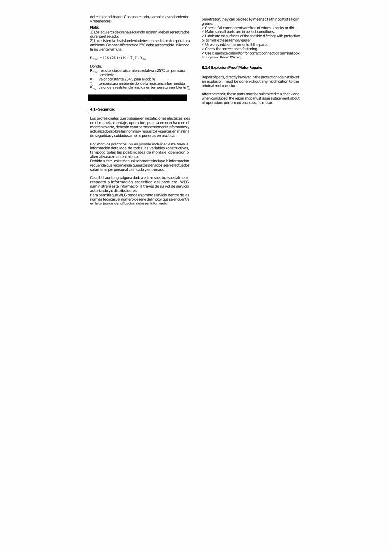
7/17/2019 R05323-P-001A-X009-0042.pdf
http://slidepdf.com/reader/full/r05323-p-001a-x009-0042pdf 99/463
penetration; they can be oiled by means of a thin coat of silicongrease.ü Check if all components are free of edges, knocks or dirt.ü Make sure all parts are in perfect conditions.ü Lubricate the surfaces of the endshield fittings with protectiveoil to make the assembly easier.ü Use only rubber hammer to fit the parts.ü Check the correct bolts fastening.ü Use clearance calibrator for correct connection terminal boxfitting (less than 0.05mm).
8.1.4 Explosion Proof Motor Repairs
Repair of parts, directly involved in the protection against risk of an explosion, must be done without any modification to theoriginal motor design.
After the repair, these parts must be submitted to a check andwhen concluded, the repair shop must issue a statement, aboutall operations performed on a specific motor.
del estator bobinado. Caso necesario, cambiar los rodamientosy retenedores.
Nota:
1) Los agujeros de drenaje (cuando existan) deben ser retiradosdurante el secado.2) La resistencia de aislamiento debe ser medida en temperaturaambiente. Caso sea diferente de 25°C debe ser corregida utilizandola siguiente formula:
R(25°C)
= [( K+25 ) / ( K + Ta )] . R
(Ta)
Donde:R
(25°C)resistencia del aislamiento relativa a 25°C temperaturaambiente
K valor constante 234.5 para el cobre T
atemperatura ambiente donde la resistencia fue medida
R(Ta)
valor de la resistencia medida en temperatura ambiente Ta
4. INSTALACION
4.1 - Seguridad
Los profesionales que trabajan en instalaciones eléctricas, sea
en el manejo, montaje, operación, puesta en marcha o en elmantenimiento, deberán estar permanentemente informados yactualizados sobre las normas y requisitos vigentes en materiade seguridad y cuidadosamente ponerlas en práctica.
Por motivos prácticos, no es posible incluir en este Manualinformación detallada de todas las variables constructivas,tampoco todas las posibilidades de montaje, operación oalternativas de mantenimiento.Debido a esto, este Manual solamente incluye la informaciónrequerida que recomienda que estos servicios sean efectuadossolamente por personal calificado y entrenado.
Caso Ud. aun tenga alguna duda a este respecto, especialmenterespecto a información especifica del producto, WEG
suministrará esta información a través de su red de servicioautorizado y/o distribuidores.Para permitir que WEG tenga un pronto servicio, dentro de lasnormas técnicas, el número de serie del motor que se encuentraen la tarjeta de identificación debe ser informado.

7/17/2019 R05323-P-001A-X009-0042.pdf
http://slidepdf.com/reader/full/r05323-p-001a-x009-0042pdf 100/463
9. WARRANTY TERMS
WEG warran ts i ts produc ts aga ins t defec t s in workmansh ip and materials for eighteen (18) months from the invoice date issued by the factory, authorized d istributor or agent limited to twenty four (24) months from manufacturing date independ ent of installation date as long as the following items are fulfi l led a c co r d i n g l y :
- Proper transportat ion, handl ing and storage; - Co r r e c t in s t a l l at i o n ba sed on t h e spe c i f i e d am b i e n t env ironmen ta l cond i t i ons ; - Operat ion under motor c apacity l imits; - Observat ion of the periodic al maintenanc e services; - Repair and/or replacement effected only by p ersonnel duly author ized in wri t ing b y WEG; - The failed product b e available t o the supplier and/or repair shop for a required period to detect the c ause of the fai lure and c o r respond ing repa i r ; - Imm ediate not ice by the purchaser about fai lures occurred and that these are acce pted by WEG as manufacturing defects.This warranty does not include d isassembly services at the purch aser facil it ies, transportation co sts with product, tickets,acco mmo da t i on and mea ls fo r techn i ca l pe rsonne l when requested by t he cus tomer .
The warranty service will be on ly carried out at WEG Authorized Repair Shops or at WEG’s facil it ies.Com ponents wh ose useful l i fe, under normal use, is shorter than the warranty period are not co vered by these warranty terms.The repair and/or replacemen t of parts or com ponents, when affected b y WEG and/or any WEG Authorized Repair Shop, will not give warranty extension.This const i tutes WEG’s only warranty in connec t ion with this sa le and the com pany wi l l have no ob l i ga t i on o r l i ab i l i t y wha t s oe ver t o peop l e , t h i r d pa r t i e s , o t h e r equ i pmen t o r ins ta l l a t ions , inc lud ing wi thou t l im i t a t i on , any c la ims fo r consequent ial damage s or labor cos ts .
Las resistencias de calentamiento nunca deben ser energizadasmientras el motor este operando.
Figura 1
Medición de la resistencia del aislamiento
Desconectar el motor de la red de energía antes de hacercualquier medición de la resistencia del aislamiento.Para evitar riesgo de descarga eléctrica, descargue los
terminales después de la medición.
Mida la resistencia del aislamiento antes de poner el motor enservicio y/o cuando haya indicios de humedad en el bobinado.
La resistencia, medida a 25ºC (77ºF), debe ser:
Ri ≥ (20 x U) / (1000 + 2P) [MΩ](Medido con MEGGER a 500 V c.c.);Donde U = tensión (V); P = potencia (kW).
Si la resistencia del aislamiento medida es inferior a 2 MΩ, elbobinado deberá ser secado de acuerdo con lo que sigue:Calentar el estator bobi nado en un horno partiendo de unatemperatura de 80ºC (176ºF) y elevando 5ºC (41ºF) por horahasta llegar a los 105ºC (221ºF); esta última temperatura debepermanecer durante un período mínimo de una hora.Medir se la resistencia del aislamiento del bobinado permanececonstante y con valores dentro de los mínimos recomendados;caso contrario, se deberá proceder a una nueva impregnación
Posición del Dreno
Dreno

7/17/2019 R05323-P-001A-X009-0042.pdf
http://slidepdf.com/reader/full/r05323-p-001a-x009-0042pdf 101/463
MANUAL DE INSTALACION,OPERACION Y
MANTENIMIENTO PARA
MOTORES DE INDUCCIONCarcasas 143/5t hasta 586/7
ü Verifique si ocurrieron daños durante el transporte.ü Verifique los datos de la tarjeta de identificación.üGire el eje con la mano para verificar si está girando libremente.ü Asegurar que el motor no tenga sido expuesto a polvo ohumedad durante el transporte a almacenamiento.
3. ALMACENAMIENTO
Si los motores no fueran inmediatamente instalados, deben ser
almacenados en un local seco, libre de polvo, vibraciones, gasesy vapores corrosivos; dotado de temperatura uniforme,colocándolos en posición normal y sin apoyar sobre ellos otrosobjetos.
La temperatura de almacenaje de los motores debe quedar entre41°F (5°C) y 140°F (60°C), con humedad relativa no excediendoa 50%.
En el caso de motores con más de dos años de almacenaje, sedebe proceder al cambio de rodamientos o a la substitucióntotal de la grasa lubricante después de la limpieza de los mismos.
En los motores monofásicos almacenados durante dos años omás, se debe además cambiar los capacitores (cuando existan).
WEG recomienda girar el eje del motor (manualmente) al menosuna vez al mes y medir la resistencia del aislamiento antes deinstalarlo, en caso de motores almacenados más de 6 meses ocuando están sometidos a ambientes con alta humedad.
Caso el motor dispone de resistencias de calentamiento, estasdeberán ser conectadas durante el periodo de almacenaje casola humedad relativa exceder 50%.
Caso el motor permanecer almacenado por un largo periodosin tener las resistencias de calentamiento conectadas o cuandoestán instaladas pero no en operación, humedad/agua en laparta interna del motor pueden condensar. En estos casos, laagua debe ser drenada removiendo los drenos (tapones)roscados. Después del drenaje hecho, conecte las resistenciasde calentamiento y asegure que el motor este completamenteseco, entonces reinstale los tapones (drenos) para asegurar elgrado de protección correcto. (Vea figura 1).
Transformando Energía en Soluciones

7/17/2019 R05323-P-001A-X009-0042.pdf
http://slidepdf.com/reader/full/r05323-p-001a-x009-0042pdf 102/463
LA INTENCION DE ESTE MANUAL ES PROVEER INFORMACIONES IMPORTANTES QUE DEBEN SER SEGUIDAS DURANTE TRANSPORTE, INSTALACION ,OPERACION Y MANTENIMIENTO DE LOS MOTORES
WEG. ENTONCES, RECOMENDAMOS LEER ATENTAMENTE ESTE MANUAL ANTES DE LAINSTALACION Y OPERACION DEL MOTOR.
PARA ASEGURAR INTEGRIDAD FISICA DE LAOPERACION Y PROTECCION MATERIAL, TODA LA
INFORMACION INCLUIDA EN ESTE MANUAL DEBERA
SER EXTREMAMENTE SEGUIDA
I
INDICE
1. MANEJO Y TRANSPORTE 2. VERIFICACION EN LA RECEPCION 3. ALMACENAMIENTO 4. INSTALACION
4.1 - Se g ur id ad 4.2 - Co n d ic i o n es d e o p e r a c ió n 4.3 - Fu n da c io n es d e l mo t o r 4.4 - A gu je ro s d e D r e na je 4.5 - B ala nc eo 4.6 - Al in ea c ió n 4.7 - Ac o p lam ie nt os 4 .8 - Conex ión e léct r i ca 4 .9 - Métodos de a r ranque 4 .10 - D ispos it i vo de p ro tecc ión 4.11 - Puesta en Marcha
5. MANTENIMIENTO 5.1 - L ub ri ca c ión 5.1.1 - Mo tores sin grasera 5.1 .2 - Motores con grasera 5.1.3 - Compatib i l idad d e la grasa MOBIL Pol i rex EM
con o tros t ipos de grasa 5.2 - DESMONTAJE Y MONTAJE
6. PARTES Y PIEZAS - REPUESTOS 7. MOTORES PARA USO CON CONVERTIDOR DE FRECUENCIA
7.1 - Mo to re s S ta nd a rd 7 .2 - Mo t o re s I nv er te r Du ty 7 .3 - A is lam i en t o de r odam ien to s
8. INFORMACIONES ADICIONALES 8 .1 - Mo to res pa ra Áreas de Riesgo 8.1 .1 - Gen era l 8.1.2 - Instalac ión 8 .1 .3 - Chequeo y Man ten imien to 8.1.4 - Reparos en Moto res a Prueba de Explosión
9. TERMINOS DE GARANTIA
1 – MANEJO Y TRANSPORTE
LOS MOTORES NO DEBEN SER IZADOS POR ELEJE, UTILIZE LOS CANCAMOS DE SUSPENSION,
ESPECIFICOS PARA ESTE PROPOSITO
LOS MOTORES CON RODAMIENTOS DE RODILLOS O DE CONTACTO ANGULAR ESTAN PROTEGIDOS,
DURANTE EL TRANSPORTE, CONTRA DAÑOS POR MEDIO DE UN D ISPOSITIVO DE BLOQUEO DEL EJE
LOS DISPOSITIVOS DE BLOQUEO DEBEN SER UTILIZADOS SIEMPRE QUE SE TRANSPORTE
EL MOTOR, AUNQUE ESTO IMPLIQUE TENERLO QUE DESACOPLAR NUEVAMENTE
DE LA MAQUINA ACCIONADA
Equipamientos de alzamiento, cuando suministrados, sonproyectados solamente para la sustentación del motor.Si el motor por su diseño constructivo tiene dos cáncamos de
suspensión, use dispositivos que permitan el izamiento porambos elementos al mismo tiempo.El izamiento así como el descenso del motor deben ser realizadosen forma suave, sin golpes, caso contrario los rodamientospueden sufrir daños.
I
I
I
2. VERIFICACION EN LA RECEPCION
· En la recepción del motor, verifique si ocurrieron daños duranteel transporte.
En el caso de verificar cualquier daño, avisar inmediatamente latransportadora, la compañía aseguradora y WEG. No avisar latransportadora, la compañía aseguradora y WEG puede resultaen la pérdida de la garantía del producto.
No remueva la grasa de protección de la punta de eje, tampoco lostapones que cierran los agujeros de la caja de conexiones, casoexistir. Estos ítems de protección deben ser mantenidos hasta quela instalación completa sea concluida. Después de la remoción desu embalaje, una completa inspección visual debe ser hecha en

7/17/2019 R05323-P-001A-X009-0042.pdf
http://slidepdf.com/reader/full/r05323-p-001a-x009-0042pdf 103/463
SHIJIAZHUANG KINGDA PUMP INDUSTRY GROUP CO., LTD
TOROMOCHO PROJECT
HARD METAL SLURRY PUMP
LONG-TERM STORAGE INSTRUCTIONS
Hard Metal Slurry Pumps
R05323-P-001A
SHIJIAZHUANG KINGDA PUMP INDUSTRY GROUP Co., Ltd
1st September, 2010

7/17/2019 R05323-P-001A-X009-0042.pdf
http://slidepdf.com/reader/full/r05323-p-001a-x009-0042pdf 104/463
SHIJIAZHUANG KINGDA PUMP INDUSTRY GROUP CO., LTDLONG-TERM STORAGE INSTRUCTIONS
TOROMOCHO PROJECTR05323-P-001A, REV A
1
LONG-TERM STORAGE INSTRUCTIONS
The pumps are shipped fully protected for the commercial shipping and handling that is required for a
given order. Upon receipt, it is necessary that the customer, or an agent of the customer, conduct a
thorough inspection of all pumps and components for completeness of delivery and possible handling
damage. Some small spare parts may be packed separately, if you find damage or loss, please contact
with Kingda and Freight Company immediately.
Al l shortages should be immediately reported to Kingda.
Note: Any components damaged in shipment should be noted and a claim filed by the responsib le
shipping party with the freight company.
Kinda does not warrant any pump or pump components which become damage due to a failure
which adhere to the instructions listed below.

7/17/2019 R05323-P-001A-X009-0042.pdf
http://slidepdf.com/reader/full/r05323-p-001a-x009-0042pdf 105/463
SHIJIAZHUANG KINGDA PUMP INDUSTRY GROUP CO., LTDLONG-TERM STORAGE INSTRUCTIONS
TOROMOCHO PROJECTR05323-P-001A, REV A
2
Outdoor Storage
1. Site selection for outdoor storage of pump and pump components as following:
1.1: Level, well-drained, firm surface, clean, and dry location.
1.2: The environment for pump storage must be dry, dust-free, and well-ventilated. Avoid damage the
bearing because of vibration. The vibration of the storage place is less than 0.2mm/S.
1.3: Isolated or barricaded from possibility of physical damage from transport vehicles, earth working
equipment, and other site erected equipment.
1.4: The inlets and outlets of pumps should be plugged to prevent sundries entering pump cavity.
Accessible for periodic inspection and maintenance.
2. All the pump or pump baseplate should be supported under each corner of its base to allow it to
“breathe”. Supports (steel beams or wood timbers) of significant size and strength should be placed under
each corner. All components shipped in crates and pallets must be located and supported such that air can flow under
and around the shipping container.
3. Upon receipt of the Pump and pump components, an initial inspection must be made to ensure that all
protective coatings and/or devices have not been compromised during shipping and handling.
If discrepancies are found, corrective action must be taken to ensure adequate protection of the
equipment during storage.
Particular attention must be paid to:
(a) All bright steel surfaces, journal and machined; such as shafts, end flanges.
(b) All shaft sleeve and bearing surfaces.
(c) All the roller bearing.
(d) All machined surfaces protected with paint
4. It is recommended that all electric motors be stored indoors. The motors are to be stored and protected
in accordance with the requirements of the motor manufacture. Some motors may have low voltage
internal heaters that are to be energized during storage.
If indoor store is not possible, it is necessary that these pumps and components be covered by a tarp
which is loose enough to let the component breathe. In areas of high relative humidity, it may be
necessary to use a desiccant to keep it free of moisture.
Note: WEG will provide the Motor Storage Instructions on all motors supplied by us.
Some motors may have low voltage internal heaters that are to be energized during storage.

7/17/2019 R05323-P-001A-X009-0042.pdf
http://slidepdf.com/reader/full/r05323-p-001a-x009-0042pdf 106/463
SHIJIAZHUANG KINGDA PUMP INDUSTRY GROUP CO., LTDLONG-TERM STORAGE INSTRUCTIONS
TOROMOCHO PROJECTR05323-P-001A, REV A
3
Covered or Indoor Storage
The pumps should be covered or Indoor Storage. Covered storage will consist of any structure with a roof
to protect pumps and pump components from direct sunshine and rain. Indoor storage will consist of a
closed-in structure that will protect from sun, rain, wind and dust.
It is recommended that all electric drive motors should be stored indoors. The motors are to be stored and
protected in accordance with the requirements of the motor manufacture.
If proper indoor storage is not available, then the sensitive components must be covered with a well
drained and ventilated tarp or tent structure.
Attention during Storage
1. If the storage time is not more than 1 month, It is suggested that the pump should rotate by 1/4 turn
by manual every 1 week.
2. If the storage time is longer than 1 month , it’s recommended that preservative oil is painted on the
inside of the pump. The preservative oil should be replaced every 12 month. (The preservative oil film
must be cleaned before the trial run of the pump).
It is suggested that the pump should rotate by 1/4 turn by manual every 1 week.
For the pumps with packing, if the storage time is too long, replace the old packing.
3. Check all the components every 3 months; if rusted or oxidized, clean the surface and repaint the
preservative oil.
PARTICULAR ATTENTION must be paid to following:
1. Machined surface of rotating parts, as shaft, shaft sleeve, etc.
2. All the roller bearings, adequate lubricating oil should be filled in it to minimize the chance of oxidization
or rust.
3. The temperature of storage environment should not be less than 5 centigrade. It is to prevent the left
water to cracking the water jacket freezingly in the low temperature condition.
4. Measure the insulating resistance of stator with megameter periodically to check if the motor is not
affected with dampness.
5. The end of cable should be packed with adhesive butyl tape to avoid the moisture entering into the
cable.
6. To avoid the quick aging, keep the cable, winding wire and rubber parts away from the direct sunlight,
heat and hot flame.
7. The technical documents should be safely kept from moisture.
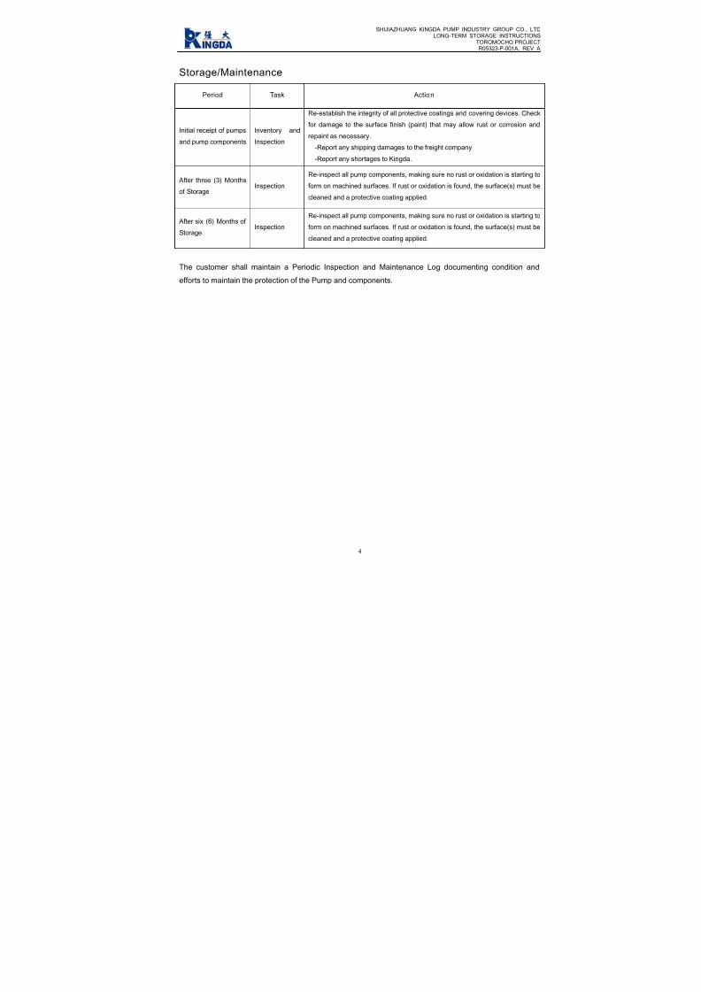
7/17/2019 R05323-P-001A-X009-0042.pdf
http://slidepdf.com/reader/full/r05323-p-001a-x009-0042pdf 107/463
SHIJIAZHUANG KINGDA PUMP INDUSTRY GROUP CO., LTDLONG-TERM STORAGE INSTRUCTIONS
TOROMOCHO PROJECTR05323-P-001A, REV A
4
Storage/Maintenance
Period Task Action
Initial receipt of pumps
and pump components
Inventory and
Inspection
Re-establish the integrity of all protective coatings and covering devices. Check
for damage to the surface finish (paint) that may allow rust or corrosion and
repaint as necessary.
-Report any shipping damages to the freight company.
-Report any shortages to Kingda.
After three (3) Months
of StorageInspection
Re-inspect all pump components, making sure no rust or oxidation is starting to
form on machined surfaces. If rust or oxidation is found, the surface(s) must be
cleaned and a protective coating applied.
After six (6) Months ofStorage
Inspection
Re-inspect all pump components, making sure no rust or oxidation is starting to
form on machined surfaces. If rust or oxidation is found, the surface(s) must be
cleaned and a protective coating applied.
The customer shall maintain a Periodic Inspection and Maintenance Log documenting condition and
efforts to maintain the protection of the Pump and components.
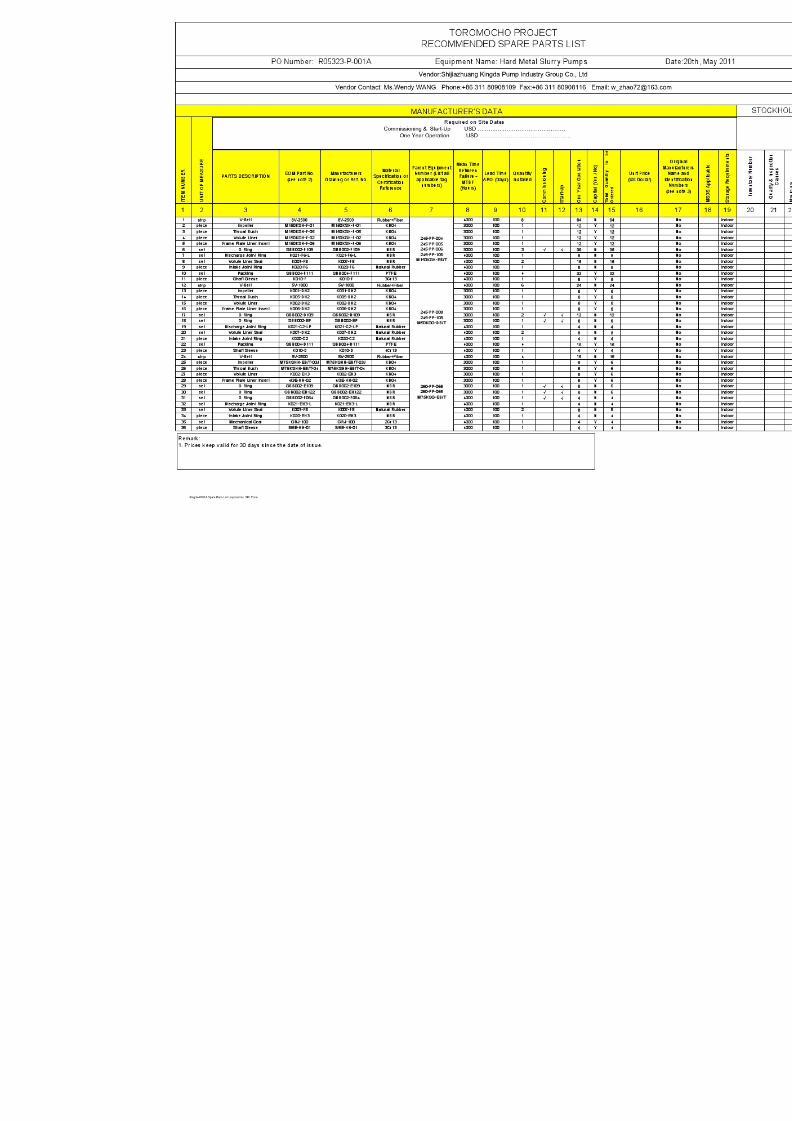
7/17/2019 R05323-P-001A-X009-0042.pdf
http://slidepdf.com/reader/full/r05323-p-001a-x009-0042pdf 108/463

7/17/2019 R05323-P-001A-X009-0042.pdf
http://slidepdf.com/reader/full/r05323-p-001a-x009-0042pdf 109/463
Toromocho Project
Lubrication Schedule
Vendor: Shijiazhuang Kingda Pump Industry Group Co., Ltd Date: 28th October, 2010
Equipment Name: Hard Metal Slurry Pumps PO No.: R05323-P-001A
Equipment No. Pump ModelPump Speed
(RPM)Lubricant Type
Lubricant
Manufacturer
Lubrica
Positio
245-PP-004/005/006/106 M150KSH-EB/T 810~1050
lithium grease #2 or #3 —— pump e
lithium grease #2 or #3 —— motor e
245-PP-008/108 M50KSG-DB/T 1350
lithium grease #2 or #3 —— pump e
lithium grease #2 or #3 —— motor e
260-PP-065/165 M75KSG-EB/T 1200~1280
lithium grease #2 or #3 —— pump e
lithium grease #2 or #3 —— motor e

7/17/2019 R05323-P-001A-X009-0042.pdf
http://slidepdf.com/reader/full/r05323-p-001a-x009-0042pdf 110/463
Tormocho Project
LUBRICATION SCHEDULE
PO Number: R05323-P-001 Equipment: Standard End Suction Pumps
Vendor :SHIJIAZHUANG KINGDA PUMP Vendor contact Name : Wang zhao(Wendy)
page 1 of 1 E-mail :[email protected]
EQUIP NO. DESCRIPTION, WHERE USED LUBRICANT TYPE QUANTITY MANUFACTURERF
R
245-PP-004
245-PP-005
245-PP-006
245-PP-106
Front bearing NU322-C3POLYREX EM
(polyurea grease
60g
MOBIL
Rear bearing 6319-C3 45g
245-PP-008/108Front bearing NU319-C3 POLYREX EM
(polyurea grease
45gMOBIL
Rear bearing 6316-C3 34g
260-PP-065/165Front bearing NU319-C3 POLYREX EM
(polyurea grease
45gMOBIL
Rear bearing 6316-C3 34g

7/17/2019 R05323-P-001A-X009-0042.pdf
http://slidepdf.com/reader/full/r05323-p-001a-x009-0042pdf 111/463

7/17/2019 R05323-P-001A-X009-0042.pdf
http://slidepdf.com/reader/full/r05323-p-001a-x009-0042pdf 112/463

7/17/2019 R05323-P-001A-X009-0042.pdf
http://slidepdf.com/reader/full/r05323-p-001a-x009-0042pdf 113/463
WEG INDÚSTRIAS S/A
ELECTRIC MOTOR WIRING DIAGRAM
• SINGLE SPEED 380V 60HZ MOTOR:

7/17/2019 R05323-P-001A-X009-0042.pdf
http://slidepdf.com/reader/full/r05323-p-001a-x009-0042pdf 114/463

7/17/2019 R05323-P-001A-X009-0042.pdf
http://slidepdf.com/reader/full/r05323-p-001a-x009-0042pdf 115/463
INDEX
Item No. Description
1 Datasheets (Pump & Motor), Performance Curve
2 Installation Drawing
3 Assembly Drawing
4 Lifting Diagram
5 ITP
6 Ultrasonic Flaw Detection Specification For Shaft Parts
7 Welding Process Specification
8 Material Report For Main Parts
9 Ultrasonic Flaw Detection Report
10 Inspection Report For Parts
11 Inspection Record For Assembly
12 Inspection Record For Painting
13 Inspection Record For Packing
14 Hydraulic Pressure Test Report
15 Performance Test Procedure
16 Performance Test Details Sheet
17 Performance Test Report
18 Vibration Report
19 Noise Report
20 Pump IOM
21 Motor IOM
22 Long Term Storage Instructions
23 Spare Parts List for Operation and 1 Year (Un-priced)
24 Pump Lubrication Schedule
25 Motor Lubrication Schedule
26 Packing List
27 Certification of Conformance
28 Motor Wiring Diagram

7/17/2019 R05323-P-001A-X009-0042.pdf
http://slidepdf.com/reader/full/r05323-p-001a-x009-0042pdf 116/463

7/17/2019 R05323-P-001A-X009-0042.pdf
http://slidepdf.com/reader/full/r05323-p-001a-x009-0042pdf 117/463
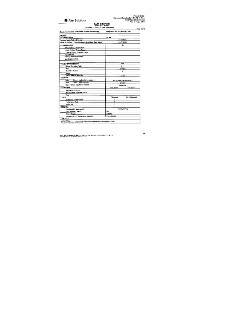
7/17/2019 R05323-P-001A-X009-0042.pdf
http://slidepdf.com/reader/full/r05323-p-001a-x009-0042pdf 118/463

7/17/2019 R05323-P-001A-X009-0042.pdf
http://slidepdf.com/reader/full/r05323-p-001a-x009-0042pdf 119/463

7/17/2019 R05323-P-001A-X009-0042.pdf
http://slidepdf.com/reader/full/r05323-p-001a-x009-0042pdf 120/463

7/17/2019 R05323-P-001A-X009-0042.pdf
http://slidepdf.com/reader/full/r05323-p-001a-x009-0042pdf 121/463

7/17/2019 R05323-P-001A-X009-0042.pdf
http://slidepdf.com/reader/full/r05323-p-001a-x009-0042pdf 122/463

7/17/2019 R05323-P-001A-X009-0042.pdf
http://slidepdf.com/reader/full/r05323-p-001a-x009-0042pdf 123/463

7/17/2019 R05323-P-001A-X009-0042.pdf
http://slidepdf.com/reader/full/r05323-p-001a-x009-0042pdf 124/463

7/17/2019 R05323-P-001A-X009-0042.pdf
http://slidepdf.com/reader/full/r05323-p-001a-x009-0042pdf 125/463

7/17/2019 R05323-P-001A-X009-0042.pdf
http://slidepdf.com/reader/full/r05323-p-001a-x009-0042pdf 126/463

7/17/2019 R05323-P-001A-X009-0042.pdf
http://slidepdf.com/reader/full/r05323-p-001a-x009-0042pdf 127/463
No. 239, Tianshan Street, Shijiazhuang City, Hebei Province, ChinaTel: +86 311 80908109 Fax: +86 311 80908116 Email: [email protected]
Inspection and Test Plan
PO No.: R05323-P-001A, Equipment Name: Hard Metal Slurry Pumps
Item
No.
Inspection &
Test Item
Acc eptance
Criteria
Inspection
Methods
Acceptance
Doc.
Review
Doc.
Executive
Time Ma
1 Acceptance of Contract Documents
1.1 Contract Inspection
Signed Contract and
Requirements
Check the Contract and
Requirements
Requirements
by the Contract
Vendor
Departm
1.2
Dimensional
Drawings
Certified Drawings and
Documents
Drawings and Document
Inspection
Drawings submitted
by Vendor
Vendor
Departm
2 Inspectio n on Raw Materials and Purchased Parts
2.1
Inspection of raw
materials
JB/T8096-1998
GB9439-1998
(ASTM A48-2003)
GB1348-1998
(ASTM A536-2003)
GB2100-2002
(ASTM A743/743a-1993a)
GB/T8263-1999
(ASTM A532M-99)
GB699-1988
(ASTM A36/A36M-2005)
SBB121.1-29-1997
SBB125.1-28-1997
SBB302.1-12-2008
SBB0158-2003
Visual inspection, Chemical test,
Spectrometer, General gauge
Comply with the
Standards
Material Composition
Analysis and Mechanical
Prosperities Report,
Product Compliance
Certificate
After arrival at
Factory
Quality
Dept.
2.2 Bearings
Contract Technical
Requirements
Visual inspection, check Product
Compliance Certificate
Comply with
Contract technical
Product Compliance
After arrival at
Factory
Quality
Manage

7/17/2019 R05323-P-001A-X009-0042.pdf
http://slidepdf.com/reader/full/r05323-p-001a-x009-0042pdf 128/463
No. 239, Tianshan Street, Shijiazhuang City, Hebei Province, ChinaTel: +86 311 80908109 Fax: +86 311 80908116 Email: [email protected]
requirement Dept.
2.3 WEG Motors
Contract Technical
Requirements
Visual inspection, check Product
Compliance Certificate
Comply with
Contract technical
requirement
Product Compliance
After arrival at
Factory
Quality
Manage
Dept.
3 Inspectio n and Test in Pump Product ion Process
3.1
Inspection Before
Casting
SBB139-2001
SBB131-1998
SBB122-2000
Spectrometer
Comply with the
Standards
Material Composition
Analysis and Mechanical
Prosperities Report
Before Pouring
Quality
Manage
Dept.
3.2 Castings
SBB139-2001
SBB122-2000
SBB131-1998
GB1348-1988
(ASTM A536-2003)
Spectrometer,
Carbon-Sulfur Analyzer,
Chemical Test, General Gauge
Comply with the
Standards
Material Composition
Analysis and Mechanical
Prosperities Report
After
heat treatment
Quality
Dept.
3.3 Heat TreatmentSBB131-1998
SBB165-2009
Hardness Tester,
Universal Tester
Comply with the
Standards
Heat Treatment
Report
After
heat treatment
Quality
Manage
Dept.
3.4
Inspection in
Machining Process
SBB2105-87
SBB061-2003
Drawing Requirements
General Tools,
Special Tools
Comply with the
Standards and
Drawing
Requirements
Machining Dimension
Inspection Record
During
Machining
Process
Quality
Manage
Dept.
3.5
Impeller Static
Balancing,
SBB061-2003 Balancing Test Frame
Comply with the
Standard
Impeller Static Blancing
Report
Static Balance
Test
Quality
Manage
Dept.
3.6 Shafft Inspection YB-T036.T-92 Ultrasonic Detection
Comply with the
Standard
Shaft Ultrasonics
Detection Report
Shaft Inspection
Test
Quality
Manage
Dept.
4 Assembl y, Test, Painting and Packing
4.1 Assembly SBB2103-2000 General Gauge
Comply with the
Standards and
Clearance Inspection
Record in Assembly
After Assembly
Quality
Dept.

7/17/2019 R05323-P-001A-X009-0042.pdf
http://slidepdf.com/reader/full/r05323-p-001a-x009-0042pdf 129/463
No. 239, Tianshan Street, Shijiazhuang City, Hebei Province, ChinaTel: +86 311 80908109 Fax: +86 311 80908116 Email: [email protected]
SBB064-2004
Drawing Requirements
Drawing
Requirements
4.2
Hydraulic
Pressure Test
GB/T5656-94,
SBB064-1998,
(HI 1.6-2000/API610)
Visual Inspection,
Pressure gauge
Comply with the
standards
Hydraulic Pressure Test
Report
After Assembly,
Witness Point
Quality
Dept.
4.3
Performance
Noise
Vibration
Contract Technical
Requirements
GB3216-2005
(HI 1.6-2000/
ASME B73.1M/B73.2M)
JB/T8097-1999
GB3214-91,
GB10890,
GB10889
SBB064-2004
Pump Test Station
Comply with the
Standards and
Contract Technical
Requirements
Pump Performance
Running Test Report
After Assembly,
Witness Point
Quality
Dept.
4.4 Painting
Contract Technical
Requirements SBB097-2008
SBB0159-1998
JB/T4297-1992
Visual Inspection,
Coating Thickness Meter
Comply with the
Standards and
Contract Technical
Requirements
Assembly Inspection
Record
After Painting
Quality
Dept.
4.5 Packing
Contract Technical
Requirements
SBB0157-1997
SBB0167-2009
GB/T13384-1992
Visual Inspection
Comply with the
Standards and
Contract Technical
Requirements
Assembly Inspection
Record
After Packing
Quality
Dept.
5 Relese for Shippment
5.1
Release for
shipment
Contract requirements As per Contract Requirements
Release for
shipment from
Owner
Hold Point

7/17/2019 R05323-P-001A-X009-0042.pdf
http://slidepdf.com/reader/full/r05323-p-001a-x009-0042pdf 130/463
ULTRASONIC FLAW DETECTION
SPECIFICATION
FOR
SHAFT PARTS
TOROMOCHO PROJECT
Supplier: SHIJIAZHUANG KINGDA PUMP INDUSTRY GROUP CO., LTD
Reviewed And Approved:
Date: November, 2011

7/17/2019 R05323-P-001A-X009-0042.pdf
http://slidepdf.com/reader/full/r05323-p-001a-x009-0042pdf 131/463
SHIJIAZHUANG KINGDA PUMP INDUSTRY GROUP CO., LTDULTRASONIC FLAW DETECTION SPECIFICATIONDoc No.: WPS-UD-2011, Date: Nov, 2011, Rev 00
NO. 239, TIANSHAN STREET, SHIJIAZHUANG CITY, HEBEI PROVINCE, CHINA
GENERAL TECHNICAL SPECIFICATION
FOR ULTRASONIC FLAW DETECTIOIN FOR SHAFT PARTS
1. General Provision
1.1 Application Scope
This Specification applies for the testing of internal incontinuity of forgings sourced by Kingda by using A
Type Pulse Reflection Ultrasonic Detection method.
This Specification is not applied to work piece of austenite coarse grained.
1.2 Acceptance Standard
GB/T 4162 Forged And Rolled Steel Bars - Method For Ultrasonic Testing
GB/T 7736 Ultrasonic Inspecting Method For Macro-Structure And Imperfection Of Steel
1.3 If special requirements, inspection and acceptance will be carried as per Standards in relative
agreements, drawing and process.
1.4 Requirements for Inspectors
The inspectors should have Ultrasonic Flaw Detection Technology Certification, and the Inspector who will
sign the Report must be qualified for II Grade or Above Certification.
2. Detection Equipment And Instruments
2.1 Ultrasonic Flaw Detector
The ultrasonic flaw detector should be tested for its fuction as per the methods specified in JB/T
10061-1999, and its quota should be meet following:
a). Surplus Sensitivity: N≥36dB
b). Vertical Linearity Tolerance: D≤6%
c). Horizontal Linearity Tolerance: δ≤1%
d). Dynamic Range: ≥30dB.
2.2 Probe
Usually straight beam probe is selected for detection; angle beam probe is selected for assistant detection.
The operation frequency of probe must meet the requirements to penetrate and explore the work piece,
nominal frequency of 2-5MHz is used, and probe crystal diameter or side length is 10-25mm.
2.3 Coupling Medium
Coupling medium whichever can give good coupling effect and is not harmful to body and work piece
should be selected.
The same coupling medium must be used for adjustment, calibration and inspection of equipments.

7/17/2019 R05323-P-001A-X009-0042.pdf
http://slidepdf.com/reader/full/r05323-p-001a-x009-0042pdf 132/463
SHIJIAZHUANG KINGDA PUMP INDUSTRY GROUP CO., LTDULTRASONIC FLAW DETECTION SPECIFICATIONDoc No.: WPS-UD-2011, Date: Nov, 2011, Rev 00
NO. 239, TIANSHAN STREET, SHIJIAZHUANG CITY, HEBEI PROVINCE, CHINA
2.4 Test Block
When test forged parts, the test block should be selected according to probe and condition of surface to be
detected, for example, CSI standard test block.
Equipment can also be adjusted according to test block as per GB/T 4162 or GB/T 7736.
3. Detection
3.1 Detection Method
Detection method is generally P-wave reflection, SH-wave reflection can be added if necessary.
A: Necessary detecting direction
B: Detecting direction which needs to be negotiated
Detection At Axial And Circumferential Direction For Shaft Parts
3.2 Detection Time
Usually the detection should be carried after entry of source parts into plant or after heat treatment.
If there any special requirements, the detection should be carried as per special time.
3.3 Detection Procedure
3.3.1 Treatment on Surface of Work Piece
Usually the roughness of surface of work piece should be R0≤6.3μm; Roughness may be enlarged for
coarse surface, but not more than 12.5μm.
The flaws as mill scale, dirties, paint and pit which can influence the acoustic coupling must be removed or
machined.
3.3.2 Adjustment of Instrument
3.3.2.1 Adjustment of Scan Speed
Generally it is required that forward base of first bottom wave should be not more than 80% of width of
oscilloscope screen in order to observe the situation of other signals after first bottom wave.
3.3.2.2 Adjustment of Sustained Sensitivity
For the work piece with thickness of position tested ≥3N, bottom wave adjustment method can be used;
For the work piece with thickness of position tested <3N or the surface is very rough, test pad adjustment

7/17/2019 R05323-P-001A-X009-0042.pdf
http://slidepdf.com/reader/full/r05323-p-001a-x009-0042pdf 133/463
SHIJIAZHUANG KINGDA PUMP INDUSTRY GROUP CO., LTDULTRASONIC FLAW DETECTION SPECIFICATIONDoc No.: WPS-UD-2011, Date: Nov, 2011, Rev 00
NO. 239, TIANSHAN STREET, SHIJIAZHUANG CITY, HEBEI PROVINCE, CHINA
method can be used.
When the surface shape and roughness of test pad is different from the work piece, coupling compensation
and attenuation compensation methods can be used.
3.3.2.3 Adjustment of Scan Sensitivity
6dB should be amplified based on the inspection sensitivity in order to easily find the defects, but estimation
on the defects should be based on the inspection sensitivity level.
3.4 Inspection Frequency
3.4.1 If no special requirement, the sample test should be made as per SBB302.1-2008.
3.4.2 If any special requirements, the test should be made as per requirements.
3.4.3 For the tested work piece, whole detecting should be made.
3.5 Scan Detection
3.5.1 Scan Type
Usually whole scan should be used.
3.5.2 Scan Speed
In order to ensure the defects can be clearly found, the scan speed should not more than 150mm/s.
3.5.3 Scan Distance
It is required that 15% overlapping should be done between two scans.
3.6 Calibration of Instruments
After detection, the instrument should be calibrated for sensitivity; if the sensitivity can not meet the
requirements, calibration should be done.
4. Estimation of Defects
Usually defects will be estimated according to the reflection and bottom reflection results, including defect
position and size, if necessary, the nature of defects can be estimated.
4.1 Estimation of Defect Position
To determine the surface position of defect according to the probe work position;
To determine he depth of defects according to that tested in oscilloscope screen.
4.2 Estimation of Defect Size
4.2.1 For flat defect of small wafer size, equivalent size of defect should be estimated according to the echo
margin shown in oscilloscope screen.
4.2.2 For flat defect of large wafer size, the length and area of defect should be estimated by 6dB or half
wave height method.

7/17/2019 R05323-P-001A-X009-0042.pdf
http://slidepdf.com/reader/full/r05323-p-001a-x009-0042pdf 134/463
SHIJIAZHUANG KINGDA PUMP INDUSTRY GROUP CO., LTDULTRASONIC FLAW DETECTION SPECIFICATIONDoc No.: WPS-UD-2011, Date: Nov, 2011, Rev 00
NO. 239, TIANSHAN STREET, SHIJIAZHUANG CITY, HEBEI PROVINCE, CHINA
4.2.3 For the defect of volume type, circumferential direction detection method can be used.
5. Quality Estimation
Estimation should be made as per GB/T 4162 and GB/T 7736; if any, special requirements can be followed.
After the detection, if disputes, it can be confirmed by low-power etch test.
6. Inspection Record And Report
6.1 Inspection report include: specification, grade, heat number, standard, quality grade and quantity,
issued by who and date, etc.
6.2 Inspection record should include position of defect, size of equivalent, distance and length of defects,
and drop of bottom wave, etc.

7/17/2019 R05323-P-001A-X009-0042.pdf
http://slidepdf.com/reader/full/r05323-p-001a-x009-0042pdf 135/463

7/17/2019 R05323-P-001A-X009-0042.pdf
http://slidepdf.com/reader/full/r05323-p-001a-x009-0042pdf 136/463
SHIJIAZHUANG KINGDA PUMP INDUSTRY GROUP CO., LTD
WELDING PROCESS SPECIFICATION FOR REPAIR OF CASTINGS
Doc No.: WPS-KD-2011, Date: Oct, 2011, Rev 00
NO. 239, TIANSHAN STREET, SHIJIAZHUANG CITY, HEBEI PROVINCE, CHINA
Process Specification of Welding
1. Preparation Before Welding
1.1 Operator must be very well acquainted with the drawings, process specification and relative
documents.
1.2 Operator must carefully check the material grades and dimensions of parts and casting
which are going to be welded.
1.3 Calibers and scales must be marked with inspection certificate. The tools and auxiliary
devices must be reliable.
1.4 The welding machine must be in good condition, grounding and good in insulation.
1.5 Select welding materials as per specification.
1.6 Welding rods must be complete dry, if the rods are wet, make dry treatment as following
table:
Dry Methods for Welding Rod
Type of Rod Dry Temperature () Dry Time (hour)
acid-type 70~150 1~1.5
alkaline-type 250~350 1~2
Note: usually, the acid rod may not be dried before using, the alkaline rod (including S.S. rod) must be dried
treatment before using.
2. Welding
2.1 Clear water, oil stain, rust and burrs within 20mm to 30mm at two sides of weld seam and
bevel before welding.
2.2 For the parts to be beveled, the shape and dimension of bevel should conform to GB985-88
Standard.
2.3 Select welding rod as following Specification Table:
Selection of Welding Rod
Thickness of Welding Part (mm) Diameter of Rod (mm)
≤4
4~12
>12
≤3.2
3.2~4.0
≥4.0
2.4 Welding Current Selection of Common Welding Rod as following:
Reference Current (A)

7/17/2019 R05323-P-001A-X009-0042.pdf
http://slidepdf.com/reader/full/r05323-p-001a-x009-0042pdf 137/463
SHIJIAZHUANG KINGDA PUMP INDUSTRY GROUP CO., LTD
WELDING PROCESS SPECIFICATION FOR REPAIR OF CASTINGS
Do .: WPS-KD-2011, Date: Oct, 2011, Rev 00
NO. 239, TIANSHAN STREET, SHIJIAZHUANG CITY, HEBEI PROVINCE, CHINA
c No
Rod Dia.
(mm)
Welding Grade
2.5 3.2 4.0 5.0
E4303 70~90 90~130 160~220 220~270
E4303 70~90 90~130 160~190 180~230
Note: upper limit for thick plate; the current of horizontal welding is about 10% less than downward welding.
2.5 General Principle for Welding Procedure
2.5.1 It must not produce rigid constraint force against the others of welding seam at the
beginning welding.
2.5.2 One end of each seam should be kept shrink freely at welding.
2.5.3 If the seam length is ≤1000mm for manual arc welding, generally continuous straight
welding method is used; back-step welding or section back-step welding may be used when
length is ≥1000mm.
2.6 Generating the arc: it is forbidden to generate the arc on the machined surface and locating
surface; the arc should be generated on the run-on plate and then transit to workpiece.
2.7 Arc Manipulation
2.7.1 Screw type is suitable for the first layer with any welding position and thin plate welding.
2.7.2 Wave type is suitable for the surface welding of downward welding, horizontal welding,
and overhead welding.
2.7.3 “8” shape type is suitable for downward and surface welding.
2.7.4 Zigzag type is suitable for horizontal welding.
2.8 Welding: before welding, the current should be regulated on the test plate till the current is
suitable.
2.8.1 Downward welding: the welding seam is at on horizontal level. arc manipulation should be
steady and fully fill the arc crater.
2.8.2 Vertical welding: the welding seam is vertical to the level ground. When vertical welding,
short arc small current should be used, don’t swing the rod bigly.
2.8.3 Overhead welding and horizontal welding: welding seam is horizontal or overhead
position. Shortest arc and smallest current should be kept to ensure fused drop transmitted to
metal.
2.9 Correction and Cleaning of Weldment
7/17/2019 R05323-P-001A-X009-0042.pdf
http://slidepdf.com/reader/full/r05323-p-001a-x009-0042pdf 138/463
SHIJIAZHUANG KINGDA PUMP INDUSTRY GROUP CO., LTD
WELDING PROCESS SPECIFICATION FOR REPAIR OF CASTINGS
Doc No.: WPS-KD-2011, Date: Oct, 2011, Rev 00
NO. 239, TIANSHAN STREET, SHIJIAZHUANG CITY, HEBEI PROVINCE, CHINA
2.9.1 Make the correction on the deforms produced in welding with flame correction or
mechanical correction.
2.9.2 Clean spatters, slags and flashes after welding.
2.9.3 The key parts and rigid parts should be distressing tempering treatment after welding.
3. Quality Requirements
3.1 Inspect the weldments for surface appearance and quality as per drawing and specification.
3.2 Welding seam should conform to Welding Seam Quality Standard.

7/17/2019 R05323-P-001A-X009-0042.pdf
http://slidepdf.com/reader/full/r05323-p-001a-x009-0042pdf 139/463
SHIJIAZHUANG KINGDA PUMP INDUSTRY GROUP CO., LTD
WELDING PROCESS SPECIFICATION FOR REPAIR OF CASTINGS
Doc No.: WPS-KD-2011, Date: Oct, 2011, Rev 00
NO. 239, TIANSHAN STREET, SHIJIAZHUANG CITY, HEBEI PROVINCE, CHINA
Process Specification for Weld Repair of Iron Casting
1. Permission Condition for Welding Repair
1.1 When the castings need to be welded repair, it must be approved by Quality Management
Department.
1.2 The permissive condition for the casting welded repair should conform to SBB122 <Pump
Casting Technical Conditions>, drawing and requirements in Contract.
2. Selection of Welding Method
Generally arc welding is used for casting weld repair, arc welding is divided into cold welding
and heat welding.
Application Range: Generally, welding repair will be used at non-machined position which has
low requirement for stress or strength or for defects found in and after machining or fine
machining. Because the correction of heat treatment after weld repair can not be used, in the
condition that its function (quality and precision) will not be influenced by the deformation or
stress caused by partial heating, cold arc welding may be used; when the heating material will
easily crack, heat arc welding can be used.
For iron casting, cold arc welding usually is used.
3. Preparation before Welding
3.1 Clean up the impurities at defect of casting with shovel, chisel, grinding wheel or other
methods, make it to be V shape with 60-80° or X bevel to expose the metal, sharp angle must
be rounded. All existing web cracks were arrested by drilling 4-8mm holes at the ends of the
cracks.
3.2 Remove the oil dirty at and around the defects with solution or flame.
3.3 Brush muddy water all around defect to avoid weld drop attach the machined surface.
3.4 Use Z308 pure nickel rod (Ф3.2, Ф4.2), this rod is required to be kept for 1 hour at temperature of
80-120.
3.5 Generally, preheating is not required for cold arc welding; if preheating required, written
approval must be obtained from Quality Department.
4. Welding Repair
4.1 Selection of Rod Diameter and Welding Current
Rod Diameter (mm) Welding Current (A)

7/17/2019 R05323-P-001A-X009-0042.pdf
http://slidepdf.com/reader/full/r05323-p-001a-x009-0042pdf 140/463
SHIJIAZHUANG KINGDA PUMP INDUSTRY GROUP CO., LTD
WELDING PROCESS SPECIFICATION FOR REPAIR OF CASTINGS
Doc No.: WPS-KD-2011, Date: Oct, 2011, Rev 00
NO. 239, TIANSHAN STREET, SHIJIAZHUANG CITY, HEBEI PROVINCE, CHINA
Ф3.2 70-100
Ф4.2 100-140
4.2 The seams should be successively welded layer by layer. Welding length of single layer is
10-15mm, beat the welding seam with 0.5-1.0 kg hammer to make the seam to be spot shape;
after the temperature of welded position is cooled down to 100, then proceed to welding.
When the welding repair is multi-layer, repeat the operation as single layer welding.
5. Cleaning After Welding
Trim the welding seam on the machined and nonmachined surface with grinding wheel, and
clear the weld drop on the casting and machined surface.
6. Inspection After Welding
6.1 For the requirements of relieving of stress, make inspection after the heat treatment.
6.2 Inspect the grinded effect of welded position to check if it can meet the requirements for
welding repair.
6.3 If the welding position is on non machined surface, check if the welded position is as smooth
as casting itself.
6.4 If the welding position is on the machined surface, check if the welded junction can meet
the requirements of machining.
6.5 Besides required NDT, usually visual inspection is just needed to conform if the weld repairs
meet the quality requirements, defects are left after welding.
6.6 For the casting sustaining the liquid pressure or air pressure, the air tight hydrostatic test
or gas inspection.

7/17/2019 R05323-P-001A-X009-0042.pdf
http://slidepdf.com/reader/full/r05323-p-001a-x009-0042pdf 141/463

7/17/2019 R05323-P-001A-X009-0042.pdf
http://slidepdf.com/reader/full/r05323-p-001a-x009-0042pdf 142/463

7/17/2019 R05323-P-001A-X009-0042.pdf
http://slidepdf.com/reader/full/r05323-p-001a-x009-0042pdf 143/463

7/17/2019 R05323-P-001A-X009-0042.pdf
http://slidepdf.com/reader/full/r05323-p-001a-x009-0042pdf 144/463

7/17/2019 R05323-P-001A-X009-0042.pdf
http://slidepdf.com/reader/full/r05323-p-001a-x009-0042pdf 145/463

7/17/2019 R05323-P-001A-X009-0042.pdf
http://slidepdf.com/reader/full/r05323-p-001a-x009-0042pdf 146/463
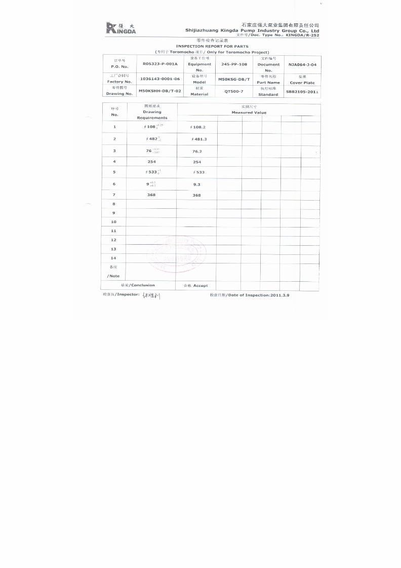
7/17/2019 R05323-P-001A-X009-0042.pdf
http://slidepdf.com/reader/full/r05323-p-001a-x009-0042pdf 147/463

7/17/2019 R05323-P-001A-X009-0042.pdf
http://slidepdf.com/reader/full/r05323-p-001a-x009-0042pdf 148/463

7/17/2019 R05323-P-001A-X009-0042.pdf
http://slidepdf.com/reader/full/r05323-p-001a-x009-0042pdf 149/463

7/17/2019 R05323-P-001A-X009-0042.pdf
http://slidepdf.com/reader/full/r05323-p-001a-x009-0042pdf 150/463

7/17/2019 R05323-P-001A-X009-0042.pdf
http://slidepdf.com/reader/full/r05323-p-001a-x009-0042pdf 151/463

7/17/2019 R05323-P-001A-X009-0042.pdf
http://slidepdf.com/reader/full/r05323-p-001a-x009-0042pdf 152/463

7/17/2019 R05323-P-001A-X009-0042.pdf
http://slidepdf.com/reader/full/r05323-p-001a-x009-0042pdf 153/463

7/17/2019 R05323-P-001A-X009-0042.pdf
http://slidepdf.com/reader/full/r05323-p-001a-x009-0042pdf 154/463

7/17/2019 R05323-P-001A-X009-0042.pdf
http://slidepdf.com/reader/full/r05323-p-001a-x009-0042pdf 155/463
1
水泵 能试验程
Performance Test Procedure of Centrifugal Pump
一、试验前准备
1.确定试验项目;
2.确定试验依据、判定标准;
3.确定试验场地、选择试验台位;
1. Preparation before Test
1.1 Define items to be tested;
1.2 Define test criteria and acceptance standard
1.3 Define test field and select test bed
二、组装台位
1.安装泵、电机(减速机)、进出口管线; 2.接压力测量表、流量测量表、电测表;
3.接轴封水,电机装防水设备;
4.电机接动力线,试转,并贴转速感光纸;
2. Install Pump on Test Bed
2.1 Install pump, motor (if any, gear box), pump intake pipe and discharge pipe;
2.2 Connect pressure gauge, flow meter and electrical meters;
2.3 Connect shaft seal water, cover the motor with water-proof facilities;
2.4 Connect power supply cable with motor, make trial running, and paste
light-sensitive paper for speed.
三、试验
1.运转试验检查轴承温升、轴封泄漏、振动、噪声情况;
2.记录进出口压力、流量、电流、电压、功率、转速等数据;
3.绘制性能曲线;
4.对试验结果作出判定。
3. Test
3.1 Start the test, check rise in bearing temperature, leakage of shaft seal, vibration,
and noise;
3.2 Record pressure of suction and discharge, flow rate, current, voltage, power,
speed, etc;
3.3 Draft performance curve;
3.4 Make judgment on the test result.

7/17/2019 R05323-P-001A-X009-0042.pdf
http://slidepdf.com/reader/full/r05323-p-001a-x009-0042pdf 156/463

7/17/2019 R05323-P-001A-X009-0042.pdf
http://slidepdf.com/reader/full/r05323-p-001a-x009-0042pdf 157/463

7/17/2019 R05323-P-001A-X009-0042.pdf
http://slidepdf.com/reader/full/r05323-p-001a-x009-0042pdf 158/463

7/17/2019 R05323-P-001A-X009-0042.pdf
http://slidepdf.com/reader/full/r05323-p-001a-x009-0042pdf 159/463

7/17/2019 R05323-P-001A-X009-0042.pdf
http://slidepdf.com/reader/full/r05323-p-001a-x009-0042pdf 160/463
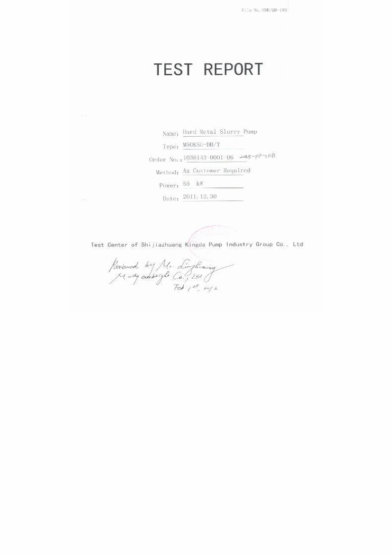
7/17/2019 R05323-P-001A-X009-0042.pdf
http://slidepdf.com/reader/full/r05323-p-001a-x009-0042pdf 161/463

7/17/2019 R05323-P-001A-X009-0042.pdf
http://slidepdf.com/reader/full/r05323-p-001a-x009-0042pdf 162/463

7/17/2019 R05323-P-001A-X009-0042.pdf
http://slidepdf.com/reader/full/r05323-p-001a-x009-0042pdf 163/463

7/17/2019 R05323-P-001A-X009-0042.pdf
http://slidepdf.com/reader/full/r05323-p-001a-x009-0042pdf 164/463

7/17/2019 R05323-P-001A-X009-0042.pdf
http://slidepdf.com/reader/full/r05323-p-001a-x009-0042pdf 165/463

7/17/2019 R05323-P-001A-X009-0042.pdf
http://slidepdf.com/reader/full/r05323-p-001a-x009-0042pdf 166/463

7/17/2019 R05323-P-001A-X009-0042.pdf
http://slidepdf.com/reader/full/r05323-p-001a-x009-0042pdf 167/463

7/17/2019 R05323-P-001A-X009-0042.pdf
http://slidepdf.com/reader/full/r05323-p-001a-x009-0042pdf 168/463
性能试验 息表
Test Details Sheet
1 泵 息/ Pump Details
订单号
P.O. No.:
R05323-P-001A 设备工位号
Equipment No.
245-PP-108 文件编号
Doc. No.
NJA064
强大合同号
Kingda Contract No.
1036143-0001-06 泵型号
Pump Model
M50KSG-DB/T
2 电机 息/Motor Details
制造者
Make
WEG 电机编号
Serial No.
1010566618 电机工位号
Motor No.
245-PP-108-M1
电机型号
Motor Model
444/5T 电机等级
Motor Rating
55KW 电机转速
Motor Speed
1785
3 试验 息/Test Details
测试开始时间
Pump Started
10:00 测试结束时间
Pump Stopped
11:00 试验日期
Test Date
2011.12.30
轴承温度
Bearing Temp.
42 环境温度
Ambient Temp.
16 水温
Water Temp.
13
4 试验性能参数 证/Performance Test Data Tolerance & Standard
参数名称/Parameter 流量/Flow 扬程/Head 效率/Efficiency 标准依据/Standard: ANSI/HI 1.6-B
5机械运行公差
Mechanical Run Tolerance & Standard
5.1 振动/Vibration 标准依据/Standard: JB/T8097-1999
5.2 噪声级别/Noise Level
参考合同规范 /As per Order Spec.: 最大 85dbA/Max 85
dB(A)
5.3 温升标准/Rise in Temp. Acceptance
标准依据/Standard: JB/T8096-1998
测试后温度 /Measured Temp.

7/17/2019 R05323-P-001A-X009-0042.pdf
http://slidepdf.com/reader/full/r05323-p-001a-x009-0042pdf 169/463
SERIES (M/R) KSH/KSG SLURRY PUMP
INSTALLATION, OPERATION AND MAINTENANCE
MANUAL
SHIJIAZHUANG KINGDA PUMP INDUSTRY GROUP CO.,LTD
2010

7/17/2019 R05323-P-001A-X009-0042.pdf
http://slidepdf.com/reader/full/r05323-p-001a-x009-0042pdf 170/463
Series (M/R) KSH/KSG Slurry PumpInstallation, Operation & Maintenance Manual
Shijiazhuang Kingda Pump Industry Group Co.,Ltd
1
Content
1. General Introduction…………………………….……………………………….…..2
2. Construction…………………………….…………………………………………………3
3. Installation…………………………………………………………………………………..6
4. Operation………………………………………………………………………….……….12
5. Maintenance……………………………………………………………………………….17
6. Possible Failures, Cause and Solutions……………………………….…………..20

7/17/2019 R05323-P-001A-X009-0042.pdf
http://slidepdf.com/reader/full/r05323-p-001a-x009-0042pdf 171/463
Series (M/R) KSH/KSG Slurry PumpInstallation, Operation & Maintenance Manual
Shijiazhuang Kingda Pump Industry Group Co.,Ltd
1 . GENERAL I N TRODUCT I ON
Series (M/R) KSH/KSG Pump is also called “High Efficiency Slurry Pump”. Because these pumps
are fitted with thick wear-resistant parts and heavy frame, so they are suitable to pump the slurry
of highly abrasion, high or low content and high head. During the max permissible working
pressure range, these pumps can be operated in serial. They also can transport the corrosive
slurries.
TYPE DEMONSTRATION:
2
Frame Type/Lubrication Type
Pump Type
Pump Discharge Diameter. (mm)
Metal Lined/Rubber Lined
Example: M200KSH (/KSG)-FA (/B)
M/R M for Metal Liner, R for Rubber Liner
200 Discharge Diameter is 200 mm
KSH Kingda Heavy-duty Slurry Pump
KSG Kingda High-head Slurry Pump
F Frame Type
A/B A for oil lubrication, B for grease lubrication
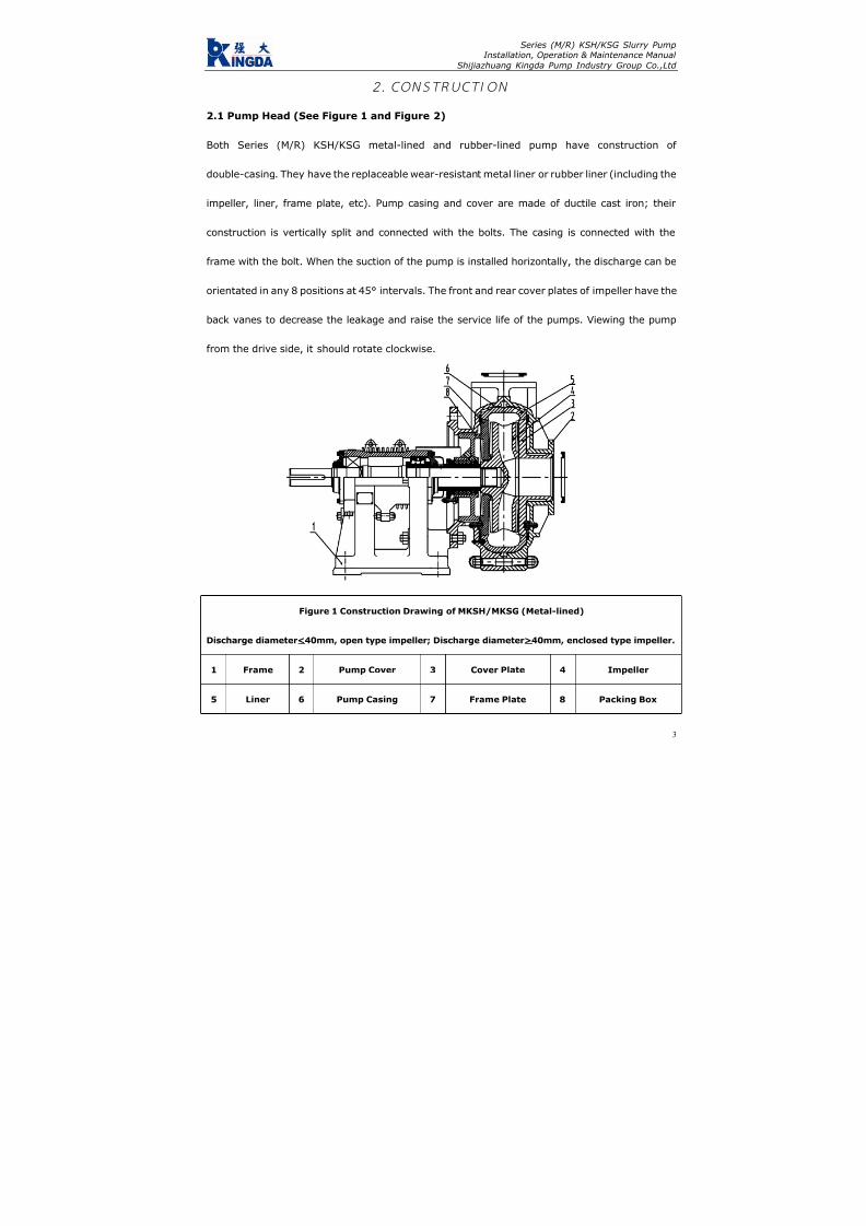
7/17/2019 R05323-P-001A-X009-0042.pdf
http://slidepdf.com/reader/full/r05323-p-001a-x009-0042pdf 172/463
Series (M/R) KSH/KSG Slurry PumpInstallation, Operation & Maintenance Manual
Shijiazhuang Kingda Pump Industry Group Co.,Ltd
2 . CONSTRUCT I ON
2.1 Pump Head (See Figure 1 and Figure 2)
Both Series (M/R) KSH/KSG metal-lined and rubber-lined pump have construction of
double-casing. They have the replaceable wear-resistant metal liner or rubber liner (including the
impeller, liner, frame plate, etc). Pump casing and cover are made of ductile cast iron; their
construction is vertically split and connected with the bolts. The casing is connected with the
frame with the bolt. When the suction of the pump is installed horizontally, the discharge can be
orientated in any 8 positions at 45° intervals. The front and rear cover plates of impeller have the
back vanes to decrease the leakage and raise the service life of the pumps. Viewing the pump
from the drive side, it should rotate clockwise.
Figure 1 Construction Drawing of MKSH/MKSG (Metal-lined)
Discharge diameter<40mm, open type impeller; Discharge diameter>40mm, enclosed type impeller.
1 Frame 2 Pump Cover 3 Cover Plate 4 Impeller
5 Liner 6 Pump Casing 7 Frame Plate 8 Packing Box
3

7/17/2019 R05323-P-001A-X009-0042.pdf
http://slidepdf.com/reader/full/r05323-p-001a-x009-0042pdf 173/463
Series (M/R) KSH/KSG Slurry PumpInstallation, Operation & Maintenance Manual
Shijiazhuang Kingda Pump Industry Group Co.,Ltd
Figure 2 Construction Drawing of RKSH/RKSG (Rubber-lined)
Discharge diameter<40mm, open type impeller; Discharge diameter>40mm, enclosed type impeller.
1 Frame 2 Pump Cover 3 Cover Plate (R) 4 Impeller
5 Cover Liner 6 Pump Casing 7 Frame Liner 8 Packing Box
2.2 Shaft Seal
There three types of shaft seals, packing seal, expeller seal and mechanical seal.
(1) Packing Seal: simple construction and easy maintenance. Shaft seal water is required. For the
condition which does not need the expeller seal, the packing seal can be used.
(2) Expeller Seal: Expeller seal can be used on the single stage pump or the first stage pump in
serial when the suction positive pressure is not more than the discharge pressure by 10%. The
expeller seal does not require the shaft seal water, and the slurry will not be diluted, which can
reach good sealing effect.
(3) Mechanical Seal: Mechanical seal features for highly wear resistant and shock resistance. It
can get non-leak sealing effect under various bad conditions, and be easily installed and
4

7/17/2019 R05323-P-001A-X009-0042.pdf
http://slidepdf.com/reader/full/r05323-p-001a-x009-0042pdf 174/463
Series (M/R) KSH/KSG Slurry PumpInstallation, Operation & Maintenance Manual
Shijiazhuang Kingda Pump Industry Group Co.,Ltd
5
replaced.
2.3 Transmission Part
During the bearing assembly of (M/R) KSH/KSG Pump, the pump has large diameter, high
stiffness and short cantilever, which will not bend and vibrate under the bad working conditions.
According to the different transmitted power, heavy single-row or double-row tapered roller
bearings can be selected. These bearings can stand the max axial and radial load of the pump. Oil
lubrication is used for the bearing. Seal cover, labyrinth bush, water-proof cover and guard cover
are fitted at the both sides of the bearing body, to prevent the impurities and water from entering
into the bearing and ensure the normal and safe operation of the bearing.

7/17/2019 R05323-P-001A-X009-0042.pdf
http://slidepdf.com/reader/full/r05323-p-001a-x009-0042pdf 175/463
Series (M/R) KSH/KSG Slurry PumpInstallation, Operation & Maintenance Manual
Shijiazhuang Kingda Pump Industry Group Co.,Ltd
3 . I N ST A LL AT I ON
3.1 Installation of Bearing Assembly (See Figure 3 and 4)
Heat the bearing inner ring before assembly, the temperature is not allowed to be over 120 and
the inner ring must contact the shaft shoulder closely. For the double row tapered roller bearing,
the inner ring, the outer ring and position bush is a package, not allowed to exchange with the
respective parts of the like bearings. For frame A, B, C, D, E, F, G, the bearing is single row
tapered roller type; when in assembly, adjust the pad at the bearing end cover to ensure the axial
clearance. The axial clearance should be in accordance with the following table:
Frame A B C D E F、G
Axial Clearance (mm) 0.05-0.15 0.1-0.2 0.15-0.25 0.18-0.28 0.4-0.6 0.5-0.6
For frame R, S, ST, T, TU, U, the bearing at the pump end is double row tapered roller type and
motor end is cylindrical roller bearing, there is no need to adjust the axial clearance for these
bearings.
Proper grease has been filled when assembling the bearing. The seal at the bearing end is
labyrinth ring or bush type; notice the relative arrangement of breach on the diametrical
direction when assembling the labyrinth ring.
Recommend using lithium base grease 2# or 3# and filled quantity as following:
Frame
Lubrication
B C D E F G
R.
RS
S.
ST
T.
TU
Drive End (g) 30 50 100 200 500 1150 200 500 1150
Driven End (g) 30 50 100 200 500 1150 400 1000 2300
6

7/17/2019 R05323-P-001A-X009-0042.pdf
http://slidepdf.com/reader/full/r05323-p-001a-x009-0042pdf 176/463
Series (M/R) KSH/KSG Slurry PumpInstallation, Operation & Maintenance Manual
Shijiazhuang Kingda Pump Industry Group Co.,Ltd
Figure 3 Constructions Drawing of R, S, ST, TU, T, U Frame Bearing Assembly
1 Labyrinth Bush 2 Oil Cup 3 Bearing Body 4 Bearing
5 End Cover 6 End Cover Seal Pad 7 Shaft
Figure 4 Construction Drawing of A,B,C,D,E,F,G Frame Bearing Assembly
1 Labyrinth Bush 2 Oil Cup 3 Grease Blocker 4 Bearing Body
5 Bearing 6 Adjusting Pad 7 End Cover 8 Shaft
3.2 Installation of Shaft Packing Seal
Shaft packing seal assembly includes packing box, shaft sleeve, position bush, seal ring, packing,
packing pad, lantern ring, front lantern ring and packing gland. Packing seal assembly is divided
into lantern ring structure and front lantern ring structure. Front lantern ring structure is the
standard-installed type, and you can see Figure 5 (1) and Figure 5 (2) for the installation drawing.
Lantern ring structure should be used for the condition of suction, for example of installation way
7

7/17/2019 R05323-P-001A-X009-0042.pdf
http://slidepdf.com/reader/full/r05323-p-001a-x009-0042pdf 177/463
Series (M/R) KSH/KSG Slurry PumpInstallation, Operation & Maintenance Manual
Shijiazhuang Kingda Pump Industry Group Co.,Ltd
in Figure 6 (1) and (2). Take notice that the seal ring must be in the right position between shaft
sleeve and position bush, and the shaft sleeve and impeller.
Figure 5 (1) and Figure 6 (1) are the construction drawing for the pump of discharge diameter
less than 150mm;
Figure 5 (2) and Figure 6 (2) are the construction drawing for the pump of discharge diameter
more than 500mm.
Selection of the packing: when the working pressure of the pump is below 1MPa (10kgf/cm2),
asbestos fibers dip mica packing is usually used; asbestos fibers soaked PTFE packing is usually
used when the pressure is higher than 1MPa (10kgf/cm2) or pumping the corrosive slurry.
Figure 5(1) Packing Seal Construction
Standard Type
Figure 6(1) Packing Seal Construction
For Suction-Up Condition
1 Shaft Sleeve 2 Packing 1 Shaft Sleeve 2 Packing
3 Packing Box 4 Front Lantern Ring 3 Packing Box 4 Lantern Ring
5 Seal Ring 6 Locating Bush 5 Seal Ring 6 Locating Bush
7 Packing Pad
8

7/17/2019 R05323-P-001A-X009-0042.pdf
http://slidepdf.com/reader/full/r05323-p-001a-x009-0042pdf 178/463
Series (M/R) KSH/KSG Slurry PumpInstallation, Operation & Maintenance Manual
Shijiazhuang Kingda Pump Industry Group Co.,Ltd
9
Figure 5(2) Packing Seal Construction
Standard Type
Figure 6(2) Packing Seal Construction
For Suction-Up Condition
1 Shaft Sleeve 2 Packing 1 Shaft Sleeve 2 Packing
3 Packing Box 4 Front Lantern Ring 3 Packing Box 4 Lantern Ring
5 Packing Pad
3.3 Installation of Expeller Seal
Expeller seal assembly includes expeller, release cover shaft sleeve, lantern ring, packing pad,
packing, packing gland, etc. Every part must be installed at right position as in Figure 7.
Figure 7 Seal Construction of Expeller
1 Packing Gland 2 Release Cover 3 Expeller 4 Shaft Sleeve
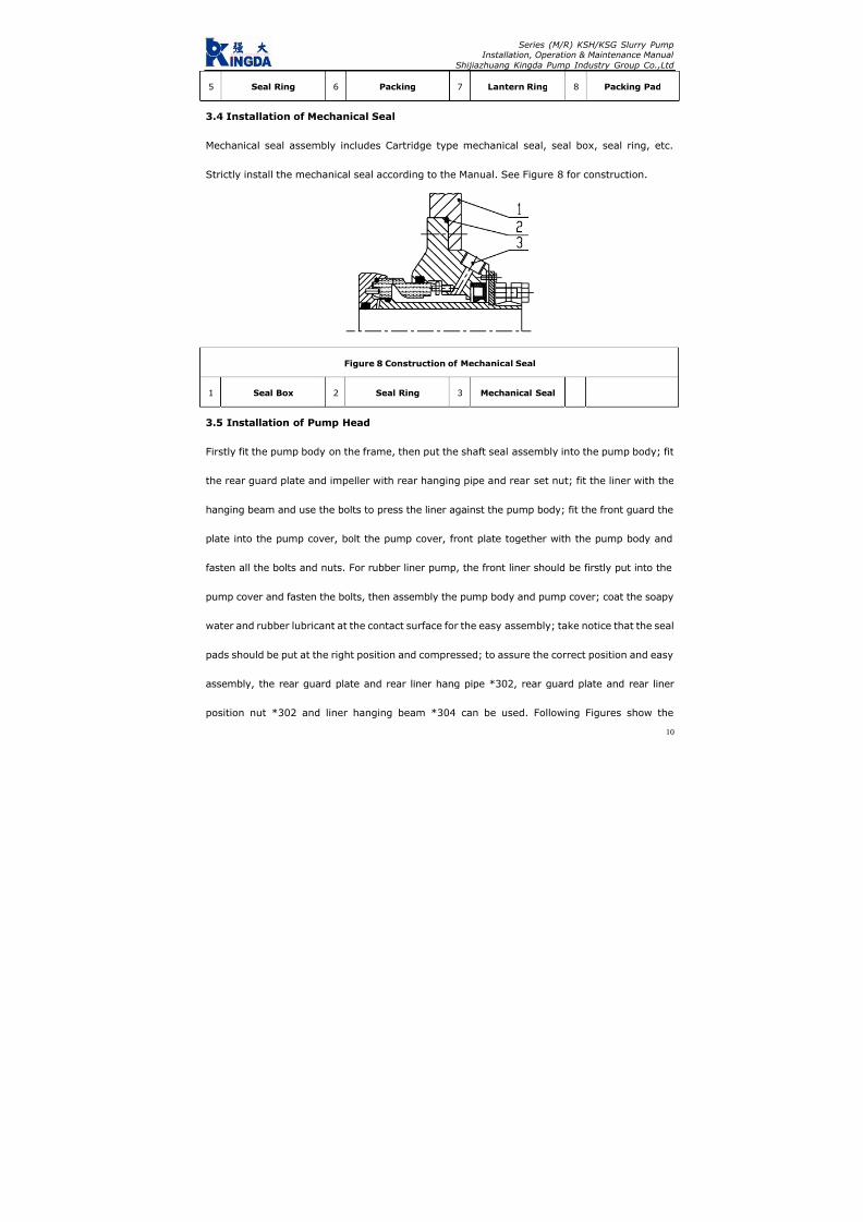
7/17/2019 R05323-P-001A-X009-0042.pdf
http://slidepdf.com/reader/full/r05323-p-001a-x009-0042pdf 179/463
Series (M/R) KSH/KSG Slurry PumpInstallation, Operation & Maintenance Manual
Shijiazhuang Kingda Pump Industry Group Co.,Ltd
5 Seal Ring 6 Packing 7 Lantern Ring 8 Packing Pad
3.4 Installation of Mechanical Seal
Mechanical seal assembly includes Cartridge type mechanical seal, seal box, seal ring, etc.
Strictly install the mechanical seal according to the Manual. See Figure 8 for construction.
Figure 8 Construction of Mechanical Seal
1 Seal Box 2 Seal Ring 3 Mechanical Seal
3.5 Installation of Pump Head
Firstly fit the pump body on the frame, then put the shaft seal assembly into the pump body; fit
the rear guard plate and impeller with rear hanging pipe and rear set nut; fit the liner with the
hanging beam and use the bolts to press the liner against the pump body; fit the front guard the
plate into the pump cover, bolt the pump cover, front plate together with the pump body and
fasten all the bolts and nuts. For rubber liner pump, the front liner should be firstly put into the
pump cover and fasten the bolts, then assembly the pump body and pump cover; coat the soapy
water and rubber lubricant at the contact surface for the easy assembly; take notice that the seal
pads should be put at the right position and compressed; to assure the correct position and easy
assembly, the rear guard plate and rear liner hang pipe *302, rear guard plate and rear liner
position nut *302 and liner hanging beam *304 can be used. Following Figures show the
10

7/17/2019 R05323-P-001A-X009-0042.pdf
http://slidepdf.com/reader/full/r05323-p-001a-x009-0042pdf 180/463
Series (M/R) KSH/KSG Slurry PumpInstallation, Operation & Maintenance Manual
Shijiazhuang Kingda Pump Industry Group Co.,Ltd
methods.
The pump with ST, T and TU has release ring; before dismantling, the three hex bolts should be
removed and screw them into thither bolt hole on the release ring to jack the three pressure pad
on the shaft to loose the impeller.
Figure 9
1. Rear Guard Plate and Rear Liner Hang Pipe x302
2. Rear Guard Plate and Rear Liner Setting Nut x303
3. Liner Hang Beam x304
11

7/17/2019 R05323-P-001A-X009-0042.pdf
http://slidepdf.com/reader/full/r05323-p-001a-x009-0042pdf 181/463
Series (M/R) KSH/KSG Slurry PumpInstallation, Operation & Maintenance Manual
Shijiazhuang Kingda Pump Industry Group Co.,Ltd
12
4 . OPERAT I ON
4.1 Startup
Check the whole machine unit as following procedure before start up:
(1): The pump should be installed on the solid base to bear the whole pump weight to absorb the
vibration and fasten all the foundation bolts.
(2): The pipeline and valves should be separately supported. There is seal pad at the pump flange.
Notice that the pump metal liner may be higher than flange surface when fastening the bolts, and
the bolts should be not over-fastened to avoid damaging the seal pad.
(3): Rotate the pump shaft in accordance with the pump rotation direction, the shaft should drive
the impeller without the friction; if not, the impeller clearance should be adjusted.
(4): Check the motor rotation direction to make sure it can drive the pump rotate toward the
arrow. Reverse rotation may cause the impeller screw stripped and damage the pump, so it’s
forbidden.
(5): For direct coupling drive, the pump shaft and motor shaft should be strictly centered. The
pump shaft and motor shaft should be in parallel for the belt transmission and adjust the pulley
position to make it vertical to the belt. For the pulley unit of SPA Type andSPA
SPB Type, SPB Type
andSPB
SPC Type, the adjustment of the pulley should reach the requirements of α1=α2 in Figure 10.
(6): A short removable pipe should be fit at the suction of the pump, its length is enough to
disassemble the pump cover, replace the wearing parts and inspect the pump. See the Outline
Dimensional Drawing for the length of this short pipe.
(7): Check shaft seal: for the pumps of expeller seal, when the oil cup is fit with the release gland,
the lubricating grease should be filled through the oil cup; and Sodium-calcium grease is

7/17/2019 R05323-P-001A-X009-0042.pdf
http://slidepdf.com/reader/full/r05323-p-001a-x009-0042pdf 182/463
Series (M/R) KSH/KSG Slurry PumpInstallation, Operation & Maintenance Manual
Shijiazhuang Kingda Pump Industry Group Co.,Ltd
recommended.
For the pumps of packing seal, firstly turn on the shaft sealing water system to check if the water
quantity and pressure is proper before the startup of the pump; adjust the packing gland set
screw to regulate the tension of the packing; adjust shaft seal water (that the leak quantity at the
packing gland is drop by drop); if too tight, the shaft sleeve will heat easily and power will be
consumed more; if too loose, the leak quantity will be very large. The shaft seal water pressure
usually is higher than pump discharge pressure by 3.5X10⁻²MPa (0.35kgf/cm2). See following
table for shaft seal water quantity:
Frame Type A B C D E.F G R.RS S.ST T.TU U
Shaft Seal Water Quantity (L/s) 0.15 0.25 0.35 0.55 0.70 1.2 0.70 1.2 1.6 2.1
(8) Adjustment for the Belt Pretightening Force
We recommend following method for reference:
(8.1) First calculate thee pretightening force Q:
Q=2
1
21 )5.2(510mv
V Z C
C PC +
××
×− (Newton)
(8.2) Then find the e value on the curve according to the pretightening force and belt type;
(8.3) Find f through formula f=e
.
L’
100 ;
(8.4) Find R value of respective V-belt in Table 1, and adjust the center distance of both pulleys
according to the methods in Figure 11 to reach the required pretightening force. Usually, if the
overall reduction is no more than f when loading the Newton force, it reaches the required
pretightening force Q.
In the formula:
Q: the minimum pretightening force of each belt in the static state, unit is Newton;
13

7/17/2019 R05323-P-001A-X009-0042.pdf
http://slidepdf.com/reader/full/r05323-p-001a-x009-0042pdf 183/463
Series (M/R) KSH/KSG Slurry PumpInstallation, Operation & Maintenance Manual
Shijiazhuang Kingda Pump Industry Group Co.,Ltd
f: Overall reduction of belt, unit is mm
C1: Angle coefficient is about 0.9
C2: Operation coefficient is about 1.4
L′: Center distance of pulleys
P: Motor Rated Power, KW
Z: V-Belt Quantity
V: linear velocity, m/s
m: Centrifugal force coefficient (see Figure 1)
e: Reduction e of each 100mm hang length, see Figure 11.
Table 1
Type SPA SPB SPC SPZ
R (N) 60 90 120 30
m 0.12 0.20 0.38 0.08
Adjust the V-belt till the final pretightening force is the minimum when the load is at max; when
several belts are used at the same time, the circumference of each belt should be basically the
same to assure the equal force.
Figure 10
14

7/17/2019 R05323-P-001A-X009-0042.pdf
http://slidepdf.com/reader/full/r05323-p-001a-x009-0042pdf 184/463
Series (M/R) KSH/KSG Slurry PumpInstallation, Operation & Maintenance Manual
Shijiazhuang Kingda Pump Industry Group Co.,Ltd
Figure 11
After adjustment of the V-belt, check if the impeller can rotate normally again; if possible, start
the pump with clear water (before it begins to pump the slurry); turn on the suction pipe valve,
start the motor, check the pressure and flow quantity at the suction and discharge, check the
leakage at the packing. If the packing heats, loose the packing gland bolts to make the leakage
bigger; adjust the leakage to the specified value till the packing run-in with the shaft.
4.2 Operation
(1): Periodically check the pressure and flow quantity of shaft seal water, and adjust the packing
gland and replace the packing during the operation to assure small quantity of clean water
passing through the shaft.
15

7/17/2019 R05323-P-001A-X009-0042.pdf
http://slidepdf.com/reader/full/r05323-p-001a-x009-0042pdf 185/463
Series (M/R) KSH/KSG Slurry PumpInstallation, Operation & Maintenance Manual
Shijiazhuang Kingda Pump Industry Group Co.,Ltd
16
(2): Periodically check the frame. If the bearing heats at the beginning of the operation, shut
down the pump till the bearing become cool, then run it. If the bearing heats seriously and
temperature keep rising, the frame must be disassembled and examined for the cause. Usually
the impurity contained in the lubricating oil can cause the heating, so the bearing oil should be
proper and clean, and replaced periodically.
(3): The pump performance will become poorer and the efficiency will become lower with the
larger and larger clearance between impeller and front guard plate. So adjust the impeller timely
to keep the proper clearance to make the pump run in high efficiency. When the wear situation of
the pump is too bad to meet the requirements of the system, the wear parts should be replaced.
4.3 Shutdown of Pump
Let the pump to transport the clear water for some before the shutdown to clean the slurry left
inside the pump, then stop the pump, valve, packing seal water or mechanical seal water in order.

7/17/2019 R05323-P-001A-X009-0042.pdf
http://slidepdf.com/reader/full/r05323-p-001a-x009-0042pdf 186/463
Series (M/R) KSH/KSG Slurry PumpInstallation, Operation & Maintenance Manual
Shijiazhuang Kingda Pump Industry Group Co.,Ltd
17
5 . MA I NTENAN CE
For the safe run of pump, attention must be paid to the normal maintenance as following aspects:
5.1 Maintenance of shaft seal:
For the packing seal pump, periodically check the water pressure and water quantity of shaft
packing seal. Always keep small quantity of clear water flow along with the shaft, periodically
adjust the packing gland, check and replace the packing. The shaft seal water pressure and
quantity should in accordance with the above requirements. Periodically fill the oil into the oil cup
for the expeller seal pump to lubricate the inside packing.
5.2 Adjustment of impeller:
To assure the high-efficiency of the pump, the clearance between the impeller and the front guard
plate; the clearance between impeller and front guard plate of metal liner pump should be
0.5-1mm, the clearance between the impeller and front liner should be equal to that between
impeller and rear liner.
Before adjusting the clearance, the pump should be stopped firstly, then loose the bolts of
bearing assembly and screw the nut of adjusting bolts to make the bearing assembly move
forward, at the same time, rotate the pump as per the arrow by hands till the impeller friction
with the front guard plate; for the metal liner pump, loose the nut (which was fastened) by half
circle, then fasten the nut on the adjusting bolt to make the bearing assembly move backward,
the clearance between the impeller and front guard plate should be 0.5-1mm; for the rubber liner
pump, adjust the nut of the adjusting bolts to make the bearing assembly to move forward to
contact with the front guard sleeve, then move the bearing assembly back to contact with the
back liner, and measure the total movement distance, make the half of this distance as the

7/17/2019 R05323-P-001A-X009-0042.pdf
http://slidepdf.com/reader/full/r05323-p-001a-x009-0042pdf 187/463
Series (M/R) KSH/KSG Slurry PumpInstallation, Operation & Maintenance Manual
Shijiazhuang Kingda Pump Industry Group Co.,Ltd
18
clearance of the impeller and front liner; assure the correct clearance of impeller and front and
back liner by adjusting bearing assembly position through the adjusting bolts.
After the adjustment, check if the impeller can rotate normally before startup, if bearing
assembly compress bolts and adjusting bolts are tightened; then start the pump.
5.3 Lubricating of Bearing
Correct assembly, proper lubricating and in-time maintenance will make the service life of
bearing assembly longer. Periodically check the bearing assembly, bearing and lubricant and
interval should not be over than 12 month. Fill the lubricating grease at regular intervals in
operation, the filling interval and filling quantity are relative to the pump speed, bearing size,
continuous operation time, shutdown and startup times, environmental condition and
temperatures; excess grease will cause the heating of bearing. Refer to following table for proper
lubricating schedule:
5.4 Standby pump should be rotated by 1/4 circle by hands to make the bearing stand static load
and vibration evenly

7/17/2019 R05323-P-001A-X009-0042.pdf
http://slidepdf.com/reader/full/r05323-p-001a-x009-0042pdf 188/463
Series (M/R) KSH/KSG Slurry PumpInstallation, Operation & Maintenance Manual
Shijiazhuang Kingda Pump Industry Group Co.,Ltd
Lubrication Schedule (in hours)
19
Note: Above Schedule is only applied for the normal working condition.
During the bearing assembly, the internal plug is to fill the bearing grease, and the external oil
cup is to clean the labyrinth seal. Besides the regular filling of grease, it’s also to fill the grease to
the oil cup to keep the labyrinth seal clean.
Bearing Speed (rpm)Frame
Type
Grease
Quantity 200 300 400 600 800 1000 1200 1800 2000
B 12 3000 2400 1800 1500 1000
C 18 3600 2400 1800 1600 1200 900
D 28 2500 2000 1500 1200 800 500
E 44 5000 3600 2200 1600 1100 800 500
F 71 7000 4200 2000 1800 1200 700 400
R.RS 102 3000 2000 1400 1000 600 400 100
S.ST 132 3800 28000 1500 900 500 300
T.TU 304 4800 3000 1800 900 400
Pump
End
U 621 4000 2400 1500 500
R.RS 61 8000 4800 3500 2800 2200 1500 900
S.ST 74 8000 6000 3600 2400 1600 1200
T.TU 133 8000 7000 4500 2500 1500
Motor
End
U 192 7000 6000 4000 2000
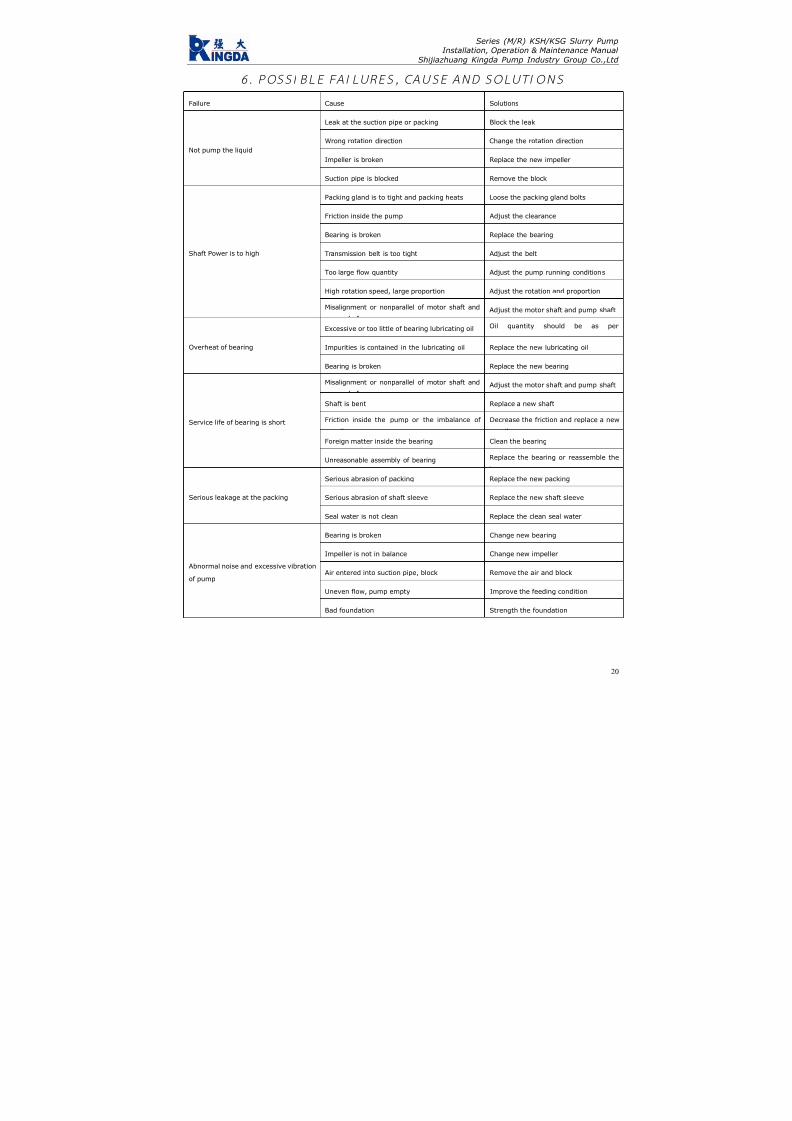
7/17/2019 R05323-P-001A-X009-0042.pdf
http://slidepdf.com/reader/full/r05323-p-001a-x009-0042pdf 189/463
Series (M/R) KSH/KSG Slurry PumpInstallation, Operation & Maintenance Manual
Shijiazhuang Kingda Pump Industry Group Co.,Ltd
20
6 . POSS I B LE FA I LURES , CAUSE AN D SOLUT I ONS
Failure Cause Solutions
Leak at the suction pipe or packing Block the leak
Wrong rotation direction Change the rotation direction
Impeller is broken Replace the new impeller
Not pump the liquid
Suction pipe is blocked Remove the block
Packing gland is to tight and packing heats Loose the packing gland bolts
Friction inside the pump Adjust the clearance
Bearing is broken Replace the bearing
Transmission belt is too tight Adjust the belt
Too large flow quantity Adjust the pump running conditions
High rotation speed, large proportion Adjust the rotation and proportion
Shaft Power is to high
Misalignment or nonparallel of motor shaft and Adjust the motor shaft and pump shaft
Excessive or too little of bearing lubricating oil Oil quantity should be as per
Impurities is contained in the lubricating oil Replace the new lubricating oilOverheat of bearing
Bearing is broken Replace the new bearing
Misalignment or nonparallel of motor shaft and Adjust the motor shaft and pump shaft
Shaft is bent Replace a new shaft
Friction inside the pump or the imbalance of Decrease the friction and replace a new
Foreign matter inside the bearing Clean the bearing
Service life of bearing is short
Unreasonable assembly of bearing Replace the bearing or reassemble the
Serious abrasion of packing Replace the new packing
Serious abrasion of shaft sleeve Replace the new shaft sleeveSerious leakage at the packing
Seal water is not clean Replace the clean seal water
Bearing is broken Change new bearing
Impeller is not in balance Change new impeller
Air entered into suction pipe, block Remove the air and block
Uneven flow, pump empty Improve the feeding condition
Abnormal noise and excessive vibration
of pump
Bad foundation Strength the foundation

7/17/2019 R05323-P-001A-X009-0042.pdf
http://slidepdf.com/reader/full/r05323-p-001a-x009-0042pdf 190/463
INSTALLATION,OPERATION ANDMAINTENANCE
INSTRUCTION MANUALFOR INDUCTION
MOTORSFrame sizes 143/5T to 586/7
WEG EXPORTADORA S.A.
Av. Prefeito Waldemar Grubba, 300089256-900 - J aragua do Sul - SC - BRAZIL
Phone 55 (47) 3372-4000 - Fax 55 (47) 3372-4060http://www.weg.com.br
Transforming Energy into Solutions
0 2 8 0 . 1
5 1 5 / 0 3 . 2
0 0 6

7/17/2019 R05323-P-001A-X009-0042.pdf
http://slidepdf.com/reader/full/r05323-p-001a-x009-0042pdf 191/463
THIS MANUAL IS INTENDED TO SUPPLY IMPORTANT TOPICS THAT MUST BE FOLLOWED DURING
TRANSPORTATION, INSTALLATION, OPERATION AND MAINTENANCE OF WEG MOTORS. THEREFORE, WE RECOMMEND READING CAREFULLY THIS MANUALBEFORE INSTALLING AND OPERATING THE MOTOR.
TO ENSURE PHYSICAL INTEGRITY TO THE OPERATION AND MATERIAL PROTECTION, ALL
INFORMATION INCLUDED IN THIS MANUAL MUST BE STRICTLY FOLLOWED.
I
INDEX
1. HANDLI NG AND TRANSPORTATION 2. RECEIVING INSPECTION 3. STORAGE 4. INSTALLATION
4.1 - Safe ty 4.2 - Op e ra ti ng Co n di ti o ns 4.3 - Fo u nd a ti on 4.4 - D ra in H o le s 4.5 - B alan ce 4.6 - Al ig nm e nt 4.7 - C ou p li ng s 4.8 - El ec t r ic a l Co n ne c t io n 4.9 - St ar ti ng Me th o ds 4 .10 - P ro tec t i on Dev i ce
4.11 - Star t -Up 5. MAINTENANCE
5.1 - Lubrication 5.1 .1 - Mach ines wi thout Grease Nipp les 5.1.2 - Mac hines Fitted with G rease Fitting 5.1.3 - Com patibil ity of MOBIL Polirex EM
grease with other types of grease 5 .2 - A ssemb ly and D i s as semb l y
6. SPARE PARTS 7. VARIABLE FREQUENCY DRIVE MOTORS
7.1 - St an d ar d Mo t or s 7 .2 - I nv er te r Du t y Mo to r s 7 .3 - Bear in g I n su l at io n
8. ADDITIONAL INSTRUCTIONS 8 .1 - Haza rd ou s Ar ea Mo to r s
8.1 .1 - Gene ra l 8.1.2 - Instal lat ion 8.1 .3 - Chec k ing and main tenanc e 8.1.4 - Explosion Proof M otor Repairs
9. WARRANTY TERMS
Purchasing date:
Supplier’s name
Invoice/Order number:
Customer’s name and phone:
Failure description:
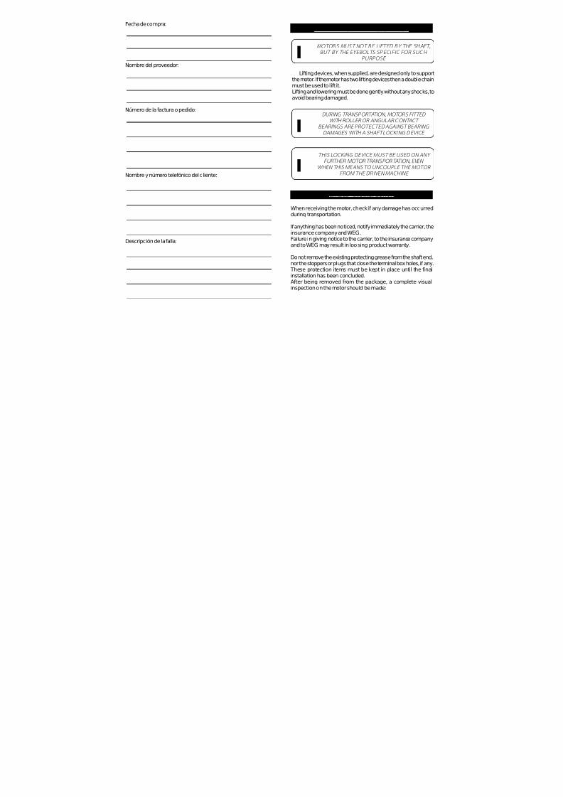
7/17/2019 R05323-P-001A-X009-0042.pdf
http://slidepdf.com/reader/full/r05323-p-001a-x009-0042pdf 192/463
Lifting devices, when supplied, are designed only to supportthe motor. If the motor has two lifting devices then a double chainmust be used to lift it.Lifting and lowering must be done gently without any shocks, toavoid bearing damaged.
DURING TRANSPORTATION, MOTORS FITTED WITH ROLLER OR ANGULAR CONTACT
BEARINGS ARE PROTECTED AGAINST BEARING DAMAGES WITH A SHAFT LOCKING DEVICE
MOTORS MUST NOT BE LIFTED BY THE SHAFT,
BUT BY THE EYEBOLTS SPECIFIC FOR SUCH
PURPOSE
THIS LOCKING DEVICE MUST BE USED ON ANY FURTHER MOTOR TRANSPORTATION, EVEN
WHEN THIS MEANS TO UNCOUPLE THE MOTOR FROM THE DRIVEN MACHINE
I
I
I
2. RECEIVING INSPECTION
When receiving the motor, check if any damage has occurredduring transportation.
If anything has been noticed, notify immediately the carrier, theinsurance company and WEG.Failure in giving notice to the carrier, to the insurance companyand to WEG may result in loosing product warranty.
Do not remove the existing protecting grease from the shaft end,nor the stoppers or plugs that close the terminal box holes, if any.
These protection items must be kept in place until the finalinstallation has been concluded.After being removed from the package, a complete visualinspection on the motor should be made:
1 - HANDLING AND TRANSPORTATIONFecha de compra:
Nombre del proveedor:
Número de la factura o pedido:
Nombre y número telefónico del cliente:
Descripción de la falla:

7/17/2019 R05323-P-001A-X009-0042.pdf
http://slidepdf.com/reader/full/r05323-p-001a-x009-0042pdf 193/463
If motors are not immediately installed, they must be stored indry areas, free of dust, vibrations, gases, corrosive smokes, underconstant temperature and in normal position free from othermaterials.
Motor storage temperature must remain between 41ºF (5ºC) to140ºF (60ºC), with relative humidity not exceeding 50%.
If motors are stored for more than two years, bearings must bereplaced or the lubrication grease must be totally removed aftercleaning.
Single-phase motors when kept in stock for 2 years or moremust have their capacitors replaced (if any).
WEG recommends to rotate the shaft (by hands) at least once a
month, and to measure the insulation resistance before installingit, if motors are stored for more than 6 months or when subjectto high humidity areas.
If motor is fitted with space heaters, it is recommended to switchthem on during storage period if the relative humidity exceeds50%.If motor remains in stock for a long period without having thespace heaters switched-on or when installed but not in operation,moisture/water inside the motor may condense. On these cases,water must be drained by removing the threaded drain plugs.When drainage is done, switch-on the space heaters and makesure the motor is completely dry, then reinstall the drain plugs toensure proper Degree of Protection (see figure 1).
The space heaters should NEVER be energized while motor isrunning.
3 - STORAGE
ü Check if any damage has occured during transportation.ü Check nameplate data.ü Rotate shaft with the hand to make sure it is running freely.ü Make sure the motor was not exposed to excessive dirt andmoisture during transportation and storage.
9. TERMINOS DE GARANTIA
WEG of rec e garantía co nt ra defec tos d e fabr icac ión o d e materiales para sus p roduc tos, por un p eríodo de 18 me ses,con tados a partir de la fecha de la emisión de la factura por parte de fáb rica o d el distribuidor/revendedor, teniendo c omo límite 24 meses d e la fecha de fabric ación indep endiente de la fecha de instalac ión del motor, siemp re y cuand o hayan sido sat isfechos los siguientes requis i tos:
- Transpor te , manoseo y a lmacenamiento adecuados; - I n s t a la c i ón co r r e c t a y en cond i c i o ne s amb i e n t a l e s espec íficas y sin presenc ia de g a ses corrosivos; - Operación dentro de los límites de la capacid ad del moto r; - Realización periódica del d ebido m antenimiento prevent ivo; - Realización de reparaciones y/o modif icaciones al producto original efectuada solo por los agentes autorizados de la Red de Asiste nc ia Técn ic a WEG; - Entregar el producto a l proveedor en el caso de ocurr i r una fal la c on rec lam aci ón d e g arant ía en un p eríod o m ínim o su f i c i en te p a ra iden t i f i ca r la causa d e la an oma lía y su conven ien te repa rac ión ; - Dar av iso inmed ia to a WEG, por par te de l c l ien te , de los defectos detec tados y que los mismos sean poster iormente ana l i za do s po r WEG co mo c au sado s po r de f e c t o s de fabr icac ión.La garant ía no inc luye los servicios de desmo ntaje d el moto r en las ins ta lac iones de l c l ien te , cos to s de t ranspor te de l produc to y gastos de traslado, alojamiento y alimentación del person al de Asistencia Técnic a cuand o sean solic itados p or e l c l ien te .Los ser vicio s en ga rantía serán pre stad os exc lusivam ente e n talleres d e Asistenc ia Técn ica Aut orizada WEG o en la prop ia fábric a.Se excluyen de esta gara ntía los c ompon entes c uya vida útil,en u so no rmal, sea inferior a l períod o d e ga rantía ot orga do po r WEG las repa rac ion es o subs t i t u c iones de p iezas o pro duc t os , a cr i te r io de WEG o su Asis ten c ia Técn ica Autori zada, no pro rrog ará el plazo de g arantía orig inal.La presente g arantía se limita al pro duc to entreg ado, no sien do respon sable WEG po r daños a person as, a terc eros, a o tros
equipos e instalaciones, ut i l idades que se dejen de ob tener o cu alquier otro daño eme rgente o c onsec uente.
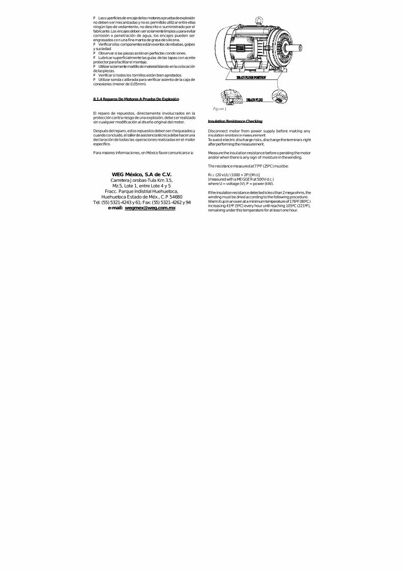
7/17/2019 R05323-P-001A-X009-0042.pdf
http://slidepdf.com/reader/full/r05323-p-001a-x009-0042pdf 194/463
Insulation Resistance Checking
Disconnect motor from power supply before making anyinsulation resistance measurement.
To avoid electric discharge risks, discharge the terminals rightafter performing the measurement.
Measure the insulation resistance before operating the motorand/or when there is any sign of moisture in the winding.
The resistance measured at 77ºF (25ºC) must be:
Ri ≥
(20 x U) / (1000 + 2P) [MΩ](measured with a MEGGER at 500 V d.c.)where U = voltage (V); P = power (kW).
If the insulation resistance detected is less than 2 mega ohms, thewinding must be dried according to the following procedure:Warm it up in an oven at a minimum temperature of 176ºF (80ºC)increasing 41ºF (5ºC) every hour until reaching 105ºC (221ºF),remaining under this temperature for at least one hour.
Figure 1
P Las superficies de encaje de los motores a prueba de explosiónno deben ser mecanizadas y no es permitido utilizar entre ellasningún tipo de vedamiento, no descrito o suministrado por elfabricante. Los encajes deben ser solamente limpios y para evitarcorrosión o penetración de agua, los encajes pueden serengrasados con una fina manta de grasa de silicona.P Verificar si los componentes están exentos de rebabas, golpesy suciedad.P Observar si las piezas están en perfectas condiciones.P Lubricar superficialmente las guías de las tapas con aceiteprotector para facilitar el montaje.P Utilizar solamente martillo de material blando en la colocaciónde las piezas.P Verificar si todos los tornillos están bien apretados.P Utilizar sonda calibrada para verificar asiento de la caja deconexiones (menor de 0,05mm).
8.1.4 Reparos De Motores A Prueba De Explosión
El reparo de repuestos, directamente involucrados en laprotección contra riesgo de una explosión, debe ser realizadosin cualquier modificación al diseño original del motor.
Después del reparo, estos repuestos deben ser chequeados ycuando concluido, el taller de asistencia técnica debe hacer unadeclaración de todas las operaciones realizadas en el motorespecífico.
Para maiores informaciones, en México favor comunicarse a:
WEG México, S.A de C.V.Carretera J orobas-Tula Km 3.5,Mz.5, Lote 1, entre Lote 4 y 5
Fracc. Parque Indistrial Huehuetoca,Huehuetoca Estado de Méx., C.P 54680 Tel: (55) 5321-4243 y 61; Fax: (55) 5321-4262 y 94
e-mail: [email protected]

7/17/2019 R05323-P-001A-X009-0042.pdf
http://slidepdf.com/reader/full/r05323-p-001a-x009-0042pdf 195/463
Check if the stator insulation resistance remains constant withinaccepted values. If not, stator must be reimpregnated. If necessary,replace bearings and seals.
Note:
1) All drains (if any) must be removed while drying.2 - Measured the insulation resistance in ambient temperature. If different than 25ºC it should be corrected using the followingformula:
R(25°C) = [( K+25 ) / ( K + Ta )] . R (Ta)
Where:R
(25°C)insulation resistance related to 25ºC ambient temperature
K constant value 234.5 for copper T
aambient temperature where the resistance was measured
R(Ta)
resistance value measured in ambient temperature Ta
4. INSTALLATION
4.1 - Safety
All personnel involved with electrical installations, eitherhandling, lifting, operation, start up, maintenance or repair must
be well informed and updated concerning safety standards andprinciples that govern the work and carefully follow them.
For practical reasons, it is not possible to include in this Manualdetailed information that covers all constructive variables, norcovering all possible assembly, operation or maintenancealternatives.For this reason, the present Manual only includes requiredinformation that allows qualified and trained personnel to carryout the work.
If you still have further doubts about this, specially in referenceto specific product information, WEG is willing to provide suchinformation via its network of authorized service agents and/ordistributors.
In order to allow WEG to provide prompt service, within technicalstandards, the motor serial number that is available on theidentification nameplate should be supplied.
Use always appropriate tools for installation and removal.
LA INSTALACION DE MOTORES PARA AMBIENTES PELIGROSOS DEBE SER EJECUTADA POR
PERSONAL ESPECIALIZADO
LA ESPECIFICACION DEL LOCAL DE INSTALACION ES DE RESPONSABILIDAD DELCLIENTE, QUE TAMBIEN DETERMINARA LAS
CARACTERISTICAS AMBIENTALES
Cuando se utiliza el prensa cables en la entrada de los cables, lomismo debe ser apropiado para el motor y para el tipo de terminal,el prensa cables debe ser montado, completamente apretado demanera a adquirir la presión necesaria arriba de los anillos devedamiento, bien como:ü Evitar la transmisión de vibraciones mecánicas para losterminales del motor.ü Garantizar la protección mecánica “IP” para la caja deconexiones.
8.1.3 Chequeo y Mantenimiento
El mantenimiento debe ser ejecutado por talleres técnicosautorizados y acreditados por WEG.
Talleres y personal sin autorización que realicen reparación enlos motores para ambientes peligrosos, serán totalmenteresponsables por el trabajo ejecutado y los daños ocurridos ensu servicio.
En la ejecución del mantenimiento, instalación y relubricación, sedeben seguir las siguientes orientaciones:
ü Las conexiones deben estar correctamente cerradas para evitarelevación de resistencia, consecuentemente sobrecalentamientodel contactoü Aislamiento distancia-aire y distancia-superficie entre losconductores, requeridos por las normas, deben ser respectados
ü
Todos tornillos utilizados en el montaje de las partes del motory caja de conexión, deben ser completamente apretadosü Vedamientos y repuestos para entrada de los cables seránhechos utilizando materiales suministrados por el fabricante, demanera a garantizar el tipo de protección original
I
I

7/17/2019 R05323-P-001A-X009-0042.pdf
http://slidepdf.com/reader/full/r05323-p-001a-x009-0042pdf 196/463
MAKE SURE THAT ELECTRIC MOTORS ARE SWITCHED OFF BEFORE STARTING ANY MAINTENANCE SERVICE I
All rotating parts such as pulleys, couplings, outside fans, shaft,etc. must be protected against accidental contact.Motors must be protected against unexpected starts.When performing any maintenance service, disconnect the motorfrom the power supply. Make sure all accessories have been
switched off and disconnected.In order to prevent from penetrating dust and/or water into theterminal box, cable glands or threaded pipe in the lead holespassage must be installed. They must be of equal or higher IPrating than the motor.
LEAD CONNECTION INSULATION INSIDE THE TERMINAL BO X MUST BE DONE WITH AN INSULATING
MATERIAL COMPATIBLE WITH MOTOR THERMALCLASS WHICH IS SHOWN ON THE MOTOR
NAMEPLATE
I
If installation and safety instructions are not followed accordingly,warranty may be void.
4.2 - Operating Conditions
In general electric motors are designed for operation up to analtitude of 1000m above sea level for an ambient temperatureranging from -4ºF (-20ºC) to 104ºF (40ºC). Any variation is statedon the nameplate.
The recommended installation distance between air inlet fromthe motor and the wall should be at least ¼ of the air inlet diameter.A person should have enough room to carry out cleaning services.Machines that are cooled with ambient air, air inlet screens mustbe cleaned at regular intervals so as to ensure free air circulation.Warm air can not return to the motor.ü For vertically mounted motors with air inlet on top, the air
opening must be protected by a proper cover so as to avoiddropping of foreign materials on the motors.ü Considering that direct sun heat causes increase intemperature, externally installed motors should be alwaysprotected against weathering.
7.3– Aislamiento del rodamiento
Los motores Inverter Duty en las carcasas 504/5T y 586/7T* sonsuministrados con sistema de puesta a tierra entre el eje y la carcasaen el lado delantero. También, bajo pedido puede ser suministradocon rodamientos aislados.
Para otras líneas, en las carcasas 504/5T y 586/7T* cuando usadoscon convertidor de frecuencia es necesario sistema de puesta atierra entre el eje y la carcasa o rodamientos aislados.
* Otros tamaños de carcasas, bajo consulta.
8 – INSTRUCCIONES ADICIONALES
8.1 – Motores Para Areas de Riesgo
8.1.1 General
Además de las recomendaciones arriba, las siguientes tambiéndeben ser observadas:
Motores para áreas de riesgo son fabricados de acuerdo connormas específicas para estos ambientes.Motores suministrados para áreas de riesgo (áreas clasificadas)deben ser instalados en área que estén de acuerdo con lasespecificadas en la tarjeta de identificación del motor.
Notas:
ü Motores División I son también adecuados para la División IIü Motores de una especificada clase de temperatura son tambiénadecuados para ambientes con combustible de una clase detemperatura mayor (ejemplo, motores T4 son adecuados paraambientes de clase T3, T2, T1).
8.1.2 Instalación
La instalación debe seguir procedimientos elaborados por lalegislación local vigente.

7/17/2019 R05323-P-001A-X009-0042.pdf
http://slidepdf.com/reader/full/r05323-p-001a-x009-0042pdf 197/463
COMPARE THE CURRENT, VOLTAGE, FREQUENCY,SPEED, OUTPUT AND OTHER VALUES REQUIRED BY
THE APPLIC ATION WITH MOTOR NAMEPLATE INFORMATION
I
ODP MOTORS – Open motors (IP21, IP23) are machines designedfor operation in clean, dry areas, with enough air circulation forproper cooling. These motors should never be used in areas withflammable materials. Open motors may cause sparks and releasecast particles under any eventual insulation failure (short-circuit).
TEFC MOTORS – Totally enclosed motors are machines suitable tooperate in areas with moisture, dirt and/or corrosive materials eitherin enclosed or open environments.
4.3 - Foundation
Motors provided with feet must be installed on solid foundationsto avoid excessive vibrations.All motors must be fully fixed and aligned.
The purchaser is fully responsible for the foundation.Metal parts must be painted to avoid corrosion.
The foundation must be uniform and sufficiently strong to supportany shock. It must be designed in such a way to stop any vibration
originated from resonance.
Note: Considering that rotation direction is important for correctoperation, then check it carefully before connecting motor to theload.
4.4 - Drain Holes
Make sure drains are placed at the lower motor position when themounting configuration differs from that specified on the motorpurchase order.
4.5 – Balance
WHEN SPECIAL BALANCE IS REQUIRED,CONTACT THE FACTORY I
EL NO CUMPLIM IENTO DE ESTAS RECOMENDACIONES Y CRITERIOS CAUSA LA
PERDIDA DE GARANTIA DEL MOTOR
7.2 – Motores Inverter Duty
Motores con tensiones superiores a 575V e igual o menor que690V y alimentados por convertidor de frecuencia no necesitanfiltros caso sigan las especificaciones abajo:
I
( * ) I n f o r m a
d o p o r e
l f a b r i c a n
t e d e
l c o n v e r t i d o r .
ü Observar tensión dealimentación del conjuntoventilación forzada.
EL NO CUMPLIMIENTO DE ESTAS
RECOMENDACIONES Y CRITERIOS CAUSA LAPERDIDA DE GARANTIA
DEL MOTOR
I

7/17/2019 R05323-P-001A-X009-0042.pdf
http://slidepdf.com/reader/full/r05323-p-001a-x009-0042pdf 198/463
All motors are dynamically balanced at the factory with half key.
Transmission elements such as pulleys, couplings etc must bedynamically balanced with half key before installation.
Always use appropriate tools for installation and removal.
4.6 – Alignment
ALIGN THE SHAFT ENDS AND USE FLEXIBLE COUPLING, WHENEVER POSSIBLE I
Make sure that the motor mounting devices do not allowmodifications on the alignment and further damages to thebearings.When assembling a half-coupling, make sure to use suitableequipment and tools to protect the bearings.Suitable assembly of half-coupling:Specially in cases of direct couplings, motor shaft must bealigned axially and radially with the driven machine shaft.
Incorrect alignment can lead to bearing damage, vibrations oreven cause shaft rupture.
Correct alignment can be ensured with the use of dial gauges,as shown in figures 4.6.1, 4.6.2 and 4.6.3.
If considering a complete shaft turn, misalignment should notexceed 0.05 mm.
Fig. 4.6.1 - Axial reading (p arallelism )
Favor informar también el número de serie del motor de latarjeta de identificación.
7 – MOTORES PARA USO CON CONVERTIDOR DE FRECUENCIA
7.1 – Línea de motores Standard
Motores con tensiones hasta 575V y accionados porConvertidor de Frecuencia no requieren filtros cuandoadoptados los criterios a seguir:
( * ) I n f o r m a
d o p o r e
l f a b r i c a n
t e d e
l c o n v e r t i d o r .
Notas:
1) Trajeta deidentificaciónmostrando tensión380-415V / 660-690V -50Hz y 440-460V - 60Hzy alimentados porconvertidor en tensión660-690V - 50Hz o 480V- 60Hz requiere el usode filtros.2) Motores en lascarcasas 504/5T y 586/
7T* cuando usadoscon convertidor,necesitan uso derodamientos aislados.
* Otros tamaños decarcasas, bajo consulta.

7/17/2019 R05323-P-001A-X009-0042.pdf
http://slidepdf.com/reader/full/r05323-p-001a-x009-0042pdf 199/463
Fig. 4.6.2 – Radial read ing (c onc entric ity)
Fig. 4.6.3 – Axial and radial readin g c ombined
The axial alignment (“E” dimension) between half couplingsshould be performed in accordance with manufacturer’srecommendations.
If required, WEG can offer its personnel duly trained as well as alaser equipment to make motor and driven machine alignment/
leveling.
Expansion effect of the components may change the alignment/leveling conditions during performance.
Notas:
ü Aunque la grasa Polyrex® EM (Mobil) sea compatible conlos tipos de grasa mencionados arriba, no recomendamos lamezcla con cualquier tipo de grasa.ü Si Ud. necesita utilizar otro tipo de grasa diferente de lasrecomendadas arriba, primeramente contacte con WEG.
LA UTILIZACION DE MOTORES NORMALES EN LOCALES Y/O APLICACIONES ESPECIALES DEBE
ESTAR PRECEDIDA DE UNA CONSULTA ALFABRICANTE DE GRASAS Y/O A WEG
I
5.2 - Desmontaje Y Montaje
ü El desmontaje y montaje del motor deberá ser hecho por
personal calificado, utilizando solamente herramientas ymétodos adecuados.ü Las garras del extractor de rodamientos deberán estar
aplicadas sobre la pista interna o sobre la tapa interior.ü Es esencial que el montaje de los rodamientos sea ejecutadoen condiciones de rigurosa limpieza, para asegurar un buenfuncionamiento y evitar daños. En el caso de colocarrodamientos nuevos, éstos deberán ser retirados de su embalajesolamente en el momento previo de su montaje al motor.ü Antes de instalar un rodamiento nuevo, es necesario verificarsi el alojamiento del mismo en el eje se encuentra exento derebabas o señales de golpes.ü Para montaje del rodamiento caliente sus partes internas conequipamiento apropiado – por inducción – o utilice herramientasapropiadas.
6. PARTES Y PIEZAS (REPUESTOS)
Al solicitar piezas para reposición, es conveniente indicar ladesignación completa del motor, así como el código del mismoque aparece marcado en la tarjeta de identificación.

7/17/2019 R05323-P-001A-X009-0042.pdf
http://slidepdf.com/reader/full/r05323-p-001a-x009-0042pdf 200/463
4.7 – Couplings
When using pulley or belt drive (coupling), follow theinstruction given below:
Remove shaft-locking device (if any) before installing the motor.
Belts must be tighten just enough to avoid slippage whenrunning, according to the specifications stated on the beltsupplier recommendation.
To make the installation of the pulley on the shaft easier, it isrecommended to heat up the pulley at 176ºF (80°C) and haveit mounted at hot, using suitable tools.
To avoid bearing and shaft end damage, mounting anddismounting of pulleys must be made with suitable tools.
While mounting and dismounting a pulley, never make pressureor knocks on the bearings.
Always use flexible couplings; rigid couplings require specialbearing arrangement as well as axial and radial alignment of the shafts.
WARNING: EXCESSIVE BELT/CHAIN TENSION WILL DAMAGE
THE BEARINGS AND LEAD TO A PROBABLE SHAFT RUPTURE
The couplings used must be suitable to withstand radial andaxial vibrations during operation. Special care must be taken toavoid that the allowable load and speed limits given in the catalogare not exceeded.
4.8 – Electrical Connection
Make sure the motor is connected to the correct power supply.
The cable gauges and the protection devices must be designedbased on motor rated current.
AVISO:
Las tablas arriba son recomendadas específicamente pararelubricación con grasa Polyrex® EM (Mobil) y temperaturasabsolutas de operación del rodamiento de:ü 70ºC (158ºF) para motores carcasas 254/6T hasta 324/6T.ü 85ºC (185ºF) para motores carcasas 364/5T hasta 586/7T.
Para cada 15ºC (59ºF) arriba de ese límite, los intervalos delubricación deben ser reducidos a la mitad. Los rodamientossellados (ZZ) son lubricados para una determinada vida útil,
una vez operando bajo condiciones de temperatura de 70ºC(158ºF).
ü Los periodos de relubricación informados arriba son paralos casos de aplicación con grasa Polyrex EM (Mobil)ü Motores montados de forma vertical deben tener su intervalode relubricación reducido a la mitad cuando comparados conmotores en la posición horizontal.ü Para aplicaciones con altas o bajas temperaturas, variaciónde velocidad, etc. el tipo de grasa e intervalos de relubricaciónson informados en una tarjeta de identificación adicional fijadaal motor.
RECOMENDAMOS EL USO DE RODAMIENTOS
DE ESFERAS PARA MOTORES ACOPLADOS DIRECTAMENTE A LA CARGA
PELIGRO: GRASA EN EXCESO PUEDE PROVOCAR
SOBRECALENTAMIENTO DE LOS RODAMIENTOS,RESULTANDO UN DAÑO TOTAL
5.1.3 – Compatibilidad de la grasa Polirex EM (Mobil) con
otros tipos de grasa:
Conteniendo espesante polyurea y aceite mineral, la grasaPolyrex® EM (Mobil) es compatible con otros tipos de grasa lascuales contengan:ü Base de litio o complejo de litio o polyurea y aceite mineralaltamente refinado.ü Aditivo inhibidor contra corrosión, herrumbre y aditivosantioxidantes.
I
I

7/17/2019 R05323-P-001A-X009-0042.pdf
http://slidepdf.com/reader/full/r05323-p-001a-x009-0042pdf 201/463
Voltage may be con nected at mo tor standstill inside the terminal box for heating elements
or direct winding heating
The capacitor on single-phase motors can retain a charge which app ears across the moto r terminals, even when the moto r has
reached standstill co ndition. So, avoid touching them at such c ondition
A WRONG CONNECTION CAN BURN OUT THE MOTOR.I
Voltage and connection are indicated on the motor nameplate. The acceptable voltage variation is ±10%;the acceptable frequency variation is +3% and -5% and thetotal acceptable variation for voltage and frequency is ± 10%.Note: For rated voltage range (Tru Metric Line), the acceptablevariation is ± 5% according to IEC 60034-1.
4.9 - Starting Methods
The motor is rather started through direct starting. In case thisis not possible, use compatible start methods to the motor loadand voltage.When applying reduced voltage-starting method, rememberthat the starting torque will also reduce.
P 3 leads single voltage and 9 leads dual voltage motors can bestarted as follows:- Full Voltage Direct online- Auto-Transformer starting- Electronic Soft-Starting- VFD Starting – subject to verification and application analisys.
- Series - Parallel starting (only for 9 leads)
P 6 leads single and dual voltage motors and 12 leads dualvoltage motors can be connected as follows:- Full Voltage Direct online
La frecuencia adecuada para realizar las inspecciones dependerádel tipo de motor y de las condiciones de aplicación.
PARA LUBRICACION, USE EXCLUSIVAMENTEPISTOLA ENGRASADORA MANUALI
I N T E R V A L O S D E R E L U B R I C A C
I O N –
G R A S A P O L I R E X E M
( M O B I L )
~
WARNING
~
WARNING
7/17/2019 R05323-P-001A-X009-0042.pdf
http://slidepdf.com/reader/full/r05323-p-001a-x009-0042pdf 202/463
- WYE/DELTA starting- Auto-Transformer starting- Electronic Soft-Starting- VFD Starting – subject to verification and application analisys.- Series - Parallel starting (only for 12 leads)
Rotation direction is clockwise when motor is viewed fromDrive Endshields side and if the phases are connectedaccording to sequence L1, L2, L3. This sequence and powersystem must be positive.
To change the rotation direction, reverse two of the connectingleads.Note: For single-phase motors connections, please check themotor nameplate.
THE CONNECTION TO THE POWER SUPPLY MUST BE DONE BY QUALIFIED PERSONNEL AND WITH FULL ATTENTION TO ASSURE SAFE AND
PERMANENT CONNECTION. AFTER CONNECTING THE MOTOR, CHECK FOR ANY
STRANGE BODY INSIDE THE TERMINAL BOX. THE CABLE INLETS NOT IN USE MUST BE CLOSED
I
Make sure to use correct cable gauge, based on the rated
current stamped on the motor nameplate.
BEFORE ENERGIZING THE TERMINALS, CHECK IF THE GROUNDING IS MADE ACCORDING TO THE APPLICABLE STANDARDS. THIS IS ESSENTIAL TO
AVOID ACCIDENTS
4.10 – Protection Device
When the motor is supplied with protective or monitortemperature device such as thermostats, thermistors, thermalprotector etc, connect their terminals to the correspondingdevices on the control panel. If this procedure is not followed
accordingly, warranty will be void.Do not change protection devices settings as they may notoperate.
I
NO REUTILIZAR PIEZAS DAÑADAS O CON DESGASTE.
SUBSTITUIR POR NUEVAS, ORIGINALES DE FABRICA
La frecuencia adecuada para realizar las inspeccionesdependerá del tipo de motor y de las condiciones deaplicación.
5.1 – Lubricación
I
PROCEDER DE ACUERDO CON LOS INTERVALOS DE REENGRASE RECOMENDADOS. ESTO ES VITAL
PARA LA OPERACION DEL MOTOR I5.1.1 - Motores sin grasera
Los motores hasta la carcasa 215T normalmente no llevan grasera.En estos casos el reengrase deberá ser efectuado conforme alplan de mantenimiento preventivo existente, teniendo en cuentalos siguientes aspectos:
P Desarmar cuidadosamente los motores.P Retirar toda la grasa.P Lavar los rodamientos con querosina o gasolina.P Secar los rodamientosP Reengrasar el rodamiento inmediatamente.
5.1.2 - Motores con grasera
Se recomienda efectuar el reengrase durante el funcionamientodel motor, de modo que permita la renovación de la grasa en elalojamiento del rodamiento. Si esto no fuera posible debido a lapresencia de piezas giratorias cerca de la entrada de grasa (poleas,acoplamientos, etc.) que puedan poner en riesgo la integridadfísica del operador, se procede de la siguiente manera:
P Limpiar las proximidades del agujero de la grasera.P Inyectar aproximadamente la mitad de la cantidad total degrasa estimada y poner en marcha el motor durante 1 minutoaproximadamente en rotación nominal. Desconectar nuevamenteel motor y colocar la grasa restante.P La inyección de toda la grasa con el motor parado puedellevar a la penetración de parte del lubricante al interior del motor,a través del agujero de paso de eje en las tapas de rodamientosinteriores.

7/17/2019 R05323-P-001A-X009-0042.pdf
http://slidepdf.com/reader/full/r05323-p-001a-x009-0042pdf 203/463
L3L2L1
3x
P1 P2
3x
L1 L3L2
RELEASEDEVICE
THERMISTORS LEADS
P1 P2
4.11 - Start-Up
IF THE MOTOR IS RUN BARE SHAFT, THE KEY MUST BE FASTENED OR REMOVED BEFORE STARTING I
a) The motor must start and operate smoothly. In case thisdoes not occur, turn it off and check all connections and themounting before starting it again.
b) In case there is excessive vibration, check if the fixing screwsare correctly fastened.Check also if the vibration comes from a neighbor machine.Periodical vibration check must be done.
c) Run the motor under rated load for a short period of timeand compare if the running current is in accordance to thenameplate current.
5 . MAINTENANCE
Any service on electric machines should only be carried outwhen it is completely stopped and all phases disconnectedfrom the power supply.
WARNING: SAFETY CHECK LIST I
4.11 – Puesta en Marcha (Start-Up)
LA CUÑA DEBE ESTAR COMPLETAMENTE ASEGURADA O POR EL CONTRARIO RETIRADAANTES DE PONER EN MARCHA EL MOTOR I
a) El motor debe arrancar y funcionar de manera suave. En elcaso de que esto no ocurra, desconecte el motor y verifiquenuevamente el sistema de montaje y de conexiones antes denueva puesta en marcha.
b) En el caso de vibraciones excesivas, verifique se lostornillos de fijación están sueltos o se la vibración es originadapor máquinas adyacentes. Se debe hacer una verificaciónperiódica de la vibración.
c)Mantener el motor en marcha bajo carga nominal duranteun pequeño periodo de tiempo y comparar la corriente deoperación con la corriente informada en la tarjeta deidentificación.
5 - MANTENIMIENTO
Cualquier servicio realizado en máquinas eléctricas solamente
debe ser hecho cuando las mismas estén completamenteparadas y todas las fases desconectadas de la red detransmisión.
PELIGRO: CONTROL DE SEGURIDAD (CHECK LIST).I
Inspección Generalü Inspeccionar el motor periódicamente.ü Mantener limpio el motor y asegurar libre flujo de aire.ü Verifique los vedamientos (sellos) y efectúe la sustituciónen caso que sea necesario.ü Verifique el ajuste de las conexiones del motor así comolos tornillos de sustentación.ü Verifique el estado de los rodamientos siempreobservando: aparición de fuertes ruidos, vibraciones,temperatura excesiva y condiciones de la grasa.ü Cuando se detecte un cambio en las condiciones de trabajonormales del motor, analice el motor y reemplace las piezasrequeridas.
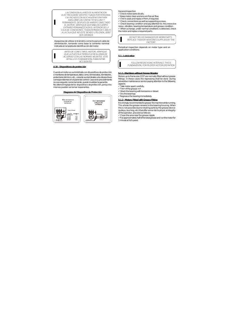
7/17/2019 R05323-P-001A-X009-0042.pdf
http://slidepdf.com/reader/full/r05323-p-001a-x009-0042pdf 204/463
General Inspectionü Check motor periodically.ü Keep motor clean and ensure free air flow.ü Check seals and replace them, if required.ü Check connections as well as supporting screws.ü Check bearing condition and pay attention to: Any excessivenoise, vibration, bearing temperature and grease condition.ü When a change, under normal conditions is detected, checkthe motor and replace required parts.
DO NOT REUSE DAMAGED OR WORN PARTS.REPLACE THEM BY NEW ONES SUPPLIED BY THE
FACTORY
Periodical inspection depends on motor type and onapplication conditions.
5.1 – Lubrication
I
FOLLOW REGREASING INTERVALS. THIS IS FUNDAMENTAL FOR PROPER MOTOR OPERATION I
5.1.1 - Machines without Grease NipplesMotors up to frame size 215T are normally fitted without greasefittings. In these cases the regreasing shall be done duringpreventive maintenance service paying attention to the followingaspects:ü Take motor apart carefully.ü Take all the grease out.ü Wash the bearing with kerosene or diesel.ü Dry the bearingsü Regrease the bearing immediately.
5.1.2 - Motors Fitted with Grease Fitting
It is strongly recommended to grease the machine while running. This allows the grease renewal in the bearing housing. Whenthis is not possible due to rotating parts by the grease device
(pulleys, bushing, etc) that offer some risk to physical integrityof the operator, proceed as follows:ü Clean the area near the grease nipple.ü Put approximately half of the total grease and run the motor for1 minute at full speed.
LA CONEXION A LA RED DE ALIMENTACION ELECTRICA DEBE SER EFECTUADA POR PERSONAL
CALIFICADO CON MUCHA ATENCION PARAASEGURAR UN CONTACTO SEGURO Y
PERMANENTE. DESPUES DE HABER CONECTADO EL MOTOR , VERIFIQUE QUE NINGUN CUERPO EXTRAÑO PERMANEZCA EN EL INTERIOR DE LA
CAJA DE CONEXIONES. TODA ENTRADA DE CABLES A LA CAJA QUE NO ESTE SIENDO UTILIZADA, DEBE
SER CERRADA
ANTES DE CONECTAR EL MOTOR, VERIFIQUE QUE LA PUESTA A TIERRA FUE REALIZADA DE ACUERDO CON LAS NORMAS VIGENTES. ESTE
DETALLE ES FUNDAMENTAL PARA EVITAR ACCIDENTES
Asegúrese de utilizar el diámetro correcto para el cable dealimentación, tomando como base la corriente nominalindicada en la tarjeta de identificación del motor.
I
I
4.10 – Dispositivos de protección
Cuando el motor es suministrado con dispositivos de proteccióno monitoreo de temperatura, tales como, termostatos, termistores,protectores térmicos, etc., conecte sus terminales a los dispositivoscorrespondientes en el panel de control. Caso este procedimientono sea seguido correctamente, puede invalidar la garantía.No altere el reglaje de los dispositivos de protección, porque losmismos pueden se tornar inoperantes.
Diagrama del Dispositivo de Protección
L3L2L1
3x
P1 P2
3x
L1 L3L2
DISPOSITIVODEPROTECCIÓN
CABLESDE
LOSTERMISTORES
P1 P2

7/17/2019 R05323-P-001A-X009-0042.pdf
http://slidepdf.com/reader/full/r05323-p-001a-x009-0042pdf 205/463
Then turn off the motor and pump in the rest of the grease.ü The injection of all the grease with the motor in standstill canmake the grease penetrate into the motor, through the bearinghousing inner seal.Inspections intervals depend on motor type and on applicationconditions.
USE ONLY MANUAL GREASE GUN FOR LUBRICATION I
R E C OMME NDE D
R E L UB R I C A T
I ON
I NT E R V A L S
–P OL Y R E X E M GR
E A S E (
M OB I L )
La tensión y forma de conexión están indicadas en la tarjeta deidentificación del motor.La variación aceptable de tensión es de ±10%,La variación aceptable en la frecuencia es de +3 y –5% y la variacióntotal aceptable de la tensión y frecuencia es de ±10%.Nota: Para rango de tensión nominal (Línea Tru Metric), la variaciónaceptable es ± 5% de acuerdo con la IEC60034-1.
4.9 - Sistema de arranque
Es preferible que el motor arranque en forma directa. En el casode que esto no sea posible, utilizar métodos de arranquealternativos que sean compatibles con la carga y tensión del motor.
Cuando aplicar el sistema de arranque con tensión reducida,acuerde que el par de arranque también reducirá.
ü Los motores 3 cables tensión única y 9 cables doble tensiónpueden ser arrancados como sigue: - Arranque directo a plena tensión- Arranque con auto transformador- Arrancador Suave (Soft-Starter)- Arranque con Convertidor de frecuencia – bajo verificación yanálisis de aplicación.
- Arranque Serie-Paralelo (solamente para 9 cables)
ü Los motores 6 cables tensión única y doble y 12 cables dobletensión pueden ser conectados como sigue:- Arranque directo a plena tensión- Arranque estrella-triangulo- Arranque con auto transformador- Arrancador Suave (Soft-Starter)- Arranque con Convertidor de frecuencia – bajo verificación yanálisis de aplicación.- Arranque Serie- Paralelo (solamente para 12 cables)
El sentido de giro es el horario, mirando el motor desde el extremodel eje y conectando las fases en la secuencia L1, L2 y L3. Estasecuencia y la alimentación deben ser positivas.
Para cambiar el sentido de giro, invertir dos de los cables dealimentación.Nota: Para motores con conexión monofásica, favor verificar latarjeta de identificación del motor.
7/17/2019 R05323-P-001A-X009-0042.pdf
http://slidepdf.com/reader/full/r05323-p-001a-x009-0042pdf 206/463
Note: The table above is specifically intended for relubrification withMOBIL Polyrex EM grease and bearing absolute operatingtemperature of:ü 70ºC (158ºF) for 254/6T to 324/6T frame size motorsü 85ºC (185ºF) for 364/5T to 586/7T frame size motorsFor every 15ºC (59ºF) above these limits, relubrification intervalsmust be reduced by half. Shielded bearing (ZZ) are lubricatedfor bearing life as long are they operate under conditions andtemperature of 70ºC (158ºF).ü Relubrication periods given above are for those cases
applying MOBIL Polyrex® EM grease.ü When motors are used on the vertical position, theirrelubrication interval is reduced by half if compared to horizontalposition motors.ü On applications with high or low temperatures, speed variationetc., the type of grease and relubrication intervals is given on anadditional nameplate attached to the motor.
WE RECOMMENDED TO USE BALLBEARINGS FOR MOTORS DIRECTLY
COUPLED TO THE LOAD I
WARNING:
EXCESS OF GREASE CAN CAUSE BEARING OVERHEATING RESULTING IN COMPLETE DAMAGE.
I5.1.3 - Compatibility of MOBIL Polirex EM grease with othertypes of grease
Containing polyurea thickener and mineral oil, the MOBIL PolyrexEM grease is compatible with other types of grease that contain:
ü Lithium base or complex of lithium or polyurea and highlyrefined mineral oil.ü Inhibitor additive against corrosion, rust and anti-oxidantadditive.
Note:ü Although MOBIL Polyrex EM is compatible with the types of grease given above, we do not recommend mixing it with anyother types of grease.ü If you intend to use a type of grease different than those
requieren rodamientos especiales, bien como alineación axialy radial de los ejes.
ATENCION: UNA EXCESIVA TENSIÓN EN LAS CORREAS
DAÑARÁ LOS RODAM IENTOS Y HASTA PUEDE PROVOCAR LA RUPTURA DEL EJE.
Los acoplamientos utilizados deben soportar vibraciones
radiales y axiales durante la operación. Deben ser tomadoscuidados especiales para evitar que no sean excedidas lascargas permitidas y limites de velocidad de catálogo.
4.8 – Conexión eléctrica
Se debe asegurar que el motor sea conectado correctamenteen la red de transmisión.
Los diámetros de los cables y los dispositivos de proteccióndeben ser diseñados de acuerdo con la corriente nominaldel motor.
Los cap acitores d e los mo tores mo nofásicos pueden retene r energía eléct ric a, mismo c on el motor parado. no tocar los c apacitores y los terminales del mo tor sin verificar qu e no exista
tensión en los mismos.
Con e l mo tor parado , pued e existir energía eléct rica en el interio r de la c aja d e conexiones, para las resistencias de
calentamiento o inclusive para el bobinado.
TODA CONEXION EFECTUADA DE FORMAINCORRECTA PUEDE QUEMAR EL MOTORI
~
PELIGRO
~
PELIGRO

7/17/2019 R05323-P-001A-X009-0042.pdf
http://slidepdf.com/reader/full/r05323-p-001a-x009-0042pdf 207/463
recommended above, first contact WEG.
BEFORE USING STANDARD MOTORS IN SPECIFIC AREAS OR ON SPECIAL APPLIC ATIONS, FIRST
CONTACT THE GREASE MANUFACTURER OR WEG I
5.2 - Assembly and Disassembly
Disassembly and assembly must be done by qualified personnelusing only suitable tools and appropriate methods.
The bearing extractor grips must be applied over the side faceof the inner ring to be disassembled or over an adjacent part.
It is essential to assemble bearings under clean conditions toensure good operation and to avoid damages. New bearingsshall only be taken out from their packages when assemblingthem.
Before installing a new bearing it is required to check the shaftfitting for any sharp edge or strike signals.
For bearing assembly warm their inner parts with suitableequipment – inductive process – or use suitable tools.
6. SPARE PARTS
When ordering spare parts, please specify the full type designationand product code as stated on the motor nameplate. Please alsoinform the motor serial number stated on the nameplate.
7 - VARIABLE FREQUENCY DRIVE MOTORS
7.1 - Standard Motors Line
Motors with voltages up to 575V do not require filters if followthe criteria bellow:
La alineación axial (dimensión “E”) entre mitad de acoplamientosdeben ser ejecutados de acuerdo con las especificaciones delfabricante.
Bajo consulta, WEG puede ofrecer su personal entrenado ytambién equipamiento láser para hacer la alineación/nivelacióndel motor y de la máquina accionada.
La expansión de los componentes puede cambiar las condicionesde alineación/nivelación durante el desempeño.
4.7 – Acoplamientos
Cuando se utilice un acoplamiento por medio de correas ypoleas, se debe seguir las informaciones abajo:
- Remover el dispositivo de bloqueo del eje (caso existir) antesde instalar el motor.- Las correas deben ser estiradas apenas lo suficiente comopara evitar deslizamiento en el funcionamiento, de acuerdo conlas recomendaciones del fabricante de las correas.- Para facilitar la instalación de la polea en el eje, se recomiendacalentar la polea hasta 176°F (80°C) y montar aún caliente,utilizando herramientas apropiadas.- Para evitar daños en los rodamientos y punta del eje, elmontaje y desmontaje de las poleas debe s er hecho conherramientas apropiadas.- Mientras el montaje y desmontaje de una polea, nunca hagapresión o golpes en los rodamientos.- Siempre utilice acoplamientos flexibles, acoplamientos rígidos
Fig. 4.6.3 – Lectu ra Axial y Radial comb inado

7/17/2019 R05323-P-001A-X009-0042.pdf
http://slidepdf.com/reader/full/r05323-p-001a-x009-0042pdf 208/463
N o t e :
1 ) M o t o r s w i t h n a m e p l a t e s h
o w i n g v o l t a g e 3 8 0 - 4
1 5 V / 6 6 0 - 6
9 0 V - 5 0 H z a n d 4 4 0 - 4
8 0 V -
6 0 H z , a n d f e d b y V F D o n v o l t a g e 6 6 0 - 6
9 0 V -
5 0 H z o r 4 8 0 V -
6 0 H z
r e q u i r e f i l t e r s .
2 ) M o t o r s i n f r a m e s i z e s 5 0 4
/ 5 T a n d 5 8 6 / 7 T * w h e n u d e d w i t h V F D
’ s , r e q u i r e i n s u l a t e d
b e a r i n g s .
* O t h e r f r a m e s i z e s , u n d e r r e
q u e s t .
IF SUCH RECOMMENDATIONS AND CRITERIAARE NOT FOLLOWED ACCORDINGLY, MOTOR
WARRANTY WILL BE VOID I
Montaje correcto del acoplamiento:Especialmente en los casos donde se utiliza acoplamiento directo,el eje debe ser alineado axialmente y radialmente con el eje de lamáquina accionada.Una alineación incorrecta puede dañar el rodamiento, vibracionesy hasta provocar ruptura del eje.Una alineación correcta puede ser asegurada con el uso decalibradores, de acuerdo con las figuras 4.6.1, 4.6.2 y 4.6.3.Considerando un giro completo del eje, la desalineación no debeexceder 0.05mm.
Fig. 4.6.1 – Lect ura Axial (en paralelo)
Fig. 4.6.2 – Lect ura radial (c onc entricidad)
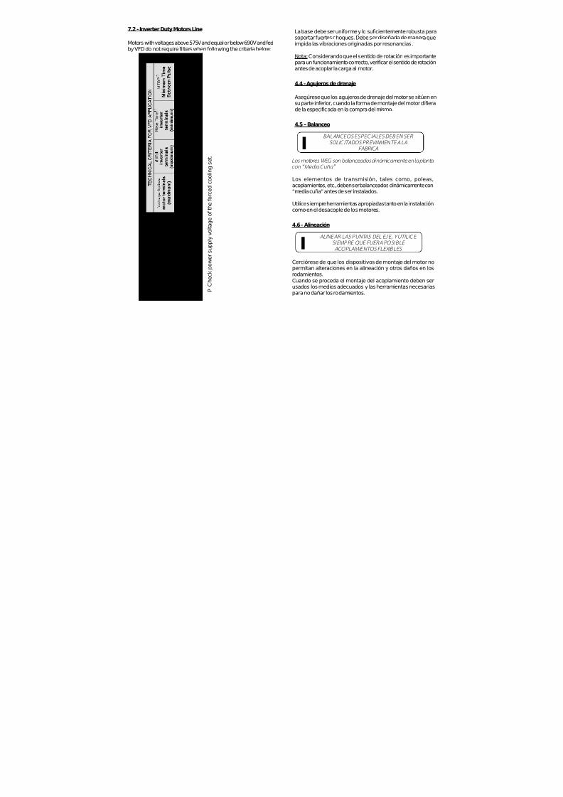
7/17/2019 R05323-P-001A-X009-0042.pdf
http://slidepdf.com/reader/full/r05323-p-001a-x009-0042pdf 209/463
7.2 - Inverter Duty Motors Line
Motors with voltages above 575V and equal or below 690V and fedby VFD do not require filters when following the criteria below:
P
C h e c k p o w e r s u p p l y v o l t a g e o f t h e f o r c e d c o
o l i n g s e t .
La base debe ser uniforme y lo suficientemente robusta parasoportar fuertes choques. Debe ser diseñada de manera queimpida las vibraciones originadas por resonancias.
Nota: Considerando que el sentido de rotación es importantepara un funcionamiento correcto, verificar el sentido de rotaciónantes de acoplar la carga al motor.
4.4 - Agujeros de drenaje
Asegúrese que los agujeros de drenaje del motor se sitúen ensu parte inferior, cuando la forma de montaje del motor difierade la especificada en la compra del mismo.
4.5 – Balanceo
BALANCEOS ESPECIALES DEBEN SER SOLICITADOS PREVIAMENTE A LA
FABRICA
Los mo tores WEG son balanceados dinámicamente en la planta con “Media Cuña”
Los elementos de transmisión, tales como, poleas,acoplamientos, etc., deben ser balanceados dinámicamente con“media cuña” antes de ser instalados.
Utilice siempre herramientas apropiadas tanto en la instalacióncomo en el desacople de los motores.
4.6 – Alineación
ALINEAR LAS PUNTAS DEL EJE, Y UTILICE SIEMPRE QUE FUERA POSIBLE ACOPLAM IENTOS FLEXIBLES
I
ICerciórese de que los dispositivos de montaje del motor no
permitan alteraciones en la alineación y otros daños en losrodamientos.Cuando se proceda el montaje del acoplamiento deben serusados los medios adecuados y las herramientas necesariaspara no dañar los rodamientos.

7/17/2019 R05323-P-001A-X009-0042.pdf
http://slidepdf.com/reader/full/r05323-p-001a-x009-0042pdf 210/463
IF SUCH RECOMMENDATIONS AND CRITERIAARE NOT FOLLOWED ACCORDINGLY, MOTOR
WARRANTY WILL BE VOID I7.3– Bearing insulation
Inverter Duty Motors line in frame sizes 504/5T and 586/7T* aresupplied with ground system between the shaft and frame onDrive Endshield. Also, on request can be supplied with insulated
bearings.
For other lines, in frame sizes 504/5T and 586/7T* when usedwith VFD’s it is required ground system between the shaft andframe or insulated bearings.
(*) Other frame sizes, under request.
8 - ADDITIONAL INSTRUCTIONS
8.1 - Hazardous Area Motors
8.1.1 General
Besides the recommendations given above, theserecommendations must be also followed.Motors for hazardous area are manufactured according tospecific Standards for such environments.Motors supplied for hazardous area (classified areas) must beinstalled in areas that comply with those specified on the motornameplate.
Notes:- Motors of Division I are also suitable for Division II.- Motors of a given class of temperature are suitable also forcombustible environments of a greater class of temperature(example, T4 motors are suitable for environments of class T3,
T2, T1).
8.1.2 Installation
A complete installation must follow procedures given by locallegislation in effect.
la entrada de aire. Una persona debe tener espacio suficientepara mantener servicios de limpieza.Máquinas que son enfriadas a través del aire ambiente, debenlimpiar las entradas de aire en intervalos regulares para asegurarla libre circulación de aire.Aire caliente no puede retornar al motor.Para motores montados en la vertical con las entradas de aireal topo, las entradas de aire deben ser protegidas consombrerete para evitar la caída de cuerpos extraños en el motor.- Considerando que el calor directo del sol causa aumentode temperatura, los motores instalados externamente debensiempre ser protegidos contra la intemperie.
COMPARE LOS VALORES DE CORRIENTE,TENSION, FRECUENCIA, VELOCIDAD, POTENCIA
Y OTROS VALORES EXIGIDOS POR LAAPLICACION, CON LOS DATOS CONTENIDOS EN
LA TARJETA DE IDENTIFICACION
Motores ODP – Motores abiertos (IP21, IP23, etc.):Son motores para uso en locales limpios, secos, concirculación de aire suficiente para su refrigeración. Este tipode motor no debe ser utilizado en la presencia de materialesinflamables o combustibles. Motores abiertos pueden emitirllama/chispa o metal fundido en una eventual falla delaislamiento (cortocircuito).
Motores TCVE – (Totalmente Cerrado VentilaciónExterna): Son motores aptos a trabajar en áreas conhumedad polvo y materiales corrosivos, en ambientes cerradosy también abiertos.
4.3 - Cimentación del motor
Los motores con pies (patas) deberán ser instalados sobreapoyos rígidos para evitar excesivas vibraciones.
Todos los motores deben ser apropiadamente fijados yalineados.El cliente es totalmente responsable de estos apoyos.Las partes metálicas deberán estar pintadas para evitar lacorrosión.
I

7/17/2019 R05323-P-001A-X009-0042.pdf
http://slidepdf.com/reader/full/r05323-p-001a-x009-0042pdf 211/463
When cable entrance is made by a cable gland, this must besuitable to the unit and to the type of cable; the cable gland hasto be assembled, completely screwed in order to get the necessarypressure on the sealing rings, so as to:- Avoid transmission of mechanical vibrations to the motorterminals.- Guarantee mechanical protection “IP” to the terminal box.
8.1.3 Checking and Maintenance
Maintenance must be carried out by repair shops authorizedand accredited by WEG.
Repair shops and people without WEG’s authorization who will
perform any service on hazardous area motors will be fullyresponsible for such service as well as for any consequentialdamage.
When performing maintenance, installation or relubrication,follow these instructions:
ü Electric connections must be correctly locked to avoidresistance-increases, with consequent contact overheating.ü Insulation air-distance and surface-distance betweenconductors, required by the Standards, must be respected.ü All screws, used to assemble parts motor and terminal box,must be completely screwed.ü Seals and components replacement for cable entrance wouldbe made using spare parts, supplied from the manufacturer, in
order to guarantee the original type of protection.ü Explosion Proof motors joint surfaces have not to be machinedand it is not allowed to insert, between them, any kind of seals,not foreseen or suppli ed by the manufacturer. J oint surfaceshave just to be cleaned and, in order to avoid corrosion or water
Utilice siempre herramientas apropiadas para la instalación ydesmontaje.
VERIFIQUE QUE LOS MOTORES ELECTRICOS ESTEN DESCONECTADOS ANTES DE INICIAR CUALQUIER TRABAJO DE MANTENIMIENTO
Todas las partes girantes, tales como poleas, acoplamientos,ventiladores externos, eje, etc., deben estar protegidos contra
toques accidentales.
Los motores deben estar protegidos contra arranquesaccidentales.Al realizar servicios de mantenimiento en el motor, desconectela red de alimentación. Verifique si todos los accesorios fuerondesconectados de la red de alimentación y desligados.
Para impedir la penetración de polvo o agua en el interior dela caja de conexión, es necesario instalar prensa cables oelectroductores roscados en las salidas de los cables. Losmismos deben tener grado IP igual o mayor que el motor.
I
EL AISLAMIENTO DE LOS CABLES, ADENTRO DE
LA CAJA DE CONEXIONES DEL MOTOR, DEBEN SER HECHOS CON MATERIALES COMPATIBLES CON LA CLASE TERMICA DEL MOTOR QUE ESTAMOSTRADA EN LA TARJETA DE IDENTIFICACION
Se las instrucciones de instalación y seguridad no son seguidascorrectamente, se puede perder la garantía.
4.2 - Condiciones de Operación
Los motores eléctricos, en general, son diseñados parainstalación y operación a una altitud hasta 1000m sobre el niveldel mar con temperaturas ambientes de -20ºC (-4ºF) a 40ºC(104ºF).
Variaciones respecto a los valores mencionados deben estarindicadas en la tarjeta de identificación.
La distancia de instalación recomendada entre las entradas deaire del motor y la pared no debe ser inferior ¼ del diámetro de
I
THE SPECIFICATION OF THE MOTOR INSTALLATION SITE IS FOR CUSTOMER’S
RESPONSIBILITY, WHO WILL ALSO DETERMINE THE ENVIRONMENT CHARACTERISTICS
I
THE INSTALLATION OF HAZARDOUS AREAMOTORS MUST BE CARRIED OUT BY SKILLED
PEOPLE I

7/17/2019 R05323-P-001A-X009-0042.pdf
http://slidepdf.com/reader/full/r05323-p-001a-x009-0042pdf 212/463
penetration; they can be oiled by means of a thin coat of silicongrease.ü Check if all components are free of edges, knocks or dirt.ü Make sure all parts are in perfect conditions.ü Lubricate the surfaces of the endshield fittings with protectiveoil to make the assembly easier.ü Use only rubber hammer to fit the parts.ü Check the correct bolts fastening.ü Use clearance calibrator for correct connection terminal boxfitting (less than 0.05mm).
8.1.4 Explosion Proof Motor Repairs
Repair of parts, directly involved in the protection against risk of an explosion, must be done without any modification to theoriginal motor design.
After the repair, these parts must be submitted to a check andwhen concluded, the repair shop must issue a statement, aboutall operations performed on a specific motor.
del estator bobinado. Caso necesario, cambiar los rodamientosy retenedores.
Nota:
1) Los agujeros de drenaje (cuando existan) deben ser retiradosdurante el secado.2) La resistencia de aislamiento debe ser medida en temperaturaambiente. Caso sea diferente de 25°C debe ser corregida utilizandola siguiente formula:
R(25°C)
= [( K+25 ) / ( K + Ta )] . R
(Ta)
Donde:R
(25°C)resistencia del aislamiento relativa a 25°C temperaturaambiente
K valor constante 234.5 para el cobre T
atemperatura ambiente donde la resistencia fue medida
R(Ta)
valor de la resistencia medida en temperatura ambiente Ta
4. INSTALACION
4.1 - Seguridad
Los profesionales que trabajan en instalaciones eléctricas, sea
en el manejo, montaje, operación, puesta en marcha o en elmantenimiento, deberán estar permanentemente informados yactualizados sobre las normas y requisitos vigentes en materiade seguridad y cuidadosamente ponerlas en práctica.
Por motivos prácticos, no es posible incluir en este Manualinformación detallada de todas las variables constructivas,tampoco todas las posibilidades de montaje, operación oalternativas de mantenimiento.Debido a esto, este Manual solamente incluye la informaciónrequerida que recomienda que estos servicios sean efectuadossolamente por personal calificado y entrenado.
Caso Ud. aun tenga alguna duda a este respecto, especialmenterespecto a información especifica del producto, WEG
suministrará esta información a través de su red de servicioautorizado y/o distribuidores.Para permitir que WEG tenga un pronto servicio, dentro de lasnormas técnicas, el número de serie del motor que se encuentraen la tarjeta de identificación debe ser informado.

7/17/2019 R05323-P-001A-X009-0042.pdf
http://slidepdf.com/reader/full/r05323-p-001a-x009-0042pdf 213/463
9. WARRANTY TERMS
WEG warran ts i ts produc ts aga ins t defec t s in workmansh ip and materials for eighteen (18) months from the invoice date issued by the factory, authorized d istributor or agent limited to twenty four (24) months from manufacturing date independ ent of installation date as long as the following items are fulfi l led a c co r d i n g l y :
- Proper transportat ion, handl ing and storage; - Co r r e c t in s t a l l at i o n ba sed on t h e spe c i f i e d am b i e n t env ironmen ta l cond i t i ons ; - Operat ion under motor c apacity l imits; - Observat ion of the periodic al maintenanc e services; - Repair and/or replacement effected only by p ersonnel duly author ized in wri t ing b y WEG; - The failed product b e available t o the supplier and/or repair shop for a required period to detect the c ause of the fai lure and c o r respond ing repa i r ; - Imm ediate not ice by the purchaser about fai lures occurred and that these are acce pted by WEG as manufacturing defects.This warranty does not include d isassembly services at the purch aser facil it ies, transportation co sts with product, tickets,acco mmo da t i on and mea ls fo r techn i ca l pe rsonne l when requested by t he cus tomer .
The warranty service will be on ly carried out at WEG Authorized Repair Shops or at WEG’s facil it ies.Com ponents wh ose useful l i fe, under normal use, is shorter than the warranty period are not co vered by these warranty terms.The repair and/or replacemen t of parts or com ponents, when affected b y WEG and/or any WEG Authorized Repair Shop, will not give warranty extension.This const i tutes WEG’s only warranty in connec t ion with this sa le and the com pany wi l l have no ob l i ga t i on o r l i ab i l i t y wha t s oe ver t o peop l e , t h i r d pa r t i e s , o t h e r equ i pmen t o r ins ta l l a t ions , inc lud ing wi thou t l im i t a t i on , any c la ims fo r consequent ial damage s or labor cos ts .
Las resistencias de calentamiento nunca deben ser energizadasmientras el motor este operando.
Figura 1
Medición de la resistencia del aislamiento
Desconectar el motor de la red de energía antes de hacercualquier medición de la resistencia del aislamiento.Para evitar riesgo de descarga eléctrica, descargue los
terminales después de la medición.
Mida la resistencia del aislamiento antes de poner el motor enservicio y/o cuando haya indicios de humedad en el bobinado.
La resistencia, medida a 25ºC (77ºF), debe ser:
Ri ≥ (20 x U) / (1000 + 2P) [MΩ](Medido con MEGGER a 500 V c.c.);Donde U = tensión (V); P = potencia (kW).
Si la resistencia del aislamiento medida es inferior a 2 MΩ, elbobinado deberá ser secado de acuerdo con lo que sigue:Calentar el estator bobi nado en un horno partiendo de unatemperatura de 80ºC (176ºF) y elevando 5ºC (41ºF) por horahasta llegar a los 105ºC (221ºF); esta última temperatura debepermanecer durante un período mínimo de una hora.Medir se la resistencia del aislamiento del bobinado permanececonstante y con valores dentro de los mínimos recomendados;caso contrario, se deberá proceder a una nueva impregnación
Posición del Dreno
Dreno

7/17/2019 R05323-P-001A-X009-0042.pdf
http://slidepdf.com/reader/full/r05323-p-001a-x009-0042pdf 214/463
MANUAL DE INSTALACION,OPERACION Y
MANTENIMIENTO PARA
MOTORES DE INDUCCIONCarcasas 143/5t hasta 586/7
ü Verifique si ocurrieron daños durante el transporte.ü Verifique los datos de la tarjeta de identificación.üGire el eje con la mano para verificar si está girando libremente.ü Asegurar que el motor no tenga sido expuesto a polvo ohumedad durante el transporte a almacenamiento.
3. ALMACENAMIENTO
Si los motores no fueran inmediatamente instalados, deben ser
almacenados en un local seco, libre de polvo, vibraciones, gasesy vapores corrosivos; dotado de temperatura uniforme,colocándolos en posición normal y sin apoyar sobre ellos otrosobjetos.
La temperatura de almacenaje de los motores debe quedar entre41°F (5°C) y 140°F (60°C), con humedad relativa no excediendoa 50%.
En el caso de motores con más de dos años de almacenaje, sedebe proceder al cambio de rodamientos o a la substitucióntotal de la grasa lubricante después de la limpieza de los mismos.
En los motores monofásicos almacenados durante dos años omás, se debe además cambiar los capacitores (cuando existan).
WEG recomienda girar el eje del motor (manualmente) al menosuna vez al mes y medir la resistencia del aislamiento antes deinstalarlo, en caso de motores almacenados más de 6 meses ocuando están sometidos a ambientes con alta humedad.
Caso el motor dispone de resistencias de calentamiento, estasdeberán ser conectadas durante el periodo de almacenaje casola humedad relativa exceder 50%.
Caso el motor permanecer almacenado por un largo periodosin tener las resistencias de calentamiento conectadas o cuandoestán instaladas pero no en operación, humedad/agua en laparta interna del motor pueden condensar. En estos casos, laagua debe ser drenada removiendo los drenos (tapones)roscados. Después del drenaje hecho, conecte las resistenciasde calentamiento y asegure que el motor este completamenteseco, entonces reinstale los tapones (drenos) para asegurar elgrado de protección correcto. (Vea figura 1).
Transformando Energía en Soluciones
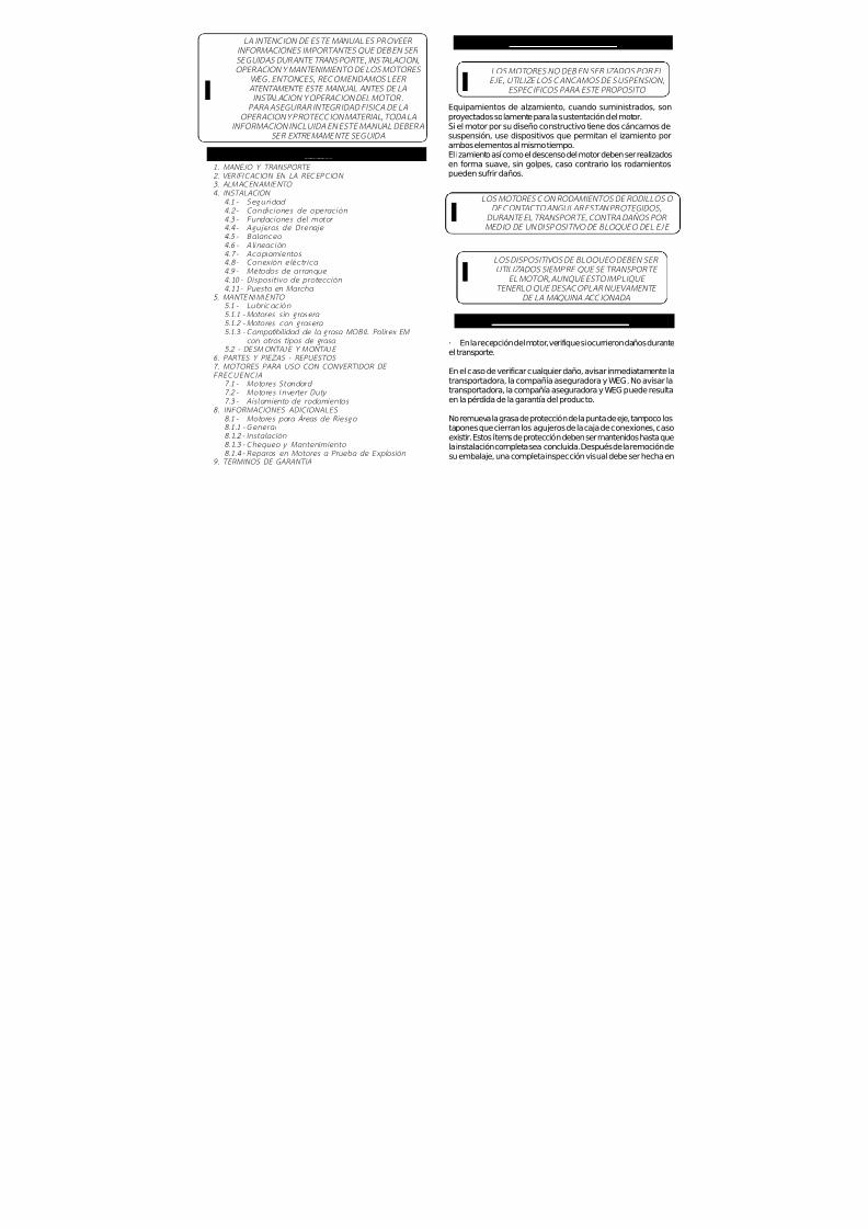
7/17/2019 R05323-P-001A-X009-0042.pdf
http://slidepdf.com/reader/full/r05323-p-001a-x009-0042pdf 215/463
LA INTENCION DE ESTE MANUAL ES PROVEER INFORMACIONES IMPORTANTES QUE DEBEN SER SEGUIDAS DURANTE TRANSPORTE, INSTALACION ,OPERACION Y MANTENIMIENTO DE LOS MOTORES
WEG. ENTONCES, RECOMENDAMOS LEER ATENTAMENTE ESTE MANUAL ANTES DE LAINSTALACION Y OPERACION DEL MOTOR.
PARA ASEGURAR INTEGRIDAD FISICA DE LAOPERACION Y PROTECCION MATERIAL, TODA LA
INFORMACION INCLUIDA EN ESTE MANUAL DEBERA
SER EXTREMAMENTE SEGUIDA
I
INDICE
1. MANEJO Y TRANSPORTE 2. VERIFICACION EN LA RECEPCION 3. ALMACENAMIENTO 4. INSTALACION
4.1 - Se g ur id ad 4.2 - Co n d ic i o n es d e o p e r a c ió n 4.3 - Fu n da c io n es d e l mo t o r 4.4 - A gu je ro s d e D r e na je 4.5 - B ala nc eo 4.6 - Al in ea c ió n 4.7 - Ac o p lam ie nt os 4 .8 - Conex ión e léct r i ca 4 .9 - Métodos de a r ranque 4 .10 - D ispos it i vo de p ro tecc ión 4.11 - Puesta en Marcha
5. MANTENIMIENTO 5.1 - L ub ri ca c ión 5.1.1 - Mo tores sin grasera 5.1 .2 - Motores con grasera 5.1.3 - Compatib i l idad d e la grasa MOBIL Pol i rex EM
con o tros t ipos de grasa 5.2 - DESMONTAJE Y MONTAJE
6. PARTES Y PIEZAS - REPUESTOS 7. MOTORES PARA USO CON CONVERTIDOR DE FRECUENCIA
7.1 - Mo to re s S ta nd a rd 7 .2 - Mo t o re s I nv er te r Du ty 7 .3 - A is lam i en t o de r odam ien to s
8. INFORMACIONES ADICIONALES 8 .1 - Mo to res pa ra Áreas de Riesgo 8.1 .1 - Gen era l 8.1.2 - Instalac ión 8 .1 .3 - Chequeo y Man ten imien to 8.1.4 - Reparos en Moto res a Prueba de Explosión
9. TERMINOS DE GARANTIA
1 – MANEJO Y TRANSPORTE
LOS MOTORES NO DEBEN SER IZADOS POR ELEJE, UTILIZE LOS CANCAMOS DE SUSPENSION,
ESPECIFICOS PARA ESTE PROPOSITO
LOS MOTORES CON RODAMIENTOS DE RODILLOS O DE CONTACTO ANGULAR ESTAN PROTEGIDOS,
DURANTE EL TRANSPORTE, CONTRA DAÑOS POR MEDIO DE UN D ISPOSITIVO DE BLOQUEO DEL EJE
LOS DISPOSITIVOS DE BLOQUEO DEBEN SER UTILIZADOS SIEMPRE QUE SE TRANSPORTE
EL MOTOR, AUNQUE ESTO IMPLIQUE TENERLO QUE DESACOPLAR NUEVAMENTE
DE LA MAQUINA ACCIONADA
Equipamientos de alzamiento, cuando suministrados, sonproyectados solamente para la sustentación del motor.Si el motor por su diseño constructivo tiene dos cáncamos de
suspensión, use dispositivos que permitan el izamiento porambos elementos al mismo tiempo.El izamiento así como el descenso del motor deben ser realizadosen forma suave, sin golpes, caso contrario los rodamientospueden sufrir daños.
I
I
I
2. VERIFICACION EN LA RECEPCION
· En la recepción del motor, verifique si ocurrieron daños duranteel transporte.
En el caso de verificar cualquier daño, avisar inmediatamente latransportadora, la compañía aseguradora y WEG. No avisar latransportadora, la compañía aseguradora y WEG puede resultaen la pérdida de la garantía del producto.
No remueva la grasa de protección de la punta de eje, tampoco lostapones que cierran los agujeros de la caja de conexiones, casoexistir. Estos ítems de protección deben ser mantenidos hasta quela instalación completa sea concluida. Después de la remoción desu embalaje, una completa inspección visual debe ser hecha en

7/17/2019 R05323-P-001A-X009-0042.pdf
http://slidepdf.com/reader/full/r05323-p-001a-x009-0042pdf 216/463
SHIJIAZHUANG KINGDA PUMP INDUSTRY GROUP CO., LTD
TOROMOCHO PROJECT
HARD METAL SLURRY PUMP
LONG-TERM STORAGE INSTRUCTIONS
Hard Metal Slurry Pumps
R05323-P-001A
SHIJIAZHUANG KINGDA PUMP INDUSTRY GROUP Co., Ltd
1st September, 2010

7/17/2019 R05323-P-001A-X009-0042.pdf
http://slidepdf.com/reader/full/r05323-p-001a-x009-0042pdf 217/463
SHIJIAZHUANG KINGDA PUMP INDUSTRY GROUP CO., LTDLONG-TERM STORAGE INSTRUCTIONS
TOROMOCHO PROJECTR05323-P-001A, REV A
1
LONG-TERM STORAGE INSTRUCTIONS
The pumps are shipped fully protected for the commercial shipping and handling that is required for a
given order. Upon receipt, it is necessary that the customer, or an agent of the customer, conduct a
thorough inspection of all pumps and components for completeness of delivery and possible handling
damage. Some small spare parts may be packed separately, if you find damage or loss, please contact
with Kingda and Freight Company immediately.
Al l shortages should be immediately reported to Kingda.
Note: Any components damaged in shipment should be noted and a claim filed by the responsib le
shipping party with the freight company.
Kinda does not warrant any pump or pump components which become damage due to a failure
which adhere to the instructions listed below.
7/17/2019 R05323-P-001A-X009-0042.pdf
http://slidepdf.com/reader/full/r05323-p-001a-x009-0042pdf 218/463
SHIJIAZHUANG KINGDA PUMP INDUSTRY GROUP CO., LTDLONG-TERM STORAGE INSTRUCTIONS
TOROMOCHO PROJECTR05323-P-001A, REV A
2
Outdoor Storage
1. Site selection for outdoor storage of pump and pump components as following:
1.1: Level, well-drained, firm surface, clean, and dry location.
1.2: The environment for pump storage must be dry, dust-free, and well-ventilated. Avoid damage the
bearing because of vibration. The vibration of the storage place is less than 0.2mm/S.
1.3: Isolated or barricaded from possibility of physical damage from transport vehicles, earth working
equipment, and other site erected equipment.
1.4: The inlets and outlets of pumps should be plugged to prevent sundries entering pump cavity.
Accessible for periodic inspection and maintenance.
2. All the pump or pump baseplate should be supported under each corner of its base to allow it to
“breathe”. Supports (steel beams or wood timbers) of significant size and strength should be placed under
each corner. All components shipped in crates and pallets must be located and supported such that air can flow under
and around the shipping container.
3. Upon receipt of the Pump and pump components, an initial inspection must be made to ensure that all
protective coatings and/or devices have not been compromised during shipping and handling.
If discrepancies are found, corrective action must be taken to ensure adequate protection of the
equipment during storage.
Particular attention must be paid to:
(a) All bright steel surfaces, journal and machined; such as shafts, end flanges.
(b) All shaft sleeve and bearing surfaces.
(c) All the roller bearing.
(d) All machined surfaces protected with paint
4. It is recommended that all electric motors be stored indoors. The motors are to be stored and protected
in accordance with the requirements of the motor manufacture. Some motors may have low voltage
internal heaters that are to be energized during storage.
If indoor store is not possible, it is necessary that these pumps and components be covered by a tarp
which is loose enough to let the component breathe. In areas of high relative humidity, it may be
necessary to use a desiccant to keep it free of moisture.
Note: WEG will provide the Motor Storage Instructions on all motors supplied by us.
Some motors may have low voltage internal heaters that are to be energized during storage.

7/17/2019 R05323-P-001A-X009-0042.pdf
http://slidepdf.com/reader/full/r05323-p-001a-x009-0042pdf 219/463
SHIJIAZHUANG KINGDA PUMP INDUSTRY GROUP CO., LTDLONG-TERM STORAGE INSTRUCTIONS
TOROMOCHO PROJECTR05323-P-001A, REV A
3
Covered or Indoor Storage
The pumps should be covered or Indoor Storage. Covered storage will consist of any structure with a roof
to protect pumps and pump components from direct sunshine and rain. Indoor storage will consist of a
closed-in structure that will protect from sun, rain, wind and dust.
It is recommended that all electric drive motors should be stored indoors. The motors are to be stored and
protected in accordance with the requirements of the motor manufacture.
If proper indoor storage is not available, then the sensitive components must be covered with a well
drained and ventilated tarp or tent structure.
Attention during Storage
1. If the storage time is not more than 1 month, It is suggested that the pump should rotate by 1/4 turn
by manual every 1 week.
2. If the storage time is longer than 1 month , it’s recommended that preservative oil is painted on the
inside of the pump. The preservative oil should be replaced every 12 month. (The preservative oil film
must be cleaned before the trial run of the pump).
It is suggested that the pump should rotate by 1/4 turn by manual every 1 week.
For the pumps with packing, if the storage time is too long, replace the old packing.
3. Check all the components every 3 months; if rusted or oxidized, clean the surface and repaint the
preservative oil.
PARTICULAR ATTENTION must be paid to following:
1. Machined surface of rotating parts, as shaft, shaft sleeve, etc.
2. All the roller bearings, adequate lubricating oil should be filled in it to minimize the chance of oxidization
or rust.
3. The temperature of storage environment should not be less than 5 centigrade. It is to prevent the left
water to cracking the water jacket freezingly in the low temperature condition.
4. Measure the insulating resistance of stator with megameter periodically to check if the motor is not
affected with dampness.
5. The end of cable should be packed with adhesive butyl tape to avoid the moisture entering into the
cable.
6. To avoid the quick aging, keep the cable, winding wire and rubber parts away from the direct sunlight,
heat and hot flame.
7. The technical documents should be safely kept from moisture.

7/17/2019 R05323-P-001A-X009-0042.pdf
http://slidepdf.com/reader/full/r05323-p-001a-x009-0042pdf 220/463
SHIJIAZHUANG KINGDA PUMP INDUSTRY GROUP CO., LTDLONG-TERM STORAGE INSTRUCTIONS
TOROMOCHO PROJECTR05323-P-001A, REV A
4
Storage/Maintenance
Period Task Action
Initial receipt of pumps
and pump components
Inventory and
Inspection
Re-establish the integrity of all protective coatings and covering devices. Check
for damage to the surface finish (paint) that may allow rust or corrosion and
repaint as necessary.
-Report any shipping damages to the freight company.
-Report any shortages to Kingda.
After three (3) Months
of StorageInspection
Re-inspect all pump components, making sure no rust or oxidation is starting to
form on machined surfaces. If rust or oxidation is found, the surface(s) must be
cleaned and a protective coating applied.
After six (6) Months ofStorage
Inspection
Re-inspect all pump components, making sure no rust or oxidation is starting to
form on machined surfaces. If rust or oxidation is found, the surface(s) must be
cleaned and a protective coating applied.
The customer shall maintain a Periodic Inspection and Maintenance Log documenting condition and
efforts to maintain the protection of the Pump and components.

7/17/2019 R05323-P-001A-X009-0042.pdf
http://slidepdf.com/reader/full/r05323-p-001a-x009-0042pdf 221/463
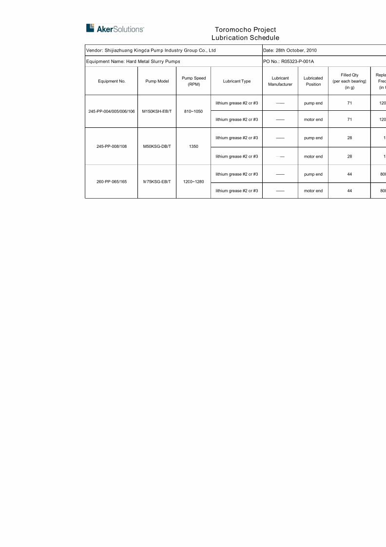
7/17/2019 R05323-P-001A-X009-0042.pdf
http://slidepdf.com/reader/full/r05323-p-001a-x009-0042pdf 222/463
Toromocho Project
Lubrication Schedule
Vendor: Shijiazhuang Kingda Pump Industry Group Co., Ltd Date: 28th October, 2010
Equipment Name: Hard Metal Slurry Pumps PO No.: R05323-P-001A
Equipment No. Pump ModelPump Speed
(RPM)Lubricant Type
Lubricant
Manufacturer
Lubrica
Positio
245-PP-004/005/006/106 M150KSH-EB/T 810~1050
lithium grease #2 or #3 —— pump e
lithium grease #2 or #3 —— motor e
245-PP-008/108 M50KSG-DB/T 1350
lithium grease #2 or #3 —— pump e
lithium grease #2 or #3 —— motor e
260-PP-065/165 M75KSG-EB/T 1200~1280
lithium grease #2 or #3 —— pump e
lithium grease #2 or #3 —— motor e

7/17/2019 R05323-P-001A-X009-0042.pdf
http://slidepdf.com/reader/full/r05323-p-001a-x009-0042pdf 223/463
Tormocho Project
LUBRICATION SCHEDULE
PO Number: R05323-P-001 Equipment: Standard End Suction Pumps
Vendor :SHIJIAZHUANG KINGDA PUMP Vendor contact Name : Wang zhao(Wendy)
page 1 of 1 E-mail :[email protected]
EQUIP NO. DESCRIPTION, WHERE USED LUBRICANT TYPE QUANTITY MANUFACTURERF
R
245-PP-004
245-PP-005
245-PP-006
245-PP-106
Front bearing NU322-C3POLYREX EM
(polyurea grease
60g
MOBIL
Rear bearing 6319-C3 45g
245-PP-008/108Front bearing NU319-C3 POLYREX EM
(polyurea grease
45gMOBIL
Rear bearing 6316-C3 34g
260-PP-065/165Front bearing NU319-C3 POLYREX EM
(polyurea grease
45gMOBIL
Rear bearing 6316-C3 34g
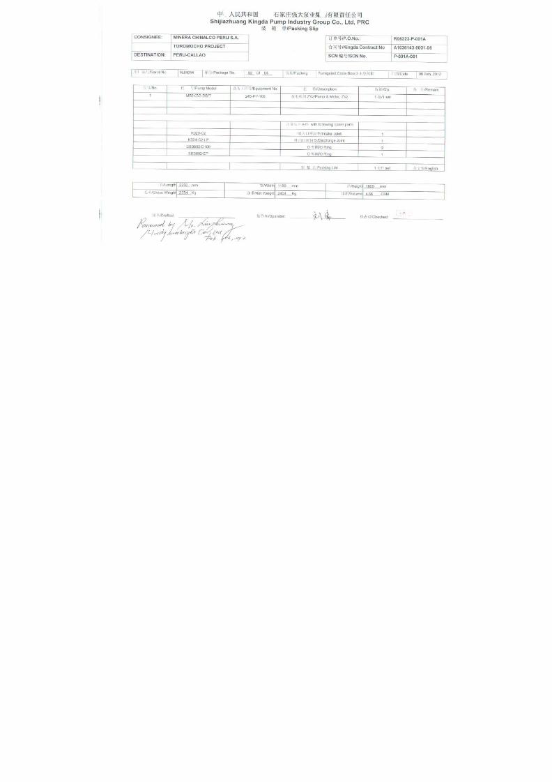
7/17/2019 R05323-P-001A-X009-0042.pdf
http://slidepdf.com/reader/full/r05323-p-001a-x009-0042pdf 224/463
7/17/2019 R05323-P-001A-X009-0042.pdf
http://slidepdf.com/reader/full/r05323-p-001a-x009-0042pdf 225/463

7/17/2019 R05323-P-001A-X009-0042.pdf
http://slidepdf.com/reader/full/r05323-p-001a-x009-0042pdf 226/463
WEG INDÚSTRIAS S/A
ELECTRIC MOTOR WIRING DIAGRAM
• SINGLE SPEED 380V 60HZ MOTOR:

7/17/2019 R05323-P-001A-X009-0042.pdf
http://slidepdf.com/reader/full/r05323-p-001a-x009-0042pdf 227/463
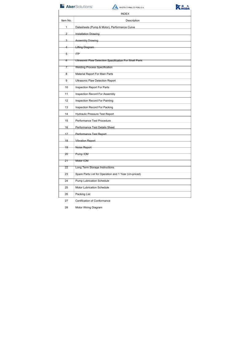
7/17/2019 R05323-P-001A-X009-0042.pdf
http://slidepdf.com/reader/full/r05323-p-001a-x009-0042pdf 228/463
INDEX
Item No. Description
1 Datasheets (Pump & Motor), Performance Curve
2 Installation Drawing
3 Assembly Drawing
4 Lifting Diagram
5 ITP
6 Ultrasonic Flaw Detection Specification For Shaft Parts
7 Welding Process Specification
8 Material Report For Main Parts
9 Ultrasonic Flaw Detection Report
10 Inspection Report For Parts
11 Inspection Record For Assembly
12 Inspection Record For Painting
13 Inspection Record For Packing
14 Hydraulic Pressure Test Report
15 Performance Test Procedure
16 Performance Test Details Sheet
17 Performance Test Report
18 Vibration Report
19 Noise Report
20 Pump IOM
21 Motor IOM
22 Long Term Storage Instructions
23 Spare Parts List for Operation and 1 Year (Un-priced)
24 Pump Lubrication Schedule
25 Motor Lubrication Schedule
26 Packing List
27 Certification of Conformance
28 Motor Wiring Diagram

7/17/2019 R05323-P-001A-X009-0042.pdf
http://slidepdf.com/reader/full/r05323-p-001a-x009-0042pdf 229/463

7/17/2019 R05323-P-001A-X009-0042.pdf
http://slidepdf.com/reader/full/r05323-p-001a-x009-0042pdf 230/463

7/17/2019 R05323-P-001A-X009-0042.pdf
http://slidepdf.com/reader/full/r05323-p-001a-x009-0042pdf 231/463

7/17/2019 R05323-P-001A-X009-0042.pdf
http://slidepdf.com/reader/full/r05323-p-001a-x009-0042pdf 232/463

7/17/2019 R05323-P-001A-X009-0042.pdf
http://slidepdf.com/reader/full/r05323-p-001a-x009-0042pdf 233/463
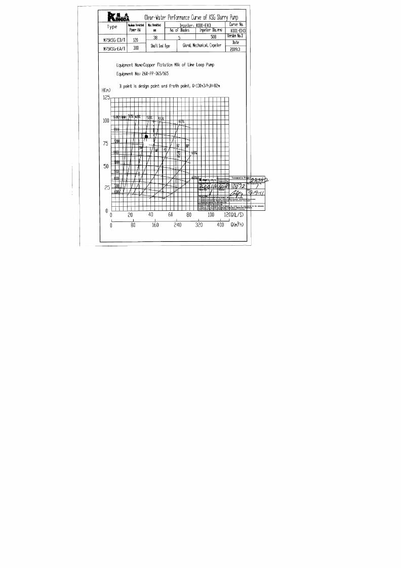
7/17/2019 R05323-P-001A-X009-0042.pdf
http://slidepdf.com/reader/full/r05323-p-001a-x009-0042pdf 234/463

7/17/2019 R05323-P-001A-X009-0042.pdf
http://slidepdf.com/reader/full/r05323-p-001a-x009-0042pdf 235/463
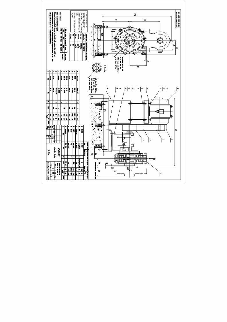
7/17/2019 R05323-P-001A-X009-0042.pdf
http://slidepdf.com/reader/full/r05323-p-001a-x009-0042pdf 236/463
C E RT I F I E DF OR
C ON S T R U C T I ON
B y : W an gZ h a o ( W en d y )
D a t e: 2 5 O c t o b er 2 0 1 0
Mf r :
S HI J I A Z H UA N GK I N GDA
P UMP

7/17/2019 R05323-P-001A-X009-0042.pdf
http://slidepdf.com/reader/full/r05323-p-001a-x009-0042pdf 237/463

7/17/2019 R05323-P-001A-X009-0042.pdf
http://slidepdf.com/reader/full/r05323-p-001a-x009-0042pdf 238/463
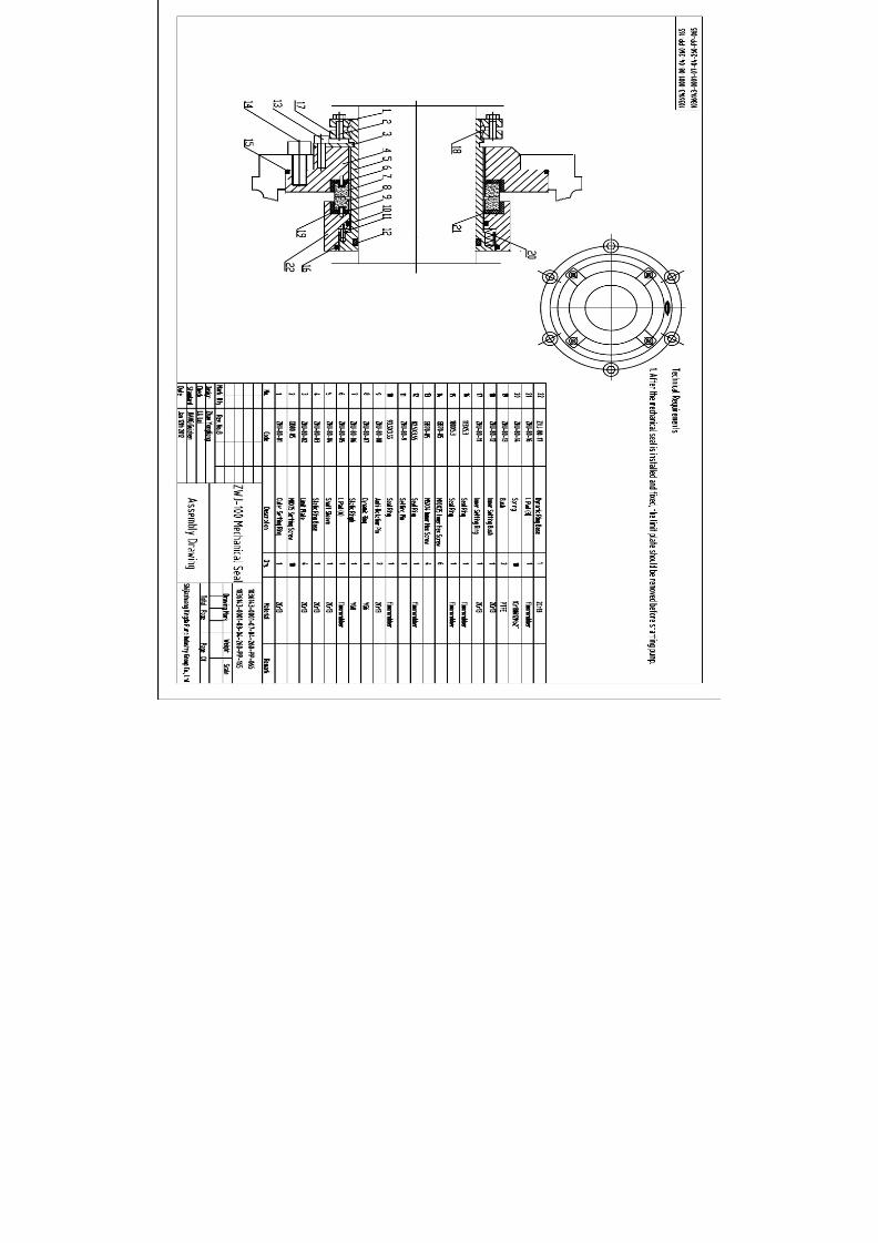
7/17/2019 R05323-P-001A-X009-0042.pdf
http://slidepdf.com/reader/full/r05323-p-001a-x009-0042pdf 239/463

7/17/2019 R05323-P-001A-X009-0042.pdf
http://slidepdf.com/reader/full/r05323-p-001a-x009-0042pdf 240/463

7/17/2019 R05323-P-001A-X009-0042.pdf
http://slidepdf.com/reader/full/r05323-p-001a-x009-0042pdf 241/463

7/17/2019 R05323-P-001A-X009-0042.pdf
http://slidepdf.com/reader/full/r05323-p-001a-x009-0042pdf 242/463
No. 239, Tianshan Street, Shijiazhuang City, Hebei Province, ChinaTel: +86 311 80908109 Fax: +86 311 80908116 Email: [email protected]
Inspection and Test Plan
PO No.: R05323-P-001A, Equipment Name: Hard Metal Slurry Pumps
Item
No.
Inspection &
Test Item
Acc eptance
Criteria
Inspection
Methods
Acceptance
Doc.
Review
Doc.
Executive
Time Ma
1 Acceptance of Contract Documents
1.1 Contract Inspection
Signed Contract and
Requirements
Check the Contract and
Requirements
Requirements
by the Contract
Vendor
Departm
1.2
Dimensional
Drawings
Certified Drawings and
Documents
Drawings and Document
Inspection
Drawings submitted
by Vendor
Vendor
Departm
2 Inspectio n on Raw Materials and Purchased Parts
2.1
Inspection of raw
materials
JB/T8096-1998
GB9439-1998
(ASTM A48-2003)
GB1348-1998
(ASTM A536-2003)
GB2100-2002
(ASTM A743/743a-1993a)
GB/T8263-1999
(ASTM A532M-99)
GB699-1988
(ASTM A36/A36M-2005)
SBB121.1-29-1997
SBB125.1-28-1997
SBB302.1-12-2008
SBB0158-2003
Visual inspection, Chemical test,
Spectrometer, General gauge
Comply with the
Standards
Material Composition
Analysis and Mechanical
Prosperities Report,
Product Compliance
Certificate
After arrival at
Factory
Quality
Dept.
2.2 Bearings
Contract Technical
Requirements
Visual inspection, check Product
Compliance Certificate
Comply with
Contract technical
Product Compliance
After arrival at
Factory
Quality
Manage

7/17/2019 R05323-P-001A-X009-0042.pdf
http://slidepdf.com/reader/full/r05323-p-001a-x009-0042pdf 243/463
No. 239, Tianshan Street, Shijiazhuang City, Hebei Province, ChinaTel: +86 311 80908109 Fax: +86 311 80908116 Email: [email protected]
requirement Dept.
2.3 WEG Motors
Contract Technical
Requirements
Visual inspection, check Product
Compliance Certificate
Comply with
Contract technical
requirement
Product Compliance
After arrival at
Factory
Quality
Manage
Dept.
3 Inspectio n and Test in Pump Product ion Process
3.1
Inspection Before
Casting
SBB139-2001
SBB131-1998
SBB122-2000
Spectrometer
Comply with the
Standards
Material Composition
Analysis and Mechanical
Prosperities Report
Before Pouring
Quality
Manage
Dept.
3.2 Castings
SBB139-2001
SBB122-2000
SBB131-1998
GB1348-1988
(ASTM A536-2003)
Spectrometer,
Carbon-Sulfur Analyzer,
Chemical Test, General Gauge
Comply with the
Standards
Material Composition
Analysis and Mechanical
Prosperities Report
After
heat treatment
Quality
Dept.
3.3 Heat TreatmentSBB131-1998
SBB165-2009
Hardness Tester,
Universal Tester
Comply with the
Standards
Heat Treatment
Report
After
heat treatment
Quality
Manage
Dept.
3.4
Inspection in
Machining Process
SBB2105-87
SBB061-2003
Drawing Requirements
General Tools,
Special Tools
Comply with the
Standards and
Drawing
Requirements
Machining Dimension
Inspection Record
During
Machining
Process
Quality
Manage
Dept.
3.5
Impeller Static
Balancing,
SBB061-2003 Balancing Test Frame
Comply with the
Standard
Impeller Static Blancing
Report
Static Balance
Test
Quality
Manage
Dept.
3.6 Shafft Inspection YB-T036.T-92 Ultrasonic Detection
Comply with the
Standard
Shaft Ultrasonics
Detection Report
Shaft Inspection
Test
Quality
Manage
Dept.
4 Assembl y, Test, Painting and Packing
4.1 Assembly SBB2103-2000 General Gauge
Comply with the
Standards and
Clearance Inspection
Record in Assembly
After Assembly
Quality
Dept.

7/17/2019 R05323-P-001A-X009-0042.pdf
http://slidepdf.com/reader/full/r05323-p-001a-x009-0042pdf 244/463
No. 239, Tianshan Street, Shijiazhuang City, Hebei Province, ChinaTel: +86 311 80908109 Fax: +86 311 80908116 Email: [email protected]
SBB064-2004
Drawing Requirements
Drawing
Requirements
4.2
Hydraulic
Pressure Test
GB/T5656-94,
SBB064-1998,
(HI 1.6-2000/API610)
Visual Inspection,
Pressure gauge
Comply with the
standards
Hydraulic Pressure Test
Report
After Assembly,
Witness Point
Quality
Dept.
4.3
Performance
Noise
Vibration
Contract Technical
Requirements
GB3216-2005
(HI 1.6-2000/
ASME B73.1M/B73.2M)
JB/T8097-1999
GB3214-91,
GB10890,
GB10889
SBB064-2004
Pump Test Station
Comply with the
Standards and
Contract Technical
Requirements
Pump Performance
Running Test Report
After Assembly,
Witness Point
Quality
Dept.
4.4 Painting
Contract Technical
Requirements SBB097-2008
SBB0159-1998
JB/T4297-1992
Visual Inspection,
Coating Thickness Meter
Comply with the
Standards and
Contract Technical
Requirements
Assembly Inspection
Record
After Painting
Quality
Dept.
4.5 Packing
Contract Technical
Requirements
SBB0157-1997
SBB0167-2009
GB/T13384-1992
Visual Inspection
Comply with the
Standards and
Contract Technical
Requirements
Assembly Inspection
Record
After Packing
Quality
Dept.
5 Relese for Shippment
5.1
Release for
shipment
Contract requirements As per Contract Requirements
Release for
shipment from
Owner
Hold Point

7/17/2019 R05323-P-001A-X009-0042.pdf
http://slidepdf.com/reader/full/r05323-p-001a-x009-0042pdf 245/463
ULTRASONIC FLAW DETECTION
SPECIFICATION
FOR
SHAFT PARTS
TOROMOCHO PROJECT
Supplier: SHIJIAZHUANG KINGDA PUMP INDUSTRY GROUP CO., LTD
Reviewed And Approved:
Date: November, 2011

7/17/2019 R05323-P-001A-X009-0042.pdf
http://slidepdf.com/reader/full/r05323-p-001a-x009-0042pdf 246/463
SHIJIAZHUANG KINGDA PUMP INDUSTRY GROUP CO., LTDULTRASONIC FLAW DETECTION SPECIFICATIONDoc No.: WPS-UD-2011, Date: Nov, 2011, Rev 00
NO. 239, TIANSHAN STREET, SHIJIAZHUANG CITY, HEBEI PROVINCE, CHINA
GENERAL TECHNICAL SPECIFICATION
FOR ULTRASONIC FLAW DETECTIOIN FOR SHAFT PARTS
1. General Provision
1.1 Application Scope
This Specification applies for the testing of internal incontinuity of forgings sourced by Kingda by using A
Type Pulse Reflection Ultrasonic Detection method.
This Specification is not applied to work piece of austenite coarse grained.
1.2 Acceptance Standard
GB/T 4162 Forged And Rolled Steel Bars - Method For Ultrasonic Testing
GB/T 7736 Ultrasonic Inspecting Method For Macro-Structure And Imperfection Of Steel
1.3 If special requirements, inspection and acceptance will be carried as per Standards in relative
agreements, drawing and process.
1.4 Requirements for Inspectors
The inspectors should have Ultrasonic Flaw Detection Technology Certification, and the Inspector who will
sign the Report must be qualified for II Grade or Above Certification.
2. Detection Equipment And Instruments
2.1 Ultrasonic Flaw Detector
The ultrasonic flaw detector should be tested for its fuction as per the methods specified in JB/T
10061-1999, and its quota should be meet following:
a). Surplus Sensitivity: N≥36dB
b). Vertical Linearity Tolerance: D≤6%
c). Horizontal Linearity Tolerance: δ≤1%
d). Dynamic Range: ≥30dB.
2.2 Probe
Usually straight beam probe is selected for detection; angle beam probe is selected for assistant detection.
The operation frequency of probe must meet the requirements to penetrate and explore the work piece,
nominal frequency of 2-5MHz is used, and probe crystal diameter or side length is 10-25mm.
2.3 Coupling Medium
Coupling medium whichever can give good coupling effect and is not harmful to body and work piece
should be selected.
The same coupling medium must be used for adjustment, calibration and inspection of equipments.
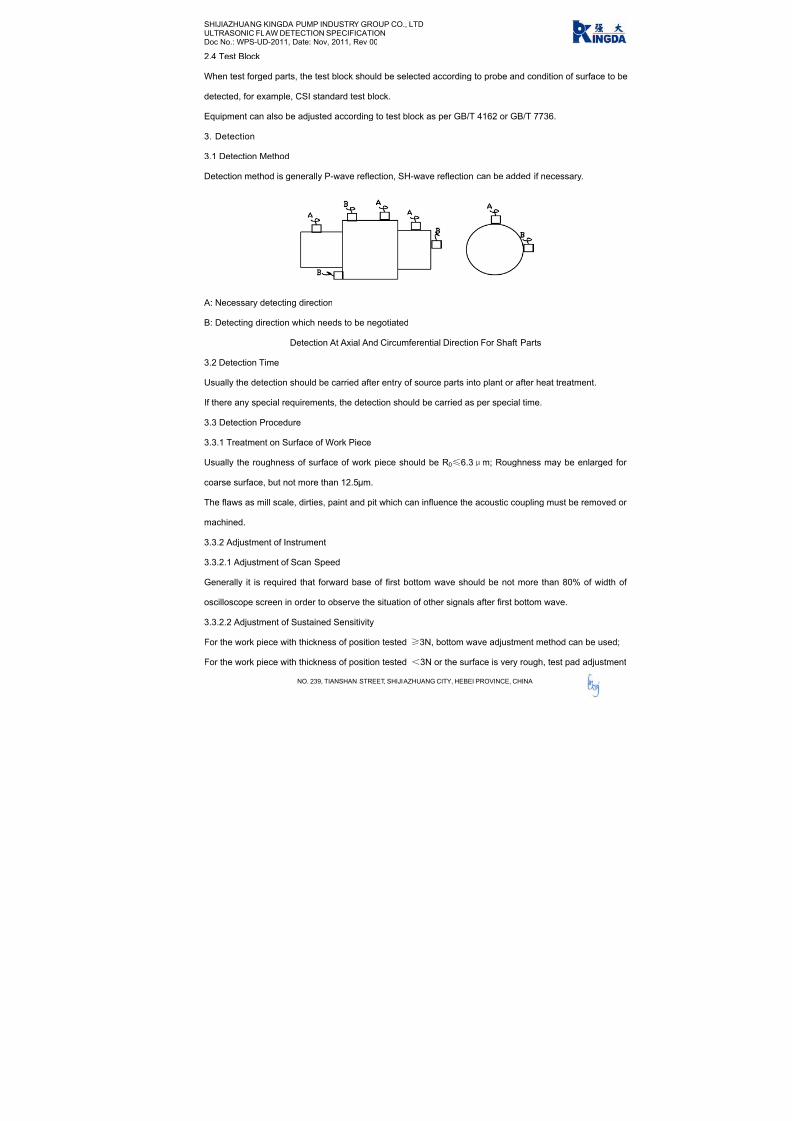
7/17/2019 R05323-P-001A-X009-0042.pdf
http://slidepdf.com/reader/full/r05323-p-001a-x009-0042pdf 247/463
SHIJIAZHUANG KINGDA PUMP INDUSTRY GROUP CO., LTDULTRASONIC FLAW DETECTION SPECIFICATIONDoc No.: WPS-UD-2011, Date: Nov, 2011, Rev 00
NO. 239, TIANSHAN STREET, SHIJIAZHUANG CITY, HEBEI PROVINCE, CHINA
2.4 Test Block
When test forged parts, the test block should be selected according to probe and condition of surface to be
detected, for example, CSI standard test block.
Equipment can also be adjusted according to test block as per GB/T 4162 or GB/T 7736.
3. Detection
3.1 Detection Method
Detection method is generally P-wave reflection, SH-wave reflection can be added if necessary.
A: Necessary detecting direction
B: Detecting direction which needs to be negotiated
Detection At Axial And Circumferential Direction For Shaft Parts
3.2 Detection Time
Usually the detection should be carried after entry of source parts into plant or after heat treatment.
If there any special requirements, the detection should be carried as per special time.
3.3 Detection Procedure
3.3.1 Treatment on Surface of Work Piece
Usually the roughness of surface of work piece should be R0≤6.3μm; Roughness may be enlarged for
coarse surface, but not more than 12.5μm.
The flaws as mill scale, dirties, paint and pit which can influence the acoustic coupling must be removed or
machined.
3.3.2 Adjustment of Instrument
3.3.2.1 Adjustment of Scan Speed
Generally it is required that forward base of first bottom wave should be not more than 80% of width of
oscilloscope screen in order to observe the situation of other signals after first bottom wave.
3.3.2.2 Adjustment of Sustained Sensitivity
For the work piece with thickness of position tested ≥3N, bottom wave adjustment method can be used;
For the work piece with thickness of position tested <3N or the surface is very rough, test pad adjustment

7/17/2019 R05323-P-001A-X009-0042.pdf
http://slidepdf.com/reader/full/r05323-p-001a-x009-0042pdf 248/463
SHIJIAZHUANG KINGDA PUMP INDUSTRY GROUP CO., LTDULTRASONIC FLAW DETECTION SPECIFICATIONDoc No.: WPS-UD-2011, Date: Nov, 2011, Rev 00
NO. 239, TIANSHAN STREET, SHIJIAZHUANG CITY, HEBEI PROVINCE, CHINA
method can be used.
When the surface shape and roughness of test pad is different from the work piece, coupling compensation
and attenuation compensation methods can be used.
3.3.2.3 Adjustment of Scan Sensitivity
6dB should be amplified based on the inspection sensitivity in order to easily find the defects, but estimation
on the defects should be based on the inspection sensitivity level.
3.4 Inspection Frequency
3.4.1 If no special requirement, the sample test should be made as per SBB302.1-2008.
3.4.2 If any special requirements, the test should be made as per requirements.
3.4.3 For the tested work piece, whole detecting should be made.
3.5 Scan Detection
3.5.1 Scan Type
Usually whole scan should be used.
3.5.2 Scan Speed
In order to ensure the defects can be clearly found, the scan speed should not more than 150mm/s.
3.5.3 Scan Distance
It is required that 15% overlapping should be done between two scans.
3.6 Calibration of Instruments
After detection, the instrument should be calibrated for sensitivity; if the sensitivity can not meet the
requirements, calibration should be done.
4. Estimation of Defects
Usually defects will be estimated according to the reflection and bottom reflection results, including defect
position and size, if necessary, the nature of defects can be estimated.
4.1 Estimation of Defect Position
To determine the surface position of defect according to the probe work position;
To determine he depth of defects according to that tested in oscilloscope screen.
4.2 Estimation of Defect Size
4.2.1 For flat defect of small wafer size, equivalent size of defect should be estimated according to the echo
margin shown in oscilloscope screen.
4.2.2 For flat defect of large wafer size, the length and area of defect should be estimated by 6dB or half
wave height method.

7/17/2019 R05323-P-001A-X009-0042.pdf
http://slidepdf.com/reader/full/r05323-p-001a-x009-0042pdf 249/463
SHIJIAZHUANG KINGDA PUMP INDUSTRY GROUP CO., LTDULTRASONIC FLAW DETECTION SPECIFICATIONDoc No.: WPS-UD-2011, Date: Nov, 2011, Rev 00
NO. 239, TIANSHAN STREET, SHIJIAZHUANG CITY, HEBEI PROVINCE, CHINA
4.2.3 For the defect of volume type, circumferential direction detection method can be used.
5. Quality Estimation
Estimation should be made as per GB/T 4162 and GB/T 7736; if any, special requirements can be followed.
After the detection, if disputes, it can be confirmed by low-power etch test.
6. Inspection Record And Report
6.1 Inspection report include: specification, grade, heat number, standard, quality grade and quantity,
issued by who and date, etc.
6.2 Inspection record should include position of defect, size of equivalent, distance and length of defects,
and drop of bottom wave, etc.

7/17/2019 R05323-P-001A-X009-0042.pdf
http://slidepdf.com/reader/full/r05323-p-001a-x009-0042pdf 250/463
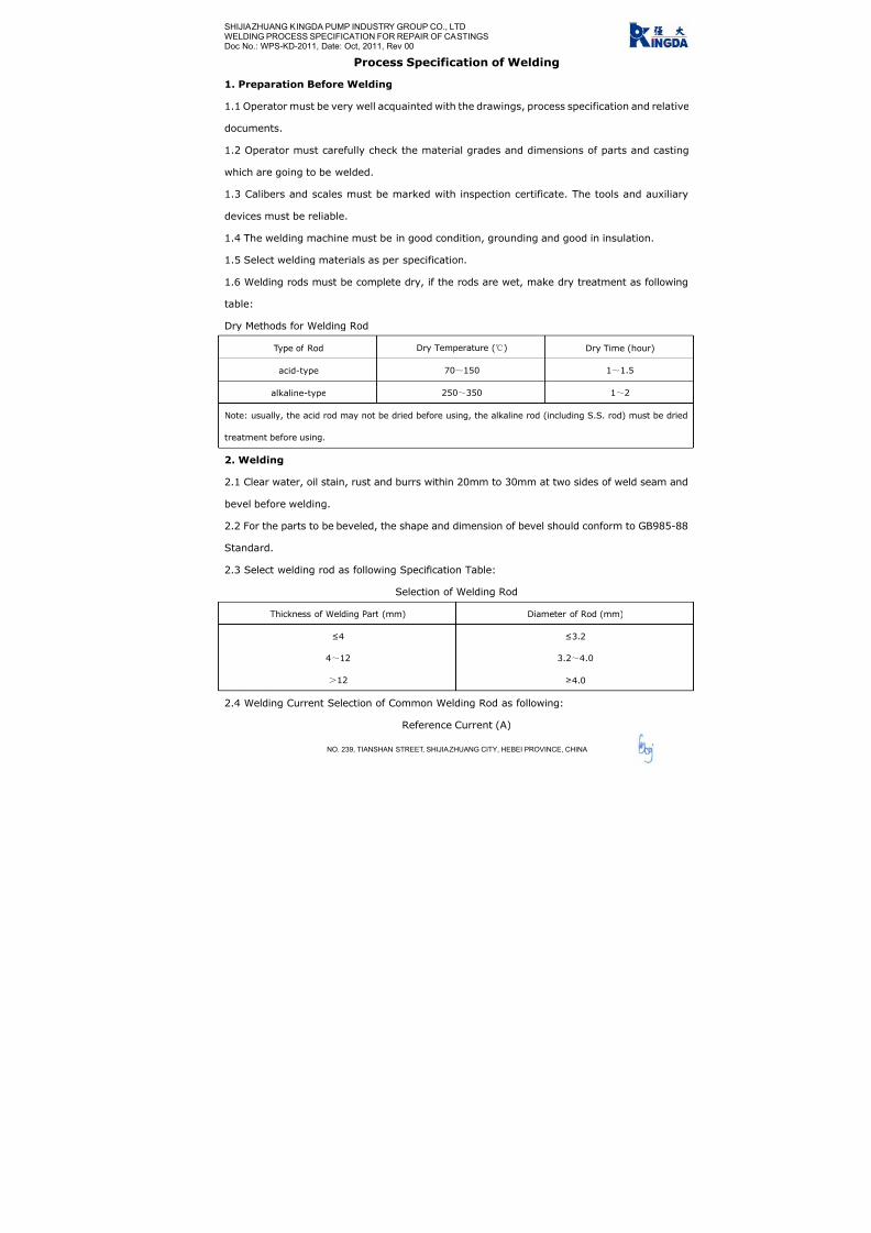
7/17/2019 R05323-P-001A-X009-0042.pdf
http://slidepdf.com/reader/full/r05323-p-001a-x009-0042pdf 251/463
SHIJIAZHUANG KINGDA PUMP INDUSTRY GROUP CO., LTD
WELDING PROCESS SPECIFICATION FOR REPAIR OF CASTINGS
Doc No.: WPS-KD-2011, Date: Oct, 2011, Rev 00
NO. 239, TIANSHAN STREET, SHIJIAZHUANG CITY, HEBEI PROVINCE, CHINA
Process Specification of Welding
1. Preparation Before Welding
1.1 Operator must be very well acquainted with the drawings, process specification and relative
documents.
1.2 Operator must carefully check the material grades and dimensions of parts and casting
which are going to be welded.
1.3 Calibers and scales must be marked with inspection certificate. The tools and auxiliary
devices must be reliable.
1.4 The welding machine must be in good condition, grounding and good in insulation.
1.5 Select welding materials as per specification.
1.6 Welding rods must be complete dry, if the rods are wet, make dry treatment as following
table:
Dry Methods for Welding Rod
Type of Rod Dry Temperature () Dry Time (hour)
acid-type 70~150 1~1.5
alkaline-type 250~350 1~2
Note: usually, the acid rod may not be dried before using, the alkaline rod (including S.S. rod) must be dried
treatment before using.
2. Welding
2.1 Clear water, oil stain, rust and burrs within 20mm to 30mm at two sides of weld seam and
bevel before welding.
2.2 For the parts to be beveled, the shape and dimension of bevel should conform to GB985-88
Standard.
2.3 Select welding rod as following Specification Table:
Selection of Welding Rod
Thickness of Welding Part (mm) Diameter of Rod (mm)
≤4
4~12
>12
≤3.2
3.2~4.0
≥4.0
2.4 Welding Current Selection of Common Welding Rod as following:
Reference Current (A)
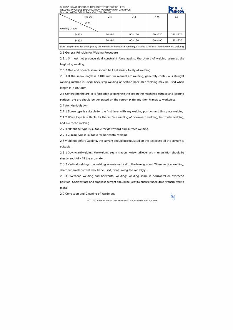
7/17/2019 R05323-P-001A-X009-0042.pdf
http://slidepdf.com/reader/full/r05323-p-001a-x009-0042pdf 252/463
SHIJIAZHUANG KINGDA PUMP INDUSTRY GROUP CO., LTD
WELDING PROCESS SPECIFICATION FOR REPAIR OF CASTINGS
Do .: WPS-KD-2011, Date: Oct, 2011, Rev 00
NO. 239, TIANSHAN STREET, SHIJIAZHUANG CITY, HEBEI PROVINCE, CHINA
c No
Rod Dia.
(mm)
Welding Grade
2.5 3.2 4.0 5.0
E4303 70~90 90~130 160~220 220~270
E4303 70~90 90~130 160~190 180~230
Note: upper limit for thick plate; the current of horizontal welding is about 10% less than downward welding.
2.5 General Principle for Welding Procedure
2.5.1 It must not produce rigid constraint force against the others of welding seam at the
beginning welding.
2.5.2 One end of each seam should be kept shrink freely at welding.
2.5.3 If the seam length is ≤1000mm for manual arc welding, generally continuous straight
welding method is used; back-step welding or section back-step welding may be used when
length is ≥1000mm.
2.6 Generating the arc: it is forbidden to generate the arc on the machined surface and locating
surface; the arc should be generated on the run-on plate and then transit to workpiece.
2.7 Arc Manipulation
2.7.1 Screw type is suitable for the first layer with any welding position and thin plate welding.
2.7.2 Wave type is suitable for the surface welding of downward welding, horizontal welding,
and overhead welding.
2.7.3 “8” shape type is suitable for downward and surface welding.
2.7.4 Zigzag type is suitable for horizontal welding.
2.8 Welding: before welding, the current should be regulated on the test plate till the current is
suitable.
2.8.1 Downward welding: the welding seam is at on horizontal level. arc manipulation should be
steady and fully fill the arc crater.
2.8.2 Vertical welding: the welding seam is vertical to the level ground. When vertical welding,
short arc small current should be used, don’t swing the rod bigly.
2.8.3 Overhead welding and horizontal welding: welding seam is horizontal or overhead
position. Shortest arc and smallest current should be kept to ensure fused drop transmitted to
metal.
2.9 Correction and Cleaning of Weldment

7/17/2019 R05323-P-001A-X009-0042.pdf
http://slidepdf.com/reader/full/r05323-p-001a-x009-0042pdf 253/463
SHIJIAZHUANG KINGDA PUMP INDUSTRY GROUP CO., LTD
WELDING PROCESS SPECIFICATION FOR REPAIR OF CASTINGS
Doc No.: WPS-KD-2011, Date: Oct, 2011, Rev 00
NO. 239, TIANSHAN STREET, SHIJIAZHUANG CITY, HEBEI PROVINCE, CHINA
2.9.1 Make the correction on the deforms produced in welding with flame correction or
mechanical correction.
2.9.2 Clean spatters, slags and flashes after welding.
2.9.3 The key parts and rigid parts should be distressing tempering treatment after welding.
3. Quality Requirements
3.1 Inspect the weldments for surface appearance and quality as per drawing and specification.
3.2 Welding seam should conform to Welding Seam Quality Standard.

7/17/2019 R05323-P-001A-X009-0042.pdf
http://slidepdf.com/reader/full/r05323-p-001a-x009-0042pdf 254/463
SHIJIAZHUANG KINGDA PUMP INDUSTRY GROUP CO., LTD
WELDING PROCESS SPECIFICATION FOR REPAIR OF CASTINGS
Doc No.: WPS-KD-2011, Date: Oct, 2011, Rev 00
NO. 239, TIANSHAN STREET, SHIJIAZHUANG CITY, HEBEI PROVINCE, CHINA
Process Specification for Weld Repair of Iron Casting
1. Permission Condition for Welding Repair
1.1 When the castings need to be welded repair, it must be approved by Quality Management
Department.
1.2 The permissive condition for the casting welded repair should conform to SBB122 <Pump
Casting Technical Conditions>, drawing and requirements in Contract.
2. Selection of Welding Method
Generally arc welding is used for casting weld repair, arc welding is divided into cold welding
and heat welding.
Application Range: Generally, welding repair will be used at non-machined position which has
low requirement for stress or strength or for defects found in and after machining or fine
machining. Because the correction of heat treatment after weld repair can not be used, in the
condition that its function (quality and precision) will not be influenced by the deformation or
stress caused by partial heating, cold arc welding may be used; when the heating material will
easily crack, heat arc welding can be used.
For iron casting, cold arc welding usually is used.
3. Preparation before Welding
3.1 Clean up the impurities at defect of casting with shovel, chisel, grinding wheel or other
methods, make it to be V shape with 60-80° or X bevel to expose the metal, sharp angle must
be rounded. All existing web cracks were arrested by drilling 4-8mm holes at the ends of the
cracks.
3.2 Remove the oil dirty at and around the defects with solution or flame.
3.3 Brush muddy water all around defect to avoid weld drop attach the machined surface.
3.4 Use Z308 pure nickel rod (Ф3.2, Ф4.2), this rod is required to be kept for 1 hour at temperature of
80-120.
3.5 Generally, preheating is not required for cold arc welding; if preheating required, written
approval must be obtained from Quality Department.
4. Welding Repair
4.1 Selection of Rod Diameter and Welding Current
Rod Diameter (mm) Welding Current (A)
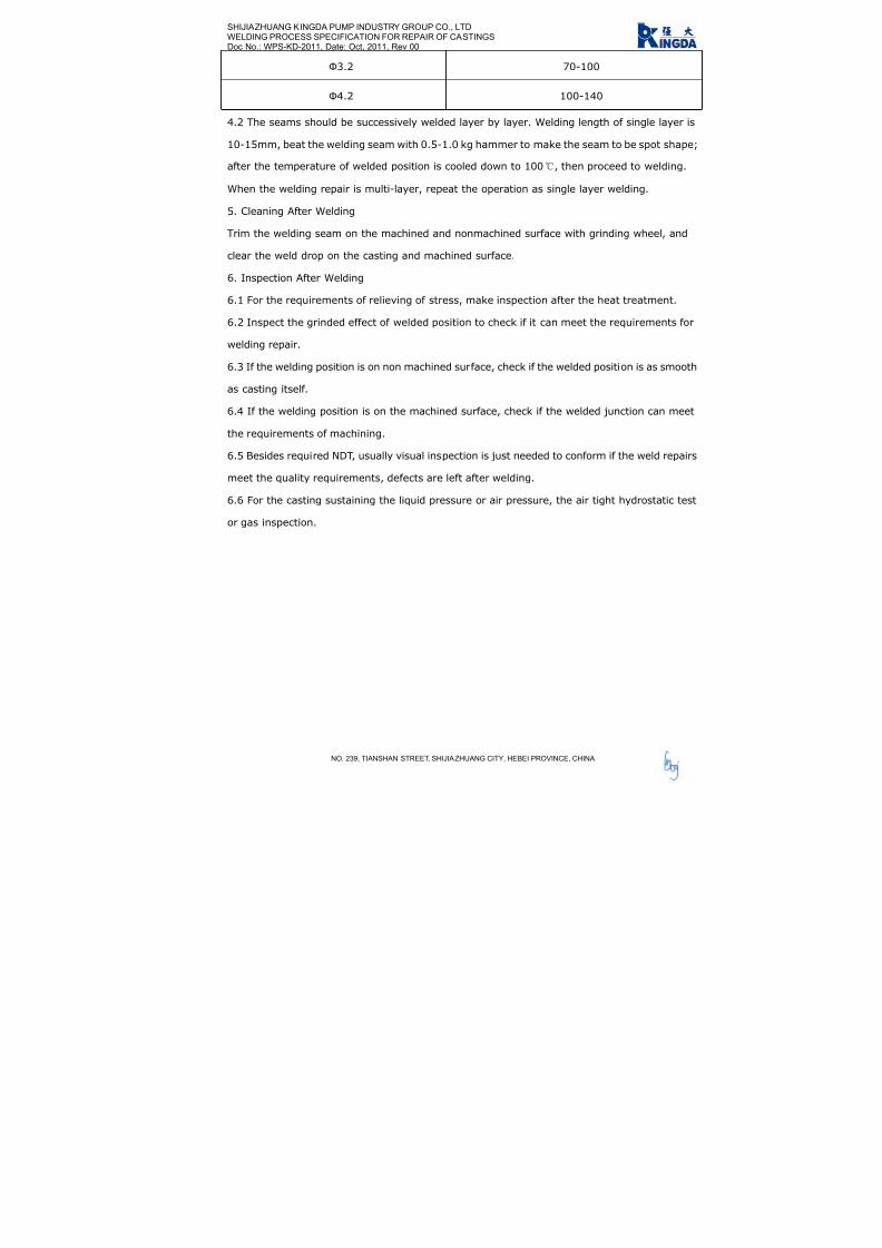
7/17/2019 R05323-P-001A-X009-0042.pdf
http://slidepdf.com/reader/full/r05323-p-001a-x009-0042pdf 255/463
SHIJIAZHUANG KINGDA PUMP INDUSTRY GROUP CO., LTD
WELDING PROCESS SPECIFICATION FOR REPAIR OF CASTINGS
Doc No.: WPS-KD-2011, Date: Oct, 2011, Rev 00
NO. 239, TIANSHAN STREET, SHIJIAZHUANG CITY, HEBEI PROVINCE, CHINA
Ф3.2 70-100
Ф4.2 100-140
4.2 The seams should be successively welded layer by layer. Welding length of single layer is
10-15mm, beat the welding seam with 0.5-1.0 kg hammer to make the seam to be spot shape;
after the temperature of welded position is cooled down to 100, then proceed to welding.
When the welding repair is multi-layer, repeat the operation as single layer welding.
5. Cleaning After Welding
Trim the welding seam on the machined and nonmachined surface with grinding wheel, and
clear the weld drop on the casting and machined surface.
6. Inspection After Welding
6.1 For the requirements of relieving of stress, make inspection after the heat treatment.
6.2 Inspect the grinded effect of welded position to check if it can meet the requirements for
welding repair.
6.3 If the welding position is on non machined surface, check if the welded position is as smooth
as casting itself.
6.4 If the welding position is on the machined surface, check if the welded junction can meet
the requirements of machining.
6.5 Besides required NDT, usually visual inspection is just needed to conform if the weld repairs
meet the quality requirements, defects are left after welding.
6.6 For the casting sustaining the liquid pressure or air pressure, the air tight hydrostatic test
or gas inspection.

7/17/2019 R05323-P-001A-X009-0042.pdf
http://slidepdf.com/reader/full/r05323-p-001a-x009-0042pdf 256/463

7/17/2019 R05323-P-001A-X009-0042.pdf
http://slidepdf.com/reader/full/r05323-p-001a-x009-0042pdf 257/463

7/17/2019 R05323-P-001A-X009-0042.pdf
http://slidepdf.com/reader/full/r05323-p-001a-x009-0042pdf 258/463

7/17/2019 R05323-P-001A-X009-0042.pdf
http://slidepdf.com/reader/full/r05323-p-001a-x009-0042pdf 259/463

7/17/2019 R05323-P-001A-X009-0042.pdf
http://slidepdf.com/reader/full/r05323-p-001a-x009-0042pdf 260/463

7/17/2019 R05323-P-001A-X009-0042.pdf
http://slidepdf.com/reader/full/r05323-p-001a-x009-0042pdf 261/463

7/17/2019 R05323-P-001A-X009-0042.pdf
http://slidepdf.com/reader/full/r05323-p-001a-x009-0042pdf 262/463

7/17/2019 R05323-P-001A-X009-0042.pdf
http://slidepdf.com/reader/full/r05323-p-001a-x009-0042pdf 263/463
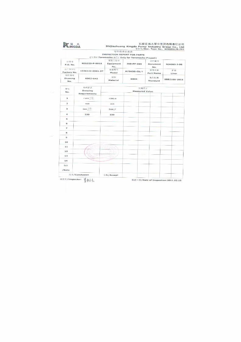
7/17/2019 R05323-P-001A-X009-0042.pdf
http://slidepdf.com/reader/full/r05323-p-001a-x009-0042pdf 264/463

7/17/2019 R05323-P-001A-X009-0042.pdf
http://slidepdf.com/reader/full/r05323-p-001a-x009-0042pdf 265/463

7/17/2019 R05323-P-001A-X009-0042.pdf
http://slidepdf.com/reader/full/r05323-p-001a-x009-0042pdf 266/463

7/17/2019 R05323-P-001A-X009-0042.pdf
http://slidepdf.com/reader/full/r05323-p-001a-x009-0042pdf 267/463

7/17/2019 R05323-P-001A-X009-0042.pdf
http://slidepdf.com/reader/full/r05323-p-001a-x009-0042pdf 268/463
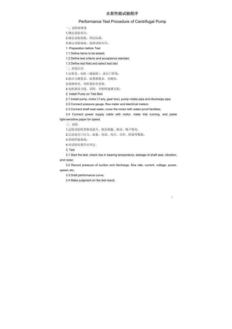
7/17/2019 R05323-P-001A-X009-0042.pdf
http://slidepdf.com/reader/full/r05323-p-001a-x009-0042pdf 269/463
1
水泵 能试验程
Performance Test Procedure of Centrifugal Pump
一、试验前准备
1.确定试验项目;
2.确定试验依据、判定标准;
3.确定试验场地、选择试验台位;
1. Preparation before Test
1.1 Define items to be tested;
1.2 Define test criteria and acceptance standard
1.3 Define test field and select test bed
二、组装台位
1.安装泵、电机(减速机)、进出口管线; 2.接压力测量表、流量测量表、电测表;
3.接轴封水,电机装防水设备;
4.电机接动力线,试转,并贴转速感光纸;
2. Install Pump on Test Bed
2.1 Install pump, motor (if any, gear box), pump intake pipe and discharge pipe;
2.2 Connect pressure gauge, flow meter and electrical meters;
2.3 Connect shaft seal water, cover the motor with water-proof facilities;
2.4 Connect power supply cable with motor, make trial running, and paste
light-sensitive paper for speed.
三、试验
1.运转试验检查轴承温升、轴封泄漏、振动、噪声情况;
2.记录进出口压力、流量、电流、电压、功率、转速等数据;
3.绘制性能曲线;
4.对试验结果作出判定。
3. Test
3.1 Start the test, check rise in bearing temperature, leakage of shaft seal, vibration,
and noise;
3.2 Record pressure of suction and discharge, flow rate, current, voltage, power,
speed, etc;
3.3 Draft performance curve;
3.4 Make judgment on the test result.

7/17/2019 R05323-P-001A-X009-0042.pdf
http://slidepdf.com/reader/full/r05323-p-001a-x009-0042pdf 270/463

7/17/2019 R05323-P-001A-X009-0042.pdf
http://slidepdf.com/reader/full/r05323-p-001a-x009-0042pdf 271/463

7/17/2019 R05323-P-001A-X009-0042.pdf
http://slidepdf.com/reader/full/r05323-p-001a-x009-0042pdf 272/463
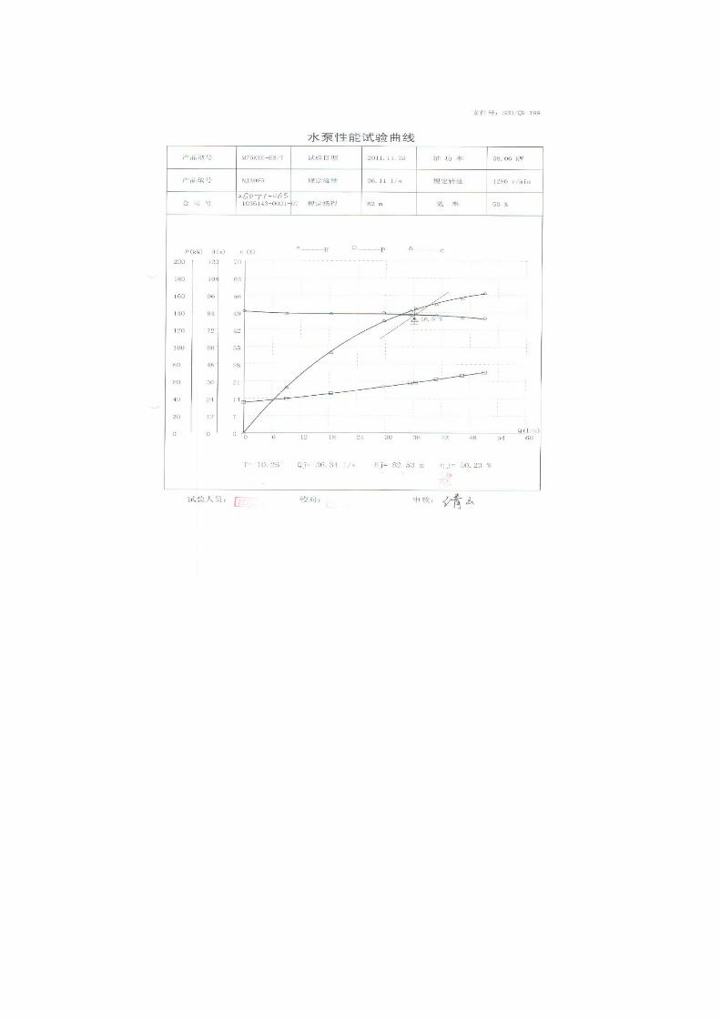
7/17/2019 R05323-P-001A-X009-0042.pdf
http://slidepdf.com/reader/full/r05323-p-001a-x009-0042pdf 273/463

7/17/2019 R05323-P-001A-X009-0042.pdf
http://slidepdf.com/reader/full/r05323-p-001a-x009-0042pdf 274/463

7/17/2019 R05323-P-001A-X009-0042.pdf
http://slidepdf.com/reader/full/r05323-p-001a-x009-0042pdf 275/463

7/17/2019 R05323-P-001A-X009-0042.pdf
http://slidepdf.com/reader/full/r05323-p-001a-x009-0042pdf 276/463
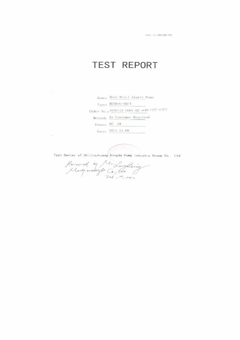
7/17/2019 R05323-P-001A-X009-0042.pdf
http://slidepdf.com/reader/full/r05323-p-001a-x009-0042pdf 277/463

7/17/2019 R05323-P-001A-X009-0042.pdf
http://slidepdf.com/reader/full/r05323-p-001a-x009-0042pdf 278/463

7/17/2019 R05323-P-001A-X009-0042.pdf
http://slidepdf.com/reader/full/r05323-p-001a-x009-0042pdf 279/463

7/17/2019 R05323-P-001A-X009-0042.pdf
http://slidepdf.com/reader/full/r05323-p-001a-x009-0042pdf 280/463
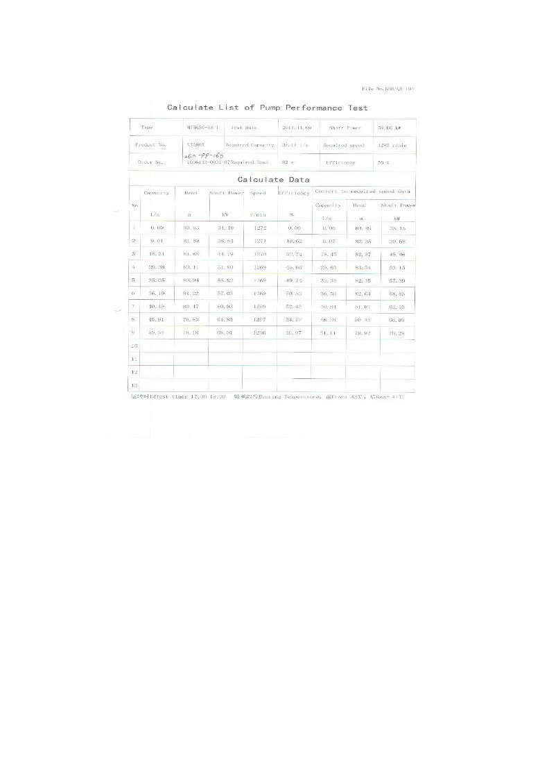
7/17/2019 R05323-P-001A-X009-0042.pdf
http://slidepdf.com/reader/full/r05323-p-001a-x009-0042pdf 281/463

7/17/2019 R05323-P-001A-X009-0042.pdf
http://slidepdf.com/reader/full/r05323-p-001a-x009-0042pdf 282/463

7/17/2019 R05323-P-001A-X009-0042.pdf
http://slidepdf.com/reader/full/r05323-p-001a-x009-0042pdf 283/463

7/17/2019 R05323-P-001A-X009-0042.pdf
http://slidepdf.com/reader/full/r05323-p-001a-x009-0042pdf 284/463

7/17/2019 R05323-P-001A-X009-0042.pdf
http://slidepdf.com/reader/full/r05323-p-001a-x009-0042pdf 285/463

7/17/2019 R05323-P-001A-X009-0042.pdf
http://slidepdf.com/reader/full/r05323-p-001a-x009-0042pdf 286/463
性能试验 息表
Test Details Sheet
1 泵 息/ Pump Details
订单号
P.O. No.:
R05323-P-001A 设备工位号
Equipment No.
260-PP-065 文件编号
Doc. No.
NJA065
强大合同号
Kingda Contract No.
1036143-0001-07 泵型号
Pump Model
M75KSG-EB/T
2 电机 息/Motor Details
制造者
Make
WEG 电机编号
Serial No.
1010904701 电机工位号
Motor No.
260-PP-065-M1
电机型号
Motor Model
447T 电机等级
Motor Rating
90KW 电机转速
Motor Speed
1780
3 试验 息/Test Details
测试开始时间
Pump Started
17:30 测试结束时间
Pump Stopped
18:30 试验日期
Test Date
2011.11.09
轴承温度
Bearing Temp.
43 环境温度
Ambient Temp.
19 水温
Water Temp.
19
4 试验性能参数 证/Performance Test Data Tolerance & Standard
参数名称/Parameter 流量/Flow 扬程/Head 效率/Efficiency 标准依据/Standard: ANSI/HI 1.6-B
5机械运行公差
Mechanical Run Tolerance & Standard
5.1 振动/Vibration 标准依据/Standard: JB/T8097-1999
5.2 噪声级别/Noise Level
参考合同规范/As per Order Spec.: 最大 85dbA/Max 85
dB(A)
5.3 温升标准/Rise in Temp. Acceptance
标准依据/Standard: JB/T8096-1998
测试后温度 /Measured Temp.

7/17/2019 R05323-P-001A-X009-0042.pdf
http://slidepdf.com/reader/full/r05323-p-001a-x009-0042pdf 287/463
SERIES (M/R) KSH/KSG SLURRY PUMP
INSTALLATION, OPERATION AND MAINTENANCE
MANUAL
SHIJIAZHUANG KINGDA PUMP INDUSTRY GROUP CO.,LTD
2010

7/17/2019 R05323-P-001A-X009-0042.pdf
http://slidepdf.com/reader/full/r05323-p-001a-x009-0042pdf 288/463
Series (M/R) KSH/KSG Slurry PumpInstallation, Operation & Maintenance Manual
Shijiazhuang Kingda Pump Industry Group Co.,Ltd
1
Content
1. General Introduction…………………………….……………………………….…..2
2. Construction…………………………….…………………………………………………3
3. Installation…………………………………………………………………………………..6
4. Operation………………………………………………………………………….……….12
5. Maintenance……………………………………………………………………………….17
6. Possible Failures, Cause and Solutions……………………………….…………..20

7/17/2019 R05323-P-001A-X009-0042.pdf
http://slidepdf.com/reader/full/r05323-p-001a-x009-0042pdf 289/463
Series (M/R) KSH/KSG Slurry PumpInstallation, Operation & Maintenance Manual
Shijiazhuang Kingda Pump Industry Group Co.,Ltd
1 . GENERAL I N TRODUCT I ON
Series (M/R) KSH/KSG Pump is also called “High Efficiency Slurry Pump”. Because these pumps
are fitted with thick wear-resistant parts and heavy frame, so they are suitable to pump the slurry
of highly abrasion, high or low content and high head. During the max permissible working
pressure range, these pumps can be operated in serial. They also can transport the corrosive
slurries.
TYPE DEMONSTRATION:
2
Frame Type/Lubrication Type
Pump Type
Pump Discharge Diameter. (mm)
Metal Lined/Rubber Lined
Example: M200KSH (/KSG)-FA (/B)
M/R M for Metal Liner, R for Rubber Liner
200 Discharge Diameter is 200 mm
KSH Kingda Heavy-duty Slurry Pump
KSG Kingda High-head Slurry Pump
F Frame Type
A/B A for oil lubrication, B for grease lubrication

7/17/2019 R05323-P-001A-X009-0042.pdf
http://slidepdf.com/reader/full/r05323-p-001a-x009-0042pdf 290/463
Series (M/R) KSH/KSG Slurry PumpInstallation, Operation & Maintenance Manual
Shijiazhuang Kingda Pump Industry Group Co.,Ltd
2 . CONSTRUCT I ON
2.1 Pump Head (See Figure 1 and Figure 2)
Both Series (M/R) KSH/KSG metal-lined and rubber-lined pump have construction of
double-casing. They have the replaceable wear-resistant metal liner or rubber liner (including the
impeller, liner, frame plate, etc). Pump casing and cover are made of ductile cast iron; their
construction is vertically split and connected with the bolts. The casing is connected with the
frame with the bolt. When the suction of the pump is installed horizontally, the discharge can be
orientated in any 8 positions at 45° intervals. The front and rear cover plates of impeller have the
back vanes to decrease the leakage and raise the service life of the pumps. Viewing the pump
from the drive side, it should rotate clockwise.
Figure 1 Construction Drawing of MKSH/MKSG (Metal-lined)
Discharge diameter<40mm, open type impeller; Discharge diameter>40mm, enclosed type impeller.
1 Frame 2 Pump Cover 3 Cover Plate 4 Impeller
5 Liner 6 Pump Casing 7 Frame Plate 8 Packing Box
3

7/17/2019 R05323-P-001A-X009-0042.pdf
http://slidepdf.com/reader/full/r05323-p-001a-x009-0042pdf 291/463
Series (M/R) KSH/KSG Slurry PumpInstallation, Operation & Maintenance Manual
Shijiazhuang Kingda Pump Industry Group Co.,Ltd
Figure 2 Construction Drawing of RKSH/RKSG (Rubber-lined)
Discharge diameter<40mm, open type impeller; Discharge diameter>40mm, enclosed type impeller.
1 Frame 2 Pump Cover 3 Cover Plate (R) 4 Impeller
5 Cover Liner 6 Pump Casing 7 Frame Liner 8 Packing Box
2.2 Shaft Seal
There three types of shaft seals, packing seal, expeller seal and mechanical seal.
(1) Packing Seal: simple construction and easy maintenance. Shaft seal water is required. For the
condition which does not need the expeller seal, the packing seal can be used.
(2) Expeller Seal: Expeller seal can be used on the single stage pump or the first stage pump in
serial when the suction positive pressure is not more than the discharge pressure by 10%. The
expeller seal does not require the shaft seal water, and the slurry will not be diluted, which can
reach good sealing effect.
(3) Mechanical Seal: Mechanical seal features for highly wear resistant and shock resistance. It
can get non-leak sealing effect under various bad conditions, and be easily installed and
4

7/17/2019 R05323-P-001A-X009-0042.pdf
http://slidepdf.com/reader/full/r05323-p-001a-x009-0042pdf 292/463
Series (M/R) KSH/KSG Slurry PumpInstallation, Operation & Maintenance Manual
Shijiazhuang Kingda Pump Industry Group Co.,Ltd
5
replaced.
2.3 Transmission Part
During the bearing assembly of (M/R) KSH/KSG Pump, the pump has large diameter, high
stiffness and short cantilever, which will not bend and vibrate under the bad working conditions.
According to the different transmitted power, heavy single-row or double-row tapered roller
bearings can be selected. These bearings can stand the max axial and radial load of the pump. Oil
lubrication is used for the bearing. Seal cover, labyrinth bush, water-proof cover and guard cover
are fitted at the both sides of the bearing body, to prevent the impurities and water from entering
into the bearing and ensure the normal and safe operation of the bearing.
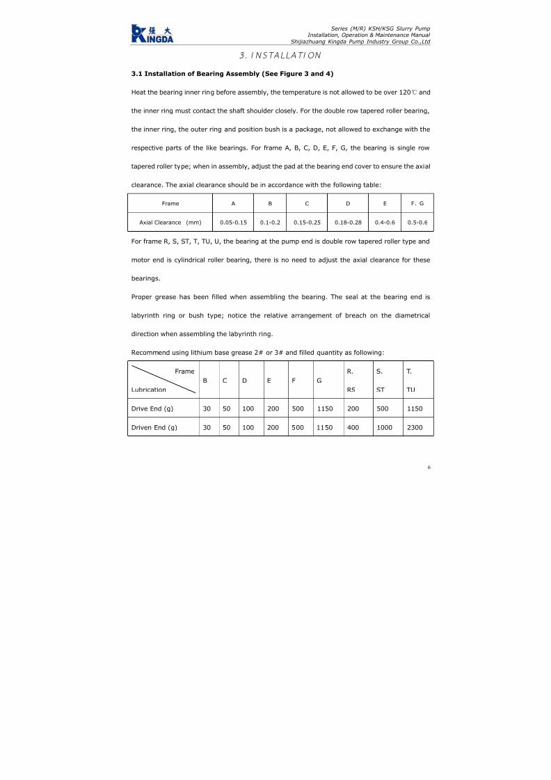
7/17/2019 R05323-P-001A-X009-0042.pdf
http://slidepdf.com/reader/full/r05323-p-001a-x009-0042pdf 293/463
Series (M/R) KSH/KSG Slurry PumpInstallation, Operation & Maintenance Manual
Shijiazhuang Kingda Pump Industry Group Co.,Ltd
3 . I N ST A LL AT I ON
3.1 Installation of Bearing Assembly (See Figure 3 and 4)
Heat the bearing inner ring before assembly, the temperature is not allowed to be over 120 and
the inner ring must contact the shaft shoulder closely. For the double row tapered roller bearing,
the inner ring, the outer ring and position bush is a package, not allowed to exchange with the
respective parts of the like bearings. For frame A, B, C, D, E, F, G, the bearing is single row
tapered roller type; when in assembly, adjust the pad at the bearing end cover to ensure the axial
clearance. The axial clearance should be in accordance with the following table:
Frame A B C D E F、G
Axial Clearance (mm) 0.05-0.15 0.1-0.2 0.15-0.25 0.18-0.28 0.4-0.6 0.5-0.6
For frame R, S, ST, T, TU, U, the bearing at the pump end is double row tapered roller type and
motor end is cylindrical roller bearing, there is no need to adjust the axial clearance for these
bearings.
Proper grease has been filled when assembling the bearing. The seal at the bearing end is
labyrinth ring or bush type; notice the relative arrangement of breach on the diametrical
direction when assembling the labyrinth ring.
Recommend using lithium base grease 2# or 3# and filled quantity as following:
Frame
Lubrication
B C D E F G
R.
RS
S.
ST
T.
TU
Drive End (g) 30 50 100 200 500 1150 200 500 1150
Driven End (g) 30 50 100 200 500 1150 400 1000 2300
6

7/17/2019 R05323-P-001A-X009-0042.pdf
http://slidepdf.com/reader/full/r05323-p-001a-x009-0042pdf 294/463
Series (M/R) KSH/KSG Slurry PumpInstallation, Operation & Maintenance Manual
Shijiazhuang Kingda Pump Industry Group Co.,Ltd
Figure 3 Constructions Drawing of R, S, ST, TU, T, U Frame Bearing Assembly
1 Labyrinth Bush 2 Oil Cup 3 Bearing Body 4 Bearing
5 End Cover 6 End Cover Seal Pad 7 Shaft
Figure 4 Construction Drawing of A,B,C,D,E,F,G Frame Bearing Assembly
1 Labyrinth Bush 2 Oil Cup 3 Grease Blocker 4 Bearing Body
5 Bearing 6 Adjusting Pad 7 End Cover 8 Shaft
3.2 Installation of Shaft Packing Seal
Shaft packing seal assembly includes packing box, shaft sleeve, position bush, seal ring, packing,
packing pad, lantern ring, front lantern ring and packing gland. Packing seal assembly is divided
into lantern ring structure and front lantern ring structure. Front lantern ring structure is the
standard-installed type, and you can see Figure 5 (1) and Figure 5 (2) for the installation drawing.
Lantern ring structure should be used for the condition of suction, for example of installation way
7

7/17/2019 R05323-P-001A-X009-0042.pdf
http://slidepdf.com/reader/full/r05323-p-001a-x009-0042pdf 295/463
Series (M/R) KSH/KSG Slurry PumpInstallation, Operation & Maintenance Manual
Shijiazhuang Kingda Pump Industry Group Co.,Ltd
in Figure 6 (1) and (2). Take notice that the seal ring must be in the right position between shaft
sleeve and position bush, and the shaft sleeve and impeller.
Figure 5 (1) and Figure 6 (1) are the construction drawing for the pump of discharge diameter
less than 150mm;
Figure 5 (2) and Figure 6 (2) are the construction drawing for the pump of discharge diameter
more than 500mm.
Selection of the packing: when the working pressure of the pump is below 1MPa (10kgf/cm2),
asbestos fibers dip mica packing is usually used; asbestos fibers soaked PTFE packing is usually
used when the pressure is higher than 1MPa (10kgf/cm2) or pumping the corrosive slurry.
Figure 5(1) Packing Seal Construction
Standard Type
Figure 6(1) Packing Seal Construction
For Suction-Up Condition
1 Shaft Sleeve 2 Packing 1 Shaft Sleeve 2 Packing
3 Packing Box 4 Front Lantern Ring 3 Packing Box 4 Lantern Ring
5 Seal Ring 6 Locating Bush 5 Seal Ring 6 Locating Bush
7 Packing Pad
8

7/17/2019 R05323-P-001A-X009-0042.pdf
http://slidepdf.com/reader/full/r05323-p-001a-x009-0042pdf 296/463
Series (M/R) KSH/KSG Slurry PumpInstallation, Operation & Maintenance Manual
Shijiazhuang Kingda Pump Industry Group Co.,Ltd
9
Figure 5(2) Packing Seal Construction
Standard Type
Figure 6(2) Packing Seal Construction
For Suction-Up Condition
1 Shaft Sleeve 2 Packing 1 Shaft Sleeve 2 Packing
3 Packing Box 4 Front Lantern Ring 3 Packing Box 4 Lantern Ring
5 Packing Pad
3.3 Installation of Expeller Seal
Expeller seal assembly includes expeller, release cover shaft sleeve, lantern ring, packing pad,
packing, packing gland, etc. Every part must be installed at right position as in Figure 7.
Figure 7 Seal Construction of Expeller
1 Packing Gland 2 Release Cover 3 Expeller 4 Shaft Sleeve

7/17/2019 R05323-P-001A-X009-0042.pdf
http://slidepdf.com/reader/full/r05323-p-001a-x009-0042pdf 297/463
Series (M/R) KSH/KSG Slurry PumpInstallation, Operation & Maintenance Manual
Shijiazhuang Kingda Pump Industry Group Co.,Ltd
5 Seal Ring 6 Packing 7 Lantern Ring 8 Packing Pad
3.4 Installation of Mechanical Seal
Mechanical seal assembly includes Cartridge type mechanical seal, seal box, seal ring, etc.
Strictly install the mechanical seal according to the Manual. See Figure 8 for construction.
Figure 8 Construction of Mechanical Seal
1 Seal Box 2 Seal Ring 3 Mechanical Seal
3.5 Installation of Pump Head
Firstly fit the pump body on the frame, then put the shaft seal assembly into the pump body; fit
the rear guard plate and impeller with rear hanging pipe and rear set nut; fit the liner with the
hanging beam and use the bolts to press the liner against the pump body; fit the front guard the
plate into the pump cover, bolt the pump cover, front plate together with the pump body and
fasten all the bolts and nuts. For rubber liner pump, the front liner should be firstly put into the
pump cover and fasten the bolts, then assembly the pump body and pump cover; coat the soapy
water and rubber lubricant at the contact surface for the easy assembly; take notice that the seal
pads should be put at the right position and compressed; to assure the correct position and easy
assembly, the rear guard plate and rear liner hang pipe *302, rear guard plate and rear liner
position nut *302 and liner hanging beam *304 can be used. Following Figures show the
10

7/17/2019 R05323-P-001A-X009-0042.pdf
http://slidepdf.com/reader/full/r05323-p-001a-x009-0042pdf 298/463
Series (M/R) KSH/KSG Slurry PumpInstallation, Operation & Maintenance Manual
Shijiazhuang Kingda Pump Industry Group Co.,Ltd
methods.
The pump with ST, T and TU has release ring; before dismantling, the three hex bolts should be
removed and screw them into thither bolt hole on the release ring to jack the three pressure pad
on the shaft to loose the impeller.
Figure 9
1. Rear Guard Plate and Rear Liner Hang Pipe x302
2. Rear Guard Plate and Rear Liner Setting Nut x303
3. Liner Hang Beam x304
11

7/17/2019 R05323-P-001A-X009-0042.pdf
http://slidepdf.com/reader/full/r05323-p-001a-x009-0042pdf 299/463
Series (M/R) KSH/KSG Slurry PumpInstallation, Operation & Maintenance Manual
Shijiazhuang Kingda Pump Industry Group Co.,Ltd
12
4 . OPERAT I ON
4.1 Startup
Check the whole machine unit as following procedure before start up:
(1): The pump should be installed on the solid base to bear the whole pump weight to absorb the
vibration and fasten all the foundation bolts.
(2): The pipeline and valves should be separately supported. There is seal pad at the pump flange.
Notice that the pump metal liner may be higher than flange surface when fastening the bolts, and
the bolts should be not over-fastened to avoid damaging the seal pad.
(3): Rotate the pump shaft in accordance with the pump rotation direction, the shaft should drive
the impeller without the friction; if not, the impeller clearance should be adjusted.
(4): Check the motor rotation direction to make sure it can drive the pump rotate toward the
arrow. Reverse rotation may cause the impeller screw stripped and damage the pump, so it’s
forbidden.
(5): For direct coupling drive, the pump shaft and motor shaft should be strictly centered. The
pump shaft and motor shaft should be in parallel for the belt transmission and adjust the pulley
position to make it vertical to the belt. For the pulley unit of SPA Type andSPA
SPB Type, SPB Type
andSPB
SPC Type, the adjustment of the pulley should reach the requirements of α1=α2 in Figure 10.
(6): A short removable pipe should be fit at the suction of the pump, its length is enough to
disassemble the pump cover, replace the wearing parts and inspect the pump. See the Outline
Dimensional Drawing for the length of this short pipe.
(7): Check shaft seal: for the pumps of expeller seal, when the oil cup is fit with the release gland,
the lubricating grease should be filled through the oil cup; and Sodium-calcium grease is

7/17/2019 R05323-P-001A-X009-0042.pdf
http://slidepdf.com/reader/full/r05323-p-001a-x009-0042pdf 300/463
Series (M/R) KSH/KSG Slurry PumpInstallation, Operation & Maintenance Manual
Shijiazhuang Kingda Pump Industry Group Co.,Ltd
recommended.
For the pumps of packing seal, firstly turn on the shaft sealing water system to check if the water
quantity and pressure is proper before the startup of the pump; adjust the packing gland set
screw to regulate the tension of the packing; adjust shaft seal water (that the leak quantity at the
packing gland is drop by drop); if too tight, the shaft sleeve will heat easily and power will be
consumed more; if too loose, the leak quantity will be very large. The shaft seal water pressure
usually is higher than pump discharge pressure by 3.5X10⁻²MPa (0.35kgf/cm2). See following
table for shaft seal water quantity:
Frame Type A B C D E.F G R.RS S.ST T.TU U
Shaft Seal Water Quantity (L/s) 0.15 0.25 0.35 0.55 0.70 1.2 0.70 1.2 1.6 2.1
(8) Adjustment for the Belt Pretightening Force
We recommend following method for reference:
(8.1) First calculate thee pretightening force Q:
Q=2
1
21 )5.2(510mv
V Z C
C PC +
××
×− (Newton)
(8.2) Then find the e value on the curve according to the pretightening force and belt type;
(8.3) Find f through formula f=e
.
L’
100 ;
(8.4) Find R value of respective V-belt in Table 1, and adjust the center distance of both pulleys
according to the methods in Figure 11 to reach the required pretightening force. Usually, if the
overall reduction is no more than f when loading the Newton force, it reaches the required
pretightening force Q.
In the formula:
Q: the minimum pretightening force of each belt in the static state, unit is Newton;
13

7/17/2019 R05323-P-001A-X009-0042.pdf
http://slidepdf.com/reader/full/r05323-p-001a-x009-0042pdf 301/463
Series (M/R) KSH/KSG Slurry PumpInstallation, Operation & Maintenance Manual
Shijiazhuang Kingda Pump Industry Group Co.,Ltd
f: Overall reduction of belt, unit is mm
C1: Angle coefficient is about 0.9
C2: Operation coefficient is about 1.4
L′: Center distance of pulleys
P: Motor Rated Power, KW
Z: V-Belt Quantity
V: linear velocity, m/s
m: Centrifugal force coefficient (see Figure 1)
e: Reduction e of each 100mm hang length, see Figure 11.
Table 1
Type SPA SPB SPC SPZ
R (N) 60 90 120 30
m 0.12 0.20 0.38 0.08
Adjust the V-belt till the final pretightening force is the minimum when the load is at max; when
several belts are used at the same time, the circumference of each belt should be basically the
same to assure the equal force.
Figure 10
14

7/17/2019 R05323-P-001A-X009-0042.pdf
http://slidepdf.com/reader/full/r05323-p-001a-x009-0042pdf 302/463
Series (M/R) KSH/KSG Slurry PumpInstallation, Operation & Maintenance Manual
Shijiazhuang Kingda Pump Industry Group Co.,Ltd
Figure 11
After adjustment of the V-belt, check if the impeller can rotate normally again; if possible, start
the pump with clear water (before it begins to pump the slurry); turn on the suction pipe valve,
start the motor, check the pressure and flow quantity at the suction and discharge, check the
leakage at the packing. If the packing heats, loose the packing gland bolts to make the leakage
bigger; adjust the leakage to the specified value till the packing run-in with the shaft.
4.2 Operation
(1): Periodically check the pressure and flow quantity of shaft seal water, and adjust the packing
gland and replace the packing during the operation to assure small quantity of clean water
passing through the shaft.
15

7/17/2019 R05323-P-001A-X009-0042.pdf
http://slidepdf.com/reader/full/r05323-p-001a-x009-0042pdf 303/463
Series (M/R) KSH/KSG Slurry PumpInstallation, Operation & Maintenance Manual
Shijiazhuang Kingda Pump Industry Group Co.,Ltd
16
(2): Periodically check the frame. If the bearing heats at the beginning of the operation, shut
down the pump till the bearing become cool, then run it. If the bearing heats seriously and
temperature keep rising, the frame must be disassembled and examined for the cause. Usually
the impurity contained in the lubricating oil can cause the heating, so the bearing oil should be
proper and clean, and replaced periodically.
(3): The pump performance will become poorer and the efficiency will become lower with the
larger and larger clearance between impeller and front guard plate. So adjust the impeller timely
to keep the proper clearance to make the pump run in high efficiency. When the wear situation of
the pump is too bad to meet the requirements of the system, the wear parts should be replaced.
4.3 Shutdown of Pump
Let the pump to transport the clear water for some before the shutdown to clean the slurry left
inside the pump, then stop the pump, valve, packing seal water or mechanical seal water in order.

7/17/2019 R05323-P-001A-X009-0042.pdf
http://slidepdf.com/reader/full/r05323-p-001a-x009-0042pdf 304/463
Series (M/R) KSH/KSG Slurry PumpInstallation, Operation & Maintenance Manual
Shijiazhuang Kingda Pump Industry Group Co.,Ltd
17
5 . MA I NTENAN CE
For the safe run of pump, attention must be paid to the normal maintenance as following aspects:
5.1 Maintenance of shaft seal:
For the packing seal pump, periodically check the water pressure and water quantity of shaft
packing seal. Always keep small quantity of clear water flow along with the shaft, periodically
adjust the packing gland, check and replace the packing. The shaft seal water pressure and
quantity should in accordance with the above requirements. Periodically fill the oil into the oil cup
for the expeller seal pump to lubricate the inside packing.
5.2 Adjustment of impeller:
To assure the high-efficiency of the pump, the clearance between the impeller and the front guard
plate; the clearance between impeller and front guard plate of metal liner pump should be
0.5-1mm, the clearance between the impeller and front liner should be equal to that between
impeller and rear liner.
Before adjusting the clearance, the pump should be stopped firstly, then loose the bolts of
bearing assembly and screw the nut of adjusting bolts to make the bearing assembly move
forward, at the same time, rotate the pump as per the arrow by hands till the impeller friction
with the front guard plate; for the metal liner pump, loose the nut (which was fastened) by half
circle, then fasten the nut on the adjusting bolt to make the bearing assembly move backward,
the clearance between the impeller and front guard plate should be 0.5-1mm; for the rubber liner
pump, adjust the nut of the adjusting bolts to make the bearing assembly to move forward to
contact with the front guard sleeve, then move the bearing assembly back to contact with the
back liner, and measure the total movement distance, make the half of this distance as the

7/17/2019 R05323-P-001A-X009-0042.pdf
http://slidepdf.com/reader/full/r05323-p-001a-x009-0042pdf 305/463
Series (M/R) KSH/KSG Slurry PumpInstallation, Operation & Maintenance Manual
Shijiazhuang Kingda Pump Industry Group Co.,Ltd
18
clearance of the impeller and front liner; assure the correct clearance of impeller and front and
back liner by adjusting bearing assembly position through the adjusting bolts.
After the adjustment, check if the impeller can rotate normally before startup, if bearing
assembly compress bolts and adjusting bolts are tightened; then start the pump.
5.3 Lubricating of Bearing
Correct assembly, proper lubricating and in-time maintenance will make the service life of
bearing assembly longer. Periodically check the bearing assembly, bearing and lubricant and
interval should not be over than 12 month. Fill the lubricating grease at regular intervals in
operation, the filling interval and filling quantity are relative to the pump speed, bearing size,
continuous operation time, shutdown and startup times, environmental condition and
temperatures; excess grease will cause the heating of bearing. Refer to following table for proper
lubricating schedule:
5.4 Standby pump should be rotated by 1/4 circle by hands to make the bearing stand static load
and vibration evenly

7/17/2019 R05323-P-001A-X009-0042.pdf
http://slidepdf.com/reader/full/r05323-p-001a-x009-0042pdf 306/463
Series (M/R) KSH/KSG Slurry PumpInstallation, Operation & Maintenance Manual
Shijiazhuang Kingda Pump Industry Group Co.,Ltd
Lubrication Schedule (in hours)
19
Note: Above Schedule is only applied for the normal working condition.
During the bearing assembly, the internal plug is to fill the bearing grease, and the external oil
cup is to clean the labyrinth seal. Besides the regular filling of grease, it’s also to fill the grease to
the oil cup to keep the labyrinth seal clean.
Bearing Speed (rpm)Frame
Type
Grease
Quantity 200 300 400 600 800 1000 1200 1800 2000
B 12 3000 2400 1800 1500 1000
C 18 3600 2400 1800 1600 1200 900
D 28 2500 2000 1500 1200 800 500
E 44 5000 3600 2200 1600 1100 800 500
F 71 7000 4200 2000 1800 1200 700 400
R.RS 102 3000 2000 1400 1000 600 400 100
S.ST 132 3800 28000 1500 900 500 300
T.TU 304 4800 3000 1800 900 400
Pump
End
U 621 4000 2400 1500 500
R.RS 61 8000 4800 3500 2800 2200 1500 900
S.ST 74 8000 6000 3600 2400 1600 1200
T.TU 133 8000 7000 4500 2500 1500
Motor
End
U 192 7000 6000 4000 2000

7/17/2019 R05323-P-001A-X009-0042.pdf
http://slidepdf.com/reader/full/r05323-p-001a-x009-0042pdf 307/463
Series (M/R) KSH/KSG Slurry PumpInstallation, Operation & Maintenance Manual
Shijiazhuang Kingda Pump Industry Group Co.,Ltd
20
6 . POSS I B LE FA I LURES , CAUSE AN D SOLUT I ONS
Failure Cause Solutions
Leak at the suction pipe or packing Block the leak
Wrong rotation direction Change the rotation direction
Impeller is broken Replace the new impeller
Not pump the liquid
Suction pipe is blocked Remove the block
Packing gland is to tight and packing heats Loose the packing gland bolts
Friction inside the pump Adjust the clearance
Bearing is broken Replace the bearing
Transmission belt is too tight Adjust the belt
Too large flow quantity Adjust the pump running conditions
High rotation speed, large proportion Adjust the rotation and proportion
Shaft Power is to high
Misalignment or nonparallel of motor shaft and Adjust the motor shaft and pump shaft
Excessive or too little of bearing lubricating oil Oil quantity should be as per
Impurities is contained in the lubricating oil Replace the new lubricating oilOverheat of bearing
Bearing is broken Replace the new bearing
Misalignment or nonparallel of motor shaft and Adjust the motor shaft and pump shaft
Shaft is bent Replace a new shaft
Friction inside the pump or the imbalance of Decrease the friction and replace a new
Foreign matter inside the bearing Clean the bearing
Service life of bearing is short
Unreasonable assembly of bearing Replace the bearing or reassemble the
Serious abrasion of packing Replace the new packing
Serious abrasion of shaft sleeve Replace the new shaft sleeveSerious leakage at the packing
Seal water is not clean Replace the clean seal water
Bearing is broken Change new bearing
Impeller is not in balance Change new impeller
Air entered into suction pipe, block Remove the air and block
Uneven flow, pump empty Improve the feeding condition
Abnormal noise and excessive vibration
of pump
Bad foundation Strength the foundation

7/17/2019 R05323-P-001A-X009-0042.pdf
http://slidepdf.com/reader/full/r05323-p-001a-x009-0042pdf 308/463
INSTALLATION,OPERATION ANDMAINTENANCE
INSTRUCTION MANUALFOR INDUCTION
MOTORSFrame sizes 143/5T to 586/7
WEG EXPORTADORA S.A.
Av. Prefeito Waldemar Grubba, 300089256-900 - J aragua do Sul - SC - BRAZIL
Phone 55 (47) 3372-4000 - Fax 55 (47) 3372-4060http://www.weg.com.br
Transforming Energy into Solutions
0 2 8 0 . 1
5 1 5 / 0 3 . 2
0 0 6

7/17/2019 R05323-P-001A-X009-0042.pdf
http://slidepdf.com/reader/full/r05323-p-001a-x009-0042pdf 309/463
THIS MANUAL IS INTENDED TO SUPPLY IMPORTANT TOPICS THAT MUST BE FOLLOWED DURING
TRANSPORTATION, INSTALLATION, OPERATION AND MAINTENANCE OF WEG MOTORS. THEREFORE, WE RECOMMEND READING CAREFULLY THIS MANUALBEFORE INSTALLING AND OPERATING THE MOTOR.
TO ENSURE PHYSICAL INTEGRITY TO THE OPERATION AND MATERIAL PROTECTION, ALL
INFORMATION INCLUDED IN THIS MANUAL MUST BE STRICTLY FOLLOWED.
I
INDEX
1. HANDLI NG AND TRANSPORTATION 2. RECEIVING INSPECTION 3. STORAGE 4. INSTALLATION
4.1 - Safe ty 4.2 - Op e ra ti ng Co n di ti o ns 4.3 - Fo u nd a ti on 4.4 - D ra in H o le s 4.5 - B alan ce 4.6 - Al ig nm e nt 4.7 - C ou p li ng s 4.8 - El ec t r ic a l Co n ne c t io n 4.9 - St ar ti ng Me th o ds 4 .10 - P ro tec t i on Dev i ce
4.11 - Star t -Up 5. MAINTENANCE
5.1 - Lubrication 5.1 .1 - Mach ines wi thout Grease Nipp les 5.1.2 - Mac hines Fitted with G rease Fitting 5.1.3 - Com patibil ity of MOBIL Polirex EM
grease with other types of grease 5 .2 - A ssemb ly and D i s as semb l y
6. SPARE PARTS 7. VARIABLE FREQUENCY DRIVE MOTORS
7.1 - St an d ar d Mo t or s 7 .2 - I nv er te r Du t y Mo to r s 7 .3 - Bear in g I n su l at io n
8. ADDITIONAL INSTRUCTIONS 8 .1 - Haza rd ou s Ar ea Mo to r s
8.1 .1 - Gene ra l 8.1.2 - Instal lat ion 8.1 .3 - Chec k ing and main tenanc e 8.1.4 - Explosion Proof M otor Repairs
9. WARRANTY TERMS
Purchasing date:
Supplier’s name
Invoice/Order number:
Customer’s name and phone:
Failure description:

7/17/2019 R05323-P-001A-X009-0042.pdf
http://slidepdf.com/reader/full/r05323-p-001a-x009-0042pdf 310/463
Lifting devices, when supplied, are designed only to supportthe motor. If the motor has two lifting devices then a double chainmust be used to lift it.Lifting and lowering must be done gently without any shocks, toavoid bearing damaged.
DURING TRANSPORTATION, MOTORS FITTED WITH ROLLER OR ANGULAR CONTACT
BEARINGS ARE PROTECTED AGAINST BEARING DAMAGES WITH A SHAFT LOCKING DEVICE
MOTORS MUST NOT BE LIFTED BY THE SHAFT,
BUT BY THE EYEBOLTS SPECIFIC FOR SUCH
PURPOSE
THIS LOCKING DEVICE MUST BE USED ON ANY FURTHER MOTOR TRANSPORTATION, EVEN
WHEN THIS MEANS TO UNCOUPLE THE MOTOR FROM THE DRIVEN MACHINE
I
I
I
2. RECEIVING INSPECTION
When receiving the motor, check if any damage has occurredduring transportation.
If anything has been noticed, notify immediately the carrier, theinsurance company and WEG.Failure in giving notice to the carrier, to the insurance companyand to WEG may result in loosing product warranty.
Do not remove the existing protecting grease from the shaft end,nor the stoppers or plugs that close the terminal box holes, if any.
These protection items must be kept in place until the finalinstallation has been concluded.After being removed from the package, a complete visualinspection on the motor should be made:
1 - HANDLING AND TRANSPORTATIONFecha de compra:
Nombre del proveedor:
Número de la factura o pedido:
Nombre y número telefónico del cliente:
Descripción de la falla:

7/17/2019 R05323-P-001A-X009-0042.pdf
http://slidepdf.com/reader/full/r05323-p-001a-x009-0042pdf 311/463
If motors are not immediately installed, they must be stored indry areas, free of dust, vibrations, gases, corrosive smokes, underconstant temperature and in normal position free from othermaterials.
Motor storage temperature must remain between 41ºF (5ºC) to140ºF (60ºC), with relative humidity not exceeding 50%.
If motors are stored for more than two years, bearings must bereplaced or the lubrication grease must be totally removed aftercleaning.
Single-phase motors when kept in stock for 2 years or moremust have their capacitors replaced (if any).
WEG recommends to rotate the shaft (by hands) at least once a
month, and to measure the insulation resistance before installingit, if motors are stored for more than 6 months or when subjectto high humidity areas.
If motor is fitted with space heaters, it is recommended to switchthem on during storage period if the relative humidity exceeds50%.If motor remains in stock for a long period without having thespace heaters switched-on or when installed but not in operation,moisture/water inside the motor may condense. On these cases,water must be drained by removing the threaded drain plugs.When drainage is done, switch-on the space heaters and makesure the motor is completely dry, then reinstall the drain plugs toensure proper Degree of Protection (see figure 1).
The space heaters should NEVER be energized while motor isrunning.
3 - STORAGE
ü Check if any damage has occured during transportation.ü Check nameplate data.ü Rotate shaft with the hand to make sure it is running freely.ü Make sure the motor was not exposed to excessive dirt andmoisture during transportation and storage.
9. TERMINOS DE GARANTIA
WEG of rec e garantía co nt ra defec tos d e fabr icac ión o d e materiales para sus p roduc tos, por un p eríodo de 18 me ses,con tados a partir de la fecha de la emisión de la factura por parte de fáb rica o d el distribuidor/revendedor, teniendo c omo límite 24 meses d e la fecha de fabric ación indep endiente de la fecha de instalac ión del motor, siemp re y cuand o hayan sido sat isfechos los siguientes requis i tos:
- Transpor te , manoseo y a lmacenamiento adecuados; - I n s t a la c i ón co r r e c t a y en cond i c i o ne s amb i e n t a l e s espec íficas y sin presenc ia de g a ses corrosivos; - Operación dentro de los límites de la capacid ad del moto r; - Realización periódica del d ebido m antenimiento prevent ivo; - Realización de reparaciones y/o modif icaciones al producto original efectuada solo por los agentes autorizados de la Red de Asiste nc ia Técn ic a WEG; - Entregar el producto a l proveedor en el caso de ocurr i r una fal la c on rec lam aci ón d e g arant ía en un p eríod o m ínim o su f i c i en te p a ra iden t i f i ca r la causa d e la an oma lía y su conven ien te repa rac ión ; - Dar av iso inmed ia to a WEG, por par te de l c l ien te , de los defectos detec tados y que los mismos sean poster iormente ana l i za do s po r WEG co mo c au sado s po r de f e c t o s de fabr icac ión.La garant ía no inc luye los servicios de desmo ntaje d el moto r en las ins ta lac iones de l c l ien te , cos to s de t ranspor te de l produc to y gastos de traslado, alojamiento y alimentación del person al de Asistencia Técnic a cuand o sean solic itados p or e l c l ien te .Los ser vicio s en ga rantía serán pre stad os exc lusivam ente e n talleres d e Asistenc ia Técn ica Aut orizada WEG o en la prop ia fábric a.Se excluyen de esta gara ntía los c ompon entes c uya vida útil,en u so no rmal, sea inferior a l períod o d e ga rantía ot orga do po r WEG las repa rac ion es o subs t i t u c iones de p iezas o pro duc t os , a cr i te r io de WEG o su Asis ten c ia Técn ica Autori zada, no pro rrog ará el plazo de g arantía orig inal.La presente g arantía se limita al pro duc to entreg ado, no sien do respon sable WEG po r daños a person as, a terc eros, a o tros
equipos e instalaciones, ut i l idades que se dejen de ob tener o cu alquier otro daño eme rgente o c onsec uente.

7/17/2019 R05323-P-001A-X009-0042.pdf
http://slidepdf.com/reader/full/r05323-p-001a-x009-0042pdf 312/463
Insulation Resistance Checking
Disconnect motor from power supply before making anyinsulation resistance measurement.
To avoid electric discharge risks, discharge the terminals rightafter performing the measurement.
Measure the insulation resistance before operating the motorand/or when there is any sign of moisture in the winding.
The resistance measured at 77ºF (25ºC) must be:
Ri ≥
(20 x U) / (1000 + 2P) [MΩ](measured with a MEGGER at 500 V d.c.)where U = voltage (V); P = power (kW).
If the insulation resistance detected is less than 2 mega ohms, thewinding must be dried according to the following procedure:Warm it up in an oven at a minimum temperature of 176ºF (80ºC)increasing 41ºF (5ºC) every hour until reaching 105ºC (221ºF),remaining under this temperature for at least one hour.
Figure 1
P Las superficies de encaje de los motores a prueba de explosiónno deben ser mecanizadas y no es permitido utilizar entre ellasningún tipo de vedamiento, no descrito o suministrado por elfabricante. Los encajes deben ser solamente limpios y para evitarcorrosión o penetración de agua, los encajes pueden serengrasados con una fina manta de grasa de silicona.P Verificar si los componentes están exentos de rebabas, golpesy suciedad.P Observar si las piezas están en perfectas condiciones.P Lubricar superficialmente las guías de las tapas con aceiteprotector para facilitar el montaje.P Utilizar solamente martillo de material blando en la colocaciónde las piezas.P Verificar si todos los tornillos están bien apretados.P Utilizar sonda calibrada para verificar asiento de la caja deconexiones (menor de 0,05mm).
8.1.4 Reparos De Motores A Prueba De Explosión
El reparo de repuestos, directamente involucrados en laprotección contra riesgo de una explosión, debe ser realizadosin cualquier modificación al diseño original del motor.
Después del reparo, estos repuestos deben ser chequeados ycuando concluido, el taller de asistencia técnica debe hacer unadeclaración de todas las operaciones realizadas en el motorespecífico.
Para maiores informaciones, en México favor comunicarse a:
WEG México, S.A de C.V.Carretera J orobas-Tula Km 3.5,Mz.5, Lote 1, entre Lote 4 y 5
Fracc. Parque Indistrial Huehuetoca,Huehuetoca Estado de Méx., C.P 54680 Tel: (55) 5321-4243 y 61; Fax: (55) 5321-4262 y 94
e-mail: [email protected]

7/17/2019 R05323-P-001A-X009-0042.pdf
http://slidepdf.com/reader/full/r05323-p-001a-x009-0042pdf 313/463
Check if the stator insulation resistance remains constant withinaccepted values. If not, stator must be reimpregnated. If necessary,replace bearings and seals.
Note:
1) All drains (if any) must be removed while drying.2 - Measured the insulation resistance in ambient temperature. If different than 25ºC it should be corrected using the followingformula:
R(25°C) = [( K+25 ) / ( K + Ta )] . R (Ta)
Where:R
(25°C)insulation resistance related to 25ºC ambient temperature
K constant value 234.5 for copper T
aambient temperature where the resistance was measured
R(Ta)
resistance value measured in ambient temperature Ta
4. INSTALLATION
4.1 - Safety
All personnel involved with electrical installations, eitherhandling, lifting, operation, start up, maintenance or repair must
be well informed and updated concerning safety standards andprinciples that govern the work and carefully follow them.
For practical reasons, it is not possible to include in this Manualdetailed information that covers all constructive variables, norcovering all possible assembly, operation or maintenancealternatives.For this reason, the present Manual only includes requiredinformation that allows qualified and trained personnel to carryout the work.
If you still have further doubts about this, specially in referenceto specific product information, WEG is willing to provide suchinformation via its network of authorized service agents and/ordistributors.
In order to allow WEG to provide prompt service, within technicalstandards, the motor serial number that is available on theidentification nameplate should be supplied.
Use always appropriate tools for installation and removal.
LA INSTALACION DE MOTORES PARA AMBIENTES PELIGROSOS DEBE SER EJECUTADA POR
PERSONAL ESPECIALIZADO
LA ESPECIFICACION DEL LOCAL DE INSTALACION ES DE RESPONSABILIDAD DELCLIENTE, QUE TAMBIEN DETERMINARA LAS
CARACTERISTICAS AMBIENTALES
Cuando se utiliza el prensa cables en la entrada de los cables, lomismo debe ser apropiado para el motor y para el tipo de terminal,el prensa cables debe ser montado, completamente apretado demanera a adquirir la presión necesaria arriba de los anillos devedamiento, bien como:ü Evitar la transmisión de vibraciones mecánicas para losterminales del motor.ü Garantizar la protección mecánica “IP” para la caja deconexiones.
8.1.3 Chequeo y Mantenimiento
El mantenimiento debe ser ejecutado por talleres técnicosautorizados y acreditados por WEG.
Talleres y personal sin autorización que realicen reparación enlos motores para ambientes peligrosos, serán totalmenteresponsables por el trabajo ejecutado y los daños ocurridos ensu servicio.
En la ejecución del mantenimiento, instalación y relubricación, sedeben seguir las siguientes orientaciones:
ü Las conexiones deben estar correctamente cerradas para evitarelevación de resistencia, consecuentemente sobrecalentamientodel contactoü Aislamiento distancia-aire y distancia-superficie entre losconductores, requeridos por las normas, deben ser respectados
ü
Todos tornillos utilizados en el montaje de las partes del motory caja de conexión, deben ser completamente apretadosü Vedamientos y repuestos para entrada de los cables seránhechos utilizando materiales suministrados por el fabricante, demanera a garantizar el tipo de protección original
I
I

7/17/2019 R05323-P-001A-X009-0042.pdf
http://slidepdf.com/reader/full/r05323-p-001a-x009-0042pdf 314/463
MAKE SURE THAT ELECTRIC MOTORS ARE SWITCHED OFF BEFORE STARTING ANY MAINTENANCE SERVICE I
All rotating parts such as pulleys, couplings, outside fans, shaft,etc. must be protected against accidental contact.Motors must be protected against unexpected starts.When performing any maintenance service, disconnect the motorfrom the power supply. Make sure all accessories have been
switched off and disconnected.In order to prevent from penetrating dust and/or water into theterminal box, cable glands or threaded pipe in the lead holespassage must be installed. They must be of equal or higher IPrating than the motor.
LEAD CONNECTION INSULATION INSIDE THE TERMINAL BO X MUST BE DONE WITH AN INSULATING
MATERIAL COMPATIBLE WITH MOTOR THERMALCLASS WHICH IS SHOWN ON THE MOTOR
NAMEPLATE
I
If installation and safety instructions are not followed accordingly,warranty may be void.
4.2 - Operating Conditions
In general electric motors are designed for operation up to analtitude of 1000m above sea level for an ambient temperatureranging from -4ºF (-20ºC) to 104ºF (40ºC). Any variation is statedon the nameplate.
The recommended installation distance between air inlet fromthe motor and the wall should be at least ¼ of the air inlet diameter.A person should have enough room to carry out cleaning services.Machines that are cooled with ambient air, air inlet screens mustbe cleaned at regular intervals so as to ensure free air circulation.Warm air can not return to the motor.ü For vertically mounted motors with air inlet on top, the air
opening must be protected by a proper cover so as to avoiddropping of foreign materials on the motors.ü Considering that direct sun heat causes increase intemperature, externally installed motors should be alwaysprotected against weathering.
7.3– Aislamiento del rodamiento
Los motores Inverter Duty en las carcasas 504/5T y 586/7T* sonsuministrados con sistema de puesta a tierra entre el eje y la carcasaen el lado delantero. También, bajo pedido puede ser suministradocon rodamientos aislados.
Para otras líneas, en las carcasas 504/5T y 586/7T* cuando usadoscon convertidor de frecuencia es necesario sistema de puesta atierra entre el eje y la carcasa o rodamientos aislados.
* Otros tamaños de carcasas, bajo consulta.
8 – INSTRUCCIONES ADICIONALES
8.1 – Motores Para Areas de Riesgo
8.1.1 General
Además de las recomendaciones arriba, las siguientes tambiéndeben ser observadas:
Motores para áreas de riesgo son fabricados de acuerdo connormas específicas para estos ambientes.Motores suministrados para áreas de riesgo (áreas clasificadas)deben ser instalados en área que estén de acuerdo con lasespecificadas en la tarjeta de identificación del motor.
Notas:
ü Motores División I son también adecuados para la División IIü Motores de una especificada clase de temperatura son tambiénadecuados para ambientes con combustible de una clase detemperatura mayor (ejemplo, motores T4 son adecuados paraambientes de clase T3, T2, T1).
8.1.2 Instalación
La instalación debe seguir procedimientos elaborados por lalegislación local vigente.

7/17/2019 R05323-P-001A-X009-0042.pdf
http://slidepdf.com/reader/full/r05323-p-001a-x009-0042pdf 315/463
COMPARE THE CURRENT, VOLTAGE, FREQUENCY,SPEED, OUTPUT AND OTHER VALUES REQUIRED BY
THE APPLIC ATION WITH MOTOR NAMEPLATE INFORMATION
I
ODP MOTORS – Open motors (IP21, IP23) are machines designedfor operation in clean, dry areas, with enough air circulation forproper cooling. These motors should never be used in areas withflammable materials. Open motors may cause sparks and releasecast particles under any eventual insulation failure (short-circuit).
TEFC MOTORS – Totally enclosed motors are machines suitable tooperate in areas with moisture, dirt and/or corrosive materials eitherin enclosed or open environments.
4.3 - Foundation
Motors provided with feet must be installed on solid foundationsto avoid excessive vibrations.All motors must be fully fixed and aligned.
The purchaser is fully responsible for the foundation.Metal parts must be painted to avoid corrosion.
The foundation must be uniform and sufficiently strong to supportany shock. It must be designed in such a way to stop any vibration
originated from resonance.
Note: Considering that rotation direction is important for correctoperation, then check it carefully before connecting motor to theload.
4.4 - Drain Holes
Make sure drains are placed at the lower motor position when themounting configuration differs from that specified on the motorpurchase order.
4.5 – Balance
WHEN SPECIAL BALANCE IS REQUIRED,CONTACT THE FACTORY I
EL NO CUMPLIM IENTO DE ESTAS RECOMENDACIONES Y CRITERIOS CAUSA LA
PERDIDA DE GARANTIA DEL MOTOR
7.2 – Motores Inverter Duty
Motores con tensiones superiores a 575V e igual o menor que690V y alimentados por convertidor de frecuencia no necesitanfiltros caso sigan las especificaciones abajo:
I
( * ) I n f o r m a
d o p o r e
l f a b r i c a n
t e d e
l c o n v e r t i d o r .
ü Observar tensión dealimentación del conjuntoventilación forzada.
EL NO CUMPLIMIENTO DE ESTAS
RECOMENDACIONES Y CRITERIOS CAUSA LAPERDIDA DE GARANTIA
DEL MOTOR
I

7/17/2019 R05323-P-001A-X009-0042.pdf
http://slidepdf.com/reader/full/r05323-p-001a-x009-0042pdf 316/463
All motors are dynamically balanced at the factory with half key.
Transmission elements such as pulleys, couplings etc must bedynamically balanced with half key before installation.
Always use appropriate tools for installation and removal.
4.6 – Alignment
ALIGN THE SHAFT ENDS AND USE FLEXIBLE COUPLING, WHENEVER POSSIBLE I
Make sure that the motor mounting devices do not allowmodifications on the alignment and further damages to thebearings.When assembling a half-coupling, make sure to use suitableequipment and tools to protect the bearings.Suitable assembly of half-coupling:Specially in cases of direct couplings, motor shaft must bealigned axially and radially with the driven machine shaft.
Incorrect alignment can lead to bearing damage, vibrations oreven cause shaft rupture.
Correct alignment can be ensured with the use of dial gauges,as shown in figures 4.6.1, 4.6.2 and 4.6.3.
If considering a complete shaft turn, misalignment should notexceed 0.05 mm.
Fig. 4.6.1 - Axial reading (p arallelism )
Favor informar también el número de serie del motor de latarjeta de identificación.
7 – MOTORES PARA USO CON CONVERTIDOR DE FRECUENCIA
7.1 – Línea de motores Standard
Motores con tensiones hasta 575V y accionados porConvertidor de Frecuencia no requieren filtros cuandoadoptados los criterios a seguir:
( * ) I n f o r m a
d o p o r e
l f a b r i c a n
t e d e
l c o n v e r t i d o r .
Notas:
1) Trajeta deidentificaciónmostrando tensión380-415V / 660-690V -50Hz y 440-460V - 60Hzy alimentados porconvertidor en tensión660-690V - 50Hz o 480V- 60Hz requiere el usode filtros.2) Motores en lascarcasas 504/5T y 586/
7T* cuando usadoscon convertidor,necesitan uso derodamientos aislados.
* Otros tamaños decarcasas, bajo consulta.

7/17/2019 R05323-P-001A-X009-0042.pdf
http://slidepdf.com/reader/full/r05323-p-001a-x009-0042pdf 317/463
Fig. 4.6.2 – Radial read ing (c onc entric ity)
Fig. 4.6.3 – Axial and radial readin g c ombined
The axial alignment (“E” dimension) between half couplingsshould be performed in accordance with manufacturer’srecommendations.
If required, WEG can offer its personnel duly trained as well as alaser equipment to make motor and driven machine alignment/
leveling.
Expansion effect of the components may change the alignment/leveling conditions during performance.
Notas:
ü Aunque la grasa Polyrex® EM (Mobil) sea compatible conlos tipos de grasa mencionados arriba, no recomendamos lamezcla con cualquier tipo de grasa.ü Si Ud. necesita utilizar otro tipo de grasa diferente de lasrecomendadas arriba, primeramente contacte con WEG.
LA UTILIZACION DE MOTORES NORMALES EN LOCALES Y/O APLICACIONES ESPECIALES DEBE
ESTAR PRECEDIDA DE UNA CONSULTA ALFABRICANTE DE GRASAS Y/O A WEG
I
5.2 - Desmontaje Y Montaje
ü El desmontaje y montaje del motor deberá ser hecho por
personal calificado, utilizando solamente herramientas ymétodos adecuados.ü Las garras del extractor de rodamientos deberán estar
aplicadas sobre la pista interna o sobre la tapa interior.ü Es esencial que el montaje de los rodamientos sea ejecutadoen condiciones de rigurosa limpieza, para asegurar un buenfuncionamiento y evitar daños. En el caso de colocarrodamientos nuevos, éstos deberán ser retirados de su embalajesolamente en el momento previo de su montaje al motor.ü Antes de instalar un rodamiento nuevo, es necesario verificarsi el alojamiento del mismo en el eje se encuentra exento derebabas o señales de golpes.ü Para montaje del rodamiento caliente sus partes internas conequipamiento apropiado – por inducción – o utilice herramientasapropiadas.
6. PARTES Y PIEZAS (REPUESTOS)
Al solicitar piezas para reposición, es conveniente indicar ladesignación completa del motor, así como el código del mismoque aparece marcado en la tarjeta de identificación.

7/17/2019 R05323-P-001A-X009-0042.pdf
http://slidepdf.com/reader/full/r05323-p-001a-x009-0042pdf 318/463
4.7 – Couplings
When using pulley or belt drive (coupling), follow theinstruction given below:
Remove shaft-locking device (if any) before installing the motor.
Belts must be tighten just enough to avoid slippage whenrunning, according to the specifications stated on the beltsupplier recommendation.
To make the installation of the pulley on the shaft easier, it isrecommended to heat up the pulley at 176ºF (80°C) and haveit mounted at hot, using suitable tools.
To avoid bearing and shaft end damage, mounting anddismounting of pulleys must be made with suitable tools.
While mounting and dismounting a pulley, never make pressureor knocks on the bearings.
Always use flexible couplings; rigid couplings require specialbearing arrangement as well as axial and radial alignment of the shafts.
WARNING: EXCESSIVE BELT/CHAIN TENSION WILL DAMAGE
THE BEARINGS AND LEAD TO A PROBABLE SHAFT RUPTURE
The couplings used must be suitable to withstand radial andaxial vibrations during operation. Special care must be taken toavoid that the allowable load and speed limits given in the catalogare not exceeded.
4.8 – Electrical Connection
Make sure the motor is connected to the correct power supply.
The cable gauges and the protection devices must be designedbased on motor rated current.
AVISO:
Las tablas arriba son recomendadas específicamente pararelubricación con grasa Polyrex® EM (Mobil) y temperaturasabsolutas de operación del rodamiento de:ü 70ºC (158ºF) para motores carcasas 254/6T hasta 324/6T.ü 85ºC (185ºF) para motores carcasas 364/5T hasta 586/7T.
Para cada 15ºC (59ºF) arriba de ese límite, los intervalos delubricación deben ser reducidos a la mitad. Los rodamientossellados (ZZ) son lubricados para una determinada vida útil,
una vez operando bajo condiciones de temperatura de 70ºC(158ºF).
ü Los periodos de relubricación informados arriba son paralos casos de aplicación con grasa Polyrex EM (Mobil)ü Motores montados de forma vertical deben tener su intervalode relubricación reducido a la mitad cuando comparados conmotores en la posición horizontal.ü Para aplicaciones con altas o bajas temperaturas, variaciónde velocidad, etc. el tipo de grasa e intervalos de relubricaciónson informados en una tarjeta de identificación adicional fijadaal motor.
RECOMENDAMOS EL USO DE RODAMIENTOS
DE ESFERAS PARA MOTORES ACOPLADOS DIRECTAMENTE A LA CARGA
PELIGRO: GRASA EN EXCESO PUEDE PROVOCAR
SOBRECALENTAMIENTO DE LOS RODAMIENTOS,RESULTANDO UN DAÑO TOTAL
5.1.3 – Compatibilidad de la grasa Polirex EM (Mobil) con
otros tipos de grasa:
Conteniendo espesante polyurea y aceite mineral, la grasaPolyrex® EM (Mobil) es compatible con otros tipos de grasa lascuales contengan:ü Base de litio o complejo de litio o polyurea y aceite mineralaltamente refinado.ü Aditivo inhibidor contra corrosión, herrumbre y aditivosantioxidantes.
I
I

7/17/2019 R05323-P-001A-X009-0042.pdf
http://slidepdf.com/reader/full/r05323-p-001a-x009-0042pdf 319/463
Voltage may be con nected at mo tor standstill inside the terminal box for heating elements
or direct winding heating
The capacitor on single-phase motors can retain a charge which app ears across the moto r terminals, even when the moto r has
reached standstill co ndition. So, avoid touching them at such c ondition
A WRONG CONNECTION CAN BURN OUT THE MOTOR.I
Voltage and connection are indicated on the motor nameplate. The acceptable voltage variation is ±10%;the acceptable frequency variation is +3% and -5% and thetotal acceptable variation for voltage and frequency is ± 10%.Note: For rated voltage range (Tru Metric Line), the acceptablevariation is ± 5% according to IEC 60034-1.
4.9 - Starting Methods
The motor is rather started through direct starting. In case thisis not possible, use compatible start methods to the motor loadand voltage.When applying reduced voltage-starting method, rememberthat the starting torque will also reduce.
P 3 leads single voltage and 9 leads dual voltage motors can bestarted as follows:- Full Voltage Direct online- Auto-Transformer starting- Electronic Soft-Starting- VFD Starting – subject to verification and application analisys.
- Series - Parallel starting (only for 9 leads)
P 6 leads single and dual voltage motors and 12 leads dualvoltage motors can be connected as follows:- Full Voltage Direct online
La frecuencia adecuada para realizar las inspecciones dependerádel tipo de motor y de las condiciones de aplicación.
PARA LUBRICACION, USE EXCLUSIVAMENTEPISTOLA ENGRASADORA MANUALI
I N T E R V A L O S D E R E L U B R I C A C
I O N –
G R A S A P O L I R E X E M
( M O B I L )
~
WARNING
~
WARNING

7/17/2019 R05323-P-001A-X009-0042.pdf
http://slidepdf.com/reader/full/r05323-p-001a-x009-0042pdf 320/463
- WYE/DELTA starting- Auto-Transformer starting- Electronic Soft-Starting- VFD Starting – subject to verification and application analisys.- Series - Parallel starting (only for 12 leads)
Rotation direction is clockwise when motor is viewed fromDrive Endshields side and if the phases are connectedaccording to sequence L1, L2, L3. This sequence and powersystem must be positive.
To change the rotation direction, reverse two of the connectingleads.Note: For single-phase motors connections, please check themotor nameplate.
THE CONNECTION TO THE POWER SUPPLY MUST BE DONE BY QUALIFIED PERSONNEL AND WITH FULL ATTENTION TO ASSURE SAFE AND
PERMANENT CONNECTION. AFTER CONNECTING THE MOTOR, CHECK FOR ANY
STRANGE BODY INSIDE THE TERMINAL BOX. THE CABLE INLETS NOT IN USE MUST BE CLOSED
I
Make sure to use correct cable gauge, based on the rated
current stamped on the motor nameplate.
BEFORE ENERGIZING THE TERMINALS, CHECK IF THE GROUNDING IS MADE ACCORDING TO THE APPLICABLE STANDARDS. THIS IS ESSENTIAL TO
AVOID ACCIDENTS
4.10 – Protection Device
When the motor is supplied with protective or monitortemperature device such as thermostats, thermistors, thermalprotector etc, connect their terminals to the correspondingdevices on the control panel. If this procedure is not followed
accordingly, warranty will be void.Do not change protection devices settings as they may notoperate.
I
NO REUTILIZAR PIEZAS DAÑADAS O CON DESGASTE.
SUBSTITUIR POR NUEVAS, ORIGINALES DE FABRICA
La frecuencia adecuada para realizar las inspeccionesdependerá del tipo de motor y de las condiciones deaplicación.
5.1 – Lubricación
I
PROCEDER DE ACUERDO CON LOS INTERVALOS DE REENGRASE RECOMENDADOS. ESTO ES VITAL
PARA LA OPERACION DEL MOTOR I5.1.1 - Motores sin grasera
Los motores hasta la carcasa 215T normalmente no llevan grasera.En estos casos el reengrase deberá ser efectuado conforme alplan de mantenimiento preventivo existente, teniendo en cuentalos siguientes aspectos:
P Desarmar cuidadosamente los motores.P Retirar toda la grasa.P Lavar los rodamientos con querosina o gasolina.P Secar los rodamientosP Reengrasar el rodamiento inmediatamente.
5.1.2 - Motores con grasera
Se recomienda efectuar el reengrase durante el funcionamientodel motor, de modo que permita la renovación de la grasa en elalojamiento del rodamiento. Si esto no fuera posible debido a lapresencia de piezas giratorias cerca de la entrada de grasa (poleas,acoplamientos, etc.) que puedan poner en riesgo la integridadfísica del operador, se procede de la siguiente manera:
P Limpiar las proximidades del agujero de la grasera.P Inyectar aproximadamente la mitad de la cantidad total degrasa estimada y poner en marcha el motor durante 1 minutoaproximadamente en rotación nominal. Desconectar nuevamenteel motor y colocar la grasa restante.P La inyección de toda la grasa con el motor parado puedellevar a la penetración de parte del lubricante al interior del motor,a través del agujero de paso de eje en las tapas de rodamientosinteriores.

7/17/2019 R05323-P-001A-X009-0042.pdf
http://slidepdf.com/reader/full/r05323-p-001a-x009-0042pdf 321/463
L3L2L1
3x
P1 P2
3x
L1 L3L2
RELEASEDEVICE
THERMISTORS LEADS
P1 P2
4.11 - Start-Up
IF THE MOTOR IS RUN BARE SHAFT, THE KEY MUST BE FASTENED OR REMOVED BEFORE STARTING I
a) The motor must start and operate smoothly. In case thisdoes not occur, turn it off and check all connections and themounting before starting it again.
b) In case there is excessive vibration, check if the fixing screwsare correctly fastened.Check also if the vibration comes from a neighbor machine.Periodical vibration check must be done.
c) Run the motor under rated load for a short period of timeand compare if the running current is in accordance to thenameplate current.
5 . MAINTENANCE
Any service on electric machines should only be carried outwhen it is completely stopped and all phases disconnectedfrom the power supply.
WARNING: SAFETY CHECK LIST I
4.11 – Puesta en Marcha (Start-Up)
LA CUÑA DEBE ESTAR COMPLETAMENTE ASEGURADA O POR EL CONTRARIO RETIRADAANTES DE PONER EN MARCHA EL MOTOR I
a) El motor debe arrancar y funcionar de manera suave. En elcaso de que esto no ocurra, desconecte el motor y verifiquenuevamente el sistema de montaje y de conexiones antes denueva puesta en marcha.
b) En el caso de vibraciones excesivas, verifique se lostornillos de fijación están sueltos o se la vibración es originadapor máquinas adyacentes. Se debe hacer una verificaciónperiódica de la vibración.
c)Mantener el motor en marcha bajo carga nominal duranteun pequeño periodo de tiempo y comparar la corriente deoperación con la corriente informada en la tarjeta deidentificación.
5 - MANTENIMIENTO
Cualquier servicio realizado en máquinas eléctricas solamente
debe ser hecho cuando las mismas estén completamenteparadas y todas las fases desconectadas de la red detransmisión.
PELIGRO: CONTROL DE SEGURIDAD (CHECK LIST).I
Inspección Generalü Inspeccionar el motor periódicamente.ü Mantener limpio el motor y asegurar libre flujo de aire.ü Verifique los vedamientos (sellos) y efectúe la sustituciónen caso que sea necesario.ü Verifique el ajuste de las conexiones del motor así comolos tornillos de sustentación.ü Verifique el estado de los rodamientos siempreobservando: aparición de fuertes ruidos, vibraciones,temperatura excesiva y condiciones de la grasa.ü Cuando se detecte un cambio en las condiciones de trabajonormales del motor, analice el motor y reemplace las piezasrequeridas.

7/17/2019 R05323-P-001A-X009-0042.pdf
http://slidepdf.com/reader/full/r05323-p-001a-x009-0042pdf 322/463
General Inspectionü Check motor periodically.ü Keep motor clean and ensure free air flow.ü Check seals and replace them, if required.ü Check connections as well as supporting screws.ü Check bearing condition and pay attention to: Any excessivenoise, vibration, bearing temperature and grease condition.ü When a change, under normal conditions is detected, checkthe motor and replace required parts.
DO NOT REUSE DAMAGED OR WORN PARTS.REPLACE THEM BY NEW ONES SUPPLIED BY THE
FACTORY
Periodical inspection depends on motor type and onapplication conditions.
5.1 – Lubrication
I
FOLLOW REGREASING INTERVALS. THIS IS FUNDAMENTAL FOR PROPER MOTOR OPERATION I
5.1.1 - Machines without Grease NipplesMotors up to frame size 215T are normally fitted without greasefittings. In these cases the regreasing shall be done duringpreventive maintenance service paying attention to the followingaspects:ü Take motor apart carefully.ü Take all the grease out.ü Wash the bearing with kerosene or diesel.ü Dry the bearingsü Regrease the bearing immediately.
5.1.2 - Motors Fitted with Grease Fitting
It is strongly recommended to grease the machine while running. This allows the grease renewal in the bearing housing. Whenthis is not possible due to rotating parts by the grease device
(pulleys, bushing, etc) that offer some risk to physical integrityof the operator, proceed as follows:ü Clean the area near the grease nipple.ü Put approximately half of the total grease and run the motor for1 minute at full speed.
LA CONEXION A LA RED DE ALIMENTACION ELECTRICA DEBE SER EFECTUADA POR PERSONAL
CALIFICADO CON MUCHA ATENCION PARAASEGURAR UN CONTACTO SEGURO Y
PERMANENTE. DESPUES DE HABER CONECTADO EL MOTOR , VERIFIQUE QUE NINGUN CUERPO EXTRAÑO PERMANEZCA EN EL INTERIOR DE LA
CAJA DE CONEXIONES. TODA ENTRADA DE CABLES A LA CAJA QUE NO ESTE SIENDO UTILIZADA, DEBE
SER CERRADA
ANTES DE CONECTAR EL MOTOR, VERIFIQUE QUE LA PUESTA A TIERRA FUE REALIZADA DE ACUERDO CON LAS NORMAS VIGENTES. ESTE
DETALLE ES FUNDAMENTAL PARA EVITAR ACCIDENTES
Asegúrese de utilizar el diámetro correcto para el cable dealimentación, tomando como base la corriente nominalindicada en la tarjeta de identificación del motor.
I
I
4.10 – Dispositivos de protección
Cuando el motor es suministrado con dispositivos de proteccióno monitoreo de temperatura, tales como, termostatos, termistores,protectores térmicos, etc., conecte sus terminales a los dispositivoscorrespondientes en el panel de control. Caso este procedimientono sea seguido correctamente, puede invalidar la garantía.No altere el reglaje de los dispositivos de protección, porque losmismos pueden se tornar inoperantes.
Diagrama del Dispositivo de Protección
L3L2L1
3x
P1 P2
3x
L1 L3L2
DISPOSITIVODEPROTECCIÓN
CABLESDE
LOSTERMISTORES
P1 P2

7/17/2019 R05323-P-001A-X009-0042.pdf
http://slidepdf.com/reader/full/r05323-p-001a-x009-0042pdf 323/463
Then turn off the motor and pump in the rest of the grease.ü The injection of all the grease with the motor in standstill canmake the grease penetrate into the motor, through the bearinghousing inner seal.Inspections intervals depend on motor type and on applicationconditions.
USE ONLY MANUAL GREASE GUN FOR LUBRICATION I
R E C OMME NDE D
R E L UB R I C A T
I ON
I NT E R V A L S
–P OL Y R E X E M GR
E A S E (
M OB I L )
La tensión y forma de conexión están indicadas en la tarjeta deidentificación del motor.La variación aceptable de tensión es de ±10%,La variación aceptable en la frecuencia es de +3 y –5% y la variacióntotal aceptable de la tensión y frecuencia es de ±10%.Nota: Para rango de tensión nominal (Línea Tru Metric), la variaciónaceptable es ± 5% de acuerdo con la IEC60034-1.
4.9 - Sistema de arranque
Es preferible que el motor arranque en forma directa. En el casode que esto no sea posible, utilizar métodos de arranquealternativos que sean compatibles con la carga y tensión del motor.
Cuando aplicar el sistema de arranque con tensión reducida,acuerde que el par de arranque también reducirá.
ü Los motores 3 cables tensión única y 9 cables doble tensiónpueden ser arrancados como sigue: - Arranque directo a plena tensión- Arranque con auto transformador- Arrancador Suave (Soft-Starter)- Arranque con Convertidor de frecuencia – bajo verificación yanálisis de aplicación.
- Arranque Serie-Paralelo (solamente para 9 cables)
ü Los motores 6 cables tensión única y doble y 12 cables dobletensión pueden ser conectados como sigue:- Arranque directo a plena tensión- Arranque estrella-triangulo- Arranque con auto transformador- Arrancador Suave (Soft-Starter)- Arranque con Convertidor de frecuencia – bajo verificación yanálisis de aplicación.- Arranque Serie- Paralelo (solamente para 12 cables)
El sentido de giro es el horario, mirando el motor desde el extremodel eje y conectando las fases en la secuencia L1, L2 y L3. Estasecuencia y la alimentación deben ser positivas.
Para cambiar el sentido de giro, invertir dos de los cables dealimentación.Nota: Para motores con conexión monofásica, favor verificar latarjeta de identificación del motor.

7/17/2019 R05323-P-001A-X009-0042.pdf
http://slidepdf.com/reader/full/r05323-p-001a-x009-0042pdf 324/463
Note: The table above is specifically intended for relubrification withMOBIL Polyrex EM grease and bearing absolute operatingtemperature of:ü 70ºC (158ºF) for 254/6T to 324/6T frame size motorsü 85ºC (185ºF) for 364/5T to 586/7T frame size motorsFor every 15ºC (59ºF) above these limits, relubrification intervalsmust be reduced by half. Shielded bearing (ZZ) are lubricatedfor bearing life as long are they operate under conditions andtemperature of 70ºC (158ºF).ü Relubrication periods given above are for those cases
applying MOBIL Polyrex® EM grease.ü When motors are used on the vertical position, theirrelubrication interval is reduced by half if compared to horizontalposition motors.ü On applications with high or low temperatures, speed variationetc., the type of grease and relubrication intervals is given on anadditional nameplate attached to the motor.
WE RECOMMENDED TO USE BALLBEARINGS FOR MOTORS DIRECTLY
COUPLED TO THE LOAD I
WARNING:
EXCESS OF GREASE CAN CAUSE BEARING OVERHEATING RESULTING IN COMPLETE DAMAGE.
I5.1.3 - Compatibility of MOBIL Polirex EM grease with othertypes of grease
Containing polyurea thickener and mineral oil, the MOBIL PolyrexEM grease is compatible with other types of grease that contain:
ü Lithium base or complex of lithium or polyurea and highlyrefined mineral oil.ü Inhibitor additive against corrosion, rust and anti-oxidantadditive.
Note:ü Although MOBIL Polyrex EM is compatible with the types of grease given above, we do not recommend mixing it with anyother types of grease.ü If you intend to use a type of grease different than those
requieren rodamientos especiales, bien como alineación axialy radial de los ejes.
ATENCION: UNA EXCESIVA TENSIÓN EN LAS CORREAS
DAÑARÁ LOS RODAM IENTOS Y HASTA PUEDE PROVOCAR LA RUPTURA DEL EJE.
Los acoplamientos utilizados deben soportar vibraciones
radiales y axiales durante la operación. Deben ser tomadoscuidados especiales para evitar que no sean excedidas lascargas permitidas y limites de velocidad de catálogo.
4.8 – Conexión eléctrica
Se debe asegurar que el motor sea conectado correctamenteen la red de transmisión.
Los diámetros de los cables y los dispositivos de proteccióndeben ser diseñados de acuerdo con la corriente nominaldel motor.
Los cap acitores d e los mo tores mo nofásicos pueden retene r energía eléct ric a, mismo c on el motor parado. no tocar los c apacitores y los terminales del mo tor sin verificar qu e no exista
tensión en los mismos.
Con e l mo tor parado , pued e existir energía eléct rica en el interio r de la c aja d e conexiones, para las resistencias de
calentamiento o inclusive para el bobinado.
TODA CONEXION EFECTUADA DE FORMAINCORRECTA PUEDE QUEMAR EL MOTORI
~
PELIGRO
~
PELIGRO

7/17/2019 R05323-P-001A-X009-0042.pdf
http://slidepdf.com/reader/full/r05323-p-001a-x009-0042pdf 325/463
recommended above, first contact WEG.
BEFORE USING STANDARD MOTORS IN SPECIFIC AREAS OR ON SPECIAL APPLIC ATIONS, FIRST
CONTACT THE GREASE MANUFACTURER OR WEG I
5.2 - Assembly and Disassembly
Disassembly and assembly must be done by qualified personnelusing only suitable tools and appropriate methods.
The bearing extractor grips must be applied over the side faceof the inner ring to be disassembled or over an adjacent part.
It is essential to assemble bearings under clean conditions toensure good operation and to avoid damages. New bearingsshall only be taken out from their packages when assemblingthem.
Before installing a new bearing it is required to check the shaftfitting for any sharp edge or strike signals.
For bearing assembly warm their inner parts with suitableequipment – inductive process – or use suitable tools.
6. SPARE PARTS
When ordering spare parts, please specify the full type designationand product code as stated on the motor nameplate. Please alsoinform the motor serial number stated on the nameplate.
7 - VARIABLE FREQUENCY DRIVE MOTORS
7.1 - Standard Motors Line
Motors with voltages up to 575V do not require filters if followthe criteria bellow:
La alineación axial (dimensión “E”) entre mitad de acoplamientosdeben ser ejecutados de acuerdo con las especificaciones delfabricante.
Bajo consulta, WEG puede ofrecer su personal entrenado ytambién equipamiento láser para hacer la alineación/nivelacióndel motor y de la máquina accionada.
La expansión de los componentes puede cambiar las condicionesde alineación/nivelación durante el desempeño.
4.7 – Acoplamientos
Cuando se utilice un acoplamiento por medio de correas ypoleas, se debe seguir las informaciones abajo:
- Remover el dispositivo de bloqueo del eje (caso existir) antesde instalar el motor.- Las correas deben ser estiradas apenas lo suficiente comopara evitar deslizamiento en el funcionamiento, de acuerdo conlas recomendaciones del fabricante de las correas.- Para facilitar la instalación de la polea en el eje, se recomiendacalentar la polea hasta 176°F (80°C) y montar aún caliente,utilizando herramientas apropiadas.- Para evitar daños en los rodamientos y punta del eje, elmontaje y desmontaje de las poleas debe s er hecho conherramientas apropiadas.- Mientras el montaje y desmontaje de una polea, nunca hagapresión o golpes en los rodamientos.- Siempre utilice acoplamientos flexibles, acoplamientos rígidos
Fig. 4.6.3 – Lectu ra Axial y Radial comb inado

7/17/2019 R05323-P-001A-X009-0042.pdf
http://slidepdf.com/reader/full/r05323-p-001a-x009-0042pdf 326/463
N o t e :
1 ) M o t o r s w i t h n a m e p l a t e s h
o w i n g v o l t a g e 3 8 0 - 4
1 5 V / 6 6 0 - 6
9 0 V - 5 0 H z a n d 4 4 0 - 4
8 0 V -
6 0 H z , a n d f e d b y V F D o n v o l t a g e 6 6 0 - 6
9 0 V -
5 0 H z o r 4 8 0 V -
6 0 H z
r e q u i r e f i l t e r s .
2 ) M o t o r s i n f r a m e s i z e s 5 0 4
/ 5 T a n d 5 8 6 / 7 T * w h e n u d e d w i t h V F D
’ s , r e q u i r e i n s u l a t e d
b e a r i n g s .
* O t h e r f r a m e s i z e s , u n d e r r e
q u e s t .
IF SUCH RECOMMENDATIONS AND CRITERIAARE NOT FOLLOWED ACCORDINGLY, MOTOR
WARRANTY WILL BE VOID I
Montaje correcto del acoplamiento:Especialmente en los casos donde se utiliza acoplamiento directo,el eje debe ser alineado axialmente y radialmente con el eje de lamáquina accionada.Una alineación incorrecta puede dañar el rodamiento, vibracionesy hasta provocar ruptura del eje.Una alineación correcta puede ser asegurada con el uso decalibradores, de acuerdo con las figuras 4.6.1, 4.6.2 y 4.6.3.Considerando un giro completo del eje, la desalineación no debeexceder 0.05mm.
Fig. 4.6.1 – Lect ura Axial (en paralelo)
Fig. 4.6.2 – Lect ura radial (c onc entricidad)

7/17/2019 R05323-P-001A-X009-0042.pdf
http://slidepdf.com/reader/full/r05323-p-001a-x009-0042pdf 327/463
7.2 - Inverter Duty Motors Line
Motors with voltages above 575V and equal or below 690V and fedby VFD do not require filters when following the criteria below:
P
C h e c k p o w e r s u p p l y v o l t a g e o f t h e f o r c e d c o
o l i n g s e t .
La base debe ser uniforme y lo suficientemente robusta parasoportar fuertes choques. Debe ser diseñada de manera queimpida las vibraciones originadas por resonancias.
Nota: Considerando que el sentido de rotación es importantepara un funcionamiento correcto, verificar el sentido de rotaciónantes de acoplar la carga al motor.
4.4 - Agujeros de drenaje
Asegúrese que los agujeros de drenaje del motor se sitúen ensu parte inferior, cuando la forma de montaje del motor difierade la especificada en la compra del mismo.
4.5 – Balanceo
BALANCEOS ESPECIALES DEBEN SER SOLICITADOS PREVIAMENTE A LA
FABRICA
Los mo tores WEG son balanceados dinámicamente en la planta con “Media Cuña”
Los elementos de transmisión, tales como, poleas,acoplamientos, etc., deben ser balanceados dinámicamente con“media cuña” antes de ser instalados.
Utilice siempre herramientas apropiadas tanto en la instalacióncomo en el desacople de los motores.
4.6 – Alineación
ALINEAR LAS PUNTAS DEL EJE, Y UTILICE SIEMPRE QUE FUERA POSIBLE ACOPLAM IENTOS FLEXIBLES
I
ICerciórese de que los dispositivos de montaje del motor no
permitan alteraciones en la alineación y otros daños en losrodamientos.Cuando se proceda el montaje del acoplamiento deben serusados los medios adecuados y las herramientas necesariaspara no dañar los rodamientos.

7/17/2019 R05323-P-001A-X009-0042.pdf
http://slidepdf.com/reader/full/r05323-p-001a-x009-0042pdf 328/463
IF SUCH RECOMMENDATIONS AND CRITERIAARE NOT FOLLOWED ACCORDINGLY, MOTOR
WARRANTY WILL BE VOID I7.3– Bearing insulation
Inverter Duty Motors line in frame sizes 504/5T and 586/7T* aresupplied with ground system between the shaft and frame onDrive Endshield. Also, on request can be supplied with insulated
bearings.
For other lines, in frame sizes 504/5T and 586/7T* when usedwith VFD’s it is required ground system between the shaft andframe or insulated bearings.
(*) Other frame sizes, under request.
8 - ADDITIONAL INSTRUCTIONS
8.1 - Hazardous Area Motors
8.1.1 General
Besides the recommendations given above, theserecommendations must be also followed.Motors for hazardous area are manufactured according tospecific Standards for such environments.Motors supplied for hazardous area (classified areas) must beinstalled in areas that comply with those specified on the motornameplate.
Notes:- Motors of Division I are also suitable for Division II.- Motors of a given class of temperature are suitable also forcombustible environments of a greater class of temperature(example, T4 motors are suitable for environments of class T3,
T2, T1).
8.1.2 Installation
A complete installation must follow procedures given by locallegislation in effect.
la entrada de aire. Una persona debe tener espacio suficientepara mantener servicios de limpieza.Máquinas que son enfriadas a través del aire ambiente, debenlimpiar las entradas de aire en intervalos regulares para asegurarla libre circulación de aire.Aire caliente no puede retornar al motor.Para motores montados en la vertical con las entradas de aireal topo, las entradas de aire deben ser protegidas consombrerete para evitar la caída de cuerpos extraños en el motor.- Considerando que el calor directo del sol causa aumentode temperatura, los motores instalados externamente debensiempre ser protegidos contra la intemperie.
COMPARE LOS VALORES DE CORRIENTE,TENSION, FRECUENCIA, VELOCIDAD, POTENCIA
Y OTROS VALORES EXIGIDOS POR LAAPLICACION, CON LOS DATOS CONTENIDOS EN
LA TARJETA DE IDENTIFICACION
Motores ODP – Motores abiertos (IP21, IP23, etc.):Son motores para uso en locales limpios, secos, concirculación de aire suficiente para su refrigeración. Este tipode motor no debe ser utilizado en la presencia de materialesinflamables o combustibles. Motores abiertos pueden emitirllama/chispa o metal fundido en una eventual falla delaislamiento (cortocircuito).
Motores TCVE – (Totalmente Cerrado VentilaciónExterna): Son motores aptos a trabajar en áreas conhumedad polvo y materiales corrosivos, en ambientes cerradosy también abiertos.
4.3 - Cimentación del motor
Los motores con pies (patas) deberán ser instalados sobreapoyos rígidos para evitar excesivas vibraciones.
Todos los motores deben ser apropiadamente fijados yalineados.El cliente es totalmente responsable de estos apoyos.Las partes metálicas deberán estar pintadas para evitar lacorrosión.
I

7/17/2019 R05323-P-001A-X009-0042.pdf
http://slidepdf.com/reader/full/r05323-p-001a-x009-0042pdf 329/463
When cable entrance is made by a cable gland, this must besuitable to the unit and to the type of cable; the cable gland hasto be assembled, completely screwed in order to get the necessarypressure on the sealing rings, so as to:- Avoid transmission of mechanical vibrations to the motorterminals.- Guarantee mechanical protection “IP” to the terminal box.
8.1.3 Checking and Maintenance
Maintenance must be carried out by repair shops authorizedand accredited by WEG.
Repair shops and people without WEG’s authorization who will
perform any service on hazardous area motors will be fullyresponsible for such service as well as for any consequentialdamage.
When performing maintenance, installation or relubrication,follow these instructions:
ü Electric connections must be correctly locked to avoidresistance-increases, with consequent contact overheating.ü Insulation air-distance and surface-distance betweenconductors, required by the Standards, must be respected.ü All screws, used to assemble parts motor and terminal box,must be completely screwed.ü Seals and components replacement for cable entrance wouldbe made using spare parts, supplied from the manufacturer, in
order to guarantee the original type of protection.ü Explosion Proof motors joint surfaces have not to be machinedand it is not allowed to insert, between them, any kind of seals,not foreseen or suppli ed by the manufacturer. J oint surfaceshave just to be cleaned and, in order to avoid corrosion or water
Utilice siempre herramientas apropiadas para la instalación ydesmontaje.
VERIFIQUE QUE LOS MOTORES ELECTRICOS ESTEN DESCONECTADOS ANTES DE INICIAR CUALQUIER TRABAJO DE MANTENIMIENTO
Todas las partes girantes, tales como poleas, acoplamientos,ventiladores externos, eje, etc., deben estar protegidos contra
toques accidentales.
Los motores deben estar protegidos contra arranquesaccidentales.Al realizar servicios de mantenimiento en el motor, desconectela red de alimentación. Verifique si todos los accesorios fuerondesconectados de la red de alimentación y desligados.
Para impedir la penetración de polvo o agua en el interior dela caja de conexión, es necesario instalar prensa cables oelectroductores roscados en las salidas de los cables. Losmismos deben tener grado IP igual o mayor que el motor.
I
EL AISLAMIENTO DE LOS CABLES, ADENTRO DE
LA CAJA DE CONEXIONES DEL MOTOR, DEBEN SER HECHOS CON MATERIALES COMPATIBLES CON LA CLASE TERMICA DEL MOTOR QUE ESTAMOSTRADA EN LA TARJETA DE IDENTIFICACION
Se las instrucciones de instalación y seguridad no son seguidascorrectamente, se puede perder la garantía.
4.2 - Condiciones de Operación
Los motores eléctricos, en general, son diseñados parainstalación y operación a una altitud hasta 1000m sobre el niveldel mar con temperaturas ambientes de -20ºC (-4ºF) a 40ºC(104ºF).
Variaciones respecto a los valores mencionados deben estarindicadas en la tarjeta de identificación.
La distancia de instalación recomendada entre las entradas deaire del motor y la pared no debe ser inferior ¼ del diámetro de
I
THE SPECIFICATION OF THE MOTOR INSTALLATION SITE IS FOR CUSTOMER’S
RESPONSIBILITY, WHO WILL ALSO DETERMINE THE ENVIRONMENT CHARACTERISTICS
I
THE INSTALLATION OF HAZARDOUS AREAMOTORS MUST BE CARRIED OUT BY SKILLED
PEOPLE I

7/17/2019 R05323-P-001A-X009-0042.pdf
http://slidepdf.com/reader/full/r05323-p-001a-x009-0042pdf 330/463
penetration; they can be oiled by means of a thin coat of silicongrease.ü Check if all components are free of edges, knocks or dirt.ü Make sure all parts are in perfect conditions.ü Lubricate the surfaces of the endshield fittings with protectiveoil to make the assembly easier.ü Use only rubber hammer to fit the parts.ü Check the correct bolts fastening.ü Use clearance calibrator for correct connection terminal boxfitting (less than 0.05mm).
8.1.4 Explosion Proof Motor Repairs
Repair of parts, directly involved in the protection against risk of an explosion, must be done without any modification to theoriginal motor design.
After the repair, these parts must be submitted to a check andwhen concluded, the repair shop must issue a statement, aboutall operations performed on a specific motor.
del estator bobinado. Caso necesario, cambiar los rodamientosy retenedores.
Nota:
1) Los agujeros de drenaje (cuando existan) deben ser retiradosdurante el secado.2) La resistencia de aislamiento debe ser medida en temperaturaambiente. Caso sea diferente de 25°C debe ser corregida utilizandola siguiente formula:
R(25°C)
= [( K+25 ) / ( K + Ta )] . R
(Ta)
Donde:R
(25°C)resistencia del aislamiento relativa a 25°C temperaturaambiente
K valor constante 234.5 para el cobre T
atemperatura ambiente donde la resistencia fue medida
R(Ta)
valor de la resistencia medida en temperatura ambiente Ta
4. INSTALACION
4.1 - Seguridad
Los profesionales que trabajan en instalaciones eléctricas, sea
en el manejo, montaje, operación, puesta en marcha o en elmantenimiento, deberán estar permanentemente informados yactualizados sobre las normas y requisitos vigentes en materiade seguridad y cuidadosamente ponerlas en práctica.
Por motivos prácticos, no es posible incluir en este Manualinformación detallada de todas las variables constructivas,tampoco todas las posibilidades de montaje, operación oalternativas de mantenimiento.Debido a esto, este Manual solamente incluye la informaciónrequerida que recomienda que estos servicios sean efectuadossolamente por personal calificado y entrenado.
Caso Ud. aun tenga alguna duda a este respecto, especialmenterespecto a información especifica del producto, WEG
suministrará esta información a través de su red de servicioautorizado y/o distribuidores.Para permitir que WEG tenga un pronto servicio, dentro de lasnormas técnicas, el número de serie del motor que se encuentraen la tarjeta de identificación debe ser informado.

7/17/2019 R05323-P-001A-X009-0042.pdf
http://slidepdf.com/reader/full/r05323-p-001a-x009-0042pdf 331/463
9. WARRANTY TERMS
WEG warran ts i ts produc ts aga ins t defec t s in workmansh ip and materials for eighteen (18) months from the invoice date issued by the factory, authorized d istributor or agent limited to twenty four (24) months from manufacturing date independ ent of installation date as long as the following items are fulfi l led a c co r d i n g l y :
- Proper transportat ion, handl ing and storage; - Co r r e c t in s t a l l at i o n ba sed on t h e spe c i f i e d am b i e n t env ironmen ta l cond i t i ons ; - Operat ion under motor c apacity l imits; - Observat ion of the periodic al maintenanc e services; - Repair and/or replacement effected only by p ersonnel duly author ized in wri t ing b y WEG; - The failed product b e available t o the supplier and/or repair shop for a required period to detect the c ause of the fai lure and c o r respond ing repa i r ; - Imm ediate not ice by the purchaser about fai lures occurred and that these are acce pted by WEG as manufacturing defects.This warranty does not include d isassembly services at the purch aser facil it ies, transportation co sts with product, tickets,acco mmo da t i on and mea ls fo r techn i ca l pe rsonne l when requested by t he cus tomer .
The warranty service will be on ly carried out at WEG Authorized Repair Shops or at WEG’s facil it ies.Com ponents wh ose useful l i fe, under normal use, is shorter than the warranty period are not co vered by these warranty terms.The repair and/or replacemen t of parts or com ponents, when affected b y WEG and/or any WEG Authorized Repair Shop, will not give warranty extension.This const i tutes WEG’s only warranty in connec t ion with this sa le and the com pany wi l l have no ob l i ga t i on o r l i ab i l i t y wha t s oe ver t o peop l e , t h i r d pa r t i e s , o t h e r equ i pmen t o r ins ta l l a t ions , inc lud ing wi thou t l im i t a t i on , any c la ims fo r consequent ial damage s or labor cos ts .
Las resistencias de calentamiento nunca deben ser energizadasmientras el motor este operando.
Figura 1
Medición de la resistencia del aislamiento
Desconectar el motor de la red de energía antes de hacercualquier medición de la resistencia del aislamiento.Para evitar riesgo de descarga eléctrica, descargue los
terminales después de la medición.
Mida la resistencia del aislamiento antes de poner el motor enservicio y/o cuando haya indicios de humedad en el bobinado.
La resistencia, medida a 25ºC (77ºF), debe ser:
Ri ≥ (20 x U) / (1000 + 2P) [MΩ](Medido con MEGGER a 500 V c.c.);Donde U = tensión (V); P = potencia (kW).
Si la resistencia del aislamiento medida es inferior a 2 MΩ, elbobinado deberá ser secado de acuerdo con lo que sigue:Calentar el estator bobi nado en un horno partiendo de unatemperatura de 80ºC (176ºF) y elevando 5ºC (41ºF) por horahasta llegar a los 105ºC (221ºF); esta última temperatura debepermanecer durante un período mínimo de una hora.Medir se la resistencia del aislamiento del bobinado permanececonstante y con valores dentro de los mínimos recomendados;caso contrario, se deberá proceder a una nueva impregnación
Posición del Dreno
Dreno
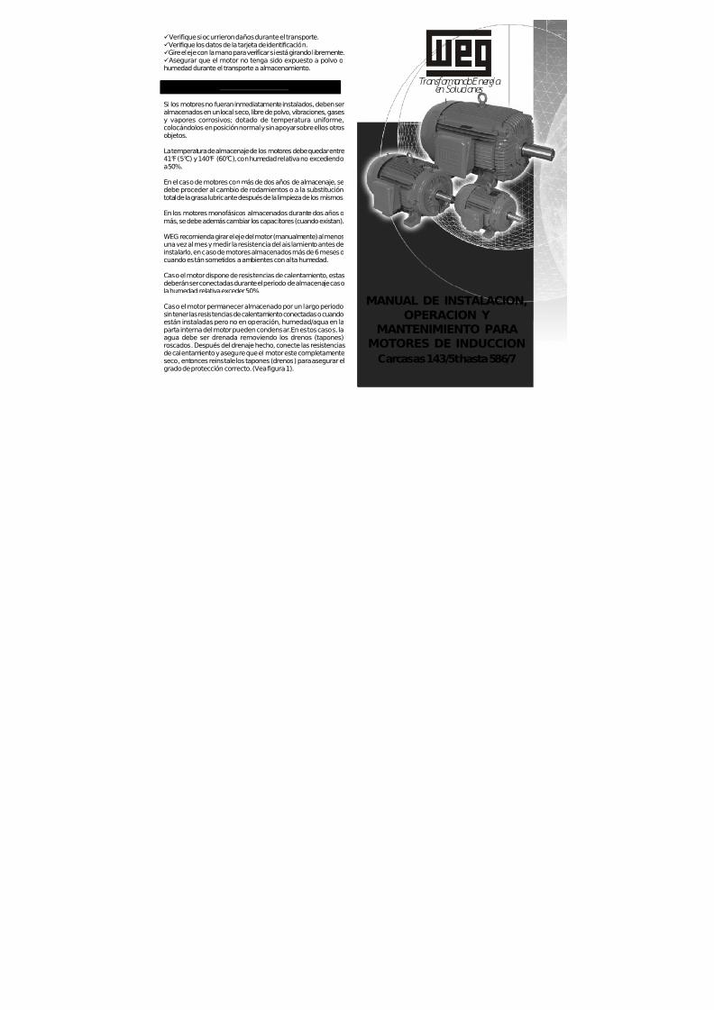
7/17/2019 R05323-P-001A-X009-0042.pdf
http://slidepdf.com/reader/full/r05323-p-001a-x009-0042pdf 332/463
MANUAL DE INSTALACION,OPERACION Y
MANTENIMIENTO PARA
MOTORES DE INDUCCIONCarcasas 143/5t hasta 586/7
ü Verifique si ocurrieron daños durante el transporte.ü Verifique los datos de la tarjeta de identificación.üGire el eje con la mano para verificar si está girando libremente.ü Asegurar que el motor no tenga sido expuesto a polvo ohumedad durante el transporte a almacenamiento.
3. ALMACENAMIENTO
Si los motores no fueran inmediatamente instalados, deben ser
almacenados en un local seco, libre de polvo, vibraciones, gasesy vapores corrosivos; dotado de temperatura uniforme,colocándolos en posición normal y sin apoyar sobre ellos otrosobjetos.
La temperatura de almacenaje de los motores debe quedar entre41°F (5°C) y 140°F (60°C), con humedad relativa no excediendoa 50%.
En el caso de motores con más de dos años de almacenaje, sedebe proceder al cambio de rodamientos o a la substitucióntotal de la grasa lubricante después de la limpieza de los mismos.
En los motores monofásicos almacenados durante dos años omás, se debe además cambiar los capacitores (cuando existan).
WEG recomienda girar el eje del motor (manualmente) al menosuna vez al mes y medir la resistencia del aislamiento antes deinstalarlo, en caso de motores almacenados más de 6 meses ocuando están sometidos a ambientes con alta humedad.
Caso el motor dispone de resistencias de calentamiento, estasdeberán ser conectadas durante el periodo de almacenaje casola humedad relativa exceder 50%.
Caso el motor permanecer almacenado por un largo periodosin tener las resistencias de calentamiento conectadas o cuandoestán instaladas pero no en operación, humedad/agua en laparta interna del motor pueden condensar. En estos casos, laagua debe ser drenada removiendo los drenos (tapones)roscados. Después del drenaje hecho, conecte las resistenciasde calentamiento y asegure que el motor este completamenteseco, entonces reinstale los tapones (drenos) para asegurar elgrado de protección correcto. (Vea figura 1).
Transformando Energía en Soluciones

7/17/2019 R05323-P-001A-X009-0042.pdf
http://slidepdf.com/reader/full/r05323-p-001a-x009-0042pdf 333/463
LA INTENCION DE ESTE MANUAL ES PROVEER INFORMACIONES IMPORTANTES QUE DEBEN SER SEGUIDAS DURANTE TRANSPORTE, INSTALACION ,OPERACION Y MANTENIMIENTO DE LOS MOTORES
WEG. ENTONCES, RECOMENDAMOS LEER ATENTAMENTE ESTE MANUAL ANTES DE LAINSTALACION Y OPERACION DEL MOTOR.
PARA ASEGURAR INTEGRIDAD FISICA DE LAOPERACION Y PROTECCION MATERIAL, TODA LA
INFORMACION INCLUIDA EN ESTE MANUAL DEBERA
SER EXTREMAMENTE SEGUIDA
I
INDICE
1. MANEJO Y TRANSPORTE 2. VERIFICACION EN LA RECEPCION 3. ALMACENAMIENTO 4. INSTALACION
4.1 - Se g ur id ad 4.2 - Co n d ic i o n es d e o p e r a c ió n 4.3 - Fu n da c io n es d e l mo t o r 4.4 - A gu je ro s d e D r e na je 4.5 - B ala nc eo 4.6 - Al in ea c ió n 4.7 - Ac o p lam ie nt os 4 .8 - Conex ión e léct r i ca 4 .9 - Métodos de a r ranque 4 .10 - D ispos it i vo de p ro tecc ión 4.11 - Puesta en Marcha
5. MANTENIMIENTO 5.1 - L ub ri ca c ión 5.1.1 - Mo tores sin grasera 5.1 .2 - Motores con grasera 5.1.3 - Compatib i l idad d e la grasa MOBIL Pol i rex EM
con o tros t ipos de grasa 5.2 - DESMONTAJE Y MONTAJE
6. PARTES Y PIEZAS - REPUESTOS 7. MOTORES PARA USO CON CONVERTIDOR DE FRECUENCIA
7.1 - Mo to re s S ta nd a rd 7 .2 - Mo t o re s I nv er te r Du ty 7 .3 - A is lam i en t o de r odam ien to s
8. INFORMACIONES ADICIONALES 8 .1 - Mo to res pa ra Áreas de Riesgo 8.1 .1 - Gen era l 8.1.2 - Instalac ión 8 .1 .3 - Chequeo y Man ten imien to 8.1.4 - Reparos en Moto res a Prueba de Explosión
9. TERMINOS DE GARANTIA
1 – MANEJO Y TRANSPORTE
LOS MOTORES NO DEBEN SER IZADOS POR ELEJE, UTILIZE LOS CANCAMOS DE SUSPENSION,
ESPECIFICOS PARA ESTE PROPOSITO
LOS MOTORES CON RODAMIENTOS DE RODILLOS O DE CONTACTO ANGULAR ESTAN PROTEGIDOS,
DURANTE EL TRANSPORTE, CONTRA DAÑOS POR MEDIO DE UN D ISPOSITIVO DE BLOQUEO DEL EJE
LOS DISPOSITIVOS DE BLOQUEO DEBEN SER UTILIZADOS SIEMPRE QUE SE TRANSPORTE
EL MOTOR, AUNQUE ESTO IMPLIQUE TENERLO QUE DESACOPLAR NUEVAMENTE
DE LA MAQUINA ACCIONADA
Equipamientos de alzamiento, cuando suministrados, sonproyectados solamente para la sustentación del motor.Si el motor por su diseño constructivo tiene dos cáncamos de
suspensión, use dispositivos que permitan el izamiento porambos elementos al mismo tiempo.El izamiento así como el descenso del motor deben ser realizadosen forma suave, sin golpes, caso contrario los rodamientospueden sufrir daños.
I
I
I
2. VERIFICACION EN LA RECEPCION
· En la recepción del motor, verifique si ocurrieron daños duranteel transporte.
En el caso de verificar cualquier daño, avisar inmediatamente latransportadora, la compañía aseguradora y WEG. No avisar latransportadora, la compañía aseguradora y WEG puede resultaen la pérdida de la garantía del producto.
No remueva la grasa de protección de la punta de eje, tampoco lostapones que cierran los agujeros de la caja de conexiones, casoexistir. Estos ítems de protección deben ser mantenidos hasta quela instalación completa sea concluida. Después de la remoción desu embalaje, una completa inspección visual debe ser hecha en

7/17/2019 R05323-P-001A-X009-0042.pdf
http://slidepdf.com/reader/full/r05323-p-001a-x009-0042pdf 334/463
SHIJIAZHUANG KINGDA PUMP INDUSTRY GROUP CO., LTD
TOROMOCHO PROJECT
HARD METAL SLURRY PUMP
LONG-TERM STORAGE INSTRUCTIONS
Hard Metal Slurry Pumps
R05323-P-001A
SHIJIAZHUANG KINGDA PUMP INDUSTRY GROUP Co., Ltd
1st September, 2010

7/17/2019 R05323-P-001A-X009-0042.pdf
http://slidepdf.com/reader/full/r05323-p-001a-x009-0042pdf 335/463
SHIJIAZHUANG KINGDA PUMP INDUSTRY GROUP CO., LTDLONG-TERM STORAGE INSTRUCTIONS
TOROMOCHO PROJECTR05323-P-001A, REV A
1
LONG-TERM STORAGE INSTRUCTIONS
The pumps are shipped fully protected for the commercial shipping and handling that is required for a
given order. Upon receipt, it is necessary that the customer, or an agent of the customer, conduct a
thorough inspection of all pumps and components for completeness of delivery and possible handling
damage. Some small spare parts may be packed separately, if you find damage or loss, please contact
with Kingda and Freight Company immediately.
Al l shortages should be immediately reported to Kingda.
Note: Any components damaged in shipment should be noted and a claim filed by the responsib le
shipping party with the freight company.
Kinda does not warrant any pump or pump components which become damage due to a failure
which adhere to the instructions listed below.

7/17/2019 R05323-P-001A-X009-0042.pdf
http://slidepdf.com/reader/full/r05323-p-001a-x009-0042pdf 336/463
SHIJIAZHUANG KINGDA PUMP INDUSTRY GROUP CO., LTDLONG-TERM STORAGE INSTRUCTIONS
TOROMOCHO PROJECTR05323-P-001A, REV A
2
Outdoor Storage
1. Site selection for outdoor storage of pump and pump components as following:
1.1: Level, well-drained, firm surface, clean, and dry location.
1.2: The environment for pump storage must be dry, dust-free, and well-ventilated. Avoid damage the
bearing because of vibration. The vibration of the storage place is less than 0.2mm/S.
1.3: Isolated or barricaded from possibility of physical damage from transport vehicles, earth working
equipment, and other site erected equipment.
1.4: The inlets and outlets of pumps should be plugged to prevent sundries entering pump cavity.
Accessible for periodic inspection and maintenance.
2. All the pump or pump baseplate should be supported under each corner of its base to allow it to
“breathe”. Supports (steel beams or wood timbers) of significant size and strength should be placed under
each corner. All components shipped in crates and pallets must be located and supported such that air can flow under
and around the shipping container.
3. Upon receipt of the Pump and pump components, an initial inspection must be made to ensure that all
protective coatings and/or devices have not been compromised during shipping and handling.
If discrepancies are found, corrective action must be taken to ensure adequate protection of the
equipment during storage.
Particular attention must be paid to:
(a) All bright steel surfaces, journal and machined; such as shafts, end flanges.
(b) All shaft sleeve and bearing surfaces.
(c) All the roller bearing.
(d) All machined surfaces protected with paint
4. It is recommended that all electric motors be stored indoors. The motors are to be stored and protected
in accordance with the requirements of the motor manufacture. Some motors may have low voltage
internal heaters that are to be energized during storage.
If indoor store is not possible, it is necessary that these pumps and components be covered by a tarp
which is loose enough to let the component breathe. In areas of high relative humidity, it may be
necessary to use a desiccant to keep it free of moisture.
Note: WEG will provide the Motor Storage Instructions on all motors supplied by us.
Some motors may have low voltage internal heaters that are to be energized during storage.
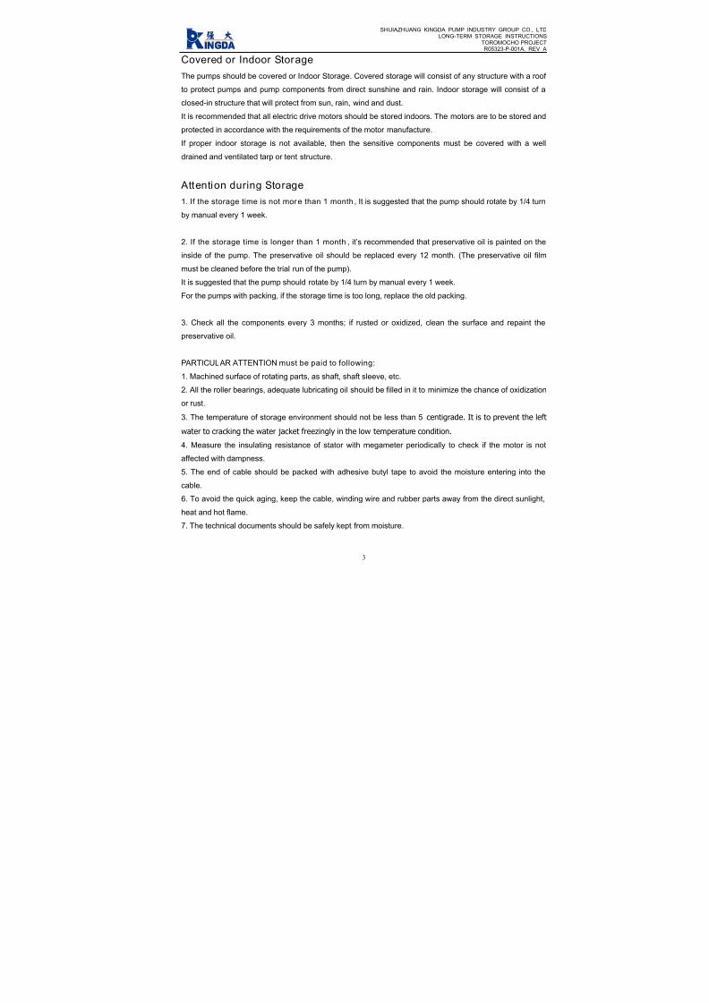
7/17/2019 R05323-P-001A-X009-0042.pdf
http://slidepdf.com/reader/full/r05323-p-001a-x009-0042pdf 337/463
SHIJIAZHUANG KINGDA PUMP INDUSTRY GROUP CO., LTDLONG-TERM STORAGE INSTRUCTIONS
TOROMOCHO PROJECTR05323-P-001A, REV A
3
Covered or Indoor Storage
The pumps should be covered or Indoor Storage. Covered storage will consist of any structure with a roof
to protect pumps and pump components from direct sunshine and rain. Indoor storage will consist of a
closed-in structure that will protect from sun, rain, wind and dust.
It is recommended that all electric drive motors should be stored indoors. The motors are to be stored and
protected in accordance with the requirements of the motor manufacture.
If proper indoor storage is not available, then the sensitive components must be covered with a well
drained and ventilated tarp or tent structure.
Attention during Storage
1. If the storage time is not more than 1 month, It is suggested that the pump should rotate by 1/4 turn
by manual every 1 week.
2. If the storage time is longer than 1 month , it’s recommended that preservative oil is painted on the
inside of the pump. The preservative oil should be replaced every 12 month. (The preservative oil film
must be cleaned before the trial run of the pump).
It is suggested that the pump should rotate by 1/4 turn by manual every 1 week.
For the pumps with packing, if the storage time is too long, replace the old packing.
3. Check all the components every 3 months; if rusted or oxidized, clean the surface and repaint the
preservative oil.
PARTICULAR ATTENTION must be paid to following:
1. Machined surface of rotating parts, as shaft, shaft sleeve, etc.
2. All the roller bearings, adequate lubricating oil should be filled in it to minimize the chance of oxidization
or rust.
3. The temperature of storage environment should not be less than 5 centigrade. It is to prevent the left
water to cracking the water jacket freezingly in the low temperature condition.
4. Measure the insulating resistance of stator with megameter periodically to check if the motor is not
affected with dampness.
5. The end of cable should be packed with adhesive butyl tape to avoid the moisture entering into the
cable.
6. To avoid the quick aging, keep the cable, winding wire and rubber parts away from the direct sunlight,
heat and hot flame.
7. The technical documents should be safely kept from moisture.

7/17/2019 R05323-P-001A-X009-0042.pdf
http://slidepdf.com/reader/full/r05323-p-001a-x009-0042pdf 338/463
SHIJIAZHUANG KINGDA PUMP INDUSTRY GROUP CO., LTDLONG-TERM STORAGE INSTRUCTIONS
TOROMOCHO PROJECTR05323-P-001A, REV A
4
Storage/Maintenance
Period Task Action
Initial receipt of pumps
and pump components
Inventory and
Inspection
Re-establish the integrity of all protective coatings and covering devices. Check
for damage to the surface finish (paint) that may allow rust or corrosion and
repaint as necessary.
-Report any shipping damages to the freight company.
-Report any shortages to Kingda.
After three (3) Months
of StorageInspection
Re-inspect all pump components, making sure no rust or oxidation is starting to
form on machined surfaces. If rust or oxidation is found, the surface(s) must be
cleaned and a protective coating applied.
After six (6) Months ofStorage
Inspection
Re-inspect all pump components, making sure no rust or oxidation is starting to
form on machined surfaces. If rust or oxidation is found, the surface(s) must be
cleaned and a protective coating applied.
The customer shall maintain a Periodic Inspection and Maintenance Log documenting condition and
efforts to maintain the protection of the Pump and components.

7/17/2019 R05323-P-001A-X009-0042.pdf
http://slidepdf.com/reader/full/r05323-p-001a-x009-0042pdf 339/463

7/17/2019 R05323-P-001A-X009-0042.pdf
http://slidepdf.com/reader/full/r05323-p-001a-x009-0042pdf 340/463
Toromocho Project
Lubrication Schedule
Vendor: Shijiazhuang Kingda Pump Industry Group Co., Ltd Date: 28th October, 2010
Equipment Name: Hard Metal Slurry Pumps PO No.: R05323-P-001A
Equipment No. Pump ModelPump Speed
(RPM)Lubricant Type
Lubricant
Manufacturer
Lubrica
Positio
245-PP-004/005/006/106 M150KSH-EB/T 810~1050
lithium grease #2 or #3 —— pump e
lithium grease #2 or #3 —— motor e
245-PP-008/108 M50KSG-DB/T 1350
lithium grease #2 or #3 —— pump e
lithium grease #2 or #3 —— motor e
260-PP-065/165 M75KSG-EB/T 1200~1280
lithium grease #2 or #3 —— pump e
lithium grease #2 or #3 —— motor e

7/17/2019 R05323-P-001A-X009-0042.pdf
http://slidepdf.com/reader/full/r05323-p-001a-x009-0042pdf 341/463
Tormocho Project
LUBRICATION SCHEDULE
PO Number: R05323-P-001 Equipment: Standard End Suction Pumps
Vendor :SHIJIAZHUANG KINGDA PUMP Vendor contact Name : Wang zhao(Wendy)
page 1 of 1 E-mail :[email protected]
EQUIP NO. DESCRIPTION, WHERE USED LUBRICANT TYPE QUANTITY MANUFACTURERF
R
245-PP-004
245-PP-005
245-PP-006
245-PP-106
Front bearing NU322-C3POLYREX EM
(polyurea grease
60g
MOBIL
Rear bearing 6319-C3 45g
245-PP-008/108Front bearing NU319-C3 POLYREX EM
(polyurea grease
45gMOBIL
Rear bearing 6316-C3 34g
260-PP-065/165Front bearing NU319-C3 POLYREX EM
(polyurea grease
45gMOBIL
Rear bearing 6316-C3 34g

7/17/2019 R05323-P-001A-X009-0042.pdf
http://slidepdf.com/reader/full/r05323-p-001a-x009-0042pdf 342/463
7/17/2019 R05323-P-001A-X009-0042.pdf
http://slidepdf.com/reader/full/r05323-p-001a-x009-0042pdf 343/463

7/17/2019 R05323-P-001A-X009-0042.pdf
http://slidepdf.com/reader/full/r05323-p-001a-x009-0042pdf 344/463
WEG INDÚSTRIAS S/A
ELECTRIC MOTOR WIRING DIAGRAM
• SINGLE SPEED 380V 60HZ MOTOR:

7/17/2019 R05323-P-001A-X009-0042.pdf
http://slidepdf.com/reader/full/r05323-p-001a-x009-0042pdf 345/463

7/17/2019 R05323-P-001A-X009-0042.pdf
http://slidepdf.com/reader/full/r05323-p-001a-x009-0042pdf 346/463
INDEX
Item No. Description
1 Datasheets (Pump & Motor), Performance Curve
2 Installation Drawing
3 Assembly Drawing
4 Lifting Diagram
5 ITP
6 Ultrasonic Flaw Detection Specification For Shaft Parts
7 Welding Process Specification
8 Material Report For Main Parts
9 Ultrasonic Flaw Detection Report
10 Inspection Report For Parts
11 Inspection Record For Assembly
12 Inspection Record For Painting
13 Inspection Record For Packing
14 Hydraulic Pressure Test Report
15 Performance Test Procedure
16 Performance Test Details Sheet
17 Performance Test Report
18 Vibration Report
19 Noise Report
20 Pump IOM
21 Motor IOM
22 Long Term Storage Instructions
23 Spare Parts List for Operation and 1 Year (Un-priced)
24 Pump Lubrication Schedule
25 Motor Lubrication Schedule
26 Packing List
27 Certification of Conformance
28 Motor Wiring Diagram

7/17/2019 R05323-P-001A-X009-0042.pdf
http://slidepdf.com/reader/full/r05323-p-001a-x009-0042pdf 347/463

7/17/2019 R05323-P-001A-X009-0042.pdf
http://slidepdf.com/reader/full/r05323-p-001a-x009-0042pdf 348/463

7/17/2019 R05323-P-001A-X009-0042.pdf
http://slidepdf.com/reader/full/r05323-p-001a-x009-0042pdf 349/463

7/17/2019 R05323-P-001A-X009-0042.pdf
http://slidepdf.com/reader/full/r05323-p-001a-x009-0042pdf 350/463

7/17/2019 R05323-P-001A-X009-0042.pdf
http://slidepdf.com/reader/full/r05323-p-001a-x009-0042pdf 351/463

7/17/2019 R05323-P-001A-X009-0042.pdf
http://slidepdf.com/reader/full/r05323-p-001a-x009-0042pdf 352/463

7/17/2019 R05323-P-001A-X009-0042.pdf
http://slidepdf.com/reader/full/r05323-p-001a-x009-0042pdf 353/463

7/17/2019 R05323-P-001A-X009-0042.pdf
http://slidepdf.com/reader/full/r05323-p-001a-x009-0042pdf 354/463
C E RT I F I E DF OR
C ON S T R U C T I ON
B y : W an gZ h a o ( W en d y )
D a t e: 2 5 O c t o b er 2 0 1 0
Mf r :
S HI J I A Z H UA N GK I N GDA
P UMP

7/17/2019 R05323-P-001A-X009-0042.pdf
http://slidepdf.com/reader/full/r05323-p-001a-x009-0042pdf 355/463

7/17/2019 R05323-P-001A-X009-0042.pdf
http://slidepdf.com/reader/full/r05323-p-001a-x009-0042pdf 356/463

7/17/2019 R05323-P-001A-X009-0042.pdf
http://slidepdf.com/reader/full/r05323-p-001a-x009-0042pdf 357/463
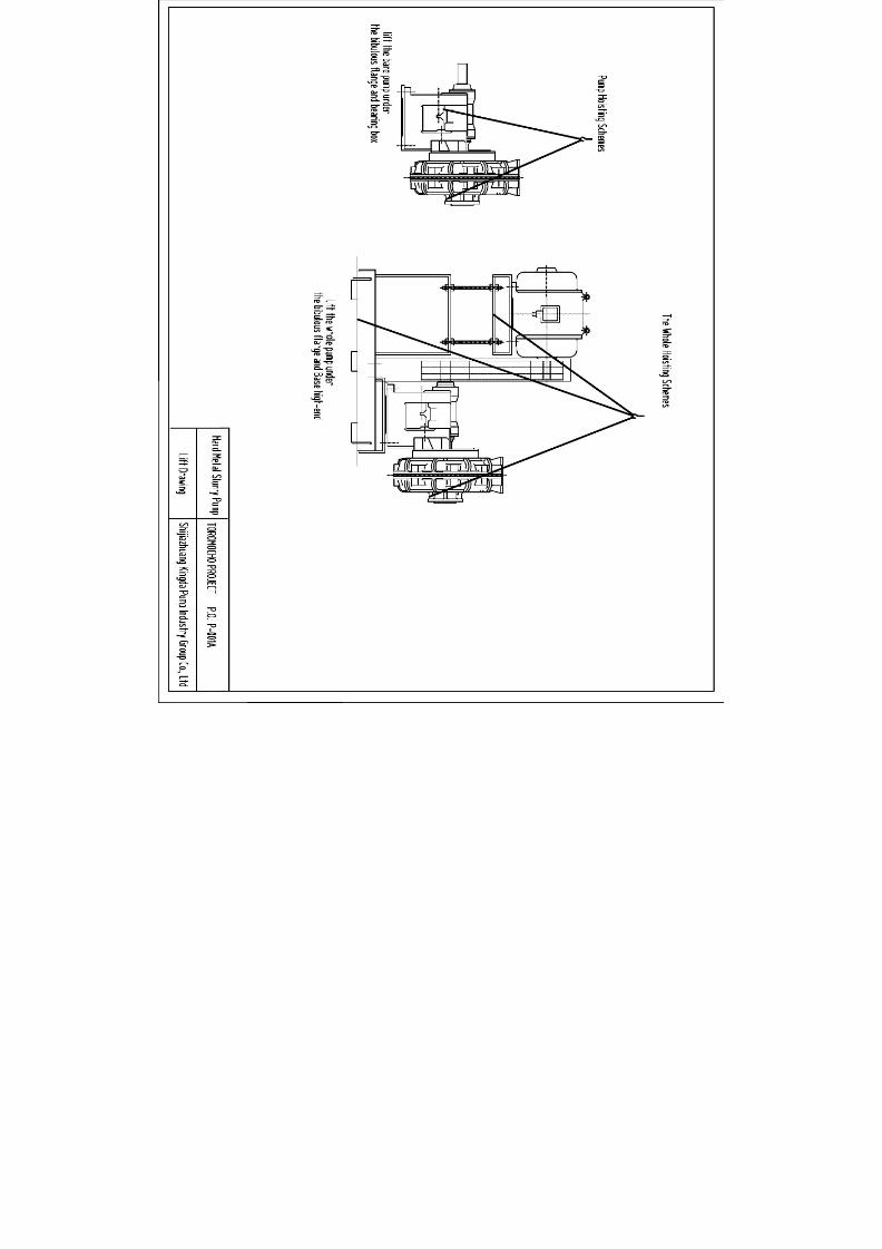
7/17/2019 R05323-P-001A-X009-0042.pdf
http://slidepdf.com/reader/full/r05323-p-001a-x009-0042pdf 358/463

7/17/2019 R05323-P-001A-X009-0042.pdf
http://slidepdf.com/reader/full/r05323-p-001a-x009-0042pdf 359/463

7/17/2019 R05323-P-001A-X009-0042.pdf
http://slidepdf.com/reader/full/r05323-p-001a-x009-0042pdf 360/463
No. 239, Tianshan Street, Shijiazhuang City, Hebei Province, ChinaTel: +86 311 80908109 Fax: +86 311 80908116 Email: [email protected]
Inspection and Test Plan
PO No.: R05323-P-001A, Equipment Name: Hard Metal Slurry Pumps
Item
No.
Inspection &
Test Item
Acc eptance
Criteria
Inspection
Methods
Acceptance
Doc.
Review
Doc.
Executive
Time Ma
1 Acceptance of Contract Documents
1.1 Contract Inspection
Signed Contract and
Requirements
Check the Contract and
Requirements
Requirements
by the Contract
Vendor
Departm
1.2
Dimensional
Drawings
Certified Drawings and
Documents
Drawings and Document
Inspection
Drawings submitted
by Vendor
Vendor
Departm
2 Inspectio n on Raw Materials and Purchased Parts
2.1
Inspection of raw
materials
JB/T8096-1998
GB9439-1998
(ASTM A48-2003)
GB1348-1998
(ASTM A536-2003)
GB2100-2002
(ASTM A743/743a-1993a)
GB/T8263-1999
(ASTM A532M-99)
GB699-1988
(ASTM A36/A36M-2005)
SBB121.1-29-1997
SBB125.1-28-1997
SBB302.1-12-2008
SBB0158-2003
Visual inspection, Chemical test,
Spectrometer, General gauge
Comply with the
Standards
Material Composition
Analysis and Mechanical
Prosperities Report,
Product Compliance
Certificate
After arrival at
Factory
Quality
Dept.
2.2 Bearings
Contract Technical
Requirements
Visual inspection, check Product
Compliance Certificate
Comply with
Contract technical
Product Compliance
After arrival at
Factory
Quality
Manage

7/17/2019 R05323-P-001A-X009-0042.pdf
http://slidepdf.com/reader/full/r05323-p-001a-x009-0042pdf 361/463
No. 239, Tianshan Street, Shijiazhuang City, Hebei Province, ChinaTel: +86 311 80908109 Fax: +86 311 80908116 Email: [email protected]
requirement Dept.
2.3 WEG Motors
Contract Technical
Requirements
Visual inspection, check Product
Compliance Certificate
Comply with
Contract technical
requirement
Product Compliance
After arrival at
Factory
Quality
Manage
Dept.
3 Inspectio n and Test in Pump Product ion Process
3.1
Inspection Before
Casting
SBB139-2001
SBB131-1998
SBB122-2000
Spectrometer
Comply with the
Standards
Material Composition
Analysis and Mechanical
Prosperities Report
Before Pouring
Quality
Manage
Dept.
3.2 Castings
SBB139-2001
SBB122-2000
SBB131-1998
GB1348-1988
(ASTM A536-2003)
Spectrometer,
Carbon-Sulfur Analyzer,
Chemical Test, General Gauge
Comply with the
Standards
Material Composition
Analysis and Mechanical
Prosperities Report
After
heat treatment
Quality
Dept.
3.3 Heat TreatmentSBB131-1998
SBB165-2009
Hardness Tester,
Universal Tester
Comply with the
Standards
Heat Treatment
Report
After
heat treatment
Quality
Manage
Dept.
3.4
Inspection in
Machining Process
SBB2105-87
SBB061-2003
Drawing Requirements
General Tools,
Special Tools
Comply with the
Standards and
Drawing
Requirements
Machining Dimension
Inspection Record
During
Machining
Process
Quality
Manage
Dept.
3.5
Impeller Static
Balancing,
SBB061-2003 Balancing Test Frame
Comply with the
Standard
Impeller Static Blancing
Report
Static Balance
Test
Quality
Manage
Dept.
3.6 Shafft Inspection YB-T036.T-92 Ultrasonic Detection
Comply with the
Standard
Shaft Ultrasonics
Detection Report
Shaft Inspection
Test
Quality
Manage
Dept.
4 Assembl y, Test, Painting and Packing
4.1 Assembly SBB2103-2000 General Gauge
Comply with the
Standards and
Clearance Inspection
Record in Assembly
After Assembly
Quality
Dept.

7/17/2019 R05323-P-001A-X009-0042.pdf
http://slidepdf.com/reader/full/r05323-p-001a-x009-0042pdf 362/463
No. 239, Tianshan Street, Shijiazhuang City, Hebei Province, ChinaTel: +86 311 80908109 Fax: +86 311 80908116 Email: [email protected]
SBB064-2004
Drawing Requirements
Drawing
Requirements
4.2
Hydraulic
Pressure Test
GB/T5656-94,
SBB064-1998,
(HI 1.6-2000/API610)
Visual Inspection,
Pressure gauge
Comply with the
standards
Hydraulic Pressure Test
Report
After Assembly,
Witness Point
Quality
Dept.
4.3
Performance
Noise
Vibration
Contract Technical
Requirements
GB3216-2005
(HI 1.6-2000/
ASME B73.1M/B73.2M)
JB/T8097-1999
GB3214-91,
GB10890,
GB10889
SBB064-2004
Pump Test Station
Comply with the
Standards and
Contract Technical
Requirements
Pump Performance
Running Test Report
After Assembly,
Witness Point
Quality
Dept.
4.4 Painting
Contract Technical
Requirements SBB097-2008
SBB0159-1998
JB/T4297-1992
Visual Inspection,
Coating Thickness Meter
Comply with the
Standards and
Contract Technical
Requirements
Assembly Inspection
Record
After Painting
Quality
Dept.
4.5 Packing
Contract Technical
Requirements
SBB0157-1997
SBB0167-2009
GB/T13384-1992
Visual Inspection
Comply with the
Standards and
Contract Technical
Requirements
Assembly Inspection
Record
After Packing
Quality
Dept.
5 Relese for Shippment
5.1
Release for
shipment
Contract requirements As per Contract Requirements
Release for
shipment from
Owner
Hold Point
7/17/2019 R05323-P-001A-X009-0042.pdf
http://slidepdf.com/reader/full/r05323-p-001a-x009-0042pdf 363/463
ULTRASONIC FLAW DETECTION
SPECIFICATION
FOR
SHAFT PARTS
TOROMOCHO PROJECT
Supplier: SHIJIAZHUANG KINGDA PUMP INDUSTRY GROUP CO., LTD
Reviewed And Approved:
Date: November, 2011

7/17/2019 R05323-P-001A-X009-0042.pdf
http://slidepdf.com/reader/full/r05323-p-001a-x009-0042pdf 364/463
SHIJIAZHUANG KINGDA PUMP INDUSTRY GROUP CO., LTDULTRASONIC FLAW DETECTION SPECIFICATIONDoc No.: WPS-UD-2011, Date: Nov, 2011, Rev 00
NO. 239, TIANSHAN STREET, SHIJIAZHUANG CITY, HEBEI PROVINCE, CHINA
GENERAL TECHNICAL SPECIFICATION
FOR ULTRASONIC FLAW DETECTIOIN FOR SHAFT PARTS
1. General Provision
1.1 Application Scope
This Specification applies for the testing of internal incontinuity of forgings sourced by Kingda by using A
Type Pulse Reflection Ultrasonic Detection method.
This Specification is not applied to work piece of austenite coarse grained.
1.2 Acceptance Standard
GB/T 4162 Forged And Rolled Steel Bars - Method For Ultrasonic Testing
GB/T 7736 Ultrasonic Inspecting Method For Macro-Structure And Imperfection Of Steel
1.3 If special requirements, inspection and acceptance will be carried as per Standards in relative
agreements, drawing and process.
1.4 Requirements for Inspectors
The inspectors should have Ultrasonic Flaw Detection Technology Certification, and the Inspector who will
sign the Report must be qualified for II Grade or Above Certification.
2. Detection Equipment And Instruments
2.1 Ultrasonic Flaw Detector
The ultrasonic flaw detector should be tested for its fuction as per the methods specified in JB/T
10061-1999, and its quota should be meet following:
a). Surplus Sensitivity: N≥36dB
b). Vertical Linearity Tolerance: D≤6%
c). Horizontal Linearity Tolerance: δ≤1%
d). Dynamic Range: ≥30dB.
2.2 Probe
Usually straight beam probe is selected for detection; angle beam probe is selected for assistant detection.
The operation frequency of probe must meet the requirements to penetrate and explore the work piece,
nominal frequency of 2-5MHz is used, and probe crystal diameter or side length is 10-25mm.
2.3 Coupling Medium
Coupling medium whichever can give good coupling effect and is not harmful to body and work piece
should be selected.
The same coupling medium must be used for adjustment, calibration and inspection of equipments.

7/17/2019 R05323-P-001A-X009-0042.pdf
http://slidepdf.com/reader/full/r05323-p-001a-x009-0042pdf 365/463
SHIJIAZHUANG KINGDA PUMP INDUSTRY GROUP CO., LTDULTRASONIC FLAW DETECTION SPECIFICATIONDoc No.: WPS-UD-2011, Date: Nov, 2011, Rev 00
NO. 239, TIANSHAN STREET, SHIJIAZHUANG CITY, HEBEI PROVINCE, CHINA
2.4 Test Block
When test forged parts, the test block should be selected according to probe and condition of surface to be
detected, for example, CSI standard test block.
Equipment can also be adjusted according to test block as per GB/T 4162 or GB/T 7736.
3. Detection
3.1 Detection Method
Detection method is generally P-wave reflection, SH-wave reflection can be added if necessary.
A: Necessary detecting direction
B: Detecting direction which needs to be negotiated
Detection At Axial And Circumferential Direction For Shaft Parts
3.2 Detection Time
Usually the detection should be carried after entry of source parts into plant or after heat treatment.
If there any special requirements, the detection should be carried as per special time.
3.3 Detection Procedure
3.3.1 Treatment on Surface of Work Piece
Usually the roughness of surface of work piece should be R0≤6.3μm; Roughness may be enlarged for
coarse surface, but not more than 12.5μm.
The flaws as mill scale, dirties, paint and pit which can influence the acoustic coupling must be removed or
machined.
3.3.2 Adjustment of Instrument
3.3.2.1 Adjustment of Scan Speed
Generally it is required that forward base of first bottom wave should be not more than 80% of width of
oscilloscope screen in order to observe the situation of other signals after first bottom wave.
3.3.2.2 Adjustment of Sustained Sensitivity
For the work piece with thickness of position tested ≥3N, bottom wave adjustment method can be used;
For the work piece with thickness of position tested <3N or the surface is very rough, test pad adjustment

7/17/2019 R05323-P-001A-X009-0042.pdf
http://slidepdf.com/reader/full/r05323-p-001a-x009-0042pdf 366/463
SHIJIAZHUANG KINGDA PUMP INDUSTRY GROUP CO., LTDULTRASONIC FLAW DETECTION SPECIFICATIONDoc No.: WPS-UD-2011, Date: Nov, 2011, Rev 00
NO. 239, TIANSHAN STREET, SHIJIAZHUANG CITY, HEBEI PROVINCE, CHINA
method can be used.
When the surface shape and roughness of test pad is different from the work piece, coupling compensation
and attenuation compensation methods can be used.
3.3.2.3 Adjustment of Scan Sensitivity
6dB should be amplified based on the inspection sensitivity in order to easily find the defects, but estimation
on the defects should be based on the inspection sensitivity level.
3.4 Inspection Frequency
3.4.1 If no special requirement, the sample test should be made as per SBB302.1-2008.
3.4.2 If any special requirements, the test should be made as per requirements.
3.4.3 For the tested work piece, whole detecting should be made.
3.5 Scan Detection
3.5.1 Scan Type
Usually whole scan should be used.
3.5.2 Scan Speed
In order to ensure the defects can be clearly found, the scan speed should not more than 150mm/s.
3.5.3 Scan Distance
It is required that 15% overlapping should be done between two scans.
3.6 Calibration of Instruments
After detection, the instrument should be calibrated for sensitivity; if the sensitivity can not meet the
requirements, calibration should be done.
4. Estimation of Defects
Usually defects will be estimated according to the reflection and bottom reflection results, including defect
position and size, if necessary, the nature of defects can be estimated.
4.1 Estimation of Defect Position
To determine the surface position of defect according to the probe work position;
To determine he depth of defects according to that tested in oscilloscope screen.
4.2 Estimation of Defect Size
4.2.1 For flat defect of small wafer size, equivalent size of defect should be estimated according to the echo
margin shown in oscilloscope screen.
4.2.2 For flat defect of large wafer size, the length and area of defect should be estimated by 6dB or half
wave height method.

7/17/2019 R05323-P-001A-X009-0042.pdf
http://slidepdf.com/reader/full/r05323-p-001a-x009-0042pdf 367/463
SHIJIAZHUANG KINGDA PUMP INDUSTRY GROUP CO., LTDULTRASONIC FLAW DETECTION SPECIFICATIONDoc No.: WPS-UD-2011, Date: Nov, 2011, Rev 00
NO. 239, TIANSHAN STREET, SHIJIAZHUANG CITY, HEBEI PROVINCE, CHINA
4.2.3 For the defect of volume type, circumferential direction detection method can be used.
5. Quality Estimation
Estimation should be made as per GB/T 4162 and GB/T 7736; if any, special requirements can be followed.
After the detection, if disputes, it can be confirmed by low-power etch test.
6. Inspection Record And Report
6.1 Inspection report include: specification, grade, heat number, standard, quality grade and quantity,
issued by who and date, etc.
6.2 Inspection record should include position of defect, size of equivalent, distance and length of defects,
and drop of bottom wave, etc.

7/17/2019 R05323-P-001A-X009-0042.pdf
http://slidepdf.com/reader/full/r05323-p-001a-x009-0042pdf 368/463

7/17/2019 R05323-P-001A-X009-0042.pdf
http://slidepdf.com/reader/full/r05323-p-001a-x009-0042pdf 369/463
SHIJIAZHUANG KINGDA PUMP INDUSTRY GROUP CO., LTD
WELDING PROCESS SPECIFICATION FOR REPAIR OF CASTINGS
Doc No.: WPS-KD-2011, Date: Oct, 2011, Rev 00
NO. 239, TIANSHAN STREET, SHIJIAZHUANG CITY, HEBEI PROVINCE, CHINA
Process Specification of Welding
1. Preparation Before Welding
1.1 Operator must be very well acquainted with the drawings, process specification and relative
documents.
1.2 Operator must carefully check the material grades and dimensions of parts and casting
which are going to be welded.
1.3 Calibers and scales must be marked with inspection certificate. The tools and auxiliary
devices must be reliable.
1.4 The welding machine must be in good condition, grounding and good in insulation.
1.5 Select welding materials as per specification.
1.6 Welding rods must be complete dry, if the rods are wet, make dry treatment as following
table:
Dry Methods for Welding Rod
Type of Rod Dry Temperature () Dry Time (hour)
acid-type 70~150 1~1.5
alkaline-type 250~350 1~2
Note: usually, the acid rod may not be dried before using, the alkaline rod (including S.S. rod) must be dried
treatment before using.
2. Welding
2.1 Clear water, oil stain, rust and burrs within 20mm to 30mm at two sides of weld seam and
bevel before welding.
2.2 For the parts to be beveled, the shape and dimension of bevel should conform to GB985-88
Standard.
2.3 Select welding rod as following Specification Table:
Selection of Welding Rod
Thickness of Welding Part (mm) Diameter of Rod (mm)
≤4
4~12
>12
≤3.2
3.2~4.0
≥4.0
2.4 Welding Current Selection of Common Welding Rod as following:
Reference Current (A)

7/17/2019 R05323-P-001A-X009-0042.pdf
http://slidepdf.com/reader/full/r05323-p-001a-x009-0042pdf 370/463
SHIJIAZHUANG KINGDA PUMP INDUSTRY GROUP CO., LTD
WELDING PROCESS SPECIFICATION FOR REPAIR OF CASTINGS
Do .: WPS-KD-2011, Date: Oct, 2011, Rev 00
NO. 239, TIANSHAN STREET, SHIJIAZHUANG CITY, HEBEI PROVINCE, CHINA
c No
Rod Dia.
(mm)
Welding Grade
2.5 3.2 4.0 5.0
E4303 70~90 90~130 160~220 220~270
E4303 70~90 90~130 160~190 180~230
Note: upper limit for thick plate; the current of horizontal welding is about 10% less than downward welding.
2.5 General Principle for Welding Procedure
2.5.1 It must not produce rigid constraint force against the others of welding seam at the
beginning welding.
2.5.2 One end of each seam should be kept shrink freely at welding.
2.5.3 If the seam length is ≤1000mm for manual arc welding, generally continuous straight
welding method is used; back-step welding or section back-step welding may be used when
length is ≥1000mm.
2.6 Generating the arc: it is forbidden to generate the arc on the machined surface and locating
surface; the arc should be generated on the run-on plate and then transit to workpiece.
2.7 Arc Manipulation
2.7.1 Screw type is suitable for the first layer with any welding position and thin plate welding.
2.7.2 Wave type is suitable for the surface welding of downward welding, horizontal welding,
and overhead welding.
2.7.3 “8” shape type is suitable for downward and surface welding.
2.7.4 Zigzag type is suitable for horizontal welding.
2.8 Welding: before welding, the current should be regulated on the test plate till the current is
suitable.
2.8.1 Downward welding: the welding seam is at on horizontal level. arc manipulation should be
steady and fully fill the arc crater.
2.8.2 Vertical welding: the welding seam is vertical to the level ground. When vertical welding,
short arc small current should be used, don’t swing the rod bigly.
2.8.3 Overhead welding and horizontal welding: welding seam is horizontal or overhead
position. Shortest arc and smallest current should be kept to ensure fused drop transmitted to
metal.
2.9 Correction and Cleaning of Weldment

7/17/2019 R05323-P-001A-X009-0042.pdf
http://slidepdf.com/reader/full/r05323-p-001a-x009-0042pdf 371/463
SHIJIAZHUANG KINGDA PUMP INDUSTRY GROUP CO., LTD
WELDING PROCESS SPECIFICATION FOR REPAIR OF CASTINGS
Doc No.: WPS-KD-2011, Date: Oct, 2011, Rev 00
NO. 239, TIANSHAN STREET, SHIJIAZHUANG CITY, HEBEI PROVINCE, CHINA
2.9.1 Make the correction on the deforms produced in welding with flame correction or
mechanical correction.
2.9.2 Clean spatters, slags and flashes after welding.
2.9.3 The key parts and rigid parts should be distressing tempering treatment after welding.
3. Quality Requirements
3.1 Inspect the weldments for surface appearance and quality as per drawing and specification.
3.2 Welding seam should conform to Welding Seam Quality Standard.
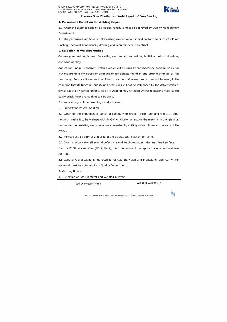
7/17/2019 R05323-P-001A-X009-0042.pdf
http://slidepdf.com/reader/full/r05323-p-001a-x009-0042pdf 372/463
SHIJIAZHUANG KINGDA PUMP INDUSTRY GROUP CO., LTD
WELDING PROCESS SPECIFICATION FOR REPAIR OF CASTINGS
Doc No.: WPS-KD-2011, Date: Oct, 2011, Rev 00
NO. 239, TIANSHAN STREET, SHIJIAZHUANG CITY, HEBEI PROVINCE, CHINA
Process Specification for Weld Repair of Iron Casting
1. Permission Condition for Welding Repair
1.1 When the castings need to be welded repair, it must be approved by Quality Management
Department.
1.2 The permissive condition for the casting welded repair should conform to SBB122 <Pump
Casting Technical Conditions>, drawing and requirements in Contract.
2. Selection of Welding Method
Generally arc welding is used for casting weld repair, arc welding is divided into cold welding
and heat welding.
Application Range: Generally, welding repair will be used at non-machined position which has
low requirement for stress or strength or for defects found in and after machining or fine
machining. Because the correction of heat treatment after weld repair can not be used, in the
condition that its function (quality and precision) will not be influenced by the deformation or
stress caused by partial heating, cold arc welding may be used; when the heating material will
easily crack, heat arc welding can be used.
For iron casting, cold arc welding usually is used.
3. Preparation before Welding
3.1 Clean up the impurities at defect of casting with shovel, chisel, grinding wheel or other
methods, make it to be V shape with 60-80° or X bevel to expose the metal, sharp angle must
be rounded. All existing web cracks were arrested by drilling 4-8mm holes at the ends of the
cracks.
3.2 Remove the oil dirty at and around the defects with solution or flame.
3.3 Brush muddy water all around defect to avoid weld drop attach the machined surface.
3.4 Use Z308 pure nickel rod (Ф3.2, Ф4.2), this rod is required to be kept for 1 hour at temperature of
80-120.
3.5 Generally, preheating is not required for cold arc welding; if preheating required, written
approval must be obtained from Quality Department.
4. Welding Repair
4.1 Selection of Rod Diameter and Welding Current
Rod Diameter (mm) Welding Current (A)

7/17/2019 R05323-P-001A-X009-0042.pdf
http://slidepdf.com/reader/full/r05323-p-001a-x009-0042pdf 373/463
SHIJIAZHUANG KINGDA PUMP INDUSTRY GROUP CO., LTD
WELDING PROCESS SPECIFICATION FOR REPAIR OF CASTINGS
Doc No.: WPS-KD-2011, Date: Oct, 2011, Rev 00
NO. 239, TIANSHAN STREET, SHIJIAZHUANG CITY, HEBEI PROVINCE, CHINA
Ф3.2 70-100
Ф4.2 100-140
4.2 The seams should be successively welded layer by layer. Welding length of single layer is
10-15mm, beat the welding seam with 0.5-1.0 kg hammer to make the seam to be spot shape;
after the temperature of welded position is cooled down to 100, then proceed to welding.
When the welding repair is multi-layer, repeat the operation as single layer welding.
5. Cleaning After Welding
Trim the welding seam on the machined and nonmachined surface with grinding wheel, and
clear the weld drop on the casting and machined surface.
6. Inspection After Welding
6.1 For the requirements of relieving of stress, make inspection after the heat treatment.
6.2 Inspect the grinded effect of welded position to check if it can meet the requirements for
welding repair.
6.3 If the welding position is on non machined surface, check if the welded position is as smooth
as casting itself.
6.4 If the welding position is on the machined surface, check if the welded junction can meet
the requirements of machining.
6.5 Besides required NDT, usually visual inspection is just needed to conform if the weld repairs
meet the quality requirements, defects are left after welding.
6.6 For the casting sustaining the liquid pressure or air pressure, the air tight hydrostatic test
or gas inspection.

7/17/2019 R05323-P-001A-X009-0042.pdf
http://slidepdf.com/reader/full/r05323-p-001a-x009-0042pdf 374/463

7/17/2019 R05323-P-001A-X009-0042.pdf
http://slidepdf.com/reader/full/r05323-p-001a-x009-0042pdf 375/463

7/17/2019 R05323-P-001A-X009-0042.pdf
http://slidepdf.com/reader/full/r05323-p-001a-x009-0042pdf 376/463

7/17/2019 R05323-P-001A-X009-0042.pdf
http://slidepdf.com/reader/full/r05323-p-001a-x009-0042pdf 377/463
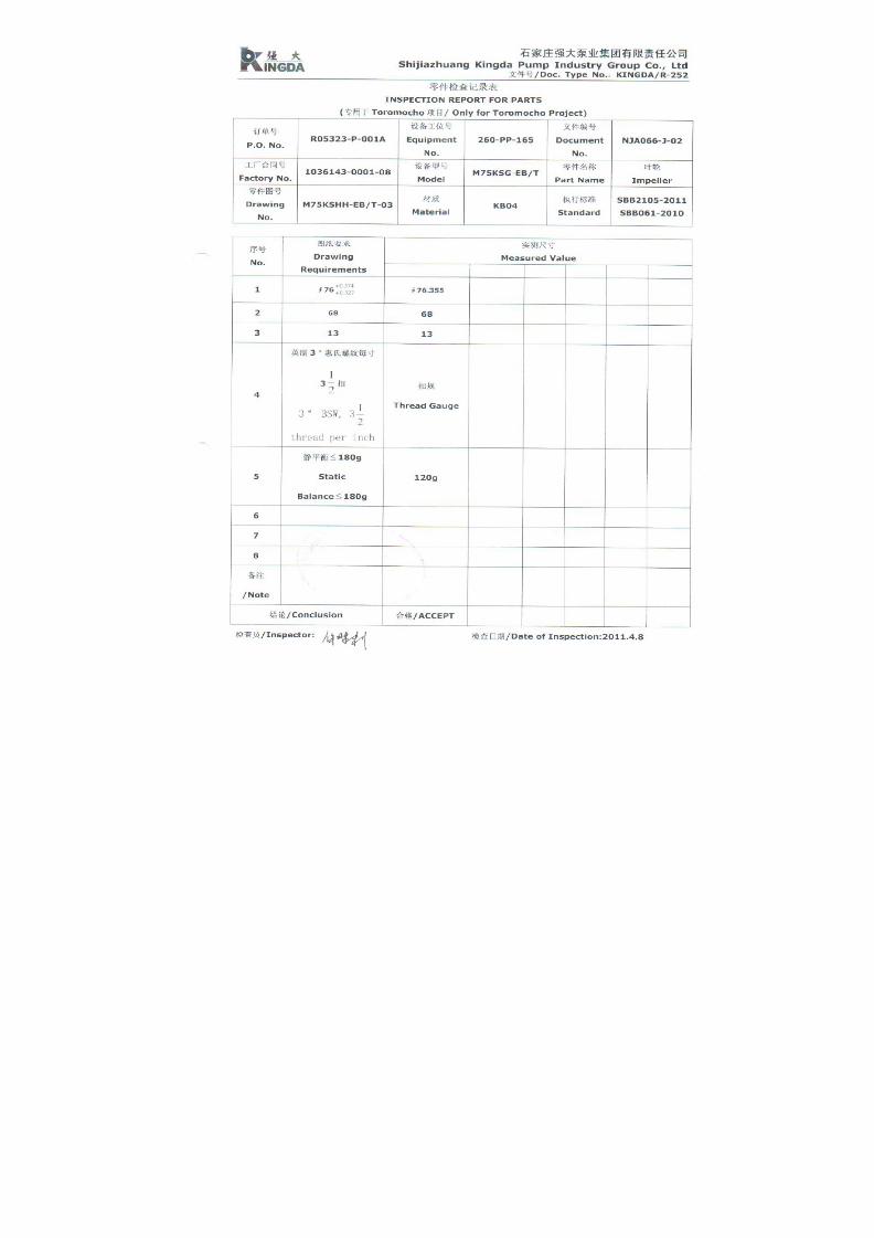
7/17/2019 R05323-P-001A-X009-0042.pdf
http://slidepdf.com/reader/full/r05323-p-001a-x009-0042pdf 378/463

7/17/2019 R05323-P-001A-X009-0042.pdf
http://slidepdf.com/reader/full/r05323-p-001a-x009-0042pdf 379/463

7/17/2019 R05323-P-001A-X009-0042.pdf
http://slidepdf.com/reader/full/r05323-p-001a-x009-0042pdf 380/463

7/17/2019 R05323-P-001A-X009-0042.pdf
http://slidepdf.com/reader/full/r05323-p-001a-x009-0042pdf 381/463

7/17/2019 R05323-P-001A-X009-0042.pdf
http://slidepdf.com/reader/full/r05323-p-001a-x009-0042pdf 382/463

7/17/2019 R05323-P-001A-X009-0042.pdf
http://slidepdf.com/reader/full/r05323-p-001a-x009-0042pdf 383/463

7/17/2019 R05323-P-001A-X009-0042.pdf
http://slidepdf.com/reader/full/r05323-p-001a-x009-0042pdf 384/463

7/17/2019 R05323-P-001A-X009-0042.pdf
http://slidepdf.com/reader/full/r05323-p-001a-x009-0042pdf 385/463

7/17/2019 R05323-P-001A-X009-0042.pdf
http://slidepdf.com/reader/full/r05323-p-001a-x009-0042pdf 386/463

7/17/2019 R05323-P-001A-X009-0042.pdf
http://slidepdf.com/reader/full/r05323-p-001a-x009-0042pdf 387/463

7/17/2019 R05323-P-001A-X009-0042.pdf
http://slidepdf.com/reader/full/r05323-p-001a-x009-0042pdf 388/463

7/17/2019 R05323-P-001A-X009-0042.pdf
http://slidepdf.com/reader/full/r05323-p-001a-x009-0042pdf 389/463
1
水泵 能试验程
Performance Test Procedure of Centrifugal Pump
一、试验前准备
1.确定试验项目;
2.确定试验依据、判定标准;
3.确定试验场地、选择试验台位;
1. Preparation before Test
1.1 Define items to be tested;
1.2 Define test criteria and acceptance standard
1.3 Define test field and select test bed
二、组装台位
1.安装泵、电机(减速机)、进出口管线; 2.接压力测量表、流量测量表、电测表;
3.接轴封水,电机装防水设备;
4.电机接动力线,试转,并贴转速感光纸;
2. Install Pump on Test Bed
2.1 Install pump, motor (if any, gear box), pump intake pipe and discharge pipe;
2.2 Connect pressure gauge, flow meter and electrical meters;
2.3 Connect shaft seal water, cover the motor with water-proof facilities;
2.4 Connect power supply cable with motor, make trial running, and paste
light-sensitive paper for speed.
三、试验
1.运转试验检查轴承温升、轴封泄漏、振动、噪声情况;
2.记录进出口压力、流量、电流、电压、功率、转速等数据;
3.绘制性能曲线;
4.对试验结果作出判定。
3. Test
3.1 Start the test, check rise in bearing temperature, leakage of shaft seal, vibration,
and noise;
3.2 Record pressure of suction and discharge, flow rate, current, voltage, power,
speed, etc;
3.3 Draft performance curve;
3.4 Make judgment on the test result.

7/17/2019 R05323-P-001A-X009-0042.pdf
http://slidepdf.com/reader/full/r05323-p-001a-x009-0042pdf 390/463

7/17/2019 R05323-P-001A-X009-0042.pdf
http://slidepdf.com/reader/full/r05323-p-001a-x009-0042pdf 391/463

7/17/2019 R05323-P-001A-X009-0042.pdf
http://slidepdf.com/reader/full/r05323-p-001a-x009-0042pdf 392/463

7/17/2019 R05323-P-001A-X009-0042.pdf
http://slidepdf.com/reader/full/r05323-p-001a-x009-0042pdf 393/463

7/17/2019 R05323-P-001A-X009-0042.pdf
http://slidepdf.com/reader/full/r05323-p-001a-x009-0042pdf 394/463

7/17/2019 R05323-P-001A-X009-0042.pdf
http://slidepdf.com/reader/full/r05323-p-001a-x009-0042pdf 395/463

7/17/2019 R05323-P-001A-X009-0042.pdf
http://slidepdf.com/reader/full/r05323-p-001a-x009-0042pdf 396/463

7/17/2019 R05323-P-001A-X009-0042.pdf
http://slidepdf.com/reader/full/r05323-p-001a-x009-0042pdf 397/463
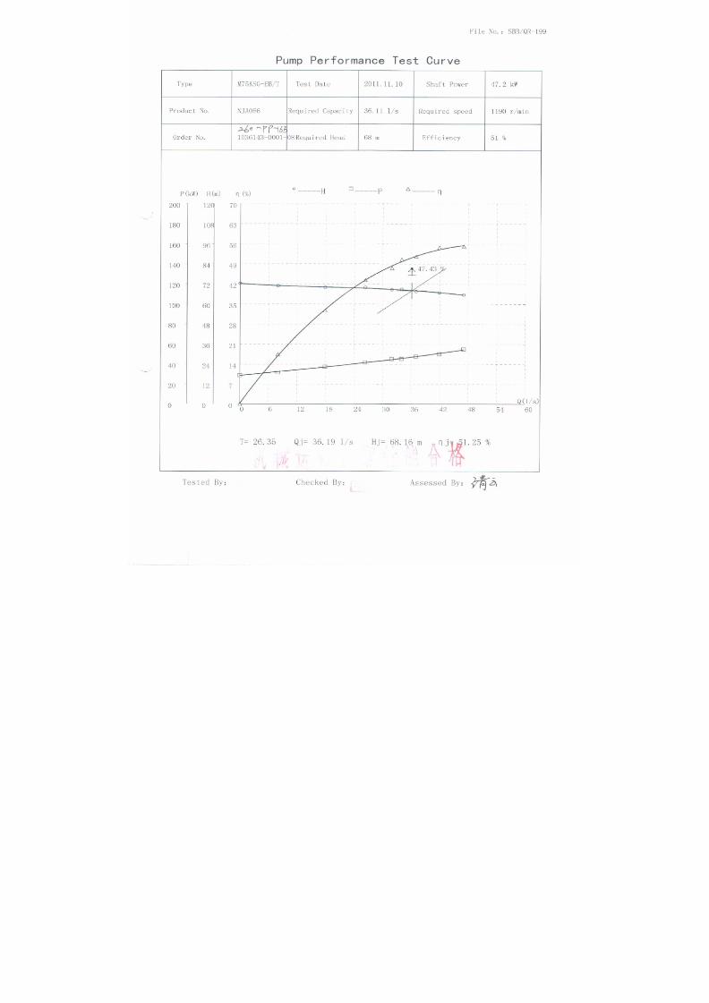
7/17/2019 R05323-P-001A-X009-0042.pdf
http://slidepdf.com/reader/full/r05323-p-001a-x009-0042pdf 398/463

7/17/2019 R05323-P-001A-X009-0042.pdf
http://slidepdf.com/reader/full/r05323-p-001a-x009-0042pdf 399/463

7/17/2019 R05323-P-001A-X009-0042.pdf
http://slidepdf.com/reader/full/r05323-p-001a-x009-0042pdf 400/463
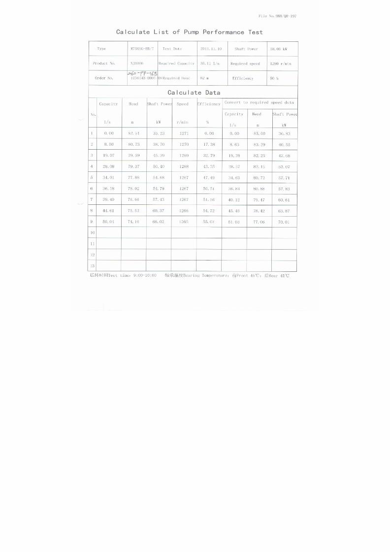
7/17/2019 R05323-P-001A-X009-0042.pdf
http://slidepdf.com/reader/full/r05323-p-001a-x009-0042pdf 401/463

7/17/2019 R05323-P-001A-X009-0042.pdf
http://slidepdf.com/reader/full/r05323-p-001a-x009-0042pdf 402/463

7/17/2019 R05323-P-001A-X009-0042.pdf
http://slidepdf.com/reader/full/r05323-p-001a-x009-0042pdf 403/463

7/17/2019 R05323-P-001A-X009-0042.pdf
http://slidepdf.com/reader/full/r05323-p-001a-x009-0042pdf 404/463

7/17/2019 R05323-P-001A-X009-0042.pdf
http://slidepdf.com/reader/full/r05323-p-001a-x009-0042pdf 405/463
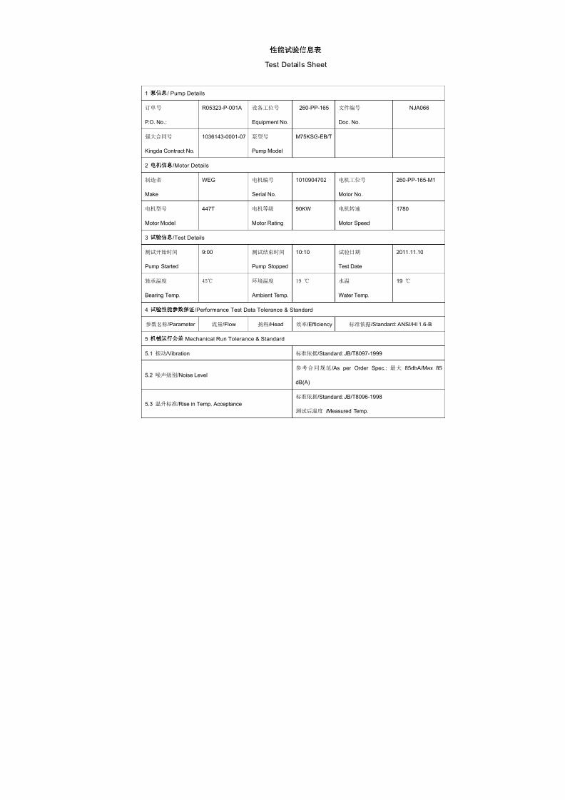
7/17/2019 R05323-P-001A-X009-0042.pdf
http://slidepdf.com/reader/full/r05323-p-001a-x009-0042pdf 406/463
性能试验 息表
Test Details Sheet
1 泵 息/ Pump Details
订单号
P.O. No.:
R05323-P-001A 设备工位号
Equipment No.
260-PP-165 文件编号
Doc. No.
NJA066
强大合同号
Kingda Contract No.
1036143-0001-07 泵型号
Pump Model
M75KSG-EB/T
2 电机 息/Motor Details
制造者
Make
WEG 电机编号
Serial No.
1010904702 电机工位号
Motor No.
260-PP-165-M1
电机型号
Motor Model
447T 电机等级
Motor Rating
90KW 电机转速
Motor Speed
1780
3 试验 息/Test Details
测试开始时间
Pump Started
9:00 测试结束时间
Pump Stopped
10:10 试验日期
Test Date
2011.11.10
轴承温度
Bearing Temp.
45 环境温度
Ambient Temp.
19 水温
Water Temp.
19
4 试验性能参数 证/Performance Test Data Tolerance & Standard
参数名称/Parameter 流量/Flow 扬程/Head 效率/Efficiency 标准依据/Standard: ANSI/HI 1.6-B
5机械运行公差
Mechanical Run Tolerance & Standard
5.1 振动/Vibration 标准依据/Standard: JB/T8097-1999
5.2 噪声级别/Noise Level
参考合同规范/As per Order Spec.: 最大 85dbA/Max 85
dB(A)
5.3 温升标准/Rise in Temp. Acceptance
标准依据/Standard: JB/T8096-1998
测试后温度 /Measured Temp.

7/17/2019 R05323-P-001A-X009-0042.pdf
http://slidepdf.com/reader/full/r05323-p-001a-x009-0042pdf 407/463
SERIES (M/R) KSH/KSG SLURRY PUMP
INSTALLATION, OPERATION AND MAINTENANCE
MANUAL
SHIJIAZHUANG KINGDA PUMP INDUSTRY GROUP CO.,LTD
2010

7/17/2019 R05323-P-001A-X009-0042.pdf
http://slidepdf.com/reader/full/r05323-p-001a-x009-0042pdf 408/463
Series (M/R) KSH/KSG Slurry PumpInstallation, Operation & Maintenance Manual
Shijiazhuang Kingda Pump Industry Group Co.,Ltd
1
Content
1. General Introduction…………………………….……………………………….…..2
2. Construction…………………………….…………………………………………………3
3. Installation…………………………………………………………………………………..6
4. Operation………………………………………………………………………….……….12
5. Maintenance……………………………………………………………………………….17
6. Possible Failures, Cause and Solutions……………………………….…………..20

7/17/2019 R05323-P-001A-X009-0042.pdf
http://slidepdf.com/reader/full/r05323-p-001a-x009-0042pdf 409/463
Series (M/R) KSH/KSG Slurry PumpInstallation, Operation & Maintenance Manual
Shijiazhuang Kingda Pump Industry Group Co.,Ltd
1 . GENERAL I N TRODUCT I ON
Series (M/R) KSH/KSG Pump is also called “High Efficiency Slurry Pump”. Because these pumps
are fitted with thick wear-resistant parts and heavy frame, so they are suitable to pump the slurry
of highly abrasion, high or low content and high head. During the max permissible working
pressure range, these pumps can be operated in serial. They also can transport the corrosive
slurries.
TYPE DEMONSTRATION:
2
Frame Type/Lubrication Type
Pump Type
Pump Discharge Diameter. (mm)
Metal Lined/Rubber Lined
Example: M200KSH (/KSG)-FA (/B)
M/R M for Metal Liner, R for Rubber Liner
200 Discharge Diameter is 200 mm
KSH Kingda Heavy-duty Slurry Pump
KSG Kingda High-head Slurry Pump
F Frame Type
A/B A for oil lubrication, B for grease lubrication

7/17/2019 R05323-P-001A-X009-0042.pdf
http://slidepdf.com/reader/full/r05323-p-001a-x009-0042pdf 410/463
Series (M/R) KSH/KSG Slurry PumpInstallation, Operation & Maintenance Manual
Shijiazhuang Kingda Pump Industry Group Co.,Ltd
2 . CONSTRUCT I ON
2.1 Pump Head (See Figure 1 and Figure 2)
Both Series (M/R) KSH/KSG metal-lined and rubber-lined pump have construction of
double-casing. They have the replaceable wear-resistant metal liner or rubber liner (including the
impeller, liner, frame plate, etc). Pump casing and cover are made of ductile cast iron; their
construction is vertically split and connected with the bolts. The casing is connected with the
frame with the bolt. When the suction of the pump is installed horizontally, the discharge can be
orientated in any 8 positions at 45° intervals. The front and rear cover plates of impeller have the
back vanes to decrease the leakage and raise the service life of the pumps. Viewing the pump
from the drive side, it should rotate clockwise.
Figure 1 Construction Drawing of MKSH/MKSG (Metal-lined)
Discharge diameter<40mm, open type impeller; Discharge diameter>40mm, enclosed type impeller.
1 Frame 2 Pump Cover 3 Cover Plate 4 Impeller
5 Liner 6 Pump Casing 7 Frame Plate 8 Packing Box
3

7/17/2019 R05323-P-001A-X009-0042.pdf
http://slidepdf.com/reader/full/r05323-p-001a-x009-0042pdf 411/463
Series (M/R) KSH/KSG Slurry PumpInstallation, Operation & Maintenance Manual
Shijiazhuang Kingda Pump Industry Group Co.,Ltd
Figure 2 Construction Drawing of RKSH/RKSG (Rubber-lined)
Discharge diameter<40mm, open type impeller; Discharge diameter>40mm, enclosed type impeller.
1 Frame 2 Pump Cover 3 Cover Plate (R) 4 Impeller
5 Cover Liner 6 Pump Casing 7 Frame Liner 8 Packing Box
2.2 Shaft Seal
There three types of shaft seals, packing seal, expeller seal and mechanical seal.
(1) Packing Seal: simple construction and easy maintenance. Shaft seal water is required. For the
condition which does not need the expeller seal, the packing seal can be used.
(2) Expeller Seal: Expeller seal can be used on the single stage pump or the first stage pump in
serial when the suction positive pressure is not more than the discharge pressure by 10%. The
expeller seal does not require the shaft seal water, and the slurry will not be diluted, which can
reach good sealing effect.
(3) Mechanical Seal: Mechanical seal features for highly wear resistant and shock resistance. It
can get non-leak sealing effect under various bad conditions, and be easily installed and
4

7/17/2019 R05323-P-001A-X009-0042.pdf
http://slidepdf.com/reader/full/r05323-p-001a-x009-0042pdf 412/463
Series (M/R) KSH/KSG Slurry PumpInstallation, Operation & Maintenance Manual
Shijiazhuang Kingda Pump Industry Group Co.,Ltd
5
replaced.
2.3 Transmission Part
During the bearing assembly of (M/R) KSH/KSG Pump, the pump has large diameter, high
stiffness and short cantilever, which will not bend and vibrate under the bad working conditions.
According to the different transmitted power, heavy single-row or double-row tapered roller
bearings can be selected. These bearings can stand the max axial and radial load of the pump. Oil
lubrication is used for the bearing. Seal cover, labyrinth bush, water-proof cover and guard cover
are fitted at the both sides of the bearing body, to prevent the impurities and water from entering
into the bearing and ensure the normal and safe operation of the bearing.

7/17/2019 R05323-P-001A-X009-0042.pdf
http://slidepdf.com/reader/full/r05323-p-001a-x009-0042pdf 413/463
Series (M/R) KSH/KSG Slurry PumpInstallation, Operation & Maintenance Manual
Shijiazhuang Kingda Pump Industry Group Co.,Ltd
3 . I N ST A LL AT I ON
3.1 Installation of Bearing Assembly (See Figure 3 and 4)
Heat the bearing inner ring before assembly, the temperature is not allowed to be over 120 and
the inner ring must contact the shaft shoulder closely. For the double row tapered roller bearing,
the inner ring, the outer ring and position bush is a package, not allowed to exchange with the
respective parts of the like bearings. For frame A, B, C, D, E, F, G, the bearing is single row
tapered roller type; when in assembly, adjust the pad at the bearing end cover to ensure the axial
clearance. The axial clearance should be in accordance with the following table:
Frame A B C D E F、G
Axial Clearance (mm) 0.05-0.15 0.1-0.2 0.15-0.25 0.18-0.28 0.4-0.6 0.5-0.6
For frame R, S, ST, T, TU, U, the bearing at the pump end is double row tapered roller type and
motor end is cylindrical roller bearing, there is no need to adjust the axial clearance for these
bearings.
Proper grease has been filled when assembling the bearing. The seal at the bearing end is
labyrinth ring or bush type; notice the relative arrangement of breach on the diametrical
direction when assembling the labyrinth ring.
Recommend using lithium base grease 2# or 3# and filled quantity as following:
Frame
Lubrication
B C D E F G
R.
RS
S.
ST
T.
TU
Drive End (g) 30 50 100 200 500 1150 200 500 1150
Driven End (g) 30 50 100 200 500 1150 400 1000 2300
6

7/17/2019 R05323-P-001A-X009-0042.pdf
http://slidepdf.com/reader/full/r05323-p-001a-x009-0042pdf 414/463
Series (M/R) KSH/KSG Slurry PumpInstallation, Operation & Maintenance Manual
Shijiazhuang Kingda Pump Industry Group Co.,Ltd
Figure 3 Constructions Drawing of R, S, ST, TU, T, U Frame Bearing Assembly
1 Labyrinth Bush 2 Oil Cup 3 Bearing Body 4 Bearing
5 End Cover 6 End Cover Seal Pad 7 Shaft
Figure 4 Construction Drawing of A,B,C,D,E,F,G Frame Bearing Assembly
1 Labyrinth Bush 2 Oil Cup 3 Grease Blocker 4 Bearing Body
5 Bearing 6 Adjusting Pad 7 End Cover 8 Shaft
3.2 Installation of Shaft Packing Seal
Shaft packing seal assembly includes packing box, shaft sleeve, position bush, seal ring, packing,
packing pad, lantern ring, front lantern ring and packing gland. Packing seal assembly is divided
into lantern ring structure and front lantern ring structure. Front lantern ring structure is the
standard-installed type, and you can see Figure 5 (1) and Figure 5 (2) for the installation drawing.
Lantern ring structure should be used for the condition of suction, for example of installation way
7

7/17/2019 R05323-P-001A-X009-0042.pdf
http://slidepdf.com/reader/full/r05323-p-001a-x009-0042pdf 415/463
Series (M/R) KSH/KSG Slurry PumpInstallation, Operation & Maintenance Manual
Shijiazhuang Kingda Pump Industry Group Co.,Ltd
in Figure 6 (1) and (2). Take notice that the seal ring must be in the right position between shaft
sleeve and position bush, and the shaft sleeve and impeller.
Figure 5 (1) and Figure 6 (1) are the construction drawing for the pump of discharge diameter
less than 150mm;
Figure 5 (2) and Figure 6 (2) are the construction drawing for the pump of discharge diameter
more than 500mm.
Selection of the packing: when the working pressure of the pump is below 1MPa (10kgf/cm2),
asbestos fibers dip mica packing is usually used; asbestos fibers soaked PTFE packing is usually
used when the pressure is higher than 1MPa (10kgf/cm2) or pumping the corrosive slurry.
Figure 5(1) Packing Seal Construction
Standard Type
Figure 6(1) Packing Seal Construction
For Suction-Up Condition
1 Shaft Sleeve 2 Packing 1 Shaft Sleeve 2 Packing
3 Packing Box 4 Front Lantern Ring 3 Packing Box 4 Lantern Ring
5 Seal Ring 6 Locating Bush 5 Seal Ring 6 Locating Bush
7 Packing Pad
8
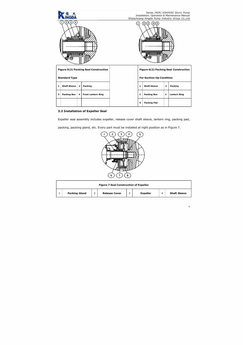
7/17/2019 R05323-P-001A-X009-0042.pdf
http://slidepdf.com/reader/full/r05323-p-001a-x009-0042pdf 416/463
Series (M/R) KSH/KSG Slurry PumpInstallation, Operation & Maintenance Manual
Shijiazhuang Kingda Pump Industry Group Co.,Ltd
9
Figure 5(2) Packing Seal Construction
Standard Type
Figure 6(2) Packing Seal Construction
For Suction-Up Condition
1 Shaft Sleeve 2 Packing 1 Shaft Sleeve 2 Packing
3 Packing Box 4 Front Lantern Ring 3 Packing Box 4 Lantern Ring
5 Packing Pad
3.3 Installation of Expeller Seal
Expeller seal assembly includes expeller, release cover shaft sleeve, lantern ring, packing pad,
packing, packing gland, etc. Every part must be installed at right position as in Figure 7.
Figure 7 Seal Construction of Expeller
1 Packing Gland 2 Release Cover 3 Expeller 4 Shaft Sleeve

7/17/2019 R05323-P-001A-X009-0042.pdf
http://slidepdf.com/reader/full/r05323-p-001a-x009-0042pdf 417/463
Series (M/R) KSH/KSG Slurry PumpInstallation, Operation & Maintenance Manual
Shijiazhuang Kingda Pump Industry Group Co.,Ltd
5 Seal Ring 6 Packing 7 Lantern Ring 8 Packing Pad
3.4 Installation of Mechanical Seal
Mechanical seal assembly includes Cartridge type mechanical seal, seal box, seal ring, etc.
Strictly install the mechanical seal according to the Manual. See Figure 8 for construction.
Figure 8 Construction of Mechanical Seal
1 Seal Box 2 Seal Ring 3 Mechanical Seal
3.5 Installation of Pump Head
Firstly fit the pump body on the frame, then put the shaft seal assembly into the pump body; fit
the rear guard plate and impeller with rear hanging pipe and rear set nut; fit the liner with the
hanging beam and use the bolts to press the liner against the pump body; fit the front guard the
plate into the pump cover, bolt the pump cover, front plate together with the pump body and
fasten all the bolts and nuts. For rubber liner pump, the front liner should be firstly put into the
pump cover and fasten the bolts, then assembly the pump body and pump cover; coat the soapy
water and rubber lubricant at the contact surface for the easy assembly; take notice that the seal
pads should be put at the right position and compressed; to assure the correct position and easy
assembly, the rear guard plate and rear liner hang pipe *302, rear guard plate and rear liner
position nut *302 and liner hanging beam *304 can be used. Following Figures show the
10

7/17/2019 R05323-P-001A-X009-0042.pdf
http://slidepdf.com/reader/full/r05323-p-001a-x009-0042pdf 418/463
Series (M/R) KSH/KSG Slurry PumpInstallation, Operation & Maintenance Manual
Shijiazhuang Kingda Pump Industry Group Co.,Ltd
methods.
The pump with ST, T and TU has release ring; before dismantling, the three hex bolts should be
removed and screw them into thither bolt hole on the release ring to jack the three pressure pad
on the shaft to loose the impeller.
Figure 9
1. Rear Guard Plate and Rear Liner Hang Pipe x302
2. Rear Guard Plate and Rear Liner Setting Nut x303
3. Liner Hang Beam x304
11

7/17/2019 R05323-P-001A-X009-0042.pdf
http://slidepdf.com/reader/full/r05323-p-001a-x009-0042pdf 419/463
Series (M/R) KSH/KSG Slurry PumpInstallation, Operation & Maintenance Manual
Shijiazhuang Kingda Pump Industry Group Co.,Ltd
12
4 . OPERAT I ON
4.1 Startup
Check the whole machine unit as following procedure before start up:
(1): The pump should be installed on the solid base to bear the whole pump weight to absorb the
vibration and fasten all the foundation bolts.
(2): The pipeline and valves should be separately supported. There is seal pad at the pump flange.
Notice that the pump metal liner may be higher than flange surface when fastening the bolts, and
the bolts should be not over-fastened to avoid damaging the seal pad.
(3): Rotate the pump shaft in accordance with the pump rotation direction, the shaft should drive
the impeller without the friction; if not, the impeller clearance should be adjusted.
(4): Check the motor rotation direction to make sure it can drive the pump rotate toward the
arrow. Reverse rotation may cause the impeller screw stripped and damage the pump, so it’s
forbidden.
(5): For direct coupling drive, the pump shaft and motor shaft should be strictly centered. The
pump shaft and motor shaft should be in parallel for the belt transmission and adjust the pulley
position to make it vertical to the belt. For the pulley unit of SPA Type andSPA
SPB Type, SPB Type
andSPB
SPC Type, the adjustment of the pulley should reach the requirements of α1=α2 in Figure 10.
(6): A short removable pipe should be fit at the suction of the pump, its length is enough to
disassemble the pump cover, replace the wearing parts and inspect the pump. See the Outline
Dimensional Drawing for the length of this short pipe.
(7): Check shaft seal: for the pumps of expeller seal, when the oil cup is fit with the release gland,
the lubricating grease should be filled through the oil cup; and Sodium-calcium grease is
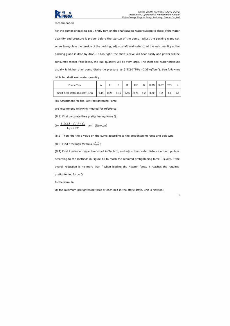
7/17/2019 R05323-P-001A-X009-0042.pdf
http://slidepdf.com/reader/full/r05323-p-001a-x009-0042pdf 420/463
Series (M/R) KSH/KSG Slurry PumpInstallation, Operation & Maintenance Manual
Shijiazhuang Kingda Pump Industry Group Co.,Ltd
recommended.
For the pumps of packing seal, firstly turn on the shaft sealing water system to check if the water
quantity and pressure is proper before the startup of the pump; adjust the packing gland set
screw to regulate the tension of the packing; adjust shaft seal water (that the leak quantity at the
packing gland is drop by drop); if too tight, the shaft sleeve will heat easily and power will be
consumed more; if too loose, the leak quantity will be very large. The shaft seal water pressure
usually is higher than pump discharge pressure by 3.5X10⁻²MPa (0.35kgf/cm2). See following
table for shaft seal water quantity:
Frame Type A B C D E.F G R.RS S.ST T.TU U
Shaft Seal Water Quantity (L/s) 0.15 0.25 0.35 0.55 0.70 1.2 0.70 1.2 1.6 2.1
(8) Adjustment for the Belt Pretightening Force
We recommend following method for reference:
(8.1) First calculate thee pretightening force Q:
Q=2
1
21 )5.2(510mv
V Z C
C PC +
××
×− (Newton)
(8.2) Then find the e value on the curve according to the pretightening force and belt type;
(8.3) Find f through formula f=e
.
L’
100 ;
(8.4) Find R value of respective V-belt in Table 1, and adjust the center distance of both pulleys
according to the methods in Figure 11 to reach the required pretightening force. Usually, if the
overall reduction is no more than f when loading the Newton force, it reaches the required
pretightening force Q.
In the formula:
Q: the minimum pretightening force of each belt in the static state, unit is Newton;
13

7/17/2019 R05323-P-001A-X009-0042.pdf
http://slidepdf.com/reader/full/r05323-p-001a-x009-0042pdf 421/463
Series (M/R) KSH/KSG Slurry PumpInstallation, Operation & Maintenance Manual
Shijiazhuang Kingda Pump Industry Group Co.,Ltd
f: Overall reduction of belt, unit is mm
C1: Angle coefficient is about 0.9
C2: Operation coefficient is about 1.4
L′: Center distance of pulleys
P: Motor Rated Power, KW
Z: V-Belt Quantity
V: linear velocity, m/s
m: Centrifugal force coefficient (see Figure 1)
e: Reduction e of each 100mm hang length, see Figure 11.
Table 1
Type SPA SPB SPC SPZ
R (N) 60 90 120 30
m 0.12 0.20 0.38 0.08
Adjust the V-belt till the final pretightening force is the minimum when the load is at max; when
several belts are used at the same time, the circumference of each belt should be basically the
same to assure the equal force.
Figure 10
14

7/17/2019 R05323-P-001A-X009-0042.pdf
http://slidepdf.com/reader/full/r05323-p-001a-x009-0042pdf 422/463
Series (M/R) KSH/KSG Slurry PumpInstallation, Operation & Maintenance Manual
Shijiazhuang Kingda Pump Industry Group Co.,Ltd
Figure 11
After adjustment of the V-belt, check if the impeller can rotate normally again; if possible, start
the pump with clear water (before it begins to pump the slurry); turn on the suction pipe valve,
start the motor, check the pressure and flow quantity at the suction and discharge, check the
leakage at the packing. If the packing heats, loose the packing gland bolts to make the leakage
bigger; adjust the leakage to the specified value till the packing run-in with the shaft.
4.2 Operation
(1): Periodically check the pressure and flow quantity of shaft seal water, and adjust the packing
gland and replace the packing during the operation to assure small quantity of clean water
passing through the shaft.
15

7/17/2019 R05323-P-001A-X009-0042.pdf
http://slidepdf.com/reader/full/r05323-p-001a-x009-0042pdf 423/463
Series (M/R) KSH/KSG Slurry PumpInstallation, Operation & Maintenance Manual
Shijiazhuang Kingda Pump Industry Group Co.,Ltd
16
(2): Periodically check the frame. If the bearing heats at the beginning of the operation, shut
down the pump till the bearing become cool, then run it. If the bearing heats seriously and
temperature keep rising, the frame must be disassembled and examined for the cause. Usually
the impurity contained in the lubricating oil can cause the heating, so the bearing oil should be
proper and clean, and replaced periodically.
(3): The pump performance will become poorer and the efficiency will become lower with the
larger and larger clearance between impeller and front guard plate. So adjust the impeller timely
to keep the proper clearance to make the pump run in high efficiency. When the wear situation of
the pump is too bad to meet the requirements of the system, the wear parts should be replaced.
4.3 Shutdown of Pump
Let the pump to transport the clear water for some before the shutdown to clean the slurry left
inside the pump, then stop the pump, valve, packing seal water or mechanical seal water in order.
7/17/2019 R05323-P-001A-X009-0042.pdf
http://slidepdf.com/reader/full/r05323-p-001a-x009-0042pdf 424/463
Series (M/R) KSH/KSG Slurry PumpInstallation, Operation & Maintenance Manual
Shijiazhuang Kingda Pump Industry Group Co.,Ltd
17
5 . MA I NTENAN CE
For the safe run of pump, attention must be paid to the normal maintenance as following aspects:
5.1 Maintenance of shaft seal:
For the packing seal pump, periodically check the water pressure and water quantity of shaft
packing seal. Always keep small quantity of clear water flow along with the shaft, periodically
adjust the packing gland, check and replace the packing. The shaft seal water pressure and
quantity should in accordance with the above requirements. Periodically fill the oil into the oil cup
for the expeller seal pump to lubricate the inside packing.
5.2 Adjustment of impeller:
To assure the high-efficiency of the pump, the clearance between the impeller and the front guard
plate; the clearance between impeller and front guard plate of metal liner pump should be
0.5-1mm, the clearance between the impeller and front liner should be equal to that between
impeller and rear liner.
Before adjusting the clearance, the pump should be stopped firstly, then loose the bolts of
bearing assembly and screw the nut of adjusting bolts to make the bearing assembly move
forward, at the same time, rotate the pump as per the arrow by hands till the impeller friction
with the front guard plate; for the metal liner pump, loose the nut (which was fastened) by half
circle, then fasten the nut on the adjusting bolt to make the bearing assembly move backward,
the clearance between the impeller and front guard plate should be 0.5-1mm; for the rubber liner
pump, adjust the nut of the adjusting bolts to make the bearing assembly to move forward to
contact with the front guard sleeve, then move the bearing assembly back to contact with the
back liner, and measure the total movement distance, make the half of this distance as the

7/17/2019 R05323-P-001A-X009-0042.pdf
http://slidepdf.com/reader/full/r05323-p-001a-x009-0042pdf 425/463
Series (M/R) KSH/KSG Slurry PumpInstallation, Operation & Maintenance Manual
Shijiazhuang Kingda Pump Industry Group Co.,Ltd
18
clearance of the impeller and front liner; assure the correct clearance of impeller and front and
back liner by adjusting bearing assembly position through the adjusting bolts.
After the adjustment, check if the impeller can rotate normally before startup, if bearing
assembly compress bolts and adjusting bolts are tightened; then start the pump.
5.3 Lubricating of Bearing
Correct assembly, proper lubricating and in-time maintenance will make the service life of
bearing assembly longer. Periodically check the bearing assembly, bearing and lubricant and
interval should not be over than 12 month. Fill the lubricating grease at regular intervals in
operation, the filling interval and filling quantity are relative to the pump speed, bearing size,
continuous operation time, shutdown and startup times, environmental condition and
temperatures; excess grease will cause the heating of bearing. Refer to following table for proper
lubricating schedule:
5.4 Standby pump should be rotated by 1/4 circle by hands to make the bearing stand static load
and vibration evenly

7/17/2019 R05323-P-001A-X009-0042.pdf
http://slidepdf.com/reader/full/r05323-p-001a-x009-0042pdf 426/463
Series (M/R) KSH/KSG Slurry PumpInstallation, Operation & Maintenance Manual
Shijiazhuang Kingda Pump Industry Group Co.,Ltd
Lubrication Schedule (in hours)
19
Note: Above Schedule is only applied for the normal working condition.
During the bearing assembly, the internal plug is to fill the bearing grease, and the external oil
cup is to clean the labyrinth seal. Besides the regular filling of grease, it’s also to fill the grease to
the oil cup to keep the labyrinth seal clean.
Bearing Speed (rpm)Frame
Type
Grease
Quantity 200 300 400 600 800 1000 1200 1800 2000
B 12 3000 2400 1800 1500 1000
C 18 3600 2400 1800 1600 1200 900
D 28 2500 2000 1500 1200 800 500
E 44 5000 3600 2200 1600 1100 800 500
F 71 7000 4200 2000 1800 1200 700 400
R.RS 102 3000 2000 1400 1000 600 400 100
S.ST 132 3800 28000 1500 900 500 300
T.TU 304 4800 3000 1800 900 400
Pump
End
U 621 4000 2400 1500 500
R.RS 61 8000 4800 3500 2800 2200 1500 900
S.ST 74 8000 6000 3600 2400 1600 1200
T.TU 133 8000 7000 4500 2500 1500
Motor
End
U 192 7000 6000 4000 2000

7/17/2019 R05323-P-001A-X009-0042.pdf
http://slidepdf.com/reader/full/r05323-p-001a-x009-0042pdf 427/463
Series (M/R) KSH/KSG Slurry PumpInstallation, Operation & Maintenance Manual
Shijiazhuang Kingda Pump Industry Group Co.,Ltd
20
6 . POSS I B LE FA I LURES , CAUSE AN D SOLUT I ONS
Failure Cause Solutions
Leak at the suction pipe or packing Block the leak
Wrong rotation direction Change the rotation direction
Impeller is broken Replace the new impeller
Not pump the liquid
Suction pipe is blocked Remove the block
Packing gland is to tight and packing heats Loose the packing gland bolts
Friction inside the pump Adjust the clearance
Bearing is broken Replace the bearing
Transmission belt is too tight Adjust the belt
Too large flow quantity Adjust the pump running conditions
High rotation speed, large proportion Adjust the rotation and proportion
Shaft Power is to high
Misalignment or nonparallel of motor shaft and Adjust the motor shaft and pump shaft
Excessive or too little of bearing lubricating oil Oil quantity should be as per
Impurities is contained in the lubricating oil Replace the new lubricating oilOverheat of bearing
Bearing is broken Replace the new bearing
Misalignment or nonparallel of motor shaft and Adjust the motor shaft and pump shaft
Shaft is bent Replace a new shaft
Friction inside the pump or the imbalance of Decrease the friction and replace a new
Foreign matter inside the bearing Clean the bearing
Service life of bearing is short
Unreasonable assembly of bearing Replace the bearing or reassemble the
Serious abrasion of packing Replace the new packing
Serious abrasion of shaft sleeve Replace the new shaft sleeveSerious leakage at the packing
Seal water is not clean Replace the clean seal water
Bearing is broken Change new bearing
Impeller is not in balance Change new impeller
Air entered into suction pipe, block Remove the air and block
Uneven flow, pump empty Improve the feeding condition
Abnormal noise and excessive vibration
of pump
Bad foundation Strength the foundation

7/17/2019 R05323-P-001A-X009-0042.pdf
http://slidepdf.com/reader/full/r05323-p-001a-x009-0042pdf 428/463
INSTALLATION,OPERATION ANDMAINTENANCE
INSTRUCTION MANUALFOR INDUCTION
MOTORSFrame sizes 143/5T to 586/7
WEG EXPORTADORA S.A.
Av. Prefeito Waldemar Grubba, 300089256-900 - J aragua do Sul - SC - BRAZIL
Phone 55 (47) 3372-4000 - Fax 55 (47) 3372-4060http://www.weg.com.br
Transforming Energy into Solutions
0 2 8 0 . 1
5 1 5 / 0 3 . 2
0 0 6

7/17/2019 R05323-P-001A-X009-0042.pdf
http://slidepdf.com/reader/full/r05323-p-001a-x009-0042pdf 429/463
THIS MANUAL IS INTENDED TO SUPPLY IMPORTANT TOPICS THAT MUST BE FOLLOWED DURING
TRANSPORTATION, INSTALLATION, OPERATION AND MAINTENANCE OF WEG MOTORS. THEREFORE, WE RECOMMEND READING CAREFULLY THIS MANUALBEFORE INSTALLING AND OPERATING THE MOTOR.
TO ENSURE PHYSICAL INTEGRITY TO THE OPERATION AND MATERIAL PROTECTION, ALL
INFORMATION INCLUDED IN THIS MANUAL MUST BE STRICTLY FOLLOWED.
I
INDEX
1. HANDLI NG AND TRANSPORTATION 2. RECEIVING INSPECTION 3. STORAGE 4. INSTALLATION
4.1 - Safe ty 4.2 - Op e ra ti ng Co n di ti o ns 4.3 - Fo u nd a ti on 4.4 - D ra in H o le s 4.5 - B alan ce 4.6 - Al ig nm e nt 4.7 - C ou p li ng s 4.8 - El ec t r ic a l Co n ne c t io n 4.9 - St ar ti ng Me th o ds 4 .10 - P ro tec t i on Dev i ce
4.11 - Star t -Up 5. MAINTENANCE
5.1 - Lubrication 5.1 .1 - Mach ines wi thout Grease Nipp les 5.1.2 - Mac hines Fitted with G rease Fitting 5.1.3 - Com patibil ity of MOBIL Polirex EM
grease with other types of grease 5 .2 - A ssemb ly and D i s as semb l y
6. SPARE PARTS 7. VARIABLE FREQUENCY DRIVE MOTORS
7.1 - St an d ar d Mo t or s 7 .2 - I nv er te r Du t y Mo to r s 7 .3 - Bear in g I n su l at io n
8. ADDITIONAL INSTRUCTIONS 8 .1 - Haza rd ou s Ar ea Mo to r s
8.1 .1 - Gene ra l 8.1.2 - Instal lat ion 8.1 .3 - Chec k ing and main tenanc e 8.1.4 - Explosion Proof M otor Repairs
9. WARRANTY TERMS
Purchasing date:
Supplier’s name
Invoice/Order number:
Customer’s name and phone:
Failure description:

7/17/2019 R05323-P-001A-X009-0042.pdf
http://slidepdf.com/reader/full/r05323-p-001a-x009-0042pdf 430/463
Lifting devices, when supplied, are designed only to supportthe motor. If the motor has two lifting devices then a double chainmust be used to lift it.Lifting and lowering must be done gently without any shocks, toavoid bearing damaged.
DURING TRANSPORTATION, MOTORS FITTED WITH ROLLER OR ANGULAR CONTACT
BEARINGS ARE PROTECTED AGAINST BEARING DAMAGES WITH A SHAFT LOCKING DEVICE
MOTORS MUST NOT BE LIFTED BY THE SHAFT,
BUT BY THE EYEBOLTS SPECIFIC FOR SUCH
PURPOSE
THIS LOCKING DEVICE MUST BE USED ON ANY FURTHER MOTOR TRANSPORTATION, EVEN
WHEN THIS MEANS TO UNCOUPLE THE MOTOR FROM THE DRIVEN MACHINE
I
I
I
2. RECEIVING INSPECTION
When receiving the motor, check if any damage has occurredduring transportation.
If anything has been noticed, notify immediately the carrier, theinsurance company and WEG.Failure in giving notice to the carrier, to the insurance companyand to WEG may result in loosing product warranty.
Do not remove the existing protecting grease from the shaft end,nor the stoppers or plugs that close the terminal box holes, if any.
These protection items must be kept in place until the finalinstallation has been concluded.After being removed from the package, a complete visualinspection on the motor should be made:
1 - HANDLING AND TRANSPORTATIONFecha de compra:
Nombre del proveedor:
Número de la factura o pedido:
Nombre y número telefónico del cliente:
Descripción de la falla:

7/17/2019 R05323-P-001A-X009-0042.pdf
http://slidepdf.com/reader/full/r05323-p-001a-x009-0042pdf 431/463
If motors are not immediately installed, they must be stored indry areas, free of dust, vibrations, gases, corrosive smokes, underconstant temperature and in normal position free from othermaterials.
Motor storage temperature must remain between 41ºF (5ºC) to140ºF (60ºC), with relative humidity not exceeding 50%.
If motors are stored for more than two years, bearings must bereplaced or the lubrication grease must be totally removed aftercleaning.
Single-phase motors when kept in stock for 2 years or moremust have their capacitors replaced (if any).
WEG recommends to rotate the shaft (by hands) at least once a
month, and to measure the insulation resistance before installingit, if motors are stored for more than 6 months or when subjectto high humidity areas.
If motor is fitted with space heaters, it is recommended to switchthem on during storage period if the relative humidity exceeds50%.If motor remains in stock for a long period without having thespace heaters switched-on or when installed but not in operation,moisture/water inside the motor may condense. On these cases,water must be drained by removing the threaded drain plugs.When drainage is done, switch-on the space heaters and makesure the motor is completely dry, then reinstall the drain plugs toensure proper Degree of Protection (see figure 1).
The space heaters should NEVER be energized while motor isrunning.
3 - STORAGE
ü Check if any damage has occured during transportation.ü Check nameplate data.ü Rotate shaft with the hand to make sure it is running freely.ü Make sure the motor was not exposed to excessive dirt andmoisture during transportation and storage.
9. TERMINOS DE GARANTIA
WEG of rec e garantía co nt ra defec tos d e fabr icac ión o d e materiales para sus p roduc tos, por un p eríodo de 18 me ses,con tados a partir de la fecha de la emisión de la factura por parte de fáb rica o d el distribuidor/revendedor, teniendo c omo límite 24 meses d e la fecha de fabric ación indep endiente de la fecha de instalac ión del motor, siemp re y cuand o hayan sido sat isfechos los siguientes requis i tos:
- Transpor te , manoseo y a lmacenamiento adecuados; - I n s t a la c i ón co r r e c t a y en cond i c i o ne s amb i e n t a l e s espec íficas y sin presenc ia de g a ses corrosivos; - Operación dentro de los límites de la capacid ad del moto r; - Realización periódica del d ebido m antenimiento prevent ivo; - Realización de reparaciones y/o modif icaciones al producto original efectuada solo por los agentes autorizados de la Red de Asiste nc ia Técn ic a WEG; - Entregar el producto a l proveedor en el caso de ocurr i r una fal la c on rec lam aci ón d e g arant ía en un p eríod o m ínim o su f i c i en te p a ra iden t i f i ca r la causa d e la an oma lía y su conven ien te repa rac ión ; - Dar av iso inmed ia to a WEG, por par te de l c l ien te , de los defectos detec tados y que los mismos sean poster iormente ana l i za do s po r WEG co mo c au sado s po r de f e c t o s de fabr icac ión.La garant ía no inc luye los servicios de desmo ntaje d el moto r en las ins ta lac iones de l c l ien te , cos to s de t ranspor te de l produc to y gastos de traslado, alojamiento y alimentación del person al de Asistencia Técnic a cuand o sean solic itados p or e l c l ien te .Los ser vicio s en ga rantía serán pre stad os exc lusivam ente e n talleres d e Asistenc ia Técn ica Aut orizada WEG o en la prop ia fábric a.Se excluyen de esta gara ntía los c ompon entes c uya vida útil,en u so no rmal, sea inferior a l períod o d e ga rantía ot orga do po r WEG las repa rac ion es o subs t i t u c iones de p iezas o pro duc t os , a cr i te r io de WEG o su Asis ten c ia Técn ica Autori zada, no pro rrog ará el plazo de g arantía orig inal.La presente g arantía se limita al pro duc to entreg ado, no sien do respon sable WEG po r daños a person as, a terc eros, a o tros
equipos e instalaciones, ut i l idades que se dejen de ob tener o cu alquier otro daño eme rgente o c onsec uente.

7/17/2019 R05323-P-001A-X009-0042.pdf
http://slidepdf.com/reader/full/r05323-p-001a-x009-0042pdf 432/463
Insulation Resistance Checking
Disconnect motor from power supply before making anyinsulation resistance measurement.
To avoid electric discharge risks, discharge the terminals rightafter performing the measurement.
Measure the insulation resistance before operating the motorand/or when there is any sign of moisture in the winding.
The resistance measured at 77ºF (25ºC) must be:
Ri ≥
(20 x U) / (1000 + 2P) [MΩ](measured with a MEGGER at 500 V d.c.)where U = voltage (V); P = power (kW).
If the insulation resistance detected is less than 2 mega ohms, thewinding must be dried according to the following procedure:Warm it up in an oven at a minimum temperature of 176ºF (80ºC)increasing 41ºF (5ºC) every hour until reaching 105ºC (221ºF),remaining under this temperature for at least one hour.
Figure 1
P Las superficies de encaje de los motores a prueba de explosiónno deben ser mecanizadas y no es permitido utilizar entre ellasningún tipo de vedamiento, no descrito o suministrado por elfabricante. Los encajes deben ser solamente limpios y para evitarcorrosión o penetración de agua, los encajes pueden serengrasados con una fina manta de grasa de silicona.P Verificar si los componentes están exentos de rebabas, golpesy suciedad.P Observar si las piezas están en perfectas condiciones.P Lubricar superficialmente las guías de las tapas con aceiteprotector para facilitar el montaje.P Utilizar solamente martillo de material blando en la colocaciónde las piezas.P Verificar si todos los tornillos están bien apretados.P Utilizar sonda calibrada para verificar asiento de la caja deconexiones (menor de 0,05mm).
8.1.4 Reparos De Motores A Prueba De Explosión
El reparo de repuestos, directamente involucrados en laprotección contra riesgo de una explosión, debe ser realizadosin cualquier modificación al diseño original del motor.
Después del reparo, estos repuestos deben ser chequeados ycuando concluido, el taller de asistencia técnica debe hacer unadeclaración de todas las operaciones realizadas en el motorespecífico.
Para maiores informaciones, en México favor comunicarse a:
WEG México, S.A de C.V.Carretera J orobas-Tula Km 3.5,Mz.5, Lote 1, entre Lote 4 y 5
Fracc. Parque Indistrial Huehuetoca,Huehuetoca Estado de Méx., C.P 54680 Tel: (55) 5321-4243 y 61; Fax: (55) 5321-4262 y 94
e-mail: [email protected]
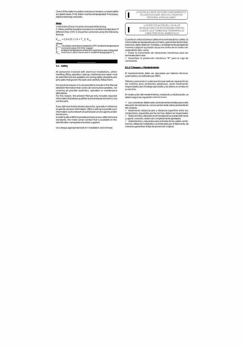
7/17/2019 R05323-P-001A-X009-0042.pdf
http://slidepdf.com/reader/full/r05323-p-001a-x009-0042pdf 433/463
Check if the stator insulation resistance remains constant withinaccepted values. If not, stator must be reimpregnated. If necessary,replace bearings and seals.
Note:
1) All drains (if any) must be removed while drying.2 - Measured the insulation resistance in ambient temperature. If different than 25ºC it should be corrected using the followingformula:
R(25°C) = [( K+25 ) / ( K + Ta )] . R (Ta)
Where:R
(25°C)insulation resistance related to 25ºC ambient temperature
K constant value 234.5 for copper T
aambient temperature where the resistance was measured
R(Ta)
resistance value measured in ambient temperature Ta
4. INSTALLATION
4.1 - Safety
All personnel involved with electrical installations, eitherhandling, lifting, operation, start up, maintenance or repair must
be well informed and updated concerning safety standards andprinciples that govern the work and carefully follow them.
For practical reasons, it is not possible to include in this Manualdetailed information that covers all constructive variables, norcovering all possible assembly, operation or maintenancealternatives.For this reason, the present Manual only includes requiredinformation that allows qualified and trained personnel to carryout the work.
If you still have further doubts about this, specially in referenceto specific product information, WEG is willing to provide suchinformation via its network of authorized service agents and/ordistributors.
In order to allow WEG to provide prompt service, within technicalstandards, the motor serial number that is available on theidentification nameplate should be supplied.
Use always appropriate tools for installation and removal.
LA INSTALACION DE MOTORES PARA AMBIENTES PELIGROSOS DEBE SER EJECUTADA POR
PERSONAL ESPECIALIZADO
LA ESPECIFICACION DEL LOCAL DE INSTALACION ES DE RESPONSABILIDAD DELCLIENTE, QUE TAMBIEN DETERMINARA LAS
CARACTERISTICAS AMBIENTALES
Cuando se utiliza el prensa cables en la entrada de los cables, lomismo debe ser apropiado para el motor y para el tipo de terminal,el prensa cables debe ser montado, completamente apretado demanera a adquirir la presión necesaria arriba de los anillos devedamiento, bien como:ü Evitar la transmisión de vibraciones mecánicas para losterminales del motor.ü Garantizar la protección mecánica “IP” para la caja deconexiones.
8.1.3 Chequeo y Mantenimiento
El mantenimiento debe ser ejecutado por talleres técnicosautorizados y acreditados por WEG.
Talleres y personal sin autorización que realicen reparación enlos motores para ambientes peligrosos, serán totalmenteresponsables por el trabajo ejecutado y los daños ocurridos ensu servicio.
En la ejecución del mantenimiento, instalación y relubricación, sedeben seguir las siguientes orientaciones:
ü Las conexiones deben estar correctamente cerradas para evitarelevación de resistencia, consecuentemente sobrecalentamientodel contactoü Aislamiento distancia-aire y distancia-superficie entre losconductores, requeridos por las normas, deben ser respectados
ü
Todos tornillos utilizados en el montaje de las partes del motory caja de conexión, deben ser completamente apretadosü Vedamientos y repuestos para entrada de los cables seránhechos utilizando materiales suministrados por el fabricante, demanera a garantizar el tipo de protección original
I
I

7/17/2019 R05323-P-001A-X009-0042.pdf
http://slidepdf.com/reader/full/r05323-p-001a-x009-0042pdf 434/463
MAKE SURE THAT ELECTRIC MOTORS ARE SWITCHED OFF BEFORE STARTING ANY MAINTENANCE SERVICE I
All rotating parts such as pulleys, couplings, outside fans, shaft,etc. must be protected against accidental contact.Motors must be protected against unexpected starts.When performing any maintenance service, disconnect the motorfrom the power supply. Make sure all accessories have been
switched off and disconnected.In order to prevent from penetrating dust and/or water into theterminal box, cable glands or threaded pipe in the lead holespassage must be installed. They must be of equal or higher IPrating than the motor.
LEAD CONNECTION INSULATION INSIDE THE TERMINAL BO X MUST BE DONE WITH AN INSULATING
MATERIAL COMPATIBLE WITH MOTOR THERMALCLASS WHICH IS SHOWN ON THE MOTOR
NAMEPLATE
I
If installation and safety instructions are not followed accordingly,warranty may be void.
4.2 - Operating Conditions
In general electric motors are designed for operation up to analtitude of 1000m above sea level for an ambient temperatureranging from -4ºF (-20ºC) to 104ºF (40ºC). Any variation is statedon the nameplate.
The recommended installation distance between air inlet fromthe motor and the wall should be at least ¼ of the air inlet diameter.A person should have enough room to carry out cleaning services.Machines that are cooled with ambient air, air inlet screens mustbe cleaned at regular intervals so as to ensure free air circulation.Warm air can not return to the motor.ü For vertically mounted motors with air inlet on top, the air
opening must be protected by a proper cover so as to avoiddropping of foreign materials on the motors.ü Considering that direct sun heat causes increase intemperature, externally installed motors should be alwaysprotected against weathering.
7.3– Aislamiento del rodamiento
Los motores Inverter Duty en las carcasas 504/5T y 586/7T* sonsuministrados con sistema de puesta a tierra entre el eje y la carcasaen el lado delantero. También, bajo pedido puede ser suministradocon rodamientos aislados.
Para otras líneas, en las carcasas 504/5T y 586/7T* cuando usadoscon convertidor de frecuencia es necesario sistema de puesta atierra entre el eje y la carcasa o rodamientos aislados.
* Otros tamaños de carcasas, bajo consulta.
8 – INSTRUCCIONES ADICIONALES
8.1 – Motores Para Areas de Riesgo
8.1.1 General
Además de las recomendaciones arriba, las siguientes tambiéndeben ser observadas:
Motores para áreas de riesgo son fabricados de acuerdo connormas específicas para estos ambientes.Motores suministrados para áreas de riesgo (áreas clasificadas)deben ser instalados en área que estén de acuerdo con lasespecificadas en la tarjeta de identificación del motor.
Notas:
ü Motores División I son también adecuados para la División IIü Motores de una especificada clase de temperatura son tambiénadecuados para ambientes con combustible de una clase detemperatura mayor (ejemplo, motores T4 son adecuados paraambientes de clase T3, T2, T1).
8.1.2 Instalación
La instalación debe seguir procedimientos elaborados por lalegislación local vigente.

7/17/2019 R05323-P-001A-X009-0042.pdf
http://slidepdf.com/reader/full/r05323-p-001a-x009-0042pdf 435/463
COMPARE THE CURRENT, VOLTAGE, FREQUENCY,SPEED, OUTPUT AND OTHER VALUES REQUIRED BY
THE APPLIC ATION WITH MOTOR NAMEPLATE INFORMATION
I
ODP MOTORS – Open motors (IP21, IP23) are machines designedfor operation in clean, dry areas, with enough air circulation forproper cooling. These motors should never be used in areas withflammable materials. Open motors may cause sparks and releasecast particles under any eventual insulation failure (short-circuit).
TEFC MOTORS – Totally enclosed motors are machines suitable tooperate in areas with moisture, dirt and/or corrosive materials eitherin enclosed or open environments.
4.3 - Foundation
Motors provided with feet must be installed on solid foundationsto avoid excessive vibrations.All motors must be fully fixed and aligned.
The purchaser is fully responsible for the foundation.Metal parts must be painted to avoid corrosion.
The foundation must be uniform and sufficiently strong to supportany shock. It must be designed in such a way to stop any vibration
originated from resonance.
Note: Considering that rotation direction is important for correctoperation, then check it carefully before connecting motor to theload.
4.4 - Drain Holes
Make sure drains are placed at the lower motor position when themounting configuration differs from that specified on the motorpurchase order.
4.5 – Balance
WHEN SPECIAL BALANCE IS REQUIRED,CONTACT THE FACTORY I
EL NO CUMPLIM IENTO DE ESTAS RECOMENDACIONES Y CRITERIOS CAUSA LA
PERDIDA DE GARANTIA DEL MOTOR
7.2 – Motores Inverter Duty
Motores con tensiones superiores a 575V e igual o menor que690V y alimentados por convertidor de frecuencia no necesitanfiltros caso sigan las especificaciones abajo:
I
( * ) I n f o r m a
d o p o r e
l f a b r i c a n
t e d e
l c o n v e r t i d o r .
ü Observar tensión dealimentación del conjuntoventilación forzada.
EL NO CUMPLIMIENTO DE ESTAS
RECOMENDACIONES Y CRITERIOS CAUSA LAPERDIDA DE GARANTIA
DEL MOTOR
I
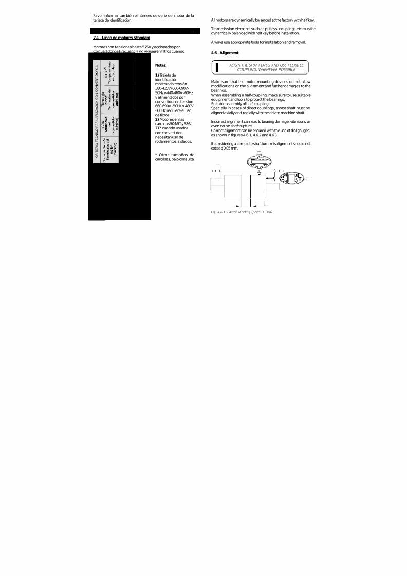
7/17/2019 R05323-P-001A-X009-0042.pdf
http://slidepdf.com/reader/full/r05323-p-001a-x009-0042pdf 436/463
All motors are dynamically balanced at the factory with half key.
Transmission elements such as pulleys, couplings etc must bedynamically balanced with half key before installation.
Always use appropriate tools for installation and removal.
4.6 – Alignment
ALIGN THE SHAFT ENDS AND USE FLEXIBLE COUPLING, WHENEVER POSSIBLE I
Make sure that the motor mounting devices do not allowmodifications on the alignment and further damages to thebearings.When assembling a half-coupling, make sure to use suitableequipment and tools to protect the bearings.Suitable assembly of half-coupling:Specially in cases of direct couplings, motor shaft must bealigned axially and radially with the driven machine shaft.
Incorrect alignment can lead to bearing damage, vibrations oreven cause shaft rupture.
Correct alignment can be ensured with the use of dial gauges,as shown in figures 4.6.1, 4.6.2 and 4.6.3.
If considering a complete shaft turn, misalignment should notexceed 0.05 mm.
Fig. 4.6.1 - Axial reading (p arallelism )
Favor informar también el número de serie del motor de latarjeta de identificación.
7 – MOTORES PARA USO CON CONVERTIDOR DE FRECUENCIA
7.1 – Línea de motores Standard
Motores con tensiones hasta 575V y accionados porConvertidor de Frecuencia no requieren filtros cuandoadoptados los criterios a seguir:
( * ) I n f o r m a
d o p o r e
l f a b r i c a n
t e d e
l c o n v e r t i d o r .
Notas:
1) Trajeta deidentificaciónmostrando tensión380-415V / 660-690V -50Hz y 440-460V - 60Hzy alimentados porconvertidor en tensión660-690V - 50Hz o 480V- 60Hz requiere el usode filtros.2) Motores en lascarcasas 504/5T y 586/
7T* cuando usadoscon convertidor,necesitan uso derodamientos aislados.
* Otros tamaños decarcasas, bajo consulta.

7/17/2019 R05323-P-001A-X009-0042.pdf
http://slidepdf.com/reader/full/r05323-p-001a-x009-0042pdf 437/463
Fig. 4.6.2 – Radial read ing (c onc entric ity)
Fig. 4.6.3 – Axial and radial readin g c ombined
The axial alignment (“E” dimension) between half couplingsshould be performed in accordance with manufacturer’srecommendations.
If required, WEG can offer its personnel duly trained as well as alaser equipment to make motor and driven machine alignment/
leveling.
Expansion effect of the components may change the alignment/leveling conditions during performance.
Notas:
ü Aunque la grasa Polyrex® EM (Mobil) sea compatible conlos tipos de grasa mencionados arriba, no recomendamos lamezcla con cualquier tipo de grasa.ü Si Ud. necesita utilizar otro tipo de grasa diferente de lasrecomendadas arriba, primeramente contacte con WEG.
LA UTILIZACION DE MOTORES NORMALES EN LOCALES Y/O APLICACIONES ESPECIALES DEBE
ESTAR PRECEDIDA DE UNA CONSULTA ALFABRICANTE DE GRASAS Y/O A WEG
I
5.2 - Desmontaje Y Montaje
ü El desmontaje y montaje del motor deberá ser hecho por
personal calificado, utilizando solamente herramientas ymétodos adecuados.ü Las garras del extractor de rodamientos deberán estar
aplicadas sobre la pista interna o sobre la tapa interior.ü Es esencial que el montaje de los rodamientos sea ejecutadoen condiciones de rigurosa limpieza, para asegurar un buenfuncionamiento y evitar daños. En el caso de colocarrodamientos nuevos, éstos deberán ser retirados de su embalajesolamente en el momento previo de su montaje al motor.ü Antes de instalar un rodamiento nuevo, es necesario verificarsi el alojamiento del mismo en el eje se encuentra exento derebabas o señales de golpes.ü Para montaje del rodamiento caliente sus partes internas conequipamiento apropiado – por inducción – o utilice herramientasapropiadas.
6. PARTES Y PIEZAS (REPUESTOS)
Al solicitar piezas para reposición, es conveniente indicar ladesignación completa del motor, así como el código del mismoque aparece marcado en la tarjeta de identificación.

7/17/2019 R05323-P-001A-X009-0042.pdf
http://slidepdf.com/reader/full/r05323-p-001a-x009-0042pdf 438/463
4.7 – Couplings
When using pulley or belt drive (coupling), follow theinstruction given below:
Remove shaft-locking device (if any) before installing the motor.
Belts must be tighten just enough to avoid slippage whenrunning, according to the specifications stated on the beltsupplier recommendation.
To make the installation of the pulley on the shaft easier, it isrecommended to heat up the pulley at 176ºF (80°C) and haveit mounted at hot, using suitable tools.
To avoid bearing and shaft end damage, mounting anddismounting of pulleys must be made with suitable tools.
While mounting and dismounting a pulley, never make pressureor knocks on the bearings.
Always use flexible couplings; rigid couplings require specialbearing arrangement as well as axial and radial alignment of the shafts.
WARNING: EXCESSIVE BELT/CHAIN TENSION WILL DAMAGE
THE BEARINGS AND LEAD TO A PROBABLE SHAFT RUPTURE
The couplings used must be suitable to withstand radial andaxial vibrations during operation. Special care must be taken toavoid that the allowable load and speed limits given in the catalogare not exceeded.
4.8 – Electrical Connection
Make sure the motor is connected to the correct power supply.
The cable gauges and the protection devices must be designedbased on motor rated current.
AVISO:
Las tablas arriba son recomendadas específicamente pararelubricación con grasa Polyrex® EM (Mobil) y temperaturasabsolutas de operación del rodamiento de:ü 70ºC (158ºF) para motores carcasas 254/6T hasta 324/6T.ü 85ºC (185ºF) para motores carcasas 364/5T hasta 586/7T.
Para cada 15ºC (59ºF) arriba de ese límite, los intervalos delubricación deben ser reducidos a la mitad. Los rodamientossellados (ZZ) son lubricados para una determinada vida útil,
una vez operando bajo condiciones de temperatura de 70ºC(158ºF).
ü Los periodos de relubricación informados arriba son paralos casos de aplicación con grasa Polyrex EM (Mobil)ü Motores montados de forma vertical deben tener su intervalode relubricación reducido a la mitad cuando comparados conmotores en la posición horizontal.ü Para aplicaciones con altas o bajas temperaturas, variaciónde velocidad, etc. el tipo de grasa e intervalos de relubricaciónson informados en una tarjeta de identificación adicional fijadaal motor.
RECOMENDAMOS EL USO DE RODAMIENTOS
DE ESFERAS PARA MOTORES ACOPLADOS DIRECTAMENTE A LA CARGA
PELIGRO: GRASA EN EXCESO PUEDE PROVOCAR
SOBRECALENTAMIENTO DE LOS RODAMIENTOS,RESULTANDO UN DAÑO TOTAL
5.1.3 – Compatibilidad de la grasa Polirex EM (Mobil) con
otros tipos de grasa:
Conteniendo espesante polyurea y aceite mineral, la grasaPolyrex® EM (Mobil) es compatible con otros tipos de grasa lascuales contengan:ü Base de litio o complejo de litio o polyurea y aceite mineralaltamente refinado.ü Aditivo inhibidor contra corrosión, herrumbre y aditivosantioxidantes.
I
I

7/17/2019 R05323-P-001A-X009-0042.pdf
http://slidepdf.com/reader/full/r05323-p-001a-x009-0042pdf 439/463
Voltage may be con nected at mo tor standstill inside the terminal box for heating elements
or direct winding heating
The capacitor on single-phase motors can retain a charge which app ears across the moto r terminals, even when the moto r has
reached standstill co ndition. So, avoid touching them at such c ondition
A WRONG CONNECTION CAN BURN OUT THE MOTOR.I
Voltage and connection are indicated on the motor nameplate. The acceptable voltage variation is ±10%;the acceptable frequency variation is +3% and -5% and thetotal acceptable variation for voltage and frequency is ± 10%.Note: For rated voltage range (Tru Metric Line), the acceptablevariation is ± 5% according to IEC 60034-1.
4.9 - Starting Methods
The motor is rather started through direct starting. In case thisis not possible, use compatible start methods to the motor loadand voltage.When applying reduced voltage-starting method, rememberthat the starting torque will also reduce.
P 3 leads single voltage and 9 leads dual voltage motors can bestarted as follows:- Full Voltage Direct online- Auto-Transformer starting- Electronic Soft-Starting- VFD Starting – subject to verification and application analisys.
- Series - Parallel starting (only for 9 leads)
P 6 leads single and dual voltage motors and 12 leads dualvoltage motors can be connected as follows:- Full Voltage Direct online
La frecuencia adecuada para realizar las inspecciones dependerádel tipo de motor y de las condiciones de aplicación.
PARA LUBRICACION, USE EXCLUSIVAMENTEPISTOLA ENGRASADORA MANUALI
I N T E R V A L O S D E R E L U B R I C A C
I O N –
G R A S A P O L I R E X E M
( M O B I L )
~
WARNING
~
WARNING

7/17/2019 R05323-P-001A-X009-0042.pdf
http://slidepdf.com/reader/full/r05323-p-001a-x009-0042pdf 440/463
- WYE/DELTA starting- Auto-Transformer starting- Electronic Soft-Starting- VFD Starting – subject to verification and application analisys.- Series - Parallel starting (only for 12 leads)
Rotation direction is clockwise when motor is viewed fromDrive Endshields side and if the phases are connectedaccording to sequence L1, L2, L3. This sequence and powersystem must be positive.
To change the rotation direction, reverse two of the connectingleads.Note: For single-phase motors connections, please check themotor nameplate.
THE CONNECTION TO THE POWER SUPPLY MUST BE DONE BY QUALIFIED PERSONNEL AND WITH FULL ATTENTION TO ASSURE SAFE AND
PERMANENT CONNECTION. AFTER CONNECTING THE MOTOR, CHECK FOR ANY
STRANGE BODY INSIDE THE TERMINAL BOX. THE CABLE INLETS NOT IN USE MUST BE CLOSED
I
Make sure to use correct cable gauge, based on the rated
current stamped on the motor nameplate.
BEFORE ENERGIZING THE TERMINALS, CHECK IF THE GROUNDING IS MADE ACCORDING TO THE APPLICABLE STANDARDS. THIS IS ESSENTIAL TO
AVOID ACCIDENTS
4.10 – Protection Device
When the motor is supplied with protective or monitortemperature device such as thermostats, thermistors, thermalprotector etc, connect their terminals to the correspondingdevices on the control panel. If this procedure is not followed
accordingly, warranty will be void.Do not change protection devices settings as they may notoperate.
I
NO REUTILIZAR PIEZAS DAÑADAS O CON DESGASTE.
SUBSTITUIR POR NUEVAS, ORIGINALES DE FABRICA
La frecuencia adecuada para realizar las inspeccionesdependerá del tipo de motor y de las condiciones deaplicación.
5.1 – Lubricación
I
PROCEDER DE ACUERDO CON LOS INTERVALOS DE REENGRASE RECOMENDADOS. ESTO ES VITAL
PARA LA OPERACION DEL MOTOR I5.1.1 - Motores sin grasera
Los motores hasta la carcasa 215T normalmente no llevan grasera.En estos casos el reengrase deberá ser efectuado conforme alplan de mantenimiento preventivo existente, teniendo en cuentalos siguientes aspectos:
P Desarmar cuidadosamente los motores.P Retirar toda la grasa.P Lavar los rodamientos con querosina o gasolina.P Secar los rodamientosP Reengrasar el rodamiento inmediatamente.
5.1.2 - Motores con grasera
Se recomienda efectuar el reengrase durante el funcionamientodel motor, de modo que permita la renovación de la grasa en elalojamiento del rodamiento. Si esto no fuera posible debido a lapresencia de piezas giratorias cerca de la entrada de grasa (poleas,acoplamientos, etc.) que puedan poner en riesgo la integridadfísica del operador, se procede de la siguiente manera:
P Limpiar las proximidades del agujero de la grasera.P Inyectar aproximadamente la mitad de la cantidad total degrasa estimada y poner en marcha el motor durante 1 minutoaproximadamente en rotación nominal. Desconectar nuevamenteel motor y colocar la grasa restante.P La inyección de toda la grasa con el motor parado puedellevar a la penetración de parte del lubricante al interior del motor,a través del agujero de paso de eje en las tapas de rodamientosinteriores.

7/17/2019 R05323-P-001A-X009-0042.pdf
http://slidepdf.com/reader/full/r05323-p-001a-x009-0042pdf 441/463
L3L2L1
3x
P1 P2
3x
L1 L3L2
RELEASEDEVICE
THERMISTORS LEADS
P1 P2
4.11 - Start-Up
IF THE MOTOR IS RUN BARE SHAFT, THE KEY MUST BE FASTENED OR REMOVED BEFORE STARTING I
a) The motor must start and operate smoothly. In case thisdoes not occur, turn it off and check all connections and themounting before starting it again.
b) In case there is excessive vibration, check if the fixing screwsare correctly fastened.Check also if the vibration comes from a neighbor machine.Periodical vibration check must be done.
c) Run the motor under rated load for a short period of timeand compare if the running current is in accordance to thenameplate current.
5 . MAINTENANCE
Any service on electric machines should only be carried outwhen it is completely stopped and all phases disconnectedfrom the power supply.
WARNING: SAFETY CHECK LIST I
4.11 – Puesta en Marcha (Start-Up)
LA CUÑA DEBE ESTAR COMPLETAMENTE ASEGURADA O POR EL CONTRARIO RETIRADAANTES DE PONER EN MARCHA EL MOTOR I
a) El motor debe arrancar y funcionar de manera suave. En elcaso de que esto no ocurra, desconecte el motor y verifiquenuevamente el sistema de montaje y de conexiones antes denueva puesta en marcha.
b) En el caso de vibraciones excesivas, verifique se lostornillos de fijación están sueltos o se la vibración es originadapor máquinas adyacentes. Se debe hacer una verificaciónperiódica de la vibración.
c)Mantener el motor en marcha bajo carga nominal duranteun pequeño periodo de tiempo y comparar la corriente deoperación con la corriente informada en la tarjeta deidentificación.
5 - MANTENIMIENTO
Cualquier servicio realizado en máquinas eléctricas solamente
debe ser hecho cuando las mismas estén completamenteparadas y todas las fases desconectadas de la red detransmisión.
PELIGRO: CONTROL DE SEGURIDAD (CHECK LIST).I
Inspección Generalü Inspeccionar el motor periódicamente.ü Mantener limpio el motor y asegurar libre flujo de aire.ü Verifique los vedamientos (sellos) y efectúe la sustituciónen caso que sea necesario.ü Verifique el ajuste de las conexiones del motor así comolos tornillos de sustentación.ü Verifique el estado de los rodamientos siempreobservando: aparición de fuertes ruidos, vibraciones,temperatura excesiva y condiciones de la grasa.ü Cuando se detecte un cambio en las condiciones de trabajonormales del motor, analice el motor y reemplace las piezasrequeridas.

7/17/2019 R05323-P-001A-X009-0042.pdf
http://slidepdf.com/reader/full/r05323-p-001a-x009-0042pdf 442/463
General Inspectionü Check motor periodically.ü Keep motor clean and ensure free air flow.ü Check seals and replace them, if required.ü Check connections as well as supporting screws.ü Check bearing condition and pay attention to: Any excessivenoise, vibration, bearing temperature and grease condition.ü When a change, under normal conditions is detected, checkthe motor and replace required parts.
DO NOT REUSE DAMAGED OR WORN PARTS.REPLACE THEM BY NEW ONES SUPPLIED BY THE
FACTORY
Periodical inspection depends on motor type and onapplication conditions.
5.1 – Lubrication
I
FOLLOW REGREASING INTERVALS. THIS IS FUNDAMENTAL FOR PROPER MOTOR OPERATION I
5.1.1 - Machines without Grease NipplesMotors up to frame size 215T are normally fitted without greasefittings. In these cases the regreasing shall be done duringpreventive maintenance service paying attention to the followingaspects:ü Take motor apart carefully.ü Take all the grease out.ü Wash the bearing with kerosene or diesel.ü Dry the bearingsü Regrease the bearing immediately.
5.1.2 - Motors Fitted with Grease Fitting
It is strongly recommended to grease the machine while running. This allows the grease renewal in the bearing housing. Whenthis is not possible due to rotating parts by the grease device
(pulleys, bushing, etc) that offer some risk to physical integrityof the operator, proceed as follows:ü Clean the area near the grease nipple.ü Put approximately half of the total grease and run the motor for1 minute at full speed.
LA CONEXION A LA RED DE ALIMENTACION ELECTRICA DEBE SER EFECTUADA POR PERSONAL
CALIFICADO CON MUCHA ATENCION PARAASEGURAR UN CONTACTO SEGURO Y
PERMANENTE. DESPUES DE HABER CONECTADO EL MOTOR , VERIFIQUE QUE NINGUN CUERPO EXTRAÑO PERMANEZCA EN EL INTERIOR DE LA
CAJA DE CONEXIONES. TODA ENTRADA DE CABLES A LA CAJA QUE NO ESTE SIENDO UTILIZADA, DEBE
SER CERRADA
ANTES DE CONECTAR EL MOTOR, VERIFIQUE QUE LA PUESTA A TIERRA FUE REALIZADA DE ACUERDO CON LAS NORMAS VIGENTES. ESTE
DETALLE ES FUNDAMENTAL PARA EVITAR ACCIDENTES
Asegúrese de utilizar el diámetro correcto para el cable dealimentación, tomando como base la corriente nominalindicada en la tarjeta de identificación del motor.
I
I
4.10 – Dispositivos de protección
Cuando el motor es suministrado con dispositivos de proteccióno monitoreo de temperatura, tales como, termostatos, termistores,protectores térmicos, etc., conecte sus terminales a los dispositivoscorrespondientes en el panel de control. Caso este procedimientono sea seguido correctamente, puede invalidar la garantía.No altere el reglaje de los dispositivos de protección, porque losmismos pueden se tornar inoperantes.
Diagrama del Dispositivo de Protección
L3L2L1
3x
P1 P2
3x
L1 L3L2
DISPOSITIVODEPROTECCIÓN
CABLESDE
LOSTERMISTORES
P1 P2

7/17/2019 R05323-P-001A-X009-0042.pdf
http://slidepdf.com/reader/full/r05323-p-001a-x009-0042pdf 443/463
Then turn off the motor and pump in the rest of the grease.ü The injection of all the grease with the motor in standstill canmake the grease penetrate into the motor, through the bearinghousing inner seal.Inspections intervals depend on motor type and on applicationconditions.
USE ONLY MANUAL GREASE GUN FOR LUBRICATION I
R E C OMME NDE D
R E L UB R I C A T
I ON
I NT E R V A L S
–P OL Y R E X E M GR
E A S E (
M OB I L )
La tensión y forma de conexión están indicadas en la tarjeta deidentificación del motor.La variación aceptable de tensión es de ±10%,La variación aceptable en la frecuencia es de +3 y –5% y la variacióntotal aceptable de la tensión y frecuencia es de ±10%.Nota: Para rango de tensión nominal (Línea Tru Metric), la variaciónaceptable es ± 5% de acuerdo con la IEC60034-1.
4.9 - Sistema de arranque
Es preferible que el motor arranque en forma directa. En el casode que esto no sea posible, utilizar métodos de arranquealternativos que sean compatibles con la carga y tensión del motor.
Cuando aplicar el sistema de arranque con tensión reducida,acuerde que el par de arranque también reducirá.
ü Los motores 3 cables tensión única y 9 cables doble tensiónpueden ser arrancados como sigue: - Arranque directo a plena tensión- Arranque con auto transformador- Arrancador Suave (Soft-Starter)- Arranque con Convertidor de frecuencia – bajo verificación yanálisis de aplicación.
- Arranque Serie-Paralelo (solamente para 9 cables)
ü Los motores 6 cables tensión única y doble y 12 cables dobletensión pueden ser conectados como sigue:- Arranque directo a plena tensión- Arranque estrella-triangulo- Arranque con auto transformador- Arrancador Suave (Soft-Starter)- Arranque con Convertidor de frecuencia – bajo verificación yanálisis de aplicación.- Arranque Serie- Paralelo (solamente para 12 cables)
El sentido de giro es el horario, mirando el motor desde el extremodel eje y conectando las fases en la secuencia L1, L2 y L3. Estasecuencia y la alimentación deben ser positivas.
Para cambiar el sentido de giro, invertir dos de los cables dealimentación.Nota: Para motores con conexión monofásica, favor verificar latarjeta de identificación del motor.

7/17/2019 R05323-P-001A-X009-0042.pdf
http://slidepdf.com/reader/full/r05323-p-001a-x009-0042pdf 444/463
Note: The table above is specifically intended for relubrification withMOBIL Polyrex EM grease and bearing absolute operatingtemperature of:ü 70ºC (158ºF) for 254/6T to 324/6T frame size motorsü 85ºC (185ºF) for 364/5T to 586/7T frame size motorsFor every 15ºC (59ºF) above these limits, relubrification intervalsmust be reduced by half. Shielded bearing (ZZ) are lubricatedfor bearing life as long are they operate under conditions andtemperature of 70ºC (158ºF).ü Relubrication periods given above are for those cases
applying MOBIL Polyrex® EM grease.ü When motors are used on the vertical position, theirrelubrication interval is reduced by half if compared to horizontalposition motors.ü On applications with high or low temperatures, speed variationetc., the type of grease and relubrication intervals is given on anadditional nameplate attached to the motor.
WE RECOMMENDED TO USE BALLBEARINGS FOR MOTORS DIRECTLY
COUPLED TO THE LOAD I
WARNING:
EXCESS OF GREASE CAN CAUSE BEARING OVERHEATING RESULTING IN COMPLETE DAMAGE.
I5.1.3 - Compatibility of MOBIL Polirex EM grease with othertypes of grease
Containing polyurea thickener and mineral oil, the MOBIL PolyrexEM grease is compatible with other types of grease that contain:
ü Lithium base or complex of lithium or polyurea and highlyrefined mineral oil.ü Inhibitor additive against corrosion, rust and anti-oxidantadditive.
Note:ü Although MOBIL Polyrex EM is compatible with the types of grease given above, we do not recommend mixing it with anyother types of grease.ü If you intend to use a type of grease different than those
requieren rodamientos especiales, bien como alineación axialy radial de los ejes.
ATENCION: UNA EXCESIVA TENSIÓN EN LAS CORREAS
DAÑARÁ LOS RODAM IENTOS Y HASTA PUEDE PROVOCAR LA RUPTURA DEL EJE.
Los acoplamientos utilizados deben soportar vibraciones
radiales y axiales durante la operación. Deben ser tomadoscuidados especiales para evitar que no sean excedidas lascargas permitidas y limites de velocidad de catálogo.
4.8 – Conexión eléctrica
Se debe asegurar que el motor sea conectado correctamenteen la red de transmisión.
Los diámetros de los cables y los dispositivos de proteccióndeben ser diseñados de acuerdo con la corriente nominaldel motor.
Los cap acitores d e los mo tores mo nofásicos pueden retene r energía eléct ric a, mismo c on el motor parado. no tocar los c apacitores y los terminales del mo tor sin verificar qu e no exista
tensión en los mismos.
Con e l mo tor parado , pued e existir energía eléct rica en el interio r de la c aja d e conexiones, para las resistencias de
calentamiento o inclusive para el bobinado.
TODA CONEXION EFECTUADA DE FORMAINCORRECTA PUEDE QUEMAR EL MOTORI
~
PELIGRO
~
PELIGRO

7/17/2019 R05323-P-001A-X009-0042.pdf
http://slidepdf.com/reader/full/r05323-p-001a-x009-0042pdf 445/463
recommended above, first contact WEG.
BEFORE USING STANDARD MOTORS IN SPECIFIC AREAS OR ON SPECIAL APPLIC ATIONS, FIRST
CONTACT THE GREASE MANUFACTURER OR WEG I
5.2 - Assembly and Disassembly
Disassembly and assembly must be done by qualified personnelusing only suitable tools and appropriate methods.
The bearing extractor grips must be applied over the side faceof the inner ring to be disassembled or over an adjacent part.
It is essential to assemble bearings under clean conditions toensure good operation and to avoid damages. New bearingsshall only be taken out from their packages when assemblingthem.
Before installing a new bearing it is required to check the shaftfitting for any sharp edge or strike signals.
For bearing assembly warm their inner parts with suitableequipment – inductive process – or use suitable tools.
6. SPARE PARTS
When ordering spare parts, please specify the full type designationand product code as stated on the motor nameplate. Please alsoinform the motor serial number stated on the nameplate.
7 - VARIABLE FREQUENCY DRIVE MOTORS
7.1 - Standard Motors Line
Motors with voltages up to 575V do not require filters if followthe criteria bellow:
La alineación axial (dimensión “E”) entre mitad de acoplamientosdeben ser ejecutados de acuerdo con las especificaciones delfabricante.
Bajo consulta, WEG puede ofrecer su personal entrenado ytambién equipamiento láser para hacer la alineación/nivelacióndel motor y de la máquina accionada.
La expansión de los componentes puede cambiar las condicionesde alineación/nivelación durante el desempeño.
4.7 – Acoplamientos
Cuando se utilice un acoplamiento por medio de correas ypoleas, se debe seguir las informaciones abajo:
- Remover el dispositivo de bloqueo del eje (caso existir) antesde instalar el motor.- Las correas deben ser estiradas apenas lo suficiente comopara evitar deslizamiento en el funcionamiento, de acuerdo conlas recomendaciones del fabricante de las correas.- Para facilitar la instalación de la polea en el eje, se recomiendacalentar la polea hasta 176°F (80°C) y montar aún caliente,utilizando herramientas apropiadas.- Para evitar daños en los rodamientos y punta del eje, elmontaje y desmontaje de las poleas debe s er hecho conherramientas apropiadas.- Mientras el montaje y desmontaje de una polea, nunca hagapresión o golpes en los rodamientos.- Siempre utilice acoplamientos flexibles, acoplamientos rígidos
Fig. 4.6.3 – Lectu ra Axial y Radial comb inado

7/17/2019 R05323-P-001A-X009-0042.pdf
http://slidepdf.com/reader/full/r05323-p-001a-x009-0042pdf 446/463
N o t e :
1 ) M o t o r s w i t h n a m e p l a t e s h
o w i n g v o l t a g e 3 8 0 - 4
1 5 V / 6 6 0 - 6
9 0 V - 5 0 H z a n d 4 4 0 - 4
8 0 V -
6 0 H z , a n d f e d b y V F D o n v o l t a g e 6 6 0 - 6
9 0 V -
5 0 H z o r 4 8 0 V -
6 0 H z
r e q u i r e f i l t e r s .
2 ) M o t o r s i n f r a m e s i z e s 5 0 4
/ 5 T a n d 5 8 6 / 7 T * w h e n u d e d w i t h V F D
’ s , r e q u i r e i n s u l a t e d
b e a r i n g s .
* O t h e r f r a m e s i z e s , u n d e r r e
q u e s t .
IF SUCH RECOMMENDATIONS AND CRITERIAARE NOT FOLLOWED ACCORDINGLY, MOTOR
WARRANTY WILL BE VOID I
Montaje correcto del acoplamiento:Especialmente en los casos donde se utiliza acoplamiento directo,el eje debe ser alineado axialmente y radialmente con el eje de lamáquina accionada.Una alineación incorrecta puede dañar el rodamiento, vibracionesy hasta provocar ruptura del eje.Una alineación correcta puede ser asegurada con el uso decalibradores, de acuerdo con las figuras 4.6.1, 4.6.2 y 4.6.3.Considerando un giro completo del eje, la desalineación no debeexceder 0.05mm.
Fig. 4.6.1 – Lect ura Axial (en paralelo)
Fig. 4.6.2 – Lect ura radial (c onc entricidad)

7/17/2019 R05323-P-001A-X009-0042.pdf
http://slidepdf.com/reader/full/r05323-p-001a-x009-0042pdf 447/463
7.2 - Inverter Duty Motors Line
Motors with voltages above 575V and equal or below 690V and fedby VFD do not require filters when following the criteria below:
P
C h e c k p o w e r s u p p l y v o l t a g e o f t h e f o r c e d c o
o l i n g s e t .
La base debe ser uniforme y lo suficientemente robusta parasoportar fuertes choques. Debe ser diseñada de manera queimpida las vibraciones originadas por resonancias.
Nota: Considerando que el sentido de rotación es importantepara un funcionamiento correcto, verificar el sentido de rotaciónantes de acoplar la carga al motor.
4.4 - Agujeros de drenaje
Asegúrese que los agujeros de drenaje del motor se sitúen ensu parte inferior, cuando la forma de montaje del motor difierade la especificada en la compra del mismo.
4.5 – Balanceo
BALANCEOS ESPECIALES DEBEN SER SOLICITADOS PREVIAMENTE A LA
FABRICA
Los mo tores WEG son balanceados dinámicamente en la planta con “Media Cuña”
Los elementos de transmisión, tales como, poleas,acoplamientos, etc., deben ser balanceados dinámicamente con“media cuña” antes de ser instalados.
Utilice siempre herramientas apropiadas tanto en la instalacióncomo en el desacople de los motores.
4.6 – Alineación
ALINEAR LAS PUNTAS DEL EJE, Y UTILICE SIEMPRE QUE FUERA POSIBLE ACOPLAM IENTOS FLEXIBLES
I
ICerciórese de que los dispositivos de montaje del motor no
permitan alteraciones en la alineación y otros daños en losrodamientos.Cuando se proceda el montaje del acoplamiento deben serusados los medios adecuados y las herramientas necesariaspara no dañar los rodamientos.
7/17/2019 R05323-P-001A-X009-0042.pdf
http://slidepdf.com/reader/full/r05323-p-001a-x009-0042pdf 448/463
IF SUCH RECOMMENDATIONS AND CRITERIAARE NOT FOLLOWED ACCORDINGLY, MOTOR
WARRANTY WILL BE VOID I7.3– Bearing insulation
Inverter Duty Motors line in frame sizes 504/5T and 586/7T* aresupplied with ground system between the shaft and frame onDrive Endshield. Also, on request can be supplied with insulated
bearings.
For other lines, in frame sizes 504/5T and 586/7T* when usedwith VFD’s it is required ground system between the shaft andframe or insulated bearings.
(*) Other frame sizes, under request.
8 - ADDITIONAL INSTRUCTIONS
8.1 - Hazardous Area Motors
8.1.1 General
Besides the recommendations given above, theserecommendations must be also followed.Motors for hazardous area are manufactured according tospecific Standards for such environments.Motors supplied for hazardous area (classified areas) must beinstalled in areas that comply with those specified on the motornameplate.
Notes:- Motors of Division I are also suitable for Division II.- Motors of a given class of temperature are suitable also forcombustible environments of a greater class of temperature(example, T4 motors are suitable for environments of class T3,
T2, T1).
8.1.2 Installation
A complete installation must follow procedures given by locallegislation in effect.
la entrada de aire. Una persona debe tener espacio suficientepara mantener servicios de limpieza.Máquinas que son enfriadas a través del aire ambiente, debenlimpiar las entradas de aire en intervalos regulares para asegurarla libre circulación de aire.Aire caliente no puede retornar al motor.Para motores montados en la vertical con las entradas de aireal topo, las entradas de aire deben ser protegidas consombrerete para evitar la caída de cuerpos extraños en el motor.- Considerando que el calor directo del sol causa aumentode temperatura, los motores instalados externamente debensiempre ser protegidos contra la intemperie.
COMPARE LOS VALORES DE CORRIENTE,TENSION, FRECUENCIA, VELOCIDAD, POTENCIA
Y OTROS VALORES EXIGIDOS POR LAAPLICACION, CON LOS DATOS CONTENIDOS EN
LA TARJETA DE IDENTIFICACION
Motores ODP – Motores abiertos (IP21, IP23, etc.):Son motores para uso en locales limpios, secos, concirculación de aire suficiente para su refrigeración. Este tipode motor no debe ser utilizado en la presencia de materialesinflamables o combustibles. Motores abiertos pueden emitirllama/chispa o metal fundido en una eventual falla delaislamiento (cortocircuito).
Motores TCVE – (Totalmente Cerrado VentilaciónExterna): Son motores aptos a trabajar en áreas conhumedad polvo y materiales corrosivos, en ambientes cerradosy también abiertos.
4.3 - Cimentación del motor
Los motores con pies (patas) deberán ser instalados sobreapoyos rígidos para evitar excesivas vibraciones.
Todos los motores deben ser apropiadamente fijados yalineados.El cliente es totalmente responsable de estos apoyos.Las partes metálicas deberán estar pintadas para evitar lacorrosión.
I

7/17/2019 R05323-P-001A-X009-0042.pdf
http://slidepdf.com/reader/full/r05323-p-001a-x009-0042pdf 449/463
When cable entrance is made by a cable gland, this must besuitable to the unit and to the type of cable; the cable gland hasto be assembled, completely screwed in order to get the necessarypressure on the sealing rings, so as to:- Avoid transmission of mechanical vibrations to the motorterminals.- Guarantee mechanical protection “IP” to the terminal box.
8.1.3 Checking and Maintenance
Maintenance must be carried out by repair shops authorizedand accredited by WEG.
Repair shops and people without WEG’s authorization who will
perform any service on hazardous area motors will be fullyresponsible for such service as well as for any consequentialdamage.
When performing maintenance, installation or relubrication,follow these instructions:
ü Electric connections must be correctly locked to avoidresistance-increases, with consequent contact overheating.ü Insulation air-distance and surface-distance betweenconductors, required by the Standards, must be respected.ü All screws, used to assemble parts motor and terminal box,must be completely screwed.ü Seals and components replacement for cable entrance wouldbe made using spare parts, supplied from the manufacturer, in
order to guarantee the original type of protection.ü Explosion Proof motors joint surfaces have not to be machinedand it is not allowed to insert, between them, any kind of seals,not foreseen or suppli ed by the manufacturer. J oint surfaceshave just to be cleaned and, in order to avoid corrosion or water
Utilice siempre herramientas apropiadas para la instalación ydesmontaje.
VERIFIQUE QUE LOS MOTORES ELECTRICOS ESTEN DESCONECTADOS ANTES DE INICIAR CUALQUIER TRABAJO DE MANTENIMIENTO
Todas las partes girantes, tales como poleas, acoplamientos,ventiladores externos, eje, etc., deben estar protegidos contra
toques accidentales.
Los motores deben estar protegidos contra arranquesaccidentales.Al realizar servicios de mantenimiento en el motor, desconectela red de alimentación. Verifique si todos los accesorios fuerondesconectados de la red de alimentación y desligados.
Para impedir la penetración de polvo o agua en el interior dela caja de conexión, es necesario instalar prensa cables oelectroductores roscados en las salidas de los cables. Losmismos deben tener grado IP igual o mayor que el motor.
I
EL AISLAMIENTO DE LOS CABLES, ADENTRO DE
LA CAJA DE CONEXIONES DEL MOTOR, DEBEN SER HECHOS CON MATERIALES COMPATIBLES CON LA CLASE TERMICA DEL MOTOR QUE ESTAMOSTRADA EN LA TARJETA DE IDENTIFICACION
Se las instrucciones de instalación y seguridad no son seguidascorrectamente, se puede perder la garantía.
4.2 - Condiciones de Operación
Los motores eléctricos, en general, son diseñados parainstalación y operación a una altitud hasta 1000m sobre el niveldel mar con temperaturas ambientes de -20ºC (-4ºF) a 40ºC(104ºF).
Variaciones respecto a los valores mencionados deben estarindicadas en la tarjeta de identificación.
La distancia de instalación recomendada entre las entradas deaire del motor y la pared no debe ser inferior ¼ del diámetro de
I
THE SPECIFICATION OF THE MOTOR INSTALLATION SITE IS FOR CUSTOMER’S
RESPONSIBILITY, WHO WILL ALSO DETERMINE THE ENVIRONMENT CHARACTERISTICS
I
THE INSTALLATION OF HAZARDOUS AREAMOTORS MUST BE CARRIED OUT BY SKILLED
PEOPLE I

7/17/2019 R05323-P-001A-X009-0042.pdf
http://slidepdf.com/reader/full/r05323-p-001a-x009-0042pdf 450/463
penetration; they can be oiled by means of a thin coat of silicongrease.ü Check if all components are free of edges, knocks or dirt.ü Make sure all parts are in perfect conditions.ü Lubricate the surfaces of the endshield fittings with protectiveoil to make the assembly easier.ü Use only rubber hammer to fit the parts.ü Check the correct bolts fastening.ü Use clearance calibrator for correct connection terminal boxfitting (less than 0.05mm).
8.1.4 Explosion Proof Motor Repairs
Repair of parts, directly involved in the protection against risk of an explosion, must be done without any modification to theoriginal motor design.
After the repair, these parts must be submitted to a check andwhen concluded, the repair shop must issue a statement, aboutall operations performed on a specific motor.
del estator bobinado. Caso necesario, cambiar los rodamientosy retenedores.
Nota:
1) Los agujeros de drenaje (cuando existan) deben ser retiradosdurante el secado.2) La resistencia de aislamiento debe ser medida en temperaturaambiente. Caso sea diferente de 25°C debe ser corregida utilizandola siguiente formula:
R(25°C)
= [( K+25 ) / ( K + Ta )] . R
(Ta)
Donde:R
(25°C)resistencia del aislamiento relativa a 25°C temperaturaambiente
K valor constante 234.5 para el cobre T
atemperatura ambiente donde la resistencia fue medida
R(Ta)
valor de la resistencia medida en temperatura ambiente Ta
4. INSTALACION
4.1 - Seguridad
Los profesionales que trabajan en instalaciones eléctricas, sea
en el manejo, montaje, operación, puesta en marcha o en elmantenimiento, deberán estar permanentemente informados yactualizados sobre las normas y requisitos vigentes en materiade seguridad y cuidadosamente ponerlas en práctica.
Por motivos prácticos, no es posible incluir en este Manualinformación detallada de todas las variables constructivas,tampoco todas las posibilidades de montaje, operación oalternativas de mantenimiento.Debido a esto, este Manual solamente incluye la informaciónrequerida que recomienda que estos servicios sean efectuadossolamente por personal calificado y entrenado.
Caso Ud. aun tenga alguna duda a este respecto, especialmenterespecto a información especifica del producto, WEG
suministrará esta información a través de su red de servicioautorizado y/o distribuidores.Para permitir que WEG tenga un pronto servicio, dentro de lasnormas técnicas, el número de serie del motor que se encuentraen la tarjeta de identificación debe ser informado.

7/17/2019 R05323-P-001A-X009-0042.pdf
http://slidepdf.com/reader/full/r05323-p-001a-x009-0042pdf 451/463
9. WARRANTY TERMS
WEG warran ts i ts produc ts aga ins t defec t s in workmansh ip and materials for eighteen (18) months from the invoice date issued by the factory, authorized d istributor or agent limited to twenty four (24) months from manufacturing date independ ent of installation date as long as the following items are fulfi l led a c co r d i n g l y :
- Proper transportat ion, handl ing and storage; - Co r r e c t in s t a l l at i o n ba sed on t h e spe c i f i e d am b i e n t env ironmen ta l cond i t i ons ; - Operat ion under motor c apacity l imits; - Observat ion of the periodic al maintenanc e services; - Repair and/or replacement effected only by p ersonnel duly author ized in wri t ing b y WEG; - The failed product b e available t o the supplier and/or repair shop for a required period to detect the c ause of the fai lure and c o r respond ing repa i r ; - Imm ediate not ice by the purchaser about fai lures occurred and that these are acce pted by WEG as manufacturing defects.This warranty does not include d isassembly services at the purch aser facil it ies, transportation co sts with product, tickets,acco mmo da t i on and mea ls fo r techn i ca l pe rsonne l when requested by t he cus tomer .
The warranty service will be on ly carried out at WEG Authorized Repair Shops or at WEG’s facil it ies.Com ponents wh ose useful l i fe, under normal use, is shorter than the warranty period are not co vered by these warranty terms.The repair and/or replacemen t of parts or com ponents, when affected b y WEG and/or any WEG Authorized Repair Shop, will not give warranty extension.This const i tutes WEG’s only warranty in connec t ion with this sa le and the com pany wi l l have no ob l i ga t i on o r l i ab i l i t y wha t s oe ver t o peop l e , t h i r d pa r t i e s , o t h e r equ i pmen t o r ins ta l l a t ions , inc lud ing wi thou t l im i t a t i on , any c la ims fo r consequent ial damage s or labor cos ts .
Las resistencias de calentamiento nunca deben ser energizadasmientras el motor este operando.
Figura 1
Medición de la resistencia del aislamiento
Desconectar el motor de la red de energía antes de hacercualquier medición de la resistencia del aislamiento.Para evitar riesgo de descarga eléctrica, descargue los
terminales después de la medición.
Mida la resistencia del aislamiento antes de poner el motor enservicio y/o cuando haya indicios de humedad en el bobinado.
La resistencia, medida a 25ºC (77ºF), debe ser:
Ri ≥ (20 x U) / (1000 + 2P) [MΩ](Medido con MEGGER a 500 V c.c.);Donde U = tensión (V); P = potencia (kW).
Si la resistencia del aislamiento medida es inferior a 2 MΩ, elbobinado deberá ser secado de acuerdo con lo que sigue:Calentar el estator bobi nado en un horno partiendo de unatemperatura de 80ºC (176ºF) y elevando 5ºC (41ºF) por horahasta llegar a los 105ºC (221ºF); esta última temperatura debepermanecer durante un período mínimo de una hora.Medir se la resistencia del aislamiento del bobinado permanececonstante y con valores dentro de los mínimos recomendados;caso contrario, se deberá proceder a una nueva impregnación
Posición del Dreno
Dreno

7/17/2019 R05323-P-001A-X009-0042.pdf
http://slidepdf.com/reader/full/r05323-p-001a-x009-0042pdf 452/463
MANUAL DE INSTALACION,OPERACION Y
MANTENIMIENTO PARA
MOTORES DE INDUCCIONCarcasas 143/5t hasta 586/7
ü Verifique si ocurrieron daños durante el transporte.ü Verifique los datos de la tarjeta de identificación.üGire el eje con la mano para verificar si está girando libremente.ü Asegurar que el motor no tenga sido expuesto a polvo ohumedad durante el transporte a almacenamiento.
3. ALMACENAMIENTO
Si los motores no fueran inmediatamente instalados, deben ser
almacenados en un local seco, libre de polvo, vibraciones, gasesy vapores corrosivos; dotado de temperatura uniforme,colocándolos en posición normal y sin apoyar sobre ellos otrosobjetos.
La temperatura de almacenaje de los motores debe quedar entre41°F (5°C) y 140°F (60°C), con humedad relativa no excediendoa 50%.
En el caso de motores con más de dos años de almacenaje, sedebe proceder al cambio de rodamientos o a la substitucióntotal de la grasa lubricante después de la limpieza de los mismos.
En los motores monofásicos almacenados durante dos años omás, se debe además cambiar los capacitores (cuando existan).
WEG recomienda girar el eje del motor (manualmente) al menosuna vez al mes y medir la resistencia del aislamiento antes deinstalarlo, en caso de motores almacenados más de 6 meses ocuando están sometidos a ambientes con alta humedad.
Caso el motor dispone de resistencias de calentamiento, estasdeberán ser conectadas durante el periodo de almacenaje casola humedad relativa exceder 50%.
Caso el motor permanecer almacenado por un largo periodosin tener las resistencias de calentamiento conectadas o cuandoestán instaladas pero no en operación, humedad/agua en laparta interna del motor pueden condensar. En estos casos, laagua debe ser drenada removiendo los drenos (tapones)roscados. Después del drenaje hecho, conecte las resistenciasde calentamiento y asegure que el motor este completamenteseco, entonces reinstale los tapones (drenos) para asegurar elgrado de protección correcto. (Vea figura 1).
Transformando Energía en Soluciones

7/17/2019 R05323-P-001A-X009-0042.pdf
http://slidepdf.com/reader/full/r05323-p-001a-x009-0042pdf 453/463
LA INTENCION DE ESTE MANUAL ES PROVEER INFORMACIONES IMPORTANTES QUE DEBEN SER SEGUIDAS DURANTE TRANSPORTE, INSTALACION ,OPERACION Y MANTENIMIENTO DE LOS MOTORES
WEG. ENTONCES, RECOMENDAMOS LEER ATENTAMENTE ESTE MANUAL ANTES DE LAINSTALACION Y OPERACION DEL MOTOR.
PARA ASEGURAR INTEGRIDAD FISICA DE LAOPERACION Y PROTECCION MATERIAL, TODA LA
INFORMACION INCLUIDA EN ESTE MANUAL DEBERA
SER EXTREMAMENTE SEGUIDA
I
INDICE
1. MANEJO Y TRANSPORTE 2. VERIFICACION EN LA RECEPCION 3. ALMACENAMIENTO 4. INSTALACION
4.1 - Se g ur id ad 4.2 - Co n d ic i o n es d e o p e r a c ió n 4.3 - Fu n da c io n es d e l mo t o r 4.4 - A gu je ro s d e D r e na je 4.5 - B ala nc eo 4.6 - Al in ea c ió n 4.7 - Ac o p lam ie nt os 4 .8 - Conex ión e léct r i ca 4 .9 - Métodos de a r ranque 4 .10 - D ispos it i vo de p ro tecc ión 4.11 - Puesta en Marcha
5. MANTENIMIENTO 5.1 - L ub ri ca c ión 5.1.1 - Mo tores sin grasera 5.1 .2 - Motores con grasera 5.1.3 - Compatib i l idad d e la grasa MOBIL Pol i rex EM
con o tros t ipos de grasa 5.2 - DESMONTAJE Y MONTAJE
6. PARTES Y PIEZAS - REPUESTOS 7. MOTORES PARA USO CON CONVERTIDOR DE FRECUENCIA
7.1 - Mo to re s S ta nd a rd 7 .2 - Mo t o re s I nv er te r Du ty 7 .3 - A is lam i en t o de r odam ien to s
8. INFORMACIONES ADICIONALES 8 .1 - Mo to res pa ra Áreas de Riesgo 8.1 .1 - Gen era l 8.1.2 - Instalac ión 8 .1 .3 - Chequeo y Man ten imien to 8.1.4 - Reparos en Moto res a Prueba de Explosión
9. TERMINOS DE GARANTIA
1 – MANEJO Y TRANSPORTE
LOS MOTORES NO DEBEN SER IZADOS POR ELEJE, UTILIZE LOS CANCAMOS DE SUSPENSION,
ESPECIFICOS PARA ESTE PROPOSITO
LOS MOTORES CON RODAMIENTOS DE RODILLOS O DE CONTACTO ANGULAR ESTAN PROTEGIDOS,
DURANTE EL TRANSPORTE, CONTRA DAÑOS POR MEDIO DE UN D ISPOSITIVO DE BLOQUEO DEL EJE
LOS DISPOSITIVOS DE BLOQUEO DEBEN SER UTILIZADOS SIEMPRE QUE SE TRANSPORTE
EL MOTOR, AUNQUE ESTO IMPLIQUE TENERLO QUE DESACOPLAR NUEVAMENTE
DE LA MAQUINA ACCIONADA
Equipamientos de alzamiento, cuando suministrados, sonproyectados solamente para la sustentación del motor.Si el motor por su diseño constructivo tiene dos cáncamos de
suspensión, use dispositivos que permitan el izamiento porambos elementos al mismo tiempo.El izamiento así como el descenso del motor deben ser realizadosen forma suave, sin golpes, caso contrario los rodamientospueden sufrir daños.
I
I
I
2. VERIFICACION EN LA RECEPCION
· En la recepción del motor, verifique si ocurrieron daños duranteel transporte.
En el caso de verificar cualquier daño, avisar inmediatamente latransportadora, la compañía aseguradora y WEG. No avisar latransportadora, la compañía aseguradora y WEG puede resultaen la pérdida de la garantía del producto.
No remueva la grasa de protección de la punta de eje, tampoco lostapones que cierran los agujeros de la caja de conexiones, casoexistir. Estos ítems de protección deben ser mantenidos hasta quela instalación completa sea concluida. Después de la remoción desu embalaje, una completa inspección visual debe ser hecha en

7/17/2019 R05323-P-001A-X009-0042.pdf
http://slidepdf.com/reader/full/r05323-p-001a-x009-0042pdf 454/463
SHIJIAZHUANG KINGDA PUMP INDUSTRY GROUP CO., LTD
TOROMOCHO PROJECT
HARD METAL SLURRY PUMP
LONG-TERM STORAGE INSTRUCTIONS
Hard Metal Slurry Pumps
R05323-P-001A
SHIJIAZHUANG KINGDA PUMP INDUSTRY GROUP Co., Ltd
1st September, 2010
7/17/2019 R05323-P-001A-X009-0042.pdf
http://slidepdf.com/reader/full/r05323-p-001a-x009-0042pdf 455/463
SHIJIAZHUANG KINGDA PUMP INDUSTRY GROUP CO., LTDLONG-TERM STORAGE INSTRUCTIONS
TOROMOCHO PROJECTR05323-P-001A, REV A
1
LONG-TERM STORAGE INSTRUCTIONS
The pumps are shipped fully protected for the commercial shipping and handling that is required for a
given order. Upon receipt, it is necessary that the customer, or an agent of the customer, conduct a
thorough inspection of all pumps and components for completeness of delivery and possible handling
damage. Some small spare parts may be packed separately, if you find damage or loss, please contact
with Kingda and Freight Company immediately.
Al l shortages should be immediately reported to Kingda.
Note: Any components damaged in shipment should be noted and a claim filed by the responsib le
shipping party with the freight company.
Kinda does not warrant any pump or pump components which become damage due to a failure
which adhere to the instructions listed below.

7/17/2019 R05323-P-001A-X009-0042.pdf
http://slidepdf.com/reader/full/r05323-p-001a-x009-0042pdf 456/463
SHIJIAZHUANG KINGDA PUMP INDUSTRY GROUP CO., LTDLONG-TERM STORAGE INSTRUCTIONS
TOROMOCHO PROJECTR05323-P-001A, REV A
2
Outdoor Storage
1. Site selection for outdoor storage of pump and pump components as following:
1.1: Level, well-drained, firm surface, clean, and dry location.
1.2: The environment for pump storage must be dry, dust-free, and well-ventilated. Avoid damage the
bearing because of vibration. The vibration of the storage place is less than 0.2mm/S.
1.3: Isolated or barricaded from possibility of physical damage from transport vehicles, earth working
equipment, and other site erected equipment.
1.4: The inlets and outlets of pumps should be plugged to prevent sundries entering pump cavity.
Accessible for periodic inspection and maintenance.
2. All the pump or pump baseplate should be supported under each corner of its base to allow it to
“breathe”. Supports (steel beams or wood timbers) of significant size and strength should be placed under
each corner. All components shipped in crates and pallets must be located and supported such that air can flow under
and around the shipping container.
3. Upon receipt of the Pump and pump components, an initial inspection must be made to ensure that all
protective coatings and/or devices have not been compromised during shipping and handling.
If discrepancies are found, corrective action must be taken to ensure adequate protection of the
equipment during storage.
Particular attention must be paid to:
(a) All bright steel surfaces, journal and machined; such as shafts, end flanges.
(b) All shaft sleeve and bearing surfaces.
(c) All the roller bearing.
(d) All machined surfaces protected with paint
4. It is recommended that all electric motors be stored indoors. The motors are to be stored and protected
in accordance with the requirements of the motor manufacture. Some motors may have low voltage
internal heaters that are to be energized during storage.
If indoor store is not possible, it is necessary that these pumps and components be covered by a tarp
which is loose enough to let the component breathe. In areas of high relative humidity, it may be
necessary to use a desiccant to keep it free of moisture.
Note: WEG will provide the Motor Storage Instructions on all motors supplied by us.
Some motors may have low voltage internal heaters that are to be energized during storage.

7/17/2019 R05323-P-001A-X009-0042.pdf
http://slidepdf.com/reader/full/r05323-p-001a-x009-0042pdf 457/463
SHIJIAZHUANG KINGDA PUMP INDUSTRY GROUP CO., LTDLONG-TERM STORAGE INSTRUCTIONS
TOROMOCHO PROJECTR05323-P-001A, REV A
3
Covered or Indoor Storage
The pumps should be covered or Indoor Storage. Covered storage will consist of any structure with a roof
to protect pumps and pump components from direct sunshine and rain. Indoor storage will consist of a
closed-in structure that will protect from sun, rain, wind and dust.
It is recommended that all electric drive motors should be stored indoors. The motors are to be stored and
protected in accordance with the requirements of the motor manufacture.
If proper indoor storage is not available, then the sensitive components must be covered with a well
drained and ventilated tarp or tent structure.
Attention during Storage
1. If the storage time is not more than 1 month, It is suggested that the pump should rotate by 1/4 turn
by manual every 1 week.
2. If the storage time is longer than 1 month , it’s recommended that preservative oil is painted on the
inside of the pump. The preservative oil should be replaced every 12 month. (The preservative oil film
must be cleaned before the trial run of the pump).
It is suggested that the pump should rotate by 1/4 turn by manual every 1 week.
For the pumps with packing, if the storage time is too long, replace the old packing.
3. Check all the components every 3 months; if rusted or oxidized, clean the surface and repaint the
preservative oil.
PARTICULAR ATTENTION must be paid to following:
1. Machined surface of rotating parts, as shaft, shaft sleeve, etc.
2. All the roller bearings, adequate lubricating oil should be filled in it to minimize the chance of oxidization
or rust.
3. The temperature of storage environment should not be less than 5 centigrade. It is to prevent the left
water to cracking the water jacket freezingly in the low temperature condition.
4. Measure the insulating resistance of stator with megameter periodically to check if the motor is not
affected with dampness.
5. The end of cable should be packed with adhesive butyl tape to avoid the moisture entering into the
cable.
6. To avoid the quick aging, keep the cable, winding wire and rubber parts away from the direct sunlight,
heat and hot flame.
7. The technical documents should be safely kept from moisture.

7/17/2019 R05323-P-001A-X009-0042.pdf
http://slidepdf.com/reader/full/r05323-p-001a-x009-0042pdf 458/463
SHIJIAZHUANG KINGDA PUMP INDUSTRY GROUP CO., LTDLONG-TERM STORAGE INSTRUCTIONS
TOROMOCHO PROJECTR05323-P-001A, REV A
4
Storage/Maintenance
Period Task Action
Initial receipt of pumps
and pump components
Inventory and
Inspection
Re-establish the integrity of all protective coatings and covering devices. Check
for damage to the surface finish (paint) that may allow rust or corrosion and
repaint as necessary.
-Report any shipping damages to the freight company.
-Report any shortages to Kingda.
After three (3) Months
of StorageInspection
Re-inspect all pump components, making sure no rust or oxidation is starting to
form on machined surfaces. If rust or oxidation is found, the surface(s) must be
cleaned and a protective coating applied.
After six (6) Months ofStorage
Inspection
Re-inspect all pump components, making sure no rust or oxidation is starting to
form on machined surfaces. If rust or oxidation is found, the surface(s) must be
cleaned and a protective coating applied.
The customer shall maintain a Periodic Inspection and Maintenance Log documenting condition and
efforts to maintain the protection of the Pump and components.

7/17/2019 R05323-P-001A-X009-0042.pdf
http://slidepdf.com/reader/full/r05323-p-001a-x009-0042pdf 459/463
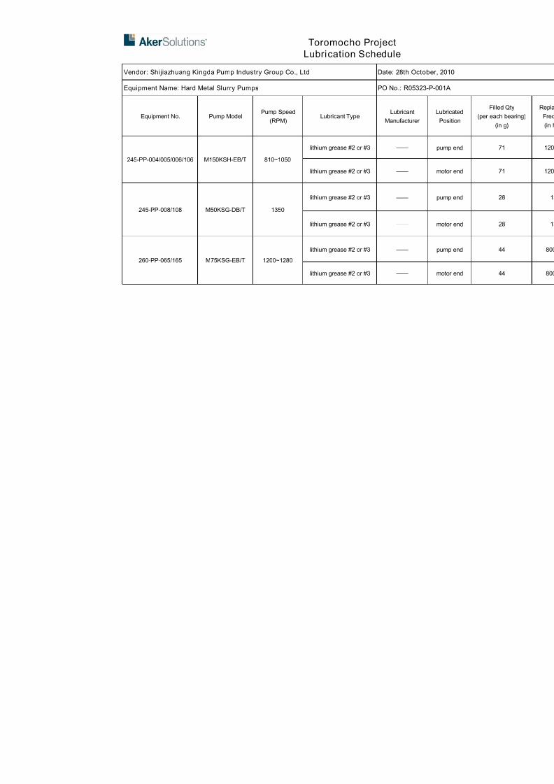
7/17/2019 R05323-P-001A-X009-0042.pdf
http://slidepdf.com/reader/full/r05323-p-001a-x009-0042pdf 460/463
Toromocho Project
Lubrication Schedule
Vendor: Shijiazhuang Kingda Pump Industry Group Co., Ltd Date: 28th October, 2010
Equipment Name: Hard Metal Slurry Pumps PO No.: R05323-P-001A
Equipment No. Pump ModelPump Speed
(RPM)Lubricant Type
Lubricant
Manufacturer
Lubrica
Positio
245-PP-004/005/006/106 M150KSH-EB/T 810~1050
lithium grease #2 or #3 —— pump e
lithium grease #2 or #3 —— motor e
245-PP-008/108 M50KSG-DB/T 1350
lithium grease #2 or #3 —— pump e
lithium grease #2 or #3 —— motor e
260-PP-065/165 M75KSG-EB/T 1200~1280
lithium grease #2 or #3 —— pump e
lithium grease #2 or #3 —— motor e

7/17/2019 R05323-P-001A-X009-0042.pdf
http://slidepdf.com/reader/full/r05323-p-001a-x009-0042pdf 461/463
Tormocho Project
LUBRICATION SCHEDULE
PO Number: R05323-P-001 Equipment: Standard End Suction Pumps
Vendor :SHIJIAZHUANG KINGDA PUMP Vendor contact Name : Wang zhao(Wendy)
page 1 of 1 E-mail :[email protected]
EQUIP NO. DESCRIPTION, WHERE USED LUBRICANT TYPE QUANTITY MANUFACTURERF
R
245-PP-004
245-PP-005
245-PP-006
245-PP-106
Front bearing NU322-C3POLYREX EM
(polyurea grease
60g
MOBIL
Rear bearing 6319-C3 45g
245-PP-008/108Front bearing NU319-C3 POLYREX EM
(polyurea grease
45gMOBIL
Rear bearing 6316-C3 34g
260-PP-065/165Front bearing NU319-C3 POLYREX EM
(polyurea grease
45gMOBIL
Rear bearing 6316-C3 34g

7/17/2019 R05323-P-001A-X009-0042.pdf
http://slidepdf.com/reader/full/r05323-p-001a-x009-0042pdf 462/463

7/17/2019 R05323-P-001A-X009-0042.pdf
http://slidepdf.com/reader/full/r05323-p-001a-x009-0042pdf 463/463


![*X009/301* - Mrs Smith' s Biology · [X009/301] Page two Read carefully 1 Check that the answer sheet provided is for Human Biology Higher (Section A). 2 For this section of the examination](https://img.pdfslide.us/doc/110x75/5e0fd1f3b2e8676ed651e512/x009301-mrs-smith-s-biology-x009301-page-two-read-carefully-1-check-that.jpg)


![#001a Prinsip Dasar Analisis [2007.05.Lastest]](https://img.pdfslide.us/doc/110x75/5695d4291a28ab9b02a081ef/001a-prinsip-dasar-analisis-200705lastest.jpg)