Embed Size (px)
Citation preview

R Y T E C
Spiral®
Owner’s Manual
Models
L & L/R (9-½” Side Column)
S & S/R (14” Side Column)
P.O. Box 403, One Cedar Parkway, Jackson, WI 53037 Phone 262-677-9046 Fax 262-677-2058
Rytec website: www.rytecdoors.com Rytec On-line store: www.rytecparts.com Rytec E-mail: [email protected], Parts E-mail: [email protected]
[Revision: AA (2017-04-19), R1071645-0, © Rytec Corporation 2009]

Spiral®
Door Series LIMITED WARRANTY
Rytec Corporation (“Seller”), an Illinois corporation with its principal place of business at One Cedar Parkway, PO Box 403,
Jackson, WI 53037, warrants to the original registered end-user commercial purchaser (“Buyer”) that the Spiral®
Door
Series (“Product”) sold to the Buyer will be free of defects in materials and workmanship (ordinary wear and tear excepted) for the time periods set forth below:
Mechanical components for a period of Five (5) Years from the date of shipment of the Product from the Seller’s plant (“Shipment”). Note: Motor assembly is a mechanical component.
Electrical components for a period of Two (2) Years from Shipment.
Standard door panel assemblies, including panel slats, hinge rollers, and hinges for a period of Two (2) Years from Shipment.
Drive pulleys, side column brush/vinyl seals, spring straps, lower tooth pulley assembly, drive & timing belts, energy chain and cable, wireless mobile unit battery, are considered wear items and are not covered under this Limited Warranty.
Aftermarket parts, accessories and assemblies for a period of ninety (90) days from the date of Shipment.
Remedies. Seller’s obligation under this Limited Warranty is limited to repairing or replacing, at Seller’s option, any part which is determined by Seller to be defective during the applicable warranty period. Such repair or replacement shall be the Seller’s sole obligation and the Buyer’s exclusive remedy under this Limited Warranty.
Labor. Except in the case of aftermarket parts, accessories and assemblies, labor is warranted for one year. This means that Seller will provide warranty service without charge for labor in the first year of the warranty period. Thereafter, a charge will apply in to any repair or replacement under this Limited Warranty. In the case of aftermarket parts, accessories and assemblies, Seller will provide replacement parts only.
Claims. Claims under this Limited Warranty must be made (i) within 30 (thirty) days after discovery and (ii) prior to expiration of the applicable warranty period. Claims shall be made in writing delivered to the Seller at the address provided in the first paragraph of this warranty. Buyer must allow Seller and Dealer, or their agents, a reasonable opportunity to inspect any Product claimed to be defective and shall, at Seller’s option, either (x) grant Seller and Dealer or their agents access to Buyer’s premises for the purpose of repairing or replacing the Product or (y) return of the Product to the Seller, f.o.b. Seller’s factory.
Original Buyer. This Limited Warranty is made to the original Buyer of the Product and is not assignable or transferable. This Limited Warranty shall not be altered or amended except in a written instrument signed by Buyer and Seller.
Not Warranted. Seller does not warrant against and is not responsible for, and no implied warranty shall be deemed to cover, damages that result directly or indirectly from: (i) the unauthorized modification or repair of the Product, (ii) damage due to misuse, neglect, accident, failure to provide necessary maintenance, or normal wear and tear of the Product, (iii) failure to follow Seller’s instructions for installation, operation or maintenance of the Product, (iv) use of the Product in a manner that is inconsistent with Seller’s guidelines or local building codes, (v) movement, settling, distortion, or collapse of the ground, or of improvements to which the Products are affixed, (vi) fire, flood, earthquake, elements of nature or acts of God, riots, civil disorder, war, or any other cause beyond the reasonable control of Seller, (vii) improper handling, storage, abuse, or neglect of the Product by Buyer or by any third party.
DISCLAIMERS. THIS WARRANTY IS EXCLUSIVE AND IN LIEU OF ALL OTHER REPRESENTATIONS AND WARRANTIES, EXPRESS OR IMPLIED, AND THE SELLER EXPRESSLY DISCLAIMS AND EXCLUDES ANY IMPLIED WARRANTIES OF MERCHANTABILITY OR FITNESS FOR PURPOSE. SELLER SHALL NOT BE SUBJECT TO ANY OTHER OBLIGATIONS OR LIABILITIES, WHETHER ARISING OUT OF BREACH OF CONTRACT, WARRANTY, TORT (INCLUDING NEGLIGENCE AND STRICT LIABILITY) OR OTHER THEORIES OF LAW, WITH RESPECT TO THE PRODUCTS SOLD OR SERVICES RENDERED BY THE SELLER, OR ANY UNDERTAKINGS, ACTS, OR OMISSIONS RELATING THERETO.
LIMITATION OF LIABILITY. IN NO EVENT WILL SELLER BE RESPONSIBLE FOR, OR LIABLE TO ANYONE FOR, SPECIAL, INDIRECT, COLLATERAL, PUNITIVE, INCIDENTAL, OR CONSEQUENTIAL DAMAGES, EVEN IF SELLER HAS BEEN ADVISED OF THE POSSIBILITY OF SUCH DAMAGES. Such excluded damages include, but are not limited to, personal injury, damage to property, loss of goodwill, loss of profits, loss of use, cost of cover with any substitute product, interruption of business, or other similar indirect financial loss.
Product Descriptions. Any description of the Products, whether in writing or made orally by the Seller or the Seller’s agents, including specifications, samples, models, bulletins, drawings, diagrams, engineering or similar materials used in connection with the Buyer’s order, are for the sole purpose of identifying the Product and shall not be construed as an express warranty. Any suggestions by the Seller or the Seller’s agents regarding the use, application, or suitability of the Product shall not be construed as an express warranty unless confirmed to be such in writing by the Seller.
Limited Warranty Void. This Limited Warranty shall be void in its entirety if: (a) The Product is modified in a manner not approved in writing by Seller; or (b) Buyer fails to maintain the Product in accordance with instructions contained in the Owner’s Manual for the Product.
*Spiral Door Series Limited Warranty excludes Spiral VP door model.
© Rytec Corporation 06.02.2016


TABLE OF CONTENTS PAGE
INTRODUCTION ........................................................................................................... 1
HOW TO USE MANUAL ...................................................................................................... 1
DOOR SERIAL NUMBER(S) ............................................................................................... 1
GENERAL ARRANGEMENT OF DOOR COMPONENTS ................................................... 1
OPERATION ................................................................................................................. 2
OPERATING CONTROL SYSTEM ...................................................................................... 2
MODES OF OPERATION .................................................................................................... 2
Automatic Mode of Operation ........................................................................................ 2
Manual Mode of Operation ............................................................................................. 2
OPEN AND CLOSE DOOR LIMIT POSITIONS ................................................................... 3
Close Limit Position........................................................................................................ 3
Open Limit Position ........................................................................................................ 3
GENERAL ............................................................................................................................ 3
PHOTO EYES ...................................................................................................................... 3
System Reset — Photo Eyes .......................................................................................... 4
DOOR PANEL REVERSING EDGE ..................................................................................... 4
System Reset — Door Panel Reversing Edge ............................................................... 4
POWER DRIVE SYSTEM .................................................................................................... 4
DOOR LIFT SYSTEM........................................................................................................... 5
Secondary Drive Belts .................................................................................................... 5
Springs & Spring Packs ................................................................................................. 5
SAMPLE OBJECT LIST ...................................................................................................... 7
GENERAL CLEANING ................................................................................................. 8
PLANNED MAINTENANCE ......................................................................................... 8
RECOMMENDED INSPECTION SCHEDULE ...................................................................... 8
DAILY INSPECTION ............................................................................................................ 8
Visual Damage Inspection .............................................................................................. 8
Door Operation Inspection ............................................................................................. 9
Bottom Bar Reversing Edge Inspection ........................................................................ 9
Photo Eye Inspection .................................................................................................... 10
Cleaning Photo Eyes .................................................................................................... 11
Cleaning Vision Panels ................................................................................................. 11
QUARTERLY INSPECTION .............................................................................................. 11
TABLE OF CONTENTS PAGE
Electrical/Control Panel Inspection ............................................................................. 11
Electrical/Door Head Junction Box Inspection ........................................................... 12
Hardware Inspection ..................................................................................................... 13
Side Column/Mounting Anchor Inspection ................................................................. 13
Head Assembly Inspection........................................................................................... 14
Primary Drive Belt Inspection ...................................................................................... 15
Secondary Drive Belt Inspection ................................................................................. 16
Spreader Bar Inspection ............................................................................................... 16
Weather Seal Inspection ............................................................................................... 17
Spring Pack Inspection ................................................................................................ 17
Spring Strap Inspection ................................................................................................ 18
Wireless Antenna Inspection ....................................................................................... 18
Door Panel Inspection .................................................................................................. 18
Bottom Bar Reversing Edge Inspection ...................................................................... 20
Door Limit Inspection ................................................................................................... 21
Motor Brake & Release Cable Inspection .................................................................... 21
ADJUSTMENTS ......................................................................................................... 21
PRIMARY DRIVE BELT ..................................................................................................... 21
SECONDARY DRIVE BELT............................................................................................... 23
DOOR PANEL ................................................................................................................... 24
PHOTO EYE ALIGNMENT ................................................................................................ 25
BRAKE RELEASE CABLE ADJUSTMENT ....................................................................... 25
REPLACEMENT PROCEDURES ............................................................................... 25
PRIMARY DRIVE BELT ..................................................................................................... 25
SECONDARY DRIVE BELT............................................................................................... 26
MOTOR BRAKE RELEASE CABLE .................................................................................. 28
DOOR PANEL ................................................................................................................... 30
WEATHER SEAL REPLACEMENT ................................................................................... 31
SPRING STRAP REPLACEMENT ..................................................................................... 32
SPRING PACK REPLACEMENT ....................................................................................... 34
DOOR ROLLER REPLACEMENT ..................................................................................... 35
PHOTO EYE REPLACEMENT ........................................................................................... 37
Cleaning Photo Eyes .................................................................................................... 37

TABLE OF CONTENTS PAGE
REVERSING EDGE REPLACEMENT ............................................................................... 37
WIRELESS ANTENNA BRACKET/ENCODER.................................................................. 39
VISION PANEL MAINTENANCE ....................................................................................... 41
Vision Panel (Slat) Cleaning ......................................................................................... 41
Cleaning Agents Found To Be Compatible w/ Lexan™ Sheets: ................................ 41
Vision Panel (Slat) Cleaning ......................................................................................... 42
PARTS LIST ............................................................................................................... 43
PARTS ORDERING INFORMATION ................................................................................. 43
How to Order Parts ....................................................................................................... 43
Substitute Parts ............................................................................................................ 43
Return of Parts .............................................................................................................. 43
RYTEC TECHNCIAL KNOWLEDGE CENTER .................................................................. 43
SPIRAL DOOR ASSEMBLY-LAYOUT .............................................................................. 45
SPIRAL LH DOOR ASSEMBLY-LAYOUT ......................................................................... 46
DOOR ASSEMBLY-LAYOUT BOM ................................................................................... 47
SIDE COLUMN ASSEMBLY .............................................................................................. 48
SIDE COLUMN ASSEMBLY BOM..................................................................................... 49
FRONT & REAR MOUNTED PHOTO EYES & PHOTO EYE CABLES ............................. 49
FRONT & REAR MOUNTED PHOTO EYES & PHOTO EYE CABLES BOM .................... 51
STRAPS & BELTS (STT-L & S) ........................................................................................ 52
STRAPS & BELTS (STT-L & S) BOM ............................................................................... 52
........................................................................................................................................... 52
PULLEYS, SPIRAL (STT-L & S, SST-L & S) ..................................................................... 53
PULLEYS, SPIRAL (STT-L & S, SST-L/R & S/R) BOM .................................................... 53
SINGLE SPRING PACK (STT-L & S, SST-L & S) ASSEMBLY ......................................... 53
SINGLE SPRING PACK (STT-L & S, SST-L & S) ASSEMBLY BOM ............................... 55
DOUBLE SPRING PACK (STT-L & S, SST-L & S) ASSEMBLY ....................................... 56
DOUBLE SPRING PACK (STT-L & S, SST-L & S) ASSEMBLY BOM .............................. 57
TRIPLE SPRING PACK (STT-L & S, SST-L & S) ASSEMBLY ......................................... 58
TRIPLE SPRING PACK (STT-L & S, SST-L & S) ASSEMBLY BOM ................................ 59
HEAD ASSEMBLY STT-L & SST-L ................................................................................... 60
HEAD ASSEMBLY STT-L & SST-L BOM .......................................................................... 62

TABLE OF CONTENTS PAGE
HEAD ASSEMBLY STT-S & SST-S .................................................................................. 64
HEAD ASSEMBLY STT-S & SST-S BOM ......................................................................... 67
BRAKE RELEASE ASSEMBLY ........................................................................................ 68
BRAKE RELEASE ASSEMBLY BOM ............................................................................... 69
WIRELESS ANTENNA BRACKET & ENCODER ASSEMBLY ......................................... 70
WIRELESS ANTENNA BRACKET & ENCODER ASSEMBLY BOM ................................ 71
SPREADER AND DOOR PANEL ASSEMBLY .................................................................. 72
SPREADER AND DOOR PANEL ASSEMBLY BOM ........................................................ 73
DOOR PANEL BOTTOM BAR END BRACKET ASSEMBLIES ........................................ 73
DOOR PANEL BOTTOM BAR END BRACKET ASSEMBLY BOMS ................................ 75
REVERSING EDGE – WIRELESS ..................................................................................... 76
REVERSING EDGE – WIRELESS BOM ............................................................................ 77
SPIRAL PANEL LIFTING BRACKET ................................................................................ 78
SPIRAL PANEL LIFTING BRACKET BOM ....................................................................... 79

INTRODUCTION-HOW TO USE MANUAL
1
INTRODUCTION
The information contained in this manual will allow
you to operate and maintain your Rytec® Spiral
®
Door in a manner which will ensure maximum life
and trouble-free operation.
Any unauthorized changes in procedure, or failure to
follow the steps as outlined in this manual, will
automatically void the warranty. Any changes in the
working parts, assemblies, or specifications as
written that are not authorized by Rytec Corporation
will also cancel the warranty. The responsibility for
the successful operation and performance of this
door lies with the owner of the door.
DO NOT OPERATE OR PERFORM MAINTENANCE
ON THIS DOOR UNTIL YOU READ AND
UNDERSTAND THE INSTRUCTIONS CONTAINED
IN THIS MANUAL.
If you have any questions contact your Rytec
representative or call the Rytec Technical Support
Department at 800-628-1909. Always refer to the
serial number of the door when calling the
representative or Technical Support.
The wiring connections and schematics in this
manual are for general information purposes only. A
wiring schematic is provided with each individual
door specifically covering the control panel and
electrical components of that door. The schematic for
a specific door is shipped inside the cover of the
System 4 control panel.
HOW TO USE MANUAL
Throughout this manual, the following key words are
used to alert the reader of potentially hazardous
situations, or situations where additional information
to successfully perform the procedure is presented:
WARNING is used to indicate the potential
for personal injury, if the procedure is not
performed as described.
CAUTION is used to indicate the potential for
damage to the product or property damage,
if the procedure is not followed as
described.
IMPORTANT: IMPORTANT is used to relay
information CRITICAL to the
successful completion of the
procedure.
NOTE: NOTE is used to provide additional
information to aid in the performance of
the procedure or operation of the door, but
not necessarily safety related.
DOOR SERIAL NUMBER(S)
To obtain your DOOR SERIAL NUMBER, there are
three (3) universal locations that this information can
be attained. These are on the left side column
assembly (at approximately eye level), on the non-
drive side head console assembly, and inside the
door of the System 4 Control panel. (See Figure 1)
When installing multiple doors of the same
model, verify & match the serial numbers of
all the components for each door (i.e. control
panel, side columns, drive assembly, etc.).
Mark any items not previously marked.
NOTE: The following illustration shows the front
side of the door. Left and right sides are
determined when viewing the front side of
the door.
Figure 1
GENERAL ARRANGEMENT OF DOOR COMPONENTS
Figure 2 shows the location of the major components
of your Spiral door. This illustration also shows the
general placement of the associated control sub-
assemblies for a typical installation.
Motor-Gear Drive
Fused Disconnect (By Others)
System 4 Control Panel
Side Columns
Door Assembly
OPERATION-OPERATING CONTROL SYSTEM
2
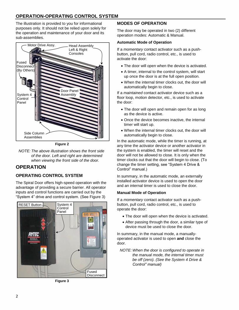
The illustration is provided to you for informational
purposes only. It should not be relied upon solely for
the operation and maintenance of your door and its
sub-assemblies.
Figure 2
NOTE: The above illustration shows the front side
of the door. Left and right are determined
when viewing the front side of the door.
OPERATION
OPERATING CONTROL SYSTEM
The Spiral Door offers high-speed operation with the
advantage of providing a secure barrier. All operator
inputs and control functions are carried out by the
“System 4” drive and control system. (See Figure 3)
Figure 3
MODES OF OPERATION
The door may be operated in two (2) different
operation modes: Automatic & Manual.
Automatic Mode of Operation
If a momentary contact activator such as a push-
button, pull cord, radio control, etc., is used to
activate the door:
The door will open when the device is activated.
A timer, internal to the control system, will start
up once the door is at the full open position.
When the internal timer clocks out, the door will
automatically begin to close.
If a maintained contact activator device such as a
floor loop, motion detector, etc., is used to activate
the door:
The door will open and remain open for as long
as the device is active.
Once the device becomes inactive, the internal
timer will start up.
When the internal timer clocks out, the door will
automatically begin to close.
In the automatic mode, while the timer is running, at
any time the activator device or another activator in
the system is enabled, the timer will reset and the
door will not be allowed to close. It is only when the
timer clocks out that the door will begin to close. (To
change the timer setting, see “System 4 Drive &
Control” manual.)
In summary, in the automatic mode, an externally
installed activator device is used to open the door
and an internal timer is used to close the door.
Manual Mode of Operation
If a momentary contact activator such as a push-
button, pull cord, radio control, etc., is used to
operate the door:
The door will open when the device is activated.
After passing through the door, a similar type of
device must be used to close the door.
In summary, in the manual mode, a manually-
operated activator is used to open and close the
door.
NOTE: When the door is configured to operate in
the manual mode, the internal timer must
be off (zero). (See the System 4 Drive &
Control” manual)
Head Assembly Left & Right Consoles
Fused Disconnect (By Others)
System 4 Control Panel
Side Column Assemblies
Door Panel Assembly
Motor Drive Assy.
System 4 Control Panel
Fused Disconnect
RESET Button

OPERATION-OPEN AND CLOSE DOOR LIMIT POSITIONS
3
OPEN AND CLOSE DOOR LIMIT POSITIONS
See the Rytec System 4 Drive & Control Manual for
the proper procedure for setting the open and close
door limits. The open and close door limit positions
are detailed below.
Close Limit Position
The “close” limit position should be adjusted so that
the door travel allows the rubber bottom edge, which
is located at the door panel bottom, to gently seal
against the floor. (See Figure 4)
Premature wear or damage to the reversing
edge or other bottom bar parts can occur if
the door seal is allowed to seal too tightly
against the floor.
Figure 4
Open Limit Position
The “open” limit position should be adjusted so that
the door travel allows the bottom bar assembly to
stop at the position as shown in Figure 5.
Figure 5
GENERAL
For more operating instructions, including Control
Panel System Inputs, Modes of Operation,
Accessing Parameters and Miscellaneous Inputs,
see the “System 4 Drive & Control” manual.
PHOTO EYES
Your Rytec Spiral Door is equipped with two (2) sets
of photo eyes that monitor the opening of the door.
The purpose of these photo eyes is to hold the door
open or, if the door is closing, reverse the direction of
the door if a person or object crosses the path of the
photo eye beam. After the obstruction breaking the
photo eye beam is removed:
If the door was originally opened by an automatic
activator, the door will close automatically.
If the door was originally opened by a non-
automatic activator, the door will remain open
until it is closed by the manual/non-automatic
activator.
Two (2) side column factory mounted photo eye sets
are included with the Spiral Door as a standard. The
photo eyes serve as a safety device. They prevent
the door from closing if an object is in the path of
either photo eye set light beam. The photo eyes are
not meant to be used as activators to open or close
the door.
Each set of photo eyes consist of an emitter module
& a receiver module. The factory installed photo eyes
are mounted in the side columns. (See Figure 6)
Figure 6
Only the rubber flap of the bottom edge should be touching the floor. DO NOT drive bottom edge into the floor.
Rubber Reversing Edge
Rubber Reversing Edge
Top of Side Column
A9500232
Factory-Installed
Photo Eyes (Located
in Door Side Columns)
A9600041
Rear Door Seal removed to
show Rear Side Column
Mounted Photo Eye
Left Hand Side Column Shown
Photo Eye Cables
Side Column
Cover not shown
OPERATION-DOOR PANEL REVERSING EDGE
4
System Reset — Photo Eyes
If either set of photo eyes detects an object has
entered the door opening while the door is closing,
the door will immediately reverse direction and move
to the fully open position. The door will remain
parked in this position until the object has been
removed from within the opening. If the front set of
photo eyes detects the interruption, the display will
read “Photoeye – Fr”. If the rear set of photo eyes
detects the interruption, the display will read
“Photoeye -Rr”.
The door will remain parked in the fully open position
for as long as the object(s) is in the path of the door
opening. Once the object causing the photo eyes to
trip is removed from the door opening:
If the auto-close timer is off, the door close (▼)
button must be pressed to close the door.
If the auto-close timer is on, the door will close
when the timer clocks out.
After the door is closed, the display will read “Spiral
Door” and the control system will wait for operator
input.
DOOR PANEL REVERSING EDGE
An electrically operated reversing edge is mounted
along the bottom of the door panel. It is designed to
provide a seal between the door panel and the floor.
If this pressure- sensitive edge comes in contact with
an object as the door is closing, the control system
will reverse the door and move it to the fully open
position. Once the door reaches the fully opened
position:
If the auto-close timer was on when the door was
opened, the door will begin to close after the timer
clocks out.
If the auto-close timer is off, the door close (▼)
button must be pressed to close the door.
If the reversing edge is activated 3 consecutive
times the door will open & remain open displaying
F:361 “Edge Tripped” (See Figure 7)
NOTE: Anytime the reversing edge is activated,
the “System 4” Control Panel will read
“F.361” (Edge Tripped). After the object in
the door opening is removed, the control
panel will require a manual reset before
the door will operate again. To reset the
control system, press and hold the RESET
(●) button for approximately three (3)
seconds.
Figure 7
System Reset — Door Panel Reversing Edge
Anytime the door is closing and the reversing edge
along the bottom bar makes contact with an object,
the display will read “F.361” (Edge Tripped) and the
door will move to the fully open position. If the
reversing edge is activated 3 consecutive times the
door will open and remain open displaying “F:361”
“Edge Tripped”.
1. To reset the control system with “F.361”
displayed, first make sure the area directly below
the path of the door is clear of all objects and
personnel.
2. Then press and hold the RESET (●) button on the
control panel to reset the control system. (See
Figure 3)
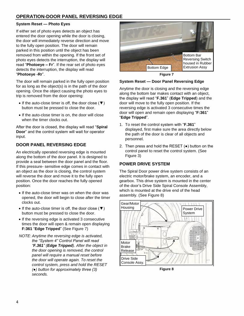
POWER DRIVE SYSTEM
The Spiral Door power drive system consists of an
electric motor/brake system, an encoder, and a
gearbox. This drive system is mounted in the center
of the door’s Drive Side Spiral Console Assembly,
which is mounted at the drive end of the head
assembly. (See Figure 8)
Figure 8
Gear/Motor Housing
Drive Side Console Assy.
Power Drive System
Bottom Edge
Bottom Bar Reversing Switch housed in Rubber Extrusion Assy
Motor Brake Release

OPERATION-DOOR LIFT SYSTEM
5
The power drive incorporates an electric brake used
as a parking brake to prevent door movement when
electrical power to the door is shut off. A manual
brake release is provided for manual opening or
closing of the door should there be a power failure, or
when routine maintenance needs to be performed
with the power disconnected.
An encoder, mounted to the end of the motor
gearbox, generates electrical signals & magnetic
pulses as the door panel is moved. These signals are
used by the control system to monitor & track the
position of the door. Once the door and control
system are synchronized, they will remain
synchronized.
The drive motor is connected to the drive shaft pulley
by way of the primary drive belt. The tension of the
drive belt is controlled by positioning the drive motor
on its mounting bracket. (See Figure 9)
Figure 9
DOOR LIFT SYSTEM
Secondary Drive Belts
Near each end of the drive shaft is a secondary drive
pulley. Installed on each pulley is a secondary drive
belt. Each drive belt runs down through its adjoining
side column, to a small guide pulley mounted in the
base of each column. (See Figure 10)
Figure 10
End brackets in the bottom corners of the door
connect the door to the secondary drive belts. A
clamp on the end of each bracket locks the belt to
the door. Depending on the direction the drive
system turns the drive shaft, the secondary drive
belts will rotate up or down to lift or lower the door.
(See Figure 11)
Figure 11
Springs & Spring Packs
The springs assist the power drive system with lifting
the door. Depending on the size of your door, up to
12 springs can be used.
Springs are arranged in spring pack assemblies
consisting of one, two, or three springs. Spring packs
are evenly distributed between the right and left side
columns and are listed in the Object List (See Figure
13). A maximum of six springs can be installed in
each side column. (See Figure 12)
Belt Guide Pulley Assy
Side Column Assembly
Secondary Drive Belt
End Bracket
Right Hand Side Column Front Shown
Side Column Base Plate
Left Hand Drive Side Column Front Shown
Secondary Drive Belt
Belt Guide Pulley Assy
M8 x 40 Post
M8 Nuts: Pulley Tension controlled by upper nut on front post
Belt Guide Pulley Assy Adjusting Tabs
MORE TENSION
(4) Bolts to loosen for motor adjustment.
LESS TENSION
Primary Drive Belt should
deflect approximately 1/8”
Tensioner Bolt to adjust motor & belt tension.
Head Console Frame Shown Transparent for Clarity
A9500029
OPERATION-DOOR LIFT SYSTEM
6
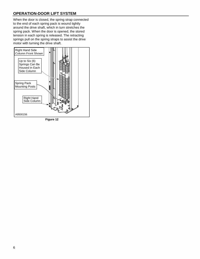
When the door is closed, the spring strap connected
to the end of each spring pack is wound tightly
around the drive shaft, which in turn stretches the
spring pack. When the door is opened, the stored
tension in each spring is released. The retracting
springs pull on the spring straps to assist the drive
motor with turning the drive shaft.
Figure 12
Up to Six (6) Springs Can Be Housed in Each Side Column
Right Hand Side Column
Right Hand Side Column Front Shown
Spring Pack Mounting Posts
A9500156
-SAMPLE OBJECT LIST
7
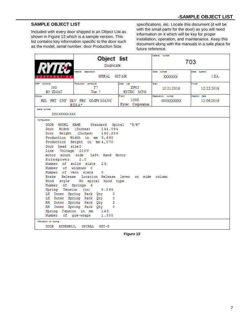
SAMPLE OBJECT LIST
Included with every door shipped is an Object List as
shown in Figure 13 which is a sample version. This
list contains key information specific to the door such
as the model, serial number, door Production Size
specifications, etc. Locate this document (it will be
with the small parts for the door) as you will need
information on it which will be key for proper
installation, operation, and maintenance. Keep this
document along with the manuals in a safe place for
future reference.
Figure 13

GENERAL CLEANING-RECOMMENDED INSPECTION SCHEDULE
8
GENERAL CLEANING
Household cleaners are sufficient for general
cleaning of the door panel. Isopropyl alcohol can be
used on more difficult areas but avoid using bleach
and industrial grade cleaners or solvents. Contact the
RYTEC Technical support if you have any questions.
PLANNED MAINTENANCE
RECOMMENDED INSPECTION SCHEDULE
Action Items Daily Quarterly
Visual Damage Inspection
Door Operation Inspection
Bottom Bar Reversing Edge Inspection
Photo Eye Inspection
Cleaning Vision Panels
Electrical/Control Panel Inspection
Electrical/Door Head Junction Box Connection Inspection
Hardware Inspection
Side Column/Mounting Anchor Inspection
Head Assembly Inspection
Primary Drive Belt Inspection
Secondary Drive Belt Inspection
Spreader Bar Inspection
Weather Seal Inspection
Spring Pack Inspection
Spring Strap Inspection
Wireless Antenna Inspection
Door Panel Inspection
Bottom Bar Reversing Edge Inspection
Door Limit Inspection
Motor Brake & Release Cable Inspection
IMPORTANT: This door is designed such that it
does not require lubrication.
DO NOT lubricate any parts,
components, or assemblies of this
door. This includes the door panel
rollers, guides, & track. Lubricants
will attract dust & dirt, which can
cause the door panel to bind.
Also, the gearbox used with this
Spiral Door is a sealed unit — it
does not require any lubrication.
DAILY INSPECTION
Visual Damage Inspection
Visually inspect the door for damaged components
such as dented door panel(s), dented side column(s),
torn or damaged reversing edge, damaged or broken
photo eyes, etc. (See Figure 14)
Figure 14
Head & Upper Track Assembly: Inspect for dents
or damage that may prevent the door from opening
or closing properly.
Door Panel Assembly: Inspect for dents, holes, and
worn areas. If equipped with windows, inspect them
for damage or dirt that may impair vision — clean or
replace as required.
Bottom Bar Reversing Edge: Inspect the bottom
bar for damaged, missing, or loose hardware. Inspect
the bottom edge seal along the lower edge of the
bottom bar for tears and/or holes. Inspect the edge
itself.
Side Columns and Covers: Inspect for damage that
may prevent the door from operating properly.
Wiring, Cords, Springs, Straps, & Drive Belts:
Inspect for damage & wear that may prevent the door
from operating properly.
Photo Eyes: Inspect the lens of each photo eye for
damage or dirt that may prevent the photo eyes from
working properly. Clean or replace as required.
Reversing Edge: Inspect the entire length of the
reversing edge for damage such as tears and holes,
and for missing or loose hardware. Inspect the edge
itself.
Motor-Gear Drive
System 4 Control Panel
Door Panel Assembly Note: Individual slats can be ordered. See parts section.
Non-Drive Console
Side Column Assemblies
Fused Disconnect (By Others)
Brake Release Lever
Drive Side Console

PLANNED MAINTENANCE-DAILY INSPECTION
9
Door Operation Inspection
Run the door through four or five complete cycles to
make sure it is operating smoothly & efficiently. Also
make sure there is no binding or unusual noise(s).
DO NOT continue to operate the door if it is not
working properly as this could further complicate the
problem.
Bottom Bar Reversing Edge Inspection
DO NOT stand under the door when
performing the following test. If the
reversing edge sensor is not working
properly, the door could strike the person
performing the procedure. DO NOT use the
door if the sensor is not working properly.
1. Move the door to the fully open position by
pressing the door open (▲) button located on the
control panel.
2. Press the door close (▼) button.
3. While the door is closing, hit the rubber reversing
edge that runs along the bottom edge of the door.
Stand outside the photo eyes to avoid activating
the photo eye circuit. (See Figure 15)
Inspect the bottom seal along the bottom bar
assembly for wear, tears, and/or abrasion. Replace
any worn or damaged parts as required. (See Figure
15)
Figure 15
If the reversing edge sensor is working correctly, the
door will reverse direction and move to the fully open
position, if the door was opened using a timer input,
the door will begin counting that timer. When the
door timer reaches 0 the door will again begin to
close. If the reversing edge is activated 3
consecutive times the door will open and remain
open displaying F:361 “Edge Tripped”.
To reset the control system, see “System Reset –
Door Reversing Edge” on page 4.
If the reversing edge sensor is not working properly,
the control system will only allow the door to open
and the control panel will display an associated error
code.
NOTE: A normal resistance measurement across
the reversing edge sensor will read
approximately 8.2 k-ohms. With the rubber
edge compressed, the resistance will drop
to about zero ohms.
4. Check the wires from the reversing edge cable
that go to the terminal block of the mobile unit.
Make sure that they are tightly secure. Inspect
terminal block and cable for damage and replace
any missing or damaged hardware. (See Figure
16)
Figure 16
5. Inspect the rubber reversing edge. It should
be in good condition with no visible holes,
cracks, or tears. Replace the rubber
reversing edge if necessary. To replace the
reversing edge, see “REVERSING EDGE
REPLACEMENT” on page 37.

PLANNED MAINTENANCE-DAILY INSPECTION
10
Photo Eye Inspection
To prevent the front & rear sets of eyes from
interfering with each other, the emitter and receiver
modules of each set are mounted diagonally across
from each other. The side column mounted photo
eye emitters are mounted in the left-front and right-
rear corners of the door. The side column mounted
photo eye receiver modules are located in the right-
front and left-rear corners.
When the door is open and an object breaks either
beam of light, the door will remain open until the
beam is restored (object removed). If the door is
closing at the time either beam is broken, the door
will immediately reverse direction and move back to
the fully open position, where it will remain parked
until the beam of light is restored (object removed).
It is important to note that the sets of photo eyes are
interchangeable. Each set performs the same
function and operates with the same set of photo eye
modules. Also, the photo eye modules that make up
the sets of photo eyes each have one indicator light.
Inspect the lens of each photo eye for damage or
dirt that may prevent the photo eyes from working
properly — clean or replace as required.
NOTE: Photo eyes act as a safety device to pre-
vent the door from closing if an object or
person is within the photo eye beam. The
photo eyes are not to be used as door
activators.
Figure 17
FRONT & REAR SIDE COLUMN FACTORY
MOUNTED PHOTO EYES
The eyes are receiving power & are aligned when the
indicator on the emitter module (left-front and right-
rear corners of the door) is green and the indicator
on the receiver module (right-front and left-rear
corners of the door) emit a yellow light which only
illuminates when it is in proper alignment with the
transmitter. If the receiver module indicator light is
out, the eyes are not aligned. The emitter has a
single green light that comes on when it is powered
up. (See Figure 17)
1. The front & rear photo eyes are internally
mounted on the rear of the side column. Check
that the photo eye & all connections are secure &
there is nothing damaged.
2. Confirm the cable/wires are securely & safely
routed as necessary through the side column,
across the rear spreader, through the consoles, to
the junction box, to the control panel, and
correctly wired as required.
PHOTO EYE SYSTEM TESTING
NOTE: Avoid interrupting both beams of light
when testing one, or the other, set of
photo eyes. Interrupt only one beam of
light at a time.
To prevent injury to personnel and damage
to equipment, the photo eye circuit must be
thoroughly tested to make sure the photo
eye system is operating correctly.
Test the door photo eyes by doing the following
procedure:
1. Move the door to the fully open position by
pressing the door open (▲) button located on the
control panel.
2. Wait for the door to begin to close or press the
door close (▼) button.
3. While the door is closing place an object between
the set of photo eyes to be tested, interrupting the
beam of light between them.
NOTE: When the front beam of light is interrupted,
the display on the control panel will read
“Photo Eye – Fr”. When the rear beam of
light is interrupted, the display will read
“Photo Eye – Rr”.
Factory-Installed Eyes
(Located in Door Side
Columns
A9600041
Rear Door
Seal removed
to show Rear
Side Column
Mounted
Photo Eye
Left Hand Side Column “L” Series Shown
Photo Eye Cables

PLANNED MAINTENANCE-QUARTERLY INSPECTION
11
4. When operating properly the moment the beam of
light is interrupted, the control panel should
reverse the direction of the door and park it in the
fully-open position. When the beam of light is
restored, the door should be able to move to the
closed position.
If the photo eyes do not operate properly, the lens
may be dirty. Clean as required using window
cleaner and a clean, soft cloth (See “Cleaning
Photo Eyes” section on page 11). Check that
each photo eye set is properly lit up & aligned.
Retest the set of eyes. If cleaning does not
resolve the problem, realign or replace the photo
eyes as required.
To align the photo eyes, see “PHOTO EYE
ADJUSTMENT” on page 25 for adjustment
procedures. To replace the eyes, see “PHOTO
EYE REPLACEMENT” on page 37.
5. Repeat this procedure for each set of photo eyes
only after verifying that the set of eyes just tested
are working properly.
Cleaning Photo Eyes
The disconnect must be in the OFF position
and properly locked and tagged before
performing the following procedures.
A dirty photo eye lens can cause a photo eye module
to fail or operate intermittently. After any work is
performed on either set of photo eyes, it is
recommended that the lens on each photo eye be
cleaned using a clean, soft cloth and household
window cleaner.
Cleaning Vision Panels
The Vision Panels should be inspected on a daily
basis for dirt, grease, etc. & any abrasions. Cleaning
must be done when dirt, grease, abrasions, or
anything else that diminishes panel clarity is
observed. Also refer to “VISION PANEL
MAINTENANCE” section on page 41 for additional
information. Follow the procedure(s) as necessary:
The disconnect must be in the OFF position
and properly locked and tagged before
performing the following procedures.
1. Remove power to the control panel by placing the
fused disconnect in the OFF position.
ROUTINE CLEANING
1. Rinse with flowing water.
2. Clean with warm water and small amount of mild
non-abrasive soap (dish soap).
3. Lightly rinse vision panels using a water spray.
4. Remove excess water using a clean and dry
microfiber of lint free cloth.
5. Use a small squeegee to completely dry all
panels.
6. Wipe any additional moisture with dry microfiber
or lint free cloth.
OCCASIONAL HEAVY CLEANING & FINE
SCRATCH REMOVAL
1. Remove all surface dirt and dust with warm water
spray.
2. Mix a mild non-abrasive soap (dish soap) into a
bucket of warm water.
3. Gently wash using a microfiber or lint free cloth
keeping the cloth sudsy at all times.
4. Lightly rinse vision panels using a water spray.
5. Remove excess water using a clean and dry
microfiber or lint free cloth.
6. Use a small squeegee to completely dry all vision
panels.
7. Wipe any additional moisture with a dry microfiber
or lint free cloth.
8. Over the counter products can be used to polish
the vision panels. Products such as (Novus Polish
#2 – www.novuspolish.com) is designed
specifically for polycarbonate windows and will
help maintain clarity and shine of the vision
panels. Follow the instructions on the product for
the proper application.
NOTE: The product must be non-abrasive and
designed specifically for polycarbonate
windows.
QUARTERLY INSPECTION
Electrical/Control Panel Inspection
1. Remove power to the control panel by placing the
fused disconnect in the OFF position.
The disconnect must be in the OFF position
and properly locked and tagged before
performing the following procedures.

PLANNED MAINTENANCE-QUARTERLY INSPECTION
12
2. Open the door to the control panel. (See Figure
18)
3. Inspect all electrical lines leading to the control
panel. Check all electrical connections inside the
control panel. All connections must be tightly
secured.
Figure 18
4. Check for pinched, cracked, or damaged wires &
insulation. Repair or replace wires as needed. For
the proper control panel electrical connection
inspection procedure, see the Rytec “System 4
Drive & Control” manual.
5. Inspect the serial number decal for legibility and
adhesion. (See Figure 19)
Figure 19
Electrical/Door Head Junction Box Inspection
DOOR HEAD JUNCTION BOX
1. Move the door to the fully closed position by
pressing the door close (▼) button located on the
control panel.
2. Turn off the door power by placing the fused
disconnect in the OFF position.
The disconnect must be in the OFF position
and properly locked and tagged before
performing the following procedures.
3. Remove the cover from the door head junction
box located above the drive motor assembly as
shown. (See Figure 20)
Figure 20
4. Inspect all electrical connections in the door head
junction box. All connections must be tightly
secured.
Left Hand Drive Side Console Shown
Cable Cord Grip for Photo Eye Cables
Single Cable Cord Grip
A9500151 Door Head Junction Box

PLANNED MAINTENANCE-QUARTERLY INSPECTION
13
5. Check for pinched, cracked, or damaged wires &
insulation. Repair or replace wires as needed. For
the proper control panel electrical connection
inspection procedure, see the Rytec “System 4
Drive & Control” manual.
6. Replace the cover.
UPPER JUNCTION BOX
NOTE: The upper junction box is an optional item
that may have been installed during the
installation of your door. If an upper
junction box was installed, it was most
likely mounted on the wall, just above the
control panel. If your door has an upper
junction box, it must be inspected.
1. Turn off the door power by placing the fused
disconnect in the OFF position.
The disconnect must be in the OFF position
and properly locked and tagged before
performing the following procedures.
2. Remove the cover from the upper junction box
located near the left side column. (See Figure 21)
Figure 21
3. Inspect all electrical connections in the upper
junction box. All connections must be tightly
secured.
4. Check for pinched, cracked, or damaged wires &
insulation. Repair or replace wires as needed. For
the proper control panel electrical connection
inspection procedure, see the Rytec “System 4
Drive & Control” manual.
5. Replace the cover.
Hardware Inspection
Make sure all nuts, bolts, set screws, and anchors
are tight throughout the door. Example: motor
mounting bolts, wall mounting hardware, floor
anchors, shaft set screws, track mounting fasteners,
etc.
NOTE: To access the floor and wall anchors, you
must first remove the cover from each side
column.
Side Column/Mounting Anchor Inspection
1. Move the door to the fully opened position by
pressing the door open (▲) button located on the
control panel.
2. Remove power to the control panel by placing the
fused disconnect in the OFF position.
The disconnect must be in the OFF position
and properly locked and tagged before
performing the following procedures.
3. Remove the side cover from each side column.
Each cover is held in place with 20-mm long
Button Head TORX® screws.
4. Inspect all nuts, through bolts, threaded rods, and
anchors used to secure the side columns to the
wall and floor. Tighten any loose hardware.
Replace any missing or damaged hardware as
required. (See Figure 22 & Figure 23)
Figure 22
Upper J-Box Assembly by others
Left Hand Drive Side Console Shown

PLANNED MAINTENANCE-QUARTERLY INSPECTION
14
Figure 23
5. Inspect the hardware used to attach the vertical
track sections to the left and right side columns.
Tighten the hardware as required. Replace any
missing or damaged hardware. (See Figure 22)
Figure 24
Head Assembly Inspection
1. Move the door to the fully closed position by
pressing the door close (▼) button located on the
control panel.
2. Remove power to the control panel by placing the
fused disconnect in the OFF position.
The disconnect must be in the OFF position
and properly locked and tagged before
performing the following procedures.
3. Remove the end covers from both the head
console assemblies & the belt cover from the
drive side console. Each is held in place by
Button Head TORX® screws. (See Figure 25)
Figure 25
4. Inspect the hex head screws used to secure the
head assembly to the side columns. Replace any
missing or damaged hardware. (See Figure 26)
Figure 26
5. Inspect the hardware used to attach the spiral
track sections to the left & right console
assemblies. Tighten the hardware as required.
Replace any missing or damaged hardware. (See
Figure 27)
Button Head
Torx Screws
RH Side Column Shown
Left Hand Side Column Shown
Door Track
Hex Nuts & Clips
Side Column Base Plate
Flanged Button Head Screws
Drive Side
Head
Console
Belt Cover
Left Hand Drive Side Console Front Shown
A9500170
End Cap
Cover
Console, Side
Column Mounting
Bolts & Washers

PLANNED MAINTENANCE-QUARTERLY INSPECTION
15
Figure 27
6. Inspect the hardware used to clamp the line shaft
to the left & right drive shafts. Tighten the
hardware as required. Replace any missing or
damaged hardware. (See Figure 28)
Figure 28
7. Release the electric brake mechanism by pulling
the brake release lever. Then manually move the
door to the fully open position.
8. Inspect the hardware used to attach the
secondary drive pulleys to the left and right drive
shafts. Tighten the hardware as required. Replace
any missing or damaged hardware. (See Figure
29)
Figure 29
9. Inspect the clamp plate securing the upper end of
each spring strap to its respective drive shaft.
Tighten the hardware as required. Replace any
missing or damaged hardware. (See Figure 29)
Primary Drive Belt Inspection
1. Remove the drive side console assembly belt
guard. Also remove the end cap if necessary.
(See Figure 25)
2. Inspect the primary drive belt. The belt should not
be frayed, cracked, worn, or damaged. Also
check for any damaged or missing teeth. Replace
the drive belt if necessary. (See Figure 30)
To replace the belt, see “PRIMARY DRIVE BELT
REPLACEMENT” on page 25.
Figure 30
Clamp
Plate
Right Side
Drive Shaft Line
Shaft A9500206
A9500207
Right Side
Drive Shaft
Secondary
Drive Pulley
Spring
Straps
Screws must be tight, holding
the track to the Consoles
Drive Shaft
Pulley
Primary
Drive Belt
Motor Drive
Shaft Pulley
A9500135
Left Hand Drive Side Console Front Shown
Head Console Frame Shown Transparent for Clarity
A9500207
Right Side
Drive Shaft
Secondary
Drive Pulley
Spring
Straps
Secondary
Drive Belt

PLANNED MAINTENANCE-QUARTERLY INSPECTION
16
3. Check the tension setting of the primary drive belt
by placing moderate pressure against the mid-
point of the belt. A properly tensioned belt should
deflect approximately 1/8” in. (See Figure 31)
To adjust the belt tension, see “PRIMARY DRIVE
BELT ADJUSTMENT” on page 22.
IMPORTANT: Excessive belt tension can result
in accelerated belt and/or bearing
wear. Insufficient belt tension &
the belt may jump gearbox pulley
cogs or come off.
Figure 31
4. Inspect the hardware securing the drive motor
assembly to the left drive assembly. Tighten any
loose hardware. Replace any missing or
damaged hardware as required. (See Figure 31)
5. Replace the belt guard & both end caps.
Secondary Drive Belt Inspection
1. Move the door to the fully closed position by
pressing the door close (▼) button located on the
control panel.
2. Remove power to the control panel by placing the
fused disconnect in the OFF position.
The disconnect must be in the OFF position
and properly locked and tagged before
performing the following procedures.
3. Remove the side cover from each side column.
Each cover is held in place with 20-mm long
Button Head TORX® screws.
4. Inspect the entire length of both secondary drive
belts. The belts should not be frayed, cracked,
worn, or damaged. Also check for any damaged
or missing teeth. Replace the secondary drive
belt(s) if necessary. (See Figure 32)
To replace the Secondary Drive Belt, see
“SECONDARY DRIVE BELT REPLACEMENT”
section on page 26.
Figure 32
5. Make sure the tension on both secondary drive
belts is snug. Adjust the belt tension if necessary.
To adjust the secondary drive belt tension see
“SECONDARY DRIVE BELT ADJUSTMENT”
section on page 23.
IMPORTANT: Excessive belt tension can result
in accelerated belt and/or bearing
wear. Insufficient belt tension can
cause the belt to jump gearbox
pulley cogs or come off.
Spreader Bar Inspection
1. Move the door to the fully open position by
pressing the door open (▲) button located on the
control panel.
2. Turn off power to the door by placing the fused
disconnect in the OFF position.
The disconnect must be in the OFF position
and properly locked and tagged before
performing the following procedures.
Side Column Base Plate
Left Hand Drive Side Column Front Shown
Secondary Drive Belt
Belt Guide Pulley Assy
M8 x 40 Post
M8 Nuts: Pulley Tension controlled by upper nut on front post
Belt Guide Pulley Assy Adjusting Tabs
MORE TENSION
(4) Bolts to loosen for motor adjustment.
LESS TENSION
Primary Drive Belt should
deflect approximately 1/8”
Tensioner Bolt to adjust motor & belt tension.
Head Console Frame Shown Transparent for Clarity
A9500029
PLANNED MAINTENANCE-QUARTERLY INSPECTION
17
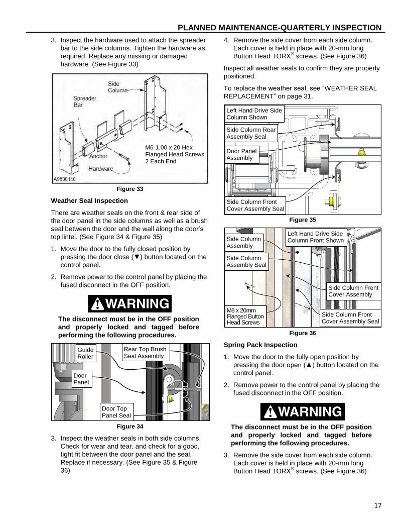
3. Inspect the hardware used to attach the spreader
bar to the side columns. Tighten the hardware as
required. Replace any missing or damaged
hardware. (See Figure 33)
Figure 33
Weather Seal Inspection
There are weather seals on the front & rear side of
the door panel in the side columns as well as a brush
seal between the door and the wall along the door’s
top lintel. (See Figure 34 & Figure 35)
1. Move the door to the fully closed position by
pressing the door close (▼) button located on the
control panel.
2. Remove power to the control panel by placing the
fused disconnect in the OFF position.
The disconnect must be in the OFF position
and properly locked and tagged before
performing the following procedures.
Figure 34
3. Inspect the weather seals in both side columns.
Check for wear and tear, and check for a good,
tight fit between the door panel and the seal.
Replace if necessary. (See Figure 35 & Figure
36)
4. Remove the side cover from each side column.
Each cover is held in place with 20-mm long
Button Head TORX® screws. (See Figure 36)
Inspect all weather seals to confirm they are properly
positioned.
To replace the weather seal, see “WEATHER SEAL
REPLACEMENT” on page 31.
Figure 35
Figure 36
Spring Pack Inspection
1. Move the door to the fully open position by
pressing the door open (▲) button located on the
control panel.
2. Remove power to the control panel by placing the
fused disconnect in the OFF position.
The disconnect must be in the OFF position
and properly locked and tagged before
performing the following procedures.
3. Remove the side cover from each side column.
Each cover is held in place with 20-mm long
Button Head TORX® screws. (See Figure 36)
Rear Top Brush Seal Assembly
Door Top Panel Seal
Guide Roller
Door Panel
Left Hand Drive Side Column Front Shown Side Column
Assembly
M8 x 20mm Flanged Button Head Screws
Side Column Front Cover Assembly Seal
Side Column Assembly Seal
Side Column Front Cover Assembly
Left Hand Drive Side Column Shown
Side Column Front Cover Assembly Seal
Side Column Rear Assembly Seal
Door Panel Assembly
M6-1.00 x 20 Hex Flanged Head Screws 2 Each End
PLANNED MAINTENANCE-QUARTERLY INSPECTION
18
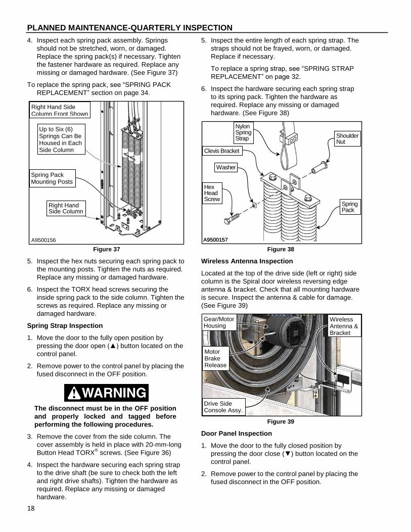
4. Inspect each spring pack assembly. Springs
should not be stretched, worn, or damaged.
Replace the spring pack(s) if necessary. Tighten
the fastener hardware as required. Replace any
missing or damaged hardware. (See Figure 37)
To replace the spring pack, see “SPRING PACK
REPLACEMENT” section on page 34.
Figure 37
5. Inspect the hex nuts securing each spring pack to
the mounting posts. Tighten the nuts as required.
Replace any missing or damaged hardware.
6. Inspect the TORX head screws securing the
inside spring pack to the side column. Tighten the
screws as required. Replace any missing or
damaged hardware.
Spring Strap Inspection
1. Move the door to the fully open position by
pressing the door open (▲) button located on the
control panel.
2. Remove power to the control panel by placing the
fused disconnect in the OFF position.
The disconnect must be in the OFF position
and properly locked and tagged before
performing the following procedures.
3. Remove the cover from the side column. The
cover assembly is held in place with 20-mm-long
Button Head TORX® screws. (See Figure 36)
4. Inspect the hardware securing each spring strap
to the drive shaft (be sure to check both the left
and right drive shafts). Tighten the hardware as
required. Replace any missing or damaged
hardware.
5. Inspect the entire length of each spring strap. The
straps should not be frayed, worn, or damaged.
Replace if necessary.
To replace a spring strap, see “SPRING STRAP
REPLACEMENT” on page 32.
6. Inspect the hardware securing each spring strap
to its spring pack. Tighten the hardware as
required. Replace any missing or damaged
hardware. (See Figure 38)
Figure 38
Wireless Antenna Inspection
Located at the top of the drive side (left or right) side
column is the Spiral door wireless reversing edge
antenna & bracket. Check that all mounting hardware
is secure. Inspect the antenna & cable for damage.
(See Figure 39)
Figure 39
Door Panel Inspection
1. Move the door to the fully closed position by
pressing the door close (▼) button located on the
control panel.
2. Remove power to the control panel by placing the
fused disconnect in the OFF position.
Gear/Motor Housing
Drive Side Console Assy.
Motor Brake Release
Wireless Antenna & Bracket
Up to Six (6) Springs Can Be Housed in Each Side Column
Right Hand Side Column
Right Hand Side Column Front Shown
Spring Pack Mounting Posts
A9500156
Nylon Spring Strap
Hex Head Screw
Spring Pack
Shoulder Nut
Washer
A9500157
Nylon Spring Strap
Spring Pack
Shoulder Nut
Washer
A9500157
Clevis Bracket

PLANNED MAINTENANCE-QUARTERLY INSPECTION
19
The disconnect must be in the OFF position
and properly locked and tagged before
performing the following procedures.
3. Remove the side covers from the side columns.
Each cover is held in place with 20-mm- long
Button Head TORX® screws. (See Figure 36)
4. Inspect the entire door panel assembly. Check for
damaged or missing hardware. Replace as
needed. Also check for loose hardware. Tighten
as required.
5. Check for any damaged door panels. Replace as
necessary.
To replace a door panel, see “DOOR PANEL
REPLACEMENT” section on page 30.
ROLLER & GUIDE WHEEL INSPECTION
6. Position clamps along both edges of the door
above & below the Lower Track Assembly Track
Cover to be removed to prevent unexpected door
movement as shown. (See Figure 40)
7. Individually remove the Lower Track Assembly
track covers 1 at a time to inspect the roller &
guide wheels. Reinstall each cover before
inspecting the next set of rollers/guides. The
covers are held in place with Button Head TORX®
screws. (See Figure 41)
Inspect the rollers and guides for damage or
wear. Replace as needed. (See Figure 41)
To replace a roller or guide, see “DOOR ROLLER
REPLACEMENT” section on page 35.
Figure 40
Figure 41
Lower Track
Hinge Roller
Guide Roller
Left Hand Drive Side Column Front Shown
Flanged Button Head Screws
Track Cover
Track Cover

PLANNED MAINTENANCE-QUARTERLY INSPECTION
20
8. Check that the door panel is level along the
bottom edge of the panel.
IMPORTANT: DO NOT check the door for level
by how it rests on the floor. With
the side columns plumb, square,
and level, the door will be level
when the bottom edge of the
panel is perpendicular to the side
columns.
A door panel is considered level when the ends of
the bottom edge are within ⅛ inch of each other.
To level the door panel, see “DOOR PANEL
ADJUSTMENT” section on page 24.
9. After all inspections are complete, reattach all
panels & covers.
Bottom Bar Reversing Edge Inspection
Inspect the entire length of the bottom bar reversing
edge seal for damage such as tears, holes, & for
missing or loose hardware. Inspect the edge itself.
DO NOT stand under the door when
performing the following test! If the
reversing edge sensor is not working
properly the door could strike the person
performing the procedure. Failure to stay
clear of it may cause damage or personal
injury! DO NOT use the door if the sensor is
not working properly.
1. Move the door to the open position by pressing
the door open (▲) button located on the control
panel.
2. Press the door close (▼) button.
3. When the door is a few feet from the fully closed
position, hit the rubber reversing edge that runs
along the bottom edge of the door. Stand outside
the photo eyes to avoid activating the photo eye
circuit. (See Figure 42)
Figure 42
If the reversing edge sensor is working correctly, the
door will reverse direction & move to the fully open
position. If the door was opened using a timer input,
the door will begin counting down on that timer.
When the door timer reaches 0 the door will again
begin to close, then reverse after the reversing edge
is activated.
If the reversing edge is activated 3 consecutive times
the door will open and remain open displaying F:361
“Edge Tripped” To reset the control system, see
“System Reset — Door Reversing Edge” on page 4.
If the reversing edge sensor is not working properly,
several issues may occur: the control system will
only allow the door to open, it will not reverse
direction after striking an object when closing, etc.
and the issue must be investigated further.
NOTE: A normal resistance measurement across
the reversing edge sensor will read
approximately 8.2 k-ohms. With the rubber
edge compressed, the resistance will drop
to about zero ohms.
4. Check the wires from the reversing edge cable
that go to the terminal block of the mobile unit.
Make sure that they are tightly secure. Inspect
terminal block for damage and replace any
missing or damaged hardware.(See Figure 43)
Figure 43
5. Inspect the rubber reversing edge. It should be in
good condition with no visible holes, cracks, or
tears. Replace the rubber reversing edge if
necessary.
For other specific issues, error codes, etc. refer to
the “System 4 Drive & Control” manual.
Bottom Edge
Bottom Bar Reversing Switch housed in Rubber Extrusion Assy

ADJUSTMENTS-PRIMARY DRIVE BELT
21
To replace the reversing edge, see “REVERSING
EDGE REPLACEMENT” on page 37.
Door Limit Inspection
See the Rytec System 4 Drive & Control Installation
& Owner’s Manual for the proper procedure for
setting the open and close door limits. The open &
close limit door positions are detailed in the
“ADJUSTMENT – DOOR LIMITS” section of that
manual.
Motor Brake & Release Cable Inspection
The power drive brake assembly is designed to act
as a parking brake when electrical power is turned off
to the motor. If the limit switches are set properly and
the door drifts past the set limits, the brake may need
to be replaced. Contact your RYTEC customer
support for further assistance. The motor brake
release cable also may need adjustment.
1. Move the door to the fully closed position by
pressing the door close (▼) button located on the
control panel.
2. Remove power to the control panel by placing the
fused disconnect in the OFF position.
The disconnect must be in the OFF position
and properly locked and tagged before
performing the following procedures.
3. Remove the side column cover from the side
column where the Brake Release is mounted. The
cover assembly is held in place with 20-mm-long
Button Head TORX® screws. (See Figure 36)
4. Make sure the brake release handle(s) is in good
working order and securely fastened to the left
side column and/or the opposite side wall.
Replace any missing or damaged hardware as
required. (See Figure 44)
Figure 44
5. Inspect the entire length of the brake release
cable(s) running from the brake release handle to
the electric brake mechanism located on the drive
motor assembly. The cable should not be frayed,
worn, or damaged. Replace if necessary. (See
Figure 45)
Figure 45
To replace the Brake Release Cable, see “BRAKE
RELEASE CABLE REPLACEMENT” on page 28.
6. Make sure the upper end of the cable is securely
fastened to the electric brake mechanism.
7. Inspect the cable clamp on the lower end of the
cable to ensure it is securely fastened to the
brake release handle. (See Figure 44)
8. Test the cable by pulling on the brake release
handle. Verify the electric brake mechanism is
disengaged by repositioning the door.
The tension on the cable should be tight enough to
disengage the brake when the handle is pulled, but
not so tight that the brake mechanism will not re-
engage once the handle is placed back against the
side column. Adjust the cable as required.
To adjust the brake release cable, see “BRAKE
RELEASE CABLE ADJUSTMENT” on page 25.
ADJUSTMENTS
PRIMARY DRIVE BELT
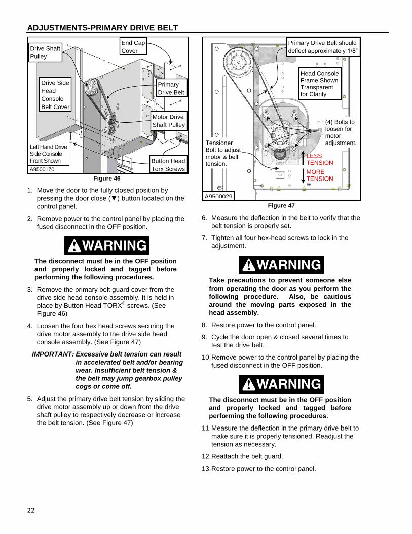
The primary drive belt that runs from the gearbox
pulley to the primary drive shaft pulley is behind the
drive belt guard located on the left end of the head
assembly. (See Figure 46)
Drive Side Console Assy.
Motor Brake Release Lever
Wireless Antenna & Bracket
Brake Proximity Switch & encoder located under the cover.
Motor Brake Release Cable
Gear/Motor Housing
ADJUSTMENTS-PRIMARY DRIVE BELT
22
Figure 46
1. Move the door to the fully closed position by
pressing the door close (▼) button located on the
control panel.
2. Remove power to the control panel by placing the
fused disconnect in the OFF position.
The disconnect must be in the OFF position
and properly locked and tagged before
performing the following procedures.
3. Remove the primary belt guard cover from the
drive side head console assembly. It is held in
place by Button Head TORX® screws. (See
Figure 46)
4. Loosen the four hex head screws securing the
drive motor assembly to the drive side head
console assembly. (See Figure 47)
IMPORTANT: Excessive belt tension can result
in accelerated belt and/or bearing
wear. Insufficient belt tension &
the belt may jump gearbox pulley
cogs or come off.
5. Adjust the primary drive belt tension by sliding the
drive motor assembly up or down from the drive
shaft pulley to respectively decrease or increase
the belt tension. (See Figure 47)
Figure 47
6. Measure the deflection in the belt to verify that the
belt tension is properly set.
7. Tighten all four hex-head screws to lock in the
adjustment.
Take precautions to prevent someone else
from operating the door as you perform the
following procedure. Also, be cautious
around the moving parts exposed in the
head assembly.
8. Restore power to the control panel.
9. Cycle the door open & closed several times to
test the drive belt.
10. Remove power to the control panel by placing the
fused disconnect in the OFF position.
The disconnect must be in the OFF position
and properly locked and tagged before
performing the following procedures.
11. Measure the deflection in the primary drive belt to
make sure it is properly tensioned. Readjust the
tension as necessary.
12. Reattach the belt guard.
13. Restore power to the control panel.
Primary
Drive Belt
Motor Drive
Shaft Pulley
Button Head
Torx Screws
Drive Side
Head
Console
Belt Cover
Left Hand Drive Side Console Front Shown
A9500170
End Cap
Cover Drive Shaft
Pulley
MORE TENSION
(4) Bolts to loosen for motor adjustment.
LESS TENSION
Primary Drive Belt should
deflect approximately 1/8”
Tensioner Bolt to adjust motor & belt tension.
Head Console Frame Shown Transparent for Clarity
A9500029

ADJUSTMENTS-SECONDARY DRIVE BELT
23
SECONDARY DRIVE BELT
There are two secondary drive belts. Each runs from
the drive shaft assembly down through its respective
side column. Belt tension is controlled with a guide
pulley at the bottom of the side column.
1. Move the door to the open position by pressing
the door open (▲) button located on the control
panel.
2. Remove power to the control panel by placing the
fused disconnect in the OFF position.
The disconnect must be in the OFF position
and properly locked and tagged before
performing the following procedures.
3. Remove the side column covers from the side
columns. Each cover is held in place with 20-mm-
long Button Head TORX® screws. (See Figure 61)
Belt tension should just be snug. It is adjusted by
repositioning the guide pulley bracket on the front
mounting post. Moving the pulley closer to the
base plate will increase belt tension. Moving the
pulley away from the base plate will decrease belt
tension. (See Figure 48)
IMPORTANT: Excessive belt tension can result
in accelerated belt and/or bearing
wear. Insufficient belt tension &
the belt may jump gearbox pulley
cogs or come off.
Figure 48
4. Lock in the belt tension by tightening the lower nut
against the bottom of the pulley bracket. (See
Figure 48)
5. The belt should be centered on the guide pulley.
To adjust the belt to the right or left, use the bolt
and nuts located on the tabs. To move the belt to
the right, adjust the left tab down. To move the
belt to the left, adjust the right tab down. Recheck
the belt tension when finished. (See Figure 48)
Take precautions to prevent someone else
from operating the door as you perform the
procedure. Also, be cautious around the
moving parts exposed in the side columns.
6. Tighten all hardware.
7. Restore power to the control panel.
8. Cycle the door completely several times to work
each drive belt.
9. Remove power to the control panel by placing the
fused disconnect in the OFF position.
The disconnect must be in the OFF position
and properly locked and tagged before
performing the following procedures.
10. Measure the deflection in each secondary drive
belt to make sure they are both properly
tensioned. Readjust the belt tension as
necessary.
11. Check the door panel for level and adjust the
panel if necessary. (See “DOOR PANEL
ADJUSTMENT” on page 24)
NOTE: Because the door is connected directly to
the secondary drive belts, it is important to
check the door for level after adjusting
either drive belt.
12. After all adjustments are complete, reattach the
side column covers.
13. Restore power to the control panel. Side Column Base Plate
Left Hand Drive Side Column Front Shown
Secondary Drive Belt
Belt Guide Pulley Assy
M8 x 40 Post
M8 Nuts: Pulley Tension controlled by upper nut on front post
Belt Guide Pulley Assy Adjusting Tabs

ADJUSTMENTS-DOOR PANEL
24
DOOR PANEL
To ensure the door operates smoothly and efficiently,
the door panel must be level between the side
columns. Before performing this procedure, the
secondary drive belts must both be properly
tensioned.
1. Move the door to the fully open position by
pressing the door open (▲) button located on the
control panel.
2. Remove power to the control panel by placing the
fused disconnect in the OFF position.
The disconnect must be in the OFF position
and properly locked and tagged before
performing the following procedures.
3. Remove the cover from the side column adjacent
to the corner of the door to be lowered. The cover
is held in place with Button Head TORX® screws.
(See Figure 61)
NOTE: Always lower the high side (corner) of the
door panel. Never raise the panel.
4. Release the tension on the secondary drive belt
by loosening the nuts that tension the guide pulley
bracket from both the front & rear mounting posts.
Remove it from the mounting post(s) if necessary.
(See Figure 48)
5. Level the door panel by re-indexing the secondary
drive belt on the upper drive pulley. To do this,
push on the smooth portion of the black toothed
belt facing you. Begin by sliding your hand up the
belt. A “wave” will begin to form near the top (by
secondary drive belt pulley) as shown. (See
Figure 49)
Figure 49
When the “wave” reaches the secondary drive
pulley, the belt will “jump” or “slip” as the wave
goes around the pulley. (See Figure 49 & Figure
50)
NOTE: Reposition the drive belt no more than one
notch (tooth) at a time.
Be careful not to get your fingers caught or
pinched between the upper drive pulley and
the secondary drive belt.
Figure 50
6. Reattach if necessary and adjust & set the belt
tension. Tighten the guide pulley bracket to the
mounting post.
To adjust the secondary drive belt tension see
“SECONDARY DRIVE BELT ADJUSTMENT”
section on page 23.
Take precautions to prevent someone else
from operating the door as you perform the
following procedure. Also, be cautious
around the moving parts exposed in the
head assembly.
7. Restore power to the control panel.
8. Cycle the door opened & closed several times.
9. Remove power to the control panel by placing the
fused disconnect in the OFF position.
The disconnect must be in the OFF position
and properly locked and tagged before
performing the following procedures.
10. Check the door panel for level. Repeat the above
procedure, as required, until the panel is level.
Left Hand Drive Side Column Front Shown
Secondary Drive Belt w/ “Wave”
Secondary Drive Belt Pulley
A9500207
Right Side
Drive Shaft
Secondary
Drive Pulley
Spring
Straps
Secondary
Drive Belt

REPLACEMENT PROCEDURES-PHOTO EYE ALIGNMENT
25
11. After all adjustments are complete, re-attach the
side column cover.
12. Restore power to the control panel.
PHOTO EYE ALIGNMENT
1. Move the door to the fully open position by
pressing the door open (▲) button located on the
control panel.
2. Remove power to the control panel by placing the
fused disconnect in the OFF position.
The disconnect must be in the OFF position
and properly locked and tagged before
performing the following procedures.
3. To align a photo eye, reposition the photo eye
where mounted as required.
To determine when the photo eyes are properly
aligned, see “Photo Eye Inspection” on page 10. If
photo eye replacement is necessary, see
“PHOTO EYE REPLACEMENT” section on page
37.
4. After all adjustments are complete, reattach the
side column covers.
5. Restore power to the control panel and reset
open & close door limits as necessary.
BRAKE RELEASE CABLE ADJUSTMENT
The cable that connects the brake mechanism to the
brake release handle is located in the left side
column and/or may be mounted remotely (on
opposite side wall).
1. Move the door to the fully closed position by
pressing the door close (▼) button located on the
control panel.
2. Remove power to the control panel by placing the
fused disconnect in the OFF position.
The disconnect must be in the OFF position
and properly locked and tagged before
performing the following procedures.
3. Remove the side column cover from the side
column assembly on the motor drive side. Each
cover is held in place with 20-mm- long Button
Head TORX® screws. (See Figure 61)
4. Locate the end of the cable passing through the
brake release handle. (See Figure 51)
5. With the brake handle fully extended (at 90
degrees) loosen the cable clamp and pull on the
free end of the cable to remove any slack. Then
slide the cable clamp against the eyelet and
tighten the clamp.
Figure 51
6. Check the tension of the cable by pulling on the
brake release handle.
7. Manually position the door panel to verify that the
electric brake disengages when the handle is
pulled. (The door should slide freely and
smoothly.)
8. Return the handle to the side column to re-
engage the brake and lock the door.
9. Attempt to manually move the door to verify that
the brake mechanism is set and working properly.
(The door should remain locked in place.)
10. After all adjustments are complete, reattach the
side column cover.
11. Restore power to the control panel.
REPLACEMENT PROCEDURES
PRIMARY DRIVE BELT
The primary drive belt that runs from the gearbox
pulley to the primary drive shaft pulley is located
behind the belt guard, on the left end of the head
assembly. (See Figure 52)
1. Move the door to the fully closed position by
pressing the door close (▼) button located on the
control panel.
2. Remove power to the control panel by placing the
fused disconnect in the OFF position.
The disconnect must be in the OFF position
and properly locked and tagged before
performing the following procedures.
Brake Cable
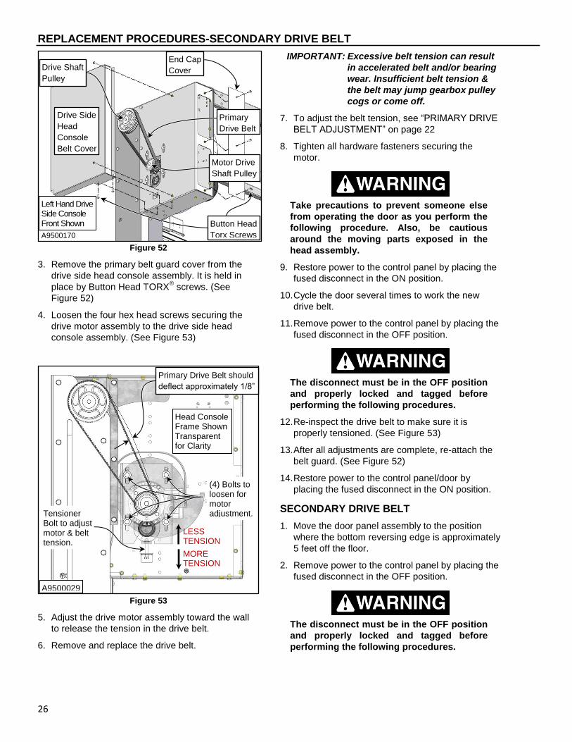
REPLACEMENT PROCEDURES-SECONDARY DRIVE BELT
26
Figure 52
3. Remove the primary belt guard cover from the
drive side head console assembly. It is held in
place by Button Head TORX® screws. (See
Figure 52)
4. Loosen the four hex head screws securing the
drive motor assembly to the drive side head
console assembly. (See Figure 53)
Figure 53
5. Adjust the drive motor assembly toward the wall
to release the tension in the drive belt.
6. Remove and replace the drive belt.
IMPORTANT: Excessive belt tension can result
in accelerated belt and/or bearing
wear. Insufficient belt tension &
the belt may jump gearbox pulley
cogs or come off.
7. To adjust the belt tension, see “PRIMARY DRIVE
BELT ADJUSTMENT” on page 22
8. Tighten all hardware fasteners securing the
motor.
Take precautions to prevent someone else
from operating the door as you perform the
following procedure. Also, be cautious
around the moving parts exposed in the
head assembly.
9. Restore power to the control panel by placing the
fused disconnect in the ON position.
10. Cycle the door several times to work the new
drive belt.
11. Remove power to the control panel by placing the
fused disconnect in the OFF position.
The disconnect must be in the OFF position
and properly locked and tagged before
performing the following procedures.
12. Re-inspect the drive belt to make sure it is
properly tensioned. (See Figure 53)
13. After all adjustments are complete, re-attach the
belt guard. (See Figure 52)
14. Restore power to the control panel/door by
placing the fused disconnect in the ON position.
SECONDARY DRIVE BELT
1. Move the door panel assembly to the position
where the bottom reversing edge is approximately
5 feet off the floor.
2. Remove power to the control panel by placing the
fused disconnect in the OFF position.
The disconnect must be in the OFF position
and properly locked and tagged before
performing the following procedures.
Primary
Drive Belt
Motor Drive
Shaft Pulley
Button Head
Torx Screws
Drive Side
Head
Console
Belt Cover
Left Hand Drive Side Console Front Shown
A9500170
End Cap
Cover Drive Shaft
Pulley
MORE TENSION
(4) Bolts to loosen for motor adjustment.
LESS TENSION
Primary Drive Belt should
deflect approximately 1/8”
Tensioner Bolt to adjust motor & belt tension.
Head Console Frame Shown Transparent for Clarity
A9500029

REPLACEMENT PROCEDURES-SECONDARY DRIVE BELT
27
3. Remove the cover from the side column assembly
containing the secondary drive belt to be
replaced. The cover is held in place with Button
Head TORX® screws. (See Figure 61)
4. Place clamps or brackets across the exposed
door track to secure the door and prevent it from
accidentally falling once belt tension is released.
(See Figure 54)
Figure 54
5. Release the tension from the secondary drive belt
by removing the guide pulley bracket from the
mounting posts. The pulley bracket is held in
place by a pair of nuts threaded onto the
mounting posts. (See Figure 55)
Figure 55
6. Loosen the hex head bolts on the end bracket to
release the secondary drive belt from the splice
block. The splice block pivots to allow the panels
to enter the radius at the top of the side column.
(See Figure 56)
Side Column Base Plate
Left Hand Drive Side Column Front Shown
Secondary Drive Belt
Belt Guide Pulley Assy
M8 x 40 Post
M8 Nuts: Pulley Tension controlled by upper nut on front post
Belt Guide Pulley Assy Adjusting Tabs

REPLACEMENT PROCEDURES-MOTOR BRAKE RELEASE CABLE
28
Figure 56
7. Remove the old secondary drive belt from around
the upper drive pulley and the guide pulley.
Discard the old belt.
8. Install the new secondary drive belt in the same
manner as the old belt.
9. Place the ends of the new drive belt between the
splice block & splice clamp. Then tighten the hex
bolts to clamp the belt to the end bracket.
10. Connect the guide pulley bracket assembly to the
mounting posts. Adjust the belt tension. (See
“SECONDARY DRIVE BELT ADJUSTMENT” on
page 23)
11. Remove all clamps and/or brackets securing the
door panel.
12. Release the electric brake mechanism by pulling
the brake release lever. Manually move the door
up and down several times to rotate the drive belt.
13. Inspect the belt for normal action as the door
travels up and down. Check the tension of the
belt. Readjust if necessary.
Take precautions to prevent someone else
from operating the door as you perform the
following procedure. Also, be cautious
around the moving parts exposed in the
side columns.
14. Restore power to the control panel/door by
placing the fused disconnect in the ON position.
15. Cycle the door several times to work the drive
belt.
16. Verify the new drive belt is working correctly.
17. Remove power to the control panel by placing the
fused disconnect in the OFF position.
The disconnect must be in the OFF position
and properly locked and tagged before
performing the following procedures.
18. Check the tension of the drive belt and readjust if
necessary.
19. Check that the door is level and adjust as needed.
(See “DOOR PANEL ADJUSTMENT” on page
24)
20. After all adjustments are complete, reattach the
side column cover.
21. Restore power to the control panel/door by
placing the fused disconnect in the ON position.
MOTOR BRAKE RELEASE CABLE
The motor brake release cable may need to be
replaced over the life of this door.
1. Move the door to the fully closed position by
pressing the door close (▼) button located on the
control panel.
2. Remove power to the control panel by placing the
fused disconnect in the OFF position.
The disconnect must be in the OFF position
and properly locked and tagged before
performing the following procedures.
Splice Block
(2) Bolts and nylock Nuts hold Splice Block
End Bracket Assembly
End Bracket Assembly
Secondary Drive Belt
Splice Block
Belt Guide Pulley Assy
Left Hand Side Column Shown
Right Hand Side Panel Assy Shown
M8 x 40 Post
M8 Nuts: Pulley Tension controlled by upper nut on front post
Nut
Splice Clamp

REPLACEMENT PROCEDURES-MOTOR BRAKE RELEASE CABLE
29
3. On the door’s drive side remove the cover from
the side column assembly. The cover is held in
place with Button Head TORX® screws. (See
Figure 61)
4. Disconnect the old brake release cable from the
electric brake mechanism by removing the cable
clamps, washers, and spring. Take note of the
order & how all items are assembled &
disassembled. Save all hardware. (See Figure 57
& Figure 59)
Figure 57
Figure 58
5. Remove & save the cable clamp at the handle
end of the cable. Pull the old cable out of the
head assembly & side column. Then discard the
old cable. (See Figure 57 & Figure 58)
6. Install the new brake release cable, routing it the
same as the old cable. Be sure to feed the cable
through the cable jacket that runs between the
side column & the motor gearbox. (See Figure 58
& Figure 59)
Figure 59
7. Using the saved hardware, connect the upper end
of the cable to the electric brake mechanism in
the reverse order the old cable was removed.
(See Figure 57 & Figure 59)
8. With the brake release handle fully extended out
or at 90 degrees, feed the cable through the
eyelet in the bottom of the handle. Slide a crimp
nut over the end of the cable with the nut tight
against the eyelet. Then tighten down the
setscrew with the majority of slack removed from
the cable. (See Figure 58)
9. Pull the handle several times to work the new
cable. Check the action of the electric brake
mechanism for proper travel. Verify that the door
can be repositioned when the brake release
handle is pulled. Reposition the cable clamp if
necessary.
10. After all adjustments are complete, cut the cable
to final length, an inch or two past the cable
clamp. (See Figure 58)
11. Install the side column cover.
12. Restore power to the control panel/door by
placing the fused disconnect in the ON position.
Brake Cable
Cable Clamp
Brake Release Cable
A9500181
Spring
Cable Jacket
Washer
Brake Release Handle
Electric Brake Release Lever
Drive Side Console Assy.
Motor Brake Release Lever
Wireless Antenna & Bracket
Brake Proximity Switch & encoder located under the cover.
Motor Brake Release Cable
Gear/Motor Housing

REPLACEMENT PROCEDURES-DOOR PANEL
30
DOOR PANEL
1. Place the door in “JOG MODE”: Press and hold
the RESET (●) and CLOSE (▼) arrow until the
control panel reads “JOG MODE”. Press the
OPEN (▲) arrow until the desired height is
reached. To place the door back into operational
mode, repeat the above process.
2. Remove power to the control panel by placing the
fused disconnect in the OFF position.
The disconnect must be in the OFF position
and properly locked and tagged before
performing the following procedures.
Take precautions to prevent someone else
from operating the door as you perform the
following procedure. Also, be cautious
around the moving parts exposed in the
side columns.
3. Remove the cover from each side column
assembly. The cover is held in place with Button
Head TORX® screws. (See Figure 61)
Use two clamps or brackets on each end of
the door panel assembly to prevent upward
or downward movement. Serious injury may
result from using improper procedure.
4. Position clamps or brackets along both edges of
the door above and below the panel to be
removed as shown to prevent unexpected door
movement. (See Figure 60)
Figure 60
5. At the ends of the door panel to be replaced,
remove the two Button Head TORX® screws
securing each hinge plate to the panel. (See
Figure 60)
6. Carefully break free the rubber seal from between
the adjoining panels.
7. Slip the panel to be removed out through the back
side of the door opening. (Sliding the panel to the
left or right will allow the panel to clear the track.)
8. Install the new door panel in the reverse order
that the old panel was removed.
9. After screwing the hinge plates to the new panel,
reattach the rubber seals. Place a small amount
of adhesive near the end of the rubber seal to
prevent contraction of the seal. A screen roller will
assist the installation of the rubber seal. Refer to
the Spiral Installation Manual.
10. Remove clamps and/or brackets from the tracks.
11. Release the brake by pulling the brake release
lever. Manually move the door up and down
several times. Verify that the door panel and
spring packs function normally. Make any
necessary adjustment.
Panel to be replaced
Rubber Seal

REPLACEMENT PROCEDURES-WEATHER SEAL REPLACEMENT
31
Take precautions to prevent someone else
from operating the door as you perform the
following procedure. Also, be cautious
around the moving parts exposed in the
head assembly.
12. Restore power to the control panel/door by
placing the fused disconnect in the ON position.
13. Operate the door several times to verify that the
door panel functions normally. Adjust & repeat
this procedure as necessary.
WEATHER SEAL REPLACEMENT
1. Move the door to the fully opened position by
pressing the door open (▲) button located on the
control panel.
2. Remove power to the control panel by placing the
fused disconnect in the OFF position.
The disconnect must be in the OFF position
and properly locked and tagged before
performing the following procedures.
3. Remove the side column cover from the side
column assembly containing the weather seal to
be replaced. The cover is held in place with
Button Head TORX® screws. (See Figure 61)
Figure 61
4. There is a length of weather seal on both the side
column cover and the side column. Each weather
seal can be removed by pulling on either end of
the seal, while working toward the opposite end.
(See Figure 62)
5. Attach the new weather seal in the opposite
manner the old seal was removed. Make sure the
seal is firmly seated along the edge. (See Figure
61 & Figure 62)
Left Hand Drive Side Column Front Shown
Side Column Assembly
Side Column Assembly Seal
Side Column Front Cover Assembly
M8 x 20mm Flanged Button Head Screws
Side Column Front Cover Assembly Seal

REPLACEMENT PROCEDURES-SPRING STRAP REPLACEMENT
32
Figure 62
6. Attach the side column cover assembly to the
side column assembly.
7. Restore power to the control panel/door by
placing the fused disconnect in the ON position.
8. Confirm the new weather seal properly seals
against the door panel. Adjust as necessary.
SPRING STRAP REPLACEMENT
1. Move the door to the fully opened position by
pressing the door open (▲) button located on the
control panel.
2. Remove power to the control panel by placing the
fused disconnect in the OFF position.
The disconnect must be in the OFF position
and properly locked and tagged before
performing the following procedures.
3. Remove the side column cover assembly from the
side column assembly. The cover is held in place
with 20-mm-long, Button Head TORX® screws.
(See Figure 61)
Figure 63
4. Remove the associated end cap from the head
console assembly to expose the upper end of the
spring strap. Each end cap is held in place with
three, M8-20mm long, Button Head TORX®
screws. (See Figure 63)
Figure 64
5. Disconnect the associated spring pack assembly
from the base plate. To retain the preload setting
of the spring pack, loosen only the lower hex nut
on each mounting post. (See Figure 64)
6. To release the strap from the spring pack, remove
the screw & the shoulder nut passing through the
clevis bracket at the top of the spring pack. Save
all hardware. (See Figure 65)
Wall
Lower Track Assembly
Base Plate Assembly
Side Column Assembly- Outer Wall
Left Hand Side Column Shown
Door Opening
Weather Seal
M8 x 20mm Flanged Button Head Screws
Left Hand Drive Side Console Assy. Shown
Console Assembly End Cap
Side Column Front Cover Assembly

REPLACEMENT PROCEDURES-SPRING STRAP REPLACEMENT
33
Figure 65
It is critical for you to remember the exact
number of times the old spring strap is
“dead wrapped” around the drive shaft.
Otherwise, if the new strap is not dead
wrapped exactly as the old strap, severe
damage can result to the drive system.
7. To release the spring strap from the drive shaft,
first unwind the strap from around the drive shaft.
8. Then remove the steel end cap/plate and all
associated hardware used to secure the strap to
the shaft. Save all hardware. (See Figure 63 &
Figure 66)
NOTE: Depending on the rotated position of the
drive shaft, you might not have direct
access to the hardware securing the
spring strap to the drive shaft. To expose
the mounting hardware, first release the
electric brake mechanism and then
manually reposition the door until the drive
shaft rotates the mounting hardware
toward the opening you are working
through. Reset the brake once the
mounting hardware is rotated toward the
opening.
9. Attach the new strap to the drive shaft using the
saved hardware. The hardware must be securely
fastened to ensure that the spring strap does not
disconnect from the drive shaft.
Figure 66
10. “Dead wrap” the new strap around the drive shaft.
Make sure the strap comes off the same direction
as the strap previous. Wrap the new strap around
the drive shaft the same number of times the old
strap was dead wrapped around the shaft. (If the
door was moved to rotate the clamp plates, move
the door back to its original position to ensure the
belt is wrapped correctly.)
It is critical that the new spring strap be
“dead wrapped” around the drive shaft the
correct number of times. The strap wrapped
so that it comes off the front of the drive
shaft. Otherwise, the door will not open or
close properly, and damage to the drive
system could result.
11. Attach the loop end of the new spring strap to the
spring pack using the saved hardware. Make sure
the strap is hanging straight and not twisted. (See
Figure 65)
12. Attach the spring pack to the mounting posts on
the base plate. Tighten the lower nuts against the
bottom of the mounting plate to retain the preload
setting of the spring pack. (See Figure 67)
NOTE: If more than one spring pack is used, face
the forked mounting plates toward each
other and use plastic cable zip ties to help
pull the mounting plates tight against the
posts.
Nylon Spring Strap
Hex Head Screw
Spring Pack
Shoulder Nut
Washer
A9500157
Clevis Bracket
A9500207
Right Side
Drive Shaft
Secondary
Drive Pulley
Spring
Straps
Secondary
Drive Belt
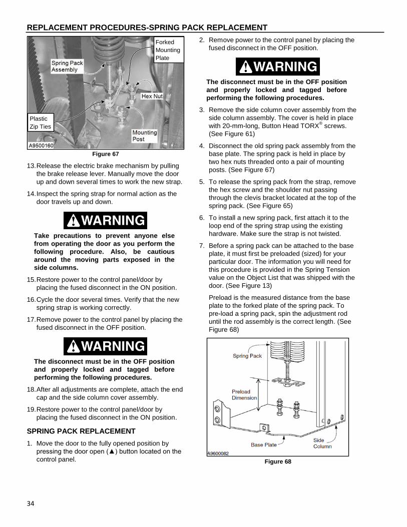
REPLACEMENT PROCEDURES-SPRING PACK REPLACEMENT
34
Figure 67
13. Release the electric brake mechanism by pulling
the brake release lever. Manually move the door
up and down several times to work the new strap.
14. Inspect the spring strap for normal action as the
door travels up and down.
Take precautions to prevent anyone else
from operating the door as you perform the
following procedure. Also, be cautious
around the moving parts exposed in the
side columns.
15. Restore power to the control panel/door by
placing the fused disconnect in the ON position.
16. Cycle the door several times. Verify that the new
spring strap is working correctly.
17. Remove power to the control panel by placing the
fused disconnect in the OFF position.
The disconnect must be in the OFF position
and properly locked and tagged before
performing the following procedures.
18. After all adjustments are complete, attach the end
cap and the side column cover assembly.
19. Restore power to the control panel/door by
placing the fused disconnect in the ON position.
SPRING PACK REPLACEMENT
1. Move the door to the fully opened position by
pressing the door open (▲) button located on the
control panel.
2. Remove power to the control panel by placing the
fused disconnect in the OFF position.
The disconnect must be in the OFF position
and properly locked and tagged before
performing the following procedures.
3. Remove the side column cover assembly from the
side column assembly. The cover is held in place
with 20-mm-long, Button Head TORX® screws.
(See Figure 61)
4. Disconnect the old spring pack assembly from the
base plate. The spring pack is held in place by
two hex nuts threaded onto a pair of mounting
posts. (See Figure 67)
5. To release the spring pack from the strap, remove
the hex screw and the shoulder nut passing
through the clevis bracket located at the top of the
spring pack. (See Figure 65)
6. To install a new spring pack, first attach it to the
loop end of the spring strap using the existing
hardware. Make sure the strap is not twisted.
7. Before a spring pack can be attached to the base
plate, it must first be preloaded (sized) for your
particular door. The information you will need for
this procedure is provided in the Spring Tension
value on the Object List that was shipped with the
door. (See Figure 13)
Preload is the measured distance from the base
plate to the forked plate of the spring pack. To
pre-load a spring pack, spin the adjustment rod
until the rod assembly is the correct length. (See
Figure 68)
Figure 68
Plastic
Zip Ties
Forked
Mounting
Plate

REPLACEMENT PROCEDURES-DOOR ROLLER REPLACEMENT
35
8. Attach the spring pack to the mounting posts on
the base plate. To retain the preload setting,
tighten only the lower nuts against the bottom of
the mounting plate — do not adjust the upper pair
of nuts. (See Figure 67)
NOTE: Make sure the spring strap is hanging
straight and not twisted. Also, if more than
one spring pack is used in the side
column, face the forked mounting plates
toward each other and use plastic cable
ties to hold the mounting plates tight
against the posts.
9. Release the electric brake mechanism by pulling
the brake release lever. Manually move the door
up and down several times to stretch and work
the new spring pack.
10. Inspect the spring pack for normal action as the
door travels up and down. Make any necessary
adjustments.
Take precautions to prevent someone else
from operating the door as you perform the
following procedure. Also, be cautious
around the moving parts exposed in the
side columns.
11. Restore power to the control panel/door by
placing the fused disconnect in the ON position.
12. Cycle the door several times. Verify that the new
spring pack is working correctly.
13. Remove power to the control panel by placing the
fused disconnect in the OFF position.
The disconnect must be in the OFF position
and properly locked and tagged before
performing the following procedures.
14. After all adjustments are complete, attach the
cover to the side column.
15. Restore power to the control panel/door by
placing the fused disconnect in the ON position.
DOOR ROLLER REPLACEMENT
1. Place the door in “JOG MODE”: Press and hold
the RESET (●) and CLOSE (▼) arrow until the
control panel reads “JOG MODE”. Press the
OPEN (▲) arrow until the desired height is
reached. To place the door back into operational
mode, repeat the above process.
2. Remove power to the control panel by placing the
fused disconnect in the OFF position.
The disconnect must be in the OFF position
and properly locked and tagged before
performing the following procedures.
3. Remove the side column cover from the side
column assembly containing the roller or guide
wheel to be replaced. The cover is held in place
with Button Head TORX® screws. (See Figure 61)
Use two clamps on each end to prevent
upward or downward movement. Serious
injury may result from improper procedure.
4. Position clamps or bracket along both edges of
the door above the Lower Track Assembly track
cover to be removed for roller wheel/guide wheel
replacement to prevent unexpected door
movement as shown. (See Figure 69)
Figure 69
Lower Track Assembly Track Cover
Roller wheel(s) to be replaced
Vise Grip or other locking tool

REPLACEMENT PROCEDURES-DOOR ROLLER REPLACEMENT
36
Take precautions to prevent someone else
from operating the door as you perform the
following procedure. Also, be cautious
around the moving parts exposed in the
head assembly.
5. Individually remove the Lower Track Assembly
Cover to replace the roller and/or guide wheel as
necessary. The cover is held in place with Button
Head TORX® screws. (See Figure 70)
6. Remove the Button Head TORX screws from the
hinge plates above & below the roller or guide
wheel to be removed. (See Figure 70)
Figure 70
7. To remove the roller, loosen and remove the nut
on the end of the roller. Then slide the roller off
the end of the axle. (See Figure 70 & Figure 71)
NOTE: If the axle is bent or damaged, remove it,
by punching out the small spring pin that
locks the axle in the hinge.
Figure 71
8. Install the new roller, and reassemble the door
and the track in the reverse order of disassembly.
9. Remove the clamps from the track.
10. Release the motor electric brake mechanism by
pulling the brake release lever. Manually move
the door up and down several times to test the
new roller. Make any adjustments necessary.
Take precautions to prevent someone else
from operating the door as you perform the
following procedure. Also, be cautious
around the moving parts exposed in the
head assembly.
11. Restore power to the control panel by placing the
fused disconnect in the ON position.
12. Cycle the door open & closed several times.
Verify that the new roller is working correctly.
13. Remove power to the control panel by placing the
fused disconnect in the OFF position.
The disconnect must be in the OFF position
and properly locked and tagged before
performing the following procedures.
14. Make adjustments as needed & repeat testing.
15. When the door is operating properly, reattach
both side column covers.
16. Restore power to the control panel by placing the
fused disconnect in the ON position.
Lower Track
Hinge Roller
Guide Roller
Left Hand Side Column Front Shown
Flanged Button Head Torx Screws
Track Cover
Flanged Button Head Torx Screws Removed
Move Hinge out/away from door panel to access nut
Flanged Button Head Torx Screws
Hinge Plate

REPLACEMENT PROCEDURES-PHOTO EYE REPLACEMENT
37
PHOTO EYE REPLACEMENT
When replacing the photo eyes, note that the emitter
modules are located in the left-front & right-rear
corners of the door, and the receiver modules are
located in the right-front & left-rear corners of the
door. The emitter & receiver modules located in the
side columns of the door need to be replaced with
the same identical modules. When replacing both
modules it is best to replace one module at a time to
avoid any errors.
The photo eyes must be installed with the emitter
modules & receiver modules mounted diagonally
across from each other. This will avoid one set of
eyes from interfering with the other set of eyes.
Also, the front and rear sets of photo eyes and their
associated wire cables are interchangeable — but
each set of eyes is uniquely wired.
1. Move the door to the fully opened position by
pressing the door open (▲) button located on the
control panel.
2. Remove power to the control panel by placing the
fused disconnect in the OFF position.
The disconnect must be in the OFF position
and properly locked and tagged before
performing the following procedures.
3. Remove the side column cover from the side
column assembly containing the photo eye
module to be replaced. The cover is held in place
by Button Head TORX® screws. (See Figure 61)
4. Remove the photo eye module from the side
column assembly that needs to be replaced. Only
replace one at a time.
5. Disconnect the module from the wire & replace it
with the new module.
6. Reinstall the new module into the side column
assembly. Repeat this for the module in the
opposite side column assembly as necessary.
7. Check and clean photo eye modules as
necessary. See “Cleaning Photo Eyes” section on
page 11.
8. Align the photo eyes per the “Photo Eye
Alignment” section on page 25.
9. Restore power to the control panel by placing the
fused disconnect in the ON position.
10. Confirm that the photo eyes are operating
properly. See “PHOTO EYE INSPECTION”
section for this procedure on page 10. Repeat this
process and adjust until the photo eyes are
operating correctly.
11. Reinstall all covers & safety guards.
Cleaning Photo Eyes
A dirty photo eye lens can cause a photo eye module
to fail or operate intermittently. After any work is
performed on either set of photo eyes, it is
recommended that the lens on each photo eye be
cleaned using a clean, soft cloth and household
window cleaner.
REVERSING EDGE REPLACEMENT
1. Move the door to a comfortable position for
working on replacing the bottom bar reversing
edge. Do this by jogging or releasing the brake to
position the door.
2. Remove power to the control panel by placing the
fused disconnect in the OFF position.
The disconnect must be in the OFF position
and properly locked and tagged before
performing the following procedures.
3. Remove the side column cover from the side
column assemblies. The cover is held in place
with Button Head TORX® screws. (See Figure 61)
An appropriate number of clamps must be
placed across both door tracks to prevent
the door panel from moving while
performing the following procedure.
4. Position clamps or brackets on both sides of the
door to the uppermost sections of track. (See
Figure 72)
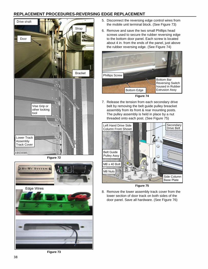
REPLACEMENT PROCEDURES-REVERSING EDGE REPLACEMENT
38
Figure 72
Figure 73
5. Disconnect the reversing edge control wires from
the mobile unit terminal block. (See Figure 73)
6. Remove and save the two small Phillips head
screws used to secure the rubber reversing edge
to the bottom door panel. Each screw is located
about 4 in. from the ends of the panel, just above
the rubber reversing edge. (See Figure 74)
Figure 74
7. Release the tension from each secondary drive
belt by removing the belt guide pulley breacket
assembly from its front & rear mounting posts.
The pulley assembly is held in place by a nut
threaded onto each post. (See Figure 75)
Figure 75
8. Remove the lower assembly track cover from the
lower section of door track on both sides of the
door panel. Save all hardware. (See Figure 76)
Lower Track Assembly Track Cover
Vise Grip or other locking tool
Side Column Base Plate
Left Hand Drive Side Column Front Shown
Secondary Drive Belt
Belt Guide Pulley Assy
M8 x 40 Bolt
M8 Nuts
Bottom Edge
Bottom Bar Reversing Switch housed in Rubber Extrusion Assy
Phillips Screw

REPLACEMENT PROCEDURES-WIRELESS ANTENNA BRACKET/ENCODER
39
Figure 76
9. Lift the lower door panel away from the door
opening until the reversing edge just clears the
front of each side column.
10. Slide the reversing edge out of the T-channel it
hangs from along the bottom edge of the door.
11. Install the new reversing edge in the reverse
order as the old edge was removed. Use all
saved hardware. Make sure to center the
reversing edge on the door panel before
reinstalling the small Phillips head screws.
12. Connect both drive belt pulley guide brackets to
the mounting posts in the bottom of the side
columns.
13. Inspect the tension on each secondary drive belt.
If adjustment is necessary, see “SECONDARY
DRIVE BELT ADJUSTMENT” on page 23.
14. Reattach the spring packs to the mounting posts.
Make sure the strap that each spring pack hangs
from is not twisted.
15. Release the electric brake mechanism by pulling
the brake release lever. Manually move the door
up and down several times to ensure the panel
rolls smoothly. Adjust as necessary.
Take precautions to prevent someone else
from operating the door as you perform the
following procedure. Also, be cautious
around the moving parts exposed in the
head assembly.
16. Reengage the brake release mechanism.
17. Restore power to the control panel by placing the
fused disconnect in the ON position.
18. Cycle the door several times. Verify that the door
panel rolls smoothly and is working correctly.
19. Test the new reversing edge to make sure that it
is operating properly. See “REVERSING EDGE
INSPECTION” on page 20.
20. Remove power to the control panel by placing the
fused disconnect in the OFF position.
The disconnect must be in the OFF position
and properly locked and tagged before
performing the following procedures.
21. After all adjustments are complete, attach the side
column covers.
22. Restore power to the control panel by placing the
fused disconnect in the ON position.
WIRELESS ANTENNA BRACKET/ENCODER
Located at the top of the drive side (left or right) side
column assembly is the Spiral door wireless antenna
bracket assembly. (See Figure 77)
Figure 77
If the wireless bracket is damaged remove the
portion of the bracket that is damaged and replace it.
If the wireless antenna is damaged the wireless
encoder assembly will need to be replaced. Part
#R00141120
To replace the wireless encoder, the brake cover will
need to be removed to access the wireless encoder.
(See Figure 78)
Lower Track
Hinge Roller
Guide Roller
Left Hand Side Column Front Shown
Flanged Button Head Torx Screws
Track Cover
Flanged Button Head Torx Screws
Hinge Plate
Antenna Cable
Drive Side Console Assy. LH Shown
Motor Brake Release Lever
Wireless Antenna & Bracket
Brake Proximity Switch & encoder located under the cover.
Motor Brake Release Cable
Gear/Motor Housing
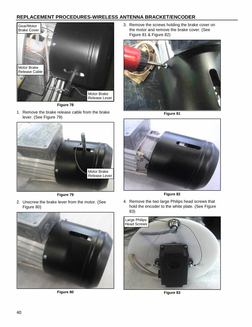
REPLACEMENT PROCEDURES-WIRELESS ANTENNA BRACKET/ENCODER
40
Figure 78
1. Remove the brake release cable from the brake
lever. (See Figure 79)
Figure 79
2. Unscrew the brake lever from the motor. (See
Figure 80)
Figure 80
3. Remove the screws holding the brake cover on
the motor and remove the brake cover. (See
Figure 81 & Figure 82)
Figure 81
Figure 82
4. Remove the two large Philips head screws that
hold the encoder to the white plate. (See Figure
83)
Figure 83
Motor Brake Release Lever
Motor Brake Release Cable
Gear/Motor Brake Cover
Motor Brake Release Lever
Large Philips Head Screws

REPLACEMENT PROCEDURES-VISION PANEL MAINTENANCE
41
5. Check the 2 set screws (1.5mm) on the hub to
make sure the encoder hub is tight to the motor
shaft. (See Figure 84)
Figure 84
6. Replace with the new wireless encoder.
7. Route the cables through the notch in the white
plastic plate and re-install the brake cover. (See
Figure 85)
Figure 85
VISION PANEL MAINTENANCE
Vision Panel (Slat) Cleaning
The Vision Panels should be inspected on a daily
basis for dirt, grease, etc. & any abrasions. Cleaning
must be done when dirt, grease, abrasions, or
anything else that diminishes panel clarity is
observed. Follow the procedure(s) as necessary:
1. Remove power to the control panel by placing the
fused disconnect in the OFF position.
The disconnect must be in the OFF position
and properly locked and tagged before
performing the following procedures.
ROUTINE CLEANING
2. Rinse with flowing water.
3. Clean with warm water & a small amount of mild
non-abrasive soap (dish soap).
4. Lightly rinse vision panels using a water spray.
5. Remove excess water using a clean and dry
Micro-fiber or lint free cloth. If practical, use high
velocity fan or leaf blower to blow the panels dry
for best results.
6. Wipe any additional moisture with dry micro-fiber
or lint free cloth. If practical, use high velocity fan
or leaf blower to blow the panels dry for best
results.
OCCASIONAL HEAVY CLEANING & FINE
SCRATCH REMOVAL
1. Remove all surface dirt & dust with warm water
spray.
2. Mix a mild non-abrasive soap (dish soap) into a
bucket of warm water.
3. Gently wash using a microfiber or lint free cloth
keeping the cloth sudsy at all times.
4. Lightly rinse vision panels using a water spray.
5. Remove excess water using a clean and dry
microfiber or lint free cloth. If practical, use high
velocity fan or leaf blower to blow the panels dry
for best results.
6. Over the counter products can be used to polish
the vision panels. Products such as (Novus Polish
#2 – www.novuspolish.com) are designed
specifically for polycarbonate windows and will
help maintain clarity and shine of the vision
panels. Follow the instructions on the product for
the proper application.
NOTE: The product must be non-abrasive and
designed specifically for polycarbonate
windows. Avoid the use of abrasive
cleaners, squeegees and/or other cleaning
implements that may mar or gouge the
coating.
Cleaning Agents Found To Be Compatible w/
Lexan™ Sheets:
AQUEOUS SOLUTIONS OF DETERGENTS:
Top Job2
Mr. Clean2
Joy2
Formula 4094
Fantastik3
™ Trademark of SABIC Innovative Plastics IP BV 2 Registered Trademark of Proctor & Gamble.
3 Registered Trademark of Texize, Division of
Norton Norwich Products Inc. 4 Registered Trademark of the Clorox Company.
Check Set Screws
Notch for routing cables

REPLACEMENT PROCEDURES-VISION PANEL MAINTENANCE
42
ORGANIC SOLVENTS:
Butyl Cellosolve Hexcel, F.O. 554 Kerosene Neleco-Placer Naphtha (VM&P) Grade Turco 5042
ALCOHOLS:
Methanol and Isopropyl
All residual organic solvents should be removed with
a secondary rinse.
GRAFFITI REMOVAL:
A) Butyl Cellosolve (for removal of paints, marking
pen inks, lipstick, etc.). The use of masking
tape, adhesive tape or lint removal tools works
well for lifting off old weathered paints.
B) To remove labels, stickers, etc., the use of
kerosene or VM&P naphtha are generally
effective.
When the solvent will not penetrate sticker material,
apply heat (hair dryer) to soften the adhesive and
promote removal.
Vision Panel (Slat) Cleaning
Novus 1
PLASTIC CLEAN & SHINE
1. Remove surface dust with soft cloth.
2. Shake well. Apply a light mist of polish.
3. Spread evenly over the entire surface.
4. Buff with a clean, soft, lint-free cloth.
If the surface is extremely dirty, apply Novus 1
liberally and wipe using long, sweeping strokes. Do
not use pressure at this time or large dirt particles
may scratch the Lexan™.
Re-apply Novus 1 Polish using short, circular strokes
with a clean portion of the cloth.
When the surface is thoroughly clean and uniformly
covered, buff to a slippery glaze with a clean portion
of the cloth. Surfaces buffed to a high glaze are more
resistant to dust and future scratching.
Reapply Novus 1 regularly to maintain the antistatic,
smudge and scratch resistant properties.
Novus 2
FINE SCRATCH REMOVER
Observe condition of the surface to be treated. The
deeper the scratches, the greater the pressure
required to remove them. If the surface is dirty, clean
with NOVUS No.1 before applying NOVUS No. 2.
1. Shake well. Test in an inconspicuous area.
2. Remove surface dust with clean, soft cloth.
3. Apply polish in circular motion until dry.
4. Buff with a clean cloth. Repeat as necessary.
Apply NOVUS No. 2 liberally. Using a clean, soft
cloth, polish with a firm back-and-forth motion at right
angles to the scratches. Keep the cloth saturated
with polish at all times.
When the worst scratches have been polished out,
reapply NOVUS No.2 uniformly in a circular motion to
the entire surface using short, circular strokes and
light pressure. Allow to dry to a light haze.
Using a clean portion of the cloth, buff the surface to
a slippery glaze using firm, short strokes. This
procedure is imperative in achieving the best results.
For heavy scratches, multiple applications of NOVUS
No. 2 or application of NOVUS No. 3 may be
required. Follow with NOVUS No. 1 for best results.
Novus 3
HEAVY SCRATCH REMOVER
1. Shake well. Test in an inconspicuous area.
2. Remove surface dust with a clean, soft cloth.
3. Using a clean, soft cloth, apply Novus 3 with firm
back and forth strokes at right angle to visible
scratches. Reapply polish as needed.
4. Continue polishing until only the fine scratches
remain. Using a cloth, remove all of the remaining
polish.
5. Apply Novus 2 in a circular motion using a clean
cloth. Follow directions on the Novus 2 bottle.
Apply Novus 3 liberally. Using a clean, soft cloth,
polish with a firm back-and-forth motion at right
angles to the scratches. Keep the cloth saturated
with polish at all times.
Continue polishing until only fine scratches remain.
Using a cloth, remove all remaining polish, this is
very important!
Using a clean cloth, apply Novus 2 in a circular
motion uniformly to entire surface. Polish using light
pressure until Novus 2 dries to a light haze.

PARTS LIST-PARTS ORDERING INFORMATION
43
Using a clean portion of the cloth, buff the surface
clean. Follow with Novus 1 for best results.
™ Trademark of SABIC Innovative Plastics IP BV
PARTS LIST
PARTS ORDERING INFORMATION
How to Order Parts
1. Identify the parts required by referring to the
following pages for part numbers and part
descriptions.
2. To place an order, contact your local Rytec
representative or the Rytec Technical Support
Department at 800-628-1909 or 262-677-2058
(fax). Rytec Corporation also has an on-line store
at WWW.Rytecparts.com access to this on-line
store requires an invitation from Rytec. The on-
line store is open 24/7, 365 days. Some items are
available to ship next day. Not all Rytec parts are
carried in the on-line store.
3. To ensure the correct parts are shipped, please
include the serial number of your door with the
order. The serial number is located on the front of
both the left and right side column covers at about
eye level, on the drive motor gearbox in the head
assembly, or on the door of the System 4 Control
Panel. All these serial numbers should match.
(See Figure 86)
Figure 86
Substitute Parts
Due to special engineering and product
enhancement, the actual parts used on your door
may be different from those shown in this manual.
Also, if a part has been improved in design and bears
a revised part number, the improved part will be
substituted for the part ordered.
Return of Parts
Rytec will not accept the return of any parts unless
they are accompanied by a Return Merchandise
Authorization (RMA) form.
Before returning any parts, you must first contact the
Rytec Technical Support Department to obtain
authorization and an RMA number.
IMPORTANT: Obtain an incident number from
the Rytec Technical Support
Technician.
RYTEC TECHNCIAL KNOWLEDGE CENTER
At WWW.Rytecdoors.com under the “Contact Us”
pull down tab, a link to the Rytec Technical
Knowledge Center can be found by selecting the
“Customer Support” option. You will be directed to
the Customer Support webpage. Within the
“Technical Documents and Manuals” section you will
find the link “Rytec Technical Knowledge Center”.
This knowledge center contains on-line manuals,
service bulletins, and video presentations of various
Rytec models and repair information.
Motor-Gear Drive
Fused Disconnect (By Others)
System 4 Control Panel
Side Columns with Lower Track Assemblies
Door Assembly

NOTES
44

PARTS LIST-SPIRAL DOOR ASSEMBLY-LAYOUT
45
SPIRAL DOOR ASSEMBLY-LAYOUT
Left Hand Drive Door Assembly Shown
1
14
3
4
E (See #17 “Brake Release Assembly” for Detail)
A
C
B
7
16
2
6
5, 15

PARTS LIST-SPIRAL LH DOOR ASSEMBLY-LAYOUT
46
SPIRAL LH DOOR ASSEMBLY-LAYOUT
Detail A
1
13
13
3
6 11
5, 15
10
9 10 8 6
Detail C
12
9
Detail B
13
7 13
3
4
5, 15
3
1
18

PARTS LIST-DOOR ASSEMBLY-LAYOUT BOM
47
DOOR ASSEMBLY-LAYOUT BOM
ITEM QTY. PART # DESCRIPTION
- 1 CF
Final Assembly, Spiral STT-S
Final Assembly, Spiral SST-S/R
Final Assembly, Spiral STT-L
Final Assembly, Spiral SST-L/R
1 1
R1071309-1X Assembly, Side Column, STT-L, SST-L/R, LH
R1071310-1X Assembly, Side Column, STT-S, LH
R1071311-1X Assembly, Side Column, SST-S/R, LH
2 1
R1071309-2X Assembly, Side Column, STT-L, SST-L/R, RH
R1071310-2X Assembly, Side Column, STT-S, RH
R1071311-2X Assembly, Side Column, SST-S/R, RH
3 1
R1071500-1B Assembly, Head, B, STT-L, LH Drive
R1071501-1B Assembly, Head, B, SST-L, LH Drive
R1071502-1D Assembly, Head, D, STT-S, LH Drive
R1071503-1D Assembly, Head, D, SST-S, LH Drive
R1071500-2B Assembly, Head, B, STT-L, RH Drive
R1071501-2B Assembly, Head, B, SST-L, RH Drive
R1071502-2D Assembly, Head, D, STT-S, RH Drive
R1071503-2D Assembly, Head, D, SST-S, RH Drive
4 1
R231851 Assembly, Panel/Hinge, STT-L
R237830 Assembly, Panel/Hinge, SST-L
R232825-01 Assembly, Panel/Hinge, STT-S
R238830 Assembly, Panel/Hinge, SST-S
5 1 R231833 Seal Assembly, Rear Horizontal, STT
R237867 Seal Assembly, Rear Horizontal, SST
6 1 R1070963-1 Assembly, Upper Corner Bracket, LH
7 1 R1070963-2 Assembly, Upper Corner Bracket, RH
8 1 R1070960-0Z01 Upper Corner Bracket Wireless Arm
9 4 R5550246-0Z01 HHCS, M4-0.7 x 16, Gr 5 ZN
10 4 R5550057-0Z01 Nut, M4-0.7, Hex Head, Locking, Nylon Insert, ZN
11 REF R00141120 Wireless Encoder w/ Antenna, XR 60” Spiral
12 REF R1070678-0Z01 Bracket, Wireless Antenna Mounting, Spiral
13 A/R R01900820 BSCSF, M8-1.25 x 20, T40, ZN
14 4 R01900812 BSCSF, M8-1.25 x 12, T40, ZN
15 4 R5550259-0Z01 HFSMS, M6-1.00 x 20, ZN
16 CF R1070868-0 Assembly, Spring Pack
17 1 REFERENCE Assembly, Motor Brake Release
18 REF R217507 Pin, Track Side Column, Locating
CF = Consult Factory
A/R = As Required
ALWAYS INCLUDE SERIAL NUMBER OF DOOR WHEN PLACING ORDER Due to product enhancement, the actual parts on your door may be different from those shown in this manual.

PARTS LIST-SIDE COLUMN ASSEMBLY
48
SIDE COLUMN ASSEMBLY
Detail A A
10
2
4
19
7
(Drive Side Only) 9
8
17
12
11
5
18
20
15
14 16
1
LH “S” Size SIDE ASSEMBLY SHOWN, (RH IS OPPOSITE HAND)
17
30
31
32
34, 35
37
36
33 Detail B “L” Size Base Shown
3
17
6
7
3
2
9, 19-20
11
22-25 14 12
4
5
12
1
8, 18
14
22
24
23
25
13
21
16
C
26, 27,28, 29

PARTS LIST-SIDE COLUMN ASSEMBLY BOM
49
SIDE COLUMN ASSEMBLY BOM
ITEM QTY PART # DESCRIPTION
- 1
R1071309-1X Assembly, Side Column, STT-L, SST-L/R, LH
R1071310-1X Assembly, Side Column, STT-S, LH
R1071311-1X Assembly, Side Column, SST-S/R, LH
R1071309-2X Assembly, Side Column, STT-L, SST-L/R, RH
R1071310-2X Assembly, Side Column, STT-S, RH
R1071311-2X Assembly, Side Column, SST-S/R, RH
1 1
R1071408-1Z01 Assy, Base Plate, STT-L, LH
R1071409-1Z01 Assy, Base Plate, SST-L/R, LH
R1071410-1Z01 Assy, Base Plate, STT-S, LH
R1071411-1Z01 Assy, Base Plate, SST-S/R, LH
R1071408-2Z01 Assy, Base Plate, STT-L, RH
R1071409-2Z01 Assy, Base Plate, SST-L/R, RH
R1071410-2Z01 Assy, Base Plate, STT-S, RH
R1071411-2Z01 Assy, Base Plate, SST-S/R, RH
2 1
R1071326-XB01 Sub-Assy, SC Single B, STT-L, LH/RH
R1071332-XB01 Sub-Assy, SC 1-Spliced B, STT-L, LH/RH
R1071328-XD01 Sub-Assy, SC Single D, STT-S, LH/RH
R1071329-XD01 Sub-Assy, SC Single D, SST-S/R, LH/RH
R1071327-XB01 Sub-Assy, SC Single B, SST-L/R, LH/RH
R1071333-XB01 Sub-Assy, SC 1-Spliced B, SST-L/R, LH/RH
R1071334-XD01 Sub-Assy, SC 1-Spliced D, STT-S, LH/RH
R1071336-XD01 Sub-Assy, SC 1-Spliced D, SST-S/R, LH/RH
R1071335-XD01 Sub-Assy, SC 2-Spliced D, STT-S, LH/RH
R1071337-XD01 Sub-Assy, SC 2-Spliced D, SST-S/R, LH/RH
3 1
R1071372-1Z01 Assy, Front SC Cover, STT-L, LH
R1071373-1Z01 Assy, Front SC Cover, SST-L/R, LH
R1071374-1Z01 Assy, Front SC Cover, SST-S, LH
R1071372-2Z01 Assy, Front SC Cover, STT-L, RH
R1071373-2Z01 Assy, Front SC Cover, SST-L/R, RH
R1071374-2Z01 Assy, Front SC Cover, SST-S, RH
4 1
R237803-1A Assy, Vertical Track “L” Size, LH
R237803-1B Assy, Vertical Track “S” Size, LH
R237803-2A Assy, Vertical Track “L” Size, RH
R237803-2B Assy, Vertical Track “S” Size, RH
5 1 (See Detail C) Assy, Front Photoeye Side Column
6 REF R1070868-0 Assy, Spring Pack
CF = Consult Factory A/R = As Required
*Installed Only on Door’s Drive Side Side Columns.
**Included w/ Item #9 Brake Lever when installed.
ITEM QTY.
PART # DESCRIPTION
7 1
R1071136-1X Weather Seal, SC, Rear Photo Eye, LH
R1071136-2X Weather Seal, SC, Rear Photo Eye, RH
R04010337X Weather Seal, Side Column
8 1 R1210173-0 Kit, LED Warning Strip
9 1* WN524-C-01 Brake Release Lever*
1 R1071407-0Z01 Cover, Brake Release Lever
10 1 R1210224-0 Assy, LED Terminal Block, Prewired
11 A/R R227100Z1 Spacer, Vertical Track
12 A/R R217102Z1 Holder, Guide Profile
13 A/R R01901508 Nut, M8 Flanged
14 4 R217507Z1 Pin, Track, Side Column Locating
15 A/R R0014497 Cable Clip
16 A/R R5550300-0Z01 HFSMS, M8-1.25 x 12, CL10.9 ZN
R5550278-0Z01 HFSMS, M8-1.25 x 20, CL10.9 ZN
17 A/R R01900820 Screw, Button Cap Flanged, M8-1.25 x 20, T40, Zn
18 3 R0550235 Screw, #6-32 x 5/8, Pan Self Tap
19 2** R5550057-0Z01
Nut, M4-0.7, Hex Lock, w/ Nylon Insert, ZN
20 2** R5550054-0Z01 PFMS, M4-0.7 x 12mm, ZN
21 1 R5550301-0Z01 HFSMS, M8-1.25 x 8, CL10.9 ZN
22 1 ea R1160153-0 Photo Eye, Transmitter, Telco SMT
1 ea R1160145-0 Photo Eye, Receiver, Telco SMR
23 2 R1160059-0A00 Photo Eye Cable, Telco SG 10, 10M
R1160059-0B00 Photo Eye Cable, Telco SG 10, 15M
24 4 R5550068-0Z04 FSCS, M3-0.5 x 16, SS
25 4 R5550069-0Z04 Nut, M3-0.5, SS
26 1 R0204211 Plug, Ø⅝ Dome
R0004415 Grommet, ⅜ID x ⅝OD, Neoprene
27 1 R0550252 PFMS, #10-24 x ¾, STL ZN
28 1 RS021820 Nut, #10-24 Serrated Flg, SS
29 A/R R5550306-0Z01 Loop Clamp-“P” Style Cable Clip, Ø3/16
Following items installed on NON-Wireless Doors in Right Hand Side Columns only
30 1 R206055Z1 Bracket, Energy Chain
31 1 R08120609 Bracket, Angle, Energy Chain
32 2 R01010160 Screw, M4 x 25 Hex Hd, Zn
33 2 R01335004 Nut, M4 Nylon Lock
34 1 R00141054 Cable, Energy Chain Wire
35 1 R08120607 Energy Chain
36 1 R01900708 Screw, Button Cap Flanged, M6 x 8, T30, Zn
37 1 R01901506 Nut, M6 Hex Flange, Zn
ALWAYS INCLUDE SERIAL NUMBER OF DOOR WHEN PLACING ORDER Due to product enhancement, the actual parts on your door may be different from those shown in this manual.
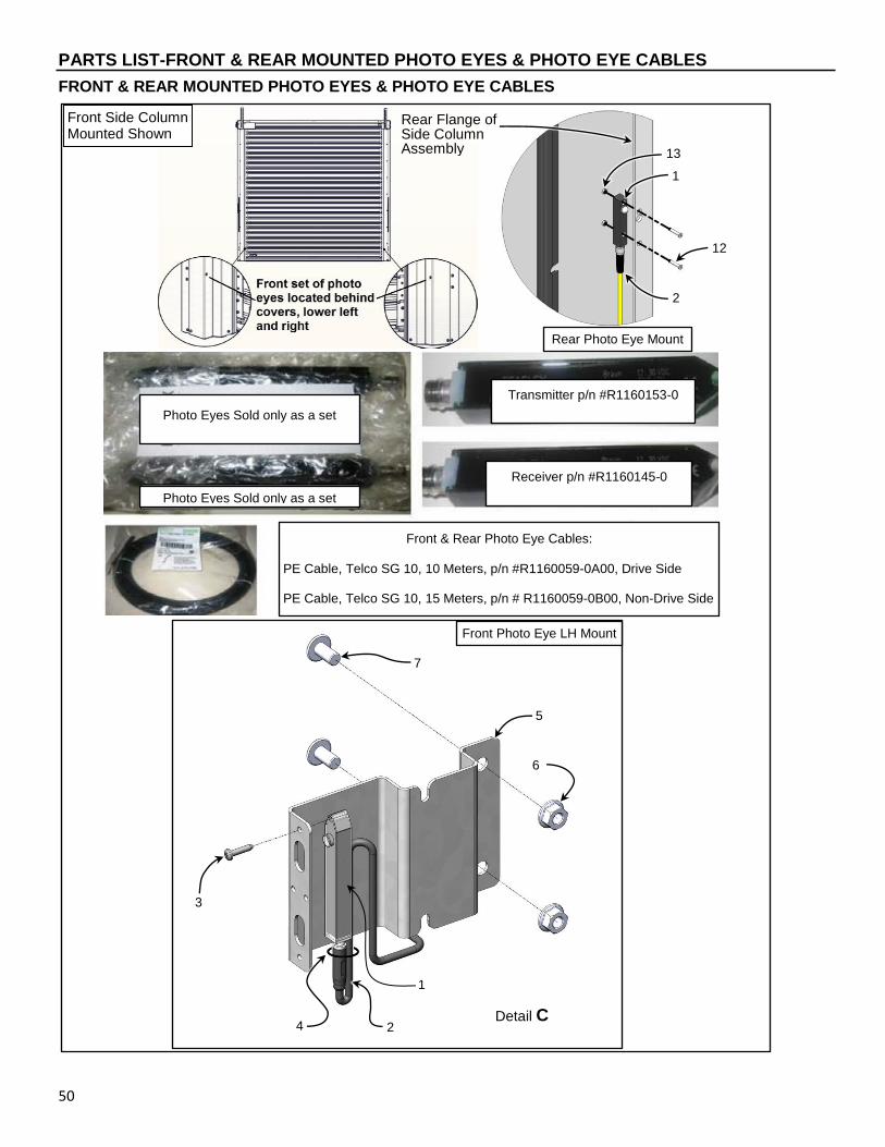
PARTS LIST-FRONT & REAR MOUNTED PHOTO EYES & PHOTO EYE CABLES
50
FRONT & REAR MOUNTED PHOTO EYES & PHOTO EYE CABLES
1
4
3
6
5
7
2
Front Side Column Mounted Shown
Front Photo Eye LH Mount
1
12
2
13
Rear Photo Eye Mount
Rear Flange of Side Column Assembly
Transmitter p/n #R1160153-0
Receiver p/n #R1160145-0
Photo Eyes Sold only as a set
Front & Rear Photo Eye Cables: PE Cable, Telco SG 10, 10 Meters, p/n #R1160059-0A00, Drive Side PE Cable, Telco SG 10, 15 Meters, p/n # R1160059-0B00, Non-Drive Side
Photo Eyes Sold only as a set
Detail C

PARTS LIST-FRONT & REAR MOUNTED PHOTO EYES & PHOTO EYE CABLES BOM
51
FRONT & REAR MOUNTED PHOTO EYES & PHOTO EYE CABLES BOM
ITEM QTY. PART # DESCRIPTION
- REF
R1071309-1X Assembly, Side Column, STT-L, SST-L/R, LH
R1071310-1X Assembly, Side Column, STT-S, LH
R1071311-1X Assembly, Side Column, SST-S/R, LH
R1071309-2X Assembly, Side Column, STT-L, SST-L/R, RH
R1071310-2X Assembly, Side Column, STT-S, RH
R1071311-2X Assembly, Side Column, SST-S/R, RH
1 1 each R1160153-0 Photo Eye, Transmitter, Telco SMT
R1160145-0 Photo Eye, Receiver, Telco SMR
2 1 each R1160059-0A00 Photo Eye Cable, Telco SG 10, 10M (Drive Side)
R1160059-0B00 Photo Eye Cable, Telco SG 10, 15M (Non-Drive Side)
3 2 R0550235 Screw, #6-32 UNC x 5/8 Pan Head Self Tapping
4 1 RN000046 Ties, Lock 5-5/8”
5 1 R1071415-0Z01 Bracket, Photo Eye Front
6 2 R01901508 Nut, M8 Flanged
7 2 R01900820 BSCFS,M8-1.25 x 20, T40, ZN
8
9
10
11
12 2 R5550068-0Z04 FSCS, M3-0.5 x 16, SS
13 2 R5550069-0Z04 Nut, M3-0.5, SS
CF = Consult Factory
A/R = As Required
Items are produced based on manufactured height and width of door.
ALWAYS INCLUDE SERIAL NUMBER OF DOOR WHEN PLACING ORDER Due to product enhancement, the actual parts on your door may be different from those shown in this manual.

PARTS LIST-STRAPS & BELTS (STT-L & S)
52
STRAPS & BELTS (STT-L & S)
STRAPS & BELTS (STT-L & S) BOM
ITEM QTY. PART # DESCRIPTION
1 REF R1210580-0 Secondary Tooth Belt, 1-1/4” “L” & “L/R” Size HTB
2 REF R1210581-0 Secondary Tooth Belt, 2” “S” & “S/R” Size HTB
3 REF R217603 Spring Belt, Poly 40mm Wide
4 REF R08310426 Drive Belt, “L” Size HTD
5 REF R083104261 Drive Belt, “S” Size HTD
6 REF R210865Z1 Assembly, Guide Pulley, Single
R238863Z1 Assembly, Guide Pulley, Double
7 A/R R01260140 HHCS, M6 x 20, DIN 933-8.8 ZN
8 A/R R205082Z1 Clamp Plate, Spring Belt
9 A/R R01270040 Nut, M6-1.0, Hex, DIN 934-8 ZN
10 A/R R01900708 BSCSF, M6 x 8, T30, ZN CF = Consult Factory A/R = As Required
ALWAYS INCLUDE SERIAL NUMBER OF DOOR WHEN PLACING ORDER Due to product enhancement, the actual parts on your door may be different from those shown in this manual.
SECONDARY DRIVE BELT (Black poly belt located in the side column, 2 sizes, please provide door serial number to determine length when ordering.)
SPRING BELT (STT L & S) (Blue belt in side columns, all Spiral Model doors use same blue spring belt, please provide door serial number to determine length when ordering.)
1
4
3
5
2
PRIMARY DRIVE BELT (STT L & S, SST-L & S), Belt from motor to drive shaft.
3
Drive Shaft Pulley
Motor Drive Shaft Pulley
Primary Drive Belt
7 8
9 10
6

PARTS LIST-PULLEYS, SPIRAL (STT-L & S, SST-L & S)
53
PULLEYS, SPIRAL (STT-L & S, SST-L & S)
PULLEYS, SPIRAL (STT-L & S, SST-L/R & S/R) BOM
ITEM QTY. PART # DESCRIPTION
1 1 R237804Z4 Pulley Assembly, Tooth Belt, L Size 1 ½” Wide
R238803Z4 Pulley Assembly, Tooth Belt, S Size 2 ½” Wide
2 1 R205533 Pulley, Upper Secondary Drive Belt, L Size
R206513X Pulley, Upper Secondary Drive Belt, S Size
3 A/R R1210580-0 Secondary Tooth Belt, 1-1/4” “L” & “L/R” Size HTB
R1210581-0 Secondary Tooth Belt, 2” “S” & “S/R” Size HTB
4 2 R01260286 HHCS, M8-1.25 x 40, DIN 933-8.8 ZN
5 4 R01270050 Nut,M8-1.25, Hex, DIN 934-8 ZN
CF = Consult Factory
A/R = As Required
ALWAYS INCLUDE SERIAL NUMBER OF DOOR WHEN PLACING ORDER Due to product enhancement, the actual parts on your door may be different from those shown in this manual.
“L” Series Pulley Shown
LOWER PULLEY – STT-L & S (Lower pulley’s have 2 sizes depending on door model, please provide door serial number when ordering.)
1 2
1
3
4
5

PARTS LIST-SINGLE SPRING PACK (STT-L & S, SST-L & S) ASSEMBLY
54
SINGLE SPRING PACK (STT-L & S, SST-L & S) ASSEMBLY
8
3
2 4
1
5
6
7
7
9

PARTS LIST-SINGLE SPRING PACK (STT-L & S, SST-L & S) ASSEMBLY BOM
55
SINGLE SPRING PACK (STT-L & S, SST-L & S) ASSEMBLY BOM
ITEM QTY. PART # DESCRIPTION
- 1 R217871B02Z1 Spring Pack Assembly (1 Outside)
1 1 REF Screw, M10 x 30 Hex Head, DIN 933 8.8
2 1 R609270BZ1 Shoulder Nut, Special Spring Clevis
3 1 R01260400 Screw, M12 x 20 Hex Head, DIN 933
4 1 R01060044 Washer, 13 mm Flat, ZN
5 1 REF Clevis, Spring Pack
6 1 REF Guide, Outer Spring Pack, 1 or 2
7 2 REF Spring, Plug
8 1 REF Tension Spring
9 1 REF Assembly, Spring Pack Adjustment Rod
CF = Consult Factory
A/R = As Required
*Installed Only on Door’s Drive Side Side Columns.
Items are produced based on manufactured height and width of door.
ALWAYS INCLUDE SERIAL NUMBER OF DOOR WHEN PLACING ORDER
Due to product enhancement, the actual parts on your door may be different from those shown in this manual.

PARTS LIST-DOUBLE SPRING PACK (STT-L & S, SST-L & S) ASSEMBLY
56
DOUBLE SPRING PACK (STT-L & S, SST-L & S) ASSEMBLY
1
2
3 4
7
6
7
10
11
8
6
1
1 1
1
5
8
9
12
14
10
13
(INSIDE SPRING PACK ASSEMBLY ONLY)

PARTS LIST-DOUBLE SPRING PACK (STT-L & S, SST-L & S) ASSEMBLY BOM
57
DOUBLE SPRING PACK (STT-L & S, SST-L & S) ASSEMBLY BOM
ITEM QTY. PART # DESCRIPTION
- 1
R217871A03Z1 Spring Pack Assembly (2 Outside)
R217871A03Z1 Spring Pack Assembly (2 Outside) “L” Series
R217871DZ1 Spring Pack Assembly (2 Inside)
1 5 REF Screw, M10 x 30 Hex Head, DIN 933 8.8
2 1 R609270BZ1 Shoulder Nut, Special Spring Clevis
3 1 R01260400 Screw, M12 x 20 Hex Head, DIN 933
4 1 R01060044 Washer, 13 mm Flat, ZN
5 1 REF Clevis, Spring Pack
6 2 REF Bar, 2 Spring Pack
7 2 REF Guide Outer Spring Pack, Hard PVC (Outside Spring Pack Assembly only)
8 4 REF Spring, Plug
9 2 REF Tension Spring
10 1
REF Guide Bracket Assembly, Outer Dual Spring (L Series)
REF Guide Bracket Assembly, Outer Dual Spring
REF Guide Bracket Assembly, Inside Dual Spring
11 2 REF Guide Tube, Spring Pack Hard PVC
12 1 REF Assembly, Spring Pack Adjustment Rod
13 2 REF Nut, M6 Hex Flange (Inside Spring Pack Assembly only)
14 2 REF Screw, M6 x 14 mm Hex Head Cap, Zn (Inside Spring Pack Assembly only)
CF = Consult Factory
A/R = As Required
*Installed Only on Door’s Drive Side Side Columns.
Items are produced based on manufactured height and width of door.
ALWAYS INCLUDE SERIAL NUMBER OF DOOR WHEN PLACING ORDER
Due to product enhancement, the actual parts on your door may be different from those shown in this manual.
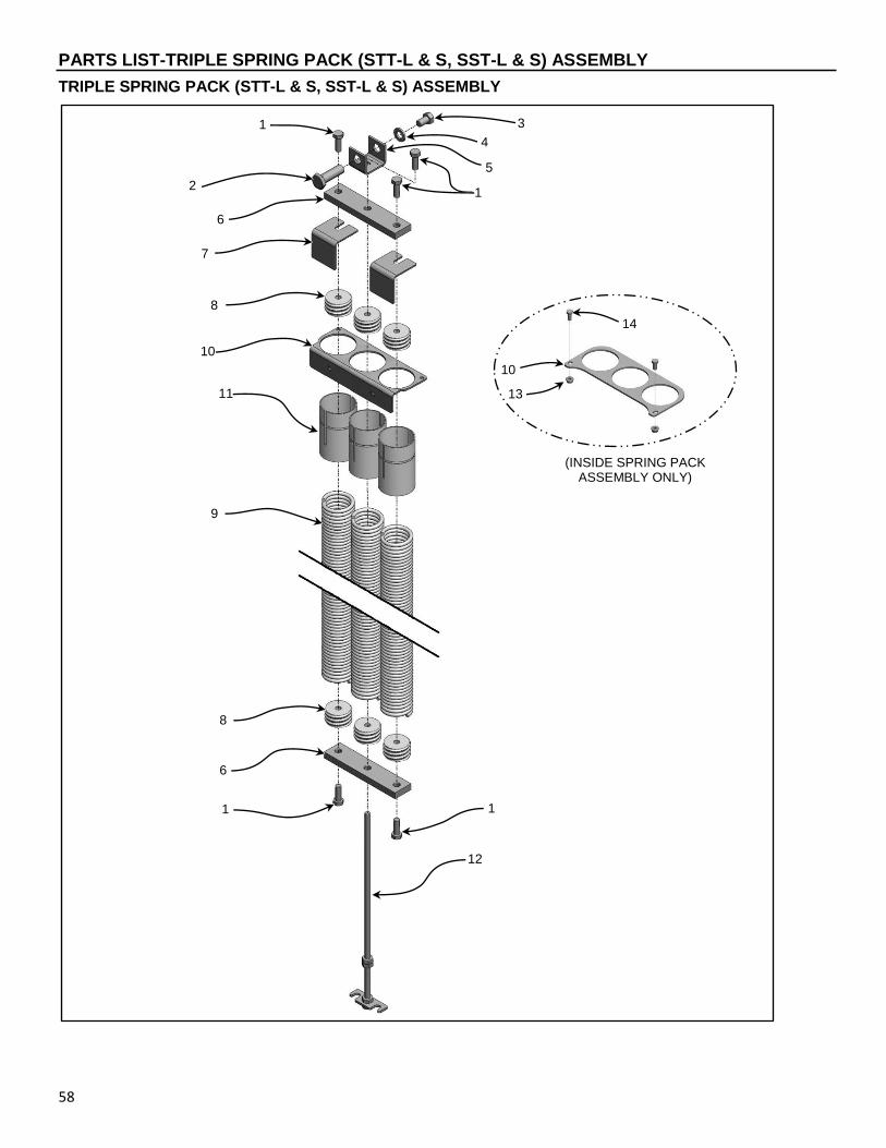
PARTS LIST-TRIPLE SPRING PACK (STT-L & S, SST-L & S) ASSEMBLY
58
TRIPLE SPRING PACK (STT-L & S, SST-L & S) ASSEMBLY
12
5
1
6
8
9
11
10
8
7
6
2
3
4
1
14
10
13
(INSIDE SPRING PACK ASSEMBLY ONLY)
1
.
1

PARTS LIST-TRIPLE SPRING PACK (STT-L & S, SST-L & S) ASSEMBLY BOM
59
TRIPLE SPRING PACK (STT-L & S, SST-L & S) ASSEMBLY BOM
ITEM QTY. PART # DESCRIPTION
- 1 R217871C03Z1 Spring Pack Assembly (3 Outside)
R217871EZ1 Spring Pack Assembly (3 Inside)
1 5 REF Screw, M10 x 30 Hex Head, DIN 933 8.8
2 1 R609270BZ1 Shoulder Nut, Special Spring Clevis
3 1 R01260400 Screw, M12 x 20 Hex Head, DIN 933
4 1 R01060044 Washer, 13 mm Flat, ZN
5 1 REF Clevis, Spring Pack
6 2 REF Bar, 3 Spring Pack
7 2 REF Guide Outer Spring Pack, Hard PVC (Outside Spring Pack Assembly only)
8 6 REF Spring, Plug
9 3 REF Tension Spring
10 1
REF Guide Bracket Assembly, Outer Triple Spring
REF Guide Bracket Assembly, Inside Triple Spring (Inside Spring Pack Assembly only)
11 3 REF Guide Tube, Spring Pack Hard PVC
12 1 REF Assembly, Spring Pack Adjustment Rod
13 2 REF Nut, M6 Hex Flange (Inside Spring Pack Assembly only)
14 2 REF Screw, M6 x 14 mm Hex Head Cap, Zn (Inside Spring Pack Assembly only)
CF = Consult Factory
A/R = As Required
*Installed Only on Door’s Drive Side Side Columns.
Items are produced based on manufactured height and width of door.
ALWAYS INCLUDE SERIAL NUMBER OF DOOR WHEN PLACING ORDER
Due to product enhancement, the actual parts on your door may be different from those shown in this manual.
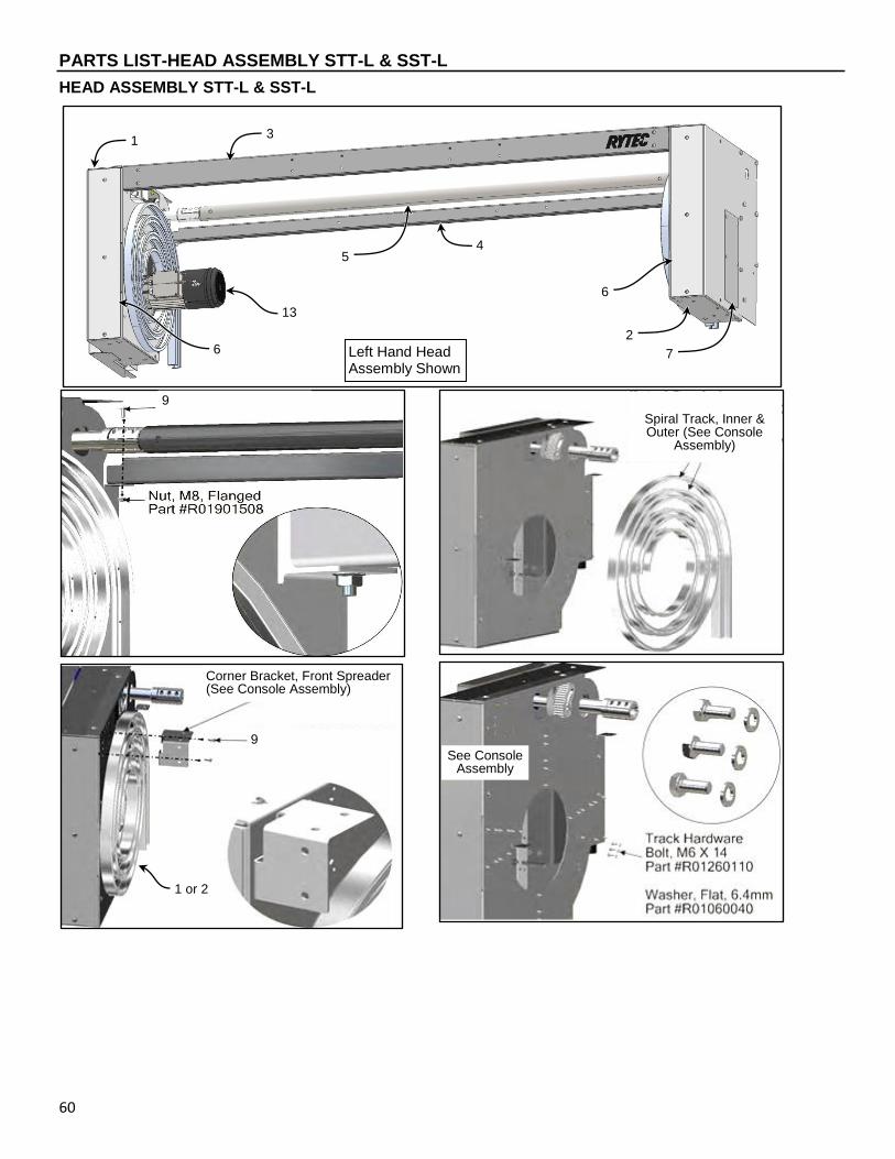
PARTS LIST-HEAD ASSEMBLY STT-L & SST-L
60
HEAD ASSEMBLY STT-L & SST-L
Left Hand Head Assembly Shown
1 or 2
6
4
2
1 3
7
6
5
Corner Bracket, Front Spreader (See Console Assembly)
9
9
Spiral Track, Inner & Outer (See Console
Assembly)
13
See Console Assembly
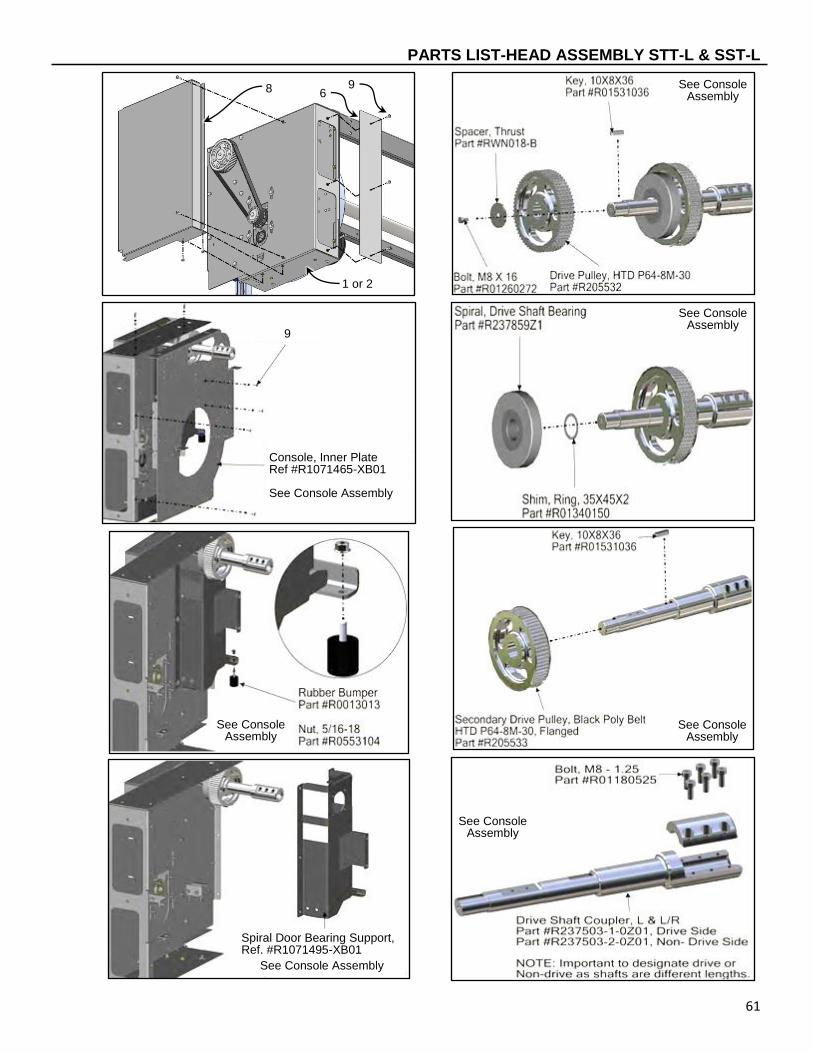
PARTS LIST-HEAD ASSEMBLY STT-L & SST-L
61
6 8
1 or 2
9
See Console Assembly
See Console Assembly
Console, Inner Plate Ref #R1071465-XB01 See Console Assembly
See Console Assembly
See Console Assembly
See Console Assembly
Spiral Door Bearing Support, Ref. #R1071495-XB01
See Console Assembly
9

PARTS LIST-HEAD ASSEMBLY STT-L & SST-L BOM
62
HEAD ASSEMBLY STT-L & SST-L BOM
ITEM QTY. PART # DESCRIPTION
- 1 CF Assembly, Head, STT-L & SST-L, LH Motor Mount
Assembly, Head, STT-L & SST-L, RH Motor Mount
1 1 CF Console Assembly, STT-L & SST-L, LH, LH Motor Mount
Console Assembly, STT-L & SST-L, LH, RH Motor Mount
2 1 CF Console Assembly, STT-L & SST-L, RH, LH Motor Mount
Console Assembly, STT-L & SST-L, RH, RH Motor Mount
3 1 CF Front Spreader, STT-L & SST-L
4 1 CF Rear Spreader, STT-L & SST-L
5 1 R217706Z1 Drive Shaft, “L” Series
6 2*
R1071544-0B01 Cover, Console Front, STT-L & SST-L, B-Head
7 1 CF Cover, Console Non-Drive Side
8 1 R1071482-XB02 Belt Guard, STT-L & SST-L, LH
Belt Guard, STT-L & SST-L, RH
9 A/R R01900820 BSCSF,M8-1.25 X 16,T40,ZN
10 A/R R01260310 HHCS, M10 x 20, Din 933-8.8 ZN
11 A/R R01060043 Washer, 10.5mm Flat, DIN 125A ZN
12 1 R231833 Seal Assembly, Spiral Door Rear Horizontal, STT
R237867Z4 Seal Assembly, Spiral Door Rear Horizontal, SST
13 1* CF Motor Assembly, Complete
CF = Consult Factory
A/R = As Required
* = Part of the Console Assembly
Items are produced based on manufactured height and width of door.
ALWAYS INCLUDE SERIAL NUMBER OF DOOR WHEN PLACING ORDER Due to product enhancement, the actual parts on your door may be different from those shown in this manual.
10
11
12
9

NOTES
63
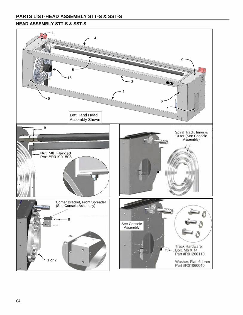
PARTS LIST-HEAD ASSEMBLY STT-S & SST-S
64
HEAD ASSEMBLY STT-S & SST-S
1 or 2
Corner Bracket, Front Spreader (See Console Assembly)
9
9
Spiral Track, Inner & Outer (See Console
Assembly)
See Console Assembly
Left Hand Head Assembly Shown
6
3
7
1
4
6
5
13
2
3

PARTS LIST-HEAD ASSEMBLY STT-S & SST-S
65
See Console Assembly
Bracket, Console Wall Mount #R1071543-0Z1
6
8
1 or 2
9
See Console Assembly
9
Console, Inner Insert, LH Ref #R1071471-1D01 Console, Inner Insert, RH Ref #R1071471-2D01
See Console Assembly
See Console Assembly
See Console Assembly
See Console Assembly
Support Bearing Insert, LH Ref #R1071477-1D01 Support Bearing Insert, RH Ref #R1071477-2D01
Washer, 8mm, Lock #R01080030
Spacer, Thrust #RWN018-B
Bolt, M8 x 16, #R01260272

PARTS LIST-HEAD ASSEMBLY STT-S & SST-S
66
See Console Assembly
14
15
16
See Console Assembly
9
9
10
11 12
8

PARTS LIST-HEAD ASSEMBLY STT-S & SST-S BOM
67
HEAD ASSEMBLY STT-S & SST-S BOM
ITEM QTY. PART # DESCRIPTION
- 1 CF Assembly, Head, STT-S & SST-S, LH Motor Mount
Assembly, Head, STT-S & SST-S, RH Motor Mount
1 1 CF Console Assembly, STT-S & SST-S, LH, LH Motor Mount
Console Assembly, STT-S & SST-S, LH, RH Motor Mount
2 1 CF Console Assembly, STT-S & SST-S, RH, LH Motor Mount
Console Assembly, STT-S & SST-S, RH, RH Motor Mount
3 2 CF Front Spreader, STT-S & SST-S & S/R
4 1 CF Rear Spreader, STT-S & SST-S & S/R
5 1 R218704Z1 Drive Shaft, “S” Series
6 2*
R1071545-0D01 Cover, Console Front, STT-S & SST-S, D-Head
7 1 CF Cover, Console Non-Drive Side
8 1 R1071482-1D01 Belt Guard, STT-S & SST-S, LH
R1071482-2D01 Belt Guard, STT-S & SST-S, RH
9 A/R R01900820 BSCSF,M8-1.25 X 16,T40,ZN
10 A/R R01260310 HHCS, M10 x 20, Din 933-8.8 ZN
11 A/R R01060043 Washer, 10.5mm Flat, DIN 125A ZN
12 1 R231833 Seal Assembly, Spiral Door Rear Horizontal, STT
R237867Z4 Seal Assembly, Spiral Door Rear Horizontal, SST
13 1* CF Motor Assembly, Complete
14 4 R01260320 HHCS, M10 x 25, DIN 933.8-8 ZN
15 4 R01800080 Washer, 10.5 x 25, DIN 9021A ZN
16 1 R1070419-0 Edge Protector, 161.08mm
CF = Consult Factory
A/R = As Required
Items are produced based on manufactured height and width of door.
ALWAYS INCLUDE SERIAL NUMBER OF DOOR WHEN PLACING ORDER
Due to product enhancement, the actual parts on your door may be different from those shown in this manual.
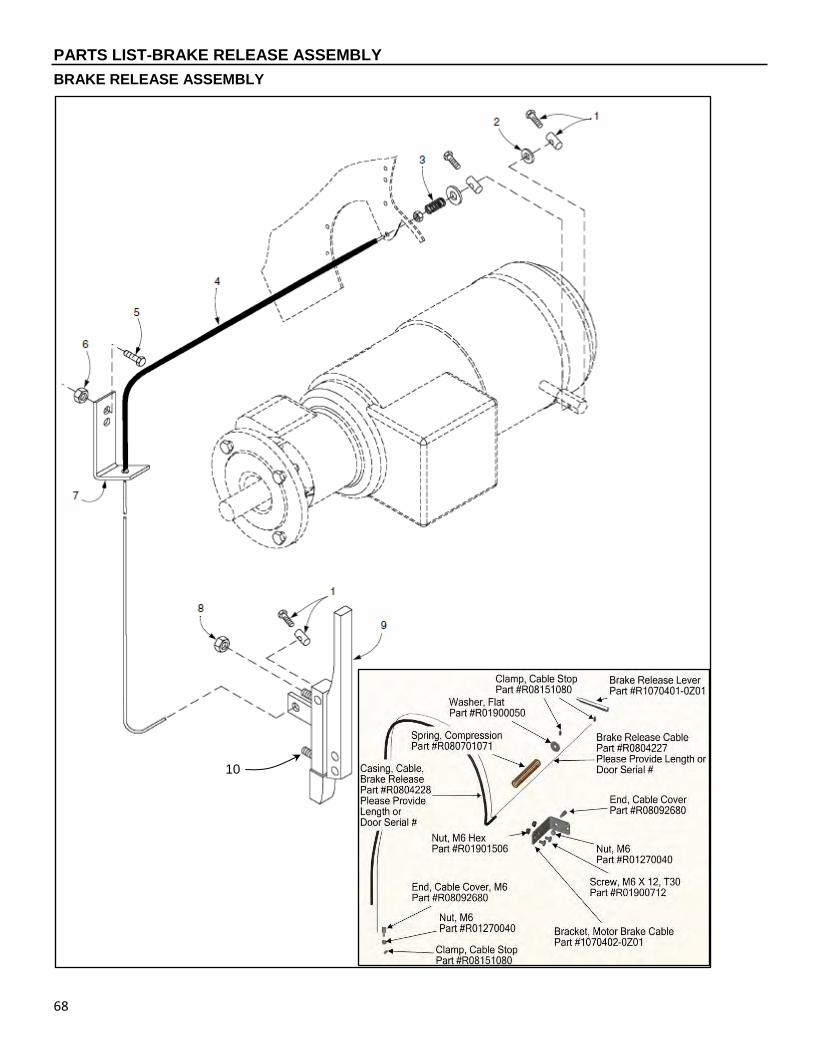
PARTS LIST-BRAKE RELEASE ASSEMBLY
68
BRAKE RELEASE ASSEMBLY
10
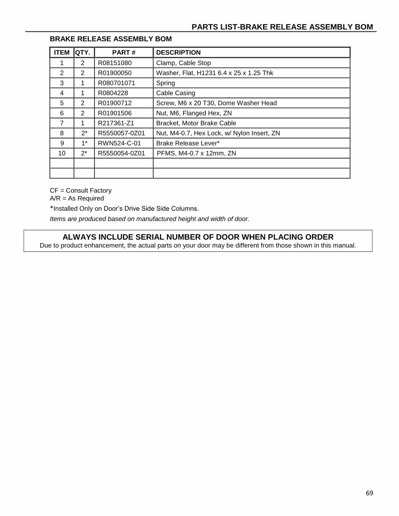
PARTS LIST-BRAKE RELEASE ASSEMBLY BOM
69
BRAKE RELEASE ASSEMBLY BOM
ITEM QTY. PART # DESCRIPTION
1 2 R08151080 Clamp, Cable Stop
2 2 R01900050 Washer, Flat, H1231 6.4 x 25 x 1.25 Thk
3 1 R080701071 Spring
4 1 R0804228 Cable Casing
5 2 R01900712 Screw, M6 x 20 T30, Dome Washer Head
6 2 R01901506 Nut, M6, Flanged Hex, ZN
7 1 R217361-Z1 Bracket, Motor Brake Cable
8 2* R5550057-0Z01 Nut, M4-0.7, Hex Lock, w/ Nylon Insert, ZN
9 1* RWN524-C-01 Brake Release Lever*
10 2* R5550054-0Z01 PFMS, M4-0.7 x 12mm, ZN
CF = Consult Factory
A/R = As Required
*Installed Only on Door’s Drive Side Side Columns.
Items are produced based on manufactured height and width of door.
ALWAYS INCLUDE SERIAL NUMBER OF DOOR WHEN PLACING ORDER
Due to product enhancement, the actual parts on your door may be different from those shown in this manual.
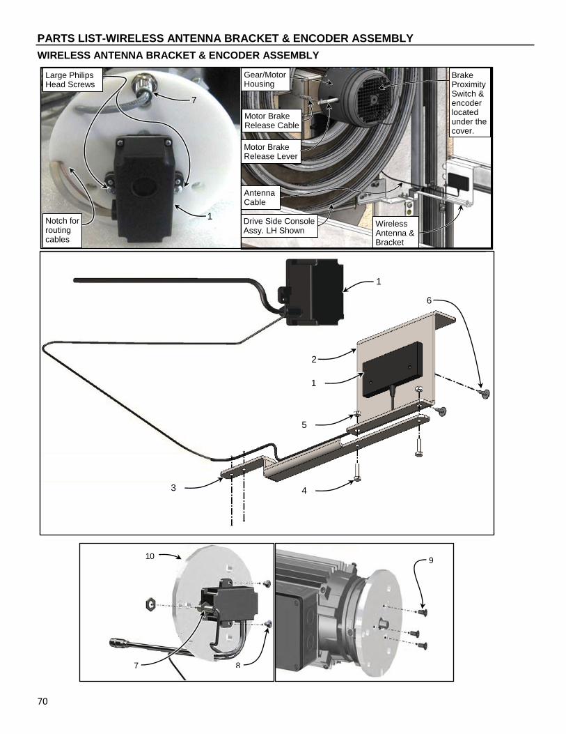
PARTS LIST-WIRELESS ANTENNA BRACKET & ENCODER ASSEMBLY
70
WIRELESS ANTENNA BRACKET & ENCODER ASSEMBLY
3
Large Philips Head Screws
Notch for routing cables
2
1
5
4
1
6
1
7
9 10
7 8
Antenna Cable
Drive Side Console Assy. LH Shown
Motor Brake Release Lever
Wireless Antenna & Bracket
Brake Proximity Switch & encoder located under the cover.
Motor Brake Release Cable
Gear/Motor Housing

PARTS LIST-WIRELESS ANTENNA BRACKET & ENCODER ASSEMBLY BOM
71
WIRELESS ANTENNA BRACKET & ENCODER ASSEMBLY BOM
ITEM QTY. PART # DESCRIPTION
1 1 R00141120 Wireless Encoder w/ Antenna, XR 60” Spiral
2 1 R1070678-0Z01 Bracket, Wireless Antenna Mounting, Spiral
R1070699-2Z01 Corner Bracket, Upper RH Wireless L & L/S size
3 1 R1070960-0Z01 Bracket, Upper Corner Wireless Arm
4 2 R5550246-0Z01 HHCS, M4-0.7 x 16, Gr 5 ZN
5 2 R5550057-0Z01 Nut, M4-0.7, Hex Lock, w/ Nylon Insert, ZN
6 2 R5550264-0 Ratchet Fastener, 0.160 Hole x 0.040-0.250 Thk, Black Nylon
7 1 R00111188 Inductive Sensor, M12x1.0, 4.0mm Gap, 10-30 DVC
8 REF R0550317 Screw, #10-24 x ½”, Phil Truss HD
9 REF R01750080 FHSCS, M6 x 16, DIN 7991 12.9
10 REF R1070144-0 Encoder Mounting Plate
CF = Consult Factory
A/R = As Required
*Installed Only on Door’s Drive Side Side Columns.
Items are produced based on manufactured height and width of door.
ALWAYS INCLUDE SERIAL NUMBER OF DOOR WHEN PLACING ORDER Due to product enhancement, the actual parts on your door may be different from those shown in this manual.

PARTS LIST-SPREADER AND DOOR PANEL ASSEMBLY
72
SPREADER AND DOOR PANEL ASSEMBLY
Detail “A” (NON-WIRELESS ONLY)
Also See Detail “A” (NON-WIRELESS ONLY)
10
1
2
33
3
4
20
5
19
6
7
8
9
.
11
12
13
14
15
16
17
18
21
14
22
23
23
24
31 32
26
27
28
29
30
34
35
36
37
24

PARTS LIST-SPREADER AND DOOR PANEL ASSEMBLY BOM
73
SPREADER AND DOOR PANEL ASSEMBLY BOM
CF = Consult Factory
A/R = As Required
*Items are produced based on manufactured height
and width of door.
ITEM QTY. PART # DESCRIPTION
18 A/R REF
R231114 Hinge, Aluminum, Window-Vent, 151x65 (Included in Items 7 & 8)
R232100 Hinge, Aluminum, Window-Vent, 151x100 (Included in Items 7 & 8)
R231117 Hinge, Aluminum, Window-Vent, 225x65 (Included in Items 7 & 8)
19 A/R REF
R217502-02 AXLE, HINGE, 98mm (Included in Items 7 & 8)
R218504 AXLE, HINGE, 133mm (Included in Items 7 & 8)
20 2
REF
R237506 AXLE, HINGE, Top, 99mm (Included in Items 7 & 8)
R238506 AXLE, HINGE, Top, 134mm (Included in Items 7 & 8)
21 4
R01160515 Screw, Mushroom Head Square Neck M8x45 (STT-L)
R01160505 Screw, Mushroom Head Square Neck M8x35 (SST-L)
R01160605 Screw, Mushroom Head Square Neck M10x50 (STT-S)
R01160600 Screw, Mushroom Head Square Neck M10x40 (SST-S)
22 4 R01230008 Nut, M8 Hex Cap
R01230010 Nut, M10-1.5 Hex Cap
23 2 R01915015 Label, Window Wipe Down Caution
24 4 R0550235 Screw, #6-32UNCx5/8 PH Tapping
25
26 1 CF End Bracket Assembly, STT-L, SST-L, STT-S, SST-S, LH
27 1 CF End Bracket Assembly, STT-L, SST-L, STT-S, SST-S, RH
28 A/R R01900705 BSCSF, M5 x 20 T25 Torx Drive (Window-Vent Hinges)
29 1 R1070776-X Reversing Edge Assembly, LH/RH
30 REF CF Rear Spreader
31 1 R1060514-0 Cover Assembly, Spiral Mobile Unit
32 1 R1070625-0 Gasket, Wireless Cover
33 1 R1070777-0 Assembly, Energy Chain Clamp (Non-Wireless Only)
34 1 R01010152 Screw, M4 x 16 SCMS (Non-Wireless)
35 1 R00111174 Block, Terminal (Non-Wireless only)
36 3 R02382756 Wire Clip (Non-Wireless only)
37 5 R01010125 Screw, SCMS M4 x 6 mm (Non-Wireless only)
ITEM QTY. PART # DESCRIPTION
- 1 CF Panel/Hinge Assembly, SST-L & STT-L
CF Panel/Hinge Assembly, SST-S & STT-S
1 REF CF Top Seal (Included in Rear Seal)
2 1 CF Assy, Top Panel, STT-L, SST-L
CF Assy, Top Panel, STT-S, SST-S
3 A/R R237602 Guide Roller, Slide Door Panel
4 A/R R217505Z1 Spacer, Axle
5 A/R R205625 Roller, Hinge
6 A/R R01335008 Nut, Lock, DIN 985-8 M8 Nylon Insert Hex
7 1
CF Hinge, Chain Assembly, SST-L & STT-L, LH
CF Hinge, Chain Assembly, SST-S & STT-S, LH
8 1
CF Hinge, Chain Assembly, SST-L & STT-L, RH
CF Hinge, Chain Assembly, SST-S & STT-S, RH
9 A/R REF
R1070525 Pin, Groove (Included in Items 7 & 8)
10 A/R R04010085-04 Seal, Panel Hinge
11 A/R CF Panel Assembly, STT-L, SST-L
CF Panel Assembly, STT-S, SST-S
12
A/R
CF Window Assembly, SST-S, SST-L, STT-S, STT-L, SSN-S, SSN-L
CF Window Assembly, SST-S, SST-L, STT-S, STT-L, SSN-S, SSN-L
A/R
CF Vent Assembly, SST-S, SST-L, STT-S, STT-L, SSN-S, SSN-L
CF Vent Assembly, SST-S, SST-L, STT-S, STT-L, SSN-S, SSN-L
13 1
CF Bottom Panel Assembly, STT-L & SST-L
CF Bottom Panel Assembly, STT-S & SST-S
14 A/R R01900720 BSCSF, M6 x 20 T30 Torx Drive
15 A/R REF
R231110 Hinge, Aluminum, Bottom, 151x65 (Included in Items 7 & 8)
R232102 Hinge, Aluminum, Bottom, 151x100 (Included in Items 7 & 8)
R1070993-0 Hinge, Aluminum, Middle, 151x65 (Included in Items 7 & 8)
16 A/R REF
R231120 Hinge, Aluminum, Middle, 151x65 (Included in Items 7 & 8)
R232111 Hinge, Aluminum, Middle, 151x100 (Included in Items 7 & 8)
17 A/R REF
R231111 Hinge, Aluminum, Top, 151x65 (Included in Items 7 & 8)
R232101 Hinge, Aluminum, Top, 151x100 (Included in Items 7 & 8)
ALWAYS INCLUDE SERIAL NUMBER OF DOOR WHEN PLACING ORDER Due to product enhancement, the actual parts on your door may be different from those shown in this manual.

PARTS LIST-DOOR PANEL BOTTOM BAR END BRACKET ASSEMBLIES
74
DOOR PANEL BOTTOM BAR END BRACKET ASSEMBLIES
#R231831-1X SHOWN (#R231831-2X IS OPPOSITE HAND)
#R1071000-1 SHOWN (#R1071000-2 IS OPPOSITE HAND)
1
2
4
3 6
5
7
8
8
5
4
1 2
3
6
7
Sold Only as
an Assembly
Sold Only as
an Assembly

PARTS LIST-DOOR PANEL BOTTOM BAR END BRACKET ASSEMBLY BOMS
75
DOOR PANEL BOTTOM BAR END BRACKET ASSEMBLY BOMS
ITEM QTY. PART # DESCRIPTION
- 1 R231831-1 End Bracket Assembly, STT-L, LH (231831-2 is opposite hand)
R237831-1 End Bracket Assembly, SST-L, LH (237831-2 is opposite hand)
1 1 CF End Plate, End Bracket, SST-L, LH
2 1 CF Splice Block, End Bracket, 8M-30mm
3 1 CF Splice Clamp, End Bracket, 8M-30mm
4 2 CF Spacer Bushing, End Bracket, 10mm
5 2 CF HHCS, M10-1.50 x 30, DIN 933-8.8, ZN
6 2 CF HHCS, M10-1.50 x 65, DIN 933-8.8, ZN
7 2 CF Nut, M10-1.50, Nylon Lock DIN 985-8
8 A/R CF Spacer Plate, End Bracket, 30mm
End Brackets Sold as Complete Assemblies only
- 1 R1071000-1 End Bracket Assembly, STT-S, LH (R1071000-2 is opposite hand)
R238831-1 End Bracket Assembly, SST-S, LH (238831-2 is opposite hand)
1 1 CF End Plate, End Bracket, STT-S, LH
2 1 CF Splice Block, End Bracket, 8M-50mm
3 1 CF Splice Clamp, End Bracket, 8M-50mm
4 2 CF Spacer Bushing, End Bracket, 17mm
5 2 CF HHCS, M10-1.50 x 30, DIN 933-8.8, ZN
6 2 CF HHCS, M10-1.50 x 65, DIN 933-8.8, ZN
7 2 CF Nut, M8, Nylon Lock
8 A/R CF Spacer Plate, End Bracket, 10mm
CF = Consult Factory
A/R = As Required
Items are produced based on manufactured height and width of door.
ALWAYS INCLUDE SERIAL NUMBER OF DOOR WHEN PLACING ORDER Due to product enhancement, the actual parts on your door may be different from those shown in this manual.

PARTS LIST-REVERSING EDGE – WIRELESS
76
REVERSING EDGE – WIRELESS
REMINDER: When replacing the mobile unit the new mobile unit address number MUST be entered into parameter P:F07 for the wireless reversing edge to operate. In the example above P:F07 must be set to B359. NOTE: Mobile unit address is in hexadecimal numbers and therefore, could contain letters in the mobile unit address.
1
6
5
4
3
2
Bottom Bar Reversing Edge
(Consult Factory)

PARTS LIST-REVERSING EDGE – WIRELESS BOM
77
REVERSING EDGE – WIRELESS BOM
ITEM QTY. PART # DESCRIPTION
1 1 R1070625-1 Gasket, Wireless Cover
2 1 R00111193 Battery, Wireless “D” w/ Tabs
3 1 R1210463-0 Mobile Unit, Sealed Wireless Transmitter XL
4 1 R1060116-0 Wireless Cover
5 1 R1210110-0 Label, RY-WI Wireless Cover
6 2 R01900720 BSCSF, M5 x 20, T25 ZN
CF = Consult Factory
A/R = As Required
ALWAYS INCLUDE SERIAL NUMBER OF DOOR WHEN PLACING ORDER Due to product enhancement, the actual parts on your door may be different from those shown in this manual.
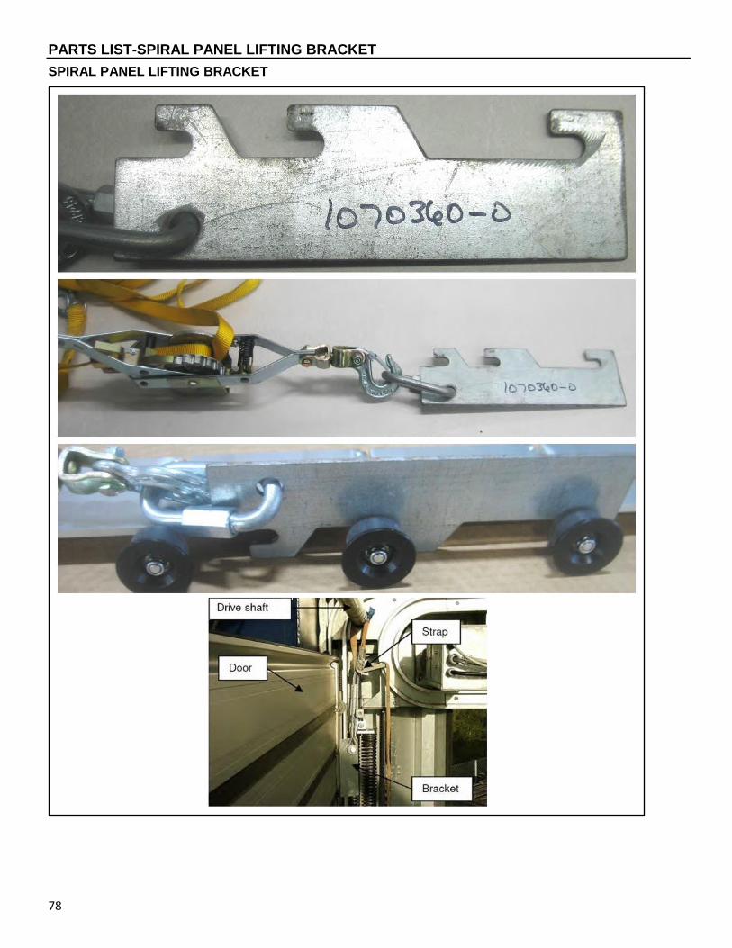
PARTS LIST-SPIRAL PANEL LIFTING BRACKET
78
SPIRAL PANEL LIFTING BRACKET

PARTS LIST-SPIRAL PANEL LIFTING BRACKET BOM
79
SPIRAL PANEL LIFTING BRACKET BOM
ITEM QTY. PART # DESCRIPTION
- 1 R1070360-0Z1 Plate, Door Panel Service, one bracket per side
CF = Consult Factory
A/R = As Required
ALWAYS INCLUDE SERIAL NUMBER OF DOOR WHEN PLACING ORDER Due to product enhancement, the actual parts on your door may be different from those shown in this manual.

NOTES
80

NOTES
81