Embed Size (px)
Citation preview
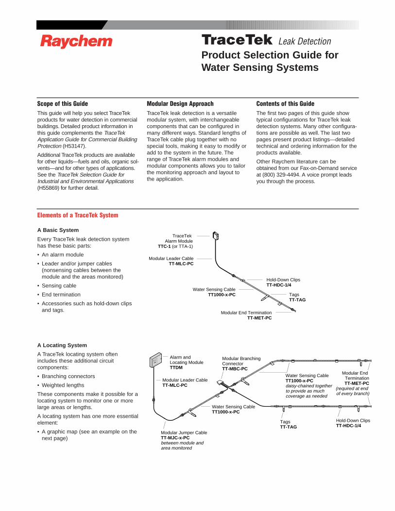
Scope of this GuideThis guide will help you select TraceTekproducts for water detection in commercialbuildings. Detailed product information inthis guide complements the TraceTekApplication Guide for Commercial BuildingProtection (H53147).
Additional TraceTek products are availablefor other liquids—fuels and oils, organic sol-vents—and for other types of applications.See the TraceTek Selection Guide forIndustrial and Environmental Applications(H55869) for further detail.
Modular Design ApproachTraceTek leak detection is a versatilemodular system, with interchangeablecomponents that can be configured inmany different ways. Standard lengths ofTraceTek cable plug together with nospecial tools, making it easy to modify oradd to the system in the future. Therange of TraceTek alarm modules andmodular components allows you to tailorthe monitoring approach and layout tothe application.
Contents of this GuideThe first two pages of this guide showtypical configurations for TraceTek leakdetection systems. Many other configura-tions are possible as well. The last twopages present product listings—detailedtechnical and ordering information for theproducts available.
Other Raychem literature can beobtained from our Fax-on-Demand serviceat (800) 329-4494. A voice prompt leadsyou through the process.
R TraceTek Leak DetectionProduct Selection Guide for Water Sensing Systems
Elements of a TraceTek System
A Basic System
Every TraceTek leak detection systemhas these basic parts:
• An alarm module
• Leader and/or jumper cables (nonsensing cables between the module and the areas monitored)
• Sensing cable
• End termination
• Accessories such as hold-down clipsand tags.
A Locating System
A TraceTek locating system oftenincludes these additional circuit components:
• Branching connectors
• Weighted lengths
These components make it possible for alocating system to monitor one or morelarge areas or lengths.
A locating system has one more essentialelement:
• A graphic map (see an example on thenext page)
TagsTT-TAG
Hold-Down ClipsTT-HDC-1/4
Water Sensing CableTT1000-x-PC
Modular Leader CableTT-MLC-PC
TraceTek Alarm Module
TTC-1 (or TTA-1)
Modular End TerminationTT-MET-PC
Modular Jumper CableTT-MJC-x-PCbetween module and area monitored
Modular Leader CableTT-MLC-PC
Water Sensing CableTT1000-x-PC
Alarm and Locating ModuleTTDM
Water Sensing CableTT1000-x-PCdaisy-chained togetherto provide as much coverage as needed
Modular BranchingConnectorTT-MBC-PC
TagsTT-TAG
Hold-Down ClipsTT-HDC-1/4
Modular End TerminationTT-MET-PC
(required at end of every branch)
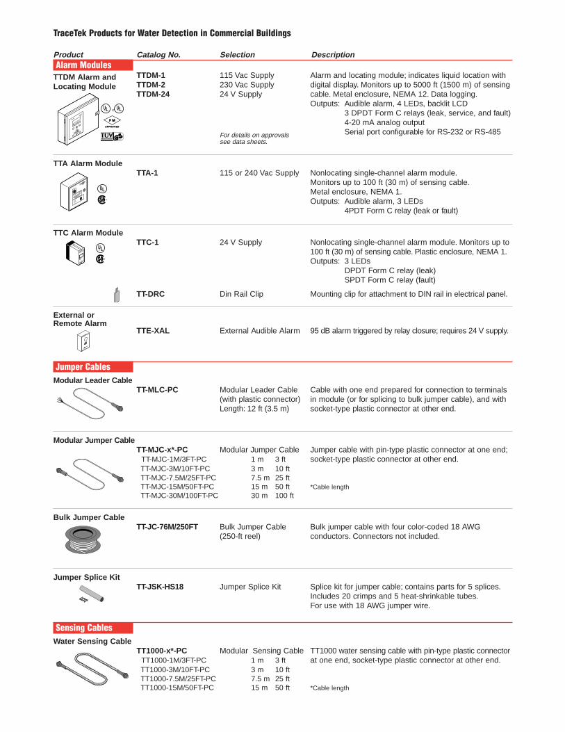
A TraceTek locating system can monitorone or more large areas. If water contactsthe sensing cable, the alarm and locatingmodule indicates the location with a digitaldisplay. A system map created after instal-lation provides reference points (e.g., in the illustration) to facilitate a quick,effective response.
shows where the sensing circuitjumps to a new room and a weightedlength is used. The weighted length simulates 15 ft of sensing cable so thesystem map will show a clear divisionbetween the separate areas.
shows a branch in the sensing circuit. ATraceTek branching connector is wired sothe connected branches appear in series,middle leg first. The branching connectoralso adds a simulated cable length of 15 fton each branch to make a clear divisionbetween areas. Although not shown, a system may have branches within branches.The number of branches is limited only bythe length of the sensing circuit.
BA
25
Modular jumper cables
Modularbranchingconnector
Modularendtermination
Modular end termination
Weighted LengthTT-WL-4.5M/15FT-PC
Bulk Jumper CableTT-JC
Jumper Splice KitTT-JSK-HS18
Modular leader cable
Watersensingcable
75
90
130
245
395
345
270
295
320
205
230
50
25
180
155115
1
B
Drawingnot to scale
Alarm and locating moduleTTDM
A
370
Wide Area Coverage: TraceTek Locating System
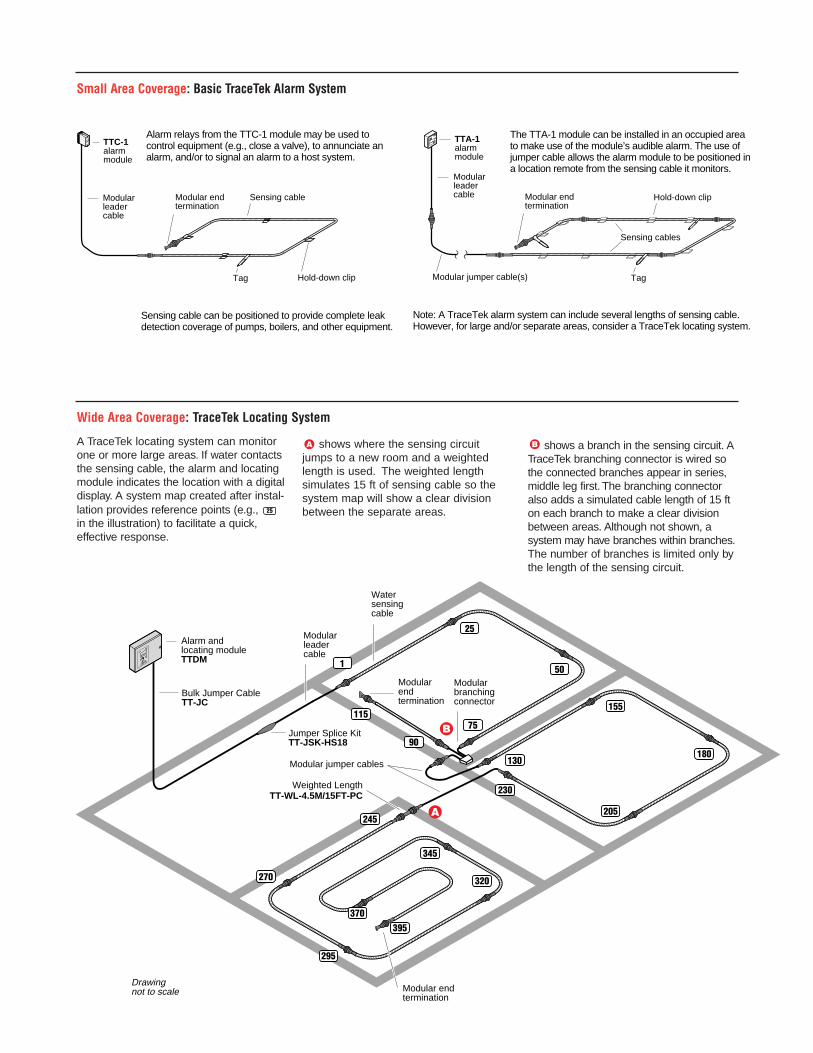
Note: A TraceTek alarm system can include several lengths of sensing cable. However, for large and/or separate areas, consider a TraceTek locating system.
Modular leader cable
Modular jumper cable(s)
Modular endtermination
TTC-1 alarm module
Hold-down clip
Sensing cables
Tag
TTA-1 alarm module
Modular leader cable
Alarm relays from the TTC-1 module may be used to control equipment (e.g., close a valve), to annunciate an alarm, and/or to signal an alarm to a host system.
Sensing cable can be positioned to provide complete leak detection coverage of pumps, boilers, and other equipment.
The TTA-1 module can be installed in an occupied area to make use of the module’s audible alarm. The use of jumper cable allows the alarm module to be positioned in a location remote from the sensing cable it monitors.
Modular endtermination
Hold-down clip
Sensing cable
Tag
Small Area Coverage: Basic TraceTek Alarm System
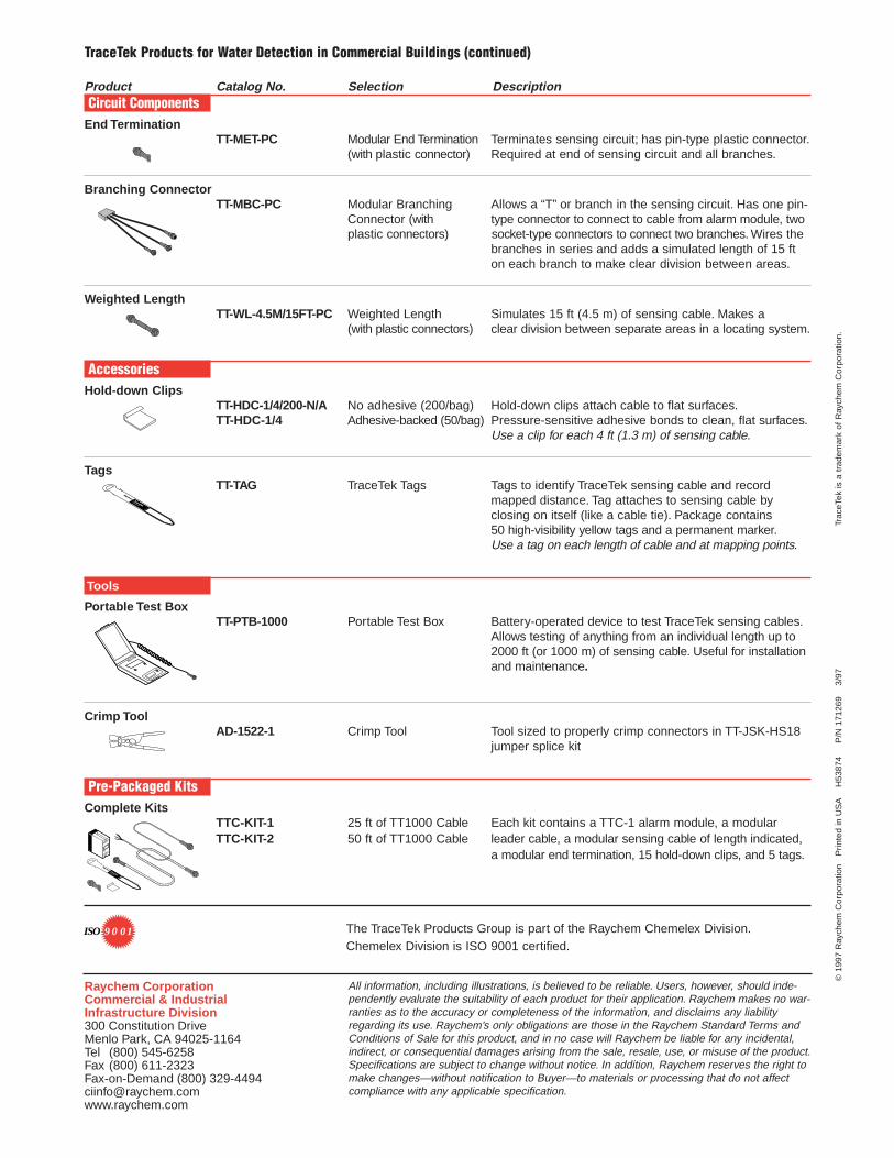
Product Catalog No. Selection DescriptionAlarm Modules
TTDM Alarm and TTDM-1 115 Vac Supply Alarm and locating module; indicates liquid location withLocating Module TTDM-2 230 Vac Supply digital display. Monitors up to 5000 ft (1500 m) of sensing
TTDM-24 24 V Supply cable. Metal enclosure, NEMA 12. Data logging.Outputs: Audible alarm, 4 LEDs, backlit LCD
3 DPDT Form C relays (leak, service, and fault)4-20 mA analog output
For details on approvals Serial port configurable for RS-232 or RS-485see data sheets.
TTA Alarm ModuleTTA-1 115 or 240 Vac Supply Nonlocating single-channel alarm module.
Monitors up to 100 ft (30 m) of sensing cable.Metal enclosure, NEMA 1.Outputs: Audible alarm, 3 LEDs
4PDT Form C relay (leak or fault)
TTC Alarm ModuleTTC-1 24 V Supply Nonlocating single-channel alarm module. Monitors up to
100 ft (30 m) of sensing cable. Plastic enclosure, NEMA 1.Outputs: 3 LEDs
DPDT Form C relay (leak)SPDT Form C relay (fault)
TT-DRC Din Rail Clip Mounting clip for attachment to DIN rail in electrical panel.
External or Remote Alarm
TTE-XAL External Audible Alarm 95 dB alarm triggered by relay closure; requires 24 V supply.
Jumper CablesModular Leader Cable
TT-MLC-PC Modular Leader Cable Cable with one end prepared for connection to terminals(with plastic connector) in module (or for splicing to bulk jumper cable), and with Length: 12 ft (3.5 m) socket-type plastic connector at other end.
Modular Jumper CableTT-MJC-x*-PC Modular Jumper Cable Jumper cable with pin-type plastic connector at one end;
TT-MJC-1M/3FT-PC 1 m 3 ft socket-type plastic connector at other end.TT-MJC-3M/10FT-PC 3 m 10 ftTT-MJC-7.5M/25FT-PC 7.5 m 25 ftTT-MJC-15M/50FT-PC 15 m 50 ft *Cable lengthTT-MJC-30M/100FT-PC 30 m 100 ft
Bulk Jumper CableTT-JC-76M/250FT Bulk Jumper Cable Bulk jumper cable with four color-coded 18 AWG
(250-ft reel) conductors. Connectors not included.
Jumper Splice KitTT-JSK-HS18 Jumper Splice Kit Splice kit for jumper cable; contains parts for 5 splices.
Includes 20 crimps and 5 heat-shrinkable tubes.For use with 18 AWG jumper wire.
Sensing CablesWater Sensing Cable
TT1000-x*-PC Modular Sensing Cable TT1000 water sensing cable with pin-type plastic connector TT1000-1M/3FT-PC 1 m 3 ft at one end, socket-type plastic connector at other end.TT1000-3M/10FT-PC 3 m 10 ftTT1000-7.5M/25FT-PC 7.5 m 25 ftTT1000-15M/50FT-PC 15 m 50 ft *Cable length
®
R
®
R
R RC
F M
APPROVED
PRODUCT SERVICE geprüfteSicherheit
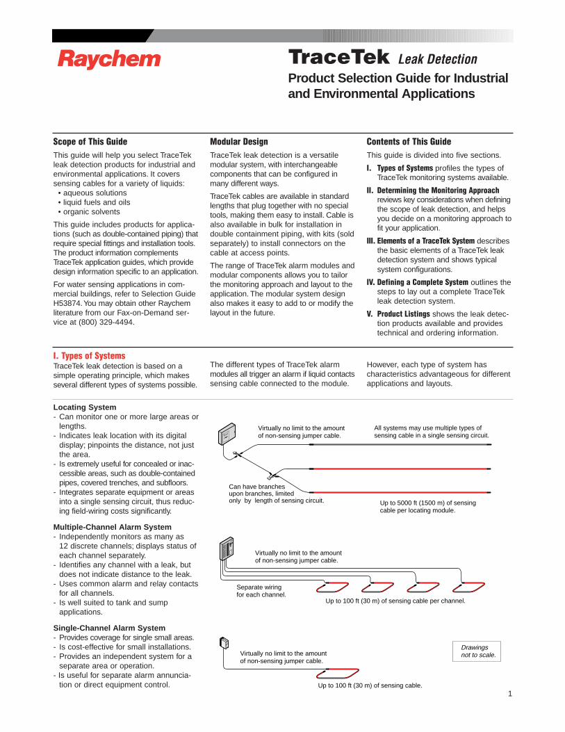
TraceTek Products for Water Detection in Commercial Buildings
Product Catalog No. Selection DescriptionCircuit Components
End TerminationTT-MET-PC Modular End Termination Terminates sensing circuit; has pin-type plastic connector.
(with plastic connector) Required at end of sensing circuit and all branches.
Branching ConnectorTT-MBC-PC Modular Branching Allows a “T” or branch in the sensing circuit. Has one pin-
Connector (with type connector to connect to cable from alarm module, two plastic connectors) socket-type connectors to connect two branches. Wires the
branches in series and adds a simulated length of 15 fton each branch to make clear division between areas.
Weighted LengthTT-WL-4.5M/15FT-PC Weighted Length Simulates 15 ft (4.5 m) of sensing cable. Makes a
(with plastic connectors) clear division between separate areas in a locating system.
AccessoriesHold-down Clips
TT-HDC-1/4/200-N/A No adhesive (200/bag) Hold-down clips attach cable to flat surfaces.TT-HDC-1/4 Adhesive-backed (50/bag) Pressure-sensitive adhesive bonds to clean, flat surfaces.
Use a clip for each 4 ft (1.3 m) of sensing cable.
TagsTT-TAG TraceTek Tags Tags to identify TraceTek sensing cable and record
mapped distance. Tag attaches to sensing cable by closing on itself (like a cable tie). Package contains 50 high-visibility yellow tags and a permanent marker.Use a tag on each length of cable and at mapping points.
Tools
Portable Test BoxTT-PTB-1000 Portable Test Box Battery-operated device to test TraceTek sensing cables.
Allows testing of anything from an individual length up to2000 ft (or 1000 m) of sensing cable. Useful for installationand maintenance.
Crimp ToolAD-1522-1 Crimp Tool Tool sized to properly crimp connectors in TT-JSK-HS18
jumper splice kit
Pre-Packaged KitsComplete Kits
TTC-KIT-1 25 ft of TT1000 Cable Each kit contains a TTC-1 alarm module, a modular TTC-KIT-2 50 ft of TT1000 Cable leader cable, a modular sensing cable of length indicated,
a modular end termination, 15 hold-down clips, and 5 tags.©
1997
Ray
chem
Cor
pora
tion
P
rinte
d in
US
A
H
5387
4
P
/N 1
7126
9
3/9
7
Tr
aceT
ek is
a t
rade
mar
k of
Ray
chem
Cor
pora
tion.
All information, including illustrations, is believed to be reliable. Users, however, should inde-pendently evaluate the suitability of each product for their application. Raychem makes no war-ranties as to the accuracy or completeness of the information, and disclaims any liabilityregarding its use. Raychem’s only obligations are those in the Raychem Standard Terms andConditions of Sale for this product, and in no case will Raychem be liable for any incidental,indirect, or consequential damages arising from the sale, resale, use, or misuse of the product.Specifications are subject to change without notice. In addition, Raychem reserves the right tomake changes—without notification to Buyer—to materials or processing that do not affectcompliance with any applicable specification.
Raychem CorporationCommercial & IndustrialInfrastructure Division300 Constitution DriveMenlo Park, CA 94025-1164Tel (800) 545-6258Fax (800) 611-2323 Fax-on-Demand (800) [email protected]
The TraceTek Products Group is part of the Raychem Chemelex Division.Chemelex Division is ISO 9001 certified.
9 0 01ISO
TraceTek Products for Water Detection in Commercial Buildings (continued)
1
Scope of This GuideThis guide will help you select TraceTekleak detection products for industrial andenvironmental applications. It coverssensing cables for a variety of liquids:
• aqueous solutions• liquid fuels and oils• organic solvents
This guide includes products for applica-tions (such as double-contained piping) thatrequire special fittings and installation tools.The product information complementsTraceTek application guides, which providedesign information specific to an application.
For water sensing applications in com-mercial buildings, refer to Selection GuideH53874.You may obtain other Raychemliterature from our Fax-on-Demand ser-vice at (800) 329-4494.
Modular DesignTraceTek leak detection is a versatilemodular system, with interchangeablecomponents that can be configured inmany different ways.
TraceTek cables are available in standardlengths that plug together with no specialtools, making them easy to install. Cable isalso available in bulk for installation indouble containment piping, with kits (soldseparately) to install connectors on thecable at access points.
The range of TraceTek alarm modules andmodular components allows you to tailorthe monitoring approach and layout to theapplication. The modular system designalso makes it easy to add to or modify thelayout in the future.
Contents of This GuideThis guide is divided into five sections.
I. Types of Systems profiles the types ofTraceTek monitoring systems available.
II. Determining the Monitoring Approachreviews key considerations when definingthe scope of leak detection, and helpsyou decide on a monitoring approach tofit your application.
III. Elements of a TraceTek System describesthe basic elements of a TraceTek leakdetection system and shows typicalsystem configurations.
IV. Defining a Complete System outlines thesteps to lay out a complete TraceTekleak detection system.
V. Product Listings shows the leak detec-tion products available and providestechnical and ordering information.
R TraceTek Leak DetectionProduct Selection Guide for Industrialand Environmental Applications
I. Types of SystemsTraceTek leak detection is based on asimple operating principle, which makesseveral different types of systems possible.
The different types of TraceTek alarmmodules all trigger an alarm if liquid contactssensing cable connected to the module.
However, each type of system has characteristics advantageous for differentapplications and layouts.
Locating System- Can monitor one or more large areas or
lengths.- Indicates leak location with its digital
display; pinpoints the distance, not justthe area.
- Is extremely useful for concealed or inac-cessible areas, such as double-containedpipes, covered trenches, and subfloors.
- Integrates separate equipment or areasinto a single sensing circuit, thus reduc-ing field-wiring costs significantly.
Multiple-Channel Alarm System- Independently monitors as many as
12 discrete channels; displays status ofeach channel separately.
- Identifies any channel with a leak, butdoes not indicate distance to the leak.
- Uses common alarm and relay contactsfor all channels.
- Is well suited to tank and sump applications.
Single-Channel Alarm System- Provides coverage for single small areas.- Is cost-effective for small installations.- Provides an independent system for a
separate area or operation.- Is useful for separate alarm annuncia-
tion or direct equipment control.
Drawingsnot to scale.
Separate wiringfor each channel.
Up to 100 ft (30 m) of sensing cable per channel.
Virtually no limit to the amount of non-sensing jumper cable.
Up to 100 ft (30 m) of sensing cable.
Virtually no limit to the amount of non-sensing jumper cable.
Up to 5000 ft (1500 m) of sensing cable per locating module.
Can have branches upon branches, limited only by length of sensing circuit.
All systems may use multiple types of sensing cable in a single sensing circuit.
Virtually no limit to the amount of non-sensing jumper cable.
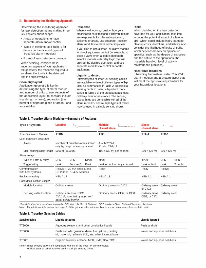
Table 1. TraceTek Alarm Modules—Summary of Features
Type of System Locating Multiple- Single- channel alarm channel alarm
TraceTek Alarm Module TTDM TTG TTA-1 TTC-1
Leak detection coverage
Areas Number of branches/areas limited 4 with TTG-4 1 1 only by length of sensing circuit 12 with TTG-12
Max. sensing cable length 5000 ft (1500 m) 100 ft (30 m) per channel 100 ft (30 m) 100 ft (30 m)
Alarm relays
Type of Form C relay DPDT DPDT DPDT 4PDT 4PDT DPDT SPDT
Triggered by Leak Serv. req'd. Fault Leak or fault on any channel Leak or fault Leak Trouble
Communication Relays, 4–20 mA analog, and Relay Relay Relayswith host systems RS-232 or RS-485, Modbus
Enclosure rating NEMA 12 NEMA 13 NEMA 1 NEMA 1
Hazardous location usage*
Module location Ordinary areas Ordinary areas or CID2 Ordinary areas Ordinary areasor CID2
Sensing cable location Ordinary areas or CID2. Ordinary areas, CID2, or CID1 Ordinary areas, Ordinary areasCID1, if protected by approved CID2, or CID1zener safety barrier.
*See data sheets for details on approvals. CIDI stands for Class I, Division 1, CID2 stands for Class I Division 2 hazardous locations.Note: For additional information, see page 5 of this guide or refer to the applicable product data sheets for complete detail.
Table 2. TraceTek Sensing Cables
Sensing cable Liquids detected Liquids ignored
TT3000 Aqueous solutions and other conductive liquids Fuels and oils
TT5000 Fuels and oils: gasoline, diesel fuel, jet fuel, heating Water and aqueous solutionsoil, motor oil, hydraulic fluid, and other hydrocarbons
TT5001 Organic solvents: acetone, MEK, NMP, TCA, TCE Water and aqueous solutions
Notes: These sensing cables are compatible with any of the TraceTek alarm modules.Multiple types of cables may be used in a single sensing circuit.
2
II. Determining the Monitoring Approach
Geometry/layoutApplication geometry is key in determining the type of alarm moduleand number of units to use. Aspects ofthe application layout to consider includesize (length or area), separation (thenumber of separate pipes or areas), andaccessibility.
ResponseWhen a leak occurs, consider how yourorganization must respond. If different groupsare responsible for different equipment,systems, or areas, use separate TraceTekalarm modules to make ownership clear.
If you plan to use a TraceTek alarm modulefor direct equipment control (for example, toclose a valve when a leak is detected),select a module with relay logic that willprovide the desired operation, and useseparate modules to control separateequipment.
Liquids to detectDifferent types of TraceTek sensing cablesare available to detect different types of liq-uids, as summarized in Table 2. To select asensing cable to detect a liquid not men-tioned in Table 2 or the product data sheets,call Raychem for assistance. The sensingcables listed are compatible with all of thealarm modules, and multiple types of cablesmay be used in a single sensing circuit.
RisksWhen deciding on the leak detection coverage for your application, take intoaccount the potential impact of a leak orspill, which could include injury, damage,cleanup costs, downtime, and liability. Alsoconsider the likelihood of leaks or spills,which depends heavily on applicationspecifics, such as the degree of exposureand the nature of the operations (thematerials handled, level of activity, maintenance practices).
Hazardous locationsIf handling flammables, select TraceTekalarm modules and a system layout thatwill meet the approval requirements foryour hazardous locations.
Determining the monitoring approachfor leak detection means making threekey choices about scope:
• Areas or operations to have separate alarm and/or control
• Types of systems (see Table 1 fordetails on the different types ofTraceTek alarm modules).
• Extent of leak detection coverage
When deciding, consider these important aspects of your application:the geometry, the response required toan alarm, the liquids to be detected,and the risks involved.
3
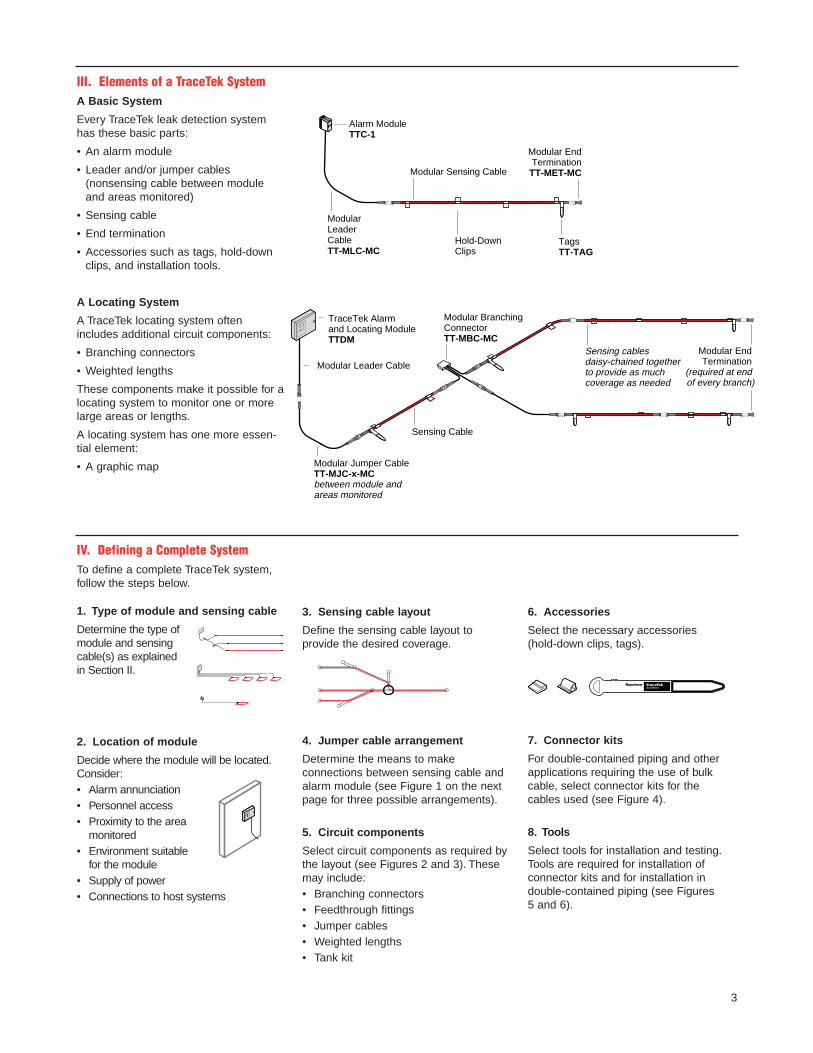
III. Elements of a TraceTek SystemA Basic System
Every TraceTek leak detection systemhas these basic parts:
• An alarm module
• Leader and/or jumper cables (nonsensing cable between moduleand areas monitored)
• Sensing cable
• End termination
• Accessories such as tags, hold-downclips, and installation tools.
A Locating System
A TraceTek locating system oftenincludes additional circuit components:
• Branching connectors
• Weighted lengths
These components make it possible for alocating system to monitor one or morelarge areas or lengths.
A locating system has one more essen-tial element:
• A graphic map Modular Jumper CableTT-MJC-x-MCbetween module and areas monitored
Sensing cablesdaisy-chained togetherto provide as much coverage as needed
Modular BranchingConnectorTT-MBC-MC
Modular Leader Cable
Sensing Cable
TraceTek Alarm and Locating ModuleTTDM
Modular End Termination
(required at end of every branch)
Modular Sensing Cable
Modular Leader CableTT-MLC-MC
Alarm ModuleTTC-1
Modular EndTerminationTT-MET-MC
TagsTT-TAG
Hold-DownClips
IV. Defining a Complete SystemTo define a complete TraceTek system,follow the steps below.
1. Type of module and sensing cable
Determine the type ofmodule and sensingcable(s) as explained in Section II.
2. Location of module
Decide where the module will be located.Consider:• Alarm annunciation• Personnel access• Proximity to the area
monitored• Environment suitable
for the module• Supply of power• Connections to host systems
3. Sensing cable layout
Define the sensing cable layout to provide the desired coverage.
4. Jumper cable arrangement
Determine the means to make connections between sensing cable andalarm module (see Figure 1 on the nextpage for three possible arrangements).
5. Circuit components
Select circuit components as required bythe layout (see Figures 2 and 3). Thesemay include:• Branching connectors• Feedthrough fittings• Jumper cables• Weighted lengths• Tank kit
6. Accessories
Select the necessary accessories (hold-down clips, tags).
7. Connector kits
For double-contained piping and otherapplications requiring the use of bulkcable, select connector kits for the cables used (see Figure 4).
8. Tools
Select tools for installation and testing.Tools are required for installation of connector kits and for installation in double-contained piping (see Figures 5 and 6).
4
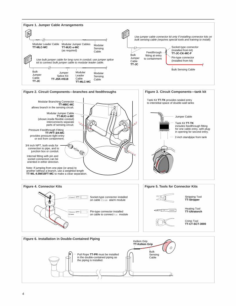
Pressure Feedthrough Fitting TT-PFT-3/4-MC
provides pressure-tight entryor exit from containment.
Internal fitting with pin and socket connectors can be oriented in either direction.
Modular Jumper CableTT-MJC-x-MC
(shown inside flexible conduit)interconnects separateparts of sensing circuit.
3/4 inch NPT, both ends for connection to pipe, and to
junction box or conduit.
Modular Branching ConnectorTT-MBC-MC
allows branch in the sensing circuit.
Note: If jumping from one pipe (or area) to another without a branch, use a weighted length TT-WL-4.5M/15FT-MC to make a clear separation.
Figure 2. Circuit Components—branches and feedthroughs
Socket-type connector installedon cable from alarm module
Pin-type connector installedon cable to connect to module
Figure 4. Connector Kits
Pull Rope TT-PR must be installedin the double-contained piping as the piping is installed.
Bulk Sensing Cable
Kellem GripTT-Kellem Grip
Modular Sensing Cable
Use jumper cable connector kit only if installing connector kits onbulk sensing cable (requires special tools and training to install).
Use bulk jumper cable for long runs in conduit; use jumper splicekit to connect bulk jumper cable to modular leader cable.
Modular Sensing Cable
Modular Leader CableTT-MLC-MC
Modular Jumper CablesTT-MJC-x-MC(as required)
Socket-type connector (installed from kit)TT-JC-CK-MC-F
Pin-type connector (installed from kit)
BulkJumperCableTT-JC
JumperSplice Kit
TT-JSK-HS18
Modular LeaderCableTT-MLC-MC
Bulk Sensing Cable
BulkJumperCableTT-JC
Feedthroughfitting at entry
to containment
Figure 1. Jumper Cable Arrangements
Figure 6. Installation in Double-Contained Piping
Tank Kit TT-TK provides sealed entryto interstitial space of double-wall tanks
Jumper Cable
Tank Kit TT-TK includes feedthrough fitting for one cable entry, with plug- in opening for second entry.
2-inch standpipe from tank
Figure 3. Circuit Components—tank kit
ULTRATORCH
Stripping ToolTT-Stripper
Heating ToolTT-Ultratorch
Crimp ToolTT-CT-SCT-3000
Figure 5. Tools for Connector Kits
V. TraceTek Products for Industrial and Environmental Applications
5
Product Catalog No. Selection DescriptionAlarm Modules
TTDM Alarm and Alarm and locating module; indicates liquid location withLocating Module TTDM-1 115 Vac supply digital display. Monitors up to 5000 ft (1500 m) of sensing
TTDM-2 230 Vac supply cable. Metal enclosure, NEMA 12. Data logging.TTDM-24 24 V supply Outputs: Audible alarm, 4 LEDs, backlit LCD
3 DPDT Form C relays (leak, service, and fault)4–20 mA analog output
For details on approvals Serial port configurable for RS-232 or RS-485
see data sheet.
TTG Alarm ModuleTTG-4 with 4 channels Nonlocating multiple-channel alarm module.TTG-12 with 12 channels Monitors up to 100 ft (30 m) of sensing cable per channel.
(115 or 240 Vac supply Metal enclosure, NEMA 13.for both models) Outputs: Audible alarm, 3 LEDs per channel
4PDT Form C relay (leak or fault in any channel)
TTA Alarm ModuleTTA-1 115 or 240 Vac supply Nonlocating single-channel alarm module.
Monitors up to 100 ft (30 m) of sensing cable.Metal enclosure, NEMA 1.Outputs: Audible alarm, 3 LEDs
4PDT Form C relay (leak or fault)
TTC Alarm ModuleTTC-1 24 V supply Nonlocating single-channel alarm module. Monitors up to
100 ft (30 m) of sensing cable. Plastic enclosure, NEMA 1.Outputs: 3 LEDs
DPDT Form C relay (leak)SPDT Form C relay (fault)
TT-DRC Din Rail Clip Mounting clip for attachment to DIN rail in electrical panel.
External or Remote Alarm
TTE-XAL External Audible Alarm 95 dB alarm triggered by relay closure; requires 24 V supply.
Jumper CablesModular LeaderCable TT-MLC-MC Modular Leader Cable Cable with one end prepared for connection to terminals
(with metal connector) in module (or for splicing to bulk jumper cable), and withLength: 12 ft (3.5 m) socket-type metal connector at other end. Includes connector
oversleeve.
Modular JumperCable TT-MJC-x-MC Modular Jumper Cable Jumper cable in modular lengths with pin-type metal con-
TT-MJC-1M/3FT-MC 1 m 3 ft nector at one end, socket-type metal connector at other TT-MJC-3M/10FT-MC 3 m 10 ft end. Includes connector oversleeve (heat-shrinkable tube)TT-MJC-7.5M/25FT-MC 7.5 m 25 ft to protect connector after installation.TT-MJC-15M/50FT-MC 15 m 50 ftTT-MJC-30M/100FT-MC 30 m 100 ft
Bulk Jumper CableTT-JC-76M/250FT 250 ft reel Jumper cable in bulk on reel. Cable has four color-coded TT-JC Reel: 1000 ft min. 18 AWG conductors. Connectors not included.
2000 ft max.
Jumper Splice KitTT-JSK-HS18 Jumper Splice Kit Splice kit for jumper cable; contains parts for 5 splices.
Includes 20 crimps and 5 heat-shrinkable tubes.For use with 18 AWG jumper wire.
®
R
®
R
R
R RC
F M
APPROVED
PRODUCT SERVICE geprüfteSicherheit
TraceTek Products for Industrial and Environmental Applications
6
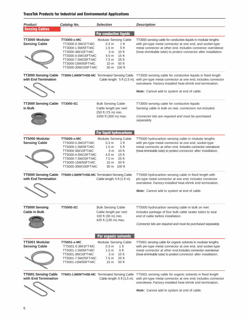
Product Catalog No. Selection DescriptionSensing Cables
For conductive liquidsTT3000 Modular TT3000-x-MC Modular Sensing Cable TT3000 sensing cable for conductive liquids in modular lengthsSensing Cable TT3000-0.3M/1FT-MC 0.3 m 1 ft with pin-type metal connector at one end, and socket-type
TT3000-1.5M/5FT-MC 1.5 m 5 ft metal connector at other end. Includes connector oversleeve TT3000-3M/10FT-MC 3 m 10 ft (heat-shrinkable tube) to protect connector after installation.TT3000-4.5M/15FT-MC 4.5 m 15 ftTT3000-7.5M/25FT-MC 7.5 m 25 ftTT3000-15M/50FT-MC 15 m 50 ftTT3000-30M/100FT-MC 30 m 100 ft
TT3000 Sensing Cable TT3000-1.5M/5FT-HSE-MC Terminated Sensing Cable TT3000 sensing cable for conductive liquids in fixed lengthwith End Termination Cable length: 5 ft (1.5 m) with pin-type metal connector at one end; includes connector
oversleeve. Factory-installed heat-shrink end termination.
Note: Cannot add to system at end of cable.
TT3000 Sensing Cable TT3000-SC Bulk Sensing Cable TT3000 sensing cable for conductive liquidsin Bulk Cable length per reel: Sensing cable in bulk on reel, connectors not included.
250 ft (75 m) min.1000 ft (300 m) max. Connector kits are required and must be purchased
separately.
For liquid hydrocarbonsTT5000 Modular TT5000-x-MC Modular Sensing Cable TT5000 hydrocarbon sensing cable in modular lengthsSensing Cable TT5000-0.3M/1FT-MC 0.3 m 1 ft with pin-type metal connector at one end, socket-type
TT5000-1.5M/5FT-MC 1.5 m 5 ft metal connector at other end. Includes connector oversleeve TT5000-3M/10FT-MC 3 m 10 ft (heat-shrinkable tube) to protect connector after installation.TT5000-4.5M/15FT-MC 4.5 m 15 ftTT5000-7.5M/25FT-MC 7.5 m 25 ftTT5000-15M/50FT-MC 15 m 50 ftTT5000-30M/100FT-MC 30 m 100 ft
TT5000 Sensing Cable TT5000-1.5M/5FT-HSE-MC Terminated Sensing Cable TT5000 hydrocarbon sensing cable in fixed length withwith End Termination Cable length: 5 ft (1.5 m) pin-type metal connector at one end; includes connector
oversleeve. Factory-installed heat-shrink end termination.
Note: Cannot add to system at end of cable
TT5000 Sensing TT5000-SC Bulk Sensing Cable TT5000 hydrocarbon sensing cable in bulk on reel.Cable in Bulk Cable length per reel: Includes package of four bulk cable sealer tubes to seal
100 ft (30 m) min. end of cable before installation.425 ft (130 m) max.
Connector kits are required and must be purchased separately.
For organic solventsTT5001 Modular TT5001-x-MC Modular Sensing Cable TT5001 sensing cable for organic solvents in modular lengthsSensing Cable TT5001-0.3M/1FT-MC 0.3 m 1 ft with pin-type metal connector at one end, and socket-type
TT5001-1.5M/5FT-MC 1.5 m 5 ft metal connector at other end.Includes connector oversleeveTT5001-3M/10FT-MC 3 m 10 ft (heat-shrinkable tube) to protect connector after installation.TT5001-7.5M/25FT-MC 7.5 m 25 ftTT5001-15M/50FT-MC 15 m 50 ft
TT5001 Sensing Cable TT5001-1.5M/5FT-HSE-MC Terminated Sensing Cable TT5001 sensing cable for organic solvents in fixed lengthwith End Termination Cable length: 5 ft (1.5 m) with pin-type metal connector at one end; includes connector
oversleeve. Factory-installed heat-shrink end termination.
Note: Cannot add to system at end of cable.
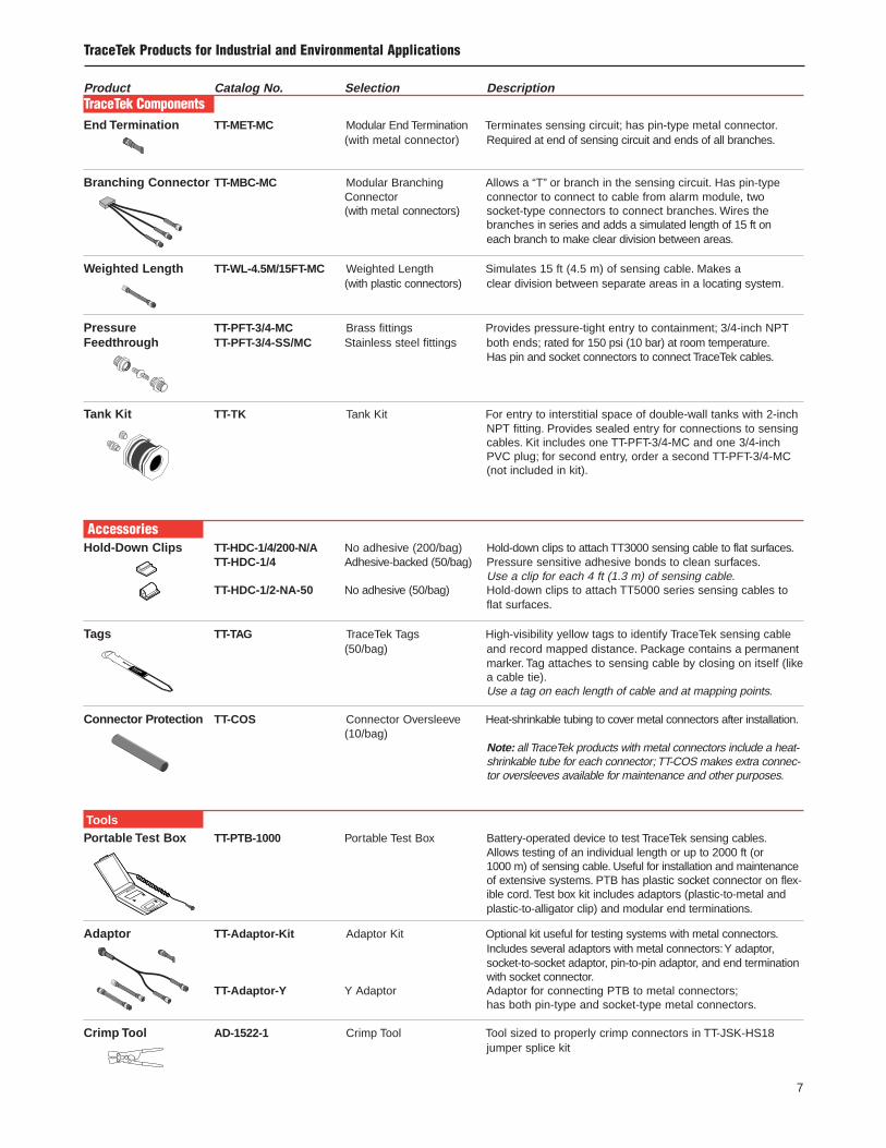
TraceTek Products for Industrial and Environmental Applications
Product Catalog No. Selection DescriptionTraceTek ComponentsEnd Termination TT-MET-MC Modular End Termination Terminates sensing circuit; has pin-type metal connector.
(with metal connector) Required at end of sensing circuit and ends of all branches.
Branching Connector TT-MBC-MC Modular Branching Allows a “T” or branch in the sensing circuit. Has pin-typeConnector connector to connect to cable from alarm module, two (with metal connectors) socket-type connectors to connect branches. Wires the
branches in series and adds a simulated length of 15 ft on each branch to make clear division between areas.
Weighted Length TT-WL-4.5M/15FT-MC Weighted Length Simulates 15 ft (4.5 m) of sensing cable. Makes a(with plastic connectors) clear division between separate areas in a locating system.
Pressure TT-PFT-3/4-MC Brass fittings Provides pressure-tight entry to containment; 3/4-inch NPTFeedthrough TT-PFT-3/4-SS/MC Stainless steel fittings both ends; rated for 150 psi (10 bar) at room temperature.
Has pin and socket connectors to connect TraceTek cables.
Tank Kit TT-TK Tank Kit For entry to interstitial space of double-wall tanks with 2-inchNPT fitting. Provides sealed entry for connections to sensingcables. Kit includes one TT-PFT-3/4-MC and one 3/4-inchPVC plug; for second entry, order a second TT-PFT-3/4-MC(not included in kit).
AccessoriesHold-Down Clips TT-HDC-1/4/200-N/A No adhesive (200/bag) Hold-down clips to attach TT3000 sensing cable to flat surfaces.
TT-HDC-1/4 Adhesive-backed (50/bag) Pressure sensitive adhesive bonds to clean surfaces.Use a clip for each 4 ft (1.3 m) of sensing cable.
TT-HDC-1/2-NA-50 No adhesive (50/bag) Hold-down clips to attach TT5000 series sensing cables toflat surfaces.
Tags TT-TAG TraceTek Tags High-visibility yellow tags to identify TraceTek sensing cable (50/bag) and record mapped distance. Package contains a permanent
marker. Tag attaches to sensing cable by closing on itself (likea cable tie).Use a tag on each length of cable and at mapping points.
Connector Protection TT-COS Connector Oversleeve Heat-shrinkable tubing to cover metal connectors after installation.(10/bag)
Note: all TraceTek products with metal connectors include a heat-shrinkable tube for each connector; TT-COS makes extra connec-tor oversleeves available for maintenance and other purposes.
ToolsPortable Test Box TT-PTB-1000 Portable Test Box Battery-operated device to test TraceTek sensing cables.
Allows testing of an individual length or up to 2000 ft (or 1000 m) of sensing cable. Useful for installation and maintenanceof extensive systems. PTB has plastic socket connector on flex-ible cord. Test box kit includes adaptors (plastic-to-metal andplastic-to-alligator clip) and modular end terminations.
Adaptor TT-Adaptor-Kit Adaptor Kit Optional kit useful for testing systems with metal connectors.Includes several adaptors with metal connectors:Y adaptor,socket-to-socket adaptor, pin-to-pin adaptor, and end terminationwith socket connector.
TT-Adaptor-Y Y Adaptor Adaptor for connecting PTB to metal connectors;has both pin-type and socket-type metal connectors.
Crimp Tool AD-1522-1 Crimp Tool Tool sized to properly crimp connectors in TT-JSK-HS18jumper splice kit
7
TraceTek Products for Industrial and Environmental Applications
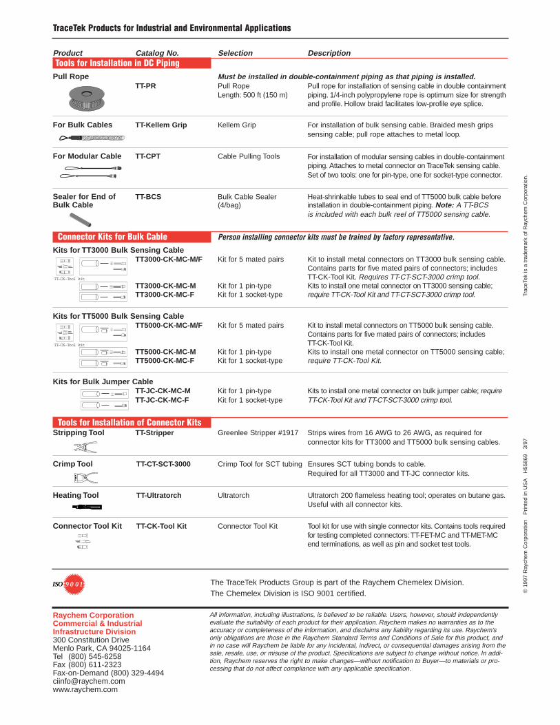
Product Catalog No. Selection DescriptionTools for Installation in DC Piping
Pull Rope Must be installed in double-containment piping as that piping is installed.TT-PR Pull Rope Pull rope for installation of sensing cable in double containment
Length: 500 ft (150 m) piping. 1/4-inch polypropylene rope is optimum size for strengthand profile. Hollow braid facilitates low-profile eye splice.
For Bulk Cables TT-Kellem Grip Kellem Grip For installation of bulk sensing cable. Braided mesh gripssensing cable; pull rope attaches to metal loop.
For Modular Cable TT-CPT Cable Pulling Tools For installation of modular sensing cables in double-containmentpiping. Attaches to metal connector on TraceTek sensing cable.Set of two tools: one for pin-type, one for socket-type connector.
Sealer for End of TT-BCS Bulk Cable Sealer Heat-shrinkable tubes to seal end of TT5000 bulk cable before Bulk Cable (4/bag) installation in double-containment piping. Note: A TT-BCS
is included with each bulk reel of TT5000 sensing cable.
Connector Kits for Bulk Cable Person installing connector kits must be trained by factory representative.
Kits for TT3000 Bulk Sensing CableTT3000-CK-MC-M/F Kit for 5 mated pairs Kit to install metal connectors on TT3000 bulk sensing cable.
Contains parts for five mated pairs of connectors; includesTT-CK-Tool Kit. Requires TT-CT-SCT-3000 crimp tool.
TT3000-CK-MC-M Kit for 1 pin-type Kits to install one metal connector on TT3000 sensing cable;TT3000-CK-MC-F Kit for 1 socket-type require TT-CK-Tool Kit and TT-CT-SCT-3000 crimp tool.
Kits for TT5000 Bulk Sensing CableTT5000-CK-MC-M/F Kit for 5 mated pairs Kit to install metal connectors on TT5000 bulk sensing cable.
Contains parts for five mated pairs of connectors; includes TT-CK-Tool Kit.
TT5000-CK-MC-M Kit for 1 pin-type Kits to install one metal connector on TT5000 sensing cable;TT5000-CK-MC-F Kit for 1 socket-type require TT-CK-Tool Kit.
Kits for Bulk Jumper CableTT-JC-CK-MC-M Kit for 1 pin-type Kits to install one metal connector on bulk jumper cable; requireTT-JC-CK-MC-F Kit for 1 socket-type TT-CK-Tool Kit and TT-CT-SCT-3000 crimp tool.
Tools for Installation of Connector KitsStripping Tool TT-Stripper Greenlee Stripper #1917 Strips wires from 16 AWG to 26 AWG, as required for
connector kits for TT3000 and TT5000 bulk sensing cables.
Crimp Tool TT-CT-SCT-3000 Crimp Tool for SCT tubing Ensures SCT tubing bonds to cable.Required for all TT3000 and TT-JC connector kits.
Heating Tool TT-Ultratorch Ultratorch Ultratorch 200 flameless heating tool; operates on butane gas.Useful with all connector kits.
Connector Tool Kit TT-CK-Tool Kit Connector Tool Kit Tool kit for use with single connector kits. Contains tools requiredfor testing completed connectors: TT-FET-MC and TT-MET-MCend terminations, as well as pin and socket test tools.
ULTRATORCH
TT-CK-Tool kit
TT-CK-Tool kit
©19
97 R
aych
em C
orpo
ratio
n
Prin
ted
in U
SA
H
5586
9
3/97
Tr
aceT
ek is
a t
rade
mar
k of
Ray
chem
Cor
pora
tion.
All information, including illustrations, is believed to be reliable. Users, however, should independentlyevaluate the suitability of each product for their application. Raychem makes no warranties as to theaccuracy or completeness of the information, and disclaims any liability regarding its use. Raychem’sonly obligations are those in the Raychem Standard Terms and Conditions of Sale for this product, andin no case will Raychem be liable for any incidental, indirect, or consequential damages arising from thesale, resale, use, or misuse of the product. Specifications are subject to change without notice. In addi-tion, Raychem reserves the right to make changes—without notification to Buyer—to materials or pro-cessing that do not affect compliance with any applicable specification.
Raychem CorporationCommercial & IndustrialInfrastructure Division300 Constitution DriveMenlo Park, CA 94025-1164Tel (800) 545-6258Fax (800) 611-2323 Fax-on-Demand (800) [email protected]
The TraceTek Products Group is part of the Raychem Chemelex Division.The Chemelex Division is ISO 9001 certified.
9 0 01ISO
R
TT1000TraceTek Water-Sensing Cable
⁄ ⁄ ⁄ ⁄ ⁄ ⁄ ⁄ ⁄ ⁄ ⁄ ⁄ ⁄ ⁄ ⁄ ⁄ ⁄ ⁄ ⁄⁄
⁄⁄
⁄⁄
⁄⁄
⁄⁄
⁄⁄
⁄⁄
⁄⁄⁄⁄⁄⁄⁄⁄⁄⁄⁄⁄⁄⁄⁄⁄⁄⁄⁄⁄⁄⁄⁄⁄⁄⁄⁄⁄
⁄⁄
⁄⁄
⁄⁄
⁄⁄
⁄⁄
⁄
⁄⁄ ⁄ ⁄ ⁄ ⁄ ⁄ ⁄ ⁄ ⁄ ⁄ ⁄ ⁄ ⁄ ⁄ ⁄ ⁄ ⁄ ⁄ ⁄
⁄ ⁄ ⁄ ⁄ ⁄ ⁄ ⁄ ⁄ ⁄ ⁄ ⁄ ⁄ ⁄ ⁄⁄
⁄⁄
⁄⁄
⁄⁄
⁄⁄
⁄⁄
⁄
⁄⁄⁄⁄⁄⁄⁄⁄⁄⁄⁄⁄⁄⁄⁄⁄⁄⁄⁄⁄⁄⁄⁄⁄⁄⁄⁄⁄
⁄⁄
⁄⁄
⁄⁄
⁄⁄
⁄⁄
⁄⁄
⁄ ⁄ ⁄ ⁄ ⁄ ⁄ ⁄ ⁄ ⁄ ⁄ ⁄ ⁄ ⁄ ⁄⁄ ⁄ ⁄ ⁄ ⁄ ⁄ ⁄ ⁄ ⁄ ⁄ ⁄ ⁄ ⁄ ⁄
⁄⁄
⁄⁄
⁄⁄
⁄⁄
⁄⁄
⁄⁄
⁄⁄⁄⁄⁄⁄⁄⁄⁄⁄⁄⁄⁄⁄⁄⁄⁄⁄⁄⁄⁄⁄⁄⁄⁄⁄⁄⁄
⁄⁄
⁄⁄
⁄⁄
⁄⁄
⁄⁄
⁄⁄
⁄ ⁄ ⁄ ⁄ ⁄ ⁄ ⁄ ⁄ ⁄ ⁄ ⁄ ⁄ ⁄ ⁄
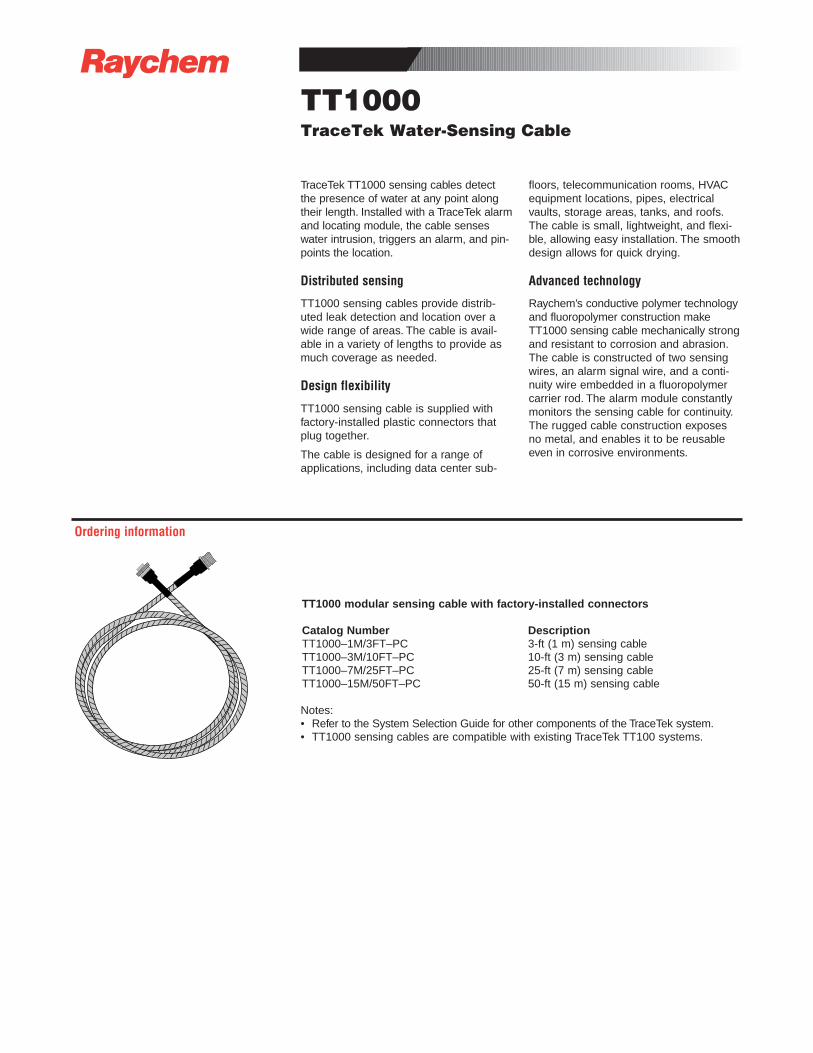
TraceTek TT1000 sensing cables detectthe presence of water at any point alongtheir length. Installed with a TraceTek alarmand locating module, the cable senseswater intrusion, triggers an alarm, and pin-points the location.
Distributed sensing
TT1000 sensing cables provide distrib-uted leak detection and location over awide range of areas. The cable is avail-able in a variety of lengths to provide asmuch coverage as needed.
Design flexibility
TT1000 sensing cable is supplied withfactory-installed plastic connectors thatplug together.
The cable is designed for a range ofapplications, including data center sub-
floors, telecommunication rooms, HVACequipment locations, pipes, electricalvaults, storage areas, tanks, and roofs.The cable is small, lightweight, and flexi-ble, allowing easy installation. The smoothdesign allows for quick drying.
Advanced technology
Raychem’s conductive polymer technologyand fluoropolymer construction makeTT1000 sensing cable mechanically strongand resistant to corrosion and abrasion.The cable is constructed of two sensingwires, an alarm signal wire, and a conti-nuity wire embedded in a fluoropolymercarrier rod. The alarm module constantlymonitors the sensing cable for continuity.The rugged cable construction exposesno metal, and enables it to be reusableeven in corrosive environments.
TT1000 modular sensing cable with factory-installed connectors
Catalog Number DescriptionTT1000–1M/3FT–PC 3-ft (1 m) sensing cableTT1000–3M/10FT–PC 10-ft (3 m) sensing cableTT1000–7M/25FT–PC 25-ft (7 m) sensing cableTT1000–15M/50FT–PC 50-ft (15 m) sensing cable
Notes:• Refer to the System Selection Guide for other components of the TraceTek system.• TT1000 sensing cables are compatible with existing TraceTek TT100 systems.
Ordering information
©19
90 R
aych
em C
orpo
ratio
n
Prin
ted
in U
SA
H
5387
0
10/9
6
T
race
Tek
is a
tra
dem
ark
of R
aych
em C
orpo
ratio
n.
All information, including illustrations, is believed to be reliable. Users, however, should independentlyevaluate the suitability of each product for their application. Raychem makes no warranties as to theaccuracy or completeness of the information, and disclaims any liability regarding its use. Raychem’sonly obligations are those in the Raychem Standard Terms and Conditions of Sale for this product, andin no case will Raychem be liable for any incidental, indirect, or consequential damages arising fromthe sale, resale, use, or misuse of the product. Specifications are subject to change without notice. Inaddition, Raychem reserves the right to make changes—without notification to Buyer—to materials orprocessing that do not affect compliance with any applicable specification.
Raychem CorporationCommercial & Industrial Infrastructure Division300 Constitution DriveMenlo Park, CA 94025-1164Tel (800) 545-6258Fax (800) 611-2323 Fax-on-Demand (800) [email protected]
TT1000 Water-Sensing Cable
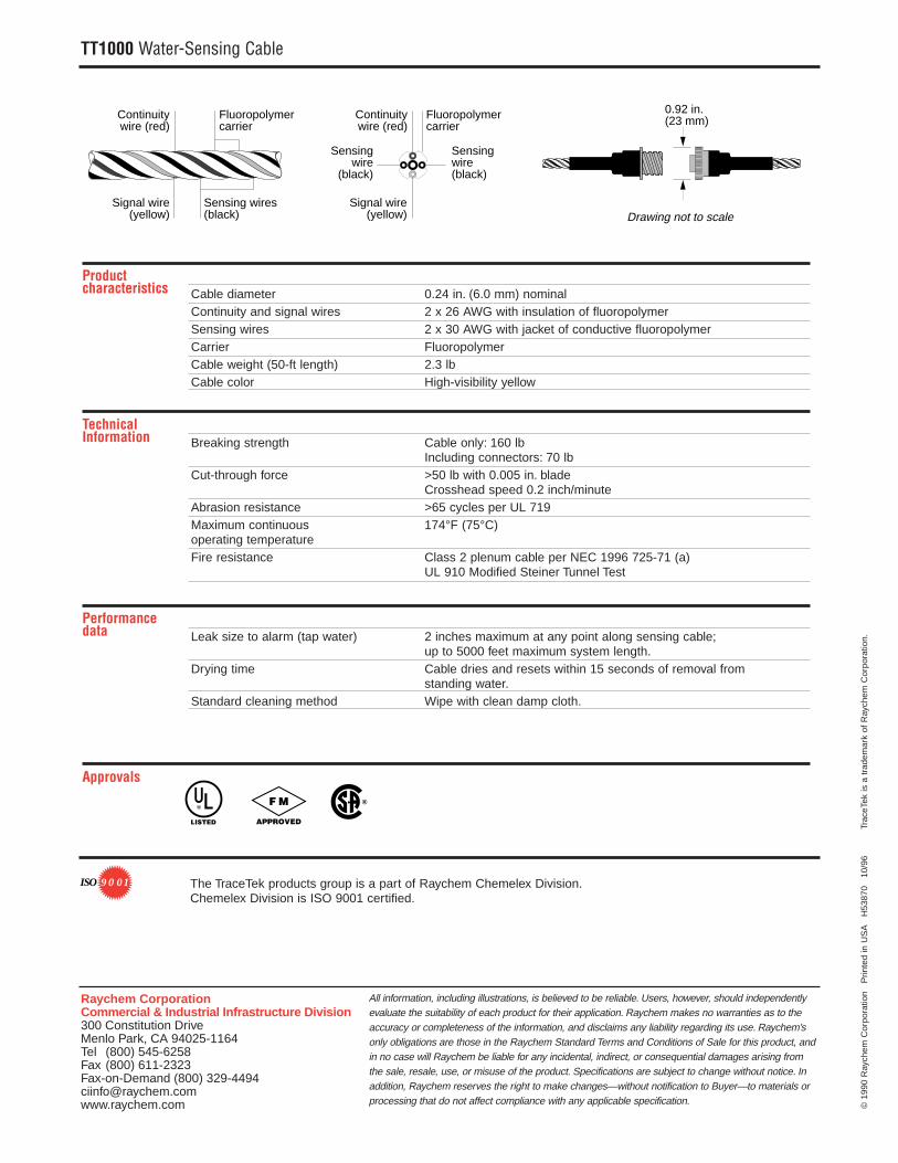
Product characteristics Cable diameter 0.24 in. (6.0 mm) nominal
Continuity and signal wires 2 x 26 AWG with insulation of fluoropolymerSensing wires 2 x 30 AWG with jacket of conductive fluoropolymerCarrier FluoropolymerCable weight (50-ft length) 2.3 lbCable color High-visibility yellow
Technical Information Breaking strength Cable only: 160 lb
Including connectors: 70 lbCut-through force >50 lb with 0.005 in. blade
Crosshead speed 0.2 inch/minuteAbrasion resistance >65 cycles per UL 719Maximum continuous 174°F (75°C) operating temperatureFire resistance Class 2 plenum cable per NEC 1996 725-71 (a)
UL 910 Modified Steiner Tunnel Test
Performancedata Leak size to alarm (tap water) 2 inches maximum at any point along sensing cable;
up to 5000 feet maximum system length.Drying time Cable dries and resets within 15 seconds of removal from
standing water.Standard cleaning method Wipe with clean damp cloth.
Approvals
Fluoropolymercarrier
0.92 in.(23 mm)Fluoropolymer
carrierContinuitywire (red)
Continuitywire (red)
Sensing wire(black)
Sensing wires(black)
Sensingwire
(black)
Signal wire(yellow)
Signal wire(yellow) Drawing not to scale
R
LISTED
F M
APPROVED
®
The TraceTek products group is a part of Raychem Chemelex Division.Chemelex Division is ISO 9001 certified.
9 0 01ISO

R
TT3000TraceTek Sensing Cable for Conductive Liquids
TraceTek TT3000 sensing cable detects thepresence of conductive liquids at any pointalong its length. Most acids and bases andeven deionized water can be sensed andlocated. Installed with a TraceTek alarm andlocating module, the cable senses the pres-ence of fluid, triggers an alarm, and pin-points the location.
Distributed sensing
TT3000 sensing cable provides distrib-uted leak detection and location over awide range of areas. The cable is avail-able in a variety of lengths to provide asmuch coverage as needed.
Design flexibility
TT3000 sensing cable is available withfactory-installed metal connectors thatplug together. The measurement circuit isnot dependent upon the conductivity ofthe leaking fluid. Therefore, the same
cable will detect a wide range of fluidswithout special design considerations orcalibration.
The cable is designed for a variety ofapplications, including floor surfaces, sub-floors, equipment locations, pipes, stor-age tanks, and trenches. The cable issmall, lightweight, and flexible, allowingeasy installation. The smooth designallows quick drying.
Advanced technology
Raychem’s conductive-polymer technologyand fluoropolymer construction makeTT3000 sensing cable mechanically strongand chemically resistant. The cable is constructed of two sensing wires, an alarmsignal wire, and a continuity wire embeddedin a fluoropolymer carrier rod. This ruggedconstruction exposes no metal, and enablesthe cable to be reusable even in corrosiveenvironments.
TT3000 zone sensing cable with factory-installed connector and end termination
Catalog number DescriptionTT3000–Zone–MC 5-ft (1.5 m) sensing cable with
preinstalled heat-shrink end termination
TT3000 modular sensing cables with factory-installed connectors
Catalog number DescriptionTT3000–0.3M/1FT–MC 1-ft (0.3 m) sensing cableTT3000–1M/3FT–MC 3-ft (1 m) sensing cableTT3000–1.5M/5FT–MC 5-ft (1.5 m) sensing cableTT3000–3M/10FT–MC 10-ft (3 m) sensing cableTT3000–4.5M/15FT–MC 15-ft (4.5 m) sensing cableTT3000–7.5M/25FT–MC 25-ft (7.5 m) sensing cableTT3000–15M/50FT–MC 50-ft (15 m) sensing cableTT3000–30M/100FT–MC 100-ft (30 m) sensing cable
TT3000 bulk sensing cable (connector kits required)for installation in double-containment piping
Catalog number DescriptionTT3000–SC Bulk sensing cable on reel,
Minimum length: 250 ft (75 m) Maximum length: 1000 ft (300 m)
Connector kits (not shown)TT3000–CK–MC–M/F Components for five mated pairs of
connectors (includes test tools)TT3000–CK–MC–M One pin-type connectorTT3000–CK–MC–F One socket-type connector
⁄ ⁄ ⁄ ⁄ ⁄ ⁄ ⁄ ⁄ ⁄ ⁄ ⁄ ⁄ ⁄ ⁄⁄
⁄⁄
⁄⁄
⁄⁄
⁄⁄
⁄⁄
⁄
⁄⁄⁄⁄⁄⁄⁄⁄⁄⁄⁄⁄⁄⁄⁄⁄⁄⁄⁄⁄⁄⁄⁄⁄⁄⁄⁄⁄
⁄⁄
⁄⁄
⁄⁄
⁄⁄
⁄⁄
⁄⁄
⁄ ⁄ ⁄ ⁄ ⁄ ⁄ ⁄ ⁄ ⁄ ⁄ ⁄ ⁄ ⁄ ⁄⁄ ⁄ ⁄ ⁄ ⁄ ⁄ ⁄ ⁄ ⁄ ⁄ ⁄ ⁄ ⁄ ⁄
⁄⁄
⁄⁄
⁄⁄
⁄⁄
⁄⁄
⁄⁄
⁄⁄⁄⁄⁄⁄⁄⁄⁄⁄⁄⁄⁄⁄⁄⁄⁄⁄⁄⁄⁄⁄⁄⁄⁄⁄⁄⁄
⁄⁄
⁄⁄
⁄⁄
⁄⁄
⁄⁄
⁄⁄
⁄ ⁄ ⁄ ⁄ ⁄ ⁄ ⁄ ⁄ ⁄ ⁄ ⁄ ⁄ ⁄ ⁄⁄ ⁄ ⁄ ⁄ ⁄ ⁄ ⁄ ⁄ ⁄ ⁄ ⁄ ⁄ ⁄ ⁄
⁄⁄
⁄⁄
⁄⁄
⁄⁄
⁄⁄
⁄⁄
⁄⁄⁄⁄⁄⁄⁄⁄⁄⁄⁄⁄⁄⁄⁄⁄⁄⁄⁄⁄⁄⁄⁄⁄⁄⁄⁄⁄
⁄⁄
⁄⁄
⁄⁄
⁄⁄
⁄⁄
⁄⁄
⁄ ⁄ ⁄ ⁄ ⁄ ⁄ ⁄ ⁄ ⁄ ⁄ ⁄ ⁄ ⁄ ⁄ ⁄ ⁄ ⁄ ⁄ ⁄ ⁄ ⁄ ⁄ ⁄ ⁄ ⁄ ⁄ ⁄ ⁄⁄
⁄⁄
⁄⁄
⁄⁄
⁄⁄
⁄⁄
⁄
⁄⁄⁄⁄⁄⁄⁄⁄⁄⁄⁄⁄⁄⁄⁄⁄⁄⁄⁄⁄⁄⁄⁄⁄⁄⁄⁄⁄
⁄⁄
⁄⁄
⁄⁄
⁄⁄
⁄⁄
⁄⁄
⁄ ⁄ ⁄ ⁄ ⁄ ⁄ ⁄ ⁄ ⁄ ⁄ ⁄ ⁄ ⁄ ⁄
⁄ ⁄ ⁄ ⁄ ⁄ ⁄ ⁄ ⁄ ⁄ ⁄ ⁄ ⁄ ⁄ ⁄⁄
⁄⁄
⁄⁄
⁄⁄
⁄⁄
⁄⁄
⁄⁄
⁄⁄⁄⁄⁄⁄⁄⁄⁄⁄⁄⁄⁄⁄⁄⁄⁄⁄⁄⁄⁄⁄⁄⁄⁄⁄⁄⁄
⁄⁄
⁄⁄
⁄⁄
⁄⁄
⁄⁄
⁄
⁄ ⁄ ⁄ ⁄ ⁄ ⁄ ⁄ ⁄ ⁄ ⁄ ⁄ ⁄ ⁄ ⁄⁄ ⁄ ⁄ ⁄ ⁄ ⁄ ⁄ ⁄ ⁄ ⁄ ⁄ ⁄ ⁄ ⁄
⁄⁄
⁄⁄
⁄⁄
⁄⁄
⁄⁄
⁄⁄
⁄⁄⁄⁄⁄⁄⁄⁄⁄⁄⁄⁄⁄⁄⁄⁄⁄⁄⁄⁄⁄⁄⁄⁄⁄⁄⁄⁄
⁄⁄
⁄⁄
⁄⁄
⁄⁄
⁄⁄
⁄⁄
⁄ ⁄ ⁄ ⁄ ⁄ ⁄ ⁄ ⁄ ⁄ ⁄ ⁄ ⁄ ⁄ ⁄
⁄⁄
⁄⁄
⁄⁄
⁄⁄
⁄
⁄⁄⁄⁄⁄⁄⁄⁄⁄⁄⁄⁄⁄⁄⁄⁄⁄⁄⁄⁄⁄⁄⁄⁄⁄⁄⁄⁄
⁄⁄
⁄⁄
⁄⁄
⁄⁄
⁄⁄
⁄⁄ ⁄ ⁄ ⁄ ⁄ ⁄ ⁄ ⁄ ⁄ ⁄ ⁄ ⁄ ⁄ ⁄ ⁄ ⁄ ⁄ ⁄ ⁄ ⁄ ⁄ ⁄ ⁄ ⁄ ⁄ ⁄ ⁄
⁄⁄
⁄⁄
⁄⁄
⁄⁄
⁄⁄
⁄⁄
⁄⁄
⁄⁄
⁄⁄
⁄
⁄⁄⁄⁄⁄⁄⁄⁄⁄⁄⁄⁄⁄⁄⁄⁄⁄⁄⁄⁄⁄⁄⁄⁄⁄⁄⁄⁄
⁄⁄
⁄⁄
⁄⁄
⁄⁄
⁄⁄
⁄⁄ ⁄ ⁄ ⁄ ⁄ ⁄ ⁄ ⁄ ⁄ ⁄ ⁄ ⁄ ⁄ ⁄ ⁄ ⁄ ⁄ ⁄ ⁄ ⁄ ⁄ ⁄ ⁄ ⁄ ⁄ ⁄ ⁄
⁄⁄
⁄⁄
⁄⁄
⁄⁄
⁄⁄
⁄ ⁄ ⁄ ⁄ ⁄ ⁄ ⁄ ⁄ ⁄ ⁄ ⁄ ⁄ ⁄ ⁄ ⁄
Ordering information
©19
90 R
aych
em C
orpo
ratio
n
Prin
ted
in U
SA
H
5382
9
10/9
6
T
race
Tek
is a
tra
dem
ark
of R
aych
em C
orpo
ratio
n.
All information, including illustrations, is believed to be reliable. Users, however, should independentlyevaluate the suitability of each product for their application. Raychem makes no warranties as to theaccuracy or completeness of the information, and disclaims any liability regarding its use. Raychem’sonly obligations are those in the Raychem Standard Terms and Conditions of Sale for this product,and in no case will Raychem be liable for any incidental, indirect, or consequential damages arisingfrom the sale, resale, use, or misuse of the product. Specifications are subject to change withoutnotice. In addition, Raychem reserves the right to make changes—without notification to Buyer—tomaterials or processing that do not affect compliance with any applicable specification.
Raychem CorporationCommercial & Industrial Infrastructure Division300 Constitution DriveMenlo Park, CA 94025-1164Tel (800) 545-6258Fax (800) 611-2323 Fax-on-Demand (800) [email protected]
TT3000 Sensing Cable for Conductive Liquids
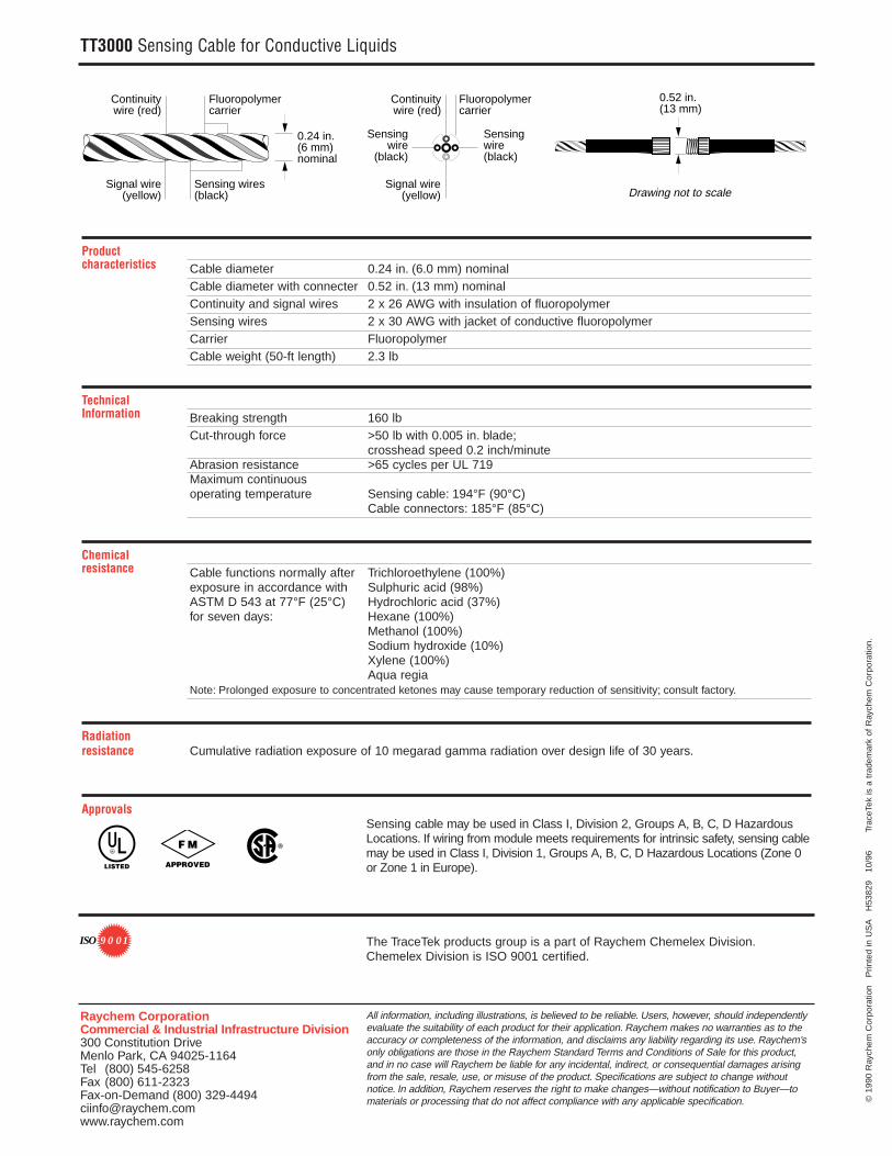
Product characteristics Cable diameter 0.24 in. (6.0 mm) nominal
Cable diameter with connecter 0.52 in. (13 mm) nominalContinuity and signal wires 2 x 26 AWG with insulation of fluoropolymerSensing wires 2 x 30 AWG with jacket of conductive fluoropolymerCarrier FluoropolymerCable weight (50-ft length) 2.3 lb
Technical Information Breaking strength 160 lb
Cut-through force >50 lb with 0.005 in. blade;crosshead speed 0.2 inch/minute
Abrasion resistance >65 cycles per UL 719Maximum continuous operating temperature Sensing cable: 194°F (90°C)
Cable connectors: 185°F (85°C)
Chemical resistance Cable functions normally after Trichloroethylene (100%)
exposure in accordance with Sulphuric acid (98%)ASTM D 543 at 77°F (25°C) Hydrochloric acid (37%)for seven days: Hexane (100%)
Methanol (100%)Sodium hydroxide (10%)Xylene (100%)Aqua regia
Note: Prolonged exposure to concentrated ketones may cause temporary reduction of sensitivity; consult factory.
Radiationresistance Cumulative radiation exposure of 10 megarad gamma radiation over design life of 30 years.
ApprovalsSensing cable may be used in Class I, Division 2, Groups A, B, C, D HazardousLocations. If wiring from module meets requirements for intrinsic safety, sensing cablemay be used in Class I, Division 1, Groups A, B, C, D Hazardous Locations (Zone 0or Zone 1 in Europe).
Fluoropolymercarrier
0.24 in.(6 mm)nominal
0.52 in.(13 mm)
Fluoropolymercarrier
Continuitywire (red)
Continuitywire (red)
Sensing wire(black)
Sensing wires(black)
Sensingwire
(black)
Signal wire(yellow)
Signal wire(yellow) Drawing not to scale
R
LISTED
F M
APPROVED
®
The TraceTek products group is a part of Raychem Chemelex Division.Chemelex Division is ISO 9001 certified.
9 0 01ISO
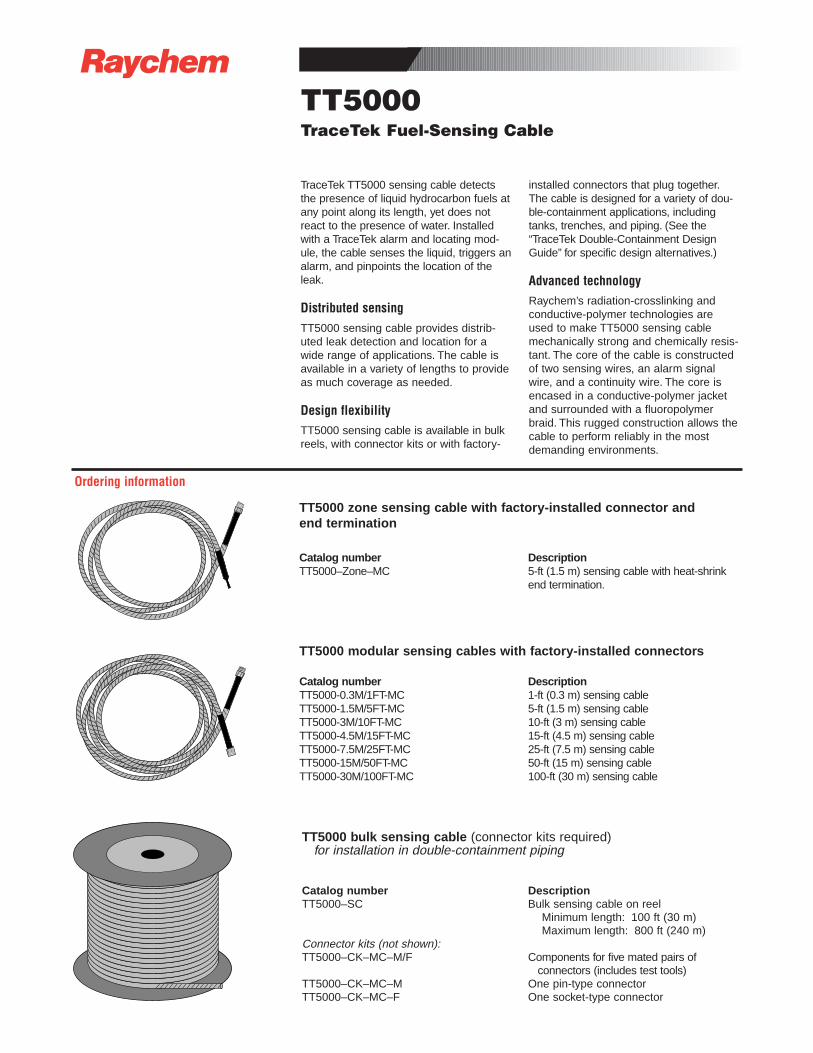
R
TT5000TraceTek Fuel-Sensing Cable
TraceTek TT5000 sensing cable detectsthe presence of liquid hydrocarbon fuels atany point along its length, yet does notreact to the presence of water. Installedwith a TraceTek alarm and locating mod-ule, the cable senses the liquid, triggers analarm, and pinpoints the location of theleak.
Distributed sensingTT5000 sensing cable provides distrib-uted leak detection and location for awide range of applications. The cable isavailable in a variety of lengths to provideas much coverage as needed.
Design flexibilityTT5000 sensing cable is available in bulkreels, with connector kits or with factory-
installed connectors that plug together.The cable is designed for a variety of dou-ble-containment applications, includingtanks, trenches, and piping. (See the“TraceTek Double-Containment DesignGuide” for specific design alternatives.)
Advanced technologyRaychem’s radiation-crosslinking andconductive-polymer technologies areused to make TT5000 sensing cablemechanically strong and chemically resis-tant. The core of the cable is constructedof two sensing wires, an alarm signalwire, and a continuity wire. The core isencased in a conductive-polymer jacketand surrounded with a fluoropolymerbraid. This rugged construction allows thecable to perform reliably in the mostdemanding environments.
⁄ ⁄ ⁄ ⁄ ⁄ ⁄ ⁄ ⁄ ⁄ ⁄ ⁄ ⁄ ⁄ ⁄⁄
⁄⁄
⁄⁄
⁄⁄
⁄⁄
⁄⁄
⁄
⁄⁄⁄⁄⁄⁄⁄⁄⁄⁄⁄⁄⁄⁄⁄⁄⁄⁄⁄⁄⁄⁄⁄⁄⁄⁄⁄⁄
⁄⁄
⁄⁄
⁄⁄
⁄⁄
⁄⁄
⁄⁄
⁄ ⁄ ⁄ ⁄ ⁄ ⁄ ⁄ ⁄ ⁄ ⁄ ⁄ ⁄ ⁄ ⁄⁄ ⁄ ⁄ ⁄ ⁄ ⁄ ⁄ ⁄ ⁄ ⁄ ⁄ ⁄ ⁄ ⁄
⁄⁄
⁄⁄
⁄⁄
⁄⁄
⁄⁄
⁄⁄
⁄⁄⁄⁄⁄⁄⁄⁄⁄⁄⁄⁄⁄⁄⁄⁄⁄⁄⁄⁄⁄⁄⁄⁄⁄⁄⁄⁄
⁄⁄
⁄⁄
⁄⁄
⁄⁄
⁄⁄
⁄⁄
⁄ ⁄ ⁄ ⁄ ⁄ ⁄ ⁄ ⁄ ⁄ ⁄ ⁄ ⁄ ⁄ ⁄⁄ ⁄ ⁄ ⁄ ⁄ ⁄ ⁄ ⁄ ⁄ ⁄ ⁄ ⁄ ⁄ ⁄
⁄⁄
⁄⁄
⁄⁄
⁄⁄
⁄⁄
⁄⁄
⁄⁄⁄⁄⁄⁄⁄⁄⁄⁄⁄⁄⁄⁄⁄⁄⁄⁄⁄⁄⁄⁄⁄⁄⁄⁄⁄⁄
⁄⁄
⁄⁄
⁄⁄
⁄⁄
⁄⁄
⁄⁄
⁄ ⁄ ⁄ ⁄ ⁄ ⁄ ⁄ ⁄ ⁄ ⁄ ⁄ ⁄ ⁄ ⁄ ⁄ ⁄ ⁄ ⁄ ⁄ ⁄ ⁄ ⁄ ⁄ ⁄ ⁄ ⁄ ⁄ ⁄⁄
⁄⁄
⁄⁄
⁄⁄
⁄⁄
⁄⁄
⁄
⁄⁄⁄⁄⁄⁄⁄⁄⁄⁄⁄⁄⁄⁄⁄⁄⁄⁄⁄⁄⁄⁄⁄⁄⁄⁄⁄⁄
⁄⁄
⁄⁄
⁄⁄
⁄⁄
⁄⁄
⁄⁄
⁄ ⁄ ⁄ ⁄ ⁄ ⁄ ⁄ ⁄ ⁄ ⁄ ⁄ ⁄ ⁄ ⁄
⁄ ⁄ ⁄ ⁄ ⁄ ⁄ ⁄ ⁄ ⁄ ⁄ ⁄ ⁄ ⁄ ⁄⁄
⁄⁄
⁄⁄
⁄⁄
⁄⁄
⁄⁄
⁄
⁄⁄⁄⁄⁄⁄⁄⁄⁄⁄⁄⁄⁄⁄⁄⁄⁄⁄⁄⁄⁄⁄⁄⁄⁄⁄⁄⁄
⁄⁄
⁄⁄
⁄⁄
⁄⁄
⁄⁄
⁄⁄
⁄ ⁄ ⁄ ⁄ ⁄ ⁄ ⁄ ⁄ ⁄ ⁄ ⁄ ⁄ ⁄ ⁄⁄ ⁄ ⁄ ⁄ ⁄ ⁄ ⁄ ⁄ ⁄ ⁄ ⁄ ⁄ ⁄ ⁄
⁄⁄
⁄⁄
⁄⁄
⁄⁄
⁄⁄
⁄⁄
⁄⁄⁄⁄⁄⁄⁄⁄⁄⁄⁄⁄⁄⁄⁄⁄⁄⁄⁄⁄⁄⁄⁄⁄⁄⁄⁄⁄
⁄⁄
⁄⁄
⁄⁄
⁄⁄
⁄⁄
⁄⁄
⁄ ⁄ ⁄ ⁄ ⁄ ⁄ ⁄ ⁄ ⁄ ⁄ ⁄ ⁄ ⁄ ⁄
⁄⁄
⁄⁄
⁄⁄
⁄⁄
⁄
⁄⁄⁄⁄⁄⁄⁄⁄⁄⁄⁄⁄⁄⁄⁄⁄⁄⁄⁄⁄⁄⁄⁄⁄⁄⁄⁄⁄
⁄⁄
⁄⁄
⁄⁄
⁄⁄
⁄⁄
⁄⁄ ⁄ ⁄ ⁄ ⁄ ⁄ ⁄ ⁄ ⁄ ⁄ ⁄ ⁄ ⁄ ⁄ ⁄ ⁄ ⁄ ⁄ ⁄ ⁄ ⁄ ⁄ ⁄ ⁄ ⁄ ⁄ ⁄
⁄⁄
⁄⁄
⁄⁄
⁄⁄
⁄⁄
⁄⁄
⁄⁄
⁄⁄
⁄⁄
⁄
⁄⁄⁄⁄⁄⁄⁄⁄⁄⁄⁄⁄⁄⁄⁄⁄⁄⁄⁄⁄⁄⁄⁄⁄⁄⁄⁄⁄
⁄⁄
⁄⁄
⁄⁄
⁄⁄
⁄⁄
⁄⁄ ⁄ ⁄ ⁄ ⁄ ⁄ ⁄ ⁄ ⁄ ⁄ ⁄ ⁄ ⁄ ⁄ ⁄ ⁄ ⁄ ⁄ ⁄ ⁄ ⁄ ⁄ ⁄ ⁄ ⁄ ⁄ ⁄
⁄⁄
⁄⁄
⁄⁄
⁄⁄
⁄⁄
⁄ ⁄ ⁄ ⁄ ⁄ ⁄ ⁄ ⁄ ⁄ ⁄ ⁄ ⁄ ⁄ ⁄ ⁄
TT5000 zone sensing cable with factory-installed connector and end termination
Catalog number DescriptionTT5000–Zone–MC 5-ft (1.5 m) sensing cable with heat-shrink
end termination.
TT5000 modular sensing cables with factory-installed connectors
Catalog number DescriptionTT5000-0.3M/1FT-MC 1-ft (0.3 m) sensing cableTT5000-1.5M/5FT-MC 5-ft (1.5 m) sensing cableTT5000-3M/10FT-MC 10-ft (3 m) sensing cableTT5000-4.5M/15FT-MC 15-ft (4.5 m) sensing cableTT5000-7.5M/25FT-MC 25-ft (7.5 m) sensing cableTT5000-15M/50FT-MC 50-ft (15 m) sensing cableTT5000-30M/100FT-MC 100-ft (30 m) sensing cable
TT5000 bulk sensing cable (connector kits required)for installation in double-containment piping
Catalog number DescriptionTT5000–SC Bulk sensing cable on reel
Minimum length: 100 ft (30 m) Maximum length: 800 ft (240 m)
Connector kits (not shown):TT5000–CK–MC–M/F Components for five mated pairs of
connectors (includes test tools)TT5000–CK–MC–M One pin-type connectorTT5000–CK–MC–F One socket-type connector
Ordering information
©19
94,
1995
Ray
chem
Cor
pora
tion
P
rinte
d in
US
A
H54
785
10
/96
Tra
ceTe
k is
a t
rade
mar
k of
Ray
chem
Cor
pora
tion.
All information, including illustrations, is believed to be reliable. Users, however, should independentlyevaluate the suitability of each product for their application. Raychem makes no warranties as to theaccuracy or completeness of the information, and disclaims any liability regarding its use. Raychem’sonly obligations are those in the Raychem Standard Terms and Conditions of Sale for this product,and in no case will Raychem be liable for any incidental, indirect, or consequential damages arisingfrom the sale, resale, use, or misuse of the product. Specifications are subject to change withoutnotice. In addition, Raychem reserves the right to make changes—without notification to Buyer—tomaterials or processing that do not affect compliance with any applicable specification.
Raychem CorporationCommercial & Industrial Infrastructure Division300 Constitution DriveMenlo Park, CA 94025-1164Tel (800) 545-6258Fax (800) 611-2323 Fax-on-Demand (800) [email protected]
TT5000 Fuel-Sensing Cable
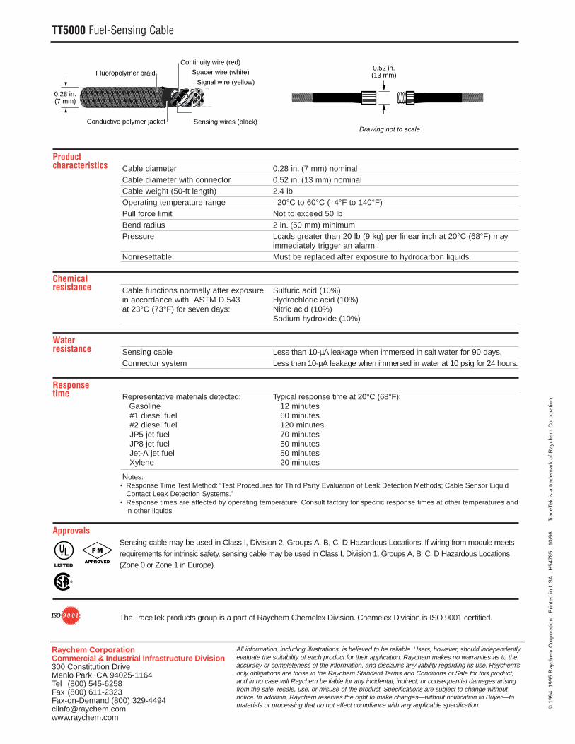
Product characteristics Cable diameter 0.28 in. (7 mm) nominal
Cable diameter with connector 0.52 in. (13 mm) nominalCable weight (50-ft length) 2.4 lbOperating temperature range –20°C to 60°C (–4°F to 140°F)Pull force limit Not to exceed 50 lbBend radius 2 in. (50 mm) minimum Pressure Loads greater than 20 lb (9 kg) per linear inch at 20°C (68°F) may
immediately trigger an alarm.Nonresettable Must be replaced after exposure to hydrocarbon liquids.
Chemical resistance Cable functions normally after exposure Sulfuric acid (10%)
in accordance with ASTM D 543 Hydrochloric acid (10%)at 23°C (73°F) for seven days: Nitric acid (10%)
Sodium hydroxide (10%)
Water resistance Sensing cable Less than 10-µA leakage when immersed in salt water for 90 days.
Connector system Less than 10-µA leakage when immersed in water at 10 psig for 24 hours.
Response time Representative materials detected: Typical response time at 20°C (68°F):
Gasoline 12 minutes #1 diesel fuel 60 minutes #2 diesel fuel 120 minutes JP5 jet fuel 70 minutes JP8 jet fuel 50 minutes Jet-A jet fuel 50 minutes Xylene 20 minutes
Notes:• Response Time Test Method: “Test Procedures for Third Party Evaluation of Leak Detection Methods; Cable Sensor Liquid
Contact Leak Detection Systems.”• Response times are affected by operating temperature. Consult factory for specific response times at other temperatures and
in other liquids.
Approvals Sensing cable may be used in Class I, Division 2, Groups A, B, C, D Hazardous Locations. If wiring from module meetsrequirements for intrinsic safety, sensing cable may be used in Class I, Division 1, Groups A, B, C, D Hazardous Locations(Zone 0 or Zone 1 in Europe).
The TraceTek products group is a part of Raychem Chemelex Division. Chemelex Division is ISO 9001 certified.
Sensing wires (black)
Signal wire (yellow)
Continuity wire (red)
Fluoropolymer braid Spacer wire (white)
Conductive polymer jacket
0.28 in.(7 mm)
0.52 in.(13 mm)
Drawing not to scale
R
F M
APPROVEDLISTED
®
9 0 01ISO
R
TT5001TraceTek Solvent-Sensing Cable
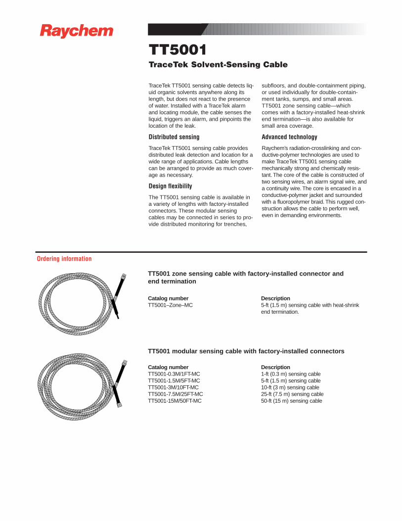
TraceTek TT5001 sensing cable detects liq-uid organic solvents anywhere along itslength, but does not react to the presenceof water. Installed with a TraceTek alarmand locating module, the cable senses theliquid, triggers an alarm, and pinpoints thelocation of the leak.
Distributed sensing
TraceTek TT5001 sensing cable providesdistributed leak detection and location for awide range of applications. Cable lengthscan be arranged to provide as much cover-age as necessary.
Design flexibility
The TT5001 sensing cable is available ina variety of lengths with factory-installedconnectors. These modular sensingcables may be connected in series to pro-vide distributed monitoring for trenches,
subfloors, and double-containment piping,or used individually for double-contain-ment tanks, sumps, and small areas.TT5001 zone sensing cable—whichcomes with a factory-installed heat-shrinkend termination—is also available forsmall area coverage.
Advanced technology
Raychem’s radiation-crosslinking and con-ductive-polymer technologies are used tomake TraceTek TT5001 sensing cablemechanically strong and chemically resis-tant. The core of the cable is constructed oftwo sensing wires, an alarm signal wire, anda continuity wire. The core is encased in aconductive-polymer jacket and surroundedwith a fluoropolymer braid. This rugged con-struction allows the cable to perform well,even in demanding environments.
⁄ ⁄ ⁄ ⁄ ⁄ ⁄ ⁄ ⁄ ⁄ ⁄ ⁄ ⁄ ⁄ ⁄⁄
⁄⁄
⁄⁄
⁄⁄
⁄⁄
⁄⁄
⁄
⁄⁄⁄⁄⁄⁄⁄⁄⁄⁄⁄⁄⁄⁄⁄⁄⁄⁄⁄⁄⁄⁄⁄⁄⁄⁄⁄⁄
⁄⁄
⁄⁄
⁄⁄
⁄⁄
⁄⁄
⁄⁄
⁄ ⁄ ⁄ ⁄ ⁄ ⁄ ⁄ ⁄ ⁄ ⁄ ⁄ ⁄ ⁄ ⁄⁄ ⁄ ⁄ ⁄ ⁄ ⁄ ⁄ ⁄ ⁄ ⁄ ⁄ ⁄ ⁄ ⁄
⁄⁄
⁄⁄
⁄⁄
⁄⁄
⁄⁄
⁄⁄
⁄⁄⁄⁄⁄⁄⁄⁄⁄⁄⁄⁄⁄⁄⁄⁄⁄⁄⁄⁄⁄⁄⁄⁄⁄⁄⁄⁄
⁄⁄
⁄⁄
⁄⁄
⁄⁄
⁄⁄
⁄⁄
⁄ ⁄ ⁄ ⁄ ⁄ ⁄ ⁄ ⁄ ⁄ ⁄ ⁄ ⁄ ⁄ ⁄⁄ ⁄ ⁄ ⁄ ⁄ ⁄ ⁄ ⁄ ⁄ ⁄ ⁄ ⁄ ⁄ ⁄
⁄⁄
⁄⁄
⁄⁄
⁄⁄
⁄⁄
⁄⁄
⁄⁄⁄⁄⁄⁄⁄⁄⁄⁄⁄⁄⁄⁄⁄⁄⁄⁄⁄⁄⁄⁄⁄⁄⁄⁄⁄⁄
⁄⁄
⁄⁄
⁄⁄
⁄⁄
⁄⁄
⁄⁄
⁄ ⁄ ⁄ ⁄ ⁄ ⁄ ⁄ ⁄ ⁄ ⁄ ⁄ ⁄ ⁄ ⁄ ⁄ ⁄ ⁄ ⁄ ⁄ ⁄ ⁄ ⁄ ⁄ ⁄ ⁄ ⁄ ⁄ ⁄⁄
⁄⁄
⁄⁄
⁄⁄
⁄⁄
⁄⁄
⁄
⁄⁄⁄⁄⁄⁄⁄⁄⁄⁄⁄⁄⁄⁄⁄⁄⁄⁄⁄⁄⁄⁄⁄⁄⁄⁄⁄⁄
⁄⁄
⁄⁄
⁄⁄
⁄⁄
⁄⁄
⁄⁄
⁄ ⁄ ⁄ ⁄ ⁄ ⁄ ⁄ ⁄ ⁄ ⁄ ⁄ ⁄ ⁄ ⁄
⁄ ⁄ ⁄ ⁄ ⁄ ⁄ ⁄ ⁄ ⁄ ⁄ ⁄ ⁄ ⁄ ⁄⁄
⁄⁄
⁄⁄
⁄⁄
⁄⁄
⁄⁄
⁄
⁄⁄⁄⁄⁄⁄⁄⁄⁄⁄⁄⁄⁄⁄⁄⁄⁄⁄⁄⁄⁄⁄⁄⁄⁄⁄⁄⁄
⁄⁄
⁄⁄
⁄⁄
⁄⁄
⁄⁄
⁄⁄
⁄ ⁄ ⁄ ⁄ ⁄ ⁄ ⁄ ⁄ ⁄ ⁄ ⁄ ⁄ ⁄ ⁄⁄ ⁄ ⁄ ⁄ ⁄ ⁄ ⁄ ⁄ ⁄ ⁄ ⁄ ⁄ ⁄ ⁄
⁄⁄
⁄⁄
⁄⁄
⁄⁄
⁄⁄
⁄⁄
⁄⁄⁄⁄⁄⁄⁄⁄⁄⁄⁄⁄⁄⁄⁄⁄⁄⁄⁄⁄⁄⁄⁄⁄⁄⁄⁄⁄
⁄⁄
⁄⁄
⁄⁄
⁄⁄
⁄⁄
⁄⁄
⁄ ⁄ ⁄ ⁄ ⁄ ⁄ ⁄ ⁄ ⁄ ⁄ ⁄ ⁄ ⁄ ⁄
⁄⁄
⁄⁄
⁄⁄
⁄⁄
⁄
⁄⁄⁄⁄⁄⁄⁄⁄⁄⁄⁄⁄⁄⁄⁄⁄⁄⁄⁄⁄⁄⁄⁄⁄⁄⁄⁄⁄
⁄⁄
⁄⁄
⁄⁄
⁄⁄
⁄⁄
⁄⁄ ⁄ ⁄ ⁄ ⁄ ⁄ ⁄ ⁄ ⁄ ⁄ ⁄ ⁄ ⁄ ⁄ ⁄ ⁄ ⁄ ⁄ ⁄ ⁄ ⁄ ⁄ ⁄ ⁄ ⁄ ⁄ ⁄
⁄⁄
⁄⁄
⁄⁄
⁄⁄
⁄⁄
⁄⁄
⁄⁄
⁄⁄
⁄⁄
⁄
⁄⁄⁄⁄⁄⁄⁄⁄⁄⁄⁄⁄⁄⁄⁄⁄⁄⁄⁄⁄⁄⁄⁄⁄⁄⁄⁄⁄
⁄⁄
⁄⁄
⁄⁄
⁄⁄
⁄⁄
⁄⁄ ⁄ ⁄ ⁄ ⁄ ⁄ ⁄ ⁄ ⁄ ⁄ ⁄ ⁄ ⁄ ⁄ ⁄ ⁄ ⁄ ⁄ ⁄ ⁄ ⁄ ⁄ ⁄ ⁄ ⁄ ⁄ ⁄
⁄⁄
⁄⁄
⁄⁄
⁄⁄
⁄⁄
TT5001 zone sensing cable with factory-installed connector and end termination
Catalog number DescriptionTT5001–Zone–MC 5-ft (1.5 m) sensing cable with heat-shrink
end termination.
TT5001 modular sensing cable with factory-installed connectors
Catalog number DescriptionTT5001-0.3M/1FT-MC 1-ft (0.3 m) sensing cableTT5001-1.5M/5FT-MC 5-ft (1.5 m) sensing cableTT5001-3M/10FT-MC 10-ft (3 m) sensing cableTT5001-7.5M/25FT-MC 25-ft (7.5 m) sensing cableTT5001-15M/50FT-MC 50-ft (15 m) sensing cable
Ordering information
©19
95 R
aych
em C
orpo
ratio
n
Prin
ted
in U
SA
H
5547
3
5/96
T
race
Tek
is a
tra
dem
ark
of R
aych
em C
orpo
ratio
n.
All information, including illustrations, is believed to be reliable. Users, however, should independentlyevaluate the suitability of each product for their application. Raychem makes no warranties as to theaccuracy or completeness of the information, and disclaims any liability regarding its use. Raychem’sonly obligations are those in the Raychem Standard Terms and Conditions of Sale for this product,and in no case will Raychem be liable for any incidental, indirect, or consequential damages arisingfrom the sale, resale, use, or misuse of the product. Specifications are subject to change withoutnotice. In addition, Raychem reserves the right to make changes—without notification to Buyer—tomaterials or processing that do not affect compliance with any applicable specification.
Raychem CorporationCommercial & Industrial Infrastructure Division300 Constitution DriveMenlo Park, CA 94025-1164Tel (800) 545-6258Fax (800) 611-2323 Fax-on-Demand (800) [email protected]
TT5001 Solvent-Sensing Cable
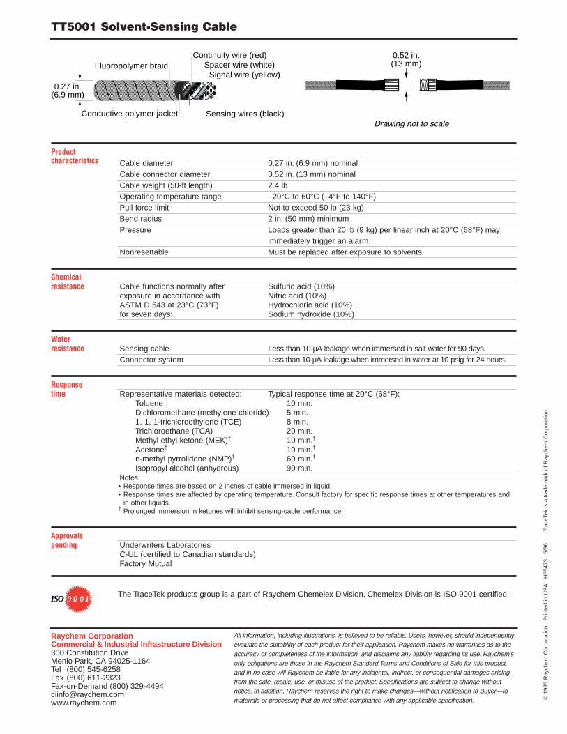
Product characteristics Cable diameter 0.27 in. (6.9 mm) nominal
Cable connector diameter 0.52 in. (13 mm) nominalCable weight (50-ft length) 2.4 lbOperating temperature range –20°C to 60°C (–4°F to 140°F)Pull force limit Not to exceed 50 lb (23 kg)Bend radius 2 in. (50 mm) minimumPressure Loads greater than 20 lb (9 kg) per linear inch at 20°C (68°F) may
immediately trigger an alarm.Nonresettable Must be replaced after exposure to solvents.
Chemical resistance Cable functions normally after Sulfuric acid (10%)
exposure in accordance with Nitric acid (10%)ASTM D 543 at 23°C (73°F) Hydrochloric acid (10%)for seven days: Sodium hydroxide (10%)
Water resistance Sensing cable Less than 10-µA leakage when immersed in salt water for 90 days.
Connector system Less than 10-µA leakage when immersed in water at 10 psig for 24 hours.
Response time Representative materials detected: Typical response time at 20°C (68°F):
Toluene 10 min.Dichloromethane (methylene chloride) 5 min.1, 1, 1-trichloroethylene (TCE) 8 min.Trichloroethane (TCA) 20 min.Methyl ethyl ketone (MEK)† 10 min.†
Acetone† 10 min.†
n-methyl pyrrolidone (NMP)† 60 min.†
Isopropyl alcohol (anhydrous) 90 min.Notes:• Response times are based on 2 inches of cable immersed in liquid.• Response times are affected by operating temperature. Consult factory for specific response times at other temperatures and
in other liquids.† Prolonged immersion in ketones will inhibit sensing-cable performance.
Approvalspending Underwriters Laboratories
C-UL (certified to Canadian standards)Factory Mutual
The TraceTek products group is a part of Raychem Chemelex Division. Chemelex Division is ISO 9001 certified.
Sensing wires (black)
Signal wire (yellow)
Continuity wire (red)Fluoropolymer braid Spacer wire (white)
Conductive polymer jacket
0.27 in.(6.9 mm)
0.52 in.(13 mm)
Drawing not to scale
9 0 01ISO
�
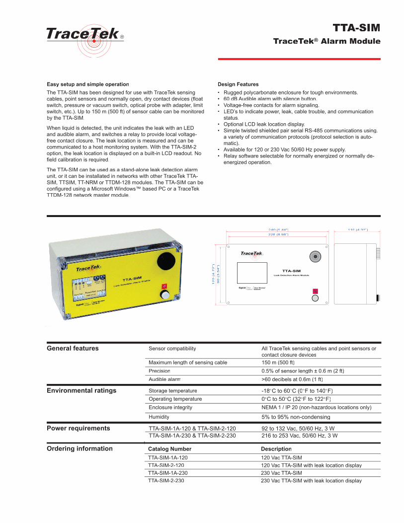
Easy setup and simple operationThe TTA-SIM has been designed for use with TraceTek sensing cables, point sensors and normally open, dry contact devices (fl oat switch, pressure or vacuum switch, optical probe with adapter, limit switch, etc.). Up to 150 m (500 ft) of sensor cable can be monitored by the TTA-SIM.
When liquid is detected, the unit indicates the leak with an LED and audible alarm, and switches a relay to provide local voltage-free contact closure. The leak location is measured and can be communicated to a host monitoring system. With the TTA-SIM-2 option, the leak location is displayed on a built-in LCD readout. No fi eld calibration is required.
The TTA-SIM can be used as a stand-alone leak detection alarm unit, or it can be installated in networks with other TraceTek TTA-SIM, TTSIM, TT-NRM or TTDM-128 modules. The TTA-SIM can be confi gured using a Microsoft Windows™ based PC or a TraceTek TTDM-128 network master module.
Design Features• Rugged polycarbonate enclosure for tough environments.• 60 dB Audible alarm with silence button.• Voltage-free contacts for alarm signaling.• LED’s to indicate power, leak, cable trouble, and communication
status.• Optional LCD leak location display.• Simple twisted shielded pair serial RS-485 communications using.
a variety of communication protocols (protocol selection is auto-matic).
• Available for 120 or 230 Vac 50/60 Hz power supply.• Relay software selectable for normally energized or normally de-
energized operation.
TTA-SIMTraceTek® Alarm Module
General features Sensor compatibility All TraceTek sensing cables and point sensors or contact closure devices
Maximum length of sensing cable 150 m (500 ft)Precision 0.5% of sensor length ± 0.6 m (2 ft)Audible alarm >60 decibels at 0.6m (1 ft)
Environmental ratings Storage temperature -18°C to 60°C (0°F to 140°F)Operating temperature 0°C to 50°C (32°F to 122°F)Enclosure integrity NEMA 1 / IP 20 (non-hazardous locations only)
Humidity 5% to 95% non-condensing
Power requirements TTA-SIM-1A-120 & TTA-SIM-2-120 92 to 132 Vac, 50/60 Hz, 3 WTTA-SIM-1A-230 & TTA-SIM-2-230 216 to 253 Vac, 50/60 Hz, 3 W
Ordering information Catalog Number DescriptionTTA-SIM-1A-120 120 Vac TTA-SIMTTA-SIM-2-120 120 Vac TTA-SIM with leak location displayTTA-SIM-1A-230 230 Vac TTA-SIMTTA-SIM-2-230 230 Vac TTA-SIM with leak location display
��
����
���
��� �������
��
���
���
��
��� ������� ��� �������
�
����������� ��������� ����� ������
Tyco Thermal ControlsWorldwide Headquarters300 Constitution DriveMenlo Park, CA 94025-1164USATel: (800) 545-6258 (within US)
(650) 216-1526Fax: (800) 527-5703 (within US)
(650) 474-7517E-mail: [email protected]
www.tycothermal.com
Important: All information, including illustrations, is believed to be reliable. Users, however, should independently evaluate the suitability of each product for their particular application. Tyco Thermal Controls makes no warranty as to the accuracy or completeness of the information, and disclaims any liability regarding its use. Tyco Thermal Controls’ only obligations are those in the Tyco Thermal Controls Standard Terms and Conditions of Sale for this product, and in no case will Tyco Thermal Controls or its distributors be liable for any incidental, indirect, or consequential damages arising from the sale, resale, use or misuse of the product. Specifi cations are subject to change without notice. In addition, Tyco Thermal Controls reserves the right to make changes – without notifi cation to Buyer – to processing or materials that do not affect compliance with any applicable specifi cation.
Tyco, TraceTek and the TraceTek logo are trademarks or registered trademarks of Tyco Thermal Controls LLC or its affi liates.MODBUS is a trademark of Gould, Inc. OptoMux is a trademark of Opto-22. Metasys is a trademark of John-son Controls. Windows is a trademark of Microsoft Corporation.
©20
04 T
yco
Ther
mal
Con
trols
LLC
H
5754
0 0
4/04
TTA-SIM Alarm ModuleSerial interface Network confi guration RS-485 two wire (twisted shielded pair)
network, 9600 baud, addressable from 1 to 127
Communication protocol MODBUS™, OptoMux™ or Johnson Controls Metasys™Controls Metasys™
Relay contacts Type Form C (SPDT)Action Software selectable; normally
energized or normally de-energized; alarm on leak only, or alarm on either leak or sensor fault
Rating 2 Amps maximum, 250 Vac or 30 Vdc
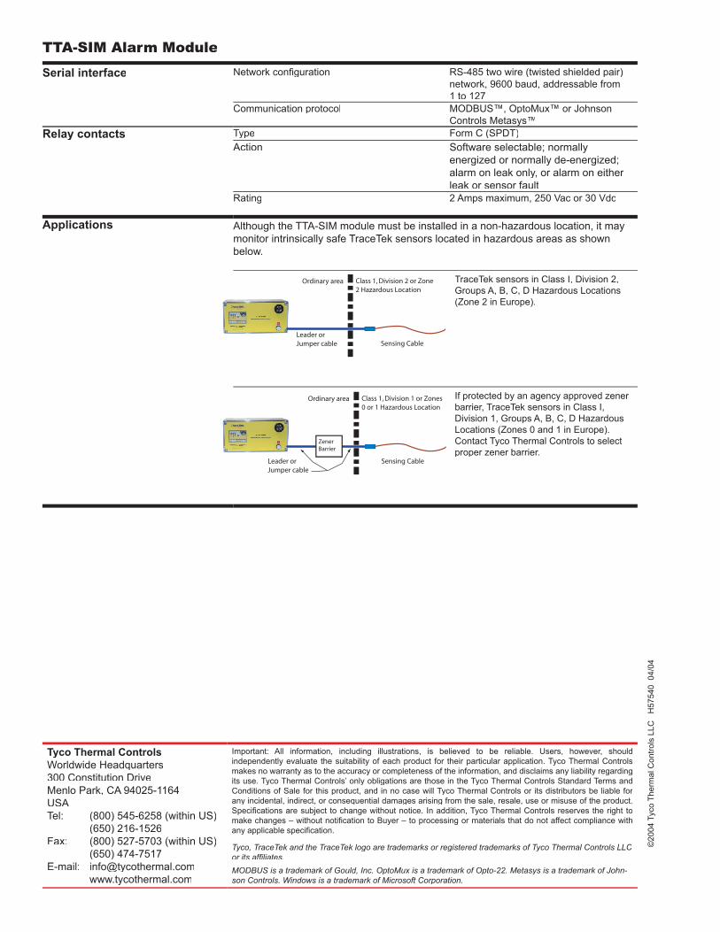
Applications Although the TTA-SIM module must be installed in a non-hazardous location, it may monitor intrinsically safe TraceTek sensors located in hazardous areas as shown below.
TraceTek sensors in Class I, Division 2, Groups A, B, C, D Hazardous Locations (Zone 2 in Europe).
If protected by an agency approved zener barrier, TraceTek sensors in Class I, Division 1, Groups A, B, C, D Hazardous Locations (Zones 0 and 1 in Europe). Contact Tyco Thermal Controls to select proper zener barrier.
����� ���������� � �� ������ �� � ��������� ��������
������� �����
�������� ����
������ �������� �����
������������
����� �� �������� � �� ����� ��������� ��������
������� �����
�������� ����
������ �������� �����
Easy setup and simple operation
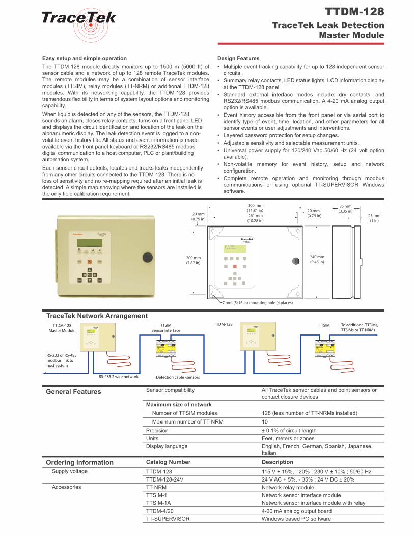
The TTDM-128 module directly monitors up to 1500 m (5000 ft) of
sensor cable and a network of up to 128 remote TraceTek modules.
The remote modules may be a combination of sensor interface
modules (TTSIM), relay modules (TT-NRM) or additional TTDM-128
modules. With its networking capability, the TTDM-128 provides
tremendous fl exibility in terms of system layout options and monitoring
capability.
When liquid is detected on any of the sensors, the TTDM-128
sounds an alarm, closes relay contacts, turns on a front panel LED
and displays the circuit identifi cation and location of the leak on the
alphanumeric display. The leak detection event is logged to a non-
volatile event history fi le. All status and event information is made
available via the front panel keyboard or RS232/RS485 modbus
digital communication to a host computer, PLC or plant/building
automation system.
Each sensor circuit detects, locates and tracks leaks independently
from any other circuits connected to the TTDM-128. There is no
loss of sensitivity and no re-mapping required after an initial leak is
detected. A simple map showing where the sensors are installed is
the only fi eld calibration requirement.
Design Features
• Multiple event tracking capability for up to 128 independent sensor
circuits.
• Summary relay contacts, LED status lights, LCD information display
at the TTDM-128 panel.
• Standard external interface modes include: dry contacts, and
RS232/RS485 modbus communication. A 4-20 mA analog output
option is available.
• Event history accessible from the front panel or via serial port to
identify type of event, time, location, and other parameters for all
sensor events or user adjustments and interventions.
• Layered password protection for setup changes.
• Adjustable sensitivity and selectable measurement units.
• Universal power supply for 120/240 Vac 50/60 Hz (24 volt option
available).
• Non-volatile memory for event history, setup and network
confi guration.
• Complete remote operation and monitoring through modbus
communications or using optional TT-SUPERVISOR Windows
software.
TTDM-128
TraceTek Leak Detection
Master Module
General Features Sensor compatibility All TraceTek sensor cables and point sensors or
contact closure devices
Maximum size of network
Number of TTSIM modules 128 (less number of TT-NRMs installed)
Maximum number of TT-NRM 10
Precision ± 0.1% of circuit length
Units Feet, meters or zones
Display language English, French, German, Spanish, Japanese,
Italian
Ordering Information Catalog Number Description
Supply voltage TTDM-128 115 V + 15%, - 20% ; 230 V ± 10% ; 50/60 Hz
TTDM-128-24V 24 V AC + 5%, - 35% ; 24 V DC ± 20%
Accessories TT-NRM Network relay module
TTSIM-1 Network sensor interface module
TTSIM-1A Network sensor interface module with relay
TTDM-4/20 4-20 mA analog output board
TT-SUPERVISOR Windows based PC software
TraceTek
TTDM
CH01 SIMSIM Normal
7 mm (5/16 in) mounting hole (4 places)
20 mm(0.79 in)
300 mm(11.81 in)261 mm(10.28 in)
240 mm(9.45 in)
85 mm(3.35 in)
25 mm(1 in)
200 mm(7.87 in)
20 mm(0.79 in)
13 14 15 16 17 20 21 22 23 24
8 9 10 11 12
SH
LD RS
–
RS
+ AC AC
RED
GR
N
YEL
BLK
GN
D
TTSIM-1Leak Location ModuleRATING: 24Vac ±10%
50/60 Hz 3VA
NetworkAddress
SH
LD RS
–
RS
+ AC AC
TraceTek
TTDM
CH01 SIMSIM Normal
13-May-2002 15:30
TTDM-128Master Module
TTSIMSensor Interface
TraceTek
TTDM
CH01 SIMSIM Normal
13-May-2002 15:30
RS-485 2 wire network
13 14 15 16 17 20 21 22 23 24
8 9 10 11 12
SH
LD RS
–
RS
+ AC AC
RED
GR
N
YEL
BLK
GN
D
TTSIM-1Leak Location ModuleRATING: 24Vac ±10%
50/60 Hz 3VA
NetworkAddress
SH
LD RS
–
RS
+ AC AC
TTSIM
Detection cable /sensors
TTDM-128
RS-232 or RS-485modbus link tohost system
To additional TTDMs,TTSIMs or TT-NRMs
TraceTek Network Arrangement
Tyco Thermal Controls
300 Constitution Drive
Menlo Park, CA 94025-1164
USA
Tel: (800) 545-6258
Fax: (650) 474-7517
E-mail: [email protected]
www.tycothermal.com
Important: All information, including illustrations, is believed to be reliable. Users, however, should
independently evaluate the suitability of each product for their particular application. Tyco Thermal Controls
makes no warranty as to the accuracy or completeness of the information, and disclaims any liability regarding
its use. Tyco Thermal Controls’ only obligations are those in the Tyco Thermal Controls Standard Terms and
Conditions of Sale for this product, and in no case will Tyco Thermal Controls or its distributors be liable for
any incidental, indirect, or consequential damages arising from the sale, resale, use or misuse of the product.
Specifi cations are subject to change without notice. In addition, Tyco Thermal Controls reserves the right to
make changes – without notifi cation to Buyer – to processing or materials that do not affect compliance with
any applicable specifi cation.
TraceTek and Tyco are trademarks of Tyco Thermal Controls LLC or its affi liates.
2003 T
yco T
he
rmal C
ontr
ols
LLC
H
56859 1
/03
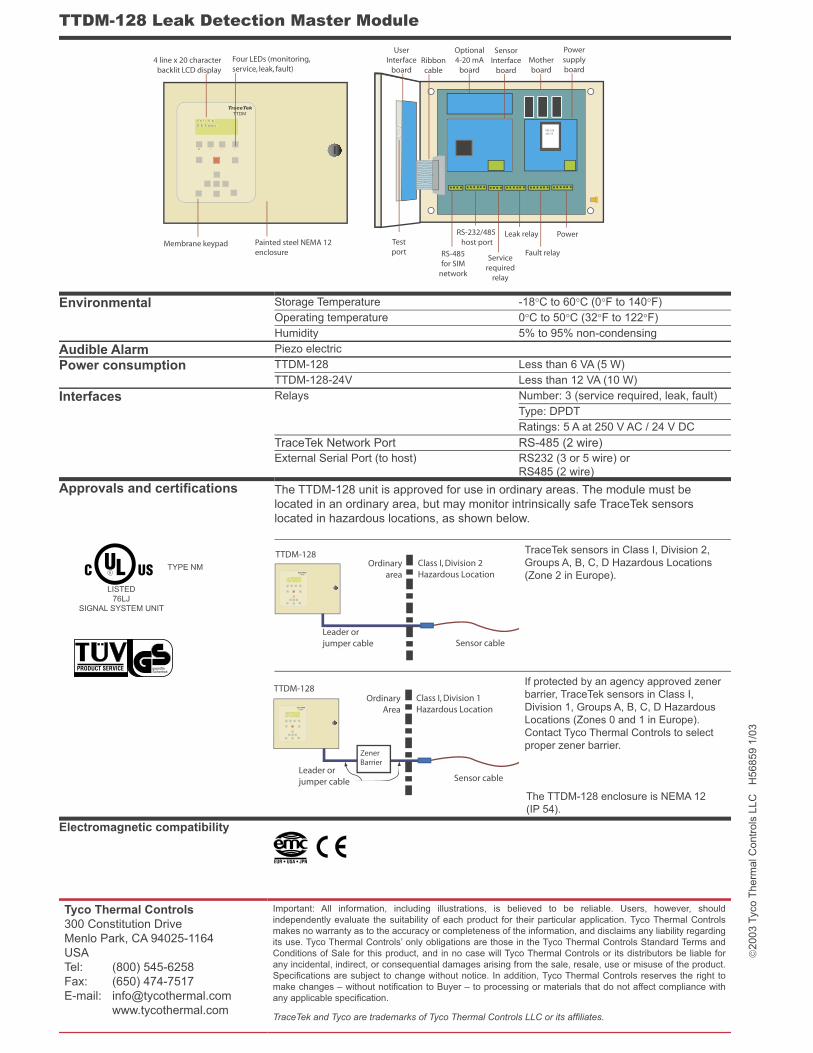
TTDM-128 Leak Detection Master Module
Environmental Storage Temperature -18°C to 60°C (0°F to 140°F)
Operating temperature 0°C to 50°C (32°F to 122°F)
Humidity 5% to 95% non-condensing
Audible Alarm Piezo electric
Power consumption TTDM-128 Less than 6 VA (5 W)
TTDM-128-24V Less than 12 VA (10 W)
Interfaces Relays Number: 3 (service required, leak, fault)
Type: DPDT
Ratings: 5 A at 250 V AC / 24 V DC
TraceTek Network Port RS-485 (2 wire)
External Serial Port (to host) RS232 (3 or 5 wire) or
RS485 (2 wire)
Approvals and certifi cations The TTDM-128 unit is approved for use in ordinary areas. The module must be
located in an ordinary area, but may monitor intrinsically safe TraceTek sensors
located in hazardous locations, as shown below.
TraceTek sensors in Class I, Division 2,
Groups A, B, C, D Hazardous Locations
(Zone 2 in Europe).
If protected by an agency approved zener
barrier, TraceTek sensors in Class I,
Division 1, Groups A, B, C, D Hazardous
Locations (Zones 0 and 1 in Europe).
Contact Tyco Thermal Controls to select
proper zener barrier.
The TTDM-128 enclosure is NEMA 12
(IP 54).
Electromagnetic compatibility
Class I, Division 2Hazardous Location
Sensor cable
Ordinaryarea
Leader orjumper cable
TraceTek
TTDM
CH01 SIMSIM Normal
13-May-2002 15:30
TTDM-128
ZenerBarrier
Class I, Division 1Hazardous Location
Sensor cable
OrdinaryArea
Leader orjumper cable
TraceTek
TTDM
CH01 SIMSIM Normal
13-May-2002 15:30
TTDM-128
TraceTek
TTDM
CH01 SIMSIM Normal
PRI: 220SEC:17
UserInterface
boardRibboncable
Optional4-20 mA
board
SensorInterface
boardMotherboard
Powersupplyboard
Testport RS-485
for SIMnetwork
RS-232/485host port
Servicerequired
relay
Leak relay
Fault relay
Power
4 line x 20 characterbacklit LCD display
Four LEDs (monitoring,service, leak, fault)
Membrane keypad Painted steel NEMA 12enclosure
EUR • USA • JPN
PRODUCT SERVICE geprüfteSicherheit
LISTED
76LJ
SIGNAL SYSTEM UNIT
TYPE NM

DescriptionThe TraceTek TT-NRM Network Relay Module provides the capability to add up to 320 individual alarm relays to a TraceTek TTDM-PLUS / TTSIM leak detection network. The TT-NRM communicates with the TTDM-PLUS via the same RS-485 network used for TTSIMs. The TT-NRM can be installed in a wide variety of configurations, allowing many leak detection system layout possibilities.
ExpandableThe TT-NRM is supplied as a base unit (with power supply, communications interface, DIN rail and end blocks) and separate relay modules. Each relay module contains 2 independently addressable relays. Up to 16 relay modules can be installed on each base unit, and up to 10 base units can be connected to a single TTDM-PLUS. The leak detection network can be expanded at any time with minimal effort.
VersatileThe TT-NRM can be installed in large panels, or wall mounted in its own optional enclosure. TT-NRMs can be centrally located with the TTDM-PLUS, or distributed throughout the leak detection network to minimize wiring costs. The TT-NRM can be used to operate valves, control audible or visual alarms, or interface with other control systems.
TT-NRMTraceTek Network Relay Module
Technical Information Network compatibility TTDM-PLUS / TTSIM networks
Relays Number Up to 32 Form A contacts per TT-NRM
Voltage rating 250 Vac, 30 Vdc
Current rating 1 Amp
Isolation 2.5 kV
Environmental Ratings Storage Temperature -25 °C to 85 °C
Operating Temperature 0 °C to 55 °C
Humidity 5% to 95% non-condensing
Ingress Protection IP 2X
Power requirements Supply voltage 110~240 Volts, AC (50/60 Hz)
Power consumption 6 W
Ordering information Catalog number Description Base unit TT-NRM-BASE Base unit with power supply,
communication interface and 1 relay output module (2 relays)
Relay modules TT-NRM-2RO Relay output module with 2 relays
Networkprocessor
Power supply RS-485 networkconnection module
Relaymodules
Endtermination
Width = 5.0 in. + 0.5 in, per relay module (+ 3.5 in. for optional power supply)= 127 mm + 12 mm per relay module (+ 90 mm for optional power supply)
ON
TxD
IO/RN
IO/ER
RxD
CRC
Address x 1
x 10
750-
312
4 in.(100 mm)
1.5 in.(38 mm)
1.4 in.(35 mm)
0.5 in.(12 mm)
0.5 in.(12 mm)
2 in.(75 mm)
24V 0V L L
N N
L L
N N
1.25 in.(32 mm)
750-512 750-512 750-512 750-600
L LL L
N NN N
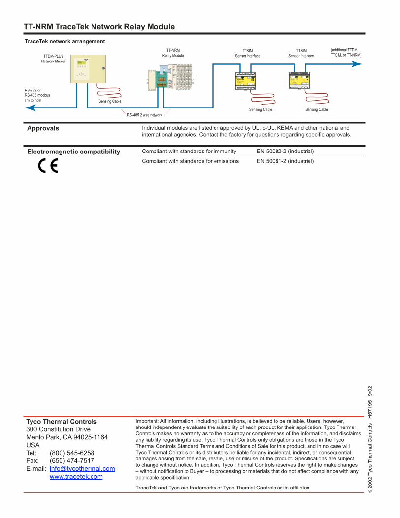
TT-NRM TraceTek Network Relay Module
Tyco Thermal Controls300 Constitution DriveMenlo Park, CA 94025-1164USATel: (800) 545-6258Fax: (650) 474-7517E-mail: [email protected] www.tracetek.com
Important: All information, including illustrations, is believed to be reliable. Users, however, should independently evaluate the suitability of each product for their application. Tyco Thermal Controls makes no warranty as to the accuracy or completeness of the information, and disclaims any liability regarding its use. Tyco Thermal Controls only obligations are those in the Tyco Thermal Controls Standard Terms and Conditions of Sale for this product, and in no case will Tyco Thermal Controls or its distributors be liable for any incidental, indirect, or consequential damages arising from the sale, resale, use or misuse of the product. Specifications are subject to change without notice. In addition, Tyco Thermal Controls reserves the right to make changes – without notification to Buyer – to processing or materials that do not affect compliance with any applicable specification.
TraceTek and Tyco are trademarks of Tyco Thermal Controls or its affiliates.
20
02 T
yco
Ther
mal
Con
trols
H
5719
5 9
/02
Approvals Individual modules are listed or approved by UL, c-UL, KEMA and other national and international agencies. Contact the factory for questions regarding specific approvals.
Electromagnetic compatibility
Compliant with standards for immunity EN 50082-2 (industrial)
Compliant with standards for emissions EN 50081-2 (industrial)
�� �� �� �� �� �� �� �� �� ��
� � �� �� ��
���� ���
��� �� ��
���
���
���
���
���
����������� �������� ������������� ����� ����
����� �� ���
��������������
���� ���
��� �� ��
TraceTek����
���� ������ ������
����������� �����
TTDM-PLUSNetwork Master
TTSIMSensor Interface
RS-485 2 wire network
�� �� �� �� �� �� �� �� �� ��
� � �� �� ��
���� ���
��� �� ��
���
���
���
���
���
����������� �������� ������������� ����� ����
����� �� ���
��������������
���� ���
��� �� ��
Sensing Cable Sensing Cable
RS-232 orRS-485 modbuslink to host
�������� ������� �����������(additional TTDM,TTSIM, or TT-NRM)
TT-NRMRelay Module
ON
TxD
IO/RN
IO/ER
RxD
CRC
Address x 1
x 10
750-
312
24V 0V L L
N N
L L
N N
750-512 750-512 750-512 750-600
L LL L
N NN N
TTSIMSensor Interface
Sensing Cable
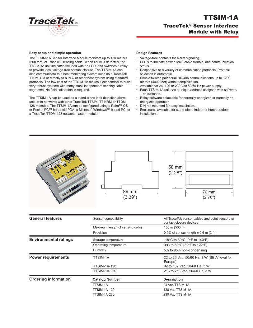
�
Easy setup and simple operationThe TTSIM-1A Sensor Interface Module monitors up to 150 meters (500 feet) of TraceTek sensing cable. When liquid is detected, the TTSIM-1A unit indicates the leak with an LED, and switches a relay to provide local voltage-free contact closure. The TTSIM-1A can also communicate to a host monitoring system such as a TraceTek TTDM-128 or directly to a PLC or other host system using standard protocols. The low cost of the TTSIM-1A makes it economical to build very robust systems with many small independent sensing cable segments. No field calibration is required. The TTSIM-1A can be used as a stand-alone leak detection alarm unit, or in networks with other TraceTek TTSIM, TT-NRM or TTDM-128 modules. The TTSIM-1A can be configured using a Palm™ OS or Pocket PC™ handheld PDA, a Microsoft Windows™ based PC, or a TraceTek TTDM-128 network master module.
Design Features• Voltage-free contacts for alarm signaling.• LED’s to indicate power, leak, cable trouble, and communication
status.• Responsive to a variety of communication protocols. Protocol
selection is automatic. • Simple twisted pair serial RS-485 communications up to 1200
meters (4000 feet) without amplification. • Available for 24, 120 or 230 Vac 50/60 Hz power supply.• Each TTSIM-1A unit has a unique address assigned with software
– no switches.• Relay software selectable for normally energized or normally de-
energized operation• DIN rail mounted for easy installation.• Enclosures available for stand-alone indoor or harsh outdoor
installations.
TTSIM-1ATraceTek® Sensor Interface
Module with Relay
General features Sensor compatibility All TraceTek sensor cables and point sensors or contact closure devices
Maximum length of sensing cable 150 m (500 ft)Precision 0.5% of sensor length ± 0.6 m (2 ft)
Environmental ratings Storage temperature -18°C to 60°C (0°F to 140°F)Operating temperature 0°C to 50°C (32°F to 122°F)Humidity 5% to 95% non-condensing
Power requirements TTSIM-1A 22 to 26 Vac, 50/60 Hz, 3 W (SELV level for Europe)
TTSIM-1A-120 92 to 132 Vac, 50/60 Hz, 3 WTTSIM-1A-230 216 to 253 Vac, 50/60 Hz, 3 W
Ordering information Catalog Number DescriptionTTSIM-1A 24 Vac TTSIM-1ATTSIM-1A-120 120 Vac TTSIM-1ATTSIM-1A-230 230 Vac TTSIM-1A
�� ���������
�� ���������
�� ���������
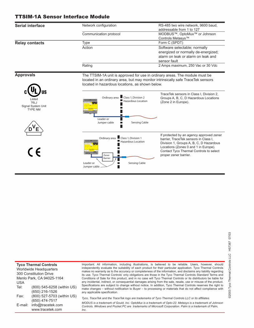
Tyco Thermal ControlsWorldwide Headquarters300 Constitution DriveMenlo Park, CA 94025-1164USATel: (800) 545-6258 (within US) (650) 216-1526Fax: (800) 527-5703 (within US) (650) 474-7517E-mail: [email protected] www.tracetek.com
Important: All information, including illustrations, is believed to be reliable. Users, however, should independently evaluate the suitability of each product for their particular application. Tyco Thermal Controls makes no warranty as to the accuracy or completeness of the information, and disclaims any liability regarding its use. Tyco Thermal Controls’ only obligations are those in the Tyco Thermal Controls Standard Terms and Conditions of Sale for this product, and in no case will Tyco Thermal Controls or its distributors be liable for any incidental, indirect, or consequential damages arising from the sale, resale, use or misuse of the product. Specifications are subject to change without notice. In addition, Tyco Thermal Controls reserves the right to make changes – without notification to Buyer – to processing or materials that do not affect compliance with any applicable specification.
Tyco, TraceTek and the TraceTek logo are trademarks of Tyco Thermal Controls LLC or its affiliates.MODUS is a trademark of Gould, Inc. OptoMux is a trademark of Opto-22. Metasys is a trademark of Johnson Controls. Windows and Pocket PC are trademarks of Microsoft Corporation. Palm is a trademark of Palm, Inc.
©20
03 T
yco
Ther
mal
Con
trols
LLC
H
5738
7 0
7/03
TTSIM-1A Sensor Interface ModuleSerial interface Network configuration RS-485 two wire network, 9600 baud,
addressable from 1 to 127Communication protocol MODBUS™, OptoMux™ or Johnson
Controls Metasys™Relay contacts Type Form C (SPDT)
Action Software selectable; normally energized or normally de-energized; alarm on leak or alarm on leak and sensor fault
Rating 2 Amps maximum, 250 Vac or 30 Vdc
Approvals The TTSIM-1A unit is approved for use in ordinary areas. The module must be located in an ordinary area, but may monitor intrinsically safe TraceTek sensors located in hazardous locations, as shown below.
TraceTek sensors in Class I, Division 2, Groups A, B, C, D Hazardous Locations (Zone 2 in Europe).
If protected by an agency approved zener barrier, TraceTek sensors in Class I, Division 1, Groups A, B, C, D Hazardous Locations (Zones 0 and 1 in Europe). Contact Tyco Thermal Controls to select proper zener barrier.
�� �� �� �� �� �� �� �� �� ��
� � �� �� ��
����� ���������� ���������� ��������
������� �����
�������� ����
������ �������� �����
���
���
���
��� ������������
������� ������ ��������� �� ���
���� ���
���
��
��
��
��
����
���
����
� ���� � ����
�����
����
�������
���� ���
���
��������������
� ��� �� �����
����� ���������� ���������� ��������
������� �����
�������� ����
������ �������� �����
������������
�� �� �� �� �� �� �� �� �� ��
� � �� �� ��
���
���
���
��� ������������
������� ������ ��������� �� ���
���� ���
���
��
��
��
��
����
���
����
� ���� � ����
�����
����
�������
���� ���
���
��������������
� ��� �� �����
Listed76LJ
Signal System UnitTYPE NM
���
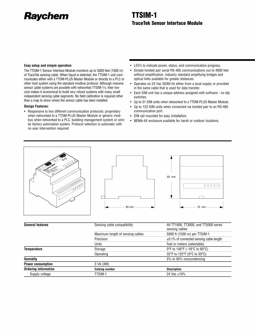
R TTSIM-1TraceTek Sensor Interface Module
85 mm 70 mm
65 mm
Easy setup and simple operationThe TTSIM-1 Sensor Interface Module monitors up to 5000 feet (1500 m)of TraceTek sensing cable. When liquid is detected, the TTSIM-1 unit com-municates either with a TTDM-PLUS Master Module or directly to a PLC orother host system using the standard modbus protocol. Although massivesensor cable systems are possible with networked TTSIM-1’s, their lowcost makes it economical to build very robust systems with many smallindependent sensing cable segments. No field calibration is required otherthan a map to show where the sensor cable has been installed.
Design Features:• Responsive to two different communication protocols: proprietary
when networked to a TTDM-PLUS Master Module or generic mod-bus when networked to a PLC, building management system or simi-lar factory automation system. Protocol selection is automatic withno user intervention required.
• LED’s to indicate power, status, and communication progress.• Simple twisted pair serial RS-485 communications out to 4000 feet
without amplification. Industry standard amplifying bridges andoptical links available for greater distances.
• Operates on 24 Vac 50/60 Hz either from a local supply or providedin the same cable that is used for data transfer.
• Each SIM unit has a unique address assigned with software - no dipswitches.
• Up to 31 SIM units when networked to a TTDM-PLUS Master Module.• Up to 123 SIM units when connected via twisted pair to an RS-485
communication port.• DIN rail mounted for easy installation.• NEMA-4X enclosure available for harsh or outdoor locations.
General features Sensing cable compatibility All TT1000, TT3000, and TT5000 seriessensing cables
Maximum length of sensing cables 5000 ft (1500 m) per TTSIM-1Precision ±0.1% of connected sensing cable lengthUnits Feet or meters (selectable)
Temperature Storage 0°F to 140°F (–18°C to 60°C)Operating 32°F to 122°F (0°C to 50°C)
Humidity 5% to 95% noncondensingPower consumption 3 VA (3W)Ordering information Catalog number Description
Supply voltage TTSIM-1 24 Vac ±10%
SHLD RS– RS+AC
AC
RED GRN YEL BLK GND
TTSIM-1
Leak Location Module
RATING: 24Vac ±10%
50/60 Hz 3VA
Network
Address
SHLD RS– RS+AC
AC
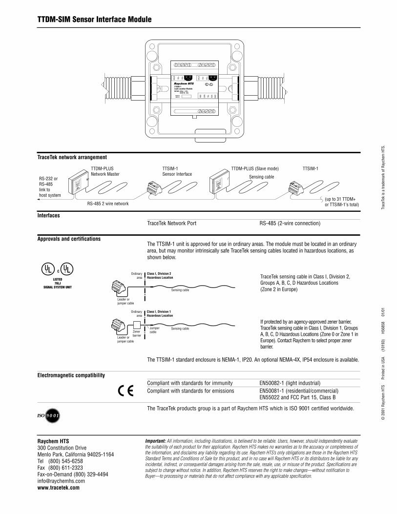
InterfacesTraceTek Network Port RS-485 (2-wire connection)
Approvals and certificationsThe TTSIM-1 unit is approved for use in ordinary areas. The module must be located in an ordinaryarea, but may monitor intrinsically safe TraceTek sensing cables located in hazardous locations, asshown below.
TraceTek sensing cable in Class I, Division 2,Groups A, B, C, D Hazardous Locations (Zone 2 in Europe)
If protected by an agency-approved zener barrier,TraceTek sensing cable in Class I, Division 1, GroupsA, B, C, D Hazardous Locations (Zone 0 or Zone 1 inEurope). Contact Raychem to select proper zenerbarrier.
The TTSIM-1 standard enclosure is NEMA-1, IP20. An optional NEMA-4X, IP54 enclosure is available.
Electromagnetic compatibilityCompliant with standards for immunity EN50082-1 (light industrial)Compliant with standards for emissions EN50081-1 (residential/commercial)
EN55022 and FCC Part 15, Class B
The TraceTek products group is a part of Raychem HTS which is ISO 9001 certified worldwide.
© 2
001
Rayc
hem
HTS
P
rinte
d in
USA
(
1019
3)
H56
858
0
1/01
Trac
eTek
is a
trad
emar
k of
Ray
chem
HTS
.
Important: All information, including illustrations, is believed to be reliable. Users, however, should independently evaluatethe suitability of each product for their application. Raychem HTS makes no warranties as to the accuracy or completeness ofthe information, and disclaims any liability regarding its use. Raychem HTS’s only obligations are those in the Raychem HTSStandard Terms and Conditions of Sale for this product, and in no case will Raychem HTS or its distributors be liable for anyincidental, indirect, or consequential damages arising from the sale, resale, use, or misuse of the product. Specifications aresubject to change without notice. In addition, Raychem HTS reserves the right to make changes—without notification toBuyer—to processing or materials that do not affect compliance with any applicable specification.
Raychem HTS 300 Constitution DriveMenlo Park, California 94025-1164Tel (800) 545-6258Fax (800) 611-2323Fax-on-Demand (800) [email protected]
SHLD
RS–
RS+ AC AC
RED
GRN
YEL
BLK
GND
TTSIM-1Leak Location ModuleRATING: 24Vac ±10%
50/60 Hz 3VA
NetworkAddress
SHLD
RS–
RS+ AC AC
TTDM-SIM Sensor Interface Module
Sensing cable
Leader or jumper cable
Ordinaryarea
Class I, Division 2Hazardous Location
SHLD
RS–
RS+AC
AC
RED
GRN
YEL
BLK
GND
TTSIM-1Leak Location Module
RATING: 24Vac ±10%
50/60 Hz 3VA
NetworkAddress SHLD
RS–
RS+AC
AC
Class I, Division 1Hazardous Location
Sensing cableJumpercable
Leader or jumper cable
Ordinaryarea
Zener barrier
SHLD
RS–
RS+AC
AC
RED
GRN
YEL
BLK
GND
TTSIM-1Leak Location Module
RATING: 24Vac ±10%
50/60 Hz 3VA
NetworkAddress SHLD
RS–
RS+AC
AC
R RC
LISTED76LJ
SIGNAL SYSTEM UNIT
TTDM-PLUSNetwork Master
TTSIM-1Sensor Interface
TTDM-PLUS (Slave mode) TTSIM-1
Sensing cable
(up to 31 TTDM+or TTSIM-1’s total)RS-485 2 wire network
RS-232 or RS-485link to host system
SHLD
RS–
RS+AC
AC
RED
GRN
YEL
BLKGND
TTSIM-1Leak Location Module
RATING: 24Vac ±10%
50/60 Hz3VA
NetworkAddress
SHLD
RS–
RS+AC
AC
SHLD
RS–
RS+AC
AC
RED
GRN
YEL
BLKGND
TTSIM-1Leak Location Module
RATING: 24Vac ±10%
50/60 Hz3VA
NetworkAddress
SHLD
RS–
RS+AC
AC
TraceTek network arrangement
9 0 01ISO
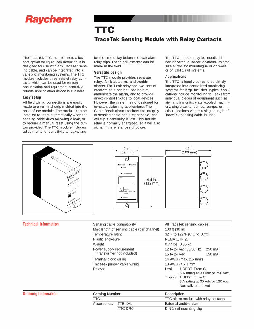
RTTCTraceTek Sensing Module with Relay Contacts
2 in.(52 mm)
4.4 in.(112 mm)
4.2 in.(106 mm)
IDENT:
LEAK
CABLE BREAK
RESET
LEAK DETECTOR
RELAY
POWER
TTC
Raychem TraceTek
The TraceTek TTC module offers a lowcost option for liquid leak detection. It isdesigned for use with any TraceTek sens-ing cable, and can be integrated into avariety of monitoring systems. The TTCmodule includes three sets of relay con-tacts which can be used for remoteannunciation and equipment control. Aremote annunciation device is available.
Easy setupAll field wiring connections are easilymade to a terminal strip molded into thebase of the module. The module can beinstalled to reset automatically when thesensing cable dries following a leak, orto require a manual reset using the but-ton provided. The TTC module includesadjustments for sensitivity to leaks, and
for the time delay before the leak alarmrelay trips. These adjustments can bemade in the field.
Versatile designThe TTC module provides separaterelays for leak alarms and troublealarms. The Leak relay has two sets ofcontacts so it can be used both toannunciate the alarm, and to providedirect control linkage to local devices.However, the system is not designed forconstant switching applications. TheCable Break alarm monitors the integrityof sensing cable and jumper cable, andwill trip if continuity is lost. This troublerelay is normally energized, so it will alsosignal if there is a loss of power.
The TTC module may be installed innon-hazardous indoor locations. Its smallsize allows for mounting in or on walls,or on DIN 1 rail systems.
ApplicationsThe TTC is ideally suited to be simplyintegrated into centralized monitoringsystems for large facilities. Typical appli-cations include monitoring for leaks fromindividual pieces of equipment such asair-handling units, water-cooled machin-ery, single tanks, pumps, sumps, orother locations where a single length ofTraceTek sensing cable is used.
Technical Information Sensing cable compatibility All TraceTek sensing cablesMax length of sensing cable (per channel) 100 ft (30 m)Temperature rating 32°F to 122°F (0°C to 50°C)Plastic enclosure NEMA 1, IP 20Weight 0.77 lbs (0.35 kg)Power supply requirement 12 to 24 Vac; 50/60 Hz 250 mA
(transformer not included) 15 to 24 Vdc 150 mATerminal block wiring 14 AWG (max. 2.5 mm2)TraceTek jumper cable wiring 18 AWG (4 x 1 mm2)Relays Leak 1 DPDT, Form C
5 A rating at 30 Vdc or 250 VacTrouble 1 SPDT, Form C
5 A rating at 30 Vdc or 120 Vac Normally energized
Ordering Information Catalog Number DescriptionTTC-1 TTC alarm module with relay contactsAccessories: TTE-XAL External audible alarm
TTC-DRC DIN 1 rail mounting clip
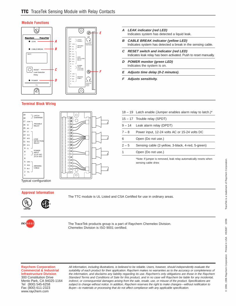
©19
90,
1996
Ray
chem
Cor
pora
tion
P
rinte
d in
US
A
H53
587
10
/96
T
race
Tek
is a
tra
dem
ark
of R
aych
em C
orpo
ratio
n.
All information, including illustrations, is believed to be reliable. Users, however, should independently evaluate thesuitability of each product for their application. Raychem makes no warranties as to the accuracy or completeness ofthe information, and disclaims any liability regarding its use. Raychem’s only obligations are those in the RaychemStandard Terms and Conditions of Sale for this product, and in no case will Raychem be liable for any incidental,indirect, or consequential damages arising from the sale, resale, use, or misuse of the product. Specifications aresubject to change without notice. In addition, Raychem reserves the right to make changes—without notification toBuyer—to materials or processing that do not affect compliance with any applicable specification.
Raychem CorporationCommercial & IndustrialInfrastructure Division300 Constitution DriveMenlo Park, CA 94025-1164Tel (800) 545-6258Fax (800) 611-2323 www.raychem.com
TTC TraceTek Sensing Module with Relay Contacts
The TraceTek products group is a part of Raychem Chemelex Division.Chemelex Division is ISO 9001 certified.
R
LISTED
9 0 01ISO
Approval Information The TTC module is UL Listed and CSA Certified for use in ordinary areas.
A LEAK indicator (red LED)Indicates system has detected a liquid leak.
B CABLE BREAK indicator (yellow LED)Indicates system has detected a break in the sensing cable.
C RESET switch and indicator (red LED) Indicates leak relay has been activated. Push to reset manually.
D POWER monitor (green LED)Indicates the system is on.
E Adjusts time delay (0-2 minutes).
F Adjusts sensitivity.
IDENT:
LEAK
CABLE BREAK
RESET
Leak Detection
Relay
POWER
TTC
Raychem TraceTek
COM
NC
NO
C2
NC2
NO2
NO1
NC1
C1
GRN
RED
BLK
YEL
19
18
17
16
15
14
13
12
11
10
9
8
7
6
5
4
3
2
1
LATCHENABLE
TROUBLERELAY
LEAKDETECTIONRELAY
POWERINPUT12-24 VAC15-24 VDC
SENSINGCABLE
INCREASETIME DELAY
0 2 MIN
1 MIN
INCREASESENSI-TIVITY
LOW HIGH
A
B
C
D
F
E
18 – 19 Latch enable (Jumper enables alarm relay to latch.)*
15 – 17 Trouble relay (SPDT)
9 – 14 Leak alarm relay (DPDT)
7 – 8 Power input, 12-24 volts AC or 15-24 volts DC
6 Open (Do not use.)
2 – 5 Sensing cable (2-yellow, 3-black, 4-red, 5-green)
1 Open (Do not use.)
*Note: If jumper is removed, leak relay automatically resets whensensing cable dries
Typical configuration
1918
1716
1514
1312
1110
98
76
54
32
1
COM
NC
NO
C2
NC2
NO2
NO1
NC1
C1
GRN
RED
BLK
YEL
19
18
17
16
15
14
13
12
11
10
9
8
7
6
5
4
3
2
1
LATCHOVERRIDE
TROUBLERELAY
LEAKDETECTIONRELAY
POWERINPUT12-24 VAC15-24 VDC
SENSINGCABLE
Terminal Block Wiring
Module Functions
®
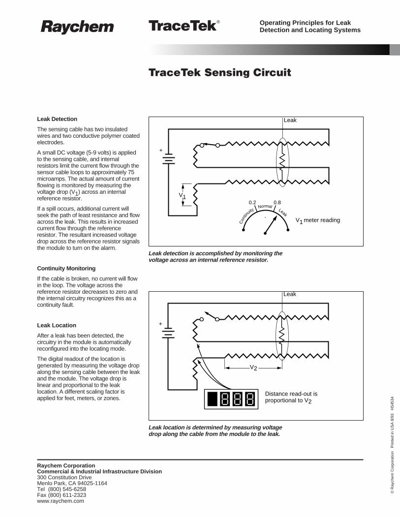
R TraceTek®
TraceTek Sensing Circuit
Leak Detection
The sensing cable has two insulatedwires and two conductive polymer coatedelectrodes.
A small DC voltage (5-9 volts) is appliedto the sensing cable, and internalresistors limit the current flow through thesensor cable loops to approximately 75microamps. The actual amount of currentflowing is monitored by measuring thevoltage drop (V1) across an internalreference resistor.
If a spill occurs, additional current willseek the path of least resistance and flowacross the leak. This results in increasedcurrent flow through the referenceresistor. The resultant increased voltagedrop across the reference resistor signalsthe module to turn on the alarm.
Continuity Monitoring
If the cable is broken, no current will flowin the loop. The voltage across thereference resistor decreases to zero andthe internal circuitry recognizes this as acontinuity fault.
Leak Location
After a leak has been detected, thecircuitry in the module is automaticallyreconfigured into the locating mode.
The digital readout of the location isgenerated by measuring the voltage dropalong the sensing cable between the leakand the module. The voltage drop islinear and proportional to the leaklocation. A different scaling factor isapplied for feet, meters, or zones.
Leak
V10.2
+
V1 meter reading
0.8
Con
tin
uityNormal
Leak
Leak
V2
Distance read-out isproportional to V2
+
Raychem CorporationCommercial & Industrial Infrastructure Division300 Constitution DriveMenlo Park, CA 94025-1164Tel (800) 545-6258Fax (800) 611-2323 www.raychem.com
©R
aych
em C
orpo
ratio
n P
rinte
d in
US
A 8
/93
H54
534
Leak detection is accomplished by monitoring thevoltage across an internal reference resistor.
Leak location is determined by measuring voltagedrop along the cable from the module to the leak.
Operating Principles for LeakDetection and Locating Systems
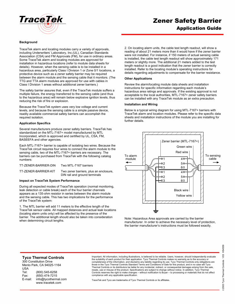
Zener Safety Barrier Application Guide
Background TraceTek alarm and locating modules carry a variety of approvals, including Underwriters’ Laboratory, Inc.(UL), Canadian Standards Association (CSA) and FM Approvals (FM), for use in ordinary areas. Some TraceTek alarm and locating modules are approved for installation in hazardous locations (refer to module data sheets for details). However, when the sensing cable is to be installed in a hazardous area, particularly Class I Division 1 or Zone 0/1 locations, a protective device such as a zener safety barrier may be required between the alarm module and the sensing cable that it monitors. (The TTG and TTA alarm modules are approved for use with cables in Class I Division 1 areas without additional zener barriers.)
The safety barrier assures that, even if the TraceTek module suffers a multiple failure, the energy transferred to the sensing cable (and thus to the hazardous area) will remain below explosive ignition levels, thus reducing the risk of fire or explosion.
Because the TraceTek system uses very low voltage and current levels, and because the sensing cable is a simple passive device, readily available commercial safety barriers can accomplish the required isolation.
Application Specifics
Several manufacturers produce zener safety barriers. TraceTek has standardized on the MTL-7167+ model manufactured by MTL Incorporated, which is approved and certified by UL, CSA, FM, BASEEFA and other agencies.
Each MTL-7167+ barrier is capable of isolating two wires. Because the TraceTek circuit requires four wires to connect the alarm module to the sensing cable, two of the MTL-7167+ barriers are necessary. The barriers can be purchased from TraceTek with the following catalog numbers:
TT-ZENER-BARRIER-DIN Two MTL-7167 barriers
TT-ZENER-BARRIER-KIT Two zener barriers, plus an enclosure, DIN rail and ground terminals
Impact on TraceTek System Performance
During all expected modes of TraceTek operation (normal monitoring, leak detection or cable break) each of the four barrier channels appears as a 135-ohm resistor in series between the alarm module and the sensing cable. This has two implications for the performance of the TraceTek system:
1. The MTL barrier will add 11 meters to the effective length of the TraceTek sensor cable. All mapped distances and actual leak locations (locating alarm units only) will be affected by the presence of the barrier. The additional length should also be taken into consideration when determining circuit lengths.
2. On locating alarm units, the cable test length readout, will show a reading of about 21 meters more than it would have if the zener barrier were not installed. For instance, if 150 meters of actual sensing cable is installed, the cable test length readout will show approximately 171 meters or slightly more. The additional 21 meters added to the test length readout is a good indication that the zener barrier is correctly installed. Refer to the locating module’s operating instructions for details regarding adjustments to compensate for the barrier resistance.
Other Applications
Review the alarm/locating module data sheets and installation instructions for specific information regarding each module’s hazardous area ratings and approvals. If the existing approval is not acceptable to the local authorities, MTL-7167+ zener safety barriers can be installed with any TraceTek module as an extra precaution.
Installation and Wiring
Below is a typical wiring diagram for using MTL-7167+ barriers with TraceTek alarm and location modules. Please refer to the specific data sheets and installation instructions of the module you are installing for further details.
12
12
Red wire
Green wire
Yellow wire
Black wire
Zener barrier (MTL-7167+)
To alarmmodule
To sensingcable4
5
45
3 6
3 6
Note: Hazardous Area approvals are carried by the barrier manufacturer. In order to achieve the necessary level of protection, the barrier manufacturer’s instructions must be followed exactly.
Tyco Thermal Controls 300 Constitution Drive Menlo Park, CA 94025-1164 USA Tel: (800) 545-6258 Fax: (650) 474-7215 E-mail: [email protected] www.tracetek.com
Important: All information, including illustrations, is believed to be reliable. Users, however, should independently evaluate the suitability of each product for their application. Tyco Thermal Controls makes no warranty as to the accuracy or completeness of the information, and disclaims any liability regarding its use. Tyco Thermal Controls only obligations are those in the Tyco Thermal Controls Standard Terms and Conditions of Sale for this product, and in no case will Tyco Thermal Controls or its distributors be liable for any incidental, indirect, or consequential damages arising from the sale, resale, use or misuse of the product. Specifications are subject to change without notice. In addition, Tyco Thermal Controls reserves the right to make changes – without notification to Buyer – to processing or materials that do not affect compliance with any applicable specification.
TraceTek and Tyco are trademarks of Tyco Thermal Controls or its affiliates.
20
03 T
yco
Ther
mal
Con
trols
1/0
3 H
5455
9