Embed Size (px)
Citation preview
""H
Technical Report
R 834Sponsored by
NAVAL FACILITIES ENGINEERING COMMAND
February 1976
CIVIL ENGINEERING LABORATORYNaval Construction Battalion Center
Port Hueneme, California 93043
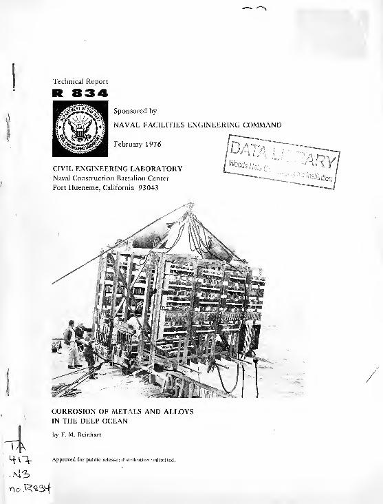
CORROSION OF METALS AND ALLOYSIN THE DEEP OCEAN
by F. M. Reinhart
*-+ \ _L. Approved for public release; distribution unlimited.


Unclassified
SECURITY CLASSIFICATION OF THIS PAGE (When Data :meredj
REPORT DOCUMENTATION PAGE READ INSTRUCTIONSBEFORE COMPLETING FORM
1. REPORT NUMBER
TR-8 34
2. GOVT ACCESSION NO.
DN 244098
3. RECIPIENT'S CATALOG NUMBER
4. TITLE (and Subtitle)
CORROSION OF METALS AND ALLOYS IN THEDEEP OCEAN
5. TYPE OF REPORT a PERIOD COVERED
Final; Oct 1961 to Jun 1974
6- PERFORMING ORG. REPORT NUMBER
7. AUTHORfsJ
F. M. Reinhart
8 CONTRACT OR GRANT NUMBER^)
9. PERFORMING ORGANIZATION NAME AND ADDRESSCivil Engineering Laboratory
Naval Construction Battalion Center
Port Hueneme, California 93043
10. PROGRAM ELEMENT. PROJECT. TASKAREA & WORK UNIT NUMBERS
62759N; YF53. 535.005.01.013
II. CONTROLLING OFFICE NAME AND ADDRESS
Naval Facilities Engineering CommandAlexandria, Virginia 22332
12. REPORT DATE
February 197613. NUMBER OF PAGES265
U MONITORING AGENCY NAME ft A0DRESSr"i7 dilterent trom Controlling Otfire) 15 SECURITY CLASS, (o! this report)
Unclassified
ISfl. DECLASSIFICATION DOWNGRADINGSCHEDULE
16. DISTRIBUTION STATEMENT (ol this Report)
Approved for public release; distribution unlimited.
17. DISTRIBUTION STATEMENT (0/ tor obstruct entered in Block 20. it different Iron, Report)
la. SUPPLEMENTARY NOTES
IS. KEY WORDS fConlmue on reverse side it necessary and identity by block number)
Corrosion, seawater, deep ocean, steels, cast irons, stainless steels, copper, nickel, aluminum,
titanium, miscellaneous alloys and wire ropes, effects of duration, depth and oxygen
concentration, stress corrosion.
Between 1960 and 1970, about 20,000 specimens of 475 alloys were exposed in the
seawater in the Pacific Ocean in order to conduct a program on the effects of deep-ocean
environments on materials. The test specimens included steels, cast irons, stainless steels,
copper, nickel, aluminum, titanium, miscellaneous alloys, and wire ropes. They were exposed
at the surface and at nominal depths of 2,500 and 6,000 feet for periods of time varying
continued
DD | jan 73 1473 EDITION OF I NOV 65 IS OBSOLETEUnclassified
SECURITY CLASSIFICATION OF THIS PAGE (OTien Dola Entered)
MBL/WHOI
0301 DOMOlfiS 7
Unclassified
SECURITY CLASSIFICATION OF THIS PAGEfHTien Data Entered)
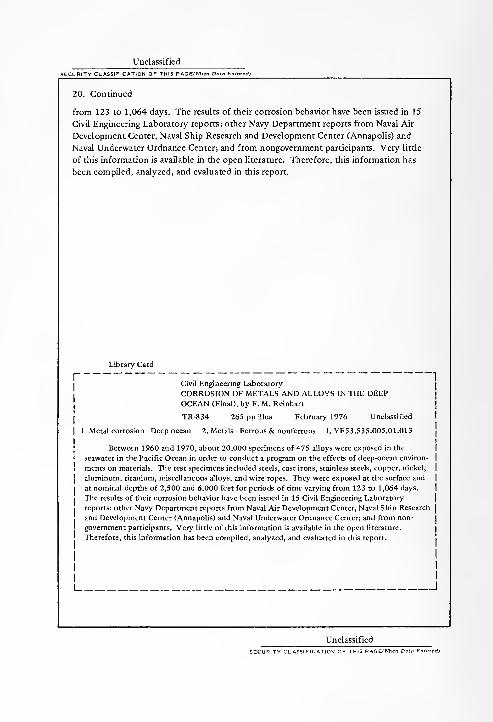
20. Continued
from 123 to 1,064 days. The results of their corrosion behavior have been issued in 15
Civil Engineering Laboratory reports; other Navy Department reports from Naval Air
Development Center, Naval Ship Research and Development Center (Annapolis) and
Naval Underwater Ordnance Center; and from nongovernment participants. Very little
of this information is available in the open literature. Therefore, this information has
been compiled, analyzed, and evaluated in this report.
Library Card
Civil Engineering Laboratory
CORROSION OF METALS AND ALLOYS IN THE DEEPOCEAN (Final), by F. M. Reinhart
TR-834 265 pp Ulus February 1976 Unclassified
1. Metal corrosion—Deep ocean 2. Metals— Ferrous & nonferrous I. YF53.535.005.01.013
Between 1960 and 1970, about 20,000 specimens of 475 alloys were exposed in the
seawater in the Pacific Ocean in order to conduct a program on the effects of deep-ocean environ-
ments on materials. The test specimens included steels, cast irons, stainless steels, copper, nickel,
aluminum, titanium, miscellaneous alloys, and wire ropes. They were exposed at the surface and
at nominal depths of 2,500 and 6,000 feet for periods of time varying from 123 to 1,064 days.
The results of their corrosion behavior have been issued in 15 Civil Engineering Laboratory
reports; other Navy Department reports from Naval Air Development Center, Naval Ship Research
and Development Center (Annapolis) and Naval Underwater Ordnance Center; and from non-
government participants. Very litde of this information is available in the open literature.
Therefore, this information has been compiled, analyzed, and evaluated in this report.
1 I
Unclassified
ASSIFICATION OF THIS P AGEfTOen Da
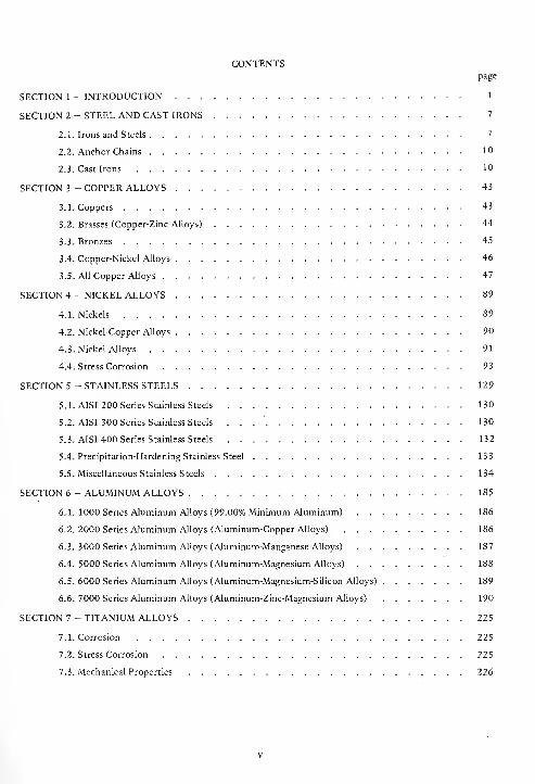
CONTENTSpage
SECTION 1 - INTRODUCTION 1
SECTION 2 - STEEL AND CAST IRONS 7
2.1. Irons and Steels . 7
2.2. Anchor Chains 10
2.3. Cast Irons 10
SECTION 3 - COPPER ALLOYS 43
3.1. Coppers 43
3.2. Brasses (Copper-Zinc Alloys) 44
3.3. Bronzes 45
3.4. Copper-Nickel Alloys 46
3.5. All Copper Alloys 47
SECTION 4 - NICKEL ALLOYS 89
4.1. Nickels 89
4.2. Nickel-Copper Alloys 90
4.3. Nickel Alloys 91
4.4. Stress Corrosion 93
SECTION 5 - STAINLESS STEELS 129
5.1. AISI 200 Series Stainless Steels 130
5.2. AISI 300 Series Stainless Steels . . 130
5.3. AISI 400 Series Stainless Steels 132
5.4. Precipitation-Hardening Stainless Steel 133
5.5. Miscellaneous Stainless Steels 134
SECTION 6 - ALUMINUM ALLOYS 185
6.1. 1000 Series Aluminum Alloys (99.00% Minimum Aluminum) 186
6.2. 2000 Series Aluminum Alloys (Aluminum-Copper Alloys) 186
6.3. 3000 Series Aluminum Alloys (Aluminum-Manganese Alloys) 187
6.4. 5000 Series Aluminum Alloys (Aluminum-Magnesium Alloys) 188
6.5. 6000 Series Aluminum Alloys (Aluminum-Magnesium-Silicon Alloys) 189
6.6. 7000 Series Aluminum Alloys (Aluminum-Zinc-Magnesium Alloys) 190
SECTION 7 - TITANIUM ALLOYS 225
7.1. Corrosion 225
7.2. Stress Corrosion 225
7.3. Mechanical Properties 226
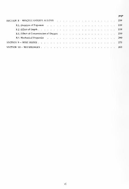
page
SECTION 8 - MISCELLANEOUS ALLOYS 239
8.1. Duration of Exposure 239
8.2. Effect of Depth 239
8.3. Effect of Concentration of Oxygen 239
8.4. Mechanical Properties 240
SECTION 9 - WIRE ROPES 253
SECTION 10 - REFERENCES 263

SECTION 1
INTRODUCTION
Between 1962 and 1970 the Civil Engineering
Laboratory, Naval Construction Battalion Center,
Port Hueneme, California, exposed approximately
20,000 specimens of about 475 different alloys in the
Pacific Ocean. These specimens were exposed at the
surface and at nominal depths of 2,500 and 6,000
feet for periods of time varying from 123 to 1,064
days.
The purpose of these exposures was to provide
the Naval Facilities Engineering Command(NAVFAC) with information on the deterioration of
materials in deep-ocean environments. Such informa-
tion was needed to improve techniques, to develop
new techniques pertaining to naval material, and to
support the increasing interest in the deep ocean as an
operating environment.
The Naval Facilities Engineering Command is
charged with the responsibility for the construction
and maintenance of all fixed Naval facilities; hence,
the construction and maintenance of Naval structures
at depths in the oceans are but one facet of its overall
responsibility. Fundamental to the design, construc-
tion, maintenance, and operation of structures and
their related facilities is information on the deteriora-
tion of materials in a particular environment. Since
there was very little published information on the
behavior of construction materials in deep-ocean
environments, this program was initiated in 1960 to
obtain such information.
In-situ testing was chosen because it is not
possible to duplicate all the variables and the changes
in these variables that prevail in any one environment
or location. A test site was considered suitable if the
circulation (currents), sedimentation, and bottom
conditions were representative of open ocean condi-
tions: (1) the bottom should be reasonably flat, (2)
the site should be open and not located in an area of
restricted circulation, such as a silled basin, (3) the
site should be reasonably close to Port Hueneme for
ship operations, and (4) the site should be within the
operating range of the more precise navigating and
locating techniques.
A Pacific Ocean site meeting these requirements
was selected at a nominal depth of 6,000 feet. The
ocean bottom at this site is relatively flat in a broad
submarine valley southwest of San Miguel Island,
California; it is readily accessible to the Civil Engi-
neering Laboratory; and it is subject to the effects of
ocean currents. This site, designated Test Site I, is
approximately 81 nautical miles southwest of Port
Hueneme, latitude 33°44'N, longitude 120°45'W.
Oceanographic data collected between 1961 and
1963 [1,2] show the presence of an oxygen mini-
mum zone at depths between 2,000 and 3,000 feet.
This minimum oxygen zone was present at all sites
investigated when the ocean floor was at depths
varying between 2,000 and 13,000 feet.
It is well known that the corrosion rates of many
materials (e.g., steels) are affected by the concen-
tration of oxygen in the environment. Because of
this, it was decided to establish a second test site,
Test Site II, in this minimum oxygen concentration
zone where, it was thought, much pertinent informa-
tion could be obtained. Test Site II (nominal depth of
2,500 feet) is 75 nautical miles west of Port Hue-
neme, latitude 34°06'N, longitude 120°42'W.
The oceanographic investigations by the Civil
Engineering Laboratory also disclosed that the ocean
floor at these sites is rather firm and was charac-
terized as sandy, green cohesive mud (partially
glauconite) with some rocks. Biological cultures of
these bottom sediments showed the presence of
sulfate-reducing bacteria in at least the first 6 inches
of sediment.
In order to determine the differences between the
corrosiveness of seawater at depths and at the surface
in the Pacific Ocean, it is desirable to compare
deep-ocean corrosion data with surface immersion
data. Since surface data from the Pacific Ocean in the
vicinity of Port Hueneme were not available in the
literature for most of the alloys exposed at depths in
the Pacific Ocean, it was decided to establish a sur-
face exposure site to obtain this information. There-
fore, a third site, Test Site V, was established at the
Naval Pacific Missile Range, Point Mugu, California,
latitude 34°06'N, longitude 119°07'W. Test Site V is
about 10 miles east of Port Hueneme.
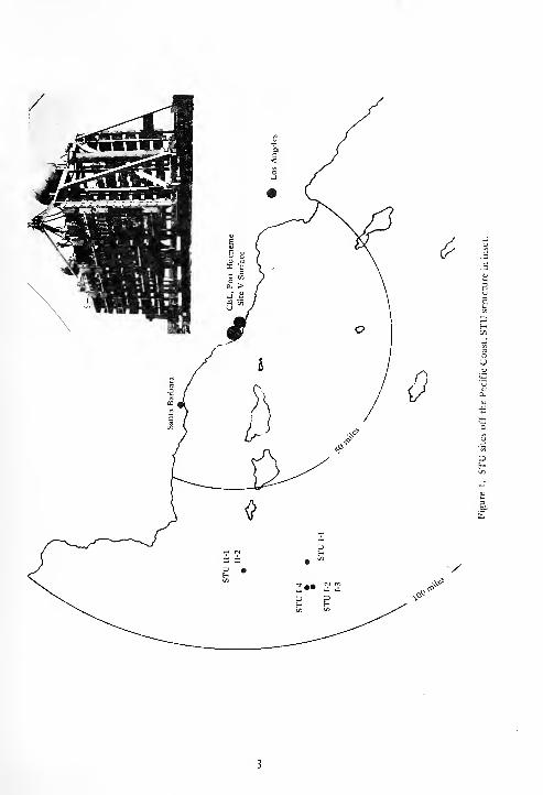
The specific geographical locations of the test
sites and the average characteristics of the seawater
10 feet above the ocean floor at these sites are given
in Table 1. Their positions relative to the California
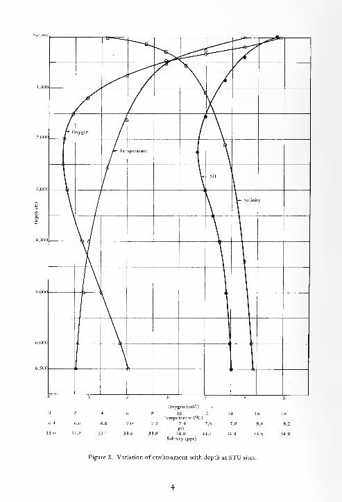
coast are shown in Figure 1. The variation of the
temperature, pH, salinity and oxygen content of the
seawater with depth at the STU sites is shown in
Figure 2.
Other naval activities were invited to participate
in this program and, if possible, to contribute to the
funding. From 1962 to 1966 the Naval Air Systems
Command supplied funds for partial support of the
program. Navy contractors and other companies also
participated in this program. The participants are
listed in Table 2 as well as those who evaluated the
materials and whether or not the evaluators, other
than CEL, supplied CEL with the results of their
evaluations.
This report presents the performance data
obtained by CEL and other participants from the sea-
water exposures at the sites given in Table 1. Theperformance of the various materials as supported bythis data is also discussed.
a
/^
2,000r °xygen
li
f~~Teniperature
pHi
\V-- Salinity
Q
\1
\1
5,0001
1
1
1
6.4
33.0
Oxygen (ml/1)
6 8 10Temperature (°C)
7.0 7.2 7.4pH
3.6 3 3.8 34.0 3
Salinity (ppt)
8.0
34.6
Figure 2. Variation of environment with depth at STU sites.

Table 1. Exposure Site Locations and Seawater Characteristics
Site Latitude Longitude Depth Exposure Temperature Oxygen SalinitypH
Average
No. N W (ft) (day) (°C) (ml/1) (ppt)(knot)
1-1 33°46' 120°37' 5,300 1,064 2.6 1.2 34.51 7.5 0.03
1-2 33°44' 120°45' 5,640 751 2.3 1.3 34.51 7.6 0.03
1-3 33°44' 120°45' 5,640 123 2.3 1.3 34.51 7.6 0.03
1-4 3 3°46' 120°46' 6,780 403 2.2 1.6 34.40 7.7 0.03
1-5 33°51' 120°35' 5,900 189 2.3 1.6 34.6 7.4 0.03
II-l 34°06' 120°42' 2,340 197 5.0 0.4 34.36 7.5 0.06
II-2 34°06' 120°42' 2,370 402 5.0 0.4 34.36 7.5 0.06
V 34°06' 119°07' 5 181-763 12-19 3.9-6.6 33.51 8.1 variable
Table 2. Participants in Test Program
Materials Report
Name Evaluated Submitted
By to CEL
Aerojet-General Corp. AGC no
Aluminum Company of America CEL -
Allegheny Ludlum Steel Corp. CEL -
American Chain and Cable Co. CEL -
American Steel and Wire Div., U.S.S. CEL -
Anaconda American Brass Co. CEL -
Anaconda Wire and Cable Co. AWCC yes
Armco Steel Corp. CEL -
Baldt Anchor Chain and Forge Div., Boston Metals Co. CEL -
Bell Telephone Laboratories BTL yes
Bethlehem Steel Co. CEL -
Boeing Co. Boeing yes
Brush Beryllium Co. CEL --
Carpenter Steel Co. CEL -
E. I. Dupont Co. CEL -
Elgiloy Co. CEL -
Fansteel Metallurgical Corp. CEL -
Goodyear Aerospace Corp. GAC yes
Haynes Stellite Div., Cabot Corp. CEL -
Hooker Chemical Corp. CEL -
.Continued
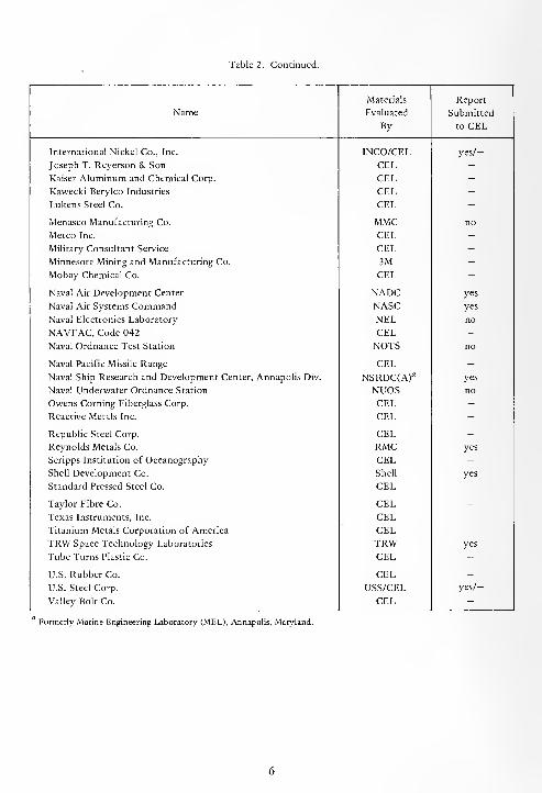
Table 2. Continued.
Materials Report
Name Evaluated Submitted
By to CEL
International Nickel Co., Inc. INCO/CEL yes/—
Joseph T. Reyerson & Son CEL -
Kaiser Aluminum and Chemical Corp. CEL -Kawecki Berylco Industries CEL -
Lukens Steel Co. CEL -
Menasco Manufacturing Co. MMC no
Metco Inc. CEL -
Military Consultant Service CEL -
Minnesota Mining and Manufacturing Co. 3M -
Mobay Chemical Co. CEL -
Naval Air Development Center NADC yes
Naval Air Systems Command NASC yes
Naval Electronics Laboratory NEL no
NAVFAC, Code 042 CEL -
Naval Ordnance Test Station NOTS no
Naval Pacific Missile Range CEL -
Naval Ship Research and Development Center, Annapolis Div. NSRDC(A)a yes
Naval Underwater Ordnance Station NUOS no
Owens Corning Fiberglass Corp. CEL -
Reactive Metals Inc. CEL -
Republic Steel Corp. CEL -
Reynolds Metals Co. RMC yes
Scripps Institution of Oceanography CEL -
Shell Development Co. Shell yes
Standard Pressed Steel Co. CEL -
Taylor Fibre Co. CEL -
Texas Instruments, Inc. CEL -
Titanium Metals Corporation of America CEL -
TRW Space Technology Laboratories TRW yes
Tube Turns Plastic Co. CEL -
U.S. Rubber Co. CEL -
U.S. Steel Corp. USS/CEL yes/—
Valley Bolt Co. CEL -
Formerly Marine Engineering Laboratory (MEL), Annapolis, Maryland.

SECTION 2
STEEL AND CAST IRONS
The data discussed in this section were obtained
from the reports given in References 3 through 19.
The chemical compositions of the alloys are given in
Table 3; their surface conditions and heat treatments,
if any, are given in Table 4.
The corrosion rates and types of corrosion of all
the alloys are given in Table 5. Inorganic coatings
were applied to some steels to evaluate their protec-
tive qualities. These coatings and their conditions are
given in Table 6. Steels that were exposed in a
stressed condition to determine their susceptibility to
stress corrosion cracking are given in Table 7.
The effects of corrosion on the mechanical
properties of many of the alloys were determined
after various periods of exposure; these results are
given in Table 8.
Water near the surface in the open sea is quite
uniform in its composition throughout the oceans
[20] ; therefore, the corrosion rates of steels exposed
under similar conditions in clean seawater should be
comparable. The results of many investigations on the
corrosion of structural steels in surface seawater at
many locations throughout the world show that after
a short period of exposure the corrosion rates are
constant and amount to between 3 and 5 mils per
year [21,22]. Factors which can cause differences in
corrosion rates outside these limits are variations in
marine fouling, contamination of the seawater near
the shorelines, variations in seawater velocity, and
differences in the surface water temperature.
2.1. IRONS AND STEELS
The corrosion rates of the irons; mild steels; high-
strength low-alloy steels; high-strength steels; other
alloy steels; and nickel alloy steels are given in Table
5. Analysis of the corrosion rates of these alloys
shows that for all practical purposes their corrosion
rates were comparable for any one duration of
exposure at any one depth or at the surface. There-
fore, these data were treated statistically to obtain
one median value for each time of exposure and each
depth. These average data values were used to plot
curves to show the general corrosion behavior to be
expected from these alloys with regard to duration of
exposure, depth in the ocean, and concentration of
oxygen in seawater.
2.1.1. Duration of Exposure
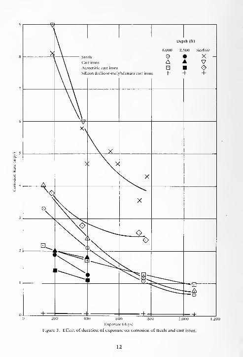
The effects of the duration of exposure on the
corrosion of steels in seawater at the surface and at
depth are shown in Figure 3. The corrosion rates of
the steels exposed in seawater at nominal depths of
2,500 and 6,000 feet in the Pacific Ocean decreased
with increasing duration of exposure and were con-
sistently lower than the surface corrosion rates by a
factor of approximately 3. The corrosion rates at the
2,500-foot depth also were lower than those at the
6,000-foot depth. The corrosion rates decreased
asymptotically with increasing duration of exposure
both at the surface and at the 6,000-foot depth.
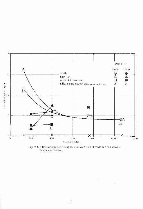
The performance of the steels when partially
embedded in the bottom sediments at the 2,500- and
6,000-foot depths is shown in Figure 4. Here, also,
the average corrosion rates of the steels at the
6,000-foot depth decreased asymptotically with
increasing duration of exposure. During the initial
exposures the steels corroded at faster rates in sea-
water than in the bottom sediments at the 6,000-foot
depth, but after approximately 2 years of exposure,
their average corrosion rates were approximately the
same as shown by comparing the curves in Figures 3
and 4. Here, also, the average corrosion rates at the
2,500-foot depth were lower than at the 6,000-foot
depth, but they increased with increasing duration of
exposure.
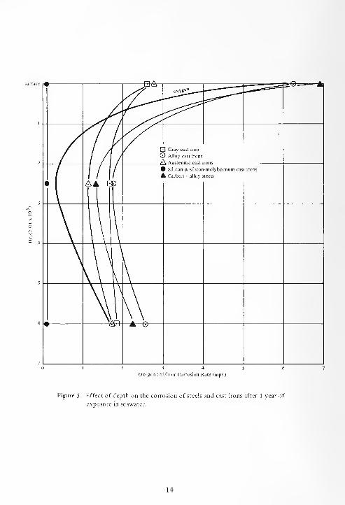
2.1.2. Depth
The effect of depth of exposure in seawater on
the average corrosion rates of the steels is shown in
Figure 5. The variation of the concentration of
oxygen in seawater with depth is also shown in Figure
5 for comparison purposes. The shape of the curve

for steels shows that corrosion of steels is not
affected by depth (pressure), at least to a depth of
6,000 feet (2,700 psi) for a period of 1 year of expo-
sure. The shape of this curve is practically identical to
that of the oxygen concentration curve. The identical
shape of these curves indicate that the concentration
of oxygen in seawater exerts a major influence on the
corrosion of steels in this environment.
2.1.3. Concentration of Oxygen
The effect of the variation in the concentration of
oxygen in seawater on the corrosion of steels after 1
year of exposure is shown in Figure 6. The curve for
the average corrosion rates of the steels after 1 year
of exposure versus the concentration of oxygen is a
straight line. This indicates that the corrosion of
steels in seawater is proportional to the concentration
of oxygen.
2.1.4. Nickel
The effect of the variation of the concentration
of nickel on the corrosion of steels is shown in Figure
7. Variations of from 1.5 to 9% in the nickel content
were ineffectual with respect to the corrosion of steel
both at the surface and at depth. However, the cor-
rosion rates in surface exposures were higher than at
depth by about a factor of 7.
2.1.5. Type of Corrosion
All the steel, except AISI Type 502, in general,
corroded uniformly except for some slight pitting in
surface seawater which was caused by fouling. The
corrosion rates of AISI Type 502 steel (5% Cr-0.5%
Mo) were erratic- and higher than those of the other
steels. This behavior is attributed to the broad,
shallow pitting and the severe crevice corrosion
caused by the chromium content of the steel.
2.1.6. Metallic Coatings
Zinc, aluminum, sprayed aluminum, titanium-
cadmium, cadmium, copper, and nickel-coated steel
specimens were exposed at depth.
A 1 oz/sq ft of zinc on galvanized steel sheet
exposed at a depth of 2,500 feet protected the steel
for from 3 to 4 months in the seawater and for about
7 months when partially embedded in the bottom
sediments.
A 1 oz/sq ft of aluminum on aluminized steel
sheet exposed at a depth of 2,500 feet protected the
steel for at least 1 3 months in the seawater and when
partially embedded in the bottom sediments.
A 6-mil-thick hot-sprayed aluminum coating over
steel, which had been subsequently primed and
sprayed with two coats of clear vinyl sealer, protected
the underlying steel from corroding for 1,064 days at
the 6,000-foot depth. After removal from exposure
the aluminum coating was dark gray and speckled
with pin-point size areas of white corrosion products.
Since no red rust was present, it is evident that this
coating would provide added protection to the steel
for an additional period of time, possibly another 3
years.
A titamium-cadmium coating on AISI 4130 steel
was completely sacrificed, and the underlying steel
was covered with a layer of red rust after 402 days of
exposure at a depth of 2,500 feet. Such a coating
would not provide satisfactory protection for sea-
water applications.
An electrolytically applied cadmium coating on
steels, both stressed and unstressed, did not provide
adequate protection for 1 year of exposure at depths
of 2,500 and 6,000 feet.
Electrolytically applied copper and nickel
coatings on steels, both stressed and unstressed, failed
within 6 months after exposure at the 2,500-foot
depth and caused galvanic corrosion of the underlying
steels.
2.1.7. Inorganic Coatings
A few steels were coated with selected paint
coatings to determine their performance at depths in
the Pacific Ocean. Table 6 shows the results of this
test.
The multicoat epoxy systems exhibited, in
general, satisfactory performance, while the multicoat
polyurethane system behaved erratically, varying
from cracked and blistered paint to no paint failures.
The single-coat, zinc-rich primer coating did not
afford satisfactory protection for a period of 6
months at a depth of 6,000 feet.
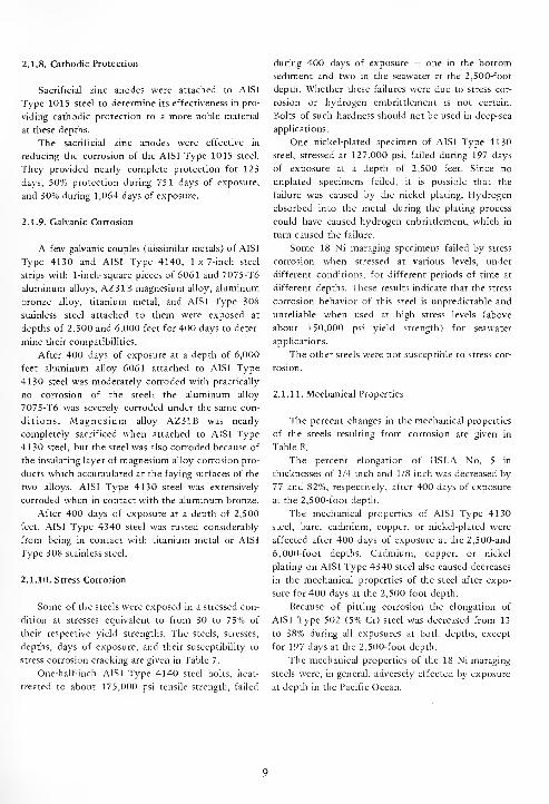
2.1.8. Cathodic Protection
Sacrificial zinc anodes were attached to AISI
Type 1015 steel to determine its effectiveness in pro-
viding cathodic protection to a more noble material
at these depths.
The sacrificial zinc anodes were effective in
reducing the corrosion of the AISI Type 1015 steel.
They provided nearly complete protection for 123
days, 50% protection during 75 1 days of exposure,
and 30% during 1,064 days of exposure.
2.1.9. Galvanic Corrosion
A few galvanic couples (dissimilar metals) of AISI
Type 4130 and AISI Type 4140, 1 x 7-inch steel
strips with 1-inch-square pieces of 6061 and 7075-T6
aluminum alloys, AZ31B magnesium alloy, aluminum
bronze alloy, titanium metal, and AISI Type 308
stainless steel attached to them were exposed at
depths of 2,500 and 6,000 feet for 400 days to deter-
mine their compatibilities.
After 400 days of exposure at a depth of 6,000
feet aluminum alloy 6061 attached to AISI Type
4130 steel was moderately corroded with practically
no corrosion of the steel; the aluminum alloy
7075-T6 was severely corroded under the same con-
ditions. Magnesium alloy AZ31B was nearly
completely sacrificed when attached to AISI Type
4130 steel, but the steel was also corroded because of
the insulating layer of magnesium alloy corrosion pro-
ducts which accumulated at the faying surfaces of the
two alloys. AISI Type 4130 steel was extensively
corroded when in contact with the aluminum bronze.
After 400 days of exposure at a depth of 2,500
feet, AISI Type 4340 steel was rusted considerably
from being in contact with titanium metal or AISI
Type 308 stainless steel.
2.1.10. Stress Corrosion
Some of the steels were exposed in a stressed con-
dition at stresses equivalent to from 30 to 75% of
their respective yield strengths. The steels, stresses,
depths, days of exposure, and their susceptibility to
stress corrosion cracking are given in Table 7.
One-half-inch AISI Type 4140 steel bolts, heat-
treated to about 175,000 psi tensile strength, failed
during 400 days of exposure — one in the bottom
sediment and two in the seawater at the 2,500-foot
depth. Whether these failures were due to stress cor-
rosion or hydrogen embrittlement is not certain.
Bolts of such hardness should not be used in deep-sea
applications.
One nickel-plated specimen of AISI Type 4130
steel, stressed at 127,000 psi, failed during 197 days
of exposure at a depth of 2,500 feet. Since no
unplated specimens failed, it is possible that the
failure was caused by the nickel plating. Hydrogen
absorbed into the metal during the plating process
could have caused hydrogen enbrittlement, which in
turn caused the failure.
Some 18 Ni maraging specimens failed by stress
corrosion when stressed at various levels, under
different conditions, for different periods of time at
different depths. These results indicate that the stress
corrosion behavior of this steel is unpredictable and
unreliable when used at high stress levels (above
about 150,000 psi yield strength) for seawater
applications.
The other steels were not susceptible to stress cor-
rosion.
2.1.11. Mechanical Properties
The percent changes in the mechanical properties
of the steels resulting from corrosion are given in
Table 8.
The percent elongation of HSLA No. 5 in
thicknesses of 1/4 inch and 1/8 inch was decreased by
77 and 82%, respectively, after 400 days of exposure
at the 2,500-foot depth.
The mechanical properties of AISI Type 4130
steel, bare, cadmium, copper, or nickel-plated were
affected after 400 days of exposure at the 2,500-and
6,000-foot depths. Cadmium, copper, or nickel
plating on AISI Type 4340 steel also caused decreases
in the mechanical properties of the steel after expo-
sure for 400 days at the 2,500-foot depth.
Because of pitting corrosion the elongation of
AISI Type 502 (5% Cr) steel was decreased from 13
to 38% during all exposures at both depths, except
for 197 days at the 2,500-foot depth.
The mechanical properties of the 18 Ni maraging
steels were, in general, adversely affected by exposure
at depth in the Pacific Ocean.
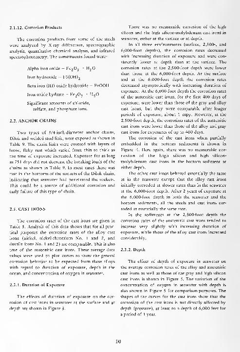
2.1.12. Corrosion Products
The corrosion products from some of the steels
were analyzed by X-ray diffraction, spectrographic
analysis, quantitative chemical analysis, and infrared
spectrophotometry. The constituents found were:
Alpha iron oxide — Fe2 3
H2
Iron hydroxide — F3(OH)2
Beta iron (III) oxide hydroxide — FeOOH
Iron oxide hydrate — Fe2 3
H2
Significant amounts of chloride,
sulfate, and phosphate ions.
2.2. ANCHOR CHAINS
Two types of 3/4-inch-diameter anchor chains,
Dilok and welded stud link, were exposed as shown in
Table 9. The chain links were covered with layers of
loose, flaky rust which varied from thin to thick as
the time of exposure increased. Exposure for as long
as 751 days did not decrease the breaking loads of the
chains as shown in Table 9. In most cases there was
rust in the bottoms of the sockets of the Dilok chain,
indicating that seawater had penetrated the sockets.
This could be a source of additional corrosion and
early failure of this type of chain.
2.3. CAST IRONS
The corrosion rates of the cast irons are given in
Table 5. Analysis of this data shows that for all prac-
tical purposes the corrosion rates of the alloy cast
irons (nickel, nickel-chromium No. 1 and 2, and
ductile irons No. 1 and 2) are comparable. This is also
true of the austenitic cast irons. These average data
values were used to plot curves to show the general
corrosion behavior to be expected from these alloys
with regard to duration of exposure, depth in the
ocean, and concentration of oxygen in seawater.
2.3.1. Duration of Exposure
The effects of duration of exposure on the cor-
rosion of cast irons in seawater at the surface and at
depth are shown in Figure 3.
There was no measurable corrosion of the high
silicon and the high silicon-molybdenum cast irons in
seawater, either at the surface or at depth.
In all three environments (surface, 2,500-, and
6,000-foot depths), the corrosion rates decreased
with increasing duration of exposure and were con-
sistently lower at depth than at the surface. The
corrosion rates at the 2,500-foot depth were lower
than those at the 6,000-foot depth. At the surface
and at the 6,000-foot depth the corrosion rates
decreased asymptotically with increasing duration of
exposure. At the 6,000-foot depth the corrosion rates
of the austenitic cast irons, for the first 400 days of
exposure, were lower than those of the gray and alloy
cast irons, but they were comparable after longer
periods of exposure, about 1 mpy. However, at the
2,500-foot depth, the corrosion rates of the austenitic
cast irons were lower than those of the alloy and gray
cast irons for exposures of up to 400 days.
The corrosion of the cast irons when partially
embedded in the bottom sediments is shown in
Figure 4. Here again, there was no measurable cor-
rosion of the high silicon and high silicon-
molybdenum cast irons in the bottom sediment at
either depth.
The other cast irons behaved essentially the same
as in the seawater except that the alloy cast irons
initially corroded at slower rates than in the seawater
at the 6,000-foot depth. After 2 years of exposure at
the 6,000-foot depth in both the seawater and the
bottom sediments, all the steels and cast irons cor-
roded at essentially the same rate.
In the sediments at the 2,500-foot depth the
corrosion rates of the austenitic cast irons tended to
increase very slightly with increasing duration of
exposure, while those of the alloy cast irons increased
considerably.
2.3.2. Depth
The effect of depth of exposure in seawater on
the average corrosion rates of the alloy and austenitic
cast irons as well as those of the gray and high silicon
cast irons is shown in Figure 5. The variation of the
concentration of oxygen in seawater with depth is
also shown in Figure 5 for comparison purposes. The
shapes of the curves for the cast irons show that the
corrosion of the cast irons is not directly affected by
depth (pressure), at least to a depth of 6,000 feet for
a period of 1 year.
10
2.3.3. Concentration of Oxygen
The effect of the variation in the concentration of
oxygen in seawater on the corrosion of cast irons
after 1 year of exposure is shown in Figure 6. The
curves for the average corrosion rates of the gray,
alloy, and austenitic cast irons versus the concentra-
tion of oxygen are essentially straight lines. This
indicates that the corrosion of the cast irons in sea-
water is proportional to the concentration of oxygen.
However, the different slopes of the curves indicate
different degrees of influence, the influence being
greatest on the alloy cast irons and least on the gray
cast irons. Oxygen exerted no influence on the cor-
rosion of high silicon or high silicon-molybdenum
cast irons.
2.3.4. Type of Corrosion
All the cast irons corroded uniformly both in the
seawater and in the bottom sediments. The high
silicon and high silicon-molybdenum cast irons were
uncorroded in any of the environments.
2.3.5. Mechanical Properties
The percent changes in the mechanical properties
of the cast irons due to exposure in seawater are given
in Table 8. The mechanical properties of the Type 4
austenitic cast iron were not affected by exposure
either at the surface or at the 2,500-foot depth. How-
ever, the mechanical properties of the D-2C austenitic
cast iron were significantly lowered. About 80% of
the surfaces of fracture of the D-2C specimens were
black in contrast to the gray surfaces of fracture of
unexposed specimens. Metallographic examinations
of polished cross sections of the D-2C alloy adjacent
to the surfaces of fracture showed that the alloy had
been attacked by selective interdendritic corrosion.
This selective corrosion was the cause of the decrease
in mechanical properties of the alloy.
11
200 400 800 1 ,000600
lixposurc (days)
Figure 3. Effect of duration of exposure on corrosion of steels and cast irons.
12
Depth (ft)
A 6,000 2,500
Steels O • _Cast irons A AAustenitic cast irons
Silicon & silicon-molybdenum cast irons X X
K
\\.iEl
r K T~ VJiA
I— G>A
1
4
. I1
]
a
x— / >v X ^600
'.xposurc (das)
1,000
Figure 4. Effect of duration of exposure on corrosion of steels and cast irons in
bottom sediments.
13
Oxygen (ml/I) or Corrosion Rate (mpy)
Figure 5. Effect of depth on the corrosion of steels and cast irons after 1 year of
exposure in seawater.
14

12 3 4 5
Oxygen (ml/1)
Figure 6. Effect of concentration of oxygen in seawater on the corrosion of steels
and cast irons after 1 year of exposure.
15

1
IJI
r-B-e1
ys,
6,000
feet
lays,
6,000
feet
ys,
2,500
feet
ys,
surface
a *
00
•a -o
O VO
•
m rrn;vfiW Ijy!/<J
II n $%t w
<> 30
•- F3$ :
(Xdui) ojny uoisojj(>3
16

a
un- w -+ -t it- * * * * * -t-
-+ <* *
<zz 5
w CI C2 d3
J O j J o
5
o J J -J J J J ij Jc
J o Jw c o o
uz
ouz
ouzW z w z z UJ w w UJ pa w tu w w z a w o zu u u u u u u u u u u u u u oa
£ JS . .
1t^ CM O
1
> V > u1
1
. . .
+ ON »o oo o o m o o
1 I 1 1 1
o o o
1 1 1 1 1 1
o o o o
1
00 f* 00
1
o1 1 1 1
CNI +1 1
o *o o o o o o o ,H o o *"*
-1 CO n rsi CM ,_, t^
1 1 I 1 1 1 1
o •4-1 1 1
*°i 1
,H o o o o o o o
CM rr> o "* in VO ON 00 IN ^o * rn T_) ou 1 1 I 1
o1
o1 1
vO t^ CO *1
c^
o o CM o T_l ,H 7-1 o o o o o o
•+ ,_, in * \o w ,_, IS * CO ^ Tt" r^. oo o o ON ON t^ q!
•* o ON
o o o CM CM CM o o o o o o ^ o
o 00 * rf<o m Tt- CO t^ o T)- n
c/: o ^ c CM CM * o 1 oo o o o o o o o o o o c o o o o o o o
CO + r^ o rt m in 00 o m in COcm cm rl CM CM
C/3 o o o o o o o o o o o o o 1 1
o o o o o o o o o o o o o o
* >o ^ o m * in o * o r^
o o o o o o o o o o c 1 o o 1 o 1 o oo o o o o o o o o o o o o o c o o o o o
^o o Tf o -\o vn
o o + f* ^ CM t^ CO TT- CM r^ ^oo o o o o o o o o o o o o o o o o o o o o o
CM •+ o <f> CO r^ r^. •+ o ^o1
1
o oo o o o o o o o o o o o o o
r
c ca
+ « o- .=: c o o m a 6 o o o o o o o o o o o£ <J -. o c o < < < <u z z z z z z z z z z z z z z z z00 rt *"" rt rt
n s s ss
< < < < < < < < < < < < < < <f <*
H H H -J -J -1 J «J J u -1 J J J J J _l _l _1on 00 on C/3 en on on t/1 en
< < < < < <j < < < Oh X ac X X X X X X X X X X X X X
17
au
NO <-» [V NO
<-> tn -r * S S * 00 s s J J J bo N+ JINCO
CNADCl
Boeing
1*-*
3O O
uz
J J j j J CO J J J J J g-J J O
CJCO Id w Id Id Si CO Id HI w u Id o Id Id ZU u CJ CJ u X (J (J u cj CJ CO CJ CJ
>+
S* < O Z --Z < < o z oa — —•£ 1 > > > - m O H < ^ < 00 > > > m en i cm > 1 „(-< P < 1 1 1 1
o CM CM rt in r^ (N O ii *• «H O m no O en o o o 0\ o * t- NO 00
O o o o o o o q CM CM CM •* O 1 O *1 ° o o o O O On i en od d d d d d d d d d d d d d d d d odd d d d d d d
CM O o ON in en mo
1 1 11 |
I 1
00 ON1 q 1
r^ q oq|
1U en m 00 * 00 00 r>." t^
o CO op
1 11 |
I 1 ||
1 1 I 1 1 1 11
CJ © d d
no CM X CM On r^ r^ o CO ^ oo m CMc
l
-i-1
't n+ * * On q I
r-~ 00 9 ">1
1
S d d d en en d d d d ,_t + * in +
NO in NO NO t^ *t en t-- en O ^1 q q in •+ CM c^
1 1 1 1 1 1 1
6 ^ d d in in d d CM d
o O en rH O * NO NO NO ,_ 00 CM r*.
NO O ON q CS en r^. On On 9 9 ,
2 6 CMl iX +
!2CM 00° 00 CM On On r> 00 CO 00 ' 1
CM t^t^ o On CM NO O H r~ NO CM <* NO
co 1 o q 1 O q q 1
o 1 1 1 1
d d d d d d d d d d d d d
o\ NO U-l in en in O en in * t^ oo o o O O ii O o o
CO 1 o o o o q O o o O o c 1 o o 1 1 1 1
d d d d d d d d d d d d d
00 en * i-~ in * NO in r*. in in00 * o o o o o o o O o O Oo o o o o o o o o o O o 1 o O 1 1 1 1
6 d d d d d d d d d d d d d
CO
C ON no CO 00 * t> ON On 00 NO o oNO CM r-~ oo o o o
1
o1 1 1 1
d d " d d d d d d d d d d d
CM CM* t-h CM o oo * 00 CM CM
UI
cm o o CM CM1 q o
1 1 1 1
d d d d d d d d d d d d d
OS bo 00 bo oo ooB C c c c c" 2 £ 'Eh §> '5b '5b '5b '5b
rt rt rt
dZ
d2
dz
" 5 CM<
en en TT m NO1 1 1 111
z< < < d d
Z ZdZ
dZ
d o"
Z ZdZ
dZ
dZ z Z Z z z z
co CO CO in CO CO » CO CO CO CO CO CO 00 00 00 00 00X X X X X X X X X X X X
a
a O O O p<z
td <U Z
* —
'
~-r oOSB n o o n o O n oh3
z <O o 3j
7 W° ° Jvj CJ -J
Ori <-> u u u u U u u u u U
j. z z z u - paz 2 z z z z z z z z z
, >1 1 1 1 1 1 i i
o
u
^ vO
o vO O
* vo m5 Cvl Cv1
1 1 1 1 1 1 1 1 1 1 1 1 1
o o o o O O rt rn m
N m .n ON + r* -t c-i vO Ov CO o00 00 t~- r~ rvi
1 1
VO ON1 1 1 1 1
r- o 00 Ov o (S r-H O r^
o o o c •+ in rt o o ,H N rvi <* IT. Cvl m o <N
<o VO <N _ CO +z r- o
. * vO VO ON 00 Cvl
1 o 00 Ov Ov i-i O rv] Ov"-1 *~* IN <N M N M N
r~
+ Ov -* O COX
1 1 1 cvi rvi 1m
| 1 1•* VO Ov N O « o CO
o o O in "-1 ,H rvi cs * * rt <N rvi '"l in in rrt CJ rvi *^
Cvl * O1 1 1 o
do 1
6o 1
d1 1 1
v> r^ o r~
1 1 1 oo"
o 1
dq 1
d1 1
d
O00 vn Tt" VO Ov * vo (S
s •+ 00 r~ o * in vo r-- 001 4d
* o VO in c~ Ov Ov rf
O o o o o o o o o o o ,H ^ o o o O O rvi o
o\£5 VO
1 1
o o-3- rn
o oo oo o
-t
o 1 1 1 1 1 1 1 I 4d
1 1 1 1 1rvi
1 1*
1
.
(M rn * 4
>, X >**"* (J H H r- H r- Q Q Q Q
Cv] oZ
oZ B E B E E E E E B
O O O O— 7 Z B B^ B
oB O c c
o o S tS <s M rt 333 3
o o-t
o o cs
8EO .a .a .a .a .a .a .a .a .a
f. 1/3 1/3
o o
t/3 1/3 <vo
1 <J y
o
1o oS S
E
3
B
3
E
3
E E
3 3
BEE3 3 3
E
3z z z
rn In ov < < < < < < Q U Z Z z Q Q 1/3 (/3 C/3 < < < < < < < < <
19
INCO
(3)
CEL
(4)
CEL
(4)
51 1 1
u 1 1 1
'- 1 1 1
« 1 1 1
u 1 1 1
z 1 1 1
X 1 1 1
c/:
8 *1 o.|
1
=o Xlog 1
d
|
o
61 iA 1
d
uin X
1-. g 1
o c
1
3g <-,
c ° £o rt
u -a g *b S .a
°
11 is< a <
S E S
20
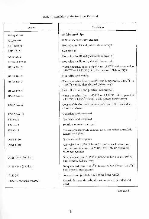
Table 4. Condition of the Steels, As Received
Alloy
Wrought iron
Armco iron
AISIC1010
AISI 1015
ASTM A36
ASTM A387-D
HSLA No. 1
HSLA No. 2
HSLA No. 3
HSLA No. 4
HSLA No. 5
HSLA No. 6
HSLA No. 12
HS No. 1
HS No. 2
HS No. 3
AISI 4130
AISI 4140
AISI 4340 (200 ksi)
AISI 4340 (150 ksi)
AISI 502
18% Ni, maraging (0.202)
Condition
As fabricated pipe
Mill finish, anodically cleaned
Hot rolled (mill) and pickled (laboratory)
Grit blasted
Hot rolled (mill) and pickled (laboratory)
Hot rolled (mill) and pickled (laboratory)
Water quenched from 1,650°F to 1,750°F and tempered at
1,100°F to 1,275°F (mill), blast cleaned (laboratory)
Hot rolled and pickled
Water quenched from 1,650°F and tempered at 1,150°F to
1,200°F (mill), blast cleaned (laboratory)
Hot rolled (mill) and pickled (laboratory)
Water quenched from 1,650°F to 1,750°F and tempered at
1,150°F to 1,275°F (mill), blast cleaned (laboratory)
Consumable electrode vacuum melt, hot rolled, annealed,
cleaned and oiled
Quenched and tempered
Quenched and tempered
Solution annealed and aged
Consumable electrode vacuum melt, hot rolled, annealed,
cleaned and oiled
Quenched and tempered
Austenized at 1,550°F for 0.7 hr, oil quenched to room
temperature, tempered at 900°F for 1 hr, air cooled to
room temperature
Oil quenched from 1,5 50°F, tempered for 1 hr at 7-50°F,
blast cleaned (laboratory)
Oil quenched from 1,550°F, tempered for 1 hr at l,050oF,
blast cleaned (laboratory)
Annealed and pickled, No. 1 sheet finish (mill)
Electric furnace air melt, air cast, annealed, desealed and
oiled
Continued
21
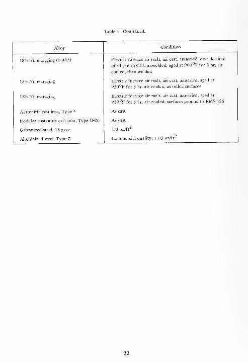
Table 4. Continued.
Alloy
18% Mi, maraging (0.082)
18% Ni, maraging
18% Ni, maraging
Austenitic cast iron, Type 4
Nodular austenitic cast iron, Type D-2c
Galvanized steel, 18 gage
Aluminized steel, Type 2
Condition
Electric furnace air melt, air cast, annealed, desealed and
oiled (mill); CEL unwelded, aged at 900°F for 3 hr, air
cooled, then welded
Electric furnace air melt, air cast, annealed, aged at
950°F for 3 hr, air cooled, as rolled surfaces
Electric furnace air melt, air cast, annealed, aged at
950°F for 3 hr, air cooled, surfaces ground to RMS-125
As cast
As cast
1.0 oz/ft2
Commercial quality, 1.03 oz/ft
22
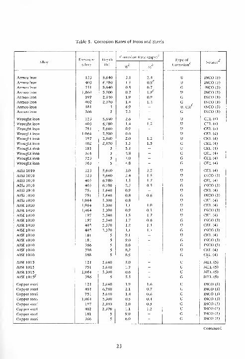
Table 5. Corrosion Rates of Irons and Steels
AlloyExposure
(day)
Depth
(ft)
Corrosion -late (mpv)'Type of
CorrosionSource
\Vb m"
Armco iron 123 5,640 3.1 2.4 U INCO (3)
Armco iron 403 6,780 1.5 0.5e U INCO(3)
Armco iron 751 5,640 0.8 0.7 G INCO (3)
Armco iron 1,064 5,300 0.7 1.9* U INCO (3)
Armco iron 197 2,340 1.9 0.9 G INCO (3)
Armco iron 402 2,370 1.4 1.4 Gu, cr/
INCO (3)
Armco iron 181 5 6.9 - INCO (3)
Armco iron 366 5 7.1 " G INCO (3)
Wrought iron 123 5,640 2.6 - U CEL (4)
Wrought iron 403 6,780 1.4 1.2 u CEL (4)
Wrought iron 751 5,640 0.9 - u CEL (4)
Wrought iron 1,064 5,300 0.6 - u CEL (4)
Wrought iron 197 2,340 2.0 1.2 u CEL (4)
Wrought iron 402 2,370 1.5 1.5 G CEL (4)
Wrought iron 181 5 5.3 - U CEL (4)
Wrought iron 364 5 4.8 - G CEL (4)
Wrought iron 723 5 4.0 - G CEL (4)
Wrought iron 763 5 4.8 - G CEL (4)
AISI 1010 123 5,640 3.0 2.2 U CEL (4)
AISI 1010 123 5,640 2.4 1.5 U INCO (3)
AISI 1010 403 6,780 1.5 1.7 u CEL (4)
AISI 1010 403 6,780 2.3 0.5 G INCO (3)
AISI 1010 751 5,640 0.9 - u CEL (4)
AISI 1010 751 5,640 0.8 0.6 G INCO (3)
AISI 1010 1,064 5,300 0.8 - U CEL (4)
AISI 1010 1,064 5,300 1.1 1.0 u CEL (4)
AISI 1010 1,064 5,300 0.9 0.5 u INCO (3)
AISI 1010 197 2,340 1.5 1.7 u CEL (4)
AISI 1010 197 2,340 1.7 0.6 G INCO (3)
AISI 1010 402 2,370 1.2 1.1 u CEL (4)
AISI 1010 402 2,370 1.1 1.1 G INCO (3)
AISI 1010 181 5 9.1 - U CEL (4)
AISI 1010 181 5 9.0 - G INCO (3)
AISI 1010 366 5 8.0 - G INCO (3)
AISI 1010 398 5 8.2 - U CEL (4)
AISI 1010 588 5 8.9 - G CEL (4)
AISI 1015 123 5,640 3.0 - U MEL (5)
AISI 1015 751 5,640 1.7 - u MEL (5)
AISI 1015 1,064 5,300 0.6 - u MEL (5)
AISI 1015s 386 5 5.3 - G MEL (5)
Copper steel 123 5,640 1.9 1.6 u INCO (3)
Copper steel 403 6,780 2.1 0.7 G INCO (3)
Copper steel 751 5,640 1.4 0.6 G INCO (3)
Copper steel 1,064 5,300 0.5 0.4 U INCO (3)
Copper steel 197 2,340 2.0 0.5 G INCO (3)
Copper steel 402 2,370 1.1 1.2 U INCO (3)
Copper steel 181 5 9.0 - G INCO (3)
Copper steel 366 5 6.0 - G INCO (3)
23

Table 5. Continued
AlloyExposure
(day)
Depth
(ft)
Corrosion Rate (mpy)Tvpe of
CorrosionSource
wb M6
ASTM A36 123 5,640 3.1 2.4 U CEL (4)
ASTM A36 403 6,780 1.5 1.8 U CEL (4)
ASTM A 36 751 5,640 0.9 - U CEL (4)
ASTM A 36 1,064 5,300 0.6 - U CEL (4)
ASTM A 36 197 2,340 1.7 1.7 U CEL (4)
ASTM A 36 402 2,370 1.3 1.5 U CEL (4)
ASTM A36 181 5 10.7 - G, C (8) CEL (4)
ASTM A36 398 5 6.2 - G CEL (4)
ASTM A36 540 5 6.3 - G CEL (4)
ASTM A36 588 5 5.8 " G CEL (4)
ASTM A387-D 123 5,640 3.0 2.3 U CEL (4)
ASTM A387-D 403 6,780 2.0 1.9 U CEL (4)
ASTM A387-D 751 5,640 0.9 0.9 U CEL (4)
ASTM A387-D 197 2,340 1.8 2.0 U CEL (4)
ASTM A387-D 402 2,370* 1.3 1.3 u CEL (4)
HSLA No. 1 123 5,640 2.9 2.2 u CEL (4)
HSLA No. 1 403 6,780 2.0 1.2 u CEL (4)
HSLA No. 1 751 5,640 0.9 - u CEL (4)
HSLA No. 1 1,064 5,300 0.6 - u CEL (4)
HSLA No. 1 1,064 5,300 0.6 0.7 u CEL (4)
HSLA No. 1 197 2,340 1.4 1.4 u CEL (4)
HSLA No. 1 402 2,370 1.0 1.0 u CEL (4)
HSLA No. 1 181 5 9.7 - G, P CEL (4)
HSLA No. 1 398 5 5.2 - G, P CEL (4)
HSLA No. 1 588 5 4.7 - G, P CEL (4)
HSLA No. 2 123 5,640 4.7 4.3 u CEL (4)
HSLA No. 2 403 6,780 2.1 2.2 u CEL (4)
HSLA No. 2 751 5,640 0.9 - u CEL (4)
HSLA No. 2 1,064 5,300 0.5 - u CEL (4)
HSLA No. 2 197 2,340 1.4 1.4 u CEL (4)
HSLA No. 2 197 2,340 1.1 - G Boeing (6)
HSLA No. 2 402 2,370 1.3 1.1 u CEL (4)
HSLA No. 2 181 5 6.8 - G, P CEL (4)
HSLA No. 2 398 5 4.5 - U, P CEL (4)
HSLA No. 2 540 5 4.4 - G, P CEL (4)
HSLA No. 3 1,064 5,300 0.7 - U CEL (4)
HSLA No. 4 123 5,640 3.6 - u CEL (4)
HSLA No. 4 123 5,640 4.3 1.8 U, C (9) INCO (3)
HSLA No. 4 403 6,780 3.3 2.3 U CEL (4)
HSLA No. 4 403 6,780 2.1 0.4 G INCO (3)
HSLA No. 4 751 5,640 1.2 - U CEL (4)
HSLA No. 4 751 5,640 0.9 0.7 G INCO (3)
HSLA No. 4 1,064 5,300 0.3 - U CEL (4)
HSLA No. 4 1,064 5,300 1.1 - U CEL (4)
HSLA No. 4 1,064 5,300 0.6 0.6 u INCO (3)
HSLA No. 4 197 2,340 1.4 0.9 u CEL (4)
HSLA No. 4 197 2,340 2.2 0.7 G INCO (3)
HSLA No. 4 402 2,370 1.1 1.1 G CEL (4)
Continued
24
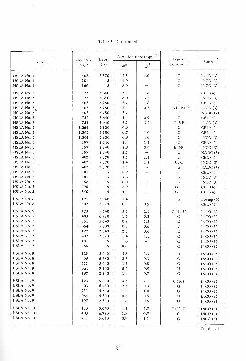
Table 5. Continued
AlloyExposure
(day)
Depth
(ft)
Corrosion Rate (mpy)'Tvpe of
CorrosionSource
Wfc Mb
HSLA No. 4 402 2,370 1.3 1.0 G INCO (3)
HSLA No. 4 181 5 11.0 - G INCO (3)
HSLA No. 4 366 5 8.0 - G INCO (3)
HSLA No. 5 123 5,640 3.1 1.6 U GEL (4)
HSLA No. 5 123 5,640 6.0 3.5 E INCO (3)
HSLA No. 5 403 6,780 2.7 1.8 U CEL (4)
HSLA No. 5
HSLA No. 5*403 6,780 7.4 0.2 S-E, P (3) INCO (3)
403 6,780 3.7 - G NADC (7)
HSLA No. 5 751 5,640 1.4 0.9 U CEL (4)
HSLA No. 5 751 5,640 3.1 3.2 G, S-E INCO (3)
HSLA No. 5 1,064 5,300 0.9 - U CEL (4)
HSLA No. 5 1,064 5,300 0.7 1.0 u CEL (4)
HSLA No. 5 1,064 5,300 0.9 1.0 u INCO (3)
HSLA No. 5 197 2,340 1.4 1.5 u CEL (4)
HSLA No. 5 197 2,340 3.3 0.9 E, I-P INCO (3)
HSLA No. 5 197 2,340 2.5 - U NADC (7)
HSLA No. 5 402 2,370 1.1 1.3 U CEL (4)
HSLA No. 5
HSLA No. 5h
402 2,370 1.4 1.3 U, G INCO (3)
402 2,370 1.1 - G NADC (7)
HSLA No. 5 181 5 8.9 - U CEL (4)
HSLA No. 5 181 5 11.0 - G INCO (3)
HSLA No. 5 366 5 8.0 - G INCO (3)
HSLA No. 5 398 5 6.0 - G,P CEL (4)
HSLA No. 5 540 5 5.4 - G,P CEL (4)
HSLA No. 6 197 2,340 1.4 - G Boeing (6)
HSLA No. 6 402 2,370 0.9 0.9 U CEL (4)
HSLA No. 7 123 5,640 3.5 2.1 C (4), U INCO (3)
HSLA No. 7 403 6,780 1.5 0.3 G INCO (3)
HSLA No. 7 751 5,640 0.8 1.3 G INCO (3)
HSLA No. 7 1,064 5,300 0.8 0.6 U INCO (3)
HSLA No. 7 197 2,340 2.3 0.6 G INCO (3)
HSLA No. 7 402 2,370 1.4 1.1 G INCO (3)
HSLA No. 7 181 5 11.0 - G INCO (3)
HSLA No. 7 366 5 8.0 - G INCO (3)
HSLA No. 8 123 5,640 3.8 2.3 U INCO (3)
HSLA No. 8 403 6,780 2.3 0.3 G INCO (3)
HSLA No. 8 751 5,640 1.2 0.8 G INCO (3)
HSLA No. 8 1,064 5,300 0.7 0.5 U INCO (3)
HSLA No. 8 197 2,340 1.9 0.7 G INCO (3)
HSLA No. 9 123 5,640 4.3 2.1 C(10) INCO (3)
HSLA No. 9 403 6,780 2.5 0.3 G INCO (3)
HSLA No. 9 751 5,640 1.4 1.0 G INCO (3)
HSLA No. 9 1,064 5,300 0.6 0.5 U INCO (3)
HSLA No. 9 197 2,340 1.6 0.6 G INCO (3)
HSLA No. 10 123 5,640 4.1 2.5 C(9), U INCO (3)
HSLA No. 10 403 6,780 1.8 0.5 G INCO (3)
HSLA No. 10 751 5,640 0.9 1.1 G INCO (3)
25
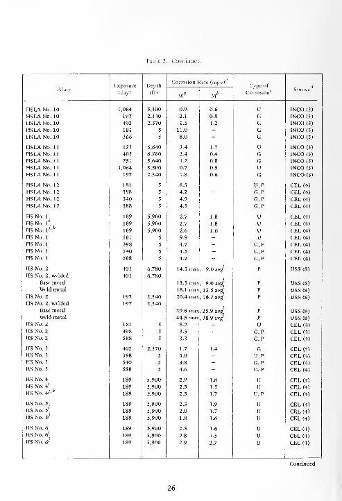
Table 5. Continued
Corrosion Kate (mpy)'
AlloyExposure
(day)
Depth
(ft)
Type of
CorrosionSource
w* Mb
HSLANo. 10 1,064 5,300 0.9 0.6 U INCO (3)
HSLA No. 10 197 2,340 2.1 0.8 G INCO(3)HSLANo. 10 402 2,370 1.5 1.2 G INCO (3)
HSLANo. 10 181 5 11.0 - G INCO (3)
HSLANo. 10 366 5 8.0 - G INCO (3)
HSLANo. 11 123 5,640 3.4 1.7 U INCO (3)
HSLANo. 11 403 6,780 2.4 0.4 G INCO (3)
HSLANo. 11 751 5,640 1.2 0.8 G INCO (3)
HSLANo. 11 1,064 5,300 0.7 0.5 U INCO (3)
HSLANo. 11 197 2,340 1.8 0.6 G INCO (3)
HSLANo. 12 181 5 8.5 - U, P CEL (4)
HSLANo. 12 398 5 4.2 - G,P CEL (4)
HSLANo. 12 540 5 4.9 - G, P CEL (4)
HSLANo. 12 588 5 4.3 - G, P CEL (4)
HS No. 1
.
189 5,900 2.7 1.8 U CEL (4)
HS No. l\
HS No. lh k
189 5,900 2.7 1.8 U CEL (4)
189 5,900 2.6 1.6 u CEL (4)
HS No. 1 181 5 9.9 - u CEL (4)
HS No. 1 398 5 4.7 - G,P CEL (4)
HS No. 1 540 5 4.5 - G, P CEL (4)
HS No. 1 588 5 4.2 - G, P CEL (4)
HS No. 2 403 6,780 14.5 max , 9.0 avg P USS (8)
HS No. 2, welded 403 6,780
Base metal 13.5 max , 9.0 avg P USS (8)
Weld metal 18.1 max ,13.5 avg P USS (8)
HS No. 2 197 2,340 20.4 max , 16.7 avg P USS (8)
HS No. 2, welded 197 2,340
Base metal 29.6 max , 25.9 avg' P USS (8)
Weld metal 44.5 max , 38.9 avg' P USS (8)
HS No. 2 181 5 8.2 - U CEL (4)
HS No. 2 398 5 3.5 - G, P CEL (4)
HS No. 2 588 5 3.3 - G, P CEL (4)
HS No. 3 402 2,370 1.7 1.4 G CEL (4)
HS No. 3 398 5 5.0 - U,P CEL (4)
HS No. 3 540 5 3.8 - G, P CEL (4)
HS No. 3 588 5 4.6 " G, P CEL (4)
HS No. 4 189 5,900 2.9 1.8 U CEL (4)
HS No. 4*.
HSNo. 47'*
189 5,900 2.3 1.5 u CEL (4)
189 5,900 2.5 1.7 U, P CEL (4)
HSNo. 5. 189 5,900 2.3 1.9 u CEL (4)
HS No. 5!
. 189 5,900 2.0 1.7 u CEL (4)
HS No. 57 189 5,900 1.8 1.6 u CEL (4)
HSNo. 6 189 5,900 2.5 1.6 u CEL (4)
HS No. 6\ 189 5,900 2.8 1.5 u CEL (4)
HS No. 6; 189 5,900 2.9 2.7 u CEL (4)
26

Table 5. Continued
AlloyExposure
(day)
Depth
(ft)
Corrosion Rate (mpy)'Type of
CorrosionSource
wfc M
12% Ni, maraging 197 2,340 2.4 - G Boeing (6)
18% Ni, maraging 123 5,640 3.6 - U NADC (7)
18% Ni, maraging 189 5,900 2.2 1.7 U CEL (4)
18% Ni, maraging 403 6,780 1.6 - u NADC (7)
18% Ni, maraging 197 2,340 1.6 - G Boeing (6)
18% Ni, maraging 197 2,340 2.9 - u NADC (7)
18% Ni, maraging 402 2,370 1.3 _ u NADC (7)
18% Ni, maraging 402 2,370 1.3 0.9 G CEL (4)
18% Ni, maraging 402 2,370 1.5 0.8 G INCO (3)
18% Ni, maraging (as rolled) 402 2,370 1.4 1.3 G CEL (4)
18% Ni, maraging (machined) 402 2,370 1.3 1.2 G CEL (4)
18% Ni, maraging 402 2,370 3.5 2.6 G CEL (4)
18% Ni, maraging' 402 2,370 2.8 1.7 G CEL (4)
18% Ni, maraging 181 5 5.4 - U, P CEL (4)
18% Ni, maraging 181 5 10.0 - P INCO (3)
18% Ni, maraging
18% Ni, maraging
181 5 5.8 - u CEL (4)
181 5 5.1 - u CEL (4)
18% Ni, maraging 366 5 7.0 - p INCO (3)
18% Ni, maraging 398 5 3.0 - U,P CEL (4)
18% Ni, maraging 588 5 3.1 - G, C, P CEL (4)
18% Ni, maraging 364 5 4.0 - G, P CEL (4)
18% Ni, maraging 723 5 3.5 - G,P CEL (4)
18% Ni, maraging
18% Ni, maraging
18% Ni, maraging
18% Ni, maraging
763 5 4.1 - G CEL (4)
364 5 4.0 - P, WB(G) CEL (4)
723 5 3.3 - G, P CEL (4)
763 5 3.9 - G CEL (4)
1.5% Ni steel 123 5,640 3.5 2.7 U INCO (3)
1.5% Ni steel 403 6,780 1.7 0.8 G INCO (3)
1.5% Ni steel 751 5,640 1.0 0.5 G INCO (3)
1.5% Ni steel 1,064 5,300 0.7 0.7 U INCO (3)
1.5% Ni steel 197 2,340 1.9 0.5 U INCO (3)
1.5% Ni steel 402 2,370 1.5 1.2 U INCO (3)
1.5% Ni steel 181 5 11.0 - G INCO (3)
1.5% Ni steel 366 5 8.0 - G INCO (3)
3% Ni steel 123 5,640 3.4 3.0 U INCO (3)
3% Ni steel 403 6,780 1.9 0.4 C (2), G INCO (3)
3% Ni steel 751 5,640 0.9 0.9 G INCO (3)
3% Ni steel 1,064 5,300 0.9 0.6 U INCO (3)
3% Ni steel 197 2,340 1.7 0.4 G INCO (3)
3% Ni steel 402 2,370 1.3 1.0 G INCO (3)
3% Ni steel 181 5 11.0 - G INCO (3)
3% Ni steel 366 5 8.0 - G INCO (3)
5% Ni steel 123 5,640 2.8 2.8 U INCO (3)
5% Ni steel 403 6,780 2.8 0.4 C (6), G INCO (3)
5% Ni steel 751 5,640 1.1 0.8 G INCO (3)
5% Ni steel 1,064 5,300 0.7 0.5 U INCO (3)
5% Ni steel 197 2,340 1.7 0.4 G INCO (3)
5% Ni steel 402 2,370 1.3 1.1 U INCO (3)
27
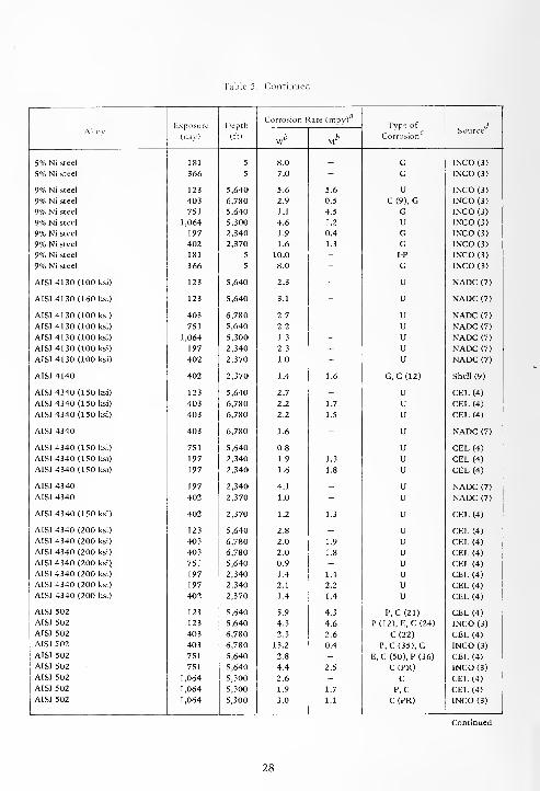
Table 5. Continued
AlloyExposure
(day)
Depth
(ft)
Corrosion Rate (mpy)Type of
Corrosion
dSource
wb M
5% Ni steel 181 5 8.0 _ G INCO (3)
5% Ni steel 366 5 7.0 - G INCO (3)
9% Ni steel 123 5,640 5.6 5.6 U INCO (3)
9% Ni steel 403 6,780 2.9 0.5 C (9), G INCO (3)
9% Ni steel 751 5,640 1.1 4.5 G INCO (3)
9% Ni steel 1,064 5,300 4.6 1.2 U INCO (3)
9% Ni steel 197 2,340 1.9 0.4 G INCO (3)
9% Ni steel 402 2,370 1.6 1.3 G INCO (3)
9% Ni steel 181 5 10.0 - I-P INCO (3)
9% Ni steel 366 5 8.0 " G INCO (3)
AISI 4130 (100 ksi) 123 5,640 2.3 - U NADC (7)
AISI 4130 (160 ksi) 123 5,640 3.1 - U NADC (7)
AISI 4130 (100 ksi) 403 6,780 2.7 - u NADC (7)
AISI 4130 (100 ksi) 751 5,640 2.2 - u NADC (7)
AISI 4130(100 ksi) 1,064 5,300 1.3 - u NADC (7)
AISI 4130 (100 ksi) 197 2,340 2.3 - u NADC (7)
AISI 4130 (100 ksi) 402 2,370 1.0 - u NADC (7)
AISI 4140 402 2,370 1.4 1.6 G,C (12) Shell (9)
AISI 4340 (ISO ksi) 123 5,640 2.7 - U CEL (4)
AISI 4340 (150 ksi) 403 6,780 2.2 1.7 U CEL (4)
AISI 4340 (150 ksi) 403 6,780 2.2 1.5 U CEL (4)
AISI 4340 403 6,780 1.6 - U NADC (7)
AISI 4340 (150 ksi) 751 5,640 0.8 - U CEL (4)
AISI 4340 (150 ksi) 197 2,340 1.9 1.3 U CEL (4)
AISI 4340 (150 ksi) 197 2,340 1.6 1.8 U CEL (4)
AISI 4340 197 2,340 4.1 - U NADC (7)
AISI 4340 402 2,370 1.0 - U NADC (7)
AISI 4340 (150 ksi) 402 2,370 1.2 1.3 U CEL (4)
AISI 4340 (200 ksi) 123 5,640 2.8 - U CEL (4)
AISI 4340 (200 ksi) 403 6,780 2.0 1.9 u CEL (4)
AISI 4340 (200 ksi) 403 6,780 2.0 1.8 u CEL (4)
AISI 4340 (200 ksi) 751 5,640 0.9 - u CEL (4)
AISI 4340 (200 ksi) 197 2,340 1.4 1.4 u CEL (4)
AISI 4340 (200 ksi) 197 2,340 2.1 2.2 u CEL (4)
AISI 4340 (200 ksi) 402 2,370 1.4 1.4 u CEL (4)
AISI 502 123 5,640 5.9 4.3 P,C (21) CEL (4)
AISI 502 123 5,640 4.3 4.6 P(12), E, C (24) INCO (3)
AISI 502 403 6,780 2.3 2.6 C(22) CEL (4)
AISI 502 403 6,780 13.2 0.4 P, C (35), G INCO (3)
AISI 502 751 5,640 2.8 - E,C (50), P(36) CEL (4)
AISI 502 751 5,640 4.4 2.5 C (PR) INCO (3)
AISI 502 1,064 5,300 2.6 - C CEL (4)
AISI 502 1,064 5,300 1.9 1.7 P, C CEL (4)
AISI 502 1,064 5,300 3.0 1.1 C(PR) INCO (3)
28
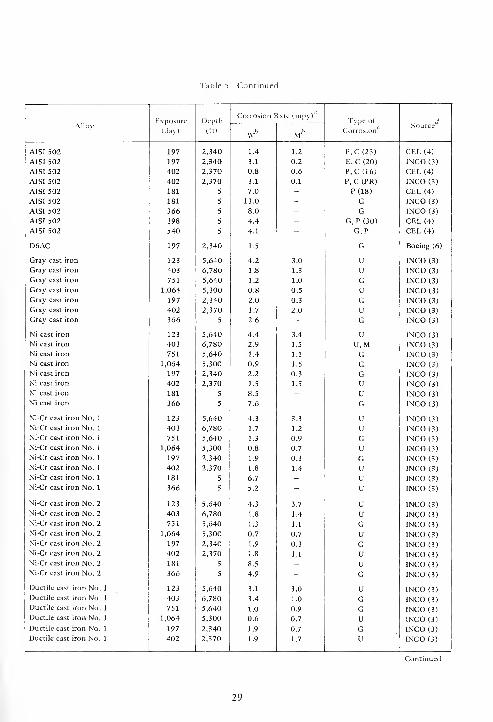
Table 5. Continuec
AlloyExposure
(day)
Depth
(ft)
Corrosion Rate (mpy)Type of
/" cCorrosion
Source
Wfe Mfc
AISI 502 197 2,340 1.4 1.2 P,C (23) CEL (4)
AISI 502 197 2,340 3.1 0.2 E, C (20) INCO (3)
AISI 502 402 2,370 0.8 0.6 P,C (16) CEL (4)
AISI 502 402 2,370 3.1 0.1 P, C (PR) INCO (3)
AISI 502 181 5 7.0 - P(18) CEL (4)
AISI 502 181 5 13.0 - G INCO (3)
AISI 502 366 5 8.0 - G INCO (3)
AISI 502 398 5 4.4 - G, P (30) CEL (4)
AISI 502 540 5 4.1 - G,P CEL (4)
D6AC 197 2,340 1.5 - G Boeing (6)
Gray cast iron 123 5,640 4.2 3.0 U INCO (3)
Gray cast iron 403 6,780 1.8 1.3 U INCO (3)
Gray cast iron 751 5,640 1.2 1.0 G INCO (3)
Gray cast iron 1,064 5,300 0.8 0.5 U INCO (3)
Gray cast iron 197 2,340 2.0 0.3 G INCO (3)
Gray cast iron 402 2,370 1.7 2.0 U INCO (3)
Gray cast iron 366 5 2.6 - G INCO (3)
Ni cast iron 123 5,640 4.4 3.4 U INCO (3)
Ni cast iron 403 6,780 2.9 1.5 U, M INCO (3)
Ni cast iron 751 5,640 1.4 1.1 G INCO (3)
Ni cast iron 1,064 5,300 0.9 1.5 G INCO (3)
Ni cast iron 197 2,340 2.2 0.3 G INCO (3)
Ni cast iron 402 2,370 1.5 1.5 U INCO (3)
Ni cast iron 181 5 8.5 - U INCO (3)
Ni cast iron 366 5 7.6 - G INCO (3)
Ni-Cr cast iron No. 1 123 5,640 4.3 3.3 U INCO (3)
Ni-Cr cast iron No. 1 403 6,780 1.7 1.2 u INCO (3)
Ni-Cr cast iron No. 1 751 5,640 1.3 0.9 G INCO (3)
Ni-Cr cast iron No. 1 1,064 5,300 0.8 0.7 U INCO (3)
Ni-Cr cast iron No. 1 197 2,340 1.9 0.3 G INCO (3)
Ni-Cr cast iron No. 1 402 2,370 1.8 1.4 U INCO (3)
Ni-Cr cast iron No. 1 181 5 6.7 - U INCO (3)
Ni-Cr cast iron No. 1 366 5 5.2 - U INCO (3)
Ni-Cr cast iron No. 2 123 5,640 4.3 3.7 u INCO (3)
Ni-Cr cast iron No. 2 403 6,780 1.8 1.4 u INCO (3)
Ni-Cr cast iron No. 2 751 5,640 1.3 1.1 G INCO (3)
Ni-Cr cast iron No. 2 1,064 5,300 0.7 0.7 u INCO (3)
Ni-Cr cast iron No. 2 197 2,340 1.9 0.3 G INCO (3)
Ni-Cr cast iron No. 2 402 2,370 1.8 1.1 U INCO (3)
Ni-Cr cast iron No. 2 181 5 8.5 - U INCO (3)
Ni-Cr cast iron No. 2 366 5 4.9 - G INCO (3)
Ductile cast iron No. 1 123 5,640 3.1 3.0 U INCO (3)
Ductile cast iron No. 1 403 6,780 3.4 1.0 G INCO (3)
Ductile cast iron No. 1 751 5,640 1.0 0.9 G INCO (3)
Ductile cast iron No. 1 1,064 5,300 0.6 0.7 U INCO (3)
Ductile cast iron No. 1 197 2,340 1.9 0.7 G INCO (3)
Ductile cast iron No. 1 402 2,370 1.9 1.7 U INCO (3)
29
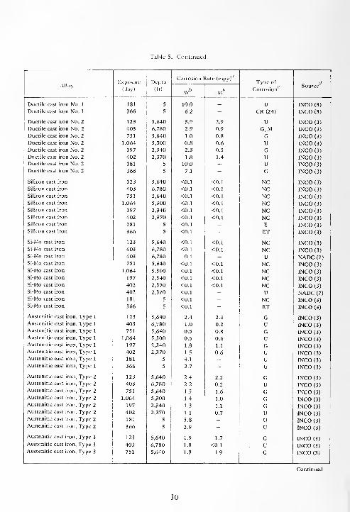
Table 5. Continued
Corrosion Rate (mpv)
AlloyExposure Depth Type of
c dSource
(day) (ft)\v
b Mb Corrosion""
Ductile cast iron No. 1 181 5 10.0 - U INCO (3)
Ductile cast iron No. 1 366 5 6.2 - CR (24) INCO (3)
Ductile cast iron No. 2 123 5,640 3.9 2.9 U INCO (3)
Ductile cast iron No. 2 403 6,780 2.9 0.9 G,M INCO (3)
Ductile cast iron No. 2 751 5,640 1.0 0.8 G INCO (3)
Ductile cast iron No. 2 1,064 5,300 0.8 0.6 U INCO (3)
Ductile cast iron No. 2 197 2,340 2.3 0.5 G INCO (3)
Ductile cast iron No. 2 402 2,370 1.8 1.4 U INCO (3)
Ductile cast iron No. 2 181 5 10.0 - u INCO (3)
Ductile cast iron No. 2 366 5 7.1 - G INCO (3)
Silicon cast iron 123 5,640 <0.1 <0.1 NC INCO (3)
Silicon cast iron 403 6,780 <0.1 <0.1 NC INCO (3)
Silicon cast iron 751 5,640 <0.1 <0.1 NC INCO (3)
Silicon cast iron 1,064 5,300 <0.1 <0.1 NC INCO (3)
Silicon cast iron 197 2,340 <0.1 <0.1 NC INCO (3)
Silicon cast iron 402 2,370 <0.1 <0.1 NC INCO (3)
Silicon cast iron 181 5 <0.1 - E INCO (3)
Silicon cast iron 366 5 <0.1 - ET INCO (3)
Si-Mo cast iron 123 5,640 <0.1 <0.1 NC INCO (3)
Si-Mo cast iron 403 6,780 <0.1 <0.1 NC INCO (3)
Si-Mo cast iron 403 6,780 0.1 - U NADC (7)
Si-Mo cast iron 751 5,640 <0.1 <0.1 NC INCO (3)
Si-Mo cast iron 1,064 5,300 <0.1 <0.1 NC INCO (3)
Si-Mo cast iron 197 2,340 <0.1 <0.1 NC INCO (3)
Si-Mo cast iron 402 2,370 <0.1 <0.1 NC INCO (3)
Si-Mo cast iron 402 2,370 <0.1 - U NADC (7)
Si-Mo cast iron 181 5 <0.1 - NC INCO (3)
Si-Mo cast iron 366 5 <0.1 - ET INCO (3)
Austenitic cast iron, Type 1 123 5,640 2.4 2.4 G INCO (3)
Austenitic cast iron, Type 1 403 6,780 1.0 0.2 U INCO (3)Austenitic cast iron, Type 1 751 5,640 0.5 0.8 G INCO (3)
Austenitic cast iron, Type 1 1,064 5,300 0.5 0.6 U INCO (3)Austenitic cast iron, Type 1 197 2,340 1.8 1.1 G INCO (3)Austenitic cast iron, Type 1 402 2,370 1.5 0.6 U INCO (3)Austenitic cast iron, Type 1 181 5 4.1 - U INCO (3)
Austenitic cast iron, Type 1 366 5 2.7 - u INCO (3)
Austenitic cast iron, Type 2 123 5,640 2.4 2.2 G INCO (3)Austenitic cast iron, Type 2 403 6,780 2.2 0.2 u INCO (3)Austenitic cast iron, Type 2 751 5,640 1.5 1.6 G INCO (3)Austenitic cast iron, Type 2 1,064 5,300 1.4 1.0 G INCO (3)Austenitic cast iron, Type 2 197 2,340 1.3 1.1 G INCO (3)Austenitic cast iron, Type 2 402 2,370 1.1 0.7 U INCO (3)Austenitic cast iron, Type 2 181 5 5.8 - u INCO (3)Austenitic cast iron, Type 2 366 5 2.9 - u INCO (3)
Austenitic cast iron, Type 3 123 5,640 1.9 1.7 G INCO (3)
Austenitic cast iron, Type 3 403 6,780 1.8 <0.1 u INCO (3)
Austenitic cast iron, Type 3 751 5,640 1.9 1.9 G INCO (3)
30

Table 5. Continued
AlloyExposure
(day)
Depth
(ft)
Corrosion Rate (mpv)1
Tvpe of
CorrosionSource
Wb Mb
Austenitic cast iron, Type 3 1,064 5,300 1.2 0.8 U INCO (3)
Austenitic cast iron, Type 3 197 2,340 0.8 0.7 G INCO (3)
Austenitic cast iron, Type 3 402 2,370 0.6 0.7 U INCO (3)
Austenitic cast iron, Type 3 181 5 5.0 - U INCO (3)
Austenitic cast iron, Type 3 366 5 2.8 - u INCO (3)
Austenitic cast iron, Type 4 123 5,640 1.8 1.6 G INCO (3)
Austenitic cast iron, Type 4 189 5,900 2.0 1.4 u CEL (4)
Austenitic cast iron, Type 4 403 6,780 2.0 1.3 u INCO (3)
Austenitic cast iron, Type 4 751 5,640 1.2 1.5 G INCO (3)
Austenitic cast iron, Type 4 1,064 5,300 0.9 0.4 u INCO (3)
Austenitic cast iron, Type 4 197 2,340 0.8 0.4 G INCO (3)
Austenitic cast iron, Type 4 402 2,370 0.9 0.7 G CEL (4)
Austenitic cast iron, Type 4 402 2,370 0.8 0.3 U INCO (3)
Austenitic cast iron, Type 4 181 5 3.8 - u CEL (4)
Austenitic cast iron, Type 4 181 5 3.4 - u INCO (3)
Austenitic cast iron. Type 4 364 5 2.4 - G CEL (4)
Austenitic cast iron, Type 4 366 5 2.4 - u INCO (3)
Austenitic cast iron. Type 4 723 5 2.0 - G CEL (4)
Austenitic cast iron, Type 4 763 5 2.0 - G CEL (4)
Austenitic cast iron, D-2 123 5,640 2.6 2.4 G INCO (3)
Austenitic cast iron, D-2 403 6,780 1.2 0.2 U INCO (3)
Austenitic cast iron, D-2 751 5,640 1.3 1.5 G INCO (3)
Austenitic cast iron, D-2 1,064 5,300 1.1 0.4 U INCO (3)
Austenitic cast iron, D-2 197 2,340 1.2 0.2 G INCO (3)
Austenitic cast iron, D-2 402 2,370 1.1 0.5 U INCO (3)
Austenitic cast iron, D-2 181 5 4.3-' G INCO (3)
Austenitic cast iron, D-2 366 5 2.4 - G INCO (3)
Austenitic cast iron, D-2b 123 5,640 2.1 2.0 G INCO (3)
Austenitic cast iron, D-2b 403 6,780 1.6 0.1 U INCO (3)
Austenitic cast iron, D-2b 751 5,640 1.2 1.3 G INCO (3)
Austenitic cast iron, D-2b 1,064 5,300 1.0 0.4 G INCO (3)
Austenitic cast iron, D-2b 197 2,340 1.4 0.1 G INCO (3)
Austenitic cast iron, D-2b 402 2,370 0.9 0.6 U INCO (3)
Austenitic cast iron, D-2b 181 5 4.1 - G INCO (3)
Austenitic cast iron, D-2b 366 5 2.7 -• G INCO (3)
Austenitic cast iron, D-2c 189 5,900 3.3 1.5 U CEL (4)
Austenitic cast iron, D-2c 402 2,370 1.8 1.2 U CEL (4)
Austenitic cast iron, D-2c 181 5 3.9 - u CEL (4)
Austenitic cast iron, D-2c 364 5 3.2 - G CEL (4)
Austenitic cast iron, D-2c 723 5 3.1 - u CEL (4)
Austenitic cast iron, D-2c 763 5 2.8 - u CEL (4)
Austenitic cast iron, D-3 123 5,640 1.9 2.2 G INCO (3)
Austenitic cast iron, D-3 402 6,780 2.7 0.4 G INCO (3)
Austenitic cast iron, D-3 751 5,640 2.1 1.9 G INCO (3)
Austenitic cast iron, D-3 1,064 5,300 1.2 0.7 U INCO (3)
Austenitic cast iron, D-3 197 2,340 0.9 0.2 G INCO (3)
Austenitic cast iron, D-3 402 2,370 0.7 0.5 U INCO (3)
Austenitic cast iron, D-3 181 5 4.3 - G INCO (3)
31
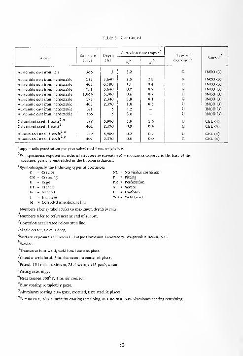
Table 5. Continued
AlloyExposure
(day)
Depth
(ft)
Corrosion Rate (mpy)'Type of
Corrosion
dSource
wb M fc
Austenitic cast iron, D-3 366 5 3.2 - G 1NCO (3)
Austenitic cast iron, hardenable 123 5,640 2.5 2.8 G INCO (3)
Austenitic cast iron, hardenable 403 6,780 1.1 0.4 U INCO(3)
Austenitic cast iron, hardenable 751 5,640 0.7 0.7 G INCO (3)
Austenitic cast iron, hardenable 1,064 5,300 0.6 0.7 U INCO (3)
Austenitic cast iron, hardenable 197 2,340 2.8 0.1 G INCO (3)
Austenitic cast iron, hardenable 402 2,370 1.8 0.5 U INCO (3)
Austenitic cast iron, hardenable 181 5 4.2 - U INCO (3)
Austenitic cast iron, hardenable 366 5 2.6 - u INCO (3)
Galvanized steel, 1 oz/ft 189 5,900 1.9 1.6 u CEL (4)
Galvanized steel, 1 oz/ft 402 2,370 0.9 0.4 G CEL (4)
Aluminized steel, 1 oz/ft 189 5,900 0.2 0.2 u CEL (4)
Aluminized steel, 1 oz/ft " 402 2,370 0.0 0.0 G CEL (4)
mpy = mils penetration per year calculated from weight loss.
W = specimens exposed on sides of structure in seawater; M = specimens exposed in the base of the
structure, partially embedded in the bottom sediment.
Symbols signify the following types of corrosion:
C = Crevice NC = No visible corrosion
CR = Cratering P = Pitting
E = Edge PR = Perforation
ET = Etched S = Severe
G = General U = Uniform
I = Incipient WB = Weld bead
M = Corroded at sediment line
Numbers after symbols refer to maximum depth in mils.
Numbers refer to references at end of report.
Corrosion accelerated below mud line.
•'Single crater, 12 mils deep_
^Surface exposure at Francis L. LaQue Corrosion Laboratory, Wrightsville Beach, N.C.
fcWelded.
Transverse butt weld, weld bead same as plate.
•'Circular weld bead, 3-in. diameter, in center of plate.
kPitted, 154 mils maximum, 73.4 average (15 pits), water.
Pitting rate, mpy.
Heat treated 900 F, 3 hr, air cooled.
Zinc coating completely gone.
Aluminum coating 50% gone, mottled, bare steel in places.
"\V = no rust, 78% aluminum coating remaining; M = no rust, 60% aluminum coating remaining.
32
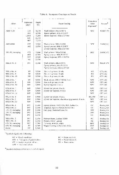
Table 6. Inorganic Coatings on Steels
AlloyExposure
(day)
Depth
(ft)Paint Coating
Condition
After
Exposure"
Source
AISI 4130 123 5,640 Wash primer, MIL-C-8541 NPF NADC (7)
403 6,780 Epoxy primer, MIL-P-23377
1,064 5,300 Epoxy topcoat, MIL-C-22750
197 2,340
402 2,370
AISI 4340 197 2,340 Wash primer, MIL-C-8541 NPF NADC (7)
402 2,370 Epoxy primer, MIL-P-23377
Epoxy topcoat, MIL-C-22750
18% Ni, maraging 123 5,640 Wash primer, MIL-C-8541 NPF NADC (7)
403 6,780 Epoxy primer, MIL-P-23377
197 2,340 Epoxy topcoat, MIL-C-22750
402 2,370
HSLA No. 5 197 2,340 Wash primer, MIL-C-8541
Epoxy primer, MIL-P-23377
Epoxy topcoat, MIL-C-22750
NPF NADC (7)
HSLA No. 4 189 5,900 Zinc rich primer, 8 mils RS CEL (4)
HSLA No. 5 189 5,900 Zinc rich primer, 8 mils RS CEL (4)
HSLA No. 13 189 5,900 Zinc rich primer, 8 mils RS CEL (4)
HSLA No. 4 189 5,900 Wash primer, MIL-C-8514, 1 mil NPF CEL (4)
HSLA No. 5 189 5,900 Zinc rich primer, 8 mils NPF CEL (4)
HSLA No. 13 189 5,900 Epoxy topcoat, 6 mils NPF CEL (4)
HSLA No. 4 189 5,900 Epoxy tar primer, 8 mils NPF CEL (4)
HSLA No. 5 189 5,900 Epoxy tar topcoat, 8 mils NPF CEL (4)
HSLA No. 1 3 189 5,900 NPF CEL (4)
HSLA No. 4 189 5,900 Epoxy tar primer, 8 mils RS, IPF CEL (4)
HSLA No. 5 189 5,900 Epoxy tar topcoat, aluminum pigmented, 8 mils NPF CEL (4)
HSLA No. 1 3 189 5,900 NPF CEL (4)
HSLA No. 3 197 2,340 Epoxy primer, 162-Y-26, W.P. Fuller Co. GC Boeing (6)
HSLA No. 6 197 2,340 Topcoat, Epicote Finish 26-64, Unit GC Boeing (6)
12% Ni, maraging 197 2,340 Gull gray, National Lead Co. FPF Boeing (6)
18% Ni, maraging 197 2,340 FPF Boeing (6)
D6AC 197 2,340 GC Boeing (6)
HSLA No. 3 197 2,340 Polyurethane, laminar X500 PC Boeing (6)
HSLA No. 6 197 2,340 Primer, 4-G-14, green PB Boeing (6)
12% Ni, maraging 197 2,340 Topcoat, 4-W-1A, white NPF Boeing (6)
18% Ni, maraging 197 2,340 Magna Coating and Chemical Co. FPF Boeing (6)
D6AC 197 2,340 GC Boeing (6)
Symbols signify the following:
GC = Good condition.
FPF = Few spots of paint failure.
IPF = Incipient paint failure.
NPF = No paint failure.
PC = Paint cracked.
PB = Paint blistered.
RS = Rust stains.
Numbers indicate references at end of report.
33
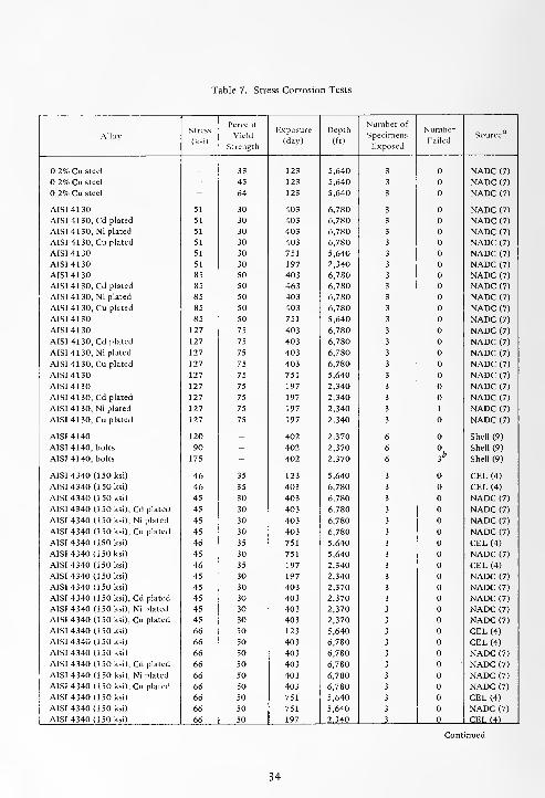
Table 7. Stress Corrosion Tests
AlloyStress
(ksi)
Percent
Yield
Strength
Exposure
(day)
Depth
(ft)
Number of
Specimens
Exposed
NumberFailed
Source
0.2% Cu steel _ 33 123 5,640 3 NADC (7)
0.2% Cu steel - 45 123 5,640 3 NADC (7)
0.2% Cu steel - 64 123 5,640 3 NADC (7)
AISI 4130 51 30 403 6,780 3 NADC (7)
AISI 41 30, Cd plated 51 30 403 6,780 3 NADC (7)
AISI 4130, Ni plated 51 30 403 6,780 3 NADC (7)
AISI 4130, Cu plated 51 30 403 6,780 3 NADC (7)
AISI 4130 51 30 751 5,640 3 NADC (7)
AISI 4130 51 30 197 2,340 3 NADC (7)
AISI 4130 85 50 403 6,780 3 NADC (7)
AISI 4130, Cd plated 85 50 463 6,780 3 NADC (7)
AISI 41 30, Ni plated 85 50 403 6,780 3 NADC (7)
AISI 4130, Cu plated 85 50 403 6,780 3 NADC (7)
AISI 41 30 85 50 751 5,640 3 NADC (7)
AISI 4130 127 75 403 6,780 3 NADC (7)
AISI 4130, Cd plated 127 75 403 6,780 3 NADC (7)
AISI 4130, Ni plated 127 75 403 6,780 3 NADC (7)
AISI 4130, Cu plated 127 75 403 6,780 3 NADC (7)
AISI 4130 127 75 751 5,640 3 NADC (7)
AISI 4130 127 75 197 2,340 3 NADC (7)
AISI 4130, Cd plated 127 75 197 2,340 3 NADC (7)
AISI 4130, Ni plated 127 75 197 2,340 3 1 NADC (7)
AISI 4130, Cu plated 127 75 197 2,340 3 NADC (7)
AISI 4140 120 - 402 2,370 6 Shell (9)
AISI 4140, bolts 90 - 402 2,370 6
3b
Shell (9)
AISI 4140, bolts 175 - 402 2,370 6 Shell (9)
AISI 4340 (150 ksi) 46 35 123 5,640 3 CEL (4)
AISI 4340 (150 ksi) 46 35 403 6,780 3 CEL (4)
AISI 4340 (150 ksi) 45 30 403 6,780 3 NADC (7)
AISI 4340 (150 ksi), Cd plated 45 30 403 6,780 3 NADC (7)
AISI 4340 (150 ksi), Ni plated 45 30 403 6,780 3 NADC (7)
AISI 4340 (150 ksi), Cu plated 45 30 403 6,780 3 NADC (7)
AISI 4340 (150 ksi) 46 35 751 5,640 3 CEL (4)
AISI 4340 (150 ksi) 45 30 751 5,640 3 NADC (7)
AISI 4340 (150 ksi) 46 35 197 2,340 3 CEL (4)
AISI 4340 (150 ksi) 45 30 197 2,340 3 NADC (7)
AISI 4340 (150 ksi) 45 30 403 2,370 3 NADC (7)
AISI 4340 (150 ksi), Cd plated 45 30 403 2,370 3 NADC (7)
AISI 4340 (150 ksi), Ni plated 45 30 403 2,370 3 NADC (7)
AISI 4340 (150 ksi), Cu plated 45 30 403 2,370 3 NADC (7)
AISI 4340 (150 ksi) 66 50 123 5,640 3 CEL (4)
AISI 4340 (150 ksi) 66 50 403 6,780 3 CEL (4)
AISI 4340 (150 ksi) 66 50 403 6,780 3 NADC (7)
AISI 4340 (150 ksi), Cd plated 66 50 403 6,780 3 NADC (7)
AISI 4340 (150 ksi), Ni plated 66 50 403 6,780 3 NADC (7)
AISI 4340 (150 ksi), Cu plated 66 50 403 6,780 3 NADC (7)
AISI 4340 (150 ksi) 66 50 751 5,640 3 CEL (4)
AISI 4340 (150 ksi) 66 50 751 5,640 3 NADC (7)
AISI 4340 (150 ksi) 66 50 197 2,340 3 CEL (4)
34

Table 7. Continued.
AlloyStress
(ksi)
Percent
Yield
Strength
Exposure
(day)
Depth
(ft)
Number of
Specimens
Exposed
NumberFailed
Source
AISI 4340 (150 ksi) 66 50 402 2,370 3 CEL (4)
AISI 4340 (150 ksi) 66 50 402 2,370 3 NADC (7)
AISI 4340 (150 ksi), Cd plated 66 50 402 2,370 3 NADC (7)
AISI 4340 (150 ksi), Ni plated 66 50 402 2,370 3 NADC (7)
AISI 4340 (150 ksi), Cu plated 66 50 402 2,370 3 NADC (7)
AISI 4340 (150 ksi) 99 75 123 5,640 3 CEL (4)
AISI 4340 (150 ksi) 99 75 403 6,780 3 CEL (4)
AISI 4340 (150 ksi) 99 75 403 6,780 3 NADC (7)
AISI 4340 (150 ksi), Cd plated 99 75 403 6,780 3 NADC (7)
AISI 4340 (150 ksi), Ni plated 99 75 403 6,780 3 NADC (7)
AISI 4340 (150 ksi), Cu plated 99 75 403 6,780 3 NADC (7)
AISI 4340 (150 ksi) 99 75 751 5,640 3 CEL (4)
AISI 4340 (150 ksi) 99 75 751 5,640 3 NADC (7)
AISI 4340 (150 ksi) 99 75 197 2,340 3 CEL (4)
AISI 4340 (150 ksi) 99 75 197 2,340 3 NADC (7)
AISI 4340 (150 ksi), Cd plated 99 75 197 2,340 3 NADC (7)
AISI 4340 (150 ksi), Ni plated 99 75 197 2,340 3 NADC (7)
AISI 4340 (150 ksi), Cu plated 99 75 197 2,340 3 NADC (7)
AISI 4340 (150 ksi) 99 75 402 2,370 3 CEL (4)
AISI 4340 (150 ksi) 99 75 402 2,370 3 NADC (7)
AISI 4340 (150 ksi), Cd plated 99 75 402 2,370 3 NADC (7)
AISI 4340 (150 ksi), Ni plated 99 75 402 2,370 3 NADC (7)
AISI 4340 (150 ksi), Cu plated 99 75 402 2,370 3 NADC (7)
AISI 4340 (200 ksi) 65 35 123 5,640 3 CEL (4)
AISI 4340 (200 ksi) 65 35 403 6,780 2 CEL (4)
AISI 4340 (200 ksi) 65 35 751 5,640 3 CEL (4)
AISI 4340 (200 ksi) 65 35 197 2,340 3 CEL (4)
AISI 4340 (200 ksi) 93 50 123 5,640 3 CEL (4)
AISI 4340 (200 ksi) 93 50 403 6,780 2 CEL (4)
AISI 4340 (200 ksi) 93 50 751 5,640 3 CEL (4)
AISI 4340 (200 ksi) 93 50 197 2,340 3 CEL (4)
AISI 4340 (200 ksi) 93 50 402 2,370 3 CEL (4)
AISI 4340 (200 ksi) 139 75 123 5,640 3 CEL (4)
AISI 4340 (200 ksi) 139 75 403 6,780 2 CEL (4)
AISI 4340 (200 ksi) 139 75 751 5,640 3 CEL (4)
AISI 4340 (200 ksi) 139 75 197 2,340 3 CEL (4)
AISI 4340 (200 ksi) 139 75 402 2,370 3 CEL (4)
ASTM A36 20 50 402 2,370 3 CEL (4)
ASTM A36 30 75 402 2,370 3 CEL (4)
ASTM A387-D 24 50 402 2,370 3 CEL (4)
ASTM A387-D 37 75 402 2,370 3 CEL (4)
HSLA No. lc
38 35 197 2,340 3 CEL (4)
HSLA No. 1 55 50 197 2,340 3 CEL (4)
HSLA No. 1 55 50 402 2,370 3 CEL (4)
HSLA No. 1 82 75 197 2,340 3 CEL (4)
HSLA No. 1 82 75 402 2,370 3 CEL (4)
HSLA No. 4d - 75 189 5,900 1 " CEL (4)
35

Table 7. Continued.
AlloyStress
(ksi)
Percent
Yield
Strength
Exposure
(day)
Depth
(ft)
Number of
Specimens
Exposed
NumberFailed
Source
HSLA No. 4e
75 189 5,900 2 CEL (4)
HSLA No. 4 - 75 189 5,900 1 CEL (4)
HSLA No. 5 41 35 197 2,340 3 CEL (4)
HSLA No. 5 59 50 197 2,340 3 CEL (4)
HSLA No. 5 59 50 402 2,370 3 CEL (4)
HSLA No. 5 89 75 197 2,340 3 CEL (4)
HSLA No. 5
HSLA No. 5d
89 75 402 2,370 3 CEL (4)
- 75 189 5,900 2 CEL (4)
HSLA No. 5e
HSLA No. /- 75 189 5,900 2 CEL (4)- 75 189 5,900 1 CEL (4)
HSLA No. 1 3d - 75 189 5,900 2 CEL (4)
HSLA No. 13e
HSLA No. 1/- 75 189 5,900 2 CEL (4)
- 75 189 5,900 1 CEL (4)
HS No. 3g 86 50 189 5,900 3 CEL (4)
HS No. 3h
86 50 189 5,900 3 CEL (4)
HS No. 3
HS No. 3h
129 75 189 5,900 3 CEL (4)
129 75 189 5,900 3 CEL (4)
HS No. 6
HS No. 6h
96 50 189 5,900 3 CEL (4)
96 50 189 5,900 3 CEL (4)
HS No. 6
HS No. 6b
143 75 189 5,900 3 CEL (4)
143 75 189 5,900 3 CEL (4)
HS No. 61
HS No. 6h '
'
96 50 189 5,900 3 CEL (4)
96 50 189 5,900 3 CEL (4)
HS No. 6* 143 75 189 5,900 3 CEL (4)
HS No. 6b '
'
143 75 189 5,900 3 CEL (4)
AISI 502 18 50 197 2,340 3 CEL (4)
AISI 502 18 50 402 2,370 3 CEL (4)
AISI 502 27 75 197 2,340 3 CEL (4)
AISI 502 27 75 402 2,370 3 CEL (4)
18% Ni, maraging 83 33 123 5,640 3 NADC (7)
18% Ni, maraging 105 42 123 5,640 3 NADC (7)
18% Ni, maraging
18% Ni, maraging'
158 50 189 5,900 3 CEL (4)
158 50 189 5,900 3 2 CEL (4)
18% Ni, maraging
18% Ni, maraging
237 75 189 5,900 3 3 CEL (4)
237 75 189 5,900 3 3 CEL (4)
18% Ni, maraging. - 75 403 6,780 3 3 NADC (7)
18% Ni, maraging'-' - 75 403 6,780 3 3 NADC (7)
18% Ni, maraging - 75 751 5,640 3 NADC (7)
18% Ni, maraging 70 35 197 2,340 3 Boeing (6)
18% Ni, maraging 100 50 197 2,340 3 Boeing (6)
18% Ni, maraging 150 75 197 2,340 3 Boeing (6)
18% Ni, maraging 75 30 197 2,340 3 NADC (7)
18% Ni, maraging 125 50 197 2,340 3 NADC (7)
18% Ni, maraging 188 75 197 2,340 3 NADC (7)
18% Ni, maraging. 75 30 197 2,340 3 NADC (7)
18% Ni, maraging. 125 50 197 2,340 3 NADC (7)
18% Ni, maraging''
188 75 197 2,340 3 3 NADC (7)
36
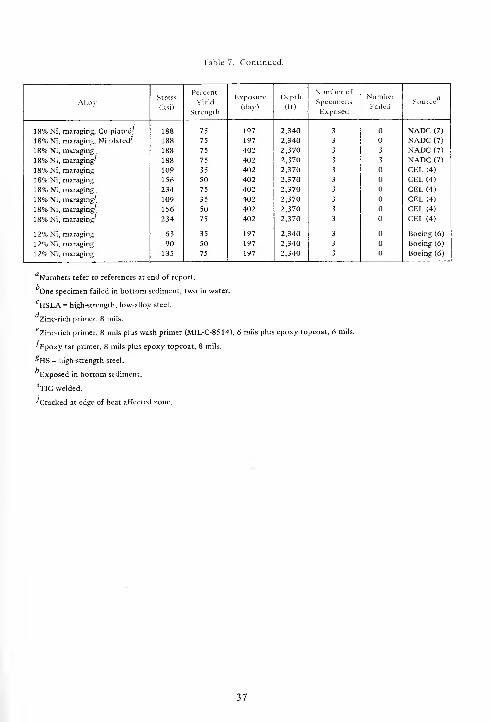
Table 7. Continued.
AlloyStress
(ksi)
Percent
Yield
Strength
Exposure
(day)
Depth
(ft)
Number of
Specimens
Exposed
NumberFailed
c aSource
18% Ni, maraging, Cu plated' 188 75 197 2,340 3 NADC (7)
18% Ni, maraging, Ni plated-' 188 75 197 2,340 3 NADC (7)
18% Ni, maraging. 188 75 402 2,370 3 3 NADC (7)
18% Ni, maraging-' 188 75 402 2,370 3 3 NADC (7)
18% Ni, maraging 109 35 402 2,370 3 CEL (4)
18% Ni, maraging 156 50 402 2,370 3 CEL (4)
18% Ni, maraging
.
234 75 402 2,370 3 CEL (4)
18% Ni, maraging^ 109 35 402 2,370 3 CEL (4)
18% Ni, maraging'. 156 50 402 2,370 3 CEL (4)
18% Ni, maraging^ 234 75 402 2,370 3 CEL (4)
12% Ni, maraging 63 35 197 2,340 3 Boeing (6)
12% Ni, maraging 90 50 197 2,340 3 Boeing (6)
12% Ni, maraging 135 75 197 2,340 3 Boeing (6)
"Numbers refer to references at end of report.
One specimen failed in bottom sediment, two in water.
CHSLA = high-strength, low-alloy steel.
Zinc-rich primer, 8 mils,
''zinc-rich primer, 8 mils plus wash primer (MIL-C-8514), 6 mils plus epoxy topcoat, 6 mils.
•^Epoxy tar primer, 8 mils plus epoxy topcoat, 8 mils.
^HS = high-strength steel.
Exposed in bottom sediment.
'TIG welded.
^Cracked at edge of heat affected zone.
37
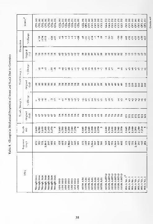
3O
* * * * * "* "* <**'>*'*-*'*•* * •* <* >* * * rr <J- * * * + * •+ Tf T)- T(- + ^" *J J J J J J J »J J _) J -J J J _j _j j j j _j _j J -1 J _ -; J _ -J J J J J Jw w w w w w w W Ct] W 03 03 W W H III U H U HI Id W 03 UJ u u w BJ w w w w w wu u u u u u u U U <J U (J u u u u u u u u u u CJ U u u U U U sj u U U (J
C X -ftr rn so fs h 00 m in •* m oo OS rt H i- H t OS SO (s. o O rsl is i-h N OS O f", ^H m rH , (S) tH + 1 1 1 1 1
H + <-h <-< <-h I 1 -H1
•* m m m rr, rr, w1 ,-. rt rt 1 + + 11+ 1 1 + + + + + + +
c (J + + +
coa C ^
"5j s°(si (si (s] (N (SI CM <s] Os ON OS ON OS Os ON (N <N) CS) r^ Csl rsl Csl fsl rsl rsl rsl
tf * <t -* *t * * m in m m w m m m m m m rn ro
6
cCM o m m X O « m » * + h (SI tJ- SO •+ * CS1 rH * SO ^ (N so ,H rn tJ- rr, rsl cH rH
-C1 + + 1 CJ 1 + + + + 1 1 + + + + + 1 1 + + + | 1 + + + + + + 1 +
S> Ucu!
oo
-a*u *«
> o o o o o o o so so SO so so so so ON ON Os Os Os Os ON Os Os OS Os OS 0s o o o o © o o-1- -t" * -t * -t
BO
in so so rsl rs iH h O so (N (N m H N rt * (M H H SO ts. * O (ft N (SI (SI rt H1 + + +
1 + + 1 + + + 1 + 1 + + + + + + + 1 + + + + + + + +
c u
00
I c r^ rs.tsrs.rsrsts.rs sr + + tt * * -* so so so so so so so SO sO SO SO so SO
o"""
sr * *( tt •+<) + SO SO so so so so so ts rs rs [s. f~ ts (S (SI rsl (SI rsl rsl (si
O O O O O O m O O O O O O m O © O O O O in O C O o o © O O O O O © in
a- £ * 00 "J" o + r-~ + 00 * O + s *t- 00 Tj- O Tt- (•* * X -+ O •+ rs *t x ^J- o st r^so t-s so rr, m m so ts so m m ro SO N SO (ft (ft (ft SO ts sO so rs so (ft rft rn
m \o m in (si (si in so in in (si rsi in so in m cs\ rsl m SO m in rsl rsl in so in in (si" (si
3 *-• rn rn rt * ts (SI rn (ft rft tH ^- rs fs) rH ro rfti ,-h -^- [v. (si ^h + t- Csl rn m rt * ts rsl -(/> >, rsl O u-t sO ON O X Cs] O m SO ON O 00 (S p m so Os O 00
i-i * rs ci
r* •* rtc SO OS o rsi o m so on O X
rt
3- T3w -* rs 0_ -i -* •-< rH * ts 0_ -1 Tt iH -t- rs O — -t *-> -t rs o_ -h * iH
^H r-7 ^H tH T-T
>>_o
< q c 9 9 9 9s c e c e b ats,
X i>-Ci
O o oO O O O O O O SO SO so so SO so so X X 00 X
O O O O oJ3 J3 -C -C J3 J3. J3 o o o o o o o <<<<<<< < < < < < < Z Z Z Z Z Z Zbo bo bo bo bo bo bo3 3 3 3 3 3 3O O O O O O O
S S S S S g s g g s g g g <<<<<<<00 00 on on on on on H r- H H H r- H f- H H H H H j j j j j j j
oo oo on on on oo oo on 00 00 00 00 00 on on oo on oo on onj5 & S S= £ £ & <<<<<<< <<<<<<< < < < < < < I X I I I X X
38
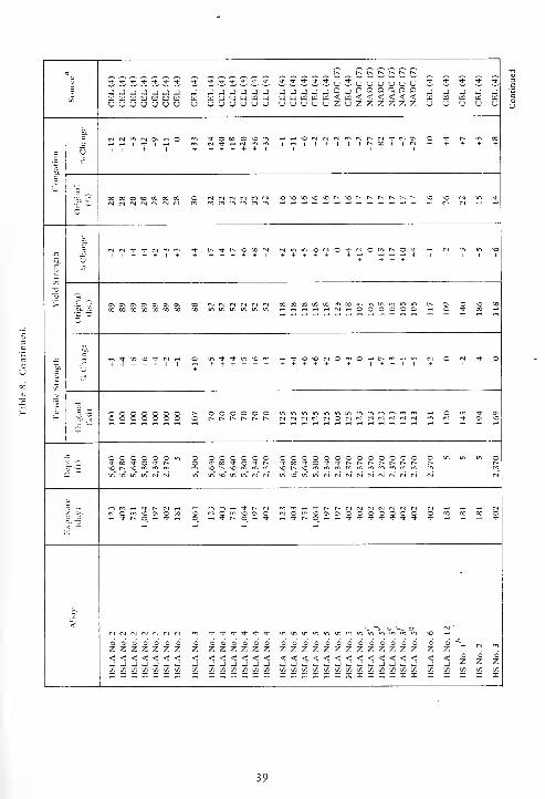
r^ t> t« r^ t-~ rs fs
u * -T Tt * Tt * Tt -t tT -T •* * Tt * Tt- * Tt * -r U Tt U 'J U U U u Tt Tt •* Tt st
D j J J _3 J J J J J J _ j J J J J J J J Q J D n Q D 2 Q<
J J J J Ja i u K a w III [I] ^ m w si w ui w ^ w a < u < < < < < cd w w w au u CJ U U u u sj <J u (J <j U u u u u u U Z o Z z Z Z z z U sj u u u
| Os o * o X c SO SO csl Csl r^ •+ Os o Tt c* 001* Tt 1 i t^ CO CM + + + +
c U 1 1 + 1 + + + + + + 1 1 1 1 1 i
bp
'^ 2 ___
*3i i-00 X CO CO CO CO 3 Csl rj Csl SO so SO so so f^ SO r-< t^ r^ t^ t-^ t^ SO SO Tt
CM CM CM
1CM Tt •* <si Tt r*. st c-s SO oc CSl so 3 -t csl o c^ o + so
1 + + + 1 + + + + + + + 1 + + + + + + ++
p
1
> "5.J2
Os OS Os Os Os o Os CO CM cm CSl CSl csl N 00 00 K 00 OC rn 00 m m m m m in t-^ OS o so COCO X CO CO CO 00 3 3 c 3 3 3 3 -r 00
Mr- z. ,_, * SO so -* Csl ,_, o in Tt * in SO en ,-t Tt SO so Csl O CO O r* r^ m ^i m CM O CM Tt 3
+ + + + + + + + + + + + + + + I + + 1 + 1
5£ U +U
X
5 .- •'r o C 3 3 c o o t^ O O 3 3 o C in in in in in m m m m CO m en rn ,H 3 m Tt OS
o~o o 3 3 o c 3 -
r> ts. r^ r-s rs. C-s c csl csl CM CM CM Tt OS SO
_ o C C 3 o o o c Q o o o O O o r O 3 O 3 O O 3 O O o 3<t X -t 3 -t r> 3 -+ CO Tt o Tt t^ Tt X Tt O Tt Tt t- t~. t^ f~ t~ t^ r> r^ C-*
so r^ SO so r^ so SO t^ •c
~ m SO in in <s CM m in SO m m Csl Csl in so m m CM Csl Csl Csl CM cs CM CM CM CM cm"
iTt- t~ cm * Tj" t^ Csl Tt t^ r-^ CS Csl <s) CM CM CM
CM o so Os 3 CO SO 3 c O O c Os OS 5 3 o c 3 c o 3 CO X 00 5Tt r^ 3 * O Tt r> c Tt Tt ^s o_ 4- Tt * Tt -1- st *
~
-
<rl CM CM CM (S CM (SI m Ti- •* * Tt Tt Tt in in m m m m in m ^m^m tn^ 60
SO 2'- o o O o o o O es O o O o O o o o o o o o o O O o •%Z Z Z Z Z z z z Z Z Z Z Z z Z 2 Z Z Z Z Z Z Z Z Z z Z Z Z .
< < < < < < < < < < < < < < < < < < < < < < < < < < < < < 6Z Z Zj J _) j _) -) J j -J -J -J j J _> J J ~i J -J j J j J j _ J J J
GO 00 X in Efl 00 00 X on 00 X 00 00 00 X 00 X X 00 00 X 00 00 X 00 00 X 00 00 00= - X - X I X I :: X X X X X X X - X - X X X - X X X X X X X X X
39
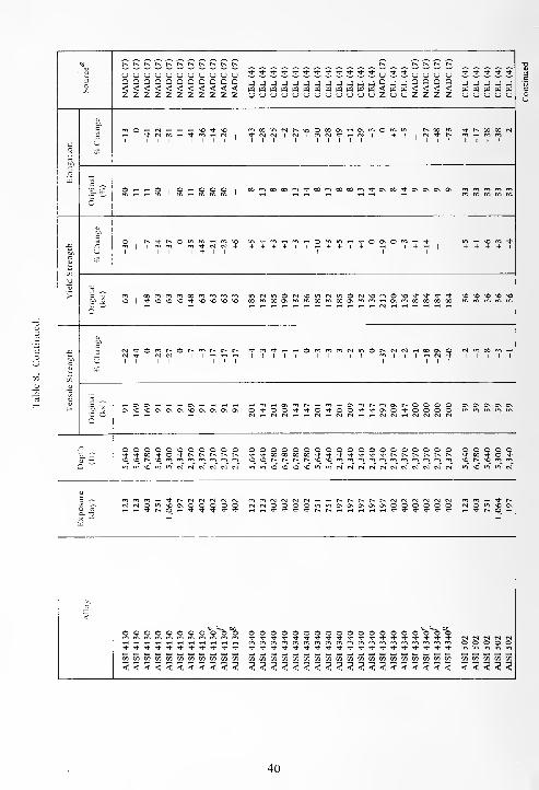
3oen
r-* t^ t^ r~ tssr^r^t^r^r~t^r^r^r^r~t^
uuuuuuououoQQQDQQQQQQQ<<<<<<<<<<<zzzzzzzzzzzSJJJJJSJSSJJuJJu u
uuuuuuuuuuuuZuuZZUQ<Z
uD<Z
_ _ - - _w w w w wu u u u u
o
_o
5
c
U
r«0>-ICs1l-l.-l.-lsO*SO
1 1 1 I 1 1 1 1 1 '
rAOOsnCsir^soOXOs'-'Os's-iOfU-i r-*
-sfrs]Cs!lrs)|r<-><N*i-r-irJI +1 ifS+ + + + + + + + + ' 1
oo-t
I
* t^ CO 00 Csl
1 1 1 1
6
O <-i <-i o|O-hOOO
i
Mm«D0'n^00mcO00m1'Ov00 ,t^5\ o> ON -----
c
\r.
>
C
uO t-^-sft^ommwrrisom
| im is-i m + N N t
1 II 1 + 1 1
+ + + +II-H + +I+ rt l+<i+ 1 1
1 1
^> rH o m ++ + + + 1
c .c:
.2P -x
C"
m oo"im<s-s.o rr>mmmNO 1 ^vO'OnO'+nOnOsOnO C0r'>00Osromc0m000s<^fs-HOs'Y>CC00 fX
•*00
so so so so so
c
00
rs-^- N(SJ +|^HW^H sTt-ms+^H^HO^^roCslmOl^CslCslT-loO+ + + +I + + +I+ 1*1 | | + tH
1 1
Os o M in M m h1 1 1 1 1
OssOsOOsOsOssoosOsOsOs OfOO'*^-O'*OO'l-'*-0sO*OONHNMrtHNHNNHHNNHNNooCsl
OOcsl
Os Os Os ON Os
(
^ 3ooooooooooososoc^sommrnfs'srorrjfs's
QOOOOOOOOOOQOOOOO\0N0r^r^r^t^\0N0"">mmrr,mmmmro
o o p o o o o+ » st O stO MO«i"vim>oinin«NNNNrj Iftl/IVO^O^^^mNNNNNNNNN N Csl irs so i/s in Csl
O Mo- -ax —
'
(S!so^noonOOqqq rrjmcslCslrs]csl~HrHf.rs.r^r^r^rslfMCs!rs]CslrslOOQQu-iinosOsOsOsOsOQOO O Cen m ih * t-»N O m SO Osrt s* O 0_ -H
<
oooooooo o o "& OOOOOOOOOOOOOOO 0*0 O*!)csl csl csl csl c*l
o o o o o
t/ll/ltfl(fl«tfiW(fl«W[/l cncnc/5cnc/ic/)t/5crjc/5c/5ty3c/5coc/)c/)c/5c/) (/] <s~. yi « « yi tn
<<<<<<<<<<< <<<<<<<<<<<<<<<<< < < < < <C < <
40

»3
3o
t^ r^ t^ r^
^"^" r_icjCJU*^* ,:^"'^"^" ^+ ^" *!" ^ "^ "^
J J QQQQjJJJ J J J J -J _
u <j zzzzuuuu uuuo u u
1
1 h N rj m i \o *-n v\ y~t + m m m m| +
I -— l lll+ l + ll+
!§£ ^ m m mmiriinrricot^c^ N N ^ to CO GO
in—
^x,
•t CI QO^J-ITi H N 00 OOt^vOOO O t^
1 1 1
"S. j£sC^O h h h io h \0 0\ O O <N CN O Xmm + + + h io ro m (N tN -* * * m
N « M ro w N N
1 -Hin COCO^-rr.sovOOt^ *+ w X CO m M1+ m + <s ^H 1 I++ IrHr^^H + |III +11
fi mm tt-t^Nhlo^ N M + + Tt- m
""
Om OOOOOOOO O in O in O O"I ^ "\ "\ "1 "1 "i "1 m. "!. "• mm(S io ia* M (N N N N N N rN~ m" N*
3 -T; (Nr- mTj-r^rgcNMN<N (M ^* <n *-i <n cmOC0 fNOCNOOOOO O CO O CO o oTt- —
i ^hO^-4--*-**-!- + -< ^j" ,-H * -*
1
AISI
502
AISI
502
18
Ni,
maraging
18
Ni,
maraging
18
Ni,
maraging
18
Ni,
maraging
18
Ni,
maraging.
18
Ni,
maraging'
18
Ni,
maraging
18
Ni,
maraging
Austenitic
cast
iron,
Type
4
Austenitic
cast
iron,
Type
4
Austenitic
cast
iron,
Type
D-2C
Austenitic
cast
iron,
Type
D-2C
2
Galvanized
steel,
1
oz/ft
2
Aluminized
steel,
1
oz/ft
'£ 1 § a | §
xi5u Lu'zx5S<
41
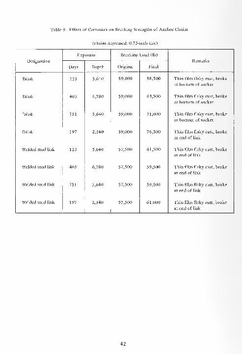
Table 9. Effect of Corrosion on Breaking Strengths of Anchor Chains
(chains degreased, 0.75-inch size)
Exposure Breaking Load (lb)
RemarksDesignation
Days Depth Original Final
Dilok 123 5,640 59,000 58,500 Thin film flaky rust, broke
at bottom of socket
Dilok 403 6,780 59,000 64,500 Thin film flaky rust, broke
at bottom of socket
Dilok 751 5,640 59,000 71,000 Thin film flaky rust, broke
at bottom of socket
Dilok 197 2,340 59,000 76,500 Thin film flaky rust, broke
at end of link
Welded stud link 123 5,640 57,500 61,500 Thin film flaky rust, broke
at end of link
Welded stud link 403 6,780 57,500 59,500 Thin film flaky rust, broke
at end of link
Welded stud link 751 5,640 57,500 59,500 Thin film flaky rust, broke
at end of link
Welded stud link 197 2,340 57,500 61,000 Thin film flaky rust, broke
at end of link
42
SECTION 3
COPPER ALLOYS
The excellent corrosion resistance of copper and
its alloys is partially due to its being a relatively noble
metal. However, in rr.anv environments, its satisfac-
tory performance depends on the formation of
adherent, relatively thin films of corrosion products.
In seawater corrosion, resistance depends on the
presence of a surface oxide film through which
oxygen must diffuse in order for corrosion to con-
tinue. This oxide film adjoining the metai is cuprous
oxide covered with a mixture of cupric oxy-chloride,
cupric hydroxide, basic cupric carbonate, and calcium
sulfate. Since oxvgen must diffuse through this film
for corrosion to occur, it would be expected that
under normal circumstances the corrosion rates
would decrease with increase in time of exposure.
Copper allovs corrode uniformly; hence, corrosion
rates calculated from weight losses and reported as
mils per year reflect the true condition of the alloys.
Therefore, corrosion rates for the copper alloys can
be used reliably for design purposes. However, this
does not apply to those copper base allovs which arc
susceptible to parting corrosion. (Parting corrosion is
defined as rne selective attack of one or more of the
components of a so! i solution allow) Examples of
parting corrosion arc dezincification, dealuminifica-
tion, denickelification, desiheonification, etc.
The data on the copper alloys were obtained from
the reports given in References 3 through 19 and 23.
The copper alloys are separated into the different
classes of copper alloys (coppers, brasses, bronzes,
and copper-nickel alloys) for comparison and dis-
cussion purposes.
The chemical compositions, corrosion rates and
types of corrosion, stress corrosion characteristics,
and changes in mechanical properties due to cor-
rosion of the coppers are given in Tables 10 through
13. The effects of duration of exposure are shown
graphically in Figures 8 and 15.
The chemical compositions, corrosion rates and
types of corrosion, stress corrosion characteristics,
and changes in mechanical properties due to the cor-
rosion of the brasses are given in Tables 14 through
17. The effects of the duration of exposure are shown
graphically in Figures 11 and 15.
i he chemical composr.ions, corrosion '-atec and
types of corrosion, stress corrosion characteristics,
and changes in mechanical properties due to
corrosion of the bronzes are given in Tables 18
through 21. The effects of the duration of exposure
are shown graphically in Figures 12 and 15.
The chemical compositions, corrosion rates and
types of corrosion, stress corrosion characteristics,
and changes in mechanical properties due to cor-
rosion of the copper-nickel alloys are given m Tables
22 through 25. The effects of the duration of
exposure are shown graphically in Figures 13 and 15.
The effects of depth and the effect of the concen-
tration of oxygen in seawater on the corrosion of the
copper alloys are shown in Figures 9 and 14.
The effect of the iron content on the corrosion of
the copper-nickel allovs is shown in Figure 14.
3.1. COPPERS
The chemical compositions of the coppers are
given : n Table 10. their corrosion rates and ^'pes of
corrosion in Table 11, their resistance to stress cor-
rosion cracking in Table 12, and the changes in their
mechanical properties due to corrosion in Table 13.
3.1.1. Duration of Exposure
The effects of the duration of exposure on the
corrosion of copper in seawater at depth, at the
surface, and in the bottom sediments are shown
graphically in Figure 8. At the surface and at the
6,000-foot depth, both in the seawater and in the
bottom sediment, the corrosion rates decreased with
increasing duration of exposure. At the 2,500-foot
depth the corrosion rates in the seawater and in the
bottom sediment were essentially constant. Also, the
corrosion rates were practically the same at depth as
at the surface.
The beryllium-copper alloys behaved very
similarly to copper, and their corrosion rates were
comparable. Beryllium-copper chain corroded at the
43

same rates and in the same manner as the alloy in
sheet form. Welding by either the TIG or MIG pro-
cesses as well as aging at either 600°F or 800°F did
not affect the corrosion behavior of the beryllium-
copper alloys.
3.1.2. Effect of Depth
The effect of depth on the corrosion of copper is
shown in Figure 9. The corrosion of copper was not
affected by depth, at least to a depth of 6,000 feet.
3.1.3. Effect of Concentration of Oxygen
The effect of the concentration of oxygen in sea-
water on the corrosion of copper is shown in Figure
10. The corrosion of copper was unaffected by the
concentration of oxygen in seawater within the range
of 0.4 to 5.75 ppm.
3.1.4. Stress Corrosion
Copper and beryllium-coppers were exposed in
the seawater while stressed at values equivalent to 30
and 75% of their respective yield strengths for the
periods of time and at the depths shown in Table 12.
Neither copper nor the beryllium-coppers were sus-
ceptible to stress corrosion. Aging at either 600°F or
800°F did not affect the stress corrosion resistance of
beryllium-copper (CDA No. 172).
3.1.5. Mechanical Properties
The effects of exposure in seawater on their
mechanical properties are given in Table 13. The
mechanical properties of the copper and the
beryllium-coppers were not significantly affected by
exposure in seawater at the surface or at depth.
3.1.6. Galvanic Corrosion
Dissimilar metal couples consisting of 1 x 2-inch
strips of aluminum alloy 7075-T6 fastened to
1 x 6-inch strips of beryllium-copper alloy (CDA No.
175) with plastic fasteners were exposed in seawater
at a depth of 2,500 feet for 402 days. After exposure
the 7075-T6 was covered with a heavy uniform layer
of corrosion products, while there was a thin layer of
corrosion products on the CDA No. 175 alloy. This
indicates that the aluminum was corroding galvani-
cally to protect the beryllium-copper from corroding.
3.2. BRASSES (Copper-Zinc Alloys)
The chemical compositions of the brasses are
given in Table 14, their corrosion rates and types of
corrosion in Table 15, their resistance to stress cor-
rosion cracking in Table 16, and the changes in their
mechanical properties due to corrosion in Table 17.
3.2.1. Duration of Exposure
The effects of the duration of exposure on the
corrosion of the brasses in seawater at depth, at the
surface, and in the bottom sediments are shown in
Figure 1 1.
Since the corrosion rates of all the brasses, except
those of alloys, CDA No. 280 and 675, were so com-
parable, the average values for any one time, depth,
or environment were used to prepare the curves in
Figure 11. The corrosion rate values of alloys CDANo. 280 (Muntz Metal) and CDA No. 675 (manganese
bronze A) were considerably higher than those of all
the other brasses. These high rates were attributed to
the severe parting corrosion (dezincification) which
had occurred on these two alloys.
The curves in Figure 1 1 show the effects of the
duration of exposure on the corrosion of the brasses
in seawater. The corrosion rates of the brasses
decreased slighdy with increasing duration of
exposure at the surface and at depths of 2,500 and
6,000 feet both in seawater and in the bottom
sediments. The corrosion of the brasses was the same
in the bottom sediments as in the seawater at the
6,000-foot depth, but slower in the bottom sediments
than in the seawater at the 2,500-foot depth. The
corrosion in seawater was practically the same at the
2,500-foot depth as at the 6,000-foot depth. The
brasses corroded slighdy slower at depth than at the
surface.
3.2.2. Parting Corrosion (Dezincification)
The alloys attacked by parting corrosion are
shown in Table 15. All the brasses, except Arsenical
44
Admiralty (CDA No. 443), aluminum brass, and
nickel brass, were attacked by parting corrosion in
degrees varying from slight to severe. The zinc con-
tent varied from 10 to 42% with the severity of
parting corrosion generally increasing with the zinc
content. Although the Arsenical Admiralty contained
about 30% zinc, the addition of about 0.03% arsenic
rendered it immune to parting corrosion. Because of
the 2% aluminum in aluminum brass and the 8%
nickel in the nickel brass, they were also immune to
parting corrosion even though they contained 20 and
40% zinc, respectively.
3.2.3. Effect of Depth
The effect of depth on the corrosion of the
brasses after 1 year of exposure in seawater is shown
in Figure 9. Although there was a slight tendency for
the brasses to corrode more slowly at depth than at
the surface, this slight decrease is not significant.
3.2.4. Effect of Concentration of Oxygen
The effect of the concentration of oxygen in sea-
water on the corrosion of the brasses after 1 year of
exposure is shown in Figure 10. The corrosion of the
brasses increased linearly, but slightly, with increasing
oxygen concentration.
3.2.5. Stress Corrosion
Two brasses, CDA No. 280 and 443, were
exposed in seawater while stressed at values equi-
valent to 50 and 75% of their respective yield
strengths for the periods of time and at the depths
given in Table 16. Neither alloy was susceptible to
stress corrosion at either depth, 2,500 or 6,000 feet,
after 400 days of exposure.
3.2.6. Mechanical Properties
The effects of corrosion on the mechanical pro-
perties of three brasses are given in Table 17. The
mechanical properties of Arsenical Admiralty were
not impaired, while those of Muntz Metal and nickel-
manganese bronze were impaired. The degree of
impairment increased with the time of exposure at
both depths, 2,500 and 6,000 feet. The degree of
impairment in both alloys roughly paralleled the
severity of the parting corrosion.
3.2.7. Corrosion Products
The corrosion products which formed on cast
nickel-manganese bronze during 403 days of exposure
at a depth of 6,000 feet were analyzed by X-ray dif-
fraction, spectrographic, infra-red spectrophotometer,
and quantitative analyses methods. The corrosion
products were composed of cupric chloride
(C uCl2
'2 H 2 O ) ; copper hydroxychloride
(Cu 2(OH)
3Cl); copper as metal, 35.98%; minor
amounts of aluminum, iron, silicon, and sodium;
chloride ions as Cl, 0.91%; sulfate ions as S04 ,
11.53%; small quantities of an organic compound or
compounds present due to decomposed algae and
vegetative materials.
3.3. BRONZES
The chemical compositions of the bronzes are
given in Table 18, their corrosion rates and types of
corrosion in Table 19, their resistance to stress cor-
rosion in Table 20, and the changes in their mechan-
ical properties due to corrosion in Table 21.
3.3.1. Duration of Exposure
The effects of the duration of exposure on the
corrosion of the bronzes in seawater at depths, at the
surface, and in the bottom sediments are shown in
Figure 12.
Since the corrosion rates of all the bronzes,
except those of alloys CDA No. 65 3 and 65 5 (silicon
bronzes), were so comparable, the average values for
any one time, depth, or environment were used to
prepare the curves in Figure 12. Because the cor-
rosion rates of the silicon bronzes were so much
greater than those of the other bronzes, they were
not averaged with the others. They are shown in
Figure 12 as a separate curve that includes the rates
for both depths as well as those for the surface. The
average corrosion of the bronzes in seawater and in
the bottom sediments was essentially constant with
increasing duration of exposure. Also, it was essen-
tially the same at the 2,500-foot depth as at the
45

6,000-foot depth, both in the seawater and in the
bottom sediments. The corrosion of the silicon
bronzes was greater than that of the other bronzes at
depth and at the surface; it decreased with increasing
duration of exposure until it was the same as the
other bronzes after 1,064 days of exposure. The
average corrosion of the bronzes in surface seawater
was greater than at depth, and it decreased with
increasing duration of exposure.
3.3.2. Parting Corrosion
Parting corrosion was found on all the aluminum
bronzes (dealuminification) and on the silicon
bronzes (coppering) as shown in Table 19. The
parting corrosion was most severe on the cast alloy
containing 10, 11, and 13% aluminum. There was
much less on the wrought aluminum bronzes with
there being very few cases of slight attack on the
alloy containing 5% aluminum and more cases on the
alloy containing 7% aluminum. The parting corrosion
on the silicon bronzes occurred only occasionally, but
its rating varied from slight to severe.
3.3.3. Effect of Depth
The effect of depth on the corrosion of the
bronzes after 1 year of exposure in seawater is shown
in Figure 9. The bronzes corroded slightly slower at
depth than at the surface, but the difference was not
considered to be significant. For practical purposes
depth does not influence the corrosion of the
bronzes.
3.3.4. Effect of Concentration of Oxygen
The effect of the concentration of oxygen in sea-
water on the corrosion of the bronzes after 1 year of
exposure is shown in Figure 10. The corrosion of the
bronzes increased linearly, but slightly, with
increasing oxygen concentration, and at 5.75 ml/1
oxygen they were corroding at the same rate as
copper and other copper alloys.
3.3.5. Stress Corrosion
Four bronzes, phosphor bronze A, phosphor
bronze D, aluminum bronze 5%, and silicon bronze
A, were exposed in seawater to determine their
susceptibility to stress corrosion. They were stressed
at values equivalent to 35, 50, and 75% of their
respective yield strengths as shown in Table 20. They
were not susceptible to stress corrosion for periods of
exposure of 400 days at either depth.
3.3.6. Mechanical Properties
The effects of corrosion on the mechanical
properties of four bronzes are given in Table 21. The
mechanical properties of the phosphor bronzes A and
D were not affected by exposures at depth. The
decreases (12, 27, and 29%) in the elongation of the
aluminum bronze were attributed to parting cor-
rosion. Also, the decrease in the mechanical
properties of silicon bronze A after 403 days of
exposure in the bottom sediments at a depth of 6,000
feet was attributed to parting corrosion.
3.3.7. Corrosion Products
Chemical analyses of the corrosion products
removed from aluminum bronze showed the presence
of copper oxy-chloride, cupric chloride; major
elements, copper and aluminum; minor elements,
iron, magnesium, calcium, and silicon; chloride ion,
0.9%, and sulfate ion, 9.0%.
3.4. COPPER-NICKEL ALLOYS
The chemical compositions of the copper-nickel
alloys are given in Table 22, their corrosion rates and
type of corrosion in Table 23, their resistance to
stress corrosion in Table 24, and the changes in their
mechanical properties due to corrosion in Table 25.
3.4.1. Duration of Exposure
The effects of the duration of exposure on the
corrosion of the copper-nickel alloys in seawater at
depths, at the surface, and in the bottom sediments
are shown in Figure 13.
Because the corrosion rates of all the copper-
nickel alloys were comparable, average values for any
one time, depth, or environment were used to con-
struct the curves in Figure 13. The average corrosion
at the surface and at the 6,000-foot depth, both in
seawater and in the bottom sediments, decreased
46
linearly with increasing duration of exposure, while
corrosion attack was constant in seawater and in the
bottom sediments with increasing duration of expo-
sure at the 2,500-foot depth. Corrosion at the
2,500-foot depth was slighdy less rapid than at the
surface or the 6,000-foot depth. Corrosion in surface
seawater decreased at a more rapid rate than at depth.
The differences in the corrosion rates of the copper-
nickel alloys in the different environments were so
small that, for practical purposes, they can be con-
sidered to be the same.
3.4.2. Effect of Depth
The effect of depth on the corrosion of the
copper-nickel alloys after 1 year of exposure in sea-
water is shown in Figure 9. Depth exerted no influ-
ence on the corrosion of the copper-nickel alloys
during 1 year of exposure, at least to a depth of
6,000 feet.
3.4.3. Effect of Concentration of Oxygen
The effect of the concentration of oxygen in sea-
water on the corrosion of the copper-nickel alloys
after 1 year of exposure is shown in Figure 10. The
corrosion increased slightly with increasing oxygen
concentration during 1 year of exposure.
3.4.4. Effect of Iron
Copper-nickel alloys with iron contents varying
between 0.03 and 5% were among the alloys in this
program. The effects of iron on the corrosion of these
alloys after 400 days and 1,064 days of exposure at
the 6,000-foot depth are shown in Figure 14.
Generally, the rates of corrosion decreased with
increasing iron content.
3.4.5. Stress Corrosion
Four copper-nickel alloys were exposed in sea-
water to determine their susceptibility to stress
corrosion under the conditions given in Table 24.
They were not susceptible to stress corrosion.
3.4.6. Mechanical Properties
The effects of corrosion on the mechanical pro-
perties of five copper-nickel alloys are given in Table
25. The mechanical properties were not adversely
affected during exposure at the depths and during the
rimes of exposure given in Table 25.
3.4.7. Corrosion Products
Chemical analyses of the corrosion products
removed from 70% copper-30% nickel-5% iron
exposed for 751 days at a depth of 6,000 feet showed
that they were composed of nickel hydroxide
(Ni(OH)2 ); cupric chloride (CuCl2 ); major elements,
copper and nickel; minor elements, iron, magnesiun,
sodium, and traces of silicon, and manganese;
chloride ion' as CI, 4.77%; sulfate ions as S04 , 0.80%;
copper as metal, 43.63%.
3.5. ALL COPPER ALLOYS
The effects of the duration of exposure on the
corrosion of all the copper alloys in seawater at the
surface and at the 6,000-foot depth are summarized
in Figure 15. Their rates of corrosion decreased
essentially linearly with increasing duration of
exposure. Their rates were also comparable and were
essentially the same after 1,064 days of exposure.
The corrosion of all the copper alloys was not
affected by depth as shown in Figure 9.
The corrosion of copper and the silicon bronzes
was not influenced by changes in the concentration
of oxygen in seawater during 1 year of exposure,
while that of the other alloys increased with
increasing oxygen concentration, as shown in Figure
10.
None of the copper alloys were susceptible to
stress corrosion.
The mechanical properties of copper, the
beryllium-copper alloys, copper-nickel alloys,
phosphor bronzes A and D, and Arsenical Admiralty
brass were not adversely affected by exposure in sea-
water either at the surface or at depth. Those of 5%aluminum bronze, silicon bronze A, Muntz Metal, and
nickel-manganese bronze were adversely affected.
Aluminum alloy 7075-T6 was galvanically cor-
roded when in contact with beryllium-copper.
All the brasses containing from 10 to 42% zinc,
except Arsenical Admiralty, aluminum brass, nickel
brass, all the aluminum bronzes, and the silicon
bronzes, were attacked by parting corrosion.
47
Corrosion products consisted of cupric chloride
(CuCl2-H
2 0), copper oxychloride (Cu2 (OH,Cl),nickel hydroxide (Ni(OH)
2 ), copper, aluminum,nickel, iron, silicon, sodium, magnesium, manganese,calcium, chloride ion, and sulfate ion.
48

(a'cJui) .-ur>| UOISU.UCV)
49

*£&-
© Copper & silicon bronzes
A Brasses
Bronzes
% Copper-nickel alloys
B A lhO
Corrosion Rate (mpv)
Figure 9. Effect of depth on the corrosion of copper
alloys after 1 year of exposure in seawater.
50
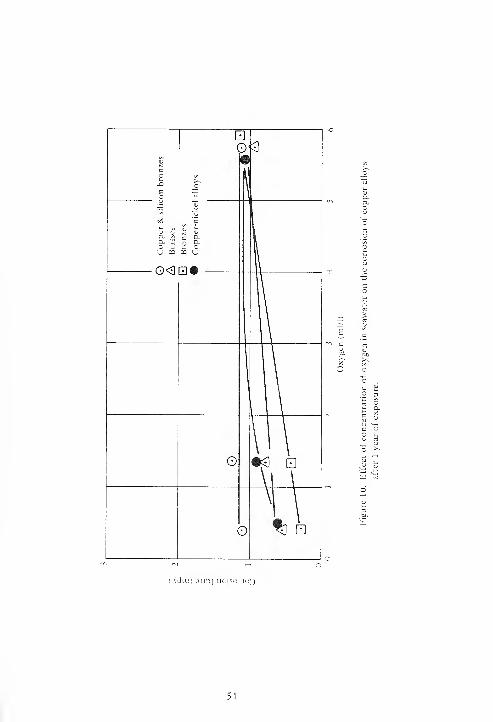
( \dui) oiv.\\ uoiso.uo;)
51

© - ao ^ vS
<U © DU O ,Jj
o j--o. w- ^
vO 6 <N c 3;u u.
t. B 1- P s-
<L) hi <L> S 3->
> " > *> >IS C/5 > LO >
•O
©•
-e- 5; oSO 3
00 • «[D
M—«-
01
(acJlu) .i:p>i uoisojjo'j
52
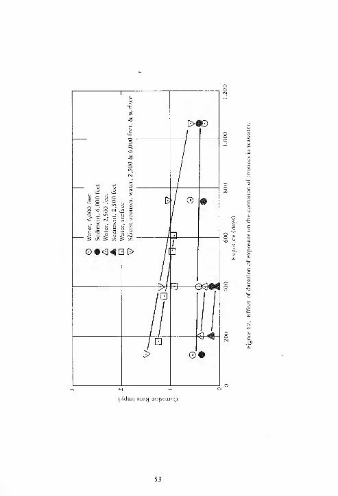
(A'dai) 3itf>j uoisojjrQ
53

<u Vq o
o oo +J"Ln ^ ^
\o c tM E</,
V E ft E uH -a t; -o rl
£ £ C/3 £
0#0«Q
(Xduj) 31B>J UOISCUJCQ
54

oo
-o—e-
(Xduj) airy uoisojjo^
55

(Xduj) 3}Ey uoisojjo3
56
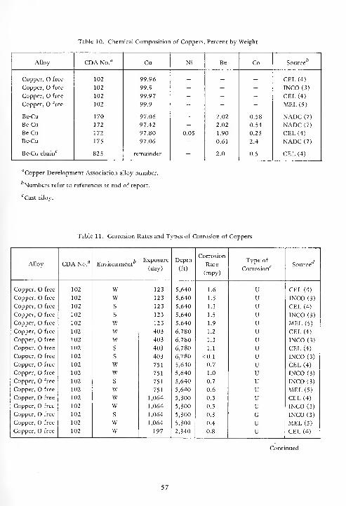
Table 10. Chemical Composition of Coppers, Percent by Weight
Alloy CDA No.13 Cu Ni Be Co c h
Source
Copper, free 102 99.96 _ _ _ CEL (4)
Copper, O free 102 99.9 - - - INCO (3)
Copper, O free 102 99.97 - - - CEL (4)
Copper, free 102 99.9 - - - MEL (5)
Be-Cu 170 97.06 - 2.02 0.58 NADC (7)
Be-Cu 172 97.42 - 2.02 0.54 NADC (7)
Be-Cu 172 97.80 0.05 1.90 0.25 CEL (4)
Be-Cu 175 97.06 - 0.61 2.4 NADC (7)
Be-Cu chainc
825 remainder - 2.0 0.5 CEL (4)
'Copper Development Association alloy number.
'Numbers refer to references at end of report.
:Cast alloy.
Table 11. Corrosion Rates and Types of Corrosion of Coppers
Alloy CDA No." EnvironmentExposure
(day)
Depth
(ft)
Corrosion
Rate
(mpy)
Type of
Corrosionc Source
Copper, O free 102 W 123 5,640 1.6 U CEL (4)
Copper, O free 102 W 123 5,640 1.5 U INCO (3)
Copper, O free 102 S 123 5,640 1.3 U CEL (4)
Copper, O free 102 S 123 5,640 1.5 u INCO (3)
Copper, O free 102 w 123 5,640 1.9 u MEL (5)
Copper, O free 102 w 403 6,780 1.2 u CEL (4)
Copper, O free 102 w 403 6,780 1.3 u INCO (3)
Copper, O free 102 s 403 6,780 1.1 u CEL (4)
Copper, O free 102 s 403 6,780 <0.1 u INCO (3)
Copper, O free 102 w 751 5,640 0.7 u CEL (4)
Copper, O free 102 w 751 5,640 1.0 u INCO (3)
Copper, O free 102 s 751 5,640 0.7 u INCO (3)
Copper, O free 102 w 751 5,640 0.6 u MEL (5)
Copper, O free 102 w 1,064 5,300 0.5 u CEL (4)
Copper, O free 102 w 1,064 5,300 0.5 u INCO (3)
Copper, O free 102 s 1,064 5,300 0.3 G INCO (3)
Copper, O free 102 w 1,064 5,300 0.4 u MEL (5)
Copper, O free 102 w 197 2,340 0.8 u CEL (4)
Continued
57
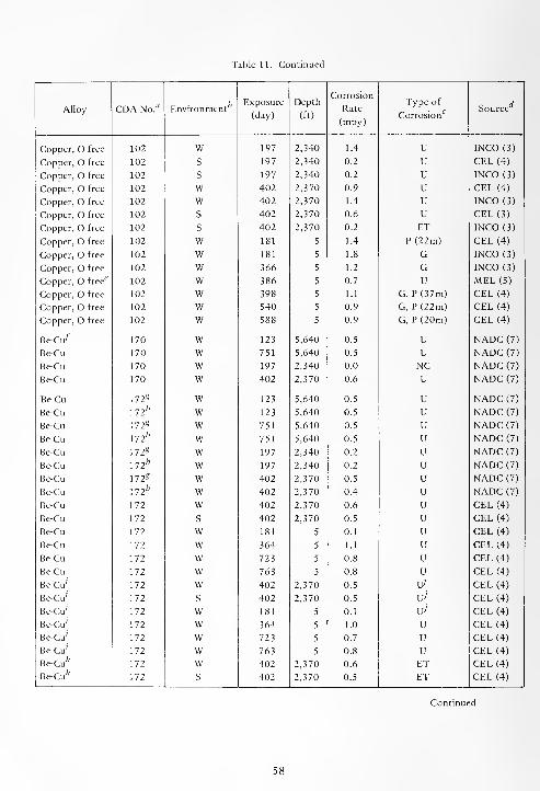
Table 11. Continued
Alloy CDA No." EnvironmentExposure
(day)
Depth
(ft)
Corrosion
Rate
(mpy)
Type of
Corrosion^Source
Copper, free 102 W 197 2,340 1.4 U INCO (3)
Copper, O free 102 S 197 2,340 0.2 U CEL (4)
Copper, free 102 S 197 2,340 0.2 u INCO (3)
Copper, O free 102 W 402 2,370 0.9 u CEL (4)
Copper, O free 102 w 402 2,370 1.4 u INCO (3)
Copper, O free 102 s 402 2,370 0.6 u CEL (3)
Copper, O free 102 s 402 2,370 0.2 ET INCO (3)
Copper, O free 102 w 181 5 1.4 P(22m) CEL (4)
Copper, free 102 w 181 5 1.8 G INCO (3)
Copper, free 102 w 366 5 1.2 G INCO (3)
Copper, O free^ 102 w 386 5 0.7 U MEL (5)
Copper, O free 102 w 398 5 1.1 G, P(37m) CEL (4)
Copper, free 102 w 540 5 0.9 G, P(22m) CEL (4)
Copper, free 102 w 588 5 0.9 G, P (20m) CEL (4)
Be-Cu^ 170 w 123 5,640 0.5 U NADC (7)
Be-Cu 170 w 751 5,640 0.5 U NADC (7)
Be-Cu 170 w 197 2,340 0.0 NC NADC (7)
Be-Cu 170 w 402 2,370 0.6 u NADC (7)
Be-Cu 172« w 123 5,640 0.5 u NADC (7)
Be-Cu 172h w 123 5,640 0.5 u NADC (7)
Be-Cu 172* w 751 5,640 0.5 u NADC (7)
Be-Cu 172fc w 751 5,640 0.5 u NADC (7)
Be-Cu 172* w 197 2,340 0.2 u NADC (7)
Be-Cu ll2h w 197 2,340 0.2 u NADC (7)
Be-Cu 172* w 402 2,370 0.5 u NADC (7)
Be-Cu 172* w 402 2,370 0.4 u NADC (7)
Be-Cu 172 w 402 2,370 0.6 u CEL (4)
Be-Cu 172 s 402 2,370 0.5 u CEL (4)
Be-Cu 172 w 181 5 0.1 u CEL (4)
Be-Cu 172 w 364 5 1.1 u CEL (4)
Be-Cu 172 w 723 5 0.8 u CEL (4)
Be-Cu 172 w 763 5 0.8 u CEL (4)
Be-Cu 172 w 402 2,370 0.5 \jj CEL (4)
Be-Cu 172 s 402 2,370 0.5 u' CEL (4)
Be-Cu 172 w 181 5 0.1 u' CEL (4)
Be-Cu 172 w 364 5 1.0 u CEL (4)
Be-Cu 172 w 723 5 0.7 u CEL (4)
Be-Cu' 172 w 763 5 0.8 u CEL (4)
Be-Cu* 172 w 402 2,370 0.6 ET CEL (4)
Be-Cu* 172 s 402 2,370 0.5 ET CEL (4)
Continued
58
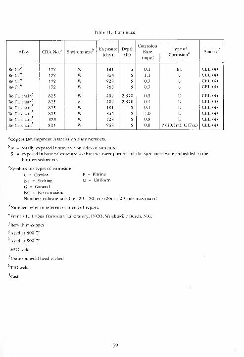
Table 11. Continued
Alloy CDA No.fl Environment
Exposure
(day)
Depth
(ft)
Corrosion
Rate
(mpy)
Type of
Corrosion'Source
Be-Cu* 172 W 181 5 0.1 ET CEL (4)
Be-Cu* 172 W 364 5 1.1 U CEL (4)
Be-Cu* 172 W 111 5 0.7 U CEL (4)
Be-Cu* 172 w 763 5 0.7 U CEL (4)
Be-Cu chain 825 w 402 2,370 0.5 U CEL (4)
Be-Cu chain 825 s 402 2,370 0.4 U CEL (4)
Be-Cu chain 825 w 181 5 0.1 u CEL (4)
Be-Cu chain 825 w 364 5 1.0 u CEL (4)
Be-Cu chain 825 w 723 5 0.8 u CEL (4)
Be-Cu chain 825 w 763 5 0.8 P (30.5m), C (7m) CEL (4)
''Copper Development Association alloy numbers.
W = totally exposed in seawater on sides of structure.
S = exposed in base of structure so that the lower portions of the specimens were embedded in the
bottom sediments.
c Symbols for types of corrosion:
C = Crevice P = Pitting
ET = Etching U = Uniform
G = General
NC = No corrosion
Numbers indicate mils (i.e., 20 = 20 mils; 20m = 20 mils maximum)
Numbers refer to references at end of report.
6Francis L. LaQue Corrosion Laboratory, INCO, Wrightsville Beach, N.C.
'Beryllium-copper
gAged at 600°F
^Agcd at 800°F
'MIG weld
•'Uniform, weld bead etched
*TIG weld
'Cast
59
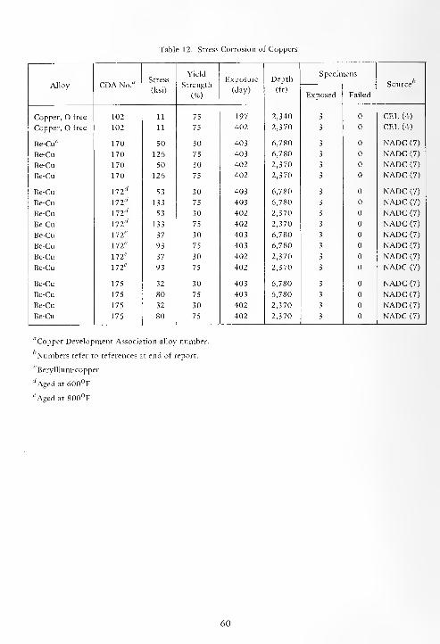
Table 12. Stress Corrosion of Coppers
Alloy CDA No."Stress
(ksi)
Yield
Strength
(%)
Exposure
(day)
Depth
(ft)
Specimensc bSource
Exposed Failed
Copper, free 102 11 75 197 2,340 3 CEL (4)
Copper, free 102 11 75 402 2,370 3 CEL (4)
Be-Cuc 170 50 30 403 6,780 3 NADC (7)
Be-Cu 170 126 75 403 6,780 3 NADC (7)
Be-Cu 170 50 30 402 2,370 3 NADC (7)
Be-Cu 170 126 75 402 2,370 3 NADC (7)
Be-Cu 172,V
53 30 403 6,780 3 NADC (7)
Be-Cu 172 rf133 75 403 6,780 3 NADC (7)
Be-Cu 172 tf53 30 402 2,370 3 NADC (7)
Be-Cu \12d
133 75 402 2,370 3 NADC (7)
Be-Cu \lle
37 30 403 6,780 3 NADC (7)
Be-Cu \lle
93 75 403 6,780 3 NADC (7)
Be-Cu m e37 30 402 2,370 3 NADC (7)
Be-Cu 172e
93 75 402 2,370 3 NADC (7)
Be-Cu 175 32 30 403 6,780 3 NADC (7)
Be-Cu 175 80 75 403 6,780 3 NADC (7)
Be-Cu 175 32 30 402 2,370 3 NADC (7)
Be-Cu 175 80 75 402 2,370 3 NADC (7)
"Copper Development Association alloy number.
Numbers refer to references at end of report.
cBeryllium-copper
rfAged at 600°F
*Aged at 800°F
60
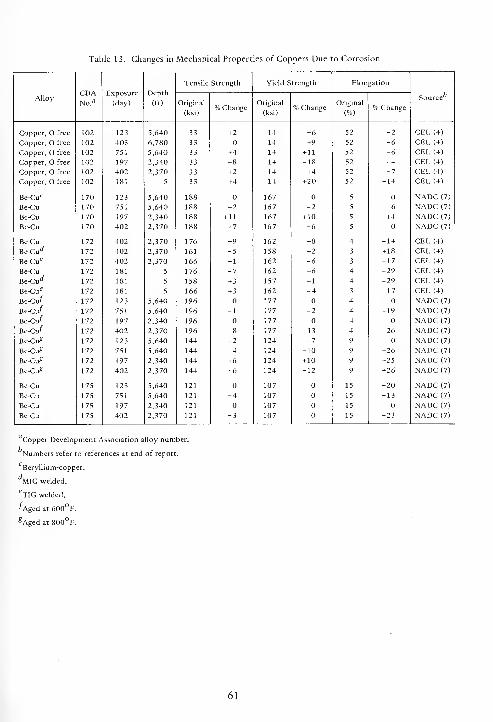
Table 13. Changes in Mechanical Properties of Coppers Due to Corrosion
CDANo."
Exposure
(day)
Depth
(ft)
Tensile Strength Yield Strength Elon Ration
AlloyOriginal
(ksi)% Change
Original
(ksi)% Change
Original
(%)% Change
Source''
Copper, O free 102 123 5,640 33 +2 14 -6 52 -2 CEL (4)
Copper, O free 102 403 6,780 33 14 +9 52 -6 CEL (4)
Copper, O free 102 751 5,640 33 +4 14 + 11 52 -6 CEL (4)
Copper, O free 102 197 2,340 33 -8 14 -18 52 -4 CEL (4)
Copper, O free 102 402 2,370 33 + 2 14 +4 52 -7 CEL (4)
Copper, free 102 181 5 33 +4 14 +20 52 -14 CEL (4)
Be-Cu 17 170 123 5,640 188 167 5 NADC (7)
Be-Cu 170 751 5,640 188 -2 167 _2 5 -6 NADC (7)
Be-Cu 170 197 2,340 188 + 11 167 + 10 5 + 4 NADC (7)
Be-Cu 170 402 2,370 188 -7 167 -6 5 NADC (7)
Be-Cu 172 402 2,370 176 -9 162 -8 4 -14 CEL (4)
Be-Cu** 172 402 2,370 161 -5 158 -2 3 + 18 CEL (4)
Be-Cu 17 172 402 2,370 166 -1 162 -6 3 -17 CEL (4)
Be-Cu 172 181 5 176 -7 162 -6 4 -29 CEL (4)
Be-Cud 172 181 5 158 + 3 157 -1 4 -29 CEL (4)
Be-Cu*7 172 181 5 166 + 3 162 -4 3 -17 CEL (4)
Be-Cu/ 172 123 5,640 196 177 4 NADC (7)
Be-Cu/ 172 751 5,640 196 -1 177 -2 4 -19 NADC (7)
Be-Cu/ 172 197 2,340 196 177 4 NADC (7)
Be-Cu/ 172 402 2,370 196 -8 177 -13 4 -26 NADC (7)
Be-Cu? 172 123 5,640 144 -2 124 -7 9 NADC (7)
Be-Cu? 172 751 5,640 144 -4 124 -10 9 +26 NADC (7)
Be-Cu? 172 197 2,340 144 +6 124 + 10 9 +25 NADC (7)
Be-Cu? 172 402 2,370 144 -6 124 -12 9 +26 NADC (7)
Be-Cu 175 123 5,640 121 107 15 -20 NADC (7)
Be-Cu 175 751 5,640 121 -4 107 15 -13 NADC (7)
Be-Cu 175 197 2,340 121 107 15 NADC (7)
Be-Cu 175 402 2,370 121 -3 107 15 -23 NADC (7)
Copper Development Association alloy numbe
Numbers refer to references at end of report.
Beryllium-copper.
MIG welded.
eTIG welded.
/Aged at 600° F.
?Aged at 800° F.
61
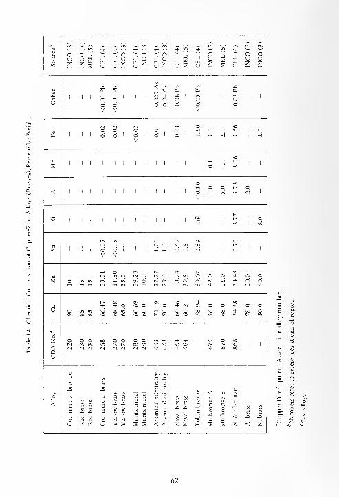
ro <N1
u * Tf Tf * * Th <d-
J-
3C
OUz
ouz w w
uwu
OUZ w
ouZ w
u
Ouz u
-JWu
Ouz W
U
ouz
Oz
<;<i
n X XCu Cu Cu Cu Cu
J=1
CM * on1 1 1
CM1 1
o o O o o o O oo o o o o o oV V V
o SO
Qj o o o o o f-1 o o so ofo 1 1 1 o o 1 o
Vo o CM
soc O os o Th m
o ro_ »-l o O r^ o< 1 1 l 1 1 1 1 1 1 1 o
Vin ~ CM
r»
z
,n o Os Os Oo O o o SO oo 00 r-
OO 1 oV
OV
o o o
o Os p~ •st- t-~ OOm o IN o r^ o t^ 00 o o O <* o oN o l
JJ . s « J^Os o r^ Os
CM00 Os Os CM
S eno o
t-~ on 0\ Os SO Tf 003 <* + o so o *—
<
o * CM Os o o u~i o oU © \r\ ITi SO 00 U"i O o ,-( o o o 00 SO CO •* CO o
Os oo oo SO so SO so so l~~ C^ so so " iy~> so " r^ "
6Z o o o co o o o o <* Tt- o OO
cm NO t^ r- oo no * * sn sn1
t~~ r^ SO1 1< cm CM CM cm CM CM "* <+ * ^- so SO co
QU
<u >s >^
c
x X H b
uc
<V
coX
VaF. T)
XI E
XI E
c
E
B
T3
CXI XI
coXGx
CQ
V
CoX
coXc
X X<u <U <U rt
u oi « u > >< § s < < z Z H § 1 Z < Z
62
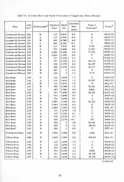
Table 15. Corrosion Rates and Types of Corrosion of Copper-Zinc Alloys (Brasses)
AlloyCDANo."
EnvironmentExposure
(day)
Depth
(ft)
Corrosion
Rate
(mpy)
Type of
Corrosion"7
Source
Commercial Bronze 220 W 123 5,640 0.6 U INCO (3)
Commercial Bronze 220 S 123 5,640 0.3 U INCO (3)
Commercial Bronze 220 W 403 6,780 0.6 U INCO (3)
Commercial Bronze 220 S 403 6,780 <0.1 u INCO (3)
Commercial Bronze 220 W 751 5,640 0.6 C(9) INCO (3)
Commercial Bronze 220 S 751 5,640 0.4 C(20) INCO (3)
Commercial Bronze 220 W 1,064 5,300 0.4 C(20) INCO (3)
Commercial Bronze 220 S 1,064 5,300 0.6 U INCO (3)
Commercial Bronze 220 W 197 2,340 0.3 U INCO (3)
Commercial Bronze 220 S 197 2,340 0.1 NU-ET INCO (3)
Commercial Bronze 220 W 402 2,370 0.2 SL-DZ INCO (3)
Commercial Bronze 220 S 402 2,370 <0.1 SL-DZ INCO (3)
Commercial Bronze 220 W 181 5 1.1 U INCO (3)
Commercial Bronze 220 W 366 5 1.1 P(4) INCO (3)
Red Brass 230 W 123 5,640 1.3 U INCO (3)
Red Brass 230 S 123 5,640 1.7 SL-DZ INCO (3)
Red Brass 230 W 123 5,640 1.9 V MEL (5)
Red Brass 230 W 403 6,780 1.2 SL-DZ INCO (3)
Red Brass 230 S 403 6,780 0.4 GBSL INCO (3)
Red Brass 230 W 751 5,640 0.9 SL-DZ UNCO (3)
Red Brass 230 S 751 5,640 0.7 U INCO (3)
Red Brass 230 W 751 5,640 0.7 u MEL (5)
Red Brass 230 W 1,064 5,300 0.6 SL-DZ INCO (3)
Red Brass 230 s 1,064 5,300 0.3 G INCO (3)
Red Brass 230 w 1,064 5,300 0.6 U MEL (5)
Red Brass 230 w 197 2,340 1.0 u INCO (3)
Red Brass 230 s 197 2,340 0.1 u INCO (3)
Red Brass 230 w 402 2,370 0.7 u INCO (3)
Red Brass 230 s 402 2,370 <0.1 ET INCO (3)
Red Brass 230 w 181 5 1.8 SL-DZ INCO (3)
Red Brass 230 w 366 5 1.2 CR(6) INCO (3)
Red Brass" 230 w 386 5 0.8 U MEL (5)
Commercial Brass 268 w 1,064 5,300 0.8 S-DZ CEL (4)
Yellow Brass 268 w 1,064 5,300 0.6 MO-DZ CEL (4)
Yellow Brass 270 w 123 5,640 1.4 U INCO (3)
Yellow Brass 270 s 123 5,640 1.3 u INCO (3)
Yellow Brass 270 w 403 6,780 1.0 u INCO (3)
Yellow Brass 270 s 403 6,780 0.2 GBSL INCO (3)
Yellow Brass 270 w 751 5,640 2.5 SL-DZ INCO (3)
Yellow Brass 270 s 751 5,640 0.6 SL-DZ INCO (3)
Continued
63
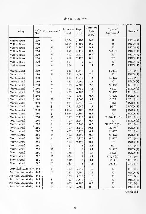
Table 15. Continued.
AlloyCDANo."
EnvironmentExposure
(day)
Depth
(ft)
Corrosion
Rate
(mpy)
Type of
Corrosionc Source
Yellow Brass 270 W 1,064 5,300 0.6 U INCO (3)
Yellow Brass 270 S 1,064 5,300 0.5 U INCO(3)
Yellow Brass 270 W 197 2,340 0.9 U INCO (3)
Yellow Brass 270 s 197 2,340 0.2 NU-ET INCO (3)
Yellow Brass 270 w 402 2,370 0.9 U INCO (3)
Yellow Brass 270 s 402 2,370 0.1 ET INCO (3)
Yellow Brass 270 w 181 5 2.1 U INCO (3)
Yellow Brass 270 w 366 5 1.3 U INCO (3)
Muntz Metal 280 w 123 5,640 1.6 SL-DZ CEL (4)
Muntz Metal 280 w 123 5,640 2.1 U INCO (3)
Muntz Metal 280 s 123 5,640 1.3 SL-DZ CEL (4)
Muntz Metal 280 s 123 5,640 1.5 U INCO (3)
Muntz Metal 280 w 403 6,780 2.6 SL-DZ CEL (4)
Muntz Metal 280 w 403 6,780 3.3 S-DZ INCO (3)
Muntz Metal 280 s 403 6,780 1.8 SL-DZ CEL (4)
Muntz Metal 280 s 403 6,780 0.6 GBSL INCO (3)
Muntz Metal 280 w 751 5,640 3.2 G-DZ CEL (4)
Muntz Metal 280 w 751 5,640 4.0 S-DZ INCO (3)
Muntz Metal 280 s 751 5,640 1.7 S-DZ INCO (3)
Muntz Metal 280 w 1,064 5,300 2.3 S-DZ INCO (3)
Muntz Metal 280 s 1,064 5,300 0.8 U INCO (3)
Muntz Metal 280 w 197 2,340 0.7 SL-DZ; P (10) CEL (4)
Muntz Metal 280 w 197 2,340 0.7 U INCO (3)
Muntz Metal 280 s 197 2,340 0.5 SL-DZ; P (5) CEL (4)
Muntz Metal 280 s 197 2,340 <0.1 SL-DZ^ INCO (3)
Muntz Metal 280 w 402 2,370 0.7 SL-DZ CEL (4)
Muntz Metal 280 w 402 2,370 0.7 SL-DZ INCO (3)
Muntz Metal 280 s 402 2,370 0.6 SL-DZ CEL (4)
Muntz Metal 280 s 402 2,370 0.1 ET INCO (3)
Muntz Metal 280 w 181 5 2.4 DZ CEL (4)
Muntz Metal 280 w 181 5 3.4 SL-DZ INCO (3)
Muntz Metal 280 w 366 5 3.7 S-DZ INCO (3)
Muntz Metal 280 w 398 5 3.1 DZ, P(6) CEL (4)
Muntz Metal 280 w 540 5 3.4 DZ, IP CEL (4)
Muntz Metal 280 w 588 5 3.3 DZ, I-P CEL (4)
Arsenical Admiralty 443 w 123 5,640 1.0 U CEL (4)
Arsenical Admiralty 443 w 123 5,640 1.1 u INCO (3)
Arsenical Admiralty 443 s 123 5,640 1.0 u CEL (4)
Arsenical Admiralty 443 s 123 5,640 1.0 u INCO (3)
Arsenical Admiralty 443 w 403 6,780 0.7 u CEL (4)
Arsenical Admiralty 443 w 403 6,780 0.8 u INCO (3)
Continued
64

Table 15. Continued.
AlloyCDANo."
EnvironmentExposure
(day)
Depth
(ft)
Corrosion
Rate
(mpy)
Type of
Corrosionc
c dSource
Arsenical Admiralty 443 S 403 6,780 0.8 U CEL (4)
Arsenical Admiralty 443 S 403 6,780 0.2 GBSL INCO (3)
Arsenical Admiralty 443 W 751 5,640 0.6 U CEL (4)
Arsenical Admiralty 443 W 751 5,640 0.7 U INCO (3)
Arsenical Admiralty 443 S 751 5,640 0.4 u CEL (4)
Arsenical Admiralty 443 S 751 5,640 0.5 u INCO (3)
Arsenical Admiralty 443 W 1,064 5,300 0.5 u INCO (3)
Arsenical Admiralty 443 S 1,064 5,300 0.5 u INCO (3)
Arsenical Admiralty 443 W 197 2,340 0.6 u CEL (4)
Arsenical Admiralty 443 W 197 2,340 1.0 u INCO (3)
Arsenical Admiralty 443 S 197 2,340 0.2 u CEL (4)
Arsenical Admiralty 443 S 197 2,340 <0.1 u INCO (3)
Arsenical Admiralty 443 W 402 2,370 0.6 u CEL (4)
Arsenical Admiralty 443 W 402 2,370 0.6 u INCO (3)
Arsenical Admiralty 443 S 402 2,370 0.4 u CEL (4)
Arsenical Admiralty 443 s 402 2,370 0.1 ET INCO (3)
Arsenical Admiralty 443 w 181 5 1.3 U CEL (4)
Arsenical Admiralty 443 w 181 5 1.8 G INCO (3)
Arsenical Admiralty 443 w 366 5 1.3 u INCO (3)
Arsenical Admiralty 443 w 608 5 1.1 U;l-P CEL (4)
Naval Brass 464 w 123 5,640 1.2 U MEL (5)
Naval Brass 464 w 751 5,640 0.6 U MEL (5)
Naval Brass 464 w 1,064 5,300 0.7 U MEL (5)
Naval Brass 464 w 1,064 5,300 1.0 S-DZ CEL (4)
Naval Brass17 464 w 364 5 0.7 u MEL (5)
Tobin Bronze - w 1,064 5,300 0.9 S-DZ CEL (4)
Mn Bronze A 675 w 123 5,640 2.9 EX-DZ INCO (3)
Mn Bronze A 675 s 123 5,640 2.0 EX-DZ INCO (3)
Mn Bronze A 675 w 403 6,780 2.7 S-DZ INCO (3)
Mn Bronze A 675 s 403 6,780 0.9 S-DZ INCO (3)
Mn Bronze A 675 w 751 5,640 7.2 S-DZ INCO (3)
Mn Bronze A 675 s 751 5,640 2.6 V-S-DZ INCO (3)
Mn Bronze A 675 w 1,064 5,300 2.0 S-DZ INCO (3)
Mn Bronze A 675 s 1,064 5,300 1.2 S-DZ INCO (3)
Mn Bronze A 675 w 197 2,340 1.2 S-DZ INCO (3)
Mn Bronze A 675 s 197 2,340 0.2 SL-DZ INCO (3)
Mn Bronze A 675 w 402 2,370 0.8 S-DZ INCO (3)
Mn Bronze A 675 s 402 2,370 <0.1 SL-DZ INCO (3)
Mn Bronze A 675 w 181 5 4.8 S-DZ INCO (3)
Mn Bronze A 675 w 366 5 1.9 S-DZ INCO (3)
Continued
65
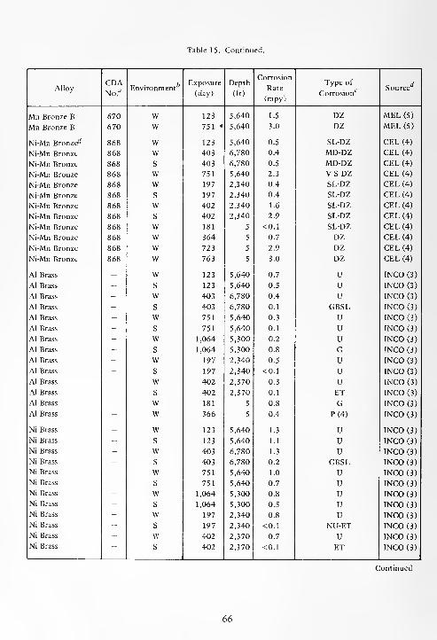
Table 15. Continued.
AlloyCDANo.
flEnvironment
Exposure
(day)
Depth
(ft)
Corrosion
Rate
(mpy)
Type of
Corrosion"7
Source
Mn Bronze B 670 W 123 5,640 1.5 DZ MEL (5)
Mn Bronze B 670 W 751 * 5,640 3.0 DZ MEL (5)
Ni-Mn Bronze^ 868 W 123 5,640 0.5 SL-DZ CEL (4)
Ni-Mn Bronze 868 W 403 6,780 0.4 MD-DZ CEL (4)
Ni-Mn Bronze 868 S 403 6,780 0.5 MD-DZ CEL (4)
Ni-Mn Bronze 868 w 751 5,640 2.3 V-S-DZ CEL (4)
Ni-Mn Bronze 868 w 197 2,340 0.4 SL-DZ CEL (4)
Ni-Mn Bronze 868 s 197 2,340 0.4 SL-DZ CEL (4)
Ni-Mn Bronze 868 w 402 2,340 1.6 SL-DZ CEL (4)
Ni-Mn Bronze 868 s 402 2,340 2.9 SL-DZ CEL (4)
Ni-Mn Bronze 868 w 181 5 <0.1 SL-DZ CEL (4)
Ni-Mn Bronze 868 w 364 5 0.7 DZ CEL (4)
Ni-Mn Bronze 868 w 723 5 2.9 DZ CEL (4)
Ni-Mn Bronze 868 w 763 5 3.0 DZ CEL (4)
Al Brass - w 123 5,640 0.7 U INCO (3)
Al Brass - s 123 5,640 0.5 u INCO (3)
Al Brass - w 403 6,780 0.4 u INCO (3)
AJ Brass - s 403 6,780 0.1 GBSL INCO (3)
Al Brass - w 751 5,640 0.3 U INCO (3)
Al Brass - s 751 5,640 0.1 U INCO (3)
Al Brass - w 1,064 5,300 0.2 u INCO (3)
Al Brass - s 1,064 5,300 0.8 G INCO (3)
Al Brass - w 197 2,340 0.5 U INCO (3)
Al Brass - s 197 2,340 <0.1 u INCO (3)
Al Brass - w 402 2,370 0.3 u INCO (3)
Al Brass - s 402 2,370 0.1 ET INCO (3)
Al Brass - w 181 5 0.8 G INCO (3)
Al Brass - w 366 5 0.4 P(4) INCO (3)
Ni Brass - w 123 5,640 1.3 U INCO (3)
Ni Brass - s 123 5,640 1.1 U INCO (3)
Ni Brass - w 403 6,780 1.3 U INCO (3)
Ni Brass - s 403 6,780 0.2 GBSL INCO (3)
Ni Brass - w 751 5,640 1.0 U INCO (3)
Ni Brass - s 751 5,640 0.7 u INCO (3)
Ni Brass - w 1,064 5,300 0.8 u INCO (3)
Ni Brass - s 1,064 5,300 0.5 u INCO (3)
Ni Brass - w 197 2,340 0.8 u INCO (3)
Ni Brass - s 197 2,340 <0.1 NU-ET INCO (3)
Ni Brass - w 402 2,370 0.7 U INCO (3)
Ni Brass — s 402 2,370 <0.1 ET INCO (3)
Continued
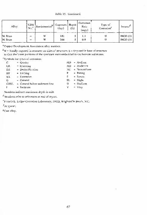
Table 15. Continued.
AlloyCDANo."
EnvironmentExposure
(day)
Depth
(ft)
Corrosion
Rate
(mpy)
Type of
Corrosionc Source
Ni Brass
Ni Brass -WW
181
366
5
5
1.1
0.9
UU
INCO (3)
INCO (3)
"Copper Development Association alloy number.
W = Totally exposed in seawater on sides of structure; S = Exposed in base of structure
so that the lower portions of the specimen were embedded in the bottom sediments.
^Symbols for types of corrosion:
C = Crevice
CR = Cratering
DZ = Dezincification
ET = Etching
EX = Extensive
G = General
GBSL = General below sediment line
I = Incipient
Numbers indicate maximum depth in mils.
Numbers refer to references at end of report.
6Francis L. LaQue Corrosion Laboratory, INCO, Wrightsville Beach, N.C.
"At spacer.
^Cast alloy.
MD = Medium
MO = Moderate
NU = Nonuniform
P = Pitting
S = Severe
SL = Slight
U = Uniform
V = Very
67
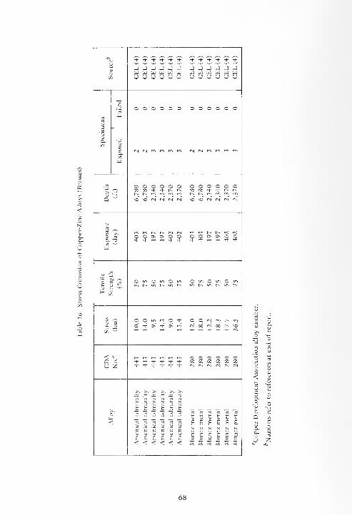
-a * •* * * + Tf <* -t "T -t- -* It-
u3o
J J J -J J -1 J J J j J Jtd tt) td td td td td td td td td td
CO U U U U O O CJ O O U U U
-a<u OOOOOO O O O O O Oa,
c
E5O- -0
00 VO rs! (Ma.Xw
-C OOOOOO O O O O OO- 3 00 00 * * 1^ N 00 00 -t- <* r-- r-
r^ l^ m ro rri rr, r^ c^ mQ "" VO NO N N N N so SO <N <M r-i (N
u
3 >, rr. m r-. r- (N r*l m t^ t^ rsi r-j
O d O O On Os O O s O Os Os O OO. T3 + + H H + + <+ -+ -*• <*X -'
td
QJ "^~ bo ^-v<2 c -^ O m O in O in O 101 O 101 O mc hj S^ r^ r~ in r^gj ^- '
^ £
u '55O O in m Tf- O r- in
O •+ OS <* Ox rr, CM 00 rsi 00 t^ so
COw
< «. O O O O O OQ t(- •*- rt- Th •* Tt- 00 00 00 00 00 00
U Z ^ Ij- * * ^ + <M rsi Csl rsi (N
>, >^ ^ >^ >, >^
rt rt rt rt aj aj
E E E E £ E>. -a -0 -a -0 T3 -a rt ~. rt rt
V (L) u< U U U U O CJ
E E E E E E
c c c c c c1U (U QJ OJ (U U c c c c c c
3 3 3 3 3 3<<<<<< § S S § § s

a * * -1- -t- -1- d- * -d- -d- -d- * t)- <* •+ -i- ^h 'd- ^d-
i J J J - _ J J J J J J J J J J J -J Jo w W U3 w w W [13 W W W Hi W W w w W W [i3
co u u cj u u CJ U U CJ U CJ u u u U CJ CJ
OJ
bo
no no N H H ffl H (N 00 NO1
FN) 1 + + 1 1H NO NO rn
co U 1 1 1 1 1 + 1 1 + 1 1
zz ^rtbocoH
6~ £ 5 5 JJ in K NO NO NO no NO no
NO NO NO NO NO NO (Nc ~ O O
cubo
j=.C
rrt CM >. W ^i H H ffl O 00 T-H t~~ in-, ^d-
1 <n + 1 1 N 1 rl1
<NbOc <j 1 1 1 1 1 1 1 1 1 1 + +
o ^t/J
"u c .0'm JJ
* ^d- •d- -d- •d- * On On On On On On<N CnI cn tN
O
bo_c
c3 d- no (N no 00 t-~ O <N rvl no cn CN rNi m rr> NO OSi) J3 1 1 1 1 1 1 1 1 1 1 "* 1
c U<u
enCJ
'<st "rtc c aCJ no O NO NOH
O """
t>- t--. t-^ r- 1^
O O _ m O O O O O in O O O O in
O. £ <d- 00 -t" 4 r^ d- 00 00 -d- r- -1- 00 -t- -1- r^NO t-^ NO m m no l> no rn rn nO t-~ NO rr> m
Cjv"
in NO in <N cnI in vo in N IN| in NO in N CN
3 •—
-
t^ CN t~. (N rt3 rt (N O O O 00 CnI O in On O CO M On O 001. T3 * t"^ -T — -t f~ T-H -d- .H •+ t-. + i-H
-< -^Va
< °. O O O O O O ^ ^ ^ ^ ^ ^ 00 00 00 00 00 00I3 oc 00 cc 00 oc 00 d- -d- -d- rl- •* •+ NO NO NO NO NO
J Z <n (N C-l IS (N CN d- -d- <d- rt- rt- •* 00 00 00 00 00 00
>. >~. ^ >> >> >^
<u u OJ OJ OJ CJE E E E £ Eg' m -. rd ED M rd -a -a -a -0 -a -a c b c a c c
V CJ CJ CJ CJ
*£ E £ £ E "rt "rt "rt "rt "rt "rtO V CJ CJ u u J3 JO XI JO JO JO
N N f) N N N'E '£ 'c '5 'E '£ c e c c c c
C c c c c c CD CJ CJ CJ flj OJ s ^ s < s §3 3 3 3
* « £ S s £ <<<<<< Z Z Z Z Z z
69
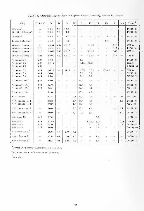
Table 18. Chemical Composition of Copper Alloys (Bronzes), Percent by Weight
Alloy
G bronze
Modified G bronze
M bronze
Leaded Sn bronze
Phosphor bronze APhosphor bronze APhosphor bronze A
Phosphor bronze D
Al bronze, 5%Al bronze, 5%Al bronze, 5%
Al bronze, 7%Al bronze, 7%Al bronze, 7%
Al bronze, 10%
Al bronze, 11%Al bronze, 11%
Al bronze, 13% c
Ni-Al bronze
Ni-Al bronze No. 1
Ni-Al bronze No. 1
Ni-Al bronze No. 2
Ni-Al bronze No. 3
Si bronze, 3%
Si bronze ASi bronze ASi bronze A
Ni-Vee bronze A
Ni-Vee bronze B
Ni-Vee bronze C
510
510
510
524
606
606
606
614
614
614
954
954
655
655
655
88.0
88.0
88.2
85.0
94.64
96.0
95.62
90.00
95.0
95.11
90.11
90.0
86.0
86.5
83.0
83.5
80.0
80.0
80.0
80.0
97.0
95.49
95.0
96.0
88.0
87.0
80.0
2.0
8.0
6.0
5.0
4.94
4.0
4.44
9.23
10.0
4.0
4.0
5.0
<0.10
<0.10
<0.10
2.0
5.0
<0.05
<0.05
0.26
0.25
0.06
0.17
5.0
4.76
2.0
2.0
5.0
6.59
7.0
9.0
10.0
10.0
10.0
13.0
10.0
11.0
10.0
10.0
9.0
3.15
3.0
3.0
1.0
4.0
3.5
4.0
4.0
4.0
4.0
4.0
3.5
3.0
3.28
3.0
3.0
0.5
3.0
INCO (3)
INCO (3)
INCO (3)
INCO (3)
CEL (4)
INCO (3)
CEL (4)
CEL (4)
INCO (3)
CEL (4)
Boeing (6)
CEL (4)
INCO (3)
NADC (7)
INCO (3)
INCO (3)
MEL (5)
INCO (3)
MEL (5)
INCO (3)
MEL (5)
INCO (3)
INCO (3)
INCO (3)
CEL (4)
INCO (3)
Boeing (6)
INCO (3)
INCO (3)
INCO (3)
Copper Development Association alloy number.
Numbers refer to references at end of report.
Cast alloy.
70

Table 19. Corrosion Rates and Types of Corrosion of Copper Alloys (Bronzes)
AlloyCDA
EnvironmentExposure Depth
Corrosion
RateType of
SourceNo.a (day) (ft)
(mpy)Corrosionc
G Bronze - W 123 5,640 0.5 U INCO (3)
G Bronze - S 123 5,640 0.3 U INCO (3)
G Bronze - W 403 6,780 0.7 u INCO (3)
G Bronze - S 403 6,780 0.1 GBSL INCO (3)
G Bronze - W 751 5,640 0.7 U INCO (3)
G Bronze - S 751 5,640 0.3 U INCO (3)
G Bronze - W 1,064 5,300 0.3 U INCO (3)
G Bronze - S 1,064 5,300 0.4 U INCO (3)
G Bronze - W 197 2,340 0.2 U .NCO (3)
G Bronze - S 197 2,340 <0.1 I-C INCO (3)
G Bronze - W 402 2,370 0.3 u INCO (3)
G Bronze - s 402 2,370 <0.1 ET INCO (3)
G Bronze - w 181 5 1.3 G INCO (3)
G Bronze - w 366 5 1.2 CR(9) INCO (3)
Modified G Bronze - w 123 5,640 0.5 U INCO (3)
Modified G Bronze - s 123 5,640 0.3 u INCO (3)
Modified G Bronze - w 403 6,780 0.4 u INCO (3)
Modified G Bronze - s 403 6,780 <0.1 u INCO (3)
Modified G Bronze - w 751 5,640 0.7 u INCO (3)
Modified G Bronze - s 751 5,640 0.4 C(19) INCO (3)
Modified G Bronze - w 1,064 5,300 0.4 C(18);P INCO (3)
Modified G Bronze - s 1,064 5,300 0.5 U INCO (3)
Modified G Bronze - w 197 2,340 0.3 U INCO (3)
Modified G Bronze - s 197 2,340 0.2 NU-ET INCO (3)
Modified G Bronze - w 402 2,370 0.3 U INCO (3)
Modified G Bronze - s 402 2,370 <0.1 ET INCO (3)
Modified G Bronze - w 181 5 1.3 G INCO (3)
Modified G Bronze - w 366 5 1.0 CR(7) INCO (3)
M Bronze - w 123 5,640 0.5 U INCO (3)
M Bronze - s 123 5,640 0.4 U INCO (3)
M Bronze - w 403 6,780 0.4 U INCO (3)
M Bronze - s 403 6,780 <0.1 U INCO (3)
M Bronze - w 751 5,640 0.7 U INCO (3)
M Bronze - s 751 5,640 0.3 U INCO (3)
M Bronze - w 1,064 5,300 0.4 U INCO (3)
M Bronze - s 1,064 5,300 0.4 U INCO (3)
M Bronze - w 197 2,340 0.4 U INCO (3)
M Bronze - s 197 2,340 0.1 ET INCO (3)
M Bronze - w 402 2,370 0.3 U INCO (3)
M Bronze - s 402 2,370 <0.1 ET INCO (3)
M Bronze - w 181 5 1.6 G INCO (3)
M Bronze - w 366 5 1.1 CR(2) INCO (3)
Leaded Sn Bronze - w 123 5,640 0.4 U INCO (3)
Leaded Sn Bronze - s 123 5,640 0.2 U INCO (3)
Leaded Sn Bronze - w 403 6,780 0.5 U INCO (3)
Leaded Sn Bronze - s 403 6,780 0.1 U INCO (3)
Leaded Sn Bronze - w 751 5,640 0.6 U INCO (3)
Leaded Sn Bronze - s 751 5,640 3.2 S-G INCO (3)
Leaded Sn Bronze — w 1,064 5,300 0.4 U INCO (3)
71

Table 19. Continued.
Corrosion
AlloyCDA
EnvironmentExposure Depth
RateType of
SourceNo." (day) (ft)
(mpy)Corrosion 17
Leaded Sn Bronze - S 1,064 5,300 0.3 U INCO (3)
Leaded Sn Bronze - W 197 2,340 0.5 u 1NCO (3)
Leaded Sn Bronze - S 197 2,340 <0.1 NU-ET INCO (3)
Leaded Sn Bronze - W 402 2,370 0.5 U INCO (3)
Leaded Sn Bronze - S 402 2,370 <0.1 ET INCO (3)
Leaded Sn Bronze - W 181 5 1.4 G INCO (3)
Leaded Sn Bronze - W 366 5 1.3 CR(5) INCO (3)
P Bronze A 510 W 123 5,640 0.6 U CEL (4)
P Bronze A 510 W 123 5,640 0.5 U INCO (3)
P Bronze A 510 S 123 5,640 0.4 u CEL (4)
P Bronze A 510 s 123 5,640 0.4 u INCO (3)
P Bronze A 510 w 403 6,780 0.2 ET CEL (4)
P Bronze A 510 w 403 6,780 0.3 U INCO (3)
P Bronze A 510 s 403 6,780 0.3 ET CEL (4)
P Bronze A 510 s 403 6,780 0.1 GBSL INCO (3)
P Bronze A 510 w 751 5,640 0.2 ET CEL (4)
P Bronze A 510 w 751 5,640 0.3 U INCO (3)
P Bronze A 510 s 751 5,640 0.1 U INCO (3)
P Bronze A 510 w 1,064 5,300 0.4 U CEL (4)
P Bronze A 510 w 1,064 5,300 0.2 U INCO (3)
P Bronze A 510 s 1,064 5,300 0.4 G INCO (3)
P Bronze A 510 w 197 2,340 0.3 U CEL (4)
P Bronze A 510 w 197 2,340 0.4 U INCO (3)
P Bronze A 510 s 197 2,340 0.3 / CEL (4)
P Bronze A 510 s 197 2,340 <0.1 I-C INCO (3)
P Bronze A 510 w 402 2,370 0.1 ET CEL (4)
P Bronze A 510 w 402 2,370 0.2 U INCO (3)
P Bronze A 510 s 402 2,370 0.2 EWO CEL (4)
P Bronze A 510 s 402 2,370 0.2 ET INCO (3)
P Bronze A 510 w 181 5 1.1 U CEL (4)
P Bronze A 510 w 181 5 1.6 P(4) INCO (3)
P Bronze A 510 w 366 5 1.3 CR(5) INCO (3)
P Bronze A 510 w 588 5 1.3 CR(15);C(3) CEL (4)
P Bronze A 510 w 608 5 1.1 CR(15) CEL (4)
P Bronze D 524 w 123 5,640 0.5 U CEL (4)
P Bronze D 524 s 123 5,640 0.4 U CEL (4)P Bronze D 524 w 403 6,780 0.2 ET CEL (4)P Bronze D 524 s 403 6,780 0.3 ET CEL (4)P Bronze D 524 w 751 5,640 0.3 U CEL (4)P Bronze D 524 s 751 5,640 0.4 NU CEL (4)P Bronze D 524 w 197 2,340 0.4 U CEL (4)P Bronze D 524 s 197 2,340 0.2 U CEL (4)P Bronze D 524 w 402 2,370 <0.1 U CEL (4)P Bronze D 524 s 402 2,370 <0.1 U CEL (4)P Bronze D 524 w 181 5 1.1 NU CEL (4)P Bronze D 524 w 398 5 0.9 CR(4) CEL (4)P Bronze D 524 w 540 5 0.7 CR(2) CEL (4)P Bronze D 524 w 608 5 0.7 CR(7);C (5) CEL (4)
Al Bronze, 5% 606 w 123 5,640 0.6 U INCO (3)Al Bronze, 5% 606 s 123 5,640 0.4 U INCO (3)
72
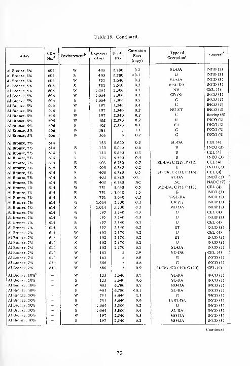
Table 19. Continued.
1 Corrosion
AlloyCDANo. fl
EnvironmentExposure
(day)
Depth
(ft)Rate
(mpy)
Type of
Corrosion*7Source
Al Bronze, 5% 606 W 403 6,780 0.2 SL-DA INCO (3)
Al Bronze, 5% 606 S 403 6,780 <0.1 U INCO (3)
Al Bronze, 5% 606 w 751 5,640 0.3 SL-DA INCO (3)
Al Bronze, 5% 606 s 751 5,640 0.2 V-SL-DA INCO (3)
Al Bronze, 5% 606 w 1,064 5,300 0.2 NU CEL (4)
Al Bronze, 5% 606 w 1,064 5,300 0.2 CR(5) INCO (3)
Al Bronze, 5% 606 s 1,064 5,300 0.5 G INCO (3)
Al Bronze, 5% 606 w 197 2,340 0.4 U INCO (3)
Al Bronze, 5% 606 s 197 2,340 0.2 NU-ET INCO (3)
Al Bronze, 5% 606 w 197 2,340 0.2 U Boeing (6)
Al Bronze, 5% 606 w 402 2,370 0.2 U INCO (3)
Al Bronze, 5% 606 s 402 2,370 0.1 ET INCO (3)
Al Bronze, 5% 606 w 181 5 1.1 G INCO (3)
Al Bronze, 5% 606 w 366 5 0.7 G INCO (3)
Al Bronze, 7% 614 123 5,640 0.5 SL-DA CEL (4)
Al Bronze, 7% 614 w 123 5,640 0.6 U INCO (3)
Al Bronze, 7% 614 s 123 5,640 0.3 U CEL (4)
Al Bronze, 7% 614 s 123 5,640 0.4 U INCO (3)
Al Bronze, 7% 614 w 403 6,780 0.7 SL-DAiC (12); P (12) CEL (4)
Al Bronze, 7% 614 w 403 6,780 0.2 U INCO (3)
Al Bronze, 7% 614 s 403 6,780 0.7 SL-DA;C (13); P (16) CEL (4)
Al Bronze, 7% 614 s 403 6,780 <0.1 SL-DA INCO (3)
Al Bronze, 7% 614 w 403 6,780 NC NC NADC (7)
Al Bronze, 7% 614 w 751 5,640 0.5 MD-DA;C(7);P(12) CEL (4)
Al Bronze, 7% 614 w 751 5,640 1.5 G INCO (3)
Al Bronze, 7% 614 s 751 5,640 0.2 V-SL-DA INCO (3)
Al Bronze, 7% 614 w 1,064 5,300 0.2 CR(7) INCO (3)
Al Bronze, 7% 614 s 1,064 5,300 0.2 MO-DA INCO (3)
Al Bronze, 7% 614 w 197 2,340 0.3 U CEL (4)
Al Bronze, 7% 614 w 197 2,340 0.3 u INCO (3)
Al Bronze, 7% 614 s 197 2,340 0.1 u CEL (4)
Al Bronze, 7% 614 s 197 2,340 0.2 ET INCO (3)
Al Bronze, 7% 614 w 402 2,370 0.2 U CEL (4)
Al Bronze, 7% 614 w 402 2,370 0.2 ET INCO (3)
Al Bronze, 7% 614 s 402 2,370 0.2 U INCO (3)
Al Bronze, 7% 614 s 402 2,370 0.1 SL-DA INCO (3)
Al Bronze, 7% 614 w 181 5 2.9 NU-DA CEL (4)
Al Bronze, 7% 614 w 181 5 0.8 G INCO (3)
Al Bronze, 7% 614 w 366 5 0.6 G INCO (3)
Al Bronze, 7% 614 w 588 5 0.9 SL-DA; CR (44); C (20) CEL (4)
Al Bronze, 10%^ - w 123 5,640 0.7 SL-DA INCO (3)
Al Bronze, 10% - s 123 5,640 0.6 SL-DA INCO (3)
Al Bronze, 10% - w 403 6,780 0.7 MO-DA INCO (3)
Al Bronze, 10% - s 403 6,780 <0.1 SL-DA INCO (3)
Al Bronze, 10% - w 751 5,640 2.3 G INCO (3)
Al Bronze, 10% - s 751 5,640 0.9 U; SL-DA INCO (3)
Al Bronze, 10% - w 1,064 5,300 0.2 U INCO (3)
Al Bronze, 10% - s 1,064 5,300 0.4 SL-DA INCO (3)
Al Bronze, 10% - w 197 2,340 0.3 MO-DA INCO (3)
Al Bronze, 10% - s 197 2,340 0.2 MO-DA INCO (3)
73

Table 19. Continued.
Corrosion
AlloyCDANo."
EnvironmentExposure
(day)
Depth
(ft)Rate
(mpy)
Type of
Corrosion c Source
Al Bronze, 10% _ W 402 2,370 0.3 S-DA INCO (3)
Al Bronze, 10% - S 402 2,370 <0.1 MO-DA INCO (3)
Al Bronze, 10% - W 181 5 2.1 MO-DA INCO (3)
Al Bronze, 10% - W 366 5 1.3 MO-DA INCO (3)
Al Bronze, 11%* - W 123 5,640 0.4 U MEL (5)
Al Bronze, 11% - w 123 5,640 0.5 V-SL-DA INCO (3)
Al Bronze, 11% - s 123 5,640 0.4 V-SL-DA INCO (3)
Al Bronze, 11% - w 403 6,780 0.1 SL-DA INCO (3)
Al Bronze, 11% - s 403 6,780 <0.1 SL-DA INCO (3)
Al Bronze, 1 1% - w 751 5,640 0.8 SL-DA INCO (3)
Al Bronze, 11% - w 751 5,640 0.3 U-P MEL (5)
Al Bronze, 11% - s 751 5,640 0.1 V-SL-DA INCO (3)
Al Bronze, 11% - w 1,064 5,300 0.1 SL-DA INCO (3)
Al Bronze, 11% - s 1,064 5,300 0.2 MO-DA INCO (3)
Al Bronze, 11% - w 197 2,340 0.2 SL-DAg
SL-DA*INCO (3)
Al Bronze, 11% - s 197 2,340 <0.1 INCO (3)
Al Bronze, 11% - w 402 2,370 0.2 MO-DA INCO (3)
Al Bronze, 11% - s 402 2,370 <0.1 SL-DA INCO (3)
Al Bronze, 11% - w 366 5 1.1 U INCO (3)
Al Bronze, 13%e - w 123 5,640 0.5 V-SL-DA INCO (3)
Al Bronze, 13% - s 123 5,640 0.5 V-SL-DA INCO (3)
Al Bronze, 13% - w 403 6,780 0.6 S-DA INCO (3)
Al Bronze, 13% - s 403 6,780 <0.1 SL-DA INCO (3)
Al Bronze, 1 3% - w 751 5,640 1.9 S-DA INCO (3)
Al Bronze, 13% - s 751 5,640 0.5 MO-DA INCO (3)
Al Bronze, 1 3% - w 1,064 5,300 0.6 S-DA INCO (3)
Al Bronze, 1 3% - s 1,064 5,300 0.3 SL-DA INCO (3)
Al Bronze, 1 3% - w 197 2,340 0.4 MO-DA INCO (3)
Al Bronze, 13% - s 197 2,340 <0.1 SL-DA INCO (3)Al Bronze, 13% - w 402 2,370 0.3 MO-DA INCO (3)Al Bronze, 1 3% - s 402 2,370 <0.1 SL-DA INCO (3)Al Bronze, 1 3% - w 181 5 2.1 S-DA INCO (3)Al Bronze, 1 3% - w 366 5 1.9 S-DA INCO (3)
Ni-Al Bronze - w 123 5,640 0.6 P MEL (5)Ni-Al Bronze - w 751 5,640 0.4 P(21) MEL (5)
Ni-Al Bronze No. 1 - w 123 5,640 0.5 U MEL (5)Ni-Al Bronze No. 1 - w 123 5,640 0.4 I-P INCO (3)Ni-Al Bronze No. 1 - s 123 5,640 0.2 I-P INCO (3)Ni-Al Bronze No. 1 - w 403 6,780 0.3 I-P INCO (3)Ni-Al Bronze No. 1 - s 403 6,780 0.1 U INCO (3)Ni-Al Bronze No. 1 - w 751 5,640 1.1 C(16);P INCO (3)Ni-Al Bronze No. 1 - w 751 5,640 0.2 P MEL (5)Ni-Al Bronze No. 1 - s 751 5,640 0.3 P(17) INCO (3)Ni-Al Bronze No. 1 - w 1,064 5,300 0.1 P(8) INCO (3)Ni-Al Bronze No. 1 - s 1,064 5,300 1.2 CR(30) INCO (3)Ni-Al Bronze No. 1 - w 197 2,340 0.3 U INCO (3)Ni-Al Bronze No. 1 s 197 2,340 <0.1 U-ET INCO (3)
74
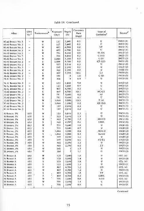
Table 19. Continued.
Corrosion
AlloyCDANo.a
EnvironmentExposure
(day)
Depth
(ft)Rate
(mpy)
Type of
Corrosion*7Source
Ni-Al Bronze No. 2 _ W 123 5,640 0.5 U INCO (3)
Ni-Al Bronze No. 2 - S 123 5,640 0.3 u INCO (3)
Ni-Al Bronze No. 2 - W 403 6,780 0.2 I-p INCO (3)
Ni-Al Bronze No. 2 - S 403 6,780 0.1 u INCO (3)
Ni-Al Bronze No. 2 - w 751 5,640 0.5 SL-DA INCO (3)
Ni-Al Bronze No. 2 - S 751 5,640 0.2 C(13) INCO (3)
Ni-Al Bronze No. 2 - w 1,064 5,300 0.2 C(5) INCO (3)
Ni-Al Bronze No. 2 - s 1,064 5,300 0.5 CR(21) INCO (3)
Ni-Al Bronze No. 2 - w 197 2,340 0.3 U INCO (3)
Ni-Al Bronze No. 2 - s 197 2,340 0.1 U INCO (3)
Ni-Al Bronze No. 2 - w 402 2,370 0.2 U INCO (3)
Ni-Al Bronze No. 2 - s 402 2,370 <0.1 ET INCO (3)
Ni-Al Bronze No. 2 - w 181 5 1.0 C(8) INCO (3)
Ni-Al Bronze No. 2 - w 366 5 0.4 U INCO (3)
Ni-Al Bronze No. 3- w 123 5,640 0.4 U INCO (3)
Ni-Al Bronze No. 3 - s 123 5,640 0.3 U INCO (3)
Ni-Al Bronze No. 3 - w 403 6,780 0.2 u INCO (3)
Ni-Al Bronze No. 3 - s 403 6,780 <0.1 NU-ET INCO (3)
Ni-Al Bronze No. 3- w 751 5,640 0.2 I-P INCO (3)
Ni-Al Bronze No. 3- s 751 5,640 0.1 U INCO (3)
Ni-Al Bronze No. 3 - w 1,064 5,300 <0.1 P(4) INCO (3)
Ni-Al Bronze No. 3 - s 1,064 5,300 0.2 CR(10) INCO (3)
Ni-Al Bronze No. 3 - w 197 2,340 0.3 U INCO (3)
Ni-Al Bronze No. 3 " s 197 2,340 0.2 U INCO (3)
Si Bronze, 3% 65 3 w 123 5,640 1.3 U INCO (3)
Si Bronze, 3% 653 s 123 5,640 1.5 U INCO (3)
Si Bronze, 3% 65 3 w 403 6,780 1.2 MO-CO INCO (3)
Si Bronze, 3% 65 3 s 403 6,780 0.4 GBSL INCO (3)
Si Bronze, 3% 653 w 751 5,640 1.0 U INCO (3)
Si Bronze, 3% 653 s 751 5,640 0.7 U INCO (3)
Si Bronze, 3% 65 3 w 1,064 5,300 0.6 MO-CO INCO (3)
Si Bronze, 3% 65 3 s 1,064 5,300 0.4 SL-CO INCO (3)
Si Bronze, 3% 653 w 197 2,340 1.1 u INCO (3)
Si Bronze, 3% 653 s 197 2,340 0.1 NU-ET INCO (3)
Si Bronze, 3% 653 w 402 2,370 1.2 U INCO (3)
Si Bronze, 3% 653 s 402 2,370 0.2 ET INCO (3)
Si Bronze, 3% 653 w 181 5 1.7 U INCO (3)
Si Bronze, 3% 653 w 366 5 1.1 G INCO (3)
Si Bronze A 655 w 123 5,640 1.6 U CEL (4)
Si Bronze A 655 w 123 5,640 1.4 U INCO (3)
Si Bronze A 655 s 123 5,640 1.8 u CEL (4)
Si Bronze A 655 s 123 5,640 1.5 u INCO (3)
Si Bronze A 655 w 403 6,780 1.2 CO CEL (4)
Si Bronze A 655 w 403 6,780 1.2 u INCO (3)
Si Bronze A 655 s 403 6,780 1.8 ET CEL (4)
Si Bronze A 655 s 403 6,780 0.2 GBSL INCO (3)
Si Bronze A 655 w 751 5,640 0.8 S-CO CEL (4)
Si Bronze A 655 w 751 5,640 1.4 U INCO (3)
Si Bronze A 655 s 751 5,640 0.9 G INCO (3)
75
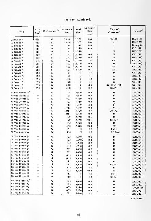
Table 19. Continued.
Corrosion
AlloyCDANo.a
EnvironmentExposure
(day)
Depth
(ft)Rate
(mpy)
Type of
Corrosion*7Source
Si Bronze A 655 W 1,064 5,300 0.6 SL-CO INCO (3)
Si Bronze A 655 S 1,064 5,300 0.4 U INCO (3)
Si Bronze A 655 w 197 2,340 0.8 U Boeing (6)
Si Bronze A 655 w 197 2,340 0.9 U CEL (4)
Si Bronze A 655 w 197 2,340 1.1 U INCO (3)
Si Bronze A 655 S 197 2,340 0.6 U CEL (4)
Si Bronze A 655 S 197 2,340 0.2 U INCO (3)
Si Bronze A 655 w 402 2,370 1.0 ET CEL (4)
Si Bronze A 655 w 402 2,370 0.8 U INCO (3)
Si Bronze A 655 S 402 2,370 0.8 ET CEL (4)
Si Bronze A 655 s 402 2,370 0.1 ET INCO (3)
Si Bronze A 655 w 181 5 1.8 U CEL (4)
Si Bronze A 655 w 181 5 1.6 G INCO (3)
Si Bronze A 655 w 366 5 1.2 G INCO (3)
Si Bronze A 655 w 398 5 1.1 G CEL (4)
Si Bronze A 655 w 540 5 2.5 CR(30);C(15) CEL (4)
Si Bronze A 655 w 588 5 0.9 CR(9) CEL (4)
Ni-Vee Bronze A - w 123 5,640 0.7 U INCO (3)
Ni-Vee Bronze A - s 123 5,640 0.5 U INCO (3)
Ni-Vee Bronze A - w 403 6,780 0.6 U INCO (3)
Ni-Vee Bronze A - s 403 6,780 0.3 U INCO (3)
Ni-Vee Bronze A - w 751 5,640 2.6 s! INCO (3)
Ni-Vee Bronze A - s 751 5,640 0.4 u INCO (3)
Ni-Vee Bronze A - w 1,064 5,300 2.2 CR (20) INCO (3)
Ni-Vee Bronze A - s 1,064 5,300 0.3 u INCO (3)
Ni-Vee Bronze A - w 197 2,340 0.6 u INCO (3)
Ni-Vee Bronze A - s 197 2,340 <0.1 NU-ET INCO (3)
Ni-Vee Bronze A - w 402 2,370 0.4 U INCO (3)
Ni-Vee Bronze A - s 402 2,370 <0.1 ET INCO (3)
Ni-Vee Bronze A - w 181 5 2.0 P(7) INCO (3)
Ni-Vee Bronze A - w 366 5 1.5 CR(10) INCO (3)
Ni-Vee Bronze B - w 123 5,640 0.6 U INCO (3)
Ni-Vee Bronze B - s 123 5,640 0.4 U INCO (3)
Ni-Vee Bronze B - w 403 6,780 0.5 U INCO (3)
Ni-Vee Bronze B - s 403 6,780 0.1 U INCO (3)
Ni-Vee Bronze B - w 751 5,640 0.5 U INCO (3)
Ni-Vee Bronze B - s 751 5,640 0.3 U INCO (3)
Ni-Vee Bronze B - w 1,064 5,300 0.3 U INCO (3)Ni-Vee Bronze B - s 1,064 5,300 0.4 U INCO (3)Ni-Vee Bronze B - w 197 2,340 0.6 u INCO (3)Ni-Vee Bronze B - s 197 2,340 <0.1 NU-ET INCO (3)Ni-Vee Bronze B - w 402 2,370 1.2 U INCO (3)Ni-Vee Bronze B - s 402 2,370 <0.1 ET INCO (3)Ni-Vee Bronze B - w 181 5 1.8 P(4) INCO (3)Ni-Vee Bronze B - w 366 5 1.3 CR(6) INCO (3)
Ni-Vee Bronze Ce - w 123 5,640 0.8 U INCO (3)
Ni-Vee Bronze C - s 123 5,640 0.5 U INCO (3)Ni-Vee Bronze C - w 403 6,780 0.8 U INCO (3)Ni-Vee Bronze C - s 403 6,780 0.2 U INCO (3)Ni-Vee Bronze C - w 751 5,640 2.0 G INCO (3)
76
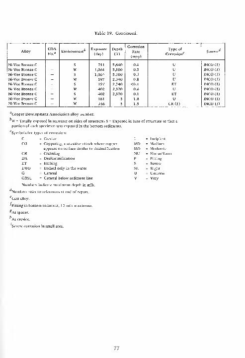
Table 19. Continued.
AlloyCDANo.a
f bEnvironmentExposure
(day)
Depth
(ft)
Corrosion
Rate
(mpy)
Type of
Corrosion 17Source
Ni-Vee Bronze CNi-Vee Bronze CNi-Vee Bronze CNi-Vee Bronze CNi-Vee Bronze CNi-Vee Bronze CNi-Vee Bronze CNi-Vee Bronze CNi-Vee Bronze C
-
S
WS
WS
WS
WW
751
1,064
1,064
197
197
402
402
181
366
5,640
5,300
5,300
2,340
2,340
2,370
2,370
5
5
0.4
0.5
0.3
0.8
<0.1
0.6
0.1
1.8
1.5
UUUUETUETU
CR(5)
INCO (3)
INCO (3)
INCO (3)
INCO (3)
INCO (3)
INCO (3)
INCO (3)
INCO (3)
INCO (3)
Copper Development Association alloy number.
W = Totally exposed in seawater on sides of structure, S = Exposed in base of structure so that ;
portion of each specimen was exposed in the bottom sediments.
Symbols for types of corrosion:
C = Crevice
CO = Coppering, a selective attack where copper
appears on surface similar to dezincification
CR = Cratering
DA = Dealuminification
ET = Etching
EWO = Etched only in the water
G = General
GBSL = General below sediment line
Numbers indicate maximum depth in mils.
Numbers refer to references at end of report.
Cast alloy.
/,
I = Incipient
MD = MediumMO = Moderate
NU = Nonuniform
P = Pitting
S = Severe
SL = Slight
U = Uniform
V = Very
Pitting in bottom sediment, 12 mils maximum.
*At spacer.
At crevice.
Severe corrosion in small area.
77

Table 20. Stress Corrosion of Copper Alloys (Bronzes)
AlloyCDANo."
Stress
(ksi)
Tensile
Strength
(%)
Exposure
(day)
Depth
(ft)
Specimensc bSource
Exposed Failed
Phosphor bronze A 510 12.0 50 403 6,780 2 CEL (4)
Phosphor bronze A 510 19.0 75 403 6,780 2 CEL (4)
Phosphor bronze A 510 12.5 50 197 2,340 3 CEL (4)
Phosphor bronze A 510 18.7 75 197 2,340 3 CEL (4)
Phosphor bronze A 510 12.6 50 402 2,370 3 CEL (4)
Phosphor bronze A 510 19.0 75 402 2,370 3 CEL (4)
Phosphor bronze D 5 24 10.0 35 403 6,780 2 CEL (4)
Phosphor bronze D 524 14.0 50 403 6,780 2 CEL (4)
Phosphor bronze D 5 24 21.0 75 403 6,780 2 CEL (4)
Phosphor bronze D 524 9.8 35 197 2,340 3 CEL (4)
Phosphor bronze D 524 13.9 50 197 2,340 3 CEL (4)
Phosphor bronze D 524 20.9 75 197 2,340 3 CEL (4)
Phosphor bronze D 524 16.4 50 402 2,370 3 CEL (4)
Phosphor bronze D 524 24.5 75 402 2,370 3 CEL (4)
Al bronze, 5% 606 18.0 35 403 6,780 2 CEL (4)
Al bronze, 5% 606 26.0 50 403 6,780 2 CEL (4)
Al bronze, 5% 606 38.0 75 403 6,780 2 CEL (4)
Al bronze, 5% 606 17.9 35 197 2,340 3 CEL (4)
Al bronze, 5% 606 25.6 50 197 2,340 3 CEL (4)
Al bronze, 5% 606 38.4 75 197 2,340 3 CEL (4)
Al bronze, 5% 606 28.3 50 402 2,370 3 CEL (4)
Al bronze, 5% 606 42.5 75 402 2,370 3 CEL (4)
Si bronze A 655 10.0 35 403 6,780 2 CEL (4)
Si bronze A 655 14.0 50 403 6,780 2 CEL (4)
Si bronze A 655 21.0 75 403 6,780 2 CEL (4)
Si bronze A 655 9.6 35 197 2,340 3 CEL (4)
Si bronze A 655 13.8 50 197 2,340 3 CEL (4)
Si bronze A 655 20.6 75 197 2,340 3 CEL (4)
Si bronze A 655 10.8 50 402 2,370 3 CEL (4)
Si bronze A 655 16.2 75 402 2,370 3 CEL (4)
"Copper Development Association alloy number.
Numbers refer to references at end of report.
78

ssrh -i- -T * -t- ^h <* -i- -t Th * "* •* *t- -t- -t -h -1- Tj- -i- -t- -+ Tj- * *
3 J j J _! - nJ J J J J J J J J J j J J J nJ J J J J Jo td cd w H cd w w w w W w (d w w w ^v W td w Id w (d td td LdCO u u u U u O u u o u o u o O u U u U o U u U U O U
0£l
c m ts t-H T-H m C*3 o m T-H m r-i * ON o\ t^ r~ fs] o rs) T-H o T-H rn C-. rnX + + 1 1 1 1 + 1 + 1 + 1 <N cs I (N 1 1 -i- 1 1 1 +
B U 1 I 1 1 1
a]^
C_o
3 .5 ^[5i £?
"* ^h ^h Tl- -1- * o © o O o ovo vo vO VO vO vO t-- r~ i-- t-~ f- f~. ^h -+ -d- ^h * •* VO VO VO \o VO VO VO
O~
VOil
cx m T-H T-H m rn r^ o T-H m ro T-l r-H cs O ,-H r^ O m * + 00 in * m r^1 1 1 1 + + 1 + + + + 1 1 + 1 1 1 1
60C U 1 1 1
V ^CO
[u ~rt
£ ;§>!*oo oo oo 00 00 oo 00 oo 00 oo oo oo oo
fS ts r-i CM (N (N PJ M (N <s IN <N (N
o
ajbxj
cX o H T-H m rH O T-H <s <N O T-l T-H o T-H o O o rn CN T-H in T-H rs) T-H T-H
M X + + 1 1 + + + + 1 1 1 + 1 1 1 1
C u 1
^to
'wS "rtc c .o
"gi J5^f- <*- •* + * Th 'i- * d- -tf-
•* Th -d-H vo \o O VO ^o vO oo 00 00 00 00 00 o ^o \o ^o -o vO vo
o
•«
o o o O o o o 3 o o O o o O o o o 3 3 O O ma. ,<-• <* oo -t- -I" r^ * oo -1- -+ r-- -* oo -+ •+ r- -1- X 00 -t- * r~
Qvo vo m m vo t~~ O m fv-l O t^ VO m \o r^ r~. ^C m m"> vO in (N c-1 "- \o 10 <N tN in >o ir, <M (N IT, o ^o ^ CN <N
|^r~. t~- (N t-. IN m t^ (M rt
O c* rv] Ov 3 oo (N o O O oo tM 3 ON 3 00 (S 3 o a- O 00a. -c ^ r~ ^h -1- t-~ -f -+ t~~ -t -+ -+ r~ <*• rHX '-'
w
< «. _ o ^^ _^ 3 o * rh •* * d- * vO VO ^O ^O ^O vO ^ « OT m «Q o rvl IN 3 C 3 c O OU Z in in in in U1 in U1 in in m m ID \o VO VO \o ^O o VO VO ^o \o vo vo vo
< < < < < < Q Q Q Q Q Q4J V U V u u V u uN N N N N N N N N NC c c c c c c c B c c cO o o o o o o o O o o
o .5 _o XIIn
Xl x XI XI £ £ X) X! XIin m m in in m < < < < < < <
3,
u u V OJ HI oj aj uo o o o o a o o o o N N N N N NX x x jr. J3 c C B c — c c c c C3 c c
"a. 7" a. E_ a.
oa.
O o oa,
o
oX
oX XI X
oX XI
oXl
oX
oX
oX
OX
OX X
X jC J3EL Hu cu — a, a. a. a. CU a. Ou 0h < < <; < <J "" C/5 C/5 C/5 CO oo CO CO
79
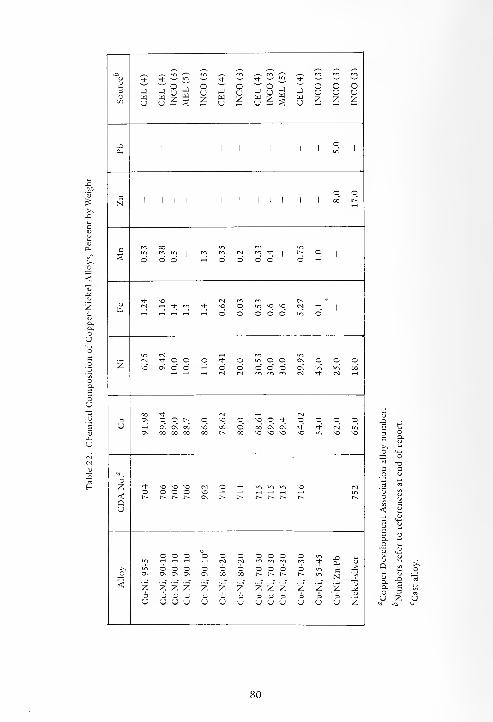
mu + -1-
n o J. o-t-
o<*
o o o3 J 1-1 u (
)
1-1 u 1-1; ) hJ (
)
u uC/3 u
UJu z z w
u z V. u z z z
J3 oPn
o oCN 1 1 1 1 1 1 1 1 1 1 1 1 oo r^
c ro CO
|
inCnI
« *1
1-^ oI 1
o o o o o o o o
^)- NO rsi r-(N 1-t * rr> * NO o in NO NO (N *—
1
1 1
o o o o o o
rNi
z(N *- o O o •>* o in o o On o o oNO On o o ^H o o o n -
On m in 00(S (N (N * Cn)
CO * c~i rq3 On O o r^ o NO o NO o * O O o ou r-H On On oo NO 00 o oo On On * * (N in
On 00 CO 00 oo 00 NO NO no NO NO NO
z * NO NO NO O NO
<O O O o NO
1 I
r~- r-. 1^ r^ On t^ t-^ f^ r^ r~- t~^ r-QU
o o o O o o o c o or-1 M m •* V
>^ m - o o O O o o o o o inOn On o On On CO 00 t-~ t-^ t^ r-- in N ?
< Z z Z z z Z z z Z Z Z z Z3 3 3 3 3 3 3 3 3 3 3 3 3 .\i
u u U u u u u u U u u u u Z
80

T3
3OC/2 uouuououuu
,"ro"ro^o^Oj~-:oo_|0INC0(3
CEL
(4)
INCO
(3
CEL
(4)
INCO
(3
O OI) "Sa. p>* tH o
DDDD3D33D3 SDDDDDDDDD^^DSD U D D D D
Corrosion Rate
(mpy)
in«lM!DNiOOi>00\00 o\\oootsoooo^or^<-iu-ir~-\oir>'Ot^ CM 00 CO U-| t-h^^©OOOOOOO 0-h©>-<00000000000V
O o o o oV
oooooooooo'J-'+OOOOri-Tj-Tj-Tl-t-t^
ooooooooooooooo+ *^* + eocoaoo**i-'too o o o o oo * "d- * *ininvovommcMfvINN i/->uimui»r>\0'ONONOmu">i/-ji/-iU">ij"i m N N N N
ISD. "U
rri rri m m i—I i-< t^ t^ C\1 <NfNC\100u">"">ONO\00 CNC*)CNCslcvlOOOOt/%ir>u"iw>\o vOtJ- Is- t- t- r~no ON on o\ On0_ rt rt ,-H <-H
-51
C
1co'>c[I]
^to^coj^co^izi^to ^^^COCO^^C/}!*)^^^;/}^^ to ^ ^ to co
< =.Q oU Z
OOOOOOOOOO OOOOOOOOOOOOOOO *o ^o ^o *o ^oo o o o ot^- t^ i— r-~ c~~
<OOOOOOOOOOOOOOO o o o o o
ONONONONONONONONONON 666666666666666ONONONONONONONONONONONONONONON 6 6 6 6 6ON ON G\ On On
ZZZZZZZZZZ3333333333uouuuuuuuuzzzzzzzzzzzzzzz333333333333333CJUUUUUUUUUUUUUU
z z z z z3 3 3 3 3u u u u u

^8^jW 7 W Sillso o o ou o o uz z z z
° ^ °u H uz H z
J uHuz « zk — s; u — usu — uSu — St! £
;
o o o ou u u uz z z z
°< 2>* cH ou
b 3 b 3 D D D D 3 D 3 5 5 P3DD33D5
»H rH on \q
d h 6 6^h r-i On N^^'-'NinOHMWOO i-H © rHr-HrHiHr-ii-HT-H©'©r-lT-H
t^. -( in
d i-h 6
ooooooooooooooooM N N N
oo oo oo oo
in in in in \d ^O \d no in (v) (N (N
Tj- Tj" ^- ^N N H voO O 00 o** & ^h m © © © o inminNONOONONON
t^-t^.r^oO'-i'-i'-i
^St/NCrt^^^^^ ^C«^^ ^^c/nc/J^^OOC/nJS^I/n^C/n^^c/n
< «.Q oU Z
nOnOnononononononoooooooooorvtv.t-~i-vt^t^tv.f^r~
(M (S <sl tsl
VO no ^O NOON On OS On
0>-lO>-lO-HO>-lOT-lrH^HT-<0'-<0r^t^r^tv,t^t^t^r^t^t^t^tv-t^t^t^r^
V*~, ho bo bo b<)OOOOOOOOO oooo ooooooooooooooooi-li-(i-li-ir-(i-l»-li-l.-l i-H .-! iH i-H CnJCJ(S(S(N(S(S(S(S(V1(S1(S(VJ(S1(V|(V1ooooooooo oooo ooooooooooooooooOnOnOnOnOnOnOnOnOn OnOnOnOn oooooooooooooooooooooooooooooooo
zzzzzzzzz zzzz333333333 3 3 3 3UUUUUUUUO UUUUzzzzzzzzzzzzzzzz3333333333333333uuuuuouuuouuuuou
82

u
3O
INCO
(3)
CEL
(4)
INCO
(3)
CEL
(4)
INCO
(3)
INCO
(3)
INCO
(3)
MEL
(5)
CEL
(4)
INCO
(3)
CEL
(4)
INCO
(3)
CEL
(4)
INCO
(3)
CEL
(4)
INCO
(3)
MEL
(5)
CEL
(4)
INCO
(3)
INCO
(3)
MEL
(5)
ouz
cuz CEL
(4)
CEL
(4)
INCO
(3)
CEL
(4)
INCO
(3)
^8S5
o o
Q. O
H oU
v o o d 5 a aC/3
D D D D DDDDU^DOD^ 3 o £ D 3 D "
CO
D D
Corrosion Rate
(mpy)
.-, no .-i in <N 00 On © CS m 00 0^rntSi-iNTj-r~-0\t-»u"> NO NO ?n On M H in no
O O <-i O O rg i-i
V^ ^H ^ © Oi-i^H^OOOOOO o © O © © © ©
V© O
a
O O O O O m mrj- r-~ t-~ t-~ t-~
N N N N N
o o o o* it + *>o >o iO iO
0©0©©©©0©0"tososeoco't + 't + ono t*~ *r^ n f> \o *o o io w
oo oomO O O O OO * ^- Tj- rj-
o ©
ia m m ift lnN©NONONOmminlnln Irt m N tN} N fN) M n N
O rt
a. -ax ^
t-~ fM (S N ?S i-H n©On O O O O 00 \o
cr> m m m(S M c*J eg
mmmmm^H,—I,—,,—,^-NOOOOiAiAininNO NOo
NOm r~ r- t~ t-~
rM 0\ On On OnrNi N© ©
cuBao
>cw
tfl J J !/) M ^ ^ ^ L* ^ t« oo^^coon^^^oo^ £ lo ^ ^ ^ in ai £ £
< «.Q ou z
i-l O H O i-H —i iH in in in m mmminininmininm 1ft m m in ia ia m in U~i
t-~ r-- t-~ r~ r^ i-. t~- t~- t^ r^ r^ r^t^t-~r^r-~r^r^t^r^i>- r^ r^ r^ t~ r~ r^ r^ t-- t-~
<o o o o o o oN N N N N M N6 6 6 6 6 6 6oo oo oo oo oo oo oo
u oj aj <u
tL, tL, tL, tL,
IA Ift IA IA
u V V <U V VLL, tL, tL, tL, tL.
IA 1A IA IA IA
tL, LL,
in in
o o o o ooooooooo© © O © © © © © © ©o o © o6 6 6 6t>. r» f> t~-
©ooooooooo6666666666
©m6
©6
o o © © ©6 6 6 6 6r-- r-~ r-. t^ r^
© ©6 6
z z z z z z z3 3 3 3 3 3 3u u u u u u o
z z z z3 3 3 3o u u o
zzzzzzzzzz3333333333ouuuuuououZ3u
z3u
z z z z z3 3 3 3 3u u u u u
Z Z3 3u u
83

^3uU <*- — rj- — -- ;£•** "+*»* -I- <* -+ «t Tj- rj- rh rh *J- >*
ususeSuu—' ^^ —
'
—
'
'
—
w — W '—
'
** ^* w '' n 00000
o - - - N-l _J J -J -J -J -1 >J J Jt
)
u u u u u uco UblU w uj LU LU W UJ UJ UJ HI UJ z z z z z z z zu u u U u u u u u U u u u
O ou u ^^ w
COSO * DrH rs|
o o ^ ^"'il i ^*. Pi H
Q. O
H o
D 3 £CM
pzPz3 3 3 P u
CL,"
b!
u D 3 D " D DCO (X
Uso ? u uu u
o -~.
rrosi Rate
mpy
i-rtinin^N + m fs) fs) rH ,-H m ts ,-, rH rH rH 00 t> >o c~ t^ ts >-h m O mOOOOOOOO o o o o o o o O O O ^ O rH O rH Oo — Vu
o o o o o o o O in in in OOOOO O O* <* 00 00 <* -1- ^h * t^ t~« ^i- •* 00 00 * * O Oqj <+-<
so so t-~ r^ so so m m m rrj sO \o t-^ r^ so so m m<s <s in m so so in in fS Psl <S (N in in so so in in in in
um m m f~ i~- csi CM 00 00 m m rr» rH rH Th t*-
OOOOOOsOOOOs© N N O o in Os on O 00 Os O !N rsl O O in in SO soO rt rJ--r)-rHrHmrnmso rH rH ^J- <* r~- r~ rH * * (w-i \n rH •*) x^ t^- t^ O OD- T3
w
-o
cuEco
coco^^^^^^ ^ CO ^ oo £ CO £ 00 ^ CO £ ^ ^ £ CO ^ CO ^ CO ^ CO
>cu
< «.Q oU Z
irtinifiinviviifiiA so so so SO so so -O so so SO MD -0
r^c--t^t--r^t^r~-r^ r^ r-~ t^ t^ r^ t^ r^ t~- t-^ r-~ t^ t^ t~
<<-,OJU3J5JQJWWU U ubbhbbbhh U_ IX, u. U, H. Ph U, U. Cx, U, Ix, u. u-
i/iirimiAiniAiAift o o o O o O O O O O O>, OOOOOOOO m m in LT. in IT. m in in in in in m
OOOOOOOO o o o o o o O O O O O O O in in in in in in in in< rrjmmrrimmmrri CT) m en m <* rj- Tl- Tj- Tj- Tf t tOOOOOOOO o o o o o o O O O O O O in in in in in in m in
r^r~r~r~f^t~r~r^ t^ f^ t^ t^ l-^ l-^ t^ t-« t-- t^ t- f- t^. in in in in in in in in
ZZZZZ2Z2 Z Z Z z z z Z z z z Z z z z z z z z z z z33333333 3 3 3 3 3 3 3 3 3 3 3 3 3 3 3 3 3 3 3 3 3uoouuuuu u u u u u u u <J U u u u u u u u u
84

T3
3OCO
m m m m m rr> m m m rr, m rr> m m cr> m cri m m m ro m w% m rr> ro m m mo o o o o ou u u u u uz z z z z z
o o o o o o oU U U O U <J oz z z z z z z
o o o o o o oCJ u u u u u uz z z z z z z
o o o o o o ou u u o u u uz z z z z z z
O Ou uz z
o
a. o£• tH oU
a,
3 "*- D [2 ^ ^ D D D a D D ^ D D " 3 [2 S Don
3 3 p £ D 5 5 O 5
Corrosion Rate
(mpy)
oo cn r- ih oo cn On no oo <-h no m in m in rH Th rH o f- O ^O + in m M >o •d- oO O O O .-i rH o o o o o o o O O O O O rH o
V Vcn cn rH o rH o O O T-l
S. 'P*> SiQ
O O O O m m^ rt" r~ t»m w r«i mCN CN cn CN
o © o o o o o+ * oo oo * + ono no ("^ r^ no no m
O O O O O m inO »t •*• t- t^
o o o © o o o* + » 00 + + oNO NO r-~ t^ NO no rn
o oo **•
ia m \o ^O m ia ift m N N N N in in no so in in in in cn
I?w
tN N N N rH >0on o\ © o oo noi-i t-h Th ^- i-h r«
m ro m r*"> t—I i—i rj-
(N CN © O m in NOh h + * h n q<* t- l-~ CN CN r-i noNO On On O O CO noO rt h i- + h m
m rri m m r-I rH tJ-
cn cn o O m in no*-> <-( <* «*• r^ r- ©^
NO On
-a
C<u
Eco'>
Ew
S» CO ;» CO ;> ^ ji» CO ^ co ^ co ^ CO ^ CO ^ CO ^ ^ ^ CO ^ CO ^ CO ^ CO ^
Q oU Z
1 1 1 1 1 1 1 1 1 1 1 1 1 1 1 1 1 1 1 1
IS N (N N N N Nt-- t-~ t-^ t-- t-- f~ t^
CN CNin in
<
,
55-45
,
55-45
,
55-45
,
55-45
,
55-45
,
55-45
ii jd j j: ^ j j3Cu CU Cu C1h cu cu cu
E E G G C G GN N N N N N N
^ xi j: xi j: j3 xi0- CU & CU CU CL| Cu
c g c g c g cN N N N N N N
j '-> "-> j *~> o j>>>>>>> CJ CJ> >
CO CO CO CO CO CO CO
_J "J CJ u u ^^ -M Jj ^s ^ ^ _*CJ U CJ CJ u u u
Z Z Z Z Z Z Z
cp CO
~& ~u^ ^£CJ CJ
z z
Z Z Z Z Z Z3 3 3 3 3 3<J o u u u u
z z z z z z z3 3 3 3 3 3 3u u u u u u u
Z Z Z Z Z Z Z3 3 3 3 3 3 3U U U U <J U U
85

uu3
INCO
(3)
INCO
(3)
INCO
(3)
INCO
(3)
INCO
(3)
O O
°> 2>> t:
H oU
HW •-, H ;-, •-,
j » w => 3
Corrosion Rate
(mpy)
<0.11.0 0.1 1.1 0.7
a. 3Q ~
O O O u-> >n* t^ r-
N N N
1 *O rt
a. -ax -^w
h N N H SOOs © O 00 \orH + * H m
c<u
Eco'>
cw
C/3 ^ in ^ ^
Q oU Z
N N N « Nia in in in mt-~ t» t- r- t--
<
Nickel-Silver Nickel-Silver Nickel-Silver Nickel-Silver Nickel-Silver
XI uE
03 Dc U .- Z
-a
aj «i
R&<
R
M O
OiZSon^SoD
0- PU C/3 C/5 D
s3R
3 R
u us y„ .c j3
u w u w U -oc
ii n ii ii ii
ou u
Oh h P3u w u w d
« c/
y u £ Z § ,W U z
86
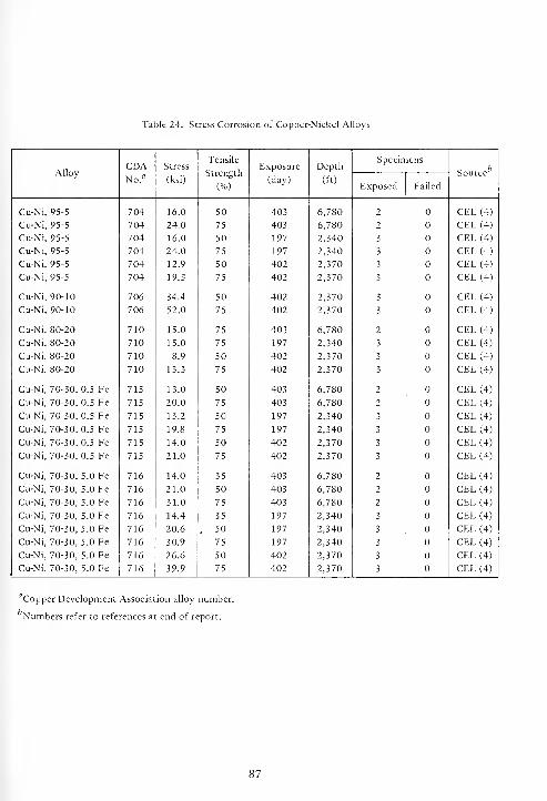
Table 24. Stress Corrosion of Copper-Nickel Alloys
AlloyCDANo. fl
Stress
(ksi)
Tensile
Strength
(%)
Exposure
(day)
Depth
(ft)
Specimensc bSource
Exposed Failed
Cu-Ni, 95-5 704 16.0 50 403 6,780 2 CEL (4)
Cu-Ni, 95-5 704 24.0 75 403 6,780 2 CEL (4)
Cu-Ni, 95-5 704 16.0 50 197 2,340 3 CEL (4)
Cu-Ni, 95-5 704 24.0 75 197 2,340 3 CEL (4)
Cu-Ni, 95-5 704 12.9 50 402 2,370 3 CEL (4)
Cu-Ni, 95-5 704 19.3 75 402 2,370 3 CEL (4)
Cu-Ni, 90-10 706 34.4 50 402 2,370 3 CEL (4)
Cu-Ni, 90-10 706 52.0 75 402 2,370 3 CEL (4)
Cu-Ni, 80-20 710 15.0 75 403 6,780 2 CEL (4)
Cu-Ni, 80-20 710 15.0 75 197 2,340 3 CEL (4)
Cu-Ni, 80-20 710 8.9 50 402 2,370 3 CEL (4)
Cu-Ni, 80-20 710 13.3 75 402 2,370 3 CEL (4)
Cu-Ni, 70-30, 0.5 Fe 715 13.0 50 403 6,780 2 CEL (4)
Cu-Ni, 70-30, 0.5 Fe 715 20.0 75 403 6,780 2 CEL (4)
Cu-Ni, 70-30, 0.5 Fe 715 13.2 50 197 2,340 3 CEL (4)
Cu-Ni, 70-30, 0.5 Fe 715 19.8 75 197 2,340 3 CEL (4)
Cu-Ni, 70-30, 0.5 Fe 715 14.0 50 402 2,370 3 CEL (4)
Cu-Ni, 70-30, 0.5 Fe 715 21.0 75 402 2,370 3 CEL (4)
Cu-Ni, 70-30, 5.0 Fe 716 14.0 35 403 6,780 2 CEL (4)
Cu-Ni, 70-30, 5.0 Fe 716 21.0 50 403 6,780 2 CEL (4)
Cu-Ni, 70-30, 5.0 Fe 716 31.0 75 403 6,780 2 CEL (4)
Cu-Ni, 70-30, 5.0 Fe 716 14.4 35 197 2,340 3 CEL (4)
Cu-Ni, 70-30, 5.0 Fe 716 20.6 . 50 197 2,340 3 CEL (4)
Cu-Ni, 70-30, 5.0 Fe 716 30.9 75 197 2,340 3 CEL (4)
Cu-Ni, 70-30, 5.0 Fe 716 26.6 50 402 2,370 3 CEL (4)
Cu-Ni, 70-30, 5.0 Fe 716 39.9 75 402 2,370 3 CEL (4)
'Copper Development Association alloy number.
'Numbers refer to references at end of report.
87

3
tn
+ •*•+*+ * * <*• * + * rf -t Tj- n+ tJ- **** * <* •+ * -t + •+ *_J _1 _) _1 Jw a w tu uj
U <J u u oJ J J _) -J _U Id U U Id bl
u o u u u uJ _ J _] J_ _ _ _ _u nJ u u <j
j j j j J j______V O U U CJ u
j J J J J J______u u u u u u
c.2
BO
_0
5
c
U
CNt in <N r^ ^-+ 1 + + +
o in ol ts no CO (S ro ro w (S+ 1 1 + 1
m en tJ- rt m m+ 1 1 + 1 -1
1
i-h i-i ON O 00 w+11 1 iH
O" ----- +*+*+•* * ^ * * * <J- ++*+ *
----
a
CO
c
-CU
NQ m m ON NO i-h no ON O m GNw + + i-i ++ +
ffl N « NO N1 1 1 1 1
n h -t -j- rn onIII-—III1
in m m + O no+ 1 + 1^-1 +
'Si J?
ow
M N « (S [N no no no NO no no M N « N N NO NO NO NO NO NON N M rj N M ^- * Th •+ T+ +
u^H <N T-i ^t- ^H+ + 1 1 1
m m m h -* -*+ + + 1 + +
O CnI i-h iH i-h
+ + + + + C\l <N 1 + +N rl ffl H Mfi+ I + + + +
S>JS
6~
CO CO CO CO 00•* * •* •* rh "tf-
ON ON ON ON ON* * * Tt" * CO 00 00 CO 00 GO 00 CO 00 00 CO COt^ r^ r^ t^ t^ t^
_ 2SJ-
o o o o oTt- 00 ^ *+ [^v© t^ <0 m m
O O O O O mrt CO ^J- "^- l^no t^ no m m
o o o o o* M tJ- -+ r^>0 N n! m m
O O O O O in* « * + sno r^ no m m
O O O O O in* CO If * f-NO t^ no n-i m
Ift >0 IA N N m no in M Csl in * »i N N m no in el (S in no in ts (N
1 >,
a. "0
m m ^ n NN o m ON oi-i * ^ ih rf
m m i-H t^ (N wIN O in ON O CO^H -+ t^ -< -f _l
rn rn i-h r^ cn]
fNl O u-i ON Oh it (n H *m m i-h r^ fN ^hn O m on O 00-i •* t-» <h * -I
m rr, i-i r^ Cn) ^H(N o m on O 00rt Tj" t^ i-l N+ t-H
a oJ z
o o o o or^ r^ [^ t^ l^
NO NO NO \0 NO NOo o o o o or-- t—
^t-^ r^ t— c--
O O O O O m in in m in in NO NO NO NO NO NO
r-> r^ r^ r* t^ r^ t^ r-* r-~ t*- r-- r^ t-^ r^ r^ t^ r^
IXo
<
Cu-Ni,
95-5
Cu-Ni,
95-5
Cu-Ni,
95-5
Cu-Ni,
95-5
Cu-Ni,
95-5
Cu-Ni,
90-10
Cu-Ni,
90-10
Cu-Ni,
90-10
Cu-Ni,
90-10
Cu-Ni,
90-10
Cu-Ni,
90-10
Cu-Ni,
80-20
Cu-Ni,
80-20
Cu-Ni,
80-20
Cu-Ni,
80-20
Cu-Ni,
80-20
_. ft. 6. ft. ft. Ch ______o o o o o o
o o o o o o in in in in in in
Cu-Ni,
70-30
Cu-Ni,
70-30
Cu-Ni,
70-30
Cu-Ni,
70-30
Cu-Ni,
70-30
Cu-Ni,
70-30
Cu-Ni,
70-30
Cu-Ni,
70-30
Cu-Ni,
70-30
Cu-Ni,
70-30
Cu-Ni,
70-30
Cu-Ni,
70-30
88
SECTION 4
NICKEL ALLOYS
Nickel and its alloys are passive in moving sea-
water, but are subject to pitting and concentration
cell (crevice) corrosion in stagnant seawater. Their
passivity is due to the presence of an impervious
oxide layer on their surfaces which breaks down
under certain conditions. Fouling organisms, deposits,
and crevices which restrict the availability of oxygen
to localized areas cause such breakdowns. Where
sufficient oxygen is not available to repair the breaks
in the protective film, pitting and crevice (concentra-
tion cell) corrosion occur. Thus, in seawater, pitting
and crevice corrosion are the most prevalent modes of
attack.
Corrosion rates calculated from weight losses due
to localized corrosion are meaningless because they
present an untrue picture of the corrosion behavior of
the alloy. Corrosion rates such as mils-per-year
connote a uniform thickness of metal lost over a
period of time, assuming uniform corrosion. Hence, a
very low corrosion rate resulting from a few deep pits
or crevice corrosion in one area will present a very
misleading picture of the corrosion behavior of an
alloy in that particular environment.
The data on the nickel alloys were obtained from
the reports given in References 3 through 19 and 23.
They are separated into different groups (nickels,
nickel-copper-alloys, and nickel alloys) for
comparison and discussion purposes.
The chemical compositions, corrosion rates and
types of corrosion, and changes in mechanical pro-
perties due to corrosion of the nickels are given in
Tables 26 to 28; those of the nickel-copper alloys in
Tables 29 to 31; those of the nickel alloys in Tables
32 to 34; and the resistance to stress corrosion in
Table 35.
The effects of depth and the effect of the concen-
tration of oxygen in seawater on the corrosion of the
nickels, the nickel-copper alloys, and the nickel alloys
are shown in Figures 15 and 16.
4.1. NICKELS
corrosion in Table 27, and the changes in their
mechanical properties due to corrosion in Table 28.
4.1.1. Duration of Exposure
The corrosion rates and types of corrosion of the
seven nickels (94% minimum nickel) are given in
Table 27. Pitting, crevice, and edge (on the sheared
ends) localized types of corrosion were responsible
for practically all the corrosion. The edge corrosion
was caused by microcracks and microcrevices that
formed during the shearing operation; this illustrates
dramatically the corrosion damage that can be caused
by this fabricating procedure. Lateral penetration,
initiated at a sheared edge, of as much as an inch
during 6 months of exposure was found. To prevent
this type of corrosion, all deformed metal created
during shearing or punching operations must be
removed by machining, grinding, or reaming.
Because the corrosion of the nickels was local-
ized, no definite correlation with duration of expo-
sure was possible. However, the severity of pitting
and crevice corrosion increased with increasing time
of exposure at depth as well as at the surface. Cor-
rosion rates increased with duration of exposure at
the 6,000-foot depth, although they were neither
progressive nor constant. In some cases corrosion
rates were considerably higher during shorter times of
exposure than after longer times of exposure. Cor-
rosion rates at the 2,500-foot depth were constant
with increasing time of exposure.
4.1.2. Effect of Depth
The severity and frequency of pitting and crevice
corrosion were much greater at the surface than at
depth. Also, the average corrosion rates were greater
at the surface than at depth, although they did not
decrease progressively with increasing depth as shown
in Figure 16. The curves in Figure 16 are based on
average values for each group of alloys.
The chemical compositions of the nickels are
given in Table 26, their corrosion rates and types of
89
4.1.3. Effect of Concentration of Oxygen
The severity and frequency of pitting and crevice
corrosion, in general, increased with increasing con-
centration of oxygen in seawater. The average cor-
rosion rates increased progressively, but not
constantly, with increasing concentration of oxygen
in seawater as shown in Figure 17.
4.1.4. Effect of Welding
The weld beads were preferentially corroded
when nickel Ni-200 was welded by manual shielded
metal-arc welding using welding electrode 141, and
by TIG welding using filler metal 61. The weld beads
were severely pitted when welded with electrode 141.
The weld beads and heat-affected zones were per-
forated when welded with filler metal 61. This
preferential attack of the weld bead materials
indicates that they were anodic to the parent sheet
metal.
4.1.5. Mechanical Properties
The effect of exposure on the mechanical pro-
perties of nickel Ni-200 is shown in Table 28. The
mechanical properties were not affected by exposure
at depth for 1,064 days or for 181 days at the sur-
face.
4.2. NICKEL-COPPER ALLOYS
The chemical compositions of the nickel-copper
alloys are given in Table 29, their corrosion rates and
types of corrosion in Table 30, and the changes in
their mechanical properties due to corrosion in Table
31.
4.2.1. Duration of Exposure
The corrosion rates and types of corrosion of
seven nickel-copper alloys are given in Table 30.
Except for the cast alloys 410 and 505, the pre-
dominant types of corrosion were pitting and crevice.
At the 6,000-foot depth there was an overall
tendency for the corrosion rates of the cast alloys to
decrease with increasing duration of exposure, but
this tendency was neither progressive nor constant.
Because the corrosion of the other nickel-copper
alloys was localized (pitting and crevice corrosion),
no definite correlation with duration of exposure was
possible either at depth or at the surface. However,
the intensity of pitting and crevice corrosion, in
general, increased with increasing duration of
exposure both at depth and at the surface.
4.2.2. Effect of Depth
The severity and frequency of pitting and crevice
corrosion were much greater at the surface than at
depth. Also, the average corrosion rates were greater
at the surface than at depth, although they did not
decrease progressively or constantly with increasing
depth, as shown in Figure 16. Although these
corrosion rates are unreliable because they are based
upon localized corrosion weight losses, they do sub-
stantiate the conclusion based upon the frequency
and severity of pitting and crevice corrosion.
4.2.3. Effect of Concentration of Oxygen
The severity and frequency of pitting and crevice
corrosion, in general, increased with increasing con-
centration of oxygen in seawater. Even though pitting
and crevice corrosion were the predominant types for
these alloys in seawater, their average corrosion rates
calculated from weight losses increased linearly with
increasing concentration of oxygen, as shown in
Figure 17.
4.2.4. Effect of Welding
When Ni-Cu 400 alloy was welded with filler
metal 60 by the TIG welding process, the weld beads
were severely pitted both in the seawater and in the
bottom sediment after exposure for 402 days at a
depth of 2,500 feet, but they were corroded uni-
formly after 181 days of exposure at the surface.
Butt welds in Ni-Cu 400 alloy made by the manual
shielded metal-arc process with electrode 190 were
attacked by incipient pitting corrosion both in the
seawater and in the bottom sediment after 189 days
of exposure at a depth of 5,900 feet and by crater
corrosion of the weld bead after 540 days of expo-
sure at the surface. Three-inch-diameter, unrelieved,
90

circular welds in Ni-Cu 400 alloy by the manual
shielded metal-arc process with electrode 190 cor-
roded uniformly both in the seawater and in the
bottom sediment after 189 days of exposure at a
depth of 5,900 feet. The unrelieved circular welds
were tested to determine whether welding stresses
would cause any corrosion-induced cracking. When
Ni-Cu 400 alloy was welded by the manual shielded
metal-arc process with electrodes 1 30 and 180, the
weld beads were corroded uniformly after 181 days
of exposure at the surface and after 402 days of
exposure at the 2,500-foot depth. There was no
preferential corrosion when Ni-Cu 400 was TIG
welded with electrode 167 after 402 days of exposure
at the 2,500-foot depth, but the weld bead was
selectively attacked and was covered with a deposit of
copper after 403 days of exposure at the 6,000-foot
depth [7j.
The weld beads in Ni-Cu K-500 alloy made by the
manual shielded metal-arc process with electrode 134
were attacked by pitting corrosion of the weld bead
and the heat-affected zone after 181 days of exposure
at the surface, by crater corrosion of the weld bead
after 540 days of exposure at the surface, and by line
corrosion at the edge of the weld bead after 402 days
of exposure at the 2,500-foot depth. When Ni-Cu
K-500 alloy was TIG welded with filler metal 64, the
weld beads were uniformly corroded after 181 days
of exposure at the surface and 402 days of exposure
at the 2,500-foot depth, and the weld beads and the
heat-affected zones were attacked by pitting cor-
rosion after 540 days of exposure at the surface.
4.2.5. Galvanic Corrosion
When AISI 4130 steel was fastened to Ni-Cu 400
alloy in a surface area ratio of 1:2, the AISI 4130 was
severely corroded and the Ni-Cu 400 was uncorroded
after 403 days of exposure at the 6,000-foot depth
[7] . This shows that the steel was being sacrificed to
protect the nickel- copper alloy.
4.2.6. Crevice Corrosion
4.2.7. Corrosion Products
X-ray diffraction, spectrochemical, and chemical
analyses of corrosion products removed from nickel-
copper alloys 400 and K-500 showed that they were
composed of cupric oxide (CuO), nickel oxide (NiO),
nickel hydroxide (Ni(OH)2 ), cupric chloride (CuCl
2 ),
copper- oxy-chloride (CuCl 2 ;3CuO;4H 2 0), a trace of
nickel sulfide (NiS), and phosphate, chloride, and
sulfate ions.
4.2.8. Mechanical Properties
The effects of exposure on the mechanical pro-
perties of Ni-Cu 400 and K-500 alloys are shown in
Table 31. There were no significant changes due to
corrosion of either unwelded or welded alloys.
4.3. NICKEL ALLOYS
The chemical compositions of the nickel alloys
are given in Table 32, their corrosion rates and types
of corrosion in Table 33, and the changes in their
mechanical properties due to corrosion in Table 34.
There were no significant weight losses (none
greater than 0.1 mpy) or any visible corrosion on any
of the following alloys:
Ni-Cr-Fe 718, unwelded and welded
Ni-Cr-Mo 625, unwelded and welded
Ni-Mo-Cr C and 3
Ni-Cr-Fe-Mo F and G
Ni-Cr-Co 41
There were no significant weight losses (none
greater than 0.1 mpy) and only some cases of
incipient crevice corrosion on the following alloys:
Ni-Fe-Cr804, 825Cb, and 901
Ni-Co-Cr700
Ni-Cr-Fe-Mo X
Ni-Cu 400 alloy hardware was attacked by crevice The corrosion resistance of Ni-Fe-Cr 825Cb was
corrosion after 751 days of exposure at the better than that of its counterparts 825 and 825S6,000-foot depth when in contact with fiberglass (sensitized). Alloy 825 was attacked by both pitting
[13] . and crevice corrosion, and 82 5S had only one case of
91
crevice corrosion. Thus, the addition of small
amounts of columbium to alloy 825 improves its
corrosion resistance, at least in seawater.
All the nickel alloys corroded essentially the same
in the bottom sediments as in the seawater above
them.
4.3.1. Duration of Exposure
The corrosion rates and types of corrosion of the
nickel alloys are given in Table 33. Except for the 12
alloys above, 13 of the remaining 16 alloys were
attacked by crevice and pitting corrosion with crevice
corrosion being considerably more predominant.
Ni-Be alloy was attacked by pitting corrosion on the
ends of the bars. Ni-Mo-Fe alloys B and 2 were
attacked by general corrosion. Because of the crevice
and pitting types of corrosion, corrosion rates were
meaningless for determining effects of duration of
exposure on the corrosion behavior of these alloys.
These 14 alloys were: Ni-Cr-Fe alloys 600, 610,
X-750, and 88, Ni-Fe-Cr alloys 800, 825, 825S, and
902, Ni-Sn-Zn 23, Ni-Cr alloys 65-35, 75, and 80-20,
Ni-Si alloy D, and Ni-Be.
4.3.2. Effect of Depth
The severity and frequency of crevice and pitting
corrosion, in general, of the 16 alloys given in the
previous paragraph were much greater at the surface
than at depth. Also, the average corrosion rates were
greater at the surface than at depth, although they
did not decrease progressively or constandy with
increasing depth, as shown in Figure 16. Although
these corrosion rates are unreliable because they are
based upon localized corrosion weight losses, they do
substantiate the conclusion based upon the frequency
and severity of pitting and crevice corrosion.
4.3.3. Effect of Concentration of Oxygen
The severity and frequency of crevice and pitting
corrosion of the nickel alloys which corroded signifi-
cantly, in general, increased with increasing concen-
tration of oxygen in seawater. Their average corrosion
rates calculated from weight losses increased
asymptotically with increasing concentration of
oxygen, as shown in Figure 17.
4.3.4. Effect of Welding
The weld beads in Ni-Cr-Fe 600 alloy, made by
the TIG welding process using filler metal 62, were
perforated by line corrosion along their edges after
402 days of exposure at the 2,500-foot depth, and
540 days of exposure at the surface; the weld bead
was attacked by incipient pitting corrosion after 181
days of exposure at the surface.
When Ni-Cr-Fe 600 alloy was TIG welded with
filler metal 82, the weld beads and heat-affected
zones were perforated after 402 days of exposure at
the 2,500-foot depth; the weld bead was pitted after
540 days of exposure at the surface; and the weld
bead was slightly etched after 181 days of exposure
at the surface.
The weld beads in Ni-Cr-Fe 600 alloy, made by
the manual shielded metal-arc process using electrode
132, were perforated after 402 days of exposure at
the 2,500-foot depth and after 540 days of exposure
at the surface. The weld beads were also attacked by
tunnel corrosion after 540 days of exposure at the
surface.
Weld beads in Ni-Cr-Fe 600 alloy, made by the
manual shielded metal-arc process using electrode
182, were perforated after 181 days of exposure at
the surface, but were only etched after 402 days of
exposure at the 2,500-foot depth.
Butt welds in Ni-Cr-Fe 718 alloy, made by the
TIG process using filler metal 718, were uncorroded
after 189 days of exposure in both seawater and
bottom sediment at the 6,000-foot depth, in seawater
after 402 days of exposure at the 2,500-foot depth,
and after 540 days of exposure at the surface. Also,
3-inch-diameter, unrelieved, circular weld beads made
by the same process were etched after 189 days of
exposure in seawater and in the bottom sediment at
the 6,000-foot depth.
The weld beads in Ni-Cr-Fe X-750 alloy, made by
the TIG process using filler metal 69, were etched
after 402 days of exposure at the 2,500-foot depth,
but both the weld beads and heat-affected zones were
attacked by crater corrosion after 540 days of
exposure at the surface. Weld beads in Ni-Cr-Fe
X-750 alloy, made by the manual shielded metal-arc
process, were perforated and the heat-affected zone
was attacked by tunnel corrosion after 402 days of
exposure at the 2,500-foot depth; the heat-affected
92

zone was perforated by crater corrosion after 540
days of exposure at the surface.
Weld beads in Ni-Fe-Cr 800 alloy, made by the
TIG process with filler metal 82, were perforated by
line corrosion along their edges after 402 days of
exposure at the 2,500-foot depth, and both the weld
beads and heat-affected zones were attacked by
tunnel corrosion after 540 days of exposure at the
surface. There was line corrosion along the edge of
the weld beads when Ni-Fe-Cr 800 alloy was welded
by the manual shielded metal-arc process using
electrode 138 after 402 days of exposure at the
2,500-foot depth. Both the weld beads and heat-
affected zones were perforated by corrosion after 540
days of exposure at the surface when Ni-Fe-Cr 800
alloy was welded by the manual shielded metal-arc
process using electrode 182.
Weld beads in Ni-Fe-Cr 825 alloy, made by the
TIG welding process with filler metal 65, were
uncorroded after 402 days of exposure at the
2,500-foot depth and after 181 days of exposure at
the surface; the weld beads and heat-affected zones
were attacked by incipient pitting corrosion after 540
days of exposure at the surface. When butt welds
were made by the manual shielded metal-arc process
using electrode 135, the weld beads were uncorroded
after 181 days of exposure at the surface and 189
days of exposure in the bottom sediment at the
6,000-foot depth; there was incipient pitting of the
weld bead after 189 days of exposure in the seawater
at the 6,000-foot depth; one end of the weld bead
was corroded after 402 days of exposure at the
2,500-foot depth; and there was crater corrosion of
the heat-affected zone after 540 days of exposure at
the surface. When the weld beads were 3-inch-
diameter unrelieved circles made by the manual
shielded metal-arc process, they were uncorroded
after 189 days of exposure in seawater and in the
bottom sediment at the 6,000-foot depth.
Butt welds and 3-inch-diameter, unrelieved circu-
lar welds in Ni-Cr-Mo 625 alloy, made by the TIG
welding process using filler metal 625, were
uncorroded after 189 days of exposure at the
6,000-foot depth and after 588 days of exposure at
the surface.
4.3.5. Galvanic Corrosion
When AISI 4130 steel was fastened to Ni-Cr-Fe
600 alloy in a surface area ratio of 1:2, the 4130 was
severely corroded and the Ni-Cr-Fe 600 alloy was
uncorroded after 403 days of exposure at the
6,000-foot depth [7] . This shows that the 4130 steel
was the anodic member of the couple and was being
sacrificed to protect the cathodic nickel alloy. When
Ni-Be alloy was fastened to Ni-Cr-Fe 600 alloy in a
surface area ratio of 1:2, the Ni-Be was severely
attacked with there being a much lesser amount of
corrosion on the Ni-Cr-Fe 600 alloy.
4.3.6. Mechanical Properties
The effects of exposure on the mechanical pro-
perties of five of the nickel alloys are given in Table
34. The mechanical properties of Ni-Fe-Cr 825 and
Ni-Mo-Cr C alloys were not affected. However, there
were significant decreases in the elongations of alloys
Ni-Cr-Fe 600, Ni-Fe-Cr 902, and Ni-Be, 1/2HT.
4.4. STRESS CORROSION
The susceptibility of some of the nickel alloys to
stress corrosion is given in Table 35. None of the
alloys tested were susceptible to stress corrosion
cracking at both the 2,500-foot and 6,000-foot
depths for exposures of at least 400 days duration.
93
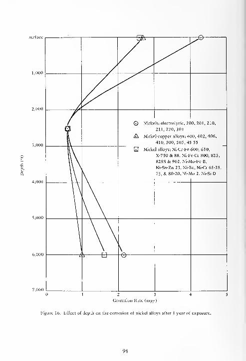
surface
1,000
2,000
3,000
5,000
6,000
2 3
Corrosion Rate (mpy)
Figure 16. Effect of depth on the corrosion of nickel alloys after 1 year of exposure.
94

© Nickels; electrolytic, 200, 201, 210, 211, 270, 301
A Nickel-copper alloys; 400, 402, 406, 410, 500, 505, 45-55
EI Nickel alloys; Ni-Cr-Fe 600, 610, X-750 & 88, Ni-Fe-Cr 800, 825, 825S & 902,
Ni-Mo-Fe B & 2, Ni-Sn-Zn 23, Ni-Be, Ni-Cr 65-35, 75 & 80-20, Ni-Si D
12 3 4 5
Oxygen (ml/1)
Figure 17. Effect of concentration of oxygen in seawater on the corrosion of nickel alloys
after 1 year of exposure.
95

Table 26. Chemical Composition of Nickels, Percent by Weight
Alloy Ni C Mn Fe S Si Cu Ti Other Source"
Electrolytic Ni 99.97 + Co - - - - - - - - INCO(3)
Ni-200 99.5 0.05 0.29 0.04 0.006 0.07 0.02 - - CEL (4)
Ni-200 99.5 0.06 0.25 0.15 0.005 0.05 0.05 - - CEL (4)
Ni-200 99.5 0.06 - - - - - - - INCO(3)
Ni-201 99.5 0.01 - - - - - - - lNCO(3)
Ni-211 95.0 - 5.0 - - - - - - INCO(3)
Ni-270 99.97 - - - - - - - - lNCO(3)
Ni-210, cast 95.6 - 1.0'- - 2.0 - - - INCO(3)
Ni-301 94.0 - - - - - - - 4.5 Al INCO (3)
Filler metal 61 96.0 0.06 0.30 0.10 0.005 0.40 0.02 3.0 - CEL (4)
Electrode 141 96.0 0.05 0.25 0.30 0.005 0.60 0.05 2.2 0.25 Al CEL (4)
"Numbers refer to references at end of report.
96
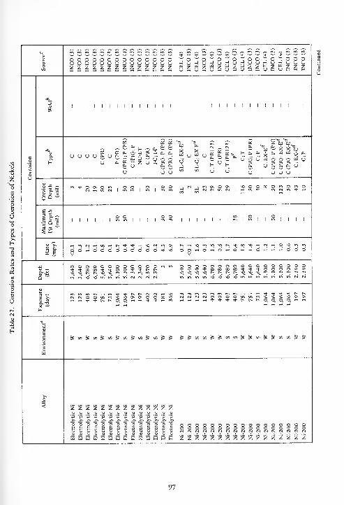
3Oen
ooooooooooooocjcjcjcjcjcjcjcjcjcjcjcjcj
cuz Id
cj
INCO
(3)
CEL
(4)
INCO
(3)
CEL
(4)
INCO
(3)
^8cj s
a- w^8u a
8^ oCJ2
JwCJ
INCO
(3)
INCO
(3)
INCO
(3)
co
o
ou
1 1 1 1 1 1 1 1 1 1 1 1 ! 1 1 1 1 1 1 1 1 1 1 1 1 1 1 1 1 1 1
D.
£ £~ ^ ~ ^ l_ ^ a, ebOS a; a, jjcq o: i a.
CJ 0. « ~ Z CJ i «i U a.
2a.
cu
2a.
CJ
wXu
Ven
hi £j
U W U £ a-
« CJ
fsl
s «>
H6"
£0-
CJ
T3wa
- XU H
6"
OS UJ ft]
°* s> s^— X X ft]
a. w w a.
£ £ £ u.u
cl o. a. cj
CJ CJ CJ
m ri- O Os O m OO , O , ONiiinc4l.v>in|in|m oen
N , (N OS OJ (N r- m S i
SO O O 00 os
O rn Om •* -i
I 8-3 o o oIllll|min||||<n c1 1 1 1 I 1 i
Sis
1 1
O1 1 1 1
2 s
^mCjT-Hmr^t^^^-r-IVOtSlA OS t^ t-h \0 m SO SO t- •+ 00 ^O rt (S) ,_, o so in in
OOi-iOOOOOOOOO*V
so o O iH O <-i oV
rH O O iH ~ rt o o o
oooooooooooom^-^-oow'*'*-oo-*-*r^t^S0s0t^r^s0s0«1(nmfnmmm o
so
o o o o o* * -t 00 »so so \o t^ r^
in in m so so
o o00 00
so so
O OSO SO
o o* oso m
oo
oo
o o oo * •*
in (N (NInvi^^vilftl/IVIMMNN
o aa- -o
W
rommmr-HWTi-Tj-t-~f*rsi(N-HfslrslOOmmsOSOOsOsOOOO SOSO s rj <N (M o O
_, rt r-l -* ^o o
t^ t-m sob» 0_
so
p.
so
q'(h t^ l>SO Os OsO, rt y-l
c
1co
>c01
5diS9iJ"iS"iJ''i^'''? & & ^ « in S S en en & =s en ^ & en en & &
>s
<
oo
o o o o oo o o o ocsi (M (sj (N esi
o oo o(N (N
O oo o(S (N
o oo o(N (SJ
ocCsl
ooCM
o o oo o o(sj (N fsj
ZZZZZZZZZZZZZ Z
oooooooooooooS5SE55335E53E 5 Z Z Z Z Z Z Z Z z z z z z Z Z Z Z
97
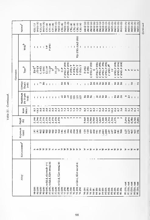
_ ^ ^ *^ >>
<*- ~ * -t- <* -r ^ ^- Tj- ^ — Tj- •* * *u "O" c w s^ w o o " o o -;
—
<
ooooooooooooo o o o o o3 J o J u J -j -] y y ;J y y J — — — yuyyyyyyyyyyy y y y y uC/5
U V wu - u z u y y zzHzzShH M U M M U
~ — —y y y zzzzzzzzzzzzz z z z z z
£cu
N
I I I 1
a.2-
I1 1 1 1 1 1
<1
X. 1 1 1 1 1 1 1 1 1 i 1 1 1 1 1 1 1 1 1
SC/5
cu £Cu
CO
os x a: cfosoSBS esoia;cu cu c— E-i H H cu i a. t i.^ cucucu
ts f- H a. a. IXtq uj w K -u•^ «w cu CU cu '-? — — — c^s.i.i.^..s.i.a.
iSTS' 2'£££Si""£££c a.
f- W 2 0"
cu
yDV D u ££i
OS BJ ft.
rx a, a,cu a, y a y
o Cu Cu cu CU CU CLi Cu CuCUCUCU CuCUCU
yu y u yyyy yyy
o J- -* en c,o o o
, ,ooooooo
, ooo O m*> a.
*p1 1 1 1 1 1 1
in in * I 1 I , IImcMcncnminmlmmm
1 1f-
1 f»
e £3 a." in o O tn ooo.oooo, ,ooo CO en
e u .-=1 1 1 1 1 1 1 I 1 + in * N CM CM CM inminlrcminml |inmin CM 1 | |
| Q E ~* ^ ^ *"*
S £
^
(S £
in rf vO o CO M3 N h D\ M m ^ m o\ m inmt^cMt-icMWrnin^HsOt^O O iH CM m en
o o o o O O o O O it I- * rH O'-'OO-HOOOOOO^O'n N Hh O"V Vw
o o o c o o o O O m in in m in in in OOOOOOOOOOOmm O O O O O* * t- t^ r^ r> r- [^ t^ *+»t»*'tOO + + N t i- w M ^t
cmc^cm rM - CM M «"MDMOt^I^sOvOcrirCicncnm \q mo r^ r>-_ <^
in" >n so -o" inminvo^oinininincMcMCM
1 Xr-~ r~ cm CM CM cq N N H H ^O OS O O CO mrOf^m^Hwtf^-r^r^CM^^Oo\ o\ o O o o o O O CO CO mo CN * + CO CMCMOOmmsOMDOOOooO cm cm O O m
O rt rt rt + -1- * -f- * rt- <j- ,-, rt m m -H'HTj-Ttr^i^oO'-i-H^-'Hfn -h rt «4- <* r»a- -a rt rt
m
vc
EC n « ^ & ES 5t in tn t« & 5 & 5 S =s =s 5'"J»coj»tn-it/'E5f&Ji-S 5 <n -S c/2 -5
*>
cW
rt rt rt-h VO >o MD
2 2"5
^ Wp E E E
r1
Ji — —X_o
<
5 1
tj
1
a"
S 3 rt « «
o o o o o"3* o o o o o o o o o" o o o o o oo o o c o O o o o o o o o o o o ooooooooooooo" " " CM *? CM 7 N N N N N N (N CM CM CMCMCMCMCMCMCMCMCMCMCMCMCM CM CM CM CM CM
z z z z zZ Z Z z Z Z Z z z z z z z z z z z z z z z z z z z z z z z

3
mmmis-immmrnro mmmmrnminmmmmmmm m m <s-> rn m rn m m m m
ooooooooouuuuuuuuuZZZ2ZZZZZOOOOOOOOOOOOOOzzzzzzzzzzzzzz
o o o ouuuoz z z z
o o o o o otj U (J U (J uz z z z z z
co
o
o
S1 1 1 1 1 1 1 1 1 1 1 1 ! 1 1 1 1 1 1 1 1 1 1 1 1 1 1 1 1 1 1 1 1
•a
a.>,E-
°~ &• - 5 ,„ a- 0".. o. - - . (J U - -V U sJ J u u
Z tn
c C;PC(PR);P(PR) C C(PR) C(PR)
C
(PR);P
(PR)
C(PR);P(PR) C(PR) I-C C(PR)
I-C;
I-P
C(PR);P(PR)
C
(PR);P
(PR)
C(PR)
I-C:
IP
C;PC<PR);P(PR)
££££££O, O O. Oi CU Oh
(J u u u u u
o J2 ^8 8-1
IN so so <N <M--£=>
1 -—> 1 - 1 nm IN00OOsOOOO<N , o , oofN<Nm<Nmis-,minm
|in | m in
O ,rt O
in 1 ol •<*o o o <3 o oin m in rt- in m
1 a.
O M O 001
"-. —I 1 1 1 1 ". -o
o o o o o1 1 m 1
1 | m in 1 1 1 1in in
1 1 -1 * 1 1 1 1 1 1
5 e
r^incsso.-ir^mo-'t rnoOOOCslrnmOlNini-isOCNOm so m in in 00 t-i t-i o m IN
r-trtOOOOOm"!V
OOOO^O^HOOOOOmTj-V
OO^O-* N n +nn N
Q wOOOOOOOmiA* O O •<*- -<1- IN p.so >n m m m rn m
OOOOOOOOOOOOmmi-'J'OOOS^'tOO^'+^NsOsOtNiNsosommmmmmO O <n m1-- in
O O O O o OTh + 00 00 * •*so so in r~ so so
in in so sO in minmsosomminincslfslfsicsl
1?a. -ox ^
7511,064 1,064
197 197 402 402 181 366 CsiCstOOmmsosOOsOsOOoOso^H^^-^-t^t^O_0^^^'* ,*'-i pr>
N « H -Oo o oo so,* * ,-. m rg rsl O O in in
.-i .-i tJ- <3- in in
£
o
cw
(/5&(/)^C/>^C/3SS JinJ«Si/)J»iS»iJtnSJ .5 c/5 «J =S ^ i« is « j5 Ifl
<
o o o o O O O o o ooooooooooCslCsirslfslrsl»MrsltNrl NN«NNNNNNNMMNN N « N Nzzzzzzzzz zzzzzzzzzzzzzz z z z z Z Z Z Z Z Z
99
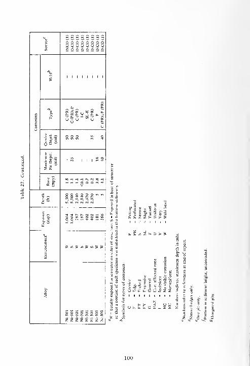
~ ~~~^^£££! oooooooo3 uouuuuuuin zzzzzzzz
a33
S1 1 1 1 1 1 1 1
^a;
a. &-O K2K ,,u b; a.
c
u — <jOT u *
o
(J 0-
o uU
u -C *-, O O O >n
1 8-16°-ui m ir.
| |m | rf
E -5
f Q E
<n x1
<*> 1 1 1 1 « *
5 S
^
(S E
oortrtrtt^<N«rt
V
j. OOOOOOmirt°~ 2 O O "d- * t» r-
Q w m m NN N N
u3 T *t'+t>t^r>jcsrtvoa ^ ^O^OOOvOOOOOO rt O^ 0_ rt rt t)- -* -1 mO- T3
U
Bc
1co S«SlrtSl/5gS">
cu
>N
<
ooooooooZ Z Z Z Z Z Z Z
|
S _ESa ° S |. | £ b2
OS J -,0-CUt/5C/5HD>?E j
su E c
cn
E
S
5 s.a
E^
</: x:
u T>>
15 :| c 3E:
t
"c
>T1
-55
cs c
> cn tj
U W W UJ O - z X.x .9 5s
>, a_ 0.'r
H X < u L> 3« (J u W u O X _ z Z z
100
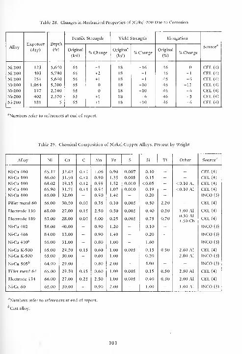
Table 28. Changes in Mechanical Properties of Nickel-200 Due to Corrosion
AlloyExposure
(day)
Depth
(ft)
Tensile Strength Yield Strength Elongation
Source''Original
(ksi)% Change
Original
(ksi)% Change
Original
(%)% Change
Ni-200
Ni-200
Ni-200
Ni-200
Ni-200
Ni-200
Ni-200
123
403
751
1,064
197
402
181
5,640
6,780
5,640
5,300
2,340
2,370
5
65
65
65
65
65
65
65
-1
+2
+ 1
+ 1
+ 1
18
18
18
18
18
18
18
-16
+ 1
+ 1
-10
-10
+4
+ 10
46
46
46
46
46
46
46
-1
-4
-13
-4
-5
-4
CEL (4)
CEL (4)
CEL (4)
CEL (4)
CEL (4)
CEL (4)
CEL (4)
"Numbers refer to references at end of report.
Table 29. Chemical Composition of Nickel-Copper Alloys, Percent by Weight
Alloy Ni Cu C Mn Fe s Si Ti Other Source'7
Ni-Cu 400 65.17 32.62 0.11 1.06 0.90 0.007 0.10 _ _ CEL (4)
Ni-Cu 400 66.00 31.50 0.12 0.90 1.35 0.005 0.15 - - CEL (4)
Ni-Cu 400 68.02 29.25 0.12 0.99 1.52 0.010 <0.05 - <0.10 Al CEL (4)
Ni-Cu 400 65.90 31.75 0.14 0.94 1.07 0.010 0.19 - <0.10 Al CEL (4)
Ni-Cu 400 66.00 32.00 - 0.90 1.40 - 0.20 - - lNCO(3)
Filler metal 60 66.00 30.50 0.03 0.35 0.10 0.005 0.50 2.20 - CEL (4)
Electrode 130 68.00 27.00 0.15 2.50 0.50 0.005 0.40 0.30 1.00 Al CEL (4)
Electrode 180 63.00 28.00 0.03 5.00 0.25 0.005 0.75 0.700.30 Al
1.50 CbCEL (4)
Ni-Cu 402 58.00 40.00 - 0.90 1.20 - 0.10 - - INCO(3)
Ni-Cu 406 84.00 13.00 - 0.90 1.40 - 0.20 - - INCO(3)
Ni-Cu 410* 66.00 31.00 - 0.80 1.00 - 1.60 - - INCO (3)
Ni-Cu K-500 65.00 29.50 0.15 0.60 1.00 0.005 0.15 0.50 2.80 Al CEL (4)
Ni-Cu K-500 65.00 30.00 - 0.60 1.00 - 0.20 - 2.80 Al INCO(3)
Ni-Cu 505* 64.00 29.00 - 0.80 2.00 - 4.00 - - INCO (3)
Filler metal 64 65.00 29.50 0.15 0.60 1.00 0.005 0.15 0.50 2.80 Al CEL (4)
Electrode 134 66.00 27.00 0.25 2.50 1.00 0.005 0.40 0.30 2.00 Al CEL (4)
Ni-Cu 60 65.00 30.00 - 0.90 2.00 - 1.00 - 1.00 Al INCO (3)
"Numbers refer to references at end of report.
Cast alloy.
101

3
U-SsJSUUUUUUU-1 j
— Tj" — ,j. ~-
o ~ o ~ ot) -J u -J (J7 W 7 W 7- u - u « S — ususu — Zu — u — u
— *
7 w- CJ
C_o
u
5i i i i i i i 5; j d d i 1 1 1 1 1 1 1 1 1 1 1 1 1 1 1 1 1 1 1 1 p
in
a.V D cu <V
w.
D D T. D . - ~ ~ * <* D D a.
D cu... W W ^£ Cm"
D. Cm" £
Cm .- n -Cm~ <J ^ (J ~u U
C;ETC(PR) C;E C(PR);P
C
(PR);P
C
(PR);CR
C;P C u C p C(PR):PE;I-P
H CmW —
a. 0.
5j j= ~
1 s-'l iiii"**"*iiiiiS O O N «o mosoomo^r^, .-si-.o,rH * >t N + rf || 1*1 1 1 1 1
3 a. ~
1 s
i i i i i i
~i i i i s i S i 5 i iiii^iS'ii'Sii 1 1 1 1
(5 B
»*min**m* + 'ni«>>n » + H O H rtfftOOfi^O^^'tO^NtCO'" _ ^ in TfOOOOOOOOOOOO O O O rH m O—iOOOOOO—iOOOOO O O O O
Q wOOOOOOOOOOOO•*-<)-^-^|-Tt-000000»SOsosososoOsOsOsOsOsOst^
O O O O OCO O0 00 't *t^ t^ r^ so so
00000000000000't-st-OOO0'*'st--d-**t~t^t~•O^OrnrnmrnmmmmmmmmO O O O
»,« mmm «, nlnn «l«« so so so in ift inmiftiftininNfjMMCSNMN N N rsi M
3 ~a
a. -ax —•
w
mmmmwiOsOsOsOsOsOsffsNMrJNNCOfflMOOMKO O O O ui <n* Th * ts i-«
irsinsosososoOsOsOsOsOsOOO O OCs] Csl
O O
c
Eco>c
5SSuil/)Sl/lS"lS<'l5 Jlfl«^^S»l->J(/HOj^S»)OlSSl/l 1/5 5 s s
>s
2<
-Cu
400
-Cu
400
-Cu
400
-Cu
400
-Cu
400
-Cu
400
-Cu
400
-Cu
400,
long,
butt
weld,
electrode
190
-Cu
400,
long,
butt
weld,
electrode
190
-Cu
400,
3-in.
circular
weld,
electrode
190
-Cu
400,
3-in.
circular
weld,
electrode
190
-Cu
400
o o o o oo o o o o*-*++*3 3 3 3 3u u sj y y
OOOOOOOOOOOOOOOOOOOOOOOOOOOO33333333333333yyyyyyyyyyyyyy
O
UTJO
0"
0"
* •*
3 3
1 I
-0 -0"
a 2u v
0" 0"
O O3 3
zzzzzzzzzzzz z z z z z z z z z z z z z z z z z z z z z z z
102

uu-uu-Suuuu,
w ~^^" OOOOOOOOOOOOOOWWU, zzzzzzzzzzzzzz zzzzzzzzz
I D D I I I I I I I I I I I I I I I I I I I I I I I I I I I
—»f* cu cu
u 5i
U 0- D D D VV - u u a- D YO V OS V * '* <* u
<~> 5j 5j Zu u
ct) a2 BS «CU Cu Cu Cu (J
I* nO
I I
o o o o
3D.—I si I rg ^, rf rt rt
*-i<NNOOO\t-~OOC\I I I I I I I I I I I I I I
S. B
Tj- NO 00 I> OOO^hOOO'-'OOOO o o o o o o o
ooooooooooooM M -t t O O ,tvO r- ^ ^ ^ "i m„
m.
ooooooooo
^h^h^vOOOOOOOOCN * **" 00 (N M O
^H _| tJ- rf r- t^ m _l ,_, ^. ^- t*s
O m v» -O \0 OnTt- r- t- O O t-<
££££££££££ £c/>£t/>£t/)£c/D£c/i£</>££ £c/)£c/l£t/)£cfl£
? B
OCOOOOOOOOO MC4MINCNooooooooooo ooooo*t*t-rjr^tTt-&'f'3-*t*t-*t- *+ ^*- ** -*"
33333033N N N
_ o o oN N M n N N \o\0--ONO ,0'O vO vO vOoooooo ooooooooo
3 3 3 3
V V Vz z z
yuuyyu yyyyyyyyyyyyuy y y y y yz z"
'£ z z z z z z z z z z z z z z z z z z z z z zV V V Vz z z z
103
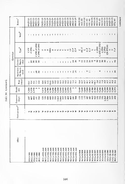
3O1/5 INCO
(3)
INCO
(3)
INCO
(3)
INCO
(3)
INCO
(3)
oooooooooooooozzzzzzzzzzzzzz zgzggzzzgzzzzzg
Co
| I I I 1 1 1 1 1 1 1 1 1 1 1 1 1 1 1 1 1 1 1 1 1 1 1 1 1 1 1 1 1 !
a.U-ET C(PR) C C(PR);P(PR) C(PR);P(PR)
c ETiC c C;P C;P c c C(PR) C(PR);P(PR) C(PR) C(PR)
CR
(PR30) u u C;P
"> a. •=
£ a ~o o o o 111111111111*° ONT-.rtVO^OOOlNOmOO,
,o
_, ,-, rt <s rf mvomml| |
•*
Maximum
Pit
Depth
(mil)i i i s s i i i i i i i i i i i i 2 2 iii^^iii^i.iiiiS
« Eh >q H in qo d d h- <>
Vdd>-<dd66c>dc>c>c>»H'«
V
Tj-r-.tNT-ir|fo-Hvo^ino;^ ,tN ,ododddodmOHodoodV
JC
2,340 2,370 2,370
5 5 OOOOOOOQOOOOmin OOOOOOOOOOOOOOO+'*-+ooMoo'+*'i-oo-*'*t^inmOvOt^mmmrMfMiNfN inwminwi^iOviifiinniftNNN
3 •-
O ri
a. -aX *~111
r^ n (N »-h <©CN O O 00 Oh * * r-t m (NMOOul'n'-O^OOONOOOOO ^H^H^H^H^Htj-Ti-t^r^C^O_O^^^H^-
1o'>
c
ui 5 en 5 & jTiSiflSuiSaiSai^i'iSS ^^C/)^C/5^C/3S^^SfSt«&
<
Ni-Cu
406
Ni-Cu
406
Ni-Cu
406
Ni-Cu
406
Ni-Cu
406
OOOOOOOOOOOOOOOOOOOOOOOOOOOOOO333333333333333yyyyyyyyyyyyyyyiz Z Z 2 2 2 2 2 2 2 2 Z Z Z 2
oooooooooooooo*<t'*Tt-T)-Tt-'j-'3-*i-Tt-Tt-'*-Tt-'i-33333333333333yyyyyyyyyyyyyyz z z z z z z z z z z z z z
104

uu — £ £ * ~ J rr * — * * K
!". * + en mmmmrnmcnmrnrnmmm m m m m m
O "O o T "T cMEL
I
CEL( CEL(
o ooooooooooooo o o o o oo tj 13 "5 J U -J J _) (J J J u u UUCJUUUUUUUUUU U V u u uv: Z J3 j= W 73 C/> C/3 U -
Ed
u7- H Id3 U CJ
z z zzzzzzzzzzzzz z z z z z
^ _^09 Ns £<
1 1 1 1 1 3 D 1 1 N 3 1 1~ x
1 1 1 1 1 1 1 1 1 1 1 1 1 1 1 1 1 1 1
£ < pa «I 5 £0. 0.
^ ^a BSa, 0- a.
O- & o O j gu
a.
a,a. -
(J
a.a. a.
Oi0" a. a,a.
p DDVpDOUDDU^ga, OS OS . , OSa. cj a, V a.
B (- 2 £ U U UO 0. 0. (J
u u
u " -5 ~ O O r^ r^ CM o , c O * O ,cm
1m 1
|mo 1 1 1 1 1 1 1 1 1 1 1 1 1 1 1 1
in cm m | M3
E £3 O.,-.EJJ3 -t- >H 00 O CM 00 o m o en
1 1 1 1 1 1 1 1 1 1 1 1
rn1
1 1 1 1
§°s 1 1 I ^ I ^ CM m *-+ en en CM -H
1 s
„m CI.
« EO M3 m m iH -o in o * o\ ~h vO * H » * *o\rfO<-HOmocMcnrtc-rt O i-l O -I ON
O O O O O o O -I «OH H iH O cm-iO-hcm^OOOOOO,-! en CM m O *V V V V
j= o o o o o o O m „ mm in in in in o OOOOOOOOOOOmin O O O O Or- r-» t- r-» c> r~ t^ * rl-oox^-'tOO^-iJ-c^t^ + *»» +
Q ~ VO \Or~C~sOM3mmmmmminMOvomininincMcMcMcM
iO ^O N N 'Oin in -o M3 inCM CM CM CM cm CM CM
u a1 >,
CM ^ M0 so o o mmmT-i^Tj-'3-t-~t^cMCM,-ivOo o o o o o O 00 00 X 00 \0 00 * vt- cMOOmm\OM20\GNOOcosO CM cm O O «n
rt •t * -3- * -4- ± * -1 ^-*Tj-c~t^oO_^^<ir->)--Hcn iH rt * * »O- T3
u
BC
EB
B
^ ^ OTj C/3 C/) & s s =£ S s= St S £ 5 st ooJ:c/55</'si'n st«s: ^5st S oi 5 i/i S
-r* rn ^O m^MO ~
2 U Ma TO a a a «i
o O o E 2 «>.
<aa
-a
TO
>
a -o
T) TOa. w
o o o o oo o o o o
so
o" oO O o o" o"
o o oz.
oo o" o"o o o
° CJUUUUUCJUUUWUUo OOOOOOOOOOOOO o o o o o
a 'x m a a j: * * « X X us JL -jL -j£ MD M0 MD MD M0
3 3 3 3 3 3 3 3 3 3 3 3 3 3 3 3 3333333333333 3 3 3 3 3U U U <J u 9 o u V V V CJ vvv zzzzzzzzzzzzzz v V u V V
z z z z zz z z z z z z z z z z z z z z
105

3 O O O O OO (J U U U Ucn z z zz z
-o1
2M
1 1 1 1 1
-a 2 2 p-a. (X 0. U <j 3
c.0
(- o u 6"
o
oU Si J= ^
(S <N m r-~O *> m hI£ frl
Sa-5
E £3 a. ~
151 1 1 1 1 1
1 a
^- c- m Tt oi in rt
* §,-i ^ O O O
5 „5,640 5,300 5,300 2,340 2,340
^ 3D w
a3 *~. ^H * * t^ t^
s ^ tr> \Q \o O* G\O rt t» q. o_ »-i t-hcl -ax ^w
<3^
c
1co
C/5 S C/5 ^ C«
">
cttl
>,_0
<
Ni-Cu
60
Ni-Cu
60
Ni-Cu
60
Ni-Cu
60
Ni-Cu
60
J=a. wx ctd-
ii
T3
3 .1
.JjC 60 2 u g XI
S. g .3 o S <2 t)'3
o S 5 > c 1_. Z ill a. s/3 D Sii ii ii ii ii ii ii
Do; as
-. Z a, a. (/i 3 ^
.= EL H
u u u» ii ii
O w OUUUWWUX Z
106

^^ ^^Q r^ e-
Tf * ^ * -± U u <* + * * * Th Tt" *3
Of)
J J J J _l Q Q J J J J J J J wWWW w w < < w w w w w W w wo u u u o z Z o u o o u u u u
Uemc -ci -a -Q JJ
^H fS (V) * o -* no
c J3 g- + eg 1 1re eg eg
U 1 1 i 1 1 1 I 1
rtboCO
.5 ^[So s?
w-d- * + 5t- + o o * + >* * * * * e-•* -+ •* Tt- •* -i- -t- * Tt- <t- <*• ^1- * * ro
6~
oooc
-C -I «M eg irj ,-H ,-H eg no o r~ <* ^1- O rH *J3 + + 1 + + + + +
c U + + + + +u
C/3
2c o
> o\ On On <3\ On On o\ Ov Oneg eg eg el eg *• tJ- (M eg eg eg eg eg eg *
o
bfl
J3 CSic
rt N N N eg o O o o eg
O + + 1 + + 1 + I + + +
C/2
c C .Ou
!§> J2eg rg t>~ r» t-» f- e- CO
H e» p» r- r~ r~ oc X t-~ t-. r- r- r^ ^ r^ On
6
O O O o O o o o o o o o o u-^ Ox 3 ^1- 00 * c -!- -i- r~- e- r- r-» r-~ e~ r^ e~
\o e- \o
C3^ m no u-> m eg eg rg eg eg eg eg eg eg eg"
;
j
3 ^ •* e- r- eg eg eg eg eg eg ego >, eg O m SO (3s o\ o ~ o o o o o CO O3 rt i-l * e- q >* •+ -1- * <* ^1- * ^hX 3
(JJ
yo o o oSO \0 co
rt rtu It
qj u T3 -aB B O o
V u tj uU V
>^<4-1 ^v" 11 V
_o -a ts Tj" -ao u OJ u
< 2 2"u "53
253
2"53
ooo o o o O o c © o o" o" o" o" Oo o o c O c 3 o a o o o o O &+ ^ t •* -t" ^ <* -+ -+ <* >* * * -d-
3 3 3 - 3 3 3 3 3 3 3 3 3 3 3<J U O <J u u U U u U U U O u uz z z Z z Z z z z z z z z z z
107
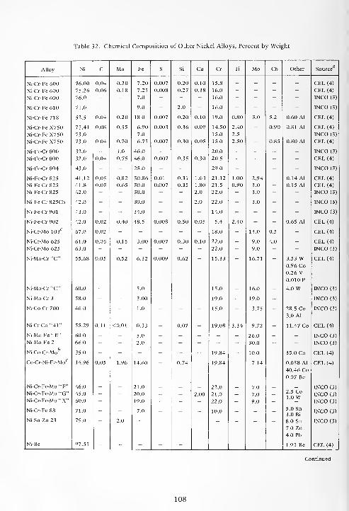
Table 32. Chemical Composition of Other Nickel Alloys, Percent by Weight
Alloy Ni C Mn Fe S Si Cu Cr Ti Mo Cb Other Source
Ni-Cr-Fe 600 76.00 0.04 0.20 7.20 0.007 0.20 0.10 15.8 - - - - CEL (4)
Ni-Cr-Fe 600 75.26 0.06 0.18 7.25 0.008 0.27 0.38 16.0 - - - - CEL (4)
Ni-Cr-Fe 600 76.0 " - 7.0 - - - 16.0 - - - - INCO (3)
Ni-Cr-Fe 610 71.0 - - 9.0 - 2.0 - 16.0 - - - - INCO (3)
Ni-Cr-Fe 718 52.5 0.04 0.20 18.0 0.007 0.20 0.10 19.0 0.80 3.0 5.2 0.60 Al CEL (4)
Ni-Cr-Fe X7 50 73.41 0.08 0.55 6.90 0.003 0.36 0.09 14.50 2.40 - 0.90 0.81 Al CEL (4)
Ni-Cr-Fe X7 50 73.0 - - 7.0 - - - 15.0 2.5 - - - INCO (3)
Ni-Cr-Fe X750 73.0 0.04 0.70 6.75 0.007 0.30 0.05 15.0 2.50 - 0.85 0.80 Al CEL (4)
Ni-Fe-Cr 800 32.0 - 1.0 46.0 - - - 20.0 - - - - INCO (3)
Ni-Fe-Cr 800 32.0 0.04 0.75 46.0 0.007 0.35 0.30 20.5 - - - - CEL (4)
Ni-Fe-Cr 804 43.0 - - 25.0 - - - 29.0 - - - - INCO (3)
Ni-Fe-Cr 825 41.12 0.05 0.82 30.86 0.01 0.31 1.61 21.12 1.00 2.94 - 0.14 Al CEL (4)
Ni-Fe-Cr 825 41.8 0.03 0.65 30.0 0.007 0.35 1.80 21.5 0.90 3.0 - 0.15 Al CEL (4)
Ni-Fe-Cr 825 42.0 - - 30.0 - - 2.0 22.0 - 3.0 - - INCO (3)
Ni-Fe-Cr 825Cb 42.0 - - 30.0 - - 2.0 22.0 - 3.0 - - INCO (3)
Ni-Fe-Cr 901 43.0 - - 34.0 - - - 14.0 - - - - INCO (3)
Ni-Fe-Cr 902 42.0 0.02 0.40 48.5 0.008 0.50 0.05 5.4 2.40 - - 0.65 Al CEL (4)
Ni-Cr-Mo 10 3C
67.0 0.02 - - - - - 18.0 - 14.0 0.5 - CEL (4)
Ni-Cr-Mo 625 61.0 0.05 0.15 3.00 0.007 0.30 0.10 22.0 - 9.0 4.0 - CEL (4)
Ni-Cr-Mo 625 63.0 - - - - - - 22.0 - 9.0 - - INCO (3)
Ni-Mo-Cr "C" 55.68 0.05 0.52 6.32 0.009 0.62 15.33 16.71 3.53 W0.96 Co0.26 V0.010 P
CEL (4)
Ni-Mo-Cr "C" 60.0 - - 5.0 - - - 15.0 - 16.0 - 4.0 W INCO (3)
Ni-Mo-Cr 3 58.0 - - 3.00 - - - 19.0 - 19.0 - - INCO (3)
Ni-Co-Cr 700 46.0 - - 1.0 - - - 15.0 - 3.75 - 28.5 Co3.0 Al
INCO (3)
Ni-Cr-Co"41" 55.29 0.11 <0.01 0.33 - 0.07 - 19.08 3.34 9.72 - 11.47 Co CEL (4)
Ni-Mo-Fe"B" 60.0 - - 5.0 - - - - - 26.0 - - INCO (3)
Ni-Mo-Fe 2 66.0 - - 2.0 - - - - - 30.0 - - INCO (3)
Ni-Co-Cr-Mofo
35.0 - - - - - - 19.84 - 10.0 - 35.0 Co CEL (4)
Co-Cr-Ni-Fe-Moc
14.96 0.05 1.96 14.60 0.74 19.84 7.14 0.058 Al
40.46 Co
0.07 Be
CEL (4)
Ni-Cr-Fe-Mo "F" 46.0 - - 21.0 - - - 22.0 _ 7.0 _ - INCO (3)
Ni-Cr-Fe-Mo "G" 45.0 - - 20.0 - - 2.00 21.0 - 7.0 - 2.5 CoLOW INCO (3)
Ni-Cr-Fe-Mo "X" 60.0 " - 19.0 - - - 22.0 - 9.0 - INCO (3)
Ni-Cr-Fe 88 71.0 - " 7.0 - " " 10.0 - " - 5.0 Sn3.0 Bi
INCO (3)
Ni-Sn-Zn 23 79.0 2.0 8.0 Sn
7.0 Zn
4.0 Pb
INCO (3)
Ni-Be 97.55 - " " " - " - - " - 1.95 Be CEL (4)
108
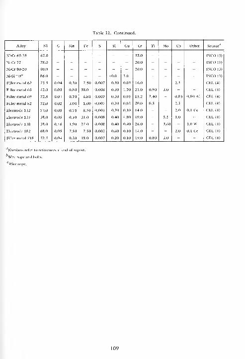
Table 32. Continued.
Alloy Ni C Mn Fe S Si Cu Cr Ti Mo Cb Other Source
Ni-Cr 65-35 65.0 - - - - - - 35.0 - - - - INCO (3)
Ni-Cr 75 78.0 - - - - - - 20.0 - - - - INCO(3)
Ni-Cr 80-20 80.0 - - - - - - 20.0 - - - - INCO (3)
Ni-Si"D" 86.0 - - - - 10.0 3.0 - - - - - INCO (3)
Filler metal 62 73.5 0.04 0.20 7.50 0.007 0.30 0.03 16.0 - - 2.3 - CEL (4)
Filler metal 65 42.0 0.03 0.80 30.0 0.008 0.30 1.70 21.0 0.90 3.0 - - CEL (4)
Filler metal 69 72.8 0.04 0.70 6.80 0.007 0.30 0.05 15.2 2.40 - 0.85 0.80 Al CEL (4)
Filler metal 82 72.0 0.02 3.00 1.00 0.007 0.20 0.02 20.0 0.5 - 2.5 - CEL (4)
Electrode 132 74.0 0.05 0.75 8.50 0.005 0.20 0.10 14.0 - - 2.0 0.1 Ce CEL (4)
Electrode 135 38.0 0.05 0.50 31.0 0.008 0.40 1.80 19.0 - 5.5 1.0 - CEL (4)
Electrode 1 38 38.0 0.16 1.90 27.0 0.008 0.40 0.40 28.0 - 3.60 - 1.0 w CEL (4)
Electrode 182 68.0 0.05 7.50 7.50 0.005 0.60 0.10 14.0 - - 2.0 0.1 Ce CEL (4)
Filler metal 718 52.5 0.04 0.20 18.0 0.007 0.20 0.10 19.0 0.80 3.0 - " CEL (4)
Numbers refer to references at end of report.
Wire rope and bolts.
Wire rope.
109

oo~~ooooo~ooo~o J Jy J U j8j IW 7 W cu a u o
i i i i i i i i I I I i
5
a. i-
~ &
UUuVuVo -a-°J 6- O O U H O w — Z •- ~ D x °<
u
B
Id1 8-3i i i i i i i i i i i i i i
rt rt ri o tHooooooooooooooo ^H ^H rt C-J t*~
d d 6 d h O rt o o
ooooooooooooooo+-*oocooo^-'*ooo-+'j-r^t^*o*oo\0\r^t^\o^o
(N M oo oo o ort rt r-l rH -^ >t
msOOOOCNOOr~ooo^HrtTt-Tf o o o oo oo
S»lJl«J»lJ»lJ^l/lJ(Oj^ ^ Cfl Cfi ^ S & & =S
oo
ooaoono
oSSO
oo
oo
oc
ooNO
ooNO
ooNO
oo
oonO
oo o
ono
ooNO
u. - [fa [fa ft. [fa a. [fa [fa [fa [fa [i. [fa [fa [fa
(J vj u <J U u U V u '-J v U2 Z z z Z* 2 z z z z z Z 2 g z
o o o o o oo o o o o oSO ^O no NO no vo
W OJ <u o> u u[farN|[fa<N[fa[fa[fa[fa(S^m^oo^^^^M u rt y rt yuyyz z z z z z
y rt yyz z z
110
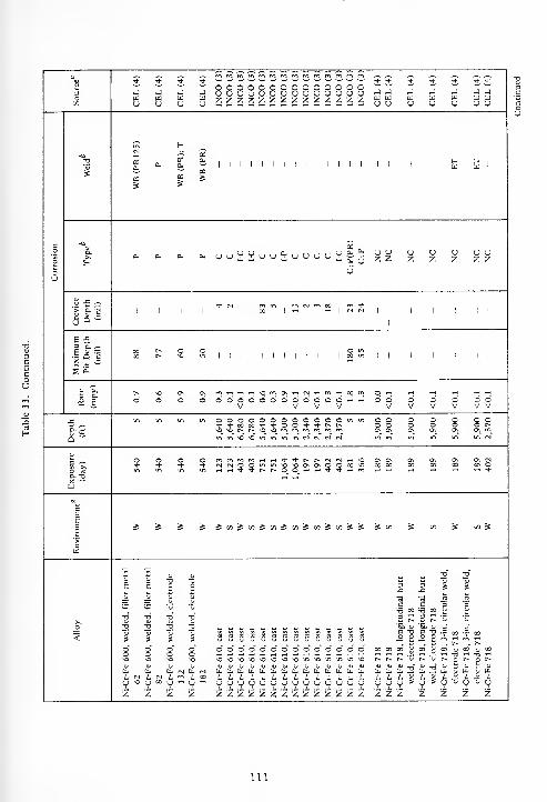
^ ^ ^ ^ ^* * •+ * * -i- * t * t *OOOOOOOOOOOOOO3 j -J j -J uouuuuuuuouuuu —
1
-J J _1 J _i -J
OU zzzzzzzzzzzzzz — —
H-Q
<N1 ^ £2S
5a.
Cfl
a.Xcu
CO
5
a.
ca
1 1 1 1 1 1 1 I 1 1 1 1 1 1 1 i 1 I
f"1
=S
B -o £
,
O a.
HCU cu cu cu — — »h ^ cu o
uz z z z z z z
6"
u
y -c ^*J- rsl mm m M fft 00 mrh
1 1 1 1 I1 00 1 -H rt | IN CNl
1 1 1 I 1 1
1
E -53 CL ~
15100 t^ o o O m00 t^ no in
1 1 1 1 1 1 1 1 1 1 1 1 oo m1 1 1 1 I 1 1
i £
^k ^ t^ no CN OS m^H^H^HOmON^CN^H^^HOOm o r-j ~H rH -H -H T-l
«
f
d d d d ddododdoddodHri d 6 d d d d dV V V V V V V V V V
j. in m m in OOOOOOOOOOOOmm o o o o o o o* + »e0"t'), OO + + Nt- o o o o o O r~
£•* NONOt^t^NONOmmmmmm a\ Ox 0s ON CK on mQ w intnvO^OmmtnincMcNcMcs m m m in m m rg
cUO S O O mmmm^H^HTj-^-r^t^cvtCMT-tNO ON ON ON ON ON ON N* * -t * (NrNOOminNONOONONOOCQNO oc X 00 ID 00 00 o
a. -oX wW
c
Eno S & & S j5onjSon^(n^infJ(/)-»u5->j> =s t/) S t/3 & 00 5*
>cW
S S a D g fcj
2 2"
E s p O 3Xi
3 3 1
c c 3 3*w
- ^ ^Lw_
3 oo t3 00
T3" a "O T3 2 S 3t^
"Q '5
<21
21
21
2£
a «c -oo o
c2 o 4 X c
00i/)t/)(/)t/jy}tfiwjvjt/itfit«i/iwiwj
C* C-*
o" d d o* o* o" d <d o" o" d <d o" o* o" <d o" o" 00 00 00 JJ oo" X CC ID 00o o o o "O a '-i
no o o no ^o^o^o^o^o^o^o^o^o^o^o^o^o^o c^ t^ tx <u t^ t~ o t^ O I~
£ 2 T3cu CU - (I. (N Cutt.eucucucucutt.cucueute,cucu Cu CU cu CU X u Cu
i. N N iL oo
V * 1u no V 00 V w V rt yuyijyyyyyvyyyu y V V u l> U u yz 2 z z zzzzzzzzzzzzzz z z z z Z Z z
111

u<u s•* T)- * Tt" + *^ ^ n_ ^ ^ •t *•ooooooooooo-o" "-r a t o o ~-r
o J J J J uyyyuuyyuyuT3yH H J y H y y H J Jw u m wu u y (J
ZZZZZZZZZZZ^Zg g u :7i
•7 W v 7 Ws u — — u
wy y
2a.
a U ,| y
<s <
IZ 1 ' Z 1 1 1 1 1 1 1 1 1 1 1 1 1 1 ^ 1 1 1 1 1 1 £
£ a,
N OS «< u yKH
^ ^ „a! sS £ £
IX a.
a-
Hy u u yz z z z
p; Di ^D U
-_ Cu o-< a-0.
0.
u u w k « b: a. £y
(_) a.
u u y U
o J= ^in m o o I** on w r^ no c*- NO *
, o o o o1 11 III 1
||rn i- | + * n ~, K || 1
rH1 m in m
1
U D "
E £3 a. ^
lei,o o o o oIII 1 1 1 1 1 1 1 M 1 1 1 1 1 1 1 1 1 1 I Iin in m
s s
^O n o o N >t rt h + »m in in
(S £ odd d dddddddddddddd d d d d d <^ d d d dV V V V V V V V V
j: O m in in oooooooooooooo o o O O O m in in in mt^ **oooo**ooo**t*t«. t* f- t^ 1^ t~ f-
a. 2"
Q w 2NONOr^t^NONOmmmmromr^m fn
minNONOininminmCNlCNfNltNCNi (N CN) CNJ Cn! PnJ
i >.
ts « o o mmmmT-HT-i-^-Tt-'^-^c^fScvlrv) cs cn* Cn> fN] ~H NO O O OO 00 * tJ- rvltNOOmmvo^OOONOsOOO O o o o o oo o + <t *O rt * ~ in in -Hrt-d-^-t^r-.0_OOrHW^t-^-Tj- t(- •t -t * •* ii m mQ. TO
w
Bc
|o S^5 5 5i«^w^i«$5tflSt«S5& 5 S on »i »i s S J 5 5>cw
a 73TO 73 o pO O
JJ
— JH M w <+* <U
u yTo" T3 -a a"
. •a" to"-a to •o TO
_o -a -o
S i 5 5< S i oooooooooooooo o" 6 o o o o o o o" d22 2 22
* t^t^t^t^r^t^t%i^t^t^t^t^t^t^t^o\ t^ t^ t^ t^. t^ r^ f~ i^. On r^t^ t— t^- r-^ XXXXXXXXXXXXXXX^ X X X X X X X X M3 X._ X — — — X i^i^iiiiiiiJiii 2 X X tt, i 'j. i — — — u. 00
UUUUUUUtJUUUCJUOU E EV s u u u ^ u rs u y o u y v y V r^
z z z z z z z z z z z z z z z z z z z z z z z z z z z z
112

uu ^ ^ ^
H ur
-J u u J
^ _mmmmcnrommmro m m rr> m m m m m m
3 oooooooooo c s i * — —- o o o o o o ouuuuouuuou u -J tj hJ >-) »J u u <J u u u u uen 2ZZZZ2ZZZZ z tel
Uto]
Utei
uW 7 W 7 7 W(J 2 (j s a (J u
to]
u z z z z z z z z
N 2£ 13 < a*
321 1 1 I 1 1 1 1 1 1 1 1
ft w1 1 1 1 1 1
xC.3
N< 1 1 1 1 1 1 1 1
& n23 CO X
CO.
-*>
50.
5ft
a.
zzz u zzz u zz ozuz z
uzh y u u y *
7".«VV"VVV
Bu 0. ft5u
o .c ^ w \0
Crev Dep
(mi III III II 1 1 1 1 1 1 1 1 1 1 1 1 1 i i i i i i i
E £3 ft/,
1 51CO CO X
1 1 1 1 1 1 1 1 1 1 1 1 1 1 1 1 1 1 1 cs (S1 i i i i i i i
i £
u ">^ oo o oS ft
2 E oooooooooo o O o O O O o o o o O O O O o o ovvvvvvvvvv V V V V V V V V V V V V V V V V
J. oooooooooo O o O o OOmminin in m o o o o o o o o* + aoo + *00 + + t> t^ t^ r^ r^ t-» * * x x -* * o oft ^ ^OSNOO^fimm & vO r^ r^ O <i rn mQ *"' mmso^OmmininrJiN r-J <N N N <N N in in >C vO in in in m
1 >;mmmrnrtrtTfTi-f^t^ M rq M CJ «S H w >o O o o m w m m w rt ^f *c,JC^OOtnin,000\ON o o o O O O X CO ^O tJ- >t -f N O O m in \0 ^O
O M rtrtTt-*r,t^oOrtT-, -t * * -t * * -h rt m in r-< -J- * 1^ t^ O O°" 3 rt rt rt ww
c
Eco ^U5^Cfl^(/l^«S« S S s£ =S i/i oi J 5 S S £ £ S to i5 on & c« S en
cto
a -o
o -6 6 T3>,JO T3 a -3 T3
< 1 S 1 I
OOOOOOOOOO O o o" d o o o o o o o" o" •* * i- * i- * * ^OOOOOOOOOO o 5 c c o o o o o o c C O O O O O O O OXXXXXXXXXX X X CO CO X CO CO CO 00 CO X X X X X W X X X Xuuyyyyuyyy U V y w y CO' y y y y y y y £ y N y y y y y y y y
E 1X
zzzzzzzzzz*
2 z z Z
— — — ~ — —
z z z z z zto,
Z z
to, Oft to, to. Ll, tu to. to,
z z z z z z z z
113
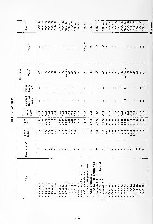
22C*=? V,
^ ,-. ^ ^ ^ .~. ^~ ^-. ^v ^ ^ ^^ ^^ ^^ ^^
3Oen
* w !". * ^ •* J ^ -t J j J ~ *- ~- "* w !2 ww ^--n1-—'*O O O O O OCJ (J u u u uZ Z2 ZZ Z CEL(
INCOMELi
CEL( INCO CEL(
-Jau
UJ
U-J
u-J
WU
INCOCEL( INCO CEL( ZgZZZgZg
-£> ?2 u u u
S1 1 1 1 1 1 1 1 1 1 1 1 z z z 1 1 1 1 1 1 1 1 1 1 1 1 1
0.c
o
Q. vvvv^v Vu u - u u uZ Z u z z z
z
uz
Uz
uz z
(Jz z V"Vu u £ u u u u v ciz£z-zz-J. u
u
Jj-c ^
IN ro X'£5-1 1 1 1 1 1 1 1 1 1 1 1 1 1 1 1 1 1 1 1 1 1 IN 1
NO1 1 1 1 1
C D "
E -53 a. ~1*1 1 1 1 1 1 1 1 1 1 1 1 1 1 1 1 1 1 1 1 1 1 1 1 1 I 1 1 1 1
s £
^J! >n
(2 £
.-( ^H ~H ~H ,-H *H O -H -. -1 *4 >H i-H T-H .H *-l rt O -H rt rt ^.^rtrHO^-H6 6 6 c> c> c> 6 d d d 6 d d d 6 6 6 d d d d d d d d d d d dV V V V V V V V v v V V V V V V V V V V V V V
_ O O O O m u-> o o o o o o o o o 0000 00000000Tj- * f« t» * + * * * o o o o CO 00 00 00 * * + + OOtN**
°-±; no no no no no ON ON ON ON on On c^ c^ t^ r^ NONONOmmmpncoa
-'rg" cvf ri csf «"><"«">« .ft m >n "> in NO vO vo no in ininiftininNNN
Kl~. ^ Cn] CS rH \o in (r> m m m ON ON ON ON ON ON m ^H^Hrt^-^-t^t-^t^on o\ o o oo no N N N N M » 00 00 00 00 CO O O O in uiu-imNONOONONON
-1- N+ ^" * f~ C^I^I^OO'-fTHrHa. -ax -*
w
ac
£c ^ c/) ^ en ^ ^ J J 5 "1 "1 S en s tw S CO S&cnco&S^oo^cofS^oo
c
tJ 23 3
-O 5 5
•a S Mc c 3 3'5 b~> 'B m3 3X a •Q
c c3 a 3 •a<
* * * + * *_0 ^ 2 "1 JJJ
o o o o o o M M N N N N r.i fN 'a <N 13 <N N N N N fNirsirMCNjCNirNirgrNi00 X X 00 00 X 00 00 00 00 00 00 00 =0 CO X CO X CO 00 00 xxxxxxxxyuuuyy yyyyoy y y 2 U — y y tl y y y y y yyyyyyyya. — x ~ — — ft. (l. ft. u. ft. ft. fe £ 1 ft. % ft, X ti, S ft. a. u. u. ft. ft.ft.ft.ft.ft.ft.bft.
2 z z z z 2 z z z z z z" z z z z z z z z z z ZZZZZZZZ
114

3Oon
INCO
(3)
CEL
(4)
INCO
(3)
CEL
(4)
CEL
(4)
CEL
(4)
INCO
(3)
CEL
(4)
INCO
(3)
CEL
(4)
CEL
(4)
INCO
(3)
MEL
(5)
CEL
(4)
CEL
(4)
CEL
(4)
CEL
(4)
CEL
(4)
CEL
(4)mmmmmmmmroooooooooouuuuuuuuozzzzzzzzz
c
o
5u
-0 ,,,£"! NC NC
I-P
(WB&HAZ)
N<X
I |
OS
u
1 1 1 1 1 1 1 1 1
a.>,t-
2 * v g g „ y °?m V u u o *h U °?, n,— y Z Z Z Z cj Z cj
QU
gg2SE.g§"$
'> a. ^ i2
i i i
oo m r^ -3-
1 « 1 1 | | in | N I 1 1 1 1111111*1
e -53 a ~
151 ill i i 11*1 1 II 1•«
* CO -t1 1 1 1 1 1 1 1 1
tS E o o o o oV V V V V
oooo o ooooo oVVVV V VVVVV Vo o oV V V
ooooooooovvvvvvvvvJ3
2,340 2,370 2,370 2,370 2,370
O O m in in in in in in in int~- r-
oooooooooTj-i-cocoi-'tooi-inmvovomminmcM
cUa. -a
w
r^ CN rsl cm r4o\ o o o o<-> $ $ * •*
402 402 181 181 181 181 366386°
398 540 540
O 00 00* 00 Oin in \Q
123 123 403 403 751 7511,064 1,064
197
1c
'>
cu
«ss s s wc/iSBs & J5SJJ 5 sss ^OD-JOO^cn^o-)^
<
Ni-Fe-Cr
825
Ni-Fe-Cr
825
Ni-Fe-Cr
825
Ni-Fe-Cr
825,
welded,
filler
metal
65
Ni-Fe-Cr
825,
welded,
electrode
135Ni-Fe-Cr
825
Ni-Fe-Cr
825
Ni-Fe-Cr
825
Ni-Fe-Cr
825
Ni-Fe-Cr
825,
welded,
filler
metal
65
Ni-Fe-Cr
825,
welded,
electrode
135Ni-Fe-Cr
825
Ni-Fe-Cr
825
Ni-Fe-Cr
825
Ni-Fe-Cr
825
Ni-Fe-Cr
825,
welded,
filler
metal
65
Ni-Fe-Cr
825,
welded,
electrode
00 00
•-> u. u.
z Z
Ni-Fe-Cr
825
S
(
Ni-Fe-Cr
825S
Ni-Fe-Cr
825S
Ni-Fe-Cr
825S
Ni-Fe-Cr
825
S
Ni-Fe-Cr
825S
Ni-Fe-Cr
825S
Ni-Fe-Cr
82
5
S
Ni-Fe-Cr
825S
115

3O
rommmrr, mmmmmrnmrnmrnrnmrnm mmmmmmmenmmmmmmo o o o ou u u u uz z z z z
oooooooooooooozzzzzzzzzzzzzz
oooooooooooooozzzzzzzzzzzzzz
c
u
51 1 1 1 1 1 1 1 1 1 1 1 1 1 1 1 1 1 1 1 1 1 1 1 1 1 1 1 1 1 1 1 1
a
hI-C;I-P I-C;I-P
1-C;I-P
NC I-C zz-IIzzzzzziz- ^. ^ — — ^. — j^. ^, / . — — —. ^, —
111 1 1 1 1 1 1 1 1 1 1 1 1 1 1 1 1 1 1 1 1 1 1 1 1 1 1 1 1 1 1 1 1 1
Maximum
Pit
Depth
(mil)1 1 1 1 1 1 1 1 1 1 1 1 1 1 1 1 1 1 1 1 1 1 1 1 1 1 1 1 1 1 1 1 1
2 E o o o o oV V V V V
oooooooooooooovvvvvvvvvvvvvv oooooooooooooovvvvvvvvvvvvvv2,340 2,370 2,370
5 5 OOOOOOOOOOOOmm*'+oooo'*'4-oO"t'*r>f^ OOOOOOOOQQOO>nin+-*oooo'*'*oo**t><^wm'C^iniftininNNNN «m>0 ,OintfiininN(NN«
h (-- ts r) —i *oo* o o oo "Ort tJ- -fr ,-, m 123 123 403 403 751 751
1,064 1,064
197 197 402 402 181 366 <N(NOOtni/>*O*O0\0NOO00*0
1c
'>
Bw
[« S 91 s s ^m^m^i/i^iiji/i^iii^ ^C/55(/5^l/5^l«St«&f&S
<
-Fe-Cr
825
S
-Fe-Cr
825S
-Fe-Cr
825S
-Fe-Cr
825S
-Fe-Cr
825
S
— — ~ — ^. — — — ^..Z^S.^^-
<NrJ<v)<N)M<N<NC^(N<SC*l<NrJfM0O0OCO00O000CO0O0O0O0O000O0O
bbbO,[i.(i,(i,biXbb[i.li,b,
OOOOOOOOOOOOOOONONOsO^OsOSOvOvONO^O^OsONON
yyyyyyyyyyyyyyhhbli.bli.hhli.bhli.liilii
z z z z z z z z z z z z z z z z z z z z z z z z z z z z z z z 2 z
116

„ „ „ „ „* * tc -* * * -t * * * <* N+Nj-^W^^^J. Ij-T)- rj- -*^|- tJ- Nt •"
^ ^ U U U U ^ *J W i-J -JJ a ^8W 7u a
3OC/5
J J -J J J J J J J -J J_____: ^ w a w w w WW7777W WW W WW w(J U — — — — nJ U <J U U U nJU V U U U <J u <j u u u
-KN
2 u u u U 1 1 1 1 1 1 U. (J U . US
1 1 1 1 1 1 I i z z z z 111111 z 1 z z 1 z 1 1
o a.
q a.a, a. ^". ". U U U * u u u u u UUUUUUU CJ U <J u u u u u
o z z z z z zzzzzzz zz z zz z z zu u ~o uu
Si -c ^in O no -< O m
1 £'g6 Q ~
in-i CN| rj rj- tJ- cn]1 1 1 1 1 1 1 1 1 1 1 1 II 1 II 1 1 1
E -53 C-~E a —|° E 1 1 1 1 1
t> 1 1, 1 1 1 1 1 1 1 1 1 1 II 1 II 1 1 1
1 £
-^
tJ- o Cn> m t^ in o o o o o rH -1
-H »H (N <N t-i w o o o o o 0000000 00 00 O OV V V V V V V
X O O in in in in c o o a o OOOOmmin mm in mm inr* r* o o o o o O c^ t^ r^ * *
ON OS On On 'On »nm "i NO NO
a w N n in" in" m' in' m' in" (n" n n" in" m
5 - <n| cni h *f m ro ON ON On ON On 0\ N N N H »0 00 00O O OX Xwi >N O O 00 no rs no X oo X X XOOOXnOOn OntJ- Tf * 00 X <s r\l
O « ^)- Tf ~< m r^ t-~ h * * * ^ m m m in in mm ina. -a
w
ac
Eco S y) s s s s S e/3 =S tn 5= « =s S </> =J g: =£ «t S =s 5 S £ 3= s
cw
2 2 -0 -0 -a3 3 I S 00Si J w ^ E t:
C^6
3 3,
elec
,
fille
,
elec
,
elec
>.
3 (N]
NO3
NO,;: a
Ided Ided Ided Ided
< ^o ap
_oap «
•0".
"° in in in m in in in in in" in" in in
o o o o o oOn ON ON On On On
CMno NO NO j NO ij
r!o a CN)
NO^rN](N(NCN]<N(NifM rNifNirgfNi CNirj^nQnonononononO NONOnONO nonO nJ <j
o o o i-OOOOOOO 00-730 00uSSSSSSSjnSSg^S??!"V V v w v s S S 13 § 13 s S § V V11 1 - 1 1 1 u V V ^ u y u y s s
z z z z z z z z z z z z ZZZZZZZ zz z zz z z
117

w * * *- ~ +J ° °
~ o o o o oU U U (J uz z z z
I I I I I I I I I I ! I I I I I I I I I I I I I I I
uuu uouuuzzz zzzzz
I I I I I I I I I I I I I I I I I I I I I I I I I I
I I I I I I I I I I I I I I I I I
5 E
rt H rt O rt O Qi-i-hO--iO.-iO-iO.-iO O iH O iH rt -H H O TH -I ,-1 H <Hooooooooooooooooooooooooooooo oooooV V V V V
oooooooooooooooooooooooo00<>r^r^t-*t^i©*0\0*OvOi^r'imrr>mmcnmmmf«min tfi in vo"^o >o \Q in ui w in in in" in in in n n* n N « n « N
V V V V
o o o o* 00 on^o r*. r^ M3
m ^o o IT,
<N ts o o o oH rt If * ^f +rH,-HT-1^H^HTj-Tj--<J-Ttt^r^t^^ <N J-t r-i SO 00 Xn0*O^0OOs0\0\OvOOOO0000*OO\Ot~t^OOOO>Hrt **** 1-1 rt rf -H ^ +
J»»i55»i»iiJJ»«iJJ»n«SJ»)uJJi«aiiiJJJ S <*> S « :5
<JU<JUUU(JUUUUUUUUUUUUUCJUIJU(JUUUU wmmmm00000000000066000666666666666 66666z z z z z z z z z z z z z z z z z z z z z z z z z z z z z z z z z z
118

o o o o n o o o o o o Tj n o o o o o n o n o o n n n n n nu u u u o u u u u u u U u u u u u u u u u u u u u u u :.j ^j u < j uZ z z z z z z Z z /. z Z z z z -i -d z Z. /. Z z z z z z z z Z z z z
I I I I I I I I I I I I I I I I I I I I
I I I I I I I I I I I I I I I
S £
•I Q B i I I i i i i i i i i i
1 E
o o o o o o o* O O * * l> t--
oooooooooooo3-^-oooo<d-'<i-00-*i--<f-t^t^
ooooooooo+ t00» + ')-OO +
m\0\0CKCNOO00O (Srt ^H •* * t-~
O o rt -h * * -H HHf + St-OOvOnOOnOOOOOnO *0T-. ,-C -tf- XJ-
o ^H^H*^^-r^r^oo
C/}^(/3^C/}^C/}^^ ^OI^C/}^C/}^C/)^Cfl^C/3^^ ^ ^Cfl^C/^^trt^C/}^
o oo oo o o oo oo o o o o o o oO O O O O O -h coaaacacacQaacapQ
u u u U 9 u u 'J 9 u o u u <J 'O u u u u 'J J u o It. fe b b u. •- b b bo o o '_ o o o o o o o o o o>r
>- £: Ife; >.-r-
>-. fe >. u <J V u u v V u u u !,) V V u u >- >- >- >. >. >: s s szzzzzzzzz zzzzzzzzzzzzzz
119

3O00
rr, m <*i m m rnmmmrr,rr>mmmroror«rr>m mrnmmmrnmmmmmmmmo o o o ou u u u uz z z z z
oooooooooooooozzzzzzzzzzzzzz
oooooooooooooo(JUUUUUOOUUUUUUzzzzzzzzzzzzzz
Co
o
u
-a
21 1 1 1 1 1 1 1 1 1 1 1 1 1 1 1 1 1 1 1 1 1 1 1 1 1 1 1 1 1 1 1 1
o. ™ O D O UV
OUUUUUUUOOO^e-o- <JU<J<J<JOUUU<J<JUUUzzzzzzzzzzzzzz
uQs/
1 1 1 1 1 1 1 1 1 1 1 1 1 1 1 1 1 1 1 1 1 1 1 1 1 1 ! 1 1 1 1 1 1
Maximum
Pit
Depth
(mil)
1 1 1 1 1 1 1 1 1 1 1 1 1 1 1 1 1
"* 2 1 1 1 1 1 1 1 1 1 1 1 1 1 1
as E <0.11.2 0.2 7.9 6.4
C*l,-irNrrt00v©M00O<N\O<^r^t-»^HWfNlO^OT-H"%^H»HO^HO^-Tj- oooooooooooooovvvvvvvvvvvvvv
2,340 2,370 2,370
5 5 ©OOOOOOOOOOOmin OOOOOOOOOOOOinm^-^)-0000'*-J-OO'*-+p»t^
u-iuioomu-iu-iinc^cjr^c^ Wlft^iCiniAwmMNNN
hD. 73X ^
t^ r*4 rj rH *oo\ o o oo oH + + HB1 rNCSOO^uiOOOvONOOOO^O Cvlc-JOOu'i«->'OO0\0XOO00O
rH.-i"3--+t--t-~0_0_ —1 rt ^- * rt m
c
s
o
>cu
oo ^ oo ji »S ^oo^oosSoo^oo^oo^oo^^ 5wJai^uiS»iSi/)5(/i^^
_o
<
Ni-Mo-Fe
B
Ni-Mo-Fe
B
Ni-Mo-Fe
B
Ni-Mo-Fe
B
Ni-Mo-Fe
B
00000066666666
OOOOOOOOOOOOOOtt5.a,s.tia.!i,B,iii.ii,ii,
yuyyijyuyijjyuyyyz z z z z z z z z z z 2 z zz z z z z z z z z z z z z z
120
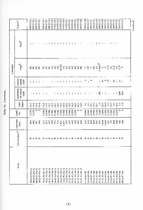
n n n n n n n o (") o o n o o o c o o o o o c o(
;
u ;
;
< i u u u ^J u u u u u u u u u u u 'J u u ^ u u u u u u u u uz z z z z z z z z z z z z z z z z z z z z z z z z z z z z z z z
I I I I I I I I I I I I I I I I I I
y v r. v * v ~ a.j - (j - u
I I I I I
& -5
i i i i i I I I i i i I I I I ICO I I I I I o
X B oooooooooooooo ooVVVVVVVVVVVVVV OOOOOO'H^-'
oooooooooooo oooooooooooo^^-0000'+'+OO*'J-t^I>\q NO N ^ \q ^O f^ m m rn rn rn
m in -o *o in in in in ri cs <N rvl
a. -13
o o w o MCvJOOmm>0'00\0\0000^H^HTj-Tl-t^t^oO^'-^'t'^-'-H
(N (N O O-. rt * *
O^OONOnOOOO^Ortl-l^-Ttt^t~00"-l^l^-Tt"-<
S in S S J«Si«Ji«JoiJ«iJbiJJ ^i«S«S«S'«&'«^''i^5:
oaou xxxxxxxxxxxxxxoooo ooooooooooooooh u. u. h [L.u.bU.tL.ti.b<(i.u.[i.u.u.tL,tL.
uy u 9 yyyyycjuyycjuyyu yuyyyyyyyyyyyz 2 z z z z z z z z z z z z z z z z z z z z z z z z z z z z z
t, - -i- - —
121
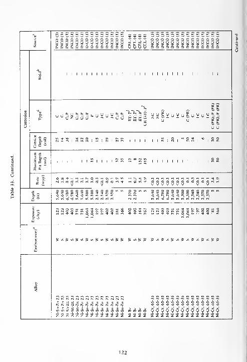
OOOOOOOOOOOOOO iii,zzzzzzzzzzzzzz gggg
n o o r. o o n O n n o ou u u u u u u u u u u u u uz Z /. z z z z z z Z z z z z
I I I I I I I I I I I I I I I I I I I I I I I I I
- u u E- H E- S Z Zy y £ vi.VUTUi.(JTuY^-^-
I I I I I I
t^ r^ t^ ooI I I I I I I I
.-H t- + o\
S. £ddddddddd o'o'oNrtVVVVVVV V V
oooooooooooo<i -o r^ t^ *o -o
OOOOOOOOOOOO*TfM00'+*OO^t-')-t^t^\q \o C^^ t^» so <l rn <"n ro rn ro rn
in in* sd *0 m in U1 in* <N~ <N* fS* CJ*
mosoov0\00«so OOsOsO fNrsOOO O ^ w <t ^- ^ •OsOOnOnOOOOso
t^ ^H THTl-Tfr^r^OO'-lr^'t't'-H
S»5«Ji«S»iJi/iJfflJJ "S(/5"£-£ ~Si/55f~5cS</)"Si/)-Sc/)^^
ccccccccccccccNNNNNNNNNNNNNNCCCCCCCCCCCCCCz z z z z z z z z z z z 2 5 z z z z z z z z z z z z z z z z z z
122

3Oen
oooooooooooooo(JCJUUCJCJUUCJUUCJUUZZZ2ZZZZZZZZZZooooooooooooooU <J CJ CJ (J uuuuuuuuuzzzzzzzzzzzzzz
o o o o o oU U <J <J o uz z z z z z
co
o
u
to1 1 1 1 1 1 1 1 1 1 1 1 1 1 1 1 1 1 ! 1 ! 1 1 1 1 1 1 1 1 1 1 1 1 1
CL
f-I-C NC C(PR) I-C
C
(PR);
P
C I-C C C(PR) C C(PR) I-CC(PR);P(PR) C(PR);P(PR)
c I-C c I-C C(PR) I-C c C(PR) C(PR) I-C;E C;P I-CC(PR);P(PR)
C(PR);P
(PR)
a. a.
o u 6- o o ~
Crevice Depth (mil)O ON N O in O , O O11*1-+ I-h^j- * 1 mm "i^sr^i^iSs N O m * Ov ^O
Maximum
Pit
Depth
(mil)o o
1 1 1 1 1 1 1 1 1 1 1 1"> "1 iiiiiiiiiiii°° 1 1 1 1 1 1
2 £2, e ddo'do'ddddddd-<'-iVV V VVV V V
OOOOOOOOOOOOtSwV V V V V V V
m + * ) Mfi
OOOOOOOOOOOOmm OOOOOOOOOOOOmm<OjNN^>Omfnmmmm
Q o o o o ot * CO OS * *vo \o r-* r~ o <o
in in O -O in inininsOOminininCMC*j<NN in^^OOininininMfMc^fM
hCL T3X -'(I)
fnmmm.-H^-<Tt-<3-f^r~fM<N~HNO04tNOOmin*0'OCNOOOOO*0 <N(NOOinin*O*OCNG\OO00*O n (N O O m m^h t-h Ti- 'I- t^ r-.
1co'>
B[I]
5t«St«St/)St/l5«5</5SS •Scn^eft-Sen^en^eO^en^^ 5 eft ^ en ^ c/l
o
<
OOOOOOOOOOOOOONNNNNNNNNNNNNNOOOOOOOOOOOOOOcooooooooooocooooooooocooox
yyyyyyyyuyyyyyQ Q Q Q Q Qen en en en c/) c/3
z z z z z z z z z z z z z z zzzzzzzzzzzzzz z z z z z z
123
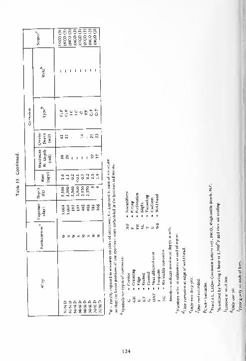
oooooooouuuuuyyozzzzzzzz
I I I II I I I
Ch 2-
Z Z, ^ w u u^ V V
E •£3 a. ~si
hhOOOONhV
s e
^- <<* r» t-<) *o Q\ ^ -O O H rt 't * H
a 'S -2. a
H D £
gc^S^S^^^ £ 5
H D SE j
x 5 >-
o
e3E
TJ X
5 F
KB
T3 a ^c .5
3>
<J U X c
>oZ
-5
c
2 -<
QQQQQQQQc/} c/5 c7) c/5 c/) c/} bn co
'f z 2 iz z z z z
<- "oUUWWOX — z S ^ -S "Ca o >. •-
124
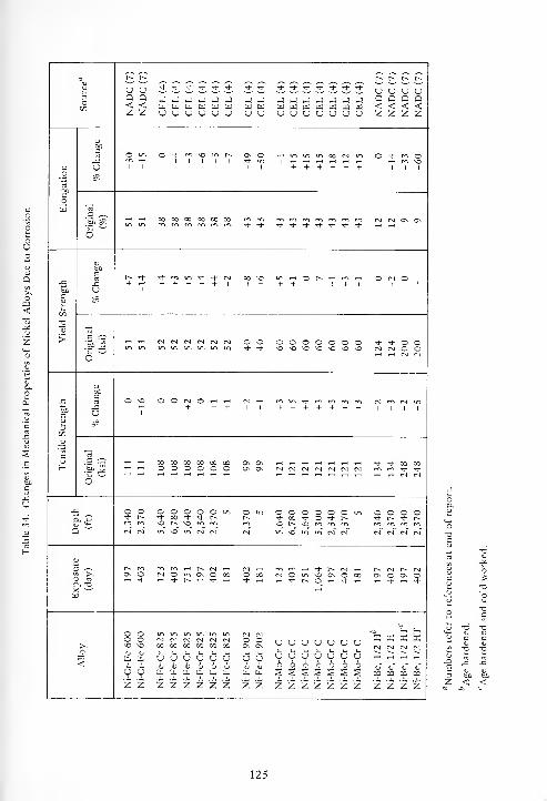
r~ r-- t-s r~ t» t-.
3oC/3
U OQ Q< <z z
Tt- * •>* •+ Tj- * Tt- Tt- Tt- Tt- Tl- Ti- Tt- Tt- * u u u uQ Q Q Q< < < <z z z z
J J J J J JW U W W u wu u u o u u
-J Ju u
rJ rJ J JHi td W (I]
U U <J Uwu
c
s
to
OO in O Tt- <-n no "", r^
1 I I 1 1
ON ©*• in
1 1
1 rH+
in in 00 CM
+ + + + +
O •<* m O1 1 1
^3j =SrH rH 00 00 00 00 00 00 * •* •>* "* Tf * Tj- ,j- * CM CM On On
O
boc
-CUbo
C
2
+ rHi- m m * ^ n+ + + + + I
oo no1 + + +
© t~- rH m1 1 + 1
O CM O1 1
> s ^
6~ s s
CM CM CM CM CM CM o oTt- Tt-
o ©NO NO
© © o oNO NO NO NO
©NO
•"*-*©©CM CM O OrH rH CM CM
bOc
UJ3
00cQJ
cuH
o no
1
O O CM O rH rH+ + + 1 1 + +
-d" m m m+ + + + +
CM rn CM in1 1 1 1
o3 JH
00 00 00 00 00 00o o o o o o
On OnOn ON
Tt- "* 00 00m m tJ- tj-CM CM CM CM CM CM
Q
o o O O O O O m<t 00 + * NNO r-» NO rrt rr>
O mmcm"
o o* 00NO t-s
O O O ©T|- O tJ- Isno en m m
- o o © ©+ N Tt ts
CM CM CM CMCM CM in no in cm CM in no in in cm CM
3 -~-
O £ On OrH Tj-
m m h is n hCM © in On O 00rH -Hr r-- rt rt rH
CM rHO 00Tt- rH
CM OrH rf
h i- f, Nin no On O[>. O rH rh
00rs CM r- CMOn O On OrH Tt" rH Tt-
<
o oo oNO NOIt oj
tL. [X,
u u
CM CM CM CM CM CM00 00 00 00 00 00
U u U U U UU 1> u u u uU. U. [l, Co, U. U.
CM CM© oOn On
U Uv (u
U, tt.
U OI- 1-
u u6 6S S
u u u u
V V V V6 6 o 6s s s s
uU6
CM CM CM CM
<U* V V VCO CO CO D3
Z Z z z z z z z z z z z z z z z z z z z z z < <
125
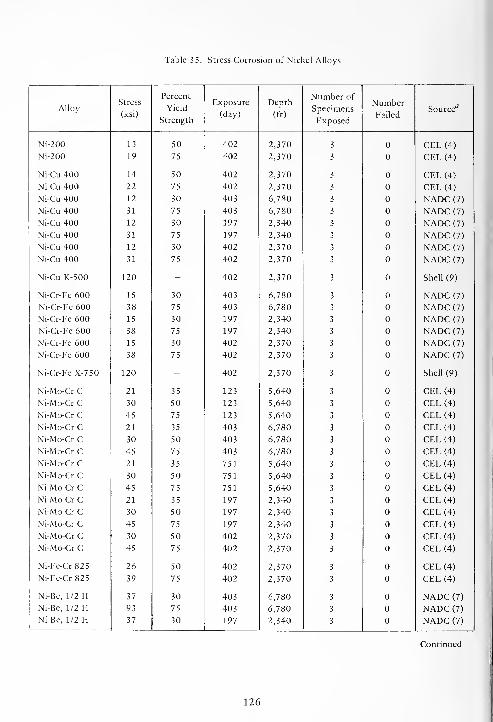
Table 35. Stress Corrosion of Nickel Alloys
AlloyStress
(ksi)
Percent
Yield
Strength
Exposure
(day)
Depth
(ft)
Number of
Specimens
Exposed
Number
FailedSource"
Ni-200 13 50 402 2,370 3 CEL (4)
Ni-200 19 75 402 2,370 3 CEL(4)
Ni-Cu 400 14 50 402 2,370 3 CEL (4)
Ni-Cu 400 22 75 402 2,370 3 CEL (4)
Ni-Cu 400 12 30 403 6,780 3 NADC (7)
Ni-Cu 400 31 75 403 6,780 3 NADC (7)
Ni-Cu 400 12 30 197 2,340 3 NADC (7)
Ni-Cu 400 31 75 197 2,340 3 NADC (7)
Ni-Cu 400 12 30 402 2,370 3 NADC (7)
Ni-Cu 400 31 75 402 2,370 3 NADC (7)
Ni-Cu K-500 120 - 402 2,370 3 Shell (9)
Ni-Cr-Fe 600 15 30 403 6,780 3 NADC (7)
Ni-Cr-Fe 600 38 75 403 6,780 3 NADC (7)
Ni-Cr-Fe 600 15 30 197 2,340 3 NADC (7)
Ni-Cr-Fe 600 38 75 197 2,340 3 NADC (7)
Ni-Cr-Fe 600 15 30 402 2,370 3 NADC (7)
Ni-Cr-Fe 600 38 75 402 2,370 3 NADC (7)
Ni-Cr-Fe X-750 120 - 402 2,370 3 Shell (9)
Ni-Mo-Cr C 21 35 123 5,640 3 CEL (4)
Ni-Mo-Cr C 30 50 123 5,640 3 CEL (4)
Ni-Mo-Cr C 45 75 123 5,640 3 CEL (4)
Ni-Mo-Cr C 21 35 403 6,780 3 CEL (4)
Ni-Mo-Cr C 30 50 403 6,780 3 CEL (4)
Ni-Mo-Cr C 45 75 403 6,780 3 CEL (4)
Ni-Mo-Cr C 21 35 751 5,640 3 CEL (4)
Ni-Mo-Cr C 30 50 751 5,640 3 CEL (4)
Ni-Mo-Cr C 45 75 751 5,640 3 CEL (4)
Ni-Mo-Cr C 21 35 197 2,340 3 CEL (4)
Ni-Mo-Cr C 30 50 197 2,340 3 CEL (4)
Ni-Mo-Cr C 45 75 197 2,340 3 CEL (4)
Ni-Mo-Cr C 30 50 402 2,370 3 CEL (4)
Ni-Mo-Cr C 45 75 402 2,370 3 CEL (4)
Ni-Fe-Cr825 26 50 402 2,370 3 CEL (4)
Ni-Fe-Cr 825 39 75 402 2,370 3 CEL (4)
Ni-Be, 1/2 H 37 30 403 6,780 3 NADC (7)
Ni-Be, 1/2 H 93 75 403 6,780 3 NADC (7)
Ni-Be, 1/2 H 37 30 197 2,340 3 NADC (7)
Continued
126

Table 35. Continued.
AlloyStress
(ksi)
Percent
Yield
Strength
Exposure
(day)
Depth
(ft)
Number of
Specimens
Exposed
Number
FailedSource 1*
Ni-Be, 1/2 HNi-Be, 1/2 HNi-Be, 1/2 H
Ni-Be, 1/2 HTNi-Be, 1/2 HTNi-Be, 1/2 HT
93
37
93
60
60
60
75
30
75
30
30
30
197
402
402
403
197
402
2,340
2,370
2,370
6,780
2,340*
2,370
3
3
3
3
3
3
NADC (7)
NADC (7)
NADC (7)
NADC (7)
NADC (7)
NADC (7)
aNumbers refer to references at end of report.
'Severe corrosion at sheared edges indicating possible susceptibility to stress corrosion cracking.
127

SECTION 5
STAINLESS STEELS
The corrosion resistance of stainless steels is
attributed to a very thin, stable oxide film on the
surface of the alloy which results from the alloying of
carbon steels with chromium. Chromium, being a
passive metal (corrosion resistant), imparts its
passivity to steel when alloyed with it in amounts of
12% or greater. These iron-chromium alloys are very
corrosion-resistant in oxidizing environments because
the passive film is maintained in most environments
when a sufficient amount of oxidizing agent or
oxygen is present to repair any breaks in the protec-
tive film.
The corrosion resistance of stainless steels is
further enhanced by the addition of nickel to the
iron-chromium alloys. This group of alloys is popu-
larly known as the 18-8 (18% chromium — 8% nickel)
stainless steels.
In general, oxidizing conditions favor passivity
(corrosion resistance), while reducing conditions
destroy it. Chloride ions are particularly agressive in
destroying this passivity.
Stainless steels usually corrode by pitting and
crevice corrosion in seawater. Pits begin by break-
down of the passive film at weak spots or at non-
homogeneities. The breakdown is followed by the
formation of an electrolytic cell, the anode of which
is a minute area of active metal and the cathode of
which is a considerable area of passive metal. The
large potential difference characteristic of this
"passive-active" cell accounts for considerable flow of
current with attendant rapid corrosion (pitting) at the
small anode.
Pitting is most likely to occur in the presence of
chloride ions (for example, seawater), combined with
such depolarizers as oxygen or oxidizing salts. Anoxidizing environment is usually necessary for pre-
servation of passivity with accompanying high
corrosion resistance; but, unfortunately, it is also a
favorable condition for pitting. The oxidizer can
often act as a depolarizer for passive-active cells that
were established by breakdown of passivity at a
specific point or area. The chloride ion in particular
can accomplish this breakdown.
Stainless steels can and do pit in aerated seawater
(near neutral chloride solution). Pitting is less pro-
nounced in rapidly moving seawater (aerated
solution) as compared with partially aerated, stagnant
seawater. The flow of seawater carries away corrosion
products which would otherwise accumulate at
crevices or cracks. It also insures uniform passivity
through free access of dissolved oxygen.
As discussed above, stainless steels generally cor-
rode in seawater by pitting and crevice corrosion;
therefore, "as much as 90 to 95% of the exposed
surface can be uncorroded. With such low percentages
of the total exposed area affected, corrosion
calculated from loss in weight as mils penetration per
year (mpy) can give a very misleading picture. The
mpy implies a uniform decrease in thickness, which,
for stainless steels, is not the case.
A manifestation of pitting corrosion, whose
presence and extent is often overlooked, is tunnel
corrosion. Tunnel corrosion is also classified by some
as edge, honeycomb, or underfilm corrosion. Tunnel
corrosion is insidious because of its nature and
because many times it is not apparent from the
outside surfaces of the object. It starts as a pit on the
surface or on an edge and propagates laterally
through the material, many times leaving thin films of
uncorroded metal on the exposed surfaces.
Another manifestation of localized attack in
stainless steels is oxygen concentration cell corrosion
in crevices (usually known as crevice corrosion). This
type of corrosion occurs underneath deposits of any
kind on the metal surface, underneath barnacles, and
at the faying surfaces of a joint. The area of stainless
steel that is shielded from the surrounding solution
becomes deficient in oxygen, thus creating a
difference in oxygen concentration between the
shielded and unshielded areas. An electrolytic cell is
created, with a difference of potential being
generated between the high and low oxygen concen-
tration areas (the low oxygen concentration area
becomes the anode of the cell).
Low weight losses and corrosion rates accompany
these manifestations of corrosion. Thus, the integrity
129
of a stainless steel structure can be jeopardized if
designed solely on the basis of corrosion rates calcu-
lated from weight losses rather than on the basis of
measured depths of pits, lengths of tunnel corrosion,
and depths of crevice corrosion. Pitting, tunneling,
and crevice corrosion, can and do penetrate stainless
steel rapidly, thus rendering it useless in short periods
of time.
Therefore, corrosion rates expressed as mpy
calculated from weight losses, maximum pit depths,
maximum lengths of tunnel corrosion, maximum
depths of crevice corrosion, and types of corrosion
are tabulated to provide an overall picture of the
corrosion of the stainless steels.
5.1. AISI 200 SERIES STAINLESS STEELS
The chemical compositions of the AISI 200 Series
stainless steels are given in Table 36, their corrosion
rates and types of corrosion in Table 37, their stress
corrosion behavior in Table 38, and the effect of
exposure on their mechanical properties in Table 39.
The AISI 200 Series stainless steels are 300 Series
stainless steels modified by substituting manganese
for about one-half of the nickel. This modification
does not adversely affect the corrosion resistance of
iron-chromium-nickel alloys in many environments.
5.1.1. Duration of Exposure
The AISI 201 and 202 alloys were attacked by
crevice and pitting types of corrosion both at the
surface and at depths in the seawater. There was a
tendency for both alloys to be more severely cor-
roded after longer periods of exposure both at the
surface and at depth. The bottom sediments were
about as corrosive as the seawater above them.
5.1.2. Effect of Depth
5.1.3. Effect of Concentration of Oxygen
The effect of changes in the concentration of
oxygen in seawater on the corrosion of both AISI
201 and 202 stainless steels was nonuniform. In
general, crevice and pitting corrosion were more rapid
and severe at the surface than at depth, but there was
no definite correlation between corrosion and oxygen
concentration.
As is well known, oxygen can and does play a
dual role in the corrosion of stainless steels in electro-
lytes (for example, seawater). An oxidizing environ-
ment (presence of oxygen or other oxidizers) is
necessary for maintaining the passivity of stainless
steels. However, this same oxidizing environment is
necessary to initiate and maintain pitting in stainless
steels. Oxygen often acts as the depolarizer for
passive-active cells created by the breakdown of
passivity at a specific point or area. The chloride ion
(present in abundance in seawater) is singularly
efficient in accomplishing this breakdown. Therefore,
this dual role of oxygen can be used to explain the
inconsistent and erratic corrosion behavior of stain-
less steels in seawater.
5.1.4. Stress Corrosion
AISI 201 stainless steel was exposed at the depths
and for the times shown in Table 38 when stressed at
values equivalent to 30 and 75% of its yield strength
to determine its susceptibility to stress corrosion.
AISI 201 stainless steel was not susceptible to stress
corrosion under the above conditions of test.
5.1.5. Mechanical Properties
The effects of exposure on the mechanical
properties of AISI 201 and 202 stainless steels are
given in Table 39. The mechanical properties were
not adversely affected.
The corrosion of AISI 201 was approximately the
same at the surface as at depth, while that of AISI
202 was less severe at depth than at the surface. How-ever, it was concluded that depth had no definite
influence on the corrosion of the AISI 200 Series
stainless steels.
5.2. AISI 300 SERIES STAINLESS STEELS
The chemical compositions of the AISI 300 Series
stainless steels are given in Table 40, their corrosion
rates and types of corrosion in Table 41, their stress
130
corrosion behavior in Table 42, and the effect of
exposure on their mechanical properties in Table 43.
The corrosion of the AISI 300 Series stainless
steels was very erratic and unpredictable. They were
attacked by crevice, pitting, and tunnel types of cor-
rosion, in varying degrees of severity ranging from
incipient to perforation of the thickness of the
specimens and tunnels extending laterally for a
distance of 11 inches (11,000 mils) through the
specimen. Comparing the intensities of these types of
localized corrosion with the corresponding corrosion
rates indicates no definite correlation between them.
Two alloys, AISI 317 and 329, were attacked
only by incipient crevice corrosion during exposures
at all three depths (surface, 2,500, and 6,000 feet) in
seawater for periods ranging from 366 days at the
surface to 1,064 days at the 6,000-foot depth.
Sensitization (heating for 1 hour at 1,200°F and
cooling in air) rendered AISI 304 and 316 stainless
steels more susceptible to corrosion than their
unsensitized counterparts.
5.2.1. Duration of Exposure
Examination of the data in Table 41 shows that
there is no definite or consistent correlation between
severity of corrosion or corrosion rates and duration
of exposure. For example, at the 6,000-foot depth in
seawater the intensities of pitting and tunnel cor-
rosion were greater after 403 days than after 1,064
days of exposure, the intensity of crevice corrosion
was greater after 1,064 days than after 403 days of
exposure, and the maximum corrosion rate was
greater after 1,064 days than after 403 days of
exposure.
5.2.2. Effect of Depth
The data in Table 41 show, in general, that the
intensities of crevice, pitting, and tunnel corrosion
were either about the same or greater at the surface
than at the depth. The corrosion rates are in agree-
ment with this conclusion in that those of most of
the alloys were greater at the surface than at depth.
Based on these data and the above statements, it is
concluded that depth in the ocean exerts no signifi-
cant influence on the corrosion of AISI 300 Series
stainless steels.
5.2.3. Effect of Concentration of Oxygen
There was no definite correlation between the
intensities of pitting, tunnel, and crevice corrosion of
the AISI 300 Series stainless steels and changes in the
concentration of oxygen in seawater after 1 year of
exposure. On the basis of corrosion rates for those
alloys which had definite weight losses, the rates
increased with increasing concentration of oxygen,
but not uniformly.
These data indicate that the corrosion of the AISI
300 Series stainless steels is not proportional to
changes in the concentration of oxygen in seawater.
The dual role oxygen plays in the corrosion of stain-
less steels in seawater, as discussed previously, also
applies here as an explanation for the erratic behavior
of AISI 300 Series stainless steels.
5.2.4. Stress Corrosion
Some of the AISI 300 Series stainless steels were
stressed at values ranging from 30 to 80% of their
respective yield strengths. They were exposed in the
seawater at depths of 2,500 and 6,000 feet for
various periods of time to determine their suscepti-
bility to stress corrosion cracking. These data are
given in Table 42.
None of the steels were susceptible to stress cor-
rosion under the conditions of these tests.
5.2.5. Mechanical Properties
The effects of exposure on the mechanical
properties of some of the 300 Series stainless steels
are given in Table 43.
In only two cases were the mechanical properties
adversely affected: (1) After 1,064 days of exposure
at the 6,000-foot depth, the tensile and yield
strengths and the elongation of AISI 304L were
reduced by about 30%. This is attributed to the per-
foration of the specimen by both crevice and pitting
corrosion, and edge and tunnel corrosion. (2) After
402 days of exposure at the 2,500-foot depth, the
tensile and yield strengths of welded, sensitized AISI
316 were reduced by 45%. These reductions are
attributed to the effects of welding.
131

5.3. AISI 400 SERIES STAINLESS STEELS
The chamical compositions of the AISI 400 Series
stainless steels are given in Table 44, their corrosion
rates and type of corrosion in Table 45, their stress
corrosion behavior in Table 46, and the effect of
exposure on their mechanical properties in Table 47.
The AISI 400 Series stainless steels are those
which nominally contain 11 to 27% chromium. The
400 Series stainless steels are further divided into
ferritic and martensitic steels. The ferritic steels are
nonhardenable by heat treatment; those in this
category in this program were AISI 405, 430, and
446. The martensitic steels are hardenable by heat
treatment, and the one in this category in this pro-
gram was AISI 410.
The corrosion of the AISI 400 Series stainless
steels was erratic and was characterized by the
localized types of corrosion (crevice, pitting, and
tunnel). The intensities of these types varied from
none to complete perforation of the thickness of the
specimens for the crevice and pitting types and tunnel
corrosion extending laterally the entire 12-inch
(12,000 mils) length of specimens. There was no
correlation between the intensities of these types of
localized corrosion and the corresponding corrosion
rates calculated from weight losses. The frequencies
and intensities of these types of corrosion were also
greater for the AISI 400 Series stainless steels than
for the AISI 300 Series stainless steels.
5.3.1. Duration of Exposure
The data in Table 45 show no correlation
between either intensities of the localized types of
corrosion or corrosion rates and duration of expo-
sure. Neither one decreased or increased continuously
with increasing duration of exposure.
5.3.2. Effect of Depth
Depth had no uniform or gradual effect on the
corrosion rates of the AISI 400 Series stainless steels,
although the rates were lower at depth than at the
surface. However, these corrosion rates did not
decrease with increasing depth, i.e., they were lower
at the 2,500-foot depth than at the 6,000-foot depth
for two of the four steels. The intensities of the
localized types of corrosion were either the same or
greater at the surface as at depth.
Depth had no definite influence on the corrosion
of the AISI 400 Series stainless steels.
5.3.3. Effect of Concentration of Oxygen
In general, the corrosion rates of the AISI 400
Series stainless steels were higher at the highest con-
centration of oxygen (at the surface) than at the
lower concentrations. However, the increases were
not proportional to the increase in the oxygen con-
centration except for AISI 410 after 1 year of
exposure. The intensities of the localized types of
corrosion were not influenced by changes in the
concentration of oxygen in the seawater.
In general, changes in the concentration of
oxygen in seawater did not exert a major influence on
the corrosion of the AISI 400 Series stainless steels.
5.3.4. Stress Corrosion
The AISI 400 Series stainless steels were stressed
at values ranging from 30 to 75% of their respective
yield strengths. They were exposed in seawater at the
2,500- and 6,000-foot depths for various periods of
time to determine their susceptibilities to stress cor-
rosion cracking. These data are given in Table 46.
None of the AISI 400 Series stainless steels were
susceptible to stress corrosion under the conditions of
these tests.
5.3.5. Mechanical Properties
The effects of exposure on the mechanical pro-
perties of the AISI 400 Series stainless steels are given
in Table 47.
In only two cases were the mechanical properties
seriously impaired: (1) After 403 days of exposure at
the 6,000-foot depth, the tensile and yield strengths
and the elongation of AISI 405 were seriously
reduced. (2) After 751 days of exposure at the
6,000-foot depth, the tensile and yield strengths and
the elongation of AISI 430 were completely
destroyed.
In all other exposures and for the other steels
there was no impairment of the mechanical pro-
perties.
132
5.3.6. Corrosion Products
The corrosion products taken from one of the
corrosion tunnels in AISI Type 430 stainless steel
were analyzed by X-ray diffraction, spectrographic
analysis, quantitative chemical analysis, and infra-red
spectrophotometry and were found to contain
amorphous ferric oxide (Fe 7 3*XH
2 0), Fe, Cr, Mn,
Si, trace of Ni, 1.41% chloride ion, 2.12% sulfate ion,
and a significant amount of phosphate ion.
5.4. PRECIPITATION-HARDENINGSTAINLESS STEEL
The chemical compositions of the precipitation-
hardening stainless steels are given in Table 48, their
corrosion rates and types of corrosion in Table 49,
their stress corrosion behavior in Tables 50 and 51,
and the effect of exposure on their mechanical
properties in Table 52.
The precipitation-hardening stainless steels differ
from the conventional stainless steels (AISI Series
200, 300, and 400) in that they can be hardened to
very high strength levels by heating the annealed
steels to temperatures in the 900 to 1,200°F range
and then cooling in air.
The corrosion of the precipitation-hardening
stainless steels was erratic and was of the crevice,
pitting, and tunnel types of localized corrosion with
some edge attack. There was no correlation between
the intensities of these types of localized corrosion
and the corresponding corrosion rates calculated from
weight losses. The frequencies and intensities of these
types of corrosion were greater for the precipitation-
hardening stainless steels than for the AISI 300 Series
stainless steels.
The 15-7AMV steels corroded at extremely rapid
rates by crevice, pitting, tunnel, and edge corrosion.
In many instances, large portions of the specimens
had been lost due to corrosion; in other cases tunnel
corrosion had extended laterally through the speci-
mens for distances of 1 1 or 12 inches within a year of
exposure. They were considerably more susceptible
to corrosion than were the other precipitation-
hardening stainless steels.
Alloy 17Cr-14Ni-Cu-Mo was nearly free of cor-
rosion after exposure for 366 days at the surface, 402
days at 2,500 feet, and 1,064 days at 6,000 feet.
There was one case of pitting to a depth of 3 mils
after 181 days of exposure at the surface. There was
incipient crevice corrosion at the surface and at depth
except for pitting to a depth of 3 mils after 1,064
days of exposure in the bottom sediment at the
6,000-foot depth.
5.4.1. Duration of Exposure
The data in Table 49 show that there was no
correlation between the intensities of the localized
types of corrosion and duration of exposure. Also,
there was no correlation between corrosion rates
calculated from weight losses and duration of
exposure except for the 15-7AMV steels for which
the corrosion rates increased with increasing time of
exposure.
5.4.2. Effect of Depth
In general, depth had no effect on the corrosion
of the precipitation-hardening stainless steels.
5.4.3. Effect of Concentration of Oxygen
Changes in the concentration of oxygen in sea-
water exerted no definite or major influence on the
corrosion behavior of the precipitation-hardening
stainless steels.
5.4.4. Effect of Welding
A 3-inch-diameter circular, unrelieved weld was
made in the center of the 6 x 12-inch specimens of
some of the alloys to impose residual stresses in the
specimens. Others had a 6-inch-long transverse,
unrelieved butt weld across the center of the
6 x 12-inch specimens. These welds were to deter-
mine whether welding affected the corrosion behavior
and stress corrosion susceptibilities of the alloys.
Welding did not affect the corrosion behavior of
the precipitation-hardening stainless steels.
The effects of residual stresses imposed by
welding will be discussed under 5.4.5.
5.4.5. Stress Corrosion
The precipitation-hardening stainless steels were
stressed at values ranging from 35 to 85% of their
133
respective yield strengths. They were exposed in sea-
water at the surface, 2,500-, and 6,000-foot depths
for various periods of time to determine their sus-
ceptibilities to stress corrosion. Their data are given in
Table 50. A 3-inch-diameter circular, unrelieved weld
was made in the center of the 6 x 12-inch specimens
of some alloys to impose residual stresses in them.
Transverse, unrelieved butt welds were made in other
specimens for the purpose of simulating stresses
induced during construction or fabrication. These
residual stresses were multiaxial rather than uniaxial
as was the case with the specimens with calculated
stresses. In addition, values of these residual stresses
were indeterminable. These specimens were exposed
in seawater under the same conditions as those above.
Their data are given in Table 51.
Alloy AIS1 630,H925 with a transverse butt weld
did not fail by stress corrosion when stressed to 75%
of its yield strength either at the surface or at depth.
However, it did fail due to the unrelieved stresses
imposed by the circular weld after 403 days of
exposure at the 6,000-foot depth. The crack pro-
pagated across the weld bead.
Specimens of transverse, butt-welded AISI
631,TH1050 failed when stressed to 50% of its yield
strength and exposed both at the surface and at
depth. Specimens with circular welds also failed when
exposed at the surface and at depth. At the surface
the cracks extended radially from a point inside the
circle to the circular weld bead. At depth the crack
extended across and around the outside edge of the
weld bead.
Specimens of transverse, butt-welded AISI
631,RH1050 failed when stressed to 75% of its yield
strength and exposed at the 2,500-foot depth. Speci-
mens with circular weld beads also failed when
exposed at depth. The cracks originated at the out-
side edge of the weld beads and propagated circum-
ferentially in both directions either at the edge of the
weld bead or in the heat-affected zone.
Specimens of alloy AISI 632,RH100 with a trans-
verse butt weld did not fail by stress corrosion when
stressed to 75% of its yield strength and exposed
either at the surface or at depth. However, a specimen
with a circular weld failed during 402 days of expo-
sure at the 2,500-foot depth. The origin of the crack
was on the outside edge of the weld bead, and it
propagated circumferentially in both directions in the
heat-affected zone.
Alloys AISI 634,CRT; AISI 635; ASTMXM16,H950 and H1050; AL362.H950 and H1050;
and alloy 18Cr-14Mn-0.5N were not susceptible to
stress corrosion under the conditions of these tests.
Alloy PH14-8Mo,SRH950 with a transverse butt
weld failed by stress corrosion cracking when stressed
to 50% of its yield strength and exposed at depth.
Specimens of 15-7AMV in the A, RH1150, and
RH950 tempers failed by stress corrosion cracking
when stressed at 35, 50, and 75% of their respective
yield strengths and exposed at depth. Alloy
15-7AMV,RH1 150 failed when exposed at depth due
to the stresses imposed by it being squeezed between
insulators such that it was slightly bowed. Alloys of
15-7AMV,RH1150 and RH950 failed by stress cor-
rosion when exposed at depth; the cracks originated
at unreamed, drilled holes in the specimens.
5.4.6. Mechanical Properties
The effects of exposure on the mechanical
properties of the precipitating-hardening stainless
steels are given in Table 52. Generally, the mechanical
properties of the precipitation-hardening stainless
steels were adversely affected by exposure in seawater
both at the surface and at depth.
5.5. MISCELLANEOUS STAINLESS STEELS
Included in this category are the case and
specialty stainless steels which could not be included
in the other classifications. Their higher nickel con-
tents and the addition of molybdenum are to increase
the range of protection of their passive films and to
increase their r< istance to pitting corrosion. Because
these passive films are so much more resistant to
destruction, any corrosion '-• localized in the form of
crevice and pitting.
The chemical compositions of the miscellaneous
stainless steels are given in Table 53, their corrosion
rates and types of corrosion in Table 54, their stress
corrosion behavior in Table 55, and the effect of
exposure on their mechanical properties in Table 56.
These alloys were considerably more resistant to
corrosion than the other alloys. There were two cases
of crevice corrosion at depth of alloy 20Cb, with the
deepest attack being 102 mils. There were also two
134
cases each of crevice and pitting attack during surface
exposure; 21 mils maximum for crevice corrosion,
and 24 mils maximum for pitting corrosion.
Alloy 20Cb-3, a modified version of 20Cb (4%
higher nickel content), was more resistant to cor-
rosion by seawater and the bottom sediments than
20Cb. There was only one case of crevice corrosion
(40 mils deep) at depth.
The corrosion of two cast versions of 20Cb,
Ni-Cr-Cu-Mo numbers 1 and 2, was very similar to
that of the 20Cb. There were isolated cases of crevice
corrosion, the maximum depth of attack being 27
mils.
There was only incipient crevice corrosion on cast
alloy Ni-Cr-Mo during exposure at the surface and at
depth.
Cast alloy Ni-Cr-Mo-Si was not susceptible to cor-
rosion by seawater during exposure either at the sur-
face or at depth.
Cast alloy RL-35-100 was attacked by general and
uniform types rather than by the localized types of
corrosion. The corrosion rates were rather low, the
maximum being 0.7 mil per year after 3 years of
exposure at the 6,000-foot depth.
The corrosion behavior of these alloys was not
affected by duration of exposure, depth of exposure,
or changes in the concentration of oxygen in sea-
water.
As shown in Table 55, alloy 20Cb was not sus-
ceptible to stress corrosion in seawater at depth.
The effects of exposure in seawater on the
mechanical properties of alloy 20Cb are given in
Table 56. The mechanical properties were not
affected.
135

Table 36. Chemical Compositions of 200 Series stainless Steels, Percent by Weight
Alloy C Mn P S Si Ni Cr Fe" c bSource
AISI 201 0.08 6.8 _ — - 4.0 17.1 R INCO(3)
AISI 201 0.14 7.0 - 0.009 - 4.5 16.5 R NADC (7)
AISI 202 0.09 7.6 - - - 4.5 17.8 R INCO(3)
AISI 202 0.13 7.9 — 0.007 — 5.2 17.0 R NADC (7)
aR = remainder.
Numbers refer to references at end of report.
Table 37. Corrosion Rates and Types of Corrosion of 200 Series Stainless Steels
Alloy EnvironmentExposure Depth
Co rrosion
c cSourceMaximum Crevice
(day) (ft) Rate
(mpy)Pit Depth
(mils)
Depth*
(mils)
Type .
AISI 201 W 123 5,640 <0.1 I I-C INCO (3)
AISI 201 W 123 5,640 <0.1 NC NADC (7)
AISI 201 S 123 5,640 <0.1 NC INCO (3)
AISI 201 W 403 6,780 <0.1 I I-C INCO (3)
AISI 201
AISI 201^W 403 6,780 - - s S-C NADC (7)
W 403 6,780 - - - WB (NC) NADC (7)
AISI 201 s 403 6,780 <0.1 2 C INCO (3)
AISI 201 w 751 5,640 <0.1 I I-C INCO (3)
AISI 201 w 751 5,640 - - S S-C NADC (7)
AISI 201 s 751 5,640 <0.1 NC INCO (3)
AISI 201 w 1,064 5,300 <0.1 I I-C INCO (3)
AISI 201 s 1,064 5,300 0.5 50 1 I-CiP (PR) INCO (3)
AISI 201 w 197 2,340 <0.1 4 C INCO (3)
AISI 201 w 197 2,340 - - S S-C NADC (7)AISI 201 s 197 2,340 <0.1 3 C INCO (3)
AISI 201 w 402 2,370 <0.1 1 c INCO (3)
AISI 201 w 402 2,370 - - S S-C; WB (S-C) NADC (7)AISI 201 s 402 2,370 <0.1 2 C INCO (3)AISI 201 w 182 5 <0.1 I I-C INCO (3)AISI 201 w 366 5 0.6 S-E INCO (3)
AISI 202 w 123 5,640 <0.1 NC INCO (3)AISI 202 w 123 5,640 <0.1 - - NC NADC (7)AISI 202 s 123 5,640 <0.1 NC INCO (3)AISI 202 w 403 6,780 <0.1 I I-C INCO (3)AISI 202 s 403 6,780 <0.1 I I-C INCO (3)AISI 202 w 751 5,640 <0.1 I I-C INCO (3)AISI 202 s 751 5,640 <0.1 I I-C INCO (3)
136
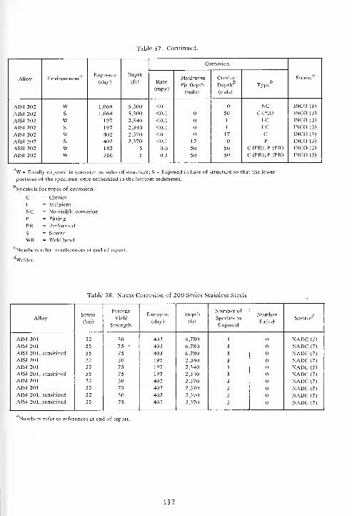
Table 37. Continued.
Alloy r- J1Environment
Exposure
(day)
Depth
(ft)
Corrosion
SourceRate
(mpy)
MaximumPit Depth
(mils)
Crevice
Depthfo
(mils)
Type
AISI 202
AISI 202
AISI 202
AISI 202
AISI 202
AISI 202
AISI 202
AISI 202
WS
WS
Ws
ww
1,064
1,064
197
197
402
402
182
366
5,300
5,300
2,340
2,340
2,370
2,370
5
5
<0.1
<0.1
<0.1
<0.1
<0.1
<0.1
0.6
0.5
17
50
50
50
I
I
17
50
50
NCC(PR)
I-C
I-C
CP
C(PR);P (PR)
C (PR);P (PR)
INCO (3)
INCO (3)
INCO (3)
INCO (3)
INCO (3)
INCO (3)
INCO (3)
INCO (3)
W = Totally exposed in seawater on sides of structure; S = Exposed in base of struct
portions of the specimen were embedded in the bottom sediments.
Symbols for types of corrosion:
c = Crevice
I = Incipient
NC = No visible corrosion
P = Pitting
PR = Perforated
S = Severe
WB = Weld bead
"Numbers refer to references at end of report.
^Welded.
Table 38. Stress Corrosion of 200 Series Stainless Steels
AlloyStress
(ksi)
Percent
Yield
Strength
Exposure
(day)
Depth
(ft)
Number of
Specimens
Exposed
NumberFailed
Source
AISI 201
AISI 201
AISI 201, sensitized
AISI 201
AISI 201
AISI 201, sensitized
AISI 201
AISI 201
AISI 201, sensitized
AISI 201, sensitized
22
55
55
22
55
55
22
55
22
55
30
75 •
75
30
75
75
30
75
30
75
403
403
403
197
197
197
402
402
402
402
6,780
6,780
6,780
2,340
2,340
2,340
2,370
2,370
2,370
2,370
3
3
3
3
3
3
3
3
3
3
NADC (7)
NADC (7)
NADC (7)
NADC (7)
NADC (7)
NADC (7)
NADC (7)
NADC (7)
NADC (7)
NADC (7)
Numbers refer to references at end of report.
137

t^ r-> t^ t^ c^ r-* r-- r-~
U <J u u u u O U3 Q Q Q Q Q Q Q QO <<<<<< < <C/l z z z z z z z z
SOC \o t 00 w Ov m o
.
C J3U
+ + 1r^> (si m+ + +
1
aSOCo03 c ^^
oo oo oo oo oo in|
Si 5? -* -vt- * * *6
bo
J3c
J3
O O 't * N * O <H
60,-h 1 rr, rn ro
TC Uu
-T3 _V
5 '-'
>6~ t— i>- r— r— t—
-
i i
uDO
J= C m cnI O r^ no 00 no ooboCV U + + III + i
t/3
rt
C C .O O O O O O NO noOJ
:§>.§,(N N N N N o o
H t-H r-{ T-t t-H t-H ^H i—
1
ow
, o o o o o o o otJ- * rt- t-~ t-~ r-~ * -sj-
C
0- .^
3
NO no r*"i rn m m NO NO
in in (S r\l tsi <S in in
J
IS m .-h t~~ (N (v) (s m t-h
<N in On O O O (M inB. T3 H N H i- i- + <-i r^X ^
[d
a
C
eco £ £ £ £ £ £ £ £
cu
T3<U
-a .H
o -
S!
"aj C
o £ &!
< o o o © o o(vl (NO ON N N N N N (M (N
(/) 1/1 t/1 (/I 71 1/1 on on
<<<<<< < <
£ £
138
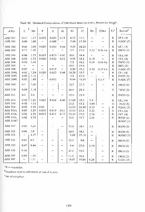
Table 40. Chemical Compositions of 300 Series Stainless Steels, Percent by Weight
Alloy C Mn P S Si Ni Cr Mo Other Fe" Source
AISI 301 0.11 1.17 0.025 0.021 0.34 6.73 17.4 — — R CEL (4)
AISI 301 0.08 1.00 - 0.008 - 7.50 17.50 - - R NADC (7)
AISI 302 0.06 1.05 0.020 0.013 0.60 9.33 18.21 - - R CEL (4)
AISI 302 0.11 1.36 - - - 9.9 17.3 0.12 0.26 Cu R INCO(3)
AISI 304 0.06 1.73 0.024 0.013 0.43 10.0 18.8 - - R CEL (4)
AISI 304 0.05 1.73 0.020 0.012 0.52 9.55 18.2 0.18 - R CEL (4)
AISI 304 0.06 1.46 - - - 9.5 18.2 0.34 0.16 Cu R INCO (3)
AISI 304 - - - - - 10.0 19.0 - - R MEL (5)
AISI 304 0.07 - - 0.019 - 8.90 18.2 0.30 0.19 Cu R NADC (7)
AISI 304L 0.03 1.24 0.028 0.023 0.68 10.20 18.7 - - R CEL (4)
AISI 304L 0.02 1.45 - - - 9.5 17.9 - - R INCO (3)
AISI 304L 0.03 1.80 - 0.015 - 10.00 18.90 - 0.2 V R NADC (7)
AISI 309 0.1 1.60 - - - 12.7 23.3 - - R INCO (3)
AISI 310 0.04 1.78 - - - 20.9 25.3 - - R INCO (3)
AISI 311 0.2 2.0 - - - 19.0 25.0 - - R INCO (3)
AISI 316 0.06 1.61 0.021 0.016 0.40 13.60 18.3 2.41 - R CEL (4)
AISI 316 0.05 1.73 - - - 13.2 17.2 2.60 - R INCO (3)
AISI 316 0.05 1.40 0.01 - - 12.90 16.40 2.15 - R NADC (7)
AISI 316L 0.03 1.29 0.015 0.019 0.51 13.10 17.5 2.32 - R CEL (4)
AISI 316L 0.02 1.31 0.013 0.015 0.47 13.70 17.9 2.76 - R CEL (4)
AISI 316L 0.02 1.78 - - - 13.6 17.7 2.15 - R INCO (3)
AISI 316LCNADC (7)
AISI 317 0.05 1.61 - - - 13.6 18.7 3.3 - R INCO (3)
AISI 321 0.06 2.0 - - - 10.5 18.5 - - R INCO (3)
AISI 321 - 1.37 - - - 9.85 17.12 - - R NADC (7)
AISI 325 0.03 0.7 - - - 23.5 9.0 - - R INCO (3)
AISI 329 0.07 0.46 - - - 4.4 27.0 1.40 - R INCO (3)
AISI 330 0.20 - - - - 34.5 15.0 - - R INCO (3)
AISI 347 0.04 1.19 - - - 11.3 18.1 - - R INCO (3)
AISI 347 — 1.77 — — — 10.97 18.00 0.24 - R NADC (7)
R = remainder.
Numbers refer to references at end of report.
No values given.
139

t^
u St- u -t * * rt- ~t -1- * t*- * •* •* Tj- s s trj-^^-^^^^-^^- •^ rhjO jO vro'-;o";"J CJ-1 <J J U l-| U JW7U7M7W7W 8^
7 bJ
3oco
J Q<J hJ J -J _) -1 J -J J J J J J J
u bJ LO w u UJ fccl w w UJ W bJ W bJ uU Z o U u u u U U U u u U U u u
OS 0i OS tti OS oS o 2"Ha H H Oh 8j P_j
Oh (X Oh H H 2 erf o-
UJto
uC/3
v"JCO
Oh
H— CLl Oh
HOh
;T;P
(SL-C; SL-C; T;P(P
PjI o-
H ciq
0h "-^
""^ OhOh •-
co *~ co
U W
U u u bJ W WCO
U
_c
E g1
3 U ^ O O o o o O o o o o o o o o o 00000c |J| o o o o o O m o o o o in O Oo IN
|
t~ -t o o in o IT, CM Th in in N t-h in1
1 1 11
°-'trt ?< *u E t-H fM * "O o T-H VO r-i l-H N fN (S T-H T-H VO
^ 5
u3H
OJ -ou J3 -^
i. "-1 EJ J J m m O © o O -1 -1 o o o o o i-lOi-JO00_co_rt O _CO CO CO t—
'
cm CO CO in CO CO t-h CM "™ cm
U Q —
E js
ximuDept
nils)
o o O co co co CO CO co O O ro CO CO CO CO OOOOOOOOO O OO o o o o O O o o o ort *j O£ £
_co tH t-~ st- \£J f. o xl- O r^ m in XO 0\ co r- r*r-tr*r*^lr<r-<.r*.rH t-H iH
o o o t-H T-H T-H i-h o -H O O O O rt CM t-h OOOOOOOOO O OV vvvvvvvvv V V
_c o o o o o o o o o o o o O >n in in OOOOOOOOOs. 3
* + -t 00 oo * <t o o <* * t-> I> 't'tt'tMOOOOM't * ThVO VO o r-> r-- vo xO ro m m m m CO o^o^ovor^t^p^r^xo ^o \o
Q win in in VO \o in m in in (S <s M (N inininin^ONO^O^Oin in in
<u
m m co * * t-- r^ rs CXI t-H oo oo COCOCOCOCOCOCOCOt-Hs S CM CM CM o O m \o XO 0\ 0\ o O 00 o\ 00 CMCMCMCMOOOOm in inO pi
a. -ax ^
1-1 1-1 t-l <fr * r- f» q 9. ^ T-H 't * t-H co in T-Hrtrt^HTl-tTj-tTj-TH-t-. l-« r~T-H ^H
w
c
Ec £ £ CO s: co ^ CO £ CO ^ CO ^ CO ^ £ £ ^^COCO^^COCO^ ^ CO
cw
>N NINNNNNNNN CM <S_o o O o o o o O o o o O o o o o o OOOOOOOOO O O<
co CO co (V. co co m CO m m ""> rr> CO CO CO CO COCOCOCOCOCOCOCOCO CO CO
I/) 0/: CO CO CO CO CO VI CO CO CO CO CO CO CO CO cococococococococo CO CO
< < < < < < < < < < < < < < <i < <<<<<<<<< < <
140

uuu -h rJ-^-'Tj-'^TJ-^^T)-^-- ^ •* * •* — y> •* ^ •* u
D<Z
-1- •~* •&h* O O O O ";o"o";o"o o":^
CEL( INCO CEL( INCO CEL
( c ' o ^o CJ O u J u HcjHsjHcjHsj u H H u -J u H00 z z 2 a z U — U — U — U —
7 a w_ u u Z
CJ - u
HH .- H0- ^C H PC ^ t— CJOk pi CL, 0- Z Ha eu Ok ^ CU
u u OkCU o HCjHcjug^
Ok
~ Ok^
.- ... Ok
0k
CJ oa jCfl
V 2f-
— z £" U W ^ 1-1 •5 — ft.
Ok 2 " ^2 CJ OkOk w oi e- hucj
o
cfl
.c
E £>
2 u •— o o o o o o o o o o oc E J J3 t^ in O m o o in o oo
11
1
rgI
q | | Ov j1* "1 **
| | IP.1 |
1
v°-"3
s 1 -<" S© T^ <N
ou
OJ -a° -c 1?
revept mil _ o o £ - O__00_m_
1Or-~ - E E O „ i-K o o o -
1
o _ o
U Q --
E £E ?2 o o o o OOOOOO^m o o o o o o o o o o1 °'E
u-> 10 in ,-k — in in(S
1
rsl
ss"^^
£J:
o o O o o OOOOOOOO O o o o o ^ o o o o1o o o
V V V V V V V V V V V V V V V V V V V V
J3 o o o a o OOOOOOmm in in in o o o o o o o o o o oD. p«J IS.
<* o o -t- «* >*• •*• t~- r-- r-~ 1-^ * Tj- rj- -K- rj- 00 X X 00 co **\0 m m m m rrt rr, m m m m so so so so so h~ r~ t-~ t~- r^ so
Q in in in r-1 <S N N N M N N m m « m m so SO so SO so in
3 -> rt -+ * t^. t~ r^r*-cN<N(NrN*-<T-H so oo oo
O rt- in so
qON o OsONOOOOOOOO SO OS 00 N ts! (S N N O o
-1-o o O in
n. -ay, -^
W
c
Ec Cfl ;» Cfl £ =£ O0Cflr>:»CflCA;S;» £ £ £ S ;S ES Cfl Cfl =5 =S •5 Cfl Cfl =S
c
csi csi rsl CM (S NNNNNNNN N N N * * •* * <*• -d- -+ -i- Tl- •* tJ-o o S O o OOOOOOOO o o o o o o o o o o ~ S o om ro
<en en Cfl Cfl cfl OOCflCflCflCflcncflCfl oo co cfl Cfl Cfl 00 Cfl Cfl Cfl Cfl Cfl Cfl 00 Cfl
< < < < < <<<<<<:<<: < < < <<<<<< < < < < <
141

_ ^^--
r-> '*""" ^^ t^ro ^^/-Nf^^ffii^^
3oCO
°2^ *
- UINCO( MEL
(3
NADC
CEL
(4
INCO
(
CEL
(4
INCO(NADC
CEL
(4
INCO( CEL
(4
INCO(NADC
CEL
(4
INCO( CEL
(4
INCO
(CUz MEL
(5
CEL
(4
CEL
(4
INC0( INC0(
a. °r H UH 5 £
CO H w f;* oi ^ HH ^
~c -^ cc H So. ? H- H £
W cu .. ft. ua. U "z £
ft.
ft.
u - u (i « i £ ,j u v w.
"- ^C U ft.w
... — to U I-C
;P
(PR CS-T;W
a,
Uu £ w w u u J
ft, " CO
CO a. £ ° u
o W ; u a.
U " yCO U
.c
E g>
3 u — o o o o o o o o oc E j « ©in O o in © 00 rHo
11
1^
11 1 "1 1
°^ 1 IP. 1©_ 1 1 N | in
1
1 tH rH 1 1
'5! ^ "5 £ fN™j c -^s 5
oU
3
u -a° -C ^>S,s O m rr> rf m | o O ^h I _J — O m
|
O * © © m rn m CO © C^
u a —rn t— <S ! fS in rH 'CO CM \0 © ro in m
E -c
o O m o o o o © © O O O , O O O in * m (N O O Oa Q
'eCO W 1 H
| ~1
T-l * vO *M (N
ss v
_.1J >N
rtEl-
rH VO —1 rH ^H O rH rH m rH rH rH -*• rH rH iH 00 m * \o t- m r^ oo
O i-H o o O rH | O © O O | © © o © 1 O O -H rH © o o o o oV V V V V V V V V V V
o o o o ©ooooooo© © o © o O O in in in in m in © ©* * * o OOOOO**** * r-- r-- t~~ r^ r^ * *Q ~ XO vO \0 m mrrimr^rnmrnmr^ •o vq
in in in in l/1U">ii->i/li/"><S<MfMr>J N N N N <N (N
U3 C- rH * -^1- -^- -=1- -=d- ^J- r— tr-~ r~- i>- t~~ rs in rN N N H ri vo \0 O 00 w wO rt
a. -ox -—w
m vo NOsO\0^0\00\0\0\0\ o\ o o © O O 00 00 \0 CO * 03 N Nt-» r~- r-« O OOOOOrHrHrHrH -H * * * -* T*- rt vH
a
OJ
Eco
5- £ CO -^ ^^Scoco^^^co CO g: £ g: CO CO ^ ^ £ ^ £ 5- 3: co
c
* * * * ********* * * * * * * * * * * * * * *o o © o o ©ooooooo© o © © o o © o © O o o o © o<
m m m ro H-,mrnmmrr,m<N->m m m co m m m m m m m m m rr> mco to CO CO cococococococococo co co co co CO CO CO CO CO co co co co co
< < < < <<<<<<<<< < < < < < < < < < < < < < <
142

3OCO
O^OOOO^OO^OOqOOOzgzzzz|zz|zzgzzz CEL
(4)
INCO(3) CEL
(4)
INC0(3)CEL
(4)
INC0(3)
NADC
(7)
CEL
(4)
INC0(3)CEL
(4)
INC0(3)
co
8
ou
-a
n.C(PR)
S-C;S-T;WB(NC)c
C(PR);P(PR) C(PR) C(PR);P(PR)
S-C;
S-T
C(PR);P(PR) C(PR) S-C I-C C(PR)
S-C;
S-T;
WB
(NC)
C C(PR);P(PR) C(PR);P(PR) SL-C;T NCSL-C;T
NC
C;
E;P(PR);T
I-C
S-C;
S-T;
WB
(NC)
C;E;T C P(PR);T NC
Maximum
Tunnel
Length
(mils)
o o o o o1 1 1 1 1 1 1 1 1 1 1 1 1 1 1 1
N1 1
« | IP.
I
o|
Crevice
Depth
fo
(mils) O|
fM O O O |00 |_0 it-^OO J O i—1 O (N __ 1 0\(vlOOCO CO rt 1 <N
Maximum
Pit
Depth
(mils)
ooooooo oo ooo OOOOU-.0 OOmO
t^ <3" iri <N1 -tf- (N^O r-irn -^ r-n eg <N^--I^H^H^ rt^mr-id
I o d d dId d loo Io^^h
V VOOOOOO
| OOOOV V V V V V V
a. PQ
00000000000000u->lr>000000Tt-T|-OOO-+*-t-Tt-t^r^I-^ OOOOOOOOOOO^O^O^iflWViiAViNNNINNM
Exposure
(day)
OOOu^u-txOMD^OCNavOOOOO'O (S(S(N<NOOOOO>i-iu-i
C
Ecp
c
££co£cn££cog:g:cog:£co£:g: ^^coco^^^coco^^:
<OOOOOOOOOOOOOOOO OOOOOOOOOOO
cococococococococococo
143

^ ^^r*. r~ r~
rr» rr> m* + U
P<z
<t *J- U $Q j< wZ U
"* U
<z
•4- Tt —
'
* ^t
3OC/3 U
cuZ wu
cuz w
u
Ouz
ouz
Ouz wu
Ou2
Wu
ouz^8 O
uz wuWu
INCO INCO INCO
f- j H
0h Oh 22 ^^. H C3i
Oh H CL H 5 H Oh-d o« HQ_
H uz
Oh V JC/3
5 Oh H ^ ^ u u 5, u OS g H CJ i" v 0hOhOh
Oh u u uz z --.>n U W Oh
Oh
2a.
u C/3 Oh
OhC/3
N< w Oh Oh
W
2 *
—
V X w s0- U Ch
Ju C/3 O
_c
£ g>3 t ^ o o C c; o O o o o o
c E -J 3 o s C 3 O o o o -o o
1©_
i |
3|
cc1 | 1 q I |
o1
*1
|1
1 1
~ sf m" m -<" -H ^s 5
u3H
OJ -o° J= 1?£ a.
~ in o in _ 1 O o ool_-
1 2 ^^ O ^^|
o ^^ o _ O o in o o __
v- " tU Q —
rh
E -C
ximuDept
"nils)
O o in o in o O o,o o m o o o r^ o o m m o o o
1 1 10\
ss"^
02 S\o i-i CS l-H l-H C-l (S rH ^H l-H Th ^H rs! H r^ h in O t-H .-H >-H rt
o o o O 1 o o o o 1 o o O o1 o s O O O ,-H O o o o
V V V V V V V V V V
o o 3 o 3 o o o o o o o 3 o O o o in in m m in o o oo_ 3 * -1- 3 o O o o -t -t- <* + •+ r^ r^ r^ I-- t~H «* *• oo
VO o m m cr> m m m m m m pn m C«1 rn rri m NO nC nQ w
"" in in in m in in ts (S (N (N fS (S O) ts tS N in in so
u3 -^ -t ^t- <t rh •* r-- r~ t- ^ r- <s ts N (M NO X Os >* o o o vO no C\ OS Os 0\ On O o o O O oo oo NO On -t- N N OO rt
a. -ar-» c^ q q q q q l-H -I rt >-H >-l -t- * -+ -1- <* t-H hH rr> m in rt H +
w
a
c
Ec C/3 C/3 £ £ ES C/3 C/3 Eg: =S E& C/3 C/3 E£ £ E* C/3 C/3 =5 E5 =s hS s£ E? C/3 £
w
-J J J J j J -J J J J -J -J j J J J J -1 J J hJ -J>, Tj" -t + -t- + -t -t- ^J- •>* * <* -t -t Tj" -1- •* * * •+ + -1- •+ ON On Ono o o o c o o o o o o o O c c o O o o o o O o O O Om m m m m<
C/3 C/3 C/3 X C/3 X C/3 C/3 X c/3 c/3 X C/3 X X C/3 C/3 C/3 C/3 C/3 X ;/3 C/3 C/3 C/3
< < < < < < < < < < < < < < < < < < < < < < < < <
144
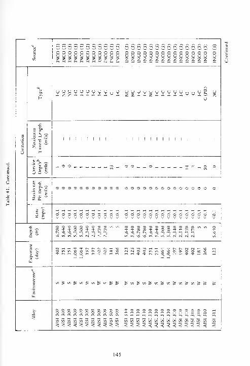
V
OC/3
ouz
pniw-,roiN-,mm"-,rommm mmfOfnmrnmfriffiPnrrirftrfirfi
oooooooooooCJUOUUOUUUUUZZZZZZZZZZZooooooooooooooUUUUUUUUUUUUUCJzzzzzzzzzzzzzz
o
u
It
Q, UOOOUUUUUyOu
UZ
Maximum
Tunnel
Length
(mils)1 1 1 1 1 1 1 1 1 1 1 1 [ 1 1 1 1 1 1 1 1 1 1 1 1 1
Crevice
Depth''(mils) — 00_____- „'-n_, 00„__0_______-3-(N_0 o
Maximum
Pit
Depth
(mils)
ooooooooooo oooooooooooooo o
u 1^
05 -Sooooooooooovvvvvvvvvvv oooooooooooooovvvvvvvvvvvvvv o
V
a- 3000000000"->"->oo'd-'d-OOT)-Tl-t^t-~.
OOOOOOOOOOOOu-im o*•OiriinirtirtfSiNr-ir-i miA^Om^tfiifttSNlNN
a. -aX —
'
w
Oinu->0^00\0©000 rM(NOO<^"->^0*O0\O\OO00v0 IN
c
E
">
tr>^(S)^tS)^iri^<si^^ ^C/5^tA)^:c/5^C/5^:t/3^C/)^^ £
<
OvOOOO\OnC^C^OnOnC\ooooooooooo OOOOOOOOOOOOOOr^m^mr^rr.ro^mr^mmro^ r«
C/3C/3C«C/3C/3C/3C/3C/2C/)C/3C/3 C/3</>t/i(/)(/)C/lC/5C/3C/3C/3t/)t/it/}[/5 C/3<<<<<<<<<<< <<<<<<<<<<<<<< <
145
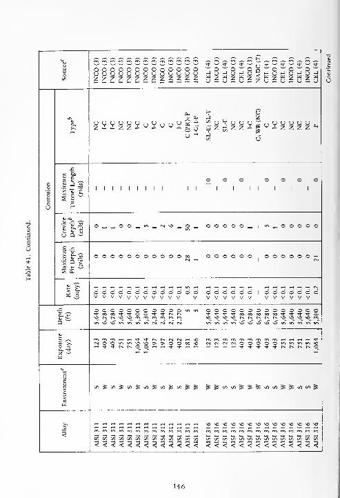
fD n rft ro my m m m cri rn f"> *^ * ~~- * '-' <*•
UQ<Z
* ^ * —- Tf ^ Tt-
3OCO
oooooooooooo o ^8 J° J O *•' -: ~ ~u H u H u duuuuuuuouuuu u UZZZZZZZZzZZZ z u a u a u z U a u a u a u„„_,„„--„„---
H uCLi J y
u
ziizz- u - uu -£uo
t« U
jCO
* u uJ z zCO
V 03
u
U u u u u u .I z z z z ^
JS
| % O O 000a E J 3
11 1 1 1 1 1 1 1 1 1 1
1 1 | 1 11
1
l
El « E
s s
U H
«j -oU JS o> s.| O„__OO„_u->_<nn0„O _ 000 _,
1
m _S u tU Q «-'
E j=
ximuDept
mils)
OOOOOOOOOOO00 000 O O O O O O ^H(N ""
1N
s s
^^
oooooooooooo o 0001OOOOOOVVVVvVVVVVV V V V V V V V V V V V V V
J2 OOOOOOOOOOOir> 1/1 000 OOOOOOa. J *oooO'*T|-oOTt-'*-r-i> * * <* •* 00 on CO on 00 * * <* **
NOt^r^NONOmmrncrimr*-! no no O tr-
U-> IT, \0 no no no
r-» no no \o no "->
NO ui wi in in inm>0>Oini«ininNNNN
mmm'rHrH^-^t^t^dCSi-H no m m m rH ,H rt ,-H ^« ^ CNOOu-iu-inOnoOnOn.0000 ^o <N rj N N O O in in m tn noi-l**r-«r>-0©»-li-l^^-«H m rt -H T)- & <+ ^- tJ- r- t~- t^ t^ O
W
a
c
£co
oo^co^co^co^co^co^ S: £ £ CO CO ^ £ 5: co CO ^ ^ CO CO ^
>cw
_o\o no no no no •0 NO MD NO NO NO NO NO NO
m^rr.mm^mmm^cr.m m m m « « m * m rr, m rri m rrt rrt m«)WUll/lmi/)I/lI/l(/ll/ll/)71 en co 00 co co co 00 CO CO CO CO CO CO CO CO
<;<<<<<<<<<<< < < < < < < < < < <<<<<<
U6

-~* ^~.
rn rn rn ^ £? rn"~~ "~~ *~* *"*
CJ o~o~Oq~o~oq~o~oo~-;'~; -
~;
£u-u-Zu — o-Zu-ij-«uuu3Ot/i
INCO INCO INCONADC
o o o oo u u uz z z z
N< aK Z U
z 2*
c I-C I-C NC NCR(WB
NC I-C(PR);
I-C
P;WB
I-P I-C(PR);
I-C NCE;P;T
C;TT(PR)
CLi
1)
a. VuVl a, 2u ^ fe u
', a, u a, .-
rr -So - u o V a; y1/3 w : w au V £ uj wC/5
j=
6 g?2 u ^. ooooo oo ooo
c E -J J2 O in m 1^ Oo
|
in| | (N | |
(-*> in
o B « Ei i i i 1 1 1 1
s soU
3H
D -E>
.bl -^ 1??! O- ^ —, _ _. O © -J O _ © _ 1 0_©_0©mO *-< rH —.
i
(M © O mS u E C/3 ' N ^O w N 1
U Q - ~
E J5
to" OOOOOOOOO© 0000-+00 OOO O O o oa Q g
m 1 i—i m in1
U1
sa"^.^
as j:
.-1 ^H rt H in m hOOOOOOOOOOOOO'-iOOOOO 6 d d 1 o r-H O ov vvv vv v vv vv V V V V
J3
a. >jOOOOOOOOOOOOOminmminm o o o o+ it- 00 M o o o o
00 * * ou isD
o ^o r^ t^
in in \0 VO
N O \fl m\0 in in inuiu-iu->f\icNCMr-)c^tN<N(SiNO>
u3 •—• ^-^Tl-t^r^t^t^r^r^rN(Nrsi(N»-iT-H\oxooo m T-, rt $8 Sr-
^ON0vO0\0\0\Q\0\OOOOO00C0*O0\'tf-00 (S <N O O O m u-> \oO rf
o. -a0_O^H^-i^^H-HTf'5j-tJ--^-'^-^Hrtr<li-r>uiu-> ,-H ^ ^ TJ- ^t- r^ r-- o
X —
'
w
«
c
Ec ^C/lOO^jS-ScOC/l^jS^C/lC/l^^^^^^ £ C/3 iS ^ t/3 ^ CO ^
c
<
so\OvO'«O^O vOsO vOvOvO^^Ov0^vOvOvO\OvO vO >0 \0 VO \0 \0 MS VO
rommwimr^fvimmmrornmc^rrimromwi rri m m cri m m rn rri
Ki/i!/)7)i/ii/ii/iin(/)(/i7)inwi/)in[/i7)[/ioi ») 1/1 71 Ol c/i ui [/i t/i<<<<<<<<<<<<<<<<<<< < < < < < < < <
147
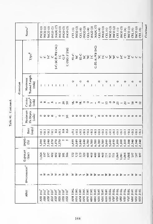
r~u rr» rr» fn to m w> rr»
O<z cj — u — cj — z u —; <j ~ «u — <j — u —! o
3 o o o o o o ou u u (j u u o
CO Z Z 2 Z Z z z
oz £
uz
-o CS Oi03
a.
Hu u V U 4-'
Uto
(?in
u
Si
u
J Z -> Z Z ~ -Z- U ZZ U « U - UUUto to ci
*h *-
Jto
u
J3
§ %3 U ^ ooo oo oooo
a 1 J -='Sup 1 1 1 1 1 1 i i 1 1 II 1 II 1 1 1
os s
ou
3
aj -a." c 'w
u S" £-o oo _, 00
100 O J O i—
1 O O _,i
O_mOOm„O_»C0NCOCO ' .-< N (S <H rH
U D 3
E .c
g &.oE u J5 o o O o o t- O oooooo
| oooooooooooo* Q E
1 u-> 1
ss"^
ai .E
00 ^o
o o o o o o o o oooooooooooooooooooV V V V V vvvvvvvvvvvvvvvvvvv
_c o o o o o o ui m oooooooooooooooooooa. p O rh Tj- t^ t^ t-N + + + *0003000000 + **0000+*'d-Q in N N tM <V1
\ONO^ONOt^t^r^t^r^ vO'O vOrAmmrorrirrirrtiftiftinift^^^\0^inininmiftifiviNNN
3 ^ + r^ t-^ (S ts CM 1H VO rftfr»rr»rfirrimrompo»—(t—l»—l^t*Tj*rJ-Tj*t^t^t^o & ^O Ov O o o o oo o c)CSCMr-l©00©Oln>r>u->*0^0'O vOO\0\0\
°_ rt '' -t -t -t- T—1 (VI rtrHrtrH^-^^-^^IVlSNqOq^qrtrtrHX ^ 1—1 fH t-H^ t-H t-T
w
„
cuEco CO ^ CO ^ «: 00 ^ £ ^^toco^^^toto^^to^^toco^^co
o
3
JJJJJJJJJJJJJJJJJJ.JvO MD \0 VO Xo o vO ^O sOOO^OsOnO^O^O'0\0\O^O vO s©vOO^OnO^O(*i m m rr, m m « rr> rr\ rri m pr> m pft ro (y^ m m ro co m m p^ rv* m cr* min i/i i/i X C/3 CO C/3 CO cococococococococococococotototocococo< < < < < < < < <<<<<<<<<<<<<<<<<<<
148

u
3O00
INCO
(3)
CEL
(4)
INCO
(3)
NADC
(7)
CEL
(4)
INCO
(3)
CEL
(4)
INCO
(3)
INCO
(3)
CEL
(4) OOOOOOOOOOOOOOuuououuuuuuuuu^ s
z1
<£ z
ao
u
uI-C NC I-C G;WB(S-L;T) C I-C
E;P(PR);T C I-C SL-E ZZ.i~ZZ~Z-Cii.iZ~ u uz z
Maximum
Tunnel
Length
(mils)
o o1 1 1
o oo1
*.1 1 1 1 1 1 1 1 1 1 1 1 1 1 1 1 1 1
Crevice
Depth*
7
(mils) _ O „ |m _, O m __ O
cm© © — __oo_©__,„ — o_ O O
Maximum
Pit
Depth
(mils)
O O O|o © m © O O
CMOOOOOOOOOOOOOO o o
(3 E ©'©'oldV V V V
o o o o oV V V V
OOOOOOOOOOOOOOvvvvvvvvvvvvvv o oV V
Q. "p
Q
o o o o o*t r-» r^ f- t-»rr, m m n-t m
O m in m m OOOOOOOOOOOOmm^+oooO"J-'*00'+Tt-t--r~-NO^Ot^r^vONOcnmrnrcimm
o o* <*
in in<S <N CM <N <M CM iniAvO^OinvjinirtNNNN
u
1 *O rt
a. -ax ^w
t^ N N N No © o © ort •+ rj- Tj- Tj-
CM i-H rH ^O 00O 00 00 VO ot^- i—< i-h m m
rrimrnm~~tj-'<3-r~t>.CMCM~\0cMCM©©min\0\00\0s©O00^O>-ii-iThTl-t~.t^OO'-i I-iTh^-i-Hrr>
CM CM
cuEco'>
cW
oo ^ ^ ^ co CO £ £ £ £ ^00^00^00^00^00^00^^ £ £
<
_j j j j jvO ^o *o *o *©
-J J J J Jr^r^r^t^r^t^r^c^t^t^t^c^r^r^
CM CMwi rfi ffi m m m m m m m mmrc^mmmmmmmmcrimfnCO CO CO CO CO
< < < < <CO CO CO 00 00
< < < < <oooooooocooooooooooooooooooo oo oo
< <:
149
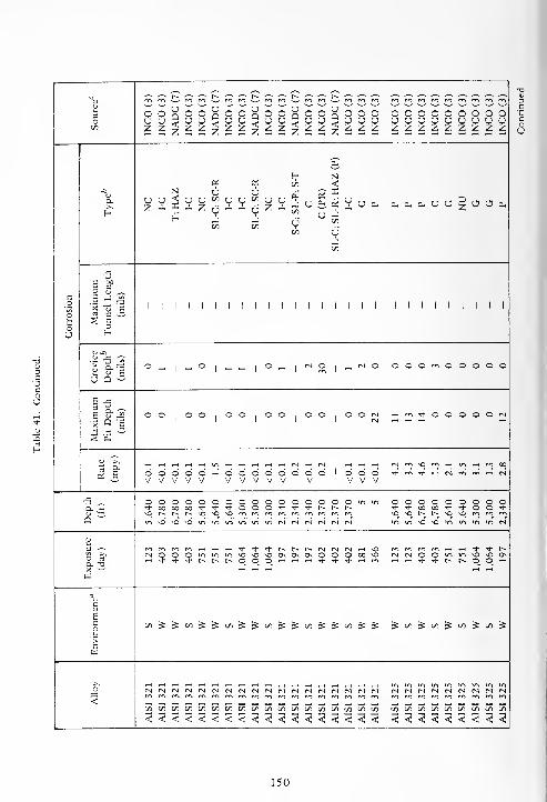
V rn£2
"' "' 1,1 '" 3C3C3C3^Ci^C!!i^o o n
Ua<O
z <O O U
<O O U
Q<O o o ooooooooo
o u u U u U u u I ) u u u sJUUsJUCJUsJUto z z z Z z z z ^ z z z zzzzzzzzz
cu
H No. c. </> <
a.>s
u uz -
N< u u
z
uto
v"
yu
y to oz y
cu
_Jtou y U Cu cucucuUO§sJOcu
J J O c/l
(/I COC/3
-Jto
JZ
g c2 K ~
a E JJ!'55 2 « G
1 1 1 ' 1 1 1 1 1 1 1 1 ' 111,11111j2 c o
oU
U -Ci
° J3 ^a fl
o _,1—
'
o1
_ —1
o rnI
ra o1
_, P-l o oooooooooO Q —
E .a
c P-^ o oI
° o o °1o o o o o O Psl Hm*OOOOON
a Q gp-1 rH rH rH rH
s a
^rH rH rH rH i-i in r-l rH -H rH rH psl rH p-l rH rH rH psimsor^rninrHmoO
(S £ o o o o o rH o o o o O O O o 1 O O O ^m^rHp-imrHrHPsIV V V V V V V V V V V V V V
JS o © o o o o o o o o 3 o s o o o in in OOOOOOOOO** 00 oo oo •+ + TT o o o -1- -1- "+ r-~ r- r» -ti-ooaj't'tOO*
l» ZZ- so r-~ r~ t-» o SO sO m m m m p~ m m m m sosot^.p^sOsommmQ in so so SO m m in in in m Psl Psl Psl Psl Psl Psl ininsosoininininpsl
3 t- * "* rr 1-- r^ rsi Psl Psl rH SO mmPTimrHrHT^rJ-r^O rt
Psl O o o in so so sn ON Os cjs O ra O 00 so pslPslOOmmsosoosrH + * <sf r» r~ !>. o o O 1-1 ^ 1-1 -t" -t •* rH m rHrH-^Tft^t^OOrH
X --'
w
a
c
Gao CO »S ^ C/3 £ 5= C/5 £ £ CO =5 £ CO £ £ C/5 SZ £ ^co^to^to^to^
cw
>sfN <N p-l p-l rsi rj r-j rsi r-l Cs| r-j rsi Psl Psl Psl N Psl NNNNNNNNN
<rn m m m m m rr> m m m rrt m m m m m m rn mmmrrsrrifnmmrPiCO CO to to to CO to to to -to to to to to to to to to cototototototototo< < < < < < < < < < < < < < < < < < <<<<<<<<<
150
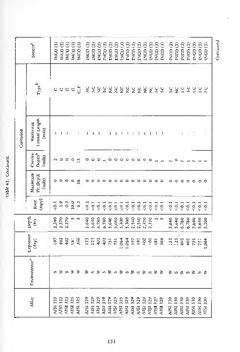
m CO Wi rv-i c/-) rv-i r« ^ ^r m rn mo o o o o o o o o o c o o o o o o o o o o o o c o ou u u u u u u u u u u u u <J u u u u u u u u u u t
;
uz z z z z z z z z ^ z z z z ^ z z z z z z z z z z z
u o u u UUUUUUOUUUUUUU UUUUUUUZZZ-1.ZZZZZZZZ-- iZA -i-H
E £>
E JJ5I I I I I I I I I I I I I I I
(vl ooo„oooooooo„_ _o„„„„_a
E J5
oooo^o oooooooooooooo ooooooo
oooooooooooooo ooooooovvvvvvvvvvvvvv vvvvvvvoooooooooooo o o o ~> o o o* ^t- oo on <* + o
VO md c« t^ ^o vo ro
t^ N N H \0 rnr^mrri^H^HTh-^-t^t^-^NlfvlT—IVO rrirrirri<3\ O © 00 MD (NtSOOuvu-ivo^OOCNOOOOvO r-1 C-l Oi-H * * rt en -H^HTj--^-tv.r~.00-H'-irt-'J-^-irr> ,_, ,-i t|- >* r- r-. o
C/i ^ C/3 ^ ^ ^W^C^^lZl^Cfl^CAl^CO^^ ^ CO ^ CO ^ CO ^
u-i uv uv uv uiN N N (S N OOOOOOOin l/l 1/1 !/) 7) COCOCOCOCOCOCOCOCOCOCOCOCOCO CO CO CO CO CO CO CO
151
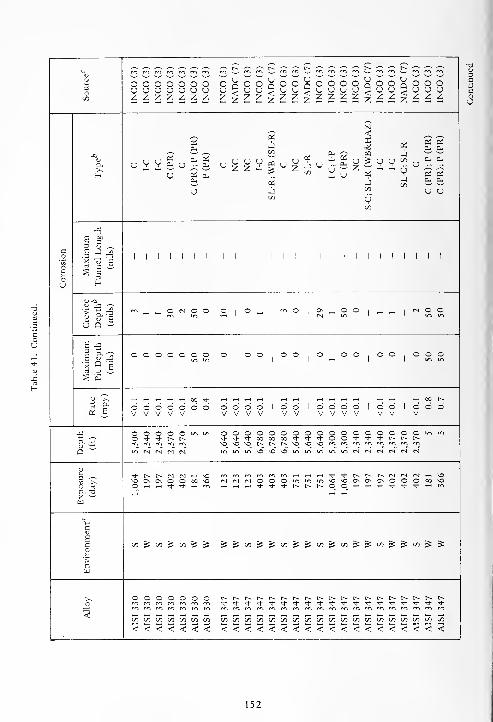
_, ^^ ^ _, ^\)
cr* m m c*-» rn «l co
a o o o o o o oINCO
NADCINCO
o uQ<oz
° O O O o UQ<o oH O o o
o5/3
u u o u u u u u u U O U u Uz < U u u
z z z z z z z z z z z z z z /. z z
N
2<
Pi Oh CU
U en
- uJ
a,>>H
c I-C I-C C(PR c(PR);P
P(PR
,, u uu z zu 03 u u
zOf
V u
CL, CU
u5/3
v"5/3
u u
J3
s g>3 t^
a E -J J2 . . . . . .
1 1
X U E
^ 5ou H
<u -a
1 f 1"> _ — © n o o O
|o —
1
m °1
0\ _ o5N in
©1
— -1
r-l © ©
U Q —
6 -S
I &5 © o o o o o o ©,© o © © . o o © © O
|© o o
a Qs
§ -a
^^a >> 00 t-»
© © o © o o © © o © © 1 © © 1 © © © © 1 o d 1 O © oV V V V V V V V V V V V V V V V V V
-C O © © © O m in o © © n O o © o © © o © o o o © © u-, in
Dh £ O -3- Tt- I> f» ++•* 0(3 on 00 <*• * <* © © -t -t- + r^ t^ t~m m m m m \o o md t^ r» i> \0 O \0 cv> m m m m m m f-l
Q *" i^ N N N N ^ •" "> ^O vo VO in m in in in <S (M r) N fS N
a x^" N t^ N N h ^C ^ ^ ^ m m « <-i tj- •*• r^ 1^ r~ fN (S fS rH v£3
M3 On 0\ O O 00 MD (M (N (N O ~ o in so ^O 0\ O. CN o o © 00 \oO rt O >-l »-i <d" •* iH m * <* •+ r-- r^ r~ o o 'd- <* -+ i—i ma. -o rH ,-H rt
w
„
c
Eco
5/3 ^ CO ^ 5/3 ^ ^ ^ £ C/3 £ £ 5/3 £ £ 5/3^5/3 £ £ C/3 £ £ 5/3 £ £
>c
© O © © © O O t-- t~- r-- f^. f» r^ t> t~- t^ r- t~- r~» r^ r-~ f~ t-- r^ r^ t~-
* + * * -t- -+ ** * * * * -i- -+ + Tf -d- * ^- ^<
m m m m m m m m rn m m m m m m m m m rr> m m m m m m m5/3 5/3 5/3 5/3 5/3 5/3 5/3 5/3 5/3 5/3 5/3 C/3 5/3 5/3 5/3 5/3 5/3 5/3 c/3 c^ C/3 5/3 C/3 5/3 5/3 5/3
<<<<<<< < < < < < < < < < < < < < < < < < < <
152

X U Jo<(uDii/)i/)inh^
C — r- rt
x "S x (J^ 2 | .H Sw I £ J §
C rt
c a 3 *>
II II II II
O fi "o<X _
153

Table 42. Stress Corrosion of 300 Series Stainless Steels
AlloyStress
(ksi)
Percent
Yield
Strength
Exposure
(day)
Depth
(ft)
Number of
Specimens
Exposed
Number
FailedSource"
A1SI 301 24 62 123 5,640 3 NADC (7)
AISI 301 32 82 123 5,640 3 NADC (7)
AISI 301 62 50 402 2,370 3 CEL (4)
AISI 301 94 75 402 2,370 3 CEL (4)
AISI 302 22 50 402 2,370 3 CEL (4)
AISI 302 33 75 402 2,370 3 CEL (4)
AISI 304 14 30 403 6,780 3 NADC (7)
AISI 304 35 75 403 6,780 3 NADC (7)
AISI 304, sensitized 14 30 403 6,780 3 NADC (7)
AISI 304, sensitized 35 75 403 6,780 3 NADC (7)
AISI 304 14 30 197 2,340 3 NADC (7)
AISI 304 35 75 197 2,340 3 NADC (7)
AISI 304, sensitized 35 75 197 2,340 3 NADC (7)
AISI 304 14 30 402 2,370 3 NADC (7)
AISI 304, sensitized 14 30 402 2,370 3 NADC (7)
AISI 304 16 50 402 2,370 3 CEL (4)
AISI 304 35 75 402 2,370 3 NADC (7)
AISI 304, sensitized 35 75 402 2,370 3 NADC (7)
AISI 304 25 75 402 2,370 3 CEL (4)
AISI 304L 14 35 123 5,640 3 CEL (4)
AISI 304L 20 50 123 5,640 3 CEL (4)
AISI 304L 30 75 123 5,640 3 CEL (4)
AISI 304L 13 30 403 6,780 3 NADC (7)
AISI 304L, sensitized 13 30 403 6,780 3 NADC (7)
AISI 304L 20 50 403 6,780 3 CEL (4)
AISI 304L 32 75 403 6,780 3 NADC (7)
AISI 304L, sensitized 32 75 403 6,780 3 NADC (7)
AISI 304L 30 75 403 6,780 3 CEL (4)
AISI 304L 14 35 751 5,640 3 CEL (4)
AISI 304L 20 50 751 5,640 3 CEL (4)
AISI 304L 30 75 751 5,640 3 CEL (4)
AISI 304L 13 30 197 2,340 3 NADC (7)
AISI 304L 20 50 197 2,340 3 CEL (4)
AISI 304L 32 75 197 2,340 3 NADC (7)
AISI 304L, sensitized 32 75 197 2,340 3 NADC (7)
AISI 304L 30 75 197 2,340 3 CEL (4)
AISI 304L 13 30 402 2,370 3 NADC (7)
AISI 304L 20 50 402 2,370 3 CEL (4)
AISI 304L 32 75 402 2,370 3 NADC (7)
AISI 304L, sensitized 32 75 402 2,370 3 NADC (7)
AISI 304L 30 75 402 2,370 3 CEL (4)
Continued
154
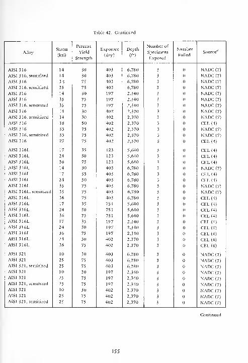
Table 42. Continued.
AlloyStress
(ksi)
Percent
Yield
Strength
Exposure
(day)
Depth
(ft)
Number of
Specimens
Exposed
Number
FailedSource"
A1SI 316 14 30 403 6,780 3 NADC (7)
AISI 316, sensitized 14 30 403 6,780 3 NADC (7)
AISI 316 35 75 403 6,780 3 NADC (7)
AISI 316, sensitized 35 75 403 6,780 3 NADC (7)
AISI 316 14 30 197 2,340 3 NADC (7)
AISI 316 35 75 197 2,340 3 NADC (7)
AISI 316, sensitized 35 75 197 2,340 3 NADC (7)
AISI 316 14 30 402 2,370 3 NADC (7)
AISI 316, sensitized 14 30 402 2,370 3 NADC (7)
AISI 316 18 50 402 2,370 3 CEL(4)AISI 316 35 75 402 2,370 3 NADC (7)
AISI 316, sensitized 35 75 402 2,370 3 NADC (7)
AISI 316 27 75 402 2,370 3 CEL (4)
AISI 316L 17 35 123 5,640 3 CEL(4)AISI 316L 24 50 123 5,640 3 CEL (4)
AISI 316L 36 75 123 5,640 3 CEL (4)
AISI 316L 14 30 403 6,780 3 NADC (7)
AISI 316L 17 35 403 6,780 3 CEL (4)
AISI 316L 24 50 403 6,780 3 CEL (4)
AISI 316L 35 75 403 6,780 3 NADC (7)
AISI 3 16L, sensitized 35 75 403 6,780 3 NADC (7)
AISI 316L 36 75 403 6,780 3 CEL (4)
AISI 316L 17 35 751 5,640 3 CEL (4)
AISI 316L 24 50 751 5,640 3 CEL (4)
AISI 316L 36 75 751 5,640 3 CEL (4)
AISI 316L 17 35 197 2,340 3 CEL (4)
AISI 316L 24 50 197 2,340 3 CEL (4)
AISI 316L 36 75 197 2,340 3 CEL (4)
AISI 316L 24 50 402 2,370 3 CEL (4)
AISI 316L 36 75 402 2,370 3 CEL (4)
AISI 321 10 30 403 6,780 3 NADC (7)
AISI 321 25 75 403 6,780 3 NADC (7)
AISI 321, sensitized 25 75 403 6,780 3 NADC (7)
AISI 321 10 30 197 2,340 3 NADC (7)
AISI 321 25 75 197 2,340 3 NADC (7)
AISI 321, sensitized 25 75 197 2,340 3 NADC (7)
AISI 321 10 30 402 2,370 3 NADC (7)
AISI 321 25 75 402 2,370 3 NADC (7)
AISI 321, sensitized 25 75 402 2,370 3 NADC (7)
Continued
155
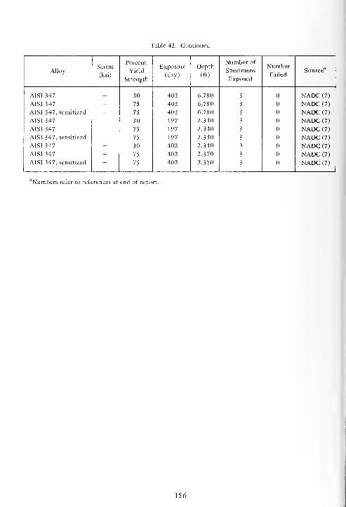
Table 42. Continued
AlloyStress
(ksi)
Percent
Yield
Strength
Exposure
(day)
Depth
(ft)
Number of
Specimens
Exposed
Number
FailedSource"
AISI 347
AISI 347
AISI 347, sensitized
AISI 347
AISI 347
AISI 347, sensitized
AISI 347
AISI 347
AISI 347, sensitized
-
30
75
75
30
75
75
30
75
75
403
403
403
197
197
197
402
402
402
6,780
6,780
6,780
2,340
2,340
2,340
2,340
2,370
2,370
3
3
3
3
3
3
3
3
3
NADC (7)
NADC (7)
NADC (7)
NADC (7)
NADC (7)
NADC (7)
NADC (7)
NADC (7)
NADC (7)
''Numbers refer to references at end of report.
156
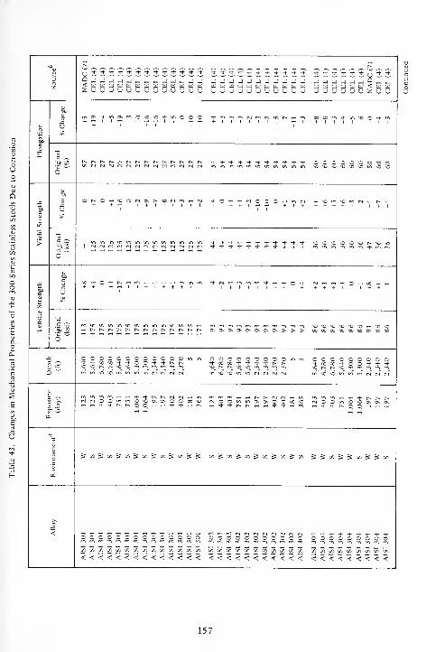
-o r~ t^
3Ox
u *'*'*--S-^-'J-^-*-^-n-Tt-^)-TJ- ^t-^t-^-'i-"*-*'*'^-'*^-'* 't*t.'t* u 't^
___________ W_JtdCLltLlW<WWuuuuuuzuu
o
c
boc
Girj0\-si-mc\m©*0*0'3-!^000
+ i i i i i +
Ttf-mmm<Nf*.r.mr~.-<ro+ 1 1 1 1 1 1 1 1 T—< +
OOXw^t-mvOO^-^
6
r^r^t^r^t^r^r~r-r^r--r^f~r^r^ ^-^-^Tj-Tj-^f^-^J-^l.^.,). ooooooooo
c
x
>
&oc
5Ot^O—'NOOr.CNt^OOC.r<.-,cN
1 + + 1 H H + | + + + + +.+ + + +
c o
oi B~™3™H™ *t'<J--^-Tt- ,i--<i-'3-'<J-'3-rt-^-
c
x
c
h
'O
+ + +—II + I+ + +II + + + + +1I++ + + + + I . I + + +
'5b !? ^-•r^c^t^r^t^t^r^r^r^r^t^r^t^ OsO\0\OsO\0\O^CvO\CvG\ GOOOOOOOOOCOOnOOCOO
OOOOOOOOOOOOmu. OOOOOOOOO". in ooooooooo^-ooxrt-oo**-*ini^vo^Oi^iminu-itMNtNM n.iOinmNNNN «i«<JmmiiNNN
a. td
<Nr.ootn»n*o*OO\CvOO00NO m n "i -'—' t^ r^ <N <N —. u.r.oOmmc\C\OO00*0 c.00m*0.3CvCNOT-t*^-t~0_0_BHrt— I
1
o
c
J»l5»lJlo5l«Jo)J»)JJ x^x^x^x^xjx &Sx&SxSSx
_o'
oooooooooooX X X X X X X X X X X
OOOOOOOOOxxxxxxxxx
OOOOOOOOOOOOOOX 7. X X X X X X X X X X X X<<<<<<<<<<<<<< <<<<<<<<<<< <<<<<<<<<
157

-Cs
3Ot/3
r^ r^ t^ r^ t^ l-»
9 j -j j< W U) wZ U <J u
U«WBBWW<aU<<W(JUCJUUUUZUUZZO-J -J J— - -u u u
ldUUUlUUU[ilU<lilU<lilUuuuuuuuuuZuuZuu
O
Co3
u777- C00vNHN7i*O\O'tM -3" NO t-^ [^ Omr^Tt-vOmmt^oo^-rvJONNONO
1 1 1 1 I 1 1 11 + 11
o
0000in ^0 O O
\ONONONONO*ONOinONO I 1 *0 NO -o NO mmininmincNinMNOininNOininminininmmininm-+mm^-inin
c
on
>
cmc vO IN N
1 + + +inNONO-tf-NOOXtNmON N ^+ + + + +"• + rt + 1 1 1 rt
00 w ri-
+ + +OOsOOMONONt^^Tl-fnONr^r^O
+ + + 1 + 1 +
O "t^ O O *0-+ m m m OOOOOOONOON 000* + * r^t^r~t^r~r^ooc^ooi>r^r^r^t-~^
60C
c
c m O w ^+ 1 1
ininr^rnTt-c-lrnmrHr-lOON"*+ 1 + + + <^» + + + 1 tH 1 +
N+ rt r-l
+ + 1
O-iw-HriiN^HnM^HO^^iNrj+ + + + + + + + + +-!* + +
""
1-1 NO O vo0\ 00 00 00 oooooocooooooor^ooool loo 00 CO CO cocooocooooocooooocooooooocooo
c
O O O mr^ t^ t-^
M N N
0000000000000+ C0l)S*i-OOi, 't'*NNS\Ot^r^*0*Ornmrnrnmmrom
O in m OOOOOOOOOOOOOOO'i-0000-+'l-OOOOT|-T)-^-C^t>t^
inNOxo>nininm<N<NN(SNrJ CM inNONOmminininmcN<NCslc^<N<N
1?Q_ -O
O O O 00St- •* * .H
<NOOinm^0O0\0N0\OOO O 00 NO* rH m
<NOOinm*o\o*0*O0\0\0\OOO,-.-+-*t-~t^O_0_0_0_^w.-<Tt-'+.*
c
1co">
cw
SJmS cn^cn^on^cn^^cn^^^ s & cn^oo^cn^&cntn^^on^^cn
>>_0
<
tj
1
0000
a
•a •§
T3 c
OOOOOOOOOOOOOJ J -J
000
TJ
C
nononOnOnononononono*OnOnOnonomrnmmrr.m^mrr.m^mmmm
« (/) w w ifiy5X[/)[/ii/5^^[/3«^y)« 1/1 « »1 cncnc/lcnt/:cnc/lcncric/Ncnc/NcncOcn
< < < < <<<<<<<<<<<<< < < < <<<<<<<<<<<<<<<
158

c^ t^ c^ r>~ t> c^ t> I>
\r.
-J -I
u u
JJJJJJJuuJJJSaMticqati;a<<fc;wfcittiUnJnJUnJnJnJZZnJUnJnJ
u u uC Q Q< < <Z Z Z
ua<z
Q Q< <z z
co
boc
X .-<
+ 77'+° + +i
° t t " +O X -nO On On O
+
c ^
6ss X X X X X X X , CO a 03 M
"* if •* -J- * Tt" * ' * + * rhO O m R NO NO
So
>
M^ CN NOmHOmMOvOnNNm
1 + + III 1 + 1 +O in m
NO ++
°1
r» c^ x x x x x x oo x x x x1 1
£ R1 1
t/3
c27 _H„„„ „ rt0,00—i O CM
1 + + + + + 1 + + 7 £~ X+
C cn+
O~ 00 CO
o ^o ^o *o 'O ^ 'C *o no no noX X X X X X X 1 IXXXX m m oXXX oX
N+ -*On On
Q~OCOOOOCOOOOm^-l-xx^-^J-^i-^-r^r^t^r*
o o o-t c o
o c oNO NO
in>O^Cmir>MiNtNM(sr-)
1 >.O aa. -oX —
X "Ommrri^^<t^c^<Nfv|MCvl»^u^<NCO«nmooOOOOXO-« if- -+ r- r^ — — -* -t -J- + ^ m
"> * tt!N NO NOh CO 0_
Osi-H t~*
c
c
5 £ cn&c/55x5xSSSx55 s s s * 3: S
1 -0 o
-a -J
OnOnOnOnOnOnOnOnOnOnonOnommmmmrowmmmrornm
V, X x c/3 x IT. x x x x x x x x x X X X c/i J~j t/3
< < <<<<<<<<<<<<< < < < <c < <
•o c
o -a
S E
s 2Z S
159
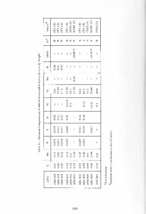
a ^ t--"~*
t-.(V^
TT -t- * "* —
'
u -t- Tt-—
U-
—
c O O3OC/3
J J J J Q ,-J J a<w w to to Z to to Z zu u u u z u u z
"vto
to to OS to a:« « Di a! to to
> >u Os o
1 1 1 1 1o
1 1 1IS
I
O oV
oV
so r^
< d d d1 1 1 1 1 1 1 1
o III 11°. 1 1 1 1 1
o
vr> o o o}H so * m m 1—
I
T—
1
Tt- in r~ © oo (N rJ * fs) ts *N SO SO r^ o
Or\i
z ! I I
o ts| 1
tH1
tM fN
o o O o OV
SO I-~ r~- SO SO
0Din m c-i *
1 1
"? "J 1 1 1
O © O o o o
OS in o m©
OD o o o o 1 1 o o 1 O 1
o o o o o o O
I-~ * Os Os »NM N
a. o o o O 1 1 o o1
1 1
o o o o o o
c in IN m o t^ sn o-+ oo so ^t- ^ * -t- * ^t- 00
o o o o o o O o o o o
SO in m rrt t> in so so in
u o c © *—
<
^H ^H o O O O i-H
o o o o o o o o o o o
o o o o o o o SO© © ~ *-d-
-!- -1- •* ^- <+ * st- * ^h *
< J-. s. V / r on
< < < < <; < < < < < <
160

"* •*• * * <*- * * + * + * *
CEL
(4
INCO
(NADC
CEL
(4
lNCO(
+ --' u T(- * U * —
'
INCO
(
CEL
(4
INCO
(NADC
CEL
(4 — *^8W n>
Cuz
Ouz
_i8J zU 38^7 a- u
_o -j -J J J -J -J J J J J J J u J -J u
_ - _ - _ a ______ < u HI
_ u u u u u u u u _• u u z u u z
F- E- E- H H E-
t-^ ,_: ~ (_ (_ ^ ci «oi 05 a. !_ ~ (_ ~ ci a. _ _ H OS a. a. ci-
a, (_ £ H H.E- E- E- E- * -'
E- H a. c ~ a. dS u a. (_ w a. — a.
a a a a ^a.
a"
a.
5
u
a. V. V. •- - c_- a a _ U a.
I "u
" a. \ ~ a.
- Oi - uV VJ Jon on
c_ a.
a,^
w uu
a.
5a.
U
u
2a.
u
2a.
UV
_, ^jA" _;oi a.
— Uu
C
(PR);
C; C(P
S-C
C;
E sj a-
£a.
_
1 t coo - O in O O O O o o o o - o o o o Oin CM 00 in o o X X o o o o
_ =*1 * 1
<->1
X o °1 1
°1 "1 o
_ _ vO
5^ p
o
o"-> u-a
(M O O m — O J o _1 J o o o o sf) o o o COO m M OI S- ^ _ O —< .H m * m _ -f -i- in 7J * in in rt on —i -i *U Q
c _
IS-o, O O O O !N fN <n o o o rg * o o o o o o o o o r> o o
_ sn _ -3- <n ts + n1 t n
1
•* * 1* m
^ •-' —
'
<u ">. t O ^ i- 0D in —• -* -t oo O in (N rH ^h ro rn CN Ov o ^ * * t». » m m <n !N m
« o- O rn o O IN o -1
- o * 1 O r-. O O r-l| o O O
~ CV V
O O O O O m o o o o o o o - n o o r> o o O O O O OX 00 00 a: M -+ -1-
Q'~ _ _ r^ r^ o _ _ so so _
_ vO _
_ _ _ _ min (N fS (N (N^ "-> o o "~> m m N in o N
B-J- r^ r^ eg cs oo
.- _ o O* O O X tN IN IN IN (N o o ". - in OO H « t + ^1 * * * + -t r^.
w
c
c J Si J M S 5: in J « 5 oi S 5 Ji«» s * 5= tn C/3 S S & «> 5 »5 5 J M on ^
c
o o o o o o o r> D o - O O O O OO O O O O O
° -t -t- -t -1- -t- + -1- 1- -t -t -1- -t •4- -t * -t -t <* * >t •* -t * + -t •* •* -!•+•**+ * •*
< < < < < < <<<<<< < < < < < < < < < < < < < < < < < < < < < <
161
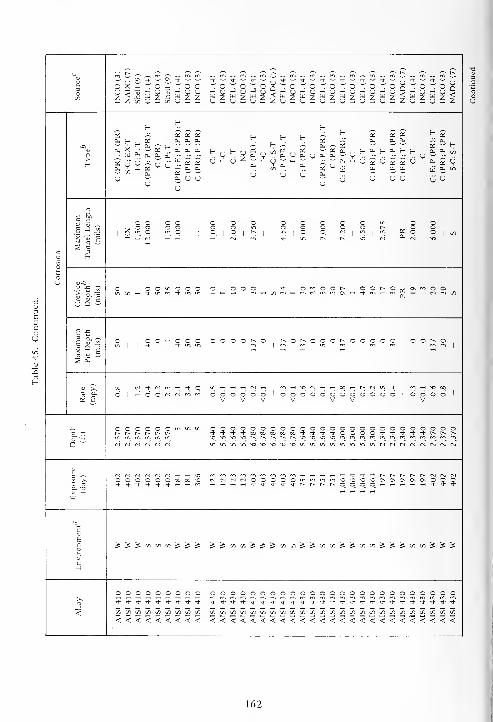
Os £ * — u S< wZ U U-ZU3CJ3Z
3O
OCJZ
Q<Z l CJ
OCJzi^3£ W 7x CJ -
Ouz
J ° J ° J °—
J U J U J uU 7 PJ 7 w ^U 3 u S u £
8^3 CJ
3^7 us3 CJ
CJZ^8U 3
^8
E-E-
E-H £ £ *- £02 oi oi a! H H f-
02
cu DS Oh CU cu OS x 0-0. „ cu ,H JC a. OS — r a;w tr
a.a,
s
a.
CJ
,. fcl cu
u ~ u ^ ~en a
ena.
(J Cu 0,
u
£_ CU t- cu H (-. a. cu en
u £ £ u«h £ V
Cu 0- 2- fH £
v" v"=h w pu c
*cu
OS ^ u CJ CJU(J
5j u CJsj
u sj CJ vj JUu
E &3 S o o o o o m O OS -J X O O in o o o o o ^ ^ O O
F1
q.1
">. °.1 1
°.1 °- 1
*--1 q 1
°.1
so
m„ 1
* °. 1°
1en
rs\ 0- M so
o H
p
ou aj-a
in o o o o o o o Ti- o r~ o o r^ O q£ Os i^i o O" m
O.rt rsl m x> a.
Fm 1/5 "" •* in m * in m ~* ~ ~* ro « en ro — rr, <N in m OS — -+ rn
CJ Q
E "S3 Q. n n -i o o O O O O O t-» o r^ o t-~ o o o I-- o O O o o o o c^ o'S
° 1 1* -r in
F rt rf rt w rt
S a.
~=0 M * in ,-h -t O „, N .
rt rH SO rf rt X tH t-^ n in tI- m u « Mrt a- o 1
o o o o o o o o 1 o O O o o o o o o o do I dodo I
a: _6 V V V V V V V
O in in o o o o o o o o o o o o o o o o o oooooooor^ * -1- -T o o T|-ThTj-T|-T|-t^I^t^
Q " N « - « M Nso so SO so l^ f* r^ ^ I"*- sO sO so SO
in in in in so so SO so so in m in m in in in in rsicsirjrsirsirslrsirsi
Ijso * t1- -1- TT l^r--t^c^c^rsirsitN
& Tfo-t-
o C C X X SO rs! (N CM (N o O o o•+ -I-
O m-+ r- 1^ t^ R
sO so
q qsO so
q o_OsONOsOsOsOOO
a. -a
W
c
Ecp
s S £ X X «S5 5= 5 =s x x S S ^ en en ^ ^ en en S 5 en en SSSmwSSS
UJ
o o o o O o o o o o o o o o o O O o O o o o o o o OOOOOOOOTl- * Tt- * Th TT Tl- •* + * * Tt- -J- -1- Tf- 4- * t|- Ti- -+ •+ •* Tt- * -t Ti- n-^-TTTTTi-Tl-Tl-Th
< C/il T. s. X, x m ») in J-. X X x x X X en en en en vi en -T, en en en en xxxxenxxx< < < < < < < < < <<<<<< < < < < < < < < < < < <<<<<<<<
162
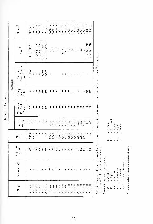
^v * w w -' * 5-mmrommm.mmrnrnrommm
3~ O O O ~ ~ ooooooooooooooH u u u H H uuuuuuuuuuuyuu
75 — Z Z Z — ^u - - - u u zzzzzzzzzzzzzz
t. OS OS ~ ~ OS OS
V. a. a es as 3. e.
-a ^ w wo. a.
zz z^zz V VuVu**a.OS b. a- —
•—
o- U ^c ^; eu cu
£ £ — —7. o- a-, OS OS
w u u ~ 5; u uCJ U
JZ
If c o oEJ« O m O
1 1 1 1 1 1 1 1 1 1 1 1 1 1in _ -fr m£ c
c 3o E-
o
oV
o oc o o o o OOO OOO N <N O Cis-!
in m in in — — — in in
u a •-
B -5
I 8-3 t^ o o o o o OOOOOOOOOOOOOO'i
° e wIs"
jj'>-
c _< h o o oooooooooooooo^ S vvvvvvvvvvvv
JZ O O in in in in OOOOOOOOOOOOmint~* t^ **o» + *oo* + ^>
a w 32sOOr^r^vO^O^n^n'nrr.mrnmmNO<3minininrj(N(N(N
a(N (N --< O O 00
« ~>, o c x >o <3* 00 <NrvJOOmmO*00\0\OO00OO a 4 t h rr, n n r-c«-J-*r~I^O_0_'--H**'-''»>a. tjx ^w
c
x x 5 5 5 5 St/55^S^5x&I/5SxiSS=fc[d
o o o o o o OvOnO^O*0*O vO*0*0*0*O vO*0'0
1
t -t i- * * t *i)-*'*'+-t'*if^-***rJ-Tf
<<<<<< <<<<<<<<<<<<<<
a •£
I .5
.3 " £ -C U
ij j- > .SP SS c t: t5 h
cl a. w (/) h
U u UJ bJ
a. >
<J W W W _ Z
163
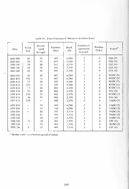
Table 46. Stress Corrosion of 400 Series Stainless Steels
AlloyStress
(ksi)
Percent
Yield
Strength
Exposure
(day)
Depth
(ft)
Number of
Specimens
Exposed
Number
FailedSource"
AISI 405 43 75 403 6,780 3 CEL (4)
AIS1 405 20 35 197 2,340 3 CEL (4)
AISI 405 29 50 197 2,340 3 CEL (4)
AISI 405 43 75 197 2,340 3 CEL (4)
AISI 405 43 75 402 2,340 3 CEL (4)
AISI 410 47 30 403 6,780 3 NADC (7)
AISI 410 116 75 403 6,780 3 NADC (7)
AISI 410 47 30 197 2,340 3 NADC (7)
AISI 410 116 75 197 2,340 3 NADC (7)
AISI 410 47 30 402 2,370 3 NADC (7)
AISI 410 24 50 402 2,370 3 CEL (4)
AISI 410 116 75 402 2,370 3 NADC (7)
AISI 410 36 75 402 2,370 3 CEL (4)
AISI 410 120 - 402 2,370 3 NADC (7)
AISI 430 - 30 403 6,780 3 NADC (7)
AISI 430 - 75 403 6,780 3 NADC (7)
AISI 430 - 30 197 2,340 3 NADC (7)
AISI 430 - 75 197 2,340 3 NADC (7)
AISI 430 - 30 402 2,370 3 NADC (7)
AISI 430 27 50 402 2,370 3 CEL (4)
AISI 430 - 75 402 2,370 3 NADC (7)
AISI 430 41 75 402 2,370 3 CEL (4)
'Numbers refer to references at end of report.
164

Table 47. Changes in Mechanical Properties of 400 Series Stainless Steels Due to Corrosion
Tensile Strength Yield Strength Elongation
Alloy EnvironmentExposure Depth c b
Source(day) (ft) Original
(ksi)% Change
Original
(ksi)% Change
Original
(%)% Change
AISI 405 S 123 5,640 77 + 1 59 _2 25 + 3 CEL (4)
A1SI 405 W 403 6,780 77 -33 59 -25 25 -61 CEL (4)
AISI 405 S 403 6,780 77 +2 59 -2 25 -7 CEL (4)
AISI 405 W 751 5,640 77 59 -3 25 -13 CEL (4)
AISI 405 w 197 2,340 77 + 2 59 -1 25 -1 CEL (4)
AISI 405 s 197 2,340 77 + 2 59 -2 25 -2 CEL (4)
AISI 405 w 402 2,370 77 -21 59 -9 25 -39 CEL (4)
AISI 405 s 402 2,370 77 + 3 59 -1 25 -3 CEL (4)
AISI 410 w 123 5,640 183 -52 155 15 NADC (7)
AISI 410 s 123 5,640 80 49 -3 31 +8 CEL (4)
AISI 410 w 403 6,780 80 + 2 49 + 2 31 -8 CEL (4)
AISI 410 s 403 6,780 80 + 2 49 -2 31 -4 CEL (4)
AISI 410 w 751 5,640 80 +4 49 -4 31 -8 CEL (4)
AISI 410 s 751 5,640 80 + 2 49 -5 31 -3 CEL (4)
AISI 410 w 197 2,340 201 -26 155 +8 9 -11 NADC (7)
AISI 410 w 197 2,340 80 + 1 49 -4 31 -3 CEL (4)
AISI 410 s 197 2,340 80 + 1 49 -3 31 -3 CEL (4)
AISI 410 w 402 2,370 201 155 - 9 + 3 NADC (7)
AISI 410 w 402 2,370 80 + 1 49 -2 31 -9 CEL (4)
AISI 410 s 402 2,370 80 + 1 49 -2 31 -7 CEL (4)
AISI 410 w 181 5 80 + 2 49 -9 31 -13 CEL (4)
AISI 430 w 123 5,640 72 + 5 54 -4 29 -6 CEL (4)
AISI 430 w 123 5,640 73 -1 55 -2 28 -1 CEL (4)AISI 430 w 403 6,780 72 + 12 54 +6 29 -22 CEL (4)
AISI 430 s 403 6,780 72 +9 54 29 -6 CEL (4)
AISI 430 w 751 5,640 72 -75 54 -100 29 -100 CEL (4)AISI 430 w 1,064 5,300 72 + 10 54 +4 29 -16 CEL (4)AISI 430 s 1,064 5,300 72 -4 54 29 -42 CEL (4)AISI 430 w 197 2,340 72 +4 54 + 1 29 -8 CEL (4)AISI 430 s 197 2,340 72 +6 54 + 3 29 -15 CEL (4)AISI 430 w 197 2,340 73 + 3 55 + 3 28 -10 CEL (4)AISI 430 s 197 2,340 73 + 3 55 28 -9 CEL (4)AISI 430 w 402 2,370 72 + 5 54 + 5 29 -18 CEL (4)AISI 430 w 402 2,370 73 + 3 55 +2 28 -20 CEL (4)AISI 430 s 402 2,370 73 + 3 55 + 1 28 -18 CEL (4)
W - Totally exposed in seawater on sides of structure; S = Exposed in base of structure so that the lower portionsof the specimen were embedded in the bottom sediment.
Numbers refer to references at end of report.
165

^ ^-a
u u Su n^. U-l + 4- -t rt + <* * —
'
* ^
5 1
O :r3 J a J u -j 9 J J J J J J JtO u < W <; w < w w u w w w w z W 7
u «u Z U z u z u u u u u u u
OS oS a; OS OS os a; OS OS OS OS OS OS OS OS OS OS
HK +
J3 u>
1 1 1 1 1
zH p
.- XIH sJ
1 > H 1 Z ZooO o Os d- OS in o SO o<N o o SO r^ ^h in l—
1
00 rh mo V o o o rH O o o o o
o o1
1U -1
m
. * Os ,_, in
< 1 1 1
i-H1 1
1
»"H o1
rs in1 1 1 1
-1 l-1 o o 1-1 rt
- os m in (N
% 1 1 1
t-H o o t~~1 1 1
(N Tt"1
O1 1
o (N m m <N (N rj N
rvl o in in o ,_, o^ os t—
1
-t- o o o m 00 oo o t^ o in o <* ou t^ t^ l> r- <* so SO Th -d- sO oo oo
o <s o o\ rsl Os o o rsl O r^.-H o d- t-~ ^H o o * oo 00 in i—
i
'd- in
z * * r^ t-~ t^ •* + SO SO so oo oo t^ so t)- o o
<s 00 ^* r~ ^f o Ti- * O r--
C/l 1
+1
CM1 1
m in t^ in en 00 (N1
^ 1
o o o O o © o O O O O
so Os so Os OJ N mo o a o
OO o 1 c 1 o 1 1 o o o 1 o o O 1 o 1
o o o o o o o o o o
r^ SO ,_, ,_, so 'fr o in ^PJ o rsi ™
1
Pli o 1 o 1 o 1 1 o o o 1 o o O 1 o 1
o o o o o o o o o o
C•* o on 0\ o t^ st SO o SO r- o rn o<N o * SO in
11
t-^ ITS in in ro pri1 Th in
o "H o o o o o o O o o O
c^ (N in m m * r^ m 1^
U o1
o1
o1 1
T-l o o O o (N O1
9 1
o o o o o o o o o O o
s Z Zin in
3 O ©
<so
oso so so so so \o so SO
ITS
SO SOsX op
4
>
SO
Z
to r. C/l C/l to 00 C/l 00 C/l to C/l C/l T J u u o< < < < < < < < < < < < eu rt <
166
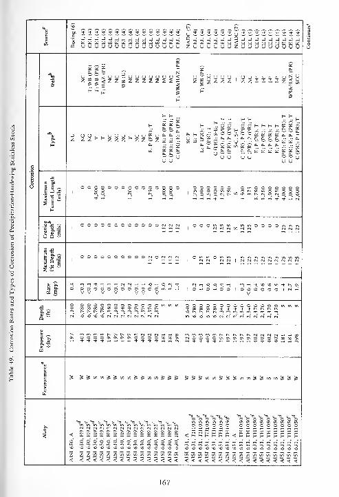
_ I
utu
t^ t^
"***^-'J-*T)-^t-^-Tl-T)-Tf^- * *(
j'*Tt-t'>l-^l-'>J-f,^-'^-'+r)-T)-T|-'*T)-^-3O
5 JJJJJJJJJJJJJ J J 9-j-jjj-ij9-| -| -l -l -i-J-i-:i-iBlUUUUblUIilIillilUUId w a <UWWWWCiI<UtilMUJIiiaWlilWUUUUUUCJUUUUUU u u ZuuuuuuZuuuuuuuuu
£££ §
a. ~ BJ
OS 0.
zgg<zzcazzzzzzT. T. x 5
N 0. ""'
C) <1 Z»i^ZZZ ' ZZ-~-i-iZ<&
o3£
Z X•a
H H 5_"
t-'
H oa
E-S- H H H - - f-
H. h u £ S , 2 £ h
.h
. t h. £ £ 2T. t
OS a.a.
'-'
w 0.
o.3Z ^^^^^^- O,f_0S'yl/l~'^'c/>-- — OS OS OS OS a. o. "^
rj -- a* OS •- a. a- - c- 0h 0* — 0- 0- - .- cut/i til
w a- P - •- U - - — *- ~ ~ til w -
°i a, £ os os « os os * "h °: <h ~ a- £f- a. ~ as
a as a: a. OJ 'O.O- OnCUtlJtlJl^tijOSOSO-2. a.
ww U U U U U ~ w uu u u uo
o J_
o1 1 ooooooooooocoS 2 2
1 r^omoiNt^c/^mrnr^fvjmtNOONO* — 1 rt rH rt •H «-- + - -h n mm* * rt N
s1H
U-fi OOOOOOOOOOOON O O O m in in ininoOOOminin£ s-1 -U D -
E -53 a. -*
1*1OOOOOOOOOONON
s s
* rtrtTf--Hrt-H<N(S^Hrt\0-HO (N ^f- (Ni-iNOO^t-i-H rn^^t-SO^OiriTi*t^O\OOOOOOOOOOOOmV V V V V V V V
x 000000000000^ in in OOOOOOOOOOOOOOminmQ w
*Or^r^t^r*mmmmmmmmr^N 10'O^NNMMN!N(NN in\Ooo^OMf^rsr^rjr^r^(Nfs
s t^ mmMm t.«.^^ NNN „- ^h 00OOOOONONONONOOOOOO 00 o\
a. ti,H —
'"^
w
Eco
S SJaioiJS»i»iJJ»i»iJ s 5 SSJ«imJSS»»iJJ»i«JJJ>cw
000000 OOOOOOOOOo
OOOOOO OOOOOOOOO&^ftCiftO^Oi^Oi^OiO>0\ 0\ ON xxxxxx xxxxxxxxx
5 < XXXXXXXXXIXXX X X <S-S-t-S-S-H<£-f-HHS-Hl-f-(-OOOOOOOOOOOOO7.
<
sOO'O'O^O^O^O^O^OnOOO^O \£> *o nO^O^O^O^O^OO^OOOOO^O^O^O^O^OC/3 lfltf)V)(0(fltf](flVlV](0(Am c/: on [fi(/)^^7iww(/i[/i(/i(/iuiwy)ui[/it/i<<<<<<<<<<<<< < < <<<<<<<<<<<<<<<<<
167
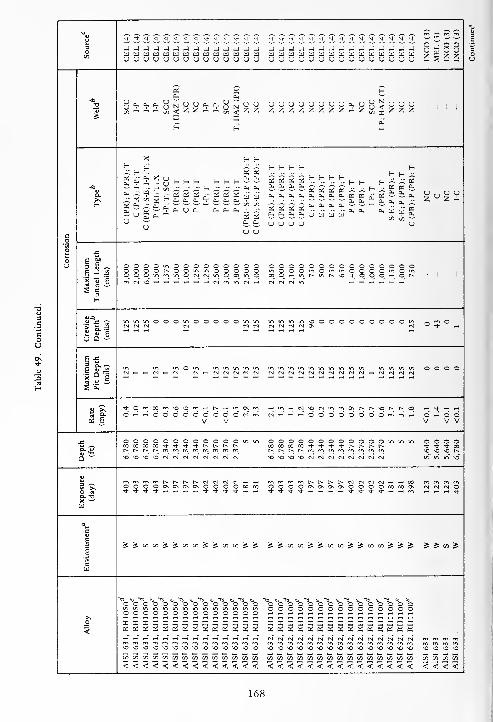
3oCO
O j O O-+ •t * * if *+*<)+ -+ -t -1- -+ *^-'i--3--3-^t--*-J-"4-Tf-n--*Tt- * +j rJ J J J J J J J J J -J J -J JJJ_1hJ_1J_1hJhJ_1_JhJ -J _)w HI ttf hi HI UJ HI HI W Id u hi HI W UUUUIillilUUMUIiJUU W HI
2 sSSu U U (J u u u u u u u u U u uuuuuuuuuouuu (J (J
OS as Ha. 0h
•a uuCO
.?.., a. cu
on < ^ ^ ~ — to
U (3 UUUUUUUOOhUHSuZZZZZZZZ--.Z^£Z u u~v >i -1. NM Z H z zS X
HX
Oh"
X H (-
H H-V y^s' H H H H HH as a:
A" OSOSflu <V X y H (- H H H
co ^; ^: x s- -^ a•- os os os j- os asr" a- D« CL i CL. Oh
H0- Oh £ £ £ £ H
.H
.H
.H. H H H 5
a.>S
a.
5 x 2£0h
0, Oh
Was Si?i Oh
0- A- as
z "gSH OS
a.
Oh
u^; a.
cu a-
°£ 0. U ft. Oh Oh Oh
s s£ £ £ £ <h * "h * ^ -T
~ £ £HHQjH-H-y^UIl]
u^L Oh u u u u u
c u uo
o JO
o1 S -u o o o o in O O O O O O n 3 o ooooooooooooo o oE J -2 n '> o o c^ O O m in o O o I
- ' o mOOOmOmm O O O O mo o O in m in O (N <S in O 00 o ooO^Hinr>-inrH,so-Hr OOO^H o t-.
x X E
S1S-
<U-C> « n in O O O in o O O O o mmmmsooooOOOOO O m o m O•* —
"if EU Q —
i-S1 8-3 in in mom mm in m m mmmmmmmmmm mm m m o o o o
""
s a
M O.
if
OO m CO m so so rn rH r^ rn m ON m rHm--irslsofs)inmONt^t^sor^ t^ CO ,_, •+ Tl rt
rH O o o o o o o o O ,M rt „ rt OOOOOOOOm o rH O O* jl.
V V V V V
O a O O o o o o o o o o in m OOOOOOOOOOOOm m m o O O o00 X CO 00 * it ^ if I-* r^ r-> oocooooo-tf-^t-^t--Hu c*-rHr^rH.
Q w1-h.
*o SO so IN Csl IN N rs] (Nl Csl -t^t^r^t^mmmrommrftm sO_ so so C^
in in so"sosOsosOfs)rsl(Ni(Srs)fNifNlfS
1?t^ r-H t^ t^ <N (N <N mmmmt^t^t^t^fN)rsl<NfST-i »H 00
r> -i o o ON ON ON ON O O O o 00 OOOOOsONONONOOOOOO CO ON* + ** -ij- rH rH -H rH Tl- ^- -4- * ^l-'t-S-'t-l'-'-lvHll-^-rt-^rH rH rt <$
a. t?x ^us
c
EBO
S S cn CO i$ j£ x x •£ c£ x CO & 5E jS-5oncoj5Scoonj5j5oncoi5&s2 & 5 on 5
>cm
ti »U <u "CS Cs, 13 tu"Q H> "53 » 13! 1 o o o o o o o o o O -- n oooooooooooooo s o o o o o o o o o o 3 o
ooooooooooooo o o
O I X X X X X X X X X X I ~ - 22^^^J222^2^2 I X3 OS OS x os X as os oS as as os OS as as ososqsosososososososqsbSos os as
m m m mNMtNNNNMNtNNMCslrsl (N) (N)
VO so so so so so so so so so so SO SO SO sosOsosososososososososOsO so so SO so so so
X X x x on on co on co co on X CO CO oncooncocococoononcoononon on on CO on co on
< < < < <<<<<<< < < < <<<<<<<<<<<<< < < < < < <

U^,^^-^^-^-^-^- •*•?•* •*OOiOOjOOOOOOOZ 2 Z Z Z Z
•+ * * <*••*** "* •**<!** *
s § 5 s
I I I I I I I I I I I I
JJJJJJJJ
I I I I I I I I I I I I I I I
3 U ~
is-5
(2 E
oooooooo ooooooooooooI I I I I I I I
o o o o
ooooooooooooo oooo
»-H^Hf^-H-HOO^^TH»HW^HW ^H <N ~H O
oooooooo
oooooooooooo
o o >o o o ooooooo oooooooo ooooVVVVVVVV V V vvoddddciddV V V V V V
D. £ooooooooooooo-*^-*ooo*^-t^t^
_-^_-t-t-J-|^!^r|
oooooooo ooooooooooo
\o^bvoo\o\oooo\o
\Q N ts *0
<NOO«->0\0\OO
no no t^ r^ no
»iJJioJii«S«iSoiSS SS</>SS<*>S(/3 S</)^t/5^g:c/5S(/jStf>S
uuuuuuuu+ jf * •*"
rf-"•+" •& *
no -o o -o NO o no -o -a nO no nO o -o o no o \0 no NO NO NO NO NO NO NO NO NO NO NO NO NO NO
f. r. X /. f, f. s, /. r. s. J) s. r. s. f. s, y, c/i en ITi (SI C/5 J: 1/3 C/3 w -r; J. w J-, C/3 C/3 I/]
< < < < < < < < < < < < < < < < < < < < < < < < < < < < < < < < <
169
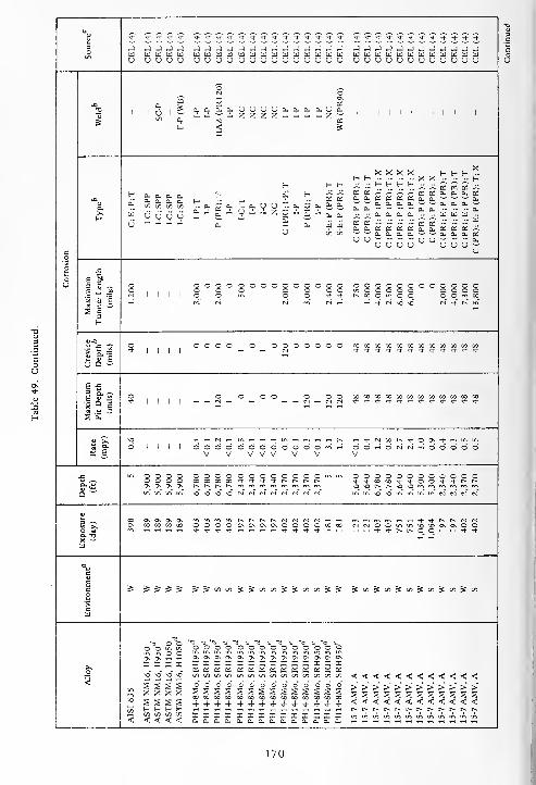
n?
3
* + * * •+ * •* •* * * -t * * •t * * *)- t !l-^-*-+*s*-Tt-^-^-^-^-Tl-
j j j j -J J -I J - J - -J J -) J J J J J_)JJJJJJ_)_)JJ00 w u u u u w U Id U UUld W U3 tU td W B) ai IdUlUlUUUUUUUUUI
o u u u u u u u u u u u <J u U U u u u UUUOCJUUUUUUU
©IS o
Os
c 03aS asa PL. u u u U Cu Cu CU Cu (J Cu
1 1 1 1 1 1 1 1 1 1 1 1
1 (j 1 w z z z Z - - z 1 1 1 1 1 1 1 1 ] 1 1 1
S N COCu < s
I
XXXX i- i~ f-'^.f- H --.-- X X •- - - H
H H E- p p fr. fr. 1 1 $ 5 as £ s «-o
t- — — — -.CU 0- Cu Cuoo oo oo oo
Cu
HH- cu U9^1
4" Has as
asas~ — ~ aSaSa.acuaScuo-aSasasaScucu — ~~eu
a.cu a- x °?
z £0.
u
'V asa. 5s Cu '"'^'CuCuCuCU'—'^^CuCuCu^^HHs/^^W^n g^
6"V V V V
— a,—
cu
— aCu
—Cu Cu - - cu cu a. Cu - - w a) u) -
asas---: — asas— ^" WcucuaSaSaSaSacuaSaSaS^;
00 00 ^'
'— CUCUCuCu^^^^CUCuCuaSUU^^^ — (ju-'^^cuoouu uuu^c u
o .G
o e |s S3 -^ O O o o o o o o © o o o o o o ooooooooooooE J J2 o O o o o o o o inOOOOO OOOO
I 1 ! 1 D o o_ o_ Tf_ •t t^ M_ 0_ in o 0_ O^ 0_ m 00_5»E h -t n o so cnT 4 r-~ f^iir ^
H
o O o o o o o o o o o o o coooxcoxxcocococococo
Ifi*
1 1 1 1
— _,rt
+**^-^-Tj-^l-Tj-Tj-Tj-Tt-Tj-
U Q -'
6 •£3 a. ^E g-J2
'1° 6
o o o o o o o o xxxxxxxxxxxx*1 1 1 1 N T|-T|-Tt-Ti-Tt--J-Tt-'*T|-^t-^t--*
s aw
SiSO
6 1 1 1 1 O-n-!l-<Nxr^-+OON*fnin>n
o o o © o o o o o o O m 00»HO(MfSrnOOOOO* S V V V V V V V V
j= m o o o o o o o o o o o o o o o O m m ooooooooooooo o o o 00 00 X 00 •* * * * t^ r^ r^ r^ ^^-xxTt-^t-oo-^-^-i^r^
Q "'C\ ON ON ON
so
c-* r-^ r-.
sO so so --- (M C*l cc ts
vosor^t^sosommmmfrjminin\ovoinmmints<NiiN<N
1 "£00 ON On On On r^ r*- r-^ t^ <N1 mrr) mrrjw^HTt--^-t^r^nMON X X 00 00 o o o o ON o o o O 00 rSTNOOminsosOONCNOO
o « * * * •* rt s* t ^~ 3- rt -H^ri-^-I^t^OO^'H^-'*Q. T?X — 4" rt
W
ac
eco
& JS5J •5 5 O0 00 s s 00 00 ^ S oo 00 5 S 5»S»)Si«SmJ»iJ»i
c01
"Q O O -««i is » n <u -a u "a u "Q to "Q
O O >n in a o o o o © © o o o o o o OOv C\ H rt ON ON ON ON ON ON ON ON ON ON ON ON ON ON
X X I X X III III I X X X X X X
5
£ OS X X as as as as as as as as as as
so
so" so" so" so
S S S SX X X Xs § s s
00
OsX4
00 00 00 O0 00 00 00 00 00 00 O0 00 00 <<<<<<<<<<<<O
s s s00 00 CO
4 4 4
o o os s s00 X 00
4 4 4
o os s00 00
4 4
o os sCO 00
4 4
o oS 500 00
4 4
o§
4
>>>>>>>>>>>><<<<<<<<<<<<
7.
<E- H H H< < < < X XXI IIIi a, i X X
a, a.I XCu Cu
X XCu CU
Xcu
t^r^r^c^r^tvt^r^t^t^r^r--ininininminininmininm
170

sINCO
(3)
INCO
(3)
INCO
(3)
INCO
(3)
INCO
(3)***+* *tTt-*i-*j-Tj-^-'«* ^-**-*'**'*-+^-^1-t)- •* * * *
aaaeaaaaaaaiiiuouuuuuuuuuu auuaaauauuu -J J J -J(i) w u wu u u u
2o
CO ^1 1 1 1 1 1 1 1 1 1 1 1 1 1 1 1 1 1 1 1 1 1 1 1
~1 ~ |
| | | |
w Q
CL
XX * H_^HHE- - .. t- E- H H H ^^--c^-c^c^ ^" --; ~ a: ~ a; £CLOc'o.cti^^oscr.ec.ci.cc'a.-^CLCLCLCt;Cl.CLCLOL,CLa,^J, ^-'^O, O, "^^^wj,.-CLfi-CL^^CLCLCLCLCL —
CLC*cc.e!.~~ec.£££ w ~^-a.cLo.cc:cc;a.CLQ.a.^;c£.U""'~'CLCL^" w ^'a;cLUU<j~~UUUUcl~
U U ~ uu
XXXHXXS-f-[_H£ H
.H
..
H„ £ ^ ^. £ £ £ £
fi.cuo-iCL.a^CL.CL.CLCLia-iOH
* C i. :_, UJ 2. _-.--__' --
J 2- CL 2- — 2- .-_ 2_ 2_ CL 2_
uuouuuuuuu
a. a. cl a>CL CL CL ClC/i C/l C/5 C/5
V V V v<J u u u uZ Z - - A
J3
3 S -^ ooooooooooooininOOOOOOminO—it-^inOOOOis-irtt^o^Min^-sOsomsoroi-iXTi-
oooooooooooOuiOOOOOminOasi>ooooor^voo 1 1 1 1 1 1 1 1 1
111U Q 3
***^****^*'** CO0000W0000COCO0QCO00! I 1 1
o o
6 £is-sa ° ls s
wTf'S-'*Tf-*T)-Tt-T)--f-i-"t'*
MOOOOOOCOCOWOOOOOOCO1 1 1 1
o o o o o
rt CL
<2 6
HHNNWMH^t^OS t-^mOrJvOOOsOO^vO^O1 1 1 1 ci d d d o'
V V V V VOO-i-i-i-h — OOO-iO OTH^HrH^-«(NOOOOO
oooooooooooo*-+«oo^J-'*oo-*'+r~i^sosor^r^sosornmrnr'immooooooooooo'i-'^-X00'tOOTj-ri-t^t> o o o oo o o o
ON Os OS Os
o o o o o"J- + X CO +so so t^ r^ so
mmsOsOmmminiNCsiCsIrs] inm^'Omu-imMcNMf'J m in in m m in so so in
hCL X
cnmcnf^TH^-^-T^-t^t^eslCsiCMNOOminsosoosOsOOrtrt^-^j-l^t^O^O^-Hrt-^-rf
(NtNOOtn-O^OfTvOvOO Os Os 0s Os00 CO CO CO N IN o O in
—1 — ^1- ^1- f~.
c
1o'>
c
->Cfl^c/)^c/3»»</}^cn;$c/} £c/>£c/>££c/)£c/>£cfl ?*•?? is c/i S « j>
Alloy
OOOOOOOOOOOOxxxxxxxxxxxx
OOOOOOOOOOOxxxxxxxxxxx«o£ososcciososec.ct:a,c£.
"<3
o o oo o m min m O O» »H H
csf csT ri riSO O so SO
J _1 J _1
< < < <
O O O O OS S S S S3 3 3 3 3U U U U U>>>>>>>>>>>>
<<<<<<<<<<<<>>>>>>>>>>>sssssssssss<<<<<<<<<<<
z z z z z
U U (J (J (Jr^ r-* t^ r^ r^
171
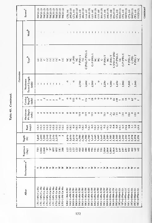
"u * •— ? -- ? "- * w^w^w^^^^^w^w^^^^-3 OOOOOOOOO "O'O^O^ o-:o~o~o~o~o~o~o"ouuuuuuuuu H u J u J u H oHuJuHuJuHuHuJu-JuCO zzzzzzzzz W 7 W y W 7 HI
(J — U S (J — U _(J — U — U — <J — USU — U — US
Cv1
1 1 1 1 1 1 1 1 1 1 1 1 1 1 1 1
s
H
NC NC(PR)
NCPR);T
I-C
;P(PR)
H B! (- f-
-Cl^ S- H -gj" ^ ^ t-„f-
a.>-
VVuVVVVcuV-— ^ ^ a, -c a, o w ^ w cl.0- 1-1
H u- i
a. ^ wtfo- a- wijwa. a. * ' - a &<
QLi o -o oo
co
toV E &
1 S ~ O O O O oooooooo6 -> - iO, .m.Oim.OiO.O,
1 1 1 1 1 1 1 1 1 11 l^ 1 o 1 x I IcmIoInIoIoIoI
s is e (N rvf (S <N ^ t-h* tH ci ms 1"H
m o O O in O O ui m-^OOwtOOOrNON ^Hr^OtNO(N \00«fS^HvO-H
£ g-e r-l rH rt
u a -
E £1 8-2 OOOOOOOOO O O O O >n O ui OmOOOu-.Oi^<sinOu-iOmOi^iO
-H _| TH \0 *-< 1-1 iH iH
S £w
OOOOOOOOO O O O O O O O OOOOOOOOOOOOOO^rtOOS j= vvvvvvvvv V V V V VVVVV VV V
OOOOOOOmu-i o o o o o o o OOOOOOOOOOOOOOOOO* O O * * 1- t> + -t + -J- 00 00 CO w*'j-'+"*-oooo**Tt-Tj-r^t>t~t»
a"'
*0 m m m m m m o >o <> ^0 r^ r^ r^ r^^O^GtG^Orrtrrirrirrtrrir^rrirrimrrtmmm tr, u-, ir, \0 O •& Ointnmir>i/">mi^ir)<N<NrN(NcN(N<N«N
3 -T-^-H^-Tt-r^t^rsfN^Hxo m ~ -~ ~ ^ -t ~t- -t -f- r- [^ r^ r^ n ^) rj r\U1\0^00\0\OOX\0 (N cs fS (N O O O Oi^i»nmuivO^O<5voONO\ONOsOOOO
O M C^OO^r-Tt-Tt-rtro _ rt -1 ~H *)- •* Tj- ^-r^r~t^r^oOOO'-i^H^»-<Tt--^-*3*Tha. tiX —
'
rt th" -<" rt" -h" rt
at
«3
sEco
C/}^CO^CO^C/)^^ ^ S O f> S S !/l C^^Sc/lOOSSoDl/lgStOcSSc/ll/)
c
OOOOOOOOOo
5
SSSSSSSSS333333333uuuuuOOuuz z z z z z z zzzzzzzzzzzzzzzzzo o o o o o o OOOOOOOOOOOOOOOOOa c c g c a cS S £ S S S S
cccccncccccccccacssssssssssssssssszzzzzzzzz**t**i-T)-Tt-Tf<tTt- * * * Tj- Tj- ^t- Tl" ****Tt-Tt-^-Tf-T)-Tl-Tl-'*^-Tt-^t--!}-T}-
iti.i.i.J.i.i,i.i.iii.ii,i,iUUCJUUUUUU u u u o u o u uuuucjuuuuuuuuuuuut^r^-t^r^t^r^r^r^t^ CO 00 00 00 00 CO 00 xxxxxxxxxxxxxxxxx
172

« 1c -*
e £
I £w
ai £
nt E At-
X v5 x
Cc
h D
a
5
s s
3 "
oa bi
-a j3
Si! Su
a. V Q !il U.1
5. > 3CoZ
c
x 82 c- ii II ll II II n ii ii ii
>, 5 NM C <" u U>
o P o u Own. X - 2 z a.
173
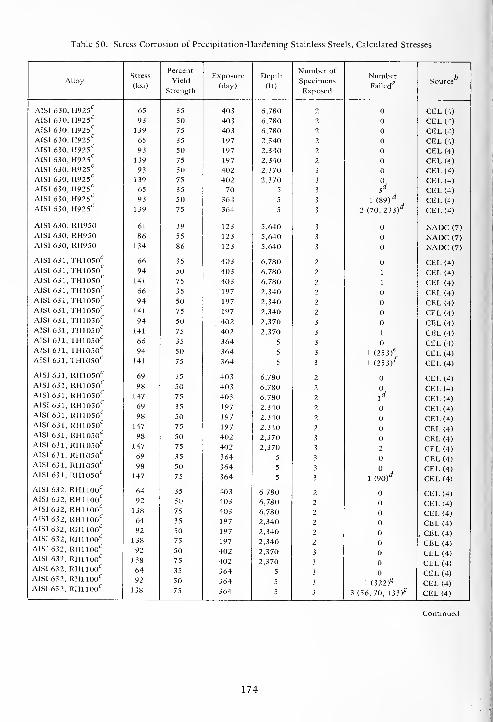
Table 50. Stress Corrosion of Precipitation-Hardening Stainless Steels, Calculated Stresses
Percent Number ofStress Exposure Depth Number bAlloy(ksi)
Yield
Strength(day) (ft)
Specimens
ExposedFailed
Source
AISI 630, H925c65 35 403 6,780 2 CEL (4)
AISI 630, H925 c93 50 403 6,780 2 CEL (4)
AISI 630, H925C
139 75 403 6,780 2 CEL (4)
AISI 630, H925C
65 35 197 2,340 2 CEL (4)
AISI 630, H925C
93 50 197 2,340 2 CEL (4)
AISI 630, H925C
139 75 197 2,340 2 CEL (4)
AISI 630, H925C
93 50 402 2,370 3 CEL (4)
AISI 630, H925C
139 75 402 2,370 3 CEL (4)
AISI 630, H925C
65 35 70 5 3 id CEL (4)
AISI 630, H925C
93 50 364 5 3 1 (89)d CEL (4)
AISI 630, H925C
139 75 364 5 3 2 (70, 233)rf CEL (4)
AISI 630, RH950 61 39 123 5,640 3 NADC (7)
AISI 630, RH950 86 55 123 5,640 3 NADC (7)
AISI 630, RH950 134 86 123 5,640 3 NADC (7)
AISI 631,TH1050C66 35 403 6,780 2 CEL (4)
AISI 631,TH1050C
94 50 403 6,780 2 1 CEL (4)AISI 631, TH1050
C141 75 403 6,780 2 1 CEL (4)
AISI 631, TH1050C
66 35 197 2,340 2 CEL (4)AISI 631, TH1050
C94 50 197 2,340 2 CEL (4)
AISI 631,TH1050C
141 75 197 2,340 2 CEL (4)AISI 631,TH1050C
94 50 402 2,370 3 CEL (4)AISI 631,TH1050C
141 75 402 2,370 3 1 CEL (4)AISI 631,TH1050C
66 35 364 5 3 CEL (4)AISI 631, TH1050C 94 50 364 5 3 1 (2Sif CEL (4)AISI 631,TH1050C
141 75 364 5 3 1 (253/ CEL (4)
AISI 631, RH1050C69 35 403 6,780 2 CEL (4)
AISI 631, RH1050C
98 50 403 6,780 ? CEL (4)AISI 631, RH1050
C147 75 403 6,780 2 l
dCEL (4)
AISI 631, RH1050C
69 35 197 2,340 2 CEL (4)AISI 631, RHIOSO^ 98 50 197 2,340 2 CEL (4)AISI 631, RH1050C
147 75 197 2,340 2 CEL (4)AISI 631, RH1050C 98 50 402 2,370 3 CEL (4)AISI 631, RH10S0C
147 75 402 2,370 3 2 CEL (4)AISI 631, RH1050C
69 35 364 5 3 CEL (4)AISI 631, RH1050C
98 50 364 5 3 CEL (4)AISI 631, RH1050C
147 75 364 5 3 1 (90)d CEL (4)
AISI 632, RH1100C64 35 403 6,780 2 CEL (4)
AISI 632, RH1100C
92 50 403 6,780 2 CEL (4)AISI 632, RH1100C
138 75 403 6,780 2 CEL (4)AISI 632, RH1100C
64 35 197 2,340 2 CEL (4)AISI 632, RH1100C
AISI 632, RHllOO 17
92
138
50
75
197
197
2,340
2,340
2
2
, CEL (4)
CEL (4)AISI 632, RH1100C
92 50 402 2,370 3 CEL (4)AISI 632, RHllOO^ 138 75 402 2,370 3 CEL (4)AISI 632, RH1100C
64 35 364 5 3 CEL (4)AISI 632, RH1100C
92 50 364 5 3 1 (322)£ CEL (4)AISI 632, RH1100C
138 75 364 5 3 3 (56, 70, 133)^ CEL (4)
174

Table 50. Continued.
Percent Number ofStress Exposure Depth Number b
Alloy Yield Specimens Source(ksi)
Strength(day) (ft)
ExposedFailed
A1SI 634, CRT 108 50 402 2,370 3 CEL(4)AISI 634, CRT 162 75 402 2,370 3 CEL (4)
AISI 635 68 35 197 2,340 3 CEL(4)AISI 635 97 50 197 2,340 3 CEL (4)
AISI 635 145 75 197 2,340 3 CEL (4)
AISI 635 92 50 402 2,370 3 CEL (4)
AISI 635 138 75 402 2,370 3 CEL (4)
ASTMXM16, H950 - 75 189 5,900 2 CEL (4)
ASTMXM16, H1050ASTMXM16, H1050*
- 75 189 5,900 1 CEL (4)- 75 189 5,900 1 CEL (4)
PH14-8MO, SRH950C75 35 403 6,780 2 CEL (4)
PH14-8MO, SRH950C
107 50 403 6,780 2 CEL (4)
PH14-8MO, SRHPSO*7
161 75 403 6,780 2 1 CEL (4)
PH14-8MO, SRH950C
75 35 197 2,340 2 CEL (4)
PH14-8MO, SRH950C
107 50 197 2,340 2 CEL (4)
PH14-8MO, SRH950C
161 75 197 2,340 2 CEL (4)
PH14-8MO, SRH950C
107 50 402 . 2,370 3 1 CEL (4)
PH14-8MO, SRH950C161 75 402 2,370 3 1 CEL (4)
PH14-8MO, SRH950C75 35 364 5 3 3 (322)
d CEL (4)PH14-8MO, SRH950 <:
107 50 364 5 3 3 (322)^ CEL (4)
PH14-8MO, SRH950C161 75 364 5 3 CEL (4)
15-7 AMV, A 20 35 403 6,780 2 CEL (4)15-7 AMV, A 29 50 403 6,780 2 CEL (4)15-7 AMV, A 43 75 403 6,780 2 1 CEL (4)
1 5-7 AMV, A 20 35 197 2,340 3 CEL (4)15-7 AMV, A 29 50 197 2,340 3 CEL (4)15-7 AMV, A 43 75 197 2,340 3 CEL (4)15-7 AMV, A 29 50 402 2,370 3 CEL (4)15-7 AMV, A 43 75 402 2,370 3 CEL (4)
15-7 AMV, RH1150 55 35 123 5,640 3 CEL (4)15-7 AMV, RH1150 79 50 123 5,640 3 CEL (4)15-7 AMV, RH1150 119 75 123 5,640 3 CEL (4)15-7 AMV, RH1150 55 35 403 6,780 2 CEL (4)15-7 AMV, RH1150 79 50 403 6,780 2 CEL (4)15-7 AMV, RH1150 119 75 403 6,780 2 CEL (4)15-7 AMV, RH1150 55 35 751 5,640 3 3' CEL (4)15-7 AMV, RH1150 79 50 751 5,640 3 l[ CEL (4)15-7 AMV, RH1150 119 75 751 5,640 3 3' CEL (4)15-7 AMV, RH1150 79 50 197 2,340 3 2 CEL (4)15-7 AMV, RH1150 119 75 197 2,340 3 3 CEL (4)15-7 AMV, RH1150 79 50 402 2,370 3 1 CEL (4)15-7 AMV, RH1150 119 75 402 2,370 3 1 CEL (4)
15-7 AMV, RH950 77 35 123 5,640 3 1> CEL (4)15-7 AMV, RH950 110 50 123 5,640 3 3, CEL (4)15-7 AMV, RH950 165 75 123 5,640 3 3
kCEL (4)
15-7 AMV, RH950 77 35 403 6,780 2 CEL (4)15-7 AMV, RH950 110 50 403 6,780 2 CEL (4)15-7 AMV, RH950 165 75 403 6,780 2 2 CEL (4)
175
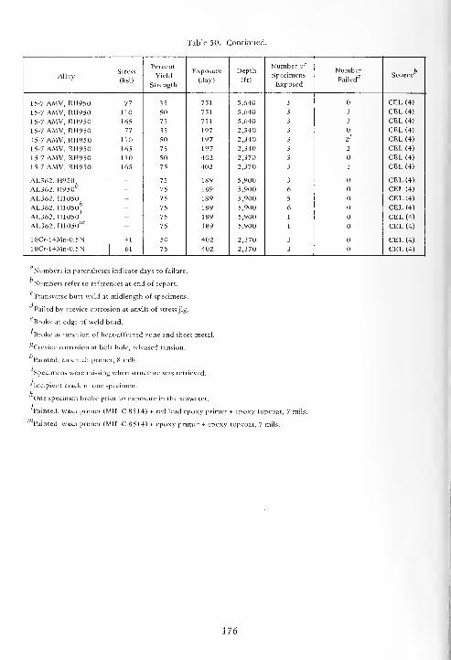
Table 50. Continued.
AlloyStress
(ksi)
Percent
Yield
Strength
Exposure
(day)
Depth
(ft)
Number of
Specimens
Exposed
NumberFailed
Source
15-7 AMV, RH950 77 35 751 5,640 3 CEL (4)
15-7 AMV, RH950 110 50 751 5,640 3 3 CEL (4)
15-7 AMV, RH950 165 75 751 5,640 3 3 CEL (4)
15-7 AMV, RH950 77 35 197 2,340 3 CEL (4)
15-7 AMV, RH950 110 50 197 2,340 3 2> CEL (4)
15-7 AMV, RH950 165 75 197 2,340 3 2 CEL (4)
15-7 AMV, RH950 110 50 402 2,370 3 CEL (4)
15-7 AMV, RH950 165 75 402 2,370 3 3 CEL (4)
AL362, H950AL362, H950
- 75 189 5,900 3 CEL (4)
- 75 189 5,900 6 CEL (4)
AL362, H1050AL362, H1050
/:>
- 75 189 5,900 5 CEL (4)
- 75 189 5,900 6 CEL (4)
AL362, H1050' - 75 189 5,900 1 CEL (4)
AL362, H1050'" - 75 189 5,900 1 CEL (4)
18Cr-14Mn-0.5N 41 50 402 2,370 3 CEL (4)
18Cr-14Mn-0.5N 61 75 402 2,370 3 CEL (4)
Numbers in parentheses indicate days to failure.
Numbers refer to references at end of report.
Transverse butt weld at midlength of specimens.
Failed by crevice corrosion at anvils of stress jig.
Broke at edge of weld bead.
f' Broke at junction of heat-affected zone and sheet metal.
*Crevice corrosion at bolt hole, released tension.
Painted, zinc-rich primer, 8 mils.
Specimens were missing when structure was retrieved.
•'Incipient crack in one specimen.
kOne specimen broke prior to exposure in the seawater.
Painted, wash primer (MIL-C-8514) + red lead epoxy primer + epoxy topcoat, 7 mils.
Painted, wash primer (MIL-C-8514) + epoxy primer + epoxy topcoat, 7 mils.
176

co o 73
.S <-;
c "O " C
cO.
o
73
a73 i-
.2 Sa. dO ui- X)
D. 73O 4J
- <a-a u-,
XI rt
2 x:u e£ -5
73 73
73 o
x>
-ac3
o -°
B..S
S 3° E
O 00
n.'S
<L> 73
^73
s %73
Co
o
3X)U73
OC
3XIaj
73
OC
J2
2co
o 2 X>
1 22 '2 »4-i 73
O 7£J V
| 1 1-oc
*"g S o(+-. 73 73 73 c
ox:
"3
Oi "o g O c <u c 73 73
o 73o ."2 u 1 §
QJ 373 g
1) 373 O XI
1 lu
1 ao
£ o 5J
-o_c
-a § s o 1 S I 3tr
c3
c3
rtc OJ C N
d *-» o
S 'O c «4_, ^j
00
D._>N 00
O 73 —c M —.3 " U
O o O oo
a)
C
-5D.O .5? o 5 00 u N
'C .tj -a^m ^g .S3 73
373
!sp '3l
cr- aa. O £ 73 o -a u o -£ o o
ibu 3
Uu S 2
o" -5 u U u uU U U o SB u c
C/3 .5 S.Su o u
oo OO XI oo CO x: rt C/3 XI rt oo oo 00
73 -a -a 73 -a 73 T3
U u OJ <D u OJ
£ & 5 £ s & S S o o "ooo xi XI— rt J2 J2 — -5 _rt ^2 JS 73 733 3 3 3 3 "3 3 3 u 1U
u CJ73 3
<Du CJ ° u u °
>^ 73 73
« -o 73 73 -a -a 73 73 XI 73 73<u U <U OJ u OJ
> > > 73I Bo 1) U u U u
OOJ <U U u OJ OJ UCu n.
c C C c c c c g c CE- D 3 3 D D D D D 13
XS o o o o o o o o ooo oo <t t^ 00 r- ^r o or^ t^ m ro r^ fr* \q "1 "1
Q MD no" (N <N no" (N ir> u-i in
uoo t^ (N rr\ (N d- ^f
3> ">. O ON o On O O o IN no \oO rt ^1- * * * * O oD. 73x — rn" ^n"
w
o oo o O o O oo £ rt
oir>
o o O o o On
BC I aso\ X X 3C X X BC OS BJ A
^T" X i- H tti <& ai oi— „ n . K > > >< o
J^ £ r«-» rn s M sno o no no vO NO xO <C < <c
t^ t>. t>>in 00 oo 00 CO C/3 C/)
< < < < < < < 1—1 T_l ^H
177
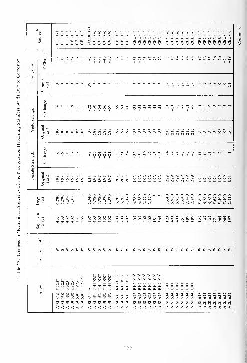
-Q r^
+ * + + + + uJJJJ -f Tf -f *i- Tf Tj- Tf Tf Tf Tf Tf Tf Tf T* if Tf Tf Tf -f Tf Tf -f
3 j j j j j j D J J J -4 J -J J J J J J W W J J W J J J J J J -J J J Jx < U U MM www w w w w w w w w w w w w w w w w w w w
u <j u u u u z u u u u U U (J U <J U nJ u u U <J U U U U V V u u u u u
m t~- t^ o r- t^ ON t^ -h N + + t i- r^ (N fo no no Tf xro Tf Tf + r~ I-~ l + + + + + + Ifl m N CN^ N H
I I I I ' + + + + + + + + + 1 1 1 1 1 1
O U
CO _w c
O
t^ ro m rr, rr, On ON On ON On ON Tf -f Tf Tf On ON Tf
1 M O + * S ON Tf O m Tf in Tf Tf Tf
c u I I
(S no in in u-i in in noI ,
tH H H + + + ++ + +
V3
TO
> r^ c^ t^ Tf Tf Tf Tf rn m TfCO X 00 CO 00 CO in oo co oo oo ON On On X CO X 00 00 00
N <N1 <M (N <N <N1X X X X ON ON X
o
£ c no on x r-~ r^ 00 in Tf <s i-i ON th Tf (N it o ON in m if + -t X m rr, H N H to M t H
Si #x
'35 —c m (VI f\l N rl rM (N -t r^ t-v t^ r^ t^ r^ t^ M rH N N N N On On On On On On rt t-i -h H On ON ri
.2P -SOn ON On ON On ON m On ON On On o o o ON ON ON On On On ON ON ON ON ON On ON
O
o o o O O O O m in O O O O O O o o o o o o oX X t^ t-^ Tf X X Tf Tf Tf Tf X X Tf O O Tf
Ca~ ^ ^ m
. "INO NO (Nl (N)
rn t-v t^ m m t-- t^ m [^ t-- rr, rr, no t> t-- no rr, rn mC*l NO NO IN <N no no N NO NO <v] r*l in no no in N cn) in no no in in in cn!
3 -* m ro (s cs r-i in m m rn ^h r^ r^ rr, m m w Tf Tf I--
On O O O O o o o o o o o x no <ni O O m On On tN O O m no no Ont * Tf Tf •+ * Tf Tf -t Tf Tf * -< rr, t-. ^f Tf f- ri rt h Tf Tf f^ O O <H
2. T3 ^H rt
ta
sEc S «S »! J J 5 5 X ^ X 5 CO ^ ^ CO ^ CO ^ ^ J J u) S 5 u) ^ ^ X 5 ^ X 5
a
tj o o o o o o o o oU U U U U. if o o o
o o o o o o!- t- f- f- t- S-
ON ON ON ON ON ON I I I I XXX X I I I I I os as as as os as
<i x x x x x < S- S- H S- X as as OS as X X X oi u u u u u u
„ m ^, „ ^ ^ ^NO NO ^O NO ^o no NO NO NO NO NO NO NO NO NO NO NO NO NO NO no no no no no NO ^O *C *0 ^O *C 'O ^O
X X X X X X CO CD CO CO CO CO CO CO CO CO CO X CO CO X X X X X X t/1 73 C/l (/3 C/) W i/)
<<<<<< < < < < < < < < <<<<<< <<<<<< <<<<<<<
178
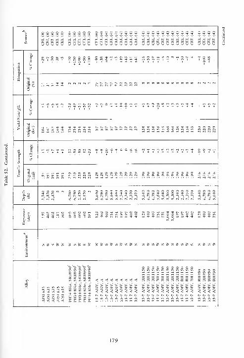
Tl-Tj-^-^-T|--+Tt-J--* *•**+J J -J J J -JId El Id Id Id _ _ tti W _yuucju 'O u u u u
_j _ jjjjjjjjj ___________
OOOOO O oo + NOOf-^^t-O"! —i o
OO'-'^ —i r^ on » x
x x x x xXXXXnonoxXXX oooo
Tf O O X X
ON On CN On On ONOnOnOnOnONONOnOn 00000--0000 XXXXM rj N M N MNNMWNNNN OnOnOnOnOnOnOnOnOnCnCn ^-^-^--t"
ooooo ocooooooooo ooooX •* rt- t •* 'i-xX'+'toO't^-t^r^ -1- x x +
_ t^ t^ NO _ \0 t^ t^- o
On O C X-j-^h —
,-j- -j- r~ t^ .- .-« --< ^t- <3- r^ r^
x ^ x S JJ«i^i«iioJ»i „^t/i^i/)S(flSinJin x ^ X 5
OOOOOC\ On On On On
<<<<<<<<<
OOOOOOOOOOOi/l-.inu-iinininininini/> OOOO—iT-Hr-<<-H—I—l.-H^^.-H—I ONOnOnON__________x x___:__e:_(__;:_asos_« _ a: ai oi
S 2 3 3 SX 00 X X X+ + 4 + -t
x x x x x zZ _ _ — —no no _ no NO
>>>>>>>>>SSSSSSSSS<<<<<<<<<> > > >S S S 5
f* -• r*. r>
>>>>>>S S S < S S
< <r~ r*. r*.
> > > >
<! < < <
179

-a
3o J J J _I JJ_J_JJJ.JJ.JJJ
Id HI U U uidUUidldUttiuiiiiiiu <j <_> u uuuuuuuuuuu
co
coW
60CO 00 <N 00 <JmHnM^*O-tNH0\
1 1 1 l i i
.S '-
o~ N N N N NNMNNNfSMWNN
>
x:O N N h mvocsinrt^rtinmmro
+ + + i + + + + +m + + + +
'5p j£ CN(M(N(N CO00COXX00O000OOO0O0
Soc
c
H
60
u
m N M N OCSOO^rSt^fN^Hr-H^H
.S'-'
6~
CO 00 00 CO "O^O^O^OsOSO^O^OvOO^O
oooo oooooooooooN N (N M «^>OCintfl«^NNM(N
ha. -ox —
ON C\ O O (NOO^UIO^OONOvOO
1
'>
w
S on & t/> tnStoSin^mJtnJm
<
oooo£ £ £ oj ZZZZ222Z2ZZoi _; _; oi o o o o' d d o' o' o' d o'
>>>> SSSSSSSSSSSvr ^ v> ^ uuuuuuuuuuumtninin Xoooocoooooooxcooooo
o -a
s _
S 1
O — •-
£ 5 Z
180

Table 53. Chemical Compositions of Miscellaneous Stainless Steels, Percent by Weight
Alloy C Mn P S Si Ni Cr Mo Cu Other Fe c bSource
20 Cb 0.04 0.79 0.018 0.004 0.67 28.38 19.80 2.06 3.11 0.77 Cb + Ta R CEL (4)
20 Cb 0.05 0.82 - - 0.70 28.43 20.09 2.32 3.37 0.83 Cb + Ta R CEL (4)
20 Cb - - - - " 33.0 20.0 2.5 3.5 - R INCO (3)
20 Cb-3C
0.07 2.0 0.035 0.035 1.0 34.0 20.0 2.5 3.5 Cb + Ta, 8XC R CEL (4)
20Cb-3 - - - - - 34.0 20.0 2.3 3.4 - R INCO (3)
Ni-Cr-Cu-Mo No. 1, cast - - - - - 30.0 20.0 2.5 4.0 - R INCO (3)
Ni-Cr-Cu-Mo No. 2, cast - - - - - 30.0 20.0 2.5 3.5 - R INCO (3)
Ni-Cr-Mo, cast - - - - - 24.0 19.0 3.0 - - R INCO (3)
Ni-Cr-Mo-Si, cast - - - - 1.0 23.0 21.0 5.0 - - R INCO (3)
RL-3 5-100, cast " 1.0 - - 31.0 23.0 9.0 - - R INCO (3)
R = remainder.
Numbers refer to references at end of report.
Typical analysis.
Table 54. Corrosion Rates and Types of Corrosion of Miscellaneous Stainless Steels
Alloy EnvironmentExposure
(day)
Depth
(ft)
Corrosion
SourceRate
(mpy)
MaximumPit Depth
(mils)
Crevice
Depth*
(mils)
Type*
20 Cb W 123 5,640 NC CEL (4)
20 Cb S 123 5,640 NC CEL (4)
20 Cb W 403 6,780 NC CEL (4)
20 Cb S 403 6,780 <0.1 102 C CEL (4)
20 Cb W 751 5,640 <0.1 26 c CEL (4)
20 Cb S 751 5,640 NC CEL (4)
20 Cb W 1,064 5,300 NC CEL (4)
20 Cb S 1,064 5,300 NC CEL (4)
20 Cb W 197 2,340 <0.1 I 1-C CEL (4)
20 Cb S 197 2,340 <0.1 1 I-C CEL (4)
20 Cb w 402 2,370 <0.1 NC CEL (4)
20 Cb s 402 2,370 <0.1 NC CEL (4)
20 Cb w 181 5 <0.1 5 C;SL-E CEL (4)
20 Cb w 398 5 <0.1 14 SL-E; P CEL (4)
20 Cb w 540 5 <0.1 24 P CEL (4)
20 Cb w 588 5 <0.1 21 C CEL (4)
20 Cb-3 w 123 5,640 <0.1 NC INCO (3)
20 Cb-3 s 123 5,640 <0.1 NC INCO (3)
20 Cb-3 w 189 5,900 <0.1 I I l-C; 1-P CEL (4)
20 Cb-3 s 189 5,900 <0.1 40 C CEL (4)
181
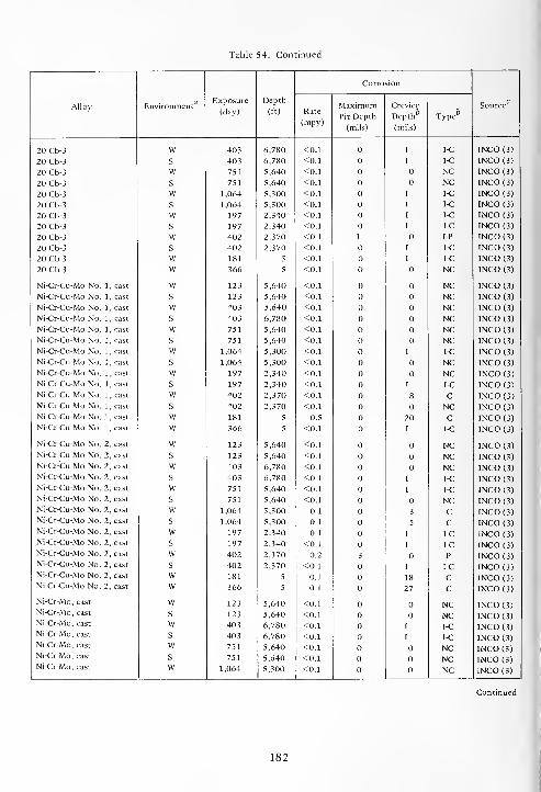
Table 54. Continued.
Alloy EnvironmentExposure Depth
Corrosion
SourceMaximum Crevice(day) (ft) Rate
(mpy)Pit Depth
(mils)
Depth6
(mils)
Type
20 Cb-3 W 403 6,780 <0.1 1 I-C INCO (3)
20 Cb-3 S 403 6,780 <0.1 I I-C INCO (3)
20 Cb-3 W 751 5,640 <0.1 NC INCO (3)
20 Cb-3 S 751 5,640 <0.1 NC INCO (3)
20 Cb-3 W 1,064 5,300 <0.1 I I-C INCO (3)
20 Cb-3 s 1,064 5,300 <0.1 I I-C INCO (3)
20 Cb-3 w 197 2,340 <0.1 1 I-C INCO (3)
20 Cb-3 s 197 2,340 <0.1 1 I-C INCO (3)
20 Cb-3 w 402 2,370 <0.1 1 IP INCO (3)
20 Cb-3 s 402 2,370 <0.1 I I-C INCO (3)
20 Cb-3 w 181 5 <0.1 1 1-C INCO (3)
20 Cb-3 w 366 5 <0.1 NC INCO (3)
Ni-Cr-Cu-Mo No. 1 , cast w 123 5,640 <0.1 NC INCO (3)
Ni-Cr-Cu-Mo No. 1, cast s 123 5,640 <0.1 NC INCO (3)
Ni-Cr-Cu-Mo No. 1, cast w 403 5,640 <0.1 NC INCO (3)
Ni-Cr-Cu-Mo No. 1, cast s 403 6,780 <0.1 NC INCO (3)
Ni-Cr-Cu-Mo No. 1, cast w 751 5,640 <0.1 NC INCO (3)
Ni-Cr-Cu-Mo No. 1, cast s 751 5,640 <0.1 NC INCO (3)
Ni-Cr-Cu-Mo No. 1, cast w 1,064 5,300 <0.1 I I-C INCO (3)
Ni-Cr-Cu-Mo No. 1, cast s 1,064 5,300 <0.1 NC INCO (3)
Ni-Cr-Cu-Mo No. 1, cast w 197 2,340 <0.1 NC INCO (3)
Ni-Cr-Cu-Mo No. 1, cast s 197 2,340 <0.1 I I-C INCO (3)
Ni-Cr-Cu-Mo No. 1, cast w 402 2,370 <0.1 8 c INCO (3)
Ni-Cr-Cu-Mo No. 1 , cast s 402 2,370 <0.1 NC INCO (3)
Ni-Cr-Cu-Mo No. 1, cast w 181 5 0.5 20 c INCO (3)
Ni-Cr-Cu-Mo No. 1, cast w 366 5 <0.1 I I-C INCO (3)
Ni-Cr-Cu-Mo No. 2, cast w 123 5,640 <0.1 NC INCO (3)
Ni-Cr-Cu-Mo No. 2, cast s 123 5,640 <0.1 NC INCO (3)
Ni-Cr-Cu-Mo No. 2, cast w 403 6,780 <0.1 NC INCO (3)
Ni-Cr-Cu-Mo No. 2, cast s 403 6,780 <0.1 I I-C INCO (3)Ni-Cr-Cu-Mo No. 2, cast w 751 5,640 <0.1 I I-C INCO (3)Ni-Cr-Cu-Mo No. 2, cast s 751 5,640 <0.1 NC INCO (3)Ni-Cr-Cu-Mo No. 2, cast w 1,064 5,300 0.1 3 C INCO (3)Ni-Cr-Cu-Mo No. 2, cast s 1,064 5,300 0.1 5 C INCO (3)Ni-Cr-Cu-Mo No. 2, cast w 197 2,340 0.1 I I-C INCO (3)Ni-Cr-Cu-Mo No. 2, cast s 197 2,340 <0.1 I I-C INCO (3)Ni-Cr-Cu-Mo No. 2, cast w 402 2,370 0.2 3 p INCO (3)Ni-Cr-Cu-Mo No. 2, cast s 402 2,370 <0.1 1 I-C INCO (3)Ni-Cr-Cu-Mo No. 2, cast w 181 5 0.1 18 c INCO (3)Ni-Cr-Cu-Mo No. 2, cast w 366 5 0.1 27 c INCO (3)
Ni-Cr-Mo, cast w 123 5,640 <0.1 NC INCO (3)Ni-Cr-Mo, cast s 123 5,640 <0.1 NC INCO (3)Ni-Cr-Mo, cast w 403 6,780 <0.1 I I-C INCO (3)Ni-Cr-Mo, cast s 403 6,780 <0.1 1 I-C INCO (3)Ni-Cr-Mo, cast w 751 5,640 <0.1 NC INCO (3)Ni-Cr-Mo, cast s 751 5,640 <0.1 NC INCO (3)Ni-Cr-Mo, cast w 1,064 5,300 <0.1 NC INCO (3)
182

Table 54. Continued.
Alloy Environment'Exposure Depth
Corrosion
SourceMaximum Crevice(day) (ft) Rate
(mpy)Pit Depth
(mils)
Depth^
(mils)
_ bType
Ni-Cr-Mo, cast S 1,064 5,300 <0.1 NC INCO (3)
Ni-Cr-Mo, cast W 197 2,340 <0.1 NC INCO (3)
Ni-Cr-Mo, cast S 197 2,340 <0.1 I I-C INCO (3)
Ni-Cr-Mo, cast W 402 2,370 <0.1 I 1-C INCO (3)
Ni-Cr-Mo, cast S 402 2,370 <0.1 I I-C INCO (3)
Ni-Cr-Mo, cast W 181 5 <0.1 NC INCO (3)
Ni-Cr-Mo, cast w 366 5 <0.1 NC INCO (3)
Ni-Cr-Mo-Si, cast w 123 5,640 <0.1 NC INCO (3)
Ni-Cr-Mo-Si, cast s 123 5,640 <0.1 NC INCO (3)
Ni-Cr-Mo-Si, cast w 403 6,780 <0.1 NC INCO (3)
Ni-Cr-Mo-Si, cast s 403 6,780 <0.1 NC INCO (3)
Ni-Cr-Mo-Si, cast w 751 5,640 <0.1 NC INCO (3)
Ni-Cr-Mo-Si, cast s 751 5,640 <0.1 NC INCO (3)
Ni-Cr-Mo-Si, cast w 1,064 5,300 <0.1 NC INCO (3)
Ni-Cr-Mo-Si, cast s 1,064 5,300 <0.1 NC INCO (3)
Ni-Cr-Mo-Si, cast w 197 2,340 <0.1 NC INCO (3)
Ni-Cr-Mo-Si, cast s 197 2,340 <0.1 NC INCO (3)
Ni-Cr-Mo-Si, cast w 402 2,370 <0.1 NC INCO (3)
Ni-Cr-Mo-Si, cast s 402 2,370 <0.1 NC INCO (3)
Ni-Cr-Mo-Si, cast w 181 5 <0.1 NC INCO (3)
Ni-Cr-Mo-Si, cast s 366 5 <0.1 NC INCO (3)
RL-35-100, cast w 123 5,640 0.3 G INCO (3)RL-35-100, cast s 123 5,640 0.5 G INCO (3)RL-35-100, cast w 403 6,780 <0.1 G INCO (3)RL-35-100, cast s 403 6,780 0.3 G INCO (3)RL-35-100, cast w 751 5,640 <0.1 U-ET INCO (3)RL-35-100, cast s 751 5,640 0.3 ET INCO (3)RL-35-100, cast w 1,064 5,300 0.7 G INCO (3)RL-35-100, cast s 1,064 5,300 0.1 G INCO (3)RL-35-100, cast w 197 2,340 <0.1 NC INCO (3)RL-35-100, cast s 197 2,340 <0.1 NU-ET INCO (3)
W - Totally exposed in seawater on sides of structure; S = Exposed in base of structure so that the lower portions of the specimewere embedded in the bottom sediments.
Symbols for types of corrosion:
C = Crevice NC = No visible corrosion
E = Edge NU = NonuniformET = Etched P = Pitted
G = General SL = Slight
1 = Incipient U = Uniform
Numbers refer to references at end of report.
183
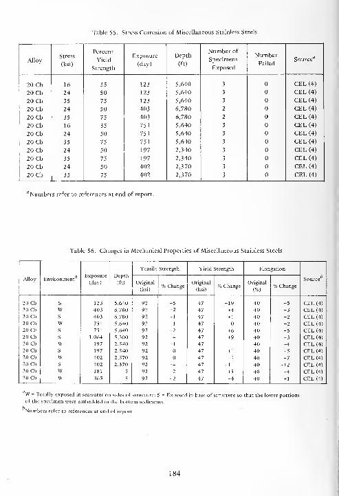
Table 55. Stress Corrosion of Miscellaneous Stainless Steels
AlloyStress
(ksi)
Percent
Yield
Strength
Exposure
(day)
Depth
(ft)
Number of
Specimens
Exposed
NumberFailed
Source"
20 Cb 16 35 123 5,640 3 CEL (4)
20 Cb 24 50 123 5,640 3 CEL (4)
20 Cb 35 75 123 5,640 3 CEL (4)
20 Cb 24 50 403 6,780 2 CEL (4)
20 Cb 35 75 403 6,780 2 CEL (4)
20 Cb 16 35 751 5,640 3 CEL (4)
20 Cb 24 50 751 5,640 3 CEL (4)
20 Cb 35 75 751 5,640 3 CEL (4)
20 Cb 24 50 197 2,340 3 CEL (4)
20 Cb 35 75 197 2,340 3 CEL (4)
20 Cb 24 50 402 2,370 3 CEL (4)
20 Cb 35 75 402 2,370 3 CEL (4)
"Numbers refer to references at end of report.
Table 56. Changes in Mechanical Properties of Miscellaneous Stainless Steels
Alloy EnvironmentExposure
(day)
Depth
(ft)
Tensile Strength Yield Strength Elongation
c bSource
Original
(ksi)% Change
Original
(ksi)% Change
Original
(%)% Change
20 Cb
20 Cb
20 Cb20 Cb20 Cb20 Cb20 Cb
20 Cb20 Cb20 Cb20 Cb20 Cb
S
WS
WS
S
WS
WS
WW
123
403
403
751
751
1,064
197
197
402
402
181
365
5,640
6,780
6,780
5,640
5,640
5,300
2,340
2,340
2,370
2,370
5
5
92
92
92
92
92
92
92
92
92
92
92
92
+5
+2
+ 1
+ 1
+2
+4
-1
+4
+2
-2
47
47
47
47
47
47
47
47
47
47
47
47
+ 19
+4
+ 1
+6
+9
-1
+ 1
-1
+ 11
+5
-4
40
40
40
40
40
40
40
40
40
40
40
40
-5
-3
-2
-2
-5
-3
+4
-5
-7
-12
-4
+ 1
CEL (4)
CEL (4)
CEL (4)
CEL (4)
CEL (4)
CEL (4)
CEL (4)
CEL (4)
CEL (4)
CEL (4)
CEL (4)
CEL (4)
W = Totally exposed in seawater on sides of structure; S = Exposed in base of structure so that the lower portions
of the specimen were embedded in the bottom sediments.
Numbers refer to references at end of report.
184

SECTION 6
ALUMINUM ALLOYS
The resistance of aluminum and its alloys to cor-
rosion is due to a relatively chemically inert film of
aluminum oxide which forms on its surface. As long
as this oxide film remains intact the good corrosion
resistance is preserved. In oxidizing environments
where a sufficient amount of oxidizing agent or
oxygen is present to repair any breaks in this protec-
tive film, the corrosion resistance of the aluminum
alloys is maintained. The usual corrosion protection
(passive) film that forms on aluminum in waters at
temperatures below 70°C is bayerite
(j3-Al2 3-3H 2 0).
In general, oxidizing conditions favor the pre-
servation of this passive film, while reducing condi-
tions destroy it. Chloride ions are particularly
agressive in destroying this passive film.
When aluminum is immersed in water, the oxide
film thickens much more rapidly than it does in air.
The rate of growth decreases with time and reaches a
limiting thickness which depends on the temperature,
the oxygen content of the water, the ions present,
and the pH. In seawater this naturally formed protec-
tive film breaks down more readily, and its repair and
growth are retarded by the chloride ion.
The corrosion of aluminum alloys in seawater is
usually of the pitting and crevice types. Pits begin by
breakdown of the protective film at weak spots or at
nonhomogeneities. The breakdown is followed by the
formation of an electrolytic cell, the anode of which
is a minute area of active metal and the cathode of
which is a considerable area of passive metal. The
large potential difference of this "passive-active" cell
accounts for the considerable flow of current with its
attendant rapid corrosion at the small anode (pitting).
Pitting is most likely to occur in the presence of
chloride ions (for example, in seawater), combined
with such cathodic depolarizers as oxygen or
oxidizing salts. An oxidizing environment is usually
necessary for preservation of a passive protective film
with accompanying high corrosion resistance, but,
unfortunately, it is also a condition for the
occurrence of pitting. The oxidizer can often act as a
depolarizer for "passive-active" cells established by
the breakdown of passivity at a specific point or area.
The chloride ion in particular can accomplish this
breakdown.
As discussed above, aluminum alloys generally
corrode in seawater by pitting and crevice corrosion;
therefore, as much as 90 to 95% of the exposed
surface can be uncorroded. With such low percentages
of the total exposed area affected, corrosion rates
calculated from weight losses as mils penetration per
year (mpy) can give a very misleading picture. The
mpy implies an uniform decrease in thickness, which
for aluminum alloys is not the case.
Another manifestation of localized attack in
aluminum alloys is oxygen concentration cell
corrosion in crevices (usually known as crevice cor-
rosion). This type of corrosion occurs underneath
deposits of any kind on the metal surface, underneath
barnacles, and at the faying surfaces of joints. The
area of the aluminum alloys which is shielded from
the surrounding solution becomes deficient in
oxygen, thus creating a difference in oxygen concen-
tration between the shielded and unshielded areas. Anelectrolytic cell is created with a difference in
electrical potential being generated between the high
and low oxygen concentration areas; the low concen-
tration area becomes the anode of the cell. Corrosion
occurs at the small anodic area and, because the
cathodic area is much larger, the rate of attack is
considerably greater than if no such cell were present.
There are two other types of localized corrosion
often found in aluminum alloys: intergranular and
exfoliation. Intergranular (intercrystalline) attack is
selective corrosion of grain boundaries or closely
adjacent regions without appreciable attack of the
grains or crystals themselves. Exfoliation is a lamellar
form of corrosion, resulting from a rapid lateral
attack along grain boundaries or striations within the
grains parallel to the metal surface. This directional
attack results in a leafing action, aggravated by the
voluminous corrosion products that causes the
uncorroded strata to be split apart.
Low weight losses and low corrosion rates
accompany these manifestations of localized
185
corrosion. Thus, the integrity of an aluminum alloy
structure will be jeopardized if designed solely on the
basis of corrosion rates calculated from weight losses
rather than on the basis of measured depths of pits
and depths of crevice corrosion. Pitting and crevice
corrosion can, and do, penetrate aluminum alloys
rapidly in seawater, thus rendering them useless in
short periods of time.
Therefore, corrosion rates expressed as mils pene-
tration per year calculated from weight losses,
maximum pit depths, maximum depths of crevice
corrosion and other type of corrosion are tabulated
to provide an overall picture of the corrosion of the
aluminum alloys.
6.1. 1000 SERIES ALUMINUM ALLOYS(99.00% MINIMUM ALUMINUM)
The chemical compositions of the 1000 Series
aluminum alloys are given in Table 57, their corrosion
rates and type of corrosion in Table 58, their stress
corrosion behavior in Table 59, and the effect of
exposure on their mechanical properties in Table 60.
The 1000 Series aluminum alloys contain a mini-
mum of 99% aluminum and are considered unalloyed
aluminums.
The 1000 Series aluminum alloys corroded by the
localized types of corrosion, pitting, and crevice.
6.1.2. Effect of Depth
The corrosion rates of 1100 alloy increased with
increasing depth after 1 year of exposure. However,
there were no correlations between maximum depths
of pitting and crevice corrosion and corrosion rates.
In general, pitting and crevice corrosion were more
severe at depth than at the surface.
There was no definite effect of depth on the
corrosion of 1000 Series aluminum alloys.
6.1.3. Effect of Concentration of Oxygen
Changes in the concentration of oxygen in sea-
water had no definite or consistent effect on the cor-
rosion of 1100 aluminum alloy. In general, after 1
year of exposure the corrosion rates and severity of
crevice corrosion were greater at the lower oxygen
concentrations, while the severity of pitting corrosion
was greatest at the highest oxygen concentration.
6.1.4. Stress Corrosion
Alloys 1100 and 1180 were exposed at the
2,500-foot depth for 402 days when stressed at values
equivalent to 50 and 75% of their respective yield
strengths (Table 59) to determine their susceptibili-
ties to stress corrosion. They were not susceptible to
stress corrosion under the conditions of the test.
6.1.1. Duration of Exposure 6.1.5. Mechanical Properties
The corrosion rates of 1100 alloy decreased with
increasing duration of exposure at the surface, in sea-
water at the 2,500-foot depth, and in the bottom
sediments at the 6,000-foot depth, while the reverse
occurred in the bottom sediments at the 2,500-foot
depth and in the seawater at the 6,000-foot depth.
There was no correlation between the severity of
crevice corrosion and duration of exposure. The same
was true for the severity of pitting corrosion, except
at the surface where the maximum depth of pitting
corrosion increased with increasing duration of expo-
sure over a period of 1 year.
The corrosion of 1180 alloy was comparable to
that of the 1 100 alloy.
The effects of exposure on the mechanical pro-
perties of 1 100 and 1 180 alloys are given in Table 60.
Their mechanical properties were not affected by
exposure in seawater at the 2,500-foot depth for 402
days.
6.2. 2000 SERIES ALUMINUM ALLOYS(ALUMINUM-COPPER ALLOYS)
The chemical compositions of the 2000 Series
aluminum alloys are given in Table 61, their corrosion
rates and type of corrosion in Table 62, their stress
corrosion behavior in Table 63, and the effect of
exposure on their mechanical properties in Table 64.
186
The 2000 Series aluminum alloys contain copper
as the chief alloying element. Copper is one of the
most important alloying metals for aluminum because
of its appreciable solubility and its strengthening
effect.
The 2000 Series alloys corroded by pitting,
crevice, intergranular, and exfoliation types of cor-
rosion.
6.2.1. Duration of Exposure
There was no definite or consistent correlation
between corrosion rates and types of corrosion of the
2000 Series alloys and duration of exposure.
6.2.2. Effect of Depth
In general, corrosion rates were greater, and
pitting, crevice, and intergranular corrosion were
more severe at depth than at the surface after 1 year
of exposure. Thus, seawater at depth is more aggres-
sive to the 2000 Series aluminum alloys than is sea-
water at the surface.
6.2.3. Effect of Concentration of Oxygen
The effect of changes in the concentration of
oxygen in seawater on the corrosion behavior of the
2000 Series alloys was inconsistent and erratic except
for alloy 2219-T81. The corrosion rates, maximumdepths of pits, and maximum depths of crevice cor-
rosion decreased with increasing oxygen concentra-
tion, but not linearly, after 1 year of exposure. This
behavior of alloy 2219-T81 shows that the concen-
tration of oxygen in seawater exerts considerable
influence on the corrosion of this alloy.
6.2.4. Stress Corrosion
The 2000 Series aluminum alloys were exposed at
the depths and for the times shown in Table 63 when
stressed at values equivalent to 30, 50, or 75% of
their respective yield strengths to determine their sus-
ceptibilities to stress corrosion. They were not
susceptible to stress corrosion under the test condi-
tions.
6.2.5. Other Types of Corrosion
Alloys 2014-T3, 2014-T6, 2024-T3, 2024-T81,
2219-T81, and 2219-T87 were attacked by inter-
granular corrosion. Alloys 2014-T3, 2024-T3,
2024-T6, 2024-T81, and 2219-T81 were attacked by
the exfoliation type of corrosion.
6.2.6. Welding
Welding did not affect the corrosion behavior of
aluminum alloys 2024-T3 and 2219-T81.
6.2.7. Mechanical Properties
The effects of exposure on the mechanical pro-
perties of the 2000 Series aluminum alloys are given
in Table 64. The mechanical properties of the 2000
Series alloys were impaired except for those of alloy
Alclad 2024-T3.
6.3. 3000 SERIES ALUMINUM ALLOYS(ALUMINUM-MANGANESE ALLOYS)
The chemical compositions of the 3000 Series
aluminum alloys are given in Table 65, their corrosion
rates and types of corrosion in Table 66, their stress
corrosion behavior in Table 67, and the effect of
exposure on their mechanical properties in Table 68.
The chief alloying element of the 3000 Series
aluminum alloys is manganese. Manganese is added to
aluminum in amounts above 1% to increase its
strength.
The 3000 Series alloys corroded chiefly by the
crevice and pitting types of localized corrosion. There
was also some blistering of the Alclad 3003 alloy.
6.3.1. Duration of Exposure
The corrosion rates of alloys 3003 and Alclad
3003 neither increased nor decreased uniformly with
increasing duration of exposure, except for Alclad
3003 at the 2,500-foot depth. At this depth the
corrosion rates decreased with increasing duration of
exposure. In general, the severity of pitting and
crevice corrosion was greater after the longer times of
exposure.
187
The corrosion behavior of the 3000 Series alloys
was erratic and unpredictable with regard to duration
of exposure.
6.3.2. Effect of Depth
After 1 year of exposure the corrosion rates and
maximum depths of pits increased with increasing
depth, but not linearly. Alclad 3003 did not behave
in this manner. In other words, the corrosion
behavior of alloy 3003 appears to be depth (pressure)
dependent in that it increased in severity with
increasing depth.
6.3.3. Effect of Concentration of Oxygen
The corrosion rates, maximum pit depths, and
maximum depths of crevice corrosion on alloys 3003
and Alclad 3003 due to changes in the concentration
of oxygen in seawater were erratic.
6.3.4. Stress Corrosion
Alloy 3003-H14 was not susceptible to stress cor-
rosion when stressed at values equivalent to 50 and
75% of its yield strength and exposed at the
2,500-foot depth for 402 days as given in Table 67.
6.3.5. Corrosion Products
Corrosion products from alloy 3003-H14 were
analyzed by X-ray diffraction, spectrographic
analysis, quantitative chemical analysis, and infra-red
spectrophotometry. The qualitative results were:
amorphous A12 3-XH
2 0, NaCl, Si02 , Al, Na, Si, Mg,
Fe, Cu, Ca, Mn, 3.58% chloride ion, 18.77% sulfate
ion, and considerable phosphate ion.
6.3.6. Mechanical Properties
The effects of exposure on the mechanical pro-
perties of alloys 3003-H14, Alclad 3003-H12, and
Alclad 3003-H14 are given in Table 68. In general,
the mechanical properties of alloys 3003-H14 and
Alclad 3003-H12 were adversely affected by exposure
at depth.
6.4. 5000 SERIES ALUMINUM ALLOYS(ALUMINUM-MAGNESIUM ALLOYS)
The chemical compositions of the 5000 Series
aluminum alloys are given in Table 69, their corrosion
rates and types of corrosion in Table 70, their stress
corrosion behavior in Table 71, and the effect of
exposure on their mechanical properties in Table 72.
Aluminum is alloyed with magnesium to form an
important class of nonheat-treatable alloys (5000
Series). Their utility and importance are based on
their resistance to corrosion, high strength without
heat treatment, and good weldability.
The 5 000 Series aluminum alloys corroded
chiefly by the crevice and pitting types of localized
corrosion. Other types of corrosion found were:
blistering, crater, edge, intergranular, line, and
exfoliation.
6.4.1. Duration of Exposure
The general effect of duration of exposure on the
corrosion of the 5000 Series alloys was erratic and
nonuniform. The corrosion rates and the maximumdepths of pitting or crevice corrosion neither
increased nor decreased consistently with increasing
duration of exposure; in many cases, the behavior was
erratic.
6.4.2. Effect of Depth
After 1 year of exposure the average corrosion
rates of all the 5000 Series alloys increased with
depth, but not linearly. Also, the maximum depths of
pits of all the alloys increased linearly with depth.
The maximum depth of crevice corrosion of all the
alloys increased with depth, but not consistently. The
corrosion behavior of the 5000 Series aluminum
alloys appears to be more uniformly affected by
depth than by duration of exposure or changes in the
concentration of oxygen in seawater.
6.4.3. Effect of Concentration of Oxygen
The cor.'osion rates of alloy 5086-H34 increased
linearly with increasing concentration of oxygen in
188
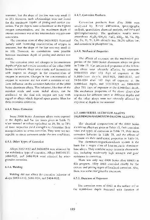
seawater, but the slope of the line was very small (1
to 25). However, such relationships were not found
for the maximum depths of pitting and crevice cor-
rosion. The pit depths were a maximum at the highest
oxygen concentration, and the maximum depth of
crevice corrosion was at the intermediate oxygen con-
centration.
The corrosion rates of alloy 5456-H321 decreased
linearly with increasing concentration of oxygen in
seawater, but the slope of the line was very small (1
to 10). However, no correlations were possible
between maximum depth of pitting and crevice cor-
rosion.
The corrosion rates and changes in the maximumdepths of pits and crevice corrosion of the other 5000
Series aluminum alloys were erratic and inconsistent
with respect to changes in the concentration of
oxygen in seawater. Changes in the concentration of
oxygen in seawater did not exert a constant or uni-
form influence on the corrosion behavior of the 5000
Series aluminum alloys. This behavior, like that of the
stainless steels and some nickel alloys, can be
attributed to the dual role oxygen can play with
regard to alloys which depend upon passive films for
their corrosion resistance.
6.4.7. Corrosion Products
Corrosion products from alloy 5086 were
analyzed by X-ray diffraction, spectrographic
analysis, quantitative chemical analysis, and infra-red
spectrophotometry. The qualitative results were:
amorphous A1 2 3-XH 2 0, NaCl, Si0
2 , Al, Na, Mg,
Cu, Fe, Si, Ti, 5.8% chloride ion, 26.2% sulfate ion,
and considerable phosphate ion.
6.4.8. Mechanical Properties
The effects of exposure on the mechanical pro-
perties of the 5000 Series aluminum alloys are given
in Table 72. The mechanical properties of the follow-
ing alloys were adversely affected by exposure:
5456-H321 after 123 days of exposure at the
6,000-foot depth; 5052-H32, 5083-H113, and
5456-H34 after 403 days of exposure at the
6,000-foot depth; and 5456-H321 and 5456-H34
after 751 days of exposure at the 6,000-foot depth.
The mechanical properties of the above alloys after
exposures for different times at different depths and
of the other alloys were not adversely affected by
exposure at depth in the seawater.
6.4.4. Stress Corrosion
Some 5000 Series aluminum alloys were exposed
at the depths and for the times given in Table 71
when stressed at values equivalent to 30, 50, or 75%of their respective yield strengths to determine their
susceptibilities to stress corrosion. They were not sus-
ceptible to stress corrosion under the test conditions.
6.4.5. Other Types of Corrosion
Alloys 5052-H32 and 5456-H34 were attacked by
the exfoliation type of corrosion. Alloys 5083-H113,
5086-H32, and 5086-H34 were attacked by inter-
granular corrosion.
6.4.6. Welding
Welding did not affect the corrosion behavior of
alloys 5083-H113, 5086-H34, and 5454-H32.
6.5. 6000 SERIES ALUMINUM ALLOYS(ALUMINUM-MAGNESIUM-SILICON ALLOYS)
The chemical compositions of the 6000 Series
aluminum alloys are given in Table 73, their corrosion
rates and types of corrosion in Table 74, their stress
corrosion behavior in Table 75, and the effects of
exposure on their mechanical properties in Table 76.
The aluminum-magnesium-silicon system is the
basis for a major class of heat-treatable aluminum-
base alloys. They combine many desirable characteris-
tics, including moderately high strength and good
resistance to corrosion.
There was only one 6000 Series alloy (6061) in
this program. Alloy 6061 corroded chiefly by the
crevice and pitting types of localized corrosion. Also,
there was some intergranular corrosion.
6.5.1. Duration of Exposure
The corrosion rates of 6061 at the surface and at
the 6,000-foot depth decreased with duration of
189

exposure, but not uniformly, while those at the
2,500-foot depth increased with duration of expo-
sure. However, the maximum depths of pitting and
crevice corrosion increased with increasing duration
of exposure at the surface and at depths of 2,500 and
6,000 feet.
6.5.2. Effect of Depth
Although the corrosion rates and the maximum
depths of pitting and crevice corrosion were greater at
depth than at the surface, these increases did not
increase uniformly with increasing depth. Depth
exerted no uniform influence on the corrosion
behavior of alloy 6061.
6.5.3. Effect of Concentration of Oxygen
The corrosion rates and maximum depths of
pitting and crevice corrosion decreased with
increasing concentration of oxygen in seawater. The
maximum depths of crevice corrosion decreased
linearly with increasing oxygen concentration. The
corrosion rates and maximum depths of pitting
decreased constantly, but not uniformly, with depth.
6.5.4. Stress Corrosion
Alloy 6061-T6 was exposed at the depths and for
the times given in Table 75 when stressed at values
equivalent to 30 and 75% of its yield strength to
determine its susceptibility to stress corrosion. Alloy
6061-T6 was not susceptible to stress corrosion under
the test conditions.
6.5.5. Welding
The corrosion of alloy 6061-T6 was adversely
affected by welding. Alloy 6061 was attacked by
intergranular corrosion in the "as-welded" condition.
6.5.6. Mechanical Properties
The effects of exposure on the mechanical pro-
perties of alloy 6061-T6 are given in Table 76. The
mechanical properties of 6061-T6 were adversely
affected by exposure in seawater. Those specimens
which had been welded and which had been attacked
by intergranular corrosion were the most seriously
affected.
6.6. 7000 SERIES ALUMINUM ALLOYS(ALUMINUM-ZINC-MAGNESIUM ALLOYS)
The chemical compositions of the 7000 Series
aluminum alloys are given in Table 77, their corrosion
rates and types of corrosion in Table 78, their stress
corrosion behavior in Table 79, and the effect of
exposure on their mechanical properties in Table 80.
Combinations of zinc and magnesium in
aluminum provide a class of heat-treatable alloys,
some of which develop the highest strengths presently
known for commercial aluminum-base alloys. The
addition of copper to the aluminum-zinc-magnesium
system, together with small but important amounts
of chromium and manganese, results in the highest
strength, heat-treatable, aluminum-base alloys
commercially available.
The 7000 Series alloys were attacked by crevice,
edge, exfoliation, intergranular, and pitting types of
corrosion. Corrosion of the Alclad alloys was by
shallow pitting and crevice corrosion, slight blistering,
and general corrosion.
Because of the erratic behavior of the 7000 Series
aluminum alloys during exposure in seawater at
depth, it was impossible to find any correlation
between their corrosion behavior and duration of
exposure, effect of depth, or the effect of changes in
the concentration of oxygen in seawater.
A practical case of unusual corrosion on an
aluminum alloy was encountered with the Alclad
7178-T6 aluminum alloy buoys used in the installa-
tion of the STU structures. During the retrieval of
STU 1-3 after 123 days of exposure, the buoy, which
was 300 feet below the surface, was found to be
corroded. White corrosion products on the bottom
hemisphere covered areas where the cladding alloy
had corroded through to the core material. The top
hemisphere was blistered, the blisters being as large as
2 inches in diameter and 0.75 inch high with a hole in
the top of each blister. The hole in the top of the
blister indicates the origin of the failure: originally a
pinhole in the cladding alloy existed where seawater
gained access to the interface between the cladding
alloy and the core alloy. When this blister was
sectioned to inspect the corrosion underneath, it was
found to be filled with white crystalline aluminum
oxide corrosion products. It appeared that seawater
penetrated the cladding alloy at a defect, or a pit was
initiated at a particle of a cathodic metal (probably
190

iron), and the corrosion was then concentrated at the
interface between the two alloys (cladding alloy and
core alloy). The thickness of the remaining Alclad
layer indicated that it had not been sacrificed to
protect the core alloy as was its intended function.
On the other hand, the selective corrosion of the
Alclad layer on the bottom hemisphere and the
uncorroded core material showed that, in this case,
the cladding alloy was being sacrificed to protect the
core material as intended.
When an attempt was made to repair these buoys
for reuse by grinding off all traces of corrosion prior
to painting, it was found that the corrosion had pene-
trated along the interface between the cladding alloy
and the core alloy for considerable distances from the
edges of the blisters and the edges of the holes where
the cladding alloy layer had been sacrificed. Polished
transverse sections taken from the buoy through
these corroded areas corroborated the indications
found from grinding operations. Metallurgical
examinations showed that the corroded paths were,
in fact, entirely in the cladding alloy, with a thin
diffusion layer of material between the corrosion
path and the core material.
Blistering of Alclad aluminum alloys such as
encountered with these Alclad 7178-T6 spheres was
very unusual. Blistering due to corrosion and the
rapid rate of sacrifice of Alclad layers had not been
encountered previously by the author and other
investigators in surface seawater applications. Because
of this unique blistering one of the spheres was sent
to the Research Laboratories of the Aluminum Com-
pany of America where an investigation was made to
determine the mechanism of this behavior.
Wei [15] showed that there was preferential
diffusion of zinc over copper from the core alloy into
this interfacial zone. The high zinc and low copper
contents of this interfacial zone rendered it anodic to
both the cladding and core alloys. Selective attack
was inevitable once corrosion reached this anodic
diffusion zone.
That this type of blistering has been encountered
on buoys at depths from 300 to 6,800 feet
emphasizes the fact that there is some factor present
which either is more influential at depth or is not
present at the surface. The fact that this thin anodic
zone is probably present in all Alclad 7178-T6 pro-
ducts and, as such, is not blistered during surface
seawater exposures indicates that the seawater
environments at depths of 300 feet and greater differ
from the seawater environments at the surface, at
least with respect to the corrosion behavior of this
alloy.
6.6.1. Stress Corrosion
The 7000 Series aluminum alloys were exposed at
the depths and for the times given in Table 79 when
stressed at values equivalent to 30, 50, and 75% of
their respective yield strengths to determine their sus-
ceptibilities to stress corrosion. Alloys 7075-T6,
7079-T6, Alclad 7079-T6, and 7178-T6, failed by
stress corrosion cracking.
6.6.2. Corrosion Products
Corrosion products from alloy 7079-T6 were
analyzed by X-ray diffraction, spectographic analysis,
quantitative chemical analysis, and infra-red spectro-
photometry. The qualitative results were: amor-
phorous A1 2 3"XH
2 0, NaCl, Al metal, Al, Cu, Mg,
Mn, Zn, Na, Ca, traces of Ti and Ni, 2.82% chloride
ion, 16.7% sulfate ion, and considerable phosphate
ion.
6.6.3. Mechanical Properties
The effects of exposure on the mechanical pro-
perties of the 7000 Series aluminum alloys are given
in Table 80. The mechanical properties of alloys
7002-T6, 7039-T6, 7075-T6, 7075-T64, 7075-T73,
7079-T6, and 7178-T6 were adversely affected.
191

Table 57. Chemical Composition of 1000 Series Aluminum Alloys, Percent by Weight
AlloyGage
(in.)Si Fe Cu Mn Zn Al
fl
1100 - - — - — - 99.0
1100-0 - b b 0.14 0.03 - R1100-H14 0.050 0.14 0.55 0.14 - 0.06 R1180 0.050 0.06 0.08 0.002 0.002 - R
flR = remainder.
fc Si+ Fe = 0.57
Table 58. Corrosion Rates and Types of Corrosion of 1000 Series Aluminum Alloys
Alloy EnvironmentExposure
(day)
Depth
(ft)
C orrosion
SourceRate
(mpy)
MaximumPit Depth
(mils)
Crevice
Depth*
(mils)
_, bType
1100-H14 W 123 5,640 2.0 39 P INCO(3)1100-H14 S 123 5,640 3.1 41 P INCO(3)1100-H14 W 403 6,780 4.2 62 C(PR) INCO(3)110OH14 S 403 6,780 1.3 62 62 C (PR);P (PR) INCO (3)
1100-H14 W 751 5,640 4.5 62 C(PR) INCO(3)1100-H14 S 751 5,640 2.0 62 C(PR) INCO (3)
110OH14 W 1,064 5,300 3.0 62 C(PR) INCO (3)
1100-H14 W 1,064 5,300 1.8 S-P S-C S-C ; S-P CEL (4)
1100-H14 S 1,064 5,300 1.0 62 C(PR) INCO (3)
1100-H14 W 197 2,340 5.6 62 C(PR) INCO (3)
1100-H14 w 197 2,340 <0.1 23 E;P REY(14)1100-H14 s 197 2,340 <0.1 I 1 I-C;I-P INCO (3)
1100-H14 w 402 2,340 1.6 62 C(PR) INCO (3)
1100-H14 w 402 2,370 0.9 I 50 C(PR);I-P CEL (4)
1100-H14 s 402 2,370 0.5 26 26 C;P INCO (3)
1100-H14 s 402 2,370 0.5 I 50 C (PR); IP CEL (4)
1100-H14 w 181 5 1.4 S S-C INCO (3)
1100-H14 w 366 5 0.6 13 13 C;P INCO (3)
1180-H14 w 402 2,370 1.0 1 50 C(PR);I-P CEL (4)
1180 w 402 2,370 <0.1 41 E;S-P REY(14)1180-H14 s 402 2,370 0.8 I 50 C (PR); IP CEL (4)
W = Totally exposed in seawater on sides of structure; S = Exposed in base of structure so that the lower portions of
the specimen were embedded in the bottom sediments.
Symbols for types of corrosion:
C = Crevice P = Pitting
E = Edge PR = Perforated
I = Incipient S = Severe
"Numbers refer to references at end of report.
192
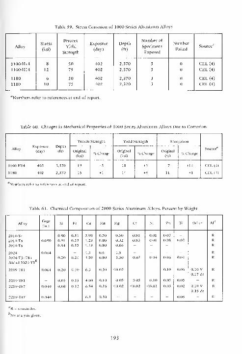
Table 59. Stress Corrosion of 1000 Series Aluminum Alloys
AlloyStress
(ksi)
Percent
Yield
Strength
Exposure
(day)
Depth
(ft)
Number of
Specimens
Exposed
Number
FailedSource'
7
1100-H14
1100-H14
1180
1180
8
12
6
10
50
75
50
75
402
402
402
402
2,370
2,370
2,370
2,370
3
3
3
3
CEL (4)
CEL (4)
CEL (4)
CEL (4)
"Numbers refer to references at end of report.
Table 60. Changes in Mechanical Properties of 1000 Series Aluminum Alloys Due to Corrosion
Exposure DepthAlloy ;. , ,/.' (day) (ft)
Tensile Strength Yield Strength Elongation
SourceOriginal
(ksi)% Change
Original
(ksi)% Change
Original
(%)% Change
1100-H14 402 2,370
1180 402 2,370
19
15
-2
+ 1
18
14
+ 3
+4
7
11
+ 14
+ 1
CEL (4)
CEL (4)
Numbers refer to references at end of report.
Table 61. Chemical Composition of 2000 Series Aluminum Alloys, Percent by Weight
AlloyGage
(in.)Si Fe Cu Mn Mg Cr Ni Zn Ti Other Al°
2014-Te _ 0.80 0.34 3.90 0.70 0.50 0.01 0.01 0.03 - - R
2014-T6 0.050 0.91 0.53 4.23 0.80 0.32 0.03 0.01 0.08 0.02 - R
2014-T6 - 0.84 0.35 4.43 0.80 0.66 - - - - - R
2024 0.064 - - 4.3 0.6 1.5 - - - - R
2024-T3+T81 - 0.20 0.20 4.50 0.80 1.50 0.02 0.04 0.06 0.01 R
Alclad 2024-T3*
2219-T81 0.064 0.20 0.30 6.3 0.30 <0.02 - - 0.10 0.06 0.10 V0.17 Zr
R
2219-T81 - 0.05 0.15 4.00 0.10 0.05 0.05 0.10 0.05 0.05 - R
2219-T87 0.040 0.08 0.12 6.54 0.26 <0.02 <0.02 <0.02 0.03 0.02 0.10 V0.15 Zr
R
2219-T87 0.040 - - 6.3 0.30 " " - 0.06 - R
R = remainder.
No analysis given.
193
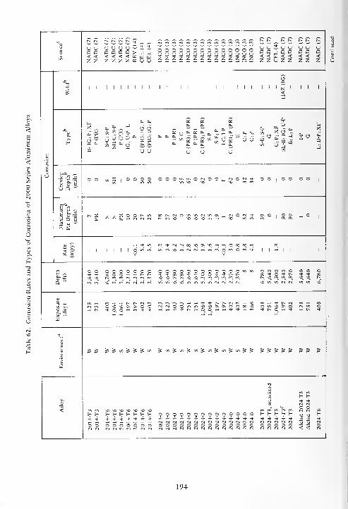
r~ r^ r^ r> t-~ t^. [-^
3O
Q Q< <z z
NADC
(
NADC
(
NADC( NADC
(C •? •?
> j jw u was u u
U Ua a< <z z
Jpau
UQ<Z
u
<z
a<z
Q<Z
uD<Z
OOOOOOOOOOOOOOUUnJOUUnJUnJUnJUnJUzzzzzzzzzzzzzz
-O5
"u 1 1 1 1 1 1 ! 1 1 I 1 1 1 1 1 1 1 1 1 1 1 1 1 1 1 1 N 1 1 1 1
S <X
a,a. a. £ £ 2
a. ^ ^ .. 6"
P pP
(PR)S-C (PR);P(P
P
(PR)(PR);P(P S-P S-E;P
I-C;
I-P
(PR);P
(P
E C;P C;P
a. Oh
Xa6"
Da. X
.. EL
9, r
<s>
rJ
i d a.
p(PR);
I
(PR):
I- Owen
si
J" a, O a."
aJ'
CO V u u u u C/l
'£
o
oU W-& ^
He o o »8i-° 000 OOOminotNOO_fNiO!N^-1in in in no no no "i rn
U Q w
eic3 *j •-.
E & = t- c£ Oi O O t- m ooc^rNJOmmrNiinONrNlorS^- On O . c On .
x Q E a. Cu ^ <n cs c*i N n io no no no u-i *—1 no mm m m m
sT
\ !1 1 1 1
rt * m WtMNCOiOffi^HHOOSOCH1 1
On
1 1 1 1 1O m tn mmNO^-i(NrN] -H-Hr^O'nOmTj-as j= V V
O O O O 000 OOOOOOOOOOOOmin O O - C O-3- + X o o ^t- -^- r-- t^ •+-tcc»-t-<)-OOTt--+t^l^ CO if O * C^ -f Tj- 00
Q ""•O NO f~ m m m NONOr^r^NONOrnmrnmmm t~- NO
no in « <N „NO NO
NOin in * in in n <N <M IN mu^NONOminu-ju-irsl(NfN)(N
1! m * -4- r^ C-* rvl M mmmwN^H^HrtTl-r^r^rNiN^HNO * t^w >* O n0 NO On On O O (NrJOOt^imNONOONONOOOONO O in NO C\ cG « .-H t^ "3- o_ o_ >-i .-1 + ^J- HrH + 'tlVNOOrHrH't^rtrn 3- t^ O -t- t^ *C T3
r-T rt" i-T
W
Eco
3= S 55«^ iS & CO St/I-St/Ijscn^e/I^i/N^^^^ £ S £ »s 5s & S £
'>
cm
T3
73O H HC 4- 4
CnI NO O
< NO NO O NO NO NO NO NO
h H H H f;" (7 h- H H 09090000000909 H H H H H -O -a h-
4- 4- 4-4-4-4- 4-4-4- 4-4-**4-4-4-4-4-4-4-4-4-4- 4- 4- 4- 4- 4- 4-NNNNMMtNiNNNNtNlrNtN CNl CNl
o o 0000 000 OOOOOOOOOOOOOO : O< <(N (N CN (NNlNlMrMNMNMlNiNNNN (N (N (N 01
194
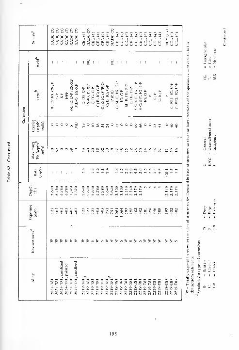
3o00 sjZUsJCJsjZsJ(J<JsJ<JCJCJCJCJsJ
REY
(14)
CEL
(4)
CEL
(4)
NADC
(7
NADC
(7
NADC
(7
NADC
(7
CJ CJQ Q< <Z Z
co
o
ou
-aT3
1 1 1 1 1 1 2 1 1 1 1
'^1 1 1 1 1 1 1 1 1 1
III
a.
a.
az
U6" * & &- en X zXw«
X* XW V4- w
°wW Qason
~ 0. a ab >•?» O =7 Cfi 00
ft/ X ft-ri CI rn - CJ <V •- -
O i" U - a. - P- u "V " O U U & a.
- ^ - 15 [5 ^ " U O CJ ft- '-
._ -r .. tiJ "1 w ft- -j « w T. oo c/) sCJ X CJ .- u .- en A til .- .-
a o o - 5i WW
ft- ft*
6 66" 6"
ft- T. T_
£ £
CJ u
1 8-1CJ Q ~
o o o o -1 inOOoOTj-rj-Or-OOOONOOOrj^ o o o
E g-5'3 Q E
5 ji;
O IN o o ON O 'OOOui(NOQir^ooir»(NcoO'vl-OcorN) <N O VC
rt o-
5 E1 1 1 1 1 1
O t> ^O h i- vOinvOOWiOirsu-i-rj-rr rt r- rn
„ ,.™ ,„_.__ O -H rt
V
°- 3o o o o+ CO CO 00so t^ r* r*
o o OOOOOOOOOOOOOminu^u-,-^^-Tf00C0-^--^-OO-^-Tj-r^c^sOsOsOt^r^sOsO'^f^i'^r^irnro
o o o-*• r~ r--
tr» so so so (N <N iriu->iAsosommmm<Nlfsl(Nrsl
1?o- -a
w
tM O O O-1 * T)- >)-
a o 123 123 123 403 403 751 751
1,064 1,064
197 197 402 402 181 398 540 588
N N MON o ort Tt" *
c
£B
Cw
=s S S 5 S 5 &jSooi5cnjS5i5coi5c/5-5aoi5&^-5 S S oo
o
<
T3
o .EC «rt O-
73
73
Q 73t^ t^ t^XXXH H H
X X X Xh- H h- H4 4 4 4o o o o
CO COH H4 4o o
xxxxxxxxxxxxxxxxxr-c-Hc-r-c-r-r-r-r-r-f-f-E-S-i-H
SSSSPISSSSSSSSSSSS fS (N fS
w Co
^E
•£ j S
u ^ 'a.
« 5 CJ CJ
O II II II
195
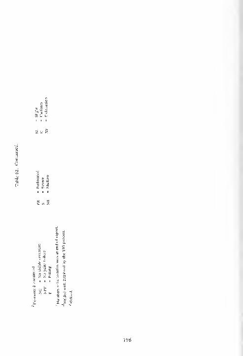
e 'a
» m
a1i
% S
> "cS
J3Cl, en
n
C/5
II
g =0- C/3 t/5
E 2
196
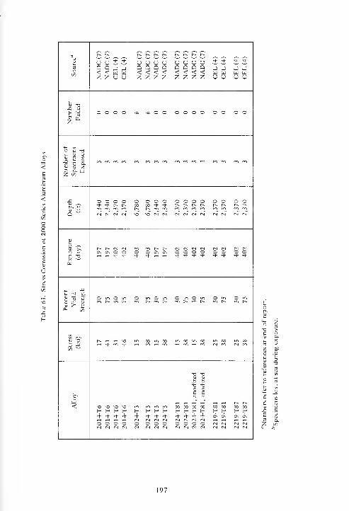
Q r^ r-~ r^ r^ r^ i-^ r~ r~ l-^ f~<D
u u S S u u u u u U u u * ^ 't *•
3 Q Q j _i Q Q Q Q Q Q Q Q J j J JCO <! < w w < < < < < < < < w w U W
z z u u z z z z Z Z Z Z u u O U
<u -o_Q u
1 ^3 tLZ
o o o o -a -a O O o o o o o o o o
O C T3j_ (U 0>MS ^ ^ ^ p^ m m m m m m <r> m m m m mP u 9-C <u X3 D. W2 co
jC o o o o o o o o O O O © o O o oa. 3 tJ- ** f~ r- CO 00 -tf- Tt" f~ t-~ p~ t^ r^ r^ r- t-^
t-~ r-- m m en mQ ""
cm cm cm cm •O VO N N CM cm cm CM cm CM CM CM
u3 ^"^ES >, N h N N m ro r— t> CM cm CM CM CMO 5s ON ON O O O O C\ On o o o o o o o oQ. T3 ^H rt Tj- Tf -* ,J- rH rH Tt- -t- "d- * * -1- * *X —
'
H
(J J=c "° boH U c O in O m O in O in o o o O in
ti vr ^ m r^ in r^ m [n <^i hs t^ f~ r^ in r^
1^ rt H VO in M « oo oo oo oo m oo£ * H * m rj- m cm CM en
co "-'
T3 -d4JN NT3 uO oC crt
o^ ,_, ,_, ,_7 T-T T_( rH r^ r-~
< \o o \o o 00 oo oo 00 oo 00 00 00
^ ^ fr ^ H- h- h- h- H H H H H H H H4 4 4 4 4 4 4 4 4 4 4 4 on ON ON ON
CM CM CM CM CM CM CMO O O O o o o o O o o CMCM CM CM <N CM CM CM CM CM cm cm cm CM CM CM
197
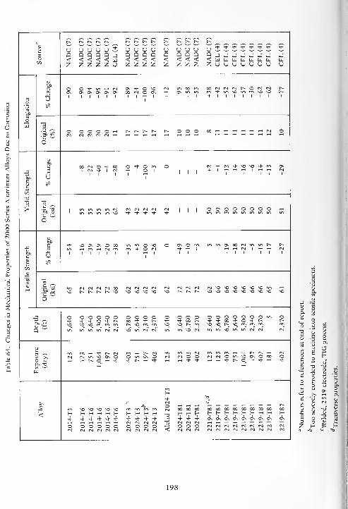
a, ,3
_^^
U U U U * U U u U U u U O -+ -1- •* Tt- * -t •+ ?3 G a a Q a J Q Q Q Q Q a a Q o J J J J J J _J JO < < < < < w < < < < < < < < < W UJ w u w til W til
Z z z Z z o z Z Z z Z z z Z z u U u o u U u U
V60c o o •* CM ON + o vo CM oo 00 CM t^ o CM CM r~rt 0\ ON o o ON ON oo CM o ON ON in * VO O VO r^-C
I | I 1 I i + 1 1 i + I 1 1 1 1 1 1 i
c Uo ^60COw rt
s -^ o o o o o ,_, t-- t~ f» r-^ t^ o o o 00 CM o6p ^ CM CM cm CM CM
o
60c ao CM c t|- oo © ^- c O CM CM •1- VO vo "* Ov
_C -C 1
+ CM1
-1-
1
1 CM1 1
1 c i
1 1 1
+ I
1 1 1 1 1
CM1
SO Uc
=S
to
T3OJ
s ^> l CM CM CM CM CM CM1 1 1
o O O o o o o O!a° .3 vo ^ •* Th tl- "*
o
u60c <* VO ON ox o oc o vO O ON o rri OS CO CM in t^ r^
60 J31 1 1 Y
CM1 1 l
+ o CM1
-1-
1 1
i + 1
1 1 -
CM 1
1 1 1
(VI
1
c U 1
ajo?
V
c
H in CM CM CM CM oo CM CM CM CM CM CM CM CM CM O VO VO VO vo VO in
i1
^- VO f^ t^ t~ r~ vo VO VO VO VO \o f~ f~ t^ VO \o VO VO VO vo VO VO VO
6""
j O O 3 o o o O O o O o o o O O o o o o o o O** -t <+ o -1- t> X ^h + f~ ^t -+ CO r- 1- + 00 "* O tJ- c^ t-VO vo vo m f~ *Q rr> fn o o t~- m O VO l-^ VO m m m 1*1
C5
"in in In IT. CM CM vo m CM CM u-> ir> VO CM in in VO m m cm CM cm"
•
1 >>* t^ CM t^ CM CM m <* t- CM (N
IN CM vo ON 3 o ON O CM CM O o CM CM O u-> VO ON O CO O3 rt I> ©_ -* * f~ -+ -1- -1- -t- t> O rH •* 'J-
X T3< '-'
uJ
H4 Q
_or
-0CMo ,_, ^ ,_, ^ ,_< rt rt -H ^H ^ ,_, t^
m vo vo vo o VO m rrt CM 00 oo CO 00 00 CO CO 00 00 CO oo oo
< t? H 'r- H '- H H H H H -a H H H H H H H H Et- H H H4 4 4 4 4 4 4 4 4 4 4 4 4 ON oV Ov ON on Ov ON Ov Ov
CM CM CM CM CM <n CMo o c c s o o o O O < o o O CM CM CM ^J (N CM CM CM (MCM CM CM CM CM CM CM CM CM CM CM CM CM CM CM CM CM CM CM CM CM CM
6 S
Z H ^ H
198

< o: d 05 05 05 05 05 05 05 »5
H 1 1 qd 1 1 1 1 1 1 q
©
o C-. 00 o fN
, 9 o *-H~ o o T-1 o o
N 1 o o o oVo o © o
o o oZ o o
V1 1 1 ©
1_ o c ©u o o
Vo
c-l~ m
o o o os o o
Vo © ©
c « o „ .n o o o ors) (N "-
1 r-) o m "-1 CN *-f tH
1—1 *"* T—l © *"*
3u
o m O M3 rs ©1
"""! o CM T-l t-H ^H <N *—i oo o o o o o © o o
« o o oo o 00 © ©U, 1
* (N f~ U"i in "* r- No o o o O o o o
in o o o m o v> ©1
*"! »H \0 (S *-i ^H oo o o ~ o o © o
<u ^ rri
BO CN V)1 1 1
*—
1
o = 1 1
o o o ©
Th cs *X s bo
c Xo* rr> T! ro
<N Tj- -t * * ©o
— O
< I X X s Xm u
mo o o o n n ©o o o 3 3 o © 3 <
199
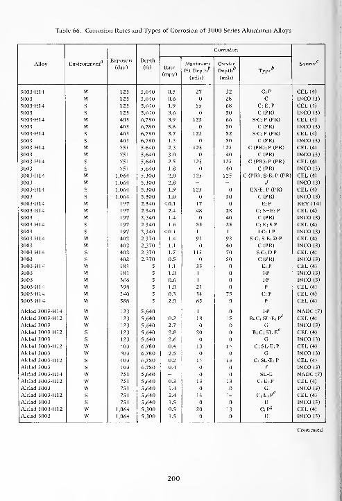
Table 66. Corrosion Rates and Types of Corrosion of 3000 Series Aluminum Alloys
Alloy EnvironmentExposure
(day)
Depth
(ft)
Corrosion
SourceRate
(mpy)
MaximumPit Depth
6
(mils)
Crevice
Depth6
(mils)
Type6
3003-H14 W 123 5,640 0.5 27 32 C;P CEL (4)
3003 W 123 5,640 0.6 28 C INCO (3)
3003-H14 S 123 5,640 1.9 55 68 C; E;P CEL (4)
3003 S 123 5,640 3.6 50 C(PR) INCO (3)
3003-H14 W 403 6,780 3.9 125 66 S-C;P (PR) CEL (4)
3003 W 403 6,780 3.8 50 C (PR) INCO (3)
3003-H14 S 403 6,780 3.7 125 52 S-C;P (PR) CEL (4)
3003 S 403 6,780 1.3 50 C(PR) INCO (3)
3003-H14 W 751 5,640 2.3 125 125 C (PR);P (PR) CEL (4)
3003 W 751 5,640 3.0 40 C (PR) INCO (3)
3003-H14 S 751 5,640 2.5 125 125 C (PR);P(PR) CEL (4)
3003 S 751 5,640 1.8 40 C(PR) INCO (3)
3003-H14 W 1,064 5,300 2.0 125 125 C (PR); S-E;P (PR) CEL (4)
3003 W 1,064 5,300 2.8 - - d INCO (3)
3003-H14 S 1,064 5,300 1.9 125 EX-E;P(PR) CEL (4)
3003 S 1,064 5,300 1.0 50 C(PR) INCO (3)
3003-H14 W 197 2,340 <0.1 17 E;P REY (14)
3003-H14 w 197 2,340 2.4 48 28 C;S-E;P CEL (4)
3003 w 197 2,340 1.4 40 C(PR) INCO (3)
3003-H14 s 197 2,340 1.6 55 25 C; E; S-P CEL (4)
3003 s 197 2,340 <0.1 I I I-C; IP INCO (3)
3003-H14 w 402 2,370 1.4 91 93 S-C; S-E;D-P CEL (4)
3003 w 402 2,370 1.1 40 C(PR) INCO (3)
3003-H14 s 402 2,370 1.7 115 70 S-C; DP CEL (4)
3003 s 402 2,370 0.5 50 C(PR) INCO (3)
3003-H14 w 181 5 1.1 33 E; P CEL (4)
3003 w 181 5 1.0 I IP INCO (3)
3003 w 366 5 0.6 I I-P INCO (3)
3003-H14 w 398 5 1.0 21 P CEL (4)
3003-H14 w 540 5 0.3 34 75 C;P CEL (4)
3003-H14 w 588 5 2.0 65 P CEL (4)
Alclad 3003-H14 w 123 5,640 -I I-P NADC (7)
Alclad 3003-H12 w 123 5,640 0.2 18 15 B;C;SL-E;PS CEL (4)
Alclad 3003 w 123 5,640 2.7 G INCO (3)
Alclad 3003-H12 s 123 5,640 2.8 20 B;C;SL-Ee CEL (4)
Alclad 3003 s 123 5,640 2.6 G INCO (3)
Alclad 3003-H12 w 403 6,780 0.4 13 14 C;SL-E; P CEL (4)
Alclad 3003 w 403 6,780 2.5 G INCO (3)
Alclad 3003-H12 s 403 6,780 0.2 14 13 C; SL-E;P CEL (4)
Alclad 3003 s 403 6,780 0.4 / INCO (3)
Alclad 3003-H14 w 751 5,640 - SL-G NADC (7)
Alclad 3003-H12 w 751 5,640 0.3 13 13 C;E; P CEL (4)
Alclad 3003 w 751 5,640 1.4 G INCO (3)
Alclad 3003-H12 s 751 5,640 2.4 14 14 C; E; P^ CEL (4)
Alclad 3003 s 751 5,640 1.5 U INCO (3)
Alclad 3003-H12 w 1,064 5,300 0.5 20 13 C;P£ CEL (4)
Alclad 3003 w 1,064 5,300 1.5 U INCO (3)
200
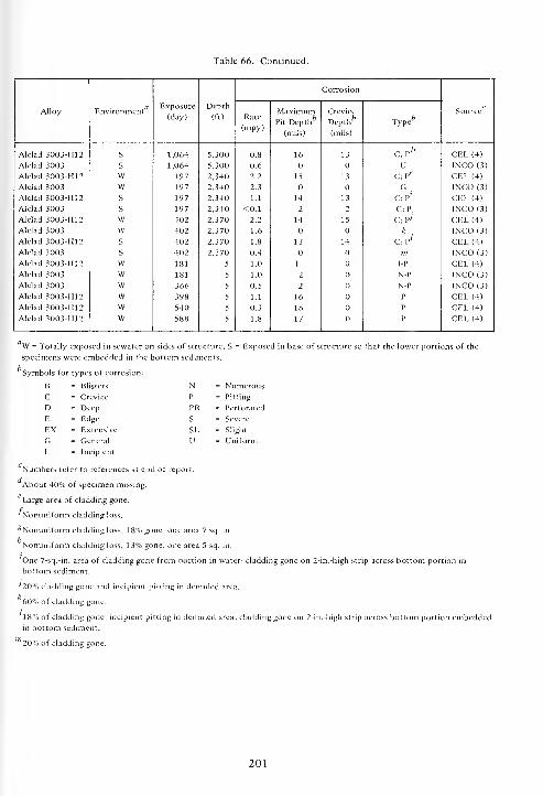
Table 66. Continued.
Alloy EnvironmentExposure
(day)
Depth
(ft)
Corrosion
SourceRate
(mpy)
MaximumPit Depth
(mils)
Crevice
Depth6
(mils)
Type
Alclad 3003-H12 S 1,064 5,300 0.8 16 13 c ;
p* CEL(4)Alclad 3003 S 1,064 5,300 0.6 U INCO (3)
Alclad 3003-H12 VV 197 2,340 2.2 15 13 C;P£ CEL (4)
Alclad 3003 W 197 2,340 2.3 G.
INCO (3)
Alclad 3003-H12 S 197 2,340 1.1 14 13 C; P' CEL (4)
Alclad 3003 S 197 2,340 <0.1 2 2 C;P. INCO (3)
Alclad 3003-H12 W 402 2,370 2.2 14 15 C;P; CEL (4)
Alclad 3003 W 402 2,370 1.6 k INCO (3)
Alclad 3003-H12 s 402 2,370 1.8 13 14 C; p' CEL (4)
Alclad 3003 s 402 2,370 0.4 m INCO (3)
Alclad 3003-H12 w 181 5 1.0 I (J IP CEL (4)
Alclad 3003 w 181 5 1.0 2 N-P INCO (3)
Alclad 3003 w 366 5 0.5 2 O N-P INCO (3)
Alclad 3003-H12 w 398 5 1.1 16 P CEL (4)
Alclad 3003-H12 w 540 5 0.3 16 P CEL (4)
Alclad 3003-H12 w 588 5 1.8 17 P CEL (4)
W = Totally exposed in sewater on sides of structure; S = Exposed in base of structure so that the lower portions of the
specimens were embedded in the bottom sediments.
Symbols fo types of corrosion:
B = Blisters N = Numerous
C = Crevice P = Pitting
D = Deep PR = Perforated
E = Edge S = Severe
EX = Extensive SL = Slight
GI
= General
Incipient
U = Uniform
Numbers refer to references at end of report.
About 40% of specimen missing.
Large area of cladding gone.
'Nonuniform cladding loss.
^Nonuniform cladding loss, 18% gone, one area 7 sq. in.
Nonuniform cladding loss, 1 3% gone, one area 5 sq. in.
One 7-sq.-in. area of cladding gone from portion in water; cladding gone on 2-in.-high strip across bottom portion in
bottom sediment.
•'20% cladding gone and incipient pitting in denuded area.
k60% of cladding gone.
18% of cladding gone, incipient pitting in denuded area; cladding gone on 2-in.4iigh strip across bottom portion embeddedin bottom sediment.
20% of cladding gone.
201

Table 67. Stress Corrosion of 3000 Series Aluminum Alloys
AlloyStress
(ksi)
Percent
Yield
Strength
Exposure
(day)
Depth
(ft)
Number of
Specimens
Exposed
Number
FailedSource"
3003-H14
3003-H14
6
9
50
75
402
402
2,370
2,370
3
3
CEL (4)
CEL (4)
"Numbers refer to references at end of report.
Table 68. Changes in Mechanical Properties of 3000 Series Aluminum Alloys Due to Corrosion
Tensile Strength Yield Strength Elon nation
AlloyExposure
(day)
Depth
(ft)Source
Original
(ksi)% Change
Original
(ksi)% Change
Original
(%)% Change
3003-H14 123 5,640 22 -4 20 -8 13 -43 CEL (4)
3003-H14 403 6,780 22 -48 20 -50 13 -77 CEL (4)
3003-H14 751 5,640 21 -20 21 -11 4 +25 NADC (7)
3003-H14 751 5,640 22 -24 20 -26 13 -72 CEL (4)
3003-H14 1,064 5,300 22 -3 20 -18 13 -20 CEL (4)
3003-H14 197 2,340 22 -6 20 -10 13 + 15 CEL (4)
3003-H14 402 2,370 22 +6 20 + 11 13 +5 CEL (4)
3003-H14 181 5 23 +4 21 -1 18 -1 CEL (4)
Alclad 3003-H12 123 5,640 19 -2 18 -1 14 -42 CEL (4)
Alclad 3003-H12 403 6,780 19 + 3 18 -1 14 CEL (4)
Alclad 3003-H12 751 5,640 19 -3 18 -4 14 -19 CEL (4)
Alclad 3003-H12 1,064 5,300 19 + 3 18 + 1 14 -12 CEL (4)
Alclad 3003-H12 197 2,340 19 + 1 18 +2 14 +7 CEL (4)
Alclad 3003-H12 402 2,370 19 + 1 18 14 -14 CEL (4)
Alclad 3003-H12 181 5 19 +4 18 + 1 14 +2 CEL (4)
Alclad 3003-H14 123 5,640 21 " " 4 + 100 NADC (7)
Numbers refer to references at end of report.
202

< OS aS as as as as as OS aS as as es aS as as as as as OS
in o o iri. in .
H 1 1°
1 1 1
rt. 1
CM1
CM1
-1 1 1
c *-i oo o O o o o O o
r^ in in in . CM in rt-
N I| |
c1
!^
I
CM O CMI
a1 1 1
»—
t
CM oo o O O o o o o o
CM oo
z 1 1 1 1 1 1 1 1 oV
1 1 1 1 1 o
In CM CM m CM CM r~ r^ « CM in incm cm <N CM O O o o O
u o o o O 1 d o o oV
o o o o o ° O ° o
0\ o - oo oS
^H m CM U~i en in in o f~ o o o o o o :_ f^ © o1-1 CM CM CM CM * •+ 1-1 CM in in m in in Ti- * m Tf •*
m T_1 in en in NO in r> t-~ in CM in oe .
iq c NO no O t^ CM t-~ t-~ X r^ en * en Tt- On
S 1 d oV
o o o O O o O o o O O © O O
NO+,^ CM in O o o oo o CM
u o 1 o o O i-H ^H1
*-H o tH »—
l
t-l © 1 1 O rH rH
o o o O o o o o o o o o O o O
* t-~ o o CM no c in o o& NO
1
'"H
-oen
1
"*1
u entj
1
"-I m1 1
CM m rt
o o O o O o O O O o
oo o ro o 00 o O in o o{?i
l-H1
1_l ^*I
*1
^ i—
1
<J1
— i—
t
I 1
*—
<
-1- r^
o o O o o o o = ° o
JB
CM
c o o o CM o m X n m.o no CM
- CMu o
d1 1 1 ©
d1 in
d1
dod d
1 1 1 1 c d d1
CJm
-*•no
^r «*•
I<* E X
^ cm" „ + +m r^ CM
-i- X cm Th + CM CM CM Tf- CM <*• <*•
< CM en
as o - X X I T1 X X X X X I r Xo CM CM cm CM en en "fr <*
CM
<NO \o no no no NO ^o no NO
00 oo no -/'. oo oo COo o o " o © o -1- «* Ti- -t- -+ ^ O -
r. o oCQ
203

t^ r^ t^ f^" S~8~~*~~u3O
REY(1 CEL(4 CEL(4
ooooooooooooooUUUCJUUUUUUUUUUzzzzzzzzzzzzzz NADC NADC NADC NADC-1 _
U u
Ow
•*>
o.a. o*
£
a. a- a- o- .. a & a. a .-u rt£r .-1
XF;PU-P L-P L;
F-D-
S-P
MO-C;
PP
SH-CRMO-C;SH-P S-C;SH-P P C;I-P C(PR);I-P
a, [i.>*H <J U
Xu w
c
8
ou «-oU -C -J O H rH min<M»Min<NinrginoOO>n o o o o °l°l c/)0 *° o o
"J! E
'O^O^O'O'O^O^O^O^O (S
U Q ~
E*c=> K -~E S--S * — — 0000u->0000__00_v>
1 m "J N * a,oiI^„ - oo mrg \o
s £
a >> t^OiAr-)rjrg^Hin00T-HTtf^(M\O * — — rs c*i .H ON
at o o o m<3-^-r-.c-)mm.-irfOOO — o o 1 1 6 1 d I I1 1 d d d d d
V V V V V V
j= o o o OOOOOOOOOOOOuim o o o o o oooooooo o os. sQ
r^ tv f. J-'t0000^t-T|-OO*^l-t^t^ o 00 <* Tt- !> *J-Tt-^-Tt-*-*f~f~ * *\0*0r*-t^^00<^^rr\mmm [-. m HI rfi ^CC^^C^O^"!'" -o oNNN inif)i0^^vl'n«N«NM m vO N M « inminmuirj<\l(\i m m
5 •r- (Nl fsj <N wfnmrftT-(^-tTt-^-l^r^(M(N^HvO * m t-~ t-^ eg mf*>*-i — *-ir*.c*l<NX >> O O O <MrNOO"imsO\OOvONOOOOvO VO o o\ o\ o (srJmir>u-iONOO fvl (NO jga. -a
"* "J" * — — -^-Tht^r^oO_— — *t--3-T-i ro o_ * i-H rH * — — r^t^r^. — ^^i- *H ^H
a
ac
Ec S5»i St«S«S'n5"3&C5&''>SS =s 5 & EO & S5S5"i?Sfi S C/5
>cU)
>.o Ts "a
< * * * (S (S fM (M M ******!** 3 SXII OOOOOOOOOOOOOO I XXII XXIIIXIX X X666 (NNNNNNNNNNNNNN M (N <N <N (N NNMNNNMN00 CO
o o o OOOOOOOOOOOOOO o o o o o OOOOOOOO o o
204
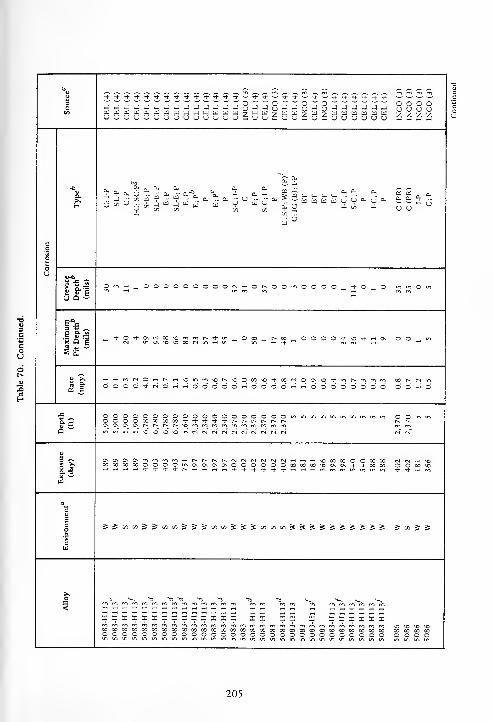
u^^^-^^-^-^Tj-Tj-^t-Tt-^-^^-^^^.^J-^Tj-^J-^'-^.^^.^.^.^J.^-^J-
3 j-ijjjjjjjjjjjjRjjP-i-iS-'S-j-J'-i-i-j-jUUUOOUUUUUUUUU — UU — UU — U — uuuuuu INCO INCO INCO INCOtf>
abo Si -la- _ c Cm Cl, cl
ft * a. 6 t M- a, - a.*, V - a, - SS^.u^. *
V C/l C/3 t/5 C/3 «,-i, en ...
C(PR) C(PR) IP C;P
c
8
u
Crev Dept(mil
Oo~H M ©000©00©OrM^HOr-^OOrnOOOO_(
-3-0 — O m in o in
Eic
5 *> .~ M -^-O^J-0\r>jcO\o^rnt^Tj-in OX t> X OOOOTt-^o^^CNr) mO\^o*ox<Nin-Hm —
in— h + M mm rt
S£ ~
^
(2 e
— —im<N©—<r^w*omm\nr^\OOX>0'3-XMOO\\nTi-mr'^mmm CO t, N If
oo©d^r^d^^oddoo^Hdod©'-i^-iodoo*dodd O © « ©
£ 0©0000©COOOOOO©©00©inminminininmmm©OOOMoOMcOTi-^Ti-Tt-4-r^r^r^t^r^r^Q ~ 0\C\0\0\r^f^t^l-~*ommmmmmmmmm
minmmvOvOvOvOin(N(N(N(NfM(SrNfS<NcN
3 C C-.o\0\0\mmmm*-ir^r^r^r^<NrNCNr^cv)<N>-<i-i'-H\OXXO©XXs |- XXXX©0©Oint3\CNO\0\©©©©©©XXX^OO\0\Tf'i-XX
•* * _, mX »-UJ
c
6co SSui»)iSf)fi55S«toSSS»)u)t«SSSSS5S5SS ?i»JJ>ca
>.
<« m"m m"*m
U "<3 13 13 13 13 ^ •*, ^ >*,
xxxxxxxxxxxxxx x x x x x xxxxxxxxxxxxxxxxxxxxxxxxxxxxxxxxxxx ^o >o « *o©00O00©00©©0©0©©0©©0©©©©0©0©© o o o o
205

^ ^^.^^'S-^^^^^ f^ P^-^-Tf^-^.^-Tj--!l-Tl-^- Ju J J J * J Ju * lJ-^--*-*Tj--tT)-Tj-'J-^-'* * •*•
3O JJ_1J><_1_1JJJ _i 9 -j -j -j -j -j J 2 J JJJJJJJJJJJ _) J00 HUlldlilUHIilUUliI a < w u sa w w b < B UUUUUUUUUIiJU U BUsJUUBUCJUUsJ U Z U U <J u u u z U UUUUUUUsJOUsJ u u
£a,
=3 Cl""a- * <v
-0
C;
SC-P
C;SC-P E;P B;P P C;I-P C;I-PIG(E);I-P P 1-CiP
ET NC-SDS-C;E;P
SL-P (PR);E;S
S-C;
IP
S-C;P
ft" N00 <»s
00
63
6"
00fc « (_ 0-
- a, £ B u * ^ ft. ^ b <n
» « « e^ «?. S 'a S v" vV O Jn
00 tjj
6" <"
O 1/5 £Oh
a.
00 OO ,i <"
c
3t
<J v-a
ill ms+OOOXXOO^ O 1 O O SO m X1 10 rsl in ^ SO
Os 000_xmx0___r"m — is-> ^- — — * csi r~
U Q ~
E*^3 £ ~E S--2'5 q 'e
m m N a, in O N O 1«s rr, m _ •* <N BJ m mt^-^HOsivsc^sOt^Ot^ rt Om rsl s+ <N rs> rsl f* t^TtmrsiiriT-i rsi ^ r-i rs>
5 .aw
1!^HM^^H^r}-u-lO-^-(N ^h Tt rsi r^ so x O Os MrtHNH^mNOSffliO y-H ^HOOOOOOO-iOO 6 1
h O O O rsi i O rtOOO^iOrt^-iOO^H O OV V V V
J3 OOOOOOOwinm OOOOOOO O O O OOOOOOOmininm O OO O O O * r^ r-* ^- 'i- s+ X X -* rr O O O O * s+ f~ rv O O
Q "" On OS rM IN rr> rn mm in * + N N M
SO SO so Os OS c^ r-* SO so Os rsi
in st"m in in in m SO so in in m mi * * N M M N
3 T 0\OsOOr^rslCs|T^XX <* s+OOI^t^rslfslTHX OX Os O£ >s
S.-3
XXsOSOOsOOXOsX rsl rsi rsl 00 X O O •c SO*OSOOsOsOOXOss+X X sortrtmmrt^-j-rtmin _| rt ,_, ,-H rH * * t^ r^ o_ OnmHHttHmininX -•'
II)
O^cvEc JinJ»lJ^(nJJJ S J 1/1 J i»5 in S 5 »s mSm^aiSi/lSSSS 00 j5
*>
cB
X_o a s"
-« -« •*: -« rsi rsi
< (SlM(s!N(N(NNNNrJ * * * + * + * * -* * ^-Th*'*-*^-^-^-'*^Tt-rt Ihxxxxxxxxxx X X X X X X X I I X IIIIIIIIIII X X
sososOsOsOsOsOsOsoso so so so so so so so so so SO SOsOsOsOsosOsOsOsOso so so soxxxxxxxxxx X X X X X X X X X X XXXXXXXXXX X X X0000000000 OOOOOOO O O OOOOOOOOOO
206

IJ
J- tt * * <* * * * * •* * * ^-+^-*<**>i-* * * * !" * * *3O
O O O OU y u uJ J J _i _i -J J _ _ _ _ _ -J-JJJJJJ-J > -i _i j J j j j
(/) td M z z z z www id cd _ _ _ _ _ uuuuoiaiEdU a u w id S ca w wCJ U uou u u u u u u u uuuuuuuu X u u U S U U (J
N
a.a.
t/3
u £ °- e-^ X- «!, Cd
U
I*
" £ *
w
N B-
< O£ S-J wa 6
B J °1 I *-- V) U
a, W->
i" J - J^- i t/3 CU c/5
^Q 6
X R
a. a. £ a. -5•j, * j,k a, °oa. . c . a. °- ' oa
6 <-> a, U ~ &* a." a.
V a."
on
a> 6" uSL-C;SL-ET C;P
C;
E;S-P
S-C;E;
I-P
C;
E;
F-P
c
8tou V4
l&l soeo o o oCsl CO
o o o o o o o o o o ^OsOmOOOO o " NJ in ro O <Sc/5 m in m
u a •=
£%3 " ^B 8- -a o _ o o __ o t-~ Os 00 * r» N in >t h ^ Os„Cs]__Cs100 — OS fs) O O O in Os _ >*
-j- m sO m ^ SO Csl * rt *""*"" rsl " rn tf *S E
^
I!^H ^ -)- so O m ^h n Os r-* m so os r*- m so so^sorrir^mwst^ w so t^ rf m h o »O iH
VO O -h o O rt O — o o o o o o oooooooo o
Vo o O ~ rsl -n O
V
j= O m O O m in O O O o o o o o o o OOOOOmmin o o o O O O O OO c^ t^ •* Tf 00 00 00 00 *•** * Tt- r^ t^ r^ t^ * r^ r^ t ^ i- oo 00
Q w*" 52 *0 ^ h r~ r^ t^ so ^ m ro so so so r^ t^
m m so SO so <5 m (SI N N rs» rs) (si rs« rsi <s csi rsl m in in so so
2 t; O rt M N rt VO rrs ^ t^ [^ 1^ r^rsir>]ps»fsioooco r^ (M rgso X o o oo so
•* + h m rj m o-. -( tt
o o O m OS Os Os OsOOOOOs^tco OS o o N N N O OT-l r-< 11 * *
u
<swc
6co vi S 5 v) S =J S U5 =J =S V) «S5Si« w^S^v)S^S S s^ yj S ^ on S («
cU
SOm*
>. -^ w
5"•3^3 >3 T3>! 13 13 "O ">3 "<3 "a T3 X
Tj" fs! N (SI N is)
X X XXX SB I X I I I I XXXXXXXX ^ S3 33 X X X X Xso so00 00
* + * * 4 4 4 4 4 4 4 4 4 4 44444444 XCsl
so so S S S S ino o •t + *• -t •t + + <* * •1- -t •+ * Th t't-t^t't-tt-f < •t •& * •* * -t *
207
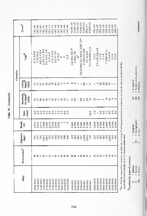
VJ t^ r^ [^ t^ f- t^
't*t^**-^-&-^-&*******r u u (J U u S (J***vt^*"t<|-
3O JJJJ-JJJJ-J-JJiJ Q Q Q Q Q J 2 JJJJJJJJuuuuuuuuuuuu < < < < < w < __„._____uuuuuuuuuuuu z z Z Z Z U Z UUvJvJUUUvJ
cX
OSvj
aua.
Ou °? °?
fe. X u u X u - w w a, a. •-
w w » o w r. w a- j u
0.
a as
en o
— ^
X
00
Uas
atxT
b><
Oh
£a.
a.
W
Q £w 5l
6" *I-C;P
E;CR(30);S-P
C;I-P C;IP C(PR);SL-E
C;E;
F-P
I-C;E I-C;E
w O"tn u £a.
a,
Uir>
eOS
'8 UtoU
U-imint^-^O^OOOTl-fMOOOO o o1
OS O oo x ^ in
1 |1 NN'tm^rfiH^w a. IN <N vo mu a -
eic3 s ^E —"5 5 'g
mr^O M-'Ol>-'^'-H '*(N vO -* - OS1
X IN m egjq t/3 ° £ ° °^Hin^mH^^fHrHTHrt m a. a. VO fH
* a.
a e
Or-i<NOu^^^Oi—irjr^'OOv1 1 1 1 1 I 6
V
O in (S rt -n * mrn 1 ddnddd(NMrM^i-'fMfM^T-Hr-HOO
w
X OOOOOOOOOmmu-i o o o o o o o ooooooooa. 3Q w
^-'t'tOO^^NN *1- 00 X * o o * +'*»00-+O')-^in >o
vO
« ««vovor^t^vomrrimininvovoinmrvirsi
3 — T_,^H^H Tj.^j.r^r-.<NtN^XO -J- * t- mprimm^H'tl^t^£ >> iniriui\0^0O0\O©00t>Tj- <s o 6 o vO ON cvicviOO*nvoo\0\8. -3 t^t^t^OO'-H'-'^-^-^Hroin rt TJ- -t P> o 9. " rtrt^->^-t^O_'-'-H
ua
acVEc ^^w^c/i^c/i^cn^^^ £ s y) £ 5 S C/i S55toS5S«'>
eId
Xo
% NNNNNNNNNMNN Tt- * -t * 1- * * *^-Tf-*-a--+^-^-xx^xxxxxxxxx I x X X X X X xxxxxxxxvOvovOvOvOvOvOvOvovovovo vO vo vO VO VO vo vo \O^O v©\0 , 1O vO vO*-*-t'^-^-^-^t--**->l-*TJ- * "t + Tt 't * * '+^^-rfrJ-Tt-Tj-Tt
.5 -a
•a i!
^ 6
- «
208

a -a
§1.2. 2 -o o
D 5 a
J= '~ 73
C/l
a>o
c a.,0C
J;>
C
n
Z £ — a. C/3a.
oE
oSoz a.
a. as— a. t/3
3E
i
s I sUJ u. I
Q u ui ui n I Z
Z S H
209

"vu
r-- t~» t~- r- r- i>
s s u u u u u u <d- "*• <*• •<* M" -* * >*** •* *3 w w c a q a a a W W W W J W W www J WOC/3
w w <<<<<:< w w WWW w w www w wu u 2 Z Z Z Z 2 u u u u u u u U U U u u
1> -T3
J3 IU
1 ^Z *
o o o o o o o o o o o o o o o o o o © o
o c -a^ e ".o .5 S m m m m m rn m m m rn rn rn rn rn rn CM rn m rn rn
c <u X3 a, pjZ t/3
.a o o o o o o o o O O o o o o o O © O O O
Q wr-~ t-- oo oo + «t t~- r~- r-- t- 00 00 00 r-- t-~ oo <* r^ r^ r^m m r-^ r-~ »^ *^> en en m m t-~ r- r^ m m t-~ m m m rn
CM CM ^O ^O N N N N CM CM \Q VO MD CM CM VO CM CM CM CM
OJ
3 "£ CM CM m m t~- r-- cm cm CM CM rn r^ CM CM CM m t^ CM CM CMO rt o o O O 0\ 0\ o o O O O 0\ © o o O OvO o oa. -a * * Tl- + H H * * •* * * rt + <* •* •>* rH * * *X ^-"
w
w -ec -a tcg u c O in O m O m O m O m in in in O in © in
%Z IT* qj in t^ m t~- rn r- m r^ in t-» r-- r- t-~ in r-~ r^ r^ r^ m r^
ft- w5
—i r- 00 .-< 00 t-h 00 rH in rM in rr. CM CM CM o o*3 -^ cm cm cm <-H CM r-H CM cm enC/5 "^
-o -o -o-& -ci -a
rt- **- cm cm cm cm cm cm * Tj- CM CM CM CM CM CM CMm m m mX X X X X X X X DC I X X X X X XII X X
< 6 6 CM CM CM CM CM CM CM CM rr> rr> rrt \o *o 4 + 4 \o VOoo oo oo oo oo in in in
o o o o o © o o O O o © oin in in
o o <t ^" *in in
210
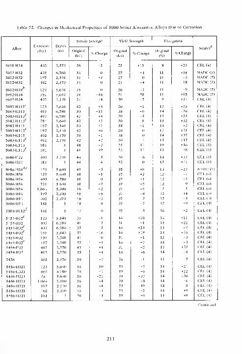
Table 72. Changes in Mechanical Properties of 5000 Series Aluminum Alloys Due to Corrosion
Tensile Strength Yield Strength Elon Ration
AlloyExposure
(day)
Depth
(ft)
aSource
Original
(ksi)% Change
Original
(ksi)% Change
Original
(%)% Change
5050-H34 402 2,370 28 +2 22 + 11 8 +25 CEL (4)
5052-H32 403 6,780 34 27 -4 11 -54 NADC (7)
5052-H32 197 2,340 34 -3 27 11 -3 NADC (7)
5052-H32 402 2,370 34 27 -4 11 -18 NADC (7)
5052-H346
123 5,640 35 26 + 3 11 +9 NADC (7)
5052-H34 751 5,640 34 -64 27 -58 11 +95 NADC (7)
5052-H34 402 2,370 37 + 4 30 + 7 9 + 34 CEL (4)
5083-H113c
123 5,640 42 . + 4 20 -1 13 +26 CEL (4)
5083-H113 403 6,780 50 -15 38 -6 14 -30 CEL (4)
5083-H113c
403 6,780 42 + 4 20 -5 13 +23 CEL (4)
5083-H113c
751 5,640 42 + 5 20 -8 13 + 32 CEL (4)
5083-H113 197 2,340 50 -1 38 -1 14 + 3 CEL (4)
5083-H113<:
197 2,340 42 +6 20 13 +21 CEL (4)
5083-H113 402 2,370 50 -1 38 14 + 37 CEL (4)
5083-H113'7
402 2,370 42 + 2 20 -1 13 + 17 CEL (4)
5083-H113 181 5 48 -2 35 -11 19 + 16 CEL (4)
5083-H113c
181 5 41 + 9 22 + 11 13 +8 CEL (4)
5086-H32 402 2,370 44 -5 30 -6 14 + 33 CEL (4)
5086-H32 181 5 46 -4 32 17 +41 CEL (4)
5086-H34d,(?
123 5,640 49 -3 35 + 8 13 -23 NADC (7)
5086H34 123 5,640 48 -1 37 + 2 12 -1 CEL (4)
5086-H34 403 6,780 48 37 -1 12 -5 CEL (4)
5086-H34 751 5,640 48 -7 37 -5 12 -9 CEL (4)
5086-H34 1,064 5,300 48 -2 37 -4 12 -3 CEL (4)
5086-H34 197 2,340 48 -5 37 -6 12 +4 CEL (4)
5086-H34 402 2,370 48 -3 37 -2 12 -3 CEL (4)
5086-H34 181 5 48 37 + 2 12 -9 CEL (4)
5086-H112^ 181 5 47 29 -3 16 -2 CEL (4)
5454-H32C
123 5,640 35 -1 16 + 10 14 -11 CEL (4)
5454-H32 403 6,780 41 -2 31 -1 13 -22 CEL (4)
5454-H32c
403 6,780 35 -2 16 + 23 14 -7 CEL (4)
5454-H32c
751 5,640 35 -16 16 +19 14 -36 CEL (4)
5454-H32 197 2,340 41 31 -1 13 -3 CEL (4)
5454-H32C
197 2,340 35 -3 16 -7 14 -3 CEL (4)
5454-H32 402 2,370 41 +4 31 + 2 13 + 27 CEL (4)
5454-1132 402 2,370 35 -4 16 +6 14 -6 CEL (4)
5456 402 2,370 50 -7 36 + 1 15 -7 CEL (4)
5456-H321 123 5,640 56 -10 39 -5 14 -24 CEL (4)
5456-H321 403 6,780 56 -1 39 -6 14 + 22 CEL (4)
5456-H321 751 5,640 56 -21 39 -33 14 -30 CEL (4)
5456-11321 1,064 5,300 56 -4 39 -8 14 -6 CEL (4)
5456-H321 197 2,340 56 -4 39 -10 14 CEL (4)
5456-11321 402 2,370 56 -1 39 -5 14 +9 CEL (4)
5456-11321 181 5 56 -1 39 -6 14 +9 CEL (4)
211

Table 72. Continued.
Tensile Strength Yield Strength Elon Ration
AlloyExposure
(day)
Depth
(ft)Source
Original
(ksi)% Change
Original
(ksi)% Change
Original
(%)% Change
5456-H34 123 5,640 61 -6 43 + 5 13 -34 NADC(7)5456-H34 403 6,780 58 -14 50 -21 3 -80 NADC(7)
5456-H34 751 5,640 58 -14 50 -44 3 -71 NADC (7)
5456-H34 1,064 5,300 58 -14 50 -14 3 +94 NADC (7)
5456-H34 197 2,340 58 -14 50 -8 3 + 170 NADC (7)
5454-H34g 403 6,780 58 -11 50 -14 3 + 196 NADC (7)
5456-H343 123 5,640 34 +10 - - 6 + 33 NADC (7)
5456-H343 123 5,640 58 46 + 2 9 +27 CEL (4)
5456-H343 403 6,780 58 -2 46 -6 9 + 54 CEL (4)
5456-H343 751 5,640 58 -2 40 -1 9 +27 CEL (4)
5456-H343 1,064 5,300 58 -1 40 -3 9 + 30 CEL (4)
5456-H343 197 2,340 58 -3 40 -1 9 +22 CEL (4)
' Numbers refer to references at end of report.
Transverse properties.
Transverse butt weld with 5052 rod.
Transverse butt weld, 5566 electrode, TIG process.
Mechanical properties transverse to direction of weld.
f' 3 in. x 3 in. x 1/2 in. angle.
*Anodized.
Table 73. Chemical Composition of 6000 Series Aluminum Alloys, Percent by Weight
AlloyGage
(in.)Si Fe Cu Mn Mg Cr Ni Zn Ti Al
fl
6061 — _ — 0.25 _ 1.0 0.28 _ _ _ R6061-T6 0.125 0.60 0.70 0.27 0.15 1.0 0.25 - 0.25 0.15 R6061-T6- - 0.6 - 0.25 - 1.0 0.25 - - - R6061-T6 — 0.50 0.30 0.20 0.05 0.95 0.15 - 0.06 0.04 R
R = remainder.
212

^
U3
^ J2 !2 C"i-
in jj — — — — y ^ ~ ua
in •
j j j j j 9 jo o o ou u o uz z z z
_J nua J J J
Jen PJ < < W uuuuww<au < W w UJ w w w w < w
u z Z S 00CQUUOUZUU z £ cc oa u u o u Z o
o"^-Cu ^6 as
Cu5
Cu Cu Cu,Qj Cu
^ --^ 6 "^ Cu Qi Cu uO 5Cu
02
U
CU NP(PR)
S-C;E;S- S-C;E;S-
E;S-P C;P IG;P IC;P
OS OS cu0- Cu Cu .-—
'~- U
u u
Cu
u
00
N<X
Cu
u / Z r'? U f3 r'l 6 r'l" -
Cu U c/3 .. y ^ U yU tn ^ m ^ 2
<-
SCu
=8S3
U Cu
s:
c Cuo
en
oU OJ -a
•- "5 3 (N (N O >-i o o O rtI
© rg O 00 in 1.-urn
1m o O in no O (N O __
i! <u E<N 1 m .-u in ' m no NO t-~ NO "*
U Q --
£%O O m iH in rn as r^
lo <N rn rn CO i © in
1m oS K N N N N >C O
i-u to CNl 1 rr» m in ' no no NO Cu Cu r-- r- t~- ^ "^ >+
S '£
~
—(N t~~ rj On fN m ru ,-h o t^ i-u NO NO 00 O CNl rn
S £ « O -- O ©1 1
in1© r-5 d d •-<
1 O ^1M
1|
rA 6 -; rt | r^
OS c V^
x O O m in © o © O ooooooooo © O © OOOOOOOt~- t- * •* >* -+ ^t'tOOtOOCllXl't -t- -t -*- + + o o + + +
O- *J NO NO NO NO NONONOONONt^-t^t^NO NO NO NO no no rn m rn m mQ
*""n4 eg in in in "" mininininNONONOin in m m in in in in (N r~) ts
u5 •— N N H VO ^n -h Tf *• t~- r^ c^
O O 00 \o tN Cn) <N fNl M<N(N|COWOOOm in in so no On On OnO rt t^ t^ f- t-> t~ O O 1-h >-i >-i
D. T3
W
CUPc ^ t/3 ^ ^ £ £ £ .-; •S^oo^cn^^cn;^ £ £ £ ^ CO ^ C/3 ^ ^ C/3
H
£ 00 * si bo * <u
NO NO NO NO nOnOnOnOnOnOnOnono NO NO NO NO NO NO NO NO NO NO
>._o
H H H - HhhhhhHhh H H H ^r ^r h* ^ ^ ^r ^r
no NO no nO NO NO NO nOnononOnOnonOnOno o o o \0 NO ^O ^O 'O O "O<J o o o © = © o © OOOOOOO©© - - 3 OOOOOOO
NO NO NO NO NO NO NO NO NOnononOnOnonOnOno NO NO NO NO nO NO NO \o NO NO
213

t-^OJ
S u * "* •* •<*
3
w <J -J -J -J
1/3 U W W PJu z o u u u
a, CU-a
OJC/J ex
' Cu Cut/3 £ a, . „
cj & u u w VH dn C/3
co
o
ou <u -a ^
revi ept milno oNO
O 00 o „NO
U Q ~
E^3 4^ .—
xim Depmils
EC fit-~
"" —i rsi
rf i ^ -
—
S £
^ >. o <N O l~~ rr,
rt °- CN]' | r-J rH 6 6B5 E
j- o o O lO LO U-,
D- ^ r- r~ r-~
a wCnT
OJ
3 •'- (N (N tN .-h 00 ©u; >, o o O 00 On -i-O rt -d- Tj- + h m uiQ. -OX •—w
cOJ
Ecp
£ £ W £ £ £
cw
NO NO no no no no
_0H H H h H H
< NO NO NO NO no NOo o o o o oNO NO NO NO NO O
^. ^ .- <U <U U J= -i
II II II II
9 uS Z Cu
SE •=
3: S
o = o «. Fs t a & a3 " 2 H XCQ U O W W
II II II II II
OS1 X
CQ O U W W £_uS Bi J ffl 5
214
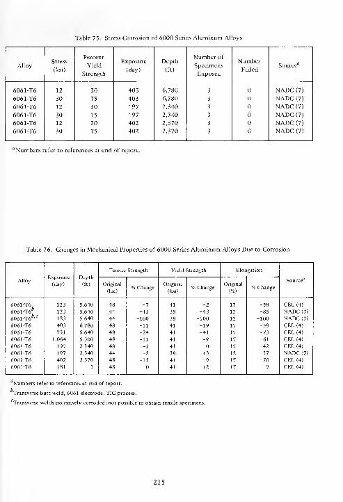
Table 75. Stress Corrosion of 6000 Series Aluminum Alloys
AlloyStress
(ksi)
Percent
Yield
Strength
Exposure
(day)
Depth
(ft)
Number of
Specimens
Exposed
Number
FailedSource
6061T66061-T6
6061-T6
6061-T6
6061-T6
6061-T6
12
30
12
30
12
30
30
75
30
75
30
75
403
403
197
197
402
402
6,780
6,780
2,340
2,340
2,370
2,370
3
3
3
3
3
3
NADC (7)
NADC (7)
NADC (7)
NADC (7)
NADC (7)
NADC (7)
"Numbers refer to references at end of report.
Table 76. Changes in Mechanical Properties of 6000 Series Aluminum Alloys Due to Corrosion
AlloyExposure
(day)
Depth
(ft)
Tensile Strength Yield Strength Elongation
SourceOriginal
(ksi)% Change
Original
(ksi)% Change
Original
(%)% Change
6061-T6
6061-T6*
6061-T6fc,C
6061 -T6
6061 -T6
6061 -T6
6061 -T6
6061-T6
6061-T6
6061 -T6
123
123
123
403
751
1,064
197
197
402
181
5,640
5,640
5,640
6,780
5,640
5,300
2,340
2,340
2,370
5
48
44
44
48
48
48
48
44
48
48
-7
-43
-100
-11
-24
-11
-5
-2
-15
41
38
38
41
41
41
41
38
41
41
-2
-43
-100
-19
-41
-9
+ 3
-9
+ 2
17
12
12
17
17
17
17
12
17
17
-58
-85
-100
-58
-73
-61
-42
-57
-70
-9
CEL (4)
NADC (7)
NADC (7)
CEL (4)
CEL (4)
CEL (4)
CEL (4)
NADC (7)
CEL (4)
CEL (4)
Numbers refer to references at end of report.
Transverse butt weld, 6061 electrode, TIG process.
Transverse welds excessively corroded; not possible to obtain tensile specimens.
215
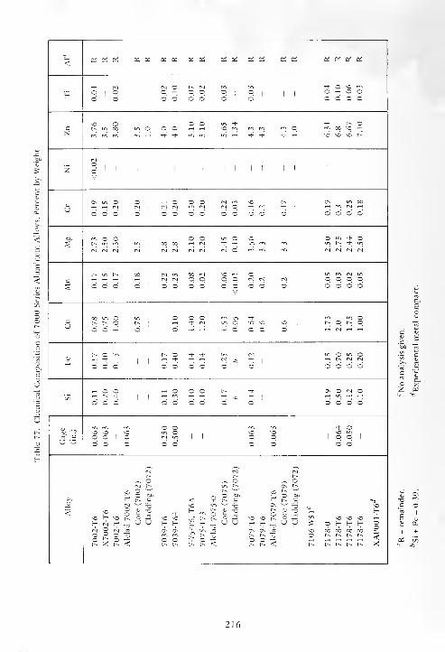
< Oh OS OS Oh Oh oi oS 0- Oh Oh OS Oh Oh Oh 0d Oi Oh Qi 0h
(N <s o t"~ IN „ m •* o \0'£* o 1 O
| |
o t-H o o ©I
©| | 1
o t-H s oo o o o © o o o o o © o
o o o Tf r~ oc c- in oo in o o o T-H t-H no m m m m o rv-i 00 VO t-H
m m m m 1-1 * •3- in in m T-( -=(- * + 1—1 ^O \o NO t-~
inO
ZV
0\ o o o o o (N no r^ CT\ oo
u ^H t-h rs) tN1
fNJ <M m (Nl (N © t-H CN t-H1
H «l (N t-H
o O o o o O o O o o O o O o O o
M o o o o o o d" or-- in
1
oo oo t-H IN Tt- t-H in m m1
in L*h Td" in
(N (N (N r-1 tN (N r-I r\l N o m m rn (N IN r-l r-J
t^ r^ on <N on <N \o O IN^H t-H T-H H <N (N o O o o IN cn] r-i . O o o o
S o o o O o o o o oV
o O o o o o o
00 o o o o M- ou r^ t"^ = r^
1 1
t-H -* CN in o NO NO •o|,
r^ o t^ oo o 1-1 o o 1-1 T"H T—l o O o ° 1—1 rj
t^ O t^ o rh •+ in o in ofc
T-H * t-H| 1
t-H >* t-H t-H IN T-H1 1
T-H t-~ (N (N
o o O o o o o o o O o o o
o o o O o r^ * On 3 oc/i
^ PnI Tt-| 1
T-H m t-H t-H ^H t-H1 1 1
^H in T-H T-H
o o o o © o o o o O O o o
m m m o o ^r oNO no no o vn no \0o o 1
~(N 1 1 o 1 o 1 o o 1
U ^=- o o o o o o o o o
(M (N (Nt-^ t-~ t-^
o o Or^ t-- K
o f> t^
o
-a <
no
o °1 t» c
on
oC 13
NO
< noH
V -a * H m r-- it T3 V -O T-H [_
nono
[•*- i- Q no \n NO NO£-, <N H TJ U U i-H H H o U u H H -o
U U ^ o H H H o(N <N| On 0\ On <T\ -o oo on on 00o o
t-~1-^ t^ r^ o r- r~ r^ f^ <o - O o o o -
t^ .>< t-~ <, t-^ t^ t-^ t^ < t-^ r^ <- t-^ r^ t-- r-- r~ X
216

ZZZUZUZZZZCiccuZU_, Q _, Q >. _,a < a < a aU Z u Z ai u
a a a a J J J
£ x
x * £i- * * ££a^- en a. .
O - a a- g «a '
-O cj
— ~ a.a X a a a a
a UU x \: X X X X x
a:a:<N_<Noooo
« —I <J
6 d ^I
V V
O O 3 O O
ooooooooo-i- X X X
o o o o o o oo oo ooooooot^t^ ^-Tt- + -t M » t t -t
« rt rt t)- *
SSJJS«SSS5^^"i s s s s t/3 S ^ ^cn^tn^^S
n 13 -a
^ 73 TJ
oocooooooocoooooc o *o p^ t~* p~ Is*
ooooocoooot^. p^ r^ t
ooooooooo <<<<<<<h h h hH f; f;
Os 6> 6> O* d\ On O^
ooooooo
217

bi-t--t--+ -t-t--i--t-t--t--+-t--t--+-+
S J J J J_1J_1J_J_J-JJJJuuuuuuuouuuuuuuuQQQQaQQQQQQQQQQQ<<<<<<<<<<<<<<<<zzzzzzzzzzzzzzzz
X XX X
V
a-_ w i Vc V V
j" ? ? x
u & ^ £
U. w u.X "- x-XV
S ti. ^ "V
a. x x y6" u
_ in _ O O _ O ^. __ OOOOOO
oc2:a:a:a:oso£or:^-]-j--+-:jaiQSC/3 ^ + C/3 c/3 Q, £u
OS Os Os Os t-^ t-. so so
OOOOOOOOO
r^t^rNcN osososos^-t^xxooxCs Os O O XXXXXXCSCS*t-+X Os On On O O O O
-I rf -I -3- -t •+ -t
S ;/> £ x J 5 »l X^ S' ^ ^^X^^^^^^X^X^X^X
T) TI
J -a a a
£ ? $ £ £ *
Tf .^ * * M- •& •t -+ •+ + Tt- <SO sn sn SO SO SO sn SO SO SO SO SO SO S.O
— E- t- t— h- H t- H t— fc— H h- H H t- H H HJs Cs Ov Os m Os Os OS Os Os Os Os Os Os
t^ r^ K r^O O O O O O O O O 'J O O O O
<sO so so
E— E— E—
^O \0 O *C "Of- <- S- r- t-
OOOO OOOOOOO
218
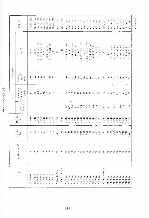
L> U U U U U U U 3-C CC222aa i
< <<<<<<< aZ ZZZZZZZ u
+*'* + J J J J J ^_J J J J _) >a b] a a a tii
u u u u u ^
i-UO-UC-C-'O —jQjQj-iDjuzuzuuz'o
^ ^ : —
0. X X r* _1 XX
C/3
n."
0.
aB."
Z Z ui=-
X X X•^ b. os Di .-. X B. B.
c a o - & a. £ a aa t« B. U a.
a. BC/) m
uOS K U w
Irl n.i I
J
u £;—
r X a: X X a: Xc/i
- d. •- — a. -._ b. ~ a. b. ~ o_
2 W °".Bi a "h bT
B. c/5 BJ cA C/5 BJ c/j
^T ,'C c/3•- ; cfl ,-:
*o x c\ o t^ no O O O O CN
o — * oc O » + -< «
o - o o c-t X x -i- -t
- c o o c o o o o o o o o o-t + MM^-^ + t^ ooooocoo
^-^t-ooooco^-^-oNCNOr-~r-~r^NONO«-i
O — -H -H
Jt/:Ji/iJ^!/i^ 3: 3: S w =S S 3:
o r^ r~^ c^- 1— r~^ \0 NO NO NO
r^ r^ t^ r~ r-. r~ r^O O 3 O O O O
CnCnCnOnCnC\CnC\C\On.OnO\OOOOOOOOOOOO
219

u CT r^ r^ r^ r~
u S"ouSSuuS3 _j>CQ_i_iQQ_iO aa<<aa<<uIJCiZZUUZZU
Sic3 4-.
E S-
„Sx,a OT "V XZ =: « 0'
X £ X^- - o. -
U £ M u—0.
2 6 Uii U
•* o o •+
O O '-' -J O *+
a t>
S S =2 £ .2" =5
t/j m en V) D S a
U X -J w tu; i/i u; « 3 5 X
ooooooooojj-rt-Tt-Tt-Tt-t^t^t^t^
cj c 3 3 S 5 m,
§ '5 S .s ° 3 ° SX £ £ J g Z Z £
= _2_lSZZa.
0\ Ov 0\ 0\ o o o o* tj- * •*
SSSwiJS"1 " ?
.>> '-3
wCQUQUWWOI u C T3
HHHHHHHHHOO0OX0OCO0OOO0O0O OUDUMUUI
220

Table 79. Stress Corrosion of 7000 Series Aluminum Alloys
AlloyStress
(ksi)
Percent
Yield
Strength
Exposure
(day)
Depth
(ft)
Number of
Specimens
Exposed
NumberFailed
Source1
7002-T6 18 30 403 6,780 3 NADC (7)
7002-T6 45 75 403 6,780 3 NADC (7)
7O02-T6 18 30 402 2,370 3 NADC (7)
7002-T6 30 50 402 2,370 3 CEL (4)
7002-T6 45 75 402 2,370 3 NADC (7)
7002-T6 45 75 402 2,370 3 CEL (4)
Alclad 7002-T6 18 30 403 6,780 3 NADC (7)
Alclad 7002-T6 45 75 403 6,780 3 NADC (7)
Alclad 7002-T6 18 30 402 2,370 3 NADC (7)
Alclad 7002-T6 29 50 402 2,370 3 CEL (4)
Alclad 7002-T6 45 75 402 2,370 3 NADC (7)
Alclad 7002-T6 43 75 402 2,370 3 CEL (4)
7075-T6 22 30 40 3 6,780 3 1 NADC (7)
7075-T6 55 75 403 6,780 3 b NADC (7)
7075-T6 22 30 197 2,340 3 NADC (7)
7075-T6 55 75 197 2,340 3 2 NADC (7)
7075-T6 22 30 402 2,370 3 NADC (7)
7075-T6 55 75 402 2,370 3 2 NADC (7)
7075-T6Ac
12 30 40 3 6,780 3 b NADC (7)
7075-T6At
30 75 403 6,780 3 b NADC (7)
7075-T6AC
12 30 197 2,340 3 NADC (7)
7075-T6Ac
30 75 197 2,340 3 NADC (7)
7075-T6AC
12 30 402 2,370 3 NADC (7)
7075-T6AC
30 75 402 2,370 3 NADC (7)
7075-T73 24 30 403 6,780 3 NADC (7)
7075-T73 51 75 403 6,780 3 NADC (7)
7075-T73 24 30 197 2,340 3 NADC (7)
707S-T73 51 75 197 2,340 3 NADC (7)
7075-T73 24 30 402 2,370 3 NADC (7)
7075-T73 51 75 402 2,370 3 NADC (7)
7079-T6 34 50 402 2,370 3 2 CEL (4)
7079-T6 50 75 402 2,370 3 3 CEL (4)
Alclad 7079-T6 35 50 402 2,370 3 1 CEL (4)
Alclad 7079-T6 53 75 402 2,370 3 2 CEL (4)
7178-T6 19 30 403 6,780 3 NADC (7)
7178-T6 49 75 403 6,780 3 b NADC (7)
7178-T6 19 30 197 2,340 3 NADC (7)
7178-T6 49 75 197 2,340 3 NADC (7)
7178-T6 19 30 402 2,370 3 NADC (7)
7178-T6 41 50 402 2,370 3 CEL (4)
7178-T6 49 75 402 2,370 3 3 NADC (7)
7178-T6 61 75 402 2,370 3 3 CEL (4)
XAP001-T6 6 30 403 6,780 3 b NADC (7)
I XAP001-T6 15 75 403 6,780 3 NADC (7)
' Numbers refer to references at end of report.
Missing when STU was recovered.
'Alloy 7076-T6 heated 8 hours at 350°F, air cooled.
221
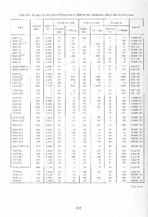
Table 80. Changes in Mechanical Properties of 7000 Series Aluminum Alloys Due to Corrosion
Depth
(ft)
Tensile Strength Yield Strength Elongation
AlloyExposure
(day) Original
(ksi)% Change
Original
(ksi)% Change
Original
(%)% Change
,, 17
Source
7002-T6 123 5,640 76 -10 68 -12 12 -8 NADC (7)
7002-T6fc
123 5,640 33 -32 - - 2 -100 NADC (7)
7002-T6fo,C,rf
123 5,640 - -100 - -100 - -100 NADC (7)
7002-T6 403 6,780 70 -62 58 -71 14 -91 CEL (4)
7002-T6 403 6,780 76 -12 68 -15 12 -8 NADC (7)
7002-T6 751 5,640 76 -8 68 -12 12 + 17 NADC (7)
7002-T6fc,</
197 2,340 - -100 - -100 - -100 NADC (7)
7002-T6 402 2,370 70 -1 58 14 CEL (4)
7002-T6 402 2,370 76 -10 68 -16 12 -14 NADC (7)
Alclad 7002-T6 403 6,780 65 -1 54 + 3 15 -14 CEL (4)
Alclad 7002-T6 402 2,370 65 -3 54 15 -10 CEL (4)
7039-T6 123 5,640 69 -4 60 -3 14 -16 CEL (4)
7039-T6 403 6,780 69 -100 60 - 1 00 14 -100 CEL (4)
7039 T6 rf751 5,640 69 -100 60 -100 14 -100 CEL (4)
7039-T6 197 2,340 69 -2 60 -2 14 -2 CEL (4)
7(>39-T6d
402 2,370 69 -100 60 -100 14 -100 CEL (4)
7039-T64 181 5 63 + 2 53 + 6 16 + 13 CEL (4)
7039-T64* 181 5 63 + 17 5 3 +4 16 +67 CEL (4)
7075-T6 123 5,640 83 76 + 1 11 -5 NADC (7)
7075-T6 403 6,780 83 -37 76 -28 1 1 -94 NADC (7)
7075-T6 751 5,640 83 -13 76 -9 11 -84 NADC (7)
7075-T6 1,064 5,300 83 -13 76 -10 11 -52 NADC (7)
7075-T6 197 2,340 83 -8 76 -4 11 -55 NADC (7)
7075-T6 402 2,370 83 -20 76 " 11 -91 NADC (7)
7075-T6A^ 197 2,340 71 -22 61 -18 10 -10 NADC (7)
7075-T6A^ 402 2,370 71 + 7 61 -10 10 -20 NADC (7)
7075-T64 123 5,640 71 -41 61 -31 10 -100 NADC (7)
7075-T73 123 5,640 72 62 10 + 10 NADC (7)
7075-T73 403 6,780 72 -11 62 -3 10 -75 NADC (7)
7075-T73 751 5,640 72 -8 62 -8 10 NADC (7)
7075-T73 197 2,340 72 -3 62 10 + 10 NADC (7)
7075-T73 402 2,370 72 62 +9 10 -70 NADC (7)
Akiad 7075-T6 123 5,640 76 68 10 -10 NADC (7)
7079-T6 123 5,640 76 -66 67 -63 11 -74 CEL (4)
7079-T6 403 6,780 76 -43 67 -52 11 -70 CEL (4)
7079-T6rf
751 5,640 76 -100 67 -100 11 -100 CEL (4)
7079-T6 197 2,340 76 -17 67 -4 11 -23 CEL (4)
7079T6 402 2,370 76 -1 67 11 -22 CEL (4)
Alclad 7079-T6 402 2,370 78 -2 69 -1 12 +4 CEL (4)
7178-T6 123 5,640 88 -19 80 -16 10 -16 CEL (4)
7178-T6 g 123 5,640 89 -49 65 - 11 -91 NADC (7)
7178-T6 403 6,780 88 -41 80 -41 10 -82 CEL (4)
7178-T6 40 3 6,780 89 -56 65 - 11 -91 NADC (7)
222
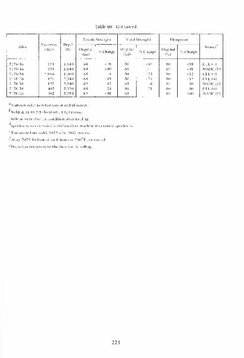
Table 80. Continued.
Tensile Strength Yield Strength Elongation
AlloyExposure
(day)
Depth
(ft)Source
Original
(ksi)% Change
Original
(ksi)% Change
Original
(%>% Change
7178-T6 751 5,640 88 -48 80 -64 10 -58 CEL (4)
7178-T6 751 5,640 89 -90 65 - 11 -91 NADC (7)
7178-T6 1,064 5,300 88 -4 80 -33 10 + 12 CEL (4)
7178-T6 197 2,340 88 -19 80 -37 10 -52 CEL (4)
7178-T6 197 2,340 89 -17 65 11 -10 NADC (7)
7178-T6 402 2,370 88 -24 80 -21 10 -80 CEL (4)
7178-T6 402 2,370 89 -58 65 " 11 -100 NADC (7)
' Numbers refer to references at end of report.
^Welded, MDR 7-5 electrode, TIG process.
Reheat treated to T6 condition after welding.
Specimens too corroded (exfoliated) to machine into tensile specimens.
'Transverse butt weld, 7039 wire, MIG process.
^ Alloy 7075-T6 heated for 8 hours at 350°F, air cooled.
^Properties transverse to the direction of rolling.
223


SECTION 7
TITANIUM ALLOYS
Titanium and titanium alloys owe their corrosion
resistance to a protective oxide film. This film resists
attack by oxidizing solutions, in particular those con-
taining chloride ions. It has outstanding resistance to
corrosion and pitting in marine environments and
other chloride salt solutions.
The chemical compositions of the titanium alloys
are given in Table 81, their corrosion rates and types
of corrosion in Table 82, their susceptibility to stress
corrosion in Table 83, and the effects of exposure on
their mechanical properties in Table 84.
7.1. CORROSION
The corrosion rates and type of corrosion of the
titanium alloys are given in Table 82.
Except for two alloys, there was no corrosion of
any of the titanium alloys during exposures in surface
seawater or at depths of 2,500 and 6,000 feet.
Reference 15 reported a corrosion rate of 0.19 mpyfor unalloyed titanium and of 0.18 mpy for 6A1-4V
after 123 days of exposure at the 6,000-foot depth,
but no corrosion of these same alloys after 75 1 days
of exposure at the 6,000-foot depth. Also, no visible
corrosion was reported. For practical purposes these
values are considered to be inconsequential.
DeLuccia, Reference 17, reported cracking in the
heat-affected zone parallel to the weld bead in alloy
6A1-4V after 197 days of exposure at the 2,500-foot
depth. Investigation of the weldments showed that
the welds had been made under improper conditions
and were contaminated with oxygen which made
them brittle.
Alloys 75A, 0.15Pd, 5Al-2.5Sn, 6A1-4V,
7Al-2Cb-lTa, 6Al-2Cb-lTa-lMo, and 13V-llCr-3Al
were both unwelded and welded. They were fusion-
welded by the inert-gas shielded arc, nonconsumable
tungsten electrode process (TIG). There were trans-
verse butt welds across the 6-inch dimension of the
specimens and 3-inch-diameter ring welds in the
centers of 6 x 12-inch specimens. The welded speci-
mens were intentionally not stress relieved in order to
simulate the conditions present in a welded structure,
i.e., to retain the maximum residual internal welding
stresses. The process of placing a circular weld in a
specimen imposes very high residual stresses in the
specimen. Such circular welds simulate multiaxial
stresses imposed in structures or parts fabricated by
welding. There was no visible corrosion of these
welded alloys except for stress corrosion cracking of
alloy 13V-llCr-3Al. This will be discussed under 7.2.
Alloy 6A1-4V was also exposed as:
(l)Wire, 0.020- 0.045-
diameter.
and 0.063-inch
(2)Cables, 1/16-inch (1x19), 1/4-inch
(6x19), 1/4-inch (6x19) with Type 304
stainless steel swaged ends, and 1/4-inch
(6 x 19) with ends tied with mild steel wire.
(3) Flash-welded tube.
(4) Flash-welded sphere.
(5) Piece from broken sphere.
(6) Welded rings 9.625-inch OD x 1.125-inch
wide x 8.75-inch ID. One ring was unstressed
and the others were stressed up to a maxi-
mum of 60,000 psi.
There was no visible corrosion on any of the above
specimens except for the AISI Type 304 swaged
fittings and the mild steel wire. The faying surfaces of
the Type 304 stainless steel fittings were severely
attacked by crevice corrosion. The rate of this crevice
corrosion was probably increased by the galvanic
couple formed by the two dissimilar metals, with the
stainless steel being the anode of the couple. The mild
steel wire used to tie the end of one titanium cable
was corroded almost through by galvanic corrosion;
the mild steel wire was anodic to the titanium cable.
7.2. STRESS CORROSION
Specimens of the alloys were stressed in various
ways and to values equivalent to 30, 35, 50, and 75%
225

of their respective yield strengths at the surface and
at depths of 2,500 and 6,000 feet for different
periods of time.
The majority of the specimens were deformed by
bowing to obtain the desired tensile stress in the
central 2-inch length of the outer surface of the
specimen. Many of these specimens, butt-welded by
the TIG process, were positioned such that the trans-
verse weld bead was at the apex of the bow in the
2-inch length. Other specimens, 6 x 12-inch, had a
3-inch-diameter circular weld bead placed in the
center. The stresses induced by the welding operation
were not relieved in order to retain the maximumresidua] stresses in the specimens. Still other speci-
mens were in the shape of welded rings, 9-5/8 inches
outside diameter, which were deformed different
amounts in order to induce tensile stresses in the
periphery at the ends of the restraining rods.
The results of the stress corrosion tests are given
in Table 83. There were no stress corrosion cracking
failures of any of the alloys, both unwelded and
butt-welded, stressed at values equivalent to as high as
75% of their respective yield strengths for 180 days
of exposure at the surface, 402 days at the 2,500-foot
depth, and 751 days at the 6,000-foot depth, except
for the butt-welded 13V-llCr-3Al alloy. The
unrelieved butt-welded 13V-llCr-3Al alloy failed by
stress corrosion cracking when stressed at values equi-
valent to 75% (94,500 psi) of its yield strength after
35, 77, and 105 days of exposure at the surface in the
Pacific Ocean. The stress corrosion cracks were in the
heat-affected zones at the edges of and parallel to the
weld beads.
The butt-welded 6 x 12-inch specimens of
13-V-llCr-3Al alloy failed by stress corrosion during
398, 540, and 588 days of exposure at the surface
due to the unrelieved residual welding stresses. The
stress corrosion cracks were perpendicular to and
extended across the weld beads from side to side.
The 6A1-4V alloy rings stressed as high as 60,000
psi (approximately 50% of its yield strength) did not
fail by stress corrosion cracking during 402 days of
exposure at the 2,500-foot depth.
Alloys 75A, O.lSPd, 5Al-2.5Sn, 7Al-2Cb-lTa,
6Al-2Cb-lTa-lMo, 6A1-4V, and 13V-1103A1 were
exposed with an unrelieved 3-inch-diameter circular
weld bead in the center of 6 x 12-inch specimens.
Only the 13V-llCr-3Al alloy failed by stress corro-
sion cracking because of the residual welding stresses.
Failure by stress corrosion cracking occurred first
after 181 days of exposure at the surface. Thereafter,
failures first occurred during 189 days of exposure
when partially embedded in the bottom sediments
and during 751 days of exposure in the seawater at
the 6,000-foot depth. At the 2,500-foot depth the
first failure occurred during 402 days of exposure in
the seawater. The cracks in all cases extended radially
across the weld beads. In some cases, the cracks
changed direction by 90% and propagated circumfer-
entially around the outside of the weld bead. In
general, the 13V-llCr-3Al alloy was more susceptible
to stress corrosion cracking in seawater at the surface
than at depth in the Pacific Ocean.
7.3. MECHANICAL PROPERTIES
The effects of exposure in seawater on the
mechanical properties of the titanium alloys are given
in Table 84. The mechanical properties of the
titanium alloys were not adversely affected.
226
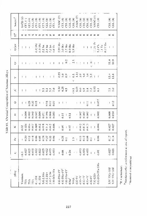
Q-^ t-~ t-~ t-~
^ -H- Tt" Tf -+ ^f Tl- -t * •* U Th ^+ M- -t u * -1- * T+ u * * *oo2
3O J j ^J J J J J J J
<c-J J J J
<J J J hJ -
<-J J J
w a HH w W ^ w ^ W W tu W W w w w w w u uu u u u u u u U u 2 U u U U z u u u u 2. o U <J
H OS B5 bj es tf oS p^ OS * OS OS OS OS OS OS oS OS OS Pfj OS OS OS OS OS
J31 1
T3Bj
T3EX
00cGO
coo H
oo o c o
1 1 1 1 1U H ^. 1 1
oo o «
t*>
IN Mo ON
CM
o r- ooo
ON^
rg th t^
(N t-H O
cm rt *d- ONu.
, , , ,
. . o1
(N .
1 o t-h OuV
ON o ON ^ «ON o o cs -+ vo
> 1 ' 1 1 1 1 1 1 1o O 1 o
V
* Th *1 1
cr> rr-i
o_l t-H t-H t-H o m CM in t-H *o o ON 00 (N ON T-H tH O< 1 1 1 1 in in in t> * Tj" ^ o
Vin \o in in r^ in ^O mm
r-
o oo IN on r-- r> r-1 1 fM 1 1 o 1 1 1 1 1 1 1 1 1 1 o
C o o o o o o o o
+ -+ *-> on ^ r^ t^ IN 00 O-. n o n © - ~ ~ o o O T-l
~1 - 3 o s o O a c o 1
T-
1
1T-H
1 1
~ C o 1 1 o o oo O o o o O o o o O o o o o o o o
XO \o r~ ON <N "+ VO m ^o r>. r>.
t-^ oo o o o c o z. o o ~
1 o 1 © 1 1 o c O 1 1 o o oo o ° o o — © o © o o ° o O o © o
o Tt- so -d- r~ \n m on ^o t-~ •*
OJ C-l ^H t-1
~ c rn (N rr>-
CM t-H ON t-H t-h o t-H o T-H ^H
to 1 ° o o o ° o O o 1 o O 1 1-1 1 o O o o 1 o o o
f^ N <s IN t~~ T^<N (N <N IN fM <N IN IN oo o <N IN <N tN (S
u T-H o o o o o o o O o|
o (N1
o O o|
o © Oo o o o o o o o o o o o o O o o O ©V
s
- > > > H< <
< £ C/3 J-.UJ O o o U U
- 7J T3 w;
u?
u > w > > > > > > > > IN U t-H ^H
<n (N N rr> -f -t *h Th •* -t- IN*f «f <1* > >
.ti in m "? ^ < < < < < < < > -t < < < < < < <r~ r-~ f- o O m in in t-^ * •* THT oo o VO VO VO vO t-~ vO
227

Table 82. Corrosion Rates and Types of Corrosion of Titanium Alloys
Corrosion
Alloy Environment'7Exposure
(day)
Depth
(ft)Source^
Rate
(mpy)Type*
Titanium W 123 5,640 <0.1 NC INCO(3)Titanium W 123 5,640 0.19 NC MEL (5)
Titanium S 123 5,640 <0.1 NC INCO(3)Titanium W 403 6,780 <0.1 NC INCO(3)
Titanium S 403 6,780 <0.1 NC INCO(3)Titanium W 751 5,640 <0.1 NC INCO(3)Titanium W 751 5,640 <0.1 NC MEL (5)
Titanium S 751 5,640 <0.1 NC INCO(3)Titanium W 1,064 5,300 <0.1 NC INCO(3)Titanium S 1,064 5,300 <0.1 NC INCO(3)Titanium W 197 2,340 <0.1 NC INCO(3)Titanium W 197 2,340 <0.1 NC Boeing (6)
Titanium s 197 2,340 <0.1 NC INCO(3)Titanium w 402 2,370 <0.1 NC INCO(3)Titanium s 402 2,370 <0.1 NC INCO(3)Titanium w 181 5 <0.1 NC INCO(3)Titanium w 366 5 <0.1 NC INCO(3)
75A w 123 5,640 0.0 NC CEL (4)
75A s 123 5,640 0.0 NC CEL (4)
75Ad w 189 5,900 0.0 NC CEL (4)
75Ae w 189 5,900 0.0 NC CEL (4)
75Arf
s 189 5,900 0.0 NC;BD CEL (4)
75Aes 189 5,900 0.0 NC;BD CEL (4)
75A w 403 6,780 0.0 NC CEL (4)
75A s 403 6,780 0.0 NC CEL (4)
75A w 751 5,640 0.0 NC CEL (4)
75A w 197 2,340 0.0 NC CEL (4)
75A s 197 2,340 0.0 NC CEL (4)
75A w 402 2,370 0.0 NC CEL (4)
75A s 402 2,370 0.0 NC CEL (4)
75A w 181 5 0.0 NC; FS CEL (4)
75A<V w 181 5 0.0 NC; FS CEL (4)
75A* w 181 5 0.0 NC; FS CEL (4)
75A w 398 5 0.0 NC CEL (4)
75A rf w 398 5 0.0 NC CEL (4)
75A? w 398 5 0.0 NC CEL (4)
75A w 540 5 0.0 NC CEL (4)
75Arf w 540 5 0.0 NC CEL (4)
75A* w 540 5 0.0 NC CEL (4)
Continued
228
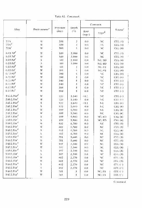
Table 82. Continued.
Corrosion
Alloy Environment'7Exposure
(day)
Depth
(ft)Source6
Rate
(mpy)Type6
75A W 588 5 0.0 NC CEL (4)
75A'V W 588 5 0.0 NC CEL (4)
75A l? W 588 5 0.0 NC CEL (4)
0.15 PdJ w 189 5,900 0.0 NC CEL (4)
0.15 Pd* w 189 5,900 0.0 NC CEL (4)
0.15 Pdrf
s 189 5,900 0.0 NC; BD CEL (4)
0.15 Pdes 189 5,900 0.0 NC; BD CEL (4)
0.15 Pd'^ w 181 5 0.0 NC; FS CEL (4)
0.15 Pd? w 181 5 0.0 NC;FS CEL (4)
0.15 ?dd w 398 5 0.0 NC CEL (4)
0.15 Pd'' w 398 5 0.0 NC CEL (4)
0.15 Pd rf w 540 5 0.0 NC CEL (4)
0.15 Pd* w 540 5 0.0 NC CEL (4)
0.15 Pd'f w 588 5 0.0 NC CEL (4)
0.15 Pd* w 588 5 0.0 NC CEL (4)
5Al-2.5Snrf w 123 5,640 <0.1 NC CEL (4)
5AI-2.5Sne w 123 5,640 0.0 NC CEL (4)
5Al-2.5Snd
s 123 5,640 <0.1 NC CEL (4)
5Al-2.5Sne
s 123 5,640 0.0 NC CEL (4)
5Al-2.5SnJ w 189 5,900 0.0 NC CEL (4)
5Al-2.5Sn* w 189 5,900 0.0 NC CEL (4)
5Al-2.5Sn'' s 189 5,900 0.0 NC; BD CEL (4)
5Al-2.5Sne
s 189 5,900 0.0 NC; BD CEL (4)
5Al-2.5Snd w 403 6,780 0.0 NC CEL (4)
5Al-2.5Sne w 403 6,780 0.0 NC CEL (4)
5Al-2.5Snrf
s 403 6,780 0.0 NC CEL (4)
5Al-2.5Sne
s 403 6,780 0.0 NC CEL (4)
5AI-2.5Snd w 751 5,640 0.0 NC CEL (4)
5Al-2.5Sne w 751 5,640 0.0 NC CEL (4)
5Al-2.5Snd w 197 2,340 0.0 NC CEL (4)
5Al-2.5Sn? w 197 2,340 0.0 NC CEL (4)
5Al-2.5Snrf
s 197 2.340 0.0 NC CEL (4)
5Al-2.5Snf
s 197 2,340 0.0 NC CEL (4)
5Al-2.5Snd w 402 2,370 0.0 NC CEL (4)
5Al-2.5Sn* w 402 2,370 0.0 NC CEL (4)
5Al-2.5SnJ
s 402 2,370 0.0 NC CEL (4)
5Al-2.5Sne
s 402 2,370 0.0 NC CEL (4)
5Al-2.5Snrf w 181 5 0.0 NC; FS CEL (4)
5Al-2.5Sne w 181 5 0.0 NC; FS CEL (4)
Continued
229
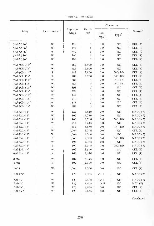
Table 82. Continued.
Depth
(ft)
Corrosion
Alloy Environment"Exposure
(day) Rate
(mpy)Type
Source6
5Al-2.5Snrf W 398 5 0.0 NC CEL (4)
5A1-2.5SI1* W 398 5 0.0 NC CEL(4)
5Al-2.5SnJ w 540 5 0.0 NC CEL (4)
5Al-2.5Sn? w 540 5 0.0 NC CEL (4)
5Al-2.5SntV w 588 5 0.0 NC CEL (4)
7Al-2Cb-lTarf w 189 5,900 0.0 NC CEL (4)
7Al-2Cb-lTae w 189 5,900 0.0 NC CEL (4)
7Al-2Cb-lTarf
s 189 5,900 0.0 NC; BD CEL (4)
7Al-2Cb-lTa'?
s 189 5,900 0.0 NC; BD CEL (4)
7Al-2Cb-lTa'y w 181 5 0.0 NC; FS CEL (4)
7Al-2Cb-lTa6
' w 181 5 0.0 NC;FS CEL (4)
7Al-2Cb-lTarf w 398 5 0.0 NC CEL (4)
7Al-2Cb-lTae w 398 5 0.0 NC CEL (4)
7Al-2Cb-lTad w 540 5 0.0 NC CEL (4)
7Al-2Cb-lTai? w 540 5 0.0 NC CEL (4)
7Al-2Cb-lTarf w 588 5 0.0 NC CEL (4)
7Al-2Cb-lTae w 588 5 0.0 NC CEL (4)
4A1-3MO-1V w 123 5,640 0.0 NC NADC (7)
4AI-3Mo-lV w 403 6,780 0.0 NC NADC (7)
4A1-3M0-1V s 403 6,780 0.0 NC; BD NADC (7)
4Al-3Mo-lV w 751 5,640 0.0 NC NADC (7)
4Al-3Mo-lV s 751 5,640 0.0 NC; BD NADC (7)
4Al-3Mo-lV w 1,064 5,300 0.0 NC CEL (4)
4Al- 3Mo-IV w 1,064 5,300 0.0 NC NADC (7)
4Al-3Mo-lV s 1,064 5,300 0.0 NC; BD NADC (7)
4A1-3MO-1V w 197 2,340 0.0 NC NADC (7)
4A1-3MO-1V s 197 2,340 0.0 NC; BD NADC (7)
4A1-3MO-1V w 402 2,370 0.0 NC CEL (4)
4A1-3MO-1V s 402 2,370 0.0 NC CEL (4)
8'Mn w 402 2,370 0.0 NC CEL (4)
8 Mn s 402 2,370 0.0 NC CEL (4)
140A w 1,064 5,300 0.0 NC CEL (4)
7Al-12Zr w 123 5,300 <0.1 NC NADC (7)
6A1-4V w 123 5,640 <0.1 NC NADC (7)
6A1-4V w 123 5,640 0.18 NC MEL (5)
6A1-4V w 123 5,640 0.0 NC CEL (4)
6AI-4V* w 123 5,640 0.0 NC CEL (4)
Continued
230
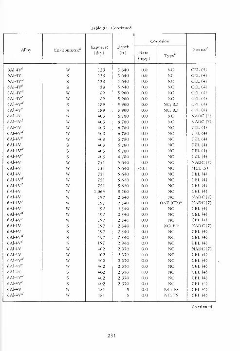
Table 82. Continued.
Co rrosion
Alloy Environment''Exposure
(day)
Depth
(ft) Rate
(mpy)Type*
Source1
6Al-4Ve W 123 5,640 0.0 NC CEL (4)
6A1-4V S 123 5,640 0.0 NC CEL (4)
6A1-4VJ S 123 5,640 0.0 NC CEL (4)
6A1-4V S 123 5,640 0.0 NC CEL (4)
6Al-4Vrf w 189 5,900 0.0 NC CEL (4)
6Al-4Vf w 189 5,900 0.0 NC CEL (4)
6Al-4V rf
s 189 5,900 0.0 NC; BD CEL (4)
6A1-4V* s 189 5,900 0.0 NC; BD CEL (4)
6A1-4V w 403 6,780 0.0 NC NADC (7)
6A1-4V^ w 403 6,780 0.0 NC NADC (7)
6A1-4V w 403 6,780 0.0 NC CEL (4)
6Al-4V rf w 403 6,780 0.0 NC CEL (4)
6A1-4V' w 403 6,780 0.0 NC CEL (4)
6A1-4V s 403 6,780 0.0 NC CEL (4)
6Al-4V rf
s 403 6,780 0.0 NC CEL (4)
6Al-4Ve s 403 6,780 0.0 NC CEL (4)
6A1-4V w 751 5,640 0.0 NC NADC (7)
6A1-4V w 751 5,640 <0.1 NC MEL (5)
6A1-4V w 751 5,640 0.0 NC CEL (4)
6Al-4Vd w 751 5,640 0.0 NC CEL (4)
6A1-We w 751 5,640 0.0 NC CEL (4)
6A1-4V w 1,064 5,300 0.0 NC CEL (4)
6A1-4V w 197 2,340 0.0 NC NADC (7)
6Al-4V-f w 197 2,340 0.0 HAZ (CR) g NADC (7)
6A1-4V w 197 2,340 0.0 NC CEL (4)
6Al-4V rf w 197 2,340 0.0 NC CEL (4)
6A1-4V2 w 197 2,340 0.0 NC CEL (4)
6A1-4V s 197 2,340 0.0 NC; BD NADC (7)
6A1-4V s 197 2,340 0.0 NC CEL (4)
6Al-4Vd s 197 2,340 0.0 NC CEL (4)
6Al-4Ves 197 2,340 0.0 NC CEL (4)
6A1-4V w 402 2,370 0.0 NC NADC (7)
6A1-4V w 402 2,370 0.0 NC CEL (4)
6Al-4V rf w 402 2,370 0.0 NC CEL (4)
6A1-4V* w 402 2,370 0.0 NC CEL (4)
6A1-4V s 402 2,370 0.0 NC CEL (4)
6AJ-4V rfs 402 2,370 0.0 NC CEL (4)
6Al-4Ves 402 2,370 0.0 NC CEL (4)
6A1-4V w 181 5 0.0 NC: FS CEL (4)
6A1-4V'' w 181 5 0.0 NC; FS CEL (4)
Continued
231
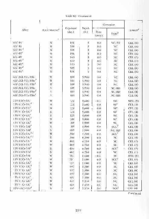
Table 82. Continued.
Exposure
(day)
Depth
(ft)
Corrosion
Alloy Environment''Rate
(mpy)rr bType
Source6
6A1-4V* W 181 5 0.0 NC; FS CEL (4)
6A1-4V W 398 5 0.0 NC CEL (4)
6A1-4V"' W 398 5 0.0 NC CEL (4)
6A1-4V W 398 5 0.0 NC CEL (4)
6A1-4V W 540 5 0.0 NC CEL (4)
6Al-4V rf W 540 5 0.0 NC CEL (4)
6A1-4V* w 540 5 0.0 NC CEL (4)
6Al-4V'f w 588 5 0.0 NC CEL (4)
6Al-4Ve w 588 5 0.0 NC CEL (4)
6Al-2Cb-lTa-lMo w 189 5,900 0.0 NC CEL (4)
6Al-2Cb-lTa-lMo rf w 189 5,900 0.0 NC CEL (4)
6Al-2Cb-lTa-lMo'? w 189 5,900 0.0 NC CEL (4)
6Al-2Cb-lTa-lMo s 189 5,900 0.0 NC; BD CEL (4)
6Al-2Cb-nz-lMod s 189 5,900 0.0 NC;BD CEL (4)
6Al-2Cb-lTa-lMoes 189 5,900 0.0 NC; BD CEL (4)
13V-llCr-3Al w 123 5,640 <0.1 NC MEL (5)
13V-llCr-3Al rf w 123 5,640 0.0 NC CEL (4)
13V-llCr-3Af w 123 5,640 0.0 NC CEL (4)
13V-llCr-3Ald s 123 5,640 0.0 NC CEL (4)
13V-llCr-3Ale
s 123 5,640 0.0 NC CEL (4)
13V-llCr-3Ald w 189 5,900 0.0 NC CEL (4)
13V-llCr-3Ale w 189 5,900 0.0 NC CEL (4)
13V-llCt-3AlJ s 189 5,900 0.0 sec'-7 CEL (4)
13V-llCr-3Ales 189 5,900 0.0 NC; BD CEL (4)
13V-llCr-3Al'y '' w 360 4,200 0.0 SCC ; CEL (4)
13V-llCr-3Alrf-'
s 360 4,200 0.0 NC CEL (4)
13V-llCr-3Al'Y w 403 6,780 0.0 NC CEL (4)
13V-llCr-3Ale w 403 6,780 0.0 NC CEL (4)
13V-llCr-3Ald
s 403 6,780 0.0 SCC; CEL (4)
13V-llCr-3Ales 403 6,780 0.0 NC CEL (4)
13V-11&-3A1 w 751 5,640 <0.1 NC MEL (5)
13V-llCr-3Al rf w 751 5,640 0.0 sccy CEL (4)
13V-llCr-3Ale w 751 5,640 0.0 NC CEL (4)
13V-llCr-3Al rf w 197 2,340 0.0 NC CEL (4)
13V-llGr-3Ale w 197 2,340 0.0 NC CEL (4)
13V-llCr-3Al rf
s 197 2,340 0.0 NC CEL (4)
13V-llCr-3Al i'
s 197 2,340 0.0 NC CEL (4)
13V-llCr-3Al rf w 402 2,370 0.0 NC CEL (4)
13V-llCr-3Ale w 402 2,370 0.0 NC CEL (4)
13V-llCr-3Al rfs 402 2,370 0.0 scd CEL (4)
Continued
232
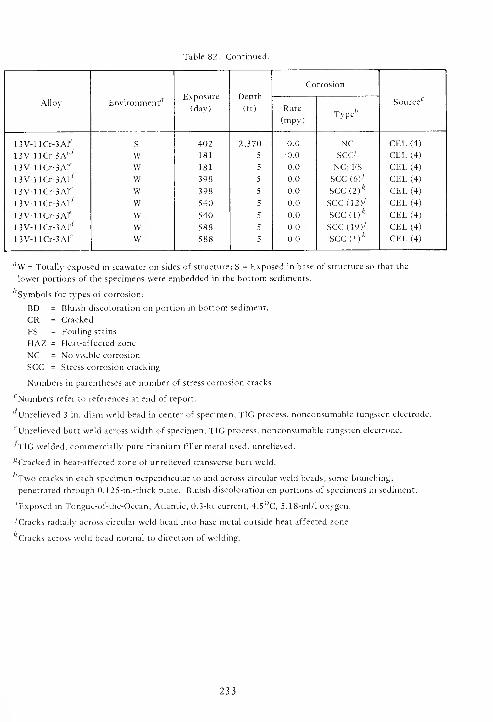
Table 82. Continued.
Alloy Environment'7Exposure
(day)
Depth
(ft)
Corrosion
Source17
Rate
(mpy)Type''
13V-llCr-3Al t'
13V-llCr-3Ald
13V-llCr-3Ale
13V-llCr-3Ald
13V-llCr-3Ale
13V-llCr-3Al'y
13V-llCr-3Ale
13V-llCr-3Ald
13V-llCr-3AIe
S
Wwwwwwww
402
181
181
398
398
540
540
588
588
2,370
5
5
5
5
5
5
5
0.0
0.0
0.0
0.0
0.0
0.0
0.0
0.0
0.0
NCsec'
NC; FS
sec (6)>
sec (2)*
SCC(12ySCC(l)*
SCC(19)7
seed)''
CEL (4)
CEL (4)
CEL (4)
CEL (4)
CEL (4)
CEL (4)
CEL (4)
CEL (4)
CEL (4)
flW = Totally exposed in seawater on sides of structure; S = Exposed in base of structure so that the
lower portions of the specimens were embedded in the bottom sediments.
Symbols for types of corrosion:
BD = Bluish discoloration on portion in bottom sediment.
CR = Cracked
FS = Fouling stains
HAZ = Heat-affected zone
NC = No visible corrosion
SCC = Stress corrosion cracking
Numbers in parentheses are number of stress corrosion cracks
' Numbers refer to references at end of report.
Unrelieved 3-in.-diam weld bead in center of specimen, TIG process, nonconsumable tungsten electrode.
eUnrelieved butt weld across width of specimen, TIG process, nonconsumable tungsten electrode.
'TIG welded, commercially pure titanium filler metal used, unrelieved.
^Cracked in heat-affected zone of unrelieved transverse butt weld.
Two cracks in each specimen perpendicular to and across circular weld beads; some branching;
penetrated through 0.125-in.-thick plate. Bluish discoloration on portions of specimens in sediment.
'Exposed in Tongue-of-the-Ocean, Atlantic, 0.3-kt current, 4.5°C, 5.18-ml/l oxygen.
•'Cracks radially across circular weld bead into base metal outside heat-affected zone.
Cracks across weld bead normal to direction of welding.
233
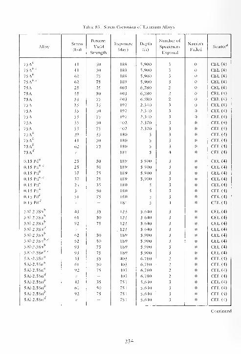
Table 83. Stress Corrosion of Titanium Alloys
AlloyStress
(ksi)
Percent
Yield
Strength
Exposure
(day)
Depth
(ft)
Number of
Specimens
Exposed
Number
FailedSource"
7 5 A'' 41 50 189 5,900 3 CEL (4)
75A fo 't'
41 50 189 5,900 3 CEL(4)
75A'' 62 75 189 5,900 3 CEL (4)
75A fc 't
'
62 75 189 5,900 3 CEL (4)
75A 25 35 403 6,780 2 CEL (4)
75A 35 50 403 6,780 2 CEL (4)
75A 53 75 403 6,780 2 CEL (4)
75A 25 35 197 2,340 3 CEL (4)
75A 35 50 197 2,340 3 CEL (4)
75A 53 75 197 2,340 3 CEL (4)
75A 35 50 402 2,370 3 CEL (4)
75A 53 75 402 2,370 3 CEL (4)
75A fo
29 35 180 5 3 CEL (4)
75A b41 50 180 5 3 CEL (4)
75A fo
62 75 180 5 3 CEL (4)
75A'V
e - 181 5 4 CEL (4)
0.15 Pd'7
25 50 189 5,900 3 CEL (4)
0.15 Pd fc'6
'
25 50 189 5,900 3 CEL (4)
0.15 Pd fo
37 75 189 5,900 3 CEL (4)
0.15 Pd fc'c
37 75 189 5,900 3 CEL (4)
0.15 Pd fo 24 35 180 5 3 CEL (4)
0.15 Pd fo
34 50 180 5 3 CEL (4)
0.15 Pd fc
51 75 180 5 3 CEL (4)
0.15 Pd'y
e - 181 5 4 CEL (4)
5Al-2.5Snfc
43 35 123 5,640 3 CEL (4)
5Al-2.5Sn fc
61 50 12 3 5,640 3 CEL (4)
5Al-2.5Snfo
92 75 123 5,640 3 CEL (4)
5Al-2.5Sn'' e -.123 5,640 3 CEL (4)
5Al-2.5Sn'' 62 50 189 5,900 3 CEL (4)
5Al-2.5Snfc ' c 62 50 189 5,900 3 CEL (4)
5Al-2.5Sn/7
93 75 189 5,900 3 CEL (4)
5Al-2.5Snfolt
'
93 75 189 5,900 3 CEL (4)
5Al-2.5Sn'' 43 35 403 6,780 2 CEL (4)
5Al-2.5Sn fc61 50 403 6,780 2 CEL (4)
5Al-2.5Sn ;' 92 75 403 6,780 2 CEL (4)
5Al-2.5SnJ
e - 403 6,780 2 CEL (4)
5Al-2.5Sn'' 43 35 751 5,640 3 CEL (4)
5Al-2.5Snfo
61 50 751 5,640 3 CEL (4)
5Al-2.5Sn'7
92 75 751 5,640 3 CEL (4)
5Al-2.5Snl/
e - 751 5,640 3 CEL (4)
Continued
234
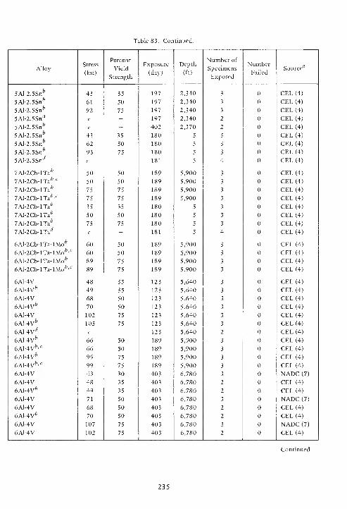
Table 83. Continued.
AlloyStress
(ksi)
Percent
Yield
Strength
Exposure
(day)
Depth
(ft)
Number of
Specimens
Exposed
Number
FailedSource'
7
5Al-2.5Snfo
43 35 197 2,340 3 CEL (4)
5Al-2.5Snfc
61 50 197 2,340 3 CEL (4)
5Al-2.5Snfc
92 75 197 2,340 3 CEL (4)
5Al-2.5Snrf
e - 197 2,340 2 CEL (4)
5Al-2.5Snfc
e - 402 2,370 2 CEL (4)
5Al-2.5Snfc
43 35 180 5 3 CEL (4)
5Al-2.5Snfc
62 50 180 5 3 CEL (4)
5Al-2.5Sn&
93 75 180 5 3 CEL (4)
5Al-2.5SnJ
e - 181 5 4 CEL (4)
7Al-2Cb-lTafc
50 50 189 5,900 3 CEL (4)
7Al-2Cb-lTafc '
<:
50 50 189 5,900 3 CEL (4)
7Al-2Cb-lTa fc75 75 189 5,900 3 CEL (4)
7Al-2Cb-lTa fo ' r 75 75 189 5,900 3 CEL (4)
7Al-2Cb-lTa fc
35 35 180 5 3 CEL (4)
7Al-2Cb-lTa& 50 50 180 5 3 CEL (4)
7Al-2Cb-lTafc
75 75 180 5 3 CEL (4)
7Al-2Cb-lTad
e - 181 5 4 CEL (4)
6Al-2Cb-lTa-lMo* 60 50 189 5,900 3 CEL (4)
6Al-2Cb-lTa-lMofcc60 50 189 5,900 3 CEL (4)
eAl^Cb-lTa-lMo6 89 75 189 5,900 3 CEL (4)
6Al-2Cb-lTa-lMo fo'c
89 75 189 5,900 3 CEL (4)
6A1-4V 48 35 123 5,640 3 CEL (4)
6A1-4V6 49 35 123 5,640 3 CEL (4)
6A1-4V 68 50 123 5,640 3 CEL (4)
6Al-4V fe
70 50 123 5,640 3 CEL (4)
6A1-4V 102 75 123 5,640 3 CEL (4)
6A1-4V* 105 75 123 5,640 3 CEL (4)
6Al-4V rfe - 123 5,640 2 CEL (4)
6A1-4V6 66 50 189 5,900 3 CEL (4)
6Al-4Vfr' c 66 50 189 5,900 3 CEL (4)
6Al-4V fc
99 75 189 5,900 3 CEL (4)
6Al-4V fo'c
99 75 189 5,900 3 CEL (4)
6A1-4V 43 30 403 6,780 3 NADC (7)
6A1-4V 48 35 403 6,780 2 CEL (4)
6A1-4V* 49 35 403 6,780 2 CEL (4)
6A1-4V 71 50 403 6,780 3 NADC (7)
6AJ-4V 68 50 403 6,780 2 CEL (4)
6Al-4V fo 70 50 403 6,780 2 CEL (4)
6A1-4V 107 75 403 6,780 3 NADC (7)
6AJ-4V 102 75 403 6,780 2 CEL (4)
Continued
235
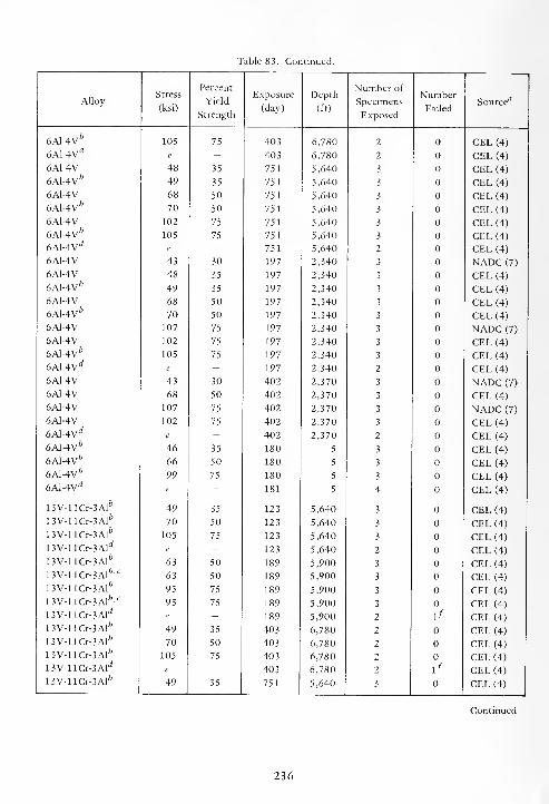
Table 83. Continued.
AlloyStress
(ksi)
Percent
Yield
Strength
Exposure
(day)
Depth
(ft)
Number of
Specimens
Exposed
Number
FailedSource'
7
6Al-4Vfc
105 75 403 6,780 2 CEL (4)
6Al-4Vrf
e - 403 6,780 2 CEL (4)
6A1-4V 48 35 751 5,640 3 CEL (4)
6A1-4V6
49 35 751 5,640 3 CEL (4)
6A1-4V 68 50 751 5,640 3 CEL (4)
6A1-4V* 70 50 751 5,640 3 CEL (4)
6A1-4V 102 75 751 5,640 3 CEL (4)
6Al-4Vfc
105 75 751 5,640 3 CEL (4)
6Al-4Vd e - 751 5,640 2 CEL (4)
6A1-4V 43 30 197 2,340 3 NADC (7)
6A1-4V 48 35 197 2,340 3 CEL (4)
6Al-4V fc
49 35 197 2,340 3 CEL (4)
6A1-4V 68 50 197 2,340 3 CEL (4)
6Al-4V fc
70 50 197 2,340 3 CEL (4)
6A1-4V 107 75 197 2,340 3 NADC (7)
6A1-4V 102 75 197 2,340 3 CEL (4)
6A1-4V* 105 75 197 2,340 3 CEL (4)
6Al-4V rfe - 197 2,340 2 CEL (4)
6A1-4V 43 30 402 2,370 3 NADC (7)
6A1-4V 68 50 402 2,370 3 CEL (4)
6A1-4V 107 75 402 2,370 3 NADC (7)
6A1-4V 102 75 402 2,370 3 CEL (4)
6Al-4V rfe - 402 2,370 2 CEL (4)
6Al-4V fe
46 35 180 5 3 CEL (4)
6Al-4V fc
66 50 180 5 3 CEL (4)
6Al-4V fc
99 75 180 5 3 CEL (4)
6Al-4V rfe - 181 5 4 CEL (4)
13V-llCr-3AIfc
49 35 123 5,640 3 CEL (4)
13V-llCr-3Alfc
70 50 123 5,640 3 CEL (4)
13V-llCr-3Alfo
105 75 123 5,640 3 CEL (4)
13V-llCr-3Alrf
e - 123 5,640 2 CEL (4)
13V-llCr-3Al&
63 50 189 5,900 3 CEL (4)
13V-llCr-3Alfc,c
63 50 189 5,900 3 CEL (4)
13V-llCr-3Alfc
95 75 189 5,900 3 CEL (4)
13V-llCr-3AIfc,<:
95 75 189 5,900 3 CEL (4)
13V-llCr-3Ald
e - 189 5,900 2 \f CEL (4)
13V-llCr-3Alfe
49 35 403 6,780 2 CEL (4)
13V-llCr-3Al fc
70 50 403 6,780 2 CEL (4)
13V-llCr-3Al& 105 75 403 6,780 2 CEL (4)
13V-llCr-3Ald e - 403 6,780 2 \f CEL (4)
13V-llCr-3Al fc
49 35 751 5,640 3 CEL (4)
Continued
236

Table 83. Continued.
AlloyStress
(ksi)
Percent
Yield
Strength
Exposure
(day)
Depth
(ft)
Number of
Specimens
Exposed
Number
FailedSource"
13V-llCr-3Alfo 70 50 751 5,640 3 CEL(4)
13V-llCr-3Al* 105 75 751 5,640 3 CEL (4)
13V-llCr-3Ald
e - 751 5,640 2 1* CEL (4)
13V-llCr-3Alfc
49 35 197 2,340 3 CEL (4)
13V-llCr-3Al&
70 50 197 2,340 3 CEL (4)
13V-llCr-3Alfo
105 75 197 2,340 3 CEL (4)
13V-llCr-3Ald
e - 197 2,340 3 CEL (4)
13V-llCr-3Ald
e - 402 2,370 2 \f CEL (4)
13V-llCr-3Alfc
44 35 180 5 3 CEL (4)
13V-llCr-3Alfc
63 50 180 5 3 CEL (4)
13V-llCr-3Alfc
95 75 180 5 3 3h CEL (4)
13V-llCr-3Ald
e - 181 5 4 1* CEL (4)
13V-llCr-3Alfo
e - 398 5 2 2' CEL (4)
13V-llCr-3Alrf
e - 398 5 2 2{ CEL (4)
13V-llCr-3Alfo
e - 540 5 2 1' CEL (4)
13V-llCr-3AlJ
e - 540 5 2 2k CEL (4)
13V-llCr-3Al fce - 588 5 2 1' CEL (4)
13V-llCr-3Ald
e - 588 5 2 2> CEL (4)
"Numbers refer to references at end of report.
Unrelieved butt weld across width of specimen, TIG process, nonconsumable tungsten electrode,
weld at apex of bow.
cPartially embedded in bottom sediment.
Unrelieved 3-in.-diam weld bead in center of specimen, TIG process, nonconsumable tungsten electrode.
'Residual welding stresses.
'Specimen partially embedded in bottom sediment; cracked radially across the weld bead.
^Specimen in seawater; cracked radially across the weld bead.
^Specimens failed in heat-affected zones after 35, 77, and 105 days of exposure.
'Cracks across weld beads.
•'Six cracks radially across weld beads.
Twelve cracks radially across weld beads.
Nineteen cracks radially across weld beads.
237
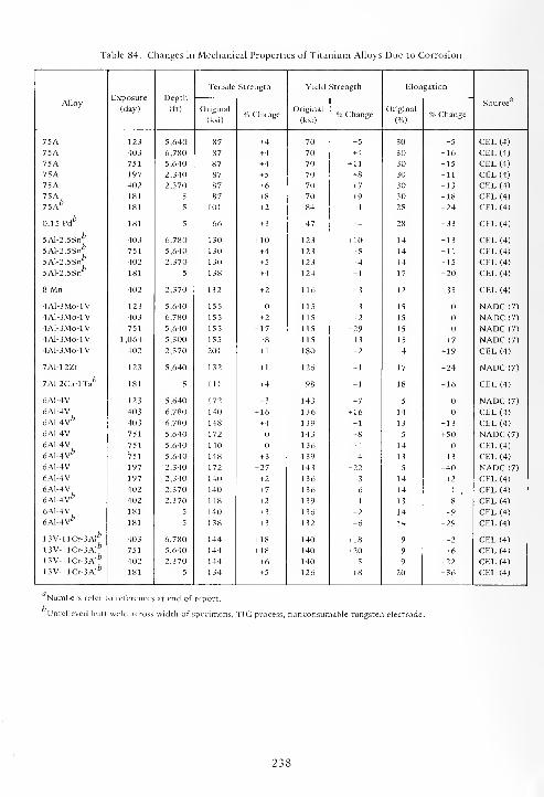
Table 84. Changes in Mechanical Properties of Titanium Alloys Due to Corrosion
Exposure
(day)
Depth
(ft)
Tensile Strength Yield Strength Elongation
AlloyOriginal
(ksi)% Change
Original
(ksi)% Change
Original
(%)% Change
Source
75A 123 5,640 87 +4 70 + 5 30 -5 CEL (4)
75A 403 6,780 87 +4 70 +4 30 -16 CEL(4)75A 751 5,640 87 +4 70 + 11 30 -15 CEL (4)
75A 197 2,340 87 + 5 70 +8 30 -11 CEL (4)
75A 402 2,370 87 +6 70 + 7 30 -13 CEL (4)
75A75A fe
181 5 87 +8 70 +9 30 -18 CEL (4)
181 5 101 + 2 84 -1 25 -24 CEL (4)
0.15 Pd* 181 5 66 + 3 47 +4 28 -33 CEL (4)
5Al-2.5Snfc
5Al-2.5Snfc
5Al-2.5Snb
5AI-2.5Snfe
403 6,780 130 + 10 123 + 10 14 -13 CEL (4)
751 5,640 130 + 4 123 + 5 14 -11 CEL (4)
402 2,370 130 + 5 123 +4 14 -15 CEL (4)
181 5 138 +4 124 + 1 17 -20 CEL (4)
8 Mn 402 2,370 132 + 2 116 + 3 12 + 33 CEL (4)
4A1-3MO-1V 123 5,640 155 115 -3 15 NADC (7)
4AI-3MO-1V 403 6,780 155 + 2 115 + 2 15 NADC (7)
4A1-3MO-1V 751 5,640 155 -17 115 -29 15 NADC (7)
4A1-3MO-1V 1,064 5,300 155 -8 115 -13 15 + 7 NADC (7)
4A1-3MO-1V 402 2,370 201 + 1 180 -2 4 + 19 CEL (4)
7Al-12Zr 123 5,640 132 + 1 126 + 1 17 -24 NADC (7)
7Al-2Cb-lTafo
181 5 111 +4 98 + 1 18 -16 CEL (4)
6A1-4V 123 5,640 172 -3 143 +7 5 NADC (7)
6A1-4V
6A1-4V*
403 6,780 140 + 16 136 + 16 14 CEL (4)
403 6,780 148 +4 139 -1 13 -13 CEL (4)
6A1-4V 751 5,640 172 143 +8 5 +50 NADC (7)
6A1-4V
6Al-4Vfc
751 5,640 140 136 +4 14 CEL (4)
751 5,640 148 + 3 139 +4 13 -13 CEL (4)
6A1-4V 197 2,340 172 -27 143 -22 5 -40 NADC (7)
6A1-4V 197 2,340 140 + 2 136 + 3 14 +2 CEL (4)
6A1-4V
6A1-4V*
402 2,370 140 + 7 136 +6 14 -1, CEL (4)
402 2,370 148 + 2 139 + 1 13 -8 CEL (4)
6A1-4V
6Al-4Vfc
181 5 140 + 3 136 + 2 14 -9 CEL (4)
181 5 138 + 3 132 -6 14 -29 CEL (4)
13V-llCr-3Alfo
13V-llCr-3Al fc
13V-llCr-3Alfo
13V-llCr-3Al fo
403 6,780 144 + 18 140 + 18 9 -2 CEL (4)
751 5,640 144 + 18 140 +20 9 +6 CEL (4)
402 2,370 144 +6 140 +5 9 -22 CEL (4)
181 ? 134 +5 126 +8 20 -36 CEL (4)
Numbers refer to references at end of report.',
Unrelieved butt weld across width of specimens, TIG process, nonconsumable tungsten electrode.
238

SECTION 8
MISCELLANEOUS ALLOYS
The miscellaneous alloys are those alloys or
metals which are "one of a kind" or do not belong to
any of the previous classes of alloys discussed. These
alloys would not be considered constructional
because of their price, mechanical properties,
scarcity, and, in some cases, poor corrosion resis-
tance. Many of them could be used advantageously in
specialty or unique applications.
The chemical compositions of the miscellaneous
alloys are given in Table 85, and their corrosion rates
and types of corrosion in Table 86.
Alloys columbium, gold, platinum, 90%
platinum-10% copper, 75% platinum- 25% copper,
tantalum, and tantalum-tungsten (Ta60) were
uncorroded during exposure both at depth and at the
surface.
Alloy MP35N neither corroded nor was suscep-
tible to stress corrosion during 189 days of exposure
at the 6,000-foot depth. The MP35N bolts and nuts
were in a block of 6A1-4V titanium and were torqued
to 50 ft-lb. There was also no galvanic corrosion of
either member of the couple.
The corrosion of the three magnesium alloys
(MIA, AZ31B, and HK31A) and beryllium was so
rapid that their use in seawater would be impractical.
Platinum alloys containing 50 and 75% copper
were etched and pitted after 402 days of exposure at
the 2,500-foot depth. Such alloys are usually used for
contacts in electrical applications. These two alloys
would not be satisfactory for use in seawater.
Silver was attacked by the uniform thinning type
of corrosion in seawater. The thin tarnish-like film is
an excellent insulator; hence, silver could not be used
as electrical contacts in seawater.
8.1. DURATION OF EXPOSURE
The effects of duration of exposure on some of
the miscellaneous alloys are shown in Figures 18, 19,
and 20. The corrosion rates of arsenical, chemical,
and tellurium lead, lead-tin solder, tin, and zinc
decreased with duration of exposure (Figures 18 and
19), except for lead-tin solder and zinc at the
2,500-foot depth. The corrosion rates of these two
alloys increased with increasing time of exposure. At
the 6,000-foot depth the corrosion rate of tin
increased initially, and, thereafter, decreased with
increasing time of exposure. The extremely high
corrosion rate for tin after 751 days of exposure
(Table 86), obviously, is an error and must be dis-
Only surface seawater data were available for
molybdenum and tungsten, and the effects of dura-
tion of exposure are shown in Figure 20. The
corrosion rate of molybdenum decreased, becoming
asymptotic with increasing time of exposure. The
corrosion rate of tungsten increased linearly with
time, at least during the first 760 days of exposure.
8.2. EFFECT OF DEPTH
The effects of depth on the corrosion of some of
the miscellaneous alloys after 1 year of exposure are
shown in Figure 21. The corrosion of lead, lead-tin
solder, molybdenum, tungsten, and tin was greater at
the surface than at depth in the Pacific Ocean. Only
the corrosion of zinc was greater at depth than at the
surface.
8.3. EFFECT OF CONCENTRATION OF OXYGEN
The effects of changes in the concentration of
oxygen in seawater are shown in Figure 22. The
corrosion rates of arsenical, chemical, and tellurium
lead, lead-tin solder, molybdenum, tungsten, and tin
were higher at the highest concentration of oxygen
than at the lowest, but the increases were not neces-
sarily proportional or linear. Only the corrosion of
zinc was not uniformly influenced by changes in the
concentration of oxygen in seawater between the
limits of 0.4 to 5.75 ml/1.
239
8.4. MECHANICAL PROPERTIES
The effects of exposure on the mechanical pro-
perties of columbium, molybdenum, and tantalum
are given in Table 87. The mechanical properties of
these three alloys were not impaired by exposure in
seawater.
240
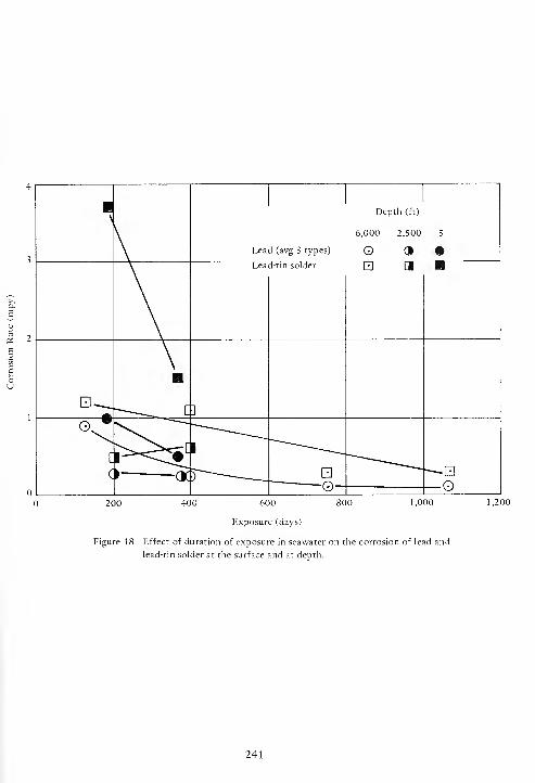
600
Exposure (days)
1,000
Figure 18. Effect of duration of exposure in seawater on the corrosion of lead and
lead-tin solder at the surface and at depth.
241
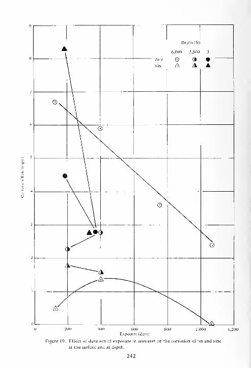
400 800 1,000600Exposure (days)
Figure 19. Effect of duration of exposure in seawater on the corrosion of tin and zinc
at the surface and at depth.
242
1,200
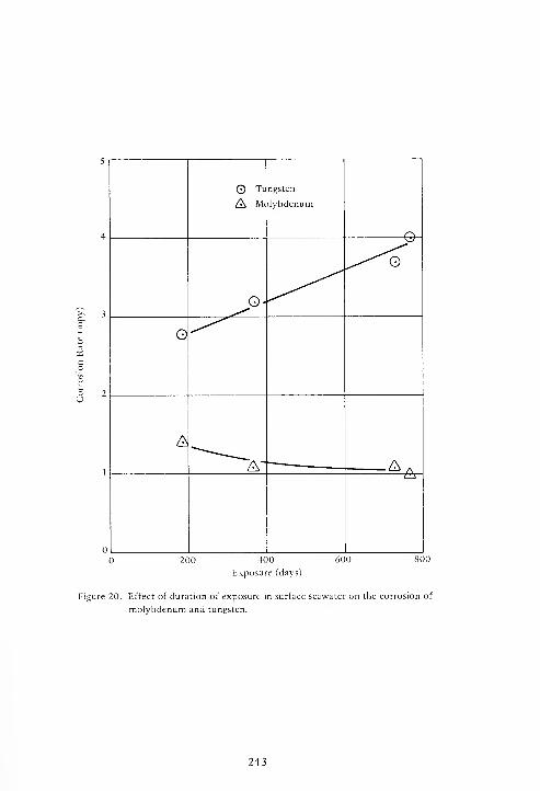
400
Exposure (days)
800
Figure 20. Effect of duration of exposure in surface seawater on the corrosion of
molybdenum and tungsten.
243

3,000
4,000
5,000
6,000
7,000
Corrosion Rate (mpy)
Figure 21. Effect of depth on the corrosion of miscellaneous alloys after 1 year
of exposure.
244
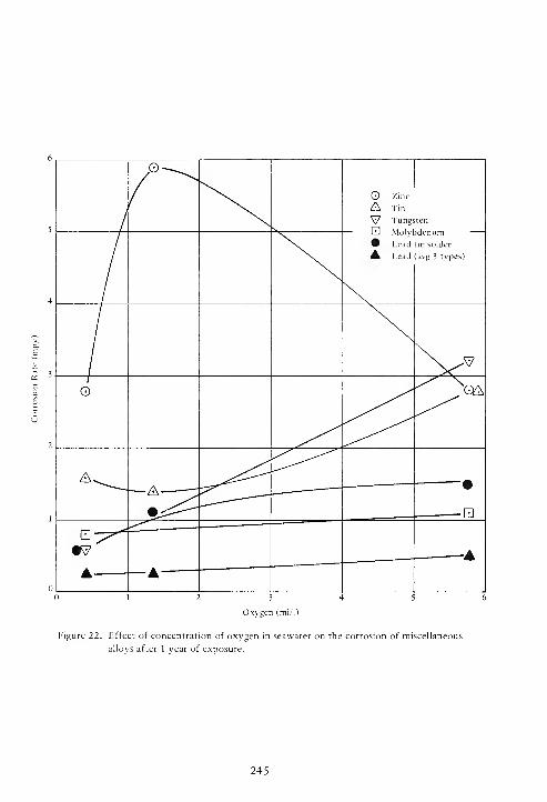
Oxygen (ml/1)
Figure 22. Effect of concentration of oxygen in seawater on the corrosion of miscellaneous
alloys after 1 year of exposure.
245
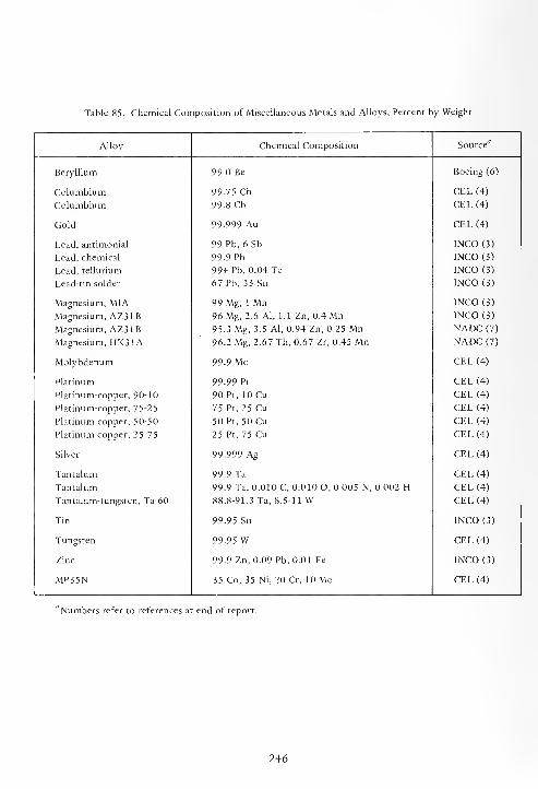
Table 85. Chemical Composition of Miscellaneous Metals and Alloys, Percent by Weight
Alloy Chemical Composition Source"
Beryllium 99.0 Be Boeing (6)
Columbium 99.75 Cb CEL(4)
Columbium 99.8 Cb CEL (4)
Gold 99.999 Au CEL (4)
Lead, antimonial 99 Pb, 6 Sb INCO (3)
Lead, chemical 99.9 Pb INCO(3)
Lead, tellurium 99+ Pb, 0.04 Te INCO (3)
Lead-tin solder 67 Pb, 33 Sn INCO (3)
Magnesium, MIA 99 Mg, 1 Mn INCO (3)
Magnesium, AZ31B 96 Mg, 2.6 Al, 1.1 Zn, 0.4 Mn INCO (3)
Magnesium, AZ31B 95.3 Mg, 3.5 Al, 0.94 Zn, 0.25 Mn NADC (7)
Magnesium, HK31A 96.2 Mg, 2.67 Th, 0.67 Zr, 0.45 Mn NADC (7)
Molybdenum 99.9 Mo CEL (4)
Platinum 99.99 Pt CEL (4)
Platinum-copper, 90-10 90 Pt, 10 Cu CEL (4)
Platinum-copper, 75-25 75 Pt, 25 Cu CEL (4)
Platinum-copper, 50-50 50 Pt, 50 Cu CEL (4)
Platinum-copper, 25-75 25 Pt, 75 Cu CEL (4)
Silver 99.999 Ag CEL (4)
Tantalum 99.9 Ta CEL (4)
Tantalum 99.9 Ta, 0.010 C, 0.010 O, 0.005 N, 0.002 H CEL (4)
Tantalum-tungsten, Ta 60 88.8-91.3 Ta, 8.5-11 W CEL (4)
Tin 99.95 Sn INCO (3)
Tungsten 99.95 W CEL (4)
Zinc 99.9 Zn, 0.09 Pb, 0.01 Fe INCO (3)
MP35N 35 Co, 35 Ni, 20 Cr, 10 Mo CEL (4)
"Numbers refer to references at end of report.
246
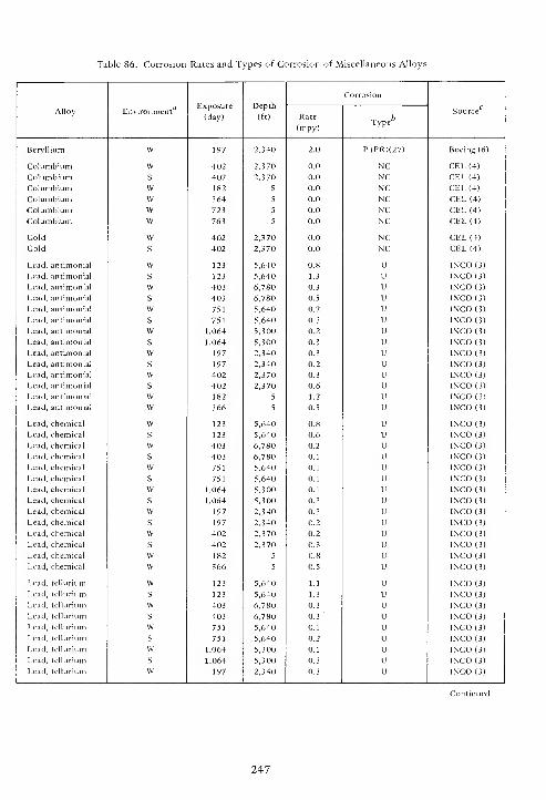
Table 86. Corrosion Rates and Types of Corrosion of Miscellaneous Alloys
Exposure
(day)
Depth
(ft)
Corrosion
Alloy Environment4
Rate
(mpy)Type
Source
Beryllium W 197 2,340 2.0 P(PR)(27) Boeing (6)
Columbium W 402 2,370 0.0 NC CEL(4)
Columbium S 402 2,370 0.0 NC CEL(4)
Columbium W 182 5 0.0 NC CEL (4)
Columbium VV 364 5 0.0 NC CEL(4)Columbium W 723 5 0.0 NC CEL (4)
Columbium W 763 5 0.0 NC CEL (4)
Gold W 402 2,370 0.0 NC CEL (4)
Gold S 402 2,370 0.0 NC CEL (4)
Lead, antimonial W 123 5,640 0.8 U INCO(3)Lead, antimonial S 123 5,640 1.3 U 1NCO (3)
Lead, antimonial W 403 6,780 0.3 u INCO(3)Lead, antimonial S 403 6,780 0.5 u INCCM3)Lead, antimonial W 751 5,640 0.2 u INCO(3)Lead, antimonial s 751 5,640 0.3 u INCO(3)
Lead, antimonial w 1,064 5,300 0.2 u lNCO(3)Lead, antimonial s 1,064 5,300 0.3 u 1NCO (3)
Lead, antimonial w 197 2,340 0.3 u INCO (3)
Lead, antimonial s 197 2,340 0.2 u INCO(3)Lead, antimonial w 402 2,370 0.3 u INCO (3)
Lead, antimonial s 402 2,370 0.6 u 1NCO (3)
Lead, antimonial w 182 5 1.2 u INCO (3)
Lead, antimonial w 366 5 0.5 u INCO (3)
Lead, chemical w 123 5,640 0.8 u INCO (3)
Lead, chemical s 123 5,640 0.6 u INCO (3)
Lead, chemical w 403 6,780 0.2 u INCO (3)
Lead, chemical s 403 6,780 0.1 u INCO (3)
Lead, chemical w 751 5,640 0.1 u INCO (3)
Lead, chemical s 751 5,640 0.1 u INCO (3)
Lead, chemical w 1,064 5,300 0.1 u INCO (3)
Lead, chemical s 1,064 5,300 0.3 u INCO (3)
Lead, chemical w 197 2,340 0.3 u INCO (3)
Lead, chemical s 197 2,340 0.2 u INCO (3)
Lead, chemical w 402 2,370 0.2 u INCO (3)
Lead, chemical s 402 2,370 0.3 u INCO (3)
Lead, chemical w 182 5 0.8 u INCO (3)
Lead, chemical w 366 5 0.5 u INCO (3)
Lead, tellurium w 123 5,640 1.1 u INCO (3)
Lead, tellurium s 123 5,640 1.3 u INCO (3)
Lead, tellurium w 403 6,780 0.3 u INCO (3)
Lead, tellurium s 403 6,780 0.3 u INCO (3)
Lead, tellurium w 751 5,640 0.1 u INCO (3)
Lead, tellurium s 751 5,640 0.2 u INCO (3)
Lead, tellurium w 1,064 5,300 0.1 u INCO (3)
Lead, tellurium s 1.064 5,300 0.3 u INCO (3)
Lead, tellurium w 197 2,340 0.3 u INCO (3)
247
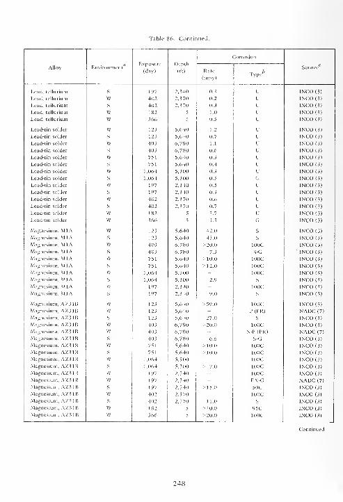
Table 86. Continued.
Exposure
(day)
Depth
(ft)
Corrosion
Alloy EnvironmentRate
(mpy)•r bType
Source
Lead, tellurium S 197 2,340 0.3 U lNCO(3)
Lead, tellurium W 402 2,370 0.2 u INCO (3)
Lead, tellurium S 402 2,3 70 0.3 u INCO (3)
Lead, tellurium W 182 5 1.0 u lNCO(3)
Lead, tellurium W 366 5 0.5 u INCO (3)
Lead-tin solder w 123 5,640 1.2 u INCO (3)
Lead-tin solder s 123 5,640 0.7 u INCO (3)
Lead-tin solder w 403 6,780 1.1 u INCO (3)
Lead-tin solder s 403 6,780 0.6 u INCO (3)
Lead-tin solder w 751 5,640 0.3 u INCO (3)
Lead-tin solder s 751 5,640 0.4 u INCO (3)
Lead-tin solder w 1,064 5,300 0.3 u INCO (3)
Lead-tin solder s 1,064 5,300 0.5 G INCO (3)
Lead-tin solder w 197 2,340 0.5 u INCO (3)
Lead-tin solder s 197 2,340 0.3 u INCO (3)
Lead-tin solder w 402 2,370 0.6 u INCO (3)
Lead-tin solder s 402 2,3 70 0.7 u INCO (3)
Lead-tin solder w 182 5 3.7 u INCO (3)
Lead-tin solder w 366 5 1.5 G INCO (3)
Magnesium, MIA w 123 5,640 42.0 s INCO (3)
Magnesium, MIA s 123 5,640 43.0 s INCO (3)
Magnesium, MIA w 403 6,780 >20.0 100C INCO (3)
Magnesium, MIA s 403 6.780 7.3 S-G INCO (3)
Magnesium, MIA vv 751 5,640 >10.0 100C INCO (3)
Magnesium, MIA s 751 5,640 >12.0 100C INCO (3)
Magnesium, MIA w 1,064 5,300 - 100C INCO (3)
Magnesium, MIA s 1,064 5,300 2.9 s INCO (3)
Magnesium, MIA vy 197 2,340 - 100C INCO (3)
Magnesium, MIA s 197 2,340 9.0 s INCO (3)
Magnesium, AZ31B vv 123 5,640 >59.0 100C INCO (3)
Magnesium, AZ31B vv 123 5,640 - P (PR) NADC (7)
Magnesium, AZ31B s 123 5,640 27.0 s INCO (3)
Magnesium, AZ31B w 403 6,780 >20.0 100C INCO (3)
Magnesium, AZ31B w 403 6,780 - N-P (PR) NADC (7)
Magnesium, AZ31B s 403 6,780 6.6 S-G INCO (3)
Magnesium, AZ31B w 751 5,640 >10.0 100C INCO (3)
Magnesium, AZ31B s 751 5,640 >10.0 100C INCO (3)
Magnesium, AZ31B vv 1,064 5,300 - 100C INCO (3)
Magnesium, AZ31B s 1,064 5,300 > 7.0 100C INCO (3)
Magnesium, AZ31B w 197 2,340 - 100C INCO (3)
Magnesium, AZ31B w 197 2,340 - EX-G NADC (7)
Magnesium, AZ31B s 197 2,340 >15.0 50C INCO (3)
Magnesium, AZ31B vv 402 2,3 70 - 100C INCO (3)
Magnesium, AZ31B s 402 2,370 11.0 S INCO (3)
Magnesium, AZ31B vv 182 5 >40.0 95C INCO (3)
Magnesium, AZ31B vv 366 5 >20.0 100C INCO (3)
248

Table 86. Continued.
Alloy- Environment'Exposure
(day)
Depth
(ft)
Corrosion
SourceRate
(mpy)„ bType
Magnesium, HK31A W 403 6,780 _ S-G'
NADC (7)
Magnesium, HK31A W 197 2,340 - EX-G rf NADC (7)
Molybdenum W 402 2,370 0.8 C(9);U CEL(4)Molybdenum S 402 2,370 0.8 C(6); U CEL(4)Molybdenum w 182 5 1.4 U CEL(4)Molybdenum vv 364 5 1.1 U-ET CEL (4)
Molybdenum w 723 5 1.1 G CEL (4)
Molybdenum w 763 5 1.0 C(6);G CEL (4)
Platinum w 402 2,370 0.0 NC CEL (4)
Platinum s 402 2,370 0.0 NC CEL (4)
90PM OCu w 402 2,370 0.0 NC CEL (4)
90Pt-10Cu s 402 2,370 0.0 NC CEL (4)
75Pt-25Cu w 402 2,370 0.0 NC CEL (4)
75Pt-25Cu s 402 2,370 0.0 NC CEL (4)
50Pt-50Cu w 402 2,370 - ET CEL (4)
5 OP t- 5OCu s 402 2,370 - ET;P CEL (4)
25Pt-75Cu w 402 2,370 - ET;P CEL (4)
25Pt-75Cu s 402 2,370 - ET;P CEL (4)
Silver w 402 2,370 0.6 U CEL (4)
Silver s 402 2,370 0.5 U CEL (4)
Tantalum w 402 2,3 70 0.0 NC CEL (4)
Tantalum s 402 2,370 0.0 NC CEL (4)
Tantalum w 182 5 0.0 NC CEL (4)
Tantalum vv 364 5 0.0 NC CEL (4)
Tantalum w 723 5 0.0 NC CEL (4)
Tantalum w 763 5 0.0 NC CEL (4)
Ta-60 w 182 5 0.0 NC CEL (4)
Ta-60 w 364 5 0.0 NC CEL (4)
Ta-60 w 723 5 0.0 NC CEL (4)
Ta-60 w 763 5 0.0 NC CEL (4)
Tin w 123 5,640 0.5 G 1NCO (3)
Tin s 123 5,640 0.6 G lNCO(3)Tin w 403 6,780 1.4 P(17) INCO (3)
Tin s 403 6,780 1.7 SH-CR INCO(3)Tin w 751 5,640 20.4 P(PR)(30) INCO (3)
Tin s 751 5,640 0.1 G INCO (3)
Tin vv 1,064 5,300 < 0.1 SC-ET INCO (3)
Tin s 1.064 5,300 0.3 G INCO (3)
Tin w 197 2,340 1.8 C(2);CR (2) INCO (3)
Tin s 197 2,340 < 0.1 P(2) INCO (3)
Tin vv 402 2,370 1.6 SC-P (9) INCO (3)
Tin s 402 2,370 0.1 CO) INCO (3)
Tin w 182 5 8.3 P(PR)(30) INCO (3)
Tin vv 366 5 2.8 C(PR)(30);P(PR)(30) INCO (3)
249
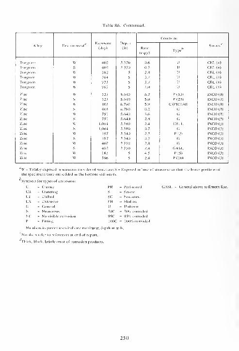
Table 86. Continued.
Corrosion
Alloy EnvironmentExposure
(day)
Depth
(ft) Rate
(mpy)„ bType
Source
Tungsten W 402 2,370 0.6 U CEL (4)
Tungsten S 402 2,370 0.5 U CEL(4)Tungsten W 182 5 2.8 u CEL (4)
Tungsten W 364 5 3.2 u CEL (4)
Tungsten W 723 5 3.7 u CEL (4)
Tungsten W 763 5 4.0 u CEL (4)
Zinc W 123 5,640 6.7 P(13) 1NCCM3)Zinc S 123 5,640 5.0 P(25) 1NCO (3)
Zinc W 403 6,780 5.9 C(PR)(30) 1NCO (3)
Zinc S 403 6,780 0.2 G INCO (3)
Zinc W 751 5,640 3.6 G INCO (3)
Zinc s 751 5,640 2.8 G INCO (3)
Zinc w 1,064 5,300 2.4 CR; E INCO (3)
Zinc s 1,064 5,300 0.7 G INCO (3)
Zinc w 197 2,340 2.3 P (2) INCO (3)
Zinc s 197 2,340 0.3 G INCO (3)
Zinc w 402 2,370 2.8 G INCO (3)
Zinc s 402 2,370 2.4 GASL INCO (3)
Zinc w 182 5 4.5 P(5) INCO (3)
Zinc w 366 5 2.8 P(10) INCO (3)
' W = Totally exposed in seawater on sides of structure ; S = Exposed in base of structure so that the lower portions of
the specimens were embedded in the bottom sediments.
Symbols for types of corrosion:
C = Crevice
CR = Cratering
ET = Etched
EX = Extensive
G = General
N = Numerous
NC = No visible corrosion
P = Pitting
Numbers in parentheses indicate maximum depth in mil
Numbers refer to references at end of report.
Thick, black, brittle crust of corrosion products.
PR = Perforated
S = Severe
sc = Scattered
SH = Shallow
U = Uniform
50C = 50% corroded
95C = 95% corroded
100C = 100% corroded
General above sediment line.
250
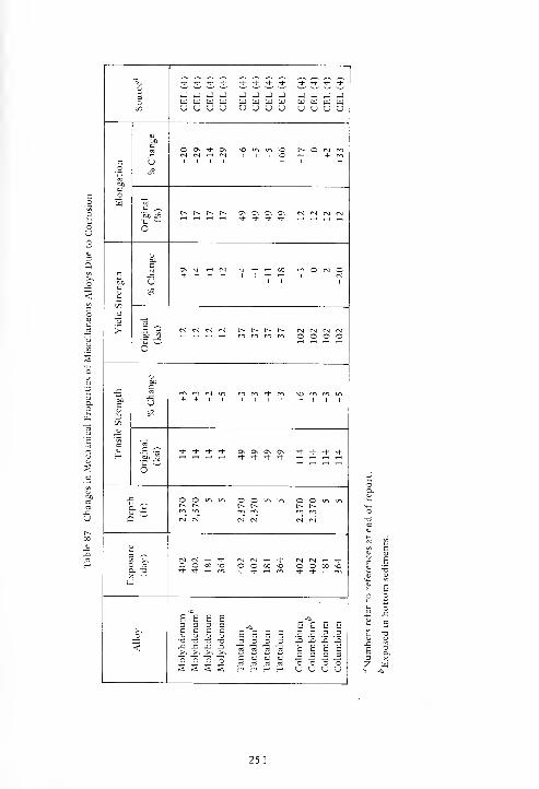
3Ot/5
CEL(4) CEL
(4)
CEL(4) CEL
(4)
CEL
(4)
CEL
(4)
CEL
(4)
CEL
(4)
CEL
(4)
CEL
(4)
CEL
(4)
CEL
(4)
CO
boc_o
s
boC
-CU
00\^}-Os vou-im^O r^Oc^rn<N CN *-i <N IIIOt-h +rn
1 1 1 1 +1 +
O
r^t^r^r-- o\ o\ o\ Os n n rs m
socu
to
60c
UOv * H N i- H H 03 r.-.OMO+ + + + l+^H^H | |(M
1 1 1
"3
6~
rs m n n r^r^r^r^ n N M N^-t t-h .—< y-t mmrrim OOOO
J3
cl)
C/)
<u
c
H
BOc
-CU
m m cm in m m Th m somrnin+ + 1 +iii
o~
,_, tH i-l iH ^. ^. ^. ^. ,_, ,_, ^ ^
Q
OOu-iu-. O O in in © O in in
m r*i rr, r^ rri m
3 <~>
O rt
Q. 73
w
N N H ^ N N H ^ <N CM .-< <*O O 00 ^ OO00M3 OOOO^O+ + .-H m + t H tfi ^(-^j-^Hr^
<Molybdenum Molybdenum Molybdenum Molybdenum
Tantalum Tantalum Tantalum Tantalum
Columbium Columbium Columbium Columbium
251

SECTION 9
WIRE ROPES
Wire ropes of many different chemical composi-
tions, with different types of coatings, of different
sizes, and of different types of construction were
exposed in seawater at depth to determine their
corrosion behavior. Some were stressed in tension to
determine their susceptibility to stress corrosion or
whether stress increased their rates of corrosion.
The chemical compositions of the ropes are given
in Table 88, and their corrosion behavior in Table 89.
There was no visible corrosion on rope numbers
15, 18, 19, 20, 21, 22, 41 (751 days, 6,000 feet), 48,
49, 50, 51, 52, and 53. Rope number 15 was Type
316 stainless steel modified by adding silicon and
nitrogen and was exposed for 189 days at the
6,000-foot depth. Wire rope number 41, conventional
Type 316, was uncorroded after 751 days of expo-
sure at the 6,000-foot depth, but was rusted with
some internal wires broken and crevice corrosion
after 1,064 days of exposure; its breaking strength
was decreased by 41% after 1,064 days of exposure at
the 6,000-foot depth. Because the conventional Type
316 stainless steel was not corroded until between
751 and 1,064 days of exposure, it cannot be stated
that the addition of silicon and nitrogen to the Type
316 stainless steel improved its corrosion resistance.
Rope numbers 18, 19, 20, and 21 were nickel
base alloys. Rope numbers 20 and 21 were also
uncorroded when lying on or in the bottom sediment.
Rope number 22 was a cobalt base alloy which
was also uncorroded when lying on or in the bottom
sediment. It, also, was not susceptible to stress cor-
rosion in either the seawater or the bottom sediment
when stressed to 40% of its breaking strength.
Rope numbers 48, 49, 50, 51, 52, and 53 were
6A1-4V-Ti ropes and wires. The ropes and wires them-
selves were not corroded, but the Type 304 stainless
steel fittings and steel tie wires were severely
corroded galvanically.
All the other wire ropes, coated or uncoated,
were corroded to varying degrees of severity, the
most severe being the parting of the wires.
Bare steel wires 1, 2, 3, 35, and 36, as expected,
were completely covered with rust. There was no loss
of strength after periods of exposure of as long as
1,064 days. These ropes had been lubricated during
fabrication; the lubricant on the outer surfaces of the
ropes had disappeared, but not on the internal
surfaces during exposure. One rope, No. 2, was
degreased prior to exposure; as a result, it was more
severely corroded than the others on the outside sur-
faces, and there was light rust on many of the internal
"^SRx9. One rope, No. 3, was degreased, then wrapped
with 10-mil-thick polyethylene tape prior to expo-
sure. There was heavy rust underneath the tape for a
distance of about 3 feet from each end and there was
light rust on about 75% of the internal wires. Wires
35 and 36 had been stressed in tension to 20% of
their respective breaking strengths prior to exposure.
These two ropes were covered with rust with no rust
on the internal wires, did not fail by stress corrosion,
and had no decrease in'their breaking strengths.
The galvanized (zinc-coated) ropes were numbers
4, 5, 6, 23, 24, 25, 26, 27, 28, 37, and 38. The zinc
coatings protected the steel wires, but there was no
good correlation between the weight or thickness of
coating and the duration of protection. In general,
except for the electrogalvanized coating, the heavier
the coating the longer the period of time before rust
appeared on the ropes. The breaking strengths of the
ropes were not impaired by exposures for as long as
1,064 days of exposure. Also, rope numbers 37 and
38 were not susceptible to stress corrosion when
stressed to 20% of their respective breaking strengths.
Rope numbers 7, 8, 9, and 40, in addition to
being galvanized, were also jacketed with plastic
coatings. In all cases, seawater penetrated along the
interfaces between the ropes and the jackets. There
was some light rust on the strands of rope number 40
underneath the poly (vinyl chloride) jacket after 751
days of exposure. The polyurethane (rope number 7)
and polyethylene (rope numbers 8 and 9) jackets
protected the galvanized ropes to a considerable
extent. The jackets were not punctured or broken,
but seawater had penetrated to the metal ropes
through the end terminations. That water had pene-
trated to the interface between the jackets and the
ropes was proven by puncturing the jackets, at which
time seawater spurted out under considerable
253
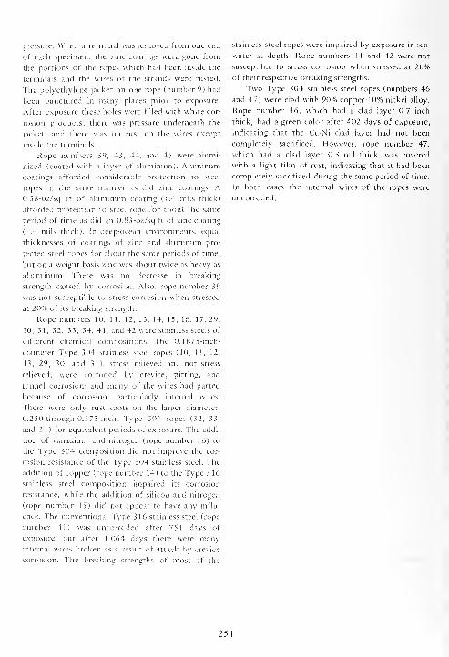
pressure. When a terminal was removed from one end
of each specimen, the zinc coatings were gone from
the portions of the ropes which had been inside the
terminals and the wires of the strands were rusted.
The polyethylene jacket on one rope (number 9) had
been punctured in many places prior to exposure.
After exposure these holes were filled with white cor-
rosion products; there was pressure underneath the
jacket; and there was no rust on the wires except
inside the terminals.
Rope numbers 39, 43, 44, and 45 were alumi-
nized (coated with a layer of aluminum). Aluminum
coatings afforded considerable protection to steel
ropes in the same manner as did zinc coatings. A0.38-oz/sq ft of aluminum coating (1.4 mils thick)
afforded protection to steel rope for about the same
period of time as did an 0.83-oz/sq ft of zinc coating
(1.4 mils thick). In deep-ocean environments, equal
thicknesses of coatings of zinc and aluminum pro-
tected steel ropes for about the same periods of time,
but on a weight basis zinc was about twice as heavy as
aluminum. There was no decrease in breaking
strength caused by corrosion. Also, rope number 39
was not susceptible to stress corrosion when stressed
at 20% of its breaking strength.
Rope numbers 10, 11, 12, 13, 14, 15, 16, 17, 29,
30, 31, 32, 33, 34, 41, and 42 were stainless steels of
different chemical compositions. The 0.1875-inch-
diameter Type 304 stainless steel ropes (10, 11, 12,
13, 29, 30, and 31), stress relieved and not stress
relieved, were corroded by crevice, pitting, and
tunnel corrosion; and many of the wires had parted
because of corrosion, particularly internal wires.
There were only rust spots on the larger diameter,
O.250-through-0.375-inch, Type 304 ropes (32, 33,
and 34) for equivalent periods of exposure. The addi-
tion of vanadium and nitrogen (rope number 16) to
the Type 304 composition did not improve the cor-
rosion resistance of the Type 304 stainless steel. The
addition of copper (rope number 14) to the Type 3 16
stainless steel composition impaired its corrosion
resistance, while the addition of silicon and nitrogen
(rope number 15) did not appear to have any influ-
ence. The conventional Type 316 stainless steel (rope
number 41) was uncorroded after 751 days of
exposure, but after 1,064 days there were manyinternal wires broken as a result of attack by crevice
corrosion. The breaking strengths of most of the
stainless steel ropes were impaired by exposure in sea-
water at depth. Rope numbers 41 and 42 were not
susceptible to stress corrosion when stressed at 20%of their respective breaking strengths.
Two Type 304 stainless steel ropes (numbers 46
and 47) were clad with 90% copper-10% nickel alloy.
Rope number 46, which had a clad layer 0.7 inch
thick, had a green color after 402 days of exposure,
indicating that the Cu-Ni clad layer had not been
completely sacrificed. However, rope number 47,
which had a clad layer 0.3 mil thick, was covered
with a light film of rust, indicating that it had been
completely sacrificed during the same period of time.
In both cases the internal wires of the ropes were
uncorroded.
254
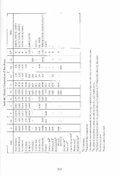
rt
u
oo
> > No rg > X
V
V
N
qV
£*
o
Od
Z > J3 <f£ 2 U * X z
*uw " "
5'f OS as as OS ^ 1 1
rriaS as as as 1
—
vO
-1
!n *
o o oi i 1
O1 1 1 1 1
oV V
^ ^ ,_, N „.
S 0\ t^1 1 1 1
V
r-l ift^ 00 ON o o o X * o o o
X CO ON in o X c\ X ON t^ CN
3 o _ M VO ^t^ X ON o o o
in m m t^ o in c^ tH Tj- o o (NI o 3" rt ~* "" vu m - - ^ "* 'H rf ""*
OS 00 00 fS m - ^ t^
C/3 - N d - 31
3 d d1 1 1
m in _ x X r^ 1NT>
3 O -"• "d
od
o iti ni in o ,_,
oo
Oo o
OO
oo
1 1 od
1 1 1 1
m o in _ inc
1/1 rj n en ^ _X X X
o O o o o o o 1
o o o"
V/ -n
n
12
C/3
2U
2>2
y
2
y
yy6S2
y6y2
o
o
y2
y2
2
y
2
1U
-to
o->,
So
<
\o
D.
<
TO
G
ouo
U
Aircraft
cable
6
Plow
steel
Improved
plov
o
<<5
E
c c c
I 1 1
- - - S £
2 Z 2 2
255

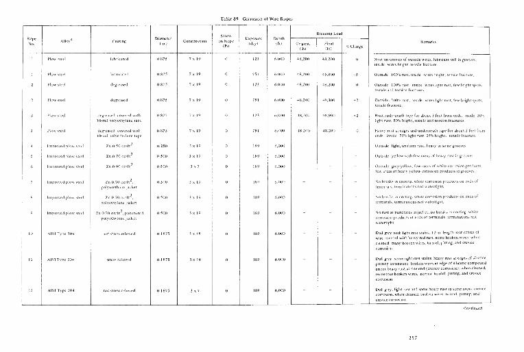
Table 89. Corrosion of Wire Ropes
Rope
No...o/ Coating
Diameter
(in.)Construction
Stress
on Rope
(lb)
Exposure
(day)
Depth
(ft)
Breaking Load
Remarks
(lb)
Final
(lb)% Change
1 Plow steel lubricated 0.875 7x 19 123 6,000 48,200 48,200 Rust on crowns of outside wires; lubricant still in grooves-,
inside: wires bright; tensile fracture.
1 Plow steel lubricated 0.875 7x 19 751 6,000 48,200 45,800 -5 Outside; 100% rust; inside: wires bright; tensile fracture.
2 Plow steel degreased 0.875 7x 19 123 6,000 48,200 48,200 Outside: 100% rust; inside; wires light rust, few bright spots;
tensile and torsion fractures.
2 Plow steel degreascd 0.875 7x 19 751 6,000 48,200 49.300 +2 Outside: 100% rust; inside; wires light rust, few bright spots,
tensile fracture.
3 Plow steel degreased; covered with
10-mil polyethylene tape
0.875 7x 19 123 6.000 48.200 48,900 + 2 Rust underneath tape for about 3 feet from ends; inside: 50%light rust, 50% bright; tensile and torsion fractures.
3 Plow steel degreased; covered with
10-mil polyethylene tape
0.875 7x 19 751 6,000 48,200 48,200 Heavy rust at edges and underneath tape for about 3 feet from
ends, inside; 75% light rust, 25% bright; tensile fracture.
4 Improved plow steel Zn 0.50 oz/ft2
0.250 3 x 19 189 6,000 " - - Outside light, uniform rust, heavy in some grooves.
5 Improved plow steel Zn 0.70 oz/ft2 0.500 3x 19 189 6,000 - - " Outside: yellow with few areas of heavy rust in grooves.
6 Improved plow steel Zn 0.90 oz/ft2 0.500 3 x 7 189 6,000 - - " Outside: grey-yellow, few areas of white corrosion products,
few areas of heavy yellow corrosion products in grooves.
7 Improved plow steel Zn 0.70 oz/ft2
,
polyurethane jacket
0.500 3 x 19 189 6,000 " " - No breaks in coating, white corrosion products on ends of
terminals; terminations not watertight.
8 Improved plow steel Zn 0.70 oz/ft2
.
polyethylene jacket
0.500 3 x 19 189 6,000 " " - No breaks in coating; white corrosion products on ends of
terminals; terminations not watertight.
9 Improved plow steel Zn 0.70 oz/ft2
,punctured
polyethylene jacket
0.500 3x 19 189 6,000 ~ No rust at punctures in jacket; no breaks in coating; white
corrosion products at ends of terminals; terminations not
watertight.
10 A1SI Type 304 not stress relieved 0.1875 3x 19 189 6,000 Dull grey with light rust stains; 1 2-in. length near center of
wire covered with heavy red rust; some broken wires; when
cleaned, many broken wires, tunnel, pitting, and crevice
11 AISIType 304 stress relieved 0.1875 3 x 19 189 6,000 " " ~ Dull grey; some light rust stains; heavy rust at edges of silicone
potting compound; broken wires at edge of silicone compound
under heavy rust at one end (crevice corrosion); when cleaned,
numerous broken wires, internal tunnel, pitting, and crevice
12 A1S1 Type 304 not stress relieved 0.1875 3 x7 189 6,000 - - ~ Dull grey; light rust and some heavy rust in some areas; crevice
corrosion; when cleaned, broken wires, tunnel, pitting, and
257

Table 89. Continued.
Rope
No.Alloy" Coating
Diameter
(in.)Construction
Stress
(lb)
Exposure
(day)
Depth
(ft)
Breaking Load
RemarksOriginal
(lb)
Final
(lb)% Change
13 AIS1 Type 304 stress relieved 0.1875 3 x 7 189 6,000 - - " Dull grey; light rust stains; few pits on crowns of outside wires;
when cleaned, crevice, pitting, and tunnel corrosion.
14 Fe-Cr-Ni-Mo-Cu bare 0.125 3x7 189 6,000 " " " Dull grey with mottled light yellow stains; when cleaned,
incipient crevice corrosion.
15 Fe-Cr-Ni-Mo-Si-N bare 0.125 1 X 7 189 6,000 " " " No visible corrosion; metallic sheen still present.
16 Fe-Cr-Ni-V-N bare 0.125 1 x7 189 6,000 - - " Failed by tunnel and crevice corrosion underneath silicone
potting compound; only end loops recovered.
17 Fe-Cr-Ni-Si bare 0.125 1 X 7 189 6,000 - " " Grey, no visible corrosion; when cleaned, many areas of slight
crevice corrosion and shallow pitting.
18 Ni-Co-Cr-Mo bare 0.0625 1 X 7 189 6,000 " - - No visible corrosion, original metallic sheen intact.
19 Ni-Mo-Cr C bare 0.0625 1 x 7 189 6,000 - " " No visible corrosion; original metallic sheen intact.
20 Ni-Cr-Mo625 bare 0.250 7x 19 189 6,000 7,400 " " No visible corrosion; original metallic sheen intact.
, 20 Ni-Cr-Mo 62 56
bare 0.250 7x 19 189 6,000 7.400 " " No visible corrosion; original metallic sheen intact.
21 Ni-Cr-Mo 103 bare 0.250 7x 19 189 6,000 7.000 " " No visible corrosion; original metallic sheen intact.
21 Ni-Cr-Mo \0ib
bare 0.250 7x 19 189 6,000 7,000 " - No visible corrosion; original metallic sheen intact.
22 Co-Cr-Ni-Fe-Mo bare 0.1875 3x 19 189 6,000 4.000 - " Original blue film gone; no visible corrosion.
22 Co-Cr-Ni-Fe-Mo bare 0.1875 3x 19 1,600 189 6.000 4,000 " - No wire failures; original blue film gone; no visible corrosion.
22 Co-Cr-Ni-Fe-Mo'' bare 0.1875 3x 19 189 6,000 4,000 " " Original blue film gone; no visible corrosion.
22 Co-Cr-Ni-Fe-Mo'' bare 0.1875 3x 19 1,600 189 6.000 4,000 - - No wire failures; original blue film gone; no visible corrosion.
23 Aircraft cord Zn 0.40 oz/ft2
0.0938 7x7 403 6,000 1,100 1,100 Dark grey to black; tensile fracture.
23 Aircraft cord Zn 0.40 oz/ft2
0.0938 7x7 197 2,500 1,100 l.ooo -9 Outside: 100% rust; inside: grey; tensile fracture.
24 Aircraft cable Zn 0.40 oz/ft2
0.125 7 x 19 403 6,000 2,000 1,000 -50 Dark grey to black; inside: grey; tensile fracture.
24 Aircraft cable Zn 0.40 oz/ft2
0.125 7x 19 197 2,500 2,000 1,800 -10 Outside: 100% rust; inside; grey; tensile and torsion fractures.
25 Aircraft cable Zn 0.50 oz/ft2
0.1875 7x 19 403 6,000 3,500 4,000 + 14 Outside; dark grey to black; inside: grey; tensile and torsion
25 Aircraft cable Zn 0.50 oz/ft2
0.1875 7x 19 197 2,500 3.500 3,700 +6 Outside: dark grey; inside: grey; tensile and torsion fractures.
26 Wire rope Zn 0.50 oz/ft2
0.1875 1 x7 403 6,000 2.600 2,600 Outside: 90% rust; inside: grey; tensile fracture.
26 Wire rope Zn 0.50 oz/ft2
0.1875 1 X 7 197 2,500 2,600 2,500 -4 Outside: medium grey, few rust spots; inside: grey; tensile

Table 89. Continued.
Rope
No.Alloy" Coating
Diameter
(in.)Construction
Stress
on Rope
(lb)(day)
Depth
(ft)
ireaking Loa 1
Remarks
(lb)
Final
(lb)% Change
27 Wire rope Zn 0.85 oz/ft2
0.250 1 X 7 403 6.000 5,900 4,600 -22 Outside: 100% yellow; inside: grey; tensile fracture.
27 Wire rope Zn 0.85 oz/ft2
0.250 1 x 7 197 2.500 5.900 5,300 -10 Outside: medium grey, few rust spots; inside, grey; tensile
28 Aircraft cable Zn 0.60 oz/ft2
0.250 7x 19 403 6,000 6,100 5,900 -2 Outside: dark grey to black; inside: grey; tensile and
28 Aircraft cable Zn 0.60 oz/ft2
0.250 7x 19 197 2.500 6.100 6,200 +2 Outside: dark grey to black; inside: grey; tensile fracture.
29 Aircraft cord bare, Type 304 0.0938 7x7 403 6,000 800 100 -88 Internal strands corroded, tunnel, crevice, and pitting; manywires parted by corrosion.
29 Aircraft cord bare, Type 304 0.0938 7x7 197 2,500 800 800 Outside: few rust spots; inside: bright; tensile fracture.
30 Aircraft cable bare, Type 304 0.125 7x 19 403 6,000 1,600 200 -88 Outside: few rust stains; inside: broken wires, crevice and
pitting corrosion.
30 Aircraft cable bare, Type 304 0.125 7x 19 197 2,500 1,600 1,800 + 13 Outside: original metallic lustre; inside: bright; tensile fracture.
31 Aircraft cable bare. Type 304 0.1875 7x 19 403 6,000 2,700 100 -96 Outside: many rust stains and broken wires, pitting, tunnel and
crevice corrosion; inside; many broken wires, pitting, tunnel,
31 Aircraft cable bare, Type 304 0.1875 7x 19 197 2,500 2,700 2,800 4 Outside: few rust spots; inside: bright; tensile fracture.
32 Aircraft cable bare, Type 304 0.250 7x 19 403 6,000 5,100 5,000 -2 Outside; few yellow stains; inside: bright; tensile fracture.
32 Aircraft cable bare, Type 304 0.250 7x 19 197 2.500 5,100 5,100 Outside: original metallic sheen; inside: bright; tensile and
33 Aircraft cable bare, Type 304 0.3125 7x 19 403 6,000 7,100 7.700 +8 Outside: few rust stains, inside: bright; tensile and torsion
fractures.
33 Aircraft cable bare, Type 304 0.3125 7x 19 197 2.500 7,100 7,000 -1 Outside: original metallic lustre; inside, bright; tensile fracture.
34 Aircraft cable bare, Type 304 0.375 7x 19 403 6,000 11,900 11,700 -2 Outside: few rust stains; inside: bright; tensile and torsion
34 Aircraft cable bare. Type 304 0.375 7 x 19 197 2,500 11.900 11,600 -3 Outside; few rust stains; inside: bright; tensile fractute.
35 Plow steel lubricated 0.325 1 x 19 2,100 751 6,000 10,700 10,700 No stress failure; outside: 100% rust; inside: bright; tensile
35 Plow steel lubniued 0.325 1 x 19 2.100 1.064 6,000 10,700 11,500 +7 No stress failure; outside: 100% rust; inside: bright; tensile
fracture.
36 Improved plow steel lubricate** 0.326 1 x 19 2,900 751 6.000 14,300 14,900 +4 No stress failure; outside: 100% rust; inside: bright; tensile

Table 89. Continued.
Rope
No.Alloy" «=— Diameter
<in.)Construction
Stress
on Rope
(lb)(day)
Depth
(ft)
Breaking Load
RemarksOriginal
(lb) (lb)% Change
36 Improved plow steel lubricated 0.326 1 x 19 2,900 1,064 6,000 14,300 15,300 7 No stress failure; outside: 100% rust; inside: bright; tensile
37 Plow steel Zn 0.83 oz/ft2 0.340 1 x 19 2.100 751 6,000 10,400 10,900 + 5 No stress failure; outside: grey with 5% scattered rust;
inside: grey; tensile fracture.
37 Plow steel Zn 0.83 oz/ft2
0.340 1 x 19 2,100 1,064 6,000 10,400 8.600 -17 No stress failure; outside: 20% rust. 80% yellow; inside: grey;
tensile fracture.
38 Plow steel Zn 1.50 oz/ft2
,
electrogalvanizcd
0.335 1 x 19 2,200 751 6,000 10,900 11,100 + 2 No stress failure; outside: 50% rust. 50% grey; inside: grey;
tensile fracture.
38 Plow steel Zn 1.50 oz/ft2
,
clectrogalvanized
0.335 1 x 19 2,200 1,064 6,000 10,900 11,600 +6 No stress failure; outside: 95% rust; inside: grey; tensile
39 Plow steel Al 0.38 oz/ft2
0.335 1 x 7 1,400 751 6.000 6.900 7.000 + 1 No stress failure; outside: white corrosion producrs with 10%
rusr stains; inside: gtey; tensile fracture.
39 Plow steel Al 0.38 oz/ft2
0.335 1 x7 1,400 1,064 6,000 6.900 6,500 . -6 No stress failure; outside: white corrosion products plus 50%
rust; inside: grey and light rust, tensile fracture.
40 Plow steel Zn 0.17 oz/ft2
.
polyvinyl chloride jacket
0.195 7x7 250 751 6,000 1,300 1,200 -8 No stress failure; PVC. dull; some light rust on strands under-
neath PVC; rensile fracture.
40 Plow steel Zn0.17oz/fr2.
polyvinyl chloride jacket
0.195 7x7 250 1.064 6,000 1,300 1,100 -15 No stress failure; PVC. dull; some light rust on strands under-
neath PVC; tensile and torsion fractures.
41 Aitcraft cable bare, Type 316. lubricated 0.135 7x7 3 50 751 6.000 1,700 1,400 -18 No stress failure; outside: original metallic lustre inside
bright; tensile fractute.
41 Aircraft cable bare, Type 316. lubricated 0.135 7x7 350 1.064 6,000 1.700 1,000 -41 No sttess failure; outside: 50% rust, crevice corrosion; inside:
rusted wires, some broken, crevice corrosion, tensile and
btittle fractures.
42 Aircraft cable bare, 18O14Mn-0.5N 0.395 7x 19 2,500 751 6,000 12,400 11,400 -8 No sttess failures, outside: few rust spots, inside, brighr;
42 Aircraft cable bare. 18Cr-14Mn-0.5N 0.395 7x 19 2,500 1,064 6,000 12.400 12.500 + 1 No stress failure, ourside: considerable rust and broken wires;
inside: some broken wires in all strands; torsion fracture.
43 Improved plow stee! AI0.11 oz/ft2
0.1875 7x7 402 2,500 3.900 3.500 -10 Outside: white corrosion products with light rust stains.
44 Improved plow steel Al 0.19 oz/ft2
0.250 1 X 19 402 2.500 8,800 7,800 -11 Outside: mottled white and grey
45 Improved plow steel Al 0.19 oz/ft2
0.3125 1 X 19 402 2.500 14.000 13,000 -7 Outside: grey with some white corrosion products.
46 Type 304 9OCu-10Ni, 0.0007 in.,
0.50 oz/ft 20.1875 7x7 402 2.500 3,900 Outside: green.

Table 89. Continued.
Rope
No.Alloy" °— Diameter
<in.)Construction on Rope
(lb)
Exposure
(day)
Depth
(ft)
Breaking Load
RemarksOriginal
(lb)
Final
(lb)% Change
47
48
49
50
51
52
53
Type 304
6AI-4V-T1
6AI-4V-Ti
6A1-4V-Ti
6AI-4V-Ti
6AI-4V-Ti
6A1-4V-Ti
90Cu-10Ni, 0.0003 in.,
0.25 oz/ft2
bare, Type 304 fittings
steel tie wire
bare
0.280
0.250
0.0625
0.0625
0.063
0.045
0.020
37x7
6x 19
1 x 19
6x 19
402
402
402
402
402
402
402
2,500
2,500
2,500
2,500
2.500
2.500
2.500
- " "
Outside^ light film rust; inside: bright, uncorroded.
F ittings rusted, crevice and galvanic corrosion , cable, no
No corrosion except one steel wire which had become
introduced during fabrication.
Steel fitting and steel tie wire corroded galvanically; cable, no
No corrosion.
No corrosion.
No corrosion.
Immersed in seawater unless otherwise specified.
Immersed in bottom sediment.


SECTION 10
REFERENCES
1. U. S. Naval Civil Engineering Laboratory.
Technical Note N-657-. Environment of the Deep
Ocean Test Sites (Nominal Depth 6,000 Feet) Lati-
tude 3 3°46'N, Longitude 120°3 7'W, by K. O. Gray.
Port Hueneme, CA, Feb 1965.
2 Unpublished Oceanographic Data Reports,
11..
by K. O. Gray. Port Hueneme, CA.
3. International Nickel Co., Inc., Francis L. LaQue
Corrosion Laboratory. Reports Nos. HIP 4287.1
through HIP 4287.8. Wrightsville Beach, NC.
4. U. S. Naval Civil Engineering Laboratory. Tech-
nical Report R-504: Corrosion of materials in hydro-
space, by F. M. Reinhart. Port Hueneme, CA, Dec
1966.
5 Technical Note N-859; Corrosion rate
of selected alloys in the deep ocean, by J. B.
Crilly and W. S. Haynes. Port Hueneme, CA, Nov
1966.
6 Technical Note N-900: Corrosion of
materials in hydrospace — Part I. Irons, steels, cast
irons, and steel products, by Fred M. Reinhart. Port
Hueneme, CA, Jul 1967.
7 Technical Note N-915: Corrosion of
materials in hydrospace - Part II — Nickel and nickel
alloys, by Fred M. Reinhart. Port Hueneme, CA, Aug
1967.
8. Technical Note N-921: Corrosion of
materials in hydrospace — Part III -- Titanium and
titanium alloys, by Fred M. Reinhart. Port Hueneme,
CA, Sep 1967.
9 Technical Note N-961: Corrosion of
materials in hydrospace - Part IV - Copper and
copper alloys, by Fred M. Reinhart. Port Hueneme,
CA, Apr 1968.
10 Technical Note N-1008: Corrosion of
materials in hydrospace -- Part V — Aluminum alloys,
by Fred M. Reinhart. Port Hueneme, CA, Jan 1969.
.. Technical Note N-1023: Corrosion ' of
materials in surface sea water after 6 months of expo-
sure, by Fred M. Reinhart. Port Hueneme, CA, Mar
1969.
12.. _. Technical Note N-1172: Corrosion of
materials in hydrospace - Part VI - Stainless steels,
by Fred M. Reinhart. Port Hueneme, CA, Sep 1971.
13 .. Technical Note N-1213: Corrosion of
materials in surface seawater after 12 and 18 months
of exposure, by Fred M. Reinhart and James F.
Jenkins. Port Hueneme, CA, Jan 1972.
14 Technical Note N-1224: Corrosion of
alloys in hydrospace 189 days at 5,900 feet, by
Fred M. Reinhart and James F. Jenkins. Port Hue-
neme, CA, Apr 1972.
15. U. S. Navy Marine Engineering Laboratory.
Assignment 86-116, MEL R&D Phase Report 429/66:
Metal corrosion in deep-ocean environments, by W. L.
Wheatfall. Annapolis, MD, Jan 1967.
16. Boeing Co. Report No. D2-125376-1: Results of
197-day exposure to deep-ocean environment on
structural materials and coatings, by A. H. McClure.
Seattle, WA, 27 Mar 1967.
17. Naval Air Development Center. Aero Materials
Department Reports No. NAEC-AML-2132, NADC-MA-6868, NADC-MA-6946, NADC-MA-7048, by J. J.
DeLuccia. Johnsville, Warminster, PA, 22 Jun 1965
through 6 Oct 1970.
18. United States Steel Corporation Applied
Research Laboratory. Technical Report Project No.
39.001-100(3), Nobs-94535(FBM), SF 020-01-01,
Task 854 B-63502; Corrosion of 12Ni-5Cr-3Mo
Maraging Steel Weldments, by A. W. Loginow.
Monroeville, PA, 15 Jul 1967.
19. Shell Development Co. Corrosion of high strength
alloys in 2370 feet of seawater off Port Hueneme, by
A. K. Dunlop and G. H. Lemmer. Emergyville, CA,
13 Dec 1966.
263

20. A. C. Redfield. "Characteristics of Seawater,"
Corrosion Handbook, edited by H. H. Uhlig. NewYork, NY, John Wiley and Sons, 1948, p 1111.
21. F. L. LaQue. "Behavior of Metals and Alloys in
Seawater," Corrosion Handbook, edited by H. H.
Uhlig. New York, NY, John Wiley and Sons, 1948, p390.
22. C. P. Larrabee. "Corrosion Resistance of High-
Strength-Low-Alloy Steel as Influenced by Composi-
tion and Environment," Corrosion, vol 9, no. 8, Aug1953, pp 259-271.
23. Bell Telephone Laboratories, Inc. "The Effect of
Deep Ocean Environment on Materials," Case
38796-37, 3 Nov 1965, L. E. Fiorito, 15 Dec 1966, J.
P. McCann.
264

DISTRIBUTION LIST
SNDL No. of Total
Code Activities Copies
-1 12
FKAIC 1 10
FKNI 6 6
FKN5 9 9
FA25 1 1
_ 6 6
Defense Documentation Center
Naval Facilities Engineering Command
NAVFAC Engineering Field Divisions
Public Works Centers
Public Works Center
RDT&E Liaison Officers at NAVFAC Engineering Field
Divisions
39 39 CEL Special Distribution List for persons and activities
interested in reports on Deterioration Control
265


/

/'
i)


![Sampson Technical College [1986-1987] - Archive](https://img.pdfslide.us/doc/110x75/622b5143e731790ff226485a/sampson-technical-college-1986-1987-archive.jpg)