Embed Size (px)
Citation preview
Installation and Operation Manual
R SERIES
communitypro.com
Model
R.35-3896-EN

Page 2 Installation and Operation Manual R.35-3896-EN
IMPORTANT SAFETY INSTRUCTIONS Always follow these basic safety precautions when using or installing R SERIES loudspeakers and accessories:
• Read these instructions prior to assembly.
• Keep these instructions for reference.
• Heed all warnings.
• Follow all instructions, particularly those pertaining to rigging, mounting, hanging and electrical connections.
• Install in accordance with the manufacturer’s instruction.
• Only use attachments and accessories that are specified and approved by the manufacturer.
Refer all servicing to qualified service personnel. Servicing is required when the apparatus has been damaged in any way, does not operate normally, or has been dropped.
The terms CAUTION, WARNING, and DANGER may be used in this manual to alert the reader to important safety considerations. If you have any questions or do not understand the meaning of these terms, do not proceed with installation. Contact your local dealer, distributor, or call Community directly for assistance. These terms are defined as:
CAUTION: describes an operating condition or user action that may expose the equipment or user to potential damage or danger.
WARNING: describes an operating condition or user action that will likely cause damage to the equipment or injury to the user or to others in the vicinity.
DANGER: describes an operating condition or user action that will immediately damage the equipment and/or be extremely dangerous or life threatening to the user or to others in the vicinity.
These installation instructions are for use by qualified personnel only. To reduce the risk of fire or electric shock do not perform any servicing other than that contained in the operating instructions unless you are qualified to do so.
RIGGING AND ELECTRICAL SAFETY IMPORTANT: The loudspeakers described in this manual are designed and intended to be mounted to differing building surfaces using a variety of rigging hardware, means and methods. Installation of loudspeakers should only be performed by trained and qualified personnel. All electrical connections must conform to applicable city, county, state, and national (NEC) electrical codes.
DANGER: R SERIES rigging fittings are rated at a Working Load Limit of 100 lbs (45.4 kg) with a 10:1 safety margin. No single rigging fitting should ever be subjected to a load that is greater than 100 lbs. Failure to heed this warning could result in injury or death!
. DANGER: It is possible to experience severe electrical shock from a power amplifier. Always make sure that all power amplifiers are in the “OFF” position and unplugged from an AC Mains supply before performing electrical work.
IMPORTANT: Refer to the sections on installation and connections later in this manual for additional information on rigging and electrical safety.
CAUTION: Installation of R SERIES loudspeakers should only be performed by trained and qualified personnel. It is strongly recommended that a licensed and certified professional structural engineer approve the
mounting. Severe injury and/or loss of life may occur if this product is improperly installed.
DANGER: It is essential that a safety cable (not supplied) be utilized whenever an R SERIES Loudspeaker is installed. The safety cable must be secured to a suitable load-bearing point separate from the loudspeaker mounting point,
with as little slack as possible so as not to develop undue kinetic force if the mounting bracket (yoke) were to fail. The safety cable should be attached to the integrated SS loop on the rear of the cabinet. Refer to the Product Features images.
UNPACKING / INSPECTION R SERIES loudspeakers are engineered and manufactured to be rugged and they are carefully packed in sturdy cartons. Ensure that the number of cartons shown on the freight documents have actually been delivered. It is recommended to thoroughly inspect each unit after it has been removed from the packaging, as damage could occur during shipping.
Please note that once the shipment has left your dealer or the Community factory, the responsibility for damage is always borne by the freight company. If damage has occurred during shipping, you must file a claim directly with the freight company. It’s very important to contact the freight company as soon as possible after receiving your shipment, as most freight companies have a short time limit within which they will investigate claims. Be sure to save the carton and the packing material, as most claims will be denied if these materials are not retained. Your Community dealer and the factory will try to help in any way they can, but it is the responsibility of the party receiving the shipment to file the damage claim.
It is always a good idea to retain the carton and packing materials, if possible, in the event that the unit may need to be returned to your dealer or distributor for repair in the future.
IN THE CARTONEach shipping carton contains the following:
• One (1) R SERIES Loudspeaker
• One (1) Steel Mounting Yoke
• One (1) Weather Cover and Gasket
• Weather Cover Mounting Hardware: Pan Head Screws: 3.5 x 19mm (x6)
• One (1) 13.5mm (.5") ID Gland Nut
• One (1) Operation and Installation Manual
• One (1) Warranty Card
• Yoke Mounting Hardware: 8x32 mm threaded studs (x2), 8mm lock washers (x2), 8mm flat washers (x2), 8mm hex nuts (x2),and 2" OD rubber gaskets (x2), All 8 mm hardware is stainless steel.

R.35-3896-EN Installation and Operation Manual Page 3
Gland Nut13.5mm (.5") ID
Bracket / Yoke
8mm Rigging Points(2 sides)
Safety Attachment Point (user must supply appropriate
fastener and safety cable)
Weather Cover
3.5 x 19mm Pan Head Screws (x6)
Internal Transformer Mounting Bolts (Do not adjust)
3-Layer WeatherStop™ Grille
8mm Rigging Points (2 sides)
R.35-3896-EN FULL RANGE MODEL
PRODUCT REPRESENTATION
FRONT
REAR

Page 4 Installation and Operation Manual R.35-3896-EN
RIGGING / SUSPENSION AND SAFETYTERMINOLOGY: The terms “rigging", “flying" and “suspension" are often used interchangeably to describe the installation of loudspeaker systems above ground level. None of these terms pertain to, or attempt to describe, the actual method that is used (cables, yokes, chains, etc.).
DANGER: The loudspeakers described in this manual are designed and intended to be suspended using a variety of rigging hardware, means, and methods. It is essential that all installation work involving the suspension of these loudspeaker
products be performed by competent, knowledgeable persons who understand safe rigging practices. Severe injury and/or loss of life may occur if these products are improperly suspended.
DANGER: All rigging fittings and inserts must remain sealed with the included hardware or they must be fitted with properly rated optional mounting hardware. Any missing fasteners will compromise the weather resistance of the enclosure.
COMMUNITY RIGGING HARDWARE WARRANTY: Community warrants that its loudspeaker systems and its optional mounting and rigging hardware have been carefully designed and tested. Community loudspeakers may be safely suspended when each loudspeaker model is suspended with Community-manufactured mounting and rigging brackets or yokes specifically designed for use with that particular model of loudspeaker. This warranty applies only for use under normal environmental conditions, and when all loudspeakers, component parts, yokes and hardware are assembled and installed in strict accordance with Community’s installation guidelines contained herein. Beyond this, Community assumes no further or extended responsibility or liability, in any way or by any means whatsoever. It is the responsibility of the installer to insure that safe installation practices are followed, and that such practices are in accordance with any and all local, state, federal, or other, codes, conditions, and regulations that may apply to, or govern the practice of, rigging, mounting, and construction work in the relevant geographic territory. Any modifications made to any parts or materials manufactured or supplied by Community shall immediately void all pledges of warranty or surety, related in any way to the safe use of those parts and materials.
WARNINGNON-COMMUNITY RIGGING HARDWARE: Non-Community hardware used for rigging an R SERIES loudspeaker must be
certified by the supplier for such use and must be properly rated for safety.
CorrectYoke tight against rubber
washer and enclosure
NOT CorrectBracket spaced away
from enclosure
Enclosure
Yoke
Figure 1. Mounting point load
Custom Bracket
IMPORTANT NOTES ON RIGGING LOUDSPEAKERSThere are three areas of responsibility for rigging loudspeakers. The first is the building structure. Always consult with the building architect or structural engineer to assure the ability of the structure to support the loudspeaker system. The second area of responsibility is the loudspeaker itself. Community certifies its loudspeaker systems and rigging accessories for suspension when they are properly installed according to our published guidelines. The third area of responsibility is everything between the loudspeaker and the building structure and the actual process of installation. The installing contractor assumes this responsibility. Loudspeaker rigging should be performed only by certified rigging professionals using certified rigging hardware chosen for the specific application. Prior to installation, the contractor should present a rigging plan, with drawing and detailed parts list, to a licensed structural engineer (P.E.) or architect for written approval.
WARNING: R SERIES rigging fittings are rated at a Working Load Limit of 100 lbs (45.4kg) with a 10:1 safety
margin. No single rigging fitting should ever be subjected to a load that is greater than 100 lbs. Failure to heed this warning could result in injury or death!
ACCEPTABLE MOUNTING POINT LOADINGThe mounting points should always be used so that either shear force is applied perpendicular to the direction of and in tight proximity to the mounting hole, or tension force is applied perpendicular to the enclosure surface. See Figure 1 at left.
DANGER: Use the mounting points only as described above. Do not use them in such a way as to apply
sideways leverage to them. Failure to follow this instruction could result in immediate failure of the mounting points resulting in damage to the loudspeaker and serious injury or death to personnel.

R.35-3896-EN Installation and Operation Manual Page 5
Figure 2. Orient the R.35 yoke correctly
R.35 YokeOrient angled side to the rear of the loudspeaker
Use holes aligned with large center hole as primary mounting points - these are aligned with the center of gravity. Use other holes as secondary reinforcement.
INSTALLATION BEFORE YOU STARTRead all instructions and gather tools necessary before starting the installation. Please read all safety instructions and warnings regarding rigging and installation of the loudspeaker. The latest version of this manual is available by contacting your sales dealer or representative. The revision date is on the rear cover.
MOUNT THE LOUDSPEAKER YOKE 1. Attach the yoke to the support structure prior to mounting the loudspeaker enclosure. Use properly rated, corrosion-resistant fasteners. Mounting hardware is not included and should be specified by a structural engineer.
The wider angled portion of the yoke must be at the rear of the loudspeaker when mounted vertically, and toward the bottom of the enclosure in the horizontal position. Always use the holes in line with the larger center hole as the primary mounting points. See Figure 2 for yoke orientation.
Additional yokes for pan/tilt and down-firing mounting options are available (see Accessories section). Custom brackets may be used, but must be approved by a structural engineer and rated for the expected load.
2. Attach the loudspeaker to the yoke. See Figure 3. Screw an 8mm stud into each side of the loudspeaker so that it protrudes about 3/4" (19mm). Place the rubber washers on the studs and then lift the loudspeaker into place between the yoke arms. Attach as shown. Support the enclosure until both sides are secured. Tighten bolts to finger tight (enough to hold the loudspeaker in position).
3. Determine the approximate angle of downward tilt. It must be angled at least 5° down from horizontal to maintain the stated enclosure IP55 rating. Tighten the hex nuts until sufficiently tight enough to hold the angle.
IMPORTANT: The loudspeaker is not designed to be rotated 90° or mounted upside-down. Doing so may cause water pooling in the safety cable recess, compromising rigging safety and performance, and may void the product warranty. Pan-tilt and full rotation yokes are available for multi-angled and down-fire applications.
Figure 3. Mount the loudspeaker to the yoke
8 x 32 mm SS Stud(leave 3/4" sticking out)
2" OD Rubber Gasket
YokeEnclosure
8mm SS Hex Nut
8mm SS Lock Washer
8mm SS Flat Washer
Page 6 Installation and Operation Manual R.35-3896-EN
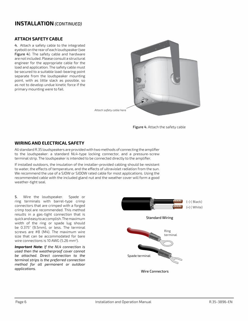
Attach safety cable here
Figure 4. Attach the safety cable
WIRING AND ELECTRICAL SAFETYAll standard R.35 loudspeakers are provided with two methods of connecting the amplifier to the loudspeaker: a standard NL4-type locking connector, and a pressure-screw terminal strip. The loudspeaker is intended to be connected directly to the amplifier.
If installed outdoors, the insulation of the installer-provided cabling should be resistant to water, the effects of temperature, and the effects of ultraviolet radiation from the sun. We recommend the use of a SJOW or SJOOW rated cable for most applications. Using the recommended cable with the included gland nut and the weather cover will form a good weather-tight seal.
ATTACH SAFETY CABLE4. Attach a safety cable to the integrated eyebolt on the rear of each loudspeaker (see Figure 4). The safety cable and hardware are not included. Please consult a structural engineer for the appropriate cable for the load and application. The safety cable must be secured to a suitable load-bearing point separate from the loudspeaker mounting point, with as little slack as possible, so as not to develop undue kinetic force if the primary mounting were to fail.
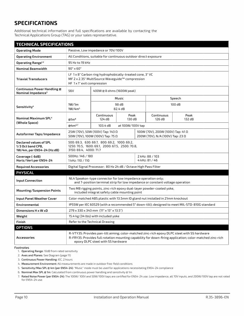
Wire Connectors
Ring terminal
Spade terminal
Standard Wiring
(–) ( Black)
(+) ( White)
5. Wire the loudspeaker. Spade or ring terminals with barrel-type crimp connectors that are crimped with a forged crimp tool are recommended. This method results in a gas-tight connection that is quick and easy to accomplish. The maximum width of the ring or spade lug should be 0.375" (9.5mm), or less. The terminal screws are #8 (M4). The maximum wire size that can be accommodated for bare wire connections is 10 AWG (5.26 mm2).
Important Note: If the NL4 connection is used then the weatherproof cover cannot be attached. Direct connection to the terminal strips is the preferred connection method for all permanent or outdoor applications.
INSTALLATION (CONTINUED)

R.35-3896-EN Installation and Operation Manual Page 7
IMPORTANT: The gland nut, weather cover and all of the attachment screws must be used in outdoor and
indoor harsh environment applications. Without these, the loudspeaker will not have the stated weather-resistant rating and may negate the warranty.
IMPORTANT: All electrical installation connections for loudspeaker lines are subject to all
applicable governmental building and fire codes. The selection of appropriate electrical hardware to interface with the R SERIES loudspeaker lies solely with the installation professional. Community recommends that an appropriately licensed engineer, electrician, or other qualified professional identify and select the appropriate conduit, fittings, wire, etc. for the installation.
DANGER: The output power capabilities of audio amplifiers present a danger to installers
especially in 70-volt and 100-volt distributed systems. To minimize the risk of electric shock from loudspeaker connecting cables, confirm that the power amplifiers are turned “off" before connecting loudspeaker cable(s) to the loudspeaker or amplifier. Always follow local electrical codes and proper electrical safety procedures.
1+
1–
2+
2–
+
–
from Amplifier
NL4-Type Connector
Figure 5. R.35 input panel
Music / Voice
Switch
NL4
Must remove jumper, or move it to the bottom terminals, for 8Ω operation (see arrow below)
Terminal Strip Follow label to
determine correct (+) terminal
connection
INPUT PANEL CONNECTIONS6. Insert the cable through the gland nut and weather cover and wire the unit for your system voltage. Refer to the label - see Figure 5. There is a preinstalled jumper that should be left in the marked position for 70/100V use, or moved to the bottom terminals for 8Ω operation. Failure to do so can result in damage to the loudspeaker and/or amplifier. Set the Music/Voice switch to the desired position. The NL4 connection can only be used for low impedance 8Ω operation.
Figure 6. Weather cover attachment
Weather Cover
Gasket
Gland Nut (Barrel)
Pan Head Screws
Input panelWire
FINAL ASSEMBLY AND TESTING 7. Secure the gland nut to the weather cover. Align the weather cover with the holes and attach using the provided pan head screws. See Figure 6.
8. All provided hardware (or other approved replacement) must be installed in order to maintain weather-resistance and preserve the product warranty.
9. Power and test the system.
INSTALLATION (CONTINUED)

Page 8 Installation and Operation Manual R.35-3896-EN
Figure 7. Remove grille
Remove grille
Insert thin blade of screwdriver between frame and enclosure and move down seam while twisting to loosen grille
FIELD SERVICERemove the loudspeaker from service to ease repair and avoid any exposure of internal components to the elements. Any driver or crossover service required is accessed from the front of the enclosure by first removing the front grille and then unscrewing and removing the horn assembly. Take note of wiring positions prior to removing any drivers from the loudspeaker. In order to maintain the weather resistance, components and assemblies must not remain removed from the loudspeaker any longer than needed for replacement. Extended exposure could cause failures and void the warranty on the loudspeaker.
1. Remove the grille. Refer to illustrations in Figure 7. Remove the screws securing the grille to the enclosure. The grille frame locks into the enclosure frame. Carefully insert a thin flat bladed screwdriver between the grille frame and the enclosure frame while gently pressing down on the grille. Starting at the top and moving down, twist the blade to release the grille from the frame. Repeat as necessary to release the other side and remove the grille.
2. Remove the screws holding the horn assembly to the enclosure and replace or service the components as necessary.
3. Replace the driver assembly securing it with all of the original hardware. Push the grille frame into place - one side and then the other, ensuring that the frames are fully seated. The grille should easily snap into place. Secure the grille with screws (in the same corner locations).
MAINTENANCE
Remove any screws securing the grille

R.35-3896-EN Installation and Operation Manual Page 9
MAINTAINING WEATHER RESISTANCEGUIDELINES FOR OUTDOOR USEThe R.35-3896-EN is suitable for outdoor installation when used as recommended.
• Always orient the loudspeaker so the mouth of the horn is, at a minimum, pointing at least 5 degrees downward. Failure to do this could result in water collecting inside the enclosure under extreme weather conditions.
• Be careful not to scratch or scrape the finish on the grille, yoke, or enclosure.
• All mounting holes must be sealed off with the stainless steel bolts, washers, and rubber washers supplied. If, for any reason, these bolts must be removed, seal off the hole with silicone caulking or some other suitable weather-tight sealant.
• The rubber washers supplied with the mounting bolts must always seat against the enclosure.
• The grille assembly is designed to prevent normal and wind-driven rain from directly entering the mouth of the loudspeaker. The grille is not designed to withstand such things as being directly sprayed from a hose; therefore this should be avoided.
• If you use any hardware in place of hardware provided with your R SERIES loudspeaker, it should also be made of stainless steel.
ACCESSORIESR-VTY35 VARY-TILT YOKE FOR R.35
R-FRY35 FULL ROTATION YOKE FOR R.35
EC STATEMENT OF CONFORMITYThis document confirms that the range of products of Community Professional Loudspeakers bearing the CE label meet all the requirements laid down by the Member States Council for adjustment of legal requirements, furthermore the products comply with the rules and regulations referring to the electromagnetic compatibility of devices from 16 April 2016.
The Community Professional Loudspeaker products bearing the CE label comply with the following directives: Low Voltage Directive 2014/35/EU and the Waste from Electrical Equipment Directive 2002/96/EC RoHS.
The authorized declaration and compatibility certification resides with the manufacturer and can be viewed upon request. The responsible manufacturer is the company:
Community Light & Sound 333 East Fifth Street, Chester, PA 19013 USA Phone: 1+610-876-3400 • www.communitypro.com
Provides pan-tilt operation. Zinc-rich epoxy dual-layer powder-coated steel with hardware, color-matched to loudspeaker.
Provides full rotation mounting capability for down-firing application (i.e. top of press box). Zinc-rich epoxy dual-layer powder-coated steel with hardware, color-matched to loudspeaker.
Page 10 Installation and Operation Manual R.35-3896-EN
SPECIFICATIONSAdditional technical information and full specifications are available by contacting the Technical Applications Group (TAG) or your sales representative.
TECHNICAL SPECIFICATIONSOperating Mode Passive, Low impedance or 70V/100V
Operating Environment All Conditions, suitable for continuous outdoor direct exposure
Operating Range1,2 95 Hz to 19 kHz
Nominal Beamwidth 90° x 60°
Triaxial TransducersLF 1 x 8" Carbon ring hydrophobically-treated cone, 3" VCMF 2 x 2.35" MultiSource Waveguide™ compression HF 1 x 1" exit compression
Continuous Power Handling @ Nominal Impedance3 56V 400W @ 8 ohms (1600W peak)
Music Speech
Sensitivity41W/1m1W/4m5
98 dB82.4 dB
100 dB
Nominal Maximum SPL4 (Whole Space)
@1m6 Continuous
124 dBPeak
130 dBContinuous
126 dBPeak
132 dB
@4m5,7 103.4 dB at 100W/100V tap
Autoformer Taps/Impedance25W (70V), 50W (100V) Tap: 143 Ω50W (70V), 100W (100V) Tap: 75 Ω
100W (70V), 200W (100V) Tap: 41 Ω200W (70V), N/A (100V) Tap: 23 Ω
Declared values of SPL 1/3 Oct band CPB, 1W/4m, per EN54-24 (Hz:dB)
500: 69.3, 630: 69.7, 800: 69.2, 1000: 69.2, 1250: 70.5, 1600: 69.1, 2000: 67.5, 2500: 70.8, 3150: 69.4, 4000: 71.7
Coverage (-6dB) Horiz/Vert per EN54-24
500Hz: 146 / 180 1 kHz: 110 / 110
2 kHz: 88 / 103 4 kHz: 81 / 46
Required Accessories Digital Signal Processor; 80 Hz 24 dB / Octave High Pass Filter
PHYSICAL
Input Connection NL4 Speakon-type connector for low impedance operation only;
and 7-position terminal strip for low impedance or constant voltage operation
Mounting/Suspension PointsTwo M8 rigging points, zinc-rich epoxy dual-layer powder-coated yoke,
included integral safety cable mounting point
Input Panel Weather Cover Color-matched ABS plastic with 13.5mm ID gland nut installed in 21mm knockout
Environmental IP55W per IEC 60529 (with a recommended 5° down-tilt); designed to meet MIL-STD-810G standard
Dimensions H x W xD 279 x 330 x 343 mm (11" x 13" x 13.5")
Weight 15.4 kg (34 lbs) with included yoke
Finish Refer to the Technical Drawing
OPTIONS
AccessoriesR-VTY35: Provides pan-tilt aiming; color-matched zinc-rich epoxy DLPC steel with SS hardwareR-FRY35: Provides full rotation mounting capability for down-firing application; color-matched zinc-rich
epoxy DLPC steel with SS hardware
Footnotes1. Operating Range: 10dB from rated sensitivity
2. Axes and Planes: See Diagram (page 11)
3. Continuous Power Handling: IEC, 2 hours
4. Measurement Environment: All measurements are made in outdoor free-field conditions
5. Sensitivity/Max SPL @ 4m (per EN54-24): "Music" mode must be used for applications necessitating EN54-24 compliance
6. Nominal Max SPL @ 1m: Calculated from continuous power handling and sensitivity @ 1m
7. Rated Noise Power (per EN54-24): The 100W/ 100V and 50W/100V taps are certified for EN54-24 use. Low impedance, all 70V inputs, and 200W/100V tap are not rated for EN54-24 use.

R.35-3896-EN Installation and Operation Manual Page 11
TECHNICAL DRAWING / DIMENSIONS / FINISH
AXES AND PLANES
H x W x D 279 x 330 x 343 mm (11" x 13" x 13.5")
Unit Weight 15.4 kg (34 lbs) with included yoke
Shipping Weight 18.1 kg (40 lbs)
SidesFront
Top
Yoke Hole Dimensions
11" (279mm)
13" (330mm)
13.5" (343mm)
8.22" (209mm)2.6" (66mm)
Ø 0.35" (Ø 9mm)8 places
6.06" (154mm) Ø 0.51" (Ø 13mm)
1" (25mm)
3.17" (81mm)
M8 Hang Point / Center of Gravity
12.12" (308mm)
8.54" (217mm)
2.6" (66mm)
1.58" (40mm)
4.65" (118mm)
0.98" (25mm)
4.65" (118mm)
5.5" (140mm)
0.84" (21mm)
Center of Gravity
Center of Load
Center of Gravity
Grille 3-layer Weather-Stop™ featuring hydrophobically-treated polyester mesh, foam, zinc-rich powder-coated perforated aluminum color-matched to enclosure
Enclosure / Finish ABS plastic, matte finish, Light Grey (RAL # 7038)
1. Reference Plane (red) is coincident with the center of the loudspeaker grille
2. Reference Axis (black) perpendicular to the reference plane, passing through the center of the grille
3. Vertical Plane (blue) intersects the reference plane at a right angle including the reference axis and the center point of the cabinet's front radius
4. Horizontal Plane (green) intersects the reference plane at a right angle and includes the reference axis1
2
4
3

Community Professional Loudspeakers333 East Fifth Street, Chester, PA 19013-4511 USAPhone (610) 876-3400 • Fax (610) 874-0190www.communitypro.com
©2018 Community Professional Loudspeakers # 114678 v:3.1 23JUL2018
Note: Every effort has been made to insure that the information contained in this manual was complete and accurate at the time of printing. However, due to ongoing technical advances, changes or modifications may have occurred that are not covered in this manual. The latest version is available at communitypro.com.
PERFORMANCEUSE A DIGITAL SIGNAL PROCESSORFor best performance, loudspeaker protection and system longevity, a digital signal processor (DSP ) should be used with all R SERIES loudspeakers. Community's dSPEC226 processor(s) and Resyn® software contain all of the information (high pass filters, limiters, factory tunings) and DSP settings to fully optimize your system. For more information on installing and operating your R SERIES loudspeaker, please contact our Technical Applications Group (TAG) at [email protected], or by phone at 610-876-3400 or toll-free (within the US and Canada) at 800-523-4934.
WARRANTY INFORMATIONTRANSFERABLE WARRANTY “(LIMITED)" VALID IN THE USA ONLYThe R SERIES loudspeakers are designed and backed by Community Professional Loudspeakers. For complete warranty information within the USA please refer to www.communitypro.com/warranty-statement. Please call 610-876-3400 or visit the website to locate your nearest Authorized Field Service Station. For Factory Service call 610-876-3400. You must obtain a Return Authorization (R/A) number prior to the return of your product for factory service.
WARRANTY INFORMATION AND SERVICE FOR COUNTRIES OTHER THAN THE USATo obtain specific warranty information and available service locations for countries other than the United States of America, contact the authorized Community Distributor for your specific country or region.