Embed Size (px)
Citation preview
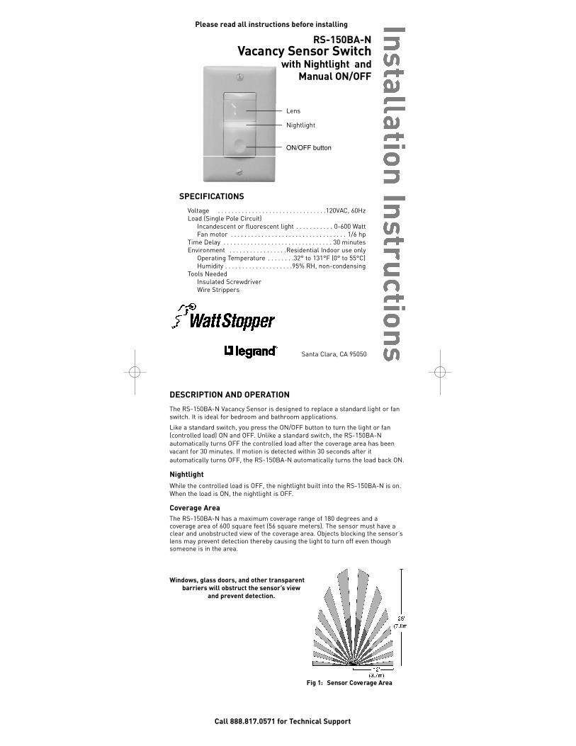
DESCRIPTION AND OPERATIONThe RS-150BA-N Vacancy Sensor is designed to replace a standard light or fanswitch. It is ideal for bedroom and bathroom applications.
Like a standard switch, you press the ON/OFF button to turn the light or fan(controlled load) ON and OFF. Unlike a standard switch, the RS-150BA-Nautomatically turns OFF the controlled load after the coverage area has beenvacant for 30 minutes. If motion is detected within 30 seconds after itautomatically turns OFF, the RS-150BA-N automatically turns the load back ON.
NightlightWhile the controlled load is OFF, the nightlight built into the RS-150BA-N is on.When the load is ON, the nightlight is OFF.
Coverage Area The RS-150BA-N has a maximum coverage range of 180 degrees and acoverage area of 600 square feet (56 square meters). The sensor must have aclear and unobstructed view of the coverage area. Objects blocking the sensor’slens may prevent detection thereby causing the light to turn off even thoughsomeone is in the area.
Windows, glass doors, and other transparentbarriers will obstruct the sensor’s view
and prevent detection.
Call 888.817.0571 for Technical Support
Fig 1: Sensor Cove rage Are a
R S - 1 5 0 B A - NVa cancy Sensor Switc h
with Nightlight andManual ON/OFF
SPECIFICATIONSVoltage . . . . . . . . . . . . . . . . . . . . . . . . . . . . . . . .120VAC, 60HzLoad (Single Pole Circuit)
Incandescent or fluorescent light . . . . . . . . . . . 0-600 Watt Fan motor . . . . . . . . . . . . . . . . . . . . . . . . . . . . . . . . . . 1/6 hp
Time Delay . . . . . . . . . . . . . . . . . . . . . . . . . . . . . . . . 30 minutesEnvironment . . . . . . . . . . . . . . . . .Residential Indoor use only
Operating Temperature . . . . . . . .32° to 131°F (0° to 55°C)Humidity . . . . . . . . . . . . . . . . . . . .95% RH, non-condensing
Tools NeededInsulated ScrewdriverWire Strippers
Please read all instructions before installing
Santa Clara, CA 95050
Lens
ON/OFF button
Nightlight
ii_RS-150BA-N 06015r2 WEB.qxd 3/5/07 9:57 AM Page 1
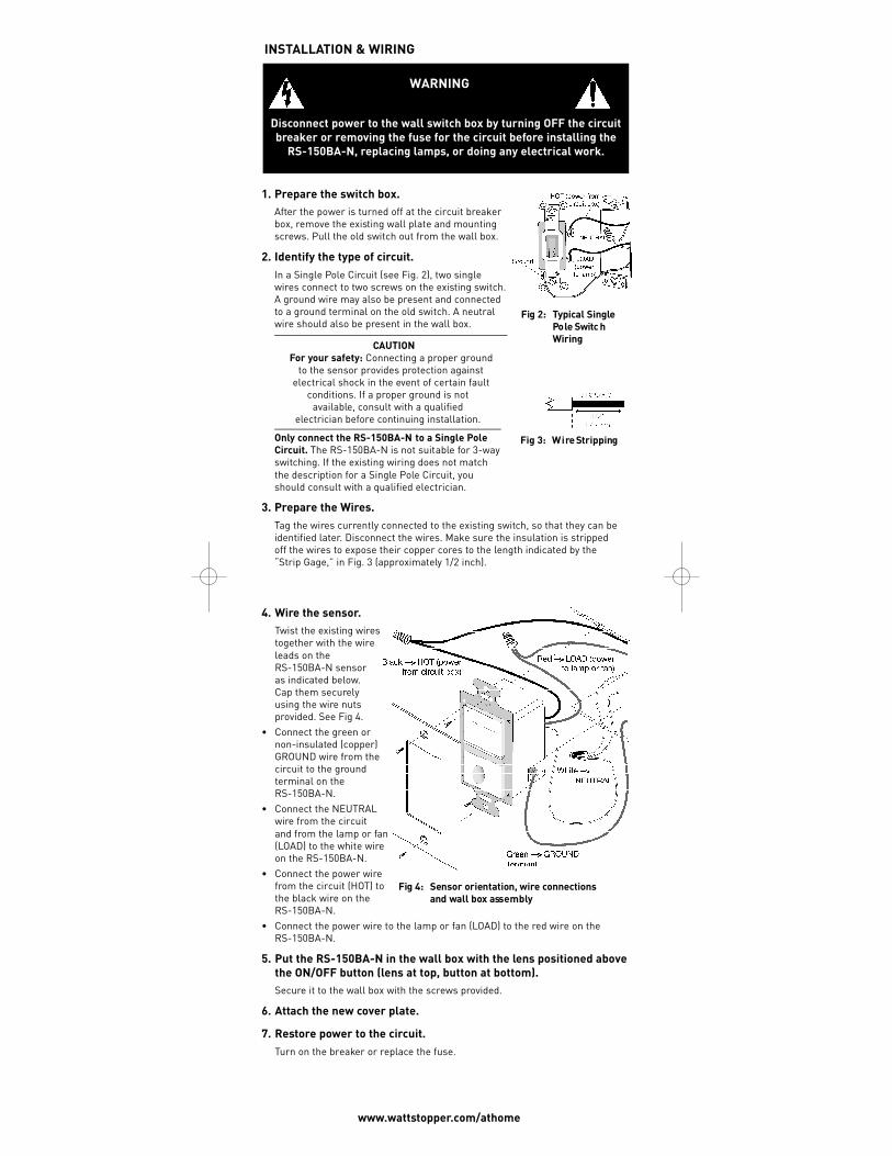
4. Wire the sensor.Twist the existing wirestogether with the wireleads on theRS-150BA-N sensor as indicated below.Cap them securelyusing the wire nutsprovided. See Fig 4.
• Connect the green ornon-insulated (copper)GROUND wire from thecircuit to the groundterminal on theRS-150BA-N.
• Connect the NEUTRALwire from the circuit and from the lamp or fan(LOAD) to the white wireon the RS-150BA-N.
• Connect the power wirefrom the circuit (HOT) tothe black wire on theRS-150BA-N.
• Connect the power wire to the lamp or fan (LOAD) to the red wire on theRS-150BA-N.
5. Put the RS-150BA-N in the wall box with the lens positioned abovethe ON/OFF button (lens at top, button at bottom). Secure it to the wall box with the screws provided.
6. Attach the new cover plate.
7. Restore power to the circuit. Turn on the breaker or replace the fuse.
Fig 4: Sensor orientation, wire co n n e c t i o n sand wall box ass e m b ly
WARNING
Disconnect power to the wall switch box by turning OFF the circuitbreaker or removing the fuse for the circuit before installing the
RS-150BA-N, replacing lamps, or doing any electrical work.
INSTALLATION & WIRING
1. Prepare the switch box.After the power is turned off at the circuit breakerbox, remove the existing wall plate and mountingscrews. Pull the old switch out from the wall box.
2. Identify the type of circuit.In a Single Pole Circuit (see Fig. 2), two singlewires connect to two screws on the existing switch.A ground wire may also be present and connectedto a ground terminal on the old switch. A neutralwire should also be present in the wall box.
CAUTIONFor your safety: Connecting a proper ground
to the sensor provides protection againstelectrical shock in the event of certain fault
conditions. If a proper ground is not available, consult with a qualified
electrician before continuing installation.
Only connect the RS-150BA-N to a Single PoleCircuit. The RS-150BA-N is not suitable for 3-wayswitching. If the existing wiring does not matchthe description for a Single Pole Circuit, youshould consult with a qualified electrician.
3. Prepare the Wires.Tag the wires currently connected to the existing switch, so that they can beidentified later. Disconnect the wires. Make sure the insulation is strippedoff the wires to expose their copper cores to the length indicated by the“Strip Gage,” in Fig. 3 (approximately 1/2 inch).
www.wattstopper.com/athome
Fig 2: Ty p i cal SinglePo le Switc hW i r i n g
Fig 3: W i re Stripping
ii_RS-150BA-N 06015r2 WEB.qxd 3/5/07 9:57 AM Page 2
2800 De La Cruz Boulevard, Santa Clara, CA 95050Technical Support: 888.817.0571www.wattstopper.com/athome
06015r2 2/2007
TROUBLESHOOTING
To test the detection coverage:During the TEST mode, the controlled load turns ON for 5 seconds each timethe sensor detects occupancy.
1. Press and hold the ON/OFF button. After 10 seconds the nightlight flashes.The load turns ON if it was not already ON. The sensor is now in a TESTmode that lasts 5 minutes. (You can end the TEST mode sooner by pressingthe ON/OFF button for another 10 seconds).
2. Move out of the coverage area or stand very still. The controlled load turnsOFF after 5 seconds, if no motion is detected.
3. Move in the coverage area. The nightlight flashes each time the sensordetects motion and the controlled load turns ON for 5 seconds. After 5 seconds expire without motion detection, the load turns OFF.The load turns ON automatically with the next motion detection and stays onfor 5 seconds.
4. Repeat as necessary to ensure that the desired coverage areas are withindetection range.
Load will not turn ON (nightlight is visible):Press ON/OFF button. The load should turn ON. If not:• Check the light bulb and/or motor switch on the fan mechanism.• Turn off power to the circuit then check wire connections.
Load will not turn ON (nightlight is NOT visible): • Check the light bulb and/or motor switch on the fan mechanism.• Make certain that the circuit breaker is on and functioning.• Turn off power to the circuit then check wire connections. • Call 888.817.0571 for technical support.
Load will not turn OFF:• Make sure no motion is occurring in the coverage area until the 30 minute
time delay expires. • Hot air currents and heat radiating devices can cause false detection. Make
sure the sensor is at least 6 feet (2 meters) away from devices that are asignificant heat source (e.g., heater, heater vent, high wattage light bulb).
• Press the ON/OFF button. If load does not turn off, turn off power to thecircuit then check wire connections.
WARRANTY INFORMATIONWatt Stopper/Legrand warranties its products to be free of defects in materialsand workmanship for a period of five (5) years. There are no obligations orliabilities on the part of Watt Stopper/Legrand for consequential damagesarising out of, or in connection with, the use or performance of this product orother indirect damages with respect to loss of property, revenue or profit, orcost of removal, installation or reinstallation.
PleaseRecycle
ii_RS-150BA-N 06015r2 WEB.qxd 3/5/07 9:58 AM Page 3
R S - 1 5 0 B A - NSensor de Desocupación
con Luz Nocturna y co n t rol manual de E N C E N D I D O / A PAGA D O
Por favor leer todas las instruccionesantes de realizar la instalación.
Llame al 888.817.0571 para recibir asistencia técnica
Lente
Botón deENCENDIDO/APAGADO
Luz Nocturna
ESPECIFICACIONESVoltaje . . . . . . . . . . . . . . . . . . . . . . . . . . . . . . . . . . . .120VAC, 60HzCarga (Circuito unipolar)
Lámparas incandescentes o fluorescentes . . . . . .0-600 WattsUn motor . . . . . . . . . . . . . . . . . . . . . . . . . . . . . . . . . . . . . . . 1/6hp
Retardo de Apagado . . . . . . . . . . . . . . . . . . . . . . . . . . . . . .30 minutosCondiciones de operación . .Solo para uso residencial en interiores
Temperatura . . . . . . . . . . . . . . . . .entre 32° y 131°F (0° y 55°C)Humedad . . . . . . . . . .95% humedad relativa, sin condensación
Herramientas necesariasDesatornillador con aislamientoPeladora de cable
DESCRIPCIÓN Y OPERACIÓNEl sensor de desocupación RS-150BA-N sustituye un interruptor de luzconvencional o el interruptor de un ventilador. Es ideal para dormitorios ybaños.
Igual que con un interruptor convencional, usted presiona el botón deENCENDIDO/APAGADO para encender o apagar la luz o ventilador (cargacontrolada). Sin embargo, el RS-150BA-N apagará automáticamente la cargacontrolada cuando el área de cobertura ha permanecido desocupada por 30minutos. Si se detecta movimiento durante los siguientes 30 segundos despuésde que la carga se ha apagado automáticamente, el RS-150BA-N la encenderánuevamente en forma también automática.
Luz NocturnaCuando la carga controlada se encuentra apagada, la Luz Nocturna delRS-150BA-N se encuentra encendida. Cuando por el contrario la cargacontrolada se encuentra encendida la Luz Nocturna se encuentra apagada.
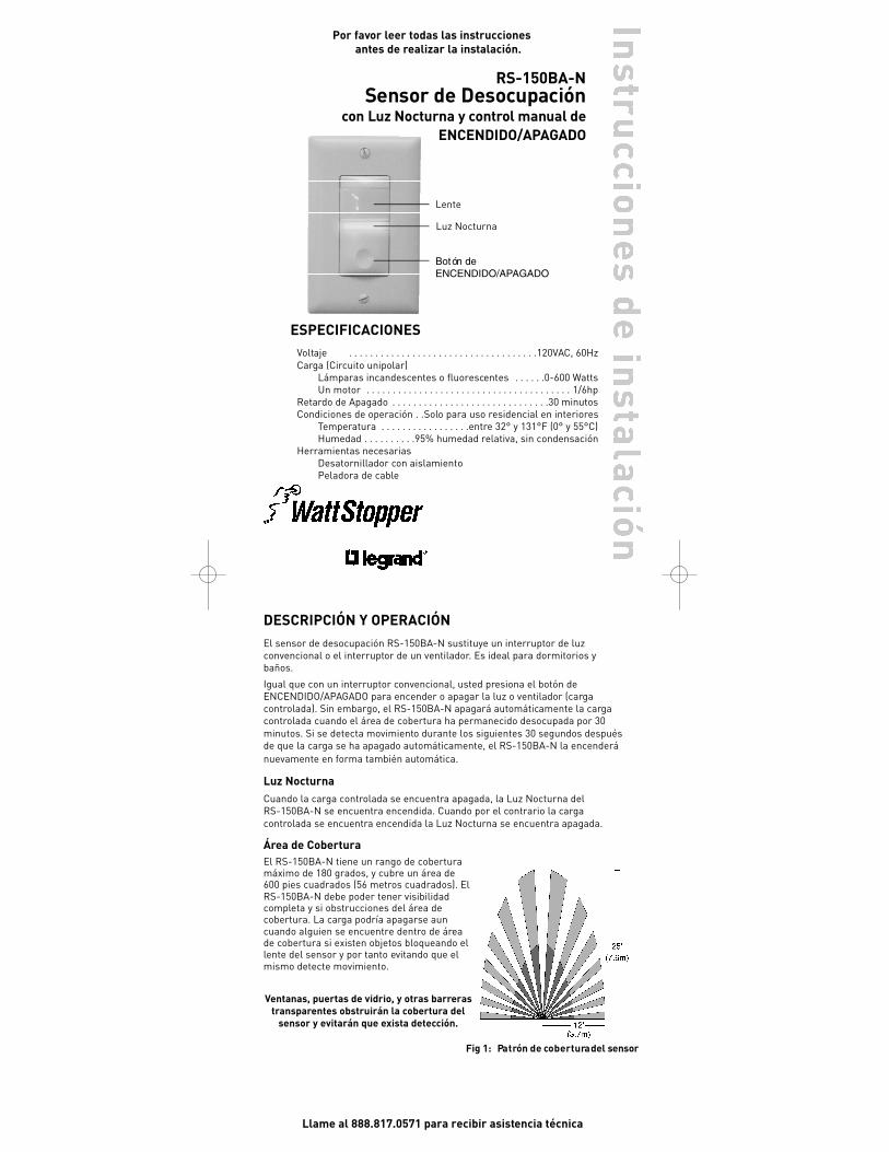
Área de CoberturaEl RS-150BA-N tiene un rango de coberturamáximo de 180 grados, y cubre un área de600 pies cuadrados (56 metros cuadrados). ElRS-150BA-N debe poder tener visibilidadcompleta y si obstrucciones del área decobertura. La carga podría apagarse auncuando alguien se encuentre dentro de áreade cobertura si existen objetos bloqueando ellente del sensor y por tanto evitando que elmismo detecte movimiento.
Ventanas, puertas de vidrio, y otras barrerastransparentes obstruirán la cobertura del
sensor y evitarán que exista detección.
Fig 1: Pa t rón de co b e r t u ra del sensor
ii_RS-150BA-N 06015r2 WEB.qxd 3/5/07 9:58 AM Page 4
www.wattstopper.com/athome
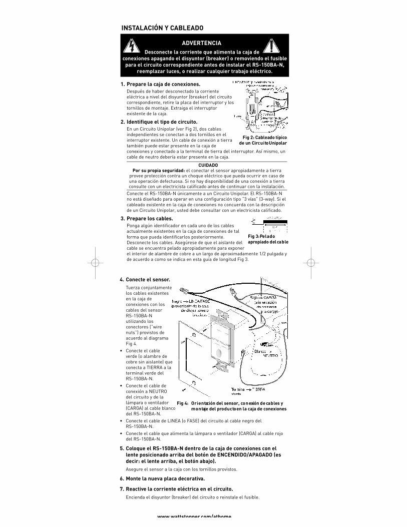
4. Conecte el sensor.Tuerza conjuntamentelos cables existentesen la caja deconexiones con loscables del sensorRS-150BA-Nutilizando losconectores (“wirenuts”) provistos deacuerdo al diagramaFig 4.
• Conecte el cableverde (o alambre decobre sin aislante) queconecta a TIERRA a laterminal verde delRS-150BA-N.
• Conecte el cable deconexión a NEUTROdel circuito y de lalámpara o ventilador(CARGA) al cable blancodel RS-150BA-N.
• Conecte el cable de LINEA (o FASE) del circuito al cable negro delRS-150BA-N.
• Conecte el cable que alimenta la lámpara o ventilador (CARGA) al cable rojodel RS-150BA-N.
5. Coloque el RS-150BA-N dentro de la caja de conexiones con ellente posicionado arriba del botón de ENCENDIDO/APAGADO (esdecir: el lente arriba, el botón abajo). Asegure el sensor a la caja con los tornillos provistos.
6. Monte la nueva placa decorativa.
7. Reactive la corriente eléctrica en el circuito. Encienda el disyuntor (breaker) del circuito o reinstale el fusible.
ADVERTENCIADesconecte la corriente que alimenta la caja de
conexiones apagando el disyuntor (breaker) o removiendo el fusiblepara el circuito correspondiente antes de instalar el RS-150BA-N,
reemplazar luces, o realizar cualquier trabajo eléctrico.
INSTALACIÓN Y CABLEADO
1. Prepare la caja de conexiones.Después de haber desconectado la corrienteeléctrica a nivel del disyuntor (breaker) del circuitocorrespondiente, retire la placa del interruptor y lostornillos de montaje. Extraiga el interruptorexistente de la caja.
2. Identifique el tipo de circuito.En un Circuito Unipolar (ver Fig 2), dos cablesindependientes se conectan a dos tornillos en elinterruptor existente. Un cable de conexión a tierratambién puede estar presente en la caja deconexiones y conectado a la terminal de tierra del interruptor. Así mismo, uncable de neutro debería estar presente en la caja.
CUIDADOPor su propia seguridad: el conectar el sensor apropiadamente a tierra
provee protección contra un choque eléctrico que pueda ocurrir en caso deuna operación defectuosa. Si no hay disponibilidad de una conexión a tierraconsulte con un electricista calificado antes de continuar con la instalación.
Conecte el RS-150BA-N únicamente a un Circuito Unipolar. El RS-150BA-Nno está diseñado para operar en una configuración tipo “3 vías” (3-way). Si elcableado existente en la caja de conexiones no concuerda con la descripciónde un Circuito Unipolar, usted debe consultar con un electricista calificado.
3. Prepare los cables.Ponga algún identificador en cada uno de los cablesactualmente existentes en la caja de conexiones de talforma que pueda identificarlos posteriormente.Desconecte los cables. Asegúrese de que el aislante delcable se encuentra pelado apropiadamente para exponerel interior de alambre de cobre a un largo de aproximadamente 1/2 pulgada yde acuerdo a como se indica en esta guía de longitud Fig 3.
Fig 4: O r i e n tación del sensor, co n exión de ca b les ym o n taje del pro d u c to en la caja de co n ex i o n e s
Fig 2: Cableado típicode un Circ u i to Unipolar
Fig 3: Pe l a d oa p ropiado del ca b le
ii_RS-150BA-N 06015r2 WEB.qxd 3/5/07 9:58 AM Page 5
INFORMACIÓN SOBRE LA GARANTÍA DE PRODUCTOWatt Stopper/Legrand garantiza que sus productos están libres de defectos ensus materiales y ensamble por un período de cinco (5) años. No existenobligaciones o responsabilidades por parte de Watt Stopper / Legrand pordaños ocasionados por o en conexión con el uso o desempeño de este productou otros daños indirectos en materia de pérdida de propiedad, ventas oganancias, o costos por retiro, instalación o desinstalación.
2800 De La Cruz Boulevard, Santa Clara, CA 95050Asistencia Técnica: 888.817.0571
www.wattstopper.com/athome06015r2 2/2007
SOLUCIÓN DE PROBLEMAS
Para probar la cobertura del sensor:Durante el modo de PRUEBA, la carga controlada por el sensor se encenderápor 5 segundos cada vez que el sensor detecta movimiento.
1. Oprima y mantenga oprimido el botón de ENCENDIDO/APAGADO. Despuésde transcurridos 10 segundos la Luz Nocturna parpadeará. La carga seencenderá si no estaba ya encendida. El sensor se encuentra ahora en modode PRUEBA, el cual durará 5 minutos (usted puede sacar el sensor de modode PRUEBA en cualquier momento presionando el botón deENCENDIDO/APAGADO por otros 10 segundos más).
2. Movilícese fuera del área de cobertura o permanezca inmóvil. La cargacontrolada se apagará después de 5 segundos si el sensor no detectamovimiento.
3. Movilícese dentro del área de cobertura. La Luz Nocturna parpadeará cadavez que el sensor detecte movimiento mientras que la carga controlada seenciende por 5 segundos. Después de transcurridos 5 segundos de no detección, la carga se apagará.La carga se enciende automáticamente con la próxima detección y semantiene encendida por otros 5 segundos.
4. Repita según sea necesario para asegurarse que el área que se desea cubrircon el sensor se encuentra dentro del rango de cobertura del mismo.
La carga no se enciende, pero la Luz Nocturna del sensor SI es visible:Presione el botón de ENCENDIDO/APAGADO. La luz controlada por el sensordeberá encenderse. Si no es así:
• Revise el bombillo (lámpara incandescente) y/o el interruptor del motor delventilador.
• Desconecte la corriente del circuito en cuestión a nivel del disyuntor(breaker) y revise las conexiones de los cables.
La carga no se enciende y la Luz Nocturna del sensor NO es visible:• Revise el bombillo (lámpara incandescente) y/o el interruptor del motor del
ventilador.• Asegúrese de que el disyuntor (breaker) del circuito funcione y que se
encuentre encendido.• Desconecte la corriente del circuito en cuestión desde el disyuntor (breaker)
y revise las conexiones de los cables.• Llame al 888.817.0571 para recibir asistencia técnica.
La carga no se apaga:• Asegúrese que no hay movimiento a detectar dentro del área de cobertura
del sensor hasta que el tiempo de retardo de apagado de 30 minutostranscurra.
• Corrientes de aire caliente y dispositivos emisores de calor pueden ocasionarfalsas detecciones. Asegúrese que el sensor se encuentra alejado al menosseis pies (2 metros) de dispositivos que sean fuentes considerables de calor(por ejemplo: radiadores, salidas de aire caliente, lámparas de alta potencia).
• Presione el botón de ENCENDIDO/APAGADO. Si la carga no se apaga,desconecte la corriente al circuito desde el disyuntor (breaker) y revise lasconexiones de los cables.
ii_RS-150BA-N 06015r2 WEB.qxd 3/5/07 9:58 AM Page 6
![109 w] ^ 0 [ ï}Ú}²Vóÿ ÿ ÿ ÿ ÿ ÿ ÿ ÿ - Nagasaki...n n n n n n n n n n n n n n n n n n n n n n n n n n n n n n n n n n n n n n n n n n n n n n n n n n n n n n n n n n n n](https://img.pdfslide.us/doc/110x75/5f36fb8f1f26d128d06b20dc/109-w-0-v-nagasaki-n-n-n-n-n-n-n-n-n.jpg)