Embed Size (px)
Citation preview
R RR R
R RR R
R RR R
R RR R
R RR R
R RR R
R RR R
R RR R
R RR R
R RR R
R RR R
R RR R
R RR R
R RR R
R RR R
R RR R
R RR R
R RR R
R RR R
R RR R
R RR R
R RR R
R RR R
R RR R
R RR R
R RR R
R RR R
R RR R
R RR R
R RR R
R RR R
R RR R
R RR R
R RR R
R RR R
R RR R
R RR R
R RR
R RR
R RR
R RR
R RR
R RR
R RR
R RR
R RR
R RR
R RR
R RR
R RR
R RR
R RR
R RR
R RR
R RR
R RR
R RR
R RR
R RR
R RR
R RR
R RR
R RR
R RR
R RR
R RR
R RR
R RR
R RR
R RR
R RR
R RR
R RR
R RR
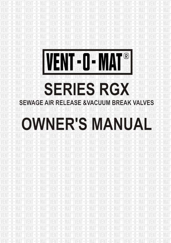
SERIES RGXSEWAGE AIR RELEASE &VACUUM BREAK VALVES
OWNER'S MANUAL
SERIES RGX
OWNER'S MANUAL
SEWAGE AIR RELEASE &VACUUM BREAK VALVES
R
R
R
R
R
R
R
R
R
R
R
R
R
R
R
R
R
R
R
R
R
R
R
R
R
R
R
R
R
R
R
R
R
R
R
R
R
R
R
R
R
R
R
R
R
R
R
R
R
R
R
R
R
R
R
R
R
R
R
R
R
R
R
R
R
R
R
R
R
R
R
R
R
R
R
R
R
R
R
R
R
R
R
R
R
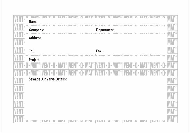
Name:
Project:
Sewage Air Valve Details:
Company: Department:
Address:
Tel: Fax:
R
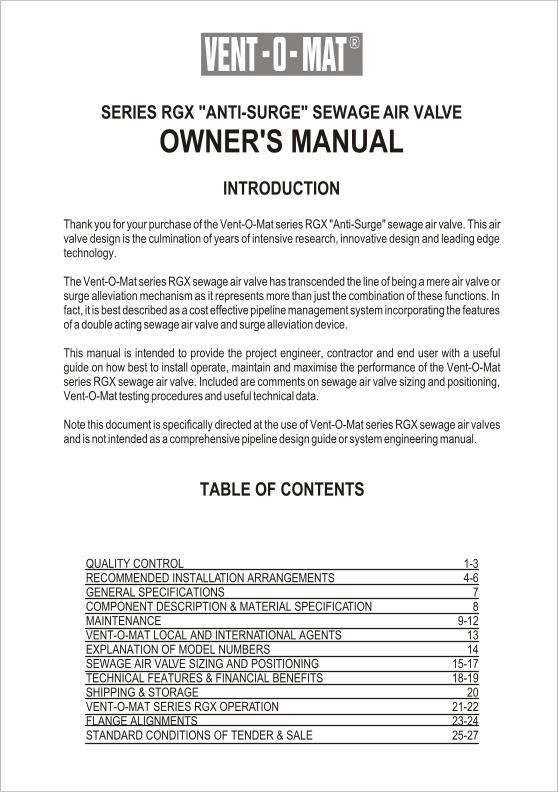
SERIES RGX "ANTI-SURGE" SEWAGE AIR VALVE
OWNER'S MANUAL
INTRODUCTION
Thank you for your purchase of the Vent-O-Mat series RGX "Anti-Surge" sewage air valve. This air valve design is the culmination of years of intensive research, innovative design and leading edge technology.
The Vent-O-Mat series RGX sewage air valve has transcended the line of being a mere air valve or surge alleviation mechanism as it represents more than just the combination of these functions. In fact, it is best described as a cost effective pipeline management system incorporating the features of a double acting sewage air valve and surge alleviation device.
This manual is intended to provide the project engineer, contractor and end user with a useful guide on how best to install operate, maintain and maximise the performance of the Vent-O-Mat series RGX sewage air valve. Included are comments on sewage air valve sizing and positioning, Vent-O-Mat testing procedures and useful technical data.
Note this document is specifically directed at the use of Vent-O-Mat series RGX sewage air valves and is not intended as a comprehensive pipeline design guide or system engineering manual.
TABLE OF CONTENTS
QUALITY CONTROLRECOMMENDED INSTALLATION ARRANGEMENTSGENERAL SPECIFICATIONSCOMPONENT DESCRIPTION & MATERIAL SPECIFICATIONMAINTENANCEVENT-O-MAT LOCAL AND INTERNATIONAL AGENTSEXPLANATION OF MODEL NUMBERSSEWAGE AIR VALVE SIZING AND POSITIONINGTECHNICAL FEATURES & FINANCIAL BENEFITSSHIPPING & STORAGEVENT-O-MAT SERIES RGX OPERATIONFLANGE ALIGNMENTSSTANDARD CONDITIONS OF TENDER & SALE
1-34-6
78
9-121314
15-1718-19
2021-2223-2425-27
R
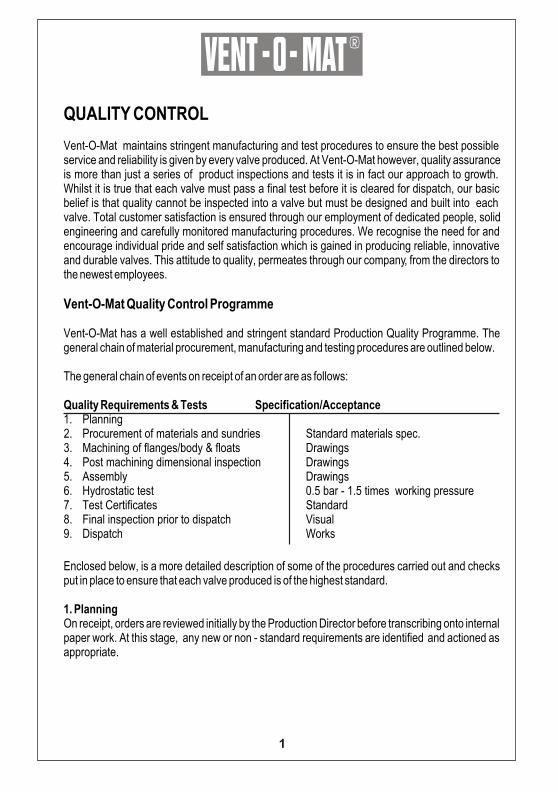
QUALITY CONTROL
Vent-O-Mat maintains stringent manufacturing and test procedures to ensure the best possible service and reliability is given by every valve produced. At Vent-O-Mat however, quality assurance is more than just a series of product inspections and tests it is in fact our approach to growth. Whilst it is true that each valve must pass a final test before it is cleared for dispatch, our basic belief is that quality cannot be inspected into a valve but must be designed and built into each valve. Total customer satisfaction is ensured through our employment of dedicated people, solid engineering and carefully monitored manufacturing procedures. We recognise the need for and encourage individual pride and self satisfaction which is gained in producing reliable, innovative and durable valves. This attitude to quality, permeates through our company, from the directors to the newest employees.
Vent-O-Mat Quality Control Programme Vent-O-Mat has a well established and stringent standard Production Quality Programme. The general chain of material procurement, manufacturing and testing procedures are outlined below. The general chain of events on receipt of an order are as follows:
Quality Requirements & Tests Specification/Acceptance1. Planning2. Procurement of materials and sundries Standard materials spec.3. Machining of flanges/body & floats Drawings4. Post machining dimensional inspection Drawings5. Assembly Drawings6. Hydrostatic test 0.5 bar - 1.5 times working pressure7. Test Certificates Standard8. Final inspection prior to dispatch Visual9. Dispatch Works
Enclosed below, is a more detailed description of some of the procedures carried out and checks put in place to ensure that each valve produced is of the highest standard.
1. Planning On receipt, orders are reviewed initially by the Production Director before transcribing onto internal paper work. At this stage, any new or non - standard requirements are identified and actioned as appropriate.
1
R
This is then passed to the Planning Department who procure the relevant materials and sundries . All correspondence relating to an order is held in the sales order file which also contains copies of all material and product test certification on completion of the order . 2. Work Instructions The Planning Department issues to the Manufacturing Department , copies of the works order , detailed piece part drawings and manufacturing route cards which indicate both manufacturing and inspection operations . Detailed method sheets are compiled for each machining operation and issued as part of the full instruction package . Any non - standard operations , such as specialised testing or marking are either detailed in the works order or the works order refers to a separately issued procedure. 3. Records The records maintained against standard products are material test certification for pressure containing parts and final product certification. In - house records are maintained in respect of components and final inspection 4. Design Control All calculations and drawings are checked and signed - off by either the Production Director or the Technical Manager. 5. Documentation and Change Control A drawing register is maintained which reflects current issue and date of drawings available. Change to the drawings is controlled by a change note system which maintains records of all changes.
Copies of modified drawings are issued to all relevant departments and are signed for on receipt . Copies of the superseded drawings are removed and destroyed . Control of process procedures, e.g. welding, is the responsibility of the Quality Assurance Manager and are issued as necessary against the specific works order.
6. Control of Inspection, Measuring and Test Equipment Regular checks are carried out on equipment being used. Pressure gauges used in product testing are tightly controlled. Each gauge is identified by a unique gauge or test stand number and the dates when calibration are due are clearly shown.
2
R
Calibration records of checks against a master standard pressure gauge are maintained. 7. Control of Purchased Materials and Services Purchased supplies usually consist of raw materials, such as stainless steel and high density polyethylene, which are procured from well established suppliers who supply as standard, material test certificates. Sub contracted processes are limited to plating operations, specialised welding and the machining of flanges. Supplier performance is judged from an analysis of the Goods Received inspection reports. All purchase orders are clearly drawn up and references are given to the required specifications. All material received is first passed to Goods Receiving Inspection for checking and acceptance. Visual inspection, verification of identification against test certification and dimensional inspection are carried out. Responsibility for the checking and signing - for the acceptance of materials test certification lies with Quality Assurance Manager. Materials are not passed to the stores until clearance has been obtained. Material is cleared to the Stores by an inspection sign off or the stores receipt note . Any reject material is segregated, marked and an inspection rejection note is raised. 8. Manufacturing Control A work packet comprising the component drawings, method sheets and route card is prepared and issued for each item or batch of items to be manufactured. The route cards indicate the intermediate and final inspection operations. A system of first off and patrol inspection is employed in addition to a 100% final inspection on all assembled products. 9. Completed Item Inspection Test Assembly of the final product is carried out using the parts issued from the warehouse having identifiable inspection clearance, with reference to the general arrangement drawings.
3
R
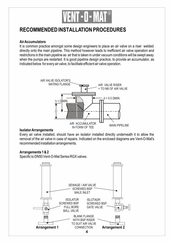
RECOMMENDED INSTALLATION PROCEDURES
Air AccumulatorsIt is common practice amongst some design engineers to place an air valve on a riser welded directly onto the main pipeline. This method however leads to inefficient air valve operation and restrictions in the main pipeline as air that is taken in under vacuum conditions will be swept away when the pumps are restarted. It is good pipeline design practice, to provide an accumulator, as indicated below for every air valve, to facilitate efficient air valve operation.
Isolator ArrangementsEvery air valve installed, should have an isolator installed directly underneath it to allow the removal of the air valve in case of repairs. Indicated on the enclosed diagrams are Vent-O-Mat's recommended installation arrangements.
Arrangements 1 & 2Specific to DN50 Vent-O-Mat Series RGX valves.
Arrangement 1 Arrangement 2
AIR ACCUMULATORIN FORM OF TEE
MAIN PIPELINE
AIR VALVE RISER= TO NB OF AIR VALVE
AIR VALVE ISOLATOR'S MATING FLANGE
d = 0.5 DMIN.h = D MIN.
D
SEWAGE / AIR VALVESCREWED BSP
MALE INLET
ISLOTAORSCREWED BSPGATE VALVE
ISOLATORSCREWED BSP
FULL BOREBALL VALVE
BLANK FLANGEWITH BSP RISER
TO SUIT AIR VALVE CONNECTION
4
R
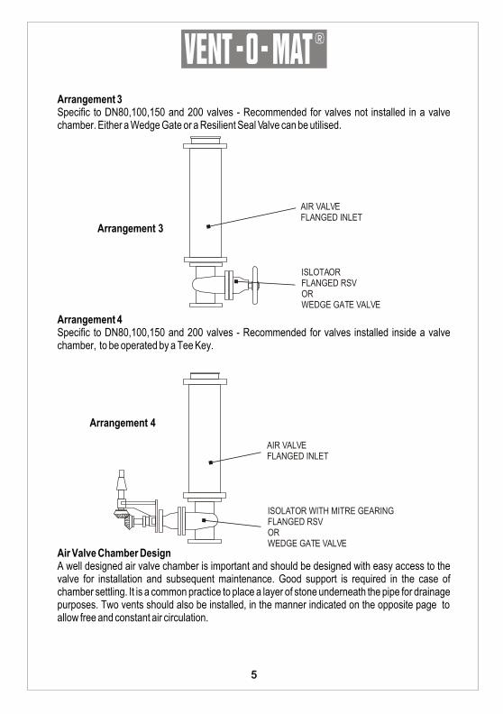
Arrangement 3Specific to DN80,100,150 and 200 valves - Recommended for valves not installed in a valve chamber. Either a Wedge Gate or a Resilient Seal Valve can be utilised.
Arrangement 3
Arrangement 4Specific to DN80,100,150 and 200 valves - Recommended for valves installed inside a valve chamber, to be operated by a Tee Key.
Arrangement 4
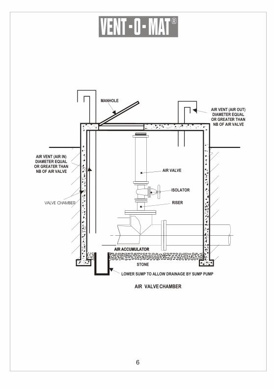
Air Valve Chamber DesignA well designed air valve chamber is important and should be designed with easy access to the valve for installation and subsequent maintenance. Good support is required in the case of chamber settling. It is a common practice to place a layer of stone underneath the pipe for drainage purposes. Two vents should also be installed, in the manner indicated on the opposite page to allow free and constant air circulation.
AIR VALVEFLANGED INLET
ISLOTAORFLANGED RSVORWEDGE GATE VALVE
AIR VALVEFLANGED INLET
ISOLATOR WITH MITRE GEARING FLANGED RSVORWEDGE GATE VALVE
5
R
6
AIR VENT (AIR IN)DIAMETER EQUAL
OR GREATER THANNB OF AIR VALVE
AIR VENT (AIR OUT)DIAMETER EQUAL
OR GREATER THANNB OF AIR VALVE
MANHOLE
STONE
LOWER SUMP TO ALLOW DRAINAGE BY SUMP PUMP
VALVE CHAMBER
AIR ACCUMULATORAIR ACCUMULATOR
AIR VALVE CHAMBER
AIR VALVE
ISOLATOR
RISER
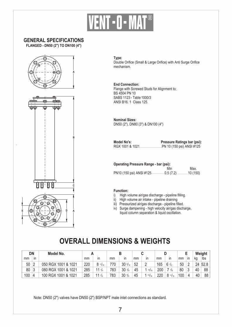
Type:Double Orifice (Small & Large Orifice) with Anti Surge Orifice mechanism.
End Connection:Flange with Screwed Studs for Alignment to;BS 4504 PN 10SABS 1123 - Table 1000/3ANSI B16. 1 Class 125.
Nominal Sizes:DN50 (2"), DN80 (3") & DN100 (4")
Model No's: Pressure Ratings bar (psi):RGX 1001 & 1021 PN 10 (150 psi) ANSI #125
Operating Pressure Range - bar (psi): Min Max.PN10 (150 psi) ANSI #125 0.5 (7.2) 10 (150)
Function:i) High volume air/gas discharge - pipeline filling.ii) High volume air intake - pipeline drainingiii) Pressurized air/gas discharge - pipeline filled.iv) Surge dampening - high velocity air/gas discharge, liquid column separation & liquid oscillation.
OVERALL DIMENSIONS & WEIGHTS
GENERAL SPECIFICATIONSFLANGED - DN50 (2") TO DN100 (4")
511 150 2 050 RGX 1001 & 1021 220 8 /16 770 30 /16 52 2 165 6 /2 50 2 24 52.871 13 780 3 080 RGX 1001 & 1021 285 11 /4 783 30 /8 45 1 /16 200 7 /8 80 3 40 887 131 11100 4 100 RGX 1001 & 1021 285 11 /4 783 30 /8 45 1 /16 220 8 /16 100 4 40 88
DN Model No. A B C D E Weight mm in mm in mm in mm in mm in mm in kg lbs
DE
C
B
A
A
R
Note: DN50 (2") valves have DN50 (2") BSP/NPT male inlet connections as standard.
7
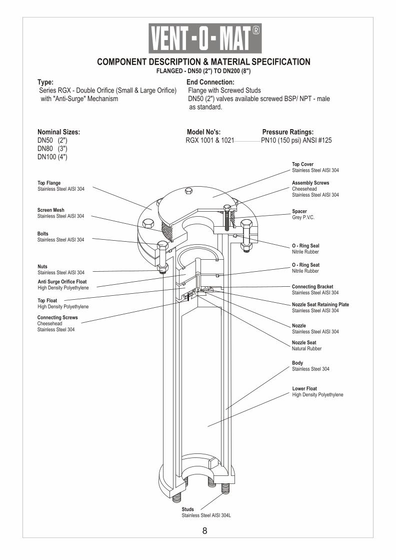
COMPONENT DESCRIPTION & MATERIAL SPECIFICATIONFLANGED - DN50 (2") TO DN200 (8")
Type: End Connection: Series RGX - Double Orifice (Small & Large Orifice) Flange with Screwed Studs with "Anti-Surge" Mechanism DN50 (2") valves available screwed BSP/ NPT - male as standard.
Nominal Sizes: Model No's: Pressure Ratings: DN50 (2") RGX 1001 & 1021 PN10 (150 psi) ANSI #125DN80 (3") DN100 (4")
Top CoverStainless Steel AISI 304
SpacerGrey P.V.C.
Assembly ScrewsCheesehead Stainless Steel AISI 304
O - Ring SealNitrile Rubber
Top FlangeStainless Steel AISI 304
Screen MeshStainless Steel AISI 304
BoltsStainless Steel AISI 304
NutsStainless Steel AISI 304
Anti Surge Orifice FloatHigh Density Polyethylene
StudsStainless Steel AISI 304L
NozzleStainless Steel AISI 304
Nozzle SeatNatural Rubber
Connecting BracketStainless Steel AISI 304
O - Ring SeatNitrile Rubber
Nozzle Seat Retaining PlateStainless Steel AISI 304
Lower FloatHigh Density Polyethylene
BodyStainless Steel 304
Top FloatHigh Density Polyethylene
Connecting ScrewsCheeseheadStainless Steel 304
R
8
R
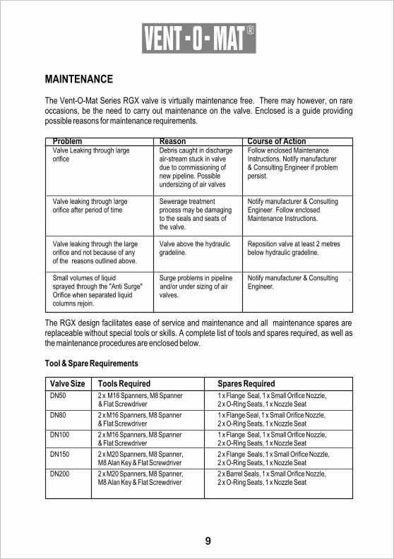
MAINTENANCE The Vent-O-Mat Series RGX valve is virtually maintenance free. There may however, on rare occasions, be the need to carry out maintenance on the valve. Enclosed is a guide providing possible reasons for maintenance requirements.
Problem Reason Course of ActionValve Leaking through large Debris caught in discharge Follow enclosed Maintenanceorifice air-stream stuck in valve Instructions. Notify manufacturer
due to commissioning of & Consulting Engineer if problemnew pipeline. Possible persist.undersizing of air valves
Valve leaking through large Sewerage treatment Notify manufacturer & Consultingorifice after period of time process may be damaging Engineer. Follow enclosed
to the seals and seats of Maintenance Instructions.the valve.
Valve leaking through the large Valve above the hydraulic Reposition valve at least 2 metres orifice and not because of any gradeline. below hydraulic gradeline.of the reasons outlined above.
Small volumes of liquid Surge problems in pipeline Notify manufacturer & Consulting .sprayed through the "Anti Surge" and/or under sizing of air Engineer.Orifice when separated liquid valves.columns rejoin.
The RGX design facilitates ease of service and maintenance and all maintenance spares are replaceable without special tools or skills. A complete list of tools and spares required, as well as the maintenance procedures are enclosed below. Tool & Spare Requirements
Valve Size Tools Required Spares Required
DN50 2 x M16 Spanners, M8 Spanner 1 x Flange Seal, 1 x Small Orifice Nozzle,& Flat Screwdriver 2 x O-Ring Seats, 1 x Nozzle Seat
DN80 2 x M16 Spanners, M8 Spanner 1 x Flange Seal, 1 x Small Orifice Nozzle,& Flat Screwdriver 2 x O-Ring Seats, 1 x Nozzle Seat
DN100 2 x M16 Spanners, M8 Spanner 1 x Flange Seal, 1 x Small Orifice Nozzle,& Flat Screwdriver 2 x O-Ring Seats, 1 x Nozzle Seat
DN150 2 x M20 Spanners, M8 Spanner, 2 x Flange Seals, 1 x Small Orifice Nozzle,M8 Alan Key & Flat Screwdriver 2 x O-Ring Seats, 1 x Nozzle Seat
DN200 2 x M20 Spanners, M8 Spanner, 2 x Barrel Seals, 1 x Small Orifice Nozzle,M8 Alan Key & Flat Screwdriver 2 x O-Ring Seats, 1 x Nozzle Seat
9
R
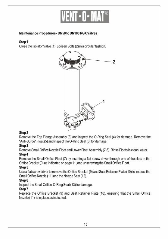
Maintenance Procedures - DN50 to DN100 RGX Valves
Step 1Close the Isolator Valve (1). Loosen Bolts (2) in a circular fashion.
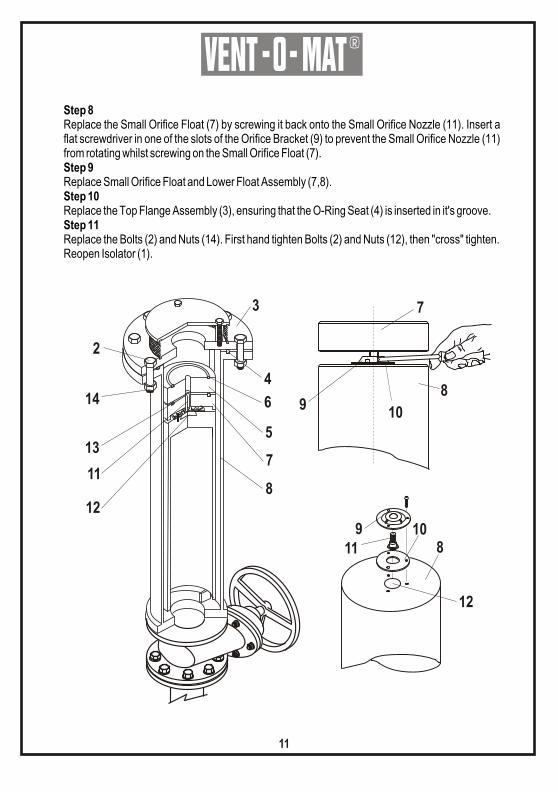
Step 2Remove the Top Flange Assembly (3) and inspect the O-Ring Seal (4) for damage. Remove the "Anti-Surge" Float (5) and inspect the O-Ring Seat (6) for damage.Step 3Remove Small Orifice Nozzle Float and Lower Float Assembly (7,8). Rinse Floats in clean water.Step 4Remove the Small Orifice Float (7) by inserting a flat screw driver through one of the slots in the Orifice Bracket (9) as indicated on page 11, and unscrewing the Small Orifice Float.Step 5Use a flat screwdriver to remove the Orifice Bracket (9) and Seat Retainer Plate (10) to inspect the Small Orifice Nozzle (11) and the Nozzle Seat (12).Step 6Inspect the Small Orifice O-Ring Seat (13) for damage.Step 7Replace the Orifice Bracket (9) and Seat Retainer Plate (10), ensuring that the Small Orifice Nozzle (11) is in place as indicated.
1
2
10
R
Step 8Replace the Small Orifice Float (7) by screwing it back onto the Small Orifice Nozzle (11). Insert a flat screwdriver in one of the slots of the Orifice Bracket (9) to prevent the Small Orifice Nozzle (11) from rotating whilst screwing on the Small Orifice Float (7).Step 9Replace Small Orifice Float and Lower Float Assembly (7,8).Step 10Replace the Top Flange Assembly (3), ensuring that the O-Ring Seat (4) is inserted in it's groove.Step 11Replace the Bolts (2) and Nuts (14). First hand tighten Bolts (2) and Nuts (12), then "cross" tighten. Reopen Isolator (1).
3
4
6
5
7
812
11
13
14
2
8
109
7
9 108
12
11
11
R
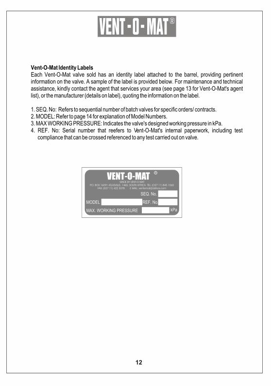
Vent-O-Mat Identity LabelsEach Vent-O-Mat valve sold has an identity label attached to the barrel, providing pertinent information on the valve. A sample of the label is provided below. For maintenance and technical assistance, kindly contact the agent that services your area (see page 13 for Vent-O-Mat's agent list), or the manufacturer (details on label), quoting the information on the label.
1. SEQ. No: Refers to sequential number of batch valves for specific orders/ contracts.2. MODEL: Refer to page 14 for explanation of Model Numbers.3. MAX WORKING PRESSURE: Indicates the valve's designed working pressure in kPa.4. REF. No: Serial number that reefers to Vent-O-Mat's internal paperwork, including test
compliance that can be crossed referenced to any test carried out on valve.
VENT-O-MATR
MADE BY VENT-O-MATP.O. BOX 16091 ATLASVILLE, 1465, SOUTH AFRICA TEL: (O27 11) 845 1060
FAX: (027 11) 422 3078 E MAIL: [email protected]
MODEL
MAX. WORKING PRESSURE
REF. No.
SEQ. No.
kPa
12

R
VENT-O-MAT LOCAL AND INTERNATIONAL AGENTS
Vent-O-Mat is represented through a network of dedicated agents. Kindly contact the agent in your region/ country for technical and sales assistance.
South Africa - Gauteng, Free State & BotswanaIndependent Valve Marketing Tel: (011) 918 4057 Fax: (011) 894 5237
South Africa - Kwa Zulu NatalAmanzi Valves Tel: (031) 903 6448 Fax: (031) 903 6366
South Africa - Western, Northern & Eastern CapeVac Cent Services Tel: (021) 905 2520 Fax: (021) 905 1429
NamibiaValco Services Tel: (+264) 61 161199 Fax: (+264) 61 263114
EuropeBopp & Reuther Tel: (+49) 621 749 164 Fax: (+49) 621 749 1486
KuwaitKuwait Maritime & Mercantile Tel: (+65) 2434752 Fax: (+65) 2441486
United Arab EmiratesAbu Dhabi Maritime & Mercantile Tel: (+71) 2 273 131 Fax: (+71) 2 273 587
United States of America & CanadaInternational Valve Marketing Tel: (+1) 815 439 0588 Fax: (+1) 815 439 2477
Australia, Philippines, New Zealand, Indonesia & MalaysiaVent-O-Mat Australia Tel: (+61) 2 9624 3755 Fax: (+61) 2 9624 5561
Africa, Asia, Middle East, South & Central AmericaVent-O-Mat Marketing Tel: (027 11) 748 0317 Fax: (027 11) 422 3078World Wide Web: http://www.ventomat.com E Mail: [email protected]
EgyptBuisiness International Group Tel. (202) 401 8896 Fax. (202) 401 5024
13
R
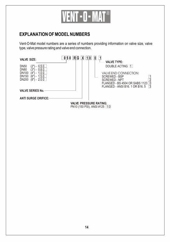
EXPLANATION OF MODEL NUMBERS
Vent-O-Mat model numbers are a series of numbers providing information on valve size, valve type, valve pressure rating and valve end connection.
VALVE SERIES No.
ANTI SURGE ORIFICE:
0 5 0 R G X 1 0 0 1VALVE SIZE:
DN50 (2") - 0 5 0DN80 (3") - 0 8 0DN100 (4") - 1 0 0DN150 (6") - 1 5 0DN200 (8") - 2 0 0
VALVE TYPE:
DOUBLE ACTING 1
VALVE END CONNECTION:SCREWED - BSP 1SCREWED - NPT 2FLANGED - BS 4504 OR SABS 1123 0FLANGED - ANSI B16. 1 OR B16. 5 3
VALVE PRESSURE RATING:PN10 (150 PSI), ANSI #125 1 0
14
R
SEWAGE AIR VALVE SIZING AND POSITIONING
The presence of air/gas in a sewer main in service or in the process of being filled is well known to be the cause of serious problems such as delay in filling, throttling and reduction in discharge capacities, risk of surge and corrosion.
The indiscriminate selection and positioning of double acting sewage air valves, without thorough evaluation of the system characteristics and dynamics will not solve the problem of air/gas in the main but can and will lead to the aggravation of phenomena associated with it's presence as well as introduce other destructive phenomena.
Air valve selection and positioning is a complex exercise because of the unpredictable nature of air/gas as it is influenced by many factors such as pressure, temperature, pipeline velocities etc., and it in turn influences the pipeline dynamics dramatically, making it difficult to quantify.
This section of the document provides the engineer with a guideline of where to position and how to size Vent-O-Mat sewage air valves to ensure the maximum performance and protection is gained from every valve installation. Reference should also be made to Vent-O-Mat's other publications and Vent-O-Mat's computer sizing disc for a more comprehensive guide on air valve sizing and positioning.
Positioning of Sewage Air ValvesSewage air valves are positioned primarily on peak points to discharge air/gas during initial filling and to draw air into the pipeline under drainage conditions. There are however, a number of other locations where sewage air valves need to be installed to ensure effective pipeline operation and protection against phenomena such as surge. The table below provides a quick check reference on where to position sewage air valves.
Recommended Air Valve Locations
On apex points relative to the hydraulic gradeline.5 metres below the apex points formed by the intersection of the hydraulic gradeline.Negative breaks - increase in downward slope or decrease in upward slope.Long horizontal sections - every 600 metres.Long ascending sections - every 600 metres.Long descending sections - every 600 metres.Pump discharge - subsequent to a pump non return valve.Blank ends - where a pipeline is terminated by a blank flange or a valve.
15
R
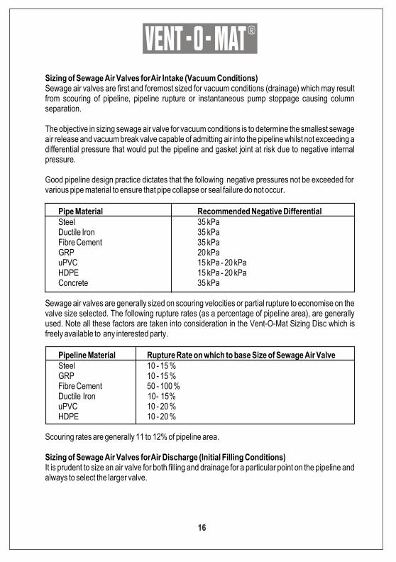
Sizing of Sewage Air Valves for Air Intake (Vacuum Conditions)Sewage air valves are first and foremost sized for vacuum conditions (drainage) which may result from scouring of pipeline, pipeline rupture or instantaneous pump stoppage causing column separation.
The objective in sizing sewage air valve for vacuum conditions is to determine the smallest sewage air release and vacuum break valve capable of admitting air into the pipeline whilst not exceeding a differential pressure that would put the pipeline and gasket joint at risk due to negative internal pressure.
Good pipeline design practice dictates that the following negative pressures not be exceeded for various pipe material to ensure that pipe collapse or seal failure do not occur.
Pipe Material Recommended Negative DifferentialSteel 35 kPaDuctile Iron 35 kPaFibre Cement 35 kPaGRP 20 kPauPVC 15 kPa - 20 kPaHDPE 15 kPa - 20 kPaConcrete 35 kPa
Sewage air valves are generally sized on scouring velocities or partial rupture to economise on the valve size selected. The following rupture rates (as a percentage of pipeline area), are generally used. Note all these factors are taken into consideration in the Vent-O-Mat Sizing Disc which is freely available to any interested party.
Pipeline Material Rupture Rate on which to base Size of Sewage Air ValveSteel 10 - 15 %GRP 10 - 15 %Fibre Cement 50 - 100 %Ductile Iron 10 - 15 %uPVC 10 - 20 %HDPE 10 - 20 %
Scouring rates are generally 11 to 12% of pipeline area.
Sizing of Sewage Air Valves for Air Discharge (Initial Filling Conditions)It is prudent to size an air valve for both filling and drainage for a particular point on the pipeline and always to select the larger valve.
16
R
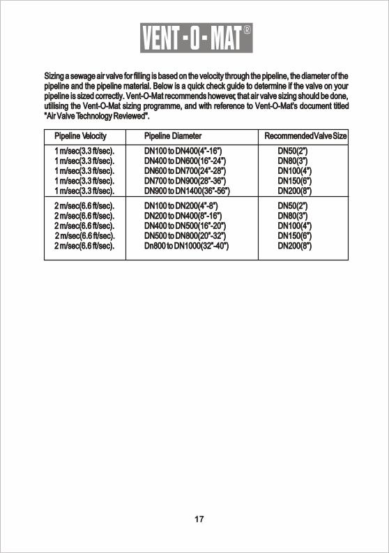
Sizing a sewage air valve for filling is based on the velocity through the pipeline, the diameter of the pipeline and the pipeline material. Below is a quick check guide to determine if the valve on your pipeline is sized correctly. Vent-O-Mat recommends however, that air valve sizing should be done, utilising the Vent-O-Mat sizing programme, and with reference to Vent-O-Mat's document titled "Air Valve Technology Reviewed".
Pipeline Velocity Pipeline Diameter Recommended Valve Size
1 m/sec(3.3 ft/sec). DN100 to DN400(4”-16”) DN50(2”)1 m/sec(3.3 ft/sec). DN400 to DN600(16”-24”) DN80(3”)1 m/sec(3.3 ft/sec). DN600 to DN700(24”-28”) DN100(4”)1 m/sec(3.3 ft/sec). DN700 to DN900(28”-36”) DN150(6”)1 m/sec(3.3 ft/sec). DN900 to DN1400(36”-56”) DN200(8”)
2 m/sec(6.6 ft/sec). DN100 to DN200(4”-8”) DN50(2”)2 m/sec(6.6 ft/sec). DN200 to DN400(8”-16”) DN80(3”)2 m/sec(6.6 ft/sec). DN400 to DN500(16”-20”) DN100(4”)2 m/sec(6.6 ft/sec). DN500 to DN800(20”-32”) DN150(6”)2 m/sec(6.6 ft/sec). Dn800 to DN1000(32”-40”) DN200(8”)
17
R
TECHNICAL FEATURES & FINANCIAL BENEFITS
The criteria for assessing the merits of any form of pipeline equipment are capital costs and operating and maintenance requirements. It is likely if all the below are taken into account, Vent-O-Mat valves will be seen as a cheap, reliable and efficient form of pipeline protection.
Vacuum ProtectionAll Vent-O-Mat valves have large orifice diameters equal to the nominal size of the valve i.e., a DN200 valve has a 200mm orifice. This ensures the least possible resistance to the intake of air and consequently the least possible negative pressure within a draining pipeline.
Discharge PerformanceThe Vent-O-Mat valve design is not limited by the velocity within the pipeline and the differential across the large orifice as conventional air valves are. This ensures the effective removal of all air/gas from a filling pipeline whilst eliminating the possibilities of surge on closure of the large orifice.
ServiceabilityThe Vent-O-Mat valve is virtually maintenance free, but facilitates extreme ease of service and maintenance in the rare instances when required. Components are in corrosion free materials to allow problem free disassembly and reassembly even after years of operation. All maintenance spares are replaceable without special tools or skills.
PerformanceVent-O-Mat series RGX has been designed and developed to provide the optimum usable and safe performance relative to all functions. Selection data has bee substantiated through the council of Scientific and Industrial Research - South Africa and other testing and can be confidently referenced.
Surge ProtectionVent-O-Mat offers a cost effective and efficient solution to destructive phenomena such as surge as all valves are supplied as standard, with an integral "Anti-Surge" surge alleviation mechanism. This device only operates in instances such as rapid filling or column separation to effectively and efficiently eliminate surge, very much like an air bag in a motor vehicle in that it only operates in emergencies.
18
R
Financial BenefitsThe "Anti-Surge" mechanism together with other features of the Vent-O-Mat design provides a number of financial benefits some of which are:
Reduction in Size or Total Elimination of Traditional Surge Protection DevicesThe valve acts both as an effective double acting air valve and as a cost effective surge alleviation mechanism. Accommodating the Vent-O-Mat series RGX air valve in total surge protection strategy renders total protection to a pipeline at a fraction of the cost of any conventional method.
Shortening of Operational ProceduresLengthy operational procedures can be dramatically shortened when utilising Vent-O-Mat air valves with out the risk of pipeline collapse, premature closure or water hammer. This allows for major time saving.
Cost Saving on Overspecified PipeVery many design engineers overspecify on pipe thickness to prevent unforeseen pipeline damage. This is unnecessary when utilising Vent-O-Mat air valves as it efficiently manages air within the pipeline therefore greatly minimising the possibility of unforeseen accidents.
Increase of Flow Through Existing InfrastructureMany pipeline operate very inefficiently because of restriction created by air/gas that is not released effectively by air valves. Vent-O-Mat valves are designed to discharge all air/gas in a pipeline regardless of flow velocities, without the inducement of water hammer and other destructive phenomena associated with kinetic air valves. This feature allows for the increase of flow of up to 30% through existing infrastructure, by the mere replacement of conventional air valves with the Vent-O-Mat design.
19
R
SHIPPING & STORAGE
ShippingVent-O-Mat valves are generally shipped by the factory or it's agents in well constructed wooden crates or cases, with the content, destination and factory (or agent's) details clearly marked by a label on at least two sides of the crate or case. Valves are carefully packed to ensure that no damage occurs during transit.
StorageIt is recommended that the valves be stored in a cool area if not to be used immediately.
20
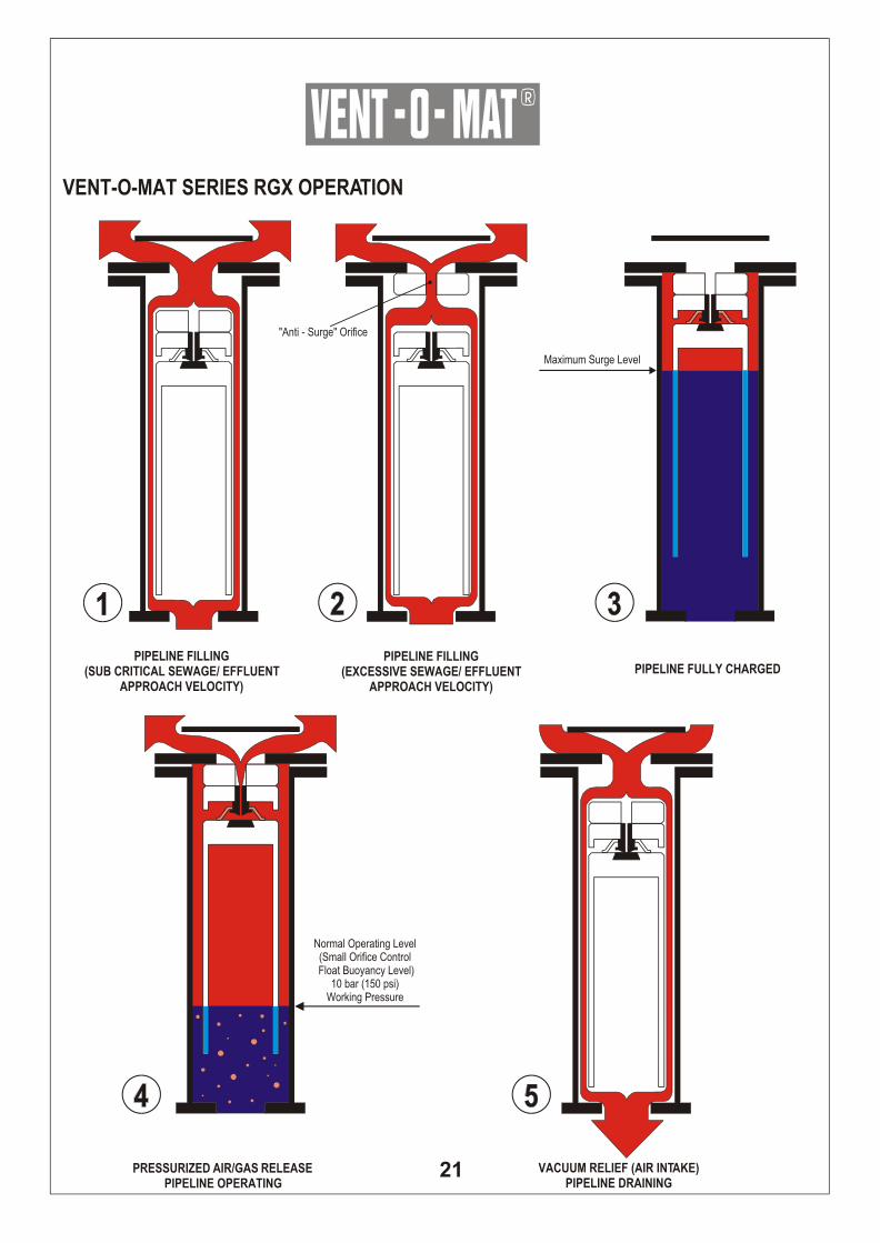
VENT-O-MAT SERIES RGX OPERATION
PIPELINE FILLING(SUB CRITICAL SEWAGE/ EFFLUENT
APPROACH VELOCITY)
PIPELINE FILLING(EXCESSIVE SEWAGE/ EFFLUENT
APPROACH VELOCITY)
PIPELINE FULLY CHARGED
PRESSURIZED AIR/GAS RELEASEPIPELINE OPERATING
VACUUM RELIEF (AIR INTAKE)PIPELINE DRAINING
Normal Operating Level(Small Orifice Control
Float Buoyancy Level)10 bar (150 psi)
Working Pressure
Maximum Surge Level
"Anti - Surge" Orifice
R
21
VENT-O-MAT SERIES RGX OPERATION
A) VENTING OF A FILLING PIPELINE:The operation of a conventional sewage air release valve is such that fast approaching sewage/effluent is almost instantaneously halted by the valve's closure. Consequently surge pressures of potentially damaging proportions can be generated in a pipeline system, even at normal filling rates. In addition to venting through the Large Orifice when sewage/effluent approach velocities are sub critical, the Vent -O- Mat series RGX sewage air release valves feature an automatic "Anti - Surge" Orifice device that serves to decelerate sewage/effluent approaching at excessive speed, thereby limiting pressure rise in the pipeline.
B) SURGE ALLEVIATION - PIPELINE PRESSURIZED:In instances where a pipeline experiences liquid column separation due to pump stoppage, high surge pressures can be generated when the separated column rejoins. The Vent -O- Mat series RGX takes in air through the unobstructed large orifice when column separation occurs, but controls the discharge of air/gas through the "Anti-Surge" Orifice as the separated column commences to rejoin. The rejoining impact velocity is thereby sufficiently reduced to prevent an unacceptably high surge pressure in the system. In the same way the series RGX valve prevents high surge pressures resulting from liquid oscillation in a pipeline.
1. PIPELINE FILLING (SUB CRITICAL SEWAGE/ EFFLUENT APPROACH VELOCITY)Air/gas flows through the annular area around the control float assembly and to atmosphere through the large orifice.
2. PIPELINE FILLING (EXCESSIVE SEWAGE/ EFFLUENT APPROACH VELOCITY)In reaction to an increase in air/gas flow, the "Anti - Surge" float closes the large orifice and air/gas is forced through the "Anti - Surge" Orifice resulting in a deceleration of the approaching liquid due to the resistance of rising air/gas pressure in the valve.
Attention is drawn to Pre Notes (A) and (B) above.
3. PIPELINE FULLY CHARGEDSewage/effluent has entered the the valve chamber and buoyed the floats to close both the large and the small orifice. The design's compression/volume relationship prevents the media from ever exceeding the maximum surge level indicated in diagram 3. The resultant sewage/effluent free area protects against the fouling of the orifice seals by solids or high viscous substances - for this reason NO FLUSHING CONNECTIONS ARE NECESSARY.
4. PRESSURIZED AIR/ GAS RELEASE - PIPELINE OPERATINGThe volume of disentrained air/gas increases in the valve and displaces the sewage/effluent to the lower, normal operating level (small orifice control float buoyancy level). Any additional lowering of the sewage/effluent level, as would occur when more air/gas enters the valve, will result in the control float dropping away from the small orifice through which pressurized air/gas is then being discharged to atmosphere. The control float will close the small orifice when sufficient air/gas has been released to restore the sewage/effluent to the normal opperating level.The considerable sewage/effluent free area obviates the possibility of leaks that could otherwise be caused by solids entering the sealing areas - for this reason NO FLUSHING CONNECTIONS ARE NECESSARY.
5. VACUUM RELIEF (AIR INTAKE) - PIPELINE DRAINING When the internal pipeline pressure reduces to atmosphere the "Anti - Surge" mechanism and control float assembly drops, opens the large orifice and allows the pipeline to take in air to displace the draining media so as to prevent undesirable low negative pressure*.
The hollow, smooth side float design discourages adherence of solids and viscous substances which, therefore, tend to withdraw from the valve into the pipeline when draining occurs - for this reason NO FLUSHING CONNECTIONS ARE NECESSARY.
*NOTE: Negative pressure values are dependant on valve size selection.
PRE NOTES:
22
R
R
FLANGE ALIGNMENTS
The drilling of the connecting flanges of all Vent-O-Mat valves are done on computerised CNC machines to the relevant ANSI or BS standards, ensuring the highest degree of accuracy at all times.
23
R
MULRIC HYDRO PROJECTS T/A VENT-O-MAT(hereinafter referred to as the 'COMPANY')
STANDARD CONDITIONS OF TENDER AND SALE(Clauses 1 to 21)
1. ACCEPTANCE:Except where specifically agreed to the contrary in writing by the 'Company', orders resulting from the 'Company's' written or
verbal quotations or price lists are subject to the terms and conditions embodied herein.2. CONTRACTUAL LIMITATIONS:
The 'Company's' supply is limited to such equipment, accessories, work and documentation as is specified in its quotations.
3. DRAWINGS AND DATA:All drawings, illustrations, descriptive literature, technical data or particulars of mass and dimension accompanying the'
Company's' quotations must be considered approximate except when specifically certificated.4. TESTS:
The goods will be tested in accordance with the specifications of the 'Company's ' tender and/ or the relevant standard specifications as stated therein.
5. AVAILABILITY:(a) Offers for equipment available ex-stock are subject to such stock remaining unsold at time of order placement.(b) Delivery periods quoted are based on the manufacturing position as at the time of quotation. Whilst every endeavour will be made to maintain such deliveries, no liability shall be accepted by the 'Company'
for delay due to causes beyond fits control.(c) The 'Company' shall only accept liability for late delivery where the 'Company's' liability for such late delivery is not excluded in terms of the foregoing and where the 'Company' has specifically agreed in writing to the payment of a penalty or liquidated damages or damages for such late delivery, in which case the 'Company's' Liability shall be limited to the amount so agreed.
6. DELIVERY:The 'Company' will deliver, where provided for, to a destination named in its quotation at which point the 'Company's' responsibility for the goods will cease.
7. PACKING:Where the 'Company' deems goods vulnerable to damage during transit, the 'Company' reserves the right to pack such goods in suitable protective packaging or crates at the Purchaser's cost. Invoices for packing will be substantiated by a copy of relevant documentation from the packaging contractor.
8. PRICE BASIS:Prices referenced from the 'Company's' valid lists or from the 'Company's' written or verbal quotation exclude packaging and delivery.
9. PAYMENT TERMS:(a) Without exception, payment for all goods and services shall be received by the 'Company' not later than 30 (THIRTY) days subsequent to the date of statement Interest at prime lending rate + 2% will be
charged on all overdue amounts.(b) Where the 'Company' has quoted delivery point as Ex-works, delivery shall be deemed to have been effected when the goods are ready for collection, at which time, the Purchaser shall be advised and an invoice will begenerated.Payment for Ex-works goods shall be due within the requisite period in accordance with the 'Company's' payment terms, starting from the date on which order completion advice was issued to the Purchaser. Failure or delay by the Purchaser or Purchaser's sub contractor to effect collection of completed goods shall not relieve the Purchaser from the contractual obligation to remit payment within 30 days from statement date.
10. DISCOUNT:(a) It is the NONNEGOTIABLE policy of the 'Company' that, where provided for, discount is allowed only where full and final SETTLEMENT is received within 30 (THIRTY) days from date of statement.
(b) The 'Company's' delivery note/invoice reflects the date by which payment must be received to qualify for discount, therefore late receipt or non-receipt of statements will not constitute acceptable reason for payment delays.
25
R
(c) Late payments which reflect arbitrary discount deductions will be received without prejudice to the 'Company's' right to full and final payment.1 1. TITLE:Ownership of all goods supplied by the 'Company' will not pass to the purchaser or any other party until paid for in full and until such time, the 'Company' shall be entitled to repossess the goods whether affixed to immovable property or not. All such goods shall be deemed to be removable property and severable from immovable property.12. TENDER/ QUOTATION VALIDITY:
(a) Written or verbal quotations will be held valid for a maximum of 30 (THIRTY) days unless contradicted in writing by the 'Company' .(b) Prices are quoted by the 'Company' in good faith based on the ruling costs of material, labour, transport and, if applicable, insurance, sureties and retention monies, as well as statutory government taxes. levies, duties and surcharges Severely adverse changes and/or additions to any of these costs components which are contributory in the calculation of a price or prices quoted by the 'Company' will be for the purchasers account.
13. PRICE VARIATION: The Purchaser undertakes to refund to the 'Company' any extra costs Incurred by the 'Company' as a result of the
Purchaser's Instruction or lack of instructions and for the purpose of this paragraph extra cost shall mean any amount which the 'Company' becomes liable to pay, whether in wages, for materials or otherwise howsoever in respect of the work which the 'Company' would not have been liable to pay but for the Purchaser's action or default In the event of dispute on the amount of the extra cost, the decision of a mutually agreed upon arbitrator at Johannesburg, shall be final and binding.
14. CANCELLATION:(a) Order cancellation or variation will not be considered without the written consent of the 'Company'; and(b)In the case of equipment being or having been manufactured specifically for an order, the purchaser will be liable to pay proportion of the price according to the stage of completion of the equipment ordered.
15. RETURNS FOR CREDIT:Acceptance of goods returned will be entirely at the discretion of the 'Company' and subject to a minimum restocking charge equal to 15% of the gross invoiced value of such returned goods.
16. ESCALATION:Where the sum of the quotation validity period and delivery period is in excess of 90 (NINETY) days, prices for goods or services quoted by the 'Company' are subject to escalation in accordance with the relevant SEIFSA indices for material, labour and transport.
17. GUARANTEE:(a) The 'Company' guarantees that the goods supplied will conform to specification an to any requirements
specifically accepted by the 'Company 'in writing in regard to each order but, except as aforesaid the 'Company's' gives no warranty, express or implied, of material workmanship or fitness of goods for any particular purpose whether such purpose be known to us or not. In the event of the goods proving to be not in accordance with the specifications or requirements aforesaid, or should defects under proper use appear in the goods within a period of 12 (TWELVE) calendar months after the goods have been delivered, caused solely by faulty design, materials or workmanship, we shall, if requested to do so within a reasonable time, but not later than 18 (EIGHTEEN) calendar months from date of delivery repair such goods, or at our option replace goods or the defective parts thereof, free of charge by supplying other goods or replacement parts at the initial place of delivery which do comply with the specifications or requirements aforesaid and/or which are free of the defects complained of.
(b) It is a condition of this guarantee:(i) that any defective parts are returned to the 'Company's' works at the Purchaser's expense; and(Ii) in respect of parts or components not of the 'Company's' manufacture, the 'Company's' guarantee shall be limited to the guarantee, if any, which we may have received from the suppler of such parts or
components in respect thereof so that the 'Company's' liability in terms of such guarantee shall be no greater than the 'Company's' liability in terms of the 'Company's' own guarantee as set out in this clause
(Iii) the 'Company' shall be given reasonable time and opportunity to comply with the terms of the guarantee before you call upon the 'Company' to pay any sums in respect of liquidated damages;
and(iv) save as provided in this clause, the 'Company' shall be under no liability, whether in contract, delict or otherwise in respect of defects in goods delivered, or for any injury, damage or loss resulting from defect or from any work done in connection therewith.
26
R
1 8. PATENTS:The 'Company' will indemnify the Purchaser against any claim of infringement of Letters Patent or Registered Design (published at the date of the Contract) by the use or sale of any article or material supplied by the 'Company' to the Purchaser and against all costs and damages which the Purchaser may incur in any such action. Provided always that this indemnity shall apply to an infringement which is due to the 'Company' having followed a design or instruction furnished or given by the Purchaser or to the use of such articles or material in a manner or for a purpose or in a foreign country not specified by or disclosed to the 'Company', provided that this iindemnity is conditional on the Purchaser giving the 'Company' the earliest possible notice in writing of any claim being made or action threatened or brought against the Purchaser and on the Purchaser permitting the 'Company' at the 'Company's' own expenses to conduct any litigation that may ensue and all negotiations for a settlement of the claim. The Purchaser on their part warrant that any design or instruction furnished or given by the Purchaser shall not be such as will cause the 'Company' to infringe any Lenders Patent, Registered Design or Trade Mark in the execution of the Purchaser's order. 19. LIMITED LIABILITY:The 'Company' shall not be liable for any Incidental or consequential loss, damages or expense arising directly or indirectly from the use of any goods supplied, nor shall liability be accepted for any labour or other expenses incurred. The 'Company's' liability is limited solely to the terms of its guarantee. 20. LEGAL CONSTRUCTION:Contracts entered into with the 'Company' shall be interpreted and construed in accordance with the laws of the Republic of South Africa whose courts shall have jurisdiction in respect of any dispute whatsoever. 21. LEGAL JURISDICTION:In terms of Section 45 of the Magistrates Court Act of 1944 the Purchaser consents to the jurisdiction of any Magistrates Court by virtue of Section 20 of the said Act, notwithstanding that any Calm against the Purchaser may exceed the jurisdiction of such Magistrate s Court It is recorded that the 'Company' is not bound hereby and shall be entitled to institute any proceedings against the Purchaser out of any other Court of competent jurisdiction .
WARRANTY
(a) The 'Company' guarantees that the goods supplied will conform to specifications and to any requirements specifically accepted by the 'Company' in writing in regard to each order but, except as aforesaid, the 'Company' gives no warranty, express or implied, of the material workmanship or fitness of goods for any particular purpose whether such purpose is known to us or not. In accordance with the specifications or requirements aforesaid, or should defects under proper use appear in the goods within a period of 12 (TWELVE) calendar months after the goods have been delivered, caused solely by faulty design, materials or workmanship, we shall, if requested to do so within a reasonable time, but not later than 18 (EIGHTEEN) calendar months, from date of delivery, repair such goods or the defective parts thereof, free of charge by supplying other goods or replacement parts at the initial place of delivery which do comply with specifications or requirements aforesaid and/or which are free of the defects complained of.(b) It is a condition of this guarantee:
(I) that any defective parts are returned to the 'Company's' works at the purchaser's expenses and;(Ii) in respect of parts or components not of the 'Company's' manufacture, the 'Company's' guarantee shall be limited to the guarantee, if any which we may have received from the supplier of such parts or components iin respect thereof so that the 'Company's' liability in terms of such guarantee shall be no greater than the 'Company's' liability in terms of the 'Company's' own guarantee as set out in this clause;(iii) the 'Company' shall be given reasonable time and opportunity to comply with the terms of the guarantee before you call on the 'Company' to pay any sums in respect of the liquidated damages and;(iv) save as provided in the clause, the 'Company' shall be under no liability, whether in contract, delict or otherwise in respect of defects in goods delivered, or for any injury, damage or loss resulting from defect or from any work done in connection therewith.
27