Embed Size (px)
Citation preview
High Voltage • High Current • High Power Test Systems and Components
PHENIX TECHNOLOGIES • Accident, Maryland USA • www.phenixtech.com • +1.301.746.8118
PORTABLE PRODUCTSfor Field Testing
TECHNOLOGIES
PHENIX
R
CIRCUIT BREAKER
VACUUMINTERRUPTER
CABLE
G
GENERATOR GIS
SWITCHGEAR
INSULATION
MATERIALS
MOTOR PORTABLE PROTECTIVE
EQUIPMENT
RECLOSER TRANSFORMER
TECHNOLOGIES
PHENIX
R
www.phenixtech.com
2 PORTABLE PRODUCTS FOR FIELD TESTING
INTRODUCTION
PHENIX Technologies is a manufacturer of high voltage, high current, high power test systems and components. We have been in business since 1975. Our manufacturing facility is located in Accident, Maryland, USA with additional sales offices located in Basel, Switzerland and Taipei, Taiwan. Additionally, we have sales representative organizations across the U.S. and in over 75 countries.
Our state-of-the-art products have been delivered around the world providing quality assurance testing solutions to:
• Electrical Utilities
• Equipment Manufacturers
• Motor Manufacturers and Repair Industry
• Transformer Manufacturers and Repair Industry
• Cable Manufacturers and Service Contractors
• Personal Protective Equipment Test Laboratories
• Field Service Organizations
• High Voltage Test Laboratories
• Quality Control Areas
PHENIX Technologies offers a full line of standard-design products as well as the expertise to design and build custom test systems.
Our products are divided into two main categories:
Power Products such as AC Dielectric Test Systems, Resonance Test Systems, Transformer Test Systems, Motor Test Systems, and custom made testing solutions
Standard Portable Products which are summarized in this brochure
GENERAL INFORMATION ON HIGH VOLTAGE TESTING
When we are ready to test in a High Voltage environment, general safety precautions should be taken into account as Hipot testers are capable of providing POTENTIALLY LETHAL VOLTAGES!
Improper operation or test practices may result in injury or death to the operator or surrounding personnel.
The operation of High Voltage test equipment should only be performed by personnel familiar with HIGH VOLTAGE testing and safety procedures. The operator of this equipment must be aware of all hazards associated with High Voltage testing. The operator is responsible for himself and others in close proximity of the testing area.
Some General Safety Practices for working with High Voltage test equipment have been listed below for your reference.
• Become familiar with your instrument before performing an actual test.
• Know your work area, check that all circuits are de-energized and locked out.
• Never work alone; always work with another qualified worker.
• Mark off entire work area with barriers and warning tape.
• Make all personnel aware of your testing activities.
• Be aware of dangerous conditions that may arise from energizing a test specimen.
• Never modify test equipment; modifications to equipment could introduce an unknown hazard or hinder a designed-in safety feature.
• DO NOT operate damaged equipment. Remove power, and do not use the equipment until safe operation can be verified by service-trained personnel.
PHENIX Technologies, Inc. assumes no liability for unsafe or improper useof test equipment.
PORTABLE PRODUCTS for FIELD TESTING
PHENIX Technologies offers a wide variety of Portable
Products (also referred to as Standard Products) which are
designed to be utilized for mobile or field testing.
PHENIX Portable Products are durable, easy to transport and
set up, and featureuser-friendly design interfaces.
PAGEINTRODUCTION TO PHENIX TECHNOLOGIES .................................2GENERAL INFORMATION ON HIGH VOLTAGE TESTING ..............................2TERMINOLOGY ......................................3 AC DIELECTRIC TEST SYSTEMS
• Field and Lab AC Hipots, 6CP/6CB Series (15-200 kV) .............4 • Aerial Lift, Elevated Platform, Insulated Boom AC Hipots, BK Series (36-300 kV) ......................5 • AC Hipots for Vacuum Interrupters (40-60 kV) ....................6 • Liquid Dielectric, LD Series (60-100 kV) .................. 6-7 • AC Hipots (5-15 kV) ........................8DC DIELECTRIC TEST SYSTEMS – DC HIPOTS (40-200 kV) ......................9 UNDERGROUND CABLE NETWORK/ SUBSTATION TEST EQUIPMENT (Ammeter Clear, Safety Spark Gap, Tracing Current Transmitter, Pick Method, Galvanometer) .................. 10 AC/DC HIPOT/MEGOHMMETERS and INSULATION ANALYzERS .....11-12HIGH CURRENT TEST SETS, HC Series (1000-5000 A) ................. 13TRANSFORMER TURNS RATIO TESTERS, WINDING RESISTANCE TESTER ........ 14 MICRO-OHM METERS (10-200 A) ....... 15GROUND JUMPER TESTER ................... 16EARTH RESISTANCE TESTERS ............... 16 AC/DC KILOVOLTMETERS, KVM Series (50-300 kV) .................. 17VARIABLE VOLTAGE POWER SUPPLY ............................... 18CORONA DETECTOR ........................... 18GROUND and DISCHARGE STICKS ....... 19 GUARD and NON-GUARD MEASUREMENT .............................. 20
Specifications are subject to change without notice.
TECHNOLOGIES
PHENIX
R
+1.301.746.8118
PORTABLE PRODUCTS FOR FIELD TESTING 3
TERMINOLOGY
The following terms relate to testing applications in the Electrical Laboratory or temporary Laboratory Set-up and in Test Stations.
High Voltage (HV): • Voltages exceeding 1000 V rms AC or 1000 V DC with current exceeding 2 mA AC or 3 mA DC.
Interlock: • Safety circuit to prevent energizing HV generators until all access doors are closed, and immediately de-energizes HV if door is opened; this function does not necessarily ensure full discharge of stored energy.
Earthing System: • HV test labs with earthing systems reduce potential increases and overvoltages to avoid danger to operators or control and measuring equipment.
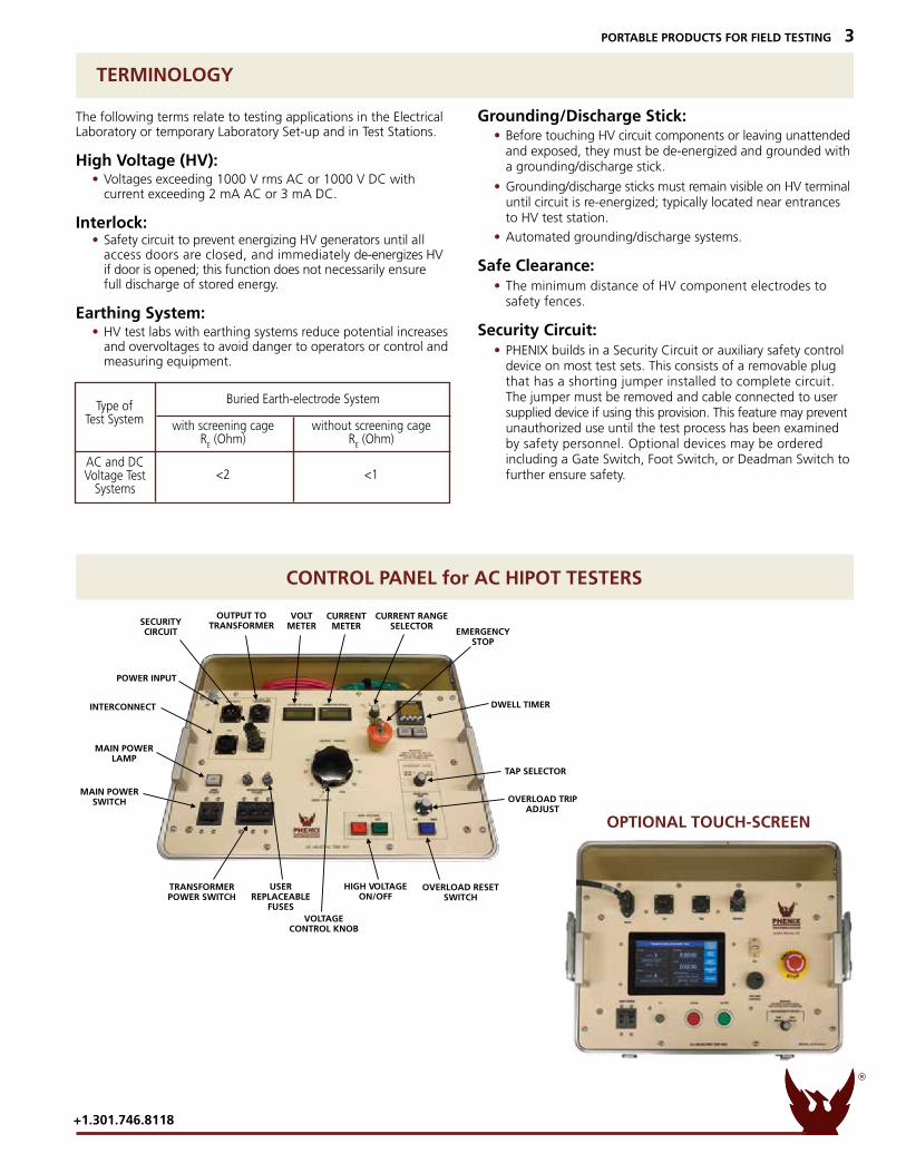
Grounding/Discharge Stick: • Before touching HV circuit components or leaving unattended and exposed, they must be de-energized and grounded with a grounding/discharge stick.
• Grounding/discharge sticks must remain visible on HV terminal until circuit is re-energized; typically located near entrances to HV test station.
• Automated grounding/discharge systems.
Safe Clearance: • The minimum distance of HV component electrodes to safety fences.
Security Circuit: • PHENIX builds in a Security Circuit or auxiliary safety control device on most test sets. This consists of a removable plug that has a shorting jumper installed to complete circuit. The jumper must be removed and cable connected to user supplied device if using this provision. This feature may prevent unauthorized use until the test process has been examined by safety personnel. Optional devices may be ordered including a Gate Switch, Foot Switch, or Deadman Switch to further ensure safety.
Buried Earth-electrode System with screening cage without screening cage R
E (Ohm) R
E (Ohm)
<2 <1
Type ofTest System
AC and DC Voltage Test
Systems
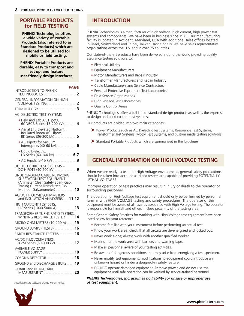
CONTROL PANEL for AC HIPOT TESTERS
OPTIONAL TOUCH-SCREEN
SECURITYCIRCUIT
POWER INPUT
INTERCONNECT
MAIN POWERLAMP
MAIN POWERSWITCH
TRANSFORMERPOWER SWITCH
USERREPLACEABLE
FUSESVOLTAGE
CONTROL KNOB
HIGH VOLTAGEON/OFF
OVERLOAD RESETSWITCH
OUTPUT TOTRANSFORMER
VOLTMETER
CURRENTMETER
EMERGENCYSTOP
DWELL TIMER
TAP SELECTOR
OVERLOAD TRIPADJUST
CURRENT RANGESELECTOR
TECHNOLOGIES
PHENIX
R
www.phenixtech.com
4 PORTABLE PRODUCTS FOR FIELD TESTING
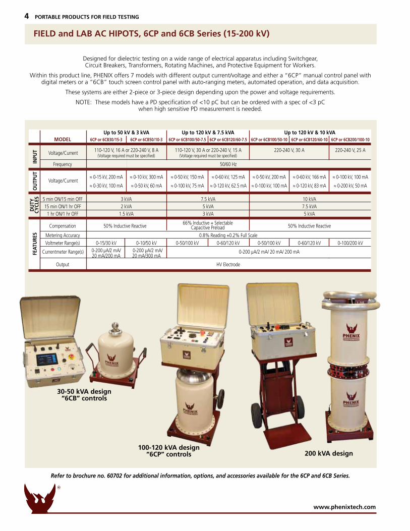
FIELD and LAB AC HIPOTS, 6CP and 6CB Series (15-200 kV)
Refer to brochure no. 60702 for additional information, options, and accessories available for the 6CP and 6CB Series.
Designed for dielectric testing on a wide range of electrical apparatus including Switchgear, Circuit Breakers, Transformers, Rotating Machines, and Protective Equipment for Workers.
Within this product line, PHENIX offers 7 models with different output current/voltage and either a “6CP” manual control panel with digital meters or a “6CB” touch screen control panel with auto-ranging meters, automated operation, and data acquisition.
These systems are either 2-piece or 3-piece design depending upon the power and voltage requirements.
NOTE: These models have a PD specification of <10 pC but can be ordered with a spec of <3 pC when high sensitive PD measurement is needed.
30-50 kVA design“6CB” controls
100-120 kVA design “6CP” controls 200 kVA design
66% Inductive + SelectableCapacitive Preload
INPU
TO
UTP
UT
FEAT
URE
SD
UTY
CYCL
ES
Voltage/Current
Voltage/Current
Currentmeter Range(s) 0-200 µA/2 mA/ 20 mA/ 200 mA
MODEL 6CP or 6CB30/15-3 6CP or 6CB50/10-3 6CP or 6CB100/50-7.5 6CP or 6CB120/60-7.5 6CP or 6CB100/50-10 6CP or 6CB120/60-10 6CP or 6CB200/100-10 110-120 V, 16 A or 220-240 V, 8 A 110-120 V, 30 A or 220-240 V, 15 A 220-240 V, 30 A 220-240 V, 25 A (Voltage required must be specified) (Voltage required must be specified) Frequency 50/60 Hz
≈ 0-15 kV, 200 mA ≈ 0-10 kV, 300 mA ≈ 0-50 kV, 150 mA ≈ 0-60 kV, 125 mA ≈ 0-50 kV, 200 mA ≈ 0-60 kV, 166 mA ≈ 0-100 kV, 100 mA
≈ 0-30 kV, 100 mA ≈ 0-50 kV, 60 mA ≈ 0-100 kV, 75 mA ≈ 0-120 kV, 62.5 mA ≈ 0-100 kV, 100 mA ≈ 0-120 kV, 83 mA ≈ 0-200 kV, 50 mA
5 min ON/15 min OFF 3 kVA 7.5 kVA 10 kVA 15 min ON/1 hr OFF 2 kVA 5 kVA 7.5 kVA 1 hr ON/1 hr OFF 1.5 kVA 3 kVA 5 kVA Compensation 50% Inductive Reactive 50% Inductive Reactive Metering Accuracy 0.8% Reading +0.2% Full Scale
Voltmeter Range(s) 0-15/30 kV 0-10/50 kV 0-50/100 kV 0-60/120 kV 0-50/100 kV 0-60/120 kV 0-100/200 kV 0-200 µA/2 mA/ 0-200 µA/2 mA/ 20 mA/200 mA 20 mA/300 mA
Output HV Electrode
Up to 50 kV & 3 kVA Up to 120 kV & 7.5 kVA Up to 120 kV & 10 kVA
TECHNOLOGIES
PHENIX
R
+1.301.746.8118
PORTABLE PRODUCTS FOR FIELD TESTING 5
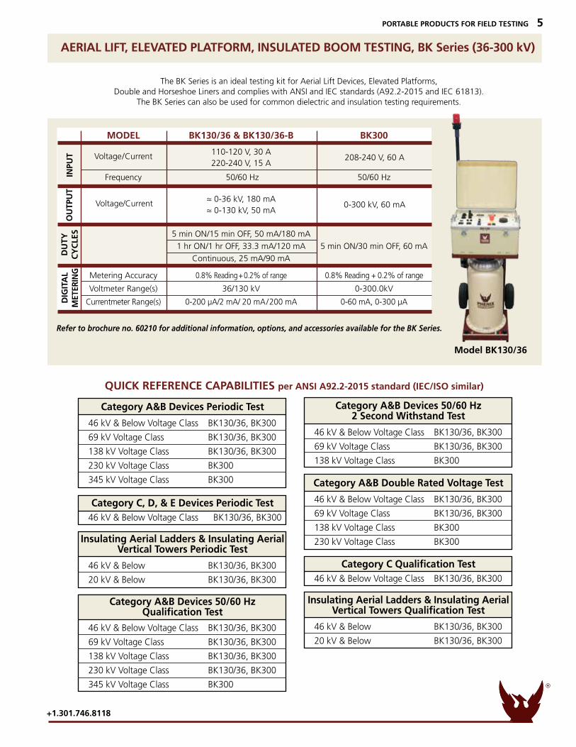
AERIAL LIFT, ELEVATED PLATFORM, INSULATED BOOM TESTING, BK Series (36-300 kV)
The BK Series is an ideal testing kit for Aerial Lift Devices, Elevated Platforms,Double and Horseshoe Liners and complies with ANSI and IEC standards (A92.2-2015 and IEC 61813).
The BK Series can also be used for common dielectric and insulation testing requirements.
Refer to brochure no. 60210 for additional information, options, and accessories available for the BK Series.
Model BK130/36
QUICK REFERENCE CAPABILITIES per ANSI A92.2-2015 standard (IEC/ISO similar)
Category A&B Devices 50/60 Hz 2 Second Withstand Test
46 kV & Below Voltage Class BK130/36, BK300
69 kV Voltage Class BK130/36, BK300
138 kV Voltage Class BK300
Category A&B Double Rated Voltage Test
46 kV & Below Voltage Class BK130/36, BK300
69 kV Voltage Class BK130/36, BK300
138 kV Voltage Class BK300
230 kV Voltage Class BK300
Category C Qualification Test 46 kV & Below Voltage Class BK130/36, BK300 Insulating Aerial Ladders & Insulating Aerial
Vertical Towers Qualification Test
46 kV & Below BK130/36, BK300
20 kV & Below BK130/36, BK300
Category A&B Devices Periodic Test
46 kV & Below Voltage Class BK130/36, BK300
69 kV Voltage Class BK130/36, BK300
138 kV Voltage Class BK130/36, BK300
230 kV Voltage Class BK300
345 kV Voltage Class BK300
Category C, D, & E Devices Periodic Test 46 kV & Below Voltage Class BK130/36, BK300 Insulating Aerial Ladders & Insulating Aerial
Vertical Towers Periodic Test
46 kV & Below BK130/36, BK300
20 kV & Below BK130/36, BK300
Category A&B Devices 50/60 Hz Qualification Test
46 kV & Below Voltage Class BK130/36, BK300
69 kV Voltage Class BK130/36, BK300
138 kV Voltage Class BK130/36, BK300
230 kV Voltage Class BK130/36, BK300
345 kV Voltage Class BK300
MODEL BK130/36 & BK130/36-B BK300
110-120 V, 30 A 220-240 V, 15 A
Frequency 50/60 Hz 50/60 Hz
≈ 0-36 kV, 180 mA ≈ 0-130 kV, 50 mA
5 min ON/15 min OFF, 50 mA/180 mA
1 hr ON/1 hr OFF, 33.3 mA/120 mA 5 min ON/30 min OFF, 60 mA
Continuous, 25 mA/90 mA
Metering Accuracy 0.8% Reading + 0.2% of range 0.8% Reading + 0.2% of range
Voltmeter Range(s) 36/130 kV 0-300.0kV
Currentmeter Range(s) 0-200 µA/2 mA/ 20 mA/200 mA 0-60 mA, 0-300 µA
INPU
TO
UTP
UT
DU
TYC
YC
LES
DIG
ITA
LM
ETER
ING
Voltage/Current
Voltage/Current
208-240 V, 60 A
0-300 kV, 60 mA
TECHNOLOGIES
PHENIX
R
www.phenixtech.com
6 PORTABLE PRODUCTS FOR FIELD TESTING
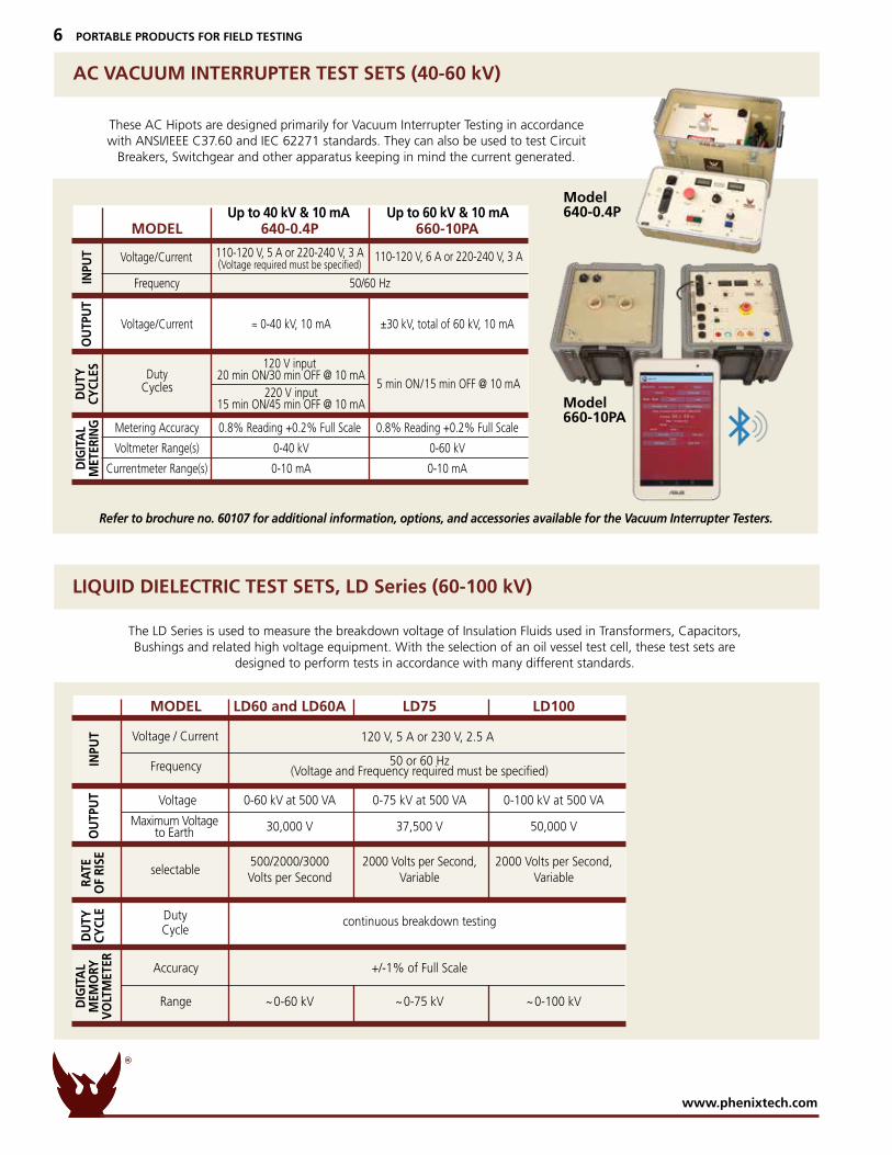
AC VACUUM INTERRUPTER TEST SETS (40-60 kV)
These AC Hipots are designed primarily for Vacuum Interrupter Testing in accordance with ANSI/IEEE C37.60 and IEC 62271 standards. They can also be used to test Circuit
Breakers, Switchgear and other apparatus keeping in mind the current generated.
Refer to brochure no. 60107 for additional information, options, and accessories available for the Vacuum Interrupter Testers.
LIQUID DIELECTRIC TEST SETS, LD Series (60-100 kV)
The LD Series is used to measure the breakdown voltage of Insulation Fluids used in Transformers, Capacitors, Bushings and related high voltage equipment. With the selection of an oil vessel test cell, these test sets are
designed to perform tests in accordance with many different standards.
Model640-0.4P
Model660-10PA
INPU
TO
UTP
UT
RATE
OF
RISE
DU
TYCY
CLE
DIG
ITA
L M
EMO
RYV
OLT
MET
ER
Voltage / Current
selectable
DutyCycle
Frequency
MODEL LD60 and LD60A LD75 LD100
50 or 60 Hz (Voltage and Frequency required must be specified) Voltage 0-60 kV at 500 VA 0-75 kV at 500 VA 0-100 kV at 500 VA 30,000 V 37,500 V 50,000 V
500/2000/3000 2000 Volts per Second, 2000 Volts per Second, Volts per Second Variable Variable
continuous breakdown testing
Accuracy +/-1% of Full Scale Range ~0-60 kV ~0-75 kV ~0-100 kV
Maximum Voltage to Earth
120 V, 5 A or 230 V, 2.5 A
INPU
TO
UTP
UT
DU
TYCY
CLES
DIG
ITA
LM
ETER
ING
Voltage/Current
DutyCycles
110-120 V, 6 A or 220-240 V, 3 A
5 min ON/15 min OFF @ 10 mA
Up to 40 kV & 10 mA Up to 60 kV & 10 mA MODEL 640-0.4P 660-10PA
110-120 V, 5 A or 220-240 V, 3 A (Voltage required must be specified)
Frequency 50/60 Hz
Voltage/Current ≈ 0-40 kV, 10 mA ±30 kV, total of 60 kV, 10 mA
120 V input 20 min ON/30 min OFF @ 10 mA 220 V input 15 min ON/45 min OFF @ 10 mA
Metering Accuracy 0.8% Reading +0.2% Full Scale 0.8% Reading +0.2% Full Scale
Voltmeter Range(s) 0-40 kV 0-60 kV
Currentmeter Range(s) 0-10 mA 0-10 mA
TECHNOLOGIES
PHENIX
R
+1.301.746.8118
PORTABLE PRODUCTS FOR FIELD TESTING 7
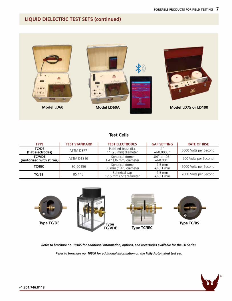
LIQUID DIELECTRIC TEST SETS (continued)
Refer to brochure no. 10105 for additional information, options, and accessories available for the LD Series.
Refer to brochure no. 10800 for additional information on the Fully Automated test set.
TypeTC/VDE Type TC/IEC
Type TC/DE Type TC/BS
TYPE TEST STANDARD TEST ELECTRODES GAP SETTING RATE OF RISE TC/DE Polished brass disc .1” (flat electrodes) 1” (25 mm) diameter +/-0.0005” TC/VDE Spherical dome .04” or .08” (motorized with stirrer) 1.4” (36 mm) diameter +/-0.001” Spherical dome 2.5 mm 36 mm (1.4”) diameter +/-0.1 mm Spherical cap 2.5 mm 12.5 mm (.5”) diameter +/-0.1 mm
ASTM D877
ASTM D1816
IEC 60156
BS 148
TC/IEC
TC/BS
3000 Volts per Second
500 Volts per Second
2000 Volts per Second
2000 Volts per Second
Test Cells
Model LD60 Model LD60A Model LD75 or LD100
TECHNOLOGIES
PHENIX
R
www.phenixtech.com
8 PORTABLE PRODUCTS FOR FIELD TESTING
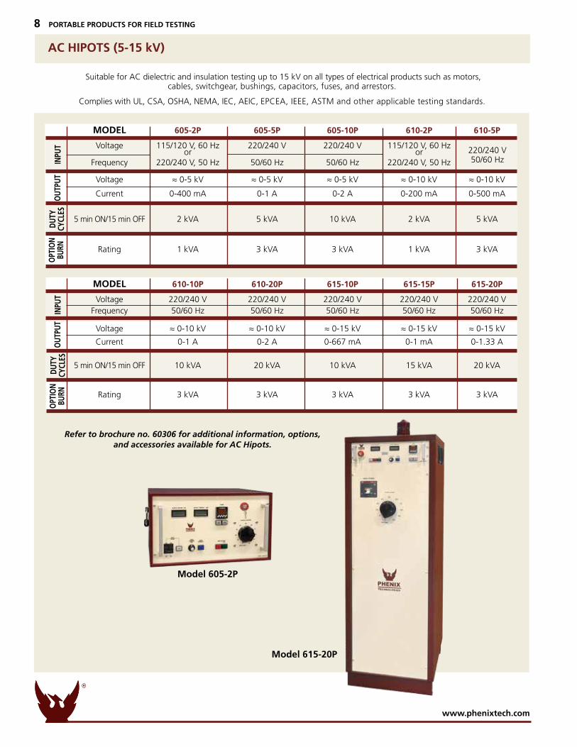
AC HIPOTS (5-15 kV)
Suitable for AC dielectric and insulation testing up to 15 kV on all types of electrical products such as motors, cables, switchgear, bushings, capacitors, fuses, and arrestors.
Complies with UL, CSA, OSHA, NEMA, IEC, AEIC, EPCEA, IEEE, ASTM and other applicable testing standards.
Refer to brochure no. 60306 for additional information, options, and accessories available for AC Hipots.
Model 615-20P
Model 605-2P
OPT
ION
BURN
INPU
TO
UTPU
TDU
TYCY
CLES
MODEL 610-10P 610-20P 615-10P 615-15P 615-20P Voltage 220/240 V 220/240 V 220/240 V 220/240 V 220/240 V Frequency 50/60 Hz 50/60 Hz 50/60 Hz 50/60 Hz 50/60 Hz Voltage ≈ 0-10 kV ≈ 0-10 kV ≈ 0-15 kV ≈ 0-15 kV ≈ 0-15 kV Current 0-1 A 0-2 A 0-667 mA 0-1 mA 0-1.33 A
5 min ON/15 min OFF 10 kVA 20 kVA 10 kVA 15 kVA 20 kVA
Rating 3 kVA 3 kVA 3 kVA 3 kVA 3 kVA
INPU
TO
PTIO
NBU
RNO
UTPU
TDU
TYCY
CLES
MODEL 605-2P 605-5P 605-10P 610-2P 610-5P Voltage 115/120 V, 60 Hz 220/240 V 220/240 V 115/120 V, 60 Hz or or Frequency 220/240 V, 50 Hz 50/60 Hz 50/60 Hz 220/240 V, 50 Hz Voltage ≈ 0-5 kV ≈ 0-5 kV ≈ 0-5 kV ≈ 0-10 kV ≈ 0-10 kV Current 0-400 mA 0-1 A 0-2 A 0-200 mA 0-500 mA
5 min ON/15 min OFF 2 kVA 5 kVA 10 kVA 2 kVA 5 kVA
Rating 1 kVA 3 kVA 3 kVA 1 kVA 3 kVA
220/240 V50/60 Hz
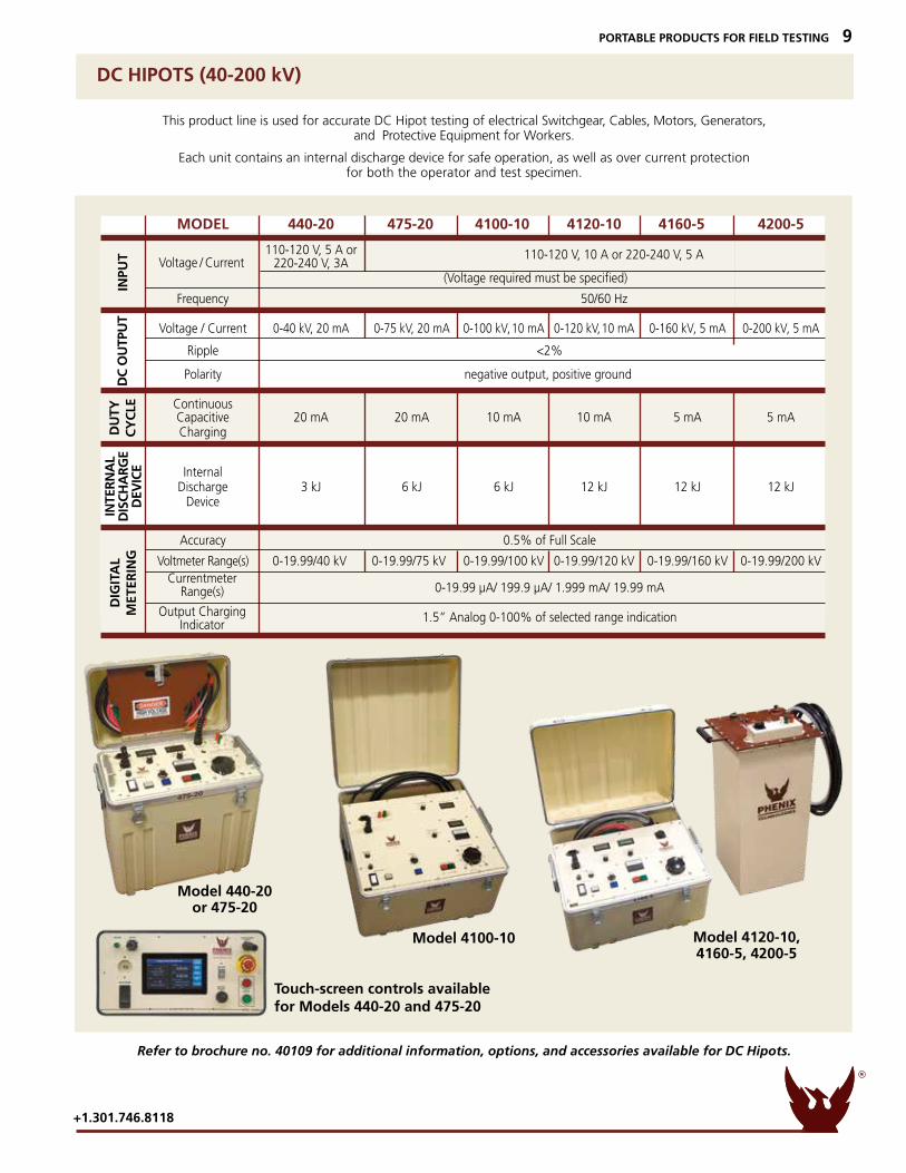
DC HIPOTS (40-200 kV)
This product line is used for accurate DC Hipot testing of electrical Switchgear, Cables, Motors, Generators, and Protective Equipment for Workers.
Each unit contains an internal discharge device for safe operation, as well as over current protection for both the operator and test specimen.
Refer to brochure no. 40109 for additional information, options, and accessories available for DC Hipots.
Model 4100-10 Model 4120-10,4160-5, 4200-5
Touch-screen controls available for Models 440-20 and 475-20
Model 440-20or 475-20
INPU
TD
C O
UTP
UT
DIG
ITA
LM
ETER
ING
DU
TY
CY
CLE
INTE
RN
AL
DIS
CH
AR
GE
DEV
ICE
Output Charging Indicator
CurrentmeterRange(s)
Voltage / Current
MODEL 440-20 475-20 4100-10 4120-10 4160-5 4200-5
110-120 V, 5 A or 220-240 V, 3A (Voltage required must be specified)
Frequency 50/60 Hz Voltage / Current 0-40 kV, 20 mA 0-75 kV, 20 mA 0-100 kV, 10 mA 0-120 kV, 10 mA 0-160 kV, 5 mA 0-200 kV, 5 mA Ripple <2% Polarity negative output, positive ground Continuous Capacitive 20 mA 20 mA 10 mA 10 mA 5 mA 5 mA Charging Internal Discharge 3 kJ 6 kJ 6 kJ 12 kJ 12 kJ 12 kJ Device
Accuracy 0.5% of Full Scale
Voltmeter Range(s) 0-19.99/40 kV 0-19.99/75 kV 0-19.99/100 kV 0-19.99/120 kV 0-19.99/160 kV 0-19.99/200 kV
0-19.99 µA/ 199.9 µA/ 1.999 mA/ 19.99 mA 1.5” Analog 0-100% of selected range indication
110-120 V, 10 A or 220-240 V, 5 A
TECHNOLOGIES
PHENIX
R
+1.301.746.8118
PORTABLE PRODUCTS FOR FIELD TESTING 9
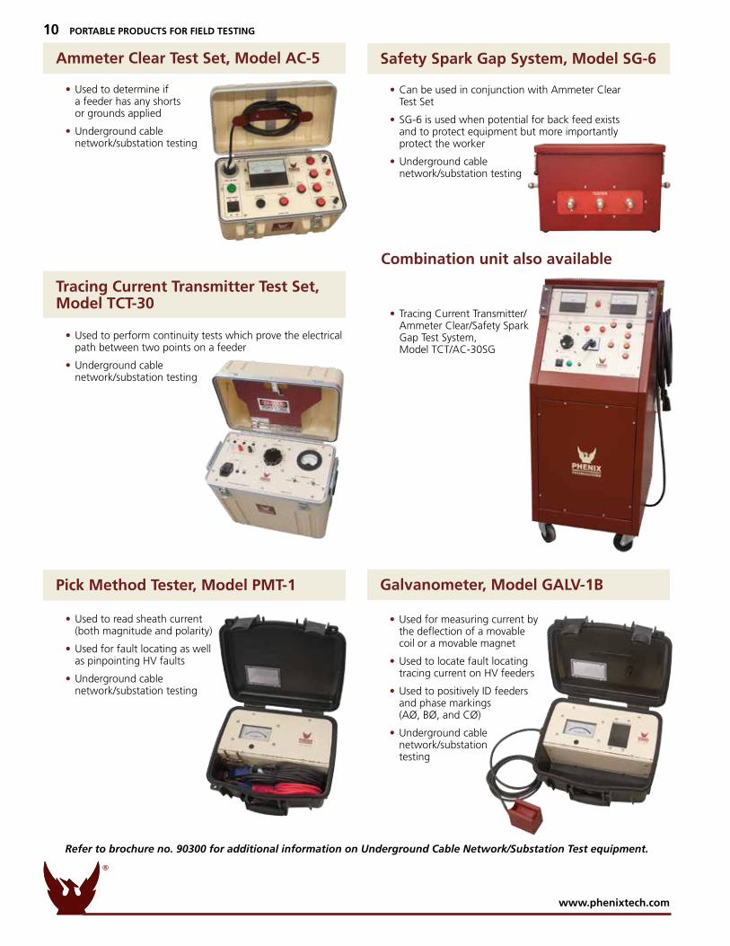
• Used to read sheath current (both magnitude and polarity)
• Used for fault locating as well as pinpointing HV faults
• Underground cable network/substation testing
• Used for measuring current by the deflection of a movable coil or a movable magnet
• Used to locate fault locating tracing current on HV feeders
• Used to positively ID feeders and phase markings (AØ, BØ, and CØ)
• Underground cable network/substation testing
• Used to perform continuity tests which prove the electrical path between two points on a feeder
• Underground cable network/substation testing
Pick Method Tester, Model PMT-1 Galvanometer, Model GALV-1B
Tracing Current Transmitter Test Set, Model TCT-30
Combination unit also available
• Used to determine if a feeder has any shorts or grounds applied
• Underground cable network/substation testing
• Can be used in conjunction with Ammeter Clear Test Set
• SG-6 is used when potential for back feed exists and to protect equipment but more importantly protect the worker
• Underground cable network/substation testing
• Tracing Current Transmitter/ Ammeter Clear/Safety Spark Gap Test System, Model TCT/AC-30SG
Ammeter Clear Test Set, Model AC-5 Safety Spark Gap System, Model SG-6
TECHNOLOGIES
PHENIX
R
www.phenixtech.com
10 PORTABLE PRODUCTS FOR FIELD TESTING
Refer to brochure no. 90300 for additional information on Underground Cable Network/Substation Test equipment.
TECHNOLOGIES
PHENIX
R
+1.301.746.8118
PORTABLE PRODUCTS FOR FIELD TESTING 11
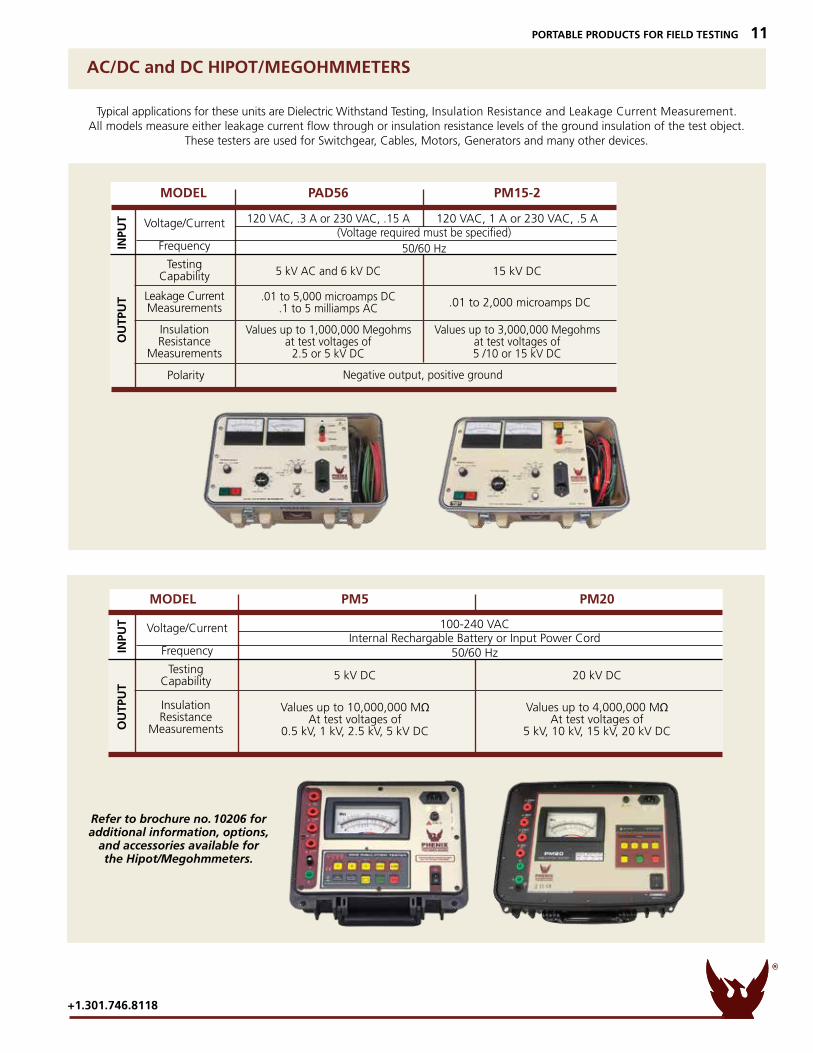
AC/DC and DC HIPOT/MEGOHMMETERS
Refer to brochure no. 10206 for additional information, options,
and accessories available for the Hipot/Megohmmeters.
Typical applications for these units are Dielectric Withstand Testing, Insulation Resistance and Leakage Current Measurement.All models measure either leakage current flow through or insulation resistance levels of the ground insulation of the test object.
These testers are used for Switchgear, Cables, Motors, Generators and many other devices.
INPU
TO
UTP
UT
TestingCapability
Voltage/Current
Frequency
InsulationResistance
Measurements
MODEL PM5 PM20
100-240 VAC Internal Rechargable Battery or Input Power Cord 50/60 Hz 5 kV DC 20 kV DC
Values up to 10,000,000 MΩ Values up to 4,000,000 MΩ At test voltages of At test voltages of 0.5 kV, 1 kV, 2.5 kV, 5 kV DC 5 kV, 10 kV, 15 kV, 20 kV DC
INPU
TO
UTP
UT
TestingCapability
Voltage/Current
Frequency
Polarity
Leakage CurrentMeasurements
InsulationResistance
Measurements
MODEL PAD56 PM15-2
120 VAC, .3 A or 230 VAC, .15 A 120 VAC, 1 A or 230 VAC, .5 A (Voltage required must be specified) 50/60 Hz 5 kV AC and 6 kV DC 15 kV DC
.01 to 5,000 microamps DC .1 to 5 milliamps AC
Values up to 1,000,000 Megohms Values up to 3,000,000 Megohms at test voltages of at test voltages of 2.5 or 5 kV DC 5 /10 or 15 kV DC
Negative output, positive ground
.01 to 2,000 microamps DC
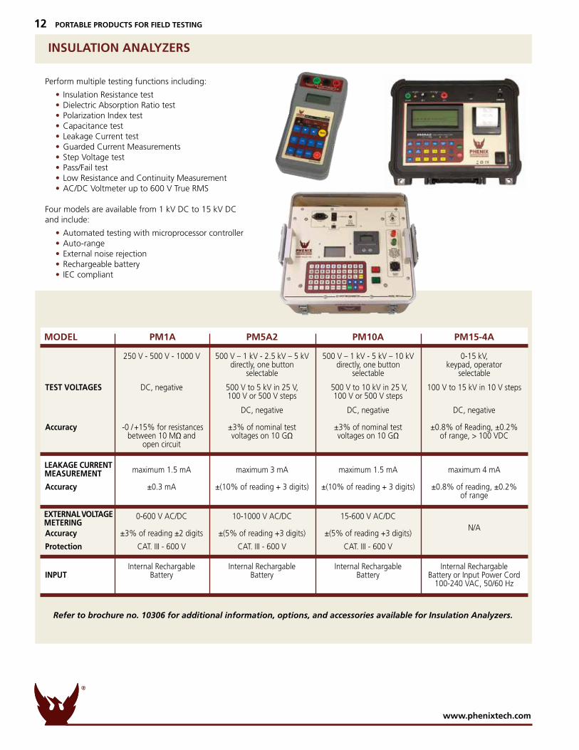
INSULATION ANALYZERS
Perform multiple testing functions including:
• Insulation Resistance test • Dielectric Absorption Ratio test • Polarization Index test • Capacitance test • Leakage Current test • Guarded Current Measurements • Step Voltage test • Pass/Fail test • Low Resistance and Continuity Measurement • AC/DC Voltmeter up to 600 V True RMS
Four models are available from 1 kV DC to 15 kV DC and include:
• Automated testing with microprocessor controller • Auto-range • External noise rejection • Rechargeable battery • IEC compliant
Refer to brochure no. 10306 for additional information, options, and accessories available for Insulation Analyzers.
250 V - 500 V - 1000 V 500 V – 1 kV - 2.5 kV – 5 kV 500 V – 1 kV - 5 kV – 10 kV 0-15 kV, directly, one button directly, one button keypad, operator selectable selectable selectable
TEST VOLTAGES DC, negative 500 V to 5 kV in 25 V, 500 V to 10 kV in 25 V, 100 V to 15 kV in 10 V steps 100 V or 500 V steps 100 V or 500 V steps
DC, negative DC, negative DC, negative
Accuracy -0 / +15% for resistances ±3% of nominal test ±3% of nominal test ±0.8% of Reading, ±0.2% between 10 MΩ and voltages on 10 GΩ voltages on 10 GΩ of range, > 100 VDC open circuit
maximum 1.5 mA maximum 3 mA maximum 1.5 mA maximum 4 mA
Accuracy ±0.3 mA ±(10% of reading + 3 digits) ±(10% of reading + 3 digits) ±0.8% of reading, ±0.2% of range
0-600 V AC/DC 10-1000 V AC/DC 15-600 V AC/DC
Accuracy ±3% of reading ±2 digits ±(5% of reading +3 digits) ±(5% of reading +3 digits)
Protection CAT. III - 600 V CAT. III - 600 V CAT. III - 600 V Internal Rechargable Internal Rechargable Internal Rechargable Internal Rechargable INPUT Battery Battery Battery Battery or Input Power Cord 100-240 VAC, 50/60 Hz
MODEL PM1A PM5A2 PM10A PM15-4A
LEAKAGE CURRENT MEASUREMENT
EXTERNAL VOLTAGE METERING
N/A
TECHNOLOGIES
PHENIX
R
www.phenixtech.com
12 PORTABLE PRODUCTS FOR FIELD TESTING
TECHNOLOGIES
PHENIX
R
+1.301.746.8118
PORTABLE PRODUCTS FOR FIELD TESTING 13
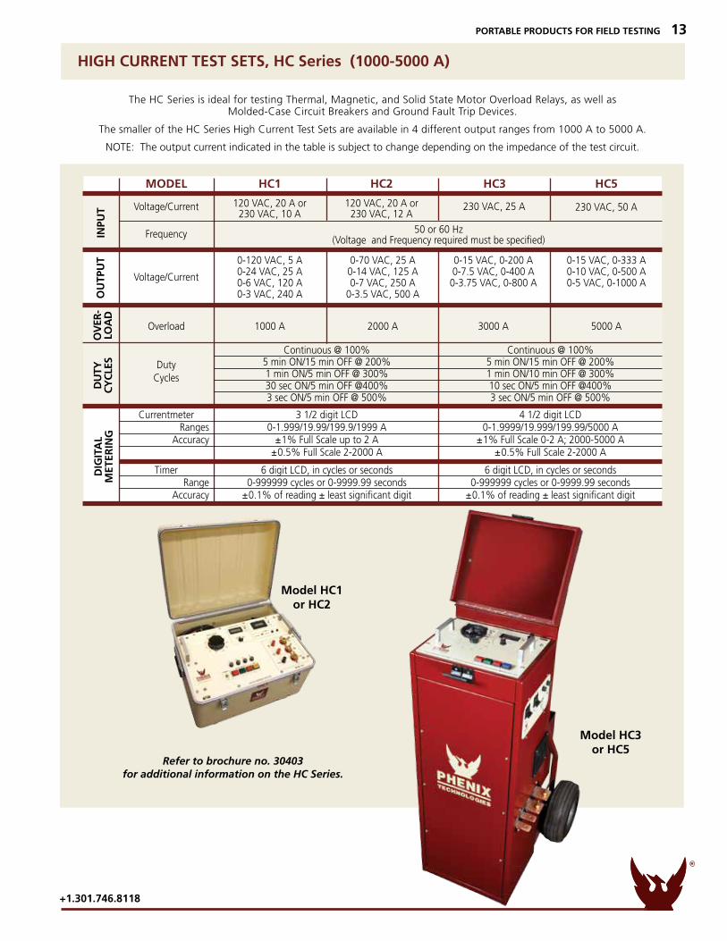
HIGH CURRENT TEST SETS, HC Series (1000-5000 A)
Refer to brochure no. 30403for additional information on the HC Series.
The HC Series is ideal for testing Thermal, Magnetic, and Solid State Motor Overload Relays, as well as Molded-Case Circuit Breakers and Ground Fault Trip Devices.
The smaller of the HC Series High Current Test Sets are available in 4 different output ranges from 1000 A to 5000 A.
NOTE: The output current indicated in the table is subject to change depending on the impedance of the test circuit.
Model HC3or HC5
Model HC1or HC2
INPU
TO
UTP
UT
DIG
ITA
LM
ETER
ING
DU
TY
CY
CLE
SO
VER
-LO
AD
Voltage/Current
DutyCycles
Voltage/Current
Frequency
230 VAC, 25 A 230 VAC, 50 A
MODEL HC1 HC2 HC3 HC5
120 VAC, 20 A or 120 VAC, 20 A or 230 VAC, 10 A 230 VAC, 12 A
50 or 60 Hz (Voltage and Frequency required must be specified) 0-120 VAC, 5 A 0-70 VAC, 25 A 0-15 VAC, 0-200 A 0-15 VAC, 0-333 A 0-24 VAC, 25 A 0-14 VAC, 125 A 0-7.5 VAC, 0-400 A 0-10 VAC, 0-500 A 0-6 VAC, 120 A 0-7 VAC, 250 A 0-3.75 VAC, 0-800 A 0-5 VAC, 0-1000 A 0-3 VAC, 240 A 0-3.5 VAC, 500 A
Overload 1000 A 2000 A 3000 A 5000 A Continuous @ 100% Continuous @ 100% 5 min ON/15 min OFF @ 200% 5 min ON/15 min OFF @ 200% 1 min ON/5 min OFF @ 300% 1 min ON/10 min OFF @ 300% 30 sec ON/5 min OFF @400% 10 sec ON/5 min OFF @400% 3 sec ON/5 min OFF @ 500% 3 sec ON/5 min OFF @ 500% Currentmeter 3 1/2 digit LCD 4 1/2 digit LCD Ranges 0-1.999/19.99/199.9/1999 A 0-1.9999/19.999/199.99/5000 A Accuracy ±1% Full Scale up to 2 A ±1% Full Scale 0-2 A; 2000-5000 A ±0.5% Full Scale 2-2000 A ±0.5% Full Scale 2-2000 A
Timer 6 digit LCD, in cycles or seconds 6 digit LCD, in cycles or seconds Range 0-999999 cycles or 0-9999.99 seconds 0-999999 cycles or 0-9999.99 seconds Accuracy ±0.1% of reading ± least significant digit ±0.1% of reading ± least significant digit
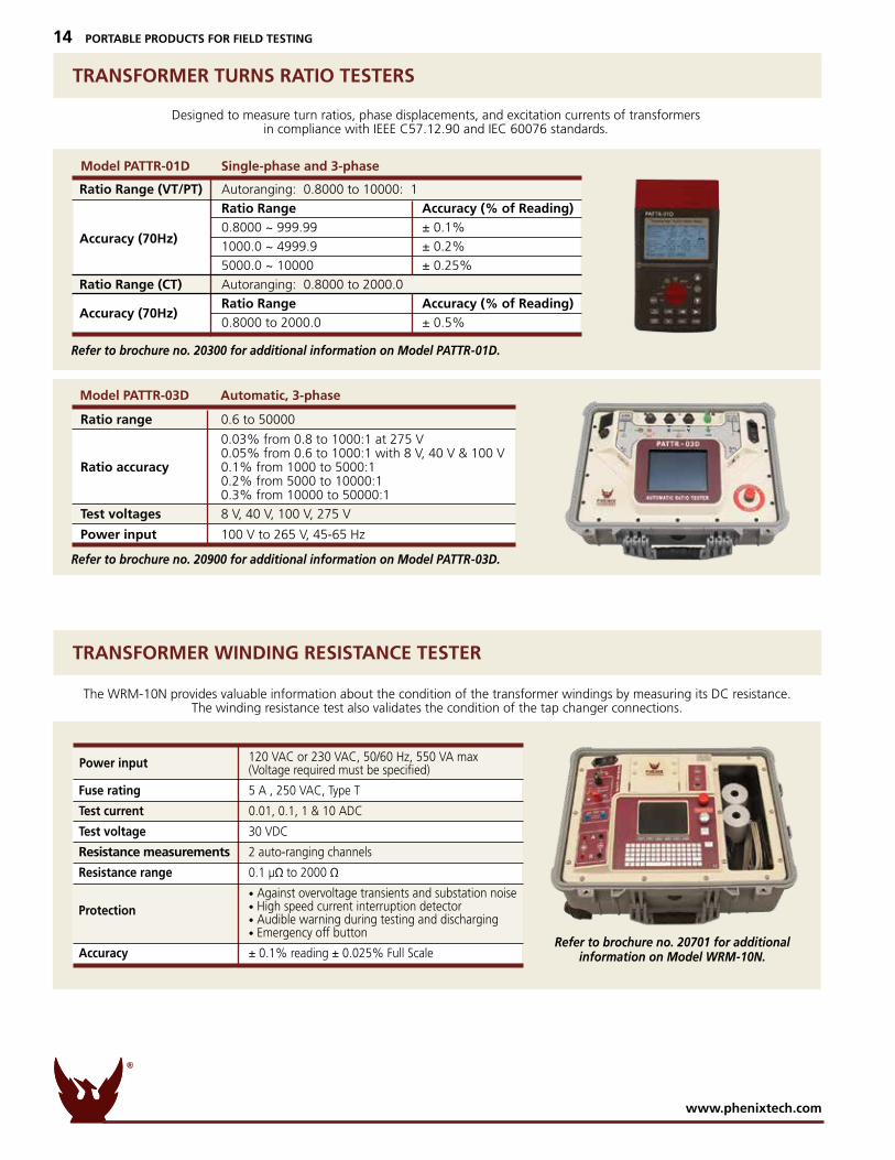
TRANSFORMER TURNS RATIO TESTERS
TRANSFORMER WINDING RESISTANCE TESTER
Designed to measure turn ratios, phase displacements, and excitation currents of transformersin compliance with IEEE C57.12.90 and IEC 60076 standards.
The WRM-10N provides valuable information about the condition of the transformer windings by measuring its DC resistance. The winding resistance test also validates the condition of the tap changer connections.
Refer to brochure no. 20900 for additional information on Model PATTR-03D.
Refer to brochure no. 20300 for additional information on Model PATTR-01D.
Refer to brochure no. 20701 for additionalinformation on Model WRM-10N.
120 VAC or 230 VAC, 50/60 Hz, 550 VA max (Voltage required must be specified)
Fuse rating 5 A , 250 VAC, Type T
Test current 0.01, 0.1, 1 & 10 ADC
Test voltage 30 VDC
Resistance measurements 2 auto-ranging channels
Resistance range 0.1 µΩ to 2000 Ω
• Against overvoltage transients and substation noise • High speed current interruption detector • Audible warning during testing and discharging • Emergency off button
Accuracy ± 0.1% reading ± 0.025% Full Scale
Protection
Power input
TECHNOLOGIES
PHENIX
R
www.phenixtech.com
14 PORTABLE PRODUCTS FOR FIELD TESTING
Ratio Range (VT/PT) Autoranging: 0.8000 to 10000: 1
Ratio Range Accuracy (% of Reading) 0.8000 ~ 999.99 ± 0.1%
1000.0 ~ 4999.9 ± 0.2%
5000.0 ~ 10000 ± 0.25%
Ratio Range (CT) Autoranging: 0.8000 to 2000.0
Ratio Range Accuracy (% of Reading) 0.8000 to 2000.0 ± 0.5%
Accuracy (70Hz)
Accuracy (70Hz)
Model PATTR-01D Single-phase and 3-phase
Ratio range 0.6 to 50000
0.03% from 0.8 to 1000:1 at 275 V 0.05% from 0.6 to 1000:1 with 8 V, 40 V & 100 V Ratio accuracy 0.1% from 1000 to 5000:1 0.2% from 5000 to 10000:1 0.3% from 10000 to 50000:1
Test voltages 8 V, 40 V, 100 V, 275 V
Power input 100 V to 265 V, 45-65 Hz
Model PATTR-03D Automatic, 3-phase
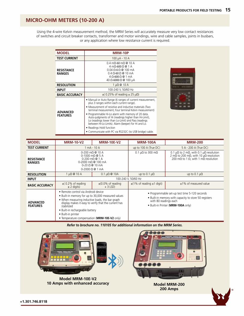
PORTABLE PRODUCTS FOR FIELD TESTING 15
Using the 4-wire Kelvin measurement method, the MRM Series will accurately measure very low contact resistances of switches and circuit breaker contacts, transformer and motor windings, wire and cable samples, joints in busbars,
or any application where low resistance current is required.
Refer to brochure no. 110105 for additional information on the MRM Series.
MICRO-OHM METERS (10-200 A)
Model MRM-200 200 Amps
Model MRM-10E-V2 10 Amps with enhanced accuracy
RESISTANCERANGES
BASIC ACCURACY
INPUTRESOLUTION
ADVANCEDFEATURES
• Remote control via Android device• Built-in memory for up to 30,000 measured values• When measuring inductive loads, the bar graph display makes it easy to verify that the current has stabilized• Built-in rechargeable battery• Built-in printer• Temperature compensation (MRM-10E-V2 only)
• Programmable set-up test time 5-120 seconds• Built-in memory with capacity to store 50 registers with 80 readings each• Built-in Printer (MRM-100A only)
MODEL MRM-10-V2 MRM-10E-V2 MRM-100A MRM-200TEST CURRENT 1 mA - 10 A up to 100 A (True DC) 5 A - 200 A (True DC)
0-200 mΩ @ 10 A 0.1 µΩ to 300 mΩ 0.1 µΩ to 2 mΩ, with 0.1 µΩ resolution 0-1000 mΩ @ 5 A 2 mΩ to 200 mΩ, with 10 µΩ resolution 0-200 mΩ @ 1 A 200 mΩ to 1 Ω, with 1 mΩ resolution 0-2000 mΩ @ 100 mA 0-20 Ω @ 10 mA 0-2000 Ω @ 1 mA 1 µΩ @ 10 A 0.1 µΩ @ 10A up to 0.1 µΩ up to 0.1 µΩ 100-240 V, 50/60 Hz ±( 0.2% of reading ±(0.0% of reading ±(1% of reading ±1 digit) ±1% of measured value ± 2 digits) + 3 LSD)
RESISTANCERANGES
BASIC ACCURACYINPUTRESOLUTION
ADVANCEDFEATURES
MODEL MRM-10P TEST CURRENT 100 µA - 10 A
0.4 mΩ-60 mΩ @ 10 A 4 mΩ-600 Ω @ 1 A 0.04 Ω-6 Ω @ 100 mA 0.4 Ω-60 Ω @ 10 mA 4 Ω-600 Ω @ 1 mA 40 Ω-6000 Ω @ 100 µA 1 µΩ @ 10 A 100-240 V, 50/60 Hz ±( 0.25% of reading ± 25 µΩ)
• Manual or Auto Range (6 ranges of current measurement, plus 3 ranges within each current range).• Measurement of resistive and inductive materials (Two terminal measurement; Four terminal Kelvin measurement)• Programmable Hi-Lo alarm with memory of 20 data. Auto-judgments of Hi (readings higher than Hi-Limit), Lo (readings lower than Lo-Limit) and Pass (readings between Hi-Lo Limits). Alarm (beeper) for Hi and Lo.• Readings Hold function• Communicate with PC via RS232C (to USB bridge) cable.
TECHNOLOGIES
PHENIX
R
+1.301.746.8118
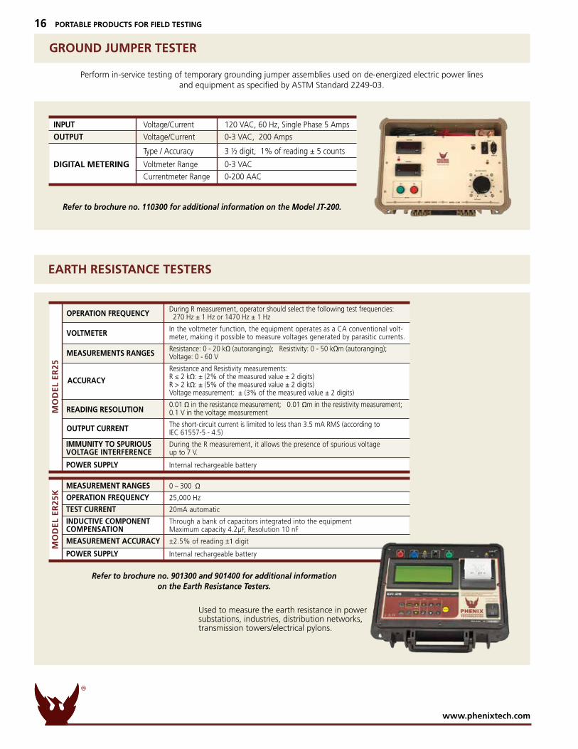
Perform in-service testing of temporary grounding jumper assemblies used on de-energized electric power lines and equipment as specified by ASTM Standard 2249-03.
Used to measure the earth resistance in power substations, industries, distribution networks, transmission towers/electrical pylons.
INPUT Voltage/Current 120 VAC, 60 Hz, Single Phase 5 Amps
OUTPUT Voltage/Current 0-3 VAC, 200 Amps
Type / Accuracy 3 ½ digit, 1% of reading ± 5 counts
Voltmeter Range 0-3 VAC
Currentmeter Range 0-200 AAC
DIGITAL METERING
Refer to brochure no. 110300 for additional information on the Model JT-200.
Refer to brochure no. 901300 and 901400 for additional informationon the Earth Resistance Testers.
GROUND JUMPER TESTER
EARTH RESISTANCE TESTERS
TECHNOLOGIES
PHENIX
R
www.phenixtech.com
16 PORTABLE PRODUCTS FOR FIELD TESTING
During R measurement, operator should select the following test frequencies: 270 Hz ± 1 Hz or 1470 Hz ± 1 Hz
In the voltmeter function, the equipment operates as a CA conventional volt- meter, making it possible to measure voltages generated by parasitic currents.
Resistance: 0 - 20 kΩ (autoranging); Resistivity: 0 - 50 kΩm (autoranging); Voltage: 0 - 60 V
Resistance and Resistivity measurements: R ≤ 2 kΩ: ± (2% of the measured value ± 2 digits) R > 2 kΩ: ± (5% of the measured value ± 2 digits) Voltage measurement: ± (3% of the measured value ± 2 digits)
0.01 Ω in the resistance measurement; 0.01 Ωm in the resistivity measurement; 0.1 V in the voltage measurement
The short-circuit current is limited to less than 3.5 mA RMS (according to IEC 61557-5 - 4.5)
IMMUNITY TO SPURIOUS During the R measurement, it allows the presence of spurious voltage VOLTAGE INTERFERENCE up to 7 V.
POWER SUPPLY Internal rechargeable battery
MEASUREMENT RANGES 0 – 300 Ω
OPERATION FREQUENCY 25,000 Hz
TEST CURRENT 20mA automatic
INDUCTIVE COMPONENT Through a bank of capacitors integrated into the equipment COMPENSATION Maximum capacity 4.2µF, Resolution 10 nF
MEASUREMENT ACCURACY ±2.5% of reading ±1 digit
POWER SUPPLY Internal rechargeable battery
ACCURACY
OPERATION FREQUENCY
VOLTMETER
MEASUREMENTS RANGES
OUTPUT CURRENT
READING RESOLUTIONMO
DE
L E
R2
5M
OD
EL
ER
25
K

TECHNOLOGIES
PHENIX
R
+1.301.746.8118
PORTABLE PRODUCTS FOR FIELD TESTING 17
Refer to brochure no. 90605 for additional information on the KVM Series.
AC/DC KILOVOLTMETERS, KVM Series (50-300 kV)
The KVM Series can be used for calibration and general high voltage measurements.Precise and accurate voltage measurement functions include AC AVERAGE, AC RMS,
AC PEAK, AC PEAK/√2, DC AVERAGE, DC PEAK, DC RIPPLE.
SPEC
IFIC
ATI
ON
S
MODEL KVM50A KVM100A KVM200A KVM300A
100-240 VAC, 0.4 A, 47-63 Hz, Single Phase
BATTERY POWER 9.6 V, Ni-MH, 3200 mA hr
INPUT CHARGING JACK +15 VDC, 1.5 A
RESOLUTION RANGE RANGE RANGE RANGE
1 VOLT 0-20 kV 0-20 kV 0-20 kV n/a
10 VOLT 0-50 kV 0-100 kV 0-200 kV 0-30 kV
100 VOLT n/a n/a n/a 0-300 kV
HIGH VOLTAGE INPUT
LOW RANGE 0-30 kV AC/DC 0-20 kV AC/DC 0-20 kV AC/DC 0-30 kV AC/DC
HIGH RANGE 0-50 kV AC/DC 0-100 kV AC/DC 0-200 kV AC/DC 0-300 kV AC/DC
PEAK AC 0-71 kV 0-141 kV 0-200 kV 0-424 kV
DIVIDER IMPEDANCE
RESISTANCE 300 M Ohms 380 M Ohms 760 M Ohms 1200 M Ohms
CAPACITANCE 15 pF 200 pF 100 pF 200 pF
RATIO 10,000:1 10,000:1 10,000:1 10,000:1
INPUT POWER
Model KVM200A
Model KVM300A
Refer to brochure no. 70303 for additional information on the Variable Voltage Power Supplies.
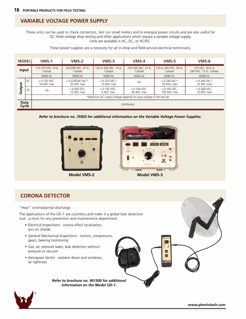
VARIABLE VOLTAGE POWER SUPPLY
CORONA DETECTOR
These units can be used to check contactors, test run small motors and to energize power circuits and are also useful for DC fields voltage drop testing and other applications which require a variable voltage supply.
Units are available in AC, DC, or AC/DC.
These power supplies are a necessity for all in-shop and field-service electrical technicians.
“Hear” corona/partial discharge.
The applications of the UD-1 are countless and make it a global leak detection tool: a must for any prevention and maintenance department.
• Electrical Inspections: corona effect localization, arcs on shields
• General Mechanical Inspections: motors, compressors, gears, bearing monitoring
• Gas, air, pressure leaks, leak detection without pressure or vacuum
• Aerospace Sector: airplane doors and windows, air tightness
Model VMS-2 Model VMS-3
Input
Ou
tpu
t AC
DC
n/a
DutyCycle
MODEL VMS-1 VMS-2 VMS-3 VMS-4 VMS-5 VMS-8 110-120 VAC, 10 A, 220-240 VAC, 25 A, 120 or 240 VAC, 10 A, 220-240 VAC, 25 A, 120 or 240 VAC, 50 A, 120 VAC, 30 A or 1-phase 1-phase 1-phase 1-phase 1-phase 240 VAC, 15 A, 1-phase 50/60 Hz 50/60 Hz 50/60 Hz 50/60 Hz 50/60 Hz 50/60 Hz
≈ 0-120 VAC, ≈ 0-220/240 VAC*, ≈ 0-120 VAC*, ≈ 0-240 VAC*, ≈ 0-240 VAC*, 10 AAC max 25 AAC max 10 AAC max 50 AAC max 10 AAC max
≈ 0-300 VDC, ≈ 0-150 VDC, ≈ 0-100 VDC, ≈ 0-100 VDC, ≈ 0-300 VDC, 10 ADC max 5 ADC max 40 ADC max 100 ADC max 10 ADC max
*Maximum AC output voltage depends on input voltage of the test set continuous
n/a
TECHNOLOGIES
PHENIX
R
www.phenixtech.com
18 PORTABLE PRODUCTS FOR FIELD TESTING
Refer to brochure no. 901500 for additional information on the Model UD-1.
TECHNOLOGIES
PHENIX
R
+1.301.746.8118
PORTABLE PRODUCTS FOR FIELD TESTING 19
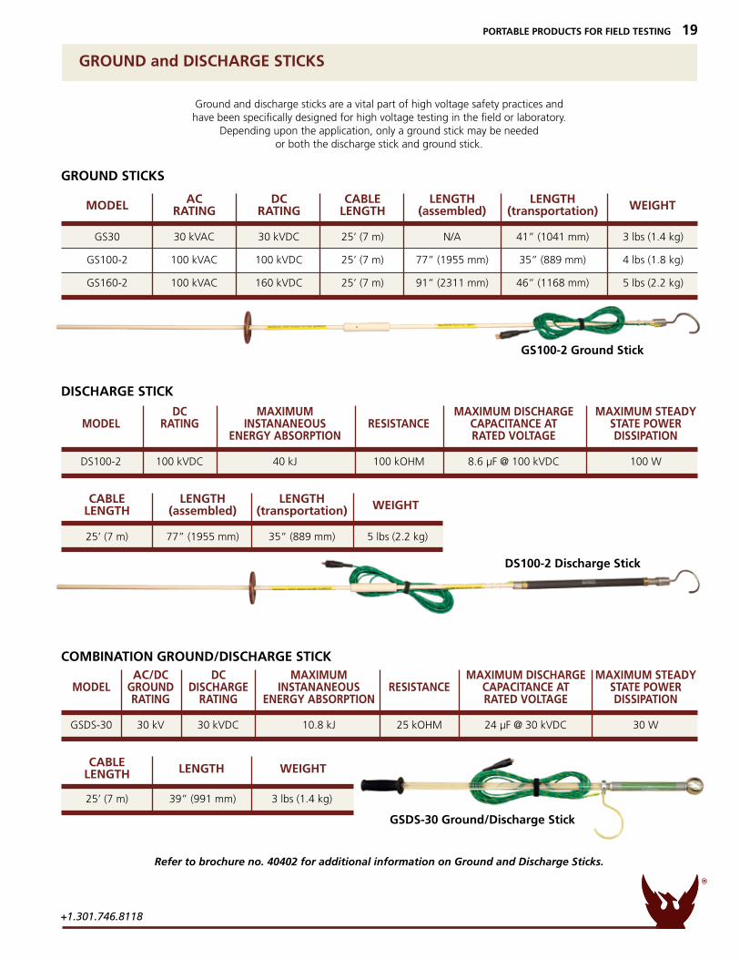
GROUND and DISCHARGE STICKS
Ground and discharge sticks are a vital part of high voltage safety practices andhave been specifically designed for high voltage testing in the field or laboratory.
Depending upon the application, only a ground stick may be neededor both the discharge stick and ground stick.
GS100-2 Ground Stick
DS100-2 Discharge Stick
GSDS-30 Ground/Discharge Stick
GROUND STICKS
DISCHARGE STICK
COMBINATION GROUND/DISCHARGE STICK
Refer to brochure no. 40402 for additional information on Ground and Discharge Sticks.
DC MAXIMUM MAXIMUM DISCHARGE MAXIMUM STEADY MODEL RATING INSTANANEOUS RESISTANCE CAPACITANCE AT STATE POWER ENERGY ABSORPTION RATED VOLTAGE DISSIPATION
DS100-2 100 kVDC 40 kJ 100 kOHM 8.6 µF @ 100 kVDC 100 W
AC/DC DC MAXIMUM MAXIMUM DISCHARGE MAXIMUM STEADY MODEL GROUND DISCHARGE INSTANANEOUS RESISTANCE CAPACITANCE AT STATE POWER RATING RATING ENERGY ABSORPTION RATED VOLTAGE DISSIPATION
GSDS-30 30 kV 30 kVDC 10.8 kJ 25 kOHM 24 µF @ 30 kVDC 30 W
AC DC CABLE LENGTH LENGTH RATING RATING LENGTH (assembled) (transportation)
GS30 30 kVAC 30 kVDC 25’ (7 m) N/A 41” (1041 mm) 3 lbs (1.4 kg)
GS100-2 100 kVAC 100 kVDC 25’ (7 m) 77” (1955 mm) 35” (889 mm) 4 lbs (1.8 kg)
GS160-2 100 kVAC 160 kVDC 25’ (7 m) 91” (2311 mm) 46” (1168 mm) 5 lbs (2.2 kg)
MODEL WEIGHT
CABLE LENGTH LENGTH LENGTH (assembled) (transportation)
25’ (7 m) 77” (1955 mm) 35” (889 mm) 5 lbs (2.2 kg)
WEIGHT
CABLE LENGTH
25’ (7 m) 39” (991 mm) 3 lbs (1.4 kg)
WEIGHTLENGTH
www.phenixtech.com © Copyright – Phenix Technologies, Inc. 10/2019
Branch OfficesPhenix Systems AGRiehenstrasse 62A, 4058 Basel, SwitzerlandPh: +41.61.383.2770 [email protected]
Phenix Asiazhong Cheng Rd, Sec 1, No 177, 2F, Taipei 11148 TaiwanPh: +886.2.2835.9738 • Fx: [email protected]
World Headquarters
Phenix Technologies, Inc.75 Speicher Drive
Accident, MD 21520 USAPh: +1.301.746.8118Fx: +1.301.895.5570
High Voltage • High Current • High Power Test Systems and Components
TECHNOLOGIES
PHENIX
R
20 PORTABLE PRODUCTS FOR FIELD TESTING
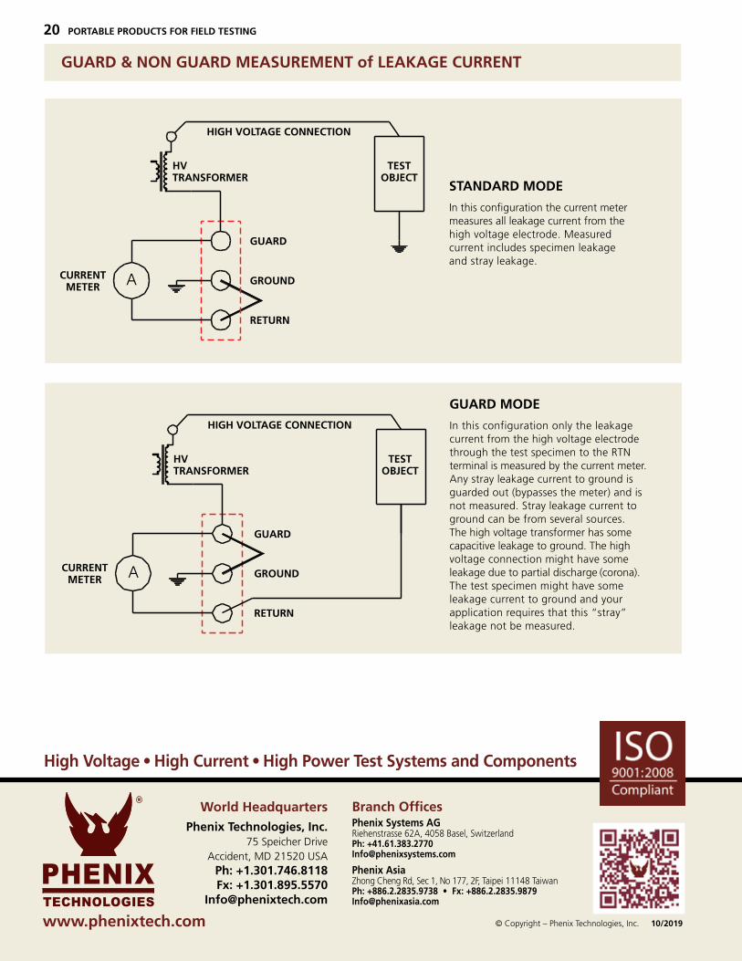
GUARD & NON GUARD MEASUREMENT of LEAKAGE CURRENT
GUARD MODE
In this configuration only the leakage current from the high voltage electrode through the test specimen to the RTN terminal is measured by the current meter. Any stray leakage current to ground is guarded out (bypasses the meter) and is not measured. Stray leakage current to ground can be from several sources. The high voltage transformer has some capacitive leakage to ground. The high voltage connection might have some leakage due to partial discharge (corona). The test specimen might have some leakage current to ground and your application requires that this “stray” leakage not be measured.
TESTOBJECT
CURRENTMETER A
CURRENTMETER A
STANDARD MODE
GUARD MODE
HVTRANSFORMER
GUARD
GROUND
RETURN
GUARD
GROUND
RETURN
HIGH VOLTAGE CONNECTION
TESTOBJECT
HVTRANSFORMER
HIGH VOLTAGE CONNECTION
STANDARD MODE
In this configuration the current meter measures all leakage current from the high voltage electrode. Measured current includes specimen leakage and stray leakage.
TESTOBJECT
CURRENTMETER A
CURRENTMETER A
STANDARD MODE
GUARD MODE
HVTRANSFORMER
GUARD
GROUND
RETURN
GUARD
GROUND
RETURN
HIGH VOLTAGE CONNECTION
TESTOBJECT
HVTRANSFORMER
HIGH VOLTAGE CONNECTION