Embed Size (px)
Citation preview
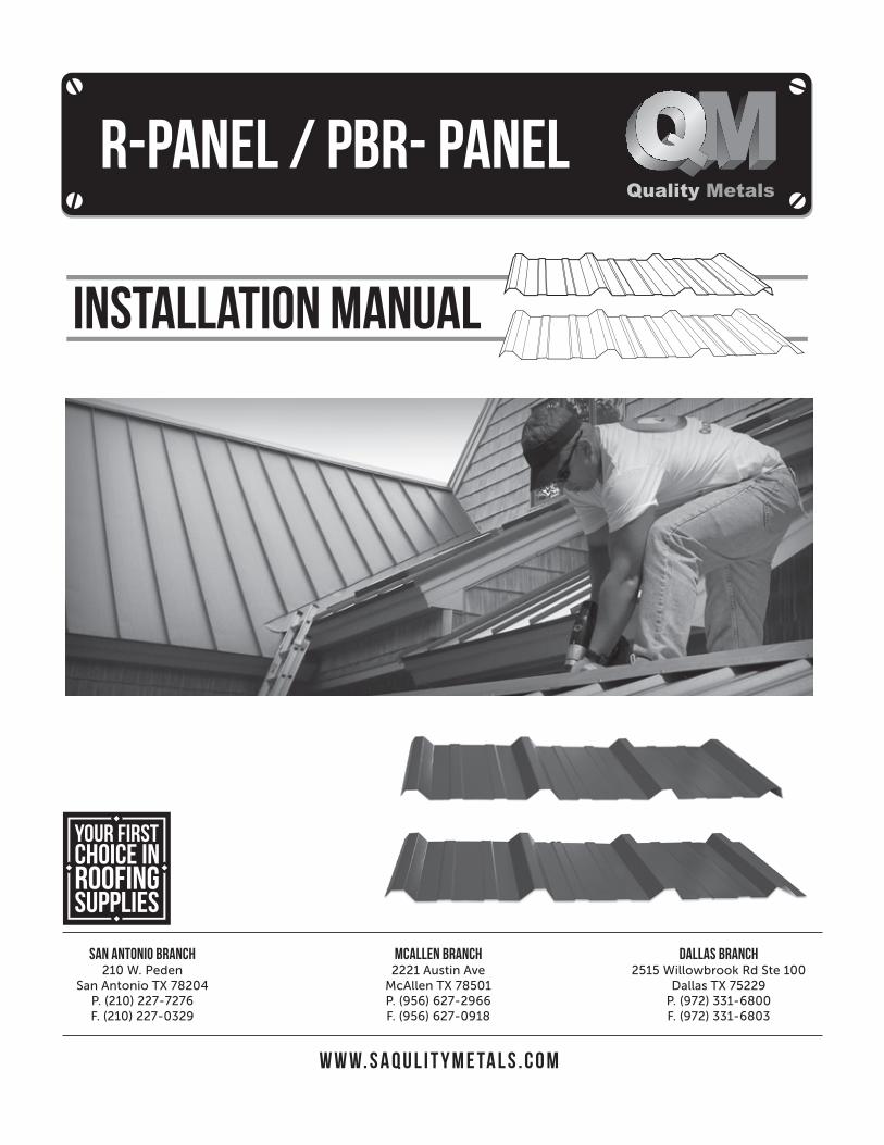
w w w. s a q u l i t y m e ta l s . c o m
san antonio branch210 W. Peden
San Antonio TX 78204P. (210) 227-7276F. (210) 227-0329
MCALLEN branch2221 Austin Ave
McAllen TX 78501P. (956) 627-2966F. (956) 627-0918
dallas branch2515 Willowbrook Rd Ste 100
Dallas TX 75229P. (972) 331-6800F. (972) 331-6803
R-PANEL / PBR- PANEL
- 1 -www.saqualitymetals.com
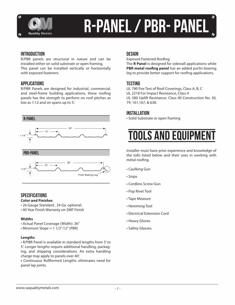
IntroductionR/PBR panels are structural in nature and can be installed either on solid substrate or open framing. This panel can be installed vertically or horizontally with exposed fasteners.
ApplicationsR/PBR Panels are designed for industrial, commercial,
panels has the strength to perform on roof pitches as low as 1:12 and on spans up to 5’.
SpecificationsColor and Finishes• 26 Gauge Standard , 24 Ga. optional.• 40 Year Finish Warranty on SMP Finish
Widths• Actual Panel Coverage (Width): 36”• Minimum Slope = 1 1/2":12" (PBR)
Lengths• R/PBR Panel is available in standard lengths from 3’ to 5’. Longer lengths require additional handling, packag-ing, and shipping considerations. An extra handling charge may apply to panels over 40’. • Continuous Rollformed Lengths: eliminates need for panel lap joints.
Design
The R Panel is designed for sidewall applications while has an added purlin bearing
TestingUL 790 Fire Test of Roof Coverings, Class A, B, CUL 2218 For Impact Resistance, Class 4UL 580 Uplift Resistance. Class 90 Construction No. 30, 79, 161,167, & 638.
INSTALLATION• Solid Substrate or open framing
Installer must have prior experience and knowledge of the tolls listed below and their uses in working with
• Caulking Gun
• Snips
• Cordless Screw Gun
• Pop Rivet Tool
• Tape Measure
• Hemming Tool
• Electrical Extension Cord
• Heavy Gloves
• Safety Glasses.
StorageBare Galvalume and painted panels can be expected to give many years of rust-free service when precautions are taken during storage.If metal is not to be used immediately, store inside in a well ventilated, dry location. Any outdoor storage is at the customer’s own risk! At time of delivery, inspect panels for moisture. If mois-ture has formed, the panels should be uncrated, wiped dry, and allowed to dry completely. Failure to remove the entrapped moisture between the sheets immedi-
Extended storage of panels in a bundle is not recom-mended. Storage on Roof, Crates need to be placed parallel to the framing members and the slope of the roof.
Strippable film Removal
applied to the topside of the panel to prevent possible damage to the painted surface. If panel has a protective
sunlight and high temperatures.
remain on the panels after installation.
Receiving MaterialsIt is the responsibility of the installer to unload material from the delivery truck. The installer shall be responsi-ble for providing suitable equipment for unloading of material from the delivery truck.After receiving material, check the condition of the material, and review the shipment against the shipping list to ensure all materials are accounted for. If damages or shortages are discovered, it should be noted on the shipping copy at time of delivery.If material is delivered by common carrier, a claim must be made with the carrier as soon as possible.
www.saqualitymetals.com
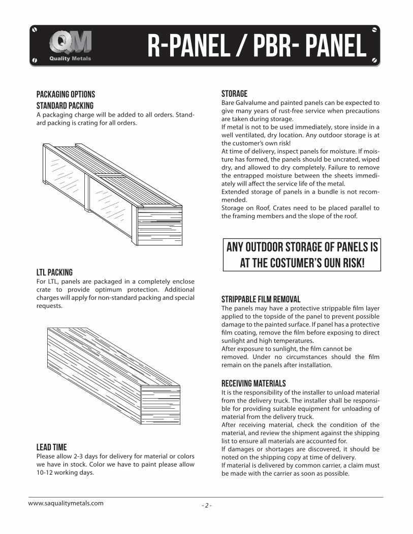
Packaging OptionsStandard packingA packaging charge will be added to all orders. Stand-ard packing is crating for all orders.
LTL packingFor LTL, panels are packaged in a completely enclose crate to provide optimum protection. Additional charges will apply for non-standard packing and special requests.
Lead TimePlease allow 2-3 days for delivery for material or colors we have in stock. Color we have to paint please allow 10-12 working days.
- 2 -
- 3 -www.saqualitymetals.com
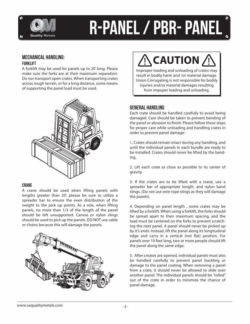
mechanical handling:ForkliftA forklift may be used for panels up to 20’ long. Please make sure the forks are at their maximum separation. Do nor transport open crates. When transporting crates across rough terrain, or for a long distance, some means of supporting the panel load must be used.
craneA crane should be used when lifting panels with lengths greater than 20’. please be sure to utilize a spreader bar to ensure the even distribution of the weight to the pick up points. As a rule, when lifting panels, no more than 1/3 of the length of the panel should be left unsupported. Canvas or nylon slings should be used to pick up the panels. DO NOT use cable or chains because this will damage the panels.
Improper loading and unloading of crates may result in bodily harm and /or material damage. Union Corrugating is not responsible for bodily
injuries and/or material damages resulting from impoper loading and unloading.
general handlingEach crate should be handled carefully to avoid being damaged. Care should be taken to prevent bending of
for proper care while unloading and handling crates in order to prevent panel damage:
1. Crates should remain intact during any handling, and until the individual panels in each bundle are ready to be installed. Crates should never be lifted by the band-ing.
2. Lift each crate as close as possible to its center of gravity.
3. If the crates are to be lifted with a crane, use a spreader bar of appropriate length, and nylon band slings. (Do not use wire rope slings as they will damage the panels).
4. Depending on panel length , some crates may be lifted by a forklift. When using a forklift, the forks should be spread apart to their maximum spacing, and the load must be centered on the forks to prevent scratch-ing the next panel. A panel should never be picked up by it’s ends. Instead, lift the panel along its longitudinal
panels over 10 feet long, two or more people should lift the panel along the same edge.
5. After creates are opened, individual panels must also be handled carefully to prevent panel buckling or damage to the panel coating. When removing a panel from a crate, it should never be allowed to slide over another panel. The individual panels should be “rolled” out of the crate in order to minimize the chance of panel damage.
- 4 -www.saqualitymetals.com
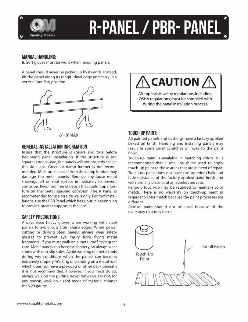
manual handling:6. Soft gloves must be worn when handling panels.
A panel should never be picked up by its ends. Instead, lift the panel along its longitudinal edge and carry in a
General Installation InformationInsure that the structure is square and true before beginning panel installation. If the structure is not square is not square, the panels will not properly seal at the side laps. Green or damp lumber is not recom-mended. Moisture released from the damp lumber may damage the metal panels. Remove any loose metal shavings left on roof surface immediately to prevent corrosion. Keep roof free of debris that could trap mois-ture on the metal, causing corrosion. The R Panel is recommended for use on side walls only. For roof instal-lations, use the PBR Panel which has a purlin bearing leg to provide greater support at the laps.
Safety Precautions Always wear heavy gloves when working with steel panels to avoid cuts from sharp edges. When power cutting or drilling steel panels, always wear safety
fragments. If you must walk on a metal roof, take great care. Metal panels can become slippery, so always wear shoes with non-slip soles. Avoid working on metal roofs during wet conditions when the panels can become extremely slippery. Walking or standing on a metal roof which does not have a plywood or other deck beneath it is not recommended. However, if you must do so, always walk on the purlins, never between. Do not, for any reason, walk on a roof made of material thinner than 29 gauge.
6’ - 8’ MAX
All applicable safety regulations, including OSHA regulations, must be complied with
during the panel installation process.
Touch Up Paint:
result in some small scratches or nicks to the paint
Touch-up paint is available in matching colors. It is recommended that a small brush be used to apply touch-up paint to those areas that are in need of repair. Touch-up paint does not have the superior chalk and
will normally discolor at an accelerated rate. Periodic touch-up may be required to maintain color match. There is no warranty on touch-up paint in regards to color match because the paint processes are
Aerosol paint should not be used because of the overspray that may occur.
Touch-UpPaint
Small Brush
- 5 -www.saqualitymetals.com
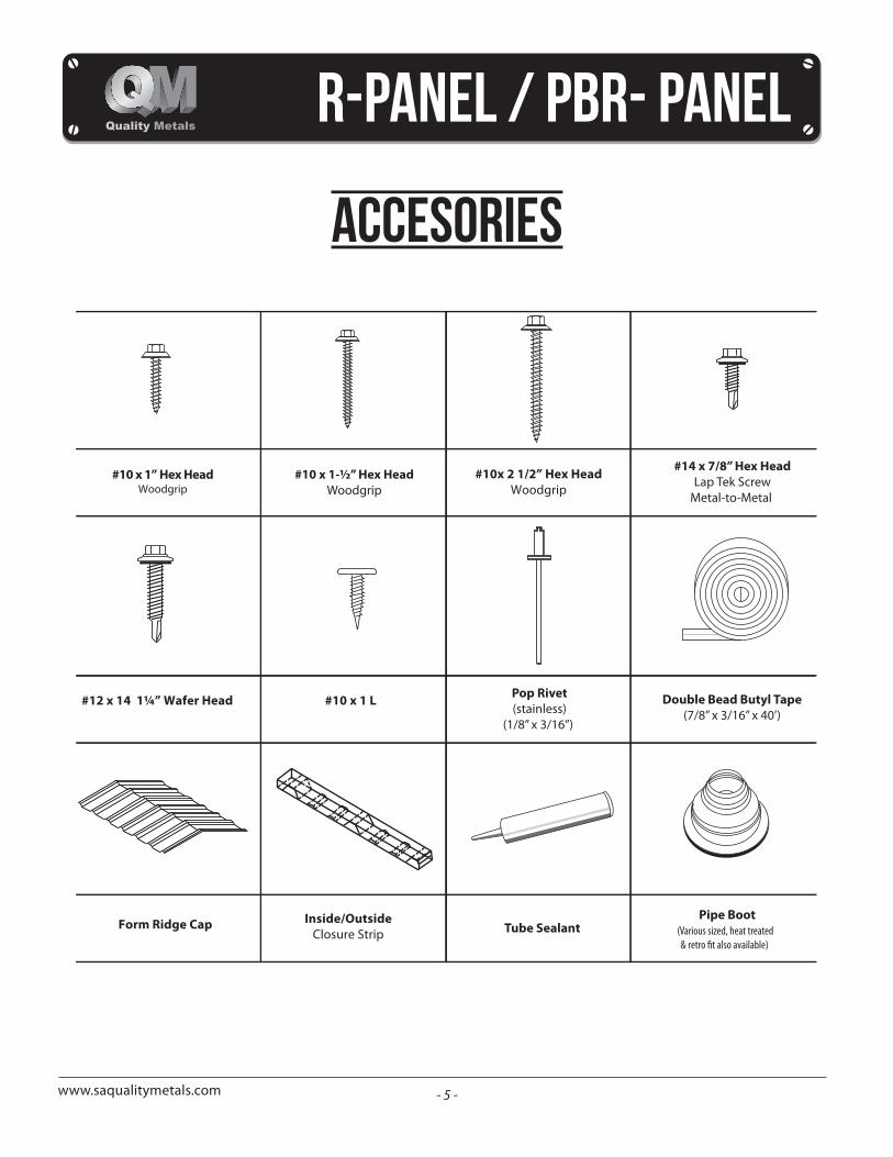
accesories
Double Bead Butyl Tape(7/8” x 3/16” x 40’)
#10 x 1-½” Hex HeadWoodgrip
#10x 2 1/2” Hex HeadWoodgrip
Tube Sealant
#10 x 1” Hex HeadWoodgrip
#14 x 7/8” Hex HeadLap Tek Screw
Metal-to-Metal
#12 x 14 1¼” Wafer Head
Inside/OutsideClosure Strip
Form Ridge Cap
#10 x 1 L Pop Rivet(stainless)
(1/8” x 3/16”)
Pipe Boot(Various sized, heat treated
- 6 -www.saqualitymetals.com
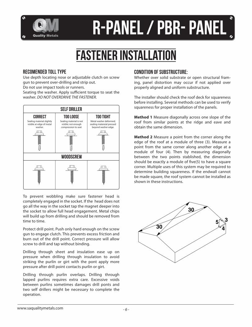
condition of substructure:Whether over solid substrate or open structural fram-ing, panel distortion may occur if not applied over properly aligned and uniform substructure.
The installer should check the roof deck for squareness before installing. Several methods can be used to verify squareness for proper installation of the panels.
Method 1 Measure diagonally across one slope of the roof from similar points at the ridge and eave and obtain the same dimension.
Method 2 Measure a point from the corner along the edge of the roof at a module of three (3). Measure a point from the same corner along another edge at a module of four (4). Then by measuring diagonally between the two points stablished, the dimension
corner. Multiple uses of this system may be required to determine building squareness. If the endwall cannot be made square, the roof system cannot be installed as shown in these instructions.
recomended toll typeUse depth locating nose or adjustable clutch on screw gun to prevent over-drilling and strip out.Do not use impact tools or runners.
washer. DO NOT OVERDRIVE THE FASTENER.
To prevent wobbling make sure fastener head is completely engaged in the socket. If the head does not go all the way in the socket tap the magnet deeper into the socket to allow full head engagement. Metal chips will build up from drilling and should be removed from time to time.
Protect drill point. Push only hard enough on the screw gun to engage clutch. This prevents excess friction and burn out of the drill point. Correct pressure will allow screw to drill and tap without binding.
Drilling through sheet and insulation ease up on pressure when drilling through insulation to avoid striking the purlin or girt with the pont apply more pressure after drill point contacts purlin or girt.
Drilling through purlin overlaps. Drilling through lapped purlins requires extra care. Excessive voids between purlins sometimes damages drill ponts and two self drillers might be necessary to complete the operation.
self driller
woodscrew
correct too loose too tightSealing material slightly visible at edge of metal
washer.
Sealing material is not visible; not enough
compression to seal.
Metal washer deformed; sealing matereial pressed
beyond washer edge.
fastener installation
- 7 -www.saqualitymetals.com
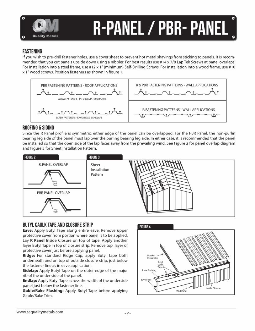
FasteningIf you wish to pre-drill fastener holes, use a cover sheet to prevent hot metal shavings from sticking to panels. It is recom-mended that you cut panels upside down using a nibbler. For best results use #14 x 7/8 Lap Tek Screws at panel overlaps. For installation into a steel frame, use #12 x 1" (minimum) Self-Drilling Screws. For installation into a wood frame, use #10
Roofing & Siding
bearing leg side of the panel must lap over the purling bearing leg side. In either case, it is recommended that the panel be installed so that the open side of the lap faces away from the prevailing wind. See Figure 2 for panel overlap diagram and Figure 3 for Sheet Installation Pattern.
Figure 2 Figure 3
Figure 4Butyl Caulk Tape and Closure StripEave: Apply Butyl Tape along entire eave. Remove upper protective cover from portion where panel is to be applied. Lay R Panel Inside Closure on top of tape. Apply another layer Butyl Tape in top of closure strip. Remove top layer of protective cover just before applying panel.Ridge: For standard Ridge Cap, apply Butyl Tape both underneath and on top of outside closure strip, just below the fastener line as in eave application.Sidelap: Apply Butyl Tape on the outer edge of the major rib of the under side of the panel.Endlap: Apply Butyl Tape across the width of the underside panel just below the fastener line.Gable/Rake Flashing: Apply Butyl Tape before applying Gable/Rake Trim.
- 8 -www.saqualitymetals.com
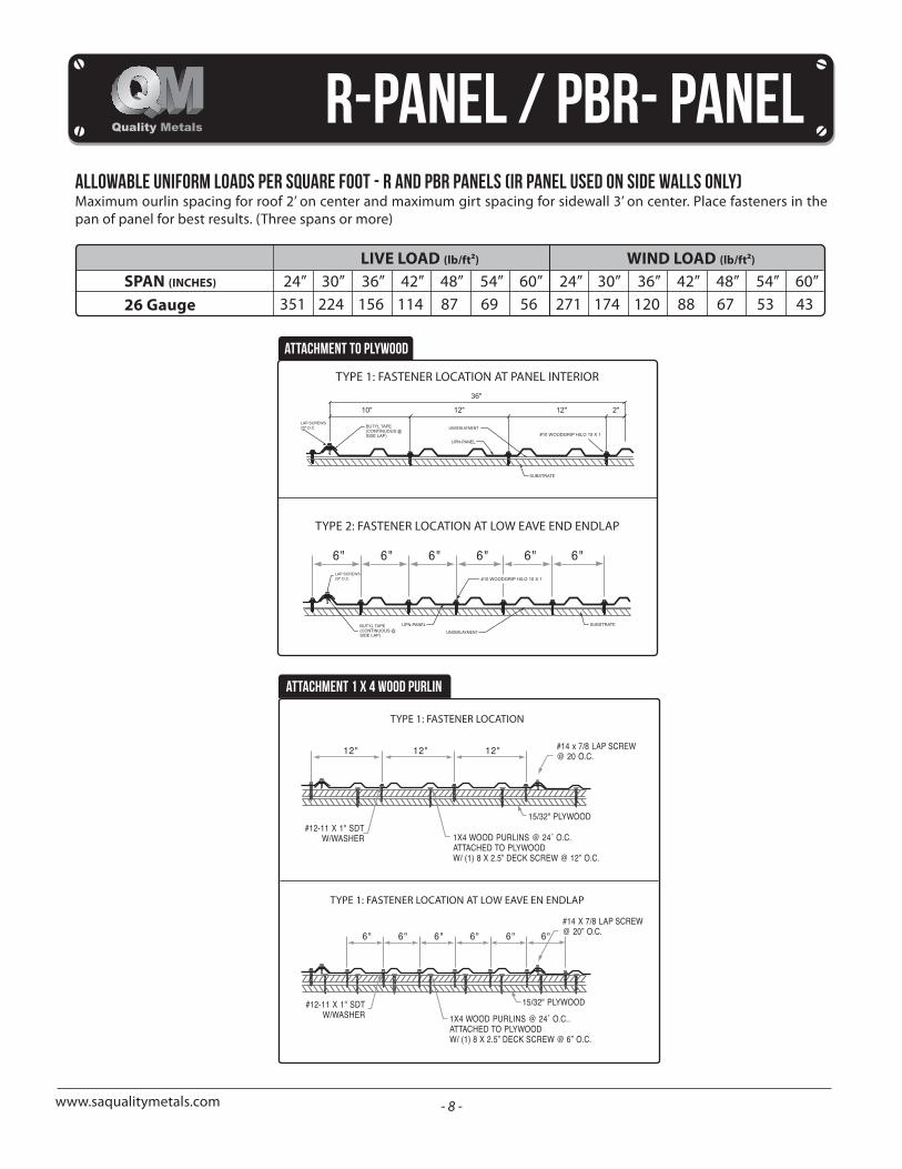
allowable uniform loads per square foot - r aND PBR PANELS (IR PANEL USED ON SIDE WALLS ONLY)Maximum ourlin spacing for roof 2’ on center and maximum girt spacing for sidewall 3’ on center. Place fasteners in the pan of panel for best results. (Three spans or more)
SPAN (INCHES)
LIVE LOAD (lb/ft²)
24”351
30”224
36”156
42”114
48”87
54”69
60”56
24”271
30”174
36”120
42”88
48”67
54”53
60”43
WIND LOAD (lb/ft²)
26 Gauge
TYPE 2: FASTENER LOCATION AT LOW EAVE END ENDLAP
#10 WOODGRIP HILO 10 X 1
TYPE 1: FASTENER LOCATION AT PANEL INTERIOR
#10 WOODGRIP HILO 10 X 1
ATTACHMENT TO PLYWOOD
ATTACHMENT 1 X 4 WOOD PURLIN
TYPE 1: FASTENER LOCATION
TYPE 1: FASTENER LOCATION AT LOW EAVE EN ENDLAP
- 9 -
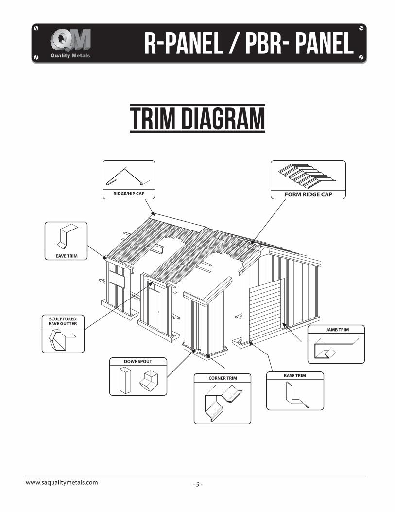
FORM RIDGE CAP
SCULPTUREDEAVE GUTTER
EAVE TRIM
RIDGE/HIP CAP
DOWNSPOUT
BASE TRIMCORNER TRIM
JAMB TRIM
www.saqualitymetals.com
trim diagram
- 10 -www.saqualitymetals.com
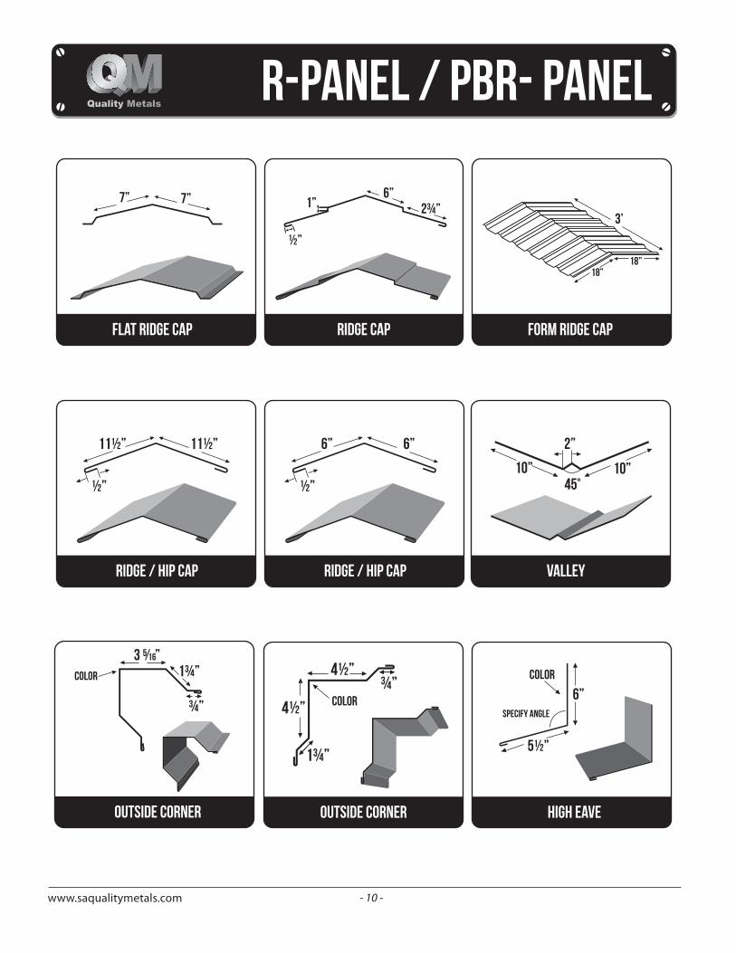
FLAT RIDGE CAP
7” 7”
RIDGE CAP
6”
3’
18”18”
1”
½”
2¾”
form RIDGE CAP
RIDGE / hip CAP
10”10”
2”
45°
11½” 11½”
½”
valleyRIDGE / hip CAP
6” 6”
½”
1¾”color
¾”
outside corner outside corner
4½”
color
color
4½”
1¾”
¾”
high eave
6”
5½”
specify angle
- 11 -www.saqualitymetals.com
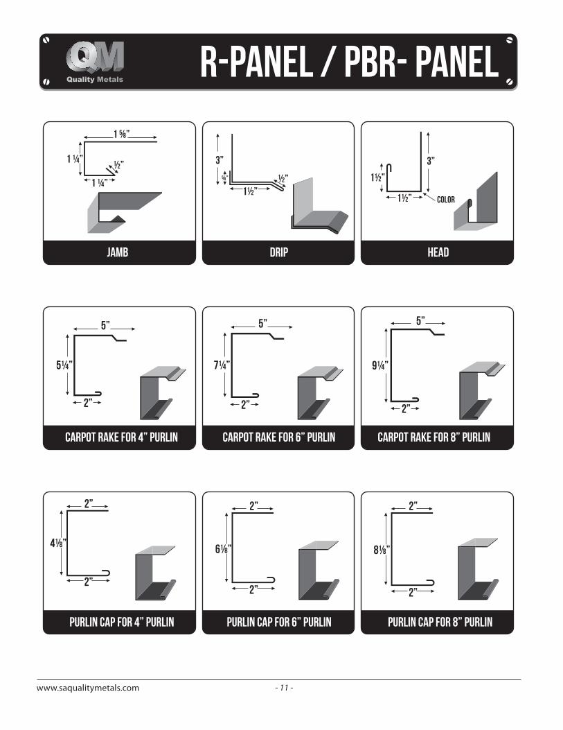
JAMB drip
1 ⅝”
1 ¼”
1 ¼”
½”
head
color
3” 3”
1½”
1½”1½”
½”⅝”
5”
2”
9¼”
CARPOT RAKE FOR 8” PURLIN
2”
6⅛”
2”
2”
8⅛”
2”
PURLIN CAP FOR 6” PURLIN PURLIN CAP FOR 8” PURLINPURLIN CAP FOR 4” PURLIN
2”
4⅛”
2”
CARPOT RAKE FOR 6” PURLIN
5”
2”
7¼”
CARPOT RAKE FOR 4” PURLIN
5”
2”
5¼”
- 12 -www.saqualitymetals.com
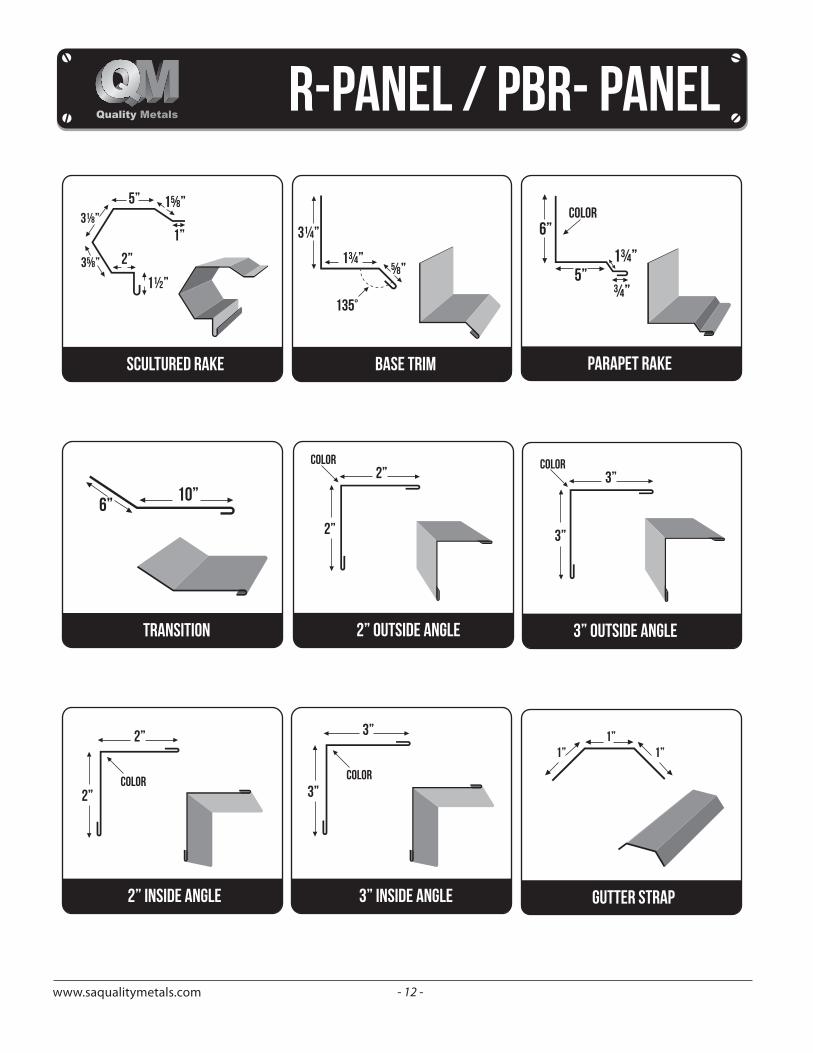
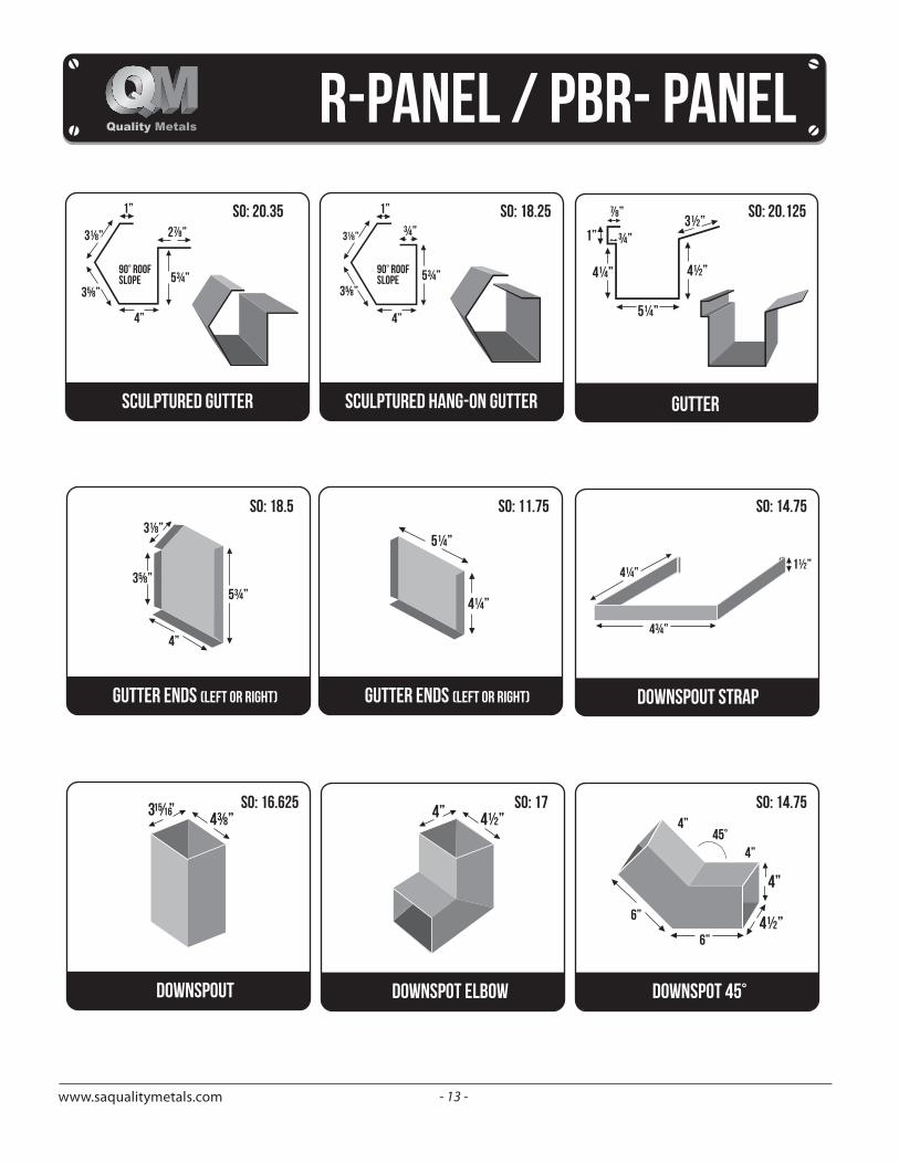
scultured rake base trim
5” 1⅝”
1”
1½”
2”3⅝”
3⅛”3¼”
1¾”
135°
⅝”
1”1” 1”
gutter strap
2” outside angle
2”
2”color
3” outside angle
3”
3”color
2”
2”color
2” inside angle 3” inside angle
3”
3”color
color
PARAPET RAKE
6”
5”1¾”
¾”
transition
10”6”
- 13 -www.saqualitymetals.com
gutter ends (left or right)
3⅛”
3⅝”
4”
5¾”
downspout
4⅜”
downspot elbow
4” 4½”
1½”4¼”
4¾”
downspout strap
downspot 45°
4”
4½”6”
6”
4”
4”45°
gutter
5¼”
4½”
3½”
4¼”
1”
⅞”
¾”
gutter ends (left or right)
4¼”
5¼”
3⅛” 2⅞” ¾”
1” 1”
5¾” 5¾”90° roofslope
90° roofslope
4” 4”
3⅝”
3⅛”
3⅝”
sculptured hang-on guttersculptured gutter
SO: 20.35 SO: 18.25 SO: 20.125
SO: 18.5 SO: 11.75 SO: 14.75
SO: 16.625 SO: 17 SO: 14.75
- 14 -www.saqualitymetals.com
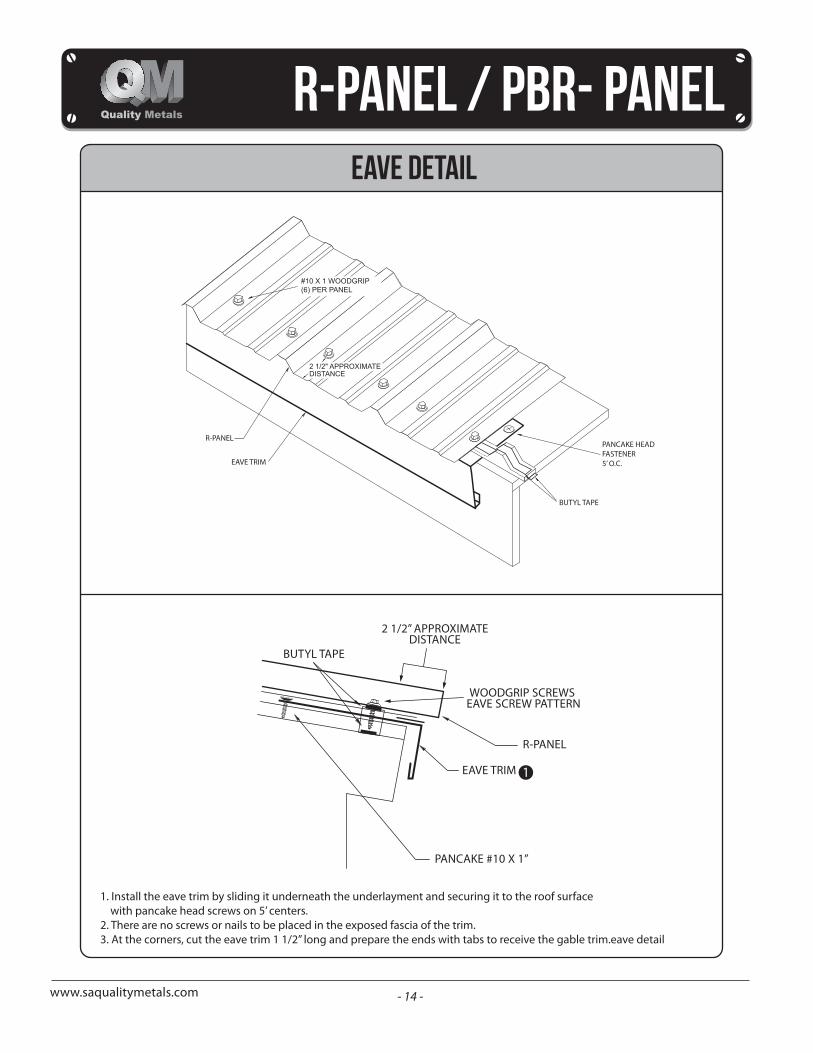
eave detail
BUTYL TAPE
2 1/2” APPROXIMATEDISTANCE
WOODGRIP SCREWS EAVE SCREW PATTERN
R-PANEL
EAVE TRIM
PANCAKE #10 X 1”
2 1/2" APPROXIMATEDISTANCE
#10 X 1 WOODGRIP(6) PER PANEL
1. Install the eave trim by sliding it underneath the underlayment and securing it to the roof surface with pancake head screws on 5’ centers.
2. There are no screws or nails to be placed in the exposed fascia of the trim.3. At the corners, cut the eave trim 1 1/2” long and prepare the ends with tabs to receive the gable trim.eave detail
R-PANEL
EAVE TRIM
BUTYL TAPE
PANCAKE HEAD FASTENER5’ O.C.
1
- 15 -www.saqualitymetals.com
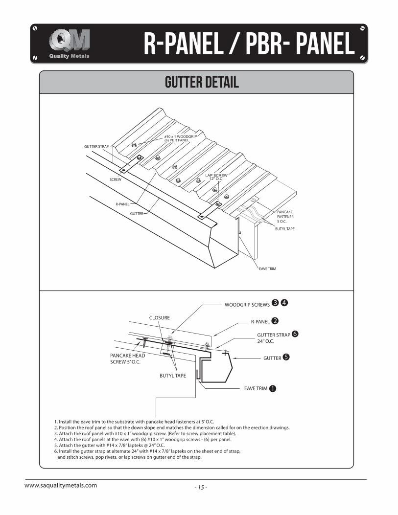
#10 x 1 WOODGRIP(6) PER PANEL
GUTTER detail
1. Install the eave trim to the substrate with pancake head fasteners at 5’ O.C.2. Position the roof panel so that the down slope end matches the dimension called for on the erection drawings.3. Attach the roof panel with #10 x 1” woodgrip screw. (Refer to screw placement table).4. Attach the roof panels at the eave with (6) #10 x 1” woodgrip screws - (6) per panel.5. Attach the gutter with #14 x 7/8” lapteks @ 24” O.C.6. Install the gutter strap at alternate 24” with #14 x 7/8” lapteks on the sheet end of strap,
and stitch screws, pop rivets, or lap screws on gutter end of the strap.
PANCAKE HEADSCREW 5’ O.C.
WOODGRIP SCREWS
CLOSURER-PANEL
GUTTER STRAP24” O.C.
GUTTER
EAVE TRIM
BUTYL TAPE
GUTTER STRAP
SCREW
R-PANEL
GUTTER
EAVE TRIM
PANCAKEFASTENER5 O.C.
BUTYL TAPE
3 4
2
6
5
1
- 16 -www.saqualitymetals.com
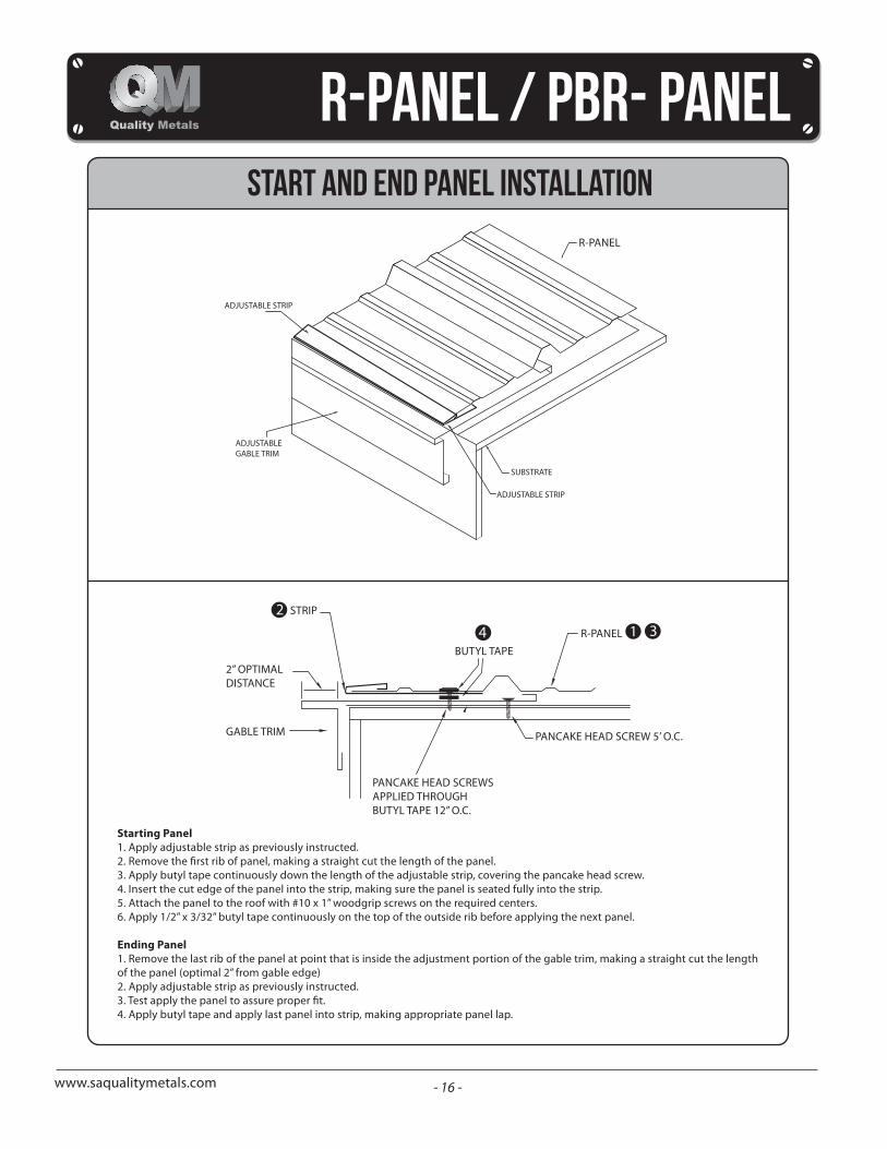
START AND END PANEL INSTALLATION
Starting Panel1. Apply adjustable strip as previously instructed.
3. Apply butyl tape continuously down the length of the adjustable strip, covering the pancake head screw.4. Insert the cut edge of the panel into the strip, making sure the panel is seated fully into the strip.5. Attach the panel to the roof with #10 x 1” woodgrip screws on the required centers.6. Apply 1/2” x 3/32” butyl tape continuously on the top of the outside rib before applying the next panel.
Ending Panel1. Remove the last rib of the panel at point that is inside the adjustment portion of the gable trim, making a straight cut the lengthof the panel (optimal 2” from gable edge)2. Apply adjustable strip as previously instructed.
4. Apply butyl tape and apply last panel into strip, making appropriate panel lap.
BUTYL TAPE
R-PANEL
PANCAKE HEAD SCREW 5’ O.C.
PANCAKE HEAD SCREWSAPPLIED THROUGH BUTYL TAPE 12” O.C.
GABLE TRIM
2” OPTIMALDISTANCE
STRIP
R-PANEL
ADJUSTABLE STRIP
ADJUSTABLEGABLE TRIM
SUBSTRATE
ADJUSTABLE STRIP
24 1 3
- 17 -www.saqualitymetals.com
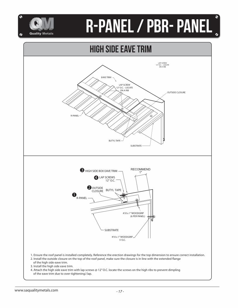
high side eave trim
1. Ensure the roof panel is installed completely. Reference the erection drawings for the top dimension to ensure correct installation.
of the high side eave trim.3. Install the high side eave trim.4. Attach the high side eave trim with lap screws @ 12” O.C. locate the screws on the high ribs to prevent dimpling
of the eave trim due to over-tightening.l lap.
EAVE TRIM
LAP SCREW12” O.C. - LOCATE
ON A RIBOUTSIDE CLOSURE
R-PANEL
BUTYL TAPE
SUBSTRATE
3
4
2
1
- 18 -www.saqualitymetals.com
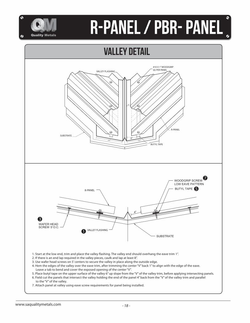
valley detail
2. If there is an end lap required in the valley pieces, caulk and lap at least 8”.3. Use wafer head screws on 5’ centers to secure the valley in place along the outside edge.4. Hem the edges of the valley over the eave trim, after trimming the center “V” back 1” to align with the edge of the eave.
Leave a tab to bend and cover the exposed opening of the center “V”.5. Place butyl tape on the upper surface of the valley 6” up slope from the “V” of the valley trim, before applying intersecting panels.6. Field cut the panels that intersect the valley holding the end of the panel 4” back from the “V” of the valley trim and parallel
to the “V” of the valley.7. Attach panel at valley using eave screw requirements for panel being installed.
VALLEY FLASHING
#10 X 1” WOODGRIP(6) PER PANEL
R-PANEL
BUTYL TAPE
SUBSTRATE
7
3
1
5
- 19 -www.saqualitymetals.com
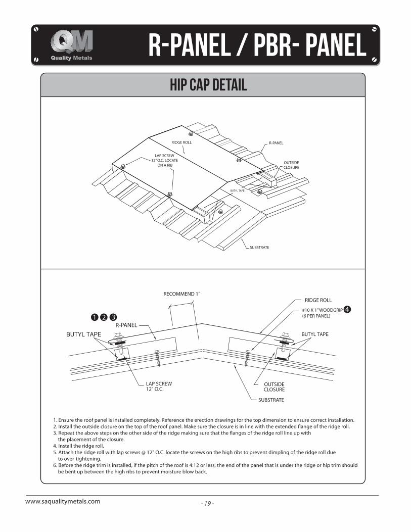
hip cap detail
1. Ensure the roof panel is installed completely. Reference the erection drawings for the top dimension to ensure correct installation.
the placement of the closure.4. Install the ridge roll.5. Attach the ridge roll with lap screws @ 12" O.C. locate the screws on the high ribs to prevent dimpling of the ridge roll due
to over-tightening.6. Before the ridge trim is installed, if the pitch of the roof is 4:12 or less, the end of the panel that is under the ridge or hip trim should
be bent up between the high ribs to prevent moisture blow back.
RIDGE ROLL
LAP SCREW 12” O.C. LOCATE
ON A RIB
R-PANEL
OUTSIDECLOSURE
SUBSTRATE
1 2 34#10 X 1” WOODGRIP
(6 PER PANEL)
- 20 -www.saqualitymetals.com
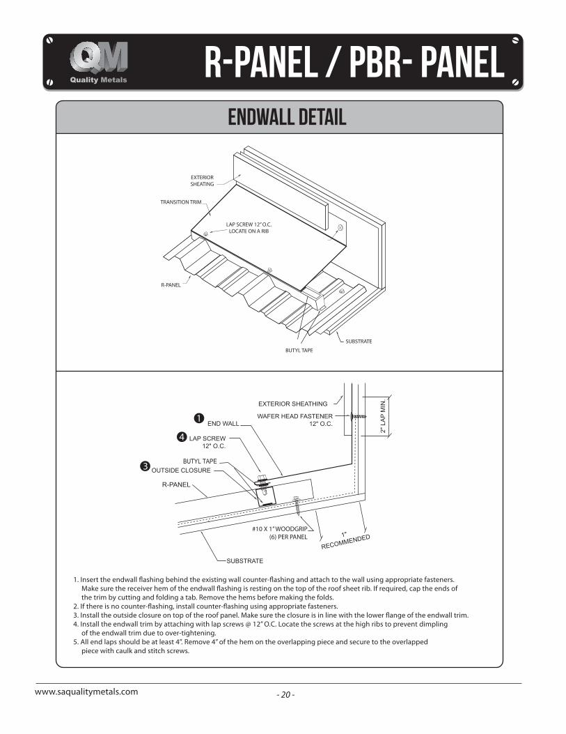
endwall detail
the trim by cutting and folding a tab. Remove the hems before making the folds.
4. Install the endwall trim by attaching with lap screws @ 12” O.C. Locate the screws at the high ribs to prevent dimplingof the endwall trim due to over-tightening.
5. All end laps should be at least 4”. Remove 4” of the hem on the overlapping piece and secure to the overlappedpiece with caulk and stitch screws.
EXTERIORSHEATING
TRANSITION TRIM
LAP SCREW 12” O.C.LOCATE ON A RIB
R-PANEL
BUTYL TAPE
SUBSTRATE
1
4
3
#10 X 1” WOODGRIP(6) PER PANEL
- 21 -www.saqualitymetals.com
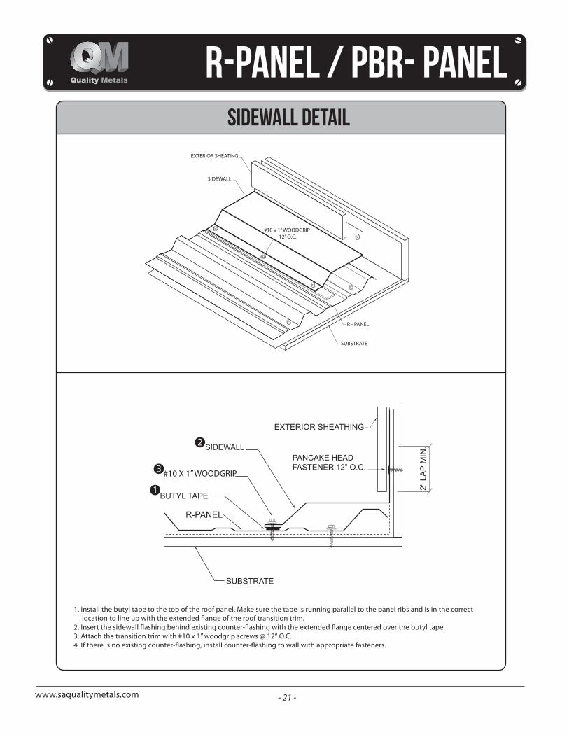
sidewall detail
1. Install the butyl tape to the top of the roof panel. Make sure the tape is running parallel to the panel ribs and is in the correct
3. Attach the transition trim with #10 x 1” woodgrip screws @ 12“ O.C.
EXTERIOR SHEATING
SIDEWALL
#10 x 1” WOODGRIP 12” O.C.
R - PANEL
SUBSTRATE
2
3
1
#10 X 1” WOODGRIP
- 22 -www.saqualitymetals.com
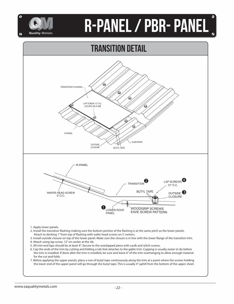
transition detail
1. Apply lower panels.
4. Attach using lap screw, 12” on center at the rib.5. All trim end laps should be at least 4”. Secure to the overlapped piece with caulk and stitch screws.6. Cap the ends of the trim by cutting and folding a tab that attaches to the gable trim. Capping is usually easier to do before
the trim is installed. If done after the trim is installed, be sure and leave 6” of the trim overhanging to allow enough materialfor the cut and folds.
7. Before applying the upper panels, place a row of butyl tape continuously along the trim at a point where the screws holdingthe lower end of the upper panel will go through the butyl tape. This is usually 4” uphill from the bottom of the upper sheet.
TRANSITION FLASHING
OUTSIDECLOSURE
SUBSTRATE
BUTYL TAPE
R-PANEL
LAP SCREW 12” O.C.LOCATE ON A RIB
1
2 4
3
- 23 -www.saqualitymetals.com
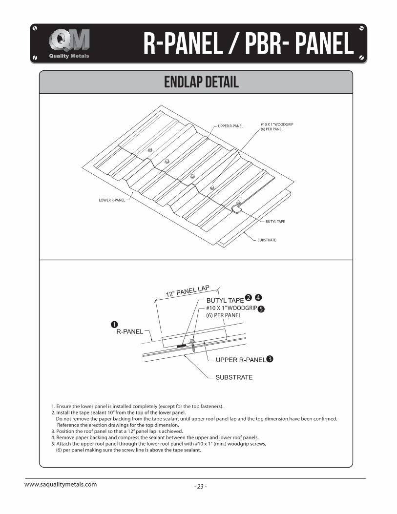
ENDLAP detail
1. Ensure the lower panel is installed completely (except for the top fasteners).2. Install the tape sealant 10” from the top of the lower panel.
Reference the erection drawings for the top dimension.3. Position the roof panel so that a 12” panel lap is achieved.4. Remove paper backing and compress the sealant between the upper and lower roof panels.5. Attach the upper roof panel through the lower roof panel with #10 x 1" (min.) woodgrip screws,
(6) per panel making sure the screw line is above the tape sealant.
UPPER R-PANEL #10 X 1” WOODGRIP(6) PER PANEL
BUTYL TAPE
SUBSTRATE
LOWER R-PANEL
1
2 4
5
3
#10 X 1” WOODGRIP(6) PER PANEL